1
Agilent 8904A
Multifunction Synthesizer
dc to 600 kHz
Technical Specifications
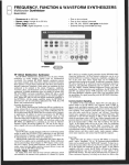
Build complex waveforms
from common signals
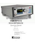
The Agilent Technologies 8904A Multifunction
Synthesizer uses VLSIC technology to create complex signals from six fundamental waveforms. The
standard 8904A digitally synthesizes precise sine,
square, triangle, ramp, white noise, and dc waveforms and routes these signals to a single output.
Option 001 adds three more identical internal synthesizers (channels) which can either modulate the
first synthesizer or be summed to the output. Frequency, amplitude, waveform, phase, and destination can be independently set for each synthesizer.
Available modulation types for channel A include
AM, FM, F M, DSBSC, and pulse modulation. Option
002 adds a second 50 Ω output, providing a second
separate signal for two channel applications.
Option 003 adds fast hop and digital modulation
capability to the 8904A. Option 005 allows multiple
8904As to be phase synchronized for applications
which require the use of more than one 8904A.
Option 006 changes output one of the 8904A from
a 50 Ω floating output to a 600 Ω, high-power balanced output. With this option, the 8904A can
deliver 10 volts rms into a 600 Ω load from 30 Hz
to over 100 kHz. All this unique capability makes
the Agilent 8904A a powerful new tool for demanding applications like VOR, ILS, FM stereo, and communications signaling.
AGILENT 8904A SPECIFICATIONS
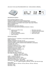
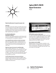
Gaussian Noise
Specifications describe the instruments’ warranted performance (<50 Ω output only unless noted) for automatic operation.
Mathematically derived characteristics denote parameters
which can be derived from specifications and knowledge of the
digital generation methods used in the 8904A. Supplemental
characteristics are intended to provide information useful in
applying the instrument by giving typical, but not warranted,
performance parameters. These are noted as “typical,” “normal,” or “approximate.”
Spectral Characteristic: Equal energy per unit bandwidth
(“white”)
Amplitude Range: 0 to 10 Vp-p into a 50 Ω load1
Resolution: Three and a half digits
Frequency
Range:
Sine wave: 0 Hz to 600 kHz
Square, triangle, ramp: 0 Hz to 50 kHz
Resolution: 0.1 Hz
Accuracy:
Internal 10 MHz timebase: ±50 ppm
External 10 MHz timebase: Same as accuracy and stability
of external timebase
AC amplitude (sinewave)
Range: 0 to 10 Vp-p into a 50 Ω load
Resolution: 31/2 digits
Accuracy (Amplitude >40 mVp-p into 50 Ω):
1%, 0.1 Hz to 100 kHz
3%, 100 kHz to 600 kHz
Flatness (Amplitude >630 mVp-p into 50 Ω):
±0.1% (±0.009 dB), 0.1 Hz to 100 kHz
±1.0% (±0.09 dB), 100 kHz to 600 kHz
Mathematically Derived Characteristics
Noise Flatness (Amplitude >100 mVp-p into 50 Ω):
±0.5 dB, 0.1 Hz to 100 kHz
±1.0 dB, 100 kHz to 600 kHz
Supplemental Characteristics
Number of Outputs: One standard; two with Option 002
Number of Internal Channels: One standard, two with
Option 002; four with Option 001
Standard Waveforms: Sine, square, triangle, ramp, dc, and
Gaussian white noise
AC Amplitude Accuracy: Typically:
Square wave: <3% at 20 kHz
Triangle: <4% at 20 kHz
Gaussian white noise: <5%
Ramp: <7% at 20 kHz
Square Wave Rise-time/Fall-time: Typically <2.5 µs
Spurious (Typically the higher of): –50 dBc or 500 µVp-p,
100 kHz to 600 kHz, 20 MHz BW
Noise Crest Factor: Typically >4.4
Switching Speed (via GPIB): Typically <25 ms
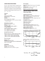
Typical THD+Noise in 80 kHz measurement BW (above 20 kHz,
in a 750 kHz measurement BW) at 5 Vp-p into a 50 Ω load
Spectral Purity (sine wave)
THD+N (Including spurs, amplitude >50 mV rms into 50 Ω):
–63 dBc rms (0.07%), 20 Hz to 7.5 kHz, 30 kHz BW
–63 dBc rms (0.07%), 7.5 kHz to 20 kHz, 80 kHz BW
–55 dBc rms (0.18%), 20 kHz to 100 kHz, 750 kHz BW
Phase (sine wave)
Range: 0 to 359.9°
Resolution: 0.1° or 0.001 radians
Increment Accuracy (Relative to 0° for a fixed frequency):
±0.05°, 0.1 Hz to 100 kHz
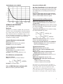
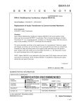
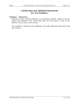
Typical level flatness (1 kHz reference) at 5 Vp-p into a
50 Ω load
DC Amplitude
Range: 0 to ±10 V open circuit
Resolution: Three and a half digits
Accuracy: ±20 mV or ±2.1%, whichever is greater
1.
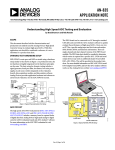
2
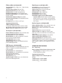
Typical SSB phase noise at 500 kHz
Summation (with Option 001)
Two, Three, or Four Channels may be summed into a single
output. Two or three channels may be summed for modulation of channel A. All combinations of channels are acceptable, EXCEPT FOR: {A+C and B+D} or {A+D and B+C} at
the same time.
Channel-to-Channel Phase Accuracy (Equal amplitude,
sinewave signals summed into one output): +0.1 degrees
or 30 ns, 0.1 Hz to 100 kHz, whichever is greater
Mathematically Derived Characteristics
OPTION 001 SPECIFICATIONS
(50 Ω outputs only)
Modulation
Modulation for channel A ONLY, and specified for
sinewave carrier and modulation. Internal channels
B, C, and D can be used to either collectively modulate channel A with one modulation type, or can
provide simultaneous modulation of channel A with
any of the available modulation types. External
modulation is NOT possible.
Amplitude Modulation (with Option 001)
Rate: 0 Hz to 600 kHz
Depth Range: 0% to 100% of carrier amplitude
Resolution: 0.1% of carrier amplitude
Frequency Modulation (with Option 001)
Rate: 0 Hz to 600 kHz
Deviation Range: 0 Hz up to 600 kHz; however
Fcarrier + Fdeviation ≤600 kHz
Resolution: 0.1 Hz or 31/2 digits, whichever is less
Phase Modulation (with Option 001)
Rate: 0 Hz to 600 kHz
Range: 0° up to 179.9° per channel, however:
AM Accuracy (The higher of): ±0.024% AM or ±0.20% of
setting, up to 20 kHz modulation rate and 100 kHz carrier,
1% to 99% depth
FM Accuracy (The higher of): ±0.1 Hz or ±0.28% of setting,
up to 20 kHz modulation rate, 20 kHz deviation, and where
Fcarrier + Fdeviation ≤100 kHz
F M Accuracy (The higher of): ±0.1° or ±0.28% of setting,
up to 20 kHz modulation rate, where:
DSBSC Peak Envelope Accuracy: Same as amplitude
accuracy, up to 20 kHz modulation rate
Phase Accuracy when One Channel is used to Modulate
Channel A (sinewave): ±0.15° or 30 ns, whichever is
greater, 0.1 Hz to 100 kHz frequency
Supplemental Characteristics
VOR Bearing Accuracy: Typically ±0.05°
AM Accuracy (At a 1 kHz rate and 600 kHz carrier):
Typically <±0.2%
FM Accuracy (At a 1 kHz rate, 20 kHz deviation, and
600 kHz carrier): Typically <±0.2% of setting
Pulse Modulation Level Accuracy: Typically 5% up to 20
kHz pulse rate
DSBSC Carrier Suppression: Typically >72 dB
Intermodulation (Two equal signals summed into one
output): Typically:
<–70 dBc, for frequencies up to 100 kHz
<–60 dBc, for frequencies 100 to 600 kHz
Resolution: 0.1° or 0.001 radians
Pulse or DSBSC Modulation (with Option 001)
Rate: 0 Hz to 50 kHz (up 600 kHz for DSBSC)
Specifications for level accuracy, modulation
accuracy, and spectral purity are all referenced
to the peak of the composite signal less 3 dB.
When signals are summed the specification for
each individual signal is degraded by its amplitude relative to the peak of the composite signal.
3
FM Stereo Mode (with Option 001)
Digital Sequence (with Option 001)
Test Signal Modes: Left = Right, Left = – Right, Left only,
and Right only
Test Tone Frequency Range: 20 Hz to 15 kHz
Composite Signal Level: Up to 10 Vp-p into 50 Ω
Pilot Tone Level: 0% to 100% of composite level
Pilot Tone Level Resolution: 0.1% of composite level
Pilot Tone Frequency Range: 0.1 Hz to 600 kHz (default
frequency 19 kHz)
Pilot Tone Phase Adjustment Range: 0.0 to 359.9°
Subcarrier Frequency Range: 0.1 Hz to 600 kHz (default
frequency 38 kHz)
Pre-emphasis: 25 µsec, 50 µsec, and 75 µsec
User Definable: On level (±10 V open circuit),
Off level (±10 V open circuit), and period
Sequence Entry: Binary, octal, or hexadecimal
Sequence Length: Up to 3,000 bits
Period Duration: 0.10 ms to 655.35 ms
Period Resolution: 0.01 ms (10 µs)
Period Accuracy: ±0.02 ms (±20 µs)
Control Modes (Applies to tone, DTMF and digital
sequence modes): Manual sequence (allows stepping
through sequence), single sequence, and continuously
peat sequence. Sequence can also be triggered by exter
nal TTL pulse.
Supplemental Characteristics
FM Stereo Multiplex Separation:
L-R: Typically >65 dB, audio frequency 20 Hz to 15 kHz
M-S: Typically >70 dB, audio frequency 20 Hz to 15 kHz
Multiplex Subcarrier Suppression: Typically >70 dB
Hop Ram Sequence (with Option 001)
Tone Sequence (with Option 001)
Number of Different Frequencies: 16 user definable tones
each with an individual on time and off time
On-time Duration: 0 ms, 0.80 ms to 655.35 ms
Off-time Duration: 0 ms, 0.80 ms to 655.35 ms (zero off
time and zero on time NOT allowed)
Timing Resolution: 0.01 ms (10 µs)
Timing Accuracy: ±0.02 ms (+20 µs)
Sequence Length: 750 tones, user definable from front
panel or GPIB programmable
DTMF Sequence (with Option 001)
Number of Tone Pairs: 16 standard DTMF tone pairs (0-9,
A-D, #, *). Frequencies per Bell Technical Reference
Publication 48005.
On-time Duration: 0 ms, 1.00 to 655.35 ms
Off-time Duration: 0 ms, 1.00 to 655.35 ms (zero off time
and zero on time NOT allowed)
Timing Resolution: 0.01 ms (10 µs)
Timing Accuracy: ±1 ms
Sequence Length: 750 DTMF tones, user definable from
front panel or GPIB programmable
4
Number of Different States: 16 user definable states each
with an amplitude, frequency, and phase value
Waveforms: Sine, square, ramp, triangle, dc, and white
Gaussian noise
Sequence Entry: Binary, octal, or hexadecimal
Sequence Length: Up to 3,000 tones in binary mode
(two states used), or up to 750 tones in hex mode (all 16
states used)
Sequence Clock Frequency Range: 0.1 Hz to 10 kHz
Sequence Clock Frequency Resolution: 0.1 Hz
Sequence Burst Range: One repetition up to 127
Control Modes: Manual sequence (allows stepping through
sequence), burst sequence (1 to 127), and continuously
repeat sequence. Sequence can be triggered by external
TTL pulse.
OPTION 002 SPECIFICATIONS
(50 Ω outputs only)
Output 1 to Output 2 Phase Accuracy (Sine waves at the
same frequency): ±0.1 degrees or 30 ns, 0.1 Hz to
100 kHz, whichever is greater
Supplemental Characteristics
Output 1 to Output 2 Cross-talk (The higher of):
Typically:
–100 dB or 20 µVp-p, 0.1 Hz to 20 kHz
–95 dB or 20 µVp-p, 0.1 Hz to 100 kHz
–90 dB or 30 µVp-p, 0.1 Hz to 600 kHz
OPTION 003 SPECIFICATIONS
OPTION 006 SPECIFICATIONS
(50 Ω outputs only)
(Sine wave only)
Direct Addressing of Channel A: Up to 16 phasefrequency-amplitude states of channel A may
be preset and directly addressed with four TTLcompatible inputs. Timing for fast hopping must
be provided by an EXTERNAL source.
All specifications for the standard 50 Ω 8904A are
degraded by the accuracy, flatness, and distortion
specifications of the Option 006, 600 Ω transformer
coupled output. Because the transformer output
was designed for passing sinewaves only, all specifications apply to that waveform. The Option 006
output will not pass digital sequences available
with Option 001. In addition, phase accuracy is
degraded and therefore not specified for Option 006.
Digital Modulation: By appropriately setting the 16
direct control registers, the Agilent 8904A may be
used as a digital modulator. Examples of signals
which can be generated with this technique
include FSK or multilevel FM (up to 16 levels),
BPSK, QPSK, and QAM.
Supplemental Characteristics
Switching Speed:
Via Digital Port: Typically <8 µs, <20 µs for full
filter settling
Via GPIB: Typically <8 ms
Maximum Switching Rate (via digital control port):
Approximately 400 kHz
Maximum Allowable Address Skew (via digital port):
25 ns for valid results
OPTION 005 SPECIFICATIONS
(50 Ω outputs only)
Unit to Unit Phase Accuracy: Additional 30 nsec error, 0.1
Hz to 100 kHz. (Total phase error between units is then the
greater of ±0.1° or 60 nsec, 0.1 Hz to 100 kHz.)
Maximum Number of Synchronized Units: 8 units using
low-loss power splitters (for a total of 16 phase related outputs if all units have Option 002)
Recommended Power Splitters:
≤4 units synchronized: Mini-circuits model ZSC-4-3
or equivalent
≤8 units synchronized: Mini-circuits model ZFSC-8-1
or equivalent
Supplemental Characteristics
Unit to Unit Phase Accuracy: Typically <15 nsec additional
error, 0.1 Hz to 100 kHz (Total typical phase error between
units is then the greater of ±0.1 degree or 30 nsec, 0.1 Hz
to 100 kHz)
Output Type: Fully floating/balanced transformer coupled
output
Usable Output Frequency Range: 30 Hz to 200 kHz
AC Amplitude (sine wave only)
Range:
Open circuit: 0 to 20 Vrms
600 Ω load: 0 to 10 Vrms
150 Ω load: 0 to 4 Vrms
50 Ω load: 0 to 1.5 Vrms
Resolution: 31/2 digits
Accuracy (amplitude >40 mVrms into a balanced
600 Ω load):
6% (0.5 dB) 30 Hz to 20 kHz
12% (1.0 dB) 30 Hz to 100 kHz
Flatness (amplitude >40 mV rms into a balanced
600 Ω load, 1 kHz reference):
+0.15 dB, –0.15 dB, 30 Hz to 20 kHz
+0.15 dB, –0.75 dB, 30 Hz to 100 kHz
Spectral Purity (sine wave only)
THD+N (including spurs, amplitude 140 mVrms to
10 Vrms into a balanced 600 Ω load):
–46 dB (0.50%), 30 Hz to 300 Hz, 30 kHz BW, amplitude
<1 Vrms into a balanced 600 Ω load
–60 dB (0.10%), 300 Hz to 7.5 kHz, 30 kHz BW
–63 dB (0.07%), 7.5 kHz to 20 kHz, 80 kHz BW
–55 dB (0.18%), 20 kHz to 100 kHz, 750 kHz BW
Supplemental Characteristics
Balance: Typically >40 dB, 30 Hz to 50 kHz
Output Impedance: Nominally 600 Ω at 1 kHz
Flatness (amplitude >40 mV rms into a balanced 600 Ω
load, 1 kHz reference): +0.15 dB, –4.0 dB, 30 Hz to 200 kHz
THD+N (including spurs, amplitude 140 mVrms to 1 Vrms
into a balanced 600 Ω load): <–50 dB (0.32%), 30 Hz to
300 Hz, 30 kHz BW
5
GENERAL
AGILENT 8904A ORDERING INFORMATION
Store Recall: 35 nonvolatile
Output Type: Floating or grounded, GPIB programmable.
Maximum float voltage (signal + float): 10 V peak maximum
from high or low side to chassis ground.
Zero-crossing Outputs (Available in channel configuration
mode only): For each channel, a TTL-compatible zero-crossing
output and polarity output are provided. The zero-crossing
output pulses high for approximately 600 ns each time the
channel phase goes through 0 or 180°. The polarity output is
high for phases of 0 to 180°s, low for 180 to 360°. These
outputs do not reflect any user-specified phase offsets.
External Timebase Input: 10 MHz accepted at a nominal
level of 0.1 to 5 V peak, automatic switching.
Timebase Output: Output level >0 dBm (0.3 V peak) into
a 50 Ω load. Output signal will be the internal timebase
unless an external timebase is connected to the external
timebase input. When an external timebase is connected,
it will be routed to the timebase output connector.
Temperature:
Operating: 0° C to 50° C
Storage: –20° C to 70° C
Humidity Range: 95% RH, 0° C to 40° C
Remote Operation: GPIB. A11 functions except the line
switch are remotely controllable
GPIB Compatibility: SH1, AH1, T6, TEO, L4, LEO, SR1, RL1,
PP1, DC1, DTO, CO
Power: 100/120 V (±10%); 48 to 440 Hz
220/240 V (±10%); 48 to 66 Hz. 80 VA maximum
Weight: Net 5.9 kg (12.8 lb.); Shipping 13 kg ( 28.6 lb.)
Dimensions: 133 mm H x 213 mm W x 513 mm D
(5.25 x 8.36 x 20.2 inches)
System II Size: 51/4 H x 51/2 W x 20 D
EMI: Meets conducted and radiated interference of VDE
0871/6.78 class B (radiated at 10 meters). Meets MIL 461B
conducted (CE03) and radiated (RE02) interference.
8904A Multifunction Synthesizer
(One 50 Ω output standard)
Supplemental Characteristics
Output Impedance: Typically 50 Ω ±3%, 0.1 Hz to 600 kHz
6
Option 001: Add three internal channels, channel A modulation, channel summation, and channel A sequence capability.
Option 002: Add second internal synthesizer and 50 Ω output
Option 003: Add fast hop and digital modulation capability
Option 004: Move outputs to rear panel (Not available with
either Option 005 or 006)
Option 005: Add unit to unit phase synchronization capability
Option 006: Changes output 1 from a 50 Ω output to a
transformer coupled, 600 Ω balanced output
Option 910: Provides a total of two sets of operation and
calibration manuals (08904-90007) and service manuals
(08904-90008)
Option 915: Add service manual (Does not come standard,
part number 08904-90008)
Option W30: Extended repair service
08904-61024: Rack mount kit for a single 8904A (includes
are required parts and hardware)
08904-61025: Rack mount kit for mounting two 8904As side
by side (includes all required parts and hardware)
9211-2682: Ruggedized transit case for one 8904A
Retrofit Kit Ordering Information
8904A Retrofit kits (all are customer retrofittable)
11816A: Retrofit kit for Option 001
11817A: Retrofit kit for Option 002
11818A: Retrofit kit for Option 003
11827A: Retrofit kit for Option 005 (not available for units
with serial numbers less than 2948AXXXXX)
11837A: Retrofit kit for Option 006 (not available for units
with serial numbers prior to 2948AXXXXX)
Agilent Technologies’ Test and Measurement
Support, Services, and Assistance
Agilent Technologies aims to maximize the value you receive,
while minimizing your risk and problems. We strive to ensure
that you get the test and measurement capabilities you paid
for and obtain the support you need. Our extensive support
resources and services can help you choose the right Agilent
products for your applications and apply them successfully.
Every instrument and system we sell has a global warranty.
Support is available for at least five years beyond the production life of the product. Two concepts underlie Agilent’s
overall support policy: “Our Promise” and “Your Advantage.”
By internet, phone, or fax, get assistance with all your
test and measurement needs.
Our Promise
“Our Promise” means your Agilent test and measurement equipment will meet its advertised performance and functionality.
When you are choosing new equipment, we will help you with
product information, including realistic performance specifications and practical recommendations from experienced test
engineers. When you use Agilent equipment, we can verify that
it works properly, help with product operation, and provide
basic measurement assistance for the use of specified capabilities, at no extra cost upon request. Many self-help tools are
available.
Europe:
(tel) (31 20) 547 2323
(fax) (31 20) 547 2390
Your Advantage
“Your Advantage” means that Agilent offers a wide range of
additional expert test and measurement services, which you
can purchase according to your unique technical and business
needs. Solve problems efficiently and gain a competitive edge
by contracting with us for calibration, extra-cost upgrades, outof-warranty repairs, and on-site education and training, as well
as design, system integration, project management, and other
professional services. Experienced Agilent engineers and technicians worldwide can help you maximize your productivity,
optimize the return on investment of your Agilent instruments
and systems, and obtain dependable measurement accuracy
for the life of those products.
For more information visit our website:
www.agilent.com/find/wireless
Online Assistance
www.agilent.com/find/assist
Phone or Fax
United States:
(tel) 1 800 452 4844
Canada:
(tel) 1 877 894 4414
(fax) (905) 206 4120
Japan:
(tel) (81) 426 56 7832
(fax) (81) 426 56 7840
Latin America:
(tel) (305) 269 7500
(fax) (305) 269 7599
Australia:
(tel) 1 800 629 485
(fax) (61 3) 9210 5947
New Zealand:
(tel) 0 800 738 378
(fax) (64 4) 495 8950
Asia Pacific:
(tel) (852) 3197 7777
(fax) (852) 2506 9284
Product specifications and descriptions in this
document subject to change without notice.
Copyright © 1989, 2000 Agilent Technologies
Printed in U.S.A. 9/00
5965-9456E