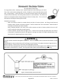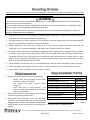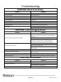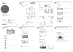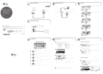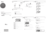
1
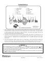
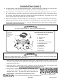
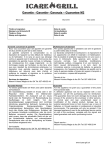
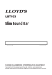
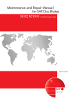
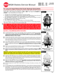
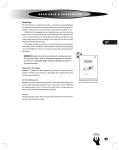
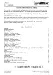
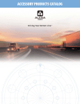
INSTALLATION, INSTRUCTION AND SERVICE MANUAL Brake/Trailer Dealer – Please provide to consumer. Consumer – Read and follow instructions. Keep with trailer for reference. A Titan Company 2345 East Market Street Des Moines, IA 50317 PHONE: 800-USA-BEAR or 800-872-2327 FAX: 515-265-9212 Page 1 of 9 #48780 02-2015 Rev. 1 1. Introduction .................................................................................................................................... 3 2. General Information ....................................................................................................................... 3 3. Safety Information ......................................................................................................................... 3 4. Installation ................................................................................................................................... 4-5 5. Solenoid Backup Valve ................................................................................................................... 6 6. Bleeding Brakes .............................................................................................................................. 7 7. Maintenance ................................................................................................................................... 7 8. Replacement Parts ......................................................................................................................... 7 9. Troubleshooting ............................................................................................................................. 8 10. Warranty ......................................................................................................................................... 9 A Titan Company 2345 East Market Street Des Moines, IA 50317 PHONE: 800-USA-BEAR or 800-872-2327 FAX: 515-265-9212 Page 2 of 9 #48780 02-2015 Rev. 1 Thank you for purchasing a TITAN Premier Disc Brake system. Disc brakes provide positive benefits over drum brakes including longevity, better performance, and less maintenance than comparable drum brakes. Disc Brakes provide more sustained braking performance over repeated use due to improved cooling capabilities vs. drum brakes. TITAN Premier Disc Brake systems are for trailers rated up to 24,000 pound Gross Vehicle Weight Rating (GVWR). TITAN Premier Disc Brakes are designed to work with surge actuators or electric over hydraulic brake actuators, both of which TITAN produces. See our Actuators catalog for information on these products. TITAN Premier Disc Brakes are designed as an integral hub and rotor cast as a single component. Following casting and machining processes, wheel studs are pressed into finished rotors. TITAN Premier Disc Brake coating is Dacromet, which provides excellent corrosion resistance over zinc plating, giving several years of added protection for your brake components with proper maintenance. 1) Brake installation, maintenance, or repair should ONLY be performed by qualified persons who have training or knowledge of brakes and brake systems 2) When installing, maintaining, or repairing TITAN equipment, wear eye protection as well as other necessary personal protective equipment. 3) TITAN equipment must be maintained in safe working order at all times. Trailer equipment should be inspected before, during, and after use for wear and damage. 4) Perform frequent and regular inspection of trailer and equipment. a. Rotors – Evidence of scoring, cracks, warping, excessive wear, or excessive heat. b. Pads – Evidence of uneven or excessive wear. c. Brake Actuator – Proper brake fluid levels. No contaminants in fluid. d. Caliper and Brake Lines – Hose connections are tight, fix brake fluid leaks. e. Fasteners – Bolts and fasteners are tight. 5) Confirm brake actuator being used can supply enough hydraulic pressure and volume to actuate disc brakes. As a common rule, disc brakes require more pressure and larger volume of fluid than drum brakes of same size. 6) Use DOT3 or DOT4 brake fluid. Failure to use correct brake fluid may result in brake failure. 7) Be familiar with state laws in operation of towed vehicles, especially with regard to brake and braking requirements. Towing a trailer may require additional braking time and distance. Allow for this in driving habits while towing. 8) Make certain equipped trailer is safely supported at all times during installation, maintenance or repair. 9) After every hookup, test and confirm trailer brake system is operating correctly and adequately before transportation on roads. A Titan Company 2345 East Market Street Des Moines, IA 50317 PHONE: 800-USA-BEAR or 800-872-2327 FAX: 515-265-9212 Page 3 of 9 #48780 02-2015 Rev. 1 Items show in Figure 1: 2 1. 2. 3. 4. 5. 6. Caliper Bracket Bleeder Ports Caliper Brake Pads Seal Inner Bearing 1 3 5 7 6 7. 8. 9. 10. 11. 12. Rotor Outer Bearing Washer Slotted Nut Cotter Pin Bearing Protector 8 9 4 Figure 1 Exploded View (12" Rotor Shown) 10 11 12 The numbers in this diagram are referenced by <#> throughout this manual. 1. Before installing disc brakes, verify components being installed match and have correct specifications. Check bearing diameters of spindle to match hub and brake flange dimensions to caliper bracket. For surge actuators or electric hydraulic brakes, verify ability to support disc brakes. Disc brakes require higher pressures and volumes of fluid versus drum brakes to operate properly. 2. If applicable, remove old equipment off axle spindle and brake flange. Retain washer <9>, slotted nut <10>, and cotter pin <11> (or other retaining device). These components will be reused during installation and do not come with disc brake kits. Although there are standard spindle sizes, it is possible these parts have unique specifications. 3. Clean face of brake flange. Mount caliper bracket <1> to brake flange. Caliper bracket mounts to spindle side (outside) of brake flange. When installing caliper bracket, recommended orientation should be 10 o’clock or 2 o’clock position. All calipers should be on same side of axle, such as, all installed on front side, or rear side. NOTICE When installing brakes on tandem or triple axle trailers, it is recommended that brakes are installed on ALL axles. This is so trailer GVWR does not exceed total braking capacity. For example, a 14,000 GVWR tandem axle trailer, with one set of brakes, has braking capacity of 7,000 lbs, one-half GVWR. It is advised to check with local state laws including states traveled through on brake regulations. Note: IF brakes must not be installed on all axles, recommendation is that brakes are installed on rear most axle(s) to reduce risk of skidding during braking. A Titan Company 2345 East Market Street Des Moines, IA 50317 PHONE: 800-USA-BEAR or 800-872-2327 FAX: 515-265-9212 Page 4 of 9 #48780 02-2015 Rev. 1 4. Pre-pack bearings <6, 8> with high temperature grease. Install inner bearing <6> and seal <5> in hub rotor unit <7>. Slide hub rotor onto spindle. Install outer bearing <8>, washer <9>, and slotted nut <10>. 5. Once Step 4 items are installed back onto spindle, rotate rotor slowly while tightening slotted nut <10> to 50 ftlbs. Loosen slotted nut removing all torque. Do not rotate hub while slotted nut is loose. Finger tighten slotted nut until snug. Back slotted nut off until first slot lines up with hole in spindle shaft. Install cotter pin <11> and secure. Nut will rotate a small amount with cotter pin installed. 6. When mounting caliper, orient with bleeder port <2> pointing up. If caliper has two bleeder ports, bleed from highest bleed screw during Step 8. Install caliper <3> with brake pads <4> onto caliper bracket <1> by sliding opening between brake pads over rotor <7>. Use two caliper guide bolts to attach caliper to caliper bracket. Torque caliper guide bolts to 40-50 ft-lbs. WARNING Do not over tighten spindle nut. Doing so may cause bearing failure. Numbers in this diagram are referenced by <#> throughout this manual. Figure 2 Exploded View (10" & 12" Caliper Shown) 2 Items shown in Figure 2: 4 7 3 18 1 3 14 15 1 17 2. 3. 4. 13. 14. 15. 16. 17. 18. Bleeder Ports Caliper Brake Pads Guide Bolt Sleeve Bushing Guide Bolt Sleeve Guide Bolt Adapter Port Dust Boot Piston Seal WARNING TITAN uses a floating caliper design. Do not paint guide bolts or guide bolt sleeves. Doing so will inhibit caliper movement and reduce functionality of brake system. 7. Check clearances around all brake components including rotor, caliper bracket, and caliper. Make sure rotor spins freely. (Drag should decrease significantly after roughly 100 miles of use.) Caliper should slide slightly on guide bolts with some effort. 8. Attach brake lines to caliper making sure all connections are tight and without leaks. Once complete, begin process of bleeding brakes. See section on Bleeding Brakes for detailed instructions. 9. Once bleeding is completed, install wheel per manufacturer’s specs. As a general rule, follow Figure 3 for tightening order of wheel nuts. Tightening wheel nuts in this order helps ensure concentricity of wheel assemblies. Torque wheel nuts to manufacturer’s specs. Figure 3 Wheel Nut Tightening Pattern A Titan Company 2345 East Market Street Des Moines, IA 50317 PHONE: 800-USA-BEAR or 800-872-2327 FAX: 515-265-9212 Page 5 of 9 #48780 02-2015 Rev. 1 (For Surge Brake Trailers Only) For surge brake trailers, a backup valve is typically required to allow backing up of trailers. This is due to disc brakes working well in either a forward or reverse direction when paired with a surge actuator. Unlike disc brakes, uni-servo drum brakes require very little pressure to work in forward direction, and much greater pressure in reverse direction. This allows tow vehicles to overpower brakes during backing up without a backup valve. This can also be alleviated by installing free-backing drum brakes. Checklist for disc brakes: Make sure backup solenoid is screwed directly into back of master cylinder. No fittings should be used between master cylinder and backup solenoid. Confirm solenoid has correct orientation. Male threads of solenoid screw directly into master cylinder. Note: If backup solenoid is not used, ensure orifice connector on back of master cylinder hole size is 1/8” (.125”) to allow for disc brakes to work properly. Confirm solenoid is wired to back-up light circuit. A distinct click sound will be heard when tow vehicle’s transmission is switched into reverse. See Figure 4 for wiring instructions for TITAN’s solenoid backup valve. Note location for tightening valve to master cylinder. WARNING - Confirm actuator installed is designed for disc brakes. Failure to do so may result in premature brake wear or brake failure. - NEVER tighten or loosen solenoid by small hex fitting on top of solenoid. Only tighten by bottom larger portion as shown in Figure 4. Failure to do so can cause internal damage to solenoid. - Never tow trailers equipped with surge actuator and backup solenoid if backup light circuit is ON other than when tow vehicle’s transmission is in reverse. This may cause brake system to be disabled during transporting. Figure 4 Solenoid Backup Valve Instructions A Titan Company 2345 East Market Street Des Moines, IA 50317 PHONE: 800-USA-BEAR or 800-872-2327 FAX: 515-265-9212 Page 6 of 9 #48780 02-2015 Rev. 1 Instructions are to be used with actuator manufacturer’s instructions for filling and bleeding brakes. instructions pertain to surge and electric over hydraulic actuator units. These WARNING -Use fresh DOT3 or DOT4 brake fluid from sealed container. DO NOT reuse brake fluid. Failure to use fresh brake fluid increases chance of brake failure. -Use care when handling brake fluid. DO NOT allow brake fluid to contact painted surfaces. It will damage surface finishes. Wipe up spills immediately and wash area with water. -This is a high pressure system. ALL air must be removed. Any air in brake lines will cause brakes not to function properly. Bleed brake system completely. 1. Confirm all brake lines run flat as possible. Air bubbles gather in high spots. Doing this helps reduce chances of air pockets forming at locations away from bleeder ports. 2. For surge actuators, set trailer so actuator is low as possible, and brake calipers high as possible during bleeding process. This helps direct air bubbles to calipers to be bleed. 3. Install bleeder hose (A small section of hose run into clear container partially filled with brake fluid and submerged. This is to observe bubbling) on top bleeder port of caliper farthest from actuator. 4. Pressurize system using actuator manufacturer’s suggested method. Making sure an adequate amount of fluid is in reservoir. Never allow master cylinder to run dry as entire bleeding process will need to be restarted if air is introduced into brake lines. Once brake lines are pressurized, open top bleeder port on caliper one turn. Brake fluid will vent to atmosphere through this opening. Before depressurizing system, close bleeder port securely to prevent air being reintroduced into brakes lines. 5. Caliper bleeding is finished once no air is released. Repeat Step 3 & 4 for each caliper working closer to actuator. 6. Following bleeding, verify bleeder valves are closed. Fill master cylinder with DOT3 or DOT4 fluid. Install cap. 7. Check proper function of actuator and brakes before transport. 1. Perform these checks before each and every towing: Visually check brake components (See Safety Information: Page 4, Section #4). Test actuator and brake function before transport. Check fluid levels in brake reservoir. Use actuator manufacturer’s guidelines for filling and maintaining fluid levels. 2. Wash brake components after exposure to salt or other corrosives to prevent premature wear. 3. Occasionally during transport, check hub and brake assemblies for excessive heat that can be caused by dragging brakes. DO NOT TOUCH BRAKE COMPONENTS. Brake components can be extremely hot, especially after braking. PARTIAL BRAKE COMPONENT LIST ITEM DESCRIPTION TITAN PART # 10" Integral Hub/Rotor, Premier, 3.5K TROTORHB10DAC 12" Integral Hub/Rotor, Premier, 5K & 6K TROTORHB12DAC 13" Integral Hub/Rotor, 1/2" Lug, Premier, 7K TRTRHB13378DAC 13" Integral Hub/Rotor, 9/16" Lug, Premier, 8K TRTRHB13389DAC Caliper, Premier 225 (10" and 12" Rotors) TDBC225DAC Caliper, Premier 250 (13" Rotor) TDBC250DAC Caliper Pads 225, Premier TDBC2250PAD Caliper Pads 250, Premier TDBC2500PAD For complete list of parts, view this information online at www.titan-intl.com/trailer-components or contact Customer Service at 1-800-872-2327. A Titan Company 2345 East Market Street Des Moines, IA 50317 PHONE: 800-USA-BEAR or 800-872-2327 FAX: 515-265-9212 Page 7 of 9 #48780 02-2015 Rev. 1 SYMPTOM: Weak Or No Brakes CAUSES REMEDY Broken/Kinked Brake Line Replace/Repair As Required Air In Brake System Bleed Brake System Excessively Worn Or Damaged Brake Pads Replace Brake Pads Excessively Worn Or Damaged Rotor Replace Rotor Overloaded Capacity Lighten Load Malfunctioning Actuator Troubleshoot System Foreign Material In Brake Line Flush and Clean Thoroughly. Re-Bleed System Low Hydraulic Fluid Fill With New DOT3 or DOT4 Brake Fluid Check Tightness Of Brass Adapters Leaky Caliper Rebuild/Replace Caliper SYMPTOM: Locking/Dragging Brakes CAUSES REMEDY Check Tow Vehicle Back-Up Light Circuit. Check 12V Solenoid. (Should Hear A "Click" When 12V DC Is Applied To Lead Wire) (In Reverse) 12V Solenoid Valve Is Inoperative Check Connection To Tow Vehicle Back-Up Light Circuit. Check Trailer Ground Connection (Do Not Depend On Hitch Connection To Provide Ground.) Trailer Should Have Dedicated Ground Wire Connected To Grounding Lug Check For Foreign Material In Brake Lines. Flush Fluid Caliper Piston Not Retracting Check For Internal Corrosion Check For Proper Movement On Guide Bolts. Adjust To Proper Torque Improper Fluid Flush And Replace With DOT3 or DOT4 Brake Fluid Inspect And Release Breakaway Cable Per Manufacturer’s Recommendations Breakaway Cable Partially Engaged Bent Guide Bolt/Caliper Mounting Bracket Replace Damaged Components Worn Wheel Bearings Check Wheel Bearings And Raceways, Replace As Required SYMPTOM: Noisy Brakes CAUSES Caliper Mounting Bracket Bolts Loose Caliper Guide Bolts Loose Spindle Nut Loose REMEDY Tighten/Replace As Necessary Replace Caliper Bracket If Threads Are Damaged Apply Thread Locker. Tighten Bolts Check Threads. Tighten To Specifications A Titan Company 2345 East Market Street Des Moines, IA 50317 PHONE: 800-USA-BEAR or 800-872-2327 FAX: 515-265-9212 Page 8 of 9 #48780 02-2015 Rev. 1 LIMITED WARRANTY Limited Warranty Titan Tire Corporation (TITAN) warrants its products to be free from defects in material and workmanship for three years from date of delivery to the original purchaser when properly installed, used, and maintained by the purchaser. This warranty does not apply to damage or loss caused by any or all of the following circumstances or conditions: Freight damage. Parts, accessories, materials or components not obtained former approved in writing by TITAN. Misapplication, misuse and failure to follow the directions or observe cautions and warnings on installation, operation, application, inspection or maintenance specified in any TITAN quotations, acknowledgements, sales literature, specification sheet or installation instructions and service manual (“applicable literature”) If any TITAN products are found upon TITAN’s examination to have been defective when supplied, TITAN will either: credit the purchaser’s account for the purchase price of the TITAN product; or repair the product. TITAN has sole discretion in choosing which option to provide. For this LIMITED WARRANTY to apply, TITAN must receive notice of the alleged defect within 30 days of either the discovery of the alleged defect or the expiration of the warranty period, whichever is earlier. Any claim not made within this period shall conclusively be deemed waived. If requested by TITAN, purchaser shall return the alleged defective product to TITAN for examination at TITANS’s direction and expense. TITAN will not pay for expenses incurred in returning a product to TITAN without TITAN’s prior written authority. TITAN shall not be liable for any other expenses purchaser incurs to remedy any defect. Purchasers waive subrogation on all claims under any insurance. Limitation of Liability It is expressly agreed that the liability of TITAN is limited and TITAN does not function as an insurer. THE REMEDIES SET FORTH IN THIS WARRANTY SHALL CONSTITUE THE EXCLUSIVE REMEDIES AVAILABLE TO THE PRUCHASER OR USER AND ARE IN LIEU OF ALL OTHER REMEDIES, EXPRESS OR IMPLIED. THE LIABILITY OF TITAN, WHEATHER IN CONTRACT, IN TORT, UNDER ANY WARRANTY OR OTHERWISE, SHALL NOT EXCEED THE PURCHASE PRICE OF THE PARTICULAR PRODUCT MANUFACTURED, SOLD OR SUPPLIED BY TITAN. To Obtain Technical Assistance To enable TITAN to respond to a request for assistance or evaluation of customer or user operation difficulty, please provide at a minimum the following information by calling 1-800-872-2327 or within Iowa 1-515-265-9200: Model number, serial number and all other data on the specific component which appears to be involved in the difficulty. The date and from whom you purchased your TITAN product. State your difficulty, being sure to mention at least the following: Application, Nature of load involved, and Weight of the load. TITAN EXTENDS NO WARRANTY, EXPRESS OR IMPLIED, ON PRODUCTS NOT MANUFACTURED BY TITAN OR TO TITAN’S DESIGN SPECIFICATION, INCLUDING BUT NOT LIMITED TO SUCH ITEMS AS NON-TITAN TIRES, BRAKES, ACTUATORS, BEARINGS, HOSE AND TUBING, PURCHASER’S RECOURSE SHALL BE LIMITED TO ANY WARRANTY OF THE PERSPECTIVE MANUFACTURERS. THIS WARRANTY EXCLUDES ALL IMPLIED WARRANTIES OF MERCHANTABILITY OR FITNESS FOR A PARTICULAR PURPOSE OR ANY PURPOSE. THIS WARRANTY DOES NOT COVER NOR EXTEND TO INCIDENTAL OR CONSEQUENTIAL DAMAGE. Some states do not allow the exclusion or limitation of incidental or consequential damages, so the above limitation or exclusion may not apply to you. No representative has authority to make any representation, promise or agreement except as stated in this Limited Warranty. TITAN reserves the right to make design and other changes upon its products without any obligation to install the same on any previously sold or delivered products. THERE ARE NO WARRANTIES WHICH EXTEND BEYOND THOSE DESCRIBED ABOVE. EFFECTIVE JANUARY 1, 1998 THIS WARRANTY SUPERSEDEDS ALL PRIOR WARRANTIES, WIRTTEN OR IMPLIED. A Titan Company 2345 East Market Street Des Moines, IA 50317 PHONE: 800-USA-BEAR or 800-872-2327 FAX: 515-265-9212 Page 9 of 9 #48780 02-2015 Rev. 1