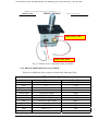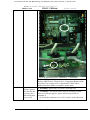
1
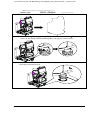
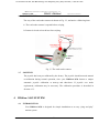
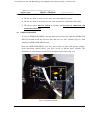
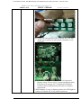
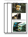
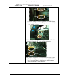
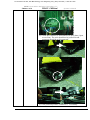
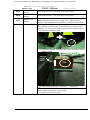
To Purchase This Item, Visit BMI Gaming | www.bmigaming.com | (800) 746-2255 | +1.561.391.7200 IMON Internet Motion Navigator Corporations, Inc. IMOtion!-iGO IMON / IMOtion! TABLE OF CONTENTS Operator’s Manual 1 INTRODUCTION………………………………………………………………………………………..3 2 SPECIFICATIONS………………………………………………………………………………………4 2.1 IMOtion!-iGO MOTION BASE................................................................................................ 4 3 INSTALLATION………………………………………………………………………………………..6 3.1 SERVICE KIT ........................................................................................................................... 6 3.2 SET UP INSTRUCTIONS ....................................................................................................... 6 3.2.1 3.2.2 3.2.3 3.2.4 3.3 3.4 3.5 3.6 3.7 4 PRE-INSTALL PREREQUISITES / CAUTIONS.......................................................................6 UNPACKING AND INSTALLING PROCEDURE OF IMOtion!-iGO .....................................7 DISMANTLING PROCEDURE..................................................................................................11 REPACKING PROCEDURE ......................................................................................................11 STANDARD HANDLING PROCEDURES.......................................................................... 12 DOLLAR BILL ACCEPTOR INSTALLATION INSTRUCTIONS(only for American)13 COIN ACCEPTOR.................................................................................................................. 14 CARD READER ...................................................................................................................... 15 JOYSTICK ............................................................................................................................... 15 IMOtion!-iGO SYSTEM………………………………………………………………………………...15 4.1 INTRODUCTION ................................................................................................................... 15 4.2 OPERATOR POWER PANEL .............................................................................................. 16 4.3 OPERATOR MENU................................................................................................................ 16 4.3.1 4.3.2 4.3.3 4.3.4 4.3.5 4.3.6 4.3.7 4.3.8 4.3.9 4.3.10 4.3.11 4.3.12 COIN OPTIONS............................................................................................................................17 GAME OPTIONS..........................................................................................................................22 JOYSTICK SETTING ..................................................................................................................24 LANGUAGE SETTING ...............................................................................................................26 SYSTEM TIME SETTING ..........................................................................................................27 VOLUME SETTING ....................................................................................................................28 DEVICE TEST ..............................................................................................................................28 SOFTWARE UPGRADE..............................................................................................................29 SHUTDOWN SYSTEM ................................................................................................................32 STATISTIC....................................................................................................................................33 RESET ............................................................................................................................................34 EXIT ...............................................................................................................................................35 4.4 PLAYER GAME SELECT MENU........................................................................................ 36 5 MAINTENANCE AND DIAGNOSTIC………………………………………………………………..37 5.1 INSPECTION SCHEDULE ................................................................................................... 37 5.2 MOTION BASE MAINTENANCE ....................................................................................... 37 5.2.1 CALIBRATION TEST PROCESURE........................................................................................37 6 TROUBLESHOOTING…………………………………………………………………………………38 6.1 LAYOUT OF THE CONTROL PANEL BOX UNIT.......................................................... 38 6.1.1 FIGURE REPRESENTATION....................................................................................................38 6.1.2 DEVICES DEFINITTIONS OF CONTROL PANEL BOX......................................................41 6.2 ELECTRIC DEVICES ON THE BASE PLATE.................................................................. 43 6.2.1 FIGURE REPRESENTATION....................................................................................................43 6.2.2 DEVICES DEFINITIONS ON BASE PLATE ...........................................................................45 1 Rev. 1.00 To Purchase This Item, Visit BMI Gaming | www.bmigaming.com | (800) 746-2255 | +1.561.391.7200 IMON Internet Motion Navigator Corporations, Inc. IMOtion!-iGO IMON / IMOtion! Operator’s Manual 6.3 COCKPIT ELECTRIC UNIT EXPOSITION...................................................................... 46 6.3.1 FIGURE REPRESENTATION....................................................................................................46 6.3.2 DEVICES DEFINITIONS ON COCKPIT .................................................................................47 6.4 REFERENCE........................................................................................................................... 48 6.4.1 REFERENCE (1): Over Travel recovery procedure ....................................................................48 6.4.2 REREFENCE (2): IMOtion!-iGO startup and shutdown procedure ..........................................50 6.5 SYSTEM ERROR CODE DEFINITION.............................................................................. 50 6.6 TROUBLESHOOTING LIST ................................................................................................ 50 6.7 COMPONENT REPLACEMENT PROCEDURE LIST ..................................................... 50 2 Rev. 1.00 To Purchase This Item, Visit BMI Gaming | www.bmigaming.com | (800) 746-2255 | +1.561.391.7200 IMON Internet Motion Navigator Corporations, Inc. IMOtion!-iGO 1 INTRODUCTION IMON / IMOtion! Operator’s Manual Thank you for purchasing the IMOtion!-iGO “@Motion System” developed by IMON in cooperation with IMOtion! for distribution in North America, South America and the United Kingdom. This manual will guide you through the setup, operation, and maintenance of IMOtion!-iGO the ultimate multi-game motion system for arcade environments. This unit is different from any other arcade machine you have ever owned. IMOtion!-iGO is a fully interactive coin-operated motion simulator that creates a virtual reality environment and provides a truly unique game experience for players. Capable of any motion through 2.5 degrees of freedom (also known as D.O.F.) movement (pitch, roll, and hybrid heave), this system enables realistic simulation needed for any software program. IMOtion!-iGO is powered by electric motors, rather than higher maintenance pneumatic or hydraulic actuators that have been used to power most motion simulators in the past. The motion system is powered by IMON’s patented design; a powerful, mini-motion base platform with physics-based motion dynamics, known as the Hex-Glider. Players will experience realism like never before as they “feel” all the exciting action they see occurring on screen, in total synchronization with game play. One of IMOtion!-iGO’s most unique features is that the platform has the capability to run multiple games or motion rides on the same unit. Future titles will be easily and quickly added, giving the player many games to choose from by using our player-selectable menu. Together, these factors combine to offer you the most advanced, economical and exciting motion arcade system available! Sent Questions and Comments to: Sent Questions and Comments to: Customer Support in other area IMON, No.6-1, Datung Rd., Tucheng City, Taipei County 236, Taiwan (R.O.C) Tel. +886-2-22676317 Fax +886-2-2267-5901 www.imon.com.tw [email protected] Customer Support in North America & U.K. IMOtion !., 8 Sunset Way, Suite 103 Henderson, NV 89014 Tel. 702-614-9800 Fax 702-614-9300 www.IMOtionusa.com [email protected] 3 Rev. 1.00 To Purchase This Item, Visit BMI Gaming | www.bmigaming.com | (800) 746-2255 | +1.561.391.7200 IMON Internet Motion Navigator Corporations, Inc. IMON / IMOtion! IMOtion!-iGO Operator’s Manual 2 SPECIFICATIONS SPECIFICATIONS OF IMOtion!-iGO @MOTION SYSTEM Each IMOtion!-iGO is composed of one complete unit, known as the Motion Base. The dimensions given are for IMOtion!-iGO installed footprint. z IMOtion!-iGO @Motion System Unit o Minimum Installed Footprint 2.1 US: 65” x 49” Metric: 1.66m x 1.26m IMOtion!-iGO MOTION BASE IMOtion!-iGO Motion Base Simulator IMOtion!-iGO Motion Simulator z 65” x 49”x 82” / 1,278 lbs z 166 x 126 x 209cm / 498 kg z 65” x 50” x 80” / 1100 lbs z 165 x 127 x 203 cm / 580 kg z 2.5 degree of freedom (D.O.F.) mini motion Installed Dimensions / Weight (LxWxH) Shipping Dimensions (LxWxH) Motion system base: AC-powered, motor-driven actuators z 2 button function flight joystick z 2 speed direction gear shifter z Motion stop switch Player Weight Limit z 220 lbs. Center of Gravity z Directly over Two Axis Motor Pedestal Dimension z Equilateral triangle, approx. 12” front Control inputs/feedback 4 Rev. 1.00 To Purchase This Item, Visit BMI Gaming | www.bmigaming.com | (800) 746-2255 | +1.561.391.7200 IMON Internet Motion Navigator Corporations, Inc. IMOtion!-iGO IMON / IMOtion! Motors Power Requirements – Plugs located on rear of display cabinet as input 2. Pad Chair Operator’s Manual z (3) 2 @ .54 Hp/ 1 @ .09 AC motors z See 2.4 Power requirements USA & EURO. z Player Pad z Deluxe Sports car seat z Additional speakers built into chair for surround sound effect Audio z In chair – 8 watts RMS x 2, 1 ohm z 70” x 50” x 92” / 1278 lbs z 177 x 127 x 234 cm / 580 kg z 32” VGA LCD Monitor z 15pin DB Connection z 8 watts RMS x 2, 4 ohm z Input 1: 110 VAC, 16 Amps, 50/60 Hz z Input 1: 220 VAC, 10 Amps, 50/60 Hz z Windows XP Operating System z High Resolution Graphics Accelerator Card. Shipping Dimensions (L x W x H) Monitor Specifications Audio Power Requirements USA, input at rear of panel. Power Requirements EURO, input at rear of panel. Computer System Specifications: 5 Rev. 1.00 To Purchase This Item, Visit BMI Gaming | www.bmigaming.com | (800) 746-2255 | +1.561.391.7200 IMON Internet Motion Navigator Corporations, Inc. IMOtion!-iGO IMON / IMOtion! Operator’s Manual 3 INSTALLATION 3.1 SERVICE KIT The following items should be included with the shipment of your IMOtion!-iGO: Service Kit Qty Description 3.2 IMOtion!-iGO Operator’s Manual 1 Cabinet access keys 5 SET UP INSTRUCTIONS 3.2.1 PRE-INSTALL PREREQUISITES / CAUTIONS IMOtion!-iGO is designed for indoor use only. To ensure trouble-free and safe operation, the following conditions are recommended by the factory: 1. The game must be located out of direct exposure to sunlight, high humidity, dust, salt mist, high heat, or extreme cold. If installed in an unusually hot location, allow additional clearance between ventilation slots in the game and any structure or object that would tend to restrict air circulation. 2. The motion system produces forces on the motion base, which may cause it to move around on the floor if not properly installed. Before operating the game, make sure the brackets are tightly installed. If you have questions regarding the suitability of any mounting or installation requirement, contact tech support at IMON / IMOtion! before proceeding. WARNING!!! AVOID FIRE HAZARD: Do not install in an area such that the game would be an obstacle in case of an emergency (i.e. near fire equipment or emergency exits.) 6 Rev. 1.00 To Purchase This Item, Visit BMI Gaming | www.bmigaming.com | (800) 746-2255 | +1.561.391.7200 IMON Internet Motion Navigator Corporations, Inc. IMOtion!-iGO IMON / IMOtion! Operator’s Manual 3.2.2 UNPACKING AND INSTALLING PROCEDURE OF IMOtion!-iGO Step 1: Cut Straps Step 2: Remove the cardboard box and the upper lid on the box. Release the screws locked on the side of the box. Remove the box, but DO NOT DISCARD. Save for possible repacking at a later time Upper lid Notice: Special wretch and 10mm Allen wretch are shipped with machine and attached on footrest. Step 3:(Go to step 4 if you move machine by lifter)Adjust four shock absorber stands up till the three wheels touch the ground by special wrench which is attached on footrest. Shock Absorber Stand 7 Rev. 1.00 To Purchase This Item, Visit BMI Gaming | www.bmigaming.com | (800) 746-2255 | +1.561.391.7200 IMON Internet Motion Navigator Corporations, Inc. IMOtion!-iGO IMON / IMOtion! Operator’s Manual Step 4: Move machine to its position by its wheels or lifter. Step 5: (After completing this step, go to step 7 if you move machine by lifter.)Tie up two screws on four shock absorber stands till there is no gap by 13mm wrench. Step 6: Adjust four shock absorber stands down to ground by special wrench and make sure they touch the ground and are tied 8 Rev. 1.00 To Purchase This Item, Visit BMI Gaming | www.bmigaming.com | (800) 746-2255 | +1.561.391.7200 IMON Internet Motion Navigator Corporations, Inc. IMOtion!-iGO IMON / IMOtion! Operator’s Manual Step 7: Separate control box and base plate by loosing four screws by 10mm Allen wrench and make sure four adjustable stands of control box touch ground and level. Step 8: Remove fixture by loosing screws between cockpit and base plate by 17mm wrench and screwdriver. Step 9: Cut down the tie rapes which fix the monitor (Monitor will move upward automatically). 9 Rev. 1.00 To Purchase This Item, Visit BMI Gaming | www.bmigaming.com | (800) 746-2255 | +1.561.391.7200 IMON Internet Motion Navigator Corporations, Inc. IMOtion!-iGO IMON / IMOtion! Operator’s Manual Step 10: Put down the footrest. Step 11: Fix the footrest by tying screws. Do not plug the power until the all items are ticked in confirmation list. Confirmation List A. B. C. D. E. F. Item There is no gap on four shock absorber stands Separation of control box and base plate and make sure they are leveled Fixtures at both sides are removed Tie rapes which fix the monitor are cut down Footrest is fixed After item A~E are confirmed, plug the power. Tick after confirmation 1. Measure the AC voltage line (LINE to GND and LINE to NEUT) and verify that it is 110~125VAC in America, 100VAC in Japan and 210~240VAC in Europe and West Asia. NEUT to GND voltage should be less than 1 VAC. 10 Rev. 1.00 To Purchase This Item, Visit BMI Gaming | www.bmigaming.com | (800) 746-2255 | +1.561.391.7200 IMON Internet Motion Navigator Corporations, Inc. IMON / IMOtion! IMOtion!-iGO Operator’s Manual NEUT MAIN AC POWER PLUG LINE GND NOTE: This unit has single power cord! The motion base requires one dedicated 15-Amp circuit for 110~125VAC power source, 16-Amp for 100VAC power source and 10-Amp for 210~240VAC power source! No other appliance or game should be shared on this circuit. 2. Turn on the main power switch located on the back of the panel box power door. Use the key to turn on unit. Ensure that the unit is fully powered and the fans inside the base are operating properly. 3. Unit will perform self check after power is turned on. 3.2.3 DISMANTLING PROCEDURE 1. Turn off power switch by using the same key to turn unit off at the switch panel located in back on the right hand side of the Panel Box. 2. Unplug the power cables to ensure there is no electrical power reaching the IMOtion!-iGO unit. 3. Lower monitor (if raised) and secure in the locked position. 4. After raising levelers to the up-most position, motion base is now ready for repacking. 3.2.4 REPACKING PROCEDURE 1. The motion base has a custom-built pallet for proper fit when transporting. Locate pallet and load the unit onto it using the reverse of unpacking procedure. 11 Rev. 1.00 To Purchase This Item, Visit BMI Gaming | www.bmigaming.com | (800) 746-2255 | +1.561.391.7200 IMON Internet Motion Navigator Corporations, Inc. IMOtion!-iGO IMON / IMOtion! Operator’s Manual 2. Repack the unit with foam and wrapping. 3. Repack the foot step with the wood stand. (Use a folk lift to lift up the unit, than place the wood stand under the foot step.) 4. Place the cardboard box on the pallet with all the nuts lock in place with the top cover back on the box. 5. Secure the cardboard box to the pallet using PVC banding straps. 3.3 STANDARD HANDLING PROCEDURES 1. Before replacing any electrical parts or parts on the motion system, turn the AC power off and unplug the game. Allow enough time for any stored electrical current to cease flowing through unit. 2. Do not attempt to repair or otherwise alter the computer assembly. Your service check should be restricted to only examination of the surrounding cables for loose connections. If you suspect there is a problem with the IMOtion!-iGO computer system, contact IMOtion! tech support before proceeding IMPORTANT: Do not plug in a keyboard or mouse unless instructed in the manual!!! 3. The display cabinet has components that produce high voltage and are dangerous for the untrained. If a problem occurs with the monitor, only authorized personnel may perform repairs. 4. Use extreme care whenever handling the Game Pod on the motion base. Rough handling may adversely affect the convergence and projection of the 32” LCD display monitor. Repairs resulting from rough handling are not covered under the manufacturer’s warranty. 5. Do not tamper with the original wiring configuration, or the positioning of ferrite shields and clamps. Alteration of game wiring may result in faulty operation and also void warranty. 6. Always return levelers to the extreme UP position before moving the unit. 7. For safety reasons, always handle the unit with at least two people during moving or installation. 12 Rev. 1.00 To Purchase This Item, Visit BMI Gaming | www.bmigaming.com | (800) 746-2255 | +1.561.391.7200 IMON Internet Motion Navigator Corporations, Inc. IMOtion!-iGO 3.4 DOLLAR BILL American) IMON / IMOtion! ACCEPTOR Operator’s Manual INSTALLATION INSTRUCTIONS(only for 1. The IMOtion!-iGO unit has been tested and configured for use with the Coinco MC 2600 series using housing connector (as shown in the below figure, Fig. 3-1, 3-2, 3-3). It is important to note that this system requires a bill acceptor that is 24 volt DC. Please do not modify wire or connectors by yourself. This will cause a serious problem. The definition of the connector is shown as below Fig. 3-2. Fig. 3-1 Open Box at the left side of cockpit Fig. 3-2 Pull out the wires and connectors(BILL and BILL_POWER) 13 Rev. 1.00 To Purchase This Item, Visit BMI Gaming | www.bmigaming.com | (800) 746-2255 | +1.561.391.7200 IMON Internet Motion Navigator Corporations, Inc. IMON / IMOtion! IMOtion!-iGO Operator’s Manual Fig. 3-3 Coinco MC 2600 series connector Fig. 3-4 The definition of the connector 3.5 COIN ACCEPTOR The IMOtion!-iGO unit has been tested and configured to work with the EU2-B model by Coinsolve Technology Company Ltd. For instructions setting the coin acceptor, see Section 4.3 in the Operator Menu. IMPORTANT: Any coin acceptor used with IMOtion!-iGO must be 12 volt DC. 14 Rev. 1.00 To Purchase This Item, Visit BMI Gaming | www.bmigaming.com | (800) 746-2255 | +1.561.391.7200 IMON Internet Motion Navigator Corporations, Inc. IMOtion!-iGO 3.6 IMON / IMOtion! Operator’s Manual CARD READER The way of the card reader connect is shown as Fig. 3-3, and notice a following item: 1. The card reader contact is opened before swiping. 2. Contact is closed at least 80 ms after swiping. Fig. 3-5 The card reader connect 3.7 JOYSTICK The joystick has been pre-calibrated by the factory. The joystick should not need manual re-calibration during normal operation, since your IMOtion!-iGO features a unique automatic joystick calibration at start-up and shut-down. If joystick ever needs replacement, calibration may be necessary. The calibration procedure is described in Section 4.3.3. 4 IMOtion!-iGO SYSTEM 4.1 INTRODUCTION Your IMOtion!-iGO is designed for simple installation as an easy “plug and play” motion system. 15 Rev. 1.00 To Purchase This Item, Visit BMI Gaming | www.bmigaming.com | (800) 746-2255 | +1.561.391.7200 IMON Internet Motion Navigator Corporations, Inc. IMOtion!-iGO 4.2 IMON / IMOtion! Operator’s Manual OPERATOR POWER PANEL 1. The Service Door is used to access the service area and power panel. 2. The Service Door is located at the rear of the motion base, behind the Game Pod. 3. The Service Door must be locked at all times and accessed by authorized and trained personnel only. 4.3 OPERATOR MENU To access OPERATOR MENU, turn the main power back ON. Find the OPERATOR SWITCH located inside the coin box door and move to “ON” position (Fig.4-1). And continue in OPERATOR MENU mode. From the OPERATOR MENU, you have direct access to game and operator settings. From sub-menus (listed below), you have access to general game controls. The definitions of select buttons are labeled in the figure below figure (Fig. 4-2). Fig. 4-1 Operator Switch 16 Rev. 1.00 To Purchase This Item, Visit BMI Gaming | www.bmigaming.com | (800) 746-2255 | +1.561.391.7200 IMON Internet Motion Navigator Corporations, Inc. IMON / IMOtion! IMOtion!-iGO Operator’s Manual Fig. 4-2 Operator Menu 4.3.1 COIN OPTIONS The “Coin Options” sub-menu (Fig. 4-3) allows you to set all coin options on your IMOtion!-iGO. Fig. 4-3 “Coin Options” sub-menu 17 Rev. 1.00 To Purchase This Item, Visit BMI Gaming | www.bmigaming.com | (800) 746-2255 | +1.561.391.7200 IMON Internet Motion Navigator Corporations, Inc. IMOtion!-iGO IMON / IMOtion! Operator’s Manual 1. “Coins per Play” allow you to set how many coins it will take for a player to start a game. The factory default setting value is 4 coins per play. 2. “Coins per Continue” allow you to charge a different price for continue-play than starting game play. The factory default setting value is 4 coins per play. 3. “Currency Type” is not to select country’s type of currency or denomination (does not matter if it is American, Canadian, Mexican or United Kingdom). This function lets you select what form of currency you wish to accept in your IMOtion!-iGO. The factory default setting is Coin/Bill (combined into one setting) and the only other current setting is for Debit Cards. Coin acceptor is standard equipment. Bill acceptors may be purchased directly from Coinco or IMOtion!. 4. “Coins per Pulse” allow you to adapt different currency acceptors that are pulse specific to your IMOtion!-iGO. The default value is 1. 5. While you want training your Coin Acceptor, select “Coin Accepter Training”. The training steps as follow: Step 1: Open the coin door (Fig. 4-6) and the control panel box. Then connect the Coin Acceptor and the IPC RS232 port (Fig. 4-5) by using a coin training connector (Fig. 44). 18 Rev. 1.00 To Purchase This Item, Visit BMI Gaming | www.bmigaming.com | (800) 746-2255 | +1.561.391.7200 IMON Internet Motion Navigator Corporations, Inc. IMOtion!-iGO IMON / IMOtion! Operator’s Manual Fig. 4-4 Coin Training connector Fig. 4-5 RS232 port 19 Rev. 1.00 To Purchase This Item, Visit BMI Gaming | www.bmigaming.com | (800) 746-2255 | +1.561.391.7200 IMON Internet Motion Navigator Corporations, Inc. IMOtion!-iGO IMON / IMOtion! Operator’s Manual Fig. 4-6 Coin door Step 2: System will click on “Teach Coin Selector” and System will set all parameter completion automatically. (Fig. 4-7 and Fig.4-8). Fig. 4-7 Coin Training window 20 Rev. 1.00 To Purchase This Item, Visit BMI Gaming | www.bmigaming.com | (800) 746-2255 | +1.561.391.7200 IMON Internet Motion Navigator Corporations, Inc. IMOtion!-iGO IMON / IMOtion! Operator’s Manual Fig. 4-8 Coin Training Setting Step 3: For complete accuracy and proper function, you will need to insert the coin 20 times. When finished, please press “Select” button on the Joystick to download parameter into coin accepter. The system goes back to “Operator Menu”. Fig. 4-9 Coin Training Sampling 21 Rev. 1.00 To Purchase This Item, Visit BMI Gaming | www.bmigaming.com | (800) 746-2255 | +1.561.391.7200 IMON Internet Motion Navigator Corporations, Inc. IMON / IMOtion! IMOtion!-iGO Operator’s Manual 4.3.2 GAME OPTIONS “Game Options” section offers settings that you can adjust for each individual software title which is installed on your IMOtion!-iGO. Fig. 4-10 “Game Options” sub-menu 1. “Game Select” using the “+” or “-” button to select individual game title for adjustment of settings. 2. The “Game Enabled” setting determines whether or not the game will be available from the multi-game menu as a player-selectable title. 3. “Game Time” can be adjusted using the “+” or “-” buttons, in increments of 15 seconds. Factory default settings are 3 minutes of game time. 4. “Continue Time” can be adjusted using the “+” or “-” buttons, allowing players extra time after play ends to insert additional coins to continue, adjustable in increments of 1 second. 5. “Continue Timer Length” adjusts the amount of time the player has to continue playing after their game has ended. This can be adjusted by using the “+” or “-” buttons. 22 Rev. 1.00 To Purchase This Item, Visit BMI Gaming | www.bmigaming.com | (800) 746-2255 | +1.561.391.7200 IMON Internet Motion Navigator Corporations, Inc. IMOtion!-iGO IMON / IMOtion! Operator’s Manual 6. “Driving Control” setting determines the joystick control mode is “Easy” or “Advanced”. 7. “Violence Level” setting the “Red Level” which is to include soldiers in the game or only tanks in the game by choosing “Green Level”. 8. “Bonus Time” giving player bonus time while they achieve a mission. 9. “Clear High Scores” to clear the information on the score board. 6.1 In “Easy” mode, the user can use joystick handle to move the gun/cannon sight to target the enemies and then the tank body will automatically follow the target with some delay. The gear shift is used to control the forward/backward direction of the leader tank in “Easy” mode. 6.2 In “Advanced” mode, the user can use hat switch to move the gun/cannon sight to target the enemies and the left/right direction of leader tank is controlled by the joystick handle. Also the gear shift is used to control the forward/backward direction of the leader tank in “Advanced” mode. Fig. 4-11 joystick 10. “Violence Level” setting can adjust the game mode 11. “Clear High Scores” will erase all high scores and replace with the default settings.(Fig. 4-12) 23 Rev. 1.00 To Purchase This Item, Visit BMI Gaming | www.bmigaming.com | (800) 746-2255 | +1.561.391.7200 IMON Internet Motion Navigator Corporations, Inc. IMON / IMOtion! IMOtion!-iGO Operator’s Manual Fig. 4-12 “Clear High Scores” Window 12. “Coin Count” shows accumulated counts of coins having been thrown in. This item can’t be chosen or reset. 13.“FreePlayKey Count” shows accumulated counts Free Play Key has been pressed. This item can’t be chosen or reset. 4.3.3 JOYSTICK SETTING Fig. 4-12 “Joystick Setting” sub-menu 24 Rev. 1.00 To Purchase This Item, Visit BMI Gaming | www.bmigaming.com | (800) 746-2255 | +1.561.391.7200 IMON Internet Motion Navigator Corporations, Inc. IMOtion!-iGO IMON / IMOtion! Operator’s Manual Fig 4-13 Joystick calibrate To calibrate the joystick, follow the directions on the screen, using these steps: (REMEMBER, these steps are only necessary after replacing joystick) 1. Hold the “+” button on the Joystick to calibrate the joystick. 2. Keep the joystick in the center, and then press the “+” button.(Fig. 4-13) 3. Turn the joystick a round completely, and then press the “-” button. 4. Then Press the “select” button to exit Joystick Setting menu. 5. You may need to go back to the beginning of procedure and repeat from step 1. 6. If you want to leave the joystick setting during process, hold the “Exit” button. 25 Rev. 1.00 To Purchase This Item, Visit BMI Gaming | www.bmigaming.com | (800) 746-2255 | +1.561.391.7200 IMON Internet Motion Navigator Corporations, Inc. IMOtion!-iGO IMON / IMOtion! Operator’s Manual 4.3.4 LANGUAGE SETTING Fig. 4-13 “Language Setting” sub-menu Language can be adjusted using the “+” or “-” buttons to change game language. Currently, the choices of language are English and Russian. 26 Rev. 1.00 To Purchase This Item, Visit BMI Gaming | www.bmigaming.com | (800) 746-2255 | +1.561.391.7200 IMON Internet Motion Navigator Corporations, Inc. IMOtion!-iGO IMON / IMOtion! Operator’s Manual 4.3.5 SYSTEM TIME SETTING Fig. 4-14 “System time Setting” sub-menu Setting the system time can be accomplished using the “Up” or “Down” to choose, followed by the “+” or “-” buttons to change date or time. Time is displayed in 24 hour or military time. 27 Rev. 1.00 To Purchase This Item, Visit BMI Gaming | www.bmigaming.com | (800) 746-2255 | +1.561.391.7200 IMON Internet Motion Navigator Corporations, Inc. IMON / IMOtion! IMOtion!-iGO Operator’s Manual 4.3.6 VOLUME SETTING Fig 4-15 “Volume Setting” sub-menu “Volume setting” can adjust the system volume. Or you can adjust the volume on the Amplifier in the control panel Box. 4.3.7 DEVICE TEST Fig. 4-16 “Device Test” sub-menu “Device Test” can test whether “Coin Acceptor, Passenger STOP, Seat Belt” can work or not. 28 Rev. 1.00 To Purchase This Item, Visit BMI Gaming | www.bmigaming.com | (800) 746-2255 | +1.561.391.7200 IMON Internet Motion Navigator Corporations, Inc. IMOtion!-iGO IMON / IMOtion! Operator’s Manual 4.3.8 SOFTWARE UPGRADE Any software upgrades and/or new software game titles will be downloaded to your IMOtion!-iGO through the use of USB Flash Disk provided by your distributor or IMOtion!. The following explains this simple procedure, found in the Operator Menu. 1. Locate the system’s IPC (Industrial PC): Referring to Fig. 4-17, open the rear Service Door of the Control Panel Box, you can see the IPC is at the lower right corner. IPC Fig. 4-17 locate the system’s IPC 29 Rev. 1.00 To Purchase This Item, Visit BMI Gaming | www.bmigaming.com | (800) 746-2255 | +1.561.391.7200 IMON Internet Motion Navigator Corporations, Inc. IMOtion!-iGO IMON / IMOtion! Operator’s Manual 2. Plug in the USB Flash Disk. (Only use the USB Flash Disk provided by IMOtion! or your distributor to upgrade/download the software. The USB Flash Disk from unauthorized sources might seriously damage the system.) 3. On Operator Menu (please refer to Fig. 4-2), press the “select” button on the joystick to select “Software Upgrade” sub-menu. 4. Press the “select” button on the joystick (Fig. 4-18), and your software system will begin to upgrade/download the software automatically. 5. Progress will be indicated on screen and you will be notified when download is complete (Fig. 4-19, Fig 4-20). (If you didn't plug the USB Flash Disk onto the IPC, it will display an “Upgrade fails” window (Fig. 4-21).) 6. If you wish to cancel upgrade process, press the”+” button to exit “Software Upgrade” sub-menu. Fig. 4-18 “Software Upgrade” sub-menu 30 Rev. 1.00 To Purchase This Item, Visit BMI Gaming | www.bmigaming.com | (800) 746-2255 | +1.561.391.7200 IMON Internet Motion Navigator Corporations, Inc. IMOtion!-iGO IMON / IMOtion! Operator’s Manual Fig. 4-19 “Software Upgrading” Window Fig. 4-20 “Upgrade Success” Window 31 Rev. 1.00 To Purchase This Item, Visit BMI Gaming | www.bmigaming.com | (800) 746-2255 | +1.561.391.7200 IMON Internet Motion Navigator Corporations, Inc. IMOtion!-iGO IMON / IMOtion! Operator’s Manual Fig. 4-21 Upgrade fails 4.3.9 SHUTDOWN SYSTEM IT IS HIGHLY RECOMMENDED THAT THE PROPER SHUTDOWN PROCEDURE FOR X2™ / iGO BE FOLLOWED BY INDIVIDUALLY POWERING DOWN THIS UNIT. 1. Highlight the “Shutdown System” in the operator menu (please refer to Fig. 4-2). 2. Press the “select” button on the joystick to choose to Shutdown, so computer can systematically close (Fig.4-22). 3. Finally, turn the “power switch" on the rear back door panel to the OFF position with the key. Now unit is properly shutdown. 32 Rev. 1.00 To Purchase This Item, Visit BMI Gaming | www.bmigaming.com | (800) 746-2255 | +1.561.391.7200 IMON Internet Motion Navigator Corporations, Inc. IMOtion!-iGO IMON / IMOtion! Operator’s Manual Fig. 4-22 “Shutdown System” Window 4.3.10 STATISTIC The information related to playing game is given. 1. “Coin Count” to show the amount coins is inserted. 2. “Free Play Count” to show the amount times of Free Play has been pressed. 3. “Total Play” to show the amount times of game has been played (Total Play = Starts + Continues). 4. “Starts” to shows the amount of start times. 5. “Continues” to shows the amount of continue times. 6. “Average Time per Credit” to show the average time per one coin. 7. “Average Time per Player” the show the average time per one player. 8. “Clear Statistic” to clear information in “Statistic” (all value is zero after clear) 33 Rev. 1.00 To Purchase This Item, Visit BMI Gaming | www.bmigaming.com | (800) 746-2255 | +1.561.391.7200 IMON Internet Motion Navigator Corporations, Inc. IMOtion!-iGO IMON / IMOtion! Operator’s Manual Fig. 4-23 “Statistic” window 4.3.11 RESET If you do not like the value which you set, Please select Reset and press ”select” button, and then system will ask you “YES” or “NO”. If you press “YES”, and then all Fig. 4-23 Reset System window 34 Rev. 1.00 To Purchase This Item, Visit BMI Gaming | www.bmigaming.com | (800) 746-2255 | +1.561.391.7200 IMON Internet Motion Navigator Corporations, Inc. IMOtion!-iGO IMON / IMOtion! Operator’s Manual 4.3.12 EXIT To exit “Operator Menu”, turn the “Operator Switch” inside the coin door to the OFF position (Fig 4-24). The program will enter game mode immediately and resume by loading game on screen. Fig. 4-24 Operator Switch 35 Rev. 1.00 To Purchase This Item, Visit BMI Gaming | www.bmigaming.com | (800) 746-2255 | +1.561.391.7200 IMON Internet Motion Navigator Corporations, Inc. IMOtion!-iGO 4.4 IMON / IMOtion! Operator’s Manual PLAYER GAME SELECT MENU When more than one game or attraction is enabled on IMOtion!-iGO, players can choose which game or attraction they want to play. The graphic below details this screen. Game selection is made by moving the joystick right or left, pulling the trigger to start the game when the desired attraction is in the center of the screen. NOTE: If operator disabled some game in the Operator Menu, the game will not be selected in the “GAME SELECT” menu. Fig. 4-25 “GAME SELECT” Menu 36 Rev. 1.00 To Purchase This Item, Visit BMI Gaming | www.bmigaming.com | (800) 746-2255 | +1.561.391.7200 IMON Internet Motion Navigator Corporations, Inc. IMON / IMOtion! IMOtion!-iGO Operator’s Manual 5 MAINTENANCE AND DIAGNOSTIC (VERY IMPORTANT! Failure to follow proper maintenance/inspection schedule can void one-year manufacturer warranty) 5.1 INSPECTION SCHEDULE Item Game Pod Motion Test Task Frequency Visually inspect for any marks, cracks, etc. Clean and/or repair as necessary. Daily Unit will automatically perform homing procedure (returning to center position) during start-up Daily 1) Verify that the two fans located in power panel and at the base of the Game Pod are working. Clean all ventilation grills/filters. Cooling Fans 2) Verify that all fans within the computer are working properly. Clean all ventilation grills/filters. Monthly Comments CAUTION! Use only mild detergent cleaning solutions approved for use on Plexiglas. Do not use chemical solvents or any cleaners containing abrasives or harsh chemicals. This function will move the unit forward to the most extended position and then back to level position for player to get in and out of the unit. It is essential to maintain proper ventilation to the display cabinet, the motion base, and the computer. Failure to do so may cause overheating and decrease the performance and/or the life span of your IMOtion!-iGO. 3) Verify that the four fans on both sides of the Power Panel and base are functional. 5.2 MOTION BASE MAINTENANCE 5.2.1 1. CALIBRATION TEST PROCESURE Unit will automatically perform a System Test any time power is turned on. WARNING!!! PREVENT INJURY OR DEATH: Never open any of the control boxes or power boxes. These boxes are 110V/220V and attempts to improperly service by unqualified technicians may cause serious injury or death. Call tech support or bring to local distributor. For recommended safe handling, the power must be off for at least 60 seconds prior to moving or servicing. For safest handling, unplug IMOtion!-iGO’s main power plug. 37 Rev. 1.00 To Purchase This Item, Visit BMI Gaming | www.bmigaming.com | (800) 746-2255 | +1.561.391.7200 IMON Internet Motion Navigator Corporations, Inc. IMON / IMOtion! IMOtion!-iGO Operator’s Manual 6 TROUBLESHOOTING 6.1 LAYOUT OF THE CONTROL PANEL BOX UNIT 6.1.1 FIGURE REPRESENTATION Figure6-1 shows its external configure exposition, Fig.6-2 presents the layout of the control panel and Fig.6-3 indicates it’s internal configure exposition. Power LED Cooling Fan Error Code Power ON Cooling Fan Power OFF Emergency Stop Handle Filter Filter Fig. 6-1 Control panel box external configuration diagram 38 Rev. 1.00 To Purchase This Item, Visit BMI Gaming | www.bmigaming.com | (800) 746-2255 | +1.561.391.7200 IMON Internet Motion Navigator Corporations, Inc. IMOtion!-iGO IMON / IMOtion! Operator’s Manual Fig. 6-2 Layout of the control panel 39 Rev. 1.00 To Purchase This Item, Visit BMI Gaming | www.bmigaming.com | (800) 746-2255 | +1.561.391.7200 IMON Internet Motion Navigator Corporations, Inc. IMON / IMOtion! IMOtion!-iGO Operator’s Manual GB Main breaker T2 UPS IPC Fig. 6-3 the internal configuration diagram of control panel box Note: A transformer is required in the case that the power source is 100V-120V. 40 Rev. 1.00 To Purchase This Item, Visit BMI Gaming | www.bmigaming.com | (800) 746-2255 | +1.561.391.7200 IMON Internet Motion Navigator Corporations, Inc. IMOtion!-iGO IMON / IMOtion! Operator’s Manual 6.1.2 DEVICES DEFINITTIONS OF CONTROL PANEL BOX The devices definitions of Control panel box are listed in the following Table. Device of control panel Name Spec Part NO. EMI Filter 110/250VAC 50~60HZ 10A EMI Ground Bar No fuse breaker No fuse breaker No fuse breaker No fuse breaker No fuse breaker No fuse breaker No fuse breaker No fuse breaker No fuse breaker No fuse breaker No fuse breaker No fuse breaker 21 PORTS 2P16A 2P10A 1P4A 1P1A 1P1A 1P4A 1P6A 1P4A 1P4A 1P4A 1P4A 1P4A GR N00 N0 N1 N2 N3 N4 N5 N6 N7 N8 N9 N10 Magnetic contact Coil power 24VDC/ Three main contacts a / Auxiliary contact 1a1b /220VAC 5A M2 Magnetic contact Coil power 24VDC/ Three main contacts a / Auxiliary contact 1a1b /220VAC 5A M3 Magnetic contact Coil power 24VDC/ Three main contacts a / Auxiliary contact 1a1b /220VAC 5A M4 Auxiliary contact 2a Auxiliary contact Auxiliary contact for breaker/1a1b OF RELAY Socket for relay Socket for fuse Fuse Switch with key Switch with key Push button Pilot Terminal AC220V/2a2b For relay 1P10A 0.5A ~ 6A 22φ/1a1b 22φ/1a1b 22φ/1a1b Green/24VDC 4 Ports A0 A0 F0 F0 POWER ON POWER OFF EMERGENCY STOP POWER LED TB 41 Rev. 1.00 To Purchase This Item, Visit BMI Gaming | www.bmigaming.com | (800) 746-2255 | +1.561.391.7200 IMON Internet Motion Navigator Corporations, Inc. IMOtion!-iGO Grounding terminal Power supply Power supply Power supply Power supply Power supply Power supply Power supply Power supply Fan Filter Amplifier BIT Controller Transformer Transformer UPS Servo amplifier Servo amplifier Control board Fan PCB Fan PCB LED PCB Daughter board IMON / IMOtion! 2 Ports/Green Operator’s Manual GB I/P:100~240VAC 2.0A 50~60HZ O/P:24VDC 3.0A 72W I/P:100~240VAC 0.7A 50~60HZ O/P:12VDC 2.08A 25W I/P:100~240VAC 2.5A 50~60HZ O/P:24VDC 6.0A 12V 3.0A 180W I/P:100~240VAC 0.7A 50~60HZ O/P:12VDC 2.08A 25W I/P:100~240VAC 5.0A 50~60HZ O/P:24VDC 5.0A 120W I/P:100~240VAC 5.0A 50~60HZ O/P:24VDC 5.0A 120W I/P:100~240VAC 2.0A 50~60HZ O/P:24VDC 3.0A 72W I/P:100~240VAC 0.5A 50~60HZ O/P:12VDC 1.5A 18W 230VAC/50~60HZ/17W Plastic Fan Filter Kit 2.1 Channels /3W+3W / SUB 10W Micro-controller 30VA/ INOUT 210-220-230 / OUTPUT 110V 1800VA/ INPUT 0-100-120/ OUTPUT 0220 450W/ 1 Minute /Input 200~240VAC/Output 200~240VAC 3 Phase /220VAC/400W 3 Phase /220VAC/400W IMON-Control-Daughter-V2 4 Channels 4 Channels Display Daughter board for motion card 42 P1 P2 P3 P4 P5 P6 P7 P8 FAN FILTER AMP BIT T1 T2 UPS DR1 DR2 IMON-Control-Daughter-V2 PF-LAY OUT MF-LAY OUT ALARM CODE IMON-M2-DAUGHTER-V1 Rev. 1.00 To Purchase This Item, Visit BMI Gaming | www.bmigaming.com | (800) 746-2255 | +1.561.391.7200 IMON Internet Motion Navigator Corporations, Inc. IMOtion!-iGO IMON / IMOtion! Operator’s Manual 6.2 ELECTRIC DEVICES ON THE BASE PLATE 6.2.1 FIGURE REPRESENTATION Figure 6-4 shows the looks of the electric devices on the base plate, Fig.6-5 shows the looks of plinths’ cooling fans and air filters. Servo motor:AXIS 1 Gear:G1 Limit switch:1OT+ Photo sensor:1ORG Limit switch:1OT- Limit switch:2OTPhoto sensor:2ORG Limit switch:2OT+ Gear:G2 Servo motor:AXIS 2 Fig. 6-4 Electric devices exposition on the base plate 43 Rev. 1.00 To Purchase This Item, Visit BMI Gaming | www.bmigaming.com | (800) 746-2255 | +1.561.391.7200 IMON Internet Motion Navigator Corporations, Inc. IMOtion!-iGO Filter IMON / IMOtion! Fan:F2 Operator’s Manual Fan:F1 Fig. 6-5 Exposition of plinths’ cooling fans and air filters 44 Rev. 1.00 To Purchase This Item, Visit BMI Gaming | www.bmigaming.com | (800) 746-2255 | +1.561.391.7200 IMON Internet Motion Navigator Corporations, Inc. IMOtion!-iGO IMON / IMOtion! Operator’s Manual 6.2.2 DEVICES DEFINITIONS ON BASE PLATE The devices definitions of Base Plate are listed in the following Table. Device of Base Plate Name Spec Servo motor 3 Phase/ 220VAC / 400W with brake DC24V Servo motor 3 Phase/ 220VAC / 400W with brake DC24V Gear Gear ratio 1/5 Gear Gear ratio 1/5 Limit switch 1a1b Limit switch 1a1b Limit switch 1a1b Limit switch 1a1b Photo sensor 24VDC/1a Photo sensor 24VDC/1a Fan AC Fan 230VAC Fan AC Fan 230VAC Filter Plastic fan filter kit 45 Part NO. AXIS 1 AXIS 2 G1 G2 1OT+ 1OT2OT+ 2OT1ORG 2ORG F1 F2 FILTER Rev. 1.00 To Purchase This Item, Visit BMI Gaming | www.bmigaming.com | (800) 746-2255 | +1.561.391.7200 IMON Internet Motion Navigator Corporations, Inc. IMOtion!-iGO IMON / IMOtion! Operator’s Manual 6.3 COCKPIT ELECTRIC UNIT EXPOSITION 6.3.1 FIGURE REPRESENTATION Figure 6-6 shows the looks of the electric devices on the cockpit, Fig.6-7 shows the looks of the limit switch of the gear shifter. DC motor:U/P motor Photo sensor:4-OT Photo sensor:4+OT Fig. 6-6 Electric device exposition on the cockpit 46 Rev. 1.00 To Purchase This Item, Visit BMI Gaming | www.bmigaming.com | (800) 746-2255 | +1.561.391.7200 IMON Internet Motion Navigator Corporations, Inc. IMOtion!-iGO IMON / IMOtion! Operator’s Manual Limit switch:5LS Limit switch:4LS Fig. 6-7 Electric device exposition on the gear shifter 6.3.2 DEVICES DEFINITIONS ON COCKPIT The devices definitions of the cockpit are listed in the following Table. Device of cockpit Name DC motor LCD Photo-sensor Photo-sensor Coin accepter Coin accepter Counter Bill Speaker Speaker SUB Joystick Spec. DC24V 65W 4.5A rpm.1800 32" 24VDC/1B 24VDC/1B 12VDC/Plus output 12VDC/Plus output 12VDC/4 Digits 24VDC/1a /Plus output 4"/150W 4"/150W SUB/ 3"+3" USB Joystick 47 Part NO. U/D MOTOR LCD 4+OT 4-OT COIN 1 COIN 2 C1 BILL SP1 SP2 SP3 JOYSTICK Rev. 1.00 To Purchase This Item, Visit BMI Gaming | www.bmigaming.com | (800) 746-2255 | +1.561.391.7200 IMON Internet Motion Navigator Corporations, Inc. IMON / IMOtion! IMOtion!-iGO Gear shifter Limit switch Limit switch Push button Select switch Push button Coin display Extend board USB Gear Shifter 1a1b/ For gear shifter 1a1b/ For gear shifter 16mm/ Green/ 1A1B 16mm / 1A1B 1a PCB PCB Operator’s Manual GEAR SHIFTER 4LS 5LS FREE OPERATOR MENU PASSENGER STOP IMON-DOUBLE COIN-V1.1 IMON-COCKPIT INTERFACE-V1 6.4 REFERENCE 6.4.1 REFERENCE (1): Over Travel recovery procedure Symptom:The cockpit leans. Possible Cause:Axis_1 or axis_2 is over traveled. Error Elimination: Step 1:Turn off the power. Step 2:Please wait for 90 seconds. Step 3:Adjust the switch 1 to be ON as shown in Fig. 6-9. Step 4:Turn on the power as shown in Fig. 6-10. Step 5:Please see the alarm code on the servo amplifier screen (Fig. 6-8), then follow the below list to eliminate the error. Axis No. 1 2 Alarm Code Elimination Method ALE14 Press the button “1 UP” (Fig. 6-9) about 5 seconds. ALE15 Press the button “1 DOWN” (Fig. 6-9) about 5 seconds. ALE14 Press the button “2 UP” (Fig. 6-9) about 5 seconds. ALE15 Press the button “2 DOWN” (Fig. 6-9) about 5 seconds. Step 6:Turn OFF the power. Step 7:Please wait for 90 seconds. Step 8:Adjust the switch 1 to be OFF as shown in Fig. 6-9. Step 9:Turn ON the power. 48 Rev. 1.00 To Purchase This Item, Visit BMI Gaming | www.bmigaming.com | (800) 746-2255 | +1.561.391.7200 IMON Internet Motion Navigator Corporations, Inc. IMOtion!-iGO IMON / IMOtion! Operator’s Manual Servo Amplifier Alarm Screen Fig. 6-8 Motor Servo Amplifier Switch 1 Fig. 6-9 IMON-M2-DAUGHTER-V2 Card 49 Rev. 1.00 To Purchase This Item, Visit BMI Gaming | www.bmigaming.com | (800) 746-2255 | +1.561.391.7200 IMON Internet Motion Navigator Corporations, Inc. IMOtion!-iGO IMON / IMOtion! Operator’s Manual 6.4.2 REREFENCE (2): IMOtion!-iGO startup and shutdown procedure Power On Procedure: Step 1: Please wait for over 3 minutes before last power off. Step 2: Power On by turning Power on switch,the system will home and IPC will be on in 30 seconds. Step 3: Error Code shows”0000”. Power Off Procedure: Step 1: System only can be power off after enter the game. Step 2: The IPC will be off after Power Off the system. Power On Switch Power Off Switch Fig. 6-10 Power Switch 6.5 SYSTEM ERROR CODE DEFINITION Please refer to System Error Code Definition on page 51. 6.6 TROUBLESHOOTING LIST Please refer to Troubleshooting List on page 79. 6.7 COMPONENT REPLACEMENT PROCEDURE LIST Please refer to Component Replacement Procedure List on page 105. 50 Rev. 1.00 To Purchase This Item, Visit BMI Gaming | www.bmigaming.com | (800) 746-2255 | +1.561.391.7200 IMON Internet Motion Navigator Corporations, Inc. IMOtion!-iGO IMON / IMOtion! ERROR CODE NUMBER Operator’s Manual PAGE 0002 MAGNETIC CONTACT (M3)………………………..……………………………..52 0003 MAGNETIC CONTACT (M4) …………………………………….………………52 0005 CIRCUIT BREAKER (N3) OFF……………………………………………...……..53 0007 CIRCUIT BREAKER (N5) OFF……………………………………...……………..53 0008 CIRCUIT BREAKER (N8 OR N9) OFF………………………………...………….53 0009 CIRCUIT BREAKER (N10) OFF…………………………………………...……....53 0012 LCD MONITOR UP/DOWN SENSOR OR RELAY A3 FAILURE……………...53 0013 LCD MONITOR UP/DOWN SENSOR OR RELAY A4 FAILURE………….…..60 0014 LCD MONITOR UP/DOWN MOTOR BRAKE RELAY A5 FAILURE………...66 0015 SERVO MOTOR BRAKE RELAY A6 FAILURE………………………………...68 0016 PR2_2 FAILURE………………………………………………………………...…...70 0017 PR3_2 FAILURE………………………………………………………………...…...70 0019 FUSE (F2) WAS BURNED (COIN ACCEPTOR POWER)…………………..…...70 0020 FUSE (F3, F4) WAS BURNED(LCD MONITOR POWER)………………………71 0021 FUSE(F5) WAS BURNED(MONITOR UP/DOWN MOTOR BRAKE) ………....71 0034 FUSE (F6) WAS BURNED(ORG SENSOR)…………………………………….….72 0022 FUSE (F7) WAS BURNED(MONITOR UP/DOWN SENSOR) ………………….72 0023 FUSE (F8) WAS BURNED(MONITOR UP/DOWN MOTOR) …………….……72 0026 SERVO MOTOR ALARM CODE……………………………………………….….72 0027 TOUCH ”1+OT” SENSOR……………………………………………………….….72 0028 TOUCH ”1-OT” SENSOR…………………………………………………………...72 0029 TOUCH ”2+OT” SENSOR……………………………………………………….….73 0030 TOUCH ”2-OT” SENSOR…………………………………………………….……..73 0032 MOTION CARD FAILURE………………………………………………..…….….73 0033 HOMING FAILURE……………………………………………………………..…..73 0035 MOTOR ENCODER FAILURE…………………………………………………….75 51 Rev. 1.00 To Purchase This Item, Visit BMI Gaming | www.bmigaming.com | (800) 746-2255 | +1.561.391.7200 IMON Internet Motion Navigator Corporations, Inc. IMOtion!-iGO Error Code Number IMON / IMOtion! Definition 0002 Magnetic Contact (M3) Failure 0003 Magnetic Contact (M4) Failure 0004 Circuit Breaker (N2) Off Operator’s Manual Troubleshooting Guide Turn Off N6 and N7 then Turn On Again. If the alarm persists, power Off system. Replace contact (M3). Please refer to Component Replacement Procedure List on page 105: Component#3 Magnetic Contact Replacement Procedure to complete replacement. *Contact IMON / IMOtion! Tech support if problem persists. Power Off system. Replace contact (M3). Please refer to Component Replacement Procedure List on page 105: Component#4 Magnetic Contact Replacement Procedure to complete replacement. * Contact IMON / IMOtion! Tech support if problem persists. Possibility: N2 Broken 1. N2 will remain in “On” position. Please refer to Component Replacement Procedure List on page 105: Component#2 Circuit Breaker Replacement Procedure to complete replacement. 2. Switch N2 to “On” but N2 is not really “On”. Please follow steps and pictures below to check this. (a) Turn On “N2" ON (b) Use volt meter to check. The meter reads “OL", means that Circuit Breaker is bad. 52 Rev. 1.00 To Purchase This Item, Visit BMI Gaming | www.bmigaming.com | (800) 746-2255 | +1.561.391.7200 IMON Internet Motion Navigator Corporations, Inc. IMOtion!-iGO IMON / IMOtion! Operator’s Manual (c) Please refer to Component Replacement Procedure List on page 105: Component#2 Circuit Breaker Replacement Procedure to complete replacement. 0005 Circuit Breaker (N3) Off 0007 Circuit Breaker (N5) Off Possibility: N5 Broken 1. N5 remains in “On” position. Please refer to Component Replacement Procedure List on page 105: Component#2 Circuit Breaker Replacement Procedure to complete replacement. 2. Switch N5 to “On” but N2 is not really “On”. Please follow steps and pictures as shown on error code 0004 as same as N2 check procedure to check this). 0008 Circuit Breaker (N8 or N9) Off Possibility: N8 or N9 Broken 1. N8 or N9 remain in “On” position. Please refer to Component Replacement Procedure List on page 105: Component#2 Circuit Breaker Replacement Procedure to complete replacement. 2. Switch N8 or N9 to “On” but N8 or N9 is not really “On”. Please follow steps and pictures as shown on error code 0004 as same as N2 check procedure to check this). 0009 Circuit Breaker (N10) Off Possibility: N10 Broken 1. N10 remains in “On” position. Please refer to Component Replacement Procedure List on page 105: Component#2 Circuit Breaker Replacement Procedure to complete replacement. 2. Switch N10 to “On” but N10 is not really “On”. Please follow steps and pictures as shown on error code 0004 as same as N2 check procedure to check this. 0012 LCD Monitor Up/Down Sensor or Relay A3 failure 1st Possibility: A3 Broken Please Power Off systems then replace relay A3. Please refer to Component Replacement Procedure List on page 105: Component#33 Replacement Procedure to complete replacement. If the problem persists, continue to 2nd Possibility. Possibility: N3 Broken 1. N3 remains in “On” position. Please refer to Component Replacement Procedure List on page 105: Component#2 Circuit Breaker Replacement Procedure to complete replacement. 2. Switch N3 to “On” but N3 is not really “On”. Please follow steps and pictures as shown on error code 0004 (as same as N2 check procedure to check this). 2nd Possibility: Sensor Failure 1. Remove covers on top side of cockpit. Follow steps below to check Monitor Up Sensor (4+OT) is working or not. (a) Remove covers as shown below 53 Rev. 1.00 To Purchase This Item, Visit BMI Gaming | www.bmigaming.com | (800) 746-2255 | +1.561.391.7200 IMON Internet Motion Navigator Corporations, Inc. IMOtion!-iGO IMON / IMOtion! Operator’s Manual (b) While Monitor is at Up position, the LED light on sensor (4+OT) is off but LED light on sensor (4-OT) is on, which is correct. 4-OT 4+OT (c) While Monitor is at down position, the LED light on sensor (4+OT) is on but LED light on sensor (4-OT) is off, which is correct. 54 Rev. 1.00 To Purchase This Item, Visit BMI Gaming | www.bmigaming.com | (800) 746-2255 | +1.561.391.7200 IMON Internet Motion Navigator Corporations, Inc. IMOtion!-iGO IMON / IMOtion! Operator’s Manual 4-OT 4+OT 2. While Monitor is at top or bottom position, the LED light on sensor 4-OT and 4+OT is off, which is incorrect. 4-OT 4+OT Please follow steps below to check connectors loose or not. (a) Check wire and connector (wire number is “UP”) on top of cockpit. The wire should not be pulled out and connector should be well-connected. (b) Remove cover on right side of cockpit. 55 Rev. 1.00 To Purchase This Item, Visit BMI Gaming | www.bmigaming.com | (800) 746-2255 | +1.561.391.7200 IMON Internet Motion Navigator Corporations, Inc. IMOtion!-iGO IMON / IMOtion! Operator’s Manual (c) Check wire and connector at cockpit (wire number is “DOORU”), The wire should not be pulled out and connector should be well-connected. 56 Rev. 1.00 To Purchase This Item, Visit BMI Gaming | www.bmigaming.com | (800) 746-2255 | +1.561.391.7200 IMON Internet Motion Navigator Corporations, Inc. IMOtion!-iGO IMON / IMOtion! Operator’s Manual (d) Check wire and connector (JP2) in power box. The wire should not be pulled out and connector should be wellconnected. (e) If all connectors and wires above are well-connected. Replace sensor. Please refer to Component Replacement Procedure List on page 105: Component#24 Monitor Up/Down Sensor Replacement Procedure to complete replacement. 3. While Monitor is at top or bottom position, the LED light on sensor 4-OT and 4+OT is off, which is incorrect. 57 Rev. 1.00 To Purchase This Item, Visit BMI Gaming | www.bmigaming.com | (800) 746-2255 | +1.561.391.7200 IMON Internet Motion Navigator Corporations, Inc. IMOtion!-iGO IMON / IMOtion! Operator’s Manual 4-OT 4+OT Please follow steps below to adjust sensor position. (a) Move Monitor to top position. (b) Loose the screws which fix the sensor (c) Adjust the distance between sensor and sensor detect block to 2mm 58 Rev. 1.00 To Purchase This Item, Visit BMI Gaming | www.bmigaming.com | (800) 746-2255 | +1.561.391.7200 IMON Internet Motion Navigator Corporations, Inc. IMOtion!-iGO IMON / IMOtion! Sensor Detect Block Operator’s Manual 2mm Sensor 4+OT (d) Fix the screws. (e) Remove Monitor to bottom position. While Monitor is at down position, the LED light on sensor (4+OT) is on but LED light on sensor (4-OT) is off, which is correct, and complete adjustment. 4-OT 4+OT (f) If the problem persists, continue to 3rd Possibility. 59 Rev. 1.00 To Purchase This Item, Visit BMI Gaming | www.bmigaming.com | (800) 746-2255 | +1.561.391.7200 IMON Internet Motion Navigator Corporations, Inc. IMON / IMOtion! IMOtion!-iGO Operator’s Manual rd 0013 LCD Monitor Up/Down Sensor or Relay A4 failure 3 Possibility: Control Card (IMONCONTROL_DAUGHTER Board) Failure Replace Control Card (IMON-CONTROL_DAUGHTER). Please refer to Component Replacement Procedure List on page 105: Component#28 Control Card (IMON-CONTROLDAUGHTER-V2) Replacement Procedure. 1st Possibility: A4 Broken Please Power Off system then replace relay A4. Please refer to Component Replacement Procedure List on page 105: Component#33 Replacement Procedure to complete replacement. 2nd Possibility: Sensor Failure 1. Remove covers on top side of cockpit. Follow steps below to check Monitor Up Sensor (4-OT) is working or not. (a) Remove covers as shown below (b) While Monitor is at Up position, the LED light on sensor (4+OT) is off but LED light on sensor (4-OT) is on, which is correct. 60 Rev. 1.00 To Purchase This Item, Visit BMI Gaming | www.bmigaming.com | (800) 746-2255 | +1.561.391.7200 IMON Internet Motion Navigator Corporations, Inc. IMOtion!-iGO IMON / IMOtion! Operator’s Manual 4-OT 4+OT (c) While Monitor is at down position, the LED light on sensor (4+OT) is on but LED light on sensor (4-OT) is off, which is correct. 4-OT 4+OT 2. While Monitor is at top or bottom position, the LED light on sensor 4-OT and 4+OT is off, which is incorrect. 4-OT 4+OT Please follow steps below to check connectors loose or not. (a) Check wire and connector (wire number is “DOWN”) on top of cockpit. The wire should not be pulled out and connector should be well-connected. 61 Rev. 1.00 To Purchase This Item, Visit BMI Gaming | www.bmigaming.com | (800) 746-2255 | +1.561.391.7200 IMON Internet Motion Navigator Corporations, Inc. IMOtion!-iGO IMON / IMOtion! Operator’s Manual (b) Remove cover on right side of cockpit. (c) Check wire and connector at cockpit (wire number is “DOORD”), The wire should not be pulled out and connector should be well-connected. 62 Rev. 1.00 To Purchase This Item, Visit BMI Gaming | www.bmigaming.com | (800) 746-2255 | +1.561.391.7200 IMON Internet Motion Navigator Corporations, Inc. IMOtion!-iGO IMON / IMOtion! Operator’s Manual (d) Check wire and connector (JP2) in power box. The wire should not be pulled out and connector should be wellconnected. 63 Rev. 1.00 To Purchase This Item, Visit BMI Gaming | www.bmigaming.com | (800) 746-2255 | +1.561.391.7200 IMON Internet Motion Navigator Corporations, Inc. IMOtion!-iGO IMON / IMOtion! Operator’s Manual (e) If all connectors and wires above are well-connected. Replace sensor. Please refer to Component Replacement Procedure List on page 105: Component#24 Monitor Up/Down Sensor Replacement Procedure to complete replacement. 3. While Monitor is at top or bottom position, the LED light on sensor 4-OT and 4+OT is off, which is incorrect. 4-OT 4+OT Please follow steps below to adjust sensor position. (a) Move Monitor to top position. (b) Loose the screws which fix the sensor 64 Rev. 1.00 To Purchase This Item, Visit BMI Gaming | www.bmigaming.com | (800) 746-2255 | +1.561.391.7200 IMON Internet Motion Navigator Corporations, Inc. IMOtion!-iGO IMON / IMOtion! Operator’s Manual (c) Adjust the distance between sensor and sensor detect block to 2mm Sensor Detect Block 2mm Sensor 4+OT (d) Fix the screws. (e) Remove Monitor to bottom position. While Monitor is at down position, the LED light on sensor (4+OT) is on but LED light on sensor (4-OT) is off, which is correct, and complete adjustment. 65 Rev. 1.00 To Purchase This Item, Visit BMI Gaming | www.bmigaming.com | (800) 746-2255 | +1.561.391.7200 IMON Internet Motion Navigator Corporations, Inc. IMOtion!-iGO IMON / IMOtion! Operator’s Manual 4-OT 4+OT (f) If the problem persists, continue to 3rd Possibility. 3rd Possibility: Control Card (IMONCONTROL_DAUGHTER Board) Failure Replace Control Card (IMON-CONTROL_DAUGHTER). Please refer to Component Replacement Procedure List on page 105: Component#28 Control Card(IMON-CONTROLDAUGHTER-V2) Replacement Procedure. 0014 LCD Monitor Up/Down Motor Brake Relay A5 Failure 1st Possibility: A5 Broken Please Power Off system then replace relay A5. Please refer to Component Replacement Procedure List on page 105: Component#33 Replacement Procedure to complete Replacement. If the problem persists, continue to 2nd Possibility. 2nd Possibility: Check connectors (UD_MOTOR) Please follow steps and pictures below to check this. (a) Check the connector (UD_MOTOR) on IMON_CONTROL_DAUGHTER_V2 Card. The wire should not be pulled out and connectors should be well-connected. 66 Rev. 1.00 To Purchase This Item, Visit BMI Gaming | www.bmigaming.com | (800) 746-2255 | +1.561.391.7200 IMON Internet Motion Navigator Corporations, Inc. IMOtion!-iGO IMON / IMOtion! Operator’s Manual (b) Check the connector (UD_MOTOR) on the top side of cockpit. The wire should not be pulled out. (c) Remove covers on right side of cockpit. Check connector (UD_MOTOR), which should not be pulled out and wellconnected. 67 Rev. 1.00 To Purchase This Item, Visit BMI Gaming | www.bmigaming.com | (800) 746-2255 | +1.561.391.7200 IMON Internet Motion Navigator Corporations, Inc. IMOtion!-iGO 0015 Servo Motor Brake Relay A6 Failure IMON / IMOtion! Operator’s Manual (d) If the problem persists, continue to 3rd Possibility. 3rd Possibility: Control Card (IMONCONTROL_DAUGHTER Board) Failure Replace Control Card (IMON-CONTROL_DAUGHTER). Please refer to Component Replacement Procedure List on page 105: Component#28 Control Card (IMON-CONTROLDAUGHTER-V2) Replacement Procedure. 1st Possibility: A6 Broken Please Power Off system then replace relay A6. Please refer to Component Replacement Procedure List on page 105: Component#33 Replacement Procedure to complete replacement. If the problem persists, continue to 2nd Possibility. 2nd Possibility: Connector Loose Please follow steps and pictures below to check this. (a) Check connector (1BK+BK-BK-2BK+) on IMONCONTROL-DAUGHTER-V2 Card. The wire should not be pulled out and connectors should be well-connected. 68 Rev. 1.00 To Purchase This Item, Visit BMI Gaming | www.bmigaming.com | (800) 746-2255 | +1.561.391.7200 IMON Internet Motion Navigator Corporations, Inc. IMOtion!-iGO IMON / IMOtion! Operator’s Manual (b) Check the connector (1-M-POWER) on base plate (Open covers first). The wire should not be pulled out and connector should be well-connected. (c) If the problem persists, continue to 3rd Possibility. 69 Rev. 1.00 To Purchase This Item, Visit BMI Gaming | www.bmigaming.com | (800) 746-2255 | +1.561.391.7200 IMON Internet Motion Navigator Corporations, Inc. IMOtion!-iGO IMON / IMOtion! Operator’s Manual 3rd Possibility: Control Card (IMONCONTROL_DAUGHTER Board) Failure Replace Control Card (IMON-CONTROL_DAUGHTER). Please refer to Component Replacement Procedure List on page 105: Component#28 Control Card(IMON-CONTROLDAUGHTER-V2) Replacement Procedure. 0016 PR2_2 Failure 1st Possibility: Control Card (IMONCONTROL_DAUGHTER Board) Failure Replace Control Card (IMON-CONTROL_DAUGHTER). Please refer to Component Replacement Procedure List on page 105: Component#28 Control Card(IMON-CONTROLDAUGHTER-V2) Replacement Procedure. If the problem persists, continue to 2nd Possibility. 2nd Possibility: BIT Control Card Failure Replace BIT Control card. Please refer to Component Replacement Procedure List on page 105: Component#29 BIT Control Card Replacement Procedure to complete replacement. 0017 PR3_2 Failure 1st Possibility: Control Card (IMONCONTROL_DAUGHTER Board) Failure Replace Control Card (IMON-CONTROL_DAUGHTER). Please refer to Component Replacement Procedure List on page 105: Component#28 Control Card (IMON-CONTROLDAUGHTER-V2) Replacement Procedure. If the problem persists, continue to 2nd Possibility. 2nd Possibility: BIT Control Card Failure Replace BIT Control card. Please refer to Component Replacement Procedure List on page 105: Component# 29BIT Control Card Replacement Procedure to complete replacement. 0019 Fuse (F2) was burned (Coin Acceptor Power) 1st Possibility: Coin Acceptor power connector disconnect Connect power connector as shown below. (JP1~JP5) 70 Rev. 1.00 To Purchase This Item, Visit BMI Gaming | www.bmigaming.com | (800) 746-2255 | +1.561.391.7200 IMON Internet Motion Navigator Corporations, Inc. IMOtion!-iGO 0020 0021 IMON / IMOtion! Operator’s Manual If the problem persists, continue to 2nd Possibility. Possibility: Fuse Broken Please Power Off system then replace same specification Fuse (F2 (2A)). Please refer to Component Replacement Procedure List on page 105: Component#32 Fuse (F1~F8) Replacement Procedure to complete replacement. If the problem persists, continue to 3rd Possibility. 2nd Possibility: Control Card (IMONCONTROL_DAUGHTER Board) Failure Replace Control Card (IMON-CONTROL_DAUGHTER). Please refer to Component Replacement Procedure List on page 105: Component#28 Control Card (IMON-CONTROLDAUGHTER-V2) Replacement Procedure. Fuse (F3, F4) 1st Possibility: Fuse Broken was burned Please Power Off system then replace same specification Fuse (LCD Monitor (F3 (6A), F4 (3A)). Please refer to Component Replacement Power) Procedure List on page 105: Component#32 Fuse (F1~F8) Replacement Procedure to complete replacement. If the problem persists, continue to 2nd Possibility. 2nd Possibility: Control Card (IMONCONTROL_DAUGHTER Board) Failure Replace Control Card (IMON-CONTROL_DAUGHTER). Please refer to Component Replacement Procedure List on page 105: Component#28 Control Card (IMON-CONTROLDAUGHTER-V2) Replacement Procedure. Fuse(F5) was 1st Possibility: Fuse Broken burned (Monitor Please Power Off system then replace same specification Fuse Up/Down Motor (F5 (1A)). Please refer to Component Replacement Procedure Brake) List on page 105: Component#32 Fuse (F1~F8) Replacement Procedure to complete replacement. If the problem persists, continue to 2nd Possibility. 2nd Possibility: Control Card (IMONCONTROL_DAUGHTER Board) Failure Replace Control Card (IMON-CONTROL_DAUGHTER). Please refer to Component Replacement Procedure List on page 105: Component#28 Control Card (IMON-CONTROLDAUGHTER-V2) Replacement Procedure. 71 Rev. 1.00 To Purchase This Item, Visit BMI Gaming | www.bmigaming.com | (800) 746-2255 | +1.561.391.7200 IMON Internet Motion Navigator Corporations, Inc. IMON / IMOtion! IMOtion!-iGO 0034 0022 0023 Fuse (F6) was burned (ORG Sensor) Operator’s Manual st 1 Possibility: Fuse Broken Please Power Off system then replace same specification Fuse (F6 (1A)). Please refer to Component Replacement Procedure List on page 105: Component#32 Fuse (F1~F8) Replacement Procedure to complete replacement. If the problem persists, continue to 2nd Possibility. 2nd Possibility: Control Card (IMONCONTROL_DAUGHTER Board) Failure Replace Control Card (IMON-CONTROL_DAUGHTER). Please refer to Component Replacement Procedure List on page 105: Component#28 Control Card (IMON-CONTROLDAUGHTER-V2) Replacement Procedure. Fuse (F7) was 1st Possibility: Fuse Broken burned (Monitor Please Power Off system then replace same specification Fuse Up/Down (F7 (0.5A)). Please refer to Component Replacement Procedure Sensor) List on page 105: Component#32 Fuse (F1~F8) Replacement Procedure to complete replacement. If the problem persists, continue to 2nd Possibility. 2nd Possibility: Control Card (IMONCONTROL_DAUGHTER Board) Failure Replace Control Card (IMON-CONTROL_DAUGHTER). Please refer to Component Replacement Procedure List on page 105: Component#28 Control Card (IMON-CONTROLDAUGHTER-V2) Replacement Procedure. Fuse (F8) was 1st Possibility: Fuse Broken burned (Monitor Please Power Off system then replace same specification Fuse Up/Down (F8 (6A)). Please refer to Component Replacement Procedure Motor) List on page 105: Component#32 Fuse (F1~F8) Replacement Procedure to complete replacement. If the problem persists, continue to 2nd Possibility. 2nd Possibility: Motor is stuck while it is moving Up/Down Please verify there is noting to stop motor (or monitor tilt) and monitor moves upward/downward smoothly. If any, Please remove it. If the problem persists, continue to 3rd Possibility. 3rd Possibility: Control Card (IMONCONTROL_DAUGHTER Board) Failure Replace Control Card (IMON-CONTROL_DAUGHTER). Please refer to Component Replacement Procedure List on page 105: Component#28 Control Card (IMON-CONTROLDAUGHTER-V2) Replacement Procedure. 0026 0027 0028 Servo Motor Alarm Code Touch ”1+OT” Sensor Touch ”1-OT” Sensor Refer to Reference (2) on page 50 to reset system. Refer to Reference (1) on page 48 to reset system. Refer to Reference (1) on page 48 to reset system. 72 Rev. 1.00 To Purchase This Item, Visit BMI Gaming | www.bmigaming.com | (800) 746-2255 | +1.561.391.7200 IMON Internet Motion Navigator Corporations, Inc. IMON / IMOtion! IMOtion!-iGO 0029 0030 Touch ”2+OT” Sensor Touch ”2-OT” Sensor 0032 Motion Card Failure 0033 Homing Failure Operator’s Manual Refer to Reference (1) on page 48 to reset system. Refer to Reference (1) on page 48 to reset system. Please replace new Motion Card. Please refer to Component Replacement Procedure List on page 105: Component#31 Motion Card Replacement Procedure to complete replacement. 1st Possibility: ORG Sensor Position is incorrect. The indicator of ORG sensor is on while the system at home position. If is it not, please follow steps below to adjust sensor. (a) Open covers on base plate (b) Adjust the distance between ORG sensor and sensor detect block to 2mm. Sensor Detect Block 2mm ORG (c) If the problem persists, continue to 2nd Possibility. 2 Possibility: Connector Loose Please follow steps below to check this. (a) Open covers on base plate. nd 73 Rev. 1.00 To Purchase This Item, Visit BMI Gaming | www.bmigaming.com | (800) 746-2255 | +1.561.391.7200 IMON Internet Motion Navigator Corporations, Inc. IMOtion!-iGO IMON / IMOtion! Operator’s Manual (b) Check the connector and wire (Wire number is ORG). The wire should not be pulled out and connector should be well-connected. (c) Check connector on 2-Axis Card (wire number is and2ORG1ORG). The wire should not be pulled out and connectors are well connected. 74 Rev. 1.00 To Purchase This Item, Visit BMI Gaming | www.bmigaming.com | (800) 746-2255 | +1.561.391.7200 IMON Internet Motion Navigator Corporations, Inc. IMOtion!-iGO IMON / IMOtion! Operator’s Manual (d) If the problem persists, continue to 3rd Possibility. 3rd Possibility: ORG Sensor Broken Replace ORG Sensor. Please refer to Component Replacement Procedure List on page 105: Component#21 ORG Sensor Replacement Procedure to complete replacement. 0035 Motor Encoder Failure (Ignore this because the system is not affected by this error code) 1st Possibility: Ignore this if system is working well. 2nd Possibility: The alarm can be clear by rebooting system. If the error always appears, please follow steps below to eliminate it. (a) Check the connectors on 2-Axis Card are well-connected. 75 Rev. 1.00 To Purchase This Item, Visit BMI Gaming | www.bmigaming.com | (800) 746-2255 | +1.561.391.7200 IMON Internet Motion Navigator Corporations, Inc. IMOtion!-iGO IMON / IMOtion! Operator’s Manual (b) Check Servo Amplifier Connector (CN2) is wellconnected. 76 Rev. 1.00 To Purchase This Item, Visit BMI Gaming | www.bmigaming.com | (800) 746-2255 | +1.561.391.7200 IMON Internet Motion Navigator Corporations, Inc. IMOtion!-iGO IMON / IMOtion! Operator’s Manual *Please refer to”Troubleshooting” on page 79, if the problems are not included in “Error Code Definition”. 77 Rev. 1.00