1
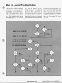
Logical Troubleshooting
The goal of logical troubleshooting
is to isolate the defective area in the
instrument in as few steps as possible. Getting started involves asking three questions:
1. What is the product supposed
to do? This may seem simpleminded but it will help you select
t h e required troubleshooting
equipment.
2. Does the product do what it was
designed to do? In other words, was
the customer trying to make the
instrument do something it was
not designed to do?
The next step was to see if anyoneelse
had experienced the same problem.
We could either ask other techs in the
area,or seeifthe problem waslistedin
the service manual - it was listed.
We had now completed several preliminary steps in the logical troubleshooting process (see accompanying box). We had:
- Verified the product was not doing
what it is supposed to do.
- Milked the insides and front panel
for clues.
- Looked to see if the problem
was common enough t o be
documented.
3. Have you or anyone else seen the
problem before? Or, is the symptom
listed in the service manual? Many
times there is a list of troubles and
probable causes in the manual’s
troubleshooting/service section.
The next logical step is to milk the
instrument for all symptoms available. Use your eyes, ears and nose.
Then you want to bracket the problem, which is simply a means of establishing broad limits around the
areas to be tested. This usually involves the next step which is halfsplitting.
Half-splitting involves making
checks a t the midpoints of the
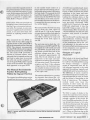
Explanation. This DVM is electrically
and physically divided into two major
sections (with two major printed circuit boards). The inguard section,
which consists of the measuring circuitry, a controller, and power
supplies; and the outguard section,
which consists of most logic circuits
and their power supplies. The outguard circuits function as the internal
main controller, HP-IB interface, and
front panel interface of the instrument (see Figure 2).
remaining parts of the circuit that
have not yet been checkeduntil you
find the faulty portion of the
circuit.
In conjunction with half-splitting
you will want to use the information funnel approach; i.e., deciding
what type of check to make that is
most appropriate to the size of the
trouble brackets at a given time.
Performing the checks in this funnel sequence assures you wide coverage of trouble possibilities
initially, but with low precision.
Then, gradually, as you proceed to
localize the trouble, the checks become more precise.
The Manual Recommends a
Second Working DVM for
Effective Half-Splitting
Both the inguard and outguard sections have their own separate microprocessor controllers that handshake
back and forth. Both sections are interconnected through a single cable
that can be easily unplugged. The
manual troubleshooting procedure
recommends using a test cable (available from HP) and a second, functional 3455 DVM. The test cable is
The Service Manual’s
Troubleshooting Section
Helps Us Bracket the
Problem
The manual’s troubleshootingsection
told us to first verify that the raw
power supplies were working properly, Mike checked and the power
supplies were fine.
The next troubleshooting step told us
to half-split the instrument since
either of its two main sections could
hang up the turn-on sequence.
2
Figure 2. This complex DVM can be easily half-split where the inguard and wtguard Sections
are interconnected at pdnt
BENCH BRIEFS JANUARY-FEBRUARY 1982
8.
WWW.HPARCHiVE.COM