1
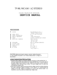
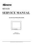
PTV3606
SERVICE MANUAL
COLOR TELEVISION RECEIVER
ORIGINAL
MFR’S VERSION A
Design and specifications are subject to change without notice.
WHEN REPLACING EEPROM (MEMORY) IC
If a service repair is undertaken where it has been required to change the MEMORY IC, the following steps should be taken to
ensure correct data settings while making reference to TABLE 1.
INI
+0
+1
+2
+3
+4
+5
+6
+7
+8
+9
+A
+B
+C
+D
+E
+F
00
---
00
00
00
00
19
60
40
00
41
00
01
03
00
00
00
10
10
00
80
80
80
00
00
---
---
---
---
---
---
---
---
---
Table 1
1. Enter DATA SET mode by setting VOLUME to minimum.
2. While holding down VOLUME button on front cabinet, press key 6 on remote control for more than 2 seconds.
ADDRESS
DATA
INIT 01 00
CRT ON 0000
Fig. 1
3. ADDRESS is now selected and should "blink". Using the VOL. +/- button on the remote, step through the ADDRESS until
required ADDRESS to be changed is reached.
4. Press ENTER to select DATA. When DATA is selected, it will "blink".
5. Again, step through the DATA using VOL. +/- button until required DATA value has been selected.
6. Pressing ENTER will take you back to ADDRESS for further selection if necessary.
7. Repeat steps 3 to 6 until all data has been checked.
8. When satisfied correct DATA has been entered, turn POWER off (return to STANDBY MODE) to finish DATA input.
After the data input, set to the initializing of shipping.
9. Turn POWER on.
10.While holding down VOLUME button on front cabinet, press key 1 on remote control for more than 2 seconds.
11.After the finishing of the initializing of shipping, the unit will turn off automatically.
The unit will now have the correct DATA for the new MEMORY IC.
ELECTRICAL ADJUSTMENTS
1. BEFORE MAKING ELECTRICAL
ADJUSTMENTS
2. BASIC ADJUSTMENTS
Read and perform these adjustments when repairing the
circuits or replacing electrical parts or PCB assemblies.
1. Place the set with Aging Test for more than 15 minutes.
2. Receive the UHF (63 ± 1dB).
3. Connect the digital voltmeter between the TP002 and
the (GND) of TU001.
4. Activate the adjustment mode display of Fig. 1-1 and
press the channel button (01) on the remote control to
select "RF AGC".
5. Press the VOL. UP/DOWN button on the remote control
until the digital voltmeter is 2.10 ± 0.05V.
2-1: AGC VOLTAGE
CAUTION
• Use an isolation transformer when performing any
service on this chassis.
• Before removing the anode cap, discharge electricity
because it contains high voltage.
• When removing a PCB or related component, after
unfastening or changing a wire, be sure to put the wire
back in its original position.
• When you exchange IC and Transistor for a heat sink,
apply the silicon grease (YG6260M) on the contact
section of the heat sink. Befor applying new silicon
grease, remove all the old silicon grease. (Old grease
may cause damages to the IC and Transistor.)
Prepare the following measurement tools for electrical
adjustments.
1. Oscilloscope
2. Digital Voltmeter
3. Pattern Generator
NOTE: Adjust after performing CUT OFF adjustment.
1. In the condition of NO indication on the screen.
Press the VOL. DOWN button on the set and the
Channel button (9) on the remote control for more than
2 seconds to appear the adjustment mode on the
screen as shown in Fig. 1-1.
TV
35 H. POSI OSD
128
Fig. 1-1
2. Use the Channel UP/DOWN button or Channel button
(0-9) on the remote control to select the options shown
in Fig. 1-2.
3. Press the MENU button on the remote control to end
the adjustments.
FUNCTION
CUT OFF
RF AGC
AGC GAIN
R DRIVE
R CUT OFF
G DRIVE
G CUT OFF
B DRIVE
H POSI 50
V POSI 50
V POSI 60
V SIZE 50
V SIZE 60
VCO COASE
VCO FINE
BRIGHT CENT
BRIGHT MAX
BRIGHT MIN
1. Place the set with Aging Test for more than 15 minutes.
2. Using the remote control, set the brightness and contrast
to normal position.
3. Activate the adjustment mode display of Fig. 1-1 and
press the channel button (00) on the remote control to
select "CUT OFF".
4. Adjust the Screen Volume until a dim raster is obtained.
2-3: WHITE BALANCE
On-Screen Display Adjustment
NO.
00
01
02
03
04
05
06
07
08
09
10
11
12
13
14
15
16
17
18
19
2-2: CUT OFF
NO.
20
21
22
23
24
25
26
27
28
29
30
31
32
33
34
35
36
37
38
39
FUNCTION
TINT
SHARP
CONT CENT
CONT MAX
CONT MIN
COLOR CENT
COLOR MAX
COLOR MIN
M R CUT OFF
M G CUT OFF
M B CUT OFF
CVBS OUT
APR THR
BELL
BANDPASS
H POSI OSD
V POSI OSD
H POSI TXT
V POSI TXT
H POSI 60
1. Place the set with Aging Test for more than 10 minutes.
2. Receive the white 100% signal from the Pattern
Generator.
3. Using the remote control, set the brightness and contrast
to normal position.
4. Activate the adjustment mode display of Fig. 1-1 and
press the channel button (04) on the remote control to
select "R CUT OFF".
5. Using the VOL. UP/DOWN button on the remote control,
adjust the R CUT OFF.
6. Press the CH. UP/DOWN button on the remote control
to select the "R DRIVE", "G DRIVE", "G CUT OFF" or
"B DRIVE".
7. Using the VOL. UP/DOWN button on the remote control,
adjust the R DRIVE, G DRIVE, G CUT OFF or B DRIVE.
8. Perform the above adjustments 6 and 7 until the white
color is looked like a white.
2-4: FOCUS
1. Receive the monoscope pattern.
2. Turn the Focus Volume fully counterclockwise once.
3. Adjust the Focus Volume until picture is distinct.
2-5: CONSTANT VOLTAGE
1. Place the set with Aging Test for more than 15 minutes.
2. Using the remote control, set the brightness and contrast
to normal position.
3. Connect the digital voltmeter to TP501.
4. Set condition is AV MODE without signal.
5. Adjust the VR501 until the digital voltmeter is 135 ± 0.5V.
2-6: VERTICAL LINEARITY
1. Receive the monoscope pattern.
2. Using the remote control, set the brightness and
contrast to normal position.
3. Adjust the VR420 until the SHIFT quantity of the OVER
SCAN on upside and downside becomes minimum.
Fig. 1-2
ELECTRICAL ADJUSTMENTS
2-7: HORIZONTAL POSITION
2-11: COLOR CENT
1. Receive the monoscope pattern.
2. Using the remote control, set the brightness and
contrast to normal position.
3. Activate the adjustment mode display of Fig. 1-1 and
press the channel button (08) on the remote control to
select "H POSI(50)".
4. Press the VOL. UP/DOWN button on the remote control
until the SHIFT quantity of the OVER SCAN on right
and left becomes minimum.
5. Receive the monoscope pattern of NTSC.
6. Using the remote control, set the brightness and
contrast to normal position.
7. Activate the adjustment mode display of Fig. 1-1 and
press the channel button (39) on the remote control to
select "H POSI(60)".
8. Press the VOL. UP/DOWN button on the remote control
until the SHIFT quantity of the OVER SCAN on right
and left becomes minimum.
1. Receive the color bar pattern. (RF Input)
2. Connect the oscilloscope to TP023.
3. Using the remote control, set the brightness, contrast
and color to normal position.
4. Activate the adjustment mode display of Fig. 1-1 and
press the channel button (25) on the remote control to
select "COLOR CENT".
5. Adjust the VOLTS RANGE VARIABLE knob of the
oscilloscope until the range between white 100% and
0% is set to 5 scales on the screen of the oscilloscope.
6. Press the VOL. UP/DOWN button on the remote
control until the red color level is adjusted to 85 ± 10%
for the white level. (Refer to Fig. 2-2)
7. Receive the color bar pattern. (Audio Video Input)
8. Press the AV button on the remote control to set the AV
mode. Then perform the above adjustments 2~6.
2-8: VERTICAL SIZE
1. Receive the monoscope pattern.
2. Using the remote control, set the brightness and
contrast to normal position.
3. Activate the adjustment mode display of Fig. 1-1 and
press the channel button (11) on the remote control to
select "V SIZE(50)".
4. Press the VOL. UP/DOWN button on the remote control
until the SHIFT quantity of the OVER SCAN on upside
and downside becomes 8 ± 3%.
5. Receive the monoscope pattern of NTSC.
6. Using the remote control, set the brightness and
contrast to normal position.
7. Activate the adjustment mode display of Fig. 1-1 and
press the channel button (12) on the remote control to
select "V SIZE(60)".
8. Press the VOL. UP/DOWN button on the remote control
until the SHIFT quantity of the OVER SCAN on upside
and downside becomes 8 ± 3%.
2-9: BRIGHT CENT
1. Place the set with Aging Test for more than 15 minutes.
2. Receive the monoscope pattern. (RF Input)
3. Using the remote control, set the brightness and
contrast to normal position.
4. Activate the adjustment mode display of Fig. 1-1 and
press the channel button (17) on the remote control to
select "BRIGHT CENT".
5. Press the VOL. UP/DOWN button on the remote control
until the white 25% is starting to be visible.
6. Receive the monoscope pattern. (Audio Video Input)
7. Press the AV button on the remote control to set to the
AV mode. Then perform the above adjustments 3~5.
2-10: CONT CENT
1. Place the set with Aging Test for more than 15 minutes.
2. Activate the adjustment mode display of Fig. 1-1 and
press the channel button (22) on the remote control to
3. select "CONT CENT".
4. Press the VOL. UP/DOWN button on the remote control
until the contrast step No. becomes "30".
5. Press the AV button on the remote control to set the AV
mode. Then perform the above adjustments 1, 2.
85%
100%
Fig. 2-2
2-12: VCO COASE/VCO FINE
1. Connect the oscillator (39.5MHz) to between the TP003
and the (GND) of TU001.
2. Activate the adjustment mode display of Fig. 1-1 and
press the channel button (13) on the remote control to
select "VCO COASE".
3. Press the VOL. UP/DOWN button on the remote control
until the "+" appear on the screen.
4. Press the CH UP button once to set to "VCO FINE"
mode.
5. Press the VOL. UP/DOWN button on the remote control
to select the 4 step down point from the upper limit on
the "+".
(Example: In case of the "+" point 30~41, select 37.)
2-13: VERTICAL POSITION
1. Receive the monoscope pattern.
2. Using the remote control, set the brightness and
contrast to normal position.
3. Activate the adjustment mode display of Fig. 1-1 and
press the channel button (09) on the remote control to
select "V POSI(50)".
4. Check if the step No. V. POSI is "08".
5. Adjust the VR401 until the horizontal line becomes fit
to notch of the shadow mask.
ELECTRICAL ADJUSTMENTS
2-14 : Confirmation of Fixed Value (Step No.)
Please check if the fixed values of the each adjustment
items are set correctly referring below.
NO.
02
04
06
07
10
18
19
20
21
23
24
26
27
30
31
32
33
34
35
36
37
38
FUNCTION
AGC GAIN
R CUTOFF
G CUTOFF
B DRIVE
V POSI 50/60
BRIGHT MAX
BRIGHT MIN
TINT
SHARP
CONT MAX
CONT MIN
COLOR MAX
COLOR MIN
MB CUTPOFF
CVBS OUT
APR THR
BELL
BANDPASS
H POSI OSD
V POSI OSD
H POSI TXT
V POSI TXT
RF
00
00
00
31
08
37
10
32
04
50
10
39
14
80
16
04
10
06
128
50
122
58
AV
----------37
10
32
04
50
10
39
14
-------------------
BLOCK DIAGRAM
J1001
HEADPHONE_JACK
2
TU001
SDA SCL
4
5
9
CH UP
IF
11
CHROMA IC
IC201 STV2246C
AGC
1
VIF PRE. AMP
VOL UP
3 A_MUTE
56 KEY IN
OS101
CF202
SAW FILTER 5
4
6
35
OSD_G
OSD_B 15
34
OSD_B
37
OSD_BK
42
X1/VAMP/CHR_OUT
B.OUT 48
30
25
B_EXT/U_EXT
31
G.OUT 49
51
SCL
52
SDA
20
CVBSIN2
28
BLK_EXT
27
R_EXT/V_EXT
26
G_EXT/Y_EXT
MEMORY IC
IC199 S-24C04BFJ-TB
SCL 20
6
SCL
SDA 19
5
SDA
X101
4 MHz
2 RESET OSC_OUT 50
V-SYNC 41
4
9
XTAL1
4
8
SOUND AMP
IC
SP1001
SPEAKER
5
6
40
X601
4.433619MHz
VERT
OSC IN 51
9V REG. IC
IC503 KIA7809API
2
INT_CVBS_OUT 13
PIFIN1
OSD_G 16
55 POWER FAIL
1
CVBSIN1 18
PIFIN2
7
OSD_R
10 POWER
RESET IC
IC102 PST3231NR
11
36
Q510, Q511
P.CON SW.
55
FM_OUT
OSD_R 17
1 REMORT OSD_FB 18
1
1
1
MICON W/T.TEXT IC
IC101 OECF009A
VOL DOWN
AUDIO_OUT
RF_AGC_OUT
8
Q201
CH DOWN
3
IC1001 AN7511
47
H.OUT
48
R.OUT
32
EXT_AUDIO_IN 14
BCL/SAF 46
H-SYNC 40
STAND BY LED
Q802
RED OUT
1
Q506
D101
Q103
P.FAIL
Q801
GREEN OUT
Q803
LED DRIVE
Q501
IC401 TDA8174A
POWER
Q402
D501~D504
REG. 6V IC
IC502 KIA7806API
RECTIFIER
3
9
7
B
G
R
F
8
Heater
H. DRIVE
V-DRIVE IC
V801
CRT
BLUE OUT
4
Q401
1
Q502
T501
15
13
4
POWER
3
6
10
2
H. OUTPUT
1
17
DY
5
IC504 LTV-817M-VB
J701
3
FEED BACK
2
6
16
1
15
3
8
Q507
L503
DEGAUSS COIL
L501
FEED BACK
SWITCHING
11
7
FB401
19
3
20
1
7
AC IN
2
1
4
3
2
10
F
FBT
S
HV
5
F501
E-1
E-2
A
B
C
D
E
F
G
H
MICON/TUNER SCHEMATIC DIAGRAM
UE25-B58D
TU/RGB
(BBE-H)
(ATS)
PROTECT
P3.5
P3.4
V_SYNC
OSD_G
H_SYNC
OSD_R
0.2
39
0
OSD_FB
AVDD1
37
PXFM
SDA
JTRSTO
SCL
36
VDD
35
AGND
JTDO
34
33
CVBS2
32
JTMS
AVDD3
31
R111
HS101
763WSA0087
2.1
13
C006
100P CH
50V 1 KA
R006
15K
C003
100K
R005
100
3.8
R004
100
0.01 F
R003
10uH 0305
C007_1
4.9
L001 6.3V 470 YK
NC
NC
4.0
12
2
1 AGC
3 ADRES
4 SCL
5 SDA
6 V.S
7 BPL
8
9 BTL
R002
5
18K 1/2W
18K 1/2W
10K
10K
2
4
B
1
C139_1
C120
7
R142
1K
8
R143
1K
9
AVDD2
TEST0
WSCF
VPP
FROM/TO CHROMA/SIF/VIF/21PIN
2.5
NC
VIDEO_OUT
RF_AGC
R128
OSD_B
100 1/4W
R129
10
OSD_G
OSD_R
100 1/4W
L101
C114
0.1
OSD_FB
C115
6.3V
SCL
10uH 0305
B
SDA
1000 YK
CVBS_TXT
R114
HD
4.7K
R115
0
PROTECT
FOR_VCR
MCFM
TXCF
JTCK
15K
4.8
NC
0.1
F R113
5.6K
VCC
1
0
2
7
4.6
6
MODE
8
C118_1
4.6
5
SDA
0
SCL
4.9
4.9
CVBSO
3
V_OUT
4.7K
4.9
1.6
4
IF
VSS
C106
1K
E2
0.1 B
1.8K
R141
PROTECT
E1
0.6
NC
R147
6
E0
4.9
C105
0.022 B
4.7
NC
1.8K
1K
MEMORY IC
IC199
S-24C04BFJ-TB
68P CH
R146
R140
0.1 B
82P CH
1.8K
C119
C112
C101
R145
TO DEFLECTION/CRT
5
0
30
270 1/4W
4
1.8K
4.9
GND
CVBS1
29
1.8
R144
4.6
0.47 B
R108
10K
C116
W801
3
R135
4.6
0
1.6
A_MUTE
10K
16
0.2
0
C111
1
0.7
OSD_B
TO SOUND AMP
R134
14
AV2
5
10K
0.0047 B
2.0
POWER
R125
4.9
NC
0
0
22P CH
0.1 B
C104
R110
0.0047 B
5.6K
C103
16V 10 KA
C102
C131_1
CH
GND
12
I2C_OFF
AT+5V_DVDD
10K
13
H_CONT
AV1
38
C121
68P
AT+5V_AVDD
R148
4.9
1SS133
4.9
P.FAIL
C113
0.6
10K
TUNER_BT
22P CH
3
6
11
CSO/RESET0/P3.7
TUNER HI
17
D108
5
VIDEO OUT
15
44
43
4.7
R116
4
RF AGC
P.CON+5V
10
47
0
42
1/4W
4
POWER
41
MTZJ5.1B
SECAM_VL_H
40
1K
D102
1/4W
NC
4.8
10K
2
R107
R138
4.7K
9
STANDBY LED
P4.6/PWM6
0
R124
3
I2C OFF
NC
0.2
0
10K
2
I2C SDA
FROM/TO POWER
8
ON_TIMER
0
R123
NC
1.6
45
10K
7
OSC_OUT
0
R133
NC
1
75 1/4W
18
5.0
NC
GND
GND
I2C SCL
6
0
46
NC
6
OSC_IN
0
5
0
R122
19
22P CH
CP101
06JQ-ST
20
4.9
NC
VCC
100
0
TEST POINT
NC
21
C109
7
NC
22
4.8
NC
DEGAUSS
23
1
R106
R001
52
2.3
EMERGENCY
0
51
1.9
4.7K
X101
100CT4R013
4MHz
50
22P CH
49
R152
48
C108
NC
ANT001
TU-33AP
BT002
R03(AB)2PXGPI
TM101
RC-GE030
0
0
6
NC
BT001
R03(AB)2PXGPI
CP001
003P-2100
R121
3
STEREO RESET
4.7K
0.47 F
FORTHD VCR 1
4.9
NC
RESET
ACCESSORY
AGC
TP002
4.9
24
0.1 F
0
25
C141_1
53
0
R151
4
A MUTE
FORTHD VCR 2
3
0
5
54
10K
4.9
2
RESET
POWER FAIL
0
R117
220P B
1
56
4.9
26
4.7K
C140_1
RESET IC
IC102
PST3231NR
REMORT
KEY_IN
27
4.9
28
R120
4.9
55
4.9
R105
MICON W/T.TEXT IC
IC101
OECF009A
C002
NC
0.022 B
30.7
14
0
D001
16V 10 KA
MTZJ33B
3 B+
4.9
C122
STAND BY
D101
SLR-342VCT32
1.5K
1/4W
R112
7
0
C001
4.9
560
10
11 IF
15
3.1
2.4
75
3.1
R132
R007
2.2K
R109
EVQ21505R
VOL UP
SW103
RED LED DRIVE
Q103
2SA1037AK
VCO
TP003
NC
47
1/4W
390
2 GND
820
1 Vout
1.2K
R126
2.2K
VOL DOWN
SW104
R101
EVQ21505R
R102
EVQ21505R
R103
CH DOWN
SW102
EVQ21505R
CH UP
SW101
OS101
RPM7138-H5
R104
8
NC
2.2
TU001
NC
(MAIN PCB)
8
2
3
0
0
4
0
2
L102
10uH 0305
PCB010
TMB557
1
NOTE: THIS SCHEMATIC DIAGRAM IS THE LATEST AT THE TIME
OF PRINTING AND SUBJECT TO CHANGE WITHOUT NOTICE
A
G-1
B
PIECES REPAREES PAR UN
ETANT
ATTENTION:LES
DANGEREUSES AN POINT DE VUE SECURITE
NOTE:THE DC VOLTAGE AT EACH PART WAS MEASURED
WITH THE DIGITAL TESTER WHEN THE COLOR BROADCAST
WAS RECEIVED IN GOOD CONDITION AND PICTURE IS NORMAL.
C
THESE PARTS MARKED BY
CAUTION:SINCE
CRITICAL FOR SAFETY,USE ONES
N’UTILISER QUE CELLS DECRITES
DANS LA NOMENCLATURE DES PIECES
D
E
1
ARE
DESCRIBED IN PARTS LIST ONLY
F
G
H
G-2
A
B
C
D
E
F
G
H
CHROMA/SIF/VIF/21PIN SCHEMATIC DIAGRAM
(MAIN PCB)
11
VCO COIL
L207
3700005
1K
R203
1.2K
1K
R219
CF201
BUFFER
Q202
2SC2412K
2.2
13
TPSRA6M00B00-A0
390
R204
L202
7.9
2.9
R217
3.3uH 0305
C203_1
0.022 F
P.CON+8V
R621
W823
L204
18uH
SAW FILTER
CF202_1
J1951M
IN IN G OUTOUT
1 2 3 4 5
82
R201
0.8
10 KA
560 1/4W
560
L203
1.5uH
R202
R215
16V
C212_1
VIF PRE.AMP
Q201
KTC3881S-RTK
1.5
B
R214
CF204
FROM POWER
MKT41.5MA110P
0.001
2.2K
0.27uH
6
6.8K
C204
1K
0.01 F
7.0
7
C629
3.2
R208
L206
SIF BUFFER
Q204
2SC2412K
5.0
3.9
6
7
8
4
R213
100 1/2W
8
14
6
470P B
1
2
3
4
C701
5
20
21
22
23
24
25
26
27
28
10K 1/4W
NC
R707
1K 1/4W
5
7
R703
1K 1/4W
8
19
9
18
10
17
11
16
6
R706
R715
NC
R713
13
75
12
15
BLK_EXT
0.1 B
14
R_EXT/V_EXT
0.1 B
C623
13
G_EXT/Y_EXT
0.1 B
C622
C608
R714
75
12
CHROMA IC
21PIN
J701
0350_9982_05
470P B
L703
R719
100K
330K
R622
F
1
10uH
1/4W
0
B_EXT/U_EXT
3.4
APR
3.6
CHR
3.4
Y/CVBS_IN3
1.7
BS
2.8
CVBSIN2
3.2
GND2
0
CVBSIN1
4.1
L702
3.3K
10uH
C703_1
F
1
75
C602
R625
50V 1 KA
C603
C220
10V 470 YK
1 KA
50V
C210
7.8
(8V) VCC2
11
3.9
C607
B
C221
0.1
1
2
3
50V 22 YK
C216
10
3.8
100
PIF_LC2
PIFIN1
9
2.4
NC
1.7
3.2
PIF_LC1
AGCPIF_CAP
8
3.8
R720
NC
R702
18
EXT_AUDIO_IN
VREF_IF
7
4.9
17
INT_CVBS_OUT
6
3.6
16
(5V) VCC_IF
5
0
FM_OUT
4
2.0
GND_IF
3
4.5
IFPLL
2
2.5
RF_AGC_OUT
1
AGCSIFCAP
2.5
SIFIN2
2.7
SIFIN1
STV2246C
3.1
12
PIFIN2
NC 2.7 NC 2.8 NC 4.8
NC
C201
3P CH
L103
10uH
5
D601
1SS133
0.1 B
16V 47 YK
C215
C217
C205
R218
C202
0.001 B
C207
F
1
0.001 B
150
C218
0.022 B
C209
16V 10 KA
C213_1
P.CON+5V
0.33 B
GND
14
75
VCC_D (5V)
SDA
SCL
SLPF
LBF/SSC
H_OUT
VERT
BCL/SAF
VCC1 (8V)
NC
GND1
X1/VAMP/CHR_OUT
CLPF
XTAL1
XTAL2
XTAL3
OSD_BK
OSD_R
OSD_G
OSD_B
ICATH
R.OUT
G.OUT
B.OUT
CVBSOUT
53
52
51
50
49
48
47
46
45
44
43
42
41
40
39
38
37
36
35
34
33
32
31
30
29
4.8
4.5
1.7
1.7
2.6
270
4.2
270
R630
4.1
270
R629
0
R628
100CT4R408
4.433619MHz
19
20
16
18
75
R221
4.4
20
75
W4BRH3.5X6X1.0
8.3
D709
4.6
21
4
19
B1002
21
BUFFER
Q605
2SC2412K
4.0
1K
R623
FROM/TO DEFLECTION/CRT
10K
MTZJ6.8B
R618
MTZJ6.8B
D608
MTZJ6.8B
D607
D606
47K
MTZJ5.1B
R636
X601
0.2
0.1 B
NC
C618
0
0.0047 B
C615
NC
0.1 B
C620
2.2
47K
R608
2.4
0.1 B
C619
17
R709
1 B
C616
F
1
1K
2.8
0
10V 470 YK
NC 5.0
C613
7.8
C614_1
5.4
27K
24
4.6
C624_1
2.0
0.01
F
R640
5.2
2.2K
4.2
R638
47P CH
50V 3.3 KA
R607
5.0
C612
5.0
C625
C609
1 F
C605_1
AUDIO_OUT
4.9
C611
0
16V 100 YK
C601 47P CH
4.5
0.1 B L601
10uH
C610
0305
1.5
TO SOUND AMP
470
GND_D
54
2.2K
R643
AUDIO_OUT
55
0.0015 B 22K
R645
FM_CAP
56
IC201
4
15
R708
B.OUT
100
SCL
HD
PROTECT
0.0
ABCL
MTZJ5.6B
D609
VAMP
AFC
V_OUT
D604
2.7K
11E1-EIC
FROM/TO MICON/TUNER
23
VIDEO_OUT
ACL CANCEL
Q615
KRC102SRTK
FOR_VCR
R647
V_OUT
R648
2
16V 22 KA
R644
8.2
0.0
C634
5.6K
R646
D602
SDA
ACL CANCEL
Q616
KRA102SRTK
8.2K 1/4W
R639
5.3
3
H_OUT
1SS133
8.2
RF_AGC
R.OUT
1SS133
D603
8.2
1K
R601
IF
100
R606
R602
G.OUT
FROM/TO MICON/TUNER
3
560 1/2W
CVBS_TXT
OSD_B
330
2
OSD_G
OSD_R
OSD_FB
PCB010
TMB557
A
G-3
NOTE:THE DC VOLTAGE AT EACH PART WAS MEASURED
WITH THE DIGITAL TESTER WHEN THE COLOR BROADCAST
WAS RECEIVED IN GOOD CONDITION AND PICTURE IS NORMAL.
NOTE: THIS SCHEMATIC DIAGRAM IS THE LATEST AT THE TIME
OF PRINTING AND SUBJECT TO CHANGE WITHOUT NOTICE
1
B
C
D
CAUTION: DIGITAL TRANSISTOR
CAUTION: DIGITAL TRANSISTOR
1
E
F
G
H
G-4
A
B
C
D
E
F
G
H
SOUND AMP/FRONT AV SCHEMATIC DIAGRAM
(MAIN PCB)
8
8
7
7
6
6
29
3.5
6
0
3.4
7
8
+
5
4
3
5.1
-
2
0
SOUND AMP IC
IC1001
AN7511
8.2
5
1
0.3
CP1001
TID-X02P-B2
BLACK
2
RED
1
3.9
R1011
C1002
47K 1/4W
5
SPEAKER
2
1
47P CH
FROM CHROMA/SIF/VIF/21PIN
SP1001
SA08A05BWC
2
C1009
C1007
R1010
16V 10 KA
33 1/2W
3
0.0047 B
47K
R1006
0.0022
B1001
W4BRH3.5X6X1.0
C1004
50V 1 KA
FROM POWER
C1005_1
100K
R1003
C1001
4
16V 470 YK
B
AUDIO_OUT
HEADPHONE_JACK
J1001
MSJ-035-12A_PC
4
1
GND
C1003
68K
R1009
SOUND+B
3
R1004
KA
47K 1/4W
16V 10
FROM DEFRECTION
3
FROM MICON/TUNER
A_MUTE
2
2
PCB010
TMB557
1
NOTE: THIS SCHEMATIC DIAGRAM IS THE LATEST AT THE TIME
OF PRINTING AND SUBJECT TO CHANGE WITHOUT NOTICE
A
G-5
B
NOTE:THE DC VOLTAGE AT EACH PART WAS MEASURED
WITH THE DIGITAL TESTER WHEN THE COLOR BROADCAST
WAS RECEIVED IN GOOD CONDITION AND PICTURE IS NORMAL.
C
PIECES REPAREES PAR UN
ETANT
ATTENTION:LES
DANGEREUSES AN POINT DE VUE SECURITE
N’UTILISER QUE CELLS DECRITES
DANS LA NOMENCLATURE DES PIECES
D
E
THESE PARTS MARKED BY
CAUTION:SINCE
CRITICAL FOR SAFETY,USE ONES
ARE
1
DESCRIBED IN PARTS LIST ONLY
F
G
H
G-6
A
B
C
D
E
DEFLECTION/CRT SCHEMATIC DIAGRAM
F
CP802A
B2013H02-6P
8
H
CP802B
B2013H02-6P
PROTECT
1
1
PROTECT
CUT OFF
CUT OFF
2
2
GND
3
3
GND
R.OUT
R.OUT
4
4
R.OUT
G.OUT
G.OUT
5
5
G.OUT
B.OUT
B.OUT
6
6
B.OUT
FROM/TO CHROMA/SIF/VIF/21PIN
G
(MAIN PCB)
8
VAMP
GND
6
0
D809
1SS133
D808
1SS133
R814
1.2K 1/4W
270
270
C806
470P B
C805
R816
1/4W
1.2K
R811
R815
2.7
470P B
270 1/4W
R813
95.4
6
YK
C448
250V 10
R409
V_POSI
VR401
2.2K
680 1/2W
5
3
NC
2
1
9
10
8
6
11
40
R
G
B
39
41
R806
5
2.7K 1/4W
R807
15K 1W
R804
2.7K 1/4W
R805
15K 1W
R802
R803
5 7 1
CP401
A1561WV2-A5P
15K 1W
R403
4
1K 1/2W
R416
2.2 1/2W
25V 2200 MHE
V801
A34JXV70X53N45
(CPJ370BVBK1U-TC)
R447
68 1/2W
CMPP
0.0082
0
2.7
3.2
ANODE
C443
100 1/4W
HS402
763WSA0017
L401
250V 2.2 MHE 4.7mH 0909
H.OUTPUT
38
Q401
TT2140LS-YBC11
130
R427
C440
H.DRIVE
Q402
2SC1627_Y
50V 22 YK
R446
0
C423
37
98.4
BLUE OUT
Q803
KTC3207
1.25KV
4
0.3
100V 0.01 MMTS 470 1/2W
C446
11E1-EIC
D406
P.CON+8V
180 1W
R424
FROM POWER
27.0
1
250V 0.39 PMS
4
7
(to CP001)
C437
2
1
1
2.7
470P CH
R410
680 1/2W
CP801
003P-2100
CD801
SM1573-001
C804_1
C403
100.6
3.2
2.7K 1/4W
3
RED OUT
Q802
KTC3207
3.2
35
100V 0.22 MMTS
C422
R407
T401
ETH09K14BZ
1.2K 1/4W
FROM/TO DEFLECTION
5
36
NC
180V
1
1.2 1/2W
C418
470
50V 10 YK 1.2K
HS401
763WSAA013
D807
4
1SS133
3
4
10K 1/4W
C417
R422
1.5K 1/4W
V_LIN
VR420
1/4W
R417
6.8K
R419
PROTEC
Q403
KRC102SRTK
0.0
3
35V 470 YK
R402
D403
R420
3.3K +-1% M
0.0
PROTECT
HEATER
FROM/TO CRT
11E1-EIC
R406
GND
2
GREEN OUT
Q801
KTC3207
FROM MICOM/TUNER
2.2
1
2
180V
1.7
34
6
1
R809
R429
5.6 1W
11
25.0
1K 1/2W
10
4.4
GND
HEATER
W815
FB. GENERATOR
Vs
INVERTING INPUT
9
12.0
CP803B
B2013H02-4P
NC
35V 100 YK
C412
16V 10 KA
8
12.0
C414
7
0.0
8.2K 1/4W
6
4.4
BUFFER OUTPUT
RAMP GENERATOR
GND
5
6.4
0.047 MMTV
R412
4
5.0
CP803A
B2013H02-4P
C413
0.082 B
33
Vref. DECOUP.
HEIGHT ADJ.
3
23.0
TDA8174A
390K +-1% M
C408
2
14.5
1K 1/4W
R405
OUTPUT STAGE Vs
1
IC401
R408
R404
AFC
330K +-1% M
H_OUT
7
POWER OUTPUT
ABCL
TRIGGER INPUT
V-DRIVE IC
V_OUT
H.DRV+B
4
+B
B_SHORT
FOCUS
SCREEN
C819
SCREEN
SOUND+B
2KV 0.001 B
CP806_1
220P CH
C401
TO SOUND AMP/FRONT AV
FOCUS
96.4
B+
2W
D410
11E1-EIC
AU02A-EIC
AFC
ABL 5.6
7
HEATER 6.3
10
NC 9
8
GND
4.9
5
E25
NOTE: THIS SCHEMATIC DIAGRAM IS THE LATEST AT THE TIME
OF PRINTING AND SUBJECT TO CHANGE WITHOUT NOTICE
47K 1/4W
C435
11E1-EIC
D414
220K 1/4W
R421
R445
AU02A-EIC
10V 470 YK
3W
PCB010
TMB557
A
B
C
D
NOTE:THE DC VOLTAGE AT EACH PART WAS MEASURED
WITH THE DIGITAL TESTER WHEN THE COLOR BROADCAST
WAS RECEIVED IN GOOD CONDITION AND PICTURE IS NORMAL.
NOTE: THE RESISTOR MARKED F IS FUSE RESISTOR.
THE ALUMI ELECTROLYTIC CAPACITOR MARKED NP
IS NON POLAR ONE.
1
G-7
F
9
8
D404
C404
6.8
2
GND
3
R418_2
99.6
PCB110
TCB416
16.8
E12
NC 4
2
0
100V 0.1 MMTS
150
D407
3
J801
ISMS01S
GND
11
2
R411_2
1
5
F
S
135
0
6
0
101.6
135 VIDEO
6
4
0
25.2
HV
COL
7
1
8
D405
AU02A-EIC
131.7
3
FNI-14B002
3
6.4
FB401_1
E
F
PIECES REPAREES PAR UN
ETANT
ATTENTION:LES
DANGEREUSES AN POINT DE VUE SECURITE
CAUTION: DIGITAL TRANSISTOR
N’UTILISER QUE CELLS DECRITES
DANS LA NOMENCLATURE DES PIECES
THESE PARTS MARKED BY
CAUTION:SINCE
CRITICAL FOR SAFETY,USE ONES
ARE
1
DESCRIBED IN PARTS LIST ONLY
G
H
G-8
A
B
C
D
E
F
G
H
POWER SCHEMATIC DIAGRAM
(MAIN PCB)
8
8
TO SOUND AMP/FRONT AV
GND
7
7
TO DEFLECTION/CRT
GND
C517
P.CON+8V
2KV 0.001 R
D510
W812
+B
RU2AM-EIC
5
0
14
D513
21DQ09N
0
16
2
13.06
17
1
0
18 NC
SW
D511
R526
R507
1N4937
100 1/4W
2.2K
MTZJ12B
R508
4.2
10K
B
C
W825
POWER
5.1
C508
R524
SB140-EIC
SB140-EIC
D515
D512
0.1
P.CON SW
Q510
KRC103SRTK0
4.7
3
2
1SS133
2
100
VR501
1K
R519
PCB010
TMB557
THESE PARTS MARKED BY
CAUTION:SINCE
CRITICAL FOR SAFETY,USE ONES
N’UTILISER QUE CELLS DECRITES
DANS LA NOMENCLATURE DES PIECES
1SS133
1SS133
D521
56K 1/2W
2.2K
+-1% M
D514
6.2
5.6
+B ADJ
MTZJ5.6B
560 1/4W
FEED BACK
SWITCHING
Q507
7.7
KTC3198
C513
8.1
FEED BACK
IC504
LTV-817M-VB
PIECES REPAREES PAR UN
ETANT
ATTENTION:LES
DANGEREUSES AN POINT DE VUE SECURITE
NC
D518
10V 100 YK
1SS133
560 1/4W
10K
1
4
3
0.3
5.0
4.4
C514
3
6.0
D509
HS502
763WAA0186
4
P.CON SW
Q511
KTA1281_Y
OUT
GND
IN
1K
R512
D
AT+5V_DVDD
AT+5V_AVDD
R515
D523
9.1 470 1/4W
R513
NOTE:THE DC VOLTAGE AT EACH PART WAS MEASURED
WITH THE DIGITAL TESTER WHEN THE COLOR BROADCAST
WAS RECEIVED IN GOOD CONDITION AND PICTURE IS NORMAL.
2
0
16V 1000 YK
C522
MTZJ3.6B
D528
NOTE: THIS SCHEMATIC DIAGRAM IS THE LATEST AT THE TIME
OF PRINTING AND SUBJECT TO CHANGE WITHOUT NOTICE
R532
R514
R522
D524
2
1
P.CON+5V
P.FAIL
Q506
2SA1037AK
4.9
11E1-EIC
R518
D508
B 50V 1 KA
0.01 B
D505
R510
2.2K 1/4W
680 1/4W
R511
HS501
763WAA0162
21DQ09N
C519
0.3
0
C524
POWER
Q502
KTC3203_Y
8.0
D516
12.3
0.0033 B
1W
1
R516
6.7
1
2.2K
1/4W
C518
0.01
1/4W
R523
R525
0.047 MMTV 220 1W
220
KX
470P
R502
C516_1
POWER
0.3
Q501
2SK2647-01MR
250V
KX
C527
250V 0.0022
0.001 KX
C528
C532
SW501
ESB92S22B
250V
2
FH502
EYF-52BC
G 6.7
S
MTZJ18B
NC NC
5
P.FAIL
4.9
D525
D
3
A
C533
16V 10 KA
REG.6V IC
IC502
KIA7806API
2.2K
C507
4
234.7
1SS133
3
D507
R
0.0033 B
2KV 0.001
1.5M 1/2W
FH501
EYF-52BC
G-9
FROM/TO MICON/TUNER
TUNER_BT
GND
1SS133
R501
1
L502
W5T29X7.5X19
GND
P.CON+8V
11E1-EIC
16V 10 KA
R520
P.CON+5V
C526_1
BLUE
F501
50T040H
T4A_L_250V
4
5.0
D517
3
45.9
19.1
S501B
BROWN
BLUE
0
TO CHROMA/SIF/VIF/21PIN
GND
C525
13
S501A
BROWN
8.0
6
16V 220 YK
6
9.7
MTZJ18B
4
11.2
15
0
3
163.9
W4BRH3.5X6X1.0X2
D522
2
16V 470 YK
237.7
1
F
270
OUT
7
0
12 NC
C515
C502_1
1
0
11 NC
0.47
2
3
RM11C-EIC
270
B501
275V 0.22
ECQUL
C501_2
AC230-240V_50Hz
CD501
06444801
4
275V 0.1
5
RM11C-EIC
D502
8
258.8
1W
C506_1
D504
0.22
RM11C-EIC
R517
C503
COIL LINE FILTER
L501
0R7A223F24Y
C504
2
ECQUL
1
2
CP502
A1561WV2-2P
1
R503
D501
RM11C-EIC
1.5M 1/4W
D503
H
1.5M 1/4W
2
C505
P
400V 82 USR
DEGAUSS COIL
L503
8R140018
1
2KV 0.001 B 2KV 0.001 B
3
REG.9V IC
IC503
KIA78R09API
IN
0
10 NC
C521
8129110H
160V 100 YXF
T501
B504
TH501_1
B59104-T80-B10
W851
6
W5RH3.5X5X1.0
H.DRV+B
ARE
CAUTION: DIGITAL TRANSISTOR
1
DESCRIBED IN PARTS LIST ONLY
E
F
G
H
G-10
WAVEFORMS
MICON/TUNER
0.5µs
1.00V
1
10ms
1.00V
2
20µs
1.00V
3
20µs
1.00V
4
CHROMA/SIF/VIF/21PIN
50µs
20µs
100mV
0.50V
6
50µs
100mV
7
50µs
0.50V
8
0.2ms
1.00V
9
11
2ms
200mV
12
20µs
1.00V
13
20µs
1.00V
14
50µs
0.2ms
20µs
100mV
1.00V
100mV
5
10
16
NOTE: The following waveforms were measured at the point of the corresponding
balloon number in the schematic diagram.
WAVEFORMS
20µs
10ms
10ms
1.00V
1.00V
10.0V
17
23
35
20µs
20µs
20µs
100mV
200mV
10.0V
18
24
36
SOUND AMP/FRONT AV
20µs
1.00V
500us
500mV
20µs
5.0V
19
29
37
DEFLECTION/CRT
20µs
1.00V
10ms
1.00V
2µs
200V
20
33
38
20µs
10ms
20µs
1.00V
10.0V
50V
21
34
39
NOTE: The following waveforms were measured at the point of the corresponding
balloon number in the schematic diagram.
WAVEFORMS
20µs
50V
40
20µs
50V
41
NOTE: The following waveforms were measured at the point of the corresponding
balloon number in the schematic diagram.