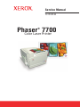
1
Service Manual
701P28180
Phaser
7700
Color Laser Printer
®
Service Manual
701P28180
Phaser®7700
Color Laser Printer
Warning
The following servicing instructions are for
use by qualified service personnel only. To
avoid personal injury, do not perform any
servicing other than that contained in
operating instructions unless you are qualified
to do so.
This printing: December 2006
Prepared By:
Xerox Corporation
XOG Worldwide Product Training and Information
26600 SW Parkway
Wilsonville, OR 97070
© 2006 by Xerox Corporation. All rights reserved.
Unpublished rights reserved under the copyright laws of the United States. Contents of this
publication may not be reproduced in any form without permission of Xerox Corporation.
Copyright protection claimed includes all forms and matters of copyrightable materials and
information now allowed by statutory or judicial law or hereinafter granted, including without
limitation, material generated from the software programs which are displayed on the screen
such as styles, templates, icons, screen displays, looks, etc.
Xerox technical training materials and service manuals are intended for use by authorized Xerox
service technicians and service partners only and are not for resale. These materials may not be
distributed, copied, or otherwise reproduced without prior written consent from Xerox
Corporation.
XEROX®, CentreWare®, Phaser®, PrintingScout™, TekColor™, and Walk-Up® are trademarks
of Xerox Corporation in the United States and/or other countries.
Adobe Reader®, Adobe Type Manager®, ATM™, and PostScript® are trademarks of Adobe
Systems Incorporated in the United States and/or other countries.
Apple®, AppleTalk®, EtherTalk®, LaserWriter®, LocalTalk®, Macintosh®, Mac OS®, and
TrueType® are trademarks of Apple Computer, Inc. in the United States and/or other countries.
HP-GL®, HP-UX®, and PCL® are trademarks of Hewlett-Packard Corporation in the United
States and/or other countries.
Windows® and Windows Server™ are trademarks of Microsoft Corporation in the United States
and/or other countries.
Novell®, NetWare®, NDPS®, NDS®, Novell Directory Services®, IPX™, and Novell Distributed
Print Services™ are trademarks of Novell, Incorporated in the United States and/or other
countries.
SunSM, Sun Microsystems™, and Solaris™ are trademarks of Sun Microsystems, Incorporated
in the United States and/or other countries.
SWOP® is a trademark of SWOP, Inc.
UNIX® is a registered trademark in the US and other countries, licensed exclusively through
X/Open Company Limited.
PANTONE® Colors generated may not match PANTONE-identified standards. Consult current
PANTONE Publications for accurate color. PANTONE® and other Pantone, Inc. trademarks are
the property of Pantone, Inc. © Pantone, Inc., 2000.
ii
Phaser 7700 Color Printer Service Manual
User Safety Summary
Terms in Manual
Various terms are used throughout this manual to either provide additional
information on a specific topic or to warn of possible danger that might be
present during a procedure or action. Be aware of all symbols and terms
when they are used, and always read NOTE, CAUTION and WARNING
messages.
NOTE: A NOTE may indicate an operating or maintenance
procedure, practice or condition that is necessary to
efficiently accomplish a task.
A NOTE may also provide additional information related
to a specific subject or add a comment on the results
achieved through a previous action.
CAUTION: A CAUTION indicates an operating or maintenance
procedure, practice or condition that, if not strictly
observed, could result in damage to, or destruction of,
equipment.
WARNING: A WARNING indicates an operating, or maintenance
procedure, practice or condition that, if not strictly
observed, could result in injury or loss of life.
Terms on Product
CAUTION: A personal injury hazard exists that may not be apparent.
For example, a panel may cover the hazardous area.
DANGER: A personal injury hazard exists in the area where you see
the sign.
Phaser 7700 Color Printer Service Manual
iii
Power Source
For 110 VAC printers, DO NOT apply more than 127 volts RMS between the
supply conductors or between either supply conductor and ground. Use only
the specified power cord and connector. For 220 VAC printers, do not apply
more than 240 volts RMS between the supply conductors or between either
supply conductor and ground. Use only the specified power cord and
connector. Refer to a qualified service technician for changes to the cord or
connector.
WARNING:
If the product loses the ground connection, usage of controls
and other conductive parts can cause an electrical shock.
Power Supply and Electrical Components
Before starting any service procedure, switch off the printer power and
unplug the power cord from the wall outlet. If you must service the printer
with power applied, be aware of the potential for electrical shock.
Do not touch any electrical component unless you are instructed to do so by a
service procedure.
Mechanical Components
Manually rotate drive assemblies to inspect and gears.
Do not try to manually rotate or manually stop the drive assemblies while any
printer motor is running
iv
Phaser 7700 Color Printer Service Manual
Laser Components
WARNING:
This printer generates a laser beam as part of the printing
process. The laser beam in this printer is invisible. Direct eye
exposure to the laser beam may cause eye injury or blindness.
To avoid permanent eye damage, follow these directions:
■
■
■
■
■
Before starting any service procedure, switch off the printer power and
unplug the power cord from the AC wall outlet.
Do not disassemble the Laser Scanner Assembly.
Use caution when you are working around the Laser Scanner Assembly or
when you are performing laser related troubleshooting or repair
procedures.
Never place a mirror or a reflective tool or object in the laser beam path.
Do not disassemble the printer in such a way that the laser beam can exit
the print engine during a print cycle.
Fuser Components
WARNING:
This printer uses heat to fuse the toner image to a sheet of paper.
The Fuser Assembly is very hot. Turn Off the printer power and
wait at least 30 minutes for the Fuser to cool before you attempt
to service the Fuser Assembly or adjacent components.
Safety Components
Make sure covers and panel are in place and that all interlock switches are all
functioning correctly after you have completed a printer service call. If you
bypass, or cheat, an interlock switch during a service call, use extreme
caution when working on or around the printer.
Warning Labels
Throughout the printer, warning labels are displayed on potentially dangerous
components. When you service the printer, check to make certain that all
warning labels are in place.
Most importantly, read and obey all posted warning labels.
WARNING:
Turning the power Off using the On/Off switch does not
de-energize the printer. You must remove the power cord to
disconnect the printer from the main power source. Keep the
power cord accessible for removal in case of an emergency.
Phaser 7700 Color Printer Service Manual
v
Safety Instructions
Read all installation instructions carefully before you plug the product into a
power source.
Care of Product
Disconnect the power plug by pulling the plug, not the cord.
■
Disconnect the power plug if the power cord or plug is frayed or otherwise
damaged,
■
Or if any liquid or foreign material is spilled into the case,
■
Or if the printer is exposed to any excess moisture,
■
Or if the printer is dropped or damaged,
■
Or if you suspect that the product needs servicing or repair,
■
And whenever you clean the product.
Ground the Product
Plug the three-wire power cord (with grounding prong) into grounded AC
outlets only. If necessary, contact a licensed electrician to install a properly
grounded outlet.
vi
Phaser 7700 Color Printer Service Manual
Service Safety Summary
General Guidelines
For qualified service personnel only: Refer also to the preceding Users Safety
Summary.
Do not service alone: Do not perform internal service or adjustment of this
product unless another person capable of rendering first aid or resuscitation is
present.
Use care when servicing with power on: Dangerous voltages may exist at several
points in this product. To avoid personal injury, do not touch exposed
connections and components while power is On.
Disconnect power before removing the power supply shield, soldering, or
replacing components.
Do not wear jewelry: Remove jewelry prior to servicing. Rings, necklaces, and
other metallic objects could come into contact with dangerous voltages and
currents.
Power Source: This product is intended to operate from a power source that
does not apply more than 127 or 240 volts AC RMS (depending on printer
model) between the supply conductors or between either supply conductor
and ground. A protective ground connection by way of the grounding
conductor in the power cord is essential for safe operation.
Class 1 Laser Product
The Phaser® 7700 Color Printer is certified to comply with Laser Product
Performance Standards set by the U.S. Department of Health and Human
Services as a Class 1 Laser Product. This means that this is a class of laser
product that does not emit hazardous laser radiation; this is possible only
because the laser beam is totally enclosed during all modes of customer
operation.
The laser and output of the laser scanner unit produces a beam that, if looked
into, could cause eye damage. Service procedures must be followed exactly
as written without change.
When servicing the machine or laser module, follow the procedures specified
in the manual to avoid any hazards from the laser.
Laser (FDA): Any laser label visible to service must be reproduced in the
service manual with location shown or indicated. Safe working procedures
and clear warnings concerning precautions to avoid possible exposure must
also be included.
Phaser 7700 Color Printer Service Manual
vii
Federal Communication Commision Compliance
This equipment has been tested and found to comply with the limits set for a
Class B digital device, as stated in Part 15 of the FCC rules. These limits are
designed to provide reasonable protection against harmful interference in a
commercial installation. This equipment generates, uses, and may radiate
radio frequency energy. If not installed and used in accordance with the
instructions provided, this equipment may cause disruptive interference to
nearby radio and television communications. Even if the equipment is
installed according to the instructions, there is no guarantee of no
interference in a particular installation. If this equipment does cause
disruptive interference to nearby radio and television reception, switch the
equipment off to determine if it is the true cause of the interference. If the
equipment is the cause of the interference, the user should try to minimize
the interference by taking one or more of the following courses of action:
Note
Installation of the Finisher and/or the Token Ring Interface
results in an FCC classification change to Class A.
■
Either re–orient or relocate the radio/television receiving antenna.
■
Increase the separation between the equipment and the radio/television
receiver.
■
Connect the equipment to an AC outlet that is not on the same circuit as
the radio/television receiver.
■
If the previous solutions fail to bring results, you should consult either your
equipment dealer or an experienced radio/television technician.
For more information on interference, refer to the Federal Communications
Commission’s booklet “How to Identify and Resolve Radio-TV Interference
Problems.”
This booklet is available from the U.S. Government Printing Office,
Washington D.C. 20402, Stock No. 004-000-00345-4.
viii
Phaser 7700 Color Printer Service Manual
Canadian Notice
This digital apparatus does not exceed the Class B limits for radio noise
emissions from digital apparatus as described in the radio interference
regulations of the Canadian Department of Communications.
Note
Installation of the Finisher and/or the Token Ring
Interface results in a classification change to Class A.
Avis Canadien
Cet appareil numerique est conforme aux limites émission de bruits
radioélectriques pour les appareils de classe B stipulés das le réglement sur
le brouillage radioéletrique du Ministére des Communcations du Canada.
European Notice
This equipment was tested and is determined to be compliant with VDE
requirements for a Class B device.
Hinweis
Hiermit wird bescheinigt, dass der Babe Laserdrucker, in bereinstimmung mit
den Betimmunngen der Vfg 104ß 984 funkenstört ist. Der Deutschen
Bundespost wurde das Inverkehrbringen dieses Gertëes angqeigt und die
Berechtigung zur berprufung der Serie auf Einhaltung der Bestimmungen
eingeräumt.
Phaser 7700 Color Printer Service Manual
ix
ESD Precautions
Some semiconductor devices are easily damaged from static electricity.
These components are Electrostatically Sensitive Devices (ESDs); examples
include integrated circuits (ICs), Large-Scale Integrated circuits (LSIs), some
field-effect transistors and semiconductor chip components. The following
techniques reduce the occurrence of component damage caused by static
electricity:
CAUTION:
Be sure the power is Off to the chassis or circuit board, and
observe all other safety precautions.
■
Immediately before handling any semiconductor components assemblies,
drain the electrostatic charge from your body by touching a known earth
ground. Alternatively, wear a discharging wrist strap device. (Be sure to
remove the strap before applying power to the unit under test to avoid
potential shock.)
■
After removing an ESD-equipped assembly, place it on a conductive
surface such as aluminum foil or the static bag to prevent accumulation of
an electrostatic charge.
■
Do not use freon-propelled chemicals. These can generate electrical
charges sufficient to damage ESDs.
■
Do not remove a replacement ESD from its protective package until you
are ready to install it. Most replacement ESDs are packaged with leads
that are electrically shorted together by conductive foam, aluminum foil or
other conductive materials.
■
Immediately before removing the protective material from the leads of a
replacement ESD, touch the protective material to the chassis or circuit
assembly into which the device is to be installed.
■
Minimize body motions when handling unpackaged replacement ESDs.
Motion such as your clothes brushing together, or lifting a foot from a
carpeted floor can generate enough static electricity to damage an ESD.
■
Handle ICs and EPROMs carefully to avoid bending a pin.
■
Pay attention to the direction of parts when mounting or inserting them on
a PCB.
x
Phaser 7700 Color Printer Service Manual
Contents
User Safety Summary .............................................................................................. 1-iii
Terms in Manual ............................................................................................... 1-iii
Terms on Product ............................................................................................. 1-iii
Power Source ................................................................................................... 1-iv
Power Supply and Electrical Components ......................................................... 1-iv
Mechanical Components ................................................................................... 1-iv
Laser Components ............................................................................................. 1-v
Fuser Components ............................................................................................. 1-v
Safety Components ............................................................................................ 1-v
Warning Labels .................................................................................................. 1-v
Safety Instructions ............................................................................................ 1-vi
Care of Product ................................................................................................. 1-vi
Ground the Product .......................................................................................... 1-vi
Service Safety Summary ......................................................................................... 1-vii
General Guidelines ........................................................................................... 1-vii
Class 1 Laser Product ...................................................................................... 1-vii
Federal Communication Commision Compliance ............................................ 1-viii
Canadian Notice ................................................................................................ 1-ix
Avis Canadien ................................................................................................... 1-ix
European Notice ................................................................................................ 1-ix
Hinweis ............................................................................................................. 1-ix
ESD Precautions ....................................................................................................... 1-x
Contents
2-xi
List of Tables
2-xxi
List of Figures
1-xxiii
Phaser 7700 Color Laser Printer Service Manual
xi
General Information
1-1
Phaser 7700 Printer Overview .................................................................................. 1-2
Printer RAM and Printer Capabilities ................................................................. 1-4
CRC Life Counter Behavior ................................................................................ 1-5
Engine Control Interface and Power Supply Boards .......................................... 1-6
Power Supplies ................................................................................................. 1-7
Engine Control and Image Processor Boards .................................................... 1-8
Auxiliary Feeder Control Board .......................................................................... 1-9
Print Engine Sensors and Switches ................................................................. 1-10
Print Engine Sensors and Switches (cont’d.) ................................................. 1-11
Auxiliary Feeder Sensors and Switches ........................................................... 1-12
Auxiliary Feeder Actuators and Clutches ......................................................... 1-13
Print Engine Solenoids, Actuators, and Clutches ............................................ 1-14
Print Engine and Auxiliary Feeder Interlocks and Sensors ............................... 1-15
Image Processor Board ................................................................................... 1-16
Assemblies of the Print Engine ........................................................................ 1-17
Assemblies of the Print Engine (cont’d.) ........................................................ 1-18
Assemblies of the Print Engine (cont’d.) ........................................................ 1-19
Auxiliary Feeder Assemblies ........................................................................... 1-20
Front Panel Description .......................................................................................... 1-21
LED indicators ................................................................................................. 1-21
Front Panel Shortcuts ...................................................................................... 1-22
Rear Panel .............................................................................................................. 1-23
Connectors ...................................................................................................... 1-23
Printer Specifications 1-24
Physical Dimensions and Clearances .............................................................. 1-24
Supported Paper Weights, Page Sizes and Print Area ..................................... 1-27
Diagnostics, Error Codes and Messages
2-31
Error Messages 2-31
Troubleshooting Error Codes 2-31
Chain / Link ..................................................................................................... 2-31
Where do they come from? ............................................................................. 2-31
Why are they here? ......................................................................................... 2-31
System Boot Sequence ................................................................................... 2-32
Power On Self Test (POST) ............................................................................. 2-32
POST Faults ..................................................................................................... 2-33
Fault Reporting Devices ................................................................................... 2-33
LED Blink Patterns ........................................................................................... 2-33
POST Diagnostics Test Descriptions ............................................................... 2-34
Service Diagnostics ................................................................................................ 2-35
xii
Phaser 7700 Color Laser Printer Service Manual
Entering Service Diagnostics Mode .................................................................2-35
Service Diagnostics Test Menu Functions ........................................................2-36
Error Codes and Messages Troubleshooting ...........................................................2-46
Voltage Measurements ............................................................................................2-46
Fuser Connector Pin Locations ........................................................................2-47
Troubleshooting
3-87
Troubleshooting Network Problems ........................................................................3-88
Operating System and Application Problems ...................................................3-88
Media Jams and the Paper Path .......................................................................3-88
Print Image Quality Problems ..........................................................................3-88
Troubleshooting Power Supplies and Interlocks .....................................................3-89
Troubleshooting AC Power ..............................................................................3-89
Troubleshooting the Low-voltage Power Supplies ...........................................3-89
Troubleshooting the +3.3 VDC and +5 VDC LVPS ............................................3-90
Troubleshooting the +24 VDC LVPS ................................................................3-90
Interlock Circuit Diagram .................................................................................3-91
The +24 VDC Interlock Circuit ..........................................................................3-91
The +5 VDC Interlock Circuit ............................................................................3-92
Troubleshooting When the Printer Does Not Come to a “Ready” State ...................3-93
Printer Does Nothing When Power Switched On .............................................3-93
Fans On, Front Panel LED Never On .................................................................3-93
Fans On, Front Panel LED is Red, No Front Panel message .............................3-93
Front Panel Continually Displays the Xerox Phaser 7700 Splash Screen .........3-93
Front Panel Continually Displays "warming up - please wait" Message ............3-93
Front Panel displays "Fatal Fault Encountered" message .................................3-94
Troubleshooting - Printer Comes to a “Ready” State ..............................................3-94
False LH Door, RH Door, or Front Door Open Messages .................................3-94
False "Load Paper in Tray [1,2,3,4]" Message ..................................................3-94
False "Tray [1,2,3,4] Missing" Message ...........................................................3-94
Tray 1 Will Not Lift ...........................................................................................3-95
Tray 2, 3 or 4 Will Not Lift ................................................................................3-95
Tray 2, 3 and 4 Will Not Lift or
Printer Will Not Recognize the Auxiliary Feeder ......................................................3-96
Printer Will Not Recognize the Finisher ............................................................3-96
Troubleshooting the Toner Dispense/Auger/Developer System ..............................3-97
Checking the Toner Cartridge ...........................................................................3-97
Checking the Toner Auger System ...................................................................3-98
Checking the Developer ATC Sensor ..............................................................3-101
Checking the Developer .................................................................................3-102
Tips ................................................................................................................3-102
Operation System and Application Problems ........................................................3-104
Macintosh Printing Problems ........................................................................3-104
Phaser 7700 Color Laser Printer Service Manual
xiii
Windows Printing Problems .......................................................................... 3-104
Troubleshooting Network Problems .............................................................. 3-105
Media Jams and the Paper Path ........................................................................... 3-106
Media-based Problems .................................................................................. 3-106
Multiple-sheet Pick ........................................................................................ 3-106
Mis-pick ........................................................................................................ 3-106
Skewed Image ............................................................................................... 3-106
Damaged Prints ............................................................................................. 3-107
Fuser Jams .................................................................................................... 3-107
Exit Jams ....................................................................................................... 3-107
Print Image Quality Problems ............................................................................... 3-108
Light (undertone) Prints (all colors) .............................................................. 3-108
Blank Prints ................................................................................................... 3-108
One Color is Faded or Missing ...................................................................... 3-109
Missing Band in Direction of Paper Travel ..................................................... 3-110
Streaks in Direction of Paper Travel .............................................................. 3-111
Streaks Parallel with the Leading Edge .......................................................... 3-112
Random Missing Spots ................................................................................. 3-113
Random Spotting ......................................................................................... 3-113
Single Color ................................................................................................... 3-113
All Colors ....................................................................................................... 3-114
Repetitive Mark Appears on Each Print ......................................................... 3-114
Background Contamination ........................................................................... 3-115
Unfused Image or Image Easily Rubs Off of Page ......................................... 3-116
Toner on Back of Print ................................................................................... 3-117
Print is Mottled .............................................................................................. 3-118
Image Mis-registered on Paper ..................................................................... 3-119
Residual Image or Ghosting .......................................................................... 3-120
Light Bands, Dark Bands, or Mottled Prints .................................................. 3-121
Adjustments and Calibration
4-123
Internal Hard Drive 4-123
Registration Control (RegiCon) Adjustment Overview .......................................... 4-124
Coarse RegiCon Initialization ......................................................................... 4-124
Coarse and Fine Skew Adjustments ............................................................... 4-125
In/Out Skew Adjustment ................................................................................ 4-125
Center Skew Adjustment ............................................................................... 4-126
Processes of the RegiCon Adjustment .................................................................. 4-127
Check Print-quality ........................................................................................ 4-127
Preparation for RegiCon ................................................................................ 4-127
Registration Control Procedures .......................................................................... 4-130
RegiCon Flowchart ........................................................................................ 4-133
Step 1: Belt Edge Learn ................................................................................. 4-134
xiv
Phaser 7700 Color Laser Printer Service Manual
Step 2: RegiCon #4 Coarse Skew Adjustment ...............................................4-135
Step 3: RegiCon #1 Fine Skew Adjustment ....................................................4-137
Step 4: RegiCon #2 In/Out Skew Adjustment .................................................4-138
Step 5: RegiCon #3 Center Skew Adjustment ................................................4-139
Coarse RegiCon Initialization .................................................................................4-140
ATC Sensor Setup .................................................................................................4-142
Additional Information ...................................................................................4-142
Cleaning and Maintenance
5-143
Service Preventive Maintenance Procedure ..........................................................5-143
Recommended Tools .....................................................................................5-143
Cleaning .........................................................................................................5-143
Resetting NVRAM
6-145
PostScript NVRAM Resets ....................................................................................6-145
Restore Factory Settings (color) ....................................................................6-145
Restore Previous Settings (color) ..................................................................6-145
Restore Factory Settings (margins) ...............................................................6-146
Reset Calibrations (color, margins, paper) ....................................................6-146
Resetting All Printer Default Settings (NVRAM) .............................................6-146
Resetting Engine NVRAM ..............................................................................6-146
Resetting Job Defaults ...................................................................................6-147
Resetting Network Setup Values to Default ....................................................6-147
Resetting Accumulator Belt Life .....................................................................6-147
Resetting Belt Cleaner Assembly Life .............................................................6-148
Resetting Transfer Roller Life ........................................................................6-148
Service Diagnostics NVRAM Resets ......................................................................6-149
PostScript NVRAM Reset ...............................................................................6-149
Clear Tech Rep Faults ....................................................................................6-149
Reset CRU Life Counters ...............................................................................6-149
Reset Engine NVRAM ....................................................................................6-150
Store Engine NVRAM .....................................................................................6-150
Phaser 7700 Color Laser Printer Service Manual
xv
Removal and Replacement Procedures
7-151
Rear Cover Assembly 7-154
Right Side Cover Assembly .................................................................... 7-155
Top Cover Assembly .............................................................................. 7-156
Front Panel Assembly ............................................................................. 7-157
Rear Cover, Top Rear Power Switch Cover and LH Rear Mid Cover ....... 7-158
Left-Hand Lower Cover Assembly .......................................................... 7-160
Front Cover Assembly ............................................................................ 7-161
Fuser Front Cover ................................................................................... 7-162
Rear Shield ............................................................................................ 7-163
Rear Shield Bracket ................................................................................ 7-164
24 VDC Power Supply Shield ................................................................. 7-165
Multi-Purpose Tray (MPT) Assembly ..................................................... 7-166
Multi-Purpose Tray Paper Pick Rollers ................................................... 7-167
Left-Hand Cover Assembly (Left-Hand Door) ......................................... 7-168
Duplex Chute .......................................................................................... 7-170
Duplex Unit Assembly ............................................................................ 7-171
Transfer Roller Assembly (2nd BTR) ...................................................... 7-172
Duplex Transport Assembly ................................................................... 7-173
Fuser Unit ............................................................................................... 7-174
Registration Transport Assembly ........................................................... 7-175
Shutter Solenoid Assembly .................................................................... 7-176
Tray 1 Feeder Assembly and Paper Lift Motor ........................................ 7-177
Waste Cartridge Sensor Holder .............................................................. 7-178
Print Cartridge Plate Cover .................................................................... 7-179
Dispense Assembly ................................................................................ 7-180
Print Cartridge Plate Assembly ............................................................... 7-182
Developer Housing Assembly ................................................................. 7-185
New Developer Housing Assembly Charging ......................................... 7-186
Toner Dispense Motor Assembly ........................................................... 7-188
Steering Drive Assembly ........................................................................ 7-189
Waste Toner Agitator Motor Assembly ................................................... 7-190
Mark-On-Belt (MOB) Sensor .................................................................. 7-191
Exit Transport Assembly ........................................................................ 7-192
Fuser Fan Assembly ............................................................................... 7-195
Accumulator Belt Assembly .................................................................. 7-196
Belt Cleaner Assembly ............................................................................ 7-198
Waste Auger Assembly .......................................................................... 7-199
Laser Unit ............................................................................................... 7-200
Image Processor Board Assembly ......................................................... 7-202
Internal Hard Drive ................................................................................. 7-203
Electrical Chassis (Card Cage) Assembly ............................................... 7-204
Engine Control Board ............................................................................ 7-206
Engine Control Interface Board .............................................................. 7-207
xvi
Phaser 7700 Color Laser Printer Service Manual
T1 and T3 High-voltage Power Supplies .................................................7-208
3.3 VDC and 5 VDC Low-Voltage Power Supplies and Bracket ...............7-210
LD Power Relay ......................................................................................7-211
+24 VDC Low-voltage Power Supply, Fan and Bracket ...........................7-212
T2 High-Voltage Power Supply ..............................................................7-213
Chassis AC Power Assembly ..................................................................7-214
Main Drive Assembly ..............................................................................7-215
Accumulator Belt Drive Assembly ...........................................................7-217
Developer Drive Assembly ......................................................................7-218
Print Cartridge Drive Assembly ...............................................................7-219
Tray 1 Paper-Select Switches .................................................................7-220
Main Lever Assembly
Right and Left-Hand Jacks ....................................................................................7-221
Auxiliary Feeder Covers ..........................................................................7-225
Auxiliary Feeder Cover Assembly ............................................................7-226
High-Capacity Feeder (HCF) Tray 3 .........................................................7-227
High-Capacity Feeder (HCF) Tray 4 and Paper Transport .......................7-228
Auxiliary Feeder Control Boards ..............................................................7-229
Auxiliary Feeders Motor Assemblies ......................................................7-230
Auxiliary Feeder Paper-Select Switches .................................................7-231
Auxiliary Feeder Paper Feed Motor Assembly ........................................7-232
Bracket Assembly, Left-Hand and Right-Hand Gear (HCF) .....................7-233
FRU Parts List
8-235
PL 8-1 Accumulator Belt FRUs ......................................................................8-236
PL 8-2 Left-Hand Door FRUs .........................................................................8-237
PL 8-3 Media Trays FRUs ..............................................................................8-239
PL 8-4 Duplex Unit FRUs ...............................................................................8-240
PL 8-5 Cover FRUs ........................................................................................8-241
PL 8-6 Cover FRUs (cont’d.) ..........................................................................8-242
PL 8-7 Cover FRUs (cont’d.) ..........................................................................8-243
PL 8-8 Switch and Sensor FRUs ....................................................................8-245
PL 8-9 Switch and Sensor FRUs (cont’d.) .....................................................8-247
PL 8-10 Circuit Boards FRUs .........................................................................8-249
PL 8-11 Power Supplies FRUs .......................................................................8-251
PL 8-12 Power Supplies FRUs (cont’d.) ........................................................8-253
PL 8-13 Motors/Drivers FRUs ........................................................................8-255
PL 8-14 Electrophotographic Components FRUs ...........................................8-257
PL 8-15 Electrophotographic Components FRUs (cont’d.) ............................8-259
PL 8-16 Multi-Purpose Tray FRUs .................................................................8-261
PL 8-17 Paper Feed FRUs ..............................................................................8-263
PL 8-18 Paper Feed FRUs (cont’d.) ................................................................8-265
PL 8-19 Fans FRUs ........................................................................................8-267
Phaser 7700 Color Laser Printer Service Manual
xvii
PL 8-20 Lift Components FRUs ..................................................................... 8-268
PL 8-21 Wiring FRUs .................................................................................... 8-270
PL 8-22 Auxiliary Feeder FRUs ...................................................................... 8-272
PL 8-23 Lower Tray Deck (LTD) FRUs .......................................................... 8-274
PL 8-24 Lower Tray Deck (LTD) FRUs (cont’d.) ............................................ 8-276
PL 8-25 High-Capacity Feeder FRUs .............................................................. 8-277
PL 8-26 High-Capacity Feeder FRUs (cont’d.) ............................................... 8-278
PL 8-27 High-Capacity Feeder FRUs (cont’d.) ............................................... 8-279
PL 8-28 High-Capacity Feeder FRUs (cont’d.) ............................................... 8-280
PL 8-29 High-Capacity Feeder FRUs (cont’d.) ............................................... 8-281
Kits ................................................................................................................ 8-282
Manual Packs & Service Manual ................................................................... 8-283
Software ........................................................................................................ 8-284
Supplies and Accessories .............................................................................. 8-284
Recommended Service Tools ........................................................................ 8-285
Test Prints
9-287
Analyzing the Test Print ........................................................................................ 9-288
Print Color Test Prints ................................................................................... 9-289
Diagnostics Mode .......................................................................................... 9-291
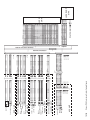
Wiring Diagrams
10-295
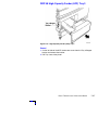
Phaser 7700 Finisher
11-313
Finisher Overview 11-314
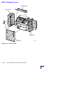
General Information ............................................................................................ 11-315
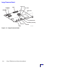
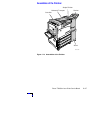
Assemblies of the Finisher .................................................................................. 11-317
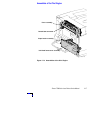
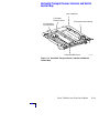
Internal Assemblies of the Finisher ..................................................................... 11-318
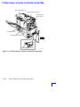
Horizontal Transport Sensor, Interlock, and Switch Locator Map ...................... 11-319
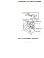
Finisher Sensor, Interlock, and Switch Locator Map ......................................... 11-320
Finisher Sensor, Interlock, and Switch Locator Map .......................................... 11-321
Removal and Replacement Procedures
11-323
Horizontal Transport Assembly ............................................................ 11-324
Horizontal Transport Top Open, Front, and Rear Cover 11-325
Horizontal Transport Entrance Upper Cover Assembly ......................... 11-326
Horizontal Transport Belts .................................................................... 11-327
xviii
Phaser 7700 Color Laser Printer Service Manual
Horizontal Transport Entrance Sensor and Top Tray Full Sensor ..........11-328
Gate-In Solenoid Assembly ...................................................................11-329
Finisher Covers .....................................................................................11-330
Stack Height-Sensor Assembly .............................................................11-332
Stacker Paper-Sensor Assembly ...........................................................11-333
Set Clamp Clutch and Gear ...................................................................11-334
Eject Roll Assembly ..............................................................................11-335
Finisher Control Board, Bracket, and Shield .........................................11-336
Stacker Motor Assembly .......................................................................11-338
Paddle Shaft .........................................................................................11-339
Paper Transport Motor (Motor Assembly Main) ...................................11-340
Cam Bracket Assembly .........................................................................11-341
Staple Unit Assembly and Motor ..........................................................11-342
Compiler Tray .......................................................................................11-344
Finisher FRU Parts List
11-345
Finisher Wiring Diagrams
12-371
Phaser 7700 Color Laser Printer Service Manual
xix
xx
Phaser 7700 Color Laser Printer Service Manual
List of Tables
Table 1-1 CRC Life .................................................................................................. 1-5
Table 1-2 Front Panel Key Descriptions ................................................................ 1-21
Table 1-3 Front Panel Shortcuts............................................................................ 1-22
Table 1-4 Rear Panel DIP Switch Settings............................................................. 1-23
Table 1-5 Physical Dimensions of the Printer ....................................................... 1-24
Table 1-6 Physical Dimensions of Lower Tray Feeder ........................................... 1-24
Table 1-7 Functional Specifications....................................................................... 1-25
Table 1-8 Electrical Specifications......................................................................... 1-25
Table 1-9 Environmental Specifications ................................................................ 1-26
Table 1-10 Specialty Paper.................................................................................... 1-28
Table 1-11 Print Area ............................................................................................ 1-28
Table 2-1 POST Diagnostics Test Descriptions ..................................................... 2-34
Table 2-2 Service Diagnostics Test Menu Functions ............................................. 2-36
Table 8-1 Accumulator Belt FRUs List ................................................................. 8-236
Table 8-2 Left-Hand Door FRUs List ................................................................... 8-238
Table 8-3 Media Trays FRUs List ....................................................................... 8-239
Table 8-4 Duplex Unit FRUs List ......................................................................... 8-240
Table 8-5 Cover FRUs List................................................................................... 8-241
Table 8-6 Cover FRUs (cont’d.) List .................................................................... 8-242
Table 8-7 Covers FRUs List (cont’d.) .................................................................. 8-244
Table 8-8 Switch and Sensor FRUs List .............................................................. 8-246
Table 8-9 Switch and Sensor FRUs List (cont’d.)................................................ 8-248
Table 8-10 Circuit Board FRUs List ..................................................................... 8-250
Table 8-11 Power Supplies FRUs List ................................................................. 8-252
Table 8-12 Power Supplies FRUs List (cont’d.)................................................... 8-254
Table 8-13 Motors / Drivers FRUs List................................................................ 8-256
Table 8-14 Electrophotographic Components FRUs List ..................................... 8-258
Table 8-15 Electrophotographic Components FRUs List (cont’d.) ...................... 8-260
Table 8-16 Multi-Purpose Tray (MPT) FRUs List ................................................ 8-262
Table 8-17 Paper Feed FRUs List ........................................................................ 8-264
Table 8-18 Paper Feed FRUs List (cont’d.)......................................................... 8-266
Table 8-19 Fans FRUs List .................................................................................. 8-267
Table 8-20 Lift Components FRUs List................................................................ 8-269
Table 8-21 Wiring FRUs List ............................................................................... 8-271
Table 8-22 Auxiliary Feeders FRUs List............................................................... 8-273
Table 8-23 Lower Tray Deck (LTD) FRUs List ..................................................... 8-275
Table 8-24 Lower Tray Deck (LTD) FRUs List (cont’d.)....................................... 8-276
Table 8-25 High-Capacity Feeder FRUs List ........................................................ 8-277
Table 8-26 High-Capacity Feeder FRUs List (cont’d.).......................................... 8-278
Table 8-27 High-Capacity Feeder FRUs List (cont’d.).......................................... 8-279
Phaser 7700 Color Laser Printer Service Manual
xxi
Table 8-28 High-Capacity Feeder FRUs List (cont’d.) .......................................... 8-280
Table 8-29 High-Capacity Feeder FRUs (cont’d.) ................................................. 8-281
Table 8-30 Kits .................................................................................................... 8-282
Table 8-31 Manual Packs & Service Manual........................................................ 8-283
Table 8-32 Software ............................................................................................ 8-284
Table 8-33 Supplies............................................................................................. 8-284
Table 8-34 Accessories ....................................................................................... 8-285
Table 8-35 Recommended Tools List .................................................................. 8-285
Table 11-1 Finisher Specifications ..................................................................... 11-315
Table 11-2 Finisher Unit Main Assemblies FRUs List ........................................ 11-346
Table 11-3 Finisher Covers FRUs List................................................................ 11-347
Table 11-4 Finisher Stand FRUs List.................................................................. 11-349
Table 11-5 Gate Unit FRUs List.......................................................................... 11-351
Table 11-6 Horizontal Transport Assembly FRUs List ....................................... 11-353
Table 11-7 Horizontal Transport Assembly FRUs List (cont’d.) ......................... 11-355
Table 11-8 Top Cover and Eject Roll FRUs List ................................................. 11-357
Table 11-9 Paper Transport Assembly FRUs List .............................................. 11-359
Table 11-10 Paper Transport Assembly FRUs List (cont’d.) .............................. 11-361
Table 11-11 Staple Unit Assembly FRUs List..................................................... 11-363
Table 11-12 Compiler Tray Assembly FRUs List................................................ 11-365
Table 11-13 Stacker Elevator Assembly FRUs List ............................................ 11-367
Table 11-14 Exit Assembly FRUs List ................................................................ 11-369
Table 11-15 Electrical FRUs List ........................................................................ 11-370
xxii
Phaser 7700 Color Laser Printer Service Manual
List of Figures
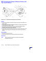
Figure 1-1 The Phaser 7700 Color Laser Printer (shown with the High-Capacity Feeder)
1-1
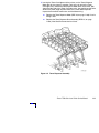
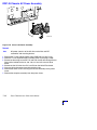
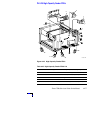
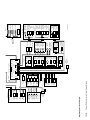
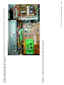
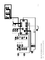
Figure 1-2 Engine Control Interface and Power Supply Boards ............................... 1-6
Figure 1-3 Power Supplies ...................................................................................... 1-7
Figure 1-4 Engine Control and Image Processor Boards ......................................... 1-8
Figure 1-5 Auxiliary Feeder Control Board ............................................................... 1-9
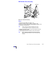
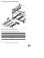
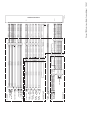
Figure 1-6 Print Engine Sensors and Switches ..................................................... 1-10
Figure 1-7 Print Engine Sensors and Switches (cont’d.) ....................................... 1-11
Figure 1-8 Auxiliary Feeder Sensors and Switches ................................................ 1-12
Figure 1-9 Auxiliary Feeder Actuators and Clutches .............................................. 1-13
Figure 1-10 Print Engine Solenoids, Actuators, and Clutches ............................... 1-14
Figure 1-11 Print Engine and Auxiliary Feeder Interlocks and Sensors ................. 1-15
Figure 1-12 Image Processor Board ..................................................................... 1-16
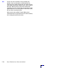
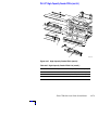
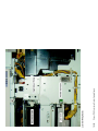
Figure 1-13 Assemblies of the Print Engine .......................................................... 1-17
Figure 1-14 Assemblies of the Print Engine (cont’d.) ............................................ 1-18
Figure 1-15 Assemblies of the Print Engine (cont’d.) ............................................ 1-19
Figure 1-16 Auxiliary Feeder Assemblies ............................................................... 1-20
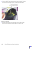
Figure 1-17 Front Panel ......................................................................................... 1-21
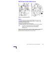
Figure 1-18 Printer Rear Connections ................................................................... 1-23
Figure 1-19 Printer Clearances .............................................................................. 1-24
Figure 2-1 Voltage Measurement Point Locations ................................................. 2-46
Fig 2-2 Fuser Connector Pin Locations ................................................................. 2-47
Figure 3-1 Circuit Diagram .................................................................................... 3-91
Figure 3-2 Toner Cartridge Gear ............................................................................ 3-97
Figure 3-3 Toner Cartridge .................................................................................... 3-98
Figure 3-4 Toner Dispense Assembly .................................................................... 3-99
Figure 3-5 Toner Port .......................................................................................... 3-100
Figure 3-6 Developer Housing ............................................................................. 3-103
Figure 4-1 Coarse RegiCon Initialization ............................................................. 4-124
Figure 4-2 Coarse and Fine Skew Adjustments ................................................... 4-125
Figure 4-3 In/Out Skew Adjustment .................................................................... 4-125
Figure 4-4 Center Skew Adjustment .................................................................... 4-126
Figure 4-5 RegiCon Flowchart ............................................................................. 4-133
Figure 4-6 Grid 1-Dot Pattern Orientation for A-size Paper ................................. 4-140
Figure 4-7 Grid 1-Dot pattern annotations .......................................................... 4-141
Figure 7-1 Rear Cover Assembly ......................................................................... 7-154
Figure 7-2 Right Side Cover Assembly ................................................................ 7-155
Figure 7-3 Top Cover Assembly .......................................................................... 7-156
Figure 7-4 Control Panel Assembly ..................................................................... 7-157
Figure 7-5 Top Rear Power Switch Cover and Left-Hand Rear Mid Cover ........... 7-158
Phaser 7700 Color Laser Printer Service Manual
xxiii
Figure 7-6 Left-Hand Lower Cover Assembly ...................................................... 7-160
Figure 7-7 Front Cover Assembly ........................................................................ 7-161
Figure 7-8 Fuser Front Cover ............................................................................... 7-162
Figure 7-9 Rear Shield ......................................................................................... 7-163
Figure 7-10 Rear Shield Bracket .......................................................................... 7-164
Figure 7-11 24 VDC Power Supply Shield ........................................................... 7-165
Figure 7-12 MPT Assembly ................................................................................. 7-166
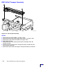
Figure 7-13 Multi-Purpose Tray Pick Rollers ....................................................... 7-167
Figure 7-14 Left-Hand Cover Assembly (Left-Hand Door) ................................... 7-168
Figure 7-15 Damper Teeth Alignment .................................................................. 7-169
Figure 7-16 Duplex Chute .................................................................................... 7-170
Figure 7-17 Duplex Unit Assembly ...................................................................... 7-171
Figure 7-18 Transfer Roller Assembly (2nd BTR) ................................................ 7-172
Figure 7-19 Inverter Transport Assembly ............................................................ 7-173
Figure 7-20 Fuser Unit ......................................................................................... 7-174
Figure 7-21 Registration Transport Assembly ..................................................... 7-175
Figure 7-22 Shutter Solenoid Assembly .............................................................. 7-176
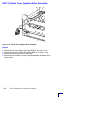
Figure 7-23 Tray 1 Feeder Assembly ................................................................... 7-177
Figure 7-24 Waste Cartridge, Waste Cartridge Cover and Waste Cartridge Sensor Holder
7-178
Figure 7-25 Print Cartridge Plate Cover (plastic) ................................................. 7-179
Figure 7-26 Dispense Assembly .......................................................................... 7-180
Figure 7-27 Print Cartridge Plate Assembly ......................................................... 7-182
Figure 7-28 Print Cartridge Plate Assembly (cont’d.) .......................................... 7-183
Figure 7-29 Developer Housing Assembly ........................................................... 7-185
Figure 7-30 Developer Housing Assembly Recharge ........................................... 7-186
Figure 7-31 Toner Dispense Motor Assembly ...................................................... 7-188
Figure 7-32 Steering Drive Assembly .................................................................. 7-189
Figure 7-33 Waste Toner Agitator Motor Assembly. ............................................ 7-190
Figure 7-34 Mark-On-Belt Sensor ........................................................................ 7-191
Figure 7-35 Exit Transport Assembly ................................................................... 7-192
Figure 7-36 Reconfigured Inverter ....................................................................... 7-193
Figure 7-37 Parts No Longer Installed ................................................................. 7-193
Figure 7-38 Interlock Actuator and Spacers ........................................................ 7-194
Figure 7-39 Fuser Fan Assembly ......................................................................... 7-195
Figure 7-40 Accumulator Belt Assembly .............................................................. 7-196
Figure 7-41 Belt Cleaner Assembly ...................................................................... 7-198
Figure 7-42 Waste Auger Assembly ..................................................................... 7-199
Figure 7-43 Laser Unit Assembly ......................................................................... 7-200
Figure 7-44 Laser Unit Label ............................................................................... 7-201
Figure 7-45 Image Processor Board Assembly. ................................................... 7-202
Figure 7-46 Internal Hard Drive ........................................................................... 7-203
Figure 7-47 Electrical Chassis Assembly ............................................................. 7-204
Figure 7-48 Engine Control Board ....................................................................... 7-206
Figure 7-49 Engine Control Interface Board ......................................................... 7-207
Figure 7-50 T1 and T3 High-voltage Power Supplies ........................................... 7-208
xxiv
Phaser 7700 Color Laser Printer Service Manual
Figure 7-51 3.3 VDC and 5 VDC Low-Voltage Power Supplies ............................ 7-210
Figure 7-52 LD Power Relay ............................................................................... 7-211
Figure 7-53 Low-voltage Power Supply, Fan and Bracket ................................... 7-212
Figure 7-54 T2 High-Voltage Power Supply ........................................................ 7-213
Figure 7-55 Chassis AC Power Assembly ............................................................ 7-214
Figure 7-56 Main Drive Assembly ....................................................................... 7-215
Figure 7-57 Accumulator Belt Drive Assembly .................................................... 7-217
Figure 7-58 Developer Drive Assembly ............................................................... 7-218
Figure 7-59 Print Cartridge Drive Assembly ........................................................ 7-219
Figure 7-60 Tray 1 Paper-Select Switches .......................................................... 7-220
Figure 7-61 Main Lever, Right-Hand and Left-Hand Jacks .................................. 7-221
Figure 7-62 Lift Pin Alignment ............................................................................ 7-223
Figure 7-63 Cover Screw Location ...................................................................... 7-223
Figure 7-64 Cover Removed ................................................................................ 7-224
Figure 7-65 Tension Spring Location .................................................................. 7-224
Figure 7-66 Front and Rear Gears Aligned .......................................................... 7-224
Figure 7-67 Auxiliary Feeder Covers .................................................................... 7-225
Figure 7-68 High-Capacity Feeder (HCF) Cover Assembly ................................... 7-226
Figure 7-69 High-Capacity Feeder (HCF) Tray 3 .................................................. 7-227
Figure 7-70 High-Capacity Feeder (HCF) Tray 4 and Paper Transport ................. 7-228
Figure 7-71 LTD Control or HCF Control Board ................................................... 7-229
Figure 7-72 Transport Motor Assembly .............................................................. 7-230
Figure 7-73 Paper-Select Switches ..................................................................... 7-231
Figure 7-74 Paper Feed Motor Assembly and Chute (LTA & HCF) ...................... 7-232
Figure 7-75 Bracket Assembly, Gear RH & Gear LH (HCF) .................................. 7-233
Figure 8-1 Accumulator Belt FRUs ........................................................................8-236
Figure 8-2 Left-Hand Door FRUs ......................................................................... 8-237
Figure 8-3 Media Trays FRUs .............................................................................. 8-239
Figure 8-4 Duplex Unit FRUs ............................................................................... 8-240
Figure 8-5 Cover FRUs ........................................................................................ 8-241
Figure 8-6 Cover FRUs (cont’d.) .......................................................................... 8-242
Figure 8-7 Cover FRUs (cont’d.) .......................................................................... 8-243
Figure 8-8 Switch and Sensor FRUs .................................................................... 8-245
Figure 8-9 Switch and Sensor FRUs (cont’d.) ..................................................... 8-247
Figure 8-10 Circuit Boards FRUs ......................................................................... 8-249
Figure 8-11 Power Supplies FRUs ....................................................................... 8-251
Figure 8-12 Power Supplies FRUs (cont’d.) ........................................................ 8-253
Figure 8-13 Motors/Drivers FRUs ....................................................................... 8-255
Figure 8-14 Electrophotographic Components FRUs .......................................... 8-257
Figure 8-15 Electrophotographic Components FRUs (cont’d.) ............................ 8-259
Figure 8-16 Multi-Purpose Tray FRUs ................................................................. 8-261
Figure 8-17 Paper Feed FRUs .............................................................................. 8-263
Figure 8-18 Paper feed FRUs (cont’d.) ................................................................ 8-265
Figure 8-19 Fans FRUs ........................................................................................ 8-267
Figure 8-20 Lift Components FRUs ..................................................................... 8-268
Figure 8-21 Wiring FRUs ..................................................................................... 8-270
Phaser 7700 Color Laser Printer Service Manual
xxv
Figure 8-22 Auxiliary Feeder FRUs ....................................................................... 8-272
Figure 8-23 Lower Tray Deck (LTD) FRUs ........................................................... 8-274
Figure 8-24 Lower Tray Deck (LTD) FRUs (cont’d.) ............................................. 8-276
Figure 8-25 High-Capacity Feeder FRUs .............................................................. 8-277
Figure 8-26 High-Capacity Feeder FRUs (cont’d.) ................................................ 8-278
Figure 8-27 High-Capacity Feeder FRUs (cont’d.) ................................................ 8-279
Figure 8-28 High-Capacity Feeder FRUs (cont’d.) ................................................ 8-280
Figure 8-29 High-Capacity Feeder FRUs (cont’d.) ................................................ 8-281
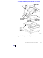
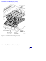
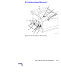
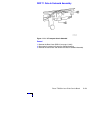
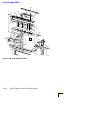
Figure 11-1 Phaser 7700 Color Laser Printer with the Finisher Option .............. 11-313
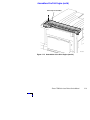
Figure 11-2 Dimensions of the Finisher ............................................................. 11-315
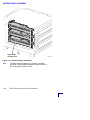
Figure 11-3 Assemblies of the Finisher .............................................................. 11-317
Figure 11-4 Internal Assemblies of the Finisher ................................................. 11-318
Figure 11-5 Horizontal Transport Sensor, Interlock and Switch Locator Map ... 11-319
Figure 11-6 Finisher Sensor, Interlock, and Switch Locator Map ...................... 11-320
Figure 11-7 Finisher Sensor, Interlock, and Switch Locator .............................. 11-321
Figure 11-8 Horizontal Transport Assembly ...................................................... 11-324
Figure 11-9 H-Transport Top Open, Front and Rear Covers .............................. 11-325
Figure 11-10 Horizontal Transport Entrance Upper Cover ................................. 11-326
Figure 11-11 Horizontal Transport Belts ............................................................ 11-327
Figure 11-12 H-Tra Entrance and Top Tray Full Sensor ..................................... 11-328
Figure 11-13 H-Transport Gate-In Solenoid ....................................................... 11-329
Figure 11-14 Finisher Covers ............................................................................. 11-330
Figure 11-15 Stack Height-Sensor Assembly .................................................... 11-332
Figure 11-16 Stacker Paper-Sensor Assembly .................................................. 11-333
Figure 11-17 Set Clamp Clutch and Gear ........................................................... 11-334
Figure 11-18 Eject Roll ...................................................................................... 11-335
Figure 11-19 Finisher Control Board, Bracket, and Shield ................................. 11-336
Figure 11-20 Stacker Motor Assembly .............................................................. 11-338
Figure 11-21 Paddle Shaft ................................................................................. 11-339
Figure 11-22 Paper Transport Motor ................................................................. 11-340
Figure 11-23 Cam Bracket Assembly ................................................................. 11-341
Figure 11-24 Staple Unit Assembly ................................................................... 11-342
Figure 11-25 Compiler Tray ............................................................................... 11-344
Figure 11-26 Finisher Unit Main Assemblies FRUs ............................................ 11-345
Figure 11-27 Finisher Covers FRUs ................................................................... 11-347
Figure 11-28 Finisher Stand FRUs ..................................................................... 11-348
Figure 11-29 Gate Unit FRUs ............................................................................. 11-350
Figure 11-30 Horizontal Transport Assembly FRUs ........................................... 11-352
Figure 11-31 Horizontal Transport Assembly FRUs (cont’d.) ............................ 11-354
Figure 11-32 Top Cover and Eject Roll FRUs ..................................................... 11-356
Figure 11-33 Paper Transport Assembly FRUs .................................................. 11-358
Figure 11-34 Paper Transport Assembly FRUs (cont’d.) ................................... 11-360
Figure 11-35 Staple Unit Assembly FRUs .......................................................... 11-362
Figure 11-36 Compiler Tray Assembly FRUs ..................................................... 11-364
Figure 11-37 Stacker Elevator Assembly FRUs .................................................. 11-366
Figure 11-38 Exit Assembly FRUs ..................................................................... 11-368
xxvi
Phaser 7700 Color Laser Printer Service Manual
Figure 11-39 Electrical FRUs ............................................................................. 11-370
Figure 12-1 Block diagram of the Finisher .......................................................... 12-372
Figure 12-2 Wiring diagram of the Finisher ....................................................... 12-373
Phaser 7700 Color Laser Printer Service Manual
xxvii
xxviii
Phaser 7700 Color Laser Printer Service Manual
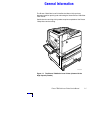
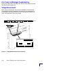
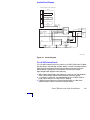
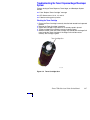
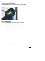
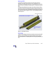
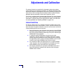
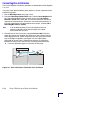
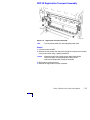
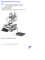
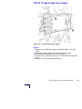
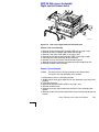
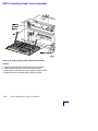
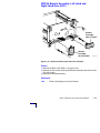
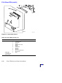
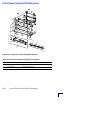
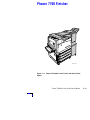
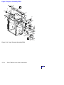
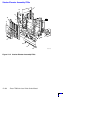
General Information
The Phaser 7700 Color Laser Printer Service Manual is the primary
document used for repairing and maintaining the Xerox Phaser 7700 Color
Laser Printer.
Certification for servicing of this product requires completion of the Phaser
7700 printer service training.
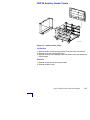
S7700-433
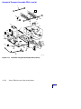
Figure 1-1 The Phaser 7700 Color Laser Printer (shown with the
High-Capacity Feeder)
Phaser 7700 Color Laser Printer Service Manual
1-1
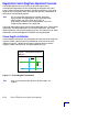
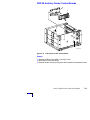
Phaser 7700 Printer Overview
The Phaser 7700 Color Printer combines a single-pass, tandem-design, color
laser, continuous-tone print engine with an image processor supporting
Adobe’s PostScript 3 description language. The image processor features a
bi-directional parallel interface, a USB port, and a 100baseT Ethernet port for
host communication. The PCL5C printer language is also supported.
The 7700 printer prints at a standard resolution of 600 x 1200 dots-per-inch
with bi-level dots and at a high resolution of 600 x 600 dots-per-inch with
variable dot sizing. The printer can print up to 22 A/A4-size pages per minute.
All printers feature an Internal Hard Drive for font storage, storing print files,
print collation support, and a “check print before proceeding” mode. The hard
drive also contains printer documentation accessible via a web browser. The
printer contains 136 standard, built-in fonts.
All printers feature a built-in duplex unit, which supports printing on both sides
of a sheet of paper.
The printer features a built-in, 100-sheet multi-purpose tray from which
specialty media, card stock, larger format paper, and envelopes can be fed.
The printer also supports manual feeding using the Multi-Purpose Tray.
The Lower Tray Assembly is available with three additional 500-sheet
universal media trays. A High-Capacity Feeder is also available which
features two high-capacity A/A4-size trays and one 500-sheet universal tray.
An optional 1000-sheet, high-capacity stapler/stacker is available with the
Lower Tray Deck or High-Capacity Feeder. The printer is marketed in three
versions:
■
The Phaser 7700 DN Printer comes standard with 128 Mbytes of
RAM.
■
The Phaser 7700 GX Printer features 256 MB of RAM, a three-tray
Lower Tray Deck, and PhaserMatch 7700 ICC Color Matching
Software.
■
The Phaser 7700 DX Printer features 256 MB of RAM, a
High-Capacity Feeder and Finisher.
RAM memory in the printers can be supplemented with one additional 64-,
128- or 256-Mbyte RAM SODIMMs; the maximum usable capacity is 512 MB
in the printer’s two memory slots
After being idle for the selected amount of time the printer switches into its
ENERGY STARTM mode where it consumes less than 45 watts of power. It
“awakens” upon receiving data at any of its ports.
1-2
Phaser 7700 Color Laser Printer Service Manual
Proof Jobs
A proof job is a specific case of a multiple-copy job. With a proof job, the
customer assigns a password and copy account at the client workstation
before printing. The first set of prints are printed immediately. The original
number of requested sets are printed after the customer enters the matching
password on the printer’s control panel. The customer has the option of
printing the original number of requested sets or deleting the job. Since more
than one job may be associated with the same password, the customer can
print all the jobs, delete all the jobs, or select or delete individual jobs. A proof
job that has not been printed is retained on the built in Internal Hard Drive
through power cycles.
Secure Jobs
Secure printing allows the customer to defer printing of a job until a matching
password is entered from the control panel. The customer assigns the
password at the client workstation before printing. The job is stored, and
printing is delayed until the password is entered on the printer’s control panel.
Since more than one job can have the same password, all secure jobs with
the same password are printed. A secure job that has not been printed or
released is retained on the Internal Hard Drive through power cycles.
Saved Jobs
Saved print allows the user to save print jobs to the internal hard drive of the
printer. The print job is not deleted after printing, it is stored on the hard drive
for print on demand. This function requires the internal hard drive.
Note
For additional service information, refer to the Service
CD-ROM or the Xerox Service Website:
http://cpidserv.opbu.xerox.com.
Phaser 7700 Color Laser Printer Service Manual
1-3
Printer RAM and Printer Capabilities
The printer features two slots which accept 64, 128 and 256 Mbytes of
SDRAM. All combinations are allowed for configurations of 128, 192, 256,
320, 384, and 512 Mbytes.
■
144 pin SODIMM
■
Serial presence detect
■
3.3 volt
■
100 MHz PC100 or 133 MHz PC133
The Startup Page and the Configuration Page list the amount of RAM
installed in the printer.
If memory does not meet the above specifications it will be ignored by the
printer.
With more memory the printer gains the capabilities of printing without having
to use image compression (which trades less installed RAM for longer image
processing time) and dual frame buffers for printing one image while
processing a second image (which gives greater printing throughput).
The printer features two slots each which can contain a 64-, 128-, or
256-Mbyte SDRAM. Any slot may be used for any size memory module.
SDRAM memory totalling beyond 512 Mbytes will be ignored.
For acceptable memory, see “Supplies and Accessories” on page 8-284.
1-4
Phaser 7700 Color Laser Printer Service Manual
CRC Life Counter Behavior
Internal counters track Customer-Replaceable Consumables (CRC) life usage
and store the values in NVRAM. The Image Processor Board monitors these
counters in order to display the near end-of-life and end-of-use messages.
Table 1-1 CRC Life
Accessory
Shelf Life from
Manufacturer
Print Cartridge
15 Months
24k color mode (K in B&W mode)
31.2k B&W mode on CMY units
Toner Cartridge
Black
Extended
Standard
24 Months
24 Months
12k at 5% coverage
5k at 5% coverage
Toner Cartridge
C, M, Y
Extended
Standard
24 Months
24 Months
10k at 5% coverage
4k at 5% coverage
2nd Transfer Roller
Kit
24 Months
100k, less w/duplex printing
Fuser Assembly
24 Months
60K Letter/A4 pgs, 24 lb. paper
Accumulator Belt
24 Months
300K
Accumulator Belt
Cleaner
24 Months
100k
Waste Toner
Cartridge
24 Months
6k, less with media pick jams
Phaser 7700 Color Laser Printer Service Manual
1-5
Engine Control Interface and Power Supply Boards
Engine Control Interface Board
High Voltage Power Supply/ T1 Board
High Voltage Power Supply/ T3 Board
High Voltage Power Supply/ T2 Board
GFI
AC Drive Board
Noise Filter Board
S7700-317
Figure 1-2 Engine Control Interface and Power Supply Boards
1-6
Phaser 7700 Color Laser Printer Service Manual
Power Supplies
24 V Low voltage
power supply
24 V Low voltage
power supply fan
AC Power Chassis
3.3 V Low voltage
power supply
5 V Low voltage
power supply
S7700-261
Figure 1-3 Power Supplies
Phaser 7700 Color Laser Printer Service Manual
1-7
Engine Control and Image Processor Boards
Image Processor Board
Engine Control Board
S7700-381
Figure 1-4 Engine Control and Image Processor Boards
1-8
Phaser 7700 Color Laser Printer Service Manual
Auxiliary Feeder Control Board
LTD Board (3T)
HCF Board (TT)
S7700-385
Figure 1-5 Auxiliary Feeder Control Board
Phaser 7700 Color Laser Printer Service Manual
1-9
Print Engine Sensors and Switches
Transfer Roller Sensor
Tray 1 Take-Away Sensor
Transparency Sensor
Registration Sensor
Paper On Belt Sensor
MPT No Paper Sensor
Tray 1 No Paper Sensor/Level Sensor
MPT Paper Size Sensor
Figure 1-6 Print Engine Sensors and Switches
1-10
Phaser 7700 Color Laser Printer Service Manual
S7700-287
Print Engine Sensors and Switches (cont’d.)
Environment
Sensor
Automatic Density
Control Sensor
Accumulator Belt
Home Sensor
Duplex
Wait Sensor
Accumulator Belt
Edge Sensor
Automatic Toner
Correction Sensor
K, C, M, Y
Tray 1 Paper
Size Sensor
Mark On
Belt Sensor
Waste Cartridge
Full Sensor
S7700-288
Figure 1-7 Print Engine Sensors and Switches (cont’d.)
Phaser 7700 Color Laser Printer Service Manual
1-11
Auxiliary Feeder Sensors and Switches
Paper-Size Switch Assembly -Tray 2
Tray 4 Take-Away Sensor
-Tray 3
Tray 3 Take-Away Sensor
-Tray 4
LTD
2
3
4
Take-Away Sensor
No-Paper Sensor/Level Sensor
Tray 2
Tray 3
Tray 4
Paper-Size Switch Assembly
-Tray 2
Paper-Size Switch Assembly
-Tray 3
-Tray 4
2
HCF
4
3
Tray 3 Take-Away Sensor
Tray 4 Take-Away Sensor
Figure 1-8 Auxiliary Feeder Sensors and Switches
1-12
Phaser 7700 Color Laser Printer Service Manual
S7700-316
Auxiliary Feeder Actuators and Clutches
Left hand cover
interlock switch
actuator
Paper feed
sensor actuator
tray 3
LTD
Paper detect
sensor actuator
tray 2
tray 3
tray 4
One way
clutch
tray 2
tray 3
tray 4
Friction
clutch
tray2
tray 3
tray 4
Paper feed
sensor actuator
tray 4
HCF
Left hand cover
interlock switch
actuator
Friction
clutch
tray 2
Paper detect
sensor actuator
tray 2
tray 3
Paper size
switch
actuator
tray 4
One way
clutch
tray4
One way
clutch
tray 2
tray 3
Paper detect
sensor actuator
tray 4
Friction
Paper size
clutch
switch
tray 3
actuator
tray 3
Friction
clutch
tray 4
S7700-388
Figure 1-9 Auxiliary Feeder Actuators and Clutches
Phaser 7700 Color Laser Printer Service Manual
1-13
Print Engine Solenoids, Actuators, and Clutches
CW Duplex
clutch
Exit tray
full sensor
actuator
CCW Duplex
clutch
Registration
clutch
Feed clutch
One way
clutch
Friction
clutch
Paper detect
sensor actuator
(tray 1)
One way
clutch
Paper detect
sensor actuator
(MPT)
S7700-387
Figure 1-10 Print Engine Solenoids, Actuators, and Clutches
1-14
Phaser 7700 Color Laser Printer Service Manual
Print Engine and Auxiliary Feeder Interlocks and Sensors
Right-hand cover
interlock switch
Left-hand
cover interlock
switch
Main power
switch
Fuser-exit
switch
Front-coverinterlock
switch
Duplex cover switch
Left hand lower
cover sensor
Transfer-rollerposition sensor
(behind transfer
roller)
Waste-cartridgeinterlock switch
Auxiliaryfeederleft-hand
cover-interlock
switch
S7700-390
Figure 1-11 Print Engine and Auxiliary Feeder Interlocks and
Sensors
Phaser 7700 Color Laser Printer Service Manual
1-15
Image Processor Board
Processor
SODIMM2
J500
Health LED
SODIMM1
Hard Drive
DIP Switches
NVRAM (socketed)
Ethernet
Parallel
USB
Figure 1-12 Image Processor Board
1-16
Phaser 7700 Color Laser Printer Service Manual
S7700-258
Assemblies of the Print Engine
Fuser assembly
Detack Saw connector
Paper feeder assembly
Left-Hand lower cover assembly
S7700-266
Figure 1-13 Assemblies of the Print Engine
Phaser 7700 Color Laser Printer Service Manual
1-17
Assemblies of the Print Engine (cont’d.)
Toner cartridge (4x)
K
C
M
Y
Developer
housing
assemblies (4x)
Print cartridge plate
Waste cartridge
sensor holder
Dispenser
assembly (4x)
Figure 1-14 Assemblies of the Print Engine (cont’d.)
1-18
Phaser 7700 Color Laser Printer Service Manual
S7700-312
Assemblies of the Print Engine (cont’d.)
Exit transport assembly
S7700-386
Figure 1-15 Assemblies of the Print Engine (cont’d.)
Phaser 7700 Color Laser Printer Service Manual
1-19
Auxiliary Feeder Assemblies
Paper feeder
assembly (3X)
Figure 1-16 Auxiliary Feeder Assemblies
Note
1-20
The High-Capacity Feeder has a Tandem Tray design
with three Paper Feeder Assemblies, two on the left and
one on the right side of the Printer.
Phaser 7700 Color Laser Printer Service Manual
S7700-368
Front Panel Description
The Front Panel consists of one tricolor LED, a display window and six
functional keys. These keys navigate the menu system, perform functions and
select modes of operation for the printer.
LED indicators
■
Green = Ready to print/printing
■
Flashing Green = Receiving or Processing Data
■
Yellow = Warning
■
Red = Fatal Error
3
5
Phaser 7700
OK
1
2
4
6
7
8
S7700-437
Figure 1-17 Front Panel
Table 1-2 Front Panel Key Descriptions
1
LED (Power/Status)
5
Up Arrow Button - moves up the menu system
2
Graphic front panel display
6
Down Arrow Button - moves down the menu
system
3
Cancel Button
7
OK (select) Button
4
Back Button
8
Information Button - for additional explanation or
help
Phaser 7700 Color Laser Printer Service Manual
1-21
Front Panel Shortcuts
You can perform several service tasks by using the options shown in the table.
Table 1-3 Front Panel Shortcuts
Mode
Press this selection at Power On
Skip execution of POST diagnostics
OK
Print service diagnostics map
INFO
Reset PostScript NVRAM
BACK+OK
Password Bypass
UP+DOWN
Enter Service Diagnostics
BACK+INFO
1-22
Phaser 7700 Color Laser Printer Service Manual
Rear Panel
Connectors
The rear panel of the printer features the host interface connectors and DIP
Switches:
■
USB port
■
Twisted Pair 10/100T Ethernet connector
■
Bi-directional parallel (high-density connector)
■
DIP Switches.
The following figure illustrates the rear connections panel of the printer.
USB
Parallel
Ethernet
DIP Switches
S7700-416
Figure 1-18 Printer Rear Connections
Table 1-4 Rear Panel DIP Switch Settings
Function
Switch 1
Switch 2
Switch 3
Switch 4
Normal (Customer) operating
mode
UP
UP*
UP*
UP
Service mode
UP
DOWN
UP
UP
Reset printer
UP*
UP*
UP*
DOWN
then UP**
Disaster Recovery mode
(engineering use only)
DOWN
UP
DOWN
UP
Development mode (engineering
use only
DOWN
DOWN
DOWN*
UP
* Recommended DIP switch position
** If DIP switch 4 is left in the down position, the printer will not turn Off.
Phaser 7700 Color Laser Printer Service Manual
1-23
Printer Specifications
Physical Dimensions and Clearances
Table 1-5 Physical Dimensions of the Printer
Dimension
Value
Height
493 mm (19.4 in.) Print Engine
857 mm (48. in.) with lower tray deck
Width
644 mm (25.4 in.)
Depth
682 mm (26.9 in.)
Weight
82 kg (180 lbs.) with consumables installed
122 kg (267 lbs.) with lower tray (high-capacity) feeder
Table 1-6 Physical Dimensions of Lower Tray Feeder
Dimension
Value
Height
41.4 cm (16.3 in.)
Width
56 cm (22 in.)
Depth
56 cm (22 in.)
Weight
23.5 kg (52 lbs.)
5.0 cm
(1.96 in.)
10.0 cm
(4.0 in.)
36.8 cm
(14.5 in.)
160.4 cm
(63.1 in.)
42.5 cm
(16.7 in.)
106.1 cm
(41.8 in.)
S7700-417
Figure 1-19 Printer Clearances
1-24
Phaser 7700 Color Laser Printer Service Manual
Table 1-7 Functional Specifications
Characteristic
Specification
Printing Process
The Printer uses laser print heads with an electrophotographic
four-color (CMYK) tandem architecture and intermediate transfer
printing process.
Color Medium
Four toner cartridges each containing one of four colors: CMYK
Addressability
600 x 600 x 1-bit dpi (OHP)
1200 x 600 x 1-bit dpi (standard)
600 x 600 x 3-bit+1-level dpi (photo)
Print Speed
Normal
Letter/A4 LEF (Long-Edge Feed): 22 pages per minute
Tabloid/A3 SEF (Short-Edge Feed): 11 pages per minute
Legal SEF: 13 pages per minute
Duplex
Letter/A4 LEF: 18 pages per minute
Tabloid/A3 SEF: 8 pages per minute
Legal SEF: 9 pages per minute
Minimum Margins
5 mm (0.2 in.) on all sides
Tray Capacities
Main Tray:
Standard paper: 500 sheets
Transparency: 100 sheets
Lower feeder deck:
Standard paper: 1,500 sheets (3 x 500)
Multi-purpose tray:
Standard paper/Letterhead: 100 sheets
High-capacity feeder
Standard paper: 2500
(1) 500 sheets
(2) 867 sheets
(3) 1133 sheets
Table 1-8 Electrical Specifications
Characteristic
Specification
Primary Line Voltage
115/127 VAC 10A (+/- 10%)
200/240 VAC 5A (+/- 10%)
Line Frequency Range
100-127 VAC, 50/60 Hz
220-240 VAC, 50/60 Hz
Power Consumption
Energy Star: 45 watts
Standby: 130 watts
Ready: 220 watts
Continuous
Printing: 220 to 600 watts average
Peak (warming up) to 1100 watts
Phaser 7700 Color Laser Printer Service Manual
1-25
Table 1-9 Environmental Specifications
Characteristic
Specification
Temperature:
Operating
Storage
10 to 32o C
-20 to 50o C
Humidly:
Operating
Storage
10 to 85% relative humidity
30 to 85% relative humidity
Altitude
0 to 2500 m (8000 ft.) at 25o C
Acoustic Noise
Idle:
Printing:
38.3 db
54.8 db with impulse noise of 63.3 db
1-26
Phaser 7700 Color Laser Printer Service Manual
Supported Paper Weights, Page Sizes and Print Area
Supported Paper Sizes
The table identifies the paper weights that can be placed in each tray: Laser
Paper with the following weights: 60-90 g/m2 (16-24 lb. bond, 40-60 lb. book);
Heavy Laser Paper with the following weights: 91-105 g/m2 (25-28 lb. bond,
61-71 lb. book); Thin Cover/ Index with the following weights: 106-169 g/m2
(50-60 lb. cover, 65-90 lb. index, 32-40 lb. bond) and Thick Cover/Index with
the following weights: 170-220 g/m2 (65-80 lb. cover, 100-110 lb. Index).
Paper Size
Statement (5.5 x 8.5 in.)
Universal
Tray 1
Universal
Trays
2- 4a
•
•
MultiPurpose
Tray
•
•
Executive (7.25 x 10.5 in.)
•
8 x 10 in.
High-capa
city Trays
(3-4)
•
•
•
UK Foolscap (8 x 13 in.)
A/Letter (8.5 x 11 in.)
•
•
•
US Folio (8.5 x 13 in.)
•
•
•
Legal (8.5 x 14 in.)
•
•
•
B/Tabloid (11 x 17 in.)
•
•
•
Tabloid Extra (12 x 18 in.)
•
A6 (105 x 148 mm)
•
A5 (148 x 210 mm)
•
•
•
A4 (210 x 297 mm)
•
•
•
A3 (297 x 420 mm)
•
•
•
SP Folio (215 x 315 mm)
•
Oficio (215 x 340 mm)
•
B6 JIS (128 x 182 mm)
•
B5 JIS (182 x 257 mm)
•
•
•
B4 JIS (257 x 364 mm)
•
•
•
RA3 (305 x 430 mm)
•
SRA3 (320 x 450 mm)
•
•
•
•
a. Thin Cover/Index paper cannot be used in Trays 2-4.
Phaser 7700 Color Laser Printer Service Manual
1-27
Table 1-10 Specialty Paper
Paper Type and Size
Tray 1
Phaser 7700 Premium
Transparency
Trays
2- 4
MultiPurpose
Tray
•
HighCapacity
Feeder
•
Labels
•
Paper Envelopes (all sizes)
•
Table 1-11 Print Area
Paper
Page Size
Image Area
Margin
Top /
Bottom
Sides
Statement
5.5 x 8.5 in.
5.1 x 8.1 in.
.2 in.
.2 in.
Executive
7.25 x 10.5 in.
6.85 x 10.1 in.
.2 in.
.2 in.
8 x 10 in.
8 x 10 in.
7.6 x 9.6 in.
.2 in.
.2 in.
UK Foolscap
8 x 13 in.
7.6 x 12.6 in.
.2 in.
.2 in.
Letter
8.5 x 11 in.
215.9 x 279.4 mm
8.1 x 10.6 in.
205.9 x 269.4 m
m
.2 in.
5 mm
.2 in.
5 mm
US Folio
8.5 x 13 in.
8.1 x 12.6 in.
.2 in.
.2 in.
Legal
8.5 x 14 in.
216 x 356 mm
8.1 x 13.6 in.
.2 in.
.2 in.
Tabloid
11 x 17 in.
279 x 432 mm
10.4 x 16.4 in.
269 x 432 mm
.2 in.
5 mm
.2 in.
5 mm
Tabloid Extra
12 x 18 in.
11.6 x 17.6 in.
.2 in.
.2 in.
A6
105 x 148 mm
95 x138 mm
5 mm
5 mm
A5
148 x 210 mm
5.83 x 8.27 in.
138 x 200 mm
5.43 x 7.87 in.
5 mm
.2 in.
5 mm
.2 in.
A4
210 x 297 mm
8.3 x 11.7 in.
200 x 287 mm
7.9 x 11.3 in.
5 mm
.2 in.
5 mm
.2 in.
A3
297 x 420 mm
11.7 x 16.5 in.
287 x 410 mm
11.3 x 16.1 in.
5 mm
.2 in.
5 mm
.2 in.
SP Folio
215 x 315 mm
205 x 305 mm
5 mm
5 mm
Oficio
215 x 340 mm
205 x 330 mm
5 mm
5 mm
B6 JIS
128 x 182 mm
118 x 172 mm
5 mm
5 mm
B5 JIS
182 x 257 mm
172 x 247 mm
5 mm
5 mm
B4 JIS
257 x 364 mm
247 x 354 mm
5 mm
5 mm
1-28
Phaser 7700 Color Laser Printer Service Manual
Table 1-11 Print Area (cont'd.)
Paper
Page Size
RA3
305 x 430 mm
SRA3a
Image Area
Margin
Top /
Bottom
Sides
297 x 420 mm
5 mm
4 mm
320 x 450 mm
303 x 432 mm
9 mm
8.5 mm
Official #10
Envelope
4.13 x 9.5 in.
105 x 241 mm
3.73 x 9.1 in.
95 x 231 mm
.2 in.
5 mm
.2 in.
5 mm
#9 1/2 Booklet
9 x 12 in.
8.6 x 11.6 in.
.2 in.
.2 in.
DL Envelope
110 x 220 mm
100 x 210 mm
5 mm
5 mm
B6 Envelope
125 x 176 mm
115 x 166 mm
5 mm
5 mm
B5 Envelope
176 x 250 mm
166 x 240 mm
5 mm
5 mm
B4 Envelope
250 x 353 mm
240 x 343 mm
5 mm
5 mm
C6 Envelope
114 x 162 mm
104 x 152 mm
5 mm
5 mm
C5 Envelope
162 x 229 mm
152 x 219 mm
5 mm
5 mm
C4 Envelope
229 x 324 mm
9.02 x 12.8 in.
219 x 314 mm
5 mm
.2 in.
5 mm
.2 in.
a. SRA3 paper size and A3 full-bleed imageable area are supported through the
Multi-Purpose Tray (MPT). print-quality outside the imageable area is not guaranteed.
Phaser 7700 Color Laser Printer Service Manual
1-29
1-30
Phaser 7700 Color Laser Printer Service Manual
Diagnostics, Error Codes and
Messages
Error Messages
The Control Panel displays error codes when it encounters certain system
failures or anomalies otherwise undetected by the user. These error codes
are discussed in this section. When an error code first occurs, cycle the
printer power On to see if the error recurs.
■
For Printer Performance problems, see Troubleshooting on
page 3-87.
■
For Print Image Quality problems, see Print Image Quality
Problems on page 3-108.
Troubleshooting Error Codes
Chain / Link
Definitions: A chain-link number is always represented as a pair, with the
chain first and the link second.
Chain: A three digit identifier of a major attribute, counter or assembly.
Link: A three digit identifier of a specific component within the major attribute,
counter or assembly.
Where do they come from?
The chain-link encoding structure is used to identify or address a specific
component within the printer. The chain points to a high level attribute or
counter or component assembly, and the link points to a specific item in that
assembly.
Why are they here?
The printer uses chain-links to enumerate printer faults, and electronically
address printer components or operations. Most fatal faults are identified by a
number between 10 and 125, but a few faults are identified by the chain-link
identifier.
Phaser 7700 Color Laser Printer Service Manual
2-31
System Boot Sequence
1. The main power switch is turned On. The health LED turns On
immediately.
2. The boot loader checks for RAM present and functional - if not, it posts a
very large “RAM ERROR” on the Front Panel and blinks the LED 1/2
second On/Off continuously.
3. The boot Loader then runs POST diagnostics.
4. POST turns Off the health LED.
5. Post checks the Front Panel.
6. If keys have been pushed, the front panel displays “Processing Input.”
7. The front panel LED cycles; Green, Yellow, Red, Off.
8. The graphic panel turns On, the LED turns Green and the POST tests are
run.
Power On Self Test (POST)
The following tests are performed when the printer is powered On, after the
boot loader runs and before the operating system is loaded and initialized.
Post diagnostics are intended to provide a quick means of isolating a defective
subsystem associated with the Image processor board and SDRAM, POST
Diagnostics Test Descriptions on page 2-34. POST returns control of the boot
loader and the operating system is loaded. The operating system then loads
the imaging processing software. If Post detected any soft errors a message
is printed in a red box on the start page. If POST detects any hard errors both
the front panel and health Led blink the error code pattern, see LED Blink
Patterns on page 2-33.
2-32
Phaser 7700 Color Laser Printer Service Manual
POST Faults
There are two kinds of faults: Soft and Hard.
A soft fault is any fault that is discovered by POST but does not prevent the
operating system from initializing and becoming available as a tool for
troubleshooting. These POST faults do not stop execution and are reported
on the StartPage, in a red box, after the system is running.
A hard fault is any fault discovered by POST that prevents the operating
system from initializing successfully. A hard fault prevents the system from
further execution and is halted with blinking LEDs (front panel and health
LED). The test name of the test that failed is displayed on the front panel.
Note
With the DIP switches in service mode, a soft fault is
converted to a hard fault.
Fault Reporting Devices
There are four fault presentation devices. For hard faults:
■
The health LED flashes according to the fault code.
■
The front panel LED flashes in unison with the health LED.
■
The last posted message to the graphic front panel is present.
■
All soft faults are printed on the StartPage (when the DIP switches are
in Customer Mode), see You can print a service Diagnostics menu
map by highlighting “Print Service Menu Map”, using the arrow key
and pressing OK. on page 2-35.
LED Blink Patterns
For faults identified as hard faults, the POST firmware causes the PS health
LED to blink in a particular pattern to identify the fault. There are short and
long blinks. A long blink is worth 5 and a short blink is worth 1. If a fault blink
pattern is flashed as long, long, short, short, this is fault code 5+5+1+1=12.
The exception to the above pattern is a RAM test error. The RAM tests have a
special blink pattern and the front panel displays “RAM Error.”
During power up the front panel LED is On. If the RAM tests fail, the Image
Processor Board health LED is turned Off, and the front panel LED is red. At
1/2-second intervals, the health LED and the front panel LED toggle
continuously.
Phaser 7700 Color Laser Printer Service Manual
2-33
POST Diagnostics Test Descriptions
Table 2-1 POST Diagnostics Test Descriptions
Test
Fault Code
Description
SDRAM
1
(Hard) This test fails, if the boot loader finds no RAM
present or faulty RAM.
Boot loader posts the message “RAM error” to the front
panel and blinks the front panel LED.
Front Panel
2
(Hard) Performed during the POST firmware initialization
phase.
If the front panel is unplugged a hard fault is indicated by
the heath LED.
I/O ASIC
3
(Hard) This test determines if the I/O chip is functioning
properly.
Memory
4
(Hard) This test checks 64-bit reads and writes to
memory.
EEPROM
10
(Hard) Addressing of the EEPROM part is tested.
Ethernet
11
(Hard) Checks the ethernet core.
CPU Interrupts
12
(Hard) This test checks that each interrupt source to the
CPU is functioning.
USB
13
(Hard) Checks that the USB core is functioning properly.
Real Time Clock
7
(Soft) The real time clock is tested.
RAM DIMM
Presence
8
(Soft) This test examines bad or incompatible RAM
DIMMs.
RAM Limits
9
(Soft) Checks that there is at least 128 Mbytes installed
and ignores more than 512 Mbytes.
IDE Disk
12
(Soft) Checks the disk controller core, and runs a
DIAGNOSE command on the hard drive.
Note
2-34
If the fault code indicates 12, you must check the front
panel to see if the test name is “CPU Interrupts” or
“IDE Disk” before beginning troubleshooting.
Phaser 7700 Color Laser Printer Service Manual
Service Diagnostics
Service diagnostics are to be executed by the service technician through the
front panel. The DIP switches should be set to Service Mode while performing
functions of the Service Diagnostics menu.
Entering Service Diagnostics Mode
1. To enter Diagnostics mode the printer must be turned Off.
2. Hold down the Back and Information keys simultaneously and turn the
printer back on.
3. Continue to hold the keys until the following message is displayed on the
front panel: “Service Diagnostics V3.60, Initializing”, and then release.
4. Next, the front panel displays the Service Diagnostics Menu.
You can print a service Diagnostics menu map by highlighting “Print Service
Menu Map”, using the arrow key and pressing OK.
Dip Switches
Four DIP switches allow you to reset the printer or place the printer in different
operating modes. You must set the switches before the printer is switched On
to enter the selected mode.
Note
When performing the Registration Control Procedures
(Processes of the RegiCon Adjustment on page 4-127),
you must set the switches to Service Mode (refer to Rear
Panel on page 1-23). This avoids a problem with
RegiCon when the customer has the PostScript
startpage enabled.
Note
The Service Menu functions are to be used only by Xerox
service personnel and authorized service providers. The
printer can be damaged by the improper use of the
built-in service tests.
In all the service tests,
■
The Back or Cancel button can be used to abort a test and return
you to the menu from where the test began.
■
The OK button either enters the next lower level menu or causes the
highlighted test to execute.
■
The Up and Down keys highlight test options or selection of an
appropriate entry while executing a test. If there is a numeric value
that must be entered these keys are used to adjust that value.
■
The Info button is used to post information or define a mnemonic.
Press the Info or OK button again to remove the text and restore the
menu.
Phaser 7700 Color Laser Printer Service Manual
2-35
Service Diagnostics Test Menu Functions
Table 2-2 Service Diagnostics Test Menu Functions
Test
Front Panel Display
Test Operation, Results and
Function
Definition
Print Service Menu Map
Prints the service diagnostics menu page
General Status
Provides current print engine status
Engine ROM
Version
Engine Version is 3.60
Video ASIC Version: 1.15
Prints Current engine status.
Configuration
3TM or HCF, if present
+Duplexer +Finisher (if present)
Displays optional components.
3TM=LTD
Ambient
Temp/Humidity
Temperature is XXo C
Humidity is XX%
Displays current temperatures.
Fuser
Temperature
Front Temp is XXXo C
Back Temp is XXXo C
Displays current temperature.
Fault List
No Faults Detected
<nn,nnn> Fault Text
Power up only - current static
condition, not a history log.
Front Panel
Adjust
Adjust Contrast?
Yes
No
Backlight On?
Yes
No
Adjust Value: 1 - 15: 8 Default
1. Highlight Yes and press OK.
1. Press UP/Down to Adjust.
2. Press OK to accept new value and
exit.
Jam Info
No Static Jam Detected
or
Static Jam: area name
Location of Jam
Built-In Test Prints
Prints pre-defined images stored in the engine firmware for troubleshooting image
quality problems.
Paper Path
Options
2-36
For Print Laser Check only: Selects tray, count of/continuous sheets,
simplex/duplex, offset, media type/weight, finisher, staple.
Source tray: Tray 1-4, MPT
Yes
No
Press Up/Down to change setting.
Current # sheets is n
Select new # sheets?
Yes
No
1. Press Up/Down to change the
number.
2. Press Info to shift column.
Simplex/Duplex:
Change Duplex setting?
Yes
No
Press Up/Down to change setting.
Phaser 7700 Color Laser Printer Service Manual
Table 2-2 Service Diagnostics Test Menu Functions (cont'd.)
Test
Front Panel Display
Test Operation, Results and
Function
Definition
Offset: None, Auto, Front, Rear
Set a new offset?
Yes
No
Press Up/Down to change setting.
Media Type:
Set New Media Type?
Yes
No
Press Up/Down to change setting.
Output Destination
Change Output Setting?
Yes
No
Press Up/Down to change setting.
Stapling is:
Set new stapling options?
Yes
No
Press Up/Down to change setting
Print Laser
Check
Fuser warming up
Laser Init
Startup | Imaging | Delivering |
Finishing
Laser Done
This is a quick test for all four laser
colors, including developer and toner.
All four primaries are present on the
page. The print should appear grey.
Print Halftones
HalfTones Init
Startup | Imaging | Delivering |
Finishing
HalfTones Done
Prints 6 pages of 100% solid fill for;
Yellow, Magenta, Cyan, Black, Red
and Green.
Print Grid 1-dot
Grid Init
Startup | Imaging | Delivering |
Finishing
Grid Done
This print displays the four primary
color lines in a grid pattern.
Registration Control Procedures on
page 4-130
Print Fast Scan 8
Tone
Scan Init
Startup | Imaging | Delivering |
Finishing
Scan Done
Prints four pages of eight tones for
each primary color.
Note: Use SEF to see all scans.
Note
Note
This option is only
available with an optional
finisher installed.
This option is only
available with an optional
finisher installed.
Sensor Tests
The technician should test the functionality of each sensor by blocking the sensor and watching
its state change on the front panel.
Note: Several jam sensors only change state if a jam has occurred. All doors (interlock
switches) must remain closed or defeated to test for a changed state. To update the sensor
status, open and close the Interlock.
Ambient Temp
/Humidity
Temperature is XXo C
Humidity is XX%
Fuser
Temperature
Front Temp is XXo C
Back Temp is XXo C
Phaser 7700 Color Laser Printer Service Manual
2-37
Table 2-2 Service Diagnostics Test Menu Functions (cont'd.)
Test
Front Panel Display
Test Operation, Results and
Function
Definition
Interlocks
Front (or Right) Door is L
(A) Left Upper Door L
(D) Duplex Cover is L
(B) Left Lower Door is L
(C) Optional Tray Left Cover L
H = Open
L = Closed
Jam Sensors
LH Low Cover Area is H
LH Cover Area is H
LH Fuser Area is H
Duplex Cover Area is H
Tray Left Cover Area is H
Tray #1 Area is H
Tray #2 Area is H
Tray #3 Area is H
Tray #4 Area is H
Tandem Tray #3 Area is H
Tandem Tray #4 Area is H
MPT Tray Area is H
(F) Fin Compiler Cover Area H
(G) Fin Compiler Safety Area H
(H,J) Fin Front Cover Area is H
Fin Hor Tran Area is H
Fin Docking Area is H
H = Paper present
L = Paper not present
POB
Sensor
POB Sensor is L
Paper on Belt Sensor
L = Paper present
H = Paper not present
Registration
Sensor
Registration Sensor is H
L = Paper present
H = Paper not present
OHP
Sensor
Left OHP is L
Right OHP is L
Overhead Projection Sensor
L = Paper or OHP present
H = Paper or OHP Band not present
Duplex Sensor
Duplex is L
H = Paper present
L = Paper not present
Tray Feed
Sensors
Feed Out #1 is L
Take Away (F/O #2) is L
Feed Out #3 is L
Feed Out #4 is L
H = Paper present
L = Paper not present
Stack Full
Sensor
Stack Full is H
H =Output Stack not full
L = Output Stack full
Fuser Exit
Sensor
Fuser Exit is L
H = Paper present
L = Paper not present
2nd BTR
Retract
Sensor
2nd BTR Retract is L
H = In contact
L = Retracted
Fuser Present
Fuser is Present
Change soon | Change
Need to cycle power to get the
results to change when installing a
new fuser.
2-38
Engineering use only
Engineering use only
Engineering use only
Engineering use only
Engineering use only
Engineering use only
Engineering use only
This is the FIN IN GATE.
This is the FIN HOR.TRANS
This is the FIN EJECT
Engineering use only
Engineering use only
Phaser 7700 Color Laser Printer Service Manual
Table 2-2 Service Diagnostics Test Menu Functions (cont'd.)
Test
Front Panel Display
Test Operation, Results and
Function
Definition
Read Fuser
Fuses
Fuse 1 is Open
Fuse 2 is Open
Fuse 3 is Shorted
50 page fuse
90 day fuse
Mis-Use fuse
Open indicates Fuse is blown.
Accum MOB
Sensor
MOB sensor is L
Accumulator Mark-On-Belt
Engineering use only
Belt Edge
Sensor
Edge is nnn (current value)
Approximately 500 (+/- 25)
Engineering use only
BTR Sensors
BTR Y is L
BTR M is L
BTR C is L
BTR K is L
2nd BTR is L
H = Error
L = No error
ADC Sensors
ADC is H
ADC = Automatic Density Correction
Engineering use only.
Go to ADC Output check under
adjustments and calibration.
Toner Waste
Cartridge
Waste Cartridge presence is H
All door switches must be closed.
H = Present or full
L = Not present or not full
Waste Cartridge full is H
Tray Sensors
Tray 1
Do you want auto media lift?
Yes
No
Tray 1: SW1-4:HHHL-<Letter>
Level: H
NoPaper: L
Tray 2 - <same as tray 1>
Tray 3 - <no data available if
HCF is installed>
Tray 4 - <same as tray 3>
The four switch pattern indicates the
media size.
L = Tray not lifted
H = Tray lifted
H = Paper not present
L = Paper present
Note: Level 6 entries for Trays 2-4
follow the same pattern as for Tray 1.
MPT Sensors
MPT No Paper is L engineering use only
MPT size is XXX
MPT = Multi-Purpose Tray
Range (0 - 1000)
i.e. Letter LEF approx. 180
i.e. Letter SEF approx. 460
HCF Sensors
No HCF Attached
or
HCF Path 1 is L
HCF Path 2 is| L
High-Capacity Feeder
Engineering use only
ATC Sensor
ATC 1 is nnn
ATC 2 is nnn
ATC 3 is nnn
ATC 4 is nnn
ATC = Automatic Toner Calibration
Value range (0 - 1000)
Engineering use only
Phaser 7700 Color Laser Printer Service Manual
2-39
Table 2-2 Service Diagnostics Test Menu Functions (cont'd.)
Test
Front Panel Display
Test Operation, Results and
Function
Definition
Print Cartridge
Sensors
Print Cart. Yellow is H
Print Cart. Magenta is H
Print Cart. Cyan is H
Print Cart. Black is H
H = Cartridge present
L = No cartridge present
Interlocks
Left-Hand Cover is L
Top Cover is L
Docking is H
Horiz. Transport is L
Horizontal Transport
Entry is L
Exit is L
IOT Full is H
Compiler
Tray Exit is L
Paper is L
Cover Safety Switch is L
Stacker
No Paper is L
Height is H
Upper Limit is L
Stack A is L
Stack B is L
Tamper
Rear Home is L
Front Home is H
Stapler
Head Home is L
Low is L
Ready is L
Move is L
Front Corner is H
Miscellaneous
IOT Reg. Clutch is H
Eject Home is L
Set Clamp Home is L
Decurler Cam Position L
Optional - only if Finisher is installed
H = Open, actuated or paper present
Finisher Sensors
Engineering use only
L = Closed, deactuated or no paper
present
Engineering use only
Engineering use only
Engineering use only
Engineering use only
Motors/Fans Tests
Tests the operation of motors by running one or more motor tests at a time.
Main Motor
2-40
Main Motor is On
Turn Motor Off
All Motors Off
This test produces gear hopping
noise unless you perform the 2nd
BTR retract motor test.
Phaser 7700 Color Laser Printer Service Manual
Table 2-2 Service Diagnostics Test Menu Functions (cont'd.)
Test
Front Panel Display
Test Operation, Results and
Function
Definition
Steering Motor
To avoid damaging the
Accumulator Belt, remove!
Do you wish to continue?
Yes
No
Motor On
Motor Off
Caution: To avoid damaging the
Accumulator Belt, it is recommended
that you leave the belt installed and
perform the Belt Edge Learn test
instead, Step 1: Belt Edge Learn on
page 4-134
Bypass the right-hand door interlock
switch and observe the steering
motor as the test is performed.
Please cycle power to the
printer now!
Print Cartridge
Motor
To avoid damaging the
Accumulator Belt, remove!
Do you wish to continue?
Yes
No
Motor On
Motor Off
Caution
Only run this test
once per power cycle
to avoid excessive
toner forced inside the
developer and
destroying it.
Caution
To avoid damaging the
Accumulator Belt, it is
recommended that you
leave the belt installed
and perform the Belt
Edge Learn test
instead, Step 1: Belt
Edge Learn on
page 4-134
Note
This test needs to be
run twice to return the
motor to a retracted
position.
Please cycle power to printer
now!
Accum Belt
Motor
To avoid damaging the
Accumulator Belt, remove!
Do you wish to continue?
Yes
No
Motor On
Motor Off
Please cycle power to printer
now!
2nd BTR
Motor
2nd BTR Motor is Retract
This test toggles between the
two values of Retract and
Contact.
Motor Off
Duplex Motor
Duplex motor is On
Turn Motor On (Low Speed)
Turn Motor On (High Speed)
All Motors Off
Press Up/Down to change setting.
Paper Feed
Motors
Feed Motor: 1
2
3
4
Running this test causes a static jam.
Clear paper path after running this
test.
Paper Lift
Motors
Lift Motor: 1
2
3
4
Press Up/Down to change setting.
Phaser 7700 Color Laser Printer Service Manual
2-41
Table 2-2 Service Diagnostics Test Menu Functions (cont'd.)
Test
Front Panel Display
Test Operation, Results and
Function
Definition
Offset Motor
Direction: Forward
Backward
Press Up/Down to change setting.
Developer
Motor
Developer Motor is On
Turn Motor Off
All Motors Off
CMY only
Dispenser
Motors
Disp. Motor: Yellow
Magenta
Cyan
Black
Agitator Motor
Motor On
Motor Off
Press OK to run test.
Fuser Fan
Fuser/Power Supply Fan is On
Turn Motor Off
All Motors Off
Press Up/Down to change setting.
Paper Path/No
Pick
NoPaperRun Init
Runs a complete print cycle only no
paper is picked and no toner is
dispensed.
Finisher
Motors
Optional
Miscellaneous
Main
Eject Forward
Eject Release
Press Up/Down to change setting.
Caution
Stacker
Motor Up
Motor Down
Tamper
Rear Tamper Low Front
Rear Tamper Middle Front
Rear Tamper High Front
Rear Tamper Low Rear
Rear Tamper Middle Rear
Rear Tamper High Rear
Front Tamper Low Front
Front Tamper Middle Front
Front Tamper High Front
Front Tamper Low Rear
Front Tamper Middle Rear
Front Tamper High Rear
Stapler
Close
Reverse
Move Front
Move Rear
2-42
Phaser 7700 Color Laser Printer Service Manual
Only run this test
once per power cycle
to avoid excessive
toner forced inside the
developer and
destroying it.
Table 2-2 Service Diagnostics Test Menu Functions (cont'd.)
Test
Front Panel Display
Test Operation, Results and
Function
Definition
Clutch Tests
Tests functionality of clutches by activating one clutch at a time.
Take-Away
Clutch
Clutch On
Clutch Off
Developer
Clutch
Clutch On
Clutch Off
Registration
Clutch
Clutch On
Clutch Off
Duplex Clutch
Which Direction?
CCW
CW
Clutch On
Clutch Off
All tests are activated by pressing
OK.
Listen for the clutch.
Test times out after 1 second.
MPT Feed Clutch
Finisher Clutches
Decurler Cam Clutch
Clutch On
Clutch Off
Solenoid Tests
Tests functionality of the solenoids by activation one solenoid at a time.
Exit Gate Solenoid
Solenoid On
Solenoid Off
Engineering use only
Duplex Gate
Solenoid
Solenoid On
Solenoid Off
Engineering use only
Shutter Solenoid
Solenoid On
Solenoid Off
Press OK to run test.
ADC Shutter Open
Solenoid On
Solenoid Off
ADC = Automatic Density Correction
Press OK to run test.
ADC Shutter Close
Solenoid On
Solenoid Off
ADC = Automatic Density Correction
Press OK to run test.
MPT Feed Solenoid
Solenoid On
Solenoid Off
MPT = Multi-Purpose Tray
Press OK to run test.
Finisher Solenoids
Set Clamp Paddle
HTrans Gate In Open
HTrans Gate In Close
Press OK to run test.
Adjustments/ Calibrations
Performs adjustments, calibrations and operations essential to the performance of the printer.
For details on performing the RegiCon procedures, Registration Control Procedures on
page 4-130
Belt Edge Learn
Refer to (Processes of the RegiCon
Adjustment on page 4-127).
Phaser 7700 Color Laser Printer Service Manual
2-43
Table 2-2 Service Diagnostics Test Menu Functions (cont'd.)
Test
Front Panel Display
Test Operation, Results and
Function
Definition
RegiCon 685 Setup
Cycle
Refer to (Processes of the RegiCon
Adjustment on page 4-127).
RegiCon Results
Display
Refer to Processes of the RegiCon
Adjustment on page 4-127.
ATC Sensor Setup
Refer to ATC Sensor Setup on
page 4-142.
TRC Adjust
Engineering use only
ADC Output Check
Measuring:
Result = 0
Stop Status = 0
ADC Sensor Fail = 0
ADC shutter Fail - 0
This tests the Automatic Density
Correction sensor. The highlighted
line indicates test results.
Tone Up/Down
Measuring:
Result = 0 Status = 0
ATC Sensor Fail = None
ATC Limit Warn = None
ATC Change Warn = None
This tests the Automatic Toner
Calibration sensor. The highlighted
line indicates test results.
Laser Power Check
Y=OK M=OK C=OK K=OK
YMCK=OK
YMCK(CycUp)=OK
This tests the laser output.
PWM Mapping
Data Read
Engineering use only
Coarse RegiCon
Init
Refer to Coarse RegiCon
Initialization on page 4-140).
Maintenance
Engine maintenance functions
Clean Fuser
Fuser Cleaning Sheets
Runs five clean sheets through the
fuser.
Clean Accumulator
Belt
Note: To avoid damage to belt,
disengage!
Do you wish to continue?
Yes
No
Motor On
Motor Off
Please cycle power to the
printer now!
Caution: To avoid damaging the
Accumulator Belt, it is recommended
that you leave the belt installed and
perform the Belt Edge Learn test
instead, Step 1: Belt Edge Learn on
page 4-134
Clean Tray 1 Rollers
Clean Tray 2 Rollers
Clean Tray 3 Rollers
Clean Tray 4 Rollers
Clean MPT Tray Rollers
2-44
Phaser 7700 Color Laser Printer Service Manual
Table 2-2 Service Diagnostics Test Menu Functions (cont'd.)
Test
Front Panel Display
Test Operation, Results and
Function
Definition
NVRAM Access
You can read or reset, selected NVRAM address locations. For all NVRAM access tests
Service Diagnostics NVRAM Resets on page 6-149
PostScript NVRAM
Reset
Clear Tech Rep
Faults
Refer to Service Diagnostics
NVRAM Resets on
page 6-149.
Clear <4-346>
Clear <9-380 ~ 9-383>
Clear <9-654>
Clear <9-910 ~ 913>
Clear <10-348 & 10-350>
CRU Life Counters
Error Code 30
Error Codes 12, 13, 14, & 15
Engineering Use Only
Engineering Use Only
Error Codes 40 and 44
Engineering Use Only
Reset Engine
NVRAM
**Writes data to Eng NVM from
Hard Drive**
Are you sure?
Yes
No
Refer to Reset Engine
NVRAM on page 6-150.
Store Engine
NVRAM
**Writes data to Hard Drive from
Eng NVM**
Are you sure?
Yes
No
Refer to Store Engine NVRAM
on page 6-150.
Exit
Exits to PostScript without running POST.
Phaser 7700 Color Laser Printer Service Manual
2-45
Error Codes and Messages Troubleshooting
Some Error Codes create “Tech Rep Faults” which must be cleared, see Clear
Tech Rep Faults on page 6-149.
Voltage Measurements
Many voltage measurements are required for expeditious troubleshooting.
The following illustration is provided at this location for your convenience in
locating most of the connectors/pins from which voltage measurements are
taken. Cross references (links) are provided.
A1
A15
P404
P407
B13
B1
B20
A1
A15
P405
B1
A1
P408
P406
B8
B1
9
B15
P411
1
8
4 1
1
P409
B1
P401
6
1
P400
A20
1
A1
B15
A8
9
B1
A1
A14
P536
A1
A15
A20 A14
P531
B20
B1
A1
P530
P534
A1
8
B1
P537
B15
B1
A1
A15
P533
B1
B14
A1
P535
B1
B15
B14
B15
B1
P532
A1
1
A13
A15
S7700-428
Figure 2-1 Voltage Measurement Point Locations
2-46
Phaser 7700 Color Laser Printer Service Manual
Fuser Connector Pin Locations
1
4
7
10
2
5
8
11
3
6
9
12
S7700-427
Fig 2-2 Fuser Connector Pin Locations
Phaser 7700 Color Laser Printer Service Manual
2-47
Error
Code
10
Warning
Chain /
Link
06-380
06-381
06-382
06-383
06-385
Front Panel Message
ERROR 10 LASER UNIT FAILURE
Do not operate the Laser Unit outside the printer. The invisible light
from the laser can cause permanent eye damage.
Remove Rear Cover (RRP 1, on page 7-154).
Disconnect P400 (see figure page 2-46) and P401 (see figure page 2-46) on the Engine Control Board.
Inspect both connectors to determine they are fully engaged as a unit. Re-engage, if necessary.
Note
The two connectors can NOT properly seat into their socket(s)
unless they are both engaged as a unit. Ensure there is no
separation.
Carefully reinsert the plugs into their joint socket and FIRMLY seat them.
Replace the Laser Unit (RRP 38, on page 7-200).
Note
Whenever the mounting screws for the Laser Unit have been
loosened, it is necessary to recalibrate the unit by performing the
RegiCon Adjustment Procedure beginning on page 4-124.
If the problem persists, replace the Engine Control Board (RRP 42, on page 7-206).
11
Note
06-372
ERROR 11 LASER UNIT POLYGON MOTOR FAILURE
If this failure reoccurs three times successively, an Engine NVRAM
value is set preventing further printer use until the Clear Tech Rep
Fault, Clear <09-380 ~ 09-383> is run.
Remove Rear Cover (RRP 1, on page 7-154).
Disconnect P400 (see figure page 2-46) and P401 (see figure page 2-46) on the Engine Control Board.
Inspect both connectors to determine they are fully engaged as a unit. Re-engage, if necessary.
Note
The two connectors can NOT properly seat into their socket(s)
unless they are both engaged as a unit. Ensure there is no
separation.
Carefully reinsert the plugs into their joint socket and FIRMLY seat them.
Replace the Laser Unit (RRP 38, on page 7-200).
Note
Whenever the mounting screws for the Laser Unit have been
loosened, it is necessary to recalibrate the unit by performing the
RegiCon Adjustment Procedure beginning on page 4-124.
If the problem persists, replace the Engine Control Board (RRP 42, on page 7-206).
2-48
Phaser 7700 Color Laser Printer Service Manual
Error
Code
12
Chain /
Link
09-380
Front Panel Message
ERROR 12 YELLOW ATC SENSOR FAILURE
Note
If this failure reoccurs three times successively, an Engine NVRAM
value is set preventing further printer use until the NVRAM Access /
Clear Tech Rep Fault / Clear <09-380 ~ 09-383> is run.
Note
If necessary, enter Service Diagnostics Mode and run the “Clear
Tech Rep Fault” procedure on page 6-149.
Remove the Rear Cover (RRP 1, on page 7-154) and Rear Shield (RRP 9, on page 7-163).
Measure the voltage at P534-2 (see figure page 2-46) on the Engine Control Board.
Does the voltage measure between +1 VDC and +3 VDC?
Yes No
Measure the voltage at P534-3 (see figure page 2-46) on the Engine Control Board.
Does the voltage measure +5 VDC?
Yes No
Replace the Engine Control Board.
Remove the Rear Cover (RRP 1, on page 7-154) and Rear Shield (RRP 9, on page
7-163).
Measure the voltage at P534-1 (see figure page 2-46) on the Engine Control Board.
Does the voltage measure 0 VDC?
Yes No
Replace the Engine Control Board (RRP 42, on page 7-206).
Remove the Print Cartridge Plate Cover (RRP 24, on page 7-179).
Inspect the wiring harness between the Engine Control Board and the Developer
Housing Assembly.
Is the wiring harness in good condition?
Yes No
Repair or replace as necessary.
Replace the Developer Housing Assembly (RRP 27, on page 7-185).
Replace the Engine Control Board (RRP 42, on page 7-206).
Note
Run approximately 10 pages of solid fill full-page prints of this
primary color to ensure this error is cleared.
Phaser 7700 Color Laser Printer Service Manual
2-49
Error
Code
13
Chain /
Link
09-381
Front Panel Message
ERROR 13 MAGENTA ATC SENSOR FAILURE
Note
If this failure reoccurs three times successively, an Engine NVRAM
value is set preventing further printer use until the NVRAM Access /
Clear Tech Rep Fault / Clear <09-380 ~ 09-383> is run.
Note
If necessary, enter Service Diagnostics Mode and run the “Clear
Tech Rep Fault” procedure on page 6-149.
Remove the Rear Cover (RRP 1, on page 7-154) and Rear Shield (RRP 9, on page 7-163).
Measure the voltage at P534-5 (see figure page 2-46) on the Engine Control Board.
Does the voltage measure between +1 VDC and +3 VDC?
Yes No
Measure the voltage at P534-6 (see figure page 2-46) on the Engine Control Board.
Does the voltage measure +5 VDC?
Yes No
Replace the Engine Control Board.
Measure the voltage at P534-0 (see figure page 2-46) on the Engine Control Board.
Does the voltage measure 0 VDC?
Yes No
Replace the Engine Control Board (RRP 42, on page 7-206).
Remove the Print Cartridge Plate Cover (RRP 24, on page 7-179).
Inspect the wiring harness between the Engine Control Board and the Developer
Housing Assembly.
Is the wiring harness in good condition?
Yes No
Repair or replace as necessary.
Replace the Developer Housing Assembly (RRP 27, on page 7-185).
Replace the Engine Control Board (RRP 42, on page 7-206).
Note
2-50
Run approximately 10 pages of solid fill full-page prints of this
primary color to ensure this error is cleared.
Phaser 7700 Color Laser Printer Service Manual
Error
Code
14
Chain /
Link
09-382
Front Panel Message
ERROR 14 CYAN ATC SENSOR FAILURE
Note
If this failure reoccurs three times successively, an Engine NVRAM
value is set preventing further printer use until the NVRAM Access /
Clear Tech Rep Fault / Clear <09-380 ~ 09-383> is run.
Note
If necessary, enter Service Diagnostics Mode and run the “Clear
Tech Rep Fault” procedure on page 6-149.
Remove the Rear Cover (RRP 1, on page 7-154) and Rear Shield (RRP 9, on page 7-163).
Measure the voltage at P534-8 (see figure page 2-46) on the Engine Control Board.
Does the voltage measure between +1 VDC and +3 VDC?
Yes No
Measure the voltage at P534-9 (see figure page 2-46) on the Engine Control Board.
Does the voltage measure +5 VDC?
Yes No
Replace the Engine Control Board (RRP 42, on page 7-206).
Measure the voltage at P534-7 (see figure page 2-46) on the Engine Control Board.
Does the voltage measure 0 VDC?
Yes No
Replace the Engine Control Board (RRP 42, on page 7-206).
Remove the Print Cartridge Plate Cover (RRP 24, on page 7-179).
Inspect the wiring harness between the Engine Control Board and the Developer
Housing Assembly.
Is the wiring harness in good condition?
Yes No
Repair or replace as necessary.
Replace the Developer Housing Assembly (RRP 27, on page 7-185).
Replace the Engine Control Board (RRP 42, on page 7-206).
Note
Run approximately 10 pages of solid fill full-page prints of this
primary color to ensure this error is cleared.
Phaser 7700 Color Laser Printer Service Manual
2-51
Error
Code
15
Chain /
Link
09-383
Front Panel Message
ERROR 15 BLACK ATC SENSOR FAILURE
Note
If this failure reoccurs three times successively, an Engine NVRAM
value is set preventing further printer use until the NVRAM Access /
Clear Tech Rep Fault / Clear <09-380 ~ 09-383> is run.
Note
If necessary, enter Service Diagnostics Mode and run the “Clear
Tech Rep Fault” procedure on page 6-149.
Remove the Rear Cover (RRP 1, on page 7-154) and Rear Shield (RRP 9, on page 7-163).
Measure the voltage at P534-11 (see figure page 2-46) on the Engine Control Board.
Does the voltage measure between +1 VDC and +3 VDC?
Yes No
Measure the voltage at P534-12 (see figure page 2-46) on the Engine Control Board.
Does the voltage measure +5 VDC?
Yes No
Replace the Engine Control Board (RRP 42, on page 7-206).
Measure the voltage at P534-10 (see figure page 2-46) on the Engine Control Board.
Does the voltage measure 0 VDC?
Yes No
Replace the Engine Control Board (RRP 42, on page 7-206).
Remove the Print Cartridge Plate Cover (RRP 24, on page 7-179).
Inspect the wiring harness between the Engine Control Board and the Developer
Housing Assembly.
Is the wiring harness in good condition?
Yes No
Repair or replace as necessary.
Replace the Developer Housing Assembly (RRP 27, on page 7-185).
Replace the Engine Control Board (RRP 42, on page 7-206).
Note
2-52
Run approximately 10 pages of solid fill full-page prints of this
primary color to ensure this error is cleared.
Phaser 7700 Color Laser Printer Service Manual
Error
Code
20
Chain /
Link
09-342
Front Panel Message
ERROR 20 TRANSFER ROLLER CONTACT FAILURE
Enter Service Diagnostics Mode.
Perform the “2nd BTR Motor” test. Listen for a short run of the motor.
Did the motor run?
Yes No
Remove the Left-Hand Rear Mid Cover (RRP 5, on page 7-158).
Inspect the Left-Hand Cover Assembly wiring harness for damage and ensure all
connectors are properly seated.
If the problem persists, replace the Engine Control Board (RRP 42, on page 7-206).
If the problem continues to persist, replace the entire Left-Hand Cover Assembly
(RRP 6, on page 7-160).
Remove the Rear Cover (RRP 1, on page 7-154) and Rear Shield (RRP 9, on page 7-163).
Reconnect power and enter Service Diagnostics Mode.
Measure the voltage at the Engine Control Interface Board P532A-14 (see figure page 2-46).
Perform the “2nd BTR Motor” several times.
Does the voltage toggle between +5 VDC and 0 VDC when the test is run?
Yes No
Replace the Transfer Roller Retract Sensor.
Replace the Engine Control Board (RRP 42, on page 7-206).
21
09-343
ERROR 21 TRANSFER ROLLER RETRACT FAILURE
Enter Service Diagnostics Mode.
Perform the “2nd BTR Motor” test. Listen for a short run of the motor.
Did the motor run?
Yes No
Remove the Left-Hand Rear Mid Cover(RRP 5, on page 7-158).
Inspect the Left-Hand Cover Assembly wiring harness for damage and ensure all
connectors are properly seated.
If the problem persists, replace the Engine Control Board (RRP 42, on page 7-206).
If the problem continues to persist, replace the entire Left-Hand Cover Assembly
(RRP 6, on page 7-160).
Remove the Rear Cover (RRP 1, on page 7-154) and Rear Shield (RRP 9, on page 7-163).
Reconnect power and enter Service Diagnostics Mode.
Measure the voltage at the Engine Control Interface Board P532A-14 (see figure page 2-46).
Perform the “2nd BTR Motor” several times.
Does the voltage toggle between +5 VDC and 0 VDC when the test is run?
Yes No
Replace the Transfer Roller Retract Sensor.
Replace the Engine Control Board (RRP 42, on page 7-206).
Phaser 7700 Color Laser Printer Service Manual
2-53
Error
Code
Chain /
Link
30
04-346
Note
Front Panel Message
ERROR 30 Accumulator Belt HOME POSITION TOOK TOO
LONG.
If this failure reoccurs three times successively, an Engine NVRAM
value is set preventing further printer use until the NVRAM Access /
Clear Tech Rep Fault / Clear <04-346> is run.
Ensure the Accumulator Belt shipping restraints have been removed.
Enter Service Diagnostics Mode, Service Diagnostics on page 2-35
Run the “Clear Tech Rep Fault” procedure on page 6-149.
Lower the Main Release Lever and return to the upright position to reestablish electrical
connections to the belt.
Open the RH Door and defeat the interlock switch.
Look for rotation of the Accumulator Belt during the following test.
Enter Adjustments / Calibrations menu.
Run the “Belt Edge Learn” test.
Did the Accumulator Belt rotate?
Yes No
Remove the Accumulator Belt Assembly (RRP 35, on page 7-196).
CautionRemoving the Accumulator Belt Assembly allows ambient light
into the print cartridge area. Avoid exposing the print
cartridge drums to light.
Manually rotate clockwise the drive gear of the Accumulator Belt Assembly.
Does it move freely?
Yes No
Inspect the Accumulator Belt Cleaner Waste Auger for packed toner.
Is the area inside the auger relatively clear of toner?
Yes No
NoteIt is easy to spill toner in the next step.
Remove the Waste Toner Cartridge.
Run the “Agitator Motor Test.”
Does the Waste Toner Agitator Motor rotate?
Yes No
Measure the voltage at the Engine Control Board J404B-3
(see figure page 2-46).
Does the voltage measure +24 VDC?
Yes No
Measure the voltage at the Engine Control Board J408-7
(see figure page 2-46).
Does the voltage measure +24 VDC?
Yes No
Check for +24 VDC at the supply
Troubleshooting the +24 VDC LVPS on page 3-90
Replace the Engine Control Board (RRP 42, on page 7-206).
A
2-54
B
C
D
E
Phaser 7700 Color Laser Printer Service Manual
Error
Code
Chain /
Link
30
A
04-346
B
C
D
Front Panel Message
ERROR 30 Accumulator Belt HOME POSITION TOOK TOO
LONG (Continued)
E
Repeat the “Agitator Motor” test while measuring the voltage at the
Engine Control Board J404B-4 (see figure page 2-46)
(RRP 42, on page 7-206).
Does the voltage measure 0 VDC when the test is run and +24 VDC
when the test is not run?
Yes No
Replace the Engine Control Board (RRP 42, on page 7-206).
Replace the Waste Toner Agitator Motor (RRP 31, on page 7-190).
Using a Type II toner vacuum cleaner, vacuum out the Waste Auger Assembly.
Replace the Waste Toner Cartridge.
Recheck the gear that drives the Accumulator Belt for freedom of rotation.
Does it move freely now?
Yes No
Replace the Waste Auger Assembly (RRP 37, on page 7-199).
Reinstall all parts and assemblies and verify printer operation.
If problem persists, resume this procedure at next line below.
Remove the e-clip and remove any one of the Waste Auger Drive Gears.
Again, manually rotate the gear that drives the Accumulator Belt.
Does it move freely now?
Yes No
Replace the Accumulator Belt Drive Assembly (RRP 51, on page 7-217).
Replace the Waste Auger Assembly (RRP 37, on page 7-199).
Run the “Accumulator Belt Motor” test.
Does the Accumulator Belt Motor rotate?
Yes No
Inspect P530 (see figure page 2-46) on the Engine Control Interface Board for
proper seating.
If the problem persists, replace the Accumulator Belt Drive Assembly
(RRP 51, on page 7-217).
If the problem continues to persist, Replace the Engine Control Board
(RRP 42, on page 7-206).
Replace the Accumulator Belt Assembly (RRP 51, on page 7-217).
Replace the Accumulator Belt Assembly (RRP 51, on page 7-217).
CautionIf the Accumulator Belt is damaged, determine the cause of
the damage before installing a new Accumulator Belt
Assembly. Visually inspect the Accumulator Belt area
inside the printer and inside the LH door for foreign
object or damage parts. Inspect the belt steering
mechanism to determine if it is operable. It may be
necessary to query the user for additional information
as to likely causes.
If the problem persists, replace the Engine Control Board (RRP 42, on page 7-206).
Phaser 7700 Color Laser Printer Service Manual
2-55
Error
Code
Chain /
Link
31
04-347
Front Panel Message
ERROR 31 Accumulator Belt HOME POSITION FAILURE
Lower the Main Release Lever and return to the upright position to reestablish electrical
connections to the belt.
Open the RH Door and defeat the interlock switch.
Look for rotation of the Accumulator Belt during the following test.
Run the “Belt Edge Learn” test.
Did the Accumulator Belt rotate?
Yes No
Remove the Accumulator Belt Assembly (RRP 35, on page 7-196).
CautionRemoving the Accumulator Belt Assembly allows ambient light
into the print cartridge area. Avoid exposing the print
cartridge drums to light.
Manually rotate the gear that drives the Accumulator Belt.
Does it move freely?
Yes No
Inspect the Accumulator Belt Cleaner Waste Auger for packed toner.
Is the area inside the auger relatively clear of toner?
Yes No
Note
It is easy to spill toner in the next step.
Remove the Waste Toner Cartridge.
Run the “Agitator Motor Test.”
Does the Waste Toner Agitator Motor rotate?
Yes No
Measure the voltage at the Engine Control Board J404B-3
(see figure page 2-46).
Does the voltage measure +24 VDC?
Yes No
Measure the voltage at the Engine Control Board J408-7
(see figure page 2-46).
Does the voltage measure +24 VDC?
Yes No
Check for +24 VDC at the supply using the “Troubleshooting
+24 VDC LVPS” procedure in the Troubleshooting Section,
Troubleshooting the +24 VDC LVPS on page 3-90
Replace the Engine Control Board (RRP 42, on page 7-206).
Repeat the “Agitator Motor” test while measuring the voltage at the
Engine Control Board J404B-4.
Does the voltage measure 0 VDC when the test is run and +24 VDC
when the test is not run?
Yes No
Replace the Engine Control Board (RRP 42, on page 7-206).
Replace the Waste Toner Agitator Motor (RRP 31, on page 7-190).
A
2-56
B
C
D
Phaser 7700 Color Laser Printer Service Manual
Error
Code
Chain /
Link
31
A
04-347
B
C
Front Panel Message
ERROR 31 Accumulator Belt HOME POSITION
FAILURE (Continued)
D
Using a Type II toner vacuum cleaner, vacuum out the Waste Auger Assembly.
Replace the Waste Toner Cartridge.
Recheck the gear that drives the Accumulator Belt for freedom of rotation.
Does it move freely now?
Yes No
Replace the Waste Auger Assembly (RRP 37, on page 7-199).
Reinstall all parts and assemblies and verify printer operation.
If problem persists, resume this procedure at next line below.
Remove the e-clip and remove any one of the Waste Auger Drive Gears.
Again, manually rotate the gear that drives the Accumulator Belt.
Does it move freely now?
Yes No
Replace the Accumulator Belt Drive Assembly (RRP 51, on page 7-217).
Replace the Waste Auger Assembly (RRP 37, on page 7-199).
Run the “Accumulator Belt Motor” test.
Does the Accumulator Belt Motor rotate?
Yes No
Inspect P530 (see figure page 2-46) on the Engine Control Interface Board for
proper seating.
If the problem persists, replace the Accumulator Belt Drive Assembly
(RRP 51, on page 7-217).
If the problem continues to persist, Replace the Engine Control Board
(RRP 42, on page 7-206).
Replace the Accumulator Belt Assembly (RRP 51, on page 7-217).
Replace the Accumulator Belt Assembly (RRP 51, on page 7-217).
CautionIf the Accumulator Belt is damaged, determine the cause of
the damage before installing a new Accumulator Belt
Assembly. Visually inspect the Accumulator Belt area
inside the printer and inside the LH door for foreign
object or damage parts. It may be necessary to
query the user for additional information as to likely
causes.
If the problem persists, replace the Engine Control Board (RRP 42, on page 7-206).
Phaser 7700 Color Laser Printer Service Manual
2-57
Error
Code
32
Chain /
Link
04-348
Front Panel Message
ERROR 32 UNEXPECTED Accumulator Belt EDGE SENSOR
FAILURE
Remove the Accumulator Belt Assembly (RRP 51, on page 7-217).
Inspect the connector for damage.
Is the connector in good condition?
Yes No
Replace the Accumulator Belt Assembly (RRP 51, on page 7-217).
Inspect the mating connector inside the printer for corresponding damage. Repair or
replace the harness between the Accumulator Belt and connector J605
(see figure page 2-46).
Reinstall the Accumulator Belt Assembly.
Switch printer power ON.
Remove the Rear Cover (RRP 1, on page 7-154).
Remove the Rear Shield (RRP 9, on page 7-163).
Measure the voltage between the Engine Control Interface Board P533A-2(+)
(see figure page 2-46) and frame ground.
Does the voltage measure between +1 VDC and 3 VDC?
Yes No
Measure the voltage between the Engine Control Interface Board P533A-3(+)
(see figure page 2-46) and frame ground.
Does the voltage measure +5 VDC?
Yes No
Replace the Engine Control Board (RRP 42, on page 7-206).
If the problem persists, replace the Engine Control Interface Board
(RRP 43, on page 7-207).
Measure the voltage between the Engine Control Interface Board P533A-1(+)
(see figure page 2-46) and frame ground.
Does the voltage measure 0 VDC?
Yes No
Replace the Engine Control Board (RRP 42, on page 7-206).
If the problem persists, replace the Engine Control Interface Board
(RRP 43, on page 7-207).
Replace the Accumulator Belt Assembly (RRP 35, on page 7-196).
If the problem persists, repair or replace the wiring harness between the Engine Interface
Board and the Accumulator Belt Assembly.
If the problem persists, replace the Engine Control Board (RRP 42, on page 7-206).
If the problem persists, replace the Engine Control Interface Board (RRP 43, on page 7-207).
2-58
Phaser 7700 Color Laser Printer Service Manual
Error
Code
33
Chain /
Link
09-350
Front Panel Message
ERROR 33 UNEXPECTED Accumulator Belt HOME SENSOR SIGNAL
Remove the Accumulator Belt Assembly (RRP 35, on page 7-196).
Inspect the connector for damage.
Is the connector in good condition?
Yes No
Replace the Accumulator Belt Assembly (RRP 35, on page 7-196).
Inspect the mating connector inside the printer for corresponding damage. Repair or
replace the harness between the Accumulator Belt and connector J605.
Reinstall the Accumulator Belt Assembly.
Switch printer power ON.
Remove the Rear Cover (RRP 1, on page 7-154).
Remove the Rear Shield (RRP 9, on page 7-163).
Measure the voltage between the Engine Control Interface Board P533A-6(+)
(see figure page 2-46) and frame ground.
Does the voltage measure between +1 VDC and 3 VDC?
Yes No
Measure the voltage between the Engine Control Interface Board P533A-7(+)
(see figure page 2-46) and frame ground.
Does the voltage measure +5 VDC?
Yes No
Replace the Engine Control Board (RRP 42, on page 7-206).
If the problem persists, replace the Engine Control Interface Board
(RRP 43, on page 7-207).
Measure the voltage between the Engine Control Interface Board P533A-5(+)
(see figure page 2-46)and frame ground.
Does the voltage measure 0 VDC?
Yes No
Replace the Engine Control Board (RRP 42, on page 7-206).
If the problem persists, replace the Engine Control Interface Board
(RRP 43, on page 7-207).
Replace the Accumulator Belt Assembly (RRP 35, on page 7-196).
If the problem persists, repair or replace the wiring harness between the Engine Interface
Board and the Accumulator Belt Assembly.
If the problem persists, replace the Engine Control Board (RRP 42, on page 7-206).
If the problem persists, replace the Engine Control Interface Board (RRP 43, on page 7-207).
34
09-351
ERROR 34 Accumulator Belt DRIVE LOGIC FAILURE
Replace the Accumulator Belt Drive Assembly (RRP 35, on page 7-196).
If the problem persists, replace the Engine Control Board (RRP 42, on page 7-206)
Phaser 7700 Color Laser Printer Service Manual
2-59
Error
Code
40
Note
Chain /
Link
10-348
Front Panel Message
ERROR 40 FUSER MAIN LAMP FAILURE
If this failure reoccurs three times successively, an Engine NVRAM
value is set preventing further printer use until the Clear Tech Rep
Fault, Clear <10-348 & 10-350> is run.
Switch printer power OFF.
Remove the Fuser Assembly.
Warning
Fuser may be very hot. Use extreme caution to prevent burns.
Measure the resistance between the Fuser Assembly connector P600-4 (see figure page
2-47) and P600-6 (see figure page 2-47).
Does the resistance measure between 20K and 100K ohms?
Yes No
Replace the Fuser Assembly.
Reinstall Fuser.
Remove the Rear Cover (RRP 1, on page 7-154), Rear Shield (RRP 9, on page 7-163) and
the Rear Shield Bracket
(RRP 10, on page 7-164).
Measure the resistance between P404A-1 (see figure page 2-46) and P404A-2 (see figure
page 2-46) on the Engine Control Board.
Does the resistance measure between 20K and 100K ohms?
Yes No
Repair or replace the wiring harness between the Engine Control Board and the Fuser.
Replace the Engine Control Board (RRP 42, on page 7-206).
41
Warning
10-349
ERROR 41 FUSER STS (FRONT) FAILURE
Fuser may be very hot. Use extreme caution to prevent burns.
Measure the resistance between the Fuser Assembly connector P600-4 (see figure page
2-47) and P600-6 (see figure page 2-47).
Does the resistance measure between 20K and 100K ohms?
Yes No
Replace the Fuser Assembly.
Reinstall Fuser.
Remove the Rear Cover(RRP 1, on page 7-154), Rear Shield (RRP 9, on page 7-163) and the
Rear Shield Bracket (RRP 10, on page 7-164).
Measure the resistance between P404A-1 (see figure page 2-46) and P404A-2 (see figure
page 2-46) on the Engine Control Board.
Does the resistance measure between 20K and 100K ohms?
Yes No
Repair or replace the wiring harness between the Engine Control Board and the Fuser.
Replace the Engine Control Board (RRP 42, on page 7-206).
2-60
Phaser 7700 Color Laser Printer Service Manual
Error
Code
42
Chain /
Link
Front Panel Message
10-352
ERROR 42 FUSER STS (FRONT) WARM TIME FAILURE
Switch printer power OFF.
Remove the Fuser Assembly.
Warning
Fuser may be very hot. Use extreme caution to prevent burns.
Measure the resistance between the Fuser Assembly connector P600-1 (see figure page
2-47) and P600-3 (see figure page 2-47).
Does the resistance measure approximately 6 ohms for a 110 VAC Fuser or approximately 20
ohms for a 220 VAC Fuser?
Yes No
Replace the Fuser Assembly.
Measure the resistance between the Fuser Assembly connector P600-4 (see figure page
2-47) and P600-6 (see figure page 2-47).
Does the resistance measure between 20K and 100K ohms?
Yes No
Replace the Fuser Assembly.
Reinstall Fuser.
Remove the Rear Cover (RRP 1, on page 7-154), Rear Shield (RRP 9, on page 7-163) and
the Rear Shield Bracket (RRP 10, on page 7-164).
Measure the resistance between P404A-1 (see figure page 2-46) and P404A-2 (see figure
page 2-46) on the Engine Control Board.
Does the resistance measure between 20K and 100K ohms?
Yes No
Repair or replace the wiring harness between the Engine Control Board and the Fuser.
Reinstall the Fuser.
Switch printer power ON.
Does the Fuser get warm?
Yes No
Replace the Chassis AC Power Assembly (RRP 49, on page 7-214).
Replace the Engine Control Board (RRP 42, on page 7-206).
Phaser 7700 Color Laser Printer Service Manual
2-61
Error
Code
43
Chain /
Link
10-353
Front Panel Message
ERROR 43 FUSER SSR1 ON TIME FAILURE
Switch printer power OFF.
Remove the Fuser Assembly.
Warning
Fuser may be very hot. Use extreme caution to prevent burns.
Measure the resistance between the Fuser Assembly connector P600-1 (see figure page
2-47) and P600-3 (see figure page 2-47).
Does the resistance measure approximately 6 ohms for a 110 VAC Fuser or approximately 20
ohms for a 220 VAC Fuser?
Yes No
Replace the Fuser Assembly.
Measure the resistance between the Fuser Assembly connector P600-4 (see figure page
2-47) and P600-6 (see figure page 2-47).
Does the resistance measure between 20K and 100K ohms?
Yes No
Replace the Fuser Assembly.
Reinstall Fuser.
Remove the Rear Cover (RRP 1, on page 7-154), Rear Shield (RRP 9, on page 7-163) and
the Rear Shield Bracket (RRP 10, on page 7-164).
Measure the resistance between P404A-1 (see figure page 2-46) and P404A-2 (see figure
page 2-46) on the Engine Control Board.
Does the resistance measure between 20K and 100K ohms?
Yes No
Repair or replace the wiring harness between the Engine Control Board and the Fuser.
Reinstall the Fuser.
Switch printer power ON.
Does the Fuser get warm?
Yes No
Replace the Chassis AC Power Assembly(RRP 49, on page 7-214).
Replace the Engine Control Board (RRP 42, on page 7-206).
2-62
Phaser 7700 Color Laser Printer Service Manual
Error
Code
44
Note
Chain /
Link
Front Panel Message
10-350
ERROR 44 FUSER SUB LAMP FAILURE
If this failure reoccurs three times successively, an Engine NVRAM
value is set preventing further printer use until the Clear Tech Rep
Fault, Clear <09-380 ~ 09-383> is run.
Switch printer power OFF.
Remove the Fuser Assembly.
Warning
Fuser may be very hot. Use extreme caution to prevent burns.
Measure the resistance between the Fuser Assembly connector P600-7 (see figure page
2-47) and P600-9 (see figure page 2-47).
Does the resistance measure between 20K and 100K ohms?
Yes No
Replace the Fuser Assembly.
Reinstall Fuser.
Remove the Rear Cover (RRP 1, on page 7-154), Rear Shield (RRP 9, on page 7-163) and
the Rear Shield Bracket (RRP 10, on page 7-164).
Measure the resistance between P404A-3 (see figure page 2-46) and P404A-4 (see figure
page 2-46) on the Engine Control Board.
Does the resistance measure between 20K and 100K ohms?
Yes No
Repair or replace the wiring harness between the Engine Control Board and the Fuser.
Replace the Engine Control Board (RRP 42, on page 7-206).
45
10-351
ERROR 45 FUSER STS (REAR) FAILURE
Switch printer power OFF.
Remove the Fuser Assembly.
Warning
Fuser may be very hot. Use extreme caution to prevent burns.
Measure the resistance between the Fuser Assembly connector P600- (see figure page
2-47)7 and P600-9 (see figure page 2-47).
Does the resistance measure between 20K and 100K ohms?
Yes No
Replace the Fuser Assembly.
Reinstall Fuser.
Remove the Rear Cover (RRP 1, on page 7-154), Rear Shield (RRP 9, on page 7-163) and
the Rear Shield Bracket (RRP 10, on page 7-164).
Measure the resistance between P404A-3 (see figure page 2-46) and P404A-4 (see figure
page 2-46) on the Engine Control Board.
Does the resistance measure between 20K and 100K ohms?
Yes No
Repair or replace the wiring harness between the Engine Control Board and the Fuser.
Replace the Engine Control Board (RRP 42, on page 7-206).
Phaser 7700 Color Laser Printer Service Manual
2-63
Error
Code
46
Chain /
Link
10-354
Front Panel Message
ERROR 46 FUSER STS (REAR) WARM TIME FAILURE
Switch printer power OFF.
Remove the Fuser Assembly.
Warning
Fuser may be very hot. Use extreme caution to prevent burns.
Measure the resistance between the Fuser Assembly connector P600-1 and P600-3 (see figure page 2-47).
Does the resistance measure approximately 6 ohms for a 110 VAC Fuser or approximately 20
ohms for a 220 VAC Fuser?
Yes No
Replace the Fuser Assembly.
Measure the resistance between the Fuser Assembly connector P600-7 (see figure page
2-47) and P600-9 (see figure page 2-47).
Does the resistance measure between 20 ohms and 100 ohms?
Yes No
Replace the Fuser Assembly.
Reinstall Fuser.
Remove the Rear Cover (RRP 1, on page 7-154), Rear Shield (RRP 9, on page 7-163) and
the Rear Shield Bracket (RRP 10, on page 7-164).
Measure the resistance between P404A-3 (see figure page 2-46) and P404A-4 (see figure
page 2-46) on the Engine Control Board.
Does the resistance measure between 20K ohms and 100K ohms?
Yes No
Repair or replace the wiring harness between the Engine Control Board and the Fuser.
Reinstall the Fuser.
Switch printer power ON.
Does the Fuser get warm?
Yes No
Replace the Chassis AC Power Assembly (RRP 49, on page 7-214).
Replace the Engine Control Board (RRP 42, on page 7-206).
2-64
Phaser 7700 Color Laser Printer Service Manual
Error
Code
47
Chain /
Link
Front Panel Message
10-356
ERROR 47 FUSER SSR2 ON TIME FAILURE
Switch printer power OFF.
Remove the Fuser Assembly.
Warning
Fuser may be very hot. Use extreme caution to prevent burns.
Measure the resistance between the Fuser Assembly connector P600-1 and P600-3 (see figure page 2-47).
Does the resistance measure approximately 6 ohms for a 110 VAC Fuser or approximately 20
ohms for a 220 VAC Fuser?
Yes No
Replace the Fuser Assembly.
Measure the resistance between the Fuser Assembly connector P600-7 (see figure page
2-47) and P600-9 (see figure page 2-47).
Does the resistance measure between 20K and 100K ohms?
Yes No
Replace the Fuser Assembly.
Reinstall Fuser.
Remove the Rear Cover (RRP 1, on page 7-154), Rear Shield (RRP 9, on page 7-163) and
the Rear Shield Bracket (RRP 10, on page 7-164).
Measure the resistance between P404A-3 (see figure page 2-46) and P404A-4 (see figure
page 2-46) on the Engine Control Board.
Does the resistance measure between 20K and 100K ohms?
Yes No
Repair or replace the wiring harness between the Engine Control Board and the Fuser.
Reinstall the Fuser.
Switch printer power ON.
Does the Fuser get warm?
Yes No
Replace the Chassis AC Power Assembly (RRP 49, on page 7-214).
Replace the Engine Control Board (RRP 42, on page 7-206).
Phaser 7700 Color Laser Printer Service Manual
2-65
Error
Code
54
Chain /
Link
10-398
Front Panel Message
ERROR 54 FAN FAILURE
Enter Service Diagnostics Mode.
Run the “Fuser Fan” test.
Does the Fuser Fan operate?
Yes No
Remove the Rear Cover (RRP 1, on page 7-154), Rear Shield (RRP 9, on page 7-163)
and the Rear Shield Bracket (RRP 11, on page 7-165).
Measure the voltage between P530-1 (see figure page 2-46) on the Engine Control
Board and frame ground.
Does the voltage measure +24 VDC?
Yes No
Replace the Engine Control Interface Board (RRP 43, on page 7-207).
Measure the voltage between P530-4 (see figure page 2-46) on the Engine Control
Board and frame ground.
Does the voltage measure 0 VDC?
Yes No
Replace the Engine Control Interface Board (RRP 43, on page 7-207).
Measure the voltage between P530-3 (see figure page 2-46) on the Engine Control
Board and frame ground.
Does the voltage measure +5 VDC?
Yes No
Replace the Engine Control Board (RRP 42, on page 7-206).
If the problem persists, repair or replace the harness between Engine Control
Board and the Fuser Fan.
Replace the Fuser Fan Assembly (RRP 34, on page 7-195).
Remove the Rear Cover (RRP 1, on page 7-154), Rear Shield (RRP 9, on page 7-163) and
the Rear Shield Bracket (RRP 11, on page 7-165).
Measure the voltage between P530-5 (see figure page 2-46) on the Engine Control Board and
frame ground.
Does the voltage measure +24 VDC?
Yes No
Replace the Engine Control Interface Board (RRP 43, on page 7-207).
Measure the voltage between P530-8 (see figure page 2-46) on the Engine Control Board and
frame ground.
Does the voltage measure 0 VDC?
Yes No
Replace the Engine Control Interface Board (RRP 43, on page 7-207).
Measure the voltage between P530-7 (see figure page 2-46) on the Engine Control Board and
frame ground.
Does the voltage measure +5 VDC?
Yes No
Replace the Engine Control Board (RRP 43, on page 7-207).
If the problem persists, repair or replace the harness between Engine Control Board
and the +24 VDC LVPS Fan.
Replace the +24 VDC LVPS Fan (RRP 47, on page 7-212).
2-66
Phaser 7700 Color Laser Printer Service Manual
Error
Code
60
Chain /
Link
04-640
Front Panel Message
ERROR 60 DRUM MOTOR FAILURE
Enter Service Diagnostics Mode and run the “Print Cartridge Motor” test.
Does the motor run?
Yes No
Remove the Rear Cover (RRP 1, on page 7-154), the Rear Cover Shield
(RRP 9, on page 7-163) and the Rear Shield Bracket (RRP 10, on page 7-164).
Connect the power cord and enter Service Diagnostics Mode.
Measure the voltage at the Print Engine Controller Interface Board P407-4(+)
(see figure page 2-46)and frame ground.
Is the voltage +5 VDC?
Yes No
Replace the Engine Control Board (RRP 42, on page 7-206).
Measure the voltage at the Print Engine Controller Interface Board P407-6(+)
(see figure page 2-46) and frame ground.
Does the voltage measure +24 VDC?
Yes No
Replace the Engine Control Board (RRP 42, on page 7-206).
Measure the voltage at the Print Engine Controller Interface Board P407-1(+)
(see figure page 2-46) and
frame ground.
Is the voltage +5 VDC?
Yes No
Replace the Engine Control Board (RRP 42, on page 7-206).
Run the “Print Cartridge Motor” test.
Does the voltage still measure +5 VDC at P407-1?
Yes No
Replace the Print Cartridge Drive Assembly (RRP 53, on page 7-219).
Replace the Engine Control Board (RRP 42, on page 7-206).
Replace the Engine Control Board (RRP 43, on page 7-207).
Phaser 7700 Color Laser Printer Service Manual
2-67
Error
Code
70
71
72
73
Chain /
Link
09-360
09-361
09-362
09-363
Front Panel Message
ERROR 70 PRINT CARTRIDGE 1 COMMUNICATIONS
FAILURE
ERROR 70 PRINT CARTRIDGE 2 COMMUNICATIONS
FAILURE
ERROR 70 PRINT CARTRIDGE 3 COMMUNICATIONS
FAILURE
ERROR 70 PRINT CARTRIDGE 4 COMMUNICATIONS
FAILURE
Swap the suspect print cartridge with any other cartridge.
Close all doors.
Does the problem follow the suspect print cartridge?
Yes No
Remove the cartridge in problem location and carefully inspect the connector damage.
Is the connector damaged?
Yes No
Measure the voltage between pin 4 of the suspect print cartridge connector and
frame
ground.
Does the voltage measure +3.3 VDC?
Yes No
Measure the voltage between each of P405A-4, -8 (see figure page 2-46),
P405B-4, -8 (see figure page 2-46) and frame ground.
Are all voltages +3.3 VDC?
Yes No
Replace the Engine Control Board (RRP 42, on page 7-206).
Replace the harness between the Engine Control Board and the suspect print
cartridge connector.
Replace the Engine Control Board (RRP 42, on page 7-206).
Replace the Print Cartridge Plate Assembly (RRP 26, on page 7-182).
Replace the Print Cartridge.
2-68
Phaser 7700 Color Laser Printer Service Manual
Error
Code
78
Chain /
Link
09-358
Front Panel Message
ERROR 78 WASTE TONER CARTRIDGE FULL DETECTION
SENSOR FAILURE
Remove the Waste Cartridge Sensor Holder without disconnecting the harnesses (RRP 23,
on page 7-178).
Measure the voltage between the yellow wire to the Waste Cartridge Full Sensor and frame
ground and alternately interrupt the Waste Cartridge Full Sensor.
Does the voltage toggle between +5 VDC and 0 VDC?
Yes No
Measure the voltage between the gray wire to the Waste Cartridge Full Sensor and
frame ground.
Does the voltage measure +5 VDC?
Yes No
Remove the Rear Cover (RRP 1, on page 7-154) and Rear Shield
(RRP 9, on page 7-163).
Measure the voltage at P406A-3 (see figure page 2-46) on the Engine Control
Board.
Does the voltage measure +5 VDC?
Yes No
Replace the Engine Control Board (RRP 42, on page 7-206).
Inspect the wiring harness between the Engine Board and the Waste Cartridge Full
Sensor. Repair or replace the harness as necessary.
Measure the voltage between the violet wire to the Waste Cartridge Full Sensor and
frame ground.
Does the voltage measure 0 VDC?
Yes No
Inspect the wiring harness between the Engine Board and the Waste Cartridge Full
Sensor. Repair or replace the harness as necessary.
Replace the Waste Cartridge Full Sensor.
Remove the Rear Cover (RRP 1, on page 7-154) and Rear Shield (RRP 9, on page 7-163).
Measure the voltage at P406A-2 (Voltage Measurements on page 2-46) on the Engine Control
Board.
Alternately interrupt the Waste Cartridge Full Sensor again.
Does the voltage toggle between +5 VDC and 0 VDC?
Yes No
Inspect the wiring harness between the Engine Board and the Waste Cartridge Full
Sensor. Repair or replace the harness as necessary.
Replace the Engine Control Board (RRP 42, on page 7-206).
80
04-341
04-343
ERROR 80 ENGINE LOGIC BOARD FAILURE
Switch printer power Off, then On.
If the problem persists, replace the Engine Control Board (RRP 42, on page 7-206).
Phaser 7700 Color Laser Printer Service Manual
2-69
Error
Code
81
Chain /
Link
04-358
Front Panel Message
ERROR 81 CONTROLLER TO ENGINE COMMUNICATIONS
FAILURE
Switch printer power Off.
Remove the Image Processor Board, Image Processor Board Cover and the Image Processor
Metal Cover and inspect the orange colored ribbon cable between the Relay Board and the
Engine Control Board for proper connector seating.
If the problem persists, replace the Image Processor Board (RRP 39, on page 7-202).
If the problem continues to persist, replace the Electrical Chassis Assembly (RRP 41, on page
7-204).
If the problem continues, replace the Engine Control Board (RRP 42, on page 7-206).
82
1.
2.
83
04-340
04-342
ERROR 82 ENGINE LOGIC BOARD RAM/ROM FAILURE
Turn printer power Off, then On.
If the problem persists, replace the Engine Controller Board (RRP 42, on page 7-206).
04-362
ERROR 83 ENGINE LOGIC BOARD NVRAM FAILURE
Replace the Engine Control Board (RRP 42, on page 7-206).
If the problem persists, replace the Image Processor Board (RRP 42, on page 7-206).
84
04-371
ERROR 84 CONTROLLER TO ENGINE LOGIC BOARD TIME
FAILURE
Replace the Engine Control Board (RRP 42, on page 7-206).
If the problem persists, replace the Image Processor Board (RRP 42, on page 7-206).
85
1.
2.
86
04-344
ERROR 85 ENGINE LOGIC BOARD MICRO PITCH FAILURE
Turn printer power Off, then On.
If the problem persists, replace the Engine Control Board (RRP 42, on page 7-206).
04-345
ERROR 86 HIGH-VOLTAGE POWER SUPPLY FAILURE
Replace the T3 High-voltage Power Supply (RRP 42, on page 7-206).
If problem persists, replace the Engine Control Board (RRP 42, on page 7-206).
87
2-70
07-281
07-282
07-283
07-284
07-291
07-292
07-397
TRAY LIFT FAILURE
Phaser 7700 Color Laser Printer Service Manual
Error
Code
Chain /
Link
Front Panel Message
One at a time, pull out and reinsert each paper tray.
Listen for tray lift.
Is there an Auxiliary Feeder (Lower Tray Deck or a High-capacity Feeder) installed?
Yes No
Refer to “Tray (1, 2, 3 or 4) Will Not Lift” section, page 3-95, in Troubleshooting.
Do any of the Auxiliary Feeder (LTD or HCF) Trays lift correctly?
Yes No
Refer to “Auxiliary Feeder not recognized” section, page 3-96, in Troubleshooting.
Refer to “Tray (1, 2, 3 or 4) Will Not Lift” section, page 3-95, in Troubleshooting.
Phaser 7700 Color Laser Printer Service Manual
2-71
Error
Code
111
112
Chain /
Link
12-241
12-242
Front Panel Message
FINISHER ERROR 111 STAPLER MOVE SENSOR ON
FAILURE
FINISHER ERROR 112 STAPLER MOVE SENSOR OFF
FAILURE
Open the Finisher Front Door.
Defeat the Front Door Interlock Switch.
Enter Service Diagnostics Mode.
Run the Stapler “Move Front, Move Rear” and “Reverse” tests to verify the movement of the
Stapler Carriage Assembly.
Does the Stapler Carriage Assembly move smoothly through its full range of travel?
Yes No
Refer to the Finisher Troubleshooting Procedures to troubleshoot this problem.
Inspect the Stapler Move Sensor for damage and secure mounting.
Is the sensor in good condition and secure?
Yes No
Repair or replace the sensor.
Remove the Finisher Rear Cover (RRP 42, on page 7-206) and the Board Cover (RRP 42, on
page 7-206).
Measure the voltage between Finisher Board connector P852-7 (see figure page 2-46) and
Finisher frame ground while interrupting the Move Sensor.
Does the voltage toggle between 0 VDC and +5 VDC?
Yes No
Measure the voltage at Finisher Board connector P852-8 (see figure page 2-46).
Does the voltage measure +5 VDC?
Yes No
Replace the Finisher Control Board.
Measure the voltage at Finisher Board connector P852-6 (see figure page 2-46).
Does the voltage measure 0 VDC?
Yes No
Replace the Finisher Control Board.
Replace the Move Sensor.
Replace the Finisher Control Board.
If the problem persists, replace Printer Engine Control Board (RRP 42, on page 7-206).
If the problem continues to persist, verify the ground continuity between Finisher frame ground
and Printer frame ground.
2-72
Phaser 7700 Color Laser Printer Service Manual
Error
Code
113
Chain /
Link
12-244
Front Panel Message
FINISHER ERROR 113 STAPLER FAILURE
Open the Finisher Front Door.
Verify the Stapler Carriage is its full home position.
Enter Service Diagnostics Mode.
Run the Stapler “Head Home” sensor test to verify home position.
Does the sensor indicate home position?
Yes No
Remove the Finisher Rear Cover and the Board Cover (RRP 72, on page 11-330).
Measure the voltage between Finisher Board connector P852-2 (see figure page 2-46)
and Finisher frame ground while interrupting the Home Sensor.
Does the voltage toggle between 0 VDC and +5 VDC?
Yes No
Measure the voltage between Finisher Board connector P852-1
(see figure page 2-46) and Finisher frame ground.
Does the voltage measure +5 VDC?
Yes No
Disconnect to the Stapler Unit Assembly.
Measure again the voltage between Finisher Board connector P852-1
(see figure page 2-46) and Finisher frame ground.
Does the voltage now measure +5 VDC?
Yes No
Replace the Finisher Control Board.
Replace the Stapler Unit Assembly.
Measure the voltage between Finisher Board connector P852-5
(see figure page 2-46) and Finisher frame ground.
Does the voltage measure 0 VDC?
Yes No
Test the wiring harness and the Finisher Control Board for continuity to
Finisher frame ground.
Replace the Finisher Control Board.
Replace the Stapler Unit Assembly.
Replace the Finisher Control Board.
Perform the Stapler “Ready” sensor test.
Phaser 7700 Color Laser Printer Service Manual
2-73
Error
Code
113
Chain /
Link
12-244
Front Panel Message
FINISHER ERROR 113 STAPLER FAILURE (Continued)
Does the sensor indicate the Stapler is ready?
Yes No
Remove the Finisher Front Cover (RRP 72, on page 11-330).
Measure the voltage between Stapler Unit Assembly connector J886-3
(see figure page 2-46) and Finisher
frame ground.
Does the voltage measure 0 VDC?
Yes No
Replace the Stapler Unit Assembly.
Remove the Finisher Rear Cover and the Board Cover (RRP 72, on page 11-330).
Measure the voltage between Finisher Board connector P852-3 (see figure page 2-46)
and Finisher frame
ground.
Does the voltage measure 0 VDC?
Yes No
Repair or replace the wiring between the Stapler Unit Assembly and the Finisher
Control Board.
Replace the Finisher Control Board.
Replace the Finisher Control Board.
If the problem persists, replace printer Engine Control Board (RRP 42, on page 7-206).
If the problem continues to persist, verify the ground continuity between Finisher frame ground
and Printer frame ground.
114
115
12-252
12-253
FINISHER ERROR 114 FRONT TAMPER FAILURE
FINISHER ERROR 115 REAR TAMPER FAILURE
Address this problem by investigating and replacing as necessary the following components/assemblies in order.
•
Motor Assembly Tamper [PL10-15, item 2] for the appropriate motor per error code.
•
Tamper Home Sensor [PL 10-15, item 4] for the appropriate sensor per error code.
•
Finisher Controller Board (RRP 77, on page 11-336).
•
Compiler Tray Assembly [PL 10-15, item 1].
2-74
Phaser 7700 Color Laser Printer Service Manual
Error
Code
Chain /
Link
116
12-254
Front Panel Message
FINISHER ERROR 116 STACKER HEIGHT SENSOR OFF
FAILURE
Is the Finisher Stacker Tray installed?
Yes No
Install Finisher Stacker Tray.
Switch printer power Off, then On.
Inspect the Stack Height Sensor Actuator for proper installation or damage.
Is the Stack Height Sensor Actuator installed correctly and in good condition?
Yes No
Reinstall or replace the Stack Height Sensor Actuator.
Switch printer power OFF, then ON.
Enter Service Diagnostics Mode.
From the Main Menu, select “Stacker Tests/Finisher Sensors/Stacker.”
Remove the two screws holding the access door halves together.
Manually operate the Stacker Height Sensor by moving the actuator.
Does the display indicate the Stack Height Sensor toggling between H & L?
Yes No
Remove the Rear Cover and the Board Cover (RRP 72, on page 11-330).
Measure the voltage between the Finisher Control Board P850B-5 (see figure page 2-46)
and Finisher frame ground.
Again manually actuate the Stack Height Sensor.
Does the voltage toggle between +5 VDC and 0 VDC?
Yes No
Measure the voltage at the Stack Height Sensor pin 2 (yellow) and Finisher frame
ground.
Once again manually actuate the Stack Height Sensor.
Does the voltage toggle between +5 VDC and 0 VDC?
Yes No
Measure the voltage at Stack Height Sensor pin 1 (gray).
Does the voltage measure +5 VDC?
Yes No
Measure the voltage between the Finisher Control Board P850B-6
(see figure page 2-46) and Finisher frame ground.
Does the voltage measure +5 VDC?
Yes No
Replace the Finisher Control Board (RRP 77, on page 11-336).
Repair or replace the wiring harness between the Finisher Control Board
and the Stack Height Sensor.
NoteThere is an intermediate connector in this harness
(J870) behind the Front Cover. Remove Front
Door to repair/replace the harness.
A
B
C
D
Phaser 7700 Color Laser Printer Service Manual
2-75
Error
Code
Chain /
Link
116
A
12-254
B
C
Front Panel Message
FINISHER ERROR 116 STACKER HEIGHT SENSOR OFF
FAILURE (Continued)
D
Measure the voltage at the Stack Height Sensor pin 3 (violet) and Finisher
frame ground.
Does the voltage measure 0 VDC?
Yes No
Measure the voltage between the Finisher Control Board P850B-4
(see figure page 2-46) and Finisher frame ground.
Does the voltage measure 0 VDC?
Yes No
Replace the Finisher Control Board (RRP 77, on page 11-336).
Note
There is an intermediate connector in this
harness (J870) behind the Front Cover.
Remove Front Door to repair/replace the
harness.
Repair or replace the wiring harness between the Finisher Control
Board and the Stack Height Sensor
Replace the Stack Height Sensor (RRP 73, on page 11-332).
Repair or replace the wiring harness between the Finisher Control Board and
the Stack Height Sensor.
Note
There is an intermediate connector in this
harness (J870) behind the Front Cover.
Remove Front Door to repair/replace the
harness.
Replace the Finisher Control Board (RRP 77, on page 11-336).
Replace the Finisher Control Board (RRP 77, on page 11-336).
117
12-255
FINISHER ERROR 117 STACKER TRAY FAILURE
Remove the Finisher Front Cover and Rear Cover (RRP 72, on page 11-330)].
Defeat the Front Cover Interlock.
Enter Service Diagnostics Mode.
From the Main Menu, “Motors/Fans Tests/Finisher Motors/Stacker.”
Run Motor Up and Down tests.
Does the Stacker Tray move up and down?
Yes No
Inspect the Stacker Motor Assembly and Belt Bracket Assembly for damage. Replace as
necessary.
Does the Stacker move now?
Yes No
Replace the Finisher Control Board (RRP 77, on page 11-336).
Problem solved.
Drive the Stacker Tray to its highest position using the Motor Up test.
From the Main Menu, select “Sensor Tests/Finisher Sensors/Stacker.
2-76
Phaser 7700 Color Laser Printer Service Manual
Error
Code
Chain /
Link
117
12-255
Front Panel Message
FINISHER ERROR 117 STACKER TRAY FAILURE (Continued)
While watching the display, interrupt the Stack A and Stack B sensors.
Does the display indicate H & L for both sensors?
Yes No
Does the display indicate H & L for one sensor?
Yes No
Replace the Finisher Controller Board (RRP 77, on page 11-336).
Address the following components/assemblies in order:
•
The unresponsive sensor.
•
The Finisher Control Board (RRP 77, on page 11-336).
•
The wiring harness between the sensors and the Finisher Control Board.
Replace the Engine Control Board (RRP 42, on page 7-206) in the printer.
118
12-256
119
12-257
FINISHER ERROR 118 STAPLER FRONT CORNER SENSOR
ON FAILURE
FINISHER ERROR 119 STAPLER FRONT CORNER SENSOR
OFF FAILURE
Open the Front Door.
Defeat the Front Door Interlock.
Enter Service Diagnostics Mode.
From the “Motors/Fans Tests / Finisher Motors / Stapler Move Motor” test menu, select “Move
Front” to move the Stapler to the front of the Finisher.
From the Main Menu, select “Sensor Tests/Finisher Sensors/Stacker.”
Manually move the Stapler Assembly so as to interrupt the Stapler Front Corner Sensor.
Does the Front Panel LCD show “Front Corner” toggling between H & L.
Yes No
Remove the Rear Cover and the Board Cover (RRP 72, on page 11-330).
Measure the voltage between the Finisher Control Board P850A-2 (see figure page 2-46)
and Finisher frame ground.
Again manually move the Stapler Assembly so as to interrupt the Stapler Front Corner
Sensor.
Does the voltage toggle between +5 VDC and 0 VDC?
Yes No
Remove the Finisher Front Cover (RRP 72, on page 11-330).
Measure the voltage at the Front Corner Sensor pin 2 (yellow) and Finisher frame
ground.
Once again manually move the Stapler Assembly so as to interrupt the
Stapler Front Corner Sensor.
A
B
C
Phaser 7700 Color Laser Printer Service Manual
2-77
Error
Code
Chain /
Link
118
12-256
119
12-257
A
B
Front Panel Message
FINISHER ERROR 118 STAPLER FRONT CORNER SENSOR
ON FAILURE (Continued)
FINISHER ERROR 119 STAPLER FRONT CORNER SENSOR
OFF FAILURE (Continued)
C
Does the voltage toggle between +5 VDC and 0 VDC?
Yes No
Measure the voltage at Front Corner Sensor pin 1 (gray).
Does the voltage measure +5 VDC?
Yes No
Measure the voltage between the Finisher Control Board P850A-3
and Finisher frame ground.
Does the voltage measure +5 VDC?
Yes No
Replace the Finisher Control Board (RRP 77, on page 11-336).
Repair or replace the wiring harness between the Finisher Control
Board and the Front Corner Sensor.
Measure the voltage at the Front Corner Sensor pin 3 (violet) and Finisher
frame ground.
Does the voltage measure 0 VDC?
Yes No
Measure the voltage between the Finisher Control Board P850A-1
and Finisher frame ground.
Does the voltage measure 0 VDC?
Yes No
Replace the Finisher Control Board (RRP 77, on page 11-336).
Repair or replace the wiring harness between the Finisher Control
Board and the Front Corner Sensor.
Replace the Front Corner Sensor.
Repair or replace the wiring harness between the Finisher Control Board and the
Front Corner Sensor.
Replace the Finisher Control Board (RRP 77, on page 11-336).
Replace the Finisher Control Board (RRP 77, on page 11-336).
2-78
Phaser 7700 Color Laser Printer Service Manual
Error
Code
Chain /
Link
120
12-260
121
12-262
Front Panel Message
FINISHER ERROR 120 EJECT CLAMP HOME SENSOR ON
FAILURE
FINISHER ERROR 121 EJECT CLAMP HOME SENSOR OFF
FAILURE
Remove the Finisher Rear Cover (RRP 72, on page 11-330).
Remove the sensor from the top of the eject motor mount bracket (RRP 76, on page 11-335).
Enter Service Diagnostics Mode.
From the Main Menu, select “Sensor Tests/Finisher Sensors/Miscellaneous.”
Manually actuate the Eject Clamp Home Sensor and observe the display.
Does display indicate the Eject Clamp Home Sensor toggling between H & L?
Yes No
Remove the Rear Cover and the Board Cover (RRP 72, on page 11-330).
Measure the voltage between the Finisher Control Board P849-5
(see figure page 2-46) and Finisher frame ground.
Again manually actuate the Stack Height Sensor.
Does the voltage toggle between +5 VDC and 0 VDC?
Yes No
Measure the voltage at the Eject Clamp Home Sensor pin 2 (yellow) and
Finisher frame ground.
Once again manually actuate the Eject Clamp Home Sensor.
Does the voltage toggle between +5 VDC and 0 VDC?
Yes No
Measure the voltage at Eject Clamp Home Sensor pin 1 (gray).
Does the voltage measure +5 VDC?
Yes No
Measure the voltage between the Finisher Control Board P849-6
(see figure page 2-46)and Finisher frame ground.
Does the voltage measure +5 VDC?
Yes No
Replace the Finisher Control Board (RRP 77, on page 11-336).
Repair or replace the wiring harness between the Finisher Control
Board and the Eject Clamp Home Sensor.
A
B
C
D
Phaser 7700 Color Laser Printer Service Manual
2-79
Error
Code
Chain /
Link
120
12-260
121
12-262
A
B
C
Front Panel Message
FINISHER ERROR 120 EJECT CLAMP HOME SENSOR ON
FAILURE
FINISHER ERROR 121 EJECT CLAMP HOME SENSOR OFF
FAILURE
D
Measure the voltage at the Eject Clamp Home Sensor pin 3 (violet) and
Finisher frame ground.
Does the voltage measure 0 VDC?
Yes No
Measure the voltage between the Finisher Control Board P849-4
(see figure page 2-46) and Finisher frame ground.
Does the voltage measure 0 VDC?
Yes No
Replace the Finisher Control Board (RRP 77, on page 11-336).
Repair or replace the wiring harness between the Finisher Control
Board and the Eject Clamp Home Sensor.
Replace the Eject Clamp Home Sensor (RRP 76, on page 11-335).
Repair or replace the wiring harness between the Finisher Control Board and
the Eject Clamp Home Sensor.
Replace the Finisher Control Board (RRP 77, on page 11-336).
Replace the Finisher Control Board (RRP 77, on page 11-336).
2-80
Phaser 7700 Color Laser Printer Service Manual
Error
Code
Chain /
Link
122
12-267
Front Panel Message
FINISHER ERROR 122 DECURLER FAILURE
Remove the Finisher Rear Cover (RRP 72, on page 11-330).
Enter Service Diagnostics Mode.
From the Main Menu, select “Sensor Tests/Finisher Sensors/Miscellaneous
Manually rotate the Decurler Cam Shaft such that the photo interrupter toggles the Decurler
Cam Home Sensor.
Does the display indicate the Decurler Cam Home Sensor toggling between H & L?
Yes No
Remove the Rear Cover and the Board Cover (RRP 72, on page 11-330).
Measure the voltage between the Finisher Control Board P849-2 (see figure page 2-46)
and Finisher frame ground.
Again manually rotate the Decurler Cam Shaft such that the photo interrupter toggles the
Decurler Cam Home Sensor.
Does the voltage toggle between +5 VDC and 0 VDC?
Yes No
Measure the voltage at the Decurler Cam Home Sensor pin 2 (yellow) and Finisher
frame ground.
Once again manually rotate the Decurler Cam Shaft such that the photo interrupter
toggles the Decurler Cam Home Sensor.
Does the voltage toggle between +5 VDC and 0 VDC?
Yes No
Measure the voltage at Decurler Cam Home Sensor pin 1 (gray).
Does the voltage measure +5 VDC?
Yes No
Measure the voltage between the Finisher Control Board P849-3
(see figure page 2-46) and Finisher frame ground.
Does the voltage measure +5 VDC?
Yes No
Replace the Finisher Control Board (RRP 77, on page 11-336).
Repair or replace the wiring harness between the Finisher Control
Board and the Decurler Cam Home Sensor.
A
B
C
D
Phaser 7700 Color Laser Printer Service Manual
2-81
Error
Code
Chain /
Link
122
A
12-267
B
C
Front Panel Message
FINISHER ERROR 122 DECURLER FAILURE (Continued)
D
Measure the voltage at the Decurler Cam Home Sensor pin 3 (violet)
and Finisher frame ground.
Does the voltage measure 0 VDC?
Yes No
Measure the voltage between the Finisher Control Board P849-1
(see figure page 2-46) and Finisher frame ground.
Does the voltage measure 0 VDC?
Yes No
Replace the Finisher Control Board (RRP 77, on page 11-336).
Repair or replace the wiring harness between the Finisher Control
Board and the Decurler Cam Home Sensor.
Replace the Decurler Cam Home Sensor.
Repair or replace the wiring harness between the Finisher Control Board and the
Decurler Cam Home Sensor.
Replace the Finisher Control Board (RRP 77, on page 11-336).
Replace the Finisher Control Board (RRP 77, on page 11-336).
2-82
Phaser 7700 Color Laser Printer Service Manual
Error
Code
Chain /
Link
123
12-281
Front Panel Message
FINISHER ERROR 123 SET CLAMP FAILURE
Remove the Finisher Rear Cover (RRP 72, on page 11-330).
Enter Service Diagnostics Mode.
From the Main Menu, select “Sensor Tests/Finisher Sensors/Miscellaneous.”
Manually operate the Set Clamp Solenoid [see illustration in (RRP 75, on page 11-334) or
(RRP 75, on page 11-334).
Rotate the Set Clamp Shaft (above the solenoid to enable manual operation of the Set Clamp
Home Sensor) and observe the display for toggling between H and L of the Set Clamp Home
Sensor.
Does the display toggle between H & L?
Yes No
Remove the Board Cover (RRP 72, on page 11-330).
Measure the voltage between the Finisher Control Board P849-8 (see figure page 2-46)
and Finisher frame ground.
Rotate the Set Clamp Shaft (above the solenoid to enable manual operation of the
Set Clamp Home Sensor) and observe the display for toggling between H and L of
the Set Clamp Home Sensor.
Does the voltage toggle between +5 VDC and 0 VDC?
Yes No
Measure the voltage at the Set Clamp Sensor pin 2 (yellow) and Finisher frame
ground.
Rotate the Set Clamp Shaft (above the solenoid to enable manual operation
of the Set
Clamp Home Sensor) and observe the display for toggling between H and L
of the Set
Clamp Home Sensor.
Does the voltage toggle between +5 VDC and 0 VDC?
Yes No
Measure the voltage at Set Clamp Sensor pin 1 (gray).
Does the voltage measure +5 VDC?
Yes No
Measure the voltage between the Finisher Control Board P849-9
(see figure page 2-46) and Finisher frame ground.
Does the voltage measure +5 VDC?
Yes No
Replace the Finisher Control Board (RRP 77, on page 11-336).
Repair or replace the wiring harness between the Finisher Control
Board and the Front Corner Sensor.
A
B
C
D
Phaser 7700 Color Laser Printer Service Manual
2-83
Error
Code
Chain /
Link
123
A
12-281
B
C
Front Panel Message
FINISHER ERROR 123 SET CLAMP FAILURE (Continued)
D
Measure the voltage at the Set Clamp Sensor pin 3 (violet) and Finisher frame
ground.
Does the voltage measure 0 VDC?
Yes No
Measure the voltage between the Finisher Control Board P849-7
(see figure page 2-46) and Finisher frame ground.
Does the voltage measure 0 VDC?
Yes No
Replace the Finisher Control Board (RRP 77, on page 11-336).
Repair or replace the wiring harness between the Finisher Control
Board and the Set Clamp Sensor.
Replace the Set Clamp Sensor (RRP 75, on page 11-334).
Repair or replace the wiring harness between the Finisher Control Board and
the Set Clamp Sensor.
Replace the Finisher Control Board (RRP 77, on page 11-336).
Replace the Finisher Control Board (RRP 77, on page 11-336).
124
12-350
FINISHER ERROR 124 COMMUNICATION FAILURE
There are no diagnostics routines or test procedures for problems involving serial communications. It is recommended to address the following suspect components/assemblies in order.
•
Replace the Finisher Control Board (RRP 77, on page 11-336).
•
Replace the Engine Controller Board (RRP 42, on page 7-206).
•
Perform a continuity check on the pertinent wires / harnesses involved in serial
communication between the Printer and the Finisher [Refer to the Printer and
Finisher Wiring Diagrams].
125
12-399
FINISHER ERROR 125 STAPLE MODE LOGIC FAILURE
There are no diagnostics routines or test procedures for problems involving serial communications. It is recommended to address the following suspect components/assemblies in order.
•
Replace the Stapler Assembly (RRP 82, on page 11-342).
•
Replace the Finisher Control Board (RRP 77, on page 11-336).
•
Perform a continuity check on the wiring harness between the Finisher Control
Board and the Stapler [Refer to the Finisher Wiring Diagram].
2-84
Phaser 7700 Color Laser Printer Service Manual
Error
Code
124
Chain /
Link
07-250
Front Panel Message
TRAY COMMUNICATION FAILLURE
Check the voltage on the Tray Module PWB between J 555-1 and ground.
Is the voltage +5VDC?
Yes No
Using the wiring diagrams, check and repair the +5VDC circuits to Tray Module PWB
J555-1.
Check the voltage on the Tray Module PWB between J 555-3 and ground.
Is the voltage +24VDC?
Yes No
Using the wiring diagrams, check and repair the +24VDC circuits to Tray Module
PWB J555-3.
Do all of the resistances indicate continuity?
Yes No
Check for broken wires or bad contacts on connections that are not 1 ohm or
less.
Change the following parts in the order of priority as listed:
1. Interface Board
2. Tray Module Circuit Board
3. Engine Control Board
4. Image Processor Board
Turn off the power. Check for continuity between the following points:
■ From MCU PWB J407-B10 to Tray Module PWB J541-7.
■ From MCU PWB J407-B9 to Tray Module PWB J541-9.
■ From MCU PWB J407-B11 to Tray Module PWB J541-5.
■ From MCU PWB J407-B12 to Tray Module PWB J541-4.
Change the following parts in the order of priority as listed:
1. Interface Board
2. Tray Module Circuit Board
3. Engine Control Board
4. Image Processor Board
Phaser 7700 Color Laser Printer Service Manual
2-85
Error
Code
125
Chain / Link
Front Panel Message
009-910 (K)
009-911 (M)
009-912 (C)
009-913 (Y)
TRAY COMMUNICATION FAILLURE
1. Check the installation of the Print Cartridge.
2. Clear the Tech Rep Fault for errors 009-910 through 009-913 (refer to instructions below).
3. Try changing the indicated Print Cartridge.
4. Check for an open wire or poor contact between the Print Cartridge and the Engine Control
Board.
■ Yellow, J-151 to J-405
■ Magenta, J-152 to J-405
■ Cyan, J-153 to J-405
■ Black, J-154 to J-405
5. Replace the Eingine Control Board ((RRP 42, on page 7-206).
Prior to troubleshooting for an open circuit (step #4 above) or replacing the Engine Control
Board (step #5 above), clear the Tech Rep Fault for any of these codes using the following procedure:
1. Enter Service Diagnostics.
2. Select NVRAM Acces and press OK.
3. Select Clear Tech Rep Faults and press OK.
4. Select link codes 009-910 through 009-913 and press OK.
2-86
Phaser 7700 Color Laser Printer Service Manual
Troubleshooting
For Error Codes and Messages, refer to Diagnostics, Error Codes and
Messages on page 2-31.
The Phaser 7700 Printer has built-in diagnostics to aid in troubleshooting
problems with the printer. The Service Diagnostics Menu provides a means to
test sensors, motors and solenoids. Diagnostics also contains built-in test
prints, and calibration and cleaning procedures. For details on error codes,
messages and service diagnostics, Diagnostics, Error Codes and Messages
on page 2-31.
Note
Before troubleshooting power supply problems,
disconnect the Auxiliary Feeder or Finisher, if installed,
and restart the printer. Verify the problem is still present
or refer to the appropriate Option troubleshooting
section.
This section is ordered as follows:
Troubleshooting Power Supplies and Interlocks
■
AC Power
■
Low-voltage Power Supplies [LVPS]
■
3.3 VDC and 5 VDC LVPS
■
24 VDC LVPS
■
24 VDC Interlock Circuit
■
5 VDC Interlock Circuit
System problems where the printer will not come to "Ready."
■
Printer does nothing when power is turned On
■
Fan on, Front Panel LED never On
■
Fan on, Front Panel LED on, no Front Panel message
■
Front Panel continually displays Xerox Phaser 7700 splash screen
■
Front Panel continually displays “WARMING UP”
■
Front Panel displays “FATAL FAULT ENCOUNTERED”
Phaser 7700 Color Laser Printer Service Manual
3-87
Troubleshooting Network Problems
Operating System and Application Problems
■
Macintosh printing problems
■
Windows printing problems
Media Jams and the Paper Path
■
Media-based problems
■
Multiple-sheet picks
■
Mis-picks
■
Skewed images
■
Damaged prints
■
Fuser Jams
■
Exit Jams
Print Image Quality Problems
3-88
■
Light (undertones) prints (all colors)
■
Blank Prints
■
One color is faded
■
Missing bands in direction of paper travel
■
Streaks in direction of paper travel
■
Banding
■
Streaks parallel with the leading edge
■
Random missing spots
■
Random spotting
■
Repetitive mark appears on each print
■
Background contamination
■
Infused image or image rubs off easily
■
Toner on back of print
■
Image is mis-registered on paper
■
Residual image or ghosting
Phaser 7700 Color Laser Printer Service Manual
Troubleshooting Power Supplies and Interlocks
Troubleshooting AC Power
1. Verify that the AC Input Voltage is present and within specifications.
2. Verify that the Reset button on the GFI is depressed.
3. Reconnect AC power. If the GFI trips immediately with the Power switch
Off, disconnect AC power, remove the rear cover and metal shields. Check
for shorts in the AC Circuit from the GFI to the Noise Filter, the AC Driver
Board and up to the Power Switch.
4. Switch the printer on. If the GFI trips, unplug the printer, remove the fuser,
then retest. Disconnect AC power, remove the rear cover and metal
shields. Check for shorts in the AC Circuit from the Power Switch back to
the AC Driver Board and to the bottom connector on the three Low-voltage
Power Supplies.
5. Remove the rear cover and the two metal shields. Connect AC Input and
switch the printer On. Check for AC voltage at:
■
J72 on top of the GFI, if not present replace the GFI.
■
Between FS76 and FS77 of the Noise Filter, if not present replace the
Noise Filter.
■
Into and out of the Power Switch, if not present replace the Power
Switch.
■
The connector at the bottom of the +3.3 VDC, +5 VDC and +24 VDC
LVPS, if not present replace the AC Drive Board.
Note
The GFI, Noise Filter and AC Drive Board are all part of
the AC Electrical Chassis, see (RRP 49, on page 7-214).
Troubleshooting the Low-voltage Power Supplies
+3.3 VDC, +5 VDC and +24 VDC voltages are supplied by individual LVPS
boards. The 24 VDC LVPS requires the presence of a +5 VDC enabling signal
to operate.
Note
Before troubleshooting power supply problems,
disconnect the Lower Tray Deck or Finisher, if installed,
and restart the printer. Verify the problem is still present
or refer to the appropriate option troubleshooting section.
1. Verify the printer is plugged in and the GFI is not tripped, Troubleshooting
AC Power on page 3-89
2. Remove the Image Processor Board cover and metal plate. Disconnect the
Relay Board Power Connector J300.
3. Turn the printer On. Check for +3.3 VDC at J300-1, -2, -3 & -11. Check for
+5 VDC at J300-7. If 5 VDC is present check for +24 VDC at J300-9.
4. If no DC voltages are present, Troubleshooting AC Power on page 3-89.
5. If +5 VDC is present but +3.3 VDC is not, Troubleshooting the +3.3 VDC
and +5 VDC LVPS on page 3-90.
6. If +3.3 VDC is present but +5 VDC and +24 VDC are not, Troubleshooting
the +3.3 VDC and +5 VDC LVPS on page 3-90.
7. If 5 VDC is present but 24 VDC is not, Troubleshooting the +24 VDC LVPS
on page 3-90.
Phaser 7700 Color Laser Printer Service Manual
3-89
Troubleshooting the +3.3 VDC and +5 VDC LVPS
Note
Turn the printer power Off and disconnect the power cord.
1. Remove the rear cover and rear shield.
2. Disconnect the harnesses to connectors P501, P574, P801 and 2ndBTR of
the T1 HVPS, remove 3 screws and lower the T1 HVPS to horizontal (RRP
44, on page 7-208).
3. Connect AC Power and turn the printer On.
4. Check for proper AC Voltage at the connector at the bottom of the LVPS. If
not present go to the Troubleshooting AC Power section (link).
5. Check for +3.3 VDC or +5 VDC at the connector at the top of the LVPS. If
correct voltage is not present, unplug the connector and retest. If no
voltage is present replace the LVPS. If the voltage returns check the
harness, Image Processor Board, Engine Board and Relay Board for
shorts.
Troubleshooting the +24 VDC LVPS
Note
Turn the printer power Off and disconnect the power
cord.
Note
The +24 VDC LVPS requires a +5 VDC enable signal to
operate. Ensure proper operation of the +5 VDC LVPS
before proceeding.
1. Remove the rear cover and +24 VDC PS metal shield.
2. Connect AC Power and turn the printer On.
3. Check for proper AC Voltage at the connector at the bottom of the LVPS. If
not present go to the Troubleshooting AC Power section.
4. Check for the +5 VDC enable signal at P505-4 (grey wire). If not check the
same signal at the Engine Interface Board P537-6. If not present replace
the Engine Control Board (RRP 42, on page 7-206), then the Engine
Interface Board (RRP 43, on page 7-207).
5. Check for +24 VDC at any of the orange wires of connector P502 at the top
of the LVPS. Unplug the connector and retest. If still no voltage, replace the
LVPS (link). If the voltage returns check the +24 VDC circuit for shorts to
frame ground in the wiring harness, Engine Board, Relay Board and
Interlock Circuit.
3-90
Phaser 7700 Color Laser Printer Service Manual
Interlock Circuit Diagram
PRINT CARTRIDGE CRUM CONNECTORS
GRY
C
GRY
K
GRY
M
GRY
J631
Y
GRY
GRY
1
2
3
4
5
6
WASTE CARTRIDGE
INTLK SW
GRY
P536
GRY
INTERFACE
BOARD
VIO
5V
LVPS
P537
24V
LVPS
VIO
GRY
LD
POWER
RELAY
1
3
6
7
5
GRY
GRY
GRY
ORN
ORN
ORN
FRONT COVER INTLK SW
R/H COVER INTLK SW
ORN
LH COVER INTLK SW
S7700-432
Figure 3-1 Circuit Diagram
The +24 VDC Interlock Circuit
The +24 VDC Interlock Circuit runs from the +24 VDC LVPS to the L/H Door
Interlock Switch, the R/H Door Interlock Switch, and the Front Door Interlock
Switch back to the Engine Control Interface Board, then into the Engine
Control Board. Opening this circuit prevents the Laser Unit and the
High-voltage Power Supplies from operating.
1. With all doors closed and printer power On, check for +24 VDC between
P535-2 of the Engine Control Interface Board and frame ground.
2. If +24 VDC is not present, see Troubleshooting the +24 VDC LVPS on
page 3-90 to verify the +24 VDC LVPS is working.
3. If working, then check the LH Cover Interlock Switch, the RH Cover
Interlock Switch and the Front Cover Interlock Switch.
Phaser 7700 Color Laser Printer Service Manual
3-91
The +5 VDC Interlock Circuit
The +5 VDC Interlock Circuit runs from the +5 VDC LVPS to the L/H Door
Switch, then to the Engine Control Interface Board, out to the R/H Door
Switch, back to the Engine Control Interface Board, out to the Front Door,
through the coil of the LD Power Relay and back to the 5+ VDC LVPS. This
circuit helps identify which door has interrupted the +24 VDC circuit.
If the circuit is complete, LD Power Relay activates, and 5+ VDC is sent to the
Waste Cartridge Installed Interlock Switch and through all four Print Cartridge
connectors and to the Engine Control Interface Board. This signal merely
confirms that all Print Cartridges are installed. Individual missing components
are identified at power-up or when a door is closed (completing the +24 VDC
circuit) and the Engine Control Board interrogates the Print Cartridge
NVRAM. If the Print Cartridges are present, then the Waste Toner Cartridge is
missing by default.
1. With all doors closed and printer power on, check for +5 VDC between
P536-4 of the Engine Control Interface Board and frame ground. If not
present, check the LD Relay and the LH Cover Interlock Switch.
2. Check for +5 VDC between P536-6 of the Engine Control Interface Board
and frame ground. If not present, check the Front Cover Interlock Switch.
3. Check for +5 VDC between J568-7 (top pin) of the LD Power Relay and
frame ground. If not present, check the RH Cover Interlock Switch.
4. Check for +5 VDC between P536-1 of the Engine Control Interface Board
and frame ground. If not present, check the LD Power Relay, and the circuit
through the Waste Cartridge Sensor and the four Print Cartridge
connectors.
5. If +5 VDC is present, then replace the Engine Control Board (RRP 42, on
page 7-206).
3-92
Phaser 7700 Color Laser Printer Service Manual
Troubleshooting When the Printer Does Not Come to a
“Ready” State
Printer Does Nothing When Power Switched On
Refer to Troubleshooting AC Power on page 3-89.
Fans On, Front Panel LED Never On
■
Check the Image Processor Board DIP Switches see You can print a
service Diagnostics menu map by highlighting “Print Service Menu
Map”, using the arrow key and pressing OK. on page 2-35.
■
Refer to Troubleshooting the Low-voltage Power Supplies on
page 89.
■
Replace the Front Panel Cable (RRP 4, on page 7-157).
■
Replace the Front Panel (RRP 4, on page 7-157).
■
Replace the Internal Hard Drive (RRP 40, on page 7-203).
■
Replace the Image Processor Board (RRP 39, on page 7-202).
Fans On, Front Panel LED is Red, No Front Panel message
■
Replace the Front Panel Cable (RRP 4, on page 7-157).
■
Replace the Front Panel (RRP 4, on page 7-157).
■
Replace the Internal Hard Drive (RRP 40, on page 7-203).
■
Replace the Image Processor Board (RRP 39, on page 7-202).
Front Panel Continually Displays the Xerox Phaser 7700 Splash Screen
■
Enter Service Diagnostics Mode. Refer to Entering Service
Diagnostics Mode on page 2-35.
■
Watch the Front Panel during the "initializing" period for messages
indicating any printer faults.
■
View the Fault List for indications of any printer faults.
■
Replace the Engine Control Board (RRP 42, on page 7-206).
■
Replace the Engine Control Interface Board (RRP 43, on page
7-207).
■
Replace the Hard Disk (RRP 40, on page 7-203).
■
Replace the Image Processor Board (RRP 39, on page 7-202).
Front Panel Continually Displays "WARMING UP - PLEASE WAIT" Message
See the procedure for "Error 86 High-voltage Power Supply Failure” on
page 2-70.
Phaser 7700 Color Laser Printer Service Manual
3-93
Front Panel displays "Fatal Fault Encountered" message
See procedure for "Error 81 Controller to Engine Communications Failure” on
page 2-70.
Troubleshooting - Printer Comes to a “Ready” State
False LH Door, RH Door, or Front Door Open Messages
See procedure for “Troubleshooting the Interlock Circuit", on page 3-91.
False "Load Paper in Tray [1,2,3,4]" Message
In order for the printer to recognize paper in the paper tray, one or both of the
top two Paper Size Switches must be closed, the Tray Level Sensor must be
actuated by the lift mechanism and the No Paper Sensor must be deactuated.
1. Remove the Paper Tray and check for damage. Check the No Paper
Sensor actuator for damage and freedom of movement. If it is a Universal
Tray, swap the tray with another if available.
2. If available, swap the Feeder Assembly with one from another tray. (Does
not apply to HCF Tray 4.)
3. Enter Service Diagnostics Mode and run the sensor test. Check sensor
operation by lifting and lowering the No Paper Sensor Lever while
observing the display.
4. Verify continuity of the wiring between the No Paper Sensor and the
Control Board.
5. If the problem is with Tray 2, 3 or 4, replace the Auxiliary Feeder Control
Board (RRP 1-59).
6. Replace the Engine Control Board (RRP 42, on page 7-206).
False "Tray [1,2,3,4] Missing" Message
In order for the printer to recognize the presence of a paper tray, one or both
of the top two Paper Size Switches must be closed.
Note
There are special instances where a false “Tray Missing”
error can be reported. Check the fault list to ensure that
no other errors are present.
1. Check the Tray Level Sensor actuator for damage and freedom of
movement. Check the Paper Size Switches for damage.
2. Enter Service Diagnostics Mode and run the sensor test. Check the Level
Sensor operation by removing and reinserting the paper tray while
observing the display.
3. If available, swap the Feeder Assembly with one from another tray. (Does
not apply to HCF Tray 4).
4. Verify continuity of the wiring between the No Paper Sensor and the
Control Board.
5. If the problem is with Tray 2, 3 or 4, replace the Auxiliary Feeder Control
Board (RRP 60, on page 7-229).
6. Replace the Engine Control Board (RRP 42, on page 7-206).
3-94
Phaser 7700 Color Laser Printer Service Manual
Tray 1 Will Not Lift
In order for Tray 1 to lift, the +24 VDC interlock circuit through the LH, RH and
Front Doors must be complete, one or both of the top two Paper Size
Switches must be closed, and the Tray Level Sensor must be deactuated.
1. Determine if the Feed/Lift Motor operates normally, if the motor operates
but does not sound right, or if the motor does not operate at all.
2. If the Feed/Lift Motor operates normally, check the paper tray for damage. If
the printer has an Auxiliary feeder, then swap the Universal Tray with
another and retest.
3. If the Feed Lift Motor operates but does not sound normal, check the drive
coupling for damage. If the printer has an Auxiliary feeder, then swap the
one from another tray and retest. Also swap the Feeder Assembly with one
from another tray and retest.
4. If the Feed/Lift Motor does not operate and another is available, swap the
Feeder Assembly and retest.
5. Inspect the wiring harness for damage and continuity.
6. Replace the Auxiliary Feeder Control Board (RRP 60, on page 7-229).
7. Replace the Engine Control Board (RRP 42, on page 7-206).
Tray 2, 3 or 4 Will Not Lift
In order for a paper tray to lift, the +24 VDC interlock circuit through the LH
Door of the Auxiliary Feeder must be complete, one or both of the top two
Paper Size Switches must be closed, and the Tray Level Sensor must be
deactuated.
1. Determine if the Feed/Lift Motor operates normally, if the motor operates
but does not sound right, or if the motor does not operate.
2. If the Feed/Lift Motor operates normally, check the paper tray for damage. If
it is a Universal Tray then swap the tray with one of the others and retest.
3. Ensure that all packaging material has been removed.
4. If the Feed Lift Motor operates but does not sound normal, check the drive
coupling for damage. If it is a Universal Tray swap the tray with another and
retest. Also swap the Feeder Assembly with one from another tray and
retest. For HCF Tray 3 and 4 carefully inspect the gear drive mechanism for
damage. Swap the Feed/Lift Motor with one from another tray.
5. If the Feed/Lift Motor does not operate swap the Feeder Assembly or the
Feed/Lift Motor with one from another tray and retest. Inspect the wiring
harness for damage and continuity.
6. Replace the Auxiliary Feeder Control Board (RRP 60, on page 7-229).
7. Replace the Engine Control Board (RRP 42, on page 7-206).
Phaser 7700 Color Laser Printer Service Manual
3-95
Tray 2, 3 and 4 Will Not Lift or
Printer Will Not Recognize the Auxiliary Feeder
There are two circuits connecting the printer to the auxiliary feeder: the Power
Circuit and the Serial Data Link.
1. Check that the auxiliary feeder is properly connected to the back of the
printer.
2. From the Front Panel check to see if the auxiliary feeder is recognized by
the printer.
3. Remove the rear panel of the auxiliary feeder. Check for presence of +5
VDC, +24 VDC and +3.3 VDC at the auxiliary feeder control board P555-2,
-4 and -6. Check for continuity of the DC return lines.
4. Check the continuity of the serial data link circuit by verifying continuity
between Engine Control Board P407B-9, -10, -11, -12, -13 and -14, and
the auxiliary feeder Board P541-1, -2, -3, -4, -5 and -6.
5. Replace the Auxiliary Feeder Control Board (RRP 60, on page 7-229).
6. Replace the Engine Control Board (RRP 42, on page 7-206).
Printer Will Not Recognize the Finisher
The Finisher is connected to the printer by a complementary pair serial data
link. The Finisher also generates its own +5 VDC from +24 VDC supplied by
the printer.
1. Check that the Finisher is properly connected to the printer.
2. From the Front Panel check to see if the Finisher is recognized by the
printer.
3. Remove the Rear Cover and Board Cover from the Finisher
4. Check for presence of +24 VDC between the Finisher Board P844-2 and
Finisher frame ground.
5. Turn the power Off and check the continuity of the serial data link circuit by
verifying continuity between P531B-9 through -16 on the Engine Control
Board, and P843-1 through -8 on the Finisher Board.
6. Replace the Finisher Board (RRP 77, on page 11-336).
7. Replace the Engine Control Board (RRP 42, on page 7-206).
3-96
Phaser 7700 Color Laser Printer Service Manual
Troubleshooting the Toner Dispense/Auger/Developer
System
Failures relating to Toner Dispense, Toner Auger, and Developer System
include:
■
False “Replace Toner Cartridge” message
■
ATC Sensor errors 12, 13, 14, and 15
■
Faded or missing primary colors
Checking the Toner Cartridge
1. Ensure the Toner Cartridge is correctly installed and rotated into its opened
position.
2. Remove the Toner Cartridge in question.
3. Inspect the cartridge’s cap to ensure it is securely taped in placed.
4. Tilt the cartridge back and forth to ensure it contains toner.
5. Rotate the Gear at the rear of the cartridge. You should hear the Auger Coil
move inside the Toner Cartridge. If the Auger Coil and Gear rotate
correctly, the cartridge is good.
Toner Cartridge Gear
s7700-557
Figure 3-2 Toner Cartridge Gear
Phaser 7700 Color Laser Printer Service Manual
3-97
Checking the Toner Auger System
1. Power-up the printer in Service Diagnostics mode.
2. Override the Front Cover Interlock Switch.
3. Examine the toner port of the system in question. Usually, the port should
be completely filled to the rim.
s7700-558
Figure 3-3 Toner Cartridge
4. If toner is not level at the port, then the toner in the Toner Dispense
Assembly has been augered into the Developer but no fresh toner is being
delivered from the Toner Cartridge to the Toner Dispense Assembly.
Note
3-98
The Auger Toner level may also appear low if it was
recently emptied by heavy printing and has not yet been
completely filled up by successive dispense cycles.
Phaser 7700 Color Laser Printer Service Manual
5. Leaving the Toner Cartridge out of the printer, run the Toner Dispense
Motor test for the system in question. Look at the far end of the Toner
Cartridge cavity and observe the Dispense Motor Gear rotate. Also, look
along the right side of the Toner Cartridge cavity. You should see the Drive
Shaft of the Toner Auger System rotate as the Toner Motor operates.
Inspect the Drive Shaft mechanism and the Motor wiring.
■
Replace the Toner Dispense Motor (RRP 29, on page 7-188) if it or its
wiring is bad.
■
Replace the Toner Dispense Base Assembly (RRP 25, on page
7-180) if the Shaft Drive mechanism is bad.
Figure 3-4 Toner Dispense Assembly
Phaser 7700 Color Laser Printer Service Manual
3-99
6. Print 2 to 3 Solid Fill prints using the primary color in question. The toner
level at the port should drop as toner is augered into the Developer.
Toner Port with Lowered
Toner Level (Not Yet Refilled)
s7700-559
Figure 3-5 Toner Port
7. If the Drive Shaft rotates but the toner level at the port does not drop,
replace the Toner Dispense Assembly (RRP 25, on page 7-180).
3-100
Phaser 7700 Color Laser Printer Service Manual
Checking the Developer ATC Sensor
1. Power-up the printer in Service Diagnostics mode.
2. Scroll to the Adjustment Calibration: Tone Up/Down menu item. Press
OK. The test displays information regarding the Developer ATC Sensors.
Press OK to read the values for each Developer.
3. Examine the ATC values for primary color Developer you are
troubleshooting. For a properly operating ATC Sensor, you should look at
the values (yellow shown here) similar to these:
<Tone Up/Down>
Y: SensWarn=0 Pages=34
ATC Control=470
ATC Corr=459
Ave ATC=472
ATC Vol=214
4. Record the ATC values and then exit Service Diagnostics.
5. Remove the Toner Cartridge of the color you are troubleshooting.
6. Print 15 A-size pages of 100% Solid Fills of the primary color you are
troubleshooting.
7. Turn Off the printer and then power-up the printer in Service Diagnostics
mode.
8. Re-run the Adjustment Calibration: Tone Up/Down menu item.
9. Examine the ATC values for the color you are testing. As toner is
consumed but no fresh toner is augered into the Developer Housing, the
toner concentration will fall. In a properly working Developer Housing, the
values Ave ATC and ATC Vol should rise (about 20 points) to reflect this
concentration change. (A change of about 30 points should trigger a
Replace Toner Cartridge message.) ATC Control and ATC Corr should
remain unchanged.
10.If the ATC values do not change as expected as toner is consumed in the
Developer, replace the ATC Sensor.
Note
For ATC Sensor errors 12, 13, 14, and 15, be sure to
clear the Tech-Rep Faults 09-380 to 09-383 using the
Service Diagnostic’s NVRAM Access: Clear Tech Rep
Fault.
Phaser 7700 Color Laser Printer Service Manual
3-101
Checking the Developer
If, after these checks, the problem still exists:
1. Inspect the wiring harnesses leading to the Developer for nicks, pinched
wiring, or poor connections.
2. If the wiring harnesses are OK, replace the Developer (RRP 27, on page
7-185).
3. After installing a new Developer, print 25 100% Solid Fill, A-size pages to
ensure it prints correctly. If the problem still exists, replace the Engine
Control Board (RRP 42, on page 7-206).
Tips
ATC Sensor Setup
When you replace an ATC Sensor or a Developer, make sure to program the
ATC Sensor’s calibration value into the printer’s engine’s NVRAM. Use the
Adjustment/Calibrations menu’s ATC Sensor Setup Test.
Backup the new engine NVRAM values to the printer’s hard drive using the
NVRAM Access menu’s Store Engine NVRAM menu item.
Replacement ATC Sensors and the ATC Sensor on a replacement Developer
Housing both include a tear off sticker with the Sensor’s calibration value
printed on it. Apply the sticker near to the corresponding Developer, behind
the Waste Cartridge. (Next to the laser-cleaning slot is good location.)
Photo Mode
Among other actions, selecting Photo Mode causes the printer to perform a
Developer bead agitation cycle between printing each page. This allows the
electrical charge applied to the toner in the Developer Housing to be evenly
distributed to all the toner. This ensures better, more even, toner transfer to
the Accumulator Belt resulting in the colors of the last high-coverage print
looking the same as the colors in the first high-coverage print.
3-102
Phaser 7700 Color Laser Printer Service Manual
Bead Carryout (BCO)
The ATC Sensor magnetically measures the ratio of toner particles to
developer carrier beads, not the volume. Under a combination of rare
circumstances and component tolerances, it is possible fo rthe carrier beads
to be pulled from the Developer during printing; this is called bead carryout or
BCO.
The Engine Control Board will only auger in the amount of toner to achieve
the desired ratio with the remaining carrier beads. If beads are being carried
out, then less and less toner will be augered into the Developer Housing. no
error message will necessarily be displayed. Printing of that primary color will
get progressively lighter and lighter. In such a case, the Developer Housing
must be replaced.
Opened Developer Housing
The Developer/Toner mix should fill the Developer
about to the shafts of the two Augers.
Developer/Toner should
adhere to the Magnetic
Roller.
Figure 3-6 Developer Housing
Print Cartridges
The four Print Cartridges in the printer are rarely the cause of any print quality
problems. A Print Cartridge is a fairly simple component; there is very little
that can go wrong with it. Realistically, the only reason a Print Cartridge
should be replaced is for a repeating defect to the cartridge’s photoconductive
drum.
Phaser 7700 Color Laser Printer Service Manual
3-103
Operation System and Application Problems
Macintosh Printing Problems
Image Never Prints
Printer acts as if it is receiving data, but nothing comes out of printer or it
goes back to “Ready” mode without printing image.
1. Power cycle the printer and print again.
2. Make sure that the correct Phaser 7700 printer icon was selected in the
Chooser. Try printing the job again.
3. In the Chooser or the print dialog, switch background printing to Off. Try
printing the job again.
4. Ensure that the printer can print by printing an internal front panel test print.
Image Prints in Black-and-White
1. In the print driver dialog box, make sure the Color/Grayscale option has
been selected.
2. Check the version.
3. Ensure the driver setting TekColor is not set to Monochrome mode.
Image is Rotated 90 Degrees
1. In the application's Page Setup, make sure that the image is selected to
print in portrait or landscape orientation to match the document. Also
ensure the selected paper size is correct.
2. Ensure that the printer can print by printing an internal front panel test print.
Windows Printing Problems
Image never prints
Printer acts as if it is receiving data, but nothing comes out of printer or the
printer goes back to “Ready” mode with out printing image.
1.
2.
3.
4.
5.
Try printing from the printer driver.
Try printing from another application.
Try printing to another printer.
Try printing from another computer.
Try printing an internal front panel test print.
3-104
Phaser 7700 Color Laser Printer Service Manual
Troubleshooting Network Problems
The Phaser 7700 printer maintains 4 logs in memory detailing network
functions. The logs contain TCP/IP, Netware and AppleTalk initialization
events. The logs can also be accessed remotely via CentreWare.
The logs list events chronologically. The log is limited in length; when the log
is full the printer stops recording data to the log. The logs are stored on the
Hard Drive so only new data is stored each time the printer’s power is cycled.
There is a Connection Setup Page, Configuration Page and a network reset
available for troubleshooting Network problems.
To print an Event Log, Runtime Log or Configuration Page:
1.
2.
3.
4.
5.
Enter normal ‘Customer Mode.’
From the main menu, highlight Support Menu and press OK.
Scroll and highlight Network Questions and press OK.
Highlight the appropriate menu item from the list and select OK.
The page should now print.
Phaser 7700 Color Laser Printer Service Manual
3-105
Media Jams and the Paper Path
Media-based Problems
1. Check that the correct type of media is being used; Supported Paper
Weights, Page Sizes and Print Area on page 1-27 for the correct media
types and weights. The customer should be using a quality laser printer
paper. The printer may have trouble picking slick-finish paper.
2. Only Phaser 7700 series transparency film should be used in this printer.
3. Inspect the paper for bent, torn, or folded corners.
4. Ensure that the correct media type is set in the front panel.
5. Ensure that the paper guides are set correctly.
6. Ensure that the media is a supported type for the tray picked from. Tray 1
supports paper, transparencies, and thin cover/index paper. Trays 2-4
support paper only. The MPT supports all types.
Multiple-sheet Pick
1. Ensure that the paper is in good condition and appropriate for a laser
printer; quality office laser printer paper works best.
2. Ensure that the printer is printing within its environmental specifications by
using the built-in service diagnostics temperature test.
3. Ensure that the paper is correctly loaded in the tray and the tray has not
been over filled.
4. Try loading paper from a fresh ream. Flip the paper over.
5. Clean the pick rollers with a clean, dry, lint-free wipe.
6. Replace the paper pick rollers.
7. Check the tray’s retard roller for damage.
8. Replace the paper tray.
Mis-pick
1.
2.
3.
4.
Check that the correct type of media is being used.
Try loading paper from a fresh ream. Flip the paper over.
Clean the pick rollers with a clean, dry, lint-free wipe.
Troubleshoot the pick roller assembly.
Skewed Image
The image area is twisted or is not parallel with the sides of the page but the
printer neither jams nor displays an error code.
1. Ensure that the paper guides are set correctly.
2. Check that the correct type of media is being used.
3. Ensure that the tray has not been over filled. (Skewed images are a
common defect when the MPT is filled too high.)
3-106
Phaser 7700 Color Laser Printer Service Manual
Damaged Prints
The printed page exits the printer either wrinkled, creased, or torn. The printer
neither jams nor displays an error code.
1. Stop the paper in the paper path to determine where the media becomes
damaged.
2. Feed paper through the printer from each of the available trays. Is the
paper damaged when fed out of one tray but not when fed out of the
others? If so, inspect the tray for damage, ensure that the media guides are
set correctly and verify that the proper media is being used.
3. Feed paper from the multi-purpose tray. Is the paper damaged when fed
out of multi-purpose tray? Inspect the multi-purpose tray for debris or
obviously broken components that could be damaging the paper as it feeds
out of the assembly and into the printer.
4. Inspect the paper feeder for debris or broken components.
The following components are associated with this specific problem. One or
more of these components may have failed partially or completely. If you can
not isolate the problem, replace each component listed below, one at a time,
until the problem disappears.
■
Fuser
■
Accumulator Belt (usually appears with toner in creases or wrinkles).
Fuser Jams
1. Is the paper in good condition and appropriate for a laser printer?
2. Is Xerox Series-7700 transparency film being used.
3. Is the printer printing within its environmental specifications?
4. Ensure that the loaded media matches the front panel settings.
5. Are the margins on the page greater than 3 mm?
6. Check the fuser area for debris.
7. Visually inspect the fuser baffle for burrs.
8. Test the fuser motor using Service Diagnostics.
9. Replace the Fuser (RRP 19, on page 7-174).
10.Replace the Engine Control Board (RRP 42, on page 7-206).
Exit Jams
1. Is the paper in good condition and appropriate for a laser printer? Is the
paper curling?
2. Is the printer printing within its environmental specifications?
3. Ensure that the loaded media matches the front panel settings.
4. Is the jam caused by a heavy, stiff paper being used for two-sided printing?
In such cases, a lighter grade of paper should be used or face-up mode to
the side output tray should be used.
5. Clean all the eject rollers with a clean, dry, lint-free wipe if debris is visible.
6. Does the exit sensor flag properly actuate its sensor? Test the sensor using
Service Diagnostics.
7. Replace the Engine Control Board (RRP 42, on page 7-206).
Phaser 7700 Color Laser Printer Service Manual
3-107
Print Image Quality Problems
Light (undertone) Prints (all colors)
The overall image density is too light.
1.
2.
3.
4.
5.
6.
7.
8.
Ensure that the correct color correction was set in the driver.
Is the correct paper being used in the printer?
Ensure that the loaded media matches the front panel settings.
Verify the Bias Transfer Roller is not reaching its end-of-life by printing the
Supplies Usage Page.
Run the Calibrate for Paper routine. From the Front Panel’s Support Menu,
select Improve Print-Quality? then select Calibrate for Paper Menu and
press OK.
Cycle the power, which causes an Auto-Density Control Cycle to take
place.
Replace the Bias Transfer Roller (RRP 17, on page 7-172).
Replace the High-voltage Power Supply (RRP 44, on page 7-208).
Blank Prints
The entire image area is blank.
1. Generate a 100% Solid Fill Test print from the front panel.
2. Is the test print blank?
3. Open the door in the middle of the print job. Is there toner on the print unit
and/or Accumulator Belt?
4. Cycle the printer power.
5. Using the Service Diagnostics Test Menu Functions beginning on
page 2-35, test the shutter solenoid to ensure it opens and closes correctly.
Remove a print cartridge and see the shutter open and close.
6. Inspect the wiring harness for loose or disconnected wiring connectors;
check connectors P400 and P401 at the Engine Control Board.
7. Replace the High-voltage Power Supply (RRP 44, on page 7-208).
8. Replace the Image Processor Board (RRP 39, on page 7-202).
9. Replace the Engine Control Board (RRP 42, on page 7-206).
3-108
Phaser 7700 Color Laser Printer Service Manual
One Color is Faded or Missing
3041-39
1. Is the Toner Low Message being displayed on the front panel? Under high
toner-coverage conditions, toner may be depleted during the toner low
state but before the toner out message is displayed.
2. Ensure that the loaded media matches the front panel settings.
3. Run the Calibrate for Paper routine. From the Front Panel’s Support
Menu, select Improve Print-Quality?, then select Calibrate for Paper
Menu.
Note
Check the transfer setting before running calibrate paper. If the value is
-4, you need to adjust the transfer settings.
4. Swap the print unit (of the bad color) with the one next to it. (Print units are
not keyed to a particular color.) If the trouble follows the print unit, replace
it.
5. Remove the print cartridge and verify that the laser shutter opens and
closes using the Service Diagnostics Shutter Solenoid test.
6. Inspect and test the toner auger system. Ensure that the toner auger motor
operates. Ensure that the toner dispense assembly is carrying toner from
the toner cartridge to the developer.
7. Remove the Accumulator Belt Assembly and inspect the high-voltage knife
connectors on the back side to ensure they are not damaged (RRP 35, on
page 7-196).
8. Replace the Accumulator Belt Assembly.
9. Inspect the high-voltage wiring leading to the Replace the Accumulator Belt
Assembly for damage.
10.Replace the Developer Housing Assembly (RRP 27, on page 7-185).
11.If the missing or faded primary color appears as speckle on the entire
page, the high-voltage wire leading to that color’s developer housing is
grounded. Inspect the high-voltage wiring harness and power supply.
Repair/replace as necessary.
12.Replace the Laser Unit (RRP 38, on page 7-200).
13.Replace the T3 High-Voltage Power Supply (RRP 44, on page 7-208).
14.Replace the T2 High-Voltage Power Supply (RRP 48, on page 7-213).
Phaser 7700 Color Laser Printer Service Manual
3-109
Missing Band in Direction of Paper Travel
There are areas of the image that
are extremely light or are missing
entirely. These missing areas form
wide bands that run along the page
from leading edge to trailing edge in
the direction of paper travel (B-size
print shown). The printer displays
no error code.
Note
Leading Edge
A-size prints are processed
through the printer with the
short edge of the print
parallel to the direction of the
paper path -- making print
artifacts parallel to the short
edge of the print.
1. Clean the laser windows with the
cleaning wand located in the
front door.
3041-40
2. Print the solid fill test pages.
From the front panel’s Printable
Pages Menu, select Service Pages, then select Print Solid Fill Pages.
3. If the missing bands only occur in a single primary color, swap the print
cartridge.
4. Replace the Developer Housing Assembly (RRP 27, on page 7-185).
5. Replace the Laser Unit (RRP 38, on page 7-200).
3-110
Phaser 7700 Color Laser Printer Service Manual
Streaks in Direction of Paper Travel
There are dark lines running along
the page in the direction of paper
travel from the leading edge to the
trailing edge (B-size print shown).
The printer displays no error code.
Note
Leading Edge
A-size prints are processed
through the printer with the
short edge of the print
parallel to the direction of the
paper path -- making
horizontal print artifacts
parallel to the shot edge of
the print.
B-size prints are processed
through the printer with the
long edge of the print parallel
to the paper path -- making
horizontal artifacts parallel to
the long axis of the print.
3041-42
1. Check the end of life for each of the consumables by printing the supplies
usage page. From the front panel’s Printable Pages Menu, select Print
Supplies Page.
2. Run the solid fill test pages. From the front panel’s Printable Pages Menu,
select Service Pages, then select Print Solid Fill Pages. If the missing
bands only occur in a single primary color, replace the print cartridge of the
affected color.
3. Swap print cartridges and run another test print.
Note
Under some circumstances, streaking may occur in the
margin of SRA3-size paper. This is due to the edges of
the paper extending beyond the end of the imaging
components. print-quality in the margins of SRA3 paper
is not guaranteed.
4. Inspect the Accumulator Belt cleaner, replace the cleaner, if necessary.
5. Run the Remove Print Smears routine. From the front panel’s Support
Menu, select Improve Print-Quality?, then select Remove Print Smears.
6. Replace the Developer Housing Assembly (RRP 27, on page 7-185).
7. Remove the print cartridge and (with a flashlight) check for debris along the
edge of the developer housing.
Phaser 7700 Color Laser Printer Service Manual
3-111
Streaks Parallel with the Leading Edge
There are dark lines running
parallel with the leading edge of the
print, perpendicular to direction of
paper travel (B-size print shown).
The printer displays no error code.
Note
Leading Edge
A-size prints are processed
through the printer with the
short edge of the print
parallel to the direction of the
paper path -- making print
artifacts parallel to the long
edge of the print.
B-size prints are processed
through the printer with the
long edge of the print parallel
to the paper path -- making
artifacts parallel to the short
axis of the print.
3041-43
1. Inspect the paper that is loaded in the paper tray. Is the paper wrinkled,
dimpled, or show any signs of having a high moisture content?
2. Does the band repeat at a specific interval? If so, troubleshoot using the
Repeating Defects topic.
3. Run the Remove Print Smears routine. From the front panel’s Support
Menu, select Improve Print-Quality?, then select Remove Print Smears.
4. If the test prints are all okay, but prints from an application are not, replace
the Image Processor Board (RRP 39, on page 7-202).
Banding
3041-44
1. Print the Repeating Defects pages. From the front panel’s Printable Pages
Menu, select Service Pages, then select Print Repeating Defects Pages.
2. Swap the Print Cartridges. If the defect still appears in the same color, the
problem is the developer. If the banding traveled, it is the print cartridge. All
colors is a problem with the Accumulator Belt.
3. Replace the Accumulator Belt Assembly (RRP 35, on page 7-196).
4. If the banding frequency is high (.5 mm), replace the Laser Unit (RRP 38,
on page 7-200).
3-112
Phaser 7700 Color Laser Printer Service Manual
Random Missing Spots
There are small areas of the image
that are extremely light or are
missing entirely. These missing
areas form spots that are localized
to small areas of the page. The
printer displays no error code. A
small number of occasional missing
spots is normal.
1. If a toner low message is
displayed, replace the toner
cartridge in question.
2. Ensure that the loaded media
matches the front panel settings.
3. Run the Calibrate for Paper
routine. From the front panel’s
Support Menu, select Improve
Print-Quality?, then select
Calibrate for Paper Menu.
4. Run the solid fill test pages.
3041-46
From the front panel’s Printable
Pages Menu, select Service
Pages, then select Print Solid Fill Pages.
5. If the missing bands only occur in a single primary color, replace the
Developer Housing Assembly (RRP 27, on page 7-185).
Random Spotting
3041-47
There are spots of toner randomly scattered across the page. The printer
displays no error code.
Single Color
1. Remove the toner cartridge of the suspect color and shake it.
2. Check the print cartridges.
Phaser 7700 Color Laser Printer Service Manual
3-113
All Colors
1. Inspect the paper path.
2. Inspect the Accumulator Belt Cleaner and replace if necessary (RRP 36,
on page 7-198).
3. Inspect the Bias Transfer Roller and replace if necessary (RRP 17, on page
7-172).
4. Inspect the Fuser to see whether paper is wrapped around the Fuser.
5. Replace the Fuser (RRP 19, on page 7-174).
Repetitive Mark Appears on Each Print
3041-48
An identical mark or image appears on each, or every other, printed image.
1. From the front panel’s Support Menu, select Improve Print-Quality?,
then select Remove Print Smears. This function passes several blank
sheets of paper through the printer to clean the fuser rollers.
2. From the front panel’s Printable Pages Menu, select Service Pages, then
select Repeating Defects page. The Repeating Defects page contains
rulers to help determine the source of the repeating defects.
84 mm (3.3 in.)
94 mm (3.7 in.)
88 mm (3.5 in.)
44 mm (1.7 in.)
28.3 mm (1.1 in.)
3-114
Fuser
Fuser (mark in all colors) or print cartridge (mark in
single color)
Transfer roller (2nd bias)
Print cartridge
Developer housing roller
Phaser 7700 Color Laser Printer Service Manual
Background Contamination
There is toner contamination on all
or most of the page. The
contamination appears as a very
light gray dusting. The printer
displays no error code.
1. Ensure that the loaded media
matches the front panel settings.
In some cases, switching the
paper type setting, for example
from Heavy Laser Paper to Thin
Cover/Index, may improve
print-quality.
2. Run the Calibrate for Paper
routine. From the front panel’s
Support Menu, select Improve
Print-Quality?, then select
Calibrate for Paper Menu.
Note
Printing on some
specialty papers, such
as some glossy finish
papers may show
background contamination.
3041-50
3. Inspect the print cartridges for contamination. Replace the print cartridges,
if necessary.
4. If the Bias Transfer Roller or Belt Cleaner Assembly is near the end of its
life, replace that part.
5. If the background contamination is a primary color (and that primary color
is missing from the print), the high-voltage wire leading to that color’s
developer housing is grounded. Inspect the high-voltage wiring harnesses.
Phaser 7700 Color Laser Printer Service Manual
3-115
Unfused Image or Image Easily Rubs Off of Page
The toner image is not completely
fused to the paper. The image
easily rubs off. The printer
displays no error code.
1. Make sure that the paper you
are using is the correct type for
the printer and is correctly
loaded in the printer in the
correct tray. From the front
panel’s Printable Pages
Menu, select Print Paper Tips
Page.
2. Make sure that the paper
loaded in the tray matches the
paper type selected on the
printer’s front panel.
3. If the problem continues, set
the paper type in the front
panel to the next heaviest
type of paper than what you
3041-51
are using. Below is a list of
paper types from the heaviest
weight to the lightest:
Thick Cover/Index
Thin Cover/Index
Heavy Laser Paper
Laser Paper
4. Check for paper wrapped around or blocking the fuser roller. Inspect the
fuser roller for damage. Replace the Fuser, if necessary (RRP 19, on page
7-174).
3-116
Phaser 7700 Color Laser Printer Service Manual
Toner on Back of Print
There is toner on the back of the
printed sheet of paper.
1. Clean the printer interior.
2. Inspect the paper that is loaded in
the paper trays. Is the paper
clean and free of toner?
3. Ensure that the loaded media
matches the front panel settings.
In some cases, switching the
paper type setting, for example
from Heavy Laser Paper to Thin
cover/Index, may improve
print-quality.
4. Clean and inspect the Fuser.
5. If the Bias Transfer Roller or Belt
Cleaner Assembly is near the end
of its life, replace that part.
3041-52
Phaser 7700 Color Laser Printer Service Manual
3-117
Print is Mottled
The printed image has a mottled
appearance.
1. Ensure that the paper is in good
condition and appropriate for a
laser printer.
2. Ensure that the loaded media
matches the front panel settings.
Also check the media selected in
the printer driver.
3. For specialty papers, experiment
with alternate paper type settings
such as Heavy Laser Paper,
Thick Cover/Index and others.
4. Run the Calibrate for Paper
routine. From the front panel’s
Support Menu, select Improve
Print-Quality?, then select
Calibrate for Paper Menu.
3041-53
Note
3-118
Verify the settings; (be
sure the setting is not at
+4 value before running
Calibrate for Paper. The MPT must be have the right
setting to run calibrate for paper.
Phaser 7700 Color Laser Printer Service Manual
Image Mis-registered on Paper
The image area is not centered on
the page or the image is bleeding off
of the page. The printer displays no
error code.
1. Run the configuration or Startup
Page to verify the hard drive,
application, and driver settings.
From the front panel’s Printable
Pages Menu, select Print
Configuration Pages or Print
Startup Page.
2. Is the correct weight paper
loaded in the tray or
multi-purpose tray?
3. Ensure that the paper guides are
set to the correct position for the
paper loaded in the tray.
4. Try printing from the other trays. If
the problem only occurs from one
tray, clean the rollers in that tray.
5. Run the Calibrate for Margins
routine. From the front panel’s Support Menu, select Improve
Print-Quality?, then select Calibrate Margins Menu.
Phaser 7700 Color Laser Printer Service Manual
3041-54
3-119
Residual Image or Ghosting
There are faint, ghostly images
appearing on the page. The images
may be either from a previous page
or from the page currently being
printed. The printer displays no error
code.
1. Make sure that the paper you are
using is the correct type for the
printer and is correctly loaded in
the printer. From the front panel’s
Printable Pages Menu, select
Print Paper Tips Page.
2. Make sure that the paper loaded
in the tray matches the paper type
selected on the printer’s front
panel.
3. If the problem continues, set the
paper type in the front panel to
the next heaviest type of paper
3041-49
than what you are using. Below is
a list of paper types from the
heaviest weight to the lightest:
Thick Cover/Index
Thin Cover/Index
Heavy Laser Paper
Laser Paper
4. If the colors are offset by only a small amount (10 mm maximum), then
calibration of the laser may be needed. This is mis-registration, not
ghosting. Go to Mis-registration on page 3-119.
5. If the ghost is offset by more than 84 mm, run the Print Smears routine to
clean the fuser. From the front panel’s Support Menu, select Improve
Print-Quality?, then select Remove Print Smears.
6. Inspect and replace the Fuser if necessary (RRP 19, on page 7-174).
Note
3-120
Some ghosting may appear on transparency film printing and is a
limitation of the printer.
Phaser 7700 Color Laser Printer Service Manual
Light Bands, Dark Bands, or Mottled Prints
An image void, dark bank or mottle in a primary CMYK color, or a visible area
on the Developer Roller where toner is missing.
Cause
Narrow image voids or a dark band in the process direction can be caused by
contamination in the Developer Assembly. These contaminants have been
attributed to vendor manufacturing processes or seal damage during
disassembly and reassembly of the Developer. This contamination prevents
Developer beads from flowing on to the Magnetic Roller correctly.
s7700-566
Mottled prints can be a result of bead carryout. Bead carryout is when most of
the beads in the Developer are carried out of the Developer Assembly into the
Waste Toner Cartridge.
s7700-567
Procedure
1. Replace the Developer beads of the effected color(s). In almost all cases,
replacing only the Developer beads (RRP 28, on page 7-186) will resolve
the problems. It is not usually necessary to replace the Developer
Assembly (P/N 116-1115-00).
2. Thoroughly clean the Developer Assembly before installing the new
Developer bead mix. Rotate the Developer Drive backwards during cleaing
to ensure no contamination remains under the Magnetic Roller. When
reinstalling the cover in step #4 of (RRP 28, on page 7-186), be careful not
to tear or dislodge any portion of the Foam Seal.
Phaser 7700 Color Laser Printer Service Manual
3-121
3-122
Phaser 7700 Color Laser Printer Service Manual
Adjustments and Calibration
The engine firmware has several built-in diagnostic routines that perform
various alignment and calibration procedures. The RegiCon 685 Adjustment
procedures should be used whenever the technician removes or replaces the
Laser Unit, the Print Cartridge Plate Assembly, the Mark-on-Belt Assembly,
Developer Housing Assembly or where color registration is bad.
The printer is shipped aligned, registered and calibrated. The major disruption
that can affect registration is when the NVRAM that contains the registration
parameters is cleared, requiring that registration be redone. For information
on resetting NVRAM see “Resetting NVRAM” on page 6-145.
Internal Hard Drive
The Phaser 7700 Printer has a standard hard drive installed in every printer.
The hard drive boots most of the firmware. There is a special file on the hard
drive that stores the specific calibration values for various sensors and for the
unique positioning of the laser in the printer.
■
During manufacturing, the calibration values from the engine NVRAM
have been written to the hard drive. The stored values can be written
back to the engine NVRAM by performing a front panel “Reset Engine
NVRAM Now” reset procedure.
■
If "resetting" engine NVRAM does not restore correct color
registration, the laser geometry has probably moved in the printer,
and the registration procedure must be performed. After completing
the registration process, perform the engine NVRAM "store" function
to store the new engine NVRAM values to the hard drive.
■
If the hard drive needs to be replaced, there is an engine NVRAM
"store" function in the service diagnostics that enables the current
engine NVRAM values to be written to the new hard drive.
■
If the engine control board is replaced, the NVRAM values on the
hard drive need to be restored to the new board with the engine
NVRAM "reset" function.
Phaser 7700 Color Laser Printer Service Manual
4-123
Registration Control (RegiCon) Adjustment Overview
The DC685 RegiCon tests are the means by which registration is
accomplished. Registration means establishing the alignment of the four
primary colors with regard to horizontal and vertical positioning, tilt or skew,
length of lines and linearity. When the registration process is completed, all
color planes are positioned properly.
Note
For any registration procedure to succeed, the printer
must print with no image defects. Verify by printing color
solid fill pages, see “Print Color Test Prints” on
page 9-289. To resolve a print image problem, see “Print
Image Quality Problems” on page 3-108.
The printer registration process consists of the Belt Edge Learn, Coarse Skew
Adjustment, Fine Skew Adjustment, In/Out Skew Adjustment, and Center
Skew Adjustment, with each test reporting success. On failure of any of Skew
Adjustment, the Coarse RegiCon Initialization must be performed.
Coarse RegiCon Initialization
Coarse RegiCon Initialization is the procedure by which the printer aligns the
magenta, yellow and black vertical and horizontal scan lines to the cyan
reference scan line. Horizontal and vertical alignment ensures that the
magenta, yellow and black lines are superimposed on Cyan.
Figure 1: Horizontal and Vertical
Margins
M, Y, K
Cyan
S7700-460
Figure 4-1 Coarse RegiCon Initialization
Note
4-124
Cyan is the reference color to which all other colors are
aligned.
Phaser 7700 Color Laser Printer Service Manual
Coarse and Fine Skew Adjustments
Skew error is the mislevel of one or more of the four scan lines (C, M, Y & K).
During the RegiCon #4 (Coarse) and RegiCon #1 (Fine) adjustments, the left
side of each line is adjusted to be level with the right end.
Figure 2: Skew Adjustment
Reference Line
S7700-461
Figure 4-2 Coarse and Fine Skew Adjustments
In/Out Skew Adjustment
The In/Out Skew Adjustment (Magnification) ensures that all four scan lines
are the same length. During RegiCon #2, the printer measures, then adjusts
the four scan lines to the proper length.
Figure 3: Magnification
S7700-462
Figure 4-3 In/Out Skew Adjustment
Phaser 7700 Color Laser Printer Service Manual
4-125
Center Skew Adjustment
The Center Skew Adjustment (Magnification Balance) adjusts the linearity of
the scan lines. During RegiCon #3, the printer measures a specific midpoint
of each scan line and adjusts it to a horizontal reference midpoint.
Figure 4: Magnification Balance
Center Reference
S7700-463
Figure 4-4 Center Skew Adjustment
4-126
Phaser 7700 Color Laser Printer Service Manual
Processes of the RegiCon Adjustment
RegiCon is an engine resident algorithm that aligns the Magenta, Yellow, and
Black lasers to the Cyan laser. Normally, the RegiCon procedure only needs
to be performed if the Laser Unit has been replaced.
The RegiCon procedures are listed in the Adjustment/Calibration Menu of
Service Diagnostics as RegiCon 685 Setup Cycle, and are split into several
sections. The should be performed in the order listed, for optimal adjustments.
The test procedures should be performed in the following order. Each test
must be successful before proceeding to the next. Refer to the RegiCon
Flowchart on page 4-133.
Check Print-quality
RegiCon will fail if there are any print-quality problems or if the MOB Sensor is
not functioning correctly.
1. Select the Print Halftone pages from diagnostics and examine the page for
any print-quality problems. Diagnose and repair any print-quality problems
before running any RegiCon procedure.
2. Exame the shutter on the MOB Sensor and verify that it is not dislodged
and moves freely without contacting any other parts.
3. If RegiCon appears to run correctly, but “No Results” is displayed, one of
the Sensors on the MOB Sensor Assembly or the Laser could have failed,
or the usrstart_del snippet needs to be downloaded to the hard drive.
Note
The preferred method to correct any color registration
issues is to follow the Reset Engine NVRAM procedure
(page 6-150). This will write the stored, original, printer
specific RegiCon values from the Hard Drive to Engine
NVRAM. If this does not restore Proper Printer Color
Registration, then proceed with RegiCon Adjustments.
Preparation for RegiCon
1. Use the Front Panel connection setup menu to disable Netware.
2. Flip the Dip Switch #2 on the printer’s rear panel Down (this disables the
Startup Page and enables the printer to write test results to the print engine
NVRAM).
3. Disconnect any parallel or network cables from the rear panel of the printer.
4. If a Finisher is installed, disconnect the two cables to the printer and slide
the Finisher away from the printer.
Note
Remember to wait until the printer displays “Ready to
Print,” plus 10 seconds, after each of the 685-x tests are
run before power cycling printer to display results in
diagnostics. Failure to wait long enough will result in a
“No Results” message.
Phaser 7700 Color Laser Printer Service Manual
4-127
If any RegiCon routine appears to run correctly, but does not return any
results:
1. You did not wait 10 seconds after the display indicated “Ready to Print”
before re-booting the printer.
2. “Netware” was not disabled.
3. If the printer is running version 4.02 Postcript code and Netware is
enabled, RegiCon will not initialize properly (typicaly will result in an error
80 condition). Disable Netware before performing any RegiCon procedure
in diagnostics.
4. The Hard Disk Drive has the MFGstartjob snippet in the sys.start file.
Download the usrstart_del.ps snippet to the printer. This snippet can be
found on the Xerox website:
■
http://cpidserv.opbu.xerox.com/products/Phaser7700/Phaser7700Snipp
ets.html
5. The MOB Sensor could be malfunctioning.
Note
Remember to re-enable Netware after any RegiCon
procedures have completed and new NVRAM values
have been saved to the Hard Drive.
If you waited the required 10 seconds before re-booting and did not get any
results, verify that the MOB Sensor is operating correctly by running the ADC
Output check from the Adjustments/Calibration menu.
The test provides results that indicate if the ADC Sensor shutter is working
and if the Sensors are working and reading the ADC patches. It also has an
LD Illum warn =() and if a color (CMYK) is shown in the parentheses, the
Laser has probably failed.
Example of a Normal Result
Note
Values denoted with a * are examples of results and will
be different from printer to printer.
The ADC Output Check may need to be run several times to calibrate the
Sensor as close to the target value as possible. If the prints remain dark after
running the ADC Output Check and teh Fast Scan 8 tone prints do not look
similar, replace the Engine Control Board (page 7-207).
The first two screens indicate that the test ran without errors:
Result=0 Stop Status=0 ADC Sensor Fail=0 ADC Shutter Fail=0
LD Illum War=None ADC Patch Fail=None VBCR Warn=None VBias
Warn=None
The next four screens display values for each color. The target value is a set
value and the Ave and Ideal numbers are the readings for the Sensor and
may change.
4-128
Phaser 7700 Color Laser Printer Service Manual
Y:RADC Target=400 Ave RADC Trans=367 * (may be different and may
change) Ideal LD Ill=251 * (may be different and may change) VBias=862
VBCR=0
M:RADC Target=400 Ave RADC Trans=450 * (may be different and may
change) Ideal LD Illl=281 * (may be different and may change) VBias=862
VBCR=0
C:RADC Target=338 Ave RADC Trans=325 * (may be different and may
change) Ideal LD Ill=293 * (may be different and may change) VBias=862
VBCR=0
K:RADC Target=380 Ave RADC Trans=397 * (may be different and may
change) Ideal LD Ill=297 * (may be different and may change) VBias=862
VBCR=0
If the adjusting screws reach their maximum adjustment range either
Clockwise or Counter Clockwise, center the adjusting position of the screws
and restart the RegiCon procedure. The adjusting screws have 18 complete
turns from fully CW to fully CCW. To adjust the screws to the center position,
turn the screw to either limit and then turn it back 9 complete turns.
#1 Fine Skew Adjustment Procedure - this process examines the fine RegiCon
image on the belt and reports the skew adjustments needed to be made
(page 4-137).
#2 is an IN/OUT Skew Procedure - this process calibrates the end points of the
scan line for magnification adjustment. There may be manual skew screw
adjustments recommended by this test (page 4-138).
#3 is a CENTER Skew procedure - this process requires moving the Mark-On-Belt
(MOB) sensor from the edge of the Accumulator Belt to an inner position of
the belt (at approximately 1/3 the distance from the edge) to calibrate the
CENTER components of the scan line for the magnification-balance
adjustment (page 4-139).
Phaser 7700 Color Laser Printer Service Manual
4-129
Registration Control Procedures
Note
For the following procedures you must perform certain
steps prior to, during and after the tests are run. The
following information is vital to the process and must be
followed in order for each procedure to function properly.
If the adjusting screws reach their maximum adjustment range either
Clockwise or Counter Clockwise, center the adjusting position of the screws
and restart the RegiCon procedure. The adjusting screws have 18 complete
turns from fully CW to fully CCW. To adjust the screws to the center position,
turn the screw to either limit and then turn it back 9 complete turns.
Table 1 RegiCon Procedure
Step
Actions and Questions
Yes
No
1
Print the Grid 1-Dot print from Diagnostics.
Do all the colors align correctly? (This
means that all the colored lines will appear
merged when viewed with the naked eye. If
viewed under magnification all colors will
not overlap perfectly in all areas of the
page.)
Complete. The
color registration
problem is not
related to
RegiCon.
Go to step #2.
2
Perform the Reset Engine NVRAM
procedure (page 6-150) using the
ORIGINAL Hard Drive from the printer.
Reprint the Grid 1-Dot print from
Diagnostics.
Go to step #3.
Perform the
Coarse RegiCon
Initialization
procedure
(page 4-140). Go
to step #1.
Do all the colors align correctly?
4-130
Phaser 7700 Color Laser Printer Service Manual
Table 1 RegiCon Procedure (cont'd.)
Step
Actions and Questions
Yes
No
3
Note: Turn “Netware” Off before running
any RegiCon procedures.
Perform the RegiCon #1 Fine Skew
Adjustment (page 4-137). To view the
results, you must re-enter Service
Diagnostics by turning Off the printer,
pressing the Back and Info buttons
simultaneously, and switching the printer
On.
Do the results indicate the test passed?
Scroll down using
the Down arrow
button to view the
results and
perform skew
correction
adjustments as
indicated in the
second panel
data until less
than +/-5 clicks
are required for
each color, then
go to step #4.
Go to step #8.
Sometimes large
numbers of clicks
are displayed. If
this occurs,
center the
adjusting position
of the screws and
restart the
RegiCon
procedure. The
adjusting screws
have 18 complete
turns from fully
CW to fully CCW.
To adjust the
screws to the
center position,
turn the screw to
either limit and
then turn it bak 9
complete turns,
and re-test.
4
Perform the RegiCon #2 In/Out Skew
Adjustment procedure (page 4-138). To
view the results, you must re-enter Service
Diagnostics by turning Off the printer,
pressing the Back and Info buttons
simultaneously, and switching the printer
On.
Do the results indicate the test passed?
Scroll down using
the Down arrow
button to view the
results and
perform skew
correction
adjustments as
indicated until
less +/-5 clicks
are required for
each color, then
go to step #5.
Go to step #8.
Phaser 7700 Color Laser Printer Service Manual
4-131
Table 1 RegiCon Procedure (cont'd.)
Step
Actions and Questions
5
Perform the RegiCon #3 Center Skew
Adjustment procedure (page 4-139). To
view the results, you must re-enter Service
Diagnostics by turning Off the printer,
pressing the Back and Info buttons
simultaneously, and switching the printer
On.
Yes
No
Verify the MOB
Sensor is
correctly
positioned in the
center, then
repeat the test.
If the Sensor was
centered,
diagnose and
repair the MOB
Sensor.
Do the results indicate the test passed?
Note: Be sure to move the MOB Sensor to
its center position before running this test.
6
Print the Grid 1-Dot print from Diagnostics.
Do all the colors align?
Complete: follow
the Store Engine
NVRAM
procedure
(page 6-150).
Reconnect all
cables and turn
“Netware” back
on before call
completion.
Go to step #7.
7
Do the Print Halftone test prints exhibit any
print quality defects?
Correct the
print-quality
defect and return
to step #3.
Complete.
8
Perform the RegiCon #4 Coarse Skew
Adjustment procedure (page 4-135).
Perform the skew
correction
adjustments as
indicated in the
second panel
data only until the
test passes, then
to back to step
#3.
Perform the
Coarse RegiCon
Initialization
procedure
(page 4-140),
then repeat step
#8.
Do the results indicate the test passed?
4-132
Phaser 7700 Color Laser Printer Service Manual
RegiCon Flowchart
Phaser 7700 Registration Control Adjustment
(DC685 RegiCon Adjustment)
Are all
primary fill
test prints
OK?
Check Print
Quality
Correct print
quality problem
and reset.
Set DIP switch
2 down
Yes
Run Belt Edge
Learn
No
Pass?
No
Correct Fault
(Replace
Accumulator Belt)
Yes
Note 1: Do not make
adjustments of 5 or
fewer clicks. Any
adjustment of 5 or
less is considered
"noise".
Run RegiCon #4
No
Pass?
Run Coarse RegiCon
Initialization
and Adjust YMK < 1mm
from Cyan
Yes
Record results and
run RegiCon #1
Rerun RegiCon #4 and
Adjust mirrors for
values greater than -5
to +5
Pass?
No
Pass?
Yes
Yes
Run RegiCon
#1
All results
-5 to +5?
Yes
No
Run RegiCon #2
Troubleshoot,
repair and start
over
No
Pass?
No
Adjust mirrors for
values greater than
-5 or +5
Note 2: Always record
the results of each
RegiCon procedure.
This provides a path
by which the printer
can be restored.
Yes
Move MOB
Sensor to
Center position
Run RegiCon #3
No
Note 3: After running
a RegiCon test, always
wait 10 seconds after
the printer reboots
and comes to ready
before interrupting
power.
Pass?
Yes
?
?
?
Restore MOB Sensor
Set DIP Switch 2 UP
Store NVRAM to HD
Figure 4-5 RegiCon Flowchart
Phaser 7700 Color Laser Printer Service Manual
4-133
Step 1: Belt Edge Learn
Before doing skew adjustments, it is necessary to align the Accumulator Belt
positioning system. A belt steering cam engages an arm on the Accumulator
Belt cleaner to steer the belt. A belt edge sensor provides the real time
feedback to steer the belt.
Caution
The Accumulator Belt must NOT be run without the Belt
Cleaner in place. The belt WILL walk off the rollers and
be permanently damaged.
1. From the Service Diagnostics Menu, highlight the
Adjustments/Calibrations menu and press OK.
2. Highlight Belt Edge Learn and press OK.
The display now reads:
<Belt Edge Learn>
<Press back or cancel to abort>
The following result must be displayed after the test completes. Any other
result means that the procedure failed.
<Belt Edge Learn>
Belt Edge Learn Result: OK
Belt Edge Learn Walk Control
<Press back or cancel to abort>
Press Back to return to the menu.
If the Belt Edge Learn procedure fails: The Accumulator Belt must be replaced.
4-134
Phaser 7700 Color Laser Printer Service Manual
Step 2: RegiCon #4 Coarse Skew Adjustment
1. From the Service Diagnostics menu, highlight the
Adjustments/Calibration menu and press OK.
2. Highlight Regi Con 685 Setup Cycle and press OK.
3. At the prompt: Which DC685 procedure?, select #4 Coarse Skew Setup
and press OK.
4. At the prompt: Do DC685-4 Coarse Cycle?, highlight Yes and press OK.
The front panel now displays: <PostScript will do 685-4>
5. The printer now reboots and runs the test. When the test is complete, wait
for approximately 10 seconds after the motors turn Off and the display
indicates “Ready To Print,” then cycle power and enter Service Diagnostics.
(To display the results, you must re-enter Service Diagnostics Mode.)
6. Enter Adjustments/Calibration --> Regi Con 685 Results Display and
press OK.
7. Wait until the test results are displayed as follows:
DC685-4 Passed
A Out Blocks: 0
B Out Blocks: 4
<Press Ok for more Data>
Note
If the block counts are not the same number as
presented here, the printer has a print-quality problem.
Please refer to section “Streaks in Direction of Paper
Travel” on page 3-111 to resolve the print-quality
problems before proceeding further with RegiCon.
8. Press OK to see the second panel of data. If an adjustment is needed,
perform the adjustments displayed on the front panel. Be sure to tap the
screw that was adjusted with a heavy screwdriver to ensure that the
adjustment remains true.
Skew Corr. Y: -7 clicks CCW
Skew Corr. M: 7 clicks CW
Skew Corr. C: -5 clicks CCW
Skew Corr. K: -12 clicks CCW
Note
If the test procedure passes, no adjustments need be
made. Continue directly to RegiCon #1 (Fine Skew
Adjustments).
Phaser 7700 Color Laser Printer Service Manual
4-135
If RegiCon Coarse Skew Fails
This indicates that the horizontal alignment is so far out of adjustment that a
manual adjustment is required before the diagnostics test routines for fine
skew can pass. Other possible problems; a Mark-On-Belt Sensor failure,
Developer, Developer Bias Voltage, Print Cartridge, or Engine Control Board
Failure.
■
Perform the Coarse RegiCon Initialization procedure on page 4-140.
This adjusts the horizontal alignment closer and allows RegiCon #4 to
pass.
■
After Coarse RegiCon Initialization is complete, perform RegiCon #4
(Coarse Skew Adjustment) again. Make the required adjustments.
Note
Adjustments should be made only if the skew correction
indicated is greater than +/- five clicks. A positive number
indicates clockwise (CW) adjustment is needed. A
negative number indicates a counter-clockwise (CCW)
adjustment is needed.
Adjustment screws are located behind the Waste
Cartridge, which must be removed for access. From left
to right, the adjustment screws are: K, C, M, and Y.
4-136
Phaser 7700 Color Laser Printer Service Manual
Step 3: RegiCon #1 Fine Skew Adjustment
This process uses sensors to examine the RegiCon image on the belt and
report what skew adjustments need to be made. A side effect of this test is
that horizontal and vertical alignments are automatically done (if the test
passed).
The data output presents the skew screw adjustment values (some number of
"clicks" of the screw, either CW or CCW direction). Values less than 5 or so
are "noise" and should not need adjusted.
1. From the Service Diagnostics menu, highlight the
Adjustments/Calibration menu and press OK.
2. Highlight Regi Con 685 Setup Cycle and press OK.
3. At the prompt: Which DC685 procedure?, highlight #1 Fine Skew Setup
and press OK. The front panel now displays: <PostScript will do 685-1>
4. The printer now reboots and runs the test. Wait for approximately 10
seconds after the motors turn off and the display indicates “Ready To
Print”, then cycle power and enter Service Diagnostics.
5. Enter Adjustments/Calibration --> Regi Con 685 Results and press OK.
6. Wait until the test results are displayed as follows:
DC685-1 Passed
A Out Blocks: 24
B Out Blocks: 4
<Press Ok for more Data>
Note
If the block counts are not the same number as
presented here, the printer has a print-quality problem.
Please refer to section “Streaks in Direction of Paper
Travel” on page 3-111 to resolve the print-quality
problems before proceeding further with RegiCon.
7. Press OK to see the second panel data. If an adjustment is needed, adjust
by the smounts displayed on the front panel. Be sure to tap the screw that
was adjusted with a heavy screwdriver to ensure that the adjustment
remains true.
Skew Corr. Y: -7 clicks CCW
Skew Corr. M: 7 clicks CW
Skew Corr. C: -5 clicks CCW
Skew Corr. K: -12 clicks CCW
If the Belt Edge Learn procedure fails: see “If RegiCon Coarse Skew Fails” on
page 4-136.
Phaser 7700 Color Laser Printer Service Manual
4-137
Step 4: RegiCon #2 In/Out Skew Adjustment
This test makes "magnification" adjustments for registration. Magnification is
the length of the scan line for the four colors, so that each scan line for each
color is the same length.
The data output can indicate PASSED, or READJUST (PASSED), or FAILED.
If the result is READJUST, the indicated adjustment values for the skew
adjustment should be done. It should not be necessary to rerun the test after
making this adjustment.
1. From the Service Diagnostics menu, highlight Adjustments/Calibration
menu and press OK.
2. Select Regi Con 685 Setup Cycle and press OK.
3. At the prompt: Which DC685 procedure?, select #2 In/Out Skew Setup,
select YES and press OK. The front panel now displays: <PostScript will
do 685-2>.
4. The printer now reboots and runs the test. Wait for approximately 10
seconds after the motors turn Off and the display indicates “Ready To
Print,” then cycle power and enter Service Diagnostics.
5. Enter Adjustments/Calibration --> Regi Con 685 Results and press OK.
6. Wait until the test results are displayed as follows:
DC685-2 Passed
A Out Blocks: 24
B Out Blocks: 0
<Press Ok for more Data>
Note
If the block counts are not the same number as
presented here, the printer has a print-quality problem.
Please refer to section “Streaks in Direction of Paper
Travel” on page 3-111 to resolve the print-quality
problems before proceeding further with RegiCon.
7. If the display indicates <DC685-2 READJUST (Passed)>, press OK to see
the second panel data. If an adjustment is needed, adjust by the amounts
displayed on the front panel. Be sure to tap the screw that was adjusted
with a heavy screwdriver to ensure the adjustment remains true.
Skew Corr. Y: -7 clicks CCW
Skew Corr. M: 7 clicks CW
Skew Corr. C: -5 clicks CCW
Skew Corr. K: -12 clicks CCW
When DC685-1 or DC685-2 Fails
The horizontal alignment error is excessive and a manual adjustment is
required before the diagnostics test routines for fine skew can pass. For
details of the Coarse RegiCon Init procedure, see “Coarse RegiCon
Initialization” on page 4-140.
4-138
Phaser 7700 Color Laser Printer Service Manual
Step 5: RegiCon #3 Center Skew Adjustment
This test adjusts magnification balance. There are no manual adjustments
required after completing the test.
Note
To perform this test, move the Mark-On-Belt sensor to
the CENTER position. After the test has been run, the
Mark-On-Belt must be moved back to the home position.
1. Remove the Waste Cartridge.
2. Remove the screw that holds the Mark-On-Belt (MOB) sensor to the front
of the printer.
3. Using the laser mirror cleaning tool backward, push the sensor all the way
to the CENTER position (until it hits the stop).
4. Reinstall the Waste Cartridge.
5. Close the door and run the test.
6. From the Service Diagnostics menu, highlight Adjustments/Calibration
menu and press OK.
7. Select Regi Con 685 Setup Cycle and press OK.
8. At the prompt: Which DC685 procedure?, select RegiCon #3 Center
Skew Setup and press OK. The front panel now displays: <PostScript will
do 685-3>.
9. The printer now reboots and runs the test. Wait for approximately 10
seconds after the motors turn off then cycle power and enter Service
Diagnostics. (To display the results or continue you must re-enter Service
Diagnostics Mode).
10.Enter Adjustments/Calibration --> Regi Con 685 Results and press OK.
11.Wait until the test results are displayed as follows:
DC685-3 Passed
A Center Blocks: 24
B Center Blocks: 4
<Press Ok for more Data>
Note
If the block counts are not the same number as
presented here, the printer has a print-quality problem.
Please refer to section “Streaks in Direction of Paper
Travel” on page 3-111 to resolve the print-quality
problems before proceeding further with RegiCon.
12.Using the back of the Laser Cleaning Tool, hook the loop of the MOB
Sensor (just pushed back in step 3 above) and pull it all the way to the
front. Continue holding the MOB Sensor in position while reinserting the
securing screw (removed in step 2 above) and tightening.
When DC685-3 Fails
This is probably due to the Mark-On-Belt sensor not being positioned properly
(assuming that RegiCon 1 and 2 tests have already passed). The sensor has
a "wedge-fit" when in position for the number 3 "center" position. If the
Mark-On-Belt sensor not correctly positiond, it can cause the test to fail.
Recheck the MOB sensor position and run the test again.
Phaser 7700 Color Laser Printer Service Manual
4-139
Coarse RegiCon Initialization
The Coarse RegiCon Initialization procedure is needed when either RegiCon
1 or 4 fail.
If any one of the above conditions exist, perform a manual adjustment of the
horizontal alignment.
1. Run the Belt Edge Learn test (page 4-134).
2. From the Adjustments/Calibrations menu, select Coarse RegiCon Init
test. After some NVRAM values are read, the test asks Set Factory
Defaults? Yes/No, then select Yes. This sets the horizontal and vertical
alignment to centered values. At this time, it should not be necessary to
reset the magnification or magnification balance values, so select No to
Reset Mag/Bal Values? Yes/No.
Note
In all the following steps, Cyan is the reference line and
cannot be adjusted, so you need to adjust all the other
lines towards the Cyan line.
3. From the Built-in Test Prints menu, select Print Grid 1-Dot. This print
shows the relative error between the CMYK scan lines. Always indicate
which edge of the print comes out of the printer first to be certain which
way is Left/Right or Up/Down (see Figure 4-6 “Grid 1-Dot Pattern
Orientation for A-size Paper”). Measure the distance (in millimeters)
between the vertical lines, with the Cyan line being the reference line.
■
It is best if the default paper tray contains A-size paper.
Top
S7700-464-b
Figure 4-6 Grid 1-Dot Pattern Orientation for A-size Paper
4-140
Phaser 7700 Color Laser Printer Service Manual
■
Note the leading edge of the paper when removing the test print from
the tray. Use a pen or pencil to note the leading edge as the “TOP” of
the print “Grid 1-Dot pattern annotations” on page 4-141. With “TOP”
up, note the direction of scan from left to right as the “FAST ”
direction. The direction from the bottom of the print to the top is
referred to as the “SLOW” direction.
Up
Top
(Leading edge into
output tray)
Fast
Right
Slow
Left
Down
S7700-465
Figure 4-7 Grid 1-Dot pattern annotations
■
Notice which vertical line color(s) on the print needs to be moved right
or left to line up as closely as possible with the cyan color line.
■
Measure how much each line needs to move (in millimeters) and
whether it must be moved left or right.
Note
Cyan is the reference color and does not move. Make the
adjustments of M, Y, and K toward Cyan.
4. From the Adjustment/Calibrations menu, select Coarse RegiCon Init
test. This time answer No to the Set Factory Defaults? Yes/No, but
answer Yes to the Do you want to adjust NVRAM? Yes/No question.
Answer No to Set Skew Error threshold? Yes/No. Answer Fast to the
Which scan direction? Fast/Slow.
5. Select which color (of YMK) to adjust. Select how many millimeters (1-5) to
adjust. Select which direction (Left/Right). The next screen asks for
confirmation: {Adjust <color> by <n> mm? Yes/No}, select Yes.
6. Repeat steps 4 and 5 for the other colors. You reprint the Grid 1-Dot
pattern, as outlined in step 3, or go to the Adjustments/Calibrations
menu: RegiCon 685 Setup Cycle test. If the #1 test fails, print the Grid
1-Dot page to see if the vertical lines are all clustered within 1 mm of the
Cyan line. If not, repeat. It may be necessary to closely inspect the Color
Solid Fill Prints to determine if the image quality is acceptable.
Phaser 7700 Color Laser Printer Service Manual
4-141
ATC Sensor Setup
The Automatic Toner Calibration (ATC) sensor measures the amount of toner
in each developer. These sensors have an intrinsic gain and output value are
stored in printer NVRAM. New values must be entered when a new Developer
Housing Housing is installed. Incorrect values have color balance effects.
On the side of each new Developer Housing Assembly is a small white tag
with a bold-faced three-digit number printed near the bottom. The first digit is
always "0." The other digits range between 0 and 99. There is a tear off
section of the tag that should be placed on the chassis somewhere in plain
view when the front door is open.
To set the new values:
1.
2.
3.
4.
5.
6.
7.
8.
Enter Service Diagnostics.
Highlight Adjustments/Calibrations menu and press OK.
Highlight ATC Sensor Setup Test and press OK.
Note the current values for the tag numbers on the front panel display.
They should correspond to the tag numbers of the developers actually
installed.
Select the color of the developer you installed.
Enter the tag number. You can only modify the lower two digits. Use the
Back and Info keys to select which digit you want to change. Use the Up
and Down keys to actually modify the digit.
Press OK to enter the data in engine NVRAM.
Press any button to abort the test.
Additional Information
For information on the following topics, see “Service Diagnostics Test Menu
Functions” on page 2-36.
■
TRC Adjust - For Engineering Use Only
■
ADC Output Check - Check ADC Sensor Fail = 0
■
Tone Up/Down - Check ATC Sensor Fail = None
■
Laser Power Check
■
PWM Mapping - For Engineering Use Only
4-142
Phaser 7700 Color Laser Printer Service Manual
Cleaning and Maintenance
Service Preventive Maintenance Procedure
Perform the following procedures whenever you check, service, or repair a
printer, Cleaning the printer, as outlined in the following steps, assures proper
operation of the printer and reduces the probability of having to service the
printer in the future.
The frequency of use and the type of paper a customer prints on determines
how critical cleaning the machine is. You should thoroughly inspect and clean
these printers.
Recommended Tools
■
Toner vacuum cleaner
■
Clean water
■
Clean, dry, lint-free cloth
■
Black light protective bag
Cleaning
Caution
Never apply alcohol to the fuser rollers.
Note
Never use a damp cloth to clean up toner.
1. Turn Off the printer.
2. Remove the waste cartridge carefully, keeping the waste cartridge from
tipping.
3. Vacuum out any loose toner from the interior of the printer with a Type II
toner vacuum only.
4. Clean the laser window with the cleaning wand, following the details
labelled in the inside of the front door.
5. Open left side door and clean up any toner inside.
6. Remove and clean the paper trays.
7. Clean pick rollers with a dry, lint-free cloth.
Phaser 7700 Color Laser Printer Service Manual
5-143
5-144
Phaser 7700 Color Laser Printer Service Manual
Resetting NVRAM
Resetting NVRAM returns all the image processor's NVRAM-stored
parameters to their factory defaults except the print counts and the Adobe
firmware serial number. You can reset both the PostScript and engine NVRAM
the PostScript Menu or the Service Diagnostics Menu.
PostScript NVRAM Resets
Restore Factory Settings (color)
You can reset settings for density and color balance to the factory-default
values.
1.
2.
3.
4.
5.
From the Main Menu, highlight Support and press OK.
Highlight Improve Print-Quality? and press OK.
Highlight Calibrate Colors Menu and press OK.
Highlight Restore Factory Settings? and press OK.
Highlight Restore Factory Settings NOW and press the OK to reset the
color settings to factory defaults.
Restore Previous Settings (color)
You can return the color settings to the ones that existed before you saved the
last color balance adjustments.
1.
2.
3.
4.
5.
From the Main Menu, highlight Support and press OK.
Highlight Improve Print-Quality? and press OK.
Highlight Calibrate Colors Menu and press OK.
Highlight Restore Factory Settings? and press OK.
Highlight Restore Previous Settings and press OK to restore the previous
color settings.
Phaser 7700 Color Laser Printer Service Manual
6-145
Restore Factory Settings (margins)
You can reset margin settings to the factory-default values.
Caution
1.
2.
3.
4.
5.
Use caution when resetting your margins to the
factory-default settings. Changing these settings back to
factory defaults may not be the last-saved settings if you
have previously calibrated your margins.
From the Main Menu, highlight Support and press OK.
Highlight Improve print-quality and press OK.
Highlight Calibrate Colors Menu and press OK.
Highlight Restore Factory Settings and press OK.
Highlight Restore Factory Settings and press OK to reset the margin
settings.
Reset Calibrations (color, margins, paper)
Note
1.
2.
3.
4.
Resetting calibrations resets the color, margin, and
paper settings.
From the Main Menu, highlight Support and press OK.
Highlight Improve print-quality and press OK.
Highlight Reset Calibrations and press OK.
Highlight Reset Calibrations NOW and press OK to reset the color,
margins and paper (transfer) settings to factory defaults.
Resetting All Printer Default Settings (NVRAM)
Resetting the NVRAM resets all printer values including network, printer
setup, job defaults, color, margin, and paper calibrations.
1.
2.
3.
4.
From the Main Menu, highlight Support and press OK.
Highlight Service Tools Menu and press OK.
Reset NVRAM is displayed, press OK.
Highlight Reset NVRAM and Reset Printer NOW and press OK to reset
all the settings to default.
Resetting Engine NVRAM
Resetting (restoring) the engine NVRAM values resets the RegiCon color,
margin and A4/B5 selection paper settings to default. This is NOT the
diagnostics reset. To restore data stored on the hard drive to NVRAM, see
“Reset Engine NVRAM” on page 6-150.
1.
2.
3.
4.
From the Main Menu, highlight Support and press OK.
Highlight Service Tools Menu and press OK.
Reset NVRAM is displayed.
Highlight Reset Engine NVRAM NOW and press OK.
6-146
Phaser 7700 Color Laser Printer Service Manual
Resetting Job Defaults
Resetting the job defaults resets the paper source, paper destination, job
offset, stapling options, print-quality mode, 2-sided printing, image smoothing
and tekcolor corrections to their default values.
1.
2.
3.
4.
From the Main Menu, highlight Print Setup Menu and press OK.
Highlight Job Defaults Menu and press OK.
Reset Job Defaults is displayed, press OK.
Highlight Reset Job Defaults NOW and press OK to reset the job defaults.
Resetting Network Setup Values to Default
Resetting the network setup values resets the TCP/IP address, TCP/IP
address menu settings (gateway, broadcast, etc.), CentreWare IS, EtherTalk,
Netware, set IPX frame type, IPP and Ethernet speed to their default values.
1. From the Main Menu, highlight Network Setup Menu and press OK.
2. Highlight Reset Network Setup and press OK.
3. Reset Network Setup NOW is displayed, press OK.
Resetting Accumulator Belt Life
Resetting the Accumulator Belt life is to be performed only if the Accumulator
Belt Assembly was defective and or the assembly is replaced before an
end-of-life or near end-of-life message. Do not to extend the life of the
assembly. Doing so may cause premature failure of other internal printer
components.
The printer prompts the user to reset the life counts if the assembly is
replaced after receiving a Replace Accumulator Belt Assembly or Replace
Accumulator Belt Assembly Soon message.
1. From the Main Menu, highlight Supplies Info Menu and press OK.
2. Highlight Reset Accumulator Belt Life and press OK.
3. Reset Accumulator Belt Life NOW is displayed, press OK to reset the
Accumulator Belt life.
Phaser 7700 Color Laser Printer Service Manual
6-147
Resetting Belt Cleaner Assembly Life
Resetting the belt cleaner life is to be performed only if the Belt Cleaner
Assembly was defective and or the assembly is replaced before an end-of-life
or near end-of- life message. Do not to extend the life of the assembly. Doing
so may cause premature failure of other internal printer components.
The printer prompts the user to reset the life counts if the assembly is
replaced after receiving a Replace Belt Cleaner Assembly or Replace Belt
Cleaner Assembly Soon message.
1. From the Main Menu, highlight Supplies Info Menu and press OK.
2. Highlight Reset Belt Cleaner Life and press OK.
3. Reset Cleaner Life NOW is displayed, press OK to reset the Accumulator
Belt life.
Resetting Transfer Roller Life
Resetting the transfer roller life is to be performed only if the Transfer Roller
Assembly was defective and or the assembly is replaced before an end-of-life
or near end-of-life message. Do not to extend the life of the assembly. Doing
so may cause premature failure of other internal printer components.
The printer prompts the user to reset the life counts if the assembly is
replaced after receiving a Replace Transfer Roller or Replace Transfer Roller
Soon message.
1. From the Main Menu, highlight Supplies Info Menu and press OK.
2. Highlight Reset Transfer Roller Life and press OK.
3. Reset Transfer Roller Life NOW is displayed, press OK to reset the
Accumulator Belt life.
6-148
Phaser 7700 Color Laser Printer Service Manual
Service Diagnostics NVRAM Resets
PostScript NVRAM Reset
Resetting the printer setup values resets the job defaults, front panel
language, Intelligent Ready, multi-purpose setup, tray 1 - 4 setup, Startup
Page, front panel intensity, front panel contrast, postscript error information
and ENERGY STARTM timeout to their default values.
1. Enter Service Diagnostics.
2. Highlight NVRAM Access and press OK.
3. Highlight PostScript NVRAM Reset and press OK.
4. Select the specific entry desired and press OK.
The printer now exits Service Diagnostics and reboots. While booting,
NVRAM is reset.
Clear Tech Rep Faults
The following printer faults can occur during normal operation, and the normal
procedure is to isolate and repair the problem. However, with these particular
faults, an additional step is required. A value has been written in the engine
NVRAM that requires clearing before the printer can be used. Some faults
require three occurrences before the fault is generated.
Note
To clear a Tech Rep Fault, you must disconnect the
Finisher option.
The following functions generate a Tech Rep Fault:
1.
2.
3.
4.
■
Belt Home Too long - Error: 30
■
ATC-YMCK Sensor Fail - Errors: 12, 13, 14, 15
■
ADC Sensor Fail Errors - Engineering use only
■
Print Cart. YMCK Type Mismatch - Engineering use only
■
Fuser Main/Sub Lamp Temp Too High - Errors: 40, 44
Enter Service Diagnostics.
Highlight NVRAM Access and press OK.
Highlight Clear Tech Rep Faults and press OK.
Highlight the Link Code to be reset and press OK.
Reset CRU Life Counters
For Engineering use only.
Phaser 7700 Color Laser Printer Service Manual
6-149
Reset Engine NVRAM
Reset NVRAM allows PostScript to write stored data from the hard drive to
engine NVRAM. You must restore engine NVRAM after replacing the Engine
Control Board.
1. Enter Service Diagnostics. Verify switch #2 is Down.
2. Highlight NVRAM Access and press OK.
3. Highlight Reset Engine NVRAM and press OK.
Store Engine NVRAM
This function reads values from the engine NVRAM and writes values to the
hard drive. It overwrites NVRAM values stored on the hard drive.
You must store values to the hard drive before any of the following parts are
replaced or procedures performed.
■
Engine Control Board
■
Internal Hard Drive
■
Laser Unit movement
■
Calibrate for margins procedure
■
Developer replacement
■
Print Cartridge Cover Plate movement
■
Mark-On-Belt Sensor replacement
You must store engine NVRAM values to the Internal Hard Drive after
replacement of the Internal Hard Drive.
1. Enter Service Diagnostics. Verify switch #2 is Down.
2. Highlight NVRAM Access and press OK.
3. Highlight Store Engine NVRAM and press OK.
6-150
Phaser 7700 Color Laser Printer Service Manual
Removal and Replacement
Procedures
This topic illustrates how to remove and replace printer Field Replaceable
Units (FRUs). For more detailed removal/replacement procedures, refer to the
Phaser 7700 Color Laser Printer Service & Support Resources CD-ROM. For
specific assemblies and parts, refer to the FRU Parts List on page 8-235.
This section contains the removal and replacement procedures for selected
parts of the printer. Not all Replacement Procedures are included in this Quick
Reference Guide. In most cases, to reinstall a part, simply reverse the
Removal Procedure shown. In some instances, the Replacement Procedure
is included, because it may contain special steps.
This section covers the print engine and Auxiliary Feeders only. For Removal
and Replacement of the Finisher, see the Phaser 7700 Light Finisher on page
11-323.
Phaser 7700 Color Laser Printer Service Manual
7-151
Contents
RRP 1 Rear Cover Assembly . . . . . . . . . . . . . . . . . . . . . . . . . . . . . . . . . . . . . . .7-154
RRP 2 Right Side Cover Assembly . . . . . . . . . . . . . . . . . . . . . . . . . . . . . . . . . . . 7-155
RRP 3 Top Cover Assembly . . . . . . . . . . . . . . . . . . . . . . . . . . . . . . . . . . . . . . . . 7-156
RRP 4 Front Panel Assembly . . . . . . . . . . . . . . . . . . . . . . . . . . . . . . . . . . . . . . .7-157
RRP 5 Rear Cover, Top Rear Power Switch Cover and LH Rear Mid Cover. . . . . 7-158
RRP 6 Left-Hand Lower Cover Assembly . . . . . . . . . . . . . . . . . . . . . . . . . . . . . . 7-160
RRP 7 Front Cover Assembly . . . . . . . . . . . . . . . . . . . . . . . . . . . . . . . . . . . . . . .7-161
RRP 8 Fuser Front Cover . . . . . . . . . . . . . . . . . . . . . . . . . . . . . . . . . . . . . . . . . .7-162
RRP 9 Rear Shield . . . . . . . . . . . . . . . . . . . . . . . . . . . . . . . . . . . . . . . . . . . . . . . 7-163
RRP 11 24 VDC Power Supply Shield. . . . . . . . . . . . . . . . . . . . . . . . . . . . . . . . . 7-164
RRP 10 Rear Shield Bracket . . . . . . . . . . . . . . . . . . . . . . . . . . . . . . . . . . . . . . . . 7-165
RRP 12 Multi-Purpose Tray (MPT) Assembly. . . . . . . . . . . . . . . . . . . . . . . . . . . 7-166
RRP 13 Multi-Purpose Tray Paper Pick Rollers . . . . . . . . . . . . . . . . . . . . . . . . .7-167
RRP 14 Left-Hand Cover Assembly (Left-Hand Door) . . . . . . . . . . . . . . . . . . . . 7-168
RRP 15 Duplex Chute . . . . . . . . . . . . . . . . . . . . . . . . . . . . . . . . . . . . . . . . . . . . . 7-170
RRP 16 Duplex Unit Assembly . . . . . . . . . . . . . . . . . . . . . . . . . . . . . . . . . . . . . . 7-171
RRP 17 Transfer Roller Assembly (2nd BTR) . . . . . . . . . . . . . . . . . . . . . . . . . . . 7-172
RRP 18 Duplex Transport Assembly . . . . . . . . . . . . . . . . . . . . . . . . . . . . . . . . . .7-173
RRP 19 Fuser Unit . . . . . . . . . . . . . . . . . . . . . . . . . . . . . . . . . . . . . . . . . . . . . . . 7-174
RRP 20 Registration Transport Assembly. . . . . . . . . . . . . . . . . . . . . . . . . . . . . . 7-175
RRP 21 Shutter Solenoid Assembly . . . . . . . . . . . . . . . . . . . . . . . . . . . . . . . . . . 7-176
RRP 22 Tray 1 Feeder Assembly and Paper Lift Motor . . . . . . . . . . . . . . . . . . . .7-177
RRP 23 Waste Cartridge Sensor Holder . . . . . . . . . . . . . . . . . . . . . . . . . . . . . . . 7-178
RRP 24 Print Cartridge Plate Cover . . . . . . . . . . . . . . . . . . . . . . . . . . . . . . . . . . 7-179
RRP 25 Dispense Assembly . . . . . . . . . . . . . . . . . . . . . . . . . . . . . . . . . . . . . . . . 7-180
RRP 26 Print Cartridge Plate Assembly . . . . . . . . . . . . . . . . . . . . . . . . . . . . . . . 7-182
RRP 27 Developer Housing Assembly . . . . . . . . . . . . . . . . . . . . . . . . . . . . . . . . 7-185
RRP 28 New Developer Housing Assembly Charging . . . . . . . . . . . . . . . . . . . . . 7-186
RRP 29 Toner Dispense Motor Assembly . . . . . . . . . . . . . . . . . . . . . . . . . . . . . . 7-188
RRP 30 Steering Drive Assembly . . . . . . . . . . . . . . . . . . . . . . . . . . . . . . . . . . . . 7-189
RRP 31 Waste Toner Agitator Motor Assembly . . . . . . . . . . . . . . . . . . . . . . . . .7-190
RRP 32 Mark-On-Belt (MOB) Sensor . . . . . . . . . . . . . . . . . . . . . . . . . . . . . . . . . 7-191
RRP 33 Exit Transport Assembly . . . . . . . . . . . . . . . . . . . . . . . . . . . . . . . . . . . . 7-192
RRP 34 Fuser Fan Assembly. . . . . . . . . . . . . . . . . . . . . . . . . . . . . . . . . . . . . . . . 7-195
RRP 35 Accumulator Belt Assembly. . . . . . . . . . . . . . . . . . . . . . . . . . . . . . . . . .7-196
RRP 36 Belt Cleaner Assembly . . . . . . . . . . . . . . . . . . . . . . . . . . . . . . . . . . . . . . 7-198
RRP 37 Waste Auger Assembly . . . . . . . . . . . . . . . . . . . . . . . . . . . . . . . . . . . . . 7-199
RRP 38 Laser Unit . . . . . . . . . . . . . . . . . . . . . . . . . . . . . . . . . . . . . . . . . . . . . . . 7-200
RRP 39 Image Processor Board Assembly. . . . . . . . . . . . . . . . . . . . . . . . . . . . . 7-202
RRP 40 Internal Hard Drive . . . . . . . . . . . . . . . . . . . . . . . . . . . . . . . . . . . . . . . . 7-203
RRP 41 Electrical Chassis (Card Cage) Assembly. . . . . . . . . . . . . . . . . . . . . . . . 7-204
7-152
Phaser 7700 Color Laser Printer Service Manual
RRP 42 Engine Control Board . . . . . . . . . . . . . . . . . . . . . . . . . . . . . . . . . . . . . . .7-206
RRP 43 Engine Control Interface Board . . . . . . . . . . . . . . . . . . . . . . . . . . . . . . .7-207
RRP 44 T1 and T3 High-voltage Power Supplies . . . . . . . . . . . . . . . . . . . . . . . .7-208
RRP 45 3.3 VDC and 5 VDC Low-Voltage Power Supplies and Bracket . . . . . . .7-210
RRP 46 LD Power Relay . . . . . . . . . . . . . . . . . . . . . . . . . . . . . . . . . . . . . . . . . . .7-211
RRP 47 +24 VDC Low-voltage Power Supply, Fan and Bracket. . . . . . . . . . . . . .7-212
RRP 48 T2 High-Voltage Power Supply . . . . . . . . . . . . . . . . . . . . . . . . . . . . . . .7-213
RRP 49 Chassis AC Power Assembly . . . . . . . . . . . . . . . . . . . . . . . . . . . . . . . . .7-214
RRP 50 Main Drive Assembly . . . . . . . . . . . . . . . . . . . . . . . . . . . . . . . . . . . . . . .7-215
RRP 51 Accumulator Belt Drive Assembly . . . . . . . . . . . . . . . . . . . . . . . . . . . . .7-217
RRP 52 Developer Drive Assembly . . . . . . . . . . . . . . . . . . . . . . . . . . . . . . . . . . .7-218
RRP 53 Print Cartridge Drive Assembly . . . . . . . . . . . . . . . . . . . . . . . . . . . . . . .7-219
RRP 54 Tray 1 Paper-Select Switches. . . . . . . . . . . . . . . . . . . . . . . . . . . . . . . . .7-220
RRP 55 Main Lever Assembly Right and Left-Hand Jacks . . . . . . . . . . . . . . . . .7-221
RRP 56 Auxiliary Feeder Covers . . . . . . . . . . . . . . . . . . . . . . . . . . . . . . . . . . . . .7-225
RRP 57 Auxiliary Feeder Cover Assembly . . . . . . . . . . . . . . . . . . . . . . . . . . . . . .7-226
RRP 58 High-Capacity Feeder (HCF) Tray 3 . . . . . . . . . . . . . . . . . . . . . . . . . . . .7-227
RRP 59 High-Capacity Feeder (HCF) Tray 4 and Paper Transport . . . . . . . . . . . .7-228
RRP 60 Auxiliary Feeder Control Boards. . . . . . . . . . . . . . . . . . . . . . . . . . . . . . .7-229
RRP 61 Auxiliary Feeders Motor Assemblies . . . . . . . . . . . . . . . . . . . . . . . . . . .7-230
RRP 62 Auxiliary Feeder Paper-Select Switches . . . . . . . . . . . . . . . . . . . . . . . . .7-231
RRP 63 Auxiliary Feeder Paper Feed Motor Assembly . . . . . . . . . . . . . . . . . . . .7-232
RRP 64 Bracket Assembly, Left-Hand and Right-Hand Gear (HCF) . . . . . . . . . . .7-233
Phaser 7700 Color Laser Printer Service Manual
7-153
RRP 1 Rear Cover Assembly
Figure 7-1 Rear Cover Assembly
Removal
Warning
Turn Off the printer and disconnect the power cord.
1. If an Auxiliary Feeder has been installed, open the Auxiliary Feeder
Connection Cover and disconnect the Auxiliary Feeder wiring harness.
2. Remove the four screws that secure the Rear Cover Assembly to the
printer.
3. Pull the top edge of the Rear Cover Assembly about one inch away from
the printer, and push down to release the cover.
7-154
Phaser 7700 Color Laser Printer Service Manual
RRP 2 Right Side Cover Assembly
Right-Hand Door
Tabs (4x)
Finisher
J800
S7700-033
Figure 7-2 Right Side Cover Assembly
Removal
1. Open the Front Cover.
2. Remove the three screws that secure the Right Side Cover to the printer.
One screw is located behind the Right-Hand door.
3. Lightly press downward to release the four hidden tabs that are behind the
right side cover, then pull the cover away from the printer.
Phaser 7700 Color Laser Printer Service Manual
7-155
RRP 3 Top Cover Assembly
Figure 7-3 Top Cover Assembly
Removal
1.
2.
3.
4.
Remove the Right Side Cover Assembly (RRP 2, on page 7-155).
Remove the two screws visible on the right side of the Top Cover.
Open the Front Cover and remove the front screw holding the Top Cover.
Open the Image Processor Board Cover to gain access to the 4 thumb
screws that secure the Image Processor Board metal cover.
5. Remove the Image Processor Board metal cover.
6. Disconnect the front panel cable from the Relay Board P564.
7. Remove the Top Cover.
7-156
Phaser 7700 Color Laser Printer Service Manual
RRP 4 Front Panel Assembly
Access
Holes
S7700-270
Figure 7-4 Control Panel Assembly
Removal
Warning
Turn Off the printer and disconnect the power cord.
1. Open the Front Door.
2. Release the Front Panel Assembly by inserting a screwdriver or key into
the two access holes indicated in the illustration and push the tangs inward
to release.
3. Lift up the panel slightly and unplug the cable connected to the Front Panel.
4. Release the two tabs on the left-hand end of the Front Panel Assembly and
remove.
Phaser 7700 Color Laser Printer Service Manual
7-157
RRP 5 Rear Cover, Top Rear Power Switch Cover
and LH Rear Mid Cover
Left Hand, Rear,
Mid Cover
Cover, Top
Rear, PS
Rear Cover
Cover, Left Hand Rear, Low
S7700-092
Figure 7-5 Top Rear Power Switch Cover and Left-Hand Rear Mid
Cover
Removal
Top Rear Power Switch Cover
Warning
1.
2.
3.
4.
Turn Off the printer and disconnect the power cord.
Remove the Rear Cover (RRP 1, on page 7-154).
Open the Left-Hand Door.
Loosen one screw from the Top Rear Cover.
There is a hidden captive tab on the front and side of this cover that resists
the upward pull. Place your finger on the front side of the cover to release
the tab and pull towards you.
7-158
Phaser 7700 Color Laser Printer Service Manual
Removal (cont’d.)
Cover, Left-Hand Rear, Mid
5. Remove one screw from the Left-Hand Rear Low Cover and remove the
cover.
6. Remove one screw from the Left-Hand Rear Mid Cover.
7. Lift the cover up to release captive hooks then toward you out of the printer.
Phaser 7700 Color Laser Printer Service Manual
7-159
RRP 6 Left-Hand Lower Cover Assembly
S7700-010
Figure 7-6 Left-Hand Lower Cover Assembly
Removal
1. Open the Left-Hand Lower Cover Assembly.
2. Disconnect the sensor (in the door) wiring harness plug at the rear and free
the harness from the clamp near the rear pivot.
3. With a flat tip screwdriver, pry out the pivot pin, then pry out the pivot pin
expansion sleeve.
4. Remove the Left-Hand Lower Cover Assembly.
7-160
Phaser 7700 Color Laser Printer Service Manual
RRP 7 Front Cover Assembly
S7700-028
Figure 7-7 Front Cover Assembly
Removal
1. Open the Front Cover Assembly.
2. Rotate the printer end of the strap 90 degrees and pull it straight out of the
printer (both sides).
3. Remove the screws that secure the hinges and slide the hinges off the
locating pin (both sides) and remove the hinge.
4. Remove the Front Cover Assembly.
Phaser 7700 Color Laser Printer Service Manual
7-161
RRP 8 Fuser Front Cover
S7700-029
Figure 7-8 Fuser Front Cover
Removal
1. Remove the Front Cover Assembly (RRP 7, on page 7-161).
2. Remove two screws from the Fuser Front Cover and push upward and
remove the cover.
7-162
Phaser 7700 Color Laser Printer Service Manual
RRP 9 Rear Shield
S7700-423
Figure 7-9 Rear Shield
Removal
Warning
Turn Off the power and disconnect the power cord.
1. Remove the Rear Cover (RRP 1, on page 7-154).
2. Remove the seven screws securing the Rear Shield to the printer.
3. Remove the shield.
Phaser 7700 Color Laser Printer Service Manual
7-163
RRP 10 Rear Shield Bracket
S7700-422
Figure 7-10 Rear Shield Bracket
Removal
1.
2.
3.
4.
Remove the Rear Cover (RRP 1, on page 7-154).
Remove the Rear Shield (RRP 9, on page 7-163).
Remove the three screws securing the Rear Shield Bracket to the printer.
Remove the Rear Shield Bracket.
7-164
Phaser 7700 Color Laser Printer Service Manual
RRP 11 24 VDC Power Supply Shield
S7700-424
Figure 7-11 24 VDC Power Supply Shield
Removal
1.
2.
3.
4.
Remove the Rear Cover (RRP 1, on page 7-154).
Remove the Rear Shield (RRP 9, on page 7-163).
Remove the Rear Shield Bracket (RRP 10, on page 7-164).
Remove the four screws securing the 24 VDC Power Supply Shield to the
printer.
5. Remove the 24 VDC Power Supply Shield.
Note
The left-hand tab fits behind the Rear Shield bracket to
provide the threaded hole for this screw.
Phaser 7700 Color Laser Printer Service Manual
7-165
RRP 12 Multi-Purpose Tray (MPT) Assembly
Figure 7-12 MPT Assembly
Removal
Note
Complete MPT removal is not necessary when doing
jobs such as shutter solenoid or main motor assembly
replacement. Remove the two MPT screws (step 5
below), and let the MPT hang by the wire harness for
partial removal.
1. Remove the Top, Mid and Rear Covers (RRP 5, on page 7-158).
Note
2.
3.
4.
5.
Note the routing of the MPT Assembly wiring harness.
The wiring harness feeds through the access hole at the
pivot point and up to the connector. When assembling,
be sure the wire harness is behind the mounting tab.
Release the wiring harness clip from the printer’s frame.
Pull the MPT Assembly wiring harness through the access hole.
Close the Left-Hand Cover Assembly (Left Door).
Remove the two screws that secure the MPT Assembly then pull the
assembly out of the printer. A slight lift on the right-hand side of the MPT
Assembly may help remove it from the printer.
Caution
The Duplex Chute (RRP 15, on page 7-170) must be in
the up position to install the MPT. Raise the Duplex
Chute by reaching into the MPT installation hole.
Caution
When reinstalling the MPT, make certain you DO NOT
pinch the wire between the left bracket and the left screw
hole.
7-166
Phaser 7700 Color Laser Printer Service Manual
RRP 13 Multi-Purpose Tray Paper Pick Rollers
S7700-086
Figure 7-13 Multi-Purpose Tray Pick Rollers
Removal
1.
2.
3.
4.
Open the left side door. Locate the pick rollers near the duplex chute.
Slide the white retainers away from the pick rollers.
Slide the pick rollers off the retaining pins.
Lift and remove the pick rollers.
Phaser 7700 Color Laser Printer Service Manual
7-167
RRP 14 Left-Hand Cover Assembly (Left-Hand
Door)
Figure 7-14 Left-Hand Cover Assembly (Left-Hand Door)
Partial Removal
1. Partially remove the Multi-Purpose Tray (RRP 12, on page 7-166).
2. Remove one screw from the plastic harness cover inside the empty MPT
slot and remove the plastic cover.
3. Open the Left-Hand Door.
4. Remove the retaining clip from the restraint post.
5. Support the Left-Hand Door, then remove the restraining bracket from the
door.
6. Carefully lower the Left-Hand Door until it stops.
Complete Removal
1. Remove the MPT (RRP 12, on page 7-166).
2. Remove one screw from the plastic harness cover inside the empty MPT
slot and remove cover.
3. Open the Left-Hand Door.
Note
Note how the wiring harness is routed through the
access hole.
4. Disconnect the three wiring harnesses and slip the wiring harnesses
through the access hole one connector at a time.
7-168
Phaser 7700 Color Laser Printer Service Manual
5. Remove the retaining clip off the restraint post.
6. Support the Left-Hand Door, and then remove the restraining bracket from
the door.
7. While supporting the left side door, carefully lower it to 75-90° then remove
the door by lifting it up off the pivot points.
Replacement
1. Reverse the above steps to install the Left-Hand Cover Assembly
(Left-Hand Door).
Caution
When reinstalling the Left-Hand Door reach underneath
the door and hold the black plastic duplex chute up to
avoid breaking the chute while closing the left-hand door.
2. The damper at right-hand pivot of Left-Hand Door should be set as
illustrated below.
Caution
Align the marks on the damper whenever the Left-Hand
Cover is removed or replaced to ensure the teeth are not
damaged.
Figure 7-15 Damper Teeth Alignment
Phaser 7700 Color Laser Printer Service Manual
7-169
RRP 15 Duplex Chute
S7700-430
Figure 7-16 Duplex Chute
Removal
1. Partially remove the Left-Hand Cover Assembly (Left Door) (RRP 14, on
page 7-168).
2. Rotate the Duplex Chute downward until the keyed pivot shaft can be
removed from the pivot bracket.
3. Remove the Duplex Chute.
7-170
Phaser 7700 Color Laser Printer Service Manual
RRP 16 Duplex Unit Assembly
CLIP
Duplex Unit Cover
S7700-094
Figure 7-17 Duplex Unit Assembly
Removal
1. Release the clip securing the Duplex Unit Cover and remove the cover.
2. Loosen the two captive screws securing the Duplex Unit Assembly to the
Left-Hand Cover Assembly and remove.
Phaser 7700 Color Laser Printer Service Manual
7-171
RRP 17 Transfer Roller Assembly (2nd BTR)
S7700-458
Figure 7-18 Transfer Roller Assembly (2nd BTR)
Special Tool required:
2.5 mm hex driver
Removal
1. Open the Left-Hand Cover Assembly (Left Door).
2. Using a 2.5 mm hex driver, remove the four captive screws from the
mounting brackets (2) at each end of the Transfer Roller Assembly.
3. Remove the assembly.
Replacement
Note
7-172
Make sure the mounting brackets are seated on the
locating pins as the screws are installed.
Phaser 7700 Color Laser Printer Service Manual
RRP 18 Duplex Transport Assembly
E-clip
S7700-030
Figure 7-19 Inverter Transport Assembly
Removal
1. Partially remove the Left-Hand Cover Assembly (Left Door) (RRP 14, on
page 7-168).
2. Remove the e-clip and remove the shaft.
3. Remove the two screws that secure the Inverter Transport Assembly to the
Left-Hand Door and remove the Inverter transport assembly.
Phaser 7700 Color Laser Printer Service Manual
7-173
RRP 19 Fuser Unit
S7700.031
Figure 7-20 Fuser Unit
Removal
1. Open the Left-hand Door.
Caution
The Fuser Unit may be hot.
2. Unscrew the two thumb screws securing the Fuser Unit.
3. Using the pull handles, pull the Fuser Unit out of the printer.
7-174
Phaser 7700 Color Laser Printer Service Manual
RRP 20 Registration Transport Assembly
Figure 7-21 Registration Transport Assembly
Note
Turn the printer power Off and unplug the power cord.
Removal
1. Partially remove the MPT.
2. Remove the two screws from the plastic flanges that secure the assembly
in the printer frame using a stubby screwdriver.
Caution
Note the wiring harness routing in the above figure. Make
certain the wires are routed behind the black plastic
cover on the Registration Transport Assembly.
3. Disconnect the wiring harness.
4. Remove the registration transport assembly.
Phaser 7700 Color Laser Printer Service Manual
7-175
RRP 21 Shutter Solenoid Assembly
Figure 7-22 Shutter Solenoid Assembly
Removal
1. Partially remove the MPT (RRP 12, on page 7-166).
2. Partially remove the Left-Hand Cover Assembly (Left Door) (RRP 14, on
page 7-168).
3. Remove the Registration Transport Assembly (RRP 20, on page 7-175).
Note
Note the wiring.
4. For easier access remove the Duplex Chute (RRP 15, on page 7-170).
5. Disconnect the wiring harness from the front frame connector.
6. Note the locating pin, then loosen the one screw that secures the assembly
to the frame and remove the shutter solenoid assembly.
Replacement
Caution
It is very easy to miss positioning the lever back into the
slot upon re-assembly.
1. Remove the Waste Toner Cartridge.
2. Remove the black Print Cartridge.
3. While reinstalling the shutter solenoid assembly, with a flashlight, view
where the Solenoid Lever engages the notch in the shutter plate.
4. Tighten the mounting screw and reconnect the wiring harness.
7-176
Phaser 7700 Color Laser Printer Service Manual
RRP 22 Tray 1 Feeder Assembly and Paper Lift
Motor
S7700-009
Figure 7-23 Tray 1 Feeder Assembly
Removal
1.
2.
3.
4.
Remove the Left-Hand Lower Cover Assembly (RRP 6, on page 7-160).
Open Tray 1 halfway.
Disconnect the wiring harness.
Remove the two screws holding the Tray 1 feeder assembly, not the screws
securing the lower tray bracket.
5. Remove the Tray 1 feeder assembly.
Note
Some wiggling may be required to disengage the gears.
Removal of the Motor
1. Disconnect the wiring harness from the motor.
2. Remove the two screws securing the motor to the feeder bracket.
3. Lift the motor straight out of the bracket to clear the gear on the motor
shaft.
Note
When reinstalling the motor, it may be necessary to
manually rotate the gears to mesh them with the other
gears.
Phaser 7700 Color Laser Printer Service Manual
7-177
RRP 23 Waste Cartridge Sensor Holder
Waste
Cartridge
Cover
Waste
Cartridge
C-Clip
Waste
Cartridge
Sensor
Holder
FRONT
S7700-015
Figure 7-24 Waste Cartridge, Waste Cartridge Cover and Waste
Cartridge Sensor Holder
Removal
1. Open the Front Door.
2. Open the Waste Cartridge Cover.
Caution
To avoid a toner spill and subesquent cleanup, use great
care in removing the Waste Cartridge.
3. Remove the Waste Cartridge.
4. Remove the e-clip and remove cover.
5. Remove the screw securing the waste cartridge pivot hinge and remove
the hinge.
6. Remove the Waste Cartridge Sensor Holder, disconnecting wire harnesses
if needed to replace the sensor.
7-178
Phaser 7700 Color Laser Printer Service Manual
RRP 24 Print Cartridge Plate Cover
S7700-446
Figure 7-25 Print Cartridge Plate Cover (plastic)
Removal
Print Cartridge Plate Cover
1.
2.
3.
4.
5.
Open the Front Door.
Remove Fuser Front Cover (RRP 8, on page 7-162).
Lower the main lever.
Remove the four screws.
Remove the plastic Print Cartridge Plate Cover.
Phaser 7700 Color Laser Printer Service Manual
7-179
RRP 25 Dispense Assembly
.
Figure 7-26 Dispense Assembly
Removal
Note
After replacing the Print Cartridge Plate Assembly, you
must perform the RegiCon adjustment to the printer ,on
page 4-130.
Caution
Use only a type II toner vacuum to clean up toner spills.
Note
Have a large sheet of newspaper or something similar
available to place the removed assemblies on.
Note
The dispense assemblies overlap and must be removed
in the following order: Y - M - C - K, then reinstalled K - C
- M - Y.
1. Open the Front Door.
2. Remove the print cartridges as necessary.
Note
Cover the exposed opening with a wide piece of tape to
avoid spillage. Do not overlap the tape to the base plate
located behind the opening.
3. Remove the print cartridge plate cover (RRP 24, on page 7-179)
4. Leave the main lever down.
7-180
Phaser 7700 Color Laser Printer Service Manual
5. Pull the shut off gate of each toner cartridge toward you (approximately
3/4” [or 20mm]) to shut off the toner supply for each toner tube (see
Figure 7-26, “Dispense Assembly,” on page 7-180).
Caution
Be careful when moving the stops. They are easily
broken and may come out completely.
6. Remove the screw holding each dispense assembly to the printer.
7. Remove the dispense assembly by pulling both the top and bottom
sections evenly away from the printer.
Note
The flexible tubing is not secure and can come apart
during removal and replacement causing toner spillage.
Phaser 7700 Color Laser Printer Service Manual
7-181
RRP 26 Print Cartridge Plate Assembly
Removal
Caution
The Print Cartridges are very light sensitive. Store the
Print Cartridge away from light. Do not touch the surface
of the Print Cartridges.
1. Remove the Print Cartridges
2. Leave the main lever down.
3. Remove the Waste Cartridge Sensor Holder (RRP 23, on page 7-178).
3
2
1
S7700-013
Figure 7-27 Print Cartridge Plate Assembly
7-182
Phaser 7700 Color Laser Printer Service Manual
Figure 7-28 Print Cartridge Plate Assembly (cont’d.)
4. Remove the Print Cartridge Plate Cover (RRP 24, on page 7-179).
5. Remove the Dispense Assemblies (RRP 25, on page 7-180).
6. Disconnect the wiring harnesses to all four Developer Housing Assemblies
and remove them from under their retaining clips and dress the wires so
they stick straight out the front of the printer.
7. Clear the wire harnesses from the guide located on the lower left side of
the assembly.
8. Remove the six chrome plated screws that secure the plate to the frame.
Note
Stop here if only replacing developers. Complete removal
of the Print Cartridge Plate Assembly is not required for
removal of the Developer(s). Tilt the Print Cartridge Plate
Assembly forward enough to allow the Developer(s) to be
removed. Do not disconnect the Print Cartridge Plate
harnesses.
9. Remove the screw securing the Left-Hand Inner Cover and remove the
cover.
10.Disconnect the wiring harness from its retaining clip.
Phaser 7700 Color Laser Printer Service Manual
7-183
11.Disconnect the harness.
12.Remove the Print Cartridge Plate Assembly.
Replacement.
Note
Ensure the developer assemblies are fully and evenly
seated when reinstalling the Print Cartridge Plate
Assembly. There is a locating pin at the back of each
developer housing assembly.
Note
Lightly tug the wires to ensure that they are not pinched
by the plate or developers while reinstalling.
Caution
Be very careful not to catch any of the wires on the
left-hand side of the plate while re-installing.
Caution
There are two locating holes in the PCPA that
corresponds to locating pins on the frame of the printer.
Failure to align the holes with the pins prior to tightening
screws could result in bending the plate.
Note
Center the connectors flat against the wire guide with the
yellow developer connector further to the right.
7-184
Phaser 7700 Color Laser Printer Service Manual
RRP 27 Developer Housing Assembly
Figure 7-29 Developer Housing Assembly
Removal
Note
Complete removal of the Print Cartridge Plate Assembly
is not required for removal of the Developer(s). Tilt the
Print Cartridge Plate Assembly forward enough to allow
the Developer(s) to be removed. Do not disconnect the
Print Cartridge Plate harnesses.
1. Partially remove the Print Cartridge Plate Assembly (RRP 26, on page
7-182).
2. Remove the desired Developer Housing Assembly (RRP 27, on page
7-185).
Note
A locating pin is at the back of each Developer Housing
Assembly that matches a hole in the frame when
positioned and seated correctly. A slight rotating back
and forth of the assembly will help find the locating pin
hole in the printer frame.
Phaser 7700 Color Laser Printer Service Manual
7-185
RRP 28 New Developer Housing Assembly
Charging
Figure 7-30 Developer Housing Assembly Recharge
Recharging a Developer Housing Assembly
Caution
If replacing a Developer Housing Assembly, write down
the new ATC tag number. Remove the tear-off ATC tag
number label, and adhere it to the appropriate print
cartridge connector on the print cartridge plate assembly,
then perform the procedure. See ATC Sensor Setup on
page 4-142.
Note
It is easy to spill toner in this procedure. Use only a type
II toner vacuum to clean up any spilled toner.
1. Place the Developer Housing Assembly (new or used) to be recharged on
large piece of newspaper or cloth.
7-186
Phaser 7700 Color Laser Printer Service Manual
Caution
During this procedure, the Developer Housing Assembly
must be kept in a level position at all times. It is
recommended the Developer Housing Assembly be fully
supported level by laying it on something like a large
piece of cloth, paper towels or styrofoam hollowed out for
the Developer Housing Assembly to lie on.
The reason for supporting the Developer Housing
Assembly in a level position is to prevent spilling toner. If
new, remove the protective cover over the magnetic
roller. Do not touch the magnetic roller.
Note
The wires are routed under and behind the right snap
tab.
2. Release the snap tabs at each end of the Developer Housing Assembly
and remove the assembly cover.
3. Cut open the package of Developer mix. Carefully pour the entire contents
of Developer mix as evenly as possible over the two augers. Do not let the
developer mix accumulate heavily on the roller. Keep the Developer
Housing Assembly level.
4. Reinstall the cover making sure that the rear tabs are all engaged in their
respective slots while positioning the wire harness under the snap tab.
Press firmly until you hear a positive “snap” sound for each tab indicating
each snap tab is securely fastened.
5. Tear off the ATC sensor tag label. Peal off the protective backing, and
adhere the label to the appropriate or corresponding Print Cartridge Plate
connector. Make sure the ATC sensor tag label can be located if needed
later.
Caution
It is important to re-enter the ATC value when replacing a
developer. Not doing so could result in poor color
balance and shortened developer life.
Note
The ATC sensor tag is not accessible once the developer
has been installed. Remove the label prior to installation.
Phaser 7700 Color Laser Printer Service Manual
7-187
RRP 29 Toner Dispense Motor Assembly
Figure 7-31 Toner Dispense Motor Assembly
Removal
1. Remove Right Cover (RRP 2, on page 7-155) and the Top Cover Assembly
(RRP 3, on page 7-156).
2. Remove the Dispense Housing Assemblies (RRP 25, on page 7-180).
3. Remove the two screws that secure the Toner Dispense Motor Assembly to
the printer frame.
4. Disconnect the wiring harness from each motor.
5. Remove the Toner Dispense Motor Assembly.
7-188
Phaser 7700 Color Laser Printer Service Manual
RRP 30 Steering Drive Assembly
S700-012
Figure 7-32 Steering Drive Assembly
Removal
1. Remove the Print Cartridges and Print Cartridge Plate Cover (RRP 24, on
page 7-179).
2. Disconnect the wiring harness.
3. Remove the three screws and remove the Steering Drive Assembly.
Note
You may have to rotate the CAM gear to reinstall the
Steering Drive Assembly.
Phaser 7700 Color Laser Printer Service Manual
7-189
RRP 31 Waste Toner Agitator Motor Assembly
S7700-016
Figure 7-33 Waste Toner Agitator Motor Assembly.
Removal
1.
2.
3.
4.
Remove the Print Cartridge Plate Cover (RRP 24, on page 7-179).
Remove the Waste Cartridge Assemblies (RRP 23, on page 7-178).
Disconnect the wiring harness to the motor.
Remove the two screws that secure the Agitator Motor Assembly to the
printer frame.
7-190
Phaser 7700 Color Laser Printer Service Manual
RRP 32 Mark-On-Belt (MOB) Sensor
Figure 7-34 Mark-On-Belt Sensor
Removal
1.
2.
3.
4.
5.
6.
Remove the Waste Cartridge Assembly (RRP 23, on page 7-178).
Remove the Waste Toner Agitator Motor (RRP 31, on page 7-190).
Remove left-hand inner cover.
Disconnect the purple harness.
Remove the wiring harness from three clips.
Remove the one black screw and remove the Mark-On-Belt assembly
Note
If the Mark-On-Belt adjustment procedure (RegiCon
DC685-3) is being performed, then proceed to the
following steps.
Reverse these steps to install the Mark-On-Belt assembly, or pull the MOB
sensor back into the original position if the CD685-3 procedure was
performed. Store the plunger back in the front cover.
Phaser 7700 Color Laser Printer Service Manual
7-191
RRP 33 Exit Transport Assembly
1
S7700-084
Figure 7-35 Exit Transport Assembly
Removal
1.
2.
3.
4.
5.
Remove the Rear Cover (RRP 1, on page 7-154).
Remove Left-Hand Top Power Switch Cover (RRP 5, on page 7-158).
Remove the Fuser Front Cover (RRP 8, on page 7-162).
Open left-hand cover.
Remove the one screw securing the Transport Assembly Cover and
remove the cover.
6. Disconnect the harnesses to the Transport Assembly and the left-hand
cover interlock connector.
7. Remove the three screws securing the Transport Assembly and remove.
7-192
Phaser 7700 Color Laser Printer Service Manual
Reconfigured Inverter Transport Assembly (P/N 116-1161-00)
Note
When replacing the Inverter Transport Assembly, do not
transfer any parts from the original assembly to the
replacement asssembly. The replacement assembly will
work correctly in the Phaser 7700 printer.
Parts required for the Side Exit Exit Assembly (an option not available on the
Phaser 7700) are no longer installed on the Inverter Transport Assembly (P/N
116-1161-00). The revised configuration is shown in Figure 7-36.
s7700-568
Figure 7-36 Reconfigured Inverter
The parts that are NOT necessary for the Inverter Transport Assembly to work
correctly in the Phaser 7700 are shown in Figure 7-37.
Note
The Roller shown in Figure 7-37 is NOT the Exit Roller
Assembly P/N 116-1759-00.
s7700-569
Figure 7-37 Parts No Longer Installed
Phaser 7700 Color Laser Printer Service Manual
7-193
The Interlock Actuator and two 0.5 mm spacers are now being added to the
Inverter Transport Assembly packaging as a separate item (see Figure 7-38).
If only the Interlock Actuator is broken, it can now be replaced individually.
The 0.5 mm spacers should be placed between the Interlock Actuator and the
Inverter Transport Assembly.
Spacers
Interlock Actuator
s7700-570
Figure 7-38 Interlock Actuator and Spacers
7-194
Phaser 7700 Color Laser Printer Service Manual
RRP 34 Fuser Fan Assembly
Locating Pin
S7700-025
Figure 7-39 Fuser Fan Assembly
Removal
1. Remove the Rear Cover (RRP 1, on page 7-154).
2. Remove the Top Cover (RRP 3, on page 7-156).
3. Remove Right Side Cover (RRP 2, on page 7-155).
Note
Note the routing of the wiring harness.
Note
It is easier to re-install the wire harness if the Fuser Fan
and plastic mounting bracket are removed from the
printer.
4. Remove the two screws that secure the Fuser Fan Assembly and remove
the assembly.
5. Disconnect the wiring harness.
Phaser 7700 Color Laser Printer Service Manual
7-195
RRP 35 Accumulator Belt Assembly
Figure 7-40 Accumulator Belt Assembly
7-196
Phaser 7700 Color Laser Printer Service Manual
Removal
1. Open the right cover door.
2. Open the front cover and lower the main lever.
3. Lift the Accumulator Belt locking lever and pull the assembly out of the
printer. You need to hold the locking lever up until the white nylon handle is
exposed.
Caution
The Accumulator Belt assembly is heavy. Use the white
nylon handle when removing the assembly from the
printer. Do not get fingerprints on the belt.
Note
Metal tabs allow the Accumulator Belt to be laid on a flat
surface. It can also be carried by the black handle
located on the side.
Replacement
Note
When reinstalling the Accumulator Belt assembly the
black handle faces the front of the printer.
Caution
Ensure that the Accumulator Belt is fully inserted or
severe printer damage will result. NEVER FORCE THE
MAIN LEVER!
Phaser 7700 Color Laser Printer Service Manual
7-197
RRP 36 Belt Cleaner Assembly
S7700-022
Figure 7-41 Belt Cleaner Assembly
Removal
1. Open the right cover door.
2. Open the front cover and lower the main lever.
3. Lift the Accumulator Belt locking lever and pull the assembly out a few
inches.
4. Using a 2.5 mm hex driver remove the two screws on the left side of the
belt cleaner assembly.
5. Remove the belt cleaner assembly.
Replacement
Caution
Never run the printer without the belt cleaner installed or
severe damage to the Accumulator Belt will occur.
Caution
Ensure that the Accumulator Belt is fully inserted or
severe printer damage will result. NEVER FORCE THE
MAIN LEVER!
7-198
Phaser 7700 Color Laser Printer Service Manual
RRP 37 Waste Auger Assembly
S7700-438
Figure 7-42 Waste Auger Assembly
Removal
1.
1.
2.
3.
4.
5.
Remove the Right Side Cover (RRP 2, on page 7-155).
Remove Waste Toner Cartridge and lower the main lever.
Remove Accumulator Belt assembly.
Return the main lever to its upright position.
Remove the two screws securing the Waste Auger Assembly.
Shift the Waste Auger Assembly to remove the drive shaft from the bearing
and remove the waste auger assembly.
Note
Be careful not to knock the bearing out of its seat.
Caution
When reinstalling, be sure to return the main lever down
before reinstalling the Accumulator Belt Assembly.
Phaser 7700 Color Laser Printer Service Manual
7-199
RRP 38 Laser Unit
Figure 7-43 Laser Unit Assembly
7-200
Phaser 7700 Color Laser Printer Service Manual
Removal
1.
1.
2.
3.
Remove the Rear Cover (RRP 1, on page 7-154).
Remove the Right-Hand Cover (RRP 2, on page 7-155).
Disconnect the wiring harnesses at engine board P400 and 401.
Undo the retainers and undo the wiring harness.
Note
Note the routing of the laser unit wiring harness up to the
engine control board.
4. Remove the two screws securing the laser unit in the printer.
Caution
The laser unit is heavy.
5. Pull the Laser Unit out of the printer.
Replacement
You must perform the RegiCon adjustment procedures after replacing the
Laser Unit Registration Control Procedures on page 4-130. Store the NVRAM
values to the hard drive after calibration. Store Engine NVRAM on
page 6-150.
Figure 7-44 Laser Unit Label
Phaser 7700 Color Laser Printer Service Manual
7-201
RRP 39 Image Processor Board Assembly
NVRAM
(socketed)
S7700-454
Figure 7-45 Image Processor Board Assembly.
Note
Turn the printer power Off and unplug the printer.
Caution
The Image Processor Board is susceptible to ESD
damage. Observe proper ESD procedures.
1.
2.
3.
4.
Disconnect all communication cables.
Remove the four screws and remove the image processor board.
Remove the Internal Hard Drive (RRP 40, on page 7-203).
Remove the socketed NVRAM chip located near the parallel port connector
from the board just removed and use it to replace the one on the new board
to preserve the customer’s network and setup values.
Note
7-202
Remove the image processor top cover and the metal
plate to inspect that the image processor board is fully
seated when reinstalling.
Phaser 7700 Color Laser Printer Service Manual
RRP 40 Internal Hard Drive
Fig. 1
Fig. 2
S7700-434
Figure 7-46 Internal Hard Drive
Caution
The Internal Hard Drive is susceptible to ESD damage.
Observe proper ESD procedures.
1. Remove the Image Processor Board. See (RRP 39, on page 7-202).
2. Using a T-10 torx bit, remove four screws on the bottom side of the Image
Processor Board holding the Internal Hard Drive.
3. Slide the Internal Hard Drive away from the connector.
Note
It is possible to mis-align the pins when seating the new
Internal Hard Drive.
Caution
If you replace the Internal Hard Drive, you must enter
Service Diagnostics Mode and run the “Store NVRAM”
test.
Phaser 7700 Color Laser Printer Service Manual
7-203
RRP 41 Electrical Chassis (Card Cage) Assembly
Figure 7-47 Electrical Chassis Assembly
Removal
Caution
1.
2.
3.
4.
5.
6.
Before removing the Electrical Chassis Assembly, it is
recommended to store Engine NVRAM data on the Hard
Drive (see Store Engine NVRAM on page 6-150).
Remove the Right Cover (RRP 1, on page 7-154).
Remove the Top Cover (RRP 3, on page 7-156).
Remove the Rear Cover (RRP 5, on page 7-158).
Remove all three Shields (RRP 10, on page 7-164).
Remove the Image Processor Board (RRP 39, on page 7-202).
Disconnect the nine wiring harnesses along the edges of the engine
controller board. Seven of these harnesses are in front of the controller
board. The other two are on the left side.
Note
7-204
Two of the engine control connectors have connector
locks. There is one harness clip to release.
Phaser 7700 Color Laser Printer Service Manual
7. Undo the harness retainer. Disconnect the wiring harness to the relay
board connector P300 and the front panel cable to P564.
8. Remove the two mounting screws towards printer rear, but only loosen
the two mounting screws towards the printer front.
Note
The two screws toward the printer front serve as a guide
for reinstallation.
9. Lift and tilt the cage assembly to release it from the engine control interface
board connector below the cage assembly and remove the assembly.
Replacement
Note
Before re-installing the assembly, widen the gap in each
of the two white nylon retainers to ensure that they
successfully engage the interface board bracket.
Mis-alignment prevents a good connection to the
interface board.
1. Tilt and insert the engine control board assembly under the two loosened
screws.
2. Carefully lower the assembly onto the engine interface board connector.
3. Push lightly into the center of the assembly to ensure the assembly is fully
seated.If board is reasonably stable, the board is properly placed.
4. Continue installation by reversing the removal procedures.
Note
Ensure that all connections are firmly seated, pay special
attention to the laser unit connections on the printers
right side.
Note
After replacement of the Engine Control Board, perform
the Reset Engine NVRAM procedure on page 6-150.
Phaser 7700 Color Laser Printer Service Manual
7-205
RRP 42 Engine Control Board
Engine Control Board
S7700-457
Figure 7-48 Engine Control Board
Removal
1. Store the engine board NVRAM values to the hard drive (Store Engine
NVRAM on page 6-150).
2. Remove the Electrical Chassis (Card Cage) Assembly (RRP 41, on page
7-204)
3. Disconnect the orange ribbon cable at the engine board connector P460.
4. Remove the 8 screws securing the engine control board metal shield and
remove the shield.
5. Remove the remaining six screws and remove the engine board.
Note
When reinstalling the Engine Control Board, be sure to
seat connector P460 fully.
Note
Restore engine NVRAM values from the hard drive
(Reset Engine NVRAM on page 6-150).
6. Write the stored NVRAM values to the engine board using the Service
Diagnostics procedure (Reset Engine NVRAM on page 6-150).
7-206
Phaser 7700 Color Laser Printer Service Manual
RRP 43 Engine Control Interface Board
Figure 7-49 Engine Control Interface Board
Removal
Method #1
1. Remove the Engine Control Board (RRP 42, on page 7-206).
2. Disconnect the eight wiring harnesses.
Note
Two connectors (J537, J536) have locks to release
before pulling on the harnesses.
3. Remove the two screws that secure the Engine Control Interface Board
mounting bracket to the printer frame.
4. Remove the Engine Control Interface Board and mounting bracket from the
printer frame
Method #2
1. Lower the HVPS assembly to a horizontal position.
2. Disconnect the eight wiring harnesses.
Note
Two connectors (J537, J536) have locks to release
before pulling on the harnesses.
3. Remove the two screws that secure the Engine Control Interface Board
mounting bracket to the printer frame.
4. Remove the Engine Control Interface Board and mounting bracket from the
printer frame
Reverse these steps to install the Engine Control Interface Board.
Note
Ensure that the interface board is reinstalled as high up
as possible to ensure full contact (properly seated).
Phaser 7700 Color Laser Printer Service Manual
7-207
RRP 44 T1 and T3 High-voltage Power Supplies
Figure 7-50 T1 and T3 High-voltage Power Supplies
Removal
1. Remove rear cover and shield (RRP 9, on page 7-163).
Note
Do not disconnect the T1 wire harness at P572 (blue
connector).
1. Disconnect the wiring harness at P/J501 and P/J574.
2. Disconnect the high-voltage wires to the Transfer Roller and at DTS (J801).
3. Remove the three screws that secure the high-voltage power supply
assembly to the printer frame and tilt the entire high-voltage assembly
down.
Note
If complete removal is not required, there is a
restraining strap on the back side of the assembly to hold
the assembly in a horizontal position.
4. Disconnect the T1 high-voltage wire harness at P580 and remove the
wiring harness from the clip grommet.
5. Disconnect the T3 high-voltage wire harness at P581 and remove the
wiring harness from the clip grommet.
6. Remove the high-voltage power supply assembly.
7. Disconnect the interconnecting wiring harness at P573 on the T3 power
supply board.
8. Remove the appropriate power supply board(s) from the assembly.
7-208
Phaser 7700 Color Laser Printer Service Manual
Replacement
Note
Connect the high-voltage 2nd BTR and P/J 801 wires
before securing the assembly to the printer to ensure
they are not forgotten.
Note
The grounding point requires the chrome plated screw
(not a black screw).
Phaser 7700 Color Laser Printer Service Manual
7-209
RRP 45 3.3 VDC and 5 VDC Low-Voltage Power
Supplies and Bracket
Figure 7-51 3.3 VDC and 5 VDC Low-Voltage Power Supplies
Removal
Note
1.
2.
3.
4.
If removing only one of the low-voltage power supplies,
disconnect the associated wiring harness from the
printer, and remove the 4 screws that secure the
low-voltage power supply to the mounting bracket.
Lower the T1 and T3 power supply to horizontal (RRP 44, on page 7-208).
Disconnect P/Js 8, 12, 15 & 16 from the low-voltage power supplies.
Loosen the four screws the secure the mounting bracket to the frame.
Lift the bracket up and out to remove.
7-210
Phaser 7700 Color Laser Printer Service Manual
RRP 46 LD Power Relay
Fig. 1
Fig. 2
S7700-431
Figure 7-52 LD Power Relay
Removal
1.
2.
3.
4.
Remove rear cover and shield (RRP 9, on page 7-163).
Disconnect the wiring harness.
Remove the two screws securing the LD power assembly.
Remove the LD power assembly.
Phaser 7700 Color Laser Printer Service Manual
7-211
RRP 47 +24 VDC Low-voltage Power Supply, Fan
and Bracket
Figure 7-53 Low-voltage Power Supply, Fan and Bracket
Removal
1. Remove the rear cover and +24 VDC shield (RRP 11, on page 7-165).
2. Remove the Top Power Switch Cover, Left-Hand Power Switch and
Left-Hand Rear Mid Covers (RRP 6, on page 7-160).
Note
If only the power supply needs to be removed,
disconnect the wiring harness and loosen the 2 screws
that secure the power supply to the PS mounting bracket.
3. Disconnect the wiring harness at P502, P505, and P2 from the +24 VDC
power supply and the fan motor wiring harness P214.
4. Remove the 1 screw at the top of the bracket and loosen the remaining four
screws in slots.
5. Remove the power supply and bracket assembly.
7-212
Phaser 7700 Color Laser Printer Service Manual
RRP 48 T2 High-Voltage Power Supply
Figure 7-54 T2 High-Voltage Power Supply
Removal
1. Remove the +24 VDC Power Supply and Bracket (RRP 11, on page
7-165).
2. Disconnet the high-voltage wires from the KCMY connectors.
3. Disconnect the wiring harness from J575 and J576.
4. Remove the two screws that secure the 1st BTR assembly to the printer
frame.
5. Remove the T2 High-Voltage Power Supply.
Phaser 7700 Color Laser Printer Service Manual
7-213
RRP 49 Chassis AC Power Assembly
S7700-439
Figure 7-55 Chassis AC Power Assembly
Removal
Note
AC power (consists of the AC drive, noise filter and GFI
assemblies and mounting bracket.
1. Remove the T2 high-voltage power supply (RRP 48, on page 7-213).
2. Remove T1 and T3 power supply assembly (RRP 44, on page 7-208).
3. Disconnect the wiring harnesses P15 and P16, the AC drive wiring harness
P43 and the individual wires at J39- J40, J41 and J47 of the AC drive
board.
4. Disconnect the AC wires from P15 and P16 on the Noise Filter board.
5. Clear the wiring harnesses from their retaining clips.
6. Remove the seven screws securing the Chassis Assembly to the printer
frame.
7. Remove the complete assembly from the printer frame.
7-214
Phaser 7700 Color Laser Printer Service Manual
RRP 50 Main Drive Assembly
Do NOT remove
these 5 screws
S7700-002
Figure 7-56 Main Drive Assembly
Removal
1.
1.
2.
3.
Remove the Fuser (RRP 18, on page 7-173).
Remove the Multi-Purpose Tray (RRP 12, on page 7-166).
Remove the T2 high-voltage power supply (RRP 48, on page 7-213).
Disconnect the wiring harness.
Note
There are 5 brass screws that hold the main drive
assembly together. DO NOT remove these screws.
4. Remove the five black screws that secure the complete main drive
assembly to the printer frame.
5. Lift the complete main drive assembly up and out of the printer.
Note
When reinstalling, rotate the main drive to ensure the
gears move freely. Remove the Fuser unit to give better
visiblility.
Phaser 7700 Color Laser Printer Service Manual
7-215
Note
As the main drive assembly is being installed into
position, make sure the gears are meshed with the
mating gears by slightly rotating the main motor until the
main motor bracket seats without stress, and flat against
the frame. Rotate the main drive after installing the
assembly to ensure it rotates freely, and ensure it is FLAT
against the frame. It is easy to pinch or short wires under
the main drive assembly bracket.
Make sure that the red Bias Transfer Roller wire is
connected near the right side of the main drive assembly
to its mating connector on the frame.
7-216
Phaser 7700 Color Laser Printer Service Manual
RRP 51 Accumulator Belt Drive Assembly
S7700-007
Figure 7-57 Accumulator Belt Drive Assembly
Removal
1. Remove the Rear Cover and Shield (RRP 9, on page 7-163).
2. Lower the T1 and T3 power supply to horizontal (RRP 44, on page 7-208).
3. Remove any components covering the motor which is mounted to the
frame at the rear, top left corner.
4. Remove the three screws that secures the motor and bracket assembly to
the frame and remove the assembly.
Phaser 7700 Color Laser Printer Service Manual
7-217
RRP 52 Developer Drive Assembly
S7700-008
Figure 7-58 Developer Drive Assembly
Removal
1. Remove the 3.3 VDC and 5 VDC Power Supply and bracket assembly
(RRP 45, on page 7-210).
2. Disconnect the wiring harness from the Developer Drive Assembly.
3. Clear the high-voltage lines.
4. Remove the two black screws securing the Developer Drive Assembly to
the printer frame and remove from the printer.
Note
7-218
When reinstalling, rotate the main drive to ensure the
gears move freely.
Phaser 7700 Color Laser Printer Service Manual
RRP 53 Print Cartridge Drive Assembly
S7700-006
Figure 7-59 Print Cartridge Drive Assembly
Removal
1. Remove the Rear Cover Assembly (RRP 1, on page 7-154).
2. Remove the Right Cover Assembly (RRP 2, on page 7-155).
3. Remove the 3.3 VDC and 5 VDC Low-voltage Power Supply Bracket
Assembly (RRP 45, on page 7-210)
4. Remove the 24 VDC Low-voltage Power Supply (RRP 47, on page 7-212).
5. Remove the T2 High-voltage Power Supply (RRP 48, on page 7-213).
6. Disconnect the wiring harness to the Print Engine Drive Assembly.
7. Remove the two screws securing the finisher connector (now accessible
after removing the Right Cover Assembly) and let it hang loose.
8. Remove the screw that is accessible through the frame access hole near
the finisher connector (now accessible after removing the Right Cover
Assembly).
9. Remove the remaining seven screws that secure the Print Cartridge Drive
Assembly to the printer frame.
10.Lift the Print Cartridge Drive Assembly up and out of the printer.
Phaser 7700 Color Laser Printer Service Manual
7-219
RRP 54 Tray 1 Paper-Select Switches
S7700-442
Figure 7-60 Tray 1 Paper-Select Switches
1. Remove the T1 and T3 high-voltage power supply (RRP 44, on page
7-208).
1. Remove the 3.3 VDC and 5 VDC low-voltage power supply (RRP 45, on
page 7-210).
2. Disconnect the wiring harness from the tray 1 paper-select switches.
3. Remove the two screws that secure the mounting bracket to the printer
frame and remove the switch.
7-220
Phaser 7700 Color Laser Printer Service Manual
RRP 55 Main Lever Assembly
Right and Left-Hand Jacks
S7700-455
Figure 7-61 Main Lever, Right-Hand and Left-Hand Jacks
Removal - Main Lever Assembly
1.
2.
3.
4.
5.
6.
7.
8.
Remove the Accumulator Belt Assembly (RRP 35, on page 7-196).
Remove the Print Cartridges and protect from the light.
Remove Fuser Front Cover (RRP 8, on page 7-162).
Remove the Left-Hand Cover Assembly (RRP 14, on page 7-168).
Lower the Main Lever Assembly to fully horizontal.
Remove the e-clip and remove the RH Handle Pivot Pin.
Remove the screw and washer and remove the RH Handle Pivot Pin.
Remove the Main Lever Assembly.
Removal - RH Jack Assembly
Caution
Ensure that the Lift Frame Assembly is fully lifted and the
RH and LH Lift Jack Assembly racks are even.
1. Hold the Main Lever in a horizontal position.
2. Slide the Main Lever gears under the Lift Jack Assembly racks and lift into
position.
3. Insert the clevis pins.
4. Remove RH Cover Assembly (RRP 2, on page 7-155).
5. Remove the Main Lever.
6. Remove the e-clips and washers from the RH Lift Jack Assembly roller
guides.
7. Remove the four screws that hold the RH Lift Jack Bracket and remove the
bracket.
Phaser 7700 Color Laser Printer Service Manual
7-221
8. Remove the two screws holding the Waste Auger Assembly.
9. Remove the four screws holding the RH Lift Jack Bracket and remove from
the printer.
Note
When reinstalling the RH Lift Jack Assembly install the
screws as follows: Upper Left, Upper Right, then the
lower screws.
Note
When reinstalling the RH Lift Jack Assembly ensure that
the Jack racks protrude evenly before returning the Main
Lift Lever to its upright position.
Removal - LH Lift Jack Assembly
1. Remove the Accumulator Belt Assembly (RRP 35, on page 7-196).
2. Remove the Print Cartridges and protect from the light.
3. Remove the Main Lever Assembly only on the LH side (RRP 55, on page
7-221).
4. Remove the LH Lever Hinge.
5. Use a stubby screwdriver.
6. Remove the Transport Registration Assembly (RRP 20, on page 7-175).
7. Remove the Mark-On-Belt (MOB) Sensor Assembly (RRP 32, on page
7-191).
8. Reach inside the LH cover cavity and remove the black print cartridge rail
by pushing on the rail slot while pulling on the rail.
Caution
Cover the developers with multiple sheets of stiff paper
or cardboard to prevent damage to the developer rollers
and to catch e-clips and washers loosened in the next
step.
9. Remove the Fuser Assembly, then remove the catch tray mounted on the
Accumulator Belt Assembly.
10.Remove the e-clips and washers from the LH Lift Jack Assembly roller
guides.
11.Remove the four screws that hold the LH Lift Jack Bracket and remove the
bracket.
12.Remove the four screws holding the LH Lift Jack Bracket and remove from
the printer.
Note
When reinstalling the LH Lift Jack Assembly, install the
screws as follows: Upper Front, Upper Rear, then the
lower screws.
Note
When reinstalling the RH Lift Jack Assembly, ensure that
the Jack racks protrude evenly before returning the Main
Lift Lever to its upright position.
7-222
Phaser 7700 Color Laser Printer Service Manual
Aligning Lift Jack Assembly Gears
Visually examine both ends of the Accumulator Belt Assembly or Belt Lift
Frame Assembly while operating the Lift Handle to determine if the left or right
end is out of alignment. Then follow the applicable procedure in Main Lever
Assembly Right and Left-Hand Jacks on page 7-221 to remove the affected
Lift Jack Assembly. Once the assembly is removed, check the alignment of the
Lift Pins as shown in Figure xyz. The center of both Pins should be the same
distance from the bottom of the assembly.
These Posts should be aligned.
s7700-561
Figure 7-62 Lift Pin Alignment
If the Lift Pins are misaligned, follow this procedure to realign the individual
Gears with the Rack.
1. Remove the 8 cover screws from the Lift Jack Assembly.
s7700-562
Figure 7-63 Cover Screw Location
Phaser 7700 Color Laser Printer Service Manual
7-223
2. Flip open the Cover Plate.
s7700-563
Figure 7-64 Cover Removed
3. Remove the tension spring.
s7700-564
Figure 7-65 Tension Spring Location
4. Align the triangle marks on the Gears and the Rack by lifting the Gear
Assemblies on their mounting posts until they disengage from the rack and
rotating them until the triangles align. Reseat the Gear fully on its post.
s7700-565
Figure 7-66 Front and Rear Gears Aligned
7-224
Phaser 7700 Color Laser Printer Service Manual
RRP 56 Auxiliary Feeder Covers
S7700-440
Figure 7-67 Auxiliary Feeder Covers
Left Side Door
1. Remove the four screws securing the left-hand outer cover and remove.
2. Remove the screws securing the straps.
3. Remove the one screw holding the front side pivot bracket and remove the
left-hand door.
Rear Cover
1. Remove the four screws securing the cover.
2. Remove the Rear Cover.
Phaser 7700 Color Laser Printer Service Manual
7-225
RRP 57 Auxiliary Feeder Cover Assembly
LH Cover
Interlock
Switch
RH Pivot Bracket
S7700-105
Figure 7-68 High-Capacity Feeder (HCF) Cover Assembly
Removal
1.
2.
3.
4.
Open the High-Capacity Feeder (HCF) Cover Assembly.
Remove one screw from each of the support straps.
Remove one screw from the cover’s right-hand pivot bracket.
Remove the cover assembly from the left-hand pivot.
7-226
Phaser 7700 Color Laser Printer Service Manual
RRP 58 High-Capacity Feeder (HCF) Tray 3
Figure 7-69 High-Capacity Feeder (HCF) Tray 3
Removal
1. On the left side of the HCF, remove one screw from the Tray 3 Stopper
bracket and remove the bracket.
2. Pull Tray 3 out of the printer.
Phaser 7700 Color Laser Printer Service Manual
7-227
RRP 59 High-Capacity Feeder (HCF) Tray 4 and
Paper Transport
Figure 7-70 High-Capacity Feeder (HCF) Tray 4 and Paper Transport
Removal
1.
2.
3.
4.
Open Tray 4.
Remove the two screws that secure the Tray 4 Stopper.
Remove the two screws securing the paper transport, and slide it back in.
Pull Tray 4 out of the printer.
7-228
Phaser 7700 Color Laser Printer Service Manual
RRP 60 Auxiliary Feeder Control Boards
6
7
W
2
X
S7700-441
Figure 7-71 LTD Control or HCF Control Board
Removal
1. Remove the Rear Cover (RRP 1, on page 7-154).
2. Disconnect the wire harnesses.
3. Remove the four screws securing the control board and remove the board.
Phaser 7700 Color Laser Printer Service Manual
7-229
RRP 61 Auxiliary Feeders Motor Assemblies
HCF only
transport
motor
S7700-110
Figure 7-72 Transport Motor Assembly
Removal
1.
2.
3.
4.
Remove Rear Cover (RRP 1, on page 7-154).
Disconnect the wire harness.
Remove the two screws securing the motor assembly.
Remove the motor assembly.
7-230
Phaser 7700 Color Laser Printer Service Manual
RRP 62 Auxiliary Feeder Paper-Select Switches
Universal Tray Paper
Select Switch (3X)
V
Universal Tray
Assembly
S7700-069
Figure 7-73 Paper-Select Switches
Removal
1. Remove the Paper Tray.
2. Reaching inside the cabinet, disconnect the wire harness.
LTD: 3 places.
HCF: 1 place
3. Reaching inside the cabinet, remove the 1 screw that secures the
Paper-Select Switch.
LTD: 3 places.
HCF: 1 place
Phaser 7700 Color Laser Printer Service Manual
7-231
RRP 63 Auxiliary Feeder Paper Feed Motor
Assembly
Paper Feed
Motor Assembly
Trays 2 & 3 - HCF
Trays 2, 3, & 4 - LTA
LEFT SIDE
Chute to Lower
,
S7700-102
Figure 7-74 Paper Feed Motor Assembly and Chute (LTA & HCF)
Removal
1.
2.
3.
4.
Remove the Left-Hand Cover.
Open the Tray halfway.
Disconnect the wiring harness.
Remove the two screws holding the Tray 1 feeder assembly, not the screws
securing the lower tray bracket.
5. Remove the Tray feeder assembly.
Note
Some wiggling may be required to disengage the gears.
Removal of the Motor
1. Disconnect the wiring harness from the motor.
2. Remove the two screws securing the motor to the feeder bracket.
3. Lift the motor straight out of the bracket to clear the gear on the motor
shaft.
Note
7-232
When reinstalling the motor, it may be necessary to
manually rotate the gears to mesh them with the other
gears.
Phaser 7700 Color Laser Printer Service Manual
RRP 64 Bracket Assembly, Left-Hand and
Right-Hand Gear (HCF)
Bracket
Assembly
Gear LH (HCF)
V
Bracket
Assembly
Gear RH (HCF)
S7700-421
Figure 7-75 Bracket Assembly, Gear RH & Gear LH (HCF)
Removal
1. Remove the Rear Cover (RRP 1, on page 7-154).
2. Remove the two screws securing the Bracket Assembly (Gear RH or Gear
LH) to the frame.
3. Remove the Bracket Assembly.
Replacement
Note
There are locating pins for each Bracket.
Phaser 7700 Color Laser Printer Service Manual
7-233
7-234
Phaser 7700 Color Laser Printer Service Manual
FRU Parts List
This topic provides a list of Field Replaceable Units (FRUs) for the Phaser
7700 Color Laser Printer.
Changes to Xerox products are made to accommodate improved components
as they become available. It is important when ordering parts to include the
following information:
■
Component's part number
■
Product type or model number
■
Serial number of the printer
Serial Numbering: Particular fields in the serial number indicate the
modification level of the printer, the date of its manufacture and the sequence
number of the printer produced on that day. The serial number is coded as
follows:
JLxxDMY
J
L
indicates the headquarter country of the manufacturing company, Japan.
indicates the modification level of the printer, ranging alpha-numerically
from
0 to Z.
xx alpha-numerically indicates the sequence of the printer among the printers
produce on that day of manufacture, ranging from 01 to ZZ representing 1 to
1155 (the letters I and O are not used).
D
alpha-numerically indicates the day of manufacture, ranging from 1 to X
representing 1 to 31 (the letters I and O are not used).
M alpha-numerically indicates the month of manufacture, ranging from 1 to C
representing 1 to 12.
Y
numerically indicates the last digit of the year of manufacture, ranging from
0 to 9.
Phaser 7700 Color Laser Printer Service Manual
8-235
PL 8-1 Accumulator Belt FRUs
1
2
3
Right-Hand
Side
4
S7700-051
Figure 8-1 Accumulator Belt FRUs
Table 8-1 Accumulator Belt FRUs List
Parts
Part Number
Qty
Name and Description (vendor description)
1
016-1889-00
1
Accumulator Belt/cleaner Assembly Kit (Belt Assembly IBT)
2
116-1207-00
1
Accumulator Belt Shipping Restraint
3
116-1094-00
1
Belt Cleaner Assembly (Cleaner Assembly IB)
4
116-1180-00
1
Waste Auger Assembly
8-236
Phaser 7700 Color Laser Printer Service Manual
PL 8-2 Left-Hand Door FRUs
1
2
8
9
2a
5
6
7
4
3
S7700-042
Figure 8-2 Left-Hand Door FRUs
Phaser 7700 Color Laser Printer Service Manual
8-237
Table 8-2 Left-Hand Door FRUs List
Parts
Part Number
Qty
Name and Description (vendor description)
1
116-1161-00
1
Transport Assembly, Inverter
2
2a
116-1182-00
116-1317-00
1
1
Regi. Chute Assembly
Left-Hand Cover only (Cover Assembly-L/H2)
3
016-1890-00
1
Transfer Roller (Roll Assembly 2nd E)
4
116-1098-00
1
Duplex Chute (DUP Chute)
5
116-1542-00
1
Damper, 1/2 Gear
6
116-1540-00
1
Damper, Gear
7
116-1541-00
1
Damper
8
116-1543-00
1
Switch, Fuser Exit
9
116-1544-00
830E62811
(compatible with
Phaser 7760)
1
Sensor, Paper on Belt
Sensor Bracket
8-238
Phaser 7700 Color Laser Printer Service Manual
PL 8-3 Media Trays FRUs
2
2a
X
2a
1
S7700-048
Figure 8-3 Media Trays FRUs
Table 8-3 Media Trays FRUs List
Parts
Part Number
Qty
Name and Description (vendor description)
1
116-1091-00
1
Universal Paper Tray
2
2a
116-1093-00
1
2
Universal Paper Tay Stopper
Spacer
Phaser 7700 Color Laser Printer Service Manual
8-239
PL 8-4 Duplex Unit FRUs
1
S7700-064
Figure 8-4 Duplex Unit FRUs
Table 8-4 Duplex Unit FRUs List
Parts
Part Number
Qty
Name and Description (vendor description)
1
116-1097-00
1
Duplex Unit (Transport Assembly - DU)
8-240
Phaser 7700 Color Laser Printer Service Manual
PL 8-5 Cover FRUs
6
2
5
3
4
1
3
S7700-058
Figure 8-5 Cover FRUs
Table 8-5 Cover FRUs List
Parts
Part Number
Qty
Name and Description (vendor description)
1
116-1178-00
1
1
2
2
1
1
1
1
1
Front Cover Assembly (Cover Assembly Front)
Front Cover
Magnet
Strip
Rod Cleaner Assembly
Rod Cleaner
Cleaner Base
Label
Label
2
116-1095-00
1
Right Cover (Cover Assembly - R MN)
3
116-1187-00
1
Front Cover Strap (Strip)
4
116-1116-00
1
Laser Lens Cleaner Assembly (Cleaner Rod Assembly)
5
116-1117-00
1
Laser Lens Cleaner Base (Cleaner Assembly Base)
6
116-1317-00
1
Cover Assy LH PH2
Phaser 7700 Color Laser Printer Service Manual
8-241
PL 8-6 Cover FRUs (cont’d.)
1
S7700-039
Figure 8-6 Cover FRUs (cont’d.)
Table 8-6 Cover FRUs (cont’d.) List
Parts
Part Number
Qty
Name and Description (vendor description)
1
116-1181-00
1
1
1
2
1
1
2
1
1
1
2
1
1
2
LH Lower Cover Assembly (Cov Assembly-LH Low)
LH Lower Cover
Earth Plate
Magnet
Pinch Roll Assembly
Bracket
Spring
Pinch Roller
Bearing
Bearing
Bearing
Tray 1 Feed Out Sensor
Wire Harness
Rivet
029E31600
(compatible with
Phaser 7760)
8-242
Phaser 7700 Color Laser Printer Service Manual
PL 8-7 Cover FRUs (cont’d.)
9
10
8
11
7
3
2
12
1
4
6
5
S7700-060
Figure 8-7 Cover FRUs (cont’d.)
Phaser 7700 Color Laser Printer Service Manual
8-243
Table 8-7 Covers FRUs List (cont’d.)
Parts
Part Number
Qty
Name and Description (vendor description)
1
116-1179-00
1
1
Rear Cover Assembly (Cover Assembly Rear)
Blind Cover
2
116-1190-00
1
Cover, Top Rear ps (Cover Top Rear)
3
116-1189-00
1
Cover, LH Rear Mid
4
116-1193-00
1
Cover, LH Front Low
5
116-1191-00
1
Cover, LH Rear Low
6
116-1188-00
1
Tray Module Connector Cover (Cover - Blind, TM)
7
116-1194-00
1
Fuser Front Cover
8
116-1319-00
1
Top Cover
9
116-0001-02
1
Front Panel (Control Panel)
10
116-0002-00
1
Control Panel Wiring Harness
11
1
Top Cover Stopper
12
1
Print Cartridge Plate Cover
8-244
Phaser 7700 Color Laser Printer Service Manual
PL 8-8 Switch and Sensor FRUs
8
6
5
3 3 3 3
9
2
7
4
1
S7700-407
Figure 8-8 Switch and Sensor FRUs
Phaser 7700 Color Laser Printer Service Manual
8-245
Table 8-8 Switch and Sensor FRUs List
Parts
Part Number
Qty
Name and Description (vendor description)
1
116-1299-00
1
Waste Cartridge Full Sensor (part of Sensor Kit)
2
116-1124-00
1
Mark-On-Belt (MOB) Sensor Assembly
3
116-1299-00
1
Automatic Toner Cal (ATC) Sensor Assembly (part of
Sensor Kit)
4
116-1126-00
110K12990
(Phaser 7760
compatible)
1
Paper-Select Switch Assembly (Switch Assembly PS) - Tray
2/3 Paper Size Switch (also 4/5 on LTA)
5
116-1299-00
1
Transport (Exit) Sensor Assembly (part of Sensor Kit)
6
116-1299-00
1
Belt Edge "A" Sensor Assembly (part of Sensor Kit)
7
116-1138-00
1
1
1
1
Waste Cartridge Sensor Holder (Holder Assembly Sensor)
Lever
Waste Cartridge Interlock Switch
Holder
8
116-1545-00
1
Sensor, Left Door Open
9
116-1545-00
1
Sensor, Right Door Open
8-246
Phaser 7700 Color Laser Printer Service Manual
PL 8-9 Switch and Sensor FRUs (cont’d.)
6
7
8
9
5
4
3
1
2
S7700-415
Figure 8-9 Switch and Sensor FRUs (cont’d.)
Phaser 7700 Color Laser Printer Service Manual
8-247
Table 8-9 Switch and Sensor FRUs List (cont’d.)
Parts
Part Number
Qty
Name and Description (vendor description)
1
116-1210-00
1
Paper Detect Flag, MPT (part of Sensor Flag Kit)
2
116-1132-00
1
Laser Shutter Solenoid Assembly
3
116-1299-00
1
Paper Feed Sensor (part of Sensor Kit) - mounted on LH
Lower Cover
4
116-1299-00
1
LH Lower Cover Sensor (part of Sensor Kit)
5
116-1299-00
1
Transfer Roller Position Sensor (part of Sensor Kit) mounted on Left-Hand Cover behind Transfer Roller
Assembly
6
116-1299-00
1
Paper Detect Sensor, MPT (part of Sensor Kit)
7
116-1210-00
1
Exit Tray Full Sensor Flag (part of Sensor Flag Kit) mounted on the Exit Assembly
8
116-1299-00
1
Transport (Exit) Sensor (part of Sensor Kit)- mounted on
the Exit Assembly
9
116-1545-00
1
Sensor, Front Door Open
8-248
Phaser 7700 Color Laser Printer Service Manual
PL 8-10 Circuit Boards FRUs
1
2
4
5
3
S7700-095
Figure 8-10 Circuit Boards FRUs
Phaser 7700 Color Laser Printer Service Manual
8-249
Table 8-10 Circuit Board FRUs List
Parts
Part Number
Qty
Name and Description (vendor description)
1
116-1145-00
1
Chassis Assembly, Elec (Chassis, E, B)
2
116-1144-00
1
Engine Control Board (PWBA MCU)
3
671-5268-02
1
Image Processor Board
1
RAM SODIMM
128 MB
256 MB
1
Internal Hard Drive, Programmed 7700
4
156-4832-00
156-4663-00
5
8-250
650-4199-01
Phaser 7700 Color Laser Printer Service Manual
PL 8-11 Power Supplies FRUs
11
24 V LVPS
8, 9
W
13
24 V PS Fan
2
(T2 HVPS)
3
(T3 HVPS)
10
13
6, 7
5 V LVPS
4, 5
3.3 V LVPS
R
1
(T1 HVPS)
T1 Control bd
S7700-053
Figure 8-11 Power Supplies FRUs
Phaser 7700 Color Laser Printer Service Manual
8-251
Table 8-11 Power Supplies FRUs List
Parts
Part Number
Qty
Name and Description (vendor description)
1
116-1146-00
1
1
High-Voltage Power Supply -T1(PSHVT1)
T1 Control Board
2
116-1147-00
1
High-Voltage Power Supply -T2 (PSHVT2)
3
116-1148-00
1
High-Voltage Power Supply - T3 (PSHVT3)
4
116-1149-00
1
Low-Voltage Power Supply (3V), 110V (PSLV LF308)
5
116-1150-00
1
Low-Voltage Power Supply (3V), 220V (PSLV LF308
6
116-1151-00
1
Low-Voltage Power Supply (5 VDC), 110V (PSLV
LF506Q)
7
116-1152-00
1
Low-Voltage Power Supply (5 VDC), 220V (PSLV
LF506Q)
8
116-1153-00
1
Low-Voltage Power Supply (24 VDC), 110V (PSLV
OP2C)
9
116-1154-00
1
Low-Voltage Power Supply (24 VDC), 220V (PSLV
OPR2C)
10
116-1320-00
1
LD-Power Relay
11
116-1143-00
1
Engine Control Interface Board Assembly (PWB IF MCU)
8-252
Phaser 7700 Color Laser Printer Service Manual
PL 8-12 Power Supplies FRUs (cont’d.)
3
2
4
AC drive bd
W
16
4
Noise
filer
bd
GFI
1, 2
S7700-054
Figure 8-12 Power Supplies FRUs (cont’d.)
Phaser 7700 Color Laser Printer Service Manual
8-253
Table 8-12 Power Supplies FRUs List (cont’d.)
Parts
Part Number
Qty
Name and Description (vendor description)
1
116-1155-00
1
1
1
1
1
1
1
1
1
1
1
1
Chassis Assembly - AC Power, 110V
Bracket
AC Drive Board
Clamp
Noise filter
GFI Breaker
Wire harness
Wire harness
Wire harness
Wire harness
Screw
Wire Harness
2
116-1156-00
1
1
1
1
1
1
1
1
1
1
1
1
Chassis assembly - AC Power, 220V
Bracket
AC Drive Board
Clamp
Noise Filter
GFI Breaker
Wire Harness
Wire Harness
Wire Harness
Wire Harness
Screw
Wire harness
3
116-1231-00
1
Main Power Switch
4
116-1186-00
1
Outlet Assembly
8-254
Phaser 7700 Color Laser Printer Service Manual
PL 8-13 Motors/Drivers FRUs
4
V
V
3
V
7
V
REAR
X
BM
V
1
2
8
9
10
13
X
14
V
L
FRONT
15
S7700-034
Figure 8-13 Motors/Drivers FRUs
Phaser 7700 Color Laser Printer Service Manual
8-255
Table 8-13 Motors / Drivers FRUs List
Parts
Part Number
Qty
Name and Description (vendor description)
1
116-1102-00
1
1
1
Print Cartridge Drive Assembly (Drive Assembly Drum)
Motor
Gear Bracket Assembly
2
116-1103-00
1
1
1
Accumulator Belt Drive Assembly (Drive Assembly IBT)
Accumulator Motor Assembly
Gear Bracket Assembly
3
116-1105-00
1
Main Drive Assembly (Drive Assembly main)
4
116-1106-00
1
1
1
Developer Drive Assembly (Drive Assembly Dev)
Motor
Developer Gear Assembly
Developer Gear Assembly (without motor)
116-1107-00
5
116-1104-00
1
1
1
Steering drive assembly (Drive Assembly Steer)
Steering Drive Motor
Plate Assembly
6
116-1101-00
1
Agitator Motor Assembly (Motor Assembly - Agt)
7
116-1539-00
1
Clutch, Black Developer
8-256
Phaser 7700 Color Laser Printer Service Manual
PL 8-14 Electrophotographic Components FRUs
3
2
1
S7700-013
Figure 8-14 Electrophotographic Components FRUs
Phaser 7700 Color Laser Printer Service Manual
8-257
Table 8-14 Electrophotographic Components FRUs List
Parts
Part Number
Qty
Name and Description (vendor description)
1
116-1110-00
1
Laser Unit (ROS Assembly)
2
116-1197-00
1
Print cartridge Plate Assembly
3
116-1118-00
1
1
4
1
1
1
1
4
Toner Dispense Base Assembly (Dispenser Base
Assembly)
Dispenser Base
Gear
Toner Dispense Motor (Y)
Toner Dispense Motor (M)
Toner Dispense Motor (C)
Toner Dispense Motor (K)
Shaft
8-258
Phaser 7700 Color Laser Printer Service Manual
PL 8-15 Electrophotographic Components FRUs (cont’d.)
Front
1
1
1
1
ATC Sensor
and Seal (4x)
5
4
3
2
S7700-057
Figure 8-15 Electrophotographic Components FRUs (cont’d.)
Phaser 7700 Color Laser Printer Service Manual
8-259
Table 8-15 Electrophotographic Components FRUs List (cont’d.)
Parts
Part Number
Qty
Name and Description (vendor description)
1
116-1115-00
1
Developer Housing Assembly (Hsg Assembly
Deve)
Developer Housing
ATC Sensor
Seal
1
1
1
Note: requires one of the following:
Developer, Black (Pkg Assembly DV K)
Developer, Yellow (Pkg Assembly DV Y)
Developer, Magenta (Pkg Assembly DV M)
Developer, Cyan (Pkg Assembly DV C)
116-1111-00
116-1112-00
116-1113-00
116-1114-00
2
116-1121-00
1
Yellow dispense assembly (Disp Assembly - Y)
3
116-1122-00
1
Magenta Dispense Assembly (Disp Assembly - M)
4
116-1119-00
1
Cyan Dispense Assembly (Disp Assembly - C)
5
116-1120-00
1
Black Dispense Assembly (Disp Assembly - K)
8-260
Phaser 7700 Color Laser Printer Service Manual
PL 8-16 Multi-Purpose Tray FRUs
3
5
4
2
1
S7700-045
Figure 8-16 Multi-Purpose Tray FRUs
Phaser 7700 Color Laser Printer Service Manual
8-261
Table 8-16 Multi-Purpose Tray (MPT) FRUs List
Parts
Part Number
Qty
Name and Description (vendor description)
1
116-1157-00
1
Multi-Purpose Tray (MPT) Assembly
2
116-1158-00
1
MPT Tray
Pinch Roller Assembly 1 (w 10,11, 13, 14,16)
Pinch Roller Assembly 2 (w 13-17)
Pinch Roller Assembly 3 (w 11, 13-16)
3
116-1159-00
1
Paper Pick Roller, MPT
Feed Roller Assembly
Feed Roller
Cam
Cam
Shaft Assembly
4
116-1166-00
1
Pad Assembly, Retard
5
116-1212-00
2
MPT Pick Rollers
8-262
Phaser 7700 Color Laser Printer Service Manual
PL 8-17 Paper Feed FRUs
V
2
4
BA
S
S
V
V
1
A
BD
15
BB
M
V
A
V
V
3
S7700-040
Figure 8-17 Paper Feed FRUs
Phaser 7700 Color Laser Printer Service Manual
8-263
Table 8-17 Paper Feed FRUs List
Parts
Part Number
Qty
Name and Description (vendor description)
1
116-1160-00
1
1
3
Paper Feeder Assembly (Feeder Assembly)
Paper Feed Motor Assembly
Roller Feed/Nudge/Retard
Paper Feed Motor only (Motor Assembly)
116-1109-00
2
116-1161-00
1
Transport Assembly, Inverter (Transport Inv)
3
116-1163-00
1
Roller Assembly, Feed/Nudge/Retard (Roll Assembly)
4
116-1164-00
1
1
1
1
1
1
1
1
1
2
1
1
1
1
1
1
Transport Assembly, Registration (Transport AV OPB)
Bearing
Bearing
Drive Roll
Gear (22T)
Paper Guide
REGI Chute
REGI Clutch
Bearing
Earth Plate
REGI Roll
REGI sensor
Screw
OHP Sensor R/L
REGI support
Wire Harness
5
011E10711
(compatible with
Phaser 7760)
1
Interlock Actuator (not shown)
8-264
Phaser 7700 Color Laser Printer Service Manual
PL 8-18 Paper Feed FRUs (cont’d.)
2
1
S7700-044
Figure 8-18 Paper feed FRUs (cont’d.)
Phaser 7700 Color Laser Printer Service Manual
8-265
T
Table 8-18 Paper Feed FRUs List (cont’d.)
Parts
Part Number
Qty
Name and Description (vendor description)
1
116-1165-00
1
1
1
1
1
1
1
1
1
1
1
1
1
1
1
1
1
1
1
1
1
Transport Assembly, Exit -OCT (Transport
Assembly)
Exit Cover
Bearing
Pin
Exit roller (OCT)
Actuator
Bracket Assembly
Full Paper Stack Sensor
Latch Assembly
Spring
Pinch Roller
Pinch Roller
LH Cover Interlock Switch
Bracket
Eliminator
Offset Motor
Wire Harness
Screw
Front Bracket
Frame Assembly
2
116-1196-00
1
Exit cover
8-266
Phaser 7700 Color Laser Printer Service Manual
PL 8-19 Fans FRUs
1
2
S7700-408
Figure 8-19 Fans FRUs
Table 8-19 Fans FRUs List
Parts
Part Number
Qty
Name and Description (vendor description)
1
116-1176-00
1
Fuser Fan Assembly (Fan Fuser)
2
116-1175-00
1
24 VDC LVPS Fan Assembly (Fan Assembly PSLV)
Phaser 7700 Color Laser Printer Service Manual
8-267
PL 8-20 Lift Components FRUs
1
2
V
6
4
5
6
7
3
S7700-050
Figure 8-20 Lift Components FRUs
8-268
Phaser 7700 Color Laser Printer Service Manual
Table 8-20 Lift Components FRUs List
Parts
Part Number
Qty
Name and Description (vendor description)
1
116-1198-00
1
Frame Lift Jack Assembly LH
2
116-1202-00
1
Main Latch Assembly
3
116-1204-00
1
Main Lever Assembly
4
116-1200-00
1
Hinge, Lever LH
5
116-1201-00
1
Hinge, Lever RH
6
116-1203-00
2
Pin, Main
7
116-1199-00
1
Frame Lift Jack Assembly RH
Phaser 7700 Color Laser Printer Service Manual
8-269
PL 8-21 Wiring FRUs
8
6
V
7
V
4
V
3
V
V
V
V
V
V
V
V
V
5
1
2
Figure 8-21 Wiring FRUs
8-270
Phaser 7700 Color Laser Printer Service Manual
S7700-059
Table 8-21 Wiring FRUs List
Parts
Part Number
Qty
Name and Description (vendor description)
1
116-1223-00
1
Wire Harness - Dev Bias (Block Assembly In)
2
116-1312-00
1
Wire Harness - Charge Roller (Harness Assembly-BCR)
3
116-1307-00
1
Wire Harness - 1BTR - Y, M
4
116-1308-00
1
Wire Harness - 1BTR - C, K
5
116-1309-00
1
Wire Harness - 2BTR
6
116-1306-00
1
DTS Connector
7
116-1310-00
1
Wire Harness - DTS
8
116-1311-00
1
Wire Harness - Main (HA - DC Main P MN)
Phaser 7700 Color Laser Printer Service Manual
8-271
PL 8-22 Auxiliary Feeder FRUs
1
3
5
4
7
2
6
S7700-409
Figure 8-22 Auxiliary Feeder FRUs
8-272
Phaser 7700 Color Laser Printer Service Manual
Table 8-22 Auxiliary Feeders FRUs List
Parts
Part Number
Qty
Name and Description (vendor description)
1
116-1080-00
1
Lower Tray Deck (LTD)
2
116-1079-00
1
High-Capacity Feeder (HCF)
3
116-1184-00
1
Lower Tray Deck (LTD) cover LH (Cover Assembly LH 3)
4
116-1185-00
1
High-Capacity feeder (HCF) cover LH (Cover Assembly H, T)
5
116-1091-00
1
Universal Paper Tray
6
116-1090-00
1
High-capacity Feeder Tray 3
7
116-1089-00
1
High-capacity Feeder Tray 4
Phaser 7700 Color Laser Printer Service Manual
8-273
PL 8-23 Lower Tray Deck (LTD) FRUs
2
5
1
4
3
4
3
S7700-107
Figure 8-23 Lower Tray Deck (LTD) FRUs
8-274
Phaser 7700 Color Laser Printer Service Manual
Table 8-23 Lower Tray Deck (LTD) FRUs List
Parts
Part Number
Qty
Name and Description (vendor description)
1
116-1100-00
1
Aux. Feeder Motor Assembly (Motor Assembly
3TM)
2
116-1219-00
1
LTD Control Board (PWB Assembly - 3TM)
3
116-1206-00
2
Caster, Locking
4
116-1221-00
2
Caster
5
116-1126-00
110K12990
(Phaser 7760
compatible)
1
Switch Assy, Paper Select - Tray 2/3 Paper Size
Switch (also 4/5 on LTA)
Phaser 7700 Color Laser Printer Service Manual
8-275
PL 8-24 Lower Tray Deck (LTD) FRUs (cont’d.)
X
1
V
2
S7700-459
Figure 8-24 Lower Tray Deck (LTD) FRUs (cont’d.)
Table 8-24 Lower Tray Deck (LTD) FRUs List (cont’d.)
Parts
Part Number
Qty
Name and Description (vendor description)
1
116-1167-00
1
Chute, Lower
2
116-1160-00
1
Feed Assembly, Paper
8-276
Phaser 7700 Color Laser Printer Service Manual
PL 8-25 High-Capacity Feeder FRUs
2
5
V
1
V
X
X
4
3
4
3
S7700-412
Figure 8-25 High-Capacity Feeder FRUs
Table 8-25 High-Capacity Feeder FRUs List
Parts
Part Number
Qty
Name and Description (vendor description)
1
116-1100-00
1
Aux. Feeder Motor Assembly (Motor Assembly 3TM)
2
116-1220-00
1
HCF Control Board (PWB Assembly - TTM)
3
116-1206-00
2
Caster, Locking
4
116-1221-00
2
Caster
5
116-1099-00
1
Transport Motor Assembly (Motor Assembly TTM)
Phaser 7700 Color Laser Printer Service Manual
8-277
PL 8-26 High-Capacity Feeder FRUs (cont’d.)
3
2
4
1
S7700-074
Figure 8-26 High-Capacity Feeder FRUs (cont’d.)
Table 8-26 High-Capacity Feeder FRUs List (cont’d.)
Parts
Part Number
Qty
Name and Description (vendor description)
1
116-1168-00
1
Chute to Lower (Chute F/O - Lower)
2
116-1169-00
1
Chute to Upper (Chute F/O - Upper)
3
116-1218-00
1
HFC tray 4 Feed out Sensor (Reflect Sensor GP2A25))
4
116-1172-00
1
Paper Feeder Assembly, HCF Tray 4 (Feeder Assembly
TTM)
8-278
Phaser 7700 Color Laser Printer Service Manual
PL 8-27 High-Capacity Feeder FRUs (cont’d.)
V
1
3
2
1
S7700-075
Figure 8-27 High-Capacity Feeder FRUs (cont’d.)
Table 8-27 High-Capacity Feeder FRUs List (cont’d.)
Parts
Part Number
Qty
Name and Description (vendor description)
1
116-1160-00
2
Paper Feeder Assembly (Feeder Assembly)
2
116-1173-00
1
Chute Assembly FO-HCF (Chute Assembly Inlet)
3
116-1167-00
1
Chute, Lower, HFC (Chute - Lower)
Phaser 7700 Color Laser Printer Service Manual
8-279
PL 8-28 High-Capacity Feeder FRUs (cont’d.)
2
1
S7700-413
Figure 8-28 High-Capacity Feeder FRUs (cont’d.)
Table 8-28 High-Capacity Feeder FRUs List (cont’d.)
Parts
Part Number
Qty
Name and Description (vendor description)
1
116-1127-00
110K11081
(Phaser 7760
compatible)
2
HCF Paper-Select Paper-Select Switch Assembly (Switch
Assembly PS)
2
116-1126-00
1
Switch Assy, Paper-Select
8-280
Phaser 7700 Color Laser Printer Service Manual
PL 8-29 High-Capacity Feeder FRUs (cont’d.)
V
V
2
1
V
S7700-414
Figure 8-29 High-Capacity Feeder FRUs (cont’d.)
Table 8-29 High-Capacity Feeder FRUs (cont’d.)
Parts
Part Number
Qty
Name and Description (vendor description)
1
116-1171-00
1
Bracket Assembly, Gear LH (HFC)
2
116-1170-00
1
Bracket Assembly, Gear RH (HFC)
Phaser 7700 Color Laser Printer Service Manual
8-281
Kits
Table 8-30 Kits
Parts
8-282
Part Number
Qty
Name and Description (vendor description)
116-1210-00
1
1
1
1
Sensor Flag Kit (Sensor Actuator)
Actuator (120E11971)
Actuator Sensor (120E18141)
Actuator Sensor (120E18160)
116-1211-00
1
3
Tray Roller Kit (Roll Assembly Kit)
Pick, Nudge, Retard Rollers (22K56820)
116-1212-00
1
MPT Pick Roller Kit (Roll Assembly Kit)
116-1299-00
1
Sensor Kit (Sensor Kit DBP)
Photo Sensor (130E82190)
Sensor-trn, full (130E91010)
Sensor Assembly-Edge, A (130K60830)
Sensor Assembly (130K60851)
Sensor Assembly, ATC (130K61281)
Sensor Assembly-T/A (130K61510)
116-1300-00
1
2
3
4
6
3
3
4
4
Hardware
Screw: (26E17890)
Screw: (113W20657)
Screw: (153W17855)
Screw: (158W27655)
Screw: (158W27663)
Screw: (158W27855)
Screw: (158W27863)
e-clip: (354W21251)
065-0592-00
1
Repackaging Kit
065-0601-00
1
Internal Repackaging Kit
Phaser 7700 Color Laser Printer Service Manual
Manual Packs & Service Manual
Table 8-31 Manual Packs & Service Manual
Part Number
Qty
Name and Description
061-4413-00
1
Manual Pack; English
061-4414-00
1
Manual Pack; French
061-4415-00
1
Manual Pack; Spanish
061-4416-00
1
Manual Pack; Brazilian/Portuguese
061-4430-00
1
Manual Pack; Italian
061-4431-00
1
Manual Pack; German
061-4432-00
1
Manual Pack; Simplified Chinese
061-4433-00
1
Manual Pack; Traditional Chinese
061-4434-00
1
Manual Pack; Russian
061-4435-00
1
Manual Pack; Dutch
061-4436-00
1
Manual Pack; Swedish
061-4437-00
1
Manual Pack; Danish
061-4438-00
1
Manual Pack; Norwegian
061-4439-00
1
Manual Pack; Finnish
061-4440-00
1
Manual Pack; Czech
061-4441-00
1
Manual Pack; Hungarian
061-4442-00
1
Manual Pack; Polish
061-4444-00
1
Manual Pack; Korean
061-4445-00
1
Manual Pack; International English
061-4448-00
1
Manual Pack; Japanese
071-0860-00
1
Phaser 7700 Service Quick Reference Guide
Phaser 7700 Color Laser Printer Service Manual
8-283
Software
Table 8-32 Software
Part Number
Qty
Name and Description
063-3405-00
1
CD, Drivers & Utilities; English
063-3406-00
1
CD, Drivers & Utilities; Traditional English
063-3407-00
1
CD, Printer Management
063-3404-00
1
PhaserMatch Software
Supplies and Accessories
When the control panel notifies you that a supply is low or needs to be
replaced, make certain you have replacements on hand. To order supplies
and accessories, contact your local dealer or visit the Xerox website:
www.xerox.com/officeprinting/supplies/.
Table 8-33 Supplies
Part Number
Supply Item
Qty
Name / Description
016-1886-00
Customer-Replaceable Consumable (CRC)
1
Print cartridge
016-1883-00
Customer-Replaceable Consumable (CRC)
4
Print cartridge Kit
016-1890-00
Customer-Replaceable Unit
1
Transfer roller
116-1094-00
Maintenance Item
1
Belt cleaner assembly
116-1889-00
Maintenance Item
1
Accumulator Belt
016-1882-00
Standard Toner Cartridge (CRC)
1
Black
016-1879-00
Standard Toner Cartridge (CRC)
1
Cyan
016-1880-00
Standard Toner Cartridge (CRC)
1
Magenta
016-1881-00
Standard Toner Cartridge (CRC)
1
Yellow
016-1947-00
Hi-capacity Toner Cartridge (CRC)
1
Black
016-1944-00
Hi-capacity Toner Cartridge (CRC)
1
Cyan
016-1945-00
Hi-capacity Toner Cartridge (CRC)
1
Magenta
016-1946-00
Hi-capacity Toner Cartridge (CRC)
1
Yellow
016-1891-00
Customer-Replaceable Consumable
1
Waste toner cartridge
016-1222-00
Customer-Replaceable Consumable
1
Staple pack
016-1887-00
Customer-Replaceable Consumable
1
Fuser 110V
016-1888-00
Customer-Replaceable Consumable
1
Fuser 220V
8-284
Phaser 7700 Color Laser Printer Service Manual
Table 8-34 Accessories
Part Number
Accessories
Qty
Name / Description
ZMC128/A
128 Mbytes RAM
N/A
Additional Memory
ZMC256/A
256 Mbytes RAM
N/A
Additional Memory
116-1091-00
Trays 1 ~ 4
N/A
Universal Tray
7700TD/A
Lower Tray Deck
N/A
Includes three Universal
trays.
7700HCF/A
High-Capacity Feeder
N/A
Includes one Universal
tray and two
High-Capacity Letter/A4
trays.
7700FNS/A
Finisher
N/A
Includes one Finisher
Output Tray and
staplers.
ZCARTC/A
Printer Cart
N/A
Available for printers
without a Lower Tray
Deck or High-Capacity
Feeder.
Recommended Service Tools
The following service are recommended as a start for servicing the printer. As
additional tools are needed visit the following URL for help:
http://cpid.opbu.xerox.com/hardwaretools.html.
Table 8-35 Recommended Tools List
Part Number
Description
003-0293-00
Driver, Magnetic 0.25” drive (no bits), 8” Shank
003-0335-00
Tip, #1 Philips Bit, 0.25” Drive
003-0336-00
Tip, #2 Philips Bit, 0.25” Drive
640600 Mag 27020
Tip, 2.5 mm Hex Bit, 0.25” Drive
600T2123
Hex Nutdriver, 5.5 mm (magnetic)
Phaser 7700 Color Laser Printer Service Manual
8-285
8-286
Phaser 7700 Color Laser Printer Service Manual
Test Prints
A variety of test prints are available to aid in determining the quality of output
from the printer and to assist in troubleshooting print image quality problems.
The topic “Troubleshooting” on page 3-87 discusses solutions to the problems
shown in this section. This section illustrates the test prints available through
both the Postscript Menu and from the Service Diagnostics Menu.
The PostScript Menu has two sets of test prints: Print Color Test Pages and Print
Solid Fill Pages.
1. From the main menu, scroll to and then select Support Menu --> Improve
print-quality?.
2. Select Print Color Test Pages or Print Solid Fill Pages.
The Service Diagnostics Menu has 4 test print suites: Laser Check, Halftones,
Grid 1-dot and Fast Scan 8 Tone. There is also a menu selection for Paper
Path options. This is not a test print, but an option for selecting paper output
and media size from within the test print mode.
1. Turn off the printer.
2. Hold down the Back button and the Info button simultaneously while
turning the printer back on.
3. Continue to hold both keys until the front panel display reads Service
Diagnostics V3.60, Initializing, then release.
4. Select Built-in Test Prints.
Phaser 7700 Color Laser Printer Service Manual
9-287
Analyzing the Test Print
Test prints provide several uses in troubleshooting printer problems.
■
Isolating problems to either the print engine or to the Image
Processing Board and host software.
■
Locating feed and paper transport problems.
■
Detecting print-quality and image registration problems.
Using Test Prints to Isolate a Problem to the Print Engine or to the Image
Processing Board
You can use test prints to determine if a problem is caused by a faulty print
engine or by a faulty Image Processing Board or host software.
Note
This procedure presumes you have investigated any
displayed error code or message. If not, please do so
now.
1.
2.
3.
4.
Print a sample image from the host computer.
Enter Printer Diagnostics and generate a test print.
Compare both prints.
If the problem occurs when you print from the host computer but does not
occur when you print from Diagnostics, the problem may be in the Image
Processing Board, in the print driver software, or in the application software
on the host computer.
5. If the problem occurs when you print a test print, then the problem is in the
print engine.
Note
You can also use the above procedure to assist in
determining if a print-quality problem is caused by a
faulty print engine, Image Processing board or host
software. If the print-quality problem is an image
registration problem, refer to “Adjustments and
Calibration” on page 4-123 of this manual for instructions
on adjusting image registration.
Using Test Prints to Locate a Feed or Paper Transport Problem
You can use test prints to locate a problem with paper feed or with paper
transportation along the paper path.
Note
This procedure presumes you have investigated any
displayed error code or message pertaining to paper
feed or transport problems. If not, please do so now.
1. Enter Printer Diagnostics and generate a test print.
2. Follow the paper along the paper path to locate the cause of the problem.
9-288
Phaser 7700 Color Laser Printer Service Manual
Print Color Test Prints
This color test print produces 6 prints, CMYK 4 on 4 off, a solid fill red, and 4
on 4 off bars.
Interpreting Print Color Test Prints
CYMK 4 on 4 off
S7700-291
Phaser 7700 Color Laser Printer Service Manual
9-289
Interpreting Solid Fill Test Prints
S7700-289
9-290
Non-uniformity in any one color may
indicate a problem with the developer or
print units. Light streaks in one color
indicate developer or debris blocking
the laser.
Dark streaks in one color indicate a
problem with the developer or print
units.
Repeating spots in one color indicate a
problem with the print unit.
Non-repeating spots in all colors
indicate problems with the transfer belt.
Things to look for:
■ Uniformity in each color
■ Streaks
■ Spots
■ Repeating spots
■ Any one weak color may indicate a
faulty developer, print unit, or first
transfer.
■ Weak colors may also be caused by a
defective high-voltage power supply.
■ If all colors are weak, this could
indicate a problem with the ADC or
second transfer systems.
■ “Worm tracks” or wrinkles may be
caused by the fuser.
Phaser 7700 Color Laser Printer Service Manual
Diagnostics Mode
Laser Check
This is a gray print with all four colors
turned on at about 25% fill.
Things to look for:
A hue shift that indicates one of the
primary CMYK colors is missing. A
missing primary indicates that the laser
is faulty.
S7700-290
Halftones
This test prints 6 pages of 100% solid
fill of: Yellow, Magenta, Cyan, Black,
Red and Green. This print sequence is
very useful in determining if there is any
streaking of (usually) yellow or cyan
that has interfered with RegiCon
(registration control).
When you get DC685-1 results showing
"A-Patch IN/OUT block counts" of less
than 24 (or "B-Patch IN/OUT block
counts" of less than 4), use these prints
to decide if attention needs to be
focussed on the toner delivery
mechanisms. Until toner is evenly
deposited on the developer roller,
RegiCon cannot pass.
Things to look for:
A “mottled” color, especially on the red
and green pages.
S7700-292
Phaser 7700 Color Laser Printer Service Manual
9-291
Grid 1-dot
S7700-293
9-292
This print is especially useful in the
manual process of registration when
the automatic process consistently fails
due to excessive process and lateral
margin adjustment. There are some
printer/laser positioning situations
where the intrinsic error in lateral
margin offset is too great for the
DC685-1 test to automatically
compensate for, and a manual
adjustment is required. The
Adjustments/Calibrations Menu:
Coarse RegiCon Init Test is required to
make these adjustments manually
before the DC685-1 test can pass.
When the YMK vertical lines are within
1-2 mm of the cyan line, DC685-1
should pass.
It is recommended that after doing the
Coarse RegiCon Init adjustments of the
lateral margin offsets, make another
grid 1-dot print. There have been some
printers that corrupt the NVRAM and
the lines do not end up where you
intended them to go. You may have to
experiment with a different order of
moving two or more lines to get the
desired results: all four colors within a
1-2 mm vertical "line."
Things to look for:
■ Mis-registration
Phaser 7700 Color Laser Printer Service Manual
Fast Scan 8
These four prints of the primary colors
are test prints that seem to be intended
to find any laser "ringing" behavior. The
beam is stepped through 8 halftones in
the scan line. Some people have
noticed that there seem to be only 7
distinct bands. Maybe one of the bands
is 0% fill?
Things to look for:
Within a bar, any “ringing” that indicates
the laser is not capable of making a
solid bar of the same halftone.
S7700-294
Phaser 7700 Color Laser Printer Service Manual
9-293
9-294
Phaser 7700 Color Laser Printer Service Manual
Waste Cartridge
Full Sensor
Shutter
Solenoid
Motor
Driver
4
J133
3
3
8
8
J128
J568
R/H Cover
SW
LD Power
Relay
P631
9
P624
10
P622
16
P405
To P590
8
30
P406
9
P408
P15
3
LVPS
3.3V
P510
12
P409
3
To P406
P16
LVPS
5V
P511
8
To P536, P800
P411
3
P46
P70
T1
HVPS
HV
Cont
P508
Noise
Filter
T3
HVPS
P572
Power
Switch
Bias
Charge
Roller
2nd Bias
Charge
Roller
Dev
Detack
AC Drive
P43
3
P574
6
To Detack
Saw
S7700-405-a
AC in
To Bias
Change
Rollers
To
Developer
Bias
Rollers
P801
P580
GFI
1st Bias
Transfer
Roller
To Transfer Roller
T2
HVPS
Hi-Cap or
Lower Tray
Assy
Hi-Cap or
Lower Tray
Assy
Phaser 7700 Color Laser Printer Service Manual
7
P590
P2
LVPS
24V
8
P497
P498
P669
6
P668
P570
5
J127
J126
J151
J152
L/H Cover
SW
Front Door
SW
Waste
Cartridge
SW
Crum Y
Crum M
Crum C
J154
J153
To LTA
30
P407
P460
P502
J204
J210
Crum K
26
P404
P410
P300
Engine Control Bd to
Engine Control Interface Bd
140 pins
P566
Relay Bd
P565
P505
P/R
Motor
J232
Motor
Driver
8
To Fuser
STS
P400
Engine Control Board
P564
P571
Developer
Drive Motor
J203
Motor
Driver
2
J233
2
J213
6
40
P401
Front Panel
J500
Image Processor Board
TP407
Main
Motor
Agitator
Motor
Laser
Fan
Polygon
Motor
Laser
Unit
Wiring Diagrams
P575
10-295
R131
R132
C ATC
Sensor
K ATC
Sensor
Tray 1
Feed Out
Sensor
L/H Lower Unit
Tray 1
Paper Size
Sensor
J150
3
J115
R623
3
Tray 1
No Paper
Sensor
J106
Tray 1
Level
Sensor
Tray 1
Lift Motor
J285
3
3
R617
3
3
32
J103
7
Accumulator
Belt Motor
Steering
Motor
M Dispense
Motor
K Dispense
Motor
L/H Low
Door Open
Sensor
Home
Sensor
Edge
Sensor
Accumulator Belt Unit
5
5
J125
R639
R208
R207
2
2
J230
2
J229
C Dispense
Motor
Y Dispense
Motor
Toner Dispense Base
J119 J121
P800
Phaser 7700 Color Laser Printer Service Manual
R130
M ATC
Sensor
Feeder Unit
MPT
No Paper
Sensor
MPT
Feed
Solenoid
2
J228
J227
15
13
11
J626
10-296
J108
R129
2
8
MPT
Size
Sensor
MPT Unit
LVPS Fan
Fuser Fan
8
J633
Block Diagram of the Print Engine
R620
R221
R610
Y ATC
Sensor
J109
J231
J219
Print Cartridge Plate
Take Away
Clutch
Registration
Sensor
Registration
Clutch
4
4
R214
R222
To P404
R613
To P411
12
2
2
2
J156
OCT
Motor
Full
Paper
Sensor
Exit Unit
J265
To
Finisher
Connection
Not Used
R226
R225
L/H OHP
Sensor
5
J228 J104
Eraser
Lamp K
Eraser
Lamp C
2
J155
R234
30
32
40
P532
P533 P535
P530
R611
R224
R/H OHP
Sensor
Registration
Developer
Clutch
40
P531
P534
Engine Control Interface Board
P410
To Engine Control Bd
R612
Eraser
Lamp M
20
R608
J602
J614
To P411
P536
R223
J117
J116
5
3
J714
J255
P537
Eraser
Lamp Y
MOB
Sensor 2
MOB
Sensor 1
ADC
Sensor
Cleaner
Solenoid
Environment
Sensor
Sensor Unit
PWBA
R640
S7700-405-b
Duplex
Motor
Duplex Open
Switch
Duplex Wait
Sensor
Duplex Unit
Duplex Gate
Solenoid
Invert CW
Clutch
Invert CCW
Clutch
Exit Gate
Solanoid
F/U Exit
Sensor
Inverter Unit
Fuser Exit
Sensor
POB
Sensor
Transfer Roller
Retract Sensor
Transfer Roller
Retract Motor
Left Side
Fuse Bd
Rear STS
Front STS
Sub Lamp
Fuser
Main Lamp
Fuser
DUP UNIT
DUPLEX
OPEN SW
DUPLEX
WAIT SNR
L/H LOW
OPEN SW
3
2
1
2
1
3
2
1
M
INVERT UNIT
INVERT
CLUTCH CCW
INVERT
CLUTCH CW
DUPLEX
GATE SOL
EXIT
GATE SOL
F/U EXIT SNR
TRANSFER
ROLLER
RETRACT SNR
POB SNR
FUSER EXIT SW
TRANSFER
ROLLER
RETRACT MOT
L/H UNIT
2
2
1
2
1
J540
J540
1
2
3
4
3
3
3
3
8
8
8
8
J633B
1061, 26, ORN
1061, 26, VIO
1061, 26, YEL
1061, 26, GRY
DUPLEX MOT
1061, 26, VIO
1061, 26, YEL
M
J540
J540
J540
3
4
5
1
2
4
5
6
1
2
3
DUPMOT$NA
DUPMOT$NB
DUPMOT$NCOM
DUPMOT$COM
DUPMOT$B
DUPMOT$A
–DUP
PWBA
5
6
7
8
9
10
11
5
5
5
5
5
5
5
5
5
5
5
J
J
J
J
J
J
J
J
J
J
J
3
3
3
3
3
3
3
8
8
8
8
8
8
8
J633A
1061, 26, YEL
5VRTN
WAIT#SNR
+5V
J633A
1061, 26, ORN
J218
5VRTN
OPEN#SW
J633A
1061, 26, BLU
J218
J135
J135
J135
J633A
1061, 26, ORN
P217
10272,
10272,
10272,
10272,
10272,
10272,
10272,
24, YEL
24, YEL
24, YEL
24, YEL
24, YEL
24, YEL
24, YEL
10272, 24, GRY
10272, 24, GRY
10272, 24, GRY
10272, 24, GRY
J633A
J633A
1061, 26, BLU
P217
J633A
J633B
1061, 26, BLU
P251
J633B
1061, 26, ORN
P251
J633B
1061, 26, BLU
1
2
3
4
5
6
7
1
2
3
4
J633B
7
J633B
6
J633B8
5
P215
1061, 26, GRY
1061, 26, YEL
1061, 26, VIO
7
6
5
P633A
P633A
P633A
7
6
5
1061, 26, GRY
1061, 26, YEL
1061, 26, VIO
P633A
J
J
J
J
J
J
J
J
J
N.C. J
J
6
6
6
6
6
6
6
6
6
6
6
2
2
2
2
2
2
2
2
2
2
2
6
6
6
6
6
6
6
6
6
6
6
A
A
A
A
A
A
A
B
B
B
B
7
6
5
4
3
2
1
4
3
2
1
7
6
5
P633B
P633B
P633B
P633B
P633B
P633B
P633B
P633A
P633A
P633A
J626B
J626B
N.C.
J626B
N.C.
1
2
3
4
5
6
7
1
2
3
4
7
6
5
4
3
2
1
4
3
2
1
J613
1061, 26, VIO
6
6
6
6
6
6
6
6
6
6
6
P
P
P
P
P
P
P
2
2
2
2
2
2
2
2
2
2
2
6
6
6
6
6
6
6
6
6
6
6
B
B
B
B
B
B
B
10272,
10272,
10272,
10272,
10272,
10272,
10272,
24, YEL
24, YEL
24, YEL
24, YEL
24, YEL
24, YEL
24, YEL
A
10272, 24, GRY
A
10272, 24, GRY
A N.C.
A
10272, 24, GRY
P626A
10272, 24, GRY
P626A
P 6 2 6 A N.C.
N.C.
P
P
P
P
13
12
11
J
J
J
J
J
J
J
6
6
6
6
6
6
6
4
4
4
4
4
4
4
0
0
0
0
0
0
0
7
6
5
4
3
2
1
11
10
9
8
R640
5
6
7
8
9
10
11
1
2
3
4
P613
P613
P613
P613
P613
P613
P613
P613
P613
P613
P613
P613
P613
J140
J140
J140
J111
J111
J111
P113
P113
P612
P612
P612
P612
P612
P612
J640
J640
J640
J640
1
2
3
4
5
8
7
8
9
10
13
12
11
R613
3
2
1
6
5
4
7
9
8
12
11
10
15
14
13
R612
10
9
8
7
6
5
4
1
2
3
13
14
15
10
11
12
9
7
8
4
5
6
1
2
3
10272, 24, YEL
10272, 24, YEL
10272, 24, YEL
J613
J613
J613
J613
J613
J613
J613
J613
J613
1061, 26, YEL
1061, 26, ORN
1061, 26, BLU
1061, 26, ORN
1061, 26, BLU
1061, 26, ORN
1061, 26, BLU
1061, 26, ORN
1061, 26, BLU
J613
J613
J613
J612
J612
J612
J612
J612
J612
1061, 26, VIO
1061, 26, YEL
1061, 26, GRY
1061, 26, VIO
1061, 26, YEL
1061, 26, GRY
J612
J612
J612
J612
J612
J612
J612
J612
J612
1061, 26, VIO
1061, 26, YEL
1061, 26, ORN
1061, 26, BLU
1061, 26, BLU
1061, 26, BLU
1061, 26, BLU
1061, 26, ORN
P215
J102
J102
J102
J140
J140
J140
P113
P113
P216
P216
P216
P216
P216
P216
J136
J136
J125
J125
J125
1
4
1
2
R217
1
2
R251
1
1
1
2
3
3
2
1
J111
J111
J111
1
3
2
1
2
2
3
2
1
6
5
4
1
R113
4
5
6
2
R215
R216
1
2
3
1061, 26, BLU
1061, 26, BLU
1061, 26, BLU
6
6
6
6
6
6
6
6
6
6
6
4
4
4
4
4
4
4
4
4
4
4
0
0
0
0
0
0
0
0
0
0
0
J
J
J
J
J
J
J
J
J
J
J
5
5
5
5
5
5
5
5
5
5
5
3
3
3
3
3
3
3
3
3
3
3
3
3
3
3
3
3
3
3
3
3
3
J533A
J533A
J533A
24, YEL
24, YEL
24, YEL
24, YEL
24, YEL
24, YEL
24, YEL
24, YEL
24, YEL
24, YEL
24, YEL
10272,
10272,
10272,
10272,
10272,
10272,
10272,
10272,
10272,
10272,
10272,
DUPWAIT#SNR
DUPOPEN#SW
DUPMOT$ON
DUPMOT$CLK
DUPMOT$SPE
+3.3V
OPTION#DETL
+24V
+5V
24VRTN
5VRTN
J532B
J532B
J532B
J532B
J532B
J532B
J532B
J532B
J532B
J532B
J532B
J532B
J532B
J532B
N.C.
J532B
N.C.
1061, 26, WHT
1061, 26, WHT
1061, 26, WHT
1061, 26, WHT
1061, 26, WHT
1061, 26, WHT
1061, 26, WHT
1061, 26, WHT
1061, 26, WHT
1061, 26, WHT
1061, 26, WHT
1061, 26, WHT
1061, 26, WHT
A
A
A
A
A
A
A
8
9
10
11
12
13
14
A
4
A
5
A
A 6
7
1
2
3
15
14
13
12
11
10
9
8
7
6
5
4
1
2
3
13
14
15
10
11
12
9
7
8
4
5
6
1
2
3
P533(1/2)
P532
S7700-278
Phaser 7700 Color Laser Printer Service Manual
P
P
P
P
P
P
P
P
P
P
P
5VRTN
LHL#OPENSW
+5V
5VRTN
INVERT#DET
+24V
INVERTCL$CCW
+24V
INVERTCL$CW
+24V
DUPGAT$SOL
+24V
EXITGATE$SOL
+5V
FUEXIT#5NR
5VRTN
J532A
J532A
J532A
J532A
J532A
J532A
J532A
J532A
J532A
1061, 26, BLU
1061, 26, BLU
1061, 26, BLU
J532A
J532A
J532A
J532A
J532A
J532A
1061, 26, BLU
1061, 26, BLU
1061, 26, BLU
1061, 26, BLU
1061, 26, BLU
1061, 26, BLU
5VRTN
1061, 26, BLU
BTR2RETRACT#SNR 1061, 26, BLU
+5V
1061, 26, BLU
5VRTN
PCB#SNR
+5V
5VRTN
+5V
FUEXIT#SNR
BTR2$MOTCOMB
BTR2$MOT NA
BTR2$MOT NB
BTR2$MOTA
BTR2$MOTB
BTR2$MOTCOMA
INTERFACE BOARD
10-297
3
2
1
3
2
1
3
2
1
3
2
1
6
5
4
1
2
3
7
6
5
4
3
2
1
P605A
P605A
P605A
N, C,
P605A
P605A
P605A
J610
J610
J610
1061, 26, VIO
1061, 26, YEL
1061, 26, GRY
J103
J103
J103
1061, 26, GRY
1061, 26, YEL
1061, 26, VIO
1061, 26, VIO
1061, 26, YEL
1061, 26, GRY
J121
J121
J121
J6
C,
J6
C,
J6
C,
J6
C,
J6
C,
J6
C,
J6
C,
0
0
0
0
0
0
0
5
5
5
5
5
5
5
A
A
A
A
A
A
A
7
6
5
4
3
2
1
7
6
5
4
3
2
1
7
6
5
4
3
2
1
P
P
P
P
P
P
P
6
6
6
6
6
6
6
0
0
0
0
0
0
0
5
5
5
5
5
5
5
B
B
B
B
B
B
B
1
2
3
C,
C,
C,
C,
C,
C,
C,
3
2
1
6
5
4
9
8
7
12
11
10
1
2
3
3
2
1
R623
10
11
12
7
8
9
4
5
6
1
2
3
1061, 26, VIO
1061, 26, YEL
1061, 26, GRY
N,
N,
N,
N,
N,
N,
N,
3
2
1
4
5
8
7
6
R617
6
7
8
5
4
3
2
1
4
R610
3
4
5
2
5
R611
1
1061, 26, GRY
1061, 26, YEL
1061, 26, VIO
Phaser 7700 Color Laser Printer Service Manual
N,
N,
N,
N,
N,
N,
N,
J605B
J605B
J605B
N, C,
J605B
J605B
J605B
J623
J623
J623
J617
J617
J617
10272, 24, VIO
10272, 24, YEL
10272, 24, GRY
J108
J108
J108
1061, 26, VIO
1061, 26, YEL
1061, 26, GRY
J617
J617
J617
10272, 24, VIO
10272, 24, YEL
10272, 24, GRY
J106
J106
J106
J150
J150
J150
J617
J617
J617
10272, 24, ORN
10272, 24, BLU
10272, 24, BLU
J205
J205
J205
J617
J617
J617
J610
1061, 26, BLU
P219
10272, 24, BLU
10272, 24, BLU
10272, 24, ORN
J610
1061, 26, ORN
P219
J205
J205
J205
J610
J610
J610
1061, 26, GRY
1061, 26, YEL
1061, 26, VIO
J611
J611
J611
10272, 24, VIO
10272, 24, YEL
10272, 24, GRY
J104
J104
J104
J265
J265
J265
J611
J611
10272, 24, BLU
10272, 24, BLU
J220
J119
J119
J119
ACC UNIT
HOME
SNR
EDGE SNR
1
2
3
4
L/H LOW UNIT
TAKE-AWAY SNR
TRAY 1
10-298
1
3
2
1
2
2
3
2
1
1
1
2
3
3
2
1
1
FEEDER UNIT
TRAY 1
NO PAPER SNR
TRAY 1
LEVEL SNR
LIFTUP MOT
TRAY 1 FEED
MPT UNIT
MPT
NO PAPER SNR
MPT
FEED SOL
MPT
SIZE SNR
M
M
EXIT UNIT
FULL PAPER SNR
OCT MOT
J220
P611
J535A
J535A
J535A
10272, 24, BLK
10272, 24, BLK
10272, 24, BLK
J
J
J
N,
J
J
J
63
63
63
C,
63
63
63
9
9
9
9
9
9
P623
P623
P623
P617
P617
P617
P617
P617
P617
P617
P617
P617
P617
P617
P617
P610
P610
P610
1
2
3
4
5
6
7
7
6
5
4
3
2
1
R639
N,
N,
N,
N,
N,
N,
N,
1061, 26, BLU
1061, 26, BLU
1061, 26, BLU
J535B
J535B
J535B
N, C,
J535B
J535B
J535B
J535B
J535B
J535B
J535B
J535B
J535B
J535B
J535B
J535B
J535B
J535B
J535B
J535B
J535B
J535B
J533B
C,
J533B
C,
J533B
C,
J533B
C,
J533B
C,
J533B
C,
J533B
C,
1061, 26, BLU
1061, 26, BLU
1061, 26, BLU
1061, 26, BLU
1061, 26, BLU
1061, 26, BLU
1061, 26, BLU
1061, 26, BLU
1061, 26, BLU
1061, 26, BLU
1061, 26, BLU
1061, 26, BLU
1061, 26, BLU
1061, 26, BLU
1061, 26, BLU
1061, 26, BLU
1061, 26, BLU
1061, 26, BLU
J535A
N, C,
J535A
J535A
J535A
10272, 24, BLK
10272, 24, BLK
10272, 24, BLK
P 6 3 9 IBT_5V
P 6 3 9 EDGE##SNR
P 6 3 9 5VRTN
N, C,
P 6 3 9 5VRTN
P 6 3 9 TR0#SNR
P 6 3 9 IBT_5V
5VRTN
TFEED#SNR
+5V
5VRTN
TLEVEL#SNR
+5V
5VRTN
TNOP#SNR
+5V
FM0T$COMA(INTLK)
FM0T$B
FM0T$A
FM0T$NB
FM0T$NA
FM0T$COMB(INTLK)
5VRTN
MNOP#SNR
+5V
J535A
J535A
10272, 24, BLK
10272, 24, BLK
+24V
MSIFEED$SOL
P610
P610
J535A
J535A
J535A
10272, 24, BLK
10272, 24, BLK
10272, 24, BLK
J535A
N, C,
J535A
J535A
10272, 24, BLK
10272, 24, BLK
+3.3V
TSIZE##SNRM
3.3VRTN
5VRTN
PFULL#SNR
+5V
OCTMOT$CW
OCTMOT$CCW
P610
P610
P610
P611
P611
P611
P611
1
2
3
4
5
6
7
8
9
10
11
12'
13
14
13
14
15
10
11
12
7
8
9
4
5
6
1
2
3
15
12
13
14
11
10
7
8
9
6
3
4
5
2
1
P535
J533(2/2)
P/J410
INTERFACE BOARD
2
P400
P401
ENGINE CONTROL BOARD
6
5
4
3
2
1
1
2
3
4
5
6
7
8
9
10
11
12
13
14
15
16
17
18
19
20
1
2
3
4
5
6
7
8
9
10
11
12
13
14
15
16
17
18
19
20
J
J
J
J
J
J
J
J
J
J
J
J
J
J
J
J
J
J
J
J
J
J
J
J
J
J
4
4
4
4
4
4
4
4
4
4
4
4
4
4
4
4
4
4
4
4
0
0
0
0
0
0
0
0
0
0
0
0
0
0
0
0
0
0
0
0
1
1
1
1
1
1
1
1
1
1
1
1
1
1
1
1
1
1
1
1
1
1
1
1
1
1
1
1
1
1
1
1
1
1
1
1
1
1
1
1
0
0
0
0
0
0
0
0
0
0
0
0
0
0
0
0
0
0
0
0
0
0
0
0
0
0
0
0
0
0
0
0
4
4
4
4
4
4
4
4
4
4
4
4
4
4
4
4
4
4
4
4
4
4
4
4
4
4
J
J
J
J
J
J
J
J
J
J
J
J
J
J
J
J
J
J
J
J
B
B
B
B
B
B
B
B
B
B
B
B
B
B
B
B
B
B
B
B
A
A
A
A
A
A
A
A
A
A
A
A
A
A
A
A
A
A
A
A
1061,
1061,
1061,
1061,
1061,
1061,
1061,
1061,
1061,
1061,
1061,
1061,
1061,
1061,
1061,
1061,
1061,
1061,
1061,
1061,
J
J
J
J
J
J
J
J
J
J
J
J
J
J
J
J
J
J
J
J
J
J
J
J
J
J
J
J
J
J
J
J
J
J
J
J
J
J
J
J
J
J
J
J
J
J
5
5
5
5
5
5
5
5
5
5
5
5
5
5
5
5
5
5
5
5
5
5
5
5
5
5
5
5
5
5
5
5
5
5
5
5
5
5
5
5
5
5
5
5
5
5
POLYGON MOT
24, ORN
24, VIO
24, YEL
24, YEL
24, YEL
24, VIO
26, YEL
26, YEL
26, YEL
26, YEL
26, GRY
26, YEL
26, VIO
26, GRY
26, YEL
26, VIO
26, GRY
26, YEL
26, VIO
26, GRY
26, YEL
26, VIO
26, VIO
26, VIO
26, GRY
26, GRY
26, GRY
26, GRY
26, VIO
26, VIO
26, GRY, 1-2
26, YEL, 2
26, YEL, 3-4
26, GRY, 4
26, GRY, 5-6
26, YEL, 6
26, YEL, 7-8
26, GRY, 8
26, YEL
26, YEL
26, YEL
26, YEL
26, YEL
26, YEL
26, YEL
26, YEL
10272,
+24V(INTLK)
10272,
24VRTN
MPA$START/STOP10272,
10272,
MPA$READY
10272,
MPA$CLK
10272,
SGND
LD$PCONT(K)
LD$PCONT(C)
LD$PCONT(M)
LD$PCONT(Y)
+5V
LD#NSOS(K)
5VRTN
+5V
LD#NSOS(C)
5VRTN
+5V
LD#NSOS(M)
5VRTN
+5V
LD#NSOS(Y)
5VRTN
GND
GND
+5VINTLK(M)
+5VINTLK(Y)
+5VINTLK(C) 1061,
+5VINTLK(K) 1061,
GND
1061,
GND
1061,
LD$VDATA(K)- 1061,
LD$VDATA(K)+ 1061,
LD$VDATA(C)+ 1061,
LD$VDATA(C)- 1061,
LD$VDATA(M)-_1061,
LD$VDATA(M)+ 1061,
LD$VDATA(Y)+ 1061,
LD$VDATA(Y)- 1061,
LD$PWR(Y)
1061,
LD$PWR(M)
1061,
LD$PWR(C)
1061,
LD$PWR(K)
1061,
LD$ENB(Y)
1061,
LD$ENB(M)
1061,
LD$ENB(C)
1061,
LD$ENB(K)
1061,
1
1
1
1
1
1
8
8
8
8
8
8
6
7
8
9
5
5
5
4
4
4
7
7
7
6
6
6
8
9
8
9
7
6
7
6
6
6
7
7
8
8
9
9
9
8
7
6
9
8
7
6
M
2
2
2
2
1
1
1
1
1
1
1
1
1
1
1
1
2
2
2
2
2
2
2
2
2
2
2
2
2
2
2
2
2
2
2
2
2
2
2
2
1
2
3
4
5
6
5
5
5
5
1
2
3
1
2
3
1
2
3
1
2
3
2
2
1
1
1
1
2
2
7
6
6
7
7
6
6
7
3
3
3
3
4
4
4
4
P
P
P
P
P
P
5
5
5
5
5
5
1
1
1
1
1
1
8
8
8
8
8
8
UNIT
MPA
S
LASER UNIT
LASER
1
2
3
4
5
R208
1
2
3
4
5
R207
ERASE LAMP (K)
ERASE LAMP (C)
ERASE LAMP (M)
ERASE LAMP (Y)
MOB
SNR 2
MOB
SNR 1
10
9
8
7
6
5
4
3
12
11
10
19
8
7
6
5
4
3
2
2
J
J
J
J
J
J
J
J
J
J
J
J
J
J
J
J
J
J
J
J
1
1
1
1
1
1
1
1
1
1
1
1
1
1
1
1
1
1
1
1
1
1
1
1
1
1
1
1
1
1
1
1
1
1
1
1
1
1
1
1
6
6
6
6
6
6
6
6
6
6
7
7
7
7
7
7
7
7
7
7
5
4
3
2
1
5
4
3
2
1
1
2
1
2
1
2
2
1
2
1
4
3
P
P
P
P
P
P
P
P
P
P
2
2
2
2
2
2
2
2
2
2
0
0
0
0
0
0
0
0
0
0
8
8
8
8
8
10272, 26, VIO
10272, 26, GRY
10272, 26, YEL
10272, 26, VIO
10272, 26, GRY
10272, 26, YEL
10272, 26, YEL
10272, 26, YEL
10272, 26, YEL
J
J
J
J
J
J
J
J
J
J
J
J
J
J
J
J
J
J
J
J
0
0
0
0
0
0
0
0
0
0
0
0
0
0
0
0
0
0
0
0
8
8
8
8
8
8
8
8
8
8
8
8
8
8
8
8
8
8
8
8
P226
P226
P225
P225
P224
P224
P223
P223
6
6
6
6
6
6
6
6
6
6
6
6
6
6
6
6
6
6
6
6
1
2
3
4
5
6
7
8
9
10
11
12
13
14
15
16
17
18
19
20
1
2
1
2
1
2
1
2
P
P
P
P
P
P
P
P
P
P
P
P
P
P
P
P
P
P
P
P
R226
R225
R224
R223
20
19
18
17
16
15
14
13
12
11
10
9
8
7
6
5
4
3
2
1
R608
IBTMOT$A
IBTMOT$B
IBTMOT$COMAB(INTLK)
IBTMOT$NA
IBTMOT$NB
7
ACTSTR$MOTNB
7
ACTSTR$MOTB
7
ACTSTR$MOTNA
7
ACTSTR$MOTA
7 ACTSTR$MOTCOMAB(INTLK)
+24V(INTLK)
DISP$MOTK
J230
+24V(INTLK)
J230
DISP$MOTC
J229
J229
+24V(INTLK)
J228
DISP$MOTM
J228
2
1
2
1
2
1
2
1
6
6
6
6
6
6
6
6
6
6
6
6
6
6
6
6
6
6
6
6
0
0
0
0
0
0
0
0
0
0
0
0
0
0
0
0
0
0
0
0
5VRTN
+5V
MOBX##SNR 2A
5VRTN
+5V
MOBLED2B$ON
MOBLED2A$0N
MOBX##SNR 2B
MOBX##SNR 1A
MOBLED1B$0N
MOBLED1A$0N
MOBX##SNR 1B
LVFAN#FAIL
24VRTN
+24V
LVAN$FULL
FFAN#FAIL
24VRTN
+24V
FFAN$FULL
J 2 2 3 +24V
J 2 2 3 EL$ON(K)
J 2 2 3 +24V
J 2 2 3 EL$ON(C)
J 2 2 3 +24V
J 2 2 3 EL$ON(M)
J 2 2 3 +24V
J 2 2 3 EL$ON(Y)
8
8
8
8
8
8
8
8
8
8
8
8
8
8
8
8
8
8
8
8
J214
J214
J214
J214
J222
J222
J222
J222
+24V(INTLK)
DISP$MOTY
3
4
1
2
R214
3
4
4
3
J227
J227
10272, 26, YEL
10272, 26, YEL
10272, 26, YEL
SENSOR UNIT (1/3)
ACC BELT MOT
M
M
DISPENSE
MOTOR (K)
M
M
DISPENSE
MOTOR (C)
BELT
STEER MOT
M
DISPENSE
MOTOR (M)
1
2
24V LVPS FAN
M
M
DISPENSE
MOTOR (Y)
M
FUSER FAN
R222
1
2
10272, 26, ORN
10272, 26, BLU
10272, 26, ORN
10272, 26, BLU
10272, 26, ORN
10272, 26, BLU
10272, 26, ORN
10272, 26, BLU
10272, 26, VIO
10272, 26, GRY
10272, 26, YEL
10272, 26, VIO
10272, 26, GRY
10272, 26, YEL
10272, 26, YEL
10272, 26, YEL
10272, 26, YEL
10272, 26, YEL
10272, 26, YEL
10272, 26, YEL
1061, 26, BLU
1061, 26, BLU
1061, 26, ORN
1061, 26, BLU
1061, 26, BLU
1061, 26, BLU
1061, 26, BLU
1061, 26, BLU
1061, 26, BLU
1061, 26, ORN
1061, 26, ORN
1061, 26, BLU
1061, 26, ORN
1061, 26, BLU
1061, 26, ORN
1061, 26, BLU
1061, 26, ORN
1061, 26, BLU
1061, 26, YEL
1061, 26, VIO
1061, 26, ORN
1061, 26, YEL
1061, 26, YEL
1061, 26, VIO
1061, 26, 0RN
1061, 26, YEL
5
5
5
5
5
5
5
5
5
5
5
5
5
5
5
5
5
5
5
5
5
5
5
5
5
5
5
5
5
5
5
5
3
3
3
3
3
3
3
3
3
3
3
3
3
3
3
3
3
3
3
3
3
3
3
3
3
3
3
3
3
3
3
3
1
1
1
1
1
1
1
1
1
1
1
1
1
1
1
1
1
1
1
1
0
0
0
0
0
0
0
0
0
0
0
0
A
A
A
A
A
A
A
A
A
A
A
A
A
A
A
A
A
A
A
A
B
B
B
B
B
B
B
B
B
B
B
B
J531B
J531B
J531B
J531B
J531B
J531B
J531B
J531B
J
J
J
J
J
J
J
J
J
J
J
J
J
J
J
J
J
J
J
J
J
J
J
J
J
J
J
J
J
J
J
J
J530B
J530B
J530A
J530A
J530A
J530A
J530A
J530A
J530A
J530A
J530A
J530A
J530A
J530A
J530A
J530A
7
8
5
6
3
4
1
2
1
2
3
44
5
6
7
8
9
10
11
12
13
14
15
16
17
18
19
20
9
10
11
12
13
14
3
4
5
6
7
8
2
1
14
13
12
11
10
9
7
8
5
6
3
4
1
2
P534
P531 (2/2)
P531 (1/2)
P530
INTERFACE BOARD
16
17
18
19
20
9
10
11
12
13
14
15
13
14
15
10
11
12
7
8
9
4
5
6
1
2
3
15
14
1
2
3
10
9
6
7
8
3
4
5
2
1
1061, 26, BLU
1061, 26, BLU
1061, 26, BLU
1061, 26, BLU
1061, 26, BLU
1061, 26, BLU
1061, 26, BLU
1061, 26, BLU
1061, 26, BLU
1061, 26, BLU
1061, 26, BLU
1061, 26, BLU
J 5 3 4 A DEVEK$CL
J534A
5VRTN
J 5 3 4 A OHP#SNR _ R
J534A
+5V
J534A
5VRTN
J 5 3 4 A OHP#SNR _ L
J534A
+5V
REGI$CL
+24V
J534A
J534A
J534A
5VRTN
J 5 3 4 A REGI#SNR
J534A
+5V
5
5
5
5
5
5
5
5
5
5
5
5
J
J
J
J
J
J
J
J
J
J
J
J
3
3
3
3
3
3
3
3
3
3
3
3
1
1
1
1
1
1
1
1
1
1
1
1
26, YEL
26, YEL
26, YEL
26, YEL
26, YEL
26, YEL
26, YEL
J115
J115
J115
J221
J221
P620
P620
P620
P620
P620
P620
P620
P620
P620
P620
P620
J234
J234
10272, 26, VIO
10272, 26, VIO
10272, 26, VIO
10272,
10272,
10272,
10272,
10272,
10272,
10272,
1061, 26, VIO
1061, 26, YEL
1061, 26, GRY
OUTPUT#ENABLE
OUTPUT#DET
REGICL$SIG
MCU TO OUTPUTMCU TO OUTPUT+
OUTPUT TO MCUOUTPUT TO MCU+
3.3VRTN
TSIZE##SNR
+3.3V
5VRTN
ATC##SNRK
+5N
5VRTN
ATC##SNRC
+5V
5VRTN
ATC##SNRM
+5V
B 5VRTN
B
B 5VRTN
B
B 5VRTN
B
B
B
B
B
B
B
J534B
J534B
J534B
J534B
J534B
J534B
J534B
J534B
J534B
J534B
J534B
J534B
5VRTN
ATC##SNRY
+5V
1061, 26, BLU
J534B
J534B
J534B
1061, 26, ORN
+24V
J 5 3 4 A TAKEAWAY$CL
J534A
1061, 26, ORN
+24V
J534A
2
9
10
11
8
7
4
5
6
1
2
3
1
2
1061, 26, BLU
J620
J620
J620
J620
P800B
P800B
P800B
P800B
P800B
P800B
P800B
P800B
P800A
P800A
P800A
P800A
P800A
P800A
8
7
6
5
4
3
2
1
6
5
4
3
2
1
3
2
1
1
4
3
2
1
3
2
1
P132
P132
P132
P131
P131
P131
P130
P130
P130
P129
P129
P129
UNIT (1/2)
FINISHER
1
2
3
1
2
3
1
2
3
1
2
3
J132
J132
J132
J131
J131
J131
J130
J130
J130
J129
J129
J129
ATC
SNR (K)
ATC
SNR (C)
ATC
SNR (M)
ATC
SNR (Y)
Phaser 7700 Color Laser Printer Service Manual
3
2
1
R132
3
2
1
R131
3
2
1
R130
3
2
1
R129
10-299
S7700 280
PRINT CARTRIDGE PLATE (1/2)
REGI UNIT
REGI SNR
REGI CL
OHP SNR L
OHP SNR R
TRAY 1 PAPER SIZE SNR
(OPTIONAL)
1061, 26, VIO
1061, 26, YEL
1061, 26, GRY
1061, 26, VIO
1061, 26, YEL
1061, 26, GRY
1061, 26, VIO
1061, 26, YEL
1061, 26, GRY
J109
J109
J109
J231
J231
J156
J156
J156
J155
J155
J155
TAKE AWAY CL
1061, 26, VIO
1061, 26, YEL
1061, 26, GRY
1061, 26, ORN
1061, 26, VIO
1061, 26, YEL
1061, 26, GRY
J620
J620
J620
J620
1061, 26, VIO
1061, 26, YEL
1061, 26, GRY
DEVE CL (K)
J620
J620
J620
1061, 26, VIO
1061, 26, YEL
1061, 26, GRY
2
1
R221
3
2
3
3
2
1
4
5
8
7
6
11
10
9
R620
1
1
R234
2
DEVE MOT
P 2 1 1 1007,24,YEL P600
J
J
J
J
2
2
2
2
5
5
5
5
5
5
5
5
0
0
0
0
6
6
6
6
10-300
M
,
,
,
,
2
2
2
2
2
1
1
2
2
2
2
2
2
2
2
2
2
2
2
2
2
2
2
2
6
6
6
6
6
6
6
6
J
J
J
J
J
J
J
J
J
J
J
J
J
J
J
J
P
P
P
P
P
P
P
P
6
6
6
6
6
6
6
6
1
1
1
1
1
1
1
1
3
3
3
3
3
3
3
3
9
9
9
9
9
9
9
9
0
0
0
0
0
0
0
0
2
2
2
2
2
2
2
2
6
6
6
6
YEL
VIO
YEL
GRY
J233
J233
,
,
,
,
J619
J619
J619
J619
5
5
5
5
4
3
2
1
R619
6
6
6
6
0
0
0
0
0
0
1
1
1
1
1
1
MCU TO TRAY+
TRAY TO MCU+
TRAY CLK+
TRAY CLKOPTION##DET
HOTLINE$TRAY
1
1
1
1
8
7
6
5
4
3
2
1
7
7
7
7
7
7
7
7
7
1
1
1
1
7
1
1
7
7
,
,
,
,
,
,
,
,
,
,
,
,
,
,
,
,
,
,
2
2
2
2
2
2
2
2
2
2
2
2
2
2
2
2
2
2
4
4
4
4
4
4
4
4
4
2
2
2
2
4
2
2
4
4
,
,
,
,
,
,
,
,
,
,
,
,
,
,
,
,
,
,
J407B
J407B
J407B
J407B
J407B
J407B
J407B
J407B
J407A
J407B
J407B
J407B
J407B
J407B
J407A
J407A
J407A
J407A
J407A
J407B
YEL
YEL
GRY
YEL
YEL
YEL
YEL
YEL
YEL
GRY
VIO
ORN
VIO
YEL
ORN
VIO
VIO
GRY
15
9
10
11
12
13
14
1
2
3
4
5
6
7
8
11
12
13
14
15
FUSE_90 1061,26,YEL J404A
N . C.
N . C.
N . C.
N . C.
N . C.
N . C.
N . C.
N . C.
N . C.
1061,26,BLU
1061,26,ORN
N . C.
N . C.
J404B
J404B
J404B
J404B
J404B
J404B
J404B
J404B
J404B
J404B
J404B
J404B
J404B
9
8
7
6
5
4
3
2
1
4
5
6
7
8
9
10
11
12
13
3
2
1
10
11
12
13
J404A
1061,26,YEL J404A
1061,26,VIO J404A
1061,26,YEL J404A
1 0 6 1 , 2 6 , G RY J 4 0 4 A
N , C,
+ 5 V 1 0 6 1 , 2 6 , G RY J 4 0 4 A
FUSE OHP1061,26,YEL J404A
EMV##TMP
5VRTN
EMV##HUM
+5V
P638
P638
P638
FUSE 1061,26,VIO J404A
P 6 3 8 F RO N T S T S 1 0 6 1 , 2 6 , Y E L J 4 0 4 A
P 6 3 8 STS_GND1061,26,VIO J404A
P638
1
2
3
4
5
6
7
8
9
10
P 6 3 8 F RO N T S T S 1 0 6 1 , 2 6 , Y E L J 4 0 4 A
+24V(INTLK)
9
9
9
9
1
2
3
4
5
6
7
8
0
0
0
0
0
0
0
0
0
6
6
6
6
0
6
6
0
0
P 6 3 8 STS_GND1061,26,VIO J404A
0
0
0
0
0
0
0
0
1
1
1
1
1
1
1
1
PRMOT$ON
PRMOT$ON
PRMOT$CLK
+5V
5VRTN
+24V(INTLK)
24VRTN
PRMOT#FAIL
R638
0
0
0
0
1
1
1
1
+24V(INTLK)
+24VRTN
5VRTN
+5V
DEVMOT#FAIL
DEVEMOT$ON 1 0 0 7 , 2 4 , Y E L J 4 0 7 A
DEVEMOT$ON 1 0 0 7 , 2 4 , Y E L J 4 0 7 A
MAINMOT$ON 1 0 0 7 , 2 4 , Y E L J 4 0 7 A
MAINMOT$SPEED 1 0 0 7 , 2 4 , Y E L J 4 0 7 A
J407A
+24V(INTLK) 1 0 0 7 , 2 4 , O R N J 4 0 7 A
24VRTN 1 0 0 7 , 2 4 , V I O J 4 0 7 A
J407A
J407A
MAINMOT#FAIL 1 0 0 7 , 2 4 , Y E L J 4 0 7 A
A G I TAT O R M O T $ O N
P
P
P
P
J 6 0 0 1 0 0 7 , 2 4 , G RY J 6 3 8
J 6 0 0 1007,24,YEL J638
J 6 0 0 1007,24,YEL J638
J 6 0 0 1007,24,YEL J638
J 6 0 0 1007,24,YEL J638
J 6 0 0 1007,24,VIO J638
J 6 0 0 1007,24,YEL J638
J 6 0 0 1007,24,VIO J638
1
2
3
4
5
6
7
8
1
2
3
4
5
6
7
8
1
2
3
4
5
6
7
8
3
3
3
3
3
3
3
3
Phaser 7700 Color Laser Printer Service Manual
WASTE TONER
1
1
1
1
1
8
5
2
9
7
6
4
DRIVER
R233
SENSOR UNIT (2/3)
ENV SNR
4
3
2
1
1
1
1
1
P 5 6 7 1 0 0 7 , 2 4 , G RY P 6 0 0
P 5 6 7 1007,24,YEL P600
P 5 6 7 1007,24,YEL P600
P 5 6 7 1007,24,YEL P600
P 2 1 2 1007,24,YEL P600
P 2 1 2 1007,24,VIO P600
FUSES
FUSER UNIT (1/2)
R567
4 1
3 2
2 3
1 4
1 2
2 1
R212
DRIVER
PRINT CART
MOT
P 2 1 1 1007,24,VIO P600
REAR STS
1 2
2 1
R211
FRONT STS
(HCF OR LTD)
DRIVER
DEVE MOT
AUX FEEDER (1/2)
M
M
MAIN MOT
PRINT CART MOT
M
0
0
0
0
0
0
0
0
2
2
2
2
2
2
2
2
J
J
J
J
J
J
J
J
P404A
P407
P405A(1/2)
P409
P406A(2/2)
ENGINE CONTROL BOARD
1
2
3
4
5
6
7
8
10
11
12
13
14
15
9
4
5
6
7
8
1
2
3
1
2
3
4
5
6
7
8
9
10
4
3
2
1
14
15
11
12
13
1
1
1
1
1
1
1
0
0
0
0
0
0
0
2
2
2
2
2
2
2
7
7
7
7
7
7
7
2
2
2
2
2
2
2
,
,
,
,
,
,
,
2
2
2
2
2
2
2
4
4
4
4
4
4
4
,
,
,
,
,
,
,
YEL
YEL
YEL
YEL
GRY
VIO
YEL
J574
J574
J574
J574
J574
J574
J574
2
2
2
2
2
6
6
6
6
6
,
,
,
,
,
VIO
YEL
YEL
YEL
GRY
P602
P602
P602
P602
P602
4
4
4
4
4
4
0
0
0
0
0
0
6
6
6
6
6
6
B
B
B
B
B
B
0
0
0
0
0
0
6
6
6
6
6
6
1
1
1
1
1
1
,
,
,
,
,
,
2
2
2
2
2
2
6
6
6
6
6
6
,
,
,
,
,
,
YEL
YEL
VIO
YEL
BLU
ORN
J590
J590
J590
J590
J590
J590
,
,
,
,
,
J590
1
1
1
1
1
1
1
1
1
1
1
6
6
6
6
6
1061,26,YEL
0
0
0
0
0
FLK$SSR
FUSERLAMP$1
5VRTN
FUSERLAMP$2
FSR$RLY
+24V
B
B
B
B
B
220V#DETECT
6
6
6
6
6
J
J
J
J
J
J
0
0
0
0
0
J406B
4
4
4
4
4
1
1
1
1
1
5VRTN
TFULL#SNR
+5V
MCU TO HVPS+
HVPS TO MCU+
HVPS CLK+
HVPS CLK+5V
5VRTN
2ndBTR$SEL
0
0
0
0
2
2
2
2
7
7
7
7
2
2
2
2
7
6
5
4
3
2
1
6
5
4
3
2
1
7
5
4
3
2
1
8
7
6
3
2
1
2
2
2
2
4
4
4
4
,
,
,
,
J
J
J
J
J
6
6
6
6
6
0
0
0
0
0
2
2
2
2
2
J602
J602
J602
ACDRIVE
4
5
6
7
8
1
2
3
P/J571
J
J
J
J
J
J
J
J
J
J
J
J
J
J
J
J
5
5
5
5
5
5
5
5
5
5
5
5
5
5
5
5
7
7
7
7
7
7
7
7
7
7
7
7
7
7
7
7
2
2
2
2
2
2
2
2
2
2
2
7
7
7
7
7
J501
J501
J501
J501
J501
J501
J501
J501
J501
J501
J501
J501
J501
1
1
1
1
1
0
0
0
0
0
2
2
2
2
2
7
7
7
7
7
2
2
2
2
2
,
,
,
,
,
2
2
2
2
2
,
,
,
,
,
VIO
YEL
YEL
YEL
GRY
J144
J144
J144
J144
J144
J144
J144
J144
5
4
3
2
1
8
7
6
CLK
AC K PWM BCR
DC K PWM BCR
AC C PWM BCR
DC C PWM BCR
AC M PWM BCR
DC M PWM BCR
AC A PWM BCR
DC A PWM BCR
+24VRTN
+24V
Kmon
Cmon
Mmon
Ymon
AGND
Y MON
M MON
C MON
K MON
AGND
Y PWM
M PWM
C PWM
K PWM
1
1
1
1
1
1
1
1
1
0
0
0
0
0
0
0
0
0
7
7
7
7
7
7
7
7
7
2
2
2
2
2
2
2
2
2
,
,
,
,
,
,
,
,
,
2
2
2
2
2
2
2
2
2
4
4
4
4
4
4
4
4
4
,
,
,
,
,
,
,
,
,
Y
Y
Y
Y
Y
Y
Y
Y
Y
L
L
L
L
L
L
L
L
L
J
J
J
J
J
J
J
J
J
J
J
J
J
J
J
J
J
J
J
J
J
J
J
J
J
5
5
5
5
5
5
5
5
5
5
5
5
5
5
5
5
5
5
5
5
5
5
5
5
5
7
7
7
7
7
7
7
7
7
7
7
7
7
7
7
7
7
7
7
7
7
7
7
7
7
3
3
3
3
3
3
3
3
3
3
3
8
8
8
8
8
5
5
5
5
5
5
5
5
5
1
2
3
4
5
6
7
8
9
10
11
1
2
3
4
5
1
2
3
4
5
6
7
8
9
2
1
HVPS T2
S7700-281
(BCR)
HVPS T3
(1st-BTR)
ADC UNIT
CLEANER SOL
E
E
E
E
E
E
E
E
E
J567
J567
ADCSNR
2
2
2
2
2
2
2
2
2
SENSOR UNIT (3/3)
6
6
6
6
6
10272,26,BLU
10272,26,ORN
10272,26,BLU
1
2
3
4
5
6
7
8
9
10
11
1
2
3
4
5
13
12
11
10
9
8
7
6
5
4
3
2
1
TONER FULL SNR
P/J570
VIO
VIO
ORN
ORN
SHUTTER SOL
HVCONT
,
,
,
,
R602
10272,24,VIOJ133
10272,24,YELJ133
10272,24,GRYJ133
1
1
1
1
GND
ADCLED2$ON
ADCLED1$ON
ADC##SNR
+5V
A
A
A
A
A
A
A
A
A
A
24VRTN
24VRTN
+24V(INTLK)
+24V(INTLK)
J
J
J
J
J
6
6
6
6
6
6
6
6
6
6
9
9
9
9
1061,26,BLU
P602
1061,26,ORN P602
1061,26,BLU
P602
0
0
0
0
0
0
0
0
0
0
0
0
0
0
ADCSOL$RLS
+24V
ADCSOL$NIP
4
4
4
4
4
4
4
4
4
4
4
4
4
4
R204
SHUTTERSOL$NIP 1 0 2 7 2 , 2 4 , B L U J 2 0 4
1
3
10272,24,ORN J204
+24V
2
2
10272,24,BLU J204
SHUTTER$RLS
3
1
10272,24,ORN
+24V(INTLK)
10272,24,VIO
+24VRTN
J406B
J406B
J406B
J
J
J
J
J
J
J
J
J
J
J
J
J
J
J406A
J406A
J406A
J406A
J406A
HVPS T1
MAIN MOT
(DEVE, 2nd-BTR, DTS)
J75
C.F.
N.F.
FS51
1015, 14, G/Y
GFI
FS77
FS76
T55
F.G.
2
1
OP2C AC(H)
OP2C AC(N)
J16
J16
J16
1007, 18, GRN
1015, 18, BLK
1015, 18, WHT
AC HOT
1015, 14, WHT
T6
T4
T3
1015, 14, BLK
1015, 14, WHT
1015, 18, WHT
1007, 18, GRN
1015, 18, BLK
1015, 14, BLK
AC NUT
4
FS59
J72
3
2
FS58
5VLVPS(N)
5VLVPS(H)
J72
1015, 14, BLK
2
2
2 N.C.
2
J 0 1 5 A 3.3VLVPS(H) 1015, 18, BLK
J 0 1 5 A 3.3VLVPS(N) 1015, 18, WHT
1007, 18, GRN
J015A
J
J
J
J
MAIN SW
FS57
1015, 14, WHT F S 5 6
LVPS - 5V
PWBA–NOISE
FILTER
1
J74 1
1
3
5
LVPS - 3.5V
J70
J70
1
3
5
LVPS - 24V
1
3
4
3
2
1
N.C.
N.C.
N.C.
FS40
FS39
J42
J42
J42
J42
3
AC INPUT
AC OUTPUT
P42
FLK
P60
FUSER LAMP
AC LVPS
P43
3
1
FLK RES
220V ONLY
FS48
T8
1007, 16, G/Y
FUSER LAMP (COMMON) 1430, 16, BLK
J600
J600
F S 4 7 FUSER LAMP(576W) UL1015–3KV, 14, WHT J 6 0 0
F S 4 1 FUSER LAMP(576W) UL1015–3KV, 14, WHT J 6 0 0
J60
J60
PWBA–AC DRIVE
11
2
10
9
1
J42
N.C.
J42
N.C.
N.C.
12
4
9
1
10
2
11
3
J42
N.C.
J42
N.C.
3
3
3
3
3
3
12
4
4
4
4
4
4
4
J43
N.C.
J43
N.C.
J
J
J
J
J
J
P600
P600
FS47
FS41
1007, 16, G/Y
1430, 16, BLK
3534, 18, WHT
3534, 18, WHT
T7
J264
J261
J260
1
1
J263
J262
P264
FS38
3534, 18, WHT
3534, 18, WHT
CE1
FS37
10-301
S7700-282
FUSER UNIT (2/2)
3534, 16, BLK
SUB LAMP
1
1
MAIN LAMP
1
Phaser 7700 Color Laser Printer Service Manual
10
12
3
1
3534, 16, WHT
5
8
1
2
3
4
5
8
1
2
3
4
5
8
1
2
3
1
5
8
1
2
3
4
10-302
B1
B2
A1
A2
J128
J128
1007, 18, ORN
FRONT COVER INTLK SW
J128
J128
1007, 22, GRY
1
2
3
4
1
2
3
4
5
6
7
8
P
P
P
P
P
P
P
P
P
P
P
P
8
8
8
8
6
6
6
6
6
6
6
6
Phaser 7700 Color Laser Printer Service Manual
1007, 18, ORN
1007, 22, GRY
FS134
FS135
7/2E
5V INTLK_PWR
1007, 22, GRY
1007, 22, GRY
J151
J152
1007, 22, GRY
1061.26. VIO
1061.26. YEL
1061.26. YEL
1061.26. YEL
1
1
1
1
5
5
5
5
J
J
J
J
1
1
1
1
1007, 22, GRY
J152
J152
2
2
2
2
1061.26. VIO
1061.26. YEL
1061.26. YEL
1061.26. YEL
5
5
5
5
J
J
J
J
1
1
1
1
1007, 22, GRY
J153
J153
3
3
3
3
1061.26. VIO
1061.26. YEL
1061.26. YEL
1061.26. YEL
5
5
5
5
J
J
J
J
1
1
1
1
1007, 22, GRY
J154
J154
WASTE CARTRIDGE
INTLK SW
CRUM (Y)
CRUM (M)
CRUM (K)
CRUM (C)
1061, 26, VIO
1061, 26, YEL
1061, 26, YEL
1061, 26, YEL
J154
J154
J154
J154
PRINT CARTRIDGE PLATE (2/2)
FINISHER UNIT (2/2)
(OPTIONAL)
AUX FEEDER
HCA OR LTD (2/2)
C
C
C
C
2
2
2
2
2
2
2
2
2
4
4
4
4
4
4
4
4
4
1
2
3
4
5
6
7
8
9
J126
B1
A2
J631
J631
N.C.
J631
6
6
6
6
6
6
6
6
6
J126
J
N.C.
J
J
J
J
J
J
J
J
10
9
8
7
6
5
4
3
2
1
9
8
7
6
5
4
3
2
1
2
2
2
2
2
2
2
2
2
2
2
N.C.
2
N.C.
3.3VRTN
2
2 CRUM$DATAC
2 CRUM$CLKC
2 CRUM$PWRC
2 3.3VRTN
2 CRUM$DATAK
2 CRUM$CLKK
2 CRUM$PWRK
6
6
6
6
6
6
6
6
6
2
2
2
2
2
2
2
2
2
1061,
1061,
1061,
1061,
1061,
1061,
1061,
1061,
A1
B2
J126
J126
26, VIO
26, YEL
26, YEL
26, YEL
26, VIO
26, YEL
26, YEL
26, YEL
26, VIO
26, YEL
26, YEL
26, YEL
26, VIO
26, YEL
26, YEL
26, YEL
J
J
J
J
J
J
J
J
J
J
J
J
J
J
J
J
4
4
4
4
4
4
4
4
4
4
4
4
4
4
4
4
0
0
0
0
0
0
0
0
0
0
0
0
0
0
0
0
5
5
5
5
5
5
5
5
5
5
5
5
5
5
5
5
4
4
4
4
4
4
B
B
B
B
B
B
B
B
A
A
A
A
A
A
A
A
J
J
J
J
J
J
1
1
1
1
1
1
1
2
3
4
1
2
5
6
7
8
1
2
3
4
5
6
7
8
1
2
3
4
5
6
7
8
1
1
1
1
1
1
J411
J411
1007, 18, ORN
1007, 22, GRY
1007, 18, ORN
1007, 18, VIO
N.C. J 9 4 0
N.C. J 9 4 0
+5V(LD_INTLK) J 5 3 6
+24V(LD_INTLK) J 5 3 6
J536
J536
OPB_INTLK J 5 3 6
OPB_INTLK J 5 3 6
24VRTN
J536
+24V(INTLK_MCU) J 5 3 6
1007, 22, GRY
4
N.C.
1061,
3.3VRTN
4
4 CRUM$DATAM 1061,
4 CRUM$CLKM 1061,
4 CRUM$PWRM 1061,
1061,
4 3.3VRTN
4 CRUM$DATAY 1061,
4 CRUM$CLKY 1061,
4 CRUM$PWRY 1061,
P631
P631
N.C.
P631
P
P
P
P
P
P
P
P
P
1007, 22, GRY
1007, 22, GRY
1007, 22, GRY
3
2
1
R624
1
2
3
4
5
6
7
8
9
10
R622
1007, 18, VIO
N.C.
N.C.
24VRTN
6
6
6
6
6
6
6
6
6
6
22, GRY
22, VIO
22, BLU
22, VIO
1007, 18, ORN
P
P
P
P
P
P
P
P
P
P
1007,
1007,
1007,
1007,
+24V
J622
N.C.
J622
N.C.
J622
J622
J622
J622
J622
J622
J622
J622
0
0
0
0
+5V
8
5VRTN
8
+24V
8
24VRTN
8
+3.3V
8
3.3VRTN
8
8 N.C.
8 N.C.
R/H COVER INTLK SW
0
0
0
0
6
6
6
6
6
6
6
6
P/J460
P/J565
P537
P300
RELAY
BOARD
P408
J127
J127
B1
A2
1007, 22, GRY
A1
B2
J127
J127
J568
J568
ENGINE
CONTROL
BOARD
P/J410
SEE SHT.2
INTERFACE
BOARD
P411(1/2)
P940
P536
P405
P1000
FPC
FRONT
PANEL
SEE SHT.8 FPC
P411(2/2)
5
7
+3.3V
+3.3V
+3.3V
3.3VRTN
3.3VRTN
3.3VRTN
+5V
5VRTN
+24V
24VRTN
+3.3V
3.3VRTN
5
5
5
5
5
5
5
3
3
3
3
3
3
3
7
7
7
7
7
7
7
1007, 18, ORN
6
1
3
J568
J568
J568
7/3N
5V INTLK_PWR
1007, 22, VIO
+24V
24VRTN
OP2C$ENABLE
OP2C_+5V
5VRTN
24VRTN
0
0
0
0
0
0
0
0
0
0
0
0
J
J
J
J
J
J
J
0
0
0
0
0
0
0
0
0
0
0
0
1007, 20, GRY
5VRTN 1007, 18, VIO
3
3
3
3
3
3
3
3
3
3
3
3
J537
J537
J
J
J
J
J
J
J
J
J
J
J
J
BOARD
LD
POWER
RELAY
3
4
5
6
7
8
9
IMAGE
+3.3V
3.3VRTN
+5V
5VRTN
LVPS ENB
SQRTN
+24V
24VRTN
+5V(MCU TO IF)
PROCESSOR
J408
J408
J408
J408
J408
J408
J408
J408
J408
1
2
3
4
5
6
7
8
9
10
11
12
1
2
1
2
3
4
5
6
7
8
9
LH COVER INTLK SW
1
2
3
4
5
6
7
8
INTLK/POWER
P/J566
CE3
20, ORN
20, ORN
22, ORN
18, VIO
18, VIO
18, VIO
18, VIO
1007, 24, YEL
1007, 24, GRY
1007, 24, VIO
1007,
1007,
1007,
1007,
1007,
1007,
1007,
18, GRY
18, GRY
18, VIO
18, VIO
18, GRY
18, GRY
18, VIO
18, VIO
18, GRY
18, GRY
18, VIO
18, VIO
1007, 24, GRY
1007, 18, GRY
1007, 22, GRY
1007, 20, GRY
1007, 18, VIO
1007, 18, VIO
1007, 18, VIO
1007, 18, VIO
1007,
1007,
1007,
1007,
1007,
1007,
1007,
1007,
1007,
1007,
1007,
1007,
J
J
J
J
J
J
J
J
J
J
J
J
1
1
1
1
1
1
1
1
1
1
1
1
0
0
0
0
0
0
0
0
0
0
0
0
J
J
J
J
J
J
J
J
J
J
J
J
5
5
5
5
5
5
5
5
5
5
5
5
0
0
0
0
0
0
0
0
0
0
0
0
1
2
3
4
2
1
2
2
2
3
2
4
2
5
2
6
2
7
2
8
5
5
5
5
7
8
1
2
3
4
5
6
A
1
A
2
A
3
A
4
A
5
A
6
A
7
A
8
A
9
A
A 10
11
A
12
J511
J511
J511
J511
J511
J511
J511
J511
5
5
5
5
5
5
5
5
5
5
5
5
S7700-284
LVPS 24V
LVPS 5V
LVPS 3.5V
Wiring Harness – T1 HVPS Board, Engine Control Board, and 24 VDC LVPS Board (rear view of printer)
Phaser 7700 Color Laser Printer Service Manual
The following illustrations detail the proper means of routing and dressing printer wiring. Incorrect wiring dressing can result in wires pinched by cabinet panels,
assemblies, or damaged by moving parts of the printer.
10-303
10-304
Phaser 7700 Color Laser Printer Service Manual
Laser Unit Wiring Harness
Toner Dispense Base Assembly
Phaser 7700 Color Laser Printer Service Manual
10-305
10-306
Phaser 7700 Color Laser Printer Service Manual
Wiring Harness - 3.3 VDC LVPS and Print Cartridge Drive Motor
.
Wiring Harness – Toner Cartridge Motors (rear of printer)
Phaser 7700 Color Laser Printer Service Manual
10-307
10-308
Phaser 7700 Color Laser Printer Service Manual
Wiring Harness – Developer Drive Motor and Tray 1 Paper-Select Switch
Wiring Harness – Multi Purpose Tray (MPT) and Left-Hand Cover Assembly (LH Door)
Phaser 7700 Color Laser Printer Service Manual
10-309
10-310
Phaser 7700 Color Laser Printer Service Manual
Wiring Harness – Front Left-Hand Corner View
Wiring Harness – Lower Tray Assembly Board and Lower Tray Motor Assembly
Phaser 7700 Color Laser Printer Service Manual
10-311
10-312
Phaser 7700 Color Laser Printer Service Manual
Phaser 7700 Finisher
S7700-444
Figure 11-1 Phaser 7700 Color Laser Printer with the Finisher
Option
Phaser 7700 Color Laser Printer Service Manual
11-313
This Service Manual contains information useful in troubleshooting, repair and
maintenance of the Finisher Option for the Xerox Phaser 7700 Color Laser
Printer. This manual contains a Field Replacement Unit Parts List (FRU) and
Removal and Replacement Procedures (RRPs).
For information on troubleshooting and error codes for the finisher option see
“Diagnostics, Error Codes and Messages” on page 2-31.
Topics, such as the Finisher theory of operation and Configuration Page
details, etc., are located on the companion Printer Service & Support
Resources CD-ROM.
Finisher Overview
■
The Finisher is a customer installed option that contains a Horizontal
Transport, Stapler, Compiler, and Stacker.
■
The Finisher docks with the Print Engine and Finisher Stand.
■
The Finisher’s built in power supply takes +24 VDC from the printer
and provides all the DC voltages required.
11-314
Phaser 7700 Color Laser Printer Service Manual
General Information
Table 11-1 Finisher Specifications
Category
Specification
Configuration
User installed option. The Finisher provides stapling (up to 50
sheets), print job offset and stacking up to 1,000 sheets of paper.
The Finisher docks with the Printer and Stand. All Finisher
operations are controlled by the Finisher Control Board.
Paper Feed
Paper leaving the Exit section of the Printer is fed to the Paper
catch area then directly into the Horizontal Transport. The
Horizontal Transport then delivers the paper to the Finisher
where stapling, offsetting (jogging) and stacking occur.
Power
Requirements
The Printer provides +24 VDC to the Finisher. The Finisher’s
power supply provides all required DC voltages throughout the
Finisher Option.
The Phaser 7700 Light Finisher shall meet FCC part 15, subpart
B, Class A. CISPR22 Class A.
Dimensions:
Height
Width
Weight
Figure 11-2 Dimensions of the Finisher
Phaser 7700 Color Laser Printer Service Manual
11-315
Table 11-1 Finisher Specifications (cont'd.)
Category
Specification
Media Types
Long-Edge Feed (LEF)
B5A3
A4A4
LetterB4
8” x 10”
Letter
US Folio
Legal
Short-Edge Feed (SEF)
Tabloid
Media Weight
64 - 105 g/m2 (Thick/Thin paper)
Stacker
Capacity
1000 non-stapled sheets (20 lb. paper, letter/A4 or smaller)
500 unstapled sheets (20 lb. paper, over size Letter/A4)
300 unstapled sheets (Mix Stack / loading large on small)
50 stapled sets
Staple
Cartridge
Capacity
5000 staples
11-316
Phaser 7700 Color Laser Printer Service Manual
Assemblies of the Finisher
Staple Finisher
Horizontal Transport
Stacker
Gate Unit
Stand
S7700-445
Figure 11-3 Assemblies of the Finisher
Phaser 7700 Color Laser Printer Service Manual
11-317
Internal Assemblies of the Finisher
Cam Bracket Assembly
Exit Assembly
Main Motor
Finisher Control Board
Decurler
Stacker Motor
Assembly
Compiler Tray
Staple Assembly Track
Staple Unit
Figure 11-4 Internal Assemblies of the Finisher
11-318
Phaser 7700 Color Laser Printer Service Manual
S7700-372
Horizontal Transport Sensor, Interlock, and Switch
Locator Map
Gate In Solenoid
H-Transport
Entrance Sensor
H-Transport Interlock Sensor
IOT Face Down
Tray Full Sensor
H-Transport Exit Sensor
S7700-447
Figure 11-5 Horizontal Transport Sensor, Interlock and Switch
Locator Map
Phaser 7700 Color Laser Printer Service Manual
11-319
Finisher Sensor, Interlock, and Switch Locator Map
Stack Height Sensor
Eject Clamp Home Sensor
Decurler Cam
Home Sensor
Full Stack Sensor
Set Clamp Home Sensor
Rear
Docking Interlock Sensor
S7700-449
Figure 11-6 Finisher Sensor, Interlock, and Switch Locator Map
11-320
Phaser 7700 Color Laser Printer Service Manual
Finisher Sensor, Interlock, and Switch Locator Map
Figure 11-7 Finisher Sensor, Interlock, and Switch Locator
Phaser 7700 Color Laser Printer Service Manual
11-321
Blank Page
11-322
Phaser 7700 Color Laser Printer Service Manual
Removal and Replacement
Procedures
This section details the removal and replacement procedures for the main
assemblies of the Phaser 7700 Light Finisher.
When replacing sensors, actuators, interlocks and/or switches:
■
Refer to the appropriate Locator Map to identify the sensor.
■
Remove the necessary cover (RRP 67, on page 11-325).
■
Press down on the two locking tabs located at the top of the sensor,
press up on the two locking tabs at the bottom of the sensor and
remove the sensor.
Phaser 7700 Color Laser Printer Service Manual
11-323
RRP 66 Horizontal Transport Assembly
Figure 11-8 Horizontal Transport Assembly
Removal
1. Unplug the Finisher from the printer.
2. Lift the two hooks securing the Horizontal Transport Assembly to the
Finisher.
3. Remove the Horizontal Transport Assembly.
11-324
Phaser 7700 Color Laser Printer Service Manual
RRP 67 Horizontal Transport Top Open, Front, and
Rear Cover
S7700-452
Figure 11-9 H-Transport Top Open, Front and Rear Covers
Removal
1. Remove the Horizontal Transport Assembly (RRP 66, on page 11-324).
2. Remove one screw securing the stopper.
3. Remove two screws from the Horizontal Transport Front Cover and remove
the cover.
4. Remove the hinge screw and remove the Top Open Cover.
5. Remove two screws securing the Horizontal Transport Rear Cover.
6. Remove the Horizontal Transport Entrance Upper Cover Assembly.
7. Remove the Horizontal Transport Exit Guide by pressing on the tabs on the
lower right edge of the Horizontal Transport Frame.
8. Remove the Upper Rear Cover.
Phaser 7700 Color Laser Printer Service Manual
11-325
RRP 68 Horizontal Transport Entrance Upper Cover
Assembly
Figure 11-10 Horizontal Transport Entrance Upper Cover
Removal
1.
2.
3.
4.
5.
Remove the Horizontal Transport Assembly (RRP 66, on page 11-324).
Remove the Front Cover (RRP 67, on page 11-325).
Remove two screws securing the Rear Cover and remove.
Remove the Gate-In Solenoid Assembly.
Remove four screws securing the Entrance Upper Cover Assembly.
11-326
Phaser 7700 Color Laser Printer Service Manual
RRP 69 Horizontal Transport Belts
Figure 11-11 Horizontal Transport Belts
Removal
1.
2.
3.
4.
5.
Remove the Horizontal Transport Covers (RRP 67, on page 11-325).
Remove the KL-clips from the horizontal transport In and Out.
Remove the bearings from the horizontal transport In and Out shafts.
Remove one end of each horizontal transport belt roller support.
Remove the belts.
Replacement
Note
When reinstalling the belts, ensure that the textured side
is out.
Note
If necessary, remove the KL-clip and gear from the out
roller to reinstall the belts to help install the bearing.
Phaser 7700 Color Laser Printer Service Manual
11-327
RRP 70 Horizontal Transport Entrance Sensor and
Top Tray Full Sensor
Figure 11-12 H-Tra Entrance and Top Tray Full Sensor
Removal
1. Remove the Horizontal Transport Top Open and Front Cover (RRP 67, on
page 11-325).
2. Remove the two screws securing the Horizontal Transport Entrance Upper
Cover (RRP 68, on page 11-326).
3. Remove the Entrance Sensor Cover, pry up on the locking tab while
pressing firmly towards the entrance end of the transport.
4. Disconnect the wiring harness connector.
5. Press down on the two locking tabs located at the top of the sensor, press
up on the two locking tabs at the bottom of the sensor and remove the
sensor.
Top Tray Sensor
1. Disconnect the wiring harness.
2. Remove one screw and remove the sensor bracket and sensor.
Replacement
Note
11-328
When replacing the sensor be sure the harness guide is
engaged into the cover.
Phaser 7700 Color Laser Printer Service Manual
RRP 71 Gate-In Solenoid Assembly
Figure 11-13 H-Transport Gate-In Solenoid
Removal
1. Remove the Rear Cover (RRP 67, on page 11-325).
2. Disconnect the ground wire from the solenoid housing.
3. Remove the two screws and remove the Gate-In Solenoid Assembly.
Phaser 7700 Color Laser Printer Service Manual
11-329
RRP 72 Finisher Covers
Left Top Cover
Rear Cover
Left Panel
Front Cover
Left Cover
Figure 11-14 Finisher Covers
11-330
Phaser 7700 Color Laser Printer Service Manual
S7700-396
Removal
1. Remove the Horizontal Transport Assembly (RRP 66, on page 11-324).
1. Remove one screw from the Left Panel and remove.
2. Remove five screws from the Rear Cover.
3. Clear the gear at the top of the Rear Cover and remove the cover.
4. Open the Front Door.
5. Remove four screws securing the front cover and remove.
6. Remove two screws from the Left Cover and lift up and out to remove.
7. Loosen the four screws securing the Top Cover.
8. Remove the left portion of the top cover assembly.
9. Open the top door and remove the front and back screws.
10.Pop off both straps, tilt the cover up and remove.
Note
When installing the rear cover, be sure that the two
cables exiting the rear cover are properly aligned around
the plastic tab in the exit way. If not, the cables fall to the
bottom of the exit way and the cable to the horizontal
transport cannot reach the cable connector on the
transport.
Phaser 7700 Color Laser Printer Service Manual
11-331
RRP 73 Stack Height-Sensor Assembly
Figure 11-15 Stack Height-Sensor Assembly
Removal
1.
2.
3.
4.
Remove the Horizontal Transport Assembly (RRP 66, on page 11-324).
Remove the Top Cover (RRP 72, on page 11-330).
Remove one screw from the Stack Height Sensor bracket.
Press down on the two locking tabs located at the top of the sensor, press
up on the two locking tabs at the bottom of the sensor and remove the
sensor.
11-332
Phaser 7700 Color Laser Printer Service Manual
RRP 74 Stacker Paper-Sensor Assembly
Figure 11-16 Stacker Paper-Sensor Assembly
Removal
1. Loosen the thumb screw and remove the Stacker Tray.
2. Remove the four screws securing the Stacker Paper Sensor Assembly to
the finisher.
3. Remove two screws from the bottom of the assembly.
4. Remove one screw on the sensor bracket.
5. Press down on the two locking tabs located at the top of the sensor, press
up on the two locking tabs at the bottom of the sensor and remove the
sensor.
6. Remove the connector from the sensor.
Phaser 7700 Color Laser Printer Service Manual
11-333
RRP 75 Set Clamp Clutch and Gear
Figure 11-17 Set Clamp Clutch and Gear
Removal
1.
2.
3.
4.
5.
Remove the Rear Cover (RRP 72, on page 11-330).
Remove the set clamp actuator.
Remove one screw from the set clamp actuator retainer and remove.
Remove the clutch collar and clutch.
Remove the gear.
Replacement
Note
11-334
When replacing, after installing the clutch collar you need
to depress the clutch solenoid and rotate the set clamp
shaft 1/4 revolution Counter-Clockwise, then install the
set clamp actuator. Rotate the clutch until the solenoid
snaps into position.
Phaser 7700 Color Laser Printer Service Manual
RRP 76 Eject Roll Assembly
Figure 11-18 Eject Roll
Removal
1.
2.
3.
4.
5.
6.
7.
Remove the Rear and Left Covers (RRP 72, on page 11-330) .
Remove Stack Paper Sensor Assembly (RRP 73, on page 11-332).
Undo the intermediate connector.
Remove the Right Cover.
Remove the Set Clamp Clutch and Gear (RRP 75, on page 11-334).
Remove both KL-clips from the Set Clamp Shaft.
Push the bearings out of the frame assembly and remove the shaft.
Phaser 7700 Color Laser Printer Service Manual
11-335
RRP 77 Finisher Control Board, Bracket, and Shield
Figure 11-19 Finisher Control Board, Bracket, and Shield
11-336
Phaser 7700 Color Laser Printer Service Manual
Removal
1.
2.
3.
4.
5.
6.
7.
1.
2.
3.
4.
5.
Remove the Rear Cover (RRP 72, on page 11-330).
Remove eight screws and loosen the two bottom screws.
Remove Finisher Control Board Shield.
Undo all the connectors.
Remove two screws on the left.
Loosen one screw on the right.
Undo one connector.
Loosen the outer screws located at the bottom of the Finisher Control
Board cover.
Remove the eight remaining cover screws.
Remove the Finisher Control Board cover.
Remove the four wiring connectors.
Remove six screws from the control board remove.
Note
When reinstalling the cover, do not insert screws into the
second or fourth holes at the bottom of the cover as
these are used to secure the outer cover.
Phaser 7700 Color Laser Printer Service Manual
11-337
RRP 78 Stacker Motor Assembly
Figure 11-20 Stacker Motor Assembly
Removal
1. Remove the Finisher Control Board Bracket and Shield (RRP 77, on page
11-336).
2. Remove one connector.
3. Remove three screws and remove the Stacker Motor Assembly.
Note
11-338
When reinstalling, ensure the gear is engaged and the
sensor for the stacker is tripped.
Phaser 7700 Color Laser Printer Service Manual
RRP 79 Paddle Shaft
Figure 11-21 Paddle Shaft
Removal
1.
2.
3.
4.
5.
6.
7.
8.
Remove the Rear, Left and Right Covers (RRP 72, on page 11-330).
Remove the Cam Bracket Assembly (RRP 81, on page 11-341).
Remove the Staple Unit (RRP 82, on page 11-342).
Remove the e-clips from both ends of the shaft.
Remove the gear and bushing from the front end of the shaft.
Remove the bushing from the front and slide out the shaft.
Remove the Bushings and KL-Clips from both ends.
Slide the shaft to the rear and slide out.
Phaser 7700 Color Laser Printer Service Manual
11-339
RRP 80 Paper Transport Motor (Motor Assembly
Main)
Figure 11-22 Paper Transport Motor
Removal
1. Remove the Rear Cover (RRP 72, on page 11-330).
2. Remove four screws.
3. Undo the connector and lift the motor up and then out to free the belt.
11-340
Phaser 7700 Color Laser Printer Service Manual
RRP 81 Cam Bracket Assembly
Figure 11-23 Cam Bracket Assembly
Removal
1.
2.
3.
4.
5.
6.
7.
Remove the Rear and Top Covers (RRP 72, on page 11-330).
Remove one screw securing the Decurler Cam Sensor.
Remove one screw from the Eject Clamp Home Sensor.
Disconnect the wiring harness from the Set Clamp Home Sensor.
Remove the wiring harness from the bracket.
Disconnect the wiring harness from the Eject Motor.
Remove four screws from the bracket and remove the Cam Bracket
Assembly.
Note
When reinstalling the Cam Bracket Assembly the
manipulate the Eject Assembly to ensure the gears
follow one another from the back of the Cam Bracket
Assembly. Manually push the set clamps to engage the
gears.
Phaser 7700 Color Laser Printer Service Manual
11-341
RRP 82 Staple Unit Assembly and Motor
12
10
11
3
1
K
V
13
2
5
4
6
4
V
BG
6 BA
BA
9
V
V
7
8
V
S7700-304
Figure 11-24 Staple Unit Assembly
11-342
Phaser 7700 Color Laser Printer Service Manual
Removal
Staple Unit Assembly
1.
2.
3.
4.
Remove the Front Cover (RRP 72, on page 11-330).
Remove the two connectors to the Staple Unit.
Remove two screws, note: one screw has a ground wire.
Pull the Staple Unit Assembly down, tilt up and pull out towards the front.
Staple Motor
1.
2.
3.
4.
Remove the staple unit assembly.
Remove the right cover.
Disconnect the wiring harness.
Remove two screws and remove the motor.
Phaser 7700 Color Laser Printer Service Manual
11-343
RRP 83 Compiler Tray
Figure 11-25 Compiler Tray
Removal
1.
2.
3.
4.
5.
6.
Remove all covers (RRP 72, on page 11-330).
Remove the Finisher Control Board Shield (RRP 77, on page 11-336).
Disconnect P848 connector.
Remove Set clamp solenoid connector.
Remove the Staple Unit (RRP 82, on page 11-342).
Remove two screws from the bottom of the tamper assembly, front and
rear.
7. Push the wiring harness into the printer frame.
8. Tilt the carriage up and slide straight back letting the carriage drop down in
the frame, then slide straight out the stapler cavity.
11-344
Phaser 7700 Color Laser Printer Service Manual
Finisher FRU Parts List
Finisher Unit Main Assemblies FRUs
Figure 11-26 Finisher Unit Main Assemblies FRUs
Phaser 7700 Color Laser Printer Service Manual
11-345
Table 11-2 Finisher Unit Main Assemblies FRUs List
No.
Part Number
1
116-1292-00
116-1280-01
1
1
116-1244-00
116-1278-00
116-1279-00
1
1
1
2
Qty
Description
3
4
5
6
7
8
9
11-346
Gate Unit
H-Transport Assembly
Staple Finisher
Screw
Rack Assembly
Right Cover
Stacker Tray
Thumb Screw
Bracket
Phaser 7700 Color Laser Printer Service Manual
Finisher Covers FRUs
5
8
3
X
2
X
6
Y
U
Y
7
Y
4
1
Y
S7700-300
Figure 11-27 Finisher Covers FRUs
Table 11-3 Finisher Covers FRUs List
No.
Part Number
1
116-1238-00
116-1239-00
116-1236-00
116-1237-00
116-1245-00
2
3
4
5
6
7
8
Qty
Description
1
1
1
1
1
Front Cover
Rear Cover
Top Cover
Left Cover
Front Door
Left Panel
Hinge
Magnet
Phaser 7700 Color Laser Printer Service Manual
11-347
Finisher Stand FRUs
14
3
8
U
4
4
6
7
W
4
5
7
U
3
W
U
1
8
6
2
4
U
12
10
13
11
9
9
15
Figure 11-28 Finisher Stand FRUs
11-348
Phaser 7700 Color Laser Printer Service Manual
S7700-309
Table 11-4 Finisher Stand FRUs List
No.
Part Number
1
116-1315-00
Qty
1
Description
116-1316-00
1
2
3
4
5
6
7
8
9
10
11
12
13
14
15
Front Rack Assembly (Item 2-10)
Front Cover
Knob Screw
Screw
Bracket
Stopper
Plate Spring
Rail
Foot
Front Rack
Rear Rack Assembly (Item 3-9, 12-14)
Rear Cover
Rack Cover
Bracket
Bottom Plate
Phaser 7700 Color Laser Printer Service Manual
11-349
Gate Unit FRUs
1
10
9
A
B
8
S
16
5
6
A
S
14
S
S
15
7
B
13
S
4
2
3
S7700-297
Figure 11-29 Gate Unit FRUs
11-350
Phaser 7700 Color Laser Printer Service Manual
Table 11-5 Gate Unit FRUs List
No.
Part Number
1.
116-1292-00
Qty
Description
2.
3
116-1293-00
1
116-1294-00
1
4
5
6
7
8
9
10
11
No Gate Cover
Bearing
Gate Assembly (Item 4-14)
In-Gate
In-Gate Lever
Gate Bracket
Link Assembly
Lever Assembly
Lever
Spring
Gate Link
12
13
14
15
16
Bearing
Spring
Exit Chute
Chute
Phaser 7700 Color Laser Printer Service Manual
11-351
Horizontal Transport Assembly FRUs
B
1
BN
2
8
A
3
4
3
7
19
7
4
7
5
C
5
7
16
6
BN
BN
20
9
10
12
12
Y
BN
B
12
11
15
18
A
13
BN
C
17
14
S7700-298
Figure 11-30 Horizontal Transport Assembly FRUs
11-352
Phaser 7700 Color Laser Printer Service Manual
Table 11-6 Horizontal Transport Assembly FRUs List
No.
Part Number
1
116-1290-00
Qty
Description
1
2
3
116-1291-00
4
5
6
116-1246-00
1
7
8
9
116-1289-00
10
11
12
13
14
15
16
17
18
19
116-1259-00
116-1261-00
116-1263-00
1
1
1
H-Transport Open Cover Assembly (Item
2-7)
H-Transport Open Cover
Magnetic Catch
Screw
Guide
Roll
Plate Spring
Stopper
Entrance Upper Cover Assembly (Item
10-12)
Entrance Upper Cover
Roll
Plate Spring
Screw
H-Transport Front Cover
H-Transport Upper Rear Cover
H-Transport Rear Cover
H-Transport Exit Guide
Stopper
Support
Phaser 7700 Color Laser Printer Service Manual
11-353
Horizontal Transport Assembly FRUs (cont’d.)
1
B
3
A
D
4
2
5
C
4
5
5
8
12
15 16
7
10
14
30
31
9
6
V 17
V
18
13
BA
6
BA
V
V
B
D
A
BA
28 27
21
20
11
22
C
BA
29
20
BA
BB
BB
24
26
23
25
19
Figure 11-31 Horizontal Transport Assembly FRUs (cont’d.)
11-354
Phaser 7700 Color Laser Printer Service Manual
S7700-299
Table 11-7 Horizontal Transport Assembly FRUs List (cont’d.)
No.
Part Number
Qty
Description
1
2
3
116-1284-00
1
116-1644-00
116-1285-00
116-1247-01
116-1286-00
1
1
1
1
116-1281-00
116-1282-00
116-1283-00
116-1234-00
1
1
11
116-1267-00
1
4
5
6
7
8
9
10
11
12
13
14
15
16
17
18
19
20
21
22
23
24
25
26
27
28
29
H-Transport Roll (IN)
H-Transport Roll (OUT)
H-Transport Belt (REP 17.4.1)
Roll
Support
Bearing (Ball)
Harness Guide
Cover
H-Transport Entrance Sensor (REP 17.4.2)
Top Tray Full Sensor (REP 17.4.2)
H-Transport Exit Sensor
Gate In Solenoid Assembly (Item 13-18)
Gate In Solenoid
Spring
Link
Cover
Bracket
Earth Wire
Wire Harness
Bearing
Gear (37T)
Gear (30T)
Gear (26T)
H-Transport Interlock Sensor
Bracket
Paper Guide
Roll
Bracket
H-Transport Frame
Phaser 7700 Color Laser Printer Service Manual
11-355
Top Cover and Eject Roll FRUs
1
A
4
5
X
X
27
6
B
S
BA
8 7
12
9
11
26
13
AY
S
4
5
X
14
27
X
10
6
16
BD
3
28
3
BD
23
BA
BA
9
7
S
8
B
A 15
C
D
3
BD
25
C
20
19
BA
21
28 3
V
2
BD
18
17
23
22
D
BA
BA
24
S7700-301
Figure 11-32 Top Cover and Eject Roll FRUs
11-356
Phaser 7700 Color Laser Printer Service Manual
Table 11-8 Top Cover and Eject Roll FRUs List
No.
Part Number
1
116-1262-00
Qty
1
Description
116-1302-00
1
1
1
1
2
3
4
5
6
7
8
9
10
11
116-1272-00
12
13
14
116-1253-00
1
116-1264-00
1
116-1258-00
116-1303-00
1
1
116-1301-00
1
116-1302-00
1
15
16
17
18
19
20
21
22
23
24
25
26
27
Top Open Cover Assembly
Arm Assembly
Bearing
Bracket
Spring
Support
Bracket
Shaft
Eject Pinch Roll
Eject Chute
Stack Height Sensor Assembly (Item 12-14)
Actuator
Bracket
Stack Height Sensor
Shaft, Set Clamp
Link
Actuator
Collar
Clutch
Gear (28Z)
Eject Roll
Gear (20Z)
Bearing
Eject Shaft
Eject Roll Assembly (Item 21.24) (REP
17.6.2)
Link
Eliminator
Phaser 7700 Color Laser Printer Service Manual
11-357
Paper Transport Assembly FRUs
6
BE
7
3
12
BD
BD BD
6
5
BE
11
9
4
5
BD
14
12
BD
3
10
BA
BD
BD
2
1
BD
BA
BB
8
13
BA
E
E
E
17
15
16
Z
S7700-302
Figure 11-33 Paper Transport Assembly FRUs
11-358
Phaser 7700 Color Laser Printer Service Manual
Table 11-9 Paper Transport Assembly FRUs List
No.
Part Number
1
116-1248-00
116-1249-00
1
1
116-1250-00
116-1302-00
116-1301-00
116-1301-00
116-1301-00
1
1
1
1
1
116-1301-00
116-1265-00
116-1242-00
116-1241-00
1
1
1
1
2
Qty
Description
3
4
5
6
7
8
9
10
11
12
13
14
15
16
Actuator
Clutch Assembly, Decurler Cam
Cam
Shaft
Bearing
Arm
Decurler Roll Assembly (REP 17.7.1)
Gear (40Z / 20T)
Gear (40Z)
Gear (18Z / 21T)
Shaft
Bearing
Gear (23Z / 52Z)
Belt
Belt
Motor Assembly Main
Phaser 7700 Color Laser Printer Service Manual
11-359
Paper Transport Assembly FRUs (cont’d.)
19
9
BD
V
15
16
17
18
X
BA
V
5
6
BA
BC
V
10
7
2
4
V
20
3
11
13
V
12
X
1
14
8
S7700-303
Figure 11-34 Paper Transport Assembly FRUs (cont’d.)
11-360
Phaser 7700 Color Laser Printer Service Manual
Table 11-10 Paper Transport Assembly FRUs List (cont’d.)
No.
Part Number
1
116-1266-00
116-1303-00
116-1303-00
116-1271-00
116-1303-00
1
1
1
1
1
116-1303-00
1
116-1303-00
116-1303-00
1
1
116-1234-00
1
116-1234-00
116-1234-00
1
1
2
3
4
5
Qty
Description
6
7
8
9
10
11
12
13
14
15
16
17
18
19
Cam Bracket Assembly (Item 2-12, 14, 19)
Pully
Gear (15Z)
Belt (REP 17.8.1)
Gear (30Z)
Collar
Gear Pully
Eject Motor
Cam Gear
Gear (42Z / 27Z)
Set Clamp Solenoid
Bracket
Wire Harness
Set Clamp Home Sensor
Plate
Eject Clamp Home Sensor
Decurler Cam Home Sensor
Bracket
Stopper
Phaser 7700 Color Laser Printer Service Manual
11-361
Staple Unit Assembly FRUs
12
10
11
3
1
K
V
13
2
5
4
6
4
V
BG
6 BA
BA
9
V
V
7
8
V
S7700-304
Figure 11-35 Staple Unit Assembly FRUs
11-362
Phaser 7700 Color Laser Printer Service Manual
Table 11-11 Staple Unit Assembly FRUs List
No.
Part Number
1
116-1255-00
Qty
1
Description
116-1256-00
1
116-1259-00
1
116-1254-00
116-1257-00
1
1
2
3
4
5
6
7
8
9
10
11
12
13
Carriage Assembly (Item 2-6)
Bracket Assembly
Motor Assembly Stepping
Gear
Staple Remover
Roll
Staple Front Corner Sensor
Plate
Rail (REP 17.9.1)
Staple Assembly (Item 11.12) (REP 17.9.2)
Staple
Cartridge
Bracket
Phaser 7700 Color Laser Printer Service Manual
11-363
Compiler Tray Assembly FRUs
1
8
9
9
8
9 8
9
7
8
7
4
12
13
6
S
S
4
3
S
11
S
5
10
S
2
S
S
S
5
S
S
15
6
14
S7700-305
Figure 11-36 Compiler Tray Assembly FRUs
11-364
Phaser 7700 Color Laser Printer Service Manual
Table 11-12 Compiler Tray Assembly FRUs List
No.
Part Number
1
116-1251-00
Qty
1
Description
Compiler Tray Assembly (Item 2-15)
2
116-1252-00
1
116-1253-00
1
116-1234-00
1
116-1269-00
1
Motor Assembly Tamper
Plate
Front /Rear Tamper Home Sensor
Rack
Actuator
Tamper Assembly
Finger
Spring
Compiler Paper Sensor
Actuator
Paper Guide
Spring
Wire Harness
End Guide
3
4
5
6
7
8
9
10
11
12
13
14
15
Phaser 7700 Color Laser Printer Service Manual
11-365
Stacker Elevator Assembly FRUs
9
X
18
X
19
10
2
V
11
18
V
BD
BD
16
12
13
15
Y
14
S
X
6
5 4
A
4
BD
21
A
B
V
V V
8
BD
4
17
BD
1
3
7
21
20
22
B
4
Figure 11-37 Stacker Elevator Assembly FRUs
11-366
Phaser 7700 Color Laser Printer Service Manual
S7700-306
Table 11-13 Stacker Elevator Assembly FRUs List
No.
Part Number
1
116-1287-00
116-1276-00
1
1
116-1274-00
1
116-1275-00
1
116-1273-00
1
116-1270-00
116-1253-00
1
1
2
Qty
Description
3
4
5
6
7
8
9
10
11
12
13
14
15
16
17
18
19
20
21
22
116-1253-00
Stacker Motor Assembly
Bracket Assembly Belt
Clamp
Bearing
Gear (Rear)
Actuator
Gear (Front)
Stacker Tray Bracket Assembly
Rack
Tray Guide
Stack Paper Assembly (Item 12-16)
Stack Paper Sensor
Actuator
Bracket
Spring
Cover
Bracket
Upper Limit /Stack A /Stack B Sensor
Bracket
Pin
Bearing
Shaft
Phaser 7700 Color Laser Printer Service Manual
11-367
Exit Assembly FRUs
17
V
9
V
16
14
V
V
15
13
12
V
11
V
V
V
10
V
V
5 4
6
BA
8
BA
7
BA
1
V
2
6
3
BA
S7700-307
Figure 11-38 Exit Assembly FRUs
11-368
Phaser 7700 Color Laser Printer Service Manual
Table 11-14 Exit Assembly FRUs List
No.
Part Number
Qty
Description
1
2
3
116-1243-00
1
116-1304-00
1
116-1302-00
1
116-1313-00
1
4
5
6
7
8
9
10
11
12
13
14
15
16
17
Gear (48Z)
Bearing
Exit Shaft
Collar
Gear (32Z / 18T)
Bearing
Paddle Gear Shaft (REP 17.12.1)
Paddle Bearing
Lower Exit Chute
Pinch Roll (Exit 1)
Pinch Roll (Exit 2)
Pinch Roll (Exit 3)
Upper Exit Chute
Compiler Entrance Sensor
Plate Spring
Bracket
Eliminator
Phaser 7700 Color Laser Printer Service Manual
11-369
Electrical FRUs
7
7
10
V
4
W
2
1
W
W
BA
5
8
3
V
9
11
S7700-308
6
Figure 11-39 Electrical FRUs
Table 11-15 Electrical FRUs List
No.
Part Number
Qty
Description
1
2
3
116-1235-00
116-1314-00
1
1
116-1233-00
116-1253-00
1
1
4
5
6
7
8
9
10
11-370
Board Cover
Finisher Board
ROM
PWB Bracket
DC Harness
Cable
Switch
Docking Interlock Switch
Plate Spring
Bracket
Phaser 7700 Color Laser Printer Service Manual
Phaser 7700 Color Laser Printer Service Manual
12-371
This section is comprised of two diagrams: 1) The Finisher Block Diagram and 2) The Finisher Wiring Diagram. Both appear beginning on the next page and face each
other for ease of reference.
Finisher Wiring Diagrams
Stapler
Move
Sensor
Stapler
Move
Motor
Stapler
Stapler
Head
Sensor
Rear
Tamper
Home
Sensor
12-372
Front
Tamper
Home
Sensor
Front
Tamper
Motor
Stack B
Sensor
Staple
Front Corner
Sensor
Docking
Interlock
Sensor
Compiler
Paper
Sensor
Rear
Tamper
Motor
J871
J870
Compiler
Entrance
Sensor
Stack A
Sensor
Upper
Limit
Sensor
Stack
Paper
Sensor
Stack
Height
Sensor
Phaser 7700 Color Laser Printer Service Manual
Figure 12-1 Block diagram of the Finisher
Front Cover
Interlock
Switch
Top Cover
Interlock
Switch
Set Clamp
Paddle
Solenoid
J877
J878
J873
P/J850
P/J848
Eject
Motor
P/J851
P/J843
P/J845
Decurler
Cam
Clutch
P/J849
J800
Stacker
Motor
P/J852
Set Clamp
Home Sensor
Decurler Cam
Home Sensor
Eject Clamp
Home Sensor
P/J844
P/J846
J880
P/J847
Finisher
Drive Motor
J861
J858
HTA
Exit
Sensor
J859
Gate
Solenoid
Top Tray
Full
Sensor
S7700-406
HTA
Entrance
Sensor
HTA Cover
closed
Sensor
Horizontal Transport Assembly
M
M
M
3
2
1
6
5
4
3
2
1
3
2
1
3
2
1
3
2
1
3
2
1
6
5
4
3
2
1
3
2
1
3
2
1
6
5
4
1
2
3
4
5
6
7
8
J669
J
J
J
J
J
J
J
J
J
J
J
J
6
6
6
6
6
6
6
6
6
6
6
6
8
8
8
8
8
8
9
9
9
9
9
9
N.C.
N.C.
6
6
6
6
6
6
N.C.
N.C.
6
6
6
6
6
6
1007,
1007,
1007,
1007,
1007,
1007,
10272, 24, BLU
10272, 24, YEL
10272, 24, YEL
10272, 24, YEL
10272, 24, YEL
10272, 24, BLU
1061, 26, VIO
1061, 26, YEL
1061, 26, GRY
1061, 26, VIO
1061, 26, YEL
1061, 26, GRY
1061, 26, VIO
1061, 26, YEL
1061, 26, GRY
1061, 26, VIO
1061, 26, YEL
1061, 26, GRY
10272, 24, BLU
10272, 24, YEL
10272, 24, YEL
10272, 24, YEL
10272, 24, YEL
10272, 24, BLU
1061, 26, VIO
1061, 26, YEL
1061, 26, GRY
1061, 26, VIO
1061, 26, YEL
1061, 26, GRY
10272, 24, BLU
10272, 24, YEL
10272, 24, YEL
10272, 24, YEL
10272, 24, YEL
10272, 24, BLU
+5V
5VRTN
+24V
24VRTN
+3.3V
3.3VRTN
22, GRY
22, VIO
22, BLU
22, VIO
22, GRY
22, VIO
Figure 12-2 Wiring diagram of the Finisher
LIFTUP MOT
TRAY 3 FEED
TRAY 3
LEVEL SNR
TRAY 3
NO PAPER SNR
TRAY 4
LEVEL SNR
TRAY 4
NO PAPER SNR
LIFTUP MOT
TRAY 4 FEED
TRAY 2
LEVEL SNR
TRAY 2
NO PAPER SNR
LIFTUP MOT
TRAY 2 FEED
PRINTER CONNECTION
1
2
3
4
5
6
7
8
J668
4
5
6
1
2
3
10
11
12
7
8
9
10
11
12
7
8
9
4
5
6
1
2
3
10
11
12
7
8
9
4
5
6
1
2
3
9
8
7
12
11
10
3
2
1
6
5
4
3
2
1
6
5
4
9
8
7
12
11
10
3
2
1
6
5
4
9
8
7
12
11
10
5
5
5
5
5
5
5
5
5
5
5
5
5
5
5
5
5
5
1061, 26, BLU
1061, 26, YEL
1061, 26, YEL
J549B
J549B
J549B
J549B
J549B
J549B
1061, 26, YEL
1061, 26, YEL
1061, 26, BLU
FM0T$NB
FM0T$NA
FM0T$COMB(INTLK)
FM0T$COMA(INTLK)
FM0T$B
FM0T$A
J549B
J549B
J549B
J549B
J549B
J549B
J549A
J549A
J549A
J549A
J549A
J549A
1061, 26, VIO
1061, 26, YEL
1061, 26, GRY
1061, 26, VIO
1061, 26, YEL
1061, 26, GRY
1061, 26, VIO
1061, 26, YEL
1061, 26, GRY
1061, 26, VIO
1061, 26, YEL
1061, 26, GRY
J549A
J549A
J549A
5VRTN
TLEVEL#SNR
+5V
5VRTN
TFEED#SNR
+5V
5VRTN
TLEVEL#SNR
+5V
5VRTN
TFEED#SNR
+5V
1061, 26, BLU
1061, 26, YEL
1061, 26, YEL
J549A
J549A
J549A
1061, 26, YEL
1061, 26, YEL
1061, 26, BLU
FM0T$NB
FM0T$NA
FM0T$COMB(INTLK)
FM0T$COMA(INTLK)
FM0T$B
FM0T$A
J547A
J547A
J547A
J547A
J547A
J547A
1061, 26, VIO
1061, 26, YEL
1061, 26, GRY
1061, 26, VIO
1061, 26, YEL
1061, 26, GRY
J547A
J547A
J547A
5VRTN
TLEVEL#SNR
+5V
5VRTN
TFEED#SNR
+5V
1061, 26, BLU
1061, 26, YEL
1061, 26, YEL
1061, 26, YEL
1061, 26, YEL
1061, 26, BLU
FM0T$NB
FM0T$NA
FM0T$COMB(INTLK)
FM0T$COMA(INTLK)
FM0T$B
FM0T$A
J547A
J547A
J547A
1061, 26, GRY
1061, 26, GRY
TRAY TO MCU +
MCU TO TRAY +
N.C.
J541
1061, 26, YEL
1061, 26, GRY
TRAY CLK TRAY CLK +
N.C.
J541
N.C.
J541
J541
1061, 26, YEL
1061, 26, YEL
HOTLINE&TRAY
OPTION#DET
J541
J541
J
J
J
J
J
J
10
11
12
7
8
9
4
5
6
1
2
3
10
11
12
7
8
8
4
5
6
1
2
3
10
11
12
7
8
8
4
5
6
1
2
3
1
2
3
4
5
6
7
8
9
1
2
3
4
5
6
P549
P547
P541
P555
P548
P546
P557
P554
P553
P552
AUXILIARY FEEDER BOARD
3
2
1
6
5
4
4
5
6
7
1
2
3
10
11
12
7
8
9
4
5
6
1
2
3
10
11
12
7
8
9
1
2
3
4
5
6
1
2
3
4
5
6
1
2
3
5
5
5
5
5
5
J
J
J
J
J
J
4
4
4
4
4
4
5
5
5
5
5
5
6
6
6
6
6
6
4
4
4
4
4
4
J553
J553
J553
J553
J553
J553
N.C.
J552
J552
J552
J552
J552
J552
J548
J548
J548
FMOT COM A (INTLK)
FMOT B
FMOT A
FMOT NB
FMOT NA
FMOT COM B (INTLK)
FMOT COM A (INTLK)
FMOT B
FMOT A
FMOT NB
FMOT NA
FMOT COM B (INTLK)
3.3VRTN
TSIZE##SNR
+3.3V
5VRTN
TFEED#SNR
+5V
4
5
6
1
2
3
4
5
6
1
2
3
M
M
HCF TRANSFER
MOTOR
MAIN
MOTOR
3
2
1
3
2
1
3
2
1
3
2
1
3
2
1
3
2
1
HCF
ONLY
TRAY 3
PAPER SIZE SWITCH
TRAY 3
FEED OUT SENSOR
TRAY 4
PAPER SIZE SWITCH
TRAY 4
FEED OUT SENSOR
TRAY 2
FEED OUT SENSOR
TRAY 2
PAPER SIZE SWITCH
12-373
S7700-443
L/H DOOR INTERLOCK SWITCH
Phaser 7700 Color Laser Printer Service Manual
10272, 24, WHI
10272, 24, YEL
10272, 24, ORN
10272, 24, RED
10272, 24, BRN
10272, 24, BLK
10272, 24, RED
10272, 24, YEL
10272, 24, BLK
10272, 24, WHI
10272, 24, ORN
10272, 24, BLU
1061, 26, VIO
1061, 26, YEL
1061, 26, GRY
1061, 26, VIO
1061, 26, YEL
1061, 26, GRY
1061, 26, GRY
1061, 26, YEL
1061, 26, GRY
3.3VRTN
TSIZE##SNR
+3.3V
J548
J548
J548
J548
J548
J548
1061, 26, VIO
1061, 26, YEL
1061, 26, GRY
1061, 26, VIO
1061, 26, YEL
1061, 26, GRY
1061, 26, VIO
1061, 26, YEL
1061, 26, GRY
26, YEL
26, YEL
26, YEL
26, YEL
26, YEL
26, YEL
5VRTN
TFEED#SNR
+5V
5VRTN
TFEED#SNR
+5V
3.3VRTN
TSIZE##SNR
+3.3V
1061,
1061,
1061,
1061,
1061,
1061,
J548
J548
J548
J546
J546
J546
J546
J546
J546
5
5
5
5
5
5
1004, 22, BLU
+24V (INTLK)
J554
J
J
J
J
J
J
1004, 22, BLU
+24V (INTLK)
J554
12-374
Phaser 7700 Color Laser Printer Service Manual
701P28180