1
7750
Phaser
Color Laser Printer
®
Service
Manual
Phaser 7750 Color Laser Printer
Service Manual
Warning
The following servicing instructions are for use by qualified service
personnel only. To avoid personal injury, do not perform any servicing other
than that contained in the operating instructions, unless you are qualified to
do so.
First Printing: December 2003
071-0864-00
Copyright © 2004, Xerox Corporation. All Rights Reserved. Unpublished rights reserved under the
copyright laws of the United States. Contents of this publication may not be reproduced in any form
without permission of Xerox Corporation.
Copyright protection claimed includes all forms of matters of copyrightable materials and information now
allowed by statutory or judicial law or hereinafter granted, including without limitation, material generated
from the software programs which are displayed on the screen such as styles, templates, icons, screen
displays, looks, etc.
XEROX®, The Document Company®, the stylized X®, CentreWare®, infoSMART®, Made For Each
Other®, Phaser®, PhaserSMART®, and the TekColor® icon are registered trademarks of Xerox
Corporation. PhaserCal™, PhaserMatch™, PhaserPort™, PhaserTools™, and the TekColor™ name are
trademarks of Xerox Corporation.
Adobe® Reader®, Illustrator®, PageMaker®, Photoshop®, PostScript®, ATM®, Adobe Garamond®,
Birch®, Carta®, Mythos®, Quake®, and Tekton® are registered trademarks and Adobe Jenson™, Adobe
Brilliant Screens™ technology, and IntelliSelect™ are trademarks of Adobe Systems Incorporated or its
subsidiaries which may be registered in certain jurisdictions.
Apple®, LaserWriter®, LocalTalk®, Macintosh®, Mac® OS, AppleTalk®, TrueType2®, Apple Chancery®,
Chicago®, Geneva®, Monaco®, and New York® are registered trademarks, and QuickDraw™ is a
trademark of Apple Computer Incorporated.
PCL® and HP-GL® are registered trademarks of Hewlett-Packard Corporation.
Windows® and Windows NT® are registered trademarks of Microsoft Corporation.
Novell®, NetWare®, NDPS®, NDS®, and Novell Directory Services® are registered trademarks, and IPX™
and Novell Distributed Print Services™ are trademarks of Novell, Incorporated.
Sun® and Sun Microsystems® are registered trademarks of Sun Microsystems, Incorporated. SPARC® is a
registered trademark of SPARC International, Incorporated. SPARCstation™ is a trademark of SPARC
International, Incorporated, licensed exclusively to Sun Microsystems, Incorporated.
SWOP® is a registered trademark of SWOP, Inc.
UNIX® is a registered trademark in the US and other countries, licensed exclusively through X/Open
Company Limited.
As an ENERGY STAR® partner, Xerox Corporation has determined that this product meets the ENERGY
STAR guidelines for energy efficiency. The ENERGY STAR name and logo are registered U.S. marks.
This product uses code for SHA-1 written by John Halleck, which is being used with his permission.
This product includes an implementation of LZW licensed under U.S. Patent 4,558,302.
Other marks are trademarks or registered trademarks of the companies with which they are associated.
PANTONE® Colors generated may not match PANTONE-identified standards. Consult current PANTONE
Publications for accurate color. PANTONE® and other Pantone, Inc. trademarks are the property of
Pantone, Inc. © Pantone, Inc., 2000.
Service Terms
Manual Terms
Various terms are used throughout this manual to either provide additional
information on a specific topic or to warn of possible danger present during a
procedure or action. Be aware of all symbols and terms when they are used, and
always read NOTE, CAUTION, and WARNING statements.
Note
A note indicates an operating or maintenance procedure, practice or condition
that is necessary to efficiently accomplish a task.
A note can provide additional information related to a specific subject or add a
comment on the results achieved through a previous action.
Caution
A caution statement indicates an operating or maintenance procedure, practice or
condition that, if not strictly observed, results in damage to, or destruction of,
equipment.
Warning
A warning statement indicates an operating or maintenance procedure, practice
or condition that, if not strictly observed, results in injury or loss of life.
Service Manual
iii
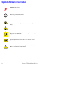
Symbols Marked on the Product
DANGER high voltage.
Protective ground (earth) symbol.
Hot surface on or in the printer. Use caution to avoid personal
injury.
0
The surface is hot while the printer is running. After turning off
the power, wait 30 minutes.
30 min.
Avoid pinching fingers in the printer. Use caution to avoid
personal injury.
Use caution (or draws attention to a particular component).
Refer to the manual(s) for information.
iv
Phaser 7750 Color Laser Printer
Power Safety Precautions
Power Source
For 110 VAC printers, do not apply more than 140 volts RMS between the supply
conductors or between either supply conductor and ground. Use only the specified
power cord and connector. For 220 VAC printers, do not apply more than 264 volts
RMS between the supply conductors or between either supply conductor and ground.
Use only the specified power cord. This manual assumes that the reader is a qualified
service technician.
Plug the three-wire power cord (with grounding prong) into a grounded AC outlet
only. If necessary, contact a licensed electrician to install a properly grounded outlet.
If the product loses its ground connection, contact with conductive parts may cause an
electrical shock.
Disconnecting Power
Turning the power off using the On/Off switch does not completely de-energize the
printer. You must also disconnect the printer power cord from the AC outlet. Position
the power cord so that it is easily accessible during servicing so that you may power
down the printer during an emergency.
Disconnect the power plug by pulling the plug, not the cord. Disconnect the power
cord in the following cases:
■
if the power cord or plug is frayed or otherwise damaged,
■
if any liquid or foreign material is spilled into the case,
■
if the printer is exposed to any excess moisture,
■
if the printer is dropped or damaged,
■
if you suspect that the product needs servicing or repair,
■
whenever you clean the product.
Service Manual
v
Electrostatic Discharge (ESD) Precautions
Some semiconductor components, and the respective sub-assemblies that contain
them, are vulnerable to damage by Electrostatic discharge (ESD). These components
include Integrated Circuits (ICs), Large-Scale Integrated circuits (LSIs), field-effect
transistors and other semiconductor chip components. The following techniques will
reduce the occurrence of component damage caused by static electricity.
Be sure the power is off to the chassis or circuit board, and observe all other safety
precautions.
■
Immediately before handling any semiconductor components assemblies, drain
the electrostatic charge from your body. This can be accomplished by touching an
earth ground source or by wearing a wrist strap device connected to an earth
ground source. Wearing a wrist strap will also prevent accumulation of additional
bodily static charges. Be sure to remove the wrist strap before applying power to
the unit under test to avoid potential shock.
■
After removing a static sensitive assembly from its anti-static bag, place it on a
grounded conductive surface. If the anti-static bag is conductive, you may ground
the bag and use it as a conductive surface.
■
Do not use freon-propelled chemicals. These can generate electrical charges
sufficient to damage some devices.
■
Do not remove a replacement component or electrical sub-assembly from its
protective package until you are ready to install it.
■
Immediately before removing the protective material from the leads of a
replacement device, touch the protective material to the chassis or circuit
assembly into which the device will be installed.
■
Minimize body motions when handling unpackaged replacement devices.
Motion such as your clothes brushing together, or lifting a foot from a carpeted
floor can generate enough static electricity to damage an electro-statically
sensitive device.
■
Handle IC’s and EEPROM’s carefully to avoid bending pins.
■
Pay attention to the direction of parts when mounting or inserting them on
Printed Circuit Boards (PCB’s).
vi
Phaser 7750 Color Laser Printer
Service Safety Summary
General Guidelines
For qualified service personnel only: Refer also to the preceding Power Safety
Precautions.
Avoid servicing alone: Do not perform internal service or adjustment of this
product unless another person capable of rendering first aid or resuscitation is present.
Use care when servicing with power: Dangerous voltages may exist at several
points in this product. To avoid personal injury, do not touch exposed connections and
components while power is on. Disconnect power before removing the power supply
shield or replacing components.
Do not wear jewelry: Remove jewelry prior to servicing. Rings, necklaces and
other metallic objects could come into contact with dangerous voltages and currents.
Power source: This product is intended to operate from a power source that will
not apply more then 264 volts RMS for a 220 volt AC outlet or 140 volts RMS for a
110 volt AC outlet between the supply conductors or between either supply conductor
and ground. A protective ground connection by way of the grounding conductor in
the power cord is essential for safe operation.
Warning Labels
Read and obey all posted warning labels. Throughout the printer, warning labels are
displayed on potentially dangerous components. As you service the printer, check to
make certain that all warning labels remain in place.
Safety Interlocks
Make sure all covers and the printer’s front panel are in place and all interlock
switches are functioning correctly after you have completed a printer service call. If
you bypass an interlock switch during a service call, use extreme caution when
working on or around the printer.
CLASS 1 LASER PRODUCT
The Phaser 7750 Color Laser Printer is certified to comply with Laser Product
Performance Standards set by the U.S. Department of Health and Human Services as
a Class 1 Laser Product. This means that this is a class of laser product that does not
emit hazardous laser radiation; this is possible only because the laser beam is totally
enclosed during all modes of customer operation. When servicing the printer or laser
unit, follow the procedures specified in this manual and there will be no hazards from
the laser.
Service Manual
vii
Servicing Electrical Components
Before starting any service procedure, switch off the printer power and unplug the
power cord from the wall outlet. If you must service the printer with power applied,
be aware of the potential for electrical shock.
Warning
Turning the power off by using the On/Off switch does not completely deenergize the printer. You must also disconnect the printer power cord from the
AC outlet. Position the power cord so that it is easily accessible during servicing.
Warning
Do not touch any electrical component unless you are instructed to do so by a
service procedure.
7500-117
Servicing Mechanical Components
When servicing mechanical components within the printer, manually rotate drive
assemblies, rollers, and gears.
Warning
Do not try to manually rotate or manually stop the drive assemblies while any
printer motor is running.
7500-118
Servicing Fuser Components
Warning
This printer uses heat to fuse the toner image to media. The Fuser Assembly is
VERY HOT. Turn the printer power off and wait at least 5 minutes for the Fuser
to cool before you attempt to service the Fuser Assembly or adjacent
components.
viii
Phaser 7750 Color Laser Printer
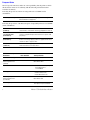
Regulatory Specifications
United States
The equipment described in this manual generates and uses radio frequency energy. If
it is not installed properly in strict accordance with Xerox’ instructions, it may cause
interference with radio and television reception or may not function properly due to
interference from another device. However, there is no guarantee that interference
will not occur in a particular installation. If this equipment does cause harmful
interference to radio or television reception, which can be determined by turning the
equipment off and on, the user is encouraged to try to correct the interference by one
or more of the following measures:
■
Reorient or relocate the receiver (device being interfered with).
■
Increase the separation between the printer and the receiver.
■
Connect the printer into an outlet on a circuit different from that which the
receiver is connected.
■
Route the interface cables on the printer away from the receiver.
■
Consult the dealer, Xerox service, or an experienced radio/television
technician for help.
Changes or modifications not expressly approved by Xerox can affect the emission
and immunity compliance and could void the user’s authority to operate this product.
To ensure compliance, use shielded interface cables. A shielded parallel cable can be
purchased directly from Xerox at www.xerox.com/office/supplies.
Xerox has tested this product to internationally accepted electromagnetic emission
and immunity standards. These standards are designed to mitigate interference caused
or received by this product in a normal office environment. This product is also
suitable for use in a residential environment based on the levels tested.
In the United States this product complies with the requirements of an unintentional
radiator in part 15 of the FCC rules. Operation is subject to the following two
conditions: (1) this device may not cause harmful interference; (2) this device must
accept any interference received, including interference that may cause undesired
operation.
Canada
This digital apparatus does not exceed the Class B limits for radio noise emissions
from digital apparatus set out in the Radio Interference Regulations of the Canadian
Department of Communications, ICES-003.
Le présent appareil numérique n'émet pas de bruits radioélectrique dépassant les
limits applicables aux appareils numériques de la classe B prescrites dans le
Réglement sur le brouillage radioélectrique édicté par le ministere des
Communications du Canada, NMB-003.
Service Manual
ix
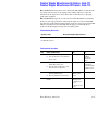
European Union
Xerox Corporation declares, under our sole responsibility, that the printer to which
this declaration relates is in conformity with the following standards and other
normative documents:
Following the provisions of the Low Voltage Directive 73/23/EEC and its
amendments:
EN 60950 (IEC 60950)
"Safety of Information Technology Equipment including
Electrical Business Equipment"
Following the provisions of the Electromagnetic Compatibility Directive 89/336/EEC
and its amendments:
EN 55022:1998
(CISPR 22)
"Limits and Methods of measurement of radio interference
characteristics of Information Technology Equipment." Class B.
EN 61000-3-2:1995
+A1:1998+A2:1998
(IEC61000-3-2)
"Part 3: Limits - Section 2: Limits for harmonic current
emissions (equipment input current less than or equal to 16A
per phase)."
EN 61000-3-3:1995
(IEC61000-3-3)
"Part 3: Limits - Section 3: Limitation of voltage fluctuations and
flicker in low-voltage supply systems for equipment with rated
current less than or equal to 16A."
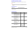
EN 55024:1998
(CISPR 24)
"Information technology equipment - Immunity characteristics Limits and methods of measurement. "
CISPR 24 Immunity
Phenomena
Basic Standard
Test Specification
Electrostatic Discharge
IEC 61000-4-2:1995
6 kV Contact, 10 kV Air
Radio-Frequency
Electromagnetic Field
(radiated)
IEC 61000-4-3:1995
80-1000 MHz, 3 V/m,
80% AM @ 1 KHz
Fast Burst Transients
IEC 61000-4-4:1995
5/50 Tr/Th ns, 5 kHz Rep. Freq
0.5 kV Signal Lines
1 kV AC Mains
Line Surge
IEC 61000-4-5:1995
Combination wave
2.0 kV Common mode
2.0 kV Differential mode
Radio-Frequency
Electromagnetic Field
(Conducted)
IEC 61000-4-6:1996
0.15 - 80 MHz, 3 V,
80% AM @ 1 kHz
Line voltage dips
IEC 61000-4-11:1994
>95% dip for ½ cycle @ 50 Hz
30% dip for 25 cycles @ 50 Hz
x
Phaser 7750 Color Laser Printer
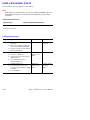
CISPR 24 Immunity
Phenomena
Line voltage drop-out
Basic Standard
Test Specification
IEC 61000-411:1994
>95% dropout for 250 cycles
@ 50 Hz
This product, if used properly in accordance with the user’s instructions, is neither
dangerous for the consumer nor for the environment.
A signed copy of the Declaration of Conformity for this product can be obtained from
Xerox.
Service Manual
xi
xii
Phaser 7750 Color Laser Printer
Contents
Service Terms . . . . . . . . . . . . . . . . . . . . . . . . . . . . . . . . . . . . . . . . . . . . . . .iii
Symbols Marked on the Product . . . . . . . . . . . . . . . . . . . . . . . . . . . . . . . . .iv
Power Safety Precautions . . . . . . . . . . . . . . . . . . . . . . . . . . . . . . . . . . . . . . v
Electrostatic Discharge (ESD) Precautions . . . . . . . . . . . . . . . . . . . . . . . . .vi
Service Safety Summary . . . . . . . . . . . . . . . . . . . . . . . . . . . . . . . . . . . . . . vii
Regulatory Specifications . . . . . . . . . . . . . . . . . . . . . . . . . . . . . . . . . . . . . .ix
1 General Information
Printer Introduction and Overview . . . . . . . . . . . . . . . . . . . . . . . . . . . . . . 1-2
Phaser 7750 Printer Configurations. . . . . . . . . . . . . . . . . . . . . . . . . . . . . 1-3
Parts of the Printer . . . . . . . . . . . . . . . . . . . . . . . . . . . . . . . . . . . . . . . . . 1-4
Exterior - Front View. . . . . . . . . . . . . . . . . . . . . . . . . . . . . . . . . . . 1-4
Exterior - Rear View . . . . . . . . . . . . . . . . . . . . . . . . . . . . . . . . . . . 1-5
Phaser 7750 Front Panel Configuration . . . . . . . . . . . . . . . . . . . . . . . . . . 1-6
Image Processor Board and Rear Panel Host Interface . . . . . . . . . . . . . . 1-7
Routine Maintenance Items and Consumables . . . . . . . . . . . . . . . . . . . . 1-8
Printer Specifications. . . . . . . . . . . . . . . . . . . . . . . . . . . . . . . . . . . . . . . . 1-9
Physical Dimensions and Clearances . . . . . . . . . . . . . . . . . . . . . . 1-9
Mounting Surface Specification . . . . . . . . . . . . . . . . . . . . . . . . . 1-10
Functional Specifications . . . . . . . . . . . . . . . . . . . . . . . . . . . . . . 1-12
Electrical Specifications . . . . . . . . . . . . . . . . . . . . . . . . . . . . . . . 1-12
Environmental Specifications . . . . . . . . . . . . . . . . . . . . . . . . . . . 1-13
Media and Tray Specifications . . . . . . . . . . . . . . . . . . . . . . . . . . 1-13
2 Theory of Operation
Summary of the Phaser 7750 Print Process . . . . . . . . . . . . . . . . . . . . . . 2-2
Paper Path of the Printer . . . . . . . . . . . . . . . . . . . . . . . . . . . . . . . . . . . . . 2-4
Paper Size Sensing. . . . . . . . . . . . . . . . . . . . . . . . . . . . . . . . . . . . 2-5
Paper Feeding and Sensing . . . . . . . . . . . . . . . . . . . . . . . . . . . . . 2-5
Fuser . . . . . . . . . . . . . . . . . . . . . . . . . . . . . . . . . . . . . . . . . . . . . . 2-8
EAHG Toner . . . . . . . . . . . . . . . . . . . . . . . . . . . . . . . . . . . . . . . . . . . . . . . 2-9
Technology Overview. . . . . . . . . . . . . . . . . . . . . . . . . . . . . . . . . . . . . . . 2-10
Standby Power . . . . . . . . . . . . . . . . . . . . . . . . . . . . . . . . . . . . . . 2-10
Machine Run Control and NVRAM . . . . . . . . . . . . . . . . . . . . . . . 2-10
Drive Power . . . . . . . . . . . . . . . . . . . . . . . . . . . . . . . . . . . . . . . . 2-11
System Power Supplies . . . . . . . . . . . . . . . . . . . . . . . . . . . . . . . 2-13
ROS and Regicon Technology Overview . . . . . . . . . . . . . . . . . . . . . . . . 2-15
Write Black Process . . . . . . . . . . . . . . . . . . . . . . . . . . . . . . . . . . 2-15
RegiCon Overview . . . . . . . . . . . . . . . . . . . . . . . . . . . . . . . . . . . . . . . . . 2-17
#1 Skew (Fine) Setup . . . . . . . . . . . . . . . . . . . . . . . . . . . . . . . . . 2-19
#2 IN/OUT Setup . . . . . . . . . . . . . . . . . . . . . . . . . . . . . . . . . . . . 2-19
#3 Center Setup . . . . . . . . . . . . . . . . . . . . . . . . . . . . . . . . . . . . . 2-19
Service Manual
xiii
#4 Skew (Rough) Setup. . . . . . . . . . . . . . . . . . . . . . . . . . . . . . .
View the RegiCon Patterns. . . . . . . . . . . . . . . . . . . . . . . . . . . . .
Sensors . . . . . . . . . . . . . . . . . . . . . . . . . . . . . . . . . . . . . . . . . . . . . . . . .
ATC Sensors . . . . . . . . . . . . . . . . . . . . . . . . . . . . . . . . . . . . . . .
ADC Sensor . . . . . . . . . . . . . . . . . . . . . . . . . . . . . . . . . . . . . . . .
ADC Output Check . . . . . . . . . . . . . . . . . . . . . . . . . . . . . . . . . . .
Lower Tray Feeders Sensor and Board Locations . . . . . . . . . . .
2-19
2-20
2-22
2-24
2-25
2-26
2-28
3 Error Messages and Codes
Introduction. . . . . . . . . . . . . . . . . . . . . . . . . . . . . . . . . . . . . . . . . . . . . . . 3-2
Accessing the Printer’s Error History . . . . . . . . . . . . . . . . . . . . . . 3-2
Service Checklist . . . . . . . . . . . . . . . . . . . . . . . . . . . . . . . . . . . . . 3-3
Service RIP (Every Call) Procedures . . . . . . . . . . . . . . . . . . . . . . 3-4
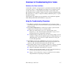
Overview for Troubleshooting Error Codes . . . . . . . . . . . . . . . . . . . . . . . 3-5
Using the Troubleshooting Procedures . . . . . . . . . . . . . . . . . . . . 3-5
System Startup and POST . . . . . . . . . . . . . . . . . . . . . . . . . . . . . . . . . . . . 3-7
Power On Self Test (POST) . . . . . . . . . . . . . . . . . . . . . . . . . . . . . 3-7
POST Faults . . . . . . . . . . . . . . . . . . . . . . . . . . . . . . . . . . . . . . . . . 3-8
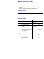
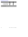
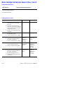
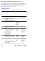
Error Messages and Codes Index Table. . . . . . . . . . . . . . . . . . . . . . . . . 3-10
Error Messages and Codes Procedures. . . . . . . . . . . . . . . . . . . . . . . . . 3-12
Black ATC Sensor Failure, Code 15 . . . . . . . . . . . . . . . . . . . . . . 3-15
Transfer Roller Contact Failure, Code 20
Transfer Roller Retract Failure, Code 21. . . . . . . . . . . . . . . . 3-17
1st BTR Contact or Retract Failure. . . . . . . . . . . . . . . . . . . . . . . 3-18
Accumulator Belt Home Position Took Too Long, Code 30
Accumulator Belt Home Position Failure, Code 31 . . . . . . . . 3-19
Accumulator Belt Edge Sensor Failure, Code 32
Accumulator Belt Drive Logic Failure, Code 34 . . . . . . . . . . 3-22
Unexpected Accumulator Belt Home Sensor Signal, Code 33 . . 3-24
Fuser Main Lamp Failure, Code 35. . . . . . . . . . . . . . . . . . . . . . . 3-25
Install or Reseat Fuser, Code 41 . . . . . . . . . . . . . . . . . . . . . . . . 3-26
Fuser STS (Front) Warm Time Failure, Code 42. . . . . . . . . . . . . 3-27
Fuser SSR1 On Time Failure, Code 43 . . . . . . . . . . . . . . . . . . . . 3-27
Fuser Sub Lamp Overheat Failure, Code 44 . . . . . . . . . . . . . . . . 3-29
Fuser STS (Rear) Failure, Code 45 . . . . . . . . . . . . . . . . . . . . . . . 3-30
Fuser STS (Rear) Warm Time Failure, Code 46 . . . . . . . . . . . . . 3-31
Fuser SSR2 On Time Failure, Code 47 . . . . . . . . . . . . . . . . . . . . 3-31
Fan Failure, Code 48 . . . . . . . . . . . . . . . . . . . . . . . . . . . . . . . . . 3-33
Imaging Unit Motor Failure, Code 60 . . . . . . . . . . . . . . . . . . . . . 3-35
Imaging Unit [1] [2] [3] [4] Communications Failure,
Code 70, 71, 72, 73 . . . . . . . . . . . . . . . . . . . . . . . . . . . . . . . 3-36
Black Imaging Unit Motor Failure. . . . . . . . . . . . . . . . . . . . . . . . 3-37
Waste Cartridge Full Detection Sensor Failure, Code 78 . . . . . . 3-38
Engine Logic Board Failure, Code 80 . . . . . . . . . . . . . . . . . . . . . 3-39
Controller to Engine Communications Failure, Code 81 . . . . . . . 3-39
Engine Logic Board RAM/ROM Failure, Code 82 . . . . . . . . . . . . 3-39
xiv
Phaser 7750 Printer
Engine Logic Board NVRAM Failure, Code 83 . . . . . . . . . . . . . .
Controller to Engine Logic Board Time Failure, Code 84 . . . . . .
Engine Logic Board Micro Pitch Failure, Code 85. . . . . . . . . . . .
High-Voltage Power Supply Failure, Code 86 . . . . . . . . . . . . . . .
Tray Lift Failure, Code 87 . . . . . . . . . . . . . . . . . . . . . . . . . . . . . .
Tray 1/MPT Size Sensor (7-274), Code? . . . . . . . . . . . . . . . . . .
Lower Tray Communication Failure, Code 88. . . . . . . . . . . . . . .
Reflective Sensor Procedure . . . . . . . . . . . . . . . . . . . . . . . . . . .
Transmissive Sensor Procedure. . . . . . . . . . . . . . . . . . . . . . . . .
Finisher Stapler Move Sensor On Failure, Code 111
Finisher Stapler Move Sensor Off Failure, Code 112. . . . . . .
Finisher Stapler Failure, Code 113 . . . . . . . . . . . . . . . . . . . . . . .
Front Tamper Home Sensor Failure, Code 114. . . . . . . . . . . . . .
Rear Tamper Home Sensor Failure, Code 115 . . . . . . . . . . . . . .
Finisher Stacker Height Sensor Off Failure, Code 116 . . . . . . . .
Finisher Stacker Tray Failure, Code 117 . . . . . . . . . . . . . . . . . . .
Finisher Stapler Front Corner On Failure, Code 118
Finisher Stapler Front Corner Off Failure, Code 119 . . . . . . .
Finisher Eject Clamp Home Sensor On Failure, Code 120
Finisher Eject Clamp Home Sensor Off Failure, Code 121. . .
Finisher Decurler Failure, Code 122 . . . . . . . . . . . . . . . . . . . . . .
Finisher Set Clamp Failure, Code 123. . . . . . . . . . . . . . . . . . . . .
Finisher Communication Failure, Code 124 . . . . . . . . . . . . . . . .
Finisher Staple Mode Logic Failure, Code 125 . . . . . . . . . . . . . .
3-40
3-40
3-40
3-40
3-41
3-43
3-44
3-45
3-46
3-47
3-49
3-51
3-52
3-53
3-55
3-57
3-58
3-59
3-60
3-61
3-61
4 General Troubleshooting
Introduction . . . . . . . . . . . . . . . . . . . . . . . . . . . . . . . . . . . . . . . . . . . . . . . 4-2
Service Diagnostics . . . . . . . . . . . . . . . . . . . . . . . . . . . . . . . . . . . . . . . . . 4-2
Service Diagnostic Front Panel Button Descriptions. . . . . . . . . . . 4-3
Service Diagnostic Tests Table. . . . . . . . . . . . . . . . . . . . . . . . . . . 4-3
Front Panel Troubleshooting . . . . . . . . . . . . . . . . . . . . . . . . . . . . . . . . . 4-14
The Printer Does Not Come to a “Ready” State . . . . . . . . . . . . . 4-14
Inoperable Printer Troubleshooting . . . . . . . . . . . . . . . . . . . . . . . . . . . . 4-15
Troubleshooting Power Supplies and Interlocks . . . . . . . . . . . . . . . . . . 4-16
Troubleshooting AC Power. . . . . . . . . . . . . . . . . . . . . . . . . . . . . 4-16
Troubleshooting the Low-Voltage Power Supplies. . . . . . . . . . . 4-17
Troubleshooting the +3.3 VDC and
(2) +5 VDC Low-Voltage Power Supplies . . . . . . . . . . . . . . . 4-18
Troubleshooting the 24 VDC LVPS. . . . . . . . . . . . . . . . . . . . . . . 4-18
Interlock Circuit Diagram . . . . . . . . . . . . . . . . . . . . . . . . . . . . . . 4-19
Media Jams and the Paper Path . . . . . . . . . . . . . . . . . . . . . . . . . . . . . . 4-21
Media-Based Problems . . . . . . . . . . . . . . . . . . . . . . . . . . . . . . . 4-21
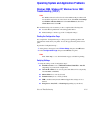
Operating System and Application Problems. . . . . . . . . . . . . . . . . . . . . 4-23
Windows 2000, Windows XP, Windows Server 2003
Troubleshooting (TCP/IP). . . . . . . . . . . . . . . . . . . . . . . . . . . 4-23
Windows NT 4.x Troubleshooting (TCP/IP) . . . . . . . . . . . . . . . . 4-24
Service Manual
xv
Windows 98 and Windows Me Troubleshooting . . . . . . . . . . . . 4-25
Macintosh Troubleshooting . . . . . . . . . . . . . . . . . . . . . . . . . . . 4-27
Novell NetWare Troubleshooting . . . . . . . . . . . . . . . . . . . . . . . . 4-28
5 Print-Quality Troubleshooting
Print-Quality Problems Overview. . . . . . . . . . . . . . . . . . . . . . . . . . . . . . . 5-2
Defects Associated with Specific Printer Components. . . . . . . . . 5-2
Front Panel Test Prints . . . . . . . . . . . . . . . . . . . . . . . . . . . . . . . . . . . . . . 5-4
Troubleshooting Print-Quality Page . . . . . . . . . . . . . . . . . . . . . . . 5-4
Color Test Pages . . . . . . . . . . . . . . . . . . . . . . . . . . . . . . . . . . . . . 5-5
Analyzing the Test Pattern . . . . . . . . . . . . . . . . . . . . . . . . . . . . . . 5-6
Solid Fill Pages . . . . . . . . . . . . . . . . . . . . . . . . . . . . . . . . . . . . . . 5-7
Repeating Defects Page . . . . . . . . . . . . . . . . . . . . . . . . . . . . . . . . 5-8
Remove Print Smears . . . . . . . . . . . . . . . . . . . . . . . . . . . . . . . . . 5-8
Engine Test Prints . . . . . . . . . . . . . . . . . . . . . . . . . . . . . . . . . . . . . . . . . . 5-9
Paper Path Options . . . . . . . . . . . . . . . . . . . . . . . . . . . . . . . . . . . 5-9
Print Laser Check. . . . . . . . . . . . . . . . . . . . . . . . . . . . . . . . . . . . . 5-9
Print Halftones . . . . . . . . . . . . . . . . . . . . . . . . . . . . . . . . . . . . . . 5-10
Print Grid 1-Dot . . . . . . . . . . . . . . . . . . . . . . . . . . . . . . . . . . . . . 5-10
Print Fast Scan 8 Tone . . . . . . . . . . . . . . . . . . . . . . . . . . . . . . . . 5-11
Initial Actions Before troubleshooting any Print-Quality Problems: . . . . 5-12
6 Adjustments and Calibrations
Registration Control (RegiCon) Adjustment Overview . . . . . . . . . . . . . . . 6-2
Coarse and Fine Skew Adjustments . . . . . . . . . . . . . . . . . . . . . . . 6-3
In/Out Skew Adjustment . . . . . . . . . . . . . . . . . . . . . . . . . . . . . . . 6-3
Center Skew Adjustment . . . . . . . . . . . . . . . . . . . . . . . . . . . . . . . 6-4
RegiCon Adjustment Procedures. . . . . . . . . . . . . . . . . . . . . . . . . . . . . . . 6-5
RegiCon #1 Fine Skew Adjustment . . . . . . . . . . . . . . . . . . . . . . . 6-7
RegiCon #2 In/Out Skew Adjustment . . . . . . . . . . . . . . . . . . . . . . 6-8
RegiCon #3 Center Skew Adjustment . . . . . . . . . . . . . . . . . . . . . 6-9
RegiCon #4 Coarse Skew Adjustment . . . . . . . . . . . . . . . . . . . . 6-10
Coarse RegiCon Initialization . . . . . . . . . . . . . . . . . . . . . . . . . . . 6-12
ATC Sensor Setup . . . . . . . . . . . . . . . . . . . . . . . . . . . . . . . . . . . . . . . . . 6-14
Additional Information . . . . . . . . . . . . . . . . . . . . . . . . . . . . . . . . 6-15
Resetting NVRAM . . . . . . . . . . . . . . . . . . . . . . . . . . . . . . . . . . . . . . . . . 6-16
PostScript NVRAM Resets . . . . . . . . . . . . . . . . . . . . . . . . . . . . . 6-16
Service Diagnostics NVRAM Resets . . . . . . . . . . . . . . . . . . . . . . . . . . . 6-19
PostScript NVRAM Reset. . . . . . . . . . . . . . . . . . . . . . . . . . . . . . 6-19
Clear Tech Rep Faults . . . . . . . . . . . . . . . . . . . . . . . . . . . . . . . . . . . . . . 6-20
7 Cleaning and Maintenance
Service Preventive Maintenance Procedure. . . . . . . . . . . . . . . . . . . . . . . 7-2
Cleaning . . . . . . . . . . . . . . . . . . . . . . . . . . . . . . . . . . . . . . . . . . . . . . . . . 7-2
xvi
Phaser 7750 Printer
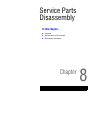
8 Service Parts Disassembly
Overview . . . . . . . . . . . . . . . . . . . . . . . . . . . . . . . . . . . . . . . . . . . . . . . . . 8-2
Standard Orientation of the Printer for Disassembly . . . . . . . . . . 8-2
General Notes on Disassembly . . . . . . . . . . . . . . . . . . . . . . . . . . . . . . . . 8-3
Print Engine . . . . . . . . . . . . . . . . . . . . . . . . . . . . . . . . . . . . . . . . . 8-4
Optional Lower Trays . . . . . . . . . . . . . . . . . . . . . . . . . . . . . . . . . 8-57
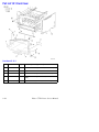
9 Service Parts Lists
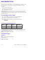
Serial Number Format . . . . . . . . . . . . . . . . . . . . . . . . . . . . . . . . . . . . . . . 9-2
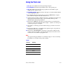
Using the Parts List . . . . . . . . . . . . . . . . . . . . . . . . . . . . . . . . . . . . . . . . . 9-3
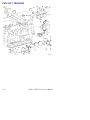
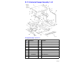
Parts List 1.1 Drive Unit . . . . . . . . . . . . . . . . . . . . . . . . . . . . . . . . 9-4
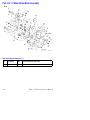
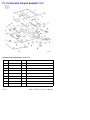
Part List 1.2 Main Drive Motor Assembly. . . . . . . . . . . . . . . . . . . 9-6
Part List 1.3 Steering Motor and MOB . . . . . . . . . . . . . . . . . . . . . 9-7
Part List 2.1 Tray 2 . . . . . . . . . . . . . . . . . . . . . . . . . . . . . . . . . . . 9-8
Part List 2.3 Tray Feeder and Left Lower Cover Assy . . . . . . . . . . 9-9
Part List 2.4 Tray 2 Feeder . . . . . . . . . . . . . . . . . . . . . . . . . . . . . 9-10
Part List 2.6 Registration Transport . . . . . . . . . . . . . . . . . . . . . . 9-11
Part List 2.7 Left Cover Unit . . . . . . . . . . . . . . . . . . . . . . . . . . . 9-12
Part List 2.8 Left Cover Assembly: 1 of 2 . . . . . . . . . . . . . . . . . . 9-13
Part List 2.9 Left Cover Assembly: 2of 2 . . . . . . . . . . . . . . . . . . 9-14
Part List 2.10 Exit Transport Assembly . . . . . . . . . . . . . . . . . . . 9-15
Part List 2.12 Tray 1: 1 of 2 . . . . . . . . . . . . . . . . . . . . . . . . . . . . 9-16
Part List 2.13 Tray 1: 2 of 2 . . . . . . . . . . . . . . . . . . . . . . . . . . . . 9-17
Part List 2.14 Tray 1 Feed Assembly . . . . . . . . . . . . . . . . . . . . . 9-18
Part List 3.1 Laser (ROS) Assembly. . . . . . . . . . . . . . . . . . . . . . 9-19
Part List 4.1 Xerographic Module: 1 of 2 . . . . . . . . . . . . . . . . . . 9-20
Part List 4.2 Xerographic Module: 2 of 2 . . . . . . . . . . . . . . . . . . 9-21
Part List 5.1 Lift Unit . . . . . . . . . . . . . . . . . . . . . . . . . . . . . . . . . 9-22
Part List 5.2 Accumulator Belt Assembly . . . . . . . . . . . . . . . . . . 9-24
Part List 5.6 Accumulator Belt Elevator . . . . . . . . . . . . . . . . . . . 9-25
Part List 6.1 Developer Unit: 1 of 2 . . . . . . . . . . . . . . . . . . . . . . 9-26
Part List 6.2 Developer Unit: 2 of 2 . . . . . . . . . . . . . . . . . . . . . . 9-28
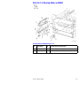
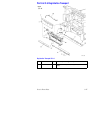
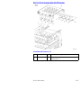
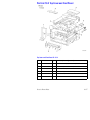
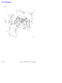
Part List 7.1 Fuser Assembly . . . . . . . . . . . . . . . . . . . . . . . . . . . 9-29
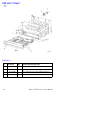
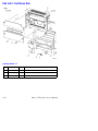
Part List 8.1 Air System . . . . . . . . . . . . . . . . . . . . . . . . . . . . . . . 9-30
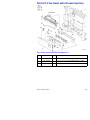
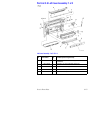
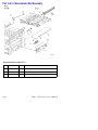
Part List 9.1 Electrical Components: 1 of 3 . . . . . . . . . . . . . . . . 9-32
Part List 9.2 Electrical Components: 2 of 3 . . . . . . . . . . . . . . . . 9-34
Part List 9.3 Electrical Components: 3 of 3 . . . . . . . . . . . . . . . . 9-35
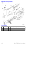
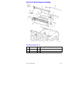
Part List 10.1 Front Cover . . . . . . . . . . . . . . . . . . . . . . . . . . . . . 9-36
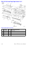
Part List 10.2 Top Cover and Front Panel. . . . . . . . . . . . . . . . . . 9-37
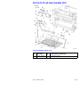
Part List 10.3 Rear Cover . . . . . . . . . . . . . . . . . . . . . . . . . . . . . . 9-38
Part List 11.1 Inverter Transport . . . . . . . . . . . . . . . . . . . . . . . . 9-39
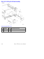
Part List 12.1 Duplex Unit Assembly . . . . . . . . . . . . . . . . . . . . . 9-40
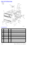
Part List 13.1 Image Processor and Engine Control Boards . . . 9-41
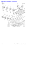
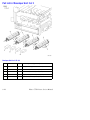
Part List 16.1 Lower Trays 3/4/5 Assembly . . . . . . . . . . . . . . . . 9-42
Part List 16.5 Lower Trays Paper Feeder: 1 of 2 . . . . . . . . . . . . 9-43
Part List 16.6 Lower Trays Paper Feeder: 2 of 2 . . . . . . . . . . . . 9-44
Service Manual
xvii
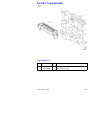
Part List 16.13 Left Cover Assembly (LTD) . . . . . . . . . . . . . . . .
Part List 16.14 Tray 4/5 Lift Gear Assembly . . . . . . . . . . . . . . .
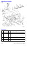
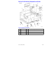
Part List 16.15 Electrical Components and Caster . . . . . . . . . . .
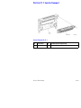
Part List 16.16 Lower Tray Deck . . . . . . . . . . . . . . . . . . . . . . . .
Hardware Kits . . . . . . . . . . . . . . . . . . . . . . . . . . . . . . . . . . . . . .
9-45
9-46
9-47
9-48
9-49
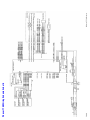
10 Wiring Diagrams
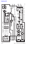
Plug/Jack Locations . . . . . . . . . . . . . . . . . . . . . . . . . . . . . . . . . . . . . . . 10-2
Plug/Jack Locator Maps . . . . . . . . . . . . . . . . . . . . . . . . . . . . . . . . . . . 10-10
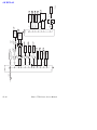
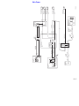
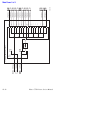
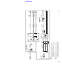
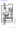
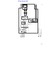
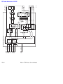
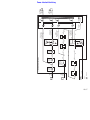
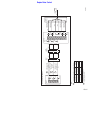
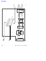
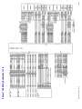
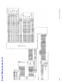
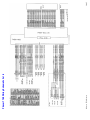
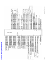
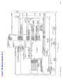
Wiring Diagrams . . . . . . . . . . . . . . . . . . . . . . . . . . . . . . . . . . . . . . . . . 10-29
11 Phaser 7750 Finisher
Phaser 7750 Finisher. . . . . . . . . . . . . . . . . . . . . . . . . . . . . . . . . . . . . . . 11-2
Finisher Overview. . . . . . . . . . . . . . . . . . . . . . . . . . . . . . . . . . . . 11-2
Finisher Specifications. . . . . . . . . . . . . . . . . . . . . . . . . . . . . . . . . . . . . . 11-3
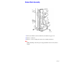
Finisher Assemblies. . . . . . . . . . . . . . . . . . . . . . . . . . . . . . . . . . . . . . . . 11-5
Internal Assemblies of the Finisher . . . . . . . . . . . . . . . . . . . . . . 11-6
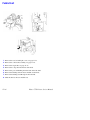
Horizontal Transport Sensor, Interlock and Switch Locations . . 11-7
Finisher Sensor, Interlock and Switch Locator Map . . . . . . . . . 11-8
Finisher Sensor, Interlock and Switch Locator Map. . . . . . . . . . 11-9
Finisher Disassembly. . . . . . . . . . . . . . . . . . . . . . . . . . . . . . . . . . . . . . 11-10
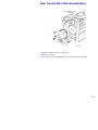
Horizontal Transport Assembly . . . . . . . . . . . . . . . . . . . . . . . . 11-11
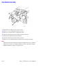
Horizontal Transport Top Open, Front, and Rear Cover . . . . . . 11-12
Horizontal Transport Entrance Upper Cover Assembly . . . . . . 11-13
Horizontal Transport Belts . . . . . . . . . . . . . . . . . . . . . . . . . . . . 11-14
Horizontal Transport Entrance Sensor and
Top Tray Full Sensor . . . . . . . . . . . . . . . . . . . . . . . . . . . . . 11-15
Gate-In Solenoid Assembly . . . . . . . . . . . . . . . . . . . . . . . . . . . 11-16
Finisher Covers . . . . . . . . . . . . . . . . . . . . . . . . . . . . . . . . . . . . 11-17
Stack Height-Sensor Assembly . . . . . . . . . . . . . . . . . . . . . . . . 11-19
Stacker Paper-Sensor Assembly . . . . . . . . . . . . . . . . . . . . . . . 11-20
Set Clamp Clutch and Gear . . . . . . . . . . . . . . . . . . . . . . . . . . . 11-21
Eject Roll Assembly . . . . . . . . . . . . . . . . . . . . . . . . . . . . . . . . . 11-22
Finisher Control Board, Bracket and Shield . . . . . . . . . . . . . . . 11-23
Stacker Motor Assembly . . . . . . . . . . . . . . . . . . . . . . . . . . . . . 11-25
Paddle Shaft. . . . . . . . . . . . . . . . . . . . . . . . . . . . . . . . . . . . . . . 11-26
Paper Transport Motor (Motor Assembly Main) . . . . . . . . . . . 11-27
Cam Bracket Assembly . . . . . . . . . . . . . . . . . . . . . . . . . . . . . . 11-28
Staple Unit Assembly and Motor . . . . . . . . . . . . . . . . . . . . . . . 11-29
Compiler Tray . . . . . . . . . . . . . . . . . . . . . . . . . . . . . . . . . . . . . 11-30
Finisher Wiring Diagrams . . . . . . . . . . . . . . . . . . . . . . . . . . . . . . . . . . 11-31
Finisher Service Parts List . . . . . . . . . . . . . . . . . . . . . . . . . . . . . . . . . . 11-42
PL 17.1 Finisher. . . . . . . . . . . . . . . . . . . . . . . . . . . . . . . . . . . . 11-42
PL 17.2 Gate Assembly . . . . . . . . . . . . . . . . . . . . . . . . . . . . . . 11-44
PL 17.3 Horizontal Transport Assembly: 1 of 2 . . . . . . . . . . . . 11-45
PL 17.4 Horizontal Transport Assembly: 2 of 2 . . . . . . . . . . . . 11-46
xviii
Phaser 7750 Printer
PL 17.5 Covers. . . . . . . . . . . . . . . . . . . . . . . . . . . . . . . . . . . . .
PL 17.6 Top Cover and Eject Roll . . . . . . . . . . . . . . . . . . . . . . .
PL 17.7 Paper Transport: 1 of 2 . . . . . . . . . . . . . . . . . . . . . . . .
PL 17.8 Paper Transport: 2 of 2 . . . . . . . . . . . . . . . . . . . . . . . .
PL 17.9 Staple Unit Assembly . . . . . . . . . . . . . . . . . . . . . . . . .
PL 17.10 Compiler Tray Assembly . . . . . . . . . . . . . . . . . . . . . .
PL 17.11 Stacker Elevator Assembly. . . . . . . . . . . . . . . . . . . .
PL 17.12 Exit Assembly. . . . . . . . . . . . . . . . . . . . . . . . . . . . . .
PL 17.13 Electrical Components . . . . . . . . . . . . . . . . . . . . . . .
PL 17.14 Finisher Rack (Stand) . . . . . . . . . . . . . . . . . . . . . . . .
11-48
11-50
11-52
11-54
11-56
11-58
11-60
11-62
11-64
11-66
A Appendix
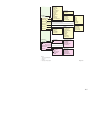
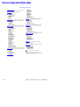
Menu Map . . . . . . . . . . . . . . . . . . . . . . . . . . . . . . . . . . . . . . . . . . . . . . . . A-2
Service Diagnostic Menu Map . . . . . . . . . . . . . . . . . . . . . . . . . . . . . . . . . A-4
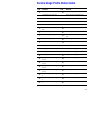
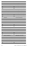
Service Usage Profile Status Codes . . . . . . . . . . . . . . . . . . . . . . . . . . . . . A-5
Missing Chain Link Codes Definitions . . . . . . . . . . . . . . . . . . . . . . . . . . A-11
Paper Weight Equivalence Table . . . . . . . . . . . . . . . . . . . . . . . . . . . . . . A-12
Index
Service Manual
xix
xx
Phaser 7750 Printer
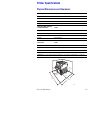
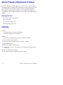
General
Information
In this chapter...
■
Phaser 7750 Printer Configurations
■
Parts of the Printer
■
Phaser 7750 Front Panel Configuration
■
Image Processor Board and Rear Panel Host Interface
■
Routine Maintenance Items and Consumables
■
Printer Specifications
Chapter
1
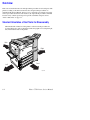
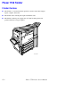
Printer Introduction and Overview
The Xerox Phaser 7750 Color Laser Printer Service Manual is the primary document
used for repairing, maintaining, and troubleshooting the printer.
To ensure understanding of this product, complete the Xerox Phaser 7750 Printer
Multi-Media Service Training and Self-Study Guide.
7750-234
1-2
Phaser 7750 Printer Service Manual
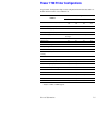
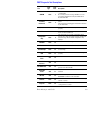
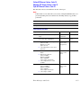
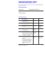
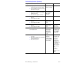
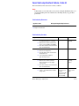
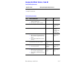
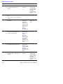
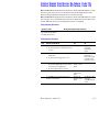
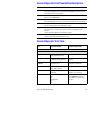
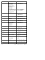
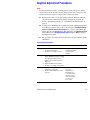
Phaser 7750 Printer Configurations
A replaceable “Configuration Chip” holds configuration information that enables or
disables built-in features as described below.
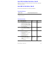
Printer Configurations
Features
7750B
Processor and Clock Rate (Mhz)
Max Print Speed (Letter/A4)
Maximum Memory (GB)
Memory Configuration (MB)
Resolutions (dpi)
7750DN
7750GX
7750DXF
G4
715
G4
715
G4
715
G4
715
35/35
35/35
35/35
35/35
1
1
1
1
256
384
512
512
Base memory allows 1200 x 1200 dpi, full-clip path
A3 image.
Post Script Fonts
137
137
137
137
PCL5c Fonts
81
81
81
81
Direct PDF 1.4 Support
Std
Std
Std
Std
Job Pipelining
Std
Std
Std
Std
Hard Drive Productivity Features*
N/A*
Std
Std
Std
Full-Bleed Capability and Banner-Size*
Printing
N/A*
Std
Std
Std
Photo Mode*
N/A*
Std
Std
Std
Automatic 2-Sided Printing*
N/A*
Std
Std
Std
1500-Sheet Lower Tray Deck
Opt
Opt
Std
N/A
2500-Sheet High-Capacity Feeder
Opt
Opt
N/A
Std
Ethernet Interface (Networking)
N/A*
10/100
10/100
10/100
USB 2.0
Std
Std
Std
Std
Hard Drive
Std
Std
Std
Std
Finisher
N/A
Opt
Opt
Std
PhaserMatch Version 3.0 Software
N/A
Opt
Std
Std
PhaserCal Software
Opt
Std
Std
Std
*Requires 7750B to 7750DN upgrade.
General Information
1-3
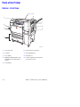
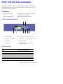
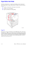
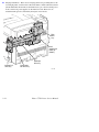
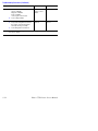
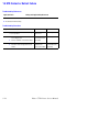
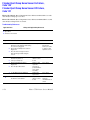
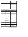
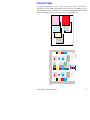
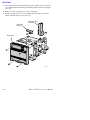
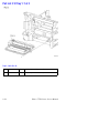
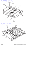
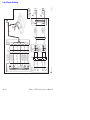
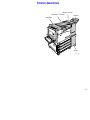
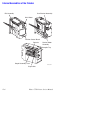
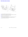
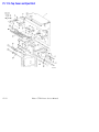
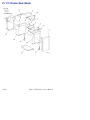
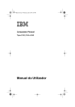
Parts of the Printer
Exterior - Front View
5
6
1
7
2
8
3
9
4
7750-445
1. Face Down Tray
6. Finisher Top Door H Release
2. Front Door
7. Finisher Output Tray
3. Tray 1 (MPT)
8. Finisher Door J
4. 2500-Sheet High-Capacity Feeder
(1500-Sheet Lower Tray Deck not
shown)
9. Front Door right side release (release
on left side not shown
5. Power Switch
1-4
Phaser 7750 Printer Service Manual
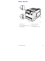
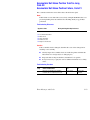
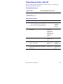
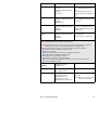
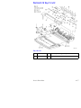
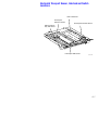
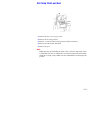
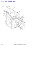
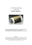
Exterior - Rear View
1
5
2
6
3
4
7750-446
1. USB Connection
4. AC Power Cord Connection
2. Ethernet 10/100 Base-T Connection
5. Latch for Left Door A
3. GFI Reset Button
6. Tray 1 (MPT) in closed position
General Information
1-5
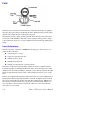
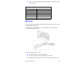
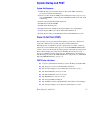
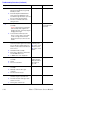
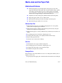
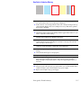
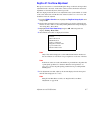
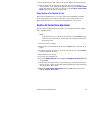
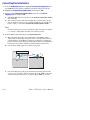
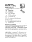
Phaser 7750 Front Panel Configuration
The printer’s front panel consists of one LED, a display window, and six buttons.
These buttons are used to navigate the menu system, perform functions, and select
modes of operation for the printer.
LED Indicators:
■
Green = Ready to Print
■
Flashing Green = Receiving, Processing Data,
Printing or Power Saver Mode
■
Flashing Yellow = Warning
■
Flashing Red (Continuously) = Error
Front Panel Button Descriptions
3
5
4
6
Phaser 7750
Tray 2 Paper Type
Plain Paper
Heavy Plain Paper
Phaser Series-25 Premium
Transparency
Exit
1
2
7
8
7750-447
1
LED (Power/Status)
5
Up button - scrolls up the menu system
2
Graphic front panel display
6
Down button - scrolls down the menu system
3
Cancel button
7
OK (select) button
4
Back button
8
Information “i” button - for additional
explanation or help
Front Panel Shortcuts
Mode
Press this selection at Power On
Skip execution of POST diagnostics
OK
Print Service Diagnostics Map
INFO
Reset PostScript NVRAM
BACK+OK
Password Bypass
UP+DOWN
Enter Service Diagnostics
BACK+INFO
1-6
Phaser 7750 Printer Service Manual
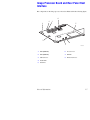
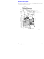
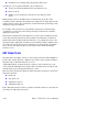
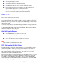
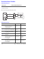
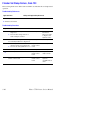
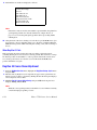
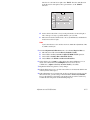
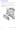
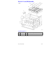
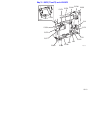
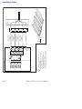
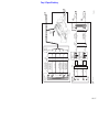
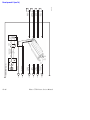
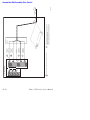
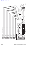
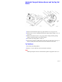
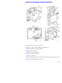
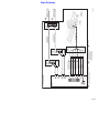
Image Processor Board and Rear Panel Host
Interface
The components on the image processor board are illustrated in the following figure.
6
2
1
4
5
7
8
3
1. RAM (SODIMM)
6. Processor Fan
2. RAM (SODIMM)
7. NVRAM
3. USB Connector
8. Ethernet Connector
7750-170
4. Health LEDs
5. Hard Drive
General Information
1-7
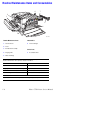
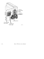
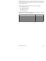
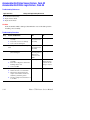
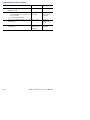
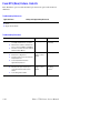
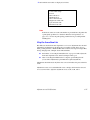
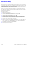
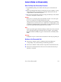
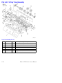
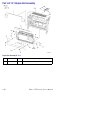
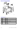
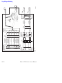
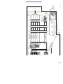
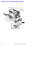
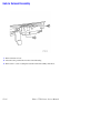
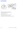
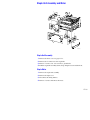
Routine Maintenance Items and Consumables
6
7
2
1
3
4
5
7750-449
Routine Maintenance Items
Consumables
1. Transfer Roller
6. Toner Cartridges
2. Fuser
3. Belt Cleaner Assembly
Service Parts
4. Imaging Units
7. Accumulator Belt
5. Waste Cartridge
Consumable capacity is based on 5% per color on A4/Letter paper.
Routine Maintenance Item capacity is based on A4 @ 5%.
Routine Maintenance:
Consumables:
Transfer Roller
100,000
Cyan Toner
22,000
Imaging Units
30,000 A4 images
Magenta Toner
22,000
Fuser Unit
60,000
Yellow Toner
22,000
Waste Cartridge
27,000
Black Toner
32,000
Service Parts:
Accumulator Belt
1-8
Lifetime (480,000 - coverage independent)
Phaser 7750 Printer Service Manual
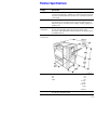
Printer Specifications
Physical Dimensions and Clearances
Print Engine Dimensions
Value
Height:
493 mm (19.4 in.)
Width:
644 mm (25.4 in.)
Depth:
715 mm (28.15 in.)
Weight:
91 kg (200 lbs.)
2500-Sheet High-Capacity
Feeder Dimensions
Value
Height:
364 mm (14.3 in.)
Width:
644 mm (25.4 in.)
Depth:
682 mm (26.9 in.)
Weight:
40 kg (88 lbs.)
1500-Sheet Lower Tray Deck
Dimensions
Value
Height:
364 mm (14.3 in.)
Width:
644 mm (25.4 in.)
Depth:
682 mm (26.9 in.)
Weight:
30 kg (66 lbs.)
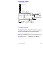
Clearances - For the optional finisher clearances, see "Phaser 7750 Finisher" on page 11-1
5.0 cm
(1.96 in.)
10.0 cm
(4.0 in.)
36.8 cm
(14.5 in.)
160.4 cm
(63.1 in.)
42.5 cm
(16.7 in.)
106.1 cm
(41.8 in.)
7750-224
General Information
1-9
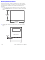
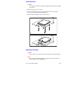
Mounting Surface Specification
These specifications apply to any Phaser 7750 printer used as a table-top printer,
without a lower tray assembly or cart. There are 4 feet on the bottom of the printer.
The right hand side of the printer is more susceptible to problems due to foot
placement.
1. In order to function properly, the printer must be located on a surface with the
following minimum dimensions. All 4 feet must rest squarely on the mounting
surface.
485 mm Min
19.10 in
530 mm Min
20.87 in
7750-339
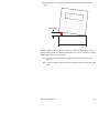
2. Mounting surface flatness must be within the range shown in the following
figure.
Right Hand Side
5mm Max
7750-340
1-10
Phaser 7750 Printer Service Manual
3. The printer must not be tipped or tilted more than is shown in the following
figure.
5mm Max
7750-341
Failure to adhere to these mounting specifications will void all guarantees of print
quality and/or performance. Known problems that can occur as a result of exceeding
the mounting surface specifications are:
■
Color-to-Color mis-registration, primarily in the horizontal (laser scan)
direction.
■
A smear or band of toner approximately 40 mm from the trailing edge of the
print.
General Information
1-11
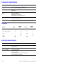
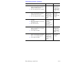
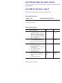
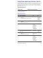
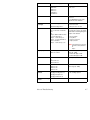
Functional Specifications
Characteristic
Specification
Printing process
The Phaser 7750 printer uses lasers with an electrophotographic
four-color (CMYK) single pass print process.
Color medium
Four color toner cartridges: Cyan, Yellow, Magenta, and Black
EAHG Toner
Resolution / Print
Modes
Standard: 1200 x 600 dpi
OHP: 1200 x 600 dpi
Enhanced: 1200 x 1200 dpi
Photo: 1200 x 1200 x 1-bit under color
First Page-Out (Letter/
A4)
< 11 seconds color
<10 seconds monochrome
Warm-up time
Warm up time to Ready from power on or ENERGY STAR, 40 seconds.
First page out from Ready, 7.4 seconds mono, 6.7 seconds color.
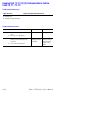
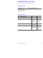
Print Speeds
Speeds
Ltr/A4
Ltr/A4
Duplex
Tab/A3
Tab/A3
Duplex
Standard 1200 x 600 dpi
35
28
17
13/13
Photo 1200 x 1200 dpi
22
18
11
8
OHP
8
N/A
N/A
N/A
Card
11
N/A
9
N/A
Labels
N/A
N/A
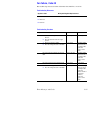
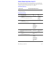
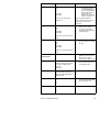
Electrical Specifications
Characteristic
Specification
Primary line voltages
115/127 VAC 10 A
200/240 VAC 5 A
Frequency range
50/60 Hz (+/- 3 Hz)
Power consumption
Power saver: 45 watts
Standby: 130 watts
Ready: 220 watts
Continuous Printing: 220 to 600 watts average
Peak (warming up): 1100 watts
1-12
Phaser 7750 Printer Service Manual
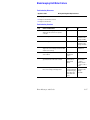
Environmental Specifications
Characteristic
Specification
Temperature:
Operating: 10 to 32o C
Storage: -20 to 50o C
Humidity
Normal operating: 10 to 85% relative humidity
Optimum operating: 25 - 75%
Altitude
0 to 2500 m (8000 ft.)
Acoustic Noise
Idle: 29 dB(A)
Printing: 52 - 53 dB(A)
Media and Tray Specifications
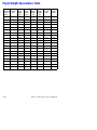
For information on approved Phaser 7750 media and paper types, print the “Paper
Tips Page” from the printer’s front panel.
General Information
1-13
1-14
Phaser 7750 Printer Service Manual
Theory of
Operation
In this chapter...
■
Summary of the Phaser 7750 Print Process
■
Paper Path of the Printer
■
EAHG Toner
■
Technology Overview
■
ROS and Regicon Technology Overview
■
RegiCon Overview
■
Sensors
Chapter
2
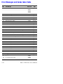
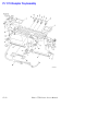
Summary of the Phaser 7750 Print Process
The Phaser 7750 Color Laser Printer is a ‘full-color laser printer’, that utilizes
electrophotographic recording principles to place a full color image onto the print
media. The system contains a drum and developing unit for each color (yellow,
magenta, cyan and black (YMCK), and places the toner image of each color onto
print media via an intermediate transfer belt, producing full-color prints.
A summary description of the printing process is presented in the following steps:
1. Charging: The imaging unit charge roller is negatively charged by the HighVoltage Power Supply (HVPS) and is kept in contact with the drum surface to
provide a uniform negative charge on the drum as it rotates at a constant speed.
This occurs simultaneously for YMCK.
2. Exposure: The laser unit emits laser beams modulated by image data from the
Image Processor board. The laser beams are directed onto the drum surface
through a system of mirrors and lenses. A rotating polygonal mirror causes the
laser beams to scan the drum surface from end to end (axially) as it rotates. The
beams are turned on to print a pixel and off when no printing is required. The
negative charge on the drum surface is reduced at each point where the energized
laser beam strikes, to form an electrostatic latent image on the drum surface. This
process is performed simultaneously for YMCK.
3. Development: Toner is electrostatically attracted to the invisible latent image
on the drum surface to form the visible image on the drum. Toner is fed into the
developer using the agitator and auger. The toner and the carrier in the developer
form a layer on the magnet roller in the developer. The magnet roller turns
against the surface of the drum and is kept at a constant negative potential. At
areas on the drum surface where the negative charge has not been reduced by the
laser light, potential between the drum and the toner particles is lower than that
between the magnet roller and the toner particles. At areas where the drum
charge has been reduced, the potential between the particles and drum is higher
than between the magnet roller and toner particles are attracted to the drum. A
thin semiconductive sleeve on the magnet roller is vibrated by an AC voltage to
encourage migration of the toner particles to the drum. When the toner particles
attach to the drum, the negative charge of the particles reduces drum potential at
that point, thus reducing the attraction of additional toner particles. This process
is performed simultaneously for YMCK.
4. Primary Transfer (Drum --> Accumulator Belt): All four toner images,
formed on the individual drum surfaces, are transferred to the accumulator belt
sequentially to create a complete, 4-color toner image. The accumulator belt is
conductive and receives a high positive charge from the HVPS. The negatively
charged toner image on each drum surface is attracted by the high positive
potential and transfers to the accumulator belt. During this transfer, the remaining
negative charge on the drum is neutralized by the high positive charge on the belt.
5. Cleaning: The drum cleaner consists of a blade and a brush in contact with the
drum after the point where the toner is transferred to the accumulator belt. The
cleaner brush receives a high positive voltage from the HVPS allowing it to
electrically attract any toner particles remaining on the drum. Toner remaining on
the accumulator belt after the image transfer to the print media is removed by the
belt cleaner assembly and transferred to the waste bin.
2-2
Phaser 7750 Printer Service Manual
6. Secondary Transfer: The image on the accumulator belt is transferred onto
the print media using the voltage supplied by the transfer roller. The conductive
transfer roller receives a high positive voltage from the HVPS that puts it at a
higher potential than the accumulator belt. Since the transfer roller is located
behind the print media, the 4-color toner image is attracted to the lower potential
and transfers to the surface of the print media.
7. Cleaning: The accumulator belt cleaner consists of a cleaner blade in contact
with the accumulator belt surface after the point where the toner is transferred to
the print media. Toner remaining on the accumulator belt after the image transfer
to the print media is stored in the waste cartridge.
8. Fixing: The finished toner image is unstable and easily smeared. To fuse the
image, the print media goes through the fuser assembly where it passes between a
pressure belt and the heat roller. The toner is fused onto the print media by the
combination of heat and pressure.
Theory of Operation
2-3
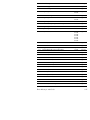
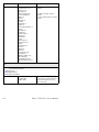
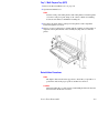
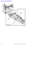
Paper Path of the Printer
The Phaser 7750 printer has a C-shaped paper-handling path. The design helps it
achieve high production outputs. The paper paths available for the paper exiting the
fuser are:
■
Straight to the Output Tray in the Top Cover (facedown).
■
Straight to the optional Finisher.
■
Paper can be inverted for 2-sided printing.
7750-125
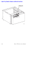
Trays 1-5
The paper trays consist of four main trays and one Multi-Purpose Tray on the side of
the printer. Tray 1 (MPT) is located on the left side of the machine and allows feeding
of specialty media stock, envelopes, and custom size paper. On the GX configuration,
Trays 2, 3, 4, and 5 are identical and can be interchanged. On the DXF configuration
(not shown), Trays 2 and 3 are identical and can be interchanged. Trays 4 and 5 are
the high-capacity feeder paper trays.
2-4
Phaser 7750 Printer Service Manual
Paper Size Sensing
Trays 2 through 5 automatically sense the standard size media loaded in the printer by
using the paper size sensors mounted on the back inside of the printer. When paper is
loaded in the tray and the paper guides are adjusted, the levers on the bottom of the
trays change the size sensor actuator locations.
Actuating different combinations of the paper size sensors produces different
combinations of high and low signals, which tell the printer logic what size of paper
to display on the front panel, once the tray has been re-inserted into the printer.
Tray presence is also detected by the paper size sensor. Any actuation of the paper
size sensor signals the tray is present.
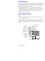
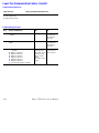
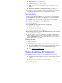
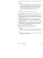
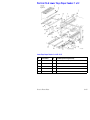
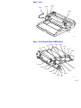
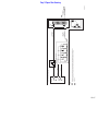
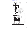
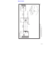
Paper Feeding and Sensing
Note
The tray feed / lift motor is a dual purpose motor, providing both the paper feed
and tray lift drive functions.
When the control logic calls for paper feed, the pick roller moves a sheet of paper to
the nip of the feed rollers and retard rollers. The rollers feed the paper to the takeaway
roller in the vertical transport where it is stopped and registered at the registration
roller.
Registration Roll
Registration
Sensor
Tray 2 Feed
Out Sensor
Takeaway Roll 2
Feed Roller
Retard Roller
Pick Roll
Takeaway
Sensor
Tray 4 Feed
Out Sensor
Tray 5 Feed
Out Sensor
Tray 2-5 Paper Path
7750-456
Theory of Operation
2-5
Stack Height Sensing
The pick roller feeds the paper to the paper path. As paper continues to feed, the stack
height drops. When it reaches a certain level an actuator unblocks the stack height
sensor. The control logic then stops paper feed and raises the paper tray. This causes
the actuator flag to block the stack height sensor again which signals the control logic
to resume feeding paper. The stack height sensing operates the same way for Trays 2,
3, 4, and 5.
Paper Present Sensing
When the last sheet is fed from any of the four main trays, the no paper sensor
actuator drops into an opening in the paper tray and unblocks the no paper sensor.
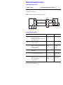
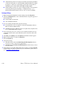
Tray 1 (MPT) Loading and Feeding
Tray 1
Solenoid
Tray 1 Feed Roll
Tray 1 No Paper
Sensor
Tray 1 Takeaway
Roll
Registration
Clutch
Registration
Roll
Registration
Sensor
OHP Sensor
Takeaway
Clutch
7750-457
When media is placed in Tray 1, the lead edge deactuates the Tray 1 no paper sensor.
The sensor signals the control logic that paper is present. When the last sheet of paper
is fed from the tray the actuator drops through the opening of the tray and activates
the sensor.
When the user prints from Tray 1, the control logic supplies mechanical drive to the
feed roller and nudger. When the control logic calls for paper feed, it sends a feed
signal to momentarily energize the Tray 1 solenoid causing the feed roller to pivot
down. When the pick roller contacts the paper, a sheet is fed into the nip between the
feed roll and the takeaway roll.
2-6
Phaser 7750 Printer Service Manual
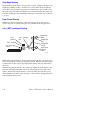
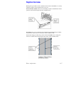
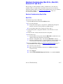
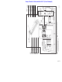
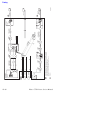
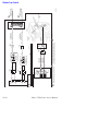
2-Sided Printing
Inverter Reverse
Clutch
Inverter Forward
Clutch
Exit Roll
Full Paper
Stack Sensor
Face Down
Tray
Fuser Exit
Switch
Exit Gate
Fuser Assy
Fuser
Exit Roll
FUSER
ACCUMULATOR BELT
Regi. Roll
Regi. Clutch
Registration
Regi.
Sensor
MPT
Main Motor
Duplex Motor
7750-450
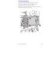
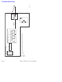
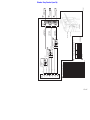
Paper leaving the fuser can be directed to the top output tray or the finisher. If 2-sided
(duplex) printing has been selected, paper can be directed through the inverter
transport and into the duplex transport. The duplex paper path reverses the direction
of paper travel and the duplex gates direct the paper through the inverter and into the
duplex transport. An image can then be placed on the second side of the media.
Theory of Operation
2-7
Fuser
The fuser receives its drive from the main motor. After the toner images are applied to
the paper, the paper is then passed through the fuser. The fuser belt is pressed against
the heat roller to melt the toner and bond it to the paper.
The fuser belt is always spring loaded against the heat roller, but can be released for
jam clearance. The flexibility of the belt (versus a pressure roller) provides a longer
contact time and a larger area of contact with the heat roller, thereby providing better
fusing.
Fuser Life Expectancy
The life expectancy of the fuser is 60,000 letter/A4 size pages. Several factors can
reduce the life of the fuser:
■
Greater than 5% coverage
■
Paper use larger than letter size
■
Printing on heavy media
■
Printing short-edge feed
■
Printing on transparencies or specialty media
Three fuses on the fuse board in the fuser assembly are used in conjunction with a
PostScript algorithm to determine the life used. Fuses are blown in the reverse order
than they were on the Phaser 7700 (3,2,1 instead of 1,2,3). Fuse #3 is blown after 100
prints are made. Fuse #2 is blown at 50% of life and fuse #1 is blown at 99% of life
used.
If fusers are swapped between printers and don’t have the exact same configuration of
blown and closed fuses the printer will make a fuser life assumption based on which
fuses are closed and then set the fuser life using that assumption after 100 prints are
run. All fuses closed, new fuser. Fuse 3 open, fuse 2 and 1 closed, life will be set at
25% used. Fuse 3 and 2 open fuse 1 closed, life will be set at 75% used. All fuses
open, life is set at 99% used.
2-8
Phaser 7750 Printer Service Manual
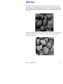
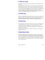
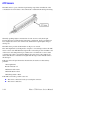
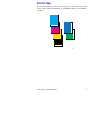
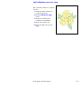
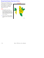
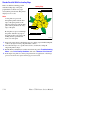
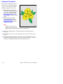
EAHG Toner
EA (Emulsion Aggreate High Gloss) toner is a relatively new type of toner with
particles that are more spherical and uniform in size. This toner will be used for all
Phaser 7750 Printer applications. The image below shows the EA toner particles. The
small bumps are particles of additives that produce some of the characteristics of the
new toner.
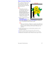
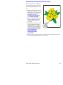
The image below shows some DC12 conventional toner. Like the EA toner, the small
bumps on the outside of the toner particles are additives that are used to provide
specific characteristics.
Theory of Operation
2-9
Technology Overview
Standby Power
There are two types of standby power in this machine: switched AC and switched
DC. Switched power requires that both the circuit breaker and the printer’s main
power switch be in the ON position.
■
Switched AC Power - This is the control signal whose power off transition is
delayed to allow the second bias transfer roller to retract.
■
Switched DC Power - Switched AC power from the AC Drive PWB goes to
the low voltage power supplies for the printer. Whenever switched AC
power is provided to the three low voltage power supplies, their output DC
voltages are activated by a 5 VDC signal.
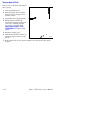
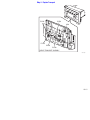
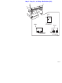
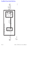
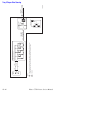
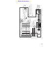
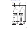
Machine Run Control and NVRAM
Machine control centers on the following:
■
Engine Control Board
■
Image Processor Board
Machine parameters are held by non-volatile memory located in two places:
■
Image Processor NVRAM
■
Engine NVRAM
Image Processor Board
Engine Control Board
7750-458
2-10
Phaser 7750 Printer Service Manual
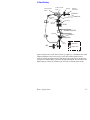
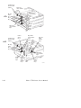
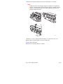
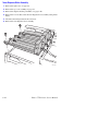
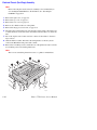
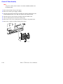
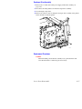
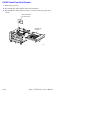
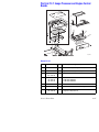
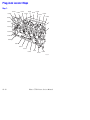
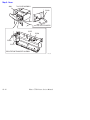
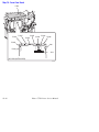
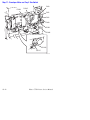
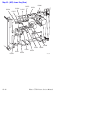
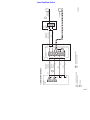
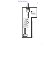
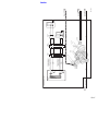
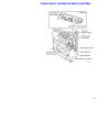
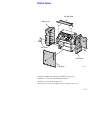
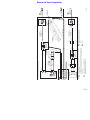
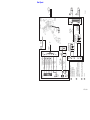
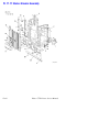
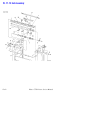
Drive Power
The Drive Power subsystem includes five motors and their driven assemblies.
■
Main Motor - The main motor provides the drive for paper feed, black developer
housing, and the fuser. The main motor gets 24 VDC power from the +24 Volt
power supply by way of the interface board. The motor enable and speed control
signals come from the microprocessor on the engine control via the interface
board.
■
Accumulator Belt Motor - The accumulator belt motor turns the drive roller for
the accumulator belt and the accumulator belt cleaner auger.
■
Transfer Roller Motor - Engages and retracts the transfer roller.
■
Developer Motor - The developer motor provides the drive for the C, Y, and M
developers.
Theory of Operation
2-11
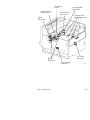
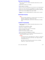
■
Imaging Unit Motors - There are two imaging unit motors providing drive to the
four imaging units: one drives the Y, M, and C drums, and the other drives the K
(black) drum. Like the main motor, the drum motors get 5 and 24 volt DC power
from 5 and 24 volt power supplies via the interface board. The motors are
enabled and the speed is controlled by the engine control board.
Main
drive
assy
Black
Imaging Unit
motor (K)
(hidden)
Developer
drive assy
Imaging Unit
drive assy
Accumulator
belt drive assy
7750-451
2-12
Phaser 7750 Printer Service Manual
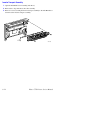
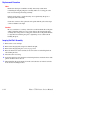
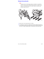
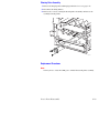
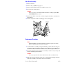
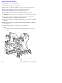
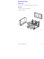
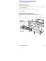
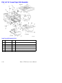
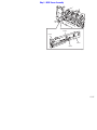
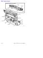
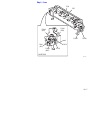
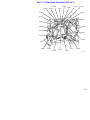
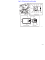
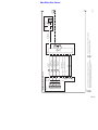
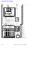
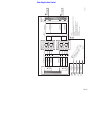
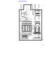
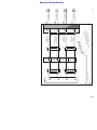
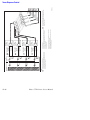
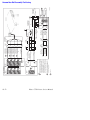
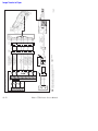
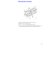
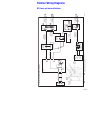
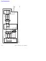
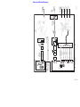
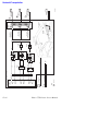
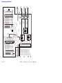
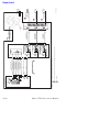
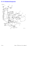
System Power Supplies
The System Power Supplies consist of: the T1, T2, and T3 HVPS, the 24 Volt LVPS,
3.3 VDC LVPS, and the (2) 5VDC LVPS.
Engine Control Interface Board
High Voltage Power Supply/ T1 Board
High Voltage Power Supply/ T3 Board
High Voltage Power Supply/ T2 Board
GFI
AC Drive Board
Noise Filter Board
Theory of Operation
S7700-317
2-13
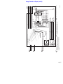
24 V Low
Voltage Power
Supply
24 V Low
Voltage Power
Supply Fan
AC Power Chassis
3.3 V Low Voltage
Power Supply
2-14
5 V Low Voltage
Power Supply
7750-448
Phaser 7750 Printer Service Manual
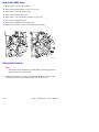
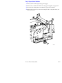
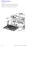
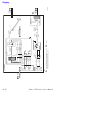
ROS and Regicon Technology Overview
The locations of the ROS and the ROS shutter solenoid are shown in the following
figure.
■
There are four ROS shutters (not shown).
■
The ROS module is field replaceable and contains four laser diodes, one
polygon motor/mirror, and several lenses and mirrors.
■
The ROS module “reflects” the four laser beams so that they strike the
Imaging Units correctly.
■
The ROS module contains four mirrors that can be adjusted for skew using
RegiCon. This adjustment MUST be made when the ROS is replaced.
■
NEVER remove the cover from a ROS module for ANY reason contamination will result.
Write Black Process
The Phaser 7750 Printer uses a “black writing” process for exposing the imaging
units.
In the write black process, the image areas are discharged, or exposed. Because the
image area is normally much smaller than the background area, the Write Black
approach extends the life of the laser diode.
In the Write Black process, the negative toner particles are attracted to the more
positive image areas on the photoreceptor and repelled by the higher negatively
charged background areas. A negative developer bias voltage assures good
development of the image areas.
Theory of Operation
2-15
In the Write Black process for the Phaser 7750 printer, the four individual images, one
in each color, are transferred to the surface of the accumulator belt.The second
transfer roller puts a positive charge on the copy paper. Then the four-color image is
transferred to the sheet of paper in one pass. The positive charge attracts the negative
toner particles from the accumulator belt to the copy paper.
The image data is processed through the image processor board and is then routed to
the engine control board. On the image processor board, the process of screen
generation is conducted. In this process, the incoming image data is arranged in a
screen pattern before being sent to the ROS (Laser).
The engine control board is the ROS driver board. In other words, it is the last
location in the imaging path before the image data becomes optical information in the
form of modulated laser beams.
In the case of the Phaser 7750 printer, the engine control board sequentially passes
data that comprises the 4 different color planes to the Laser Diodes in the ROS.
The color planes are digital at this time, that is, they are a stream of 1’s and 0’s. The
digital information is applied to the ROS control circuit to turn the laser diodes on and
off. (A 0 turns the laser on and a 1 turns it off.) Using this technique, the digital levels
that make up the image data are modulated onto the laser beams.
As each of the four laser diodes scans the surface of the drum (in the YMCK
sequence), the image data is reflected and collimated within the ROS and is finally
reflected out to each imaging unit where the charged photoreceptor is exposed by the
laser. As the laser beam scans across the photoreceptor, a latent image is created on
the surface of the drum. As the imaging unit turns, it acquires the latent image from
the ROS, and toner from the developer housing.
2-16
Phaser 7750 Printer Service Manual
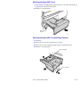
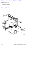
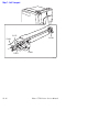
RegiCon Overview
The RegiCon procedure is used to ensure that the four lasers in the ROS are correctly
aligned to provide correct registration for each color.
The Mark On Belt (MOB) sensors are used in this procedure to determine the relative
position of chevrons developed onto the accumulator belt.
The MOB sensors are located below the accumulator belt. The RegiCon procedures,
read chevrons on the front, rear, and center of the accumulator belt.
In the Center Setup procedure, the position of the front MOB sensor is changed to
allow it to read the chevrons developed on the center of the accumulator belt.
Theory of Operation
2-17
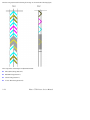
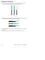
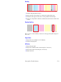
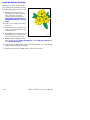
The chevron patterns used for the RegiCon setup are shown in the following figure.
The components of the RegiCon adjustment include:
■
Skew (Fine) Setup (Pattern 1)
■
IN/OUT Setup (Pattern 1)
■
Center Setup (Pattern 1)
■
Coarse Skew Setup (Pattern 2)
2-18
Phaser 7750 Printer Service Manual
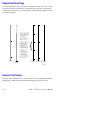
#1 Skew (Fine) Setup
The Skew (Fine) Setup is performed to ensure that images on the accumulator belt are
not skewed.
To complete this part of the procedure, a series of chevron images are developed on
the belt, using all four colors. (Pattern 1 on the previous figure shows the chevron
patterns). The chevron patterns are developed on the belt on the front and rear edges
of the accumulator belt. The MOB sensors read them, and the horizontal and vertical
position of the marks are calculated. If the marks are found to be skewed, the
diagnostic tool indicates the number of clicks and direction that the adjustment screws
on the front of the ROS should be turned to correct the skew.
#2 IN/OUT Setup
Like Skew, the IN/OUT Setup procedure uses the chevrons that are developed on the
front and rear edges of the accumulator belt. (Pattern 1 on the previous figures shows
the chevron patterns). During this procedure, logic automatically performs a
magnification adjustment so that the scan lines are the same length for all four colors.
#3 Center Setup
The Center Setup procedure determines if the chevrons developed on the center of the
accumulator belt are in the correct location relative to the front and rear chevrons.
To perform the procedure, the MOB sensor is positioned to the center of the
accumulator belt and the chevrons are developed. (Pattern 1 on the previous figures
shows the chevron patterns).
In this procedure, the midpoints of the scan lines for all four colors are aligned for
magnification balance.
#4 Skew (Rough) Setup
The Skew (Rough) Setup is used only when skew is outside of the measurement
parameters of Skew (Fine) Setup. It should be run in situations when the registration
is so far out of specification as to be immeasurable by the Skew (Fine) Setup routine.
In this routine, Pattern 2 (from the figure showing the chevron patterns) is developed
and the registration of the images is calculated. If necessary, the skew of the image
can be adjusted manually.
Theory of Operation
2-19
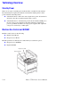
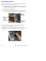
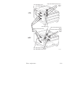
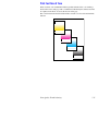
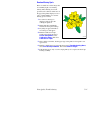
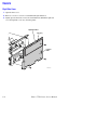
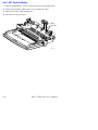
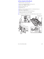
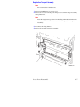
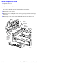
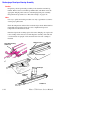
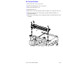
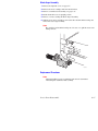
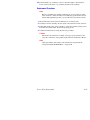
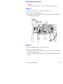
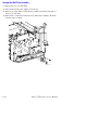
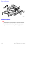
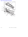
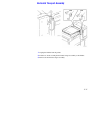
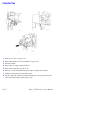
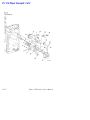
View the RegiCon Patterns
It is possible to see the patterns that are developed on the accumulator belt for the
RegiCon calibration by performing the following steps:
■
If there is a finisher present on the machine, slide it to the right so that the
right hand access door to the accumulator belt can be opened. Open the
access door and activate the interlock.
■
Power down the Phaser 7750 printer.
■
Open the front door and release the accumulator belt by releasing the latch
assembly and pulling down the lift lever as shown in the figure below.
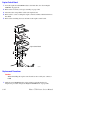
■
Lift the accumulator belt assembly release and pull the accumulator belt
assembly out until the stand plate is accessible.
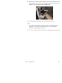
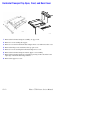
■
Remove two screws that hold the stand plate on the front and rear of the
accumulator belt assembly. Lift the stand plate as shown in the figure below, and
remove it.
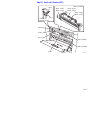
2-20
Phaser 7750 Printer Service Manual
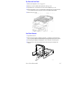
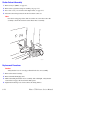
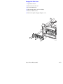
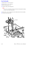
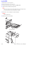
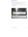
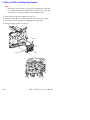
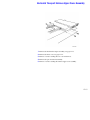
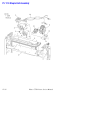
■
Reinsert the accumulator belt assembly into the Phaser 7750 printer without
the Stand Plate. The area that was covered by the Stand Plate will be the area
in which you see the images on the accumulator belt.
■
With the right hand door interlock activated, turn the printer on.
Note
For machines with finishers, unplug the finisher from the Phaser 7750
printer prior to powering up. It will be necessary to have the finisher
undocked to view the images on the belt.
■
As soon as the chevrons are visible, deactivate the right hand door interlock.
Theory of Operation
2-21
Sensors
Looking at the imaging path illustration below, note that there are two kinds of
sensors that play an important role in the control of image quality for the printer.
Output
Fuser
Internal
Test
Patterns
I/P Board
Toner
1st
Cartridge
ADC
(4)
Sensor Transfer
Roller
2nd
Transfer
Roller
Engine Board
Imaging Unit
ROS
Developer Housing &
ATC Sensors
Charge
Rolls
Network
cable
7750-452
Transfer Roller Sensor
Tray 1 Take Away Sensor
Transparency Sensor
Registration Sensor - on left door optic
Paper On Belt Sensor
MPT No Paper Sensor
Tray 1 No Paper Sensor/Level Sensor
MPT Paper Size Sensor
2-22
7750-460
Phaser 7750 Printer Service Manual
Environment
Sensor
Automatic Density
Control Sensor
Accumulator Belt
Home Sensor
Duplex
Wait Sensor
Automatic Toner
Concentration Sensor
K, C, M, Y
Tray 1 Paper
Size Sensor
Mark On
Belt Sensor
Waste Cartridge
Full Sensor
Theory of Operation
Accumulator Belt
Edge Sensor
7750-461
2-23
ATC Sensors
The ATC sensor is a part of the developer housing. It provides an indication of the
concentration of toner relative to the carrier beads contained in the developer housing.
Generally speaking, higher concentrations of toner are more easily developed,
because they have less triboelectric bond to the carrier beads. Lower concentrations
have a higher attraction to the carrier beads, and therefore require higher charge to
develop out.
The ATC sensor provides its information to the process controls.
The "Tone Up/Down" test in diagnostics compares a corrected target value to the ATC
sensor value on each individual developer. If the corrected target value is within +/-30
of the sensor value then printer logic assumes toner concentration is correct. If the
corrected target value is greater than 30 units above the sensor value, printer logic
detects that the toner concentration is lighter than the target value and adds toner to
the developer.
If the test values all equal the results shown below, the test has not detected any
problems.
<Tone Up/Down>
Result = 0 Status = 0
ATC Sensor Fail = None
ATC Limit Warn = None
ATC Change Warn = None
If the ATC sensor fails, possible causes are:
■
The sensor connection is bad, try reseating the connector.
■
The sensor is defective.
2-24
Phaser 7750 Printer Service Manual
■
There is a developer problem either with the housing or the amount of beads
in the developer.
Tone Up/Down Messages
Front Panel Message
Typical Values
[CMYK] Sens Warn
0
Pages = XX
Number of pages since last check
ATC Control = XXX
565
ATC Corr = XXX
604-606
Ave ATC = XXX
593-615
ATC Vol = XXX
320-428
ADC Sensor
The sensor in this figure is the Automatic Density Control (ADC) sensor. It is located
on the MOB Sensor Assembly.
To control image quality, this sensor looks at patches that are developed onto the
accumulator belt at various times.
Data from the ADC sensor is used to:
■
Adjust the intensity of each laser in the ROS.
■
Set the look up table for Tone Reproduction Curve (TRC).
■
Determine amount of toner to add to developer (triggered by ATC sensor).
Theory of Operation
2-25
■
Determine toner cartridge empty (triggered by ATC sensor).
2 patches per color are printed and ADC control is initiated at:
■
Power-on, return from ENERGY STAR, after interlock close.
■
End of each job.
■
Within a job (every 80 pages at full speed, every 40 pages at half
speed.
During normal operation, the ADC sensor reads the density of patches on the
accumulator belt to ensure that the machine is providing its best output. Based on the
readings of these patches, the concentration of toner in the developer housings can be
changed or laser power adjusted.
For example, if the customer ran a large number of images that contained a high
concentration of yellow, the yellow developer housing would become somewhat
depleted of yellow toner.
The machine would first notice this depletion as a patch on the accumulator belt that
is less dense than the specifications allow, and due to the ATC Sensor’s indication.
In this situation, the machine would automatically tone up, adding more toner to the
developer housing. The higher concentration of toner in the housing would then allow
more toner to be developed out to the accumulator belt, and the patches would then
start to become more dense. In this way, the system corrects itself when density
becomes too low.
ADC Output Check
The ADC Sensor Assembly consists of 3 sensors that read values off the CMYK test
patches. The "regular reflection", "diffusion" and "offset" sensors provide readings to
the printer logic to determine if density is correct.
"ADC Output Check", in diagnostic mode, compares a target value in logic to the
value seen by the individual sensors. If the value seen by the sensors is between -20
and +20 of the target value the printer density is correct.
If the test values shown below, displayed on the front panel, all equal zero, the test has
detected no problems.
■
Result = 0
■
Stop Status = 0
■
ADC Sensor Fail = 0
■
ADC Shutter Fail = 0
If the "ADC Sensor Fail" test detects a problem, check the connector to the sensor. If
the connector is OK, replace the sensor.
2-26
Phaser 7750 Printer Service Manual
If the ADC Shutter Fail test detects a problem, check the connector and the shutter for
a binding or out of position condition. If these actions do not resolve the problem,
replace the MOB Assembly.
If the following values all equal none, the test has detected no problems
■
LD Illum Warn = None
■
ADC Patch Fail = None
■
VBCR Warn = None
■
V Bias Warn = None
If Ave RADC Trans is within +/-20 of RADC Target, then printer logic assumes the
density is correct. Values on the front panel are:
Front Panel Message
Typical Values
[YMCK] RADC Target = [XXX]
[YMC] 375-394 [K] 460
Ave RADC Trans = [within +/-20 of RADC Target]
[YMC] 369-393 [K] 467
Ideal LD Ill = [XXX]
[YMC] 335-361 [K] 394
V Bias = [XXX]
887
V BCR = 0
0
Theory of Operation
2-27
Lower Tray Feeders Sensor and Board Locations
LTD Board (3T)
HCF Board (TT)
7750-459
2-28
Phaser 7750 Printer Service Manual
Tray 5 Take-Away Sensor
Tray 4 Take-Away Sensor
Paper-Size Switch Assembly -Tray 3
-Tray 4
-Tray 5
LTD
3
4
5
Take-Away Sensor
No-Paper Sensor/Level Sensor
Tray 3
Tray 4
Tray 5
Paper-Size Switch Assembly
-Tray 3
Paper-Size Switch Assembly
-Tray 4
-Tray 5
3
HCF
5
4
Tray 4 Take-Away Sensor
Tray 5 Take-Away Sensor
Theory of Operation
7750-462
2-29
Left hand cover
interlock switch
actuator
LTD
Paper feed
sensor actuator
tray 4
Paper detect
sensor actuator
tray 3
tray 4
tray 5
One way
clutch
tray 3
tray 4
tray 5
Friction
clutch
tray 3
tray 4
tray 5
Paper feed
sensor actuator
tray 5
HCF
Left hand cover
interlock switch
actuator
Friction
clutch
tray 3
Paper detect
sensor actuator
tray 3
tray 4
Paper size
switch
actuator
tray 5
One way
clutch
tray 5
One way
clutch
tray 3
tray 4
Paper detect
sensor actuator
tray 5
Friction
clutch
tray 4
2-30
Paper size
switch
actuator
tray 4
Friction
clutch
tray 5
7750-463
Phaser 7750 Printer Service Manual
Error Messages
and Codes
In this chapter...
■
Introduction
■
Overview for Troubleshooting Error Codes
■
System Startup and POST
■
Error Messages and Codes Index Table
■
Error Messages and Codes Procedures
Chapter
3
Introduction
This section covers troubleshooting procedures for the Phaser 7750 printer front panel
error messages and codes. Only jams and fatal errors will produce an associated
numeric code. Error messages and codes are generally specific, making it important
that service personnel and users record errors when reporting problems with the
printer. Any code associated with an error message or jam can be viewed by pressing
the INFO button and scrolling to the bottom of the help text displayed on the front
panel.
Some procedures require performing service diagnostic tests to verify a specific
printer part is operating correctly. For information on Service Diagnostics and all
internal printer test functions, refer to "Service Diagnostics" on page 4-2.
To troubleshoot problems not associated with a front panel message or code, see
"General Troubleshooting" on page 4-1.
When an error first occurs, record the error message and code then cycle power to the
printer to see if the error recurs.
Always follow the safety measures detailed in the front of the manual when servicing
the printer, see “Service Safety Summary” on page vii.
Accessing the Printer’s Error History
If an error message or code is not visible on the front panel, and the printer is still
capable of printing, print one of the following pages from the printer’s front panel.
1. Engine Error History
a. Go to Troubleshooting ---> Service Tools --> Engine Error History
and press OK.
2. Jam History
a. Go to Troubleshooting ---> Service Tools --> Jam History and press
OK.
3. Service Usage Profile - For a definition of the numeric codes, see "Service
Usage Profile Status Codes" on page A-5.
a. Go to Troubleshooting ---> Service Tools --> Service Usage Profile
and press OK.
If the Printer is Unable to Print
If the printer is connected to a network and has a TCP/IP address, view the printer’s
web page using a web browser.
1. Open a web browser.
2. Enter the printer’s IP address as the URL.
3. Select the Troubleshoot link and the fault history displays.
3-2
Phaser 7750 Printer Service Manual
Service Checklist
This checklist is an overview of the path a service technician should take to service
the Phaser 7750 printer and it’s options.
Step 1: Identify the Problem:
1. Verify the problem reported by the customer.
2. Check for any error codes and write them down.
3. If the printer is capable of printing, print normal customer prints and service test prints to:
Make note of any print-quality problems in the test prints.
Make note of any mechanical or electrical abnormalities present.
■ Make note of any unusual noise or smell coming from the printer while printing.
4. Print a “Usage Profile”, if the printer is able to print and/or view the fault history under the
Service Tools Menu.
■
■
5. Verify the AC input power supply is within proper specifications by measuring the voltage at
the electric outlet while the printer is running.
Step 2: Inspect and Clean the Printer:
1. Switch OFF printer power and disconnect the AC power cord from the wall outlet.
2. Verify the power cord is free from damage and is connected properly.
3. Remove the Imaging Units and protect them from light.
4. Clean and inspect the printer interior and remove any foreign objects, dust or loose toner.
Note: Use only a Toner Type II Vacuum.
Do not use solvents or chemical cleaners.
Do not use any type of oil or lubricant on printer parts.
Do not use compressed air.
5. Clean all rubber rollers with a lint-free cloth, dampened slightly with cold water and mild
detergent.
6. Inspect the interior of the printer for damaged wires, loose connections, toner leakage, and
damaged or obviously worn parts.
Step 3: Find the Cause of the Problem:
1. Use the Error Messages and Codes troubleshooting procedures to find the cause of the
problem if an error code is reported.
2. Use Service Diagnostics to check printer parts.
3. Use the Wiring Diagrams and Plug/Jack Locator to locate test points and to take voltage
readings at various test points as instructed in the appropriate Troubleshooting procedure.
Step 4: Correct the Problem:
1. Use the Parts List to locate a part number.
2. Use the Removal and Replacement procedures to replace the part.
Step 5: Final Check:
1. Test the printer to be sure you have corrected the initial problem and there are no additional
problems present.
2. Perform RIP procedures.
Error Messages and Codes
3-3
Service RIP (Every Call) Procedures
These procedures are to be used for every service call.
1. Print an error log then diagnose and repair any problems as indicated.
2. Print a “Usage Profile” report, then diagnose and repair any problems as
indicated.
3. Check the cleanliness of the interior and exterior of the printer including fans.
Clean (dust or vacuum) these areas.
4. Check the versions of Engine and Postscript software. As appropriate, install the
latest version of software.
5. Inspect the fuser assembly and clean if necessary.
6. Inspect the MOB and ADC sensors, clean if necessary.
7. Inspect the accumulator belt home sensor, clean if necessary.
8. Clean feed rollers and exit rollers only when dust or debris is visible.
9. Clean the laser scanner windows.
10. Review the proper operation of the printer with the customer emphasizing
calibrate for paper, color calibration and setting the paper type correctly.
11. Have the customer make enough prints to verify any repairs that were done.
12. Review with the customer all work that was done.
3-4
Phaser 7750 Printer Service Manual
Overview for Troubleshooting Error Codes
Definition of the Chain-Link Codes
A chain-link is a numeric code represented as a pair with the chain first and the link
second. The “chain” is a 2-digit identifier representing a major or higher level subassembly. The “link” is a 3-digit identifier representing a specific failure mode.
The chain-link is used to identify or address a specific component within the printer.
The chain points to a counter or component assembly, and the link points to a specific
item in that assembly.
All chain-link codes and their respective definitions can be found in the Appendix
under "Missing Chain Link Codes Definitions" on page A-11.
Using the Troubleshooting Procedures
1. Each Step in a troubleshooting procedure instructs you to perform a certain
action or test. The steps are to be followed in the order given until the problem is
fixed or resolved.
2. The Actions and Questions box contains the procedures to perform and the
resulting actions you must follow to isolate the problem.
■
When a procedure instructs you to test a component using service
diagnostics, go to the "Service Diagnostic Tests Table" on page 4-3 for a
detailed description for testing printer components.
■
Troubleshooting procedures may ask you to take voltage readings or test for
continuity at certain test points within the printer. For detailed diagrams, see
"Wiring Diagrams" on page 10-1 for complete information on test point
locations and signal names.
3. The Actions are followed by a Question. If your response to the question is
“Yes”, then follow the instructions for the “Yes” reply. If your response to the
question is “No”, then follow the instructions for the “No” reply.
4. The problem will be isolated to an adjustment, calibration or a printer component
that needs replacement, see the following chapters for more information.
■
Chapter 6 "Adjustments and Calibrations" on page 6-1.
■
Chapter 8 "Service Parts Disassembly" on page 8-1 provides detailed steps
for removing and replacing all major parts of the printer.
■
Chapter 9, "Service Parts Lists" on page 9-1 details the location, quantity
and part number for all spared parts of the printer.
Error Messages and Codes
3-5
General Notes on Troubleshooting
1. Unless indicated otherwise, the instruction “turn ON printer power” means for
you to switch ON the printer power and let the printer proceed through POST to a
‘Ready’ condition.
2. When instructed to take resistance readings between “P/J 232 <=> P/J 210”
(without specified pin numbers), check all pins. See "Wiring Diagrams" on
page 10-1 for the location of all wiring harnesses and pins.
3. When you are instructed to take a voltage reading, the black probe (–) is
generally connected to a pin that is either RTN (Return) or SG (Signal Ground).
You can substitute any RTN pin or test point in the printer, and you can use FG
(frame ground) in place of any SG pin or test point.
4. Before measuring voltages, make sure the printer is switched ON, the imaging
units and the paper trays are in place, and the interlock switches are actuated,
unless a troubleshooting procedure instructs otherwise. Before measuring
continuity or resistance, make sure the printer is switch OFF.
5. All voltage values given in the troubleshooting procedures are approximate
values. The main purpose of voltage readings is to determine whether or not a
component is receiving the correct voltage value from the power supply and if
gating (a voltage drop) occurs during component actuation.
6. When a troubleshooting procedure instructs you to replace a non-spared
component and that component is part of a parent assembly, replace the entire
parent assembly.
3-6
Phaser 7750 Printer Service Manual
System Startup and POST
System Boot Sequence
1. When the main power switch is turned on, the ‘health’ LED on the image
processor board turns on immediately.
2. The boot loader checks for RAM present and functional. If not, it posts a very
large “RAM ERROR” on the front panel and blinks the LED 1/2 second on/off
continuously.
3. The boot Loader then runs POST diagnostics.
4. POST turns off the health LED.
5. POST checks the front panel.
6. If buttons have been pushed, the front panel displays “Processing Input”.
7. The front panel LED cycles: Green, Yellow, Red, and then off.
8. The front panel turns on, the LED turns Green, and the POST tests are run.
Power On Self Test (POST)
The following tests are performed when the printer is powered on, after the boot
loader runs, and before the operating system is loaded and initialized.
POST diagnostics are intended to provide a quick means of isolating a defective
subsystem associated with the image processor board and SDRAM. POST returns
control to the boot loader and the operating system is loaded. The operating system
then loads the imaging processing software. If POST detected any soft errors, a
message is printed in a red box on the start page. If POST detects any hard errors,
both the front panel and ‘health’ LED blink the error code pattern, see "POST Fault
Reporting LED Blink Patterns" on page 3-8.
POST Startup indications
■
At power-on the hardware default is to turn on the IP board ‘health’ LED.
■
The image processor board ‘health’ LED is turned off.
■
The front panel display is reset (addressable area becomes “gray”).
■
The Green LED turns on for 1/3 second.
■
The Yellow LED turns on for 1/3 second.
■
The Red LED turns on for 1/3 second.
■
The front panel LED is turned off.
■
The backlight is turned on (high intensity), with nominal contrast display.
■
The front panel display area is turned on, dark black for 1 second.
Error Messages and Codes
3-7
■
The front panel display is cleared.
■
The backlight is turned on with nominal intensity.
■
The POST Vn.nn message appears, and tests are quickly executed.
■
If any tests fail, the front panel screen freezes with the name of the test
displayed and the line posted is “Call Customer Service”.
■
After the POST tests have finished running, the Xerox ‘splash screen’ is
posted to the front panel and PostScript begins initialization.
POST Faults
There are two kinds of faults: soft and hard.
A soft fault is any fault that is discovered by POST, but does not prevent the operating
system from initializing and becoming available as a tool for troubleshooting. These
POST faults do not stop execution and are reported on the StartPage in a red box after
the system is running.
A hard fault is any fault discovered by POST that prevents the operating system from
initializing successfully. A hard fault prevents the system from further execution and
is halted with blinking LEDs (front panel and health LED). The test name of the test
that failed is displayed on the front panel.
Hard Fault Reporting Devices
■
The health LED flashes according to the fault code.
■
A Vx Works text string is printed out the serial port.
■
The front panel LED flashes in unison with the health LED.
■
The last fault message posted to the front panel is present.
Note
All soft faults are printed on the Startup Page.
POST Fault Reporting LED Blink Patterns
For faults identified as hard faults, the POST firmware causes the PS ‘health’ LED
and front panel LED, to blink in a particular pattern to identify the fault. There are
short and long blinks. A long blink is worth 5 and a short blink is worth 1. If a fault
blink pattern is flashed as long, long, short, short, this is fault code 5+5+1+1=12,
which indicates a failure in the CPU interrupt test.
The exception to the above pattern is a RAM test error. The RAM tests have a special
blink pattern and the front panel displays “RAM Error”. During power up the front
panel LED is on. If the RAM tests fail, the image processor board ‘health’ LED is
turned off, and the front panel LED is red. At 1/2-second intervals, the ‘health’ LED
and the front panel LED toggle continuously.
3-8
Phaser 7750 Printer Service Manual
POST Diagnostic Test Descriptions
Fault
Type
Test
SDRAM
Fault
Code
Hard
Description
1
This test fails if the boot loader finds no RAM present
or faulty RAM.
Boot loader posts the message “RAM error” to the
front panel and blinks the front panel LED and IP
Board health LED.
Local Bus/
Front Panel
Hard
2
Performed during the POST firmware initialization
phase.
If the front panel is unplugged, a hard fault is indicated
by the heath LED.
I/O ASIC
Hard
3
This test determines if the I/O chip is functioning
properly.
MEM
Hard
4
This test determines if the memory access function
works at selected addresses
Configuration
Chip
Hard
5
This test checks to see if the configuration chip is
present. If no chip is present the test fails and the front
panel message “Please Install configuration chip
displays.
EEPROM
Hard
10
This test checks addressing of the EEPROM.
Ethernet
Hard
11
This test checks the ethernet core.
CPU Interrupts
Hard
12
This test checks that each interrupt source to the CPU
is functioning.
USB
Hard
13
This test checks that the USB core is functioning
properly.
Real Time
Clock
Soft
14
RAM DIMM
Presence
Soft
15
Min RAM Limits
Soft
16
Checks that there is at least 128 MB installed and
ignores more than 512 MB.
Max RAM
Limits
Soft
17
Checks to ensure no more than 1 GB of RAM is
installed.
IDE Disk
Soft
20
Checks the disk controller core, and runs a
DIAGNOSE command on the hard drive.
CPU Fan
Hard
24
Checks hardware to see if a failure of the CPU cooling
fan has occurred.
Cage Fan
Hard
25
Checks hardware to see if a failure of the electronics
cooling fan has occurred.
Error Messages and Codes
The real time clock is tested.
This test examines bad or incompatible RAM DIMMs.
3-9
Error Messages and Codes Index Table
Code
Error Message
Chain-Link
Page
10
Laser Unit Failure
06-380
06-381
06-382
06-383
06-385
pg. 3-12
11
Laser Unit Polygon Motor Failure
06-372
pg. 3-12
12
Yellow ATC Sensor Failure
09-380
pg. 3-13
13
Magenta ATC Sensor Failure
09-381
pg. 3-13
14
Cyan ATC Sensor Failure
09-382
pg. 3-13
15
Black ATC Sensor Failure
09-383
pg. 3-15
20
Transfer Roller Contact Failure
09-342
pg. 3-17
21
Transfer Roller Retract Failure
09-343
pg. 3-17
1st BTR Contact Failure
09-348
pg. 3-18
1st BTR Retract Failure
09-349
pg. 3-18
30
Accumulator Belt Home Position Took Too Long
04-346
pg. 3-19
31
Accumulator Belt Home Position Failure
04-347
pg. 3-19
32
Accumulator Belt Edge Sensor Failure
04-348
pg. 3-22
33
Unexpected Accumulator Belt Home Sensor Signal
09-350
pg. 3-24
34
Accumulator Belt Drive Logic Failure
09-351
pg. 3-22
35
Fuser Main Lamp Failure
10-348
pg. 3-25
41
Install or Reseat Fuser
10-349
pg. 3-26
42
Fuser STS (front) Warm Time Failure
10-352
pg. 3-27
43
Fuser SSR1 On Time Failure
10-353
pg. 3-27
44
Fuser Sub Lamp Failure
10-350
pg. 3-29
45
Fuser STS (rear) Failure
10-351
pg. 3-30
46
Fuser STS (rear) Warm Time Failure
10-354
pg. 3-31
47
Fuser SSR2 On Time Failure
10-356
pg. 3-31
48
Fan Failure
10-398
pg. 3-33
60
Imaging Unit Motor Failure, Code 60
04-361
pg. 3-35
70
71
72
73
Imaging Unit 1...
2
3
4... Communication Failure
09-360
09-361
09-362
09-363
pg. 3-36
3-10
Phaser 7750 Printer Service Manual
Code
Error Message
Chain-Link
Page
Black Imaging Unit Motor Failure
04-363
pg. 3-37
78
Waste Cartridge Full Detection Sensor Failure
09-358
pg. 3-38
80
Engine Logic Board Failure
04-341
04-343
pg. 3-39
81
Controller To Engine Communication Failure
04-358
pg. 3-39
82
Engine Logic Board RAM/ROM Failure
04-340
04-342
pg. 3-39
83
Engine Logic Board NVRAM Failure
04-362
pg. 3-40
84
Controller to Engine Logic Board Timing Failure
04-371
pg. 3-40
85
Engine Logic Board Micro Pitch Failure
04-344
pg. 3-40
86
High-Voltage Power Supply Failure
04-345
pg. 3-40
87
Tray Lift Failure
07-281
07-282
07-283
07-284
07-291
07-292
07-397
pg. 3-41
88
Lower Tray Communication Failure
7-250
pg. 3-44
MPT Size Sensor Broken
7-274
pg. 3-43
The following Error Codes and Messages are associated with the optional Finisher:
111
Finisher Stapler Move Sensor On Failure
12-241
pg. 3-47
112
Finisher Stapler Move Sensor Off Failure
12-242
pg. 3-47
113
Finisher Stapler Failure
12-244
pg. 3-49
114
Finisher Front Tamper Home Sensor Failure
12-252
pg. 3-51
115
Finisher Rear Tamper Home Sensor Failure
12-253
pg. 3-52
116
Finisher Stacker Height Sensor Off Failure
12-254
pg. 3-53
117
Finisher Stacker Tray Failure
12-255
pg. 3-55
118
Finisher Stapler Front Corner Sensor On Failure
12-256
pg. 3-57
119
Finisher Stapler Front Corner Sensor Off Failure
12-257
pg. 3-57
120
Finisher Eject Clamp Home Sensor On Failure
12-260
pg. 3-58
121
Finisher Eject Clamp Home Sensor Off Failure
12-262
pg. 3-58
122
Finisher Decurler Failure
12-267
pg. 3-59
123
Finisher Set Clamp Failure
12-281
pg. 3-60
124
Finisher Communication Failure
12-350
pg. 3-61
125
Finisher Staple Mode Logic Failure
12-399
pg. 3-61
Error Messages and Codes
3-11
Error Messages and Codes Procedures
Laser Unit Failure, Code 10
Laser Unit Polygon Motor Failure, Code 11
Note
If this failure reoccurs three times successively, an Engine NVRAM value is set
preventing further printer use until the Clear Tech Rep Fault (see pg. 6-20) is
performed.
Applicable Parts
Wiring and Plug/Jack Map Diagrams
■
Laser Assembly
■
■
Engine Control Board
■
Troubleshooting Procedure
Step
1
Actions and Questions
Yes
No
1. Remove the rear cover from the
printer.
Complete.
Replace the laser
unit.
(You must
perform the
RegiCon
Adjustment after
replacing the
laser unit.)
2. Disconnect P401 and P402 from the
Engine Control Board.
3. Carefully reinsert the plugs into their
joint socket and FIRMLY seat them.
4. Did this fix the problem?
If the problem
persists, replace
the engine control
board.
3-12
Phaser 7750 Printer Service Manual
Yellow ATC Sensor Failure, Code 12
Magenta ATC Sensor Failure, Code 13
Cyan ATC Sensor Failure, Code 14
The ATC Sensor detects an insufficient amount of developer.
Note
If this failure reoccurs three times successively, an Engine NVRAM value is set
preventing further printer use until the Clear Tech Rep Fault (see pg. 6-20) is
performed.
Applicable Parts
Wiring and Plug/Jack Map Diagrams
■
ATC Sensor and Harness
■
■
Engine Control Board
■
Troubleshooting Procedure
Step
Actions and Questions
Yes
No
1
Is the problem toner and/or developer
empty.
Replace the toner
or developer.
Go to step 2.
2
Is the ATC sensor clean and free of dust,
toner or any other contaminates?
Go to step 3.
Clean the ATC
sensor.
3
1. Check the ATC sensor wiring harness
Yellow = P/J129
Magenta = P/J 130
Cyan = P/J 131
Replace the ATC
Sensor and/or
wiring harness.
Go to step 4.
Replace the
engine control
board.
Go to step 5.
Replace the
engine control
board.
Go to step 6.
2. Is the wiring harness or the sensor
defective?
4
1. Remove the Rear Cover and Rear
Shield.
2. Measure the voltage at...
Yellow = P405B3
Magenta = P405B8
Cyan = P405A10
on the engine control board.
3. Is the voltage between +1 and
+3 VDC?
5
1. Measure the voltage at...
Yellow = P405B14
Magenta = P405B11
Cyan = P405A11
on the engine control board.
2. Is the voltage +5 VDC?
Error Messages and Codes
3-13
Troubleshooting Procedure (Continued)
Step
6
Actions and Questions
Yes
No
1. Measure the voltage at...
Yellow = P405B2
Magenta = P405B9
Cyan = P405A9
on the engine control board.
Replace the
engine control
board.
Go to step 7.
Replace the wiring
harness.
Replace the ATC
Sensor.
2. Is the voltage 0 VDC?
7
1. Remove the Imaging Unit Plate cover.
2. Inspect the wiring harness between
the engine control board and the
developer housing assembly.
3. Is the wiring harness defective?
8
3-14
Run approximately 10 pages of the solid fill full-page prints for this color to ensure
the error is cleared.
Phaser 7750 Printer Service Manual
Black ATC Sensor Failure, Code 15
The ATC Sensor detects an insufficient amount of developer.
Note
If this failure reoccurs three times successively, an Engine NVRAM value is set
preventing further printer use until the Clear Tech Rep Fault (see pg. 6-20) is
performed.
If this error is intermittant, replace the black developer clutch.
Troubleshooting References
Applicable Parts
■
ATC Sensor and Harness
■
Engine Control Board
Wiring and Plug/Jack Map References
Troubleshooting Procedure
Step
Actions and Questions
Yes
No
1
Is the black toner and/or developer empty?
Replace the toner
or developer.
Go to step 2.
2
Is the ATC sensor clean and free of dust,
toner or any other contaminates?
Go to step 3.
Clean the ATC
sensor.
3
1. Check the ATC sensor wiring harness
(P/J132).
Replace the ATC
Sensor and/or
wiring harness.
Go to step 4.
Go to step 5.
Replace the
engine control
board.
Go to step 6.
Replace the
engine control
board.
Go to step 7.
Replace the
engine control
board.
2. Is the wiring harness or the sensor
defective?
4
1. Remove the rear cover and rear shield.
2. Measure the voltage at P405A3 on the
engine control board.
3. Is the voltage between +1 and
+3 VDC?
5
1. Measure the voltage at P405A4 on the
engine control board.
2. Is the voltage +5 VDC?
6
1. Measure the voltage at P405A2 on the
engine control board.
2. Is the voltage 0 VDC?
Error Messages and Codes
3-15
Troubleshooting Procedure (Continued)
Step
7
Actions and Questions
Yes
No
1. Remove the imaging unit plate cover.
Replace the wiring
harness.
Replace the ATC
sensor.
2. Inspect the wiring harness between
the engine control board and the
developer housing assembly.
3. Is the wiring harness defective?
8
3-16
Run approximately 10 pages of the solid fill full-page prints for this color to ensure
the error is cleared.
Phaser 7750 Printer Service Manual
Transfer Roller Contact Failure, Code 20
Transfer Roller Retract Failure, Code 21
The Transfer Roller did not meet the contact position, or the Transfer Roller did not
reach the retract position.
Troubleshooting References
Applicable Parts
■
Left Door
■
Retract Home Sensor
■
Engine Control Board
Wiring and Plug/Jack Map References
Troubleshooting Procedure
Step
1
Actions and Questions
Yes
No
1. Enter service diagnostics and run the
2nd BTR Motor test.
Go to step 2.
Go to step 5.
Go to step 3.
Complete.
Go to step 4.
Replace the
sensor or left
hand door
assembly.
Replace the left
hand door
assembly.
Go to step 6.
Replace the lefthand cover
assembly.
Go to step 6.
Replace the
engine control
board.
Replace the
transfer roller
retract sensor.
2. Does the motor operate correctly?
2
1. Clean the 2nd BTR retract sensor.
2. Does the error still occur?
3
1. Use service diagnostics transmissive
sensor test.
2. Does the sensor operate correctly?
4
1. Check the transfer roller transmission
gears for damage.
2. Are the gears damaged?
5
1. Remove the left-hand rear mid cover.
2. Inspect the left-hand cover assembly
wiring harness for damage and ensure
the connectors are all properly seated.
3. Is the wiring harness damaged?
6
1. Remove the rear cover and rear shield.
2. Reconnect power and enter service
diagnostics.
3. Measure the voltage at the engine
control board J533B9 while running the
2nd BTR Motor test several times.
4. Does the voltage toggle between
+5 VDC and 0 VDC when the test is
running?
Error Messages and Codes
3-17
1st BTR Contact or Retract Failure
Troubleshooting References
Applicable Parts
■
Retract Sensor and Harness
■
Accumulator Belt Assembly
Wiring and Plug/Jack Map References
Troubleshooting Procedure
Step
Actions and Questions
Yes
No
1
Is the retract sensor or actuator damaged
or out of position?
Repair or reseat
the sensor.
Go to step 2.
2
1. Run the 1st BTR motor contact/retract
test in diagnostics.
Replace the
accumulator belt
assembly.
Go to step 3.
Go to the
transmissive
sensor procedure.
Replace the
accumulator belt
assembly.
2. Do the 1st BTRs contact and retract?
3
1. Run the 1st BTR retract sensor test.
2. Does the status change between H
and L?
3-18
Phaser 7750 Printer Service Manual
Accumulator Belt Home Position Took Too Long,
Code 30
Accumulator Belt Home Position Failure, Code 31
The accumulator belt home sensor did not detect the belt home signal.
Note
If this failure reoccurs three times successively, an Engine NVRAM value is set
preventing further printer use until the Clear Tech Rep Fault (see pg. 6-20) is
performed.
Troubleshooting References
Applicable Parts
■
Belt Cleaner
■
Accumulator Belt Motor
■
Waste Toner
Auger Assembly
Interface board
Engine Control Board
■
■
■
Wiring and Plug/Jack Map References
Caution
If the accumulator belt is damaged, determine the cause of the damage before
installing a new assembly.
■
Visually inspect the accumulator belt area inside the printer and inside the
left hand door for foreign objects or damaged parts.
■
Inspect the belt steering mechanism to determine if it is operable.
■
It may be necessary to query the user for additional information as to likely
causes.
Troubleshooting Procedure
Step
1
Actions and Questions
Yes
No
Have the accumulator belt shipping
restraints been completely removed?
Go to step 2.
Remove the
restraints.
Error Messages and Codes
3-19
Troubleshooting Procedure (Continued)
Step
2
Actions and Questions
Yes
No
1. Enter service diagnostics and run the
Clear Tech Rep Fault (see pg. 6-20)
04-346 procedure.
Go to step 3.
Go to step 6.
Go to step 4.
Replace the
accumulator belt
assembly.
Replace in the
following order:
Go to step 5.
2. Enter the Adjustments/Calibrations
menu and run the Belt Edge Learn
Test with the right hand door open and
the door interlock held actuated.
3. Does the accumulator belt rotate
during the test?
3
1. Remove the accumulator belt
assembly.
Caution: Removing the accumulator
belt assembly allows light into the
imaging unit area, avoid exposing the
imaging units to light.
2. Is the belt home marker present?
This is a 7 mm, square, silver patch
on the rear edge, inside the belt.
Rotate the belt if you cannot see the
marker.
4
1. On the accumulater belt assembly,
rotate the belt drive gear in the normal
process direction until the belt home
marker is positioned beneath the belt
home sensor.
2. Reinstall the belt assembly.
engine control
interface board
■ engine control
board
■
3. Enter service diagnostics and run the
Accum MOB Sensor test.
4. Is “MOB sensor is H” displayed?
5
1. Replace the accumulator belt
assembly.
2. Retest.
3. Does error 30 return?
6
1. Partially remove the accumulator belt
assembly.
Troubleshoot and
repair using the
Reflective Sensor
Procedure on
pg. 3-45.
Complete.
Go to step 14.
Go to step 7.
Go to step 9.
Go to step 8.
2. Manually rotate the drive gear
clockwise.
3. Does the belt turn freely?
7
1. Inspect the a.ccumulator belt cleaner
and waste auger for packed toner.
2. Are the belt cleaner and auger clean
and free of toner?
3. Do the gears rotate freely?
3-20
Phaser 7750 Printer Service Manual
Troubleshooting Procedure (Continued)
Step
8
Actions and Questions
Yes
No
1. Using a Type II Toner Vacuum, vacuum
out the belt cleaner and waste auger.
Replace the belt
cleaner assembly.
Go to step 9.
Verify the waste
toner cartridge is
fully seated.
Complete.
Go to step 10.
Go to step 12.
Go to step 11.
Replace the
engine control
board.
Go to step 13.
Replace the
engine control
board.
Replace the
waste toner
agitator motor.
2. Is the actuating lever broken off of the
belt cleaner toner gate?
9
1. Remove the waste toner cartridge.
2. Enter service diagnostics and run the
Agitator Motor test.
3. Does the motor operate correctly?
10
1. Check the voltage at J532A16 on the
harness.
2. Is the voltage +24 VDC?
11
1. Check the voltage at J43-12 on the
harness.
2. Is the voltage +24 VDC?
12
1. Check the voltage at J532A17 on the
harness.
2. Is the voltage +24 VDC?
13
Is +24 VDC present at the low-voltage
power supply board?
Troubleshoot the
wiring between
the +24 VDC
LVPS and the
Engine Control
Board.
See
"Troubleshooting
the Low-Voltage
Power Supplies"
on page 4-17.
14
1. Remove the accumulator belt
assembly.
Diagnose and
repair the
mechanical
condition binding
the accumulator
belt assembly.
Since the
accumulator belt
drive motor is a
servo motor,
there are no
voltage checks.
This failure can
be caused by 1 of
3 components.
Replace and test
in the following
order:
2. Enter Service Diagnostics and run the
Accum Belt Motor test.
3. Does the motor turn?
motor
interface
board
■ engine control
board
■
■
Error Messages and Codes
3-21
Accumulator Belt Edge Sensor Failure, Code 32
Accumulator Belt Drive Logic Failure, Code 34
Troubleshooting References
Applicable Parts
■
Accumulator Belt Assembly
■
Engine Interface Board
Engine Control Board
■
Wiring and Plug/Jack Map References
Caution
If the Accumulator Belt is damaged, determine the cause of the damage before
installing a new assembly.
Troubleshooting Procedure
Step
1
Actions and Questions
Yes
No
1. Remove the accumulator belt
assembly.
Replace the
accumulator belt
assembly.
Go to step 2.
2. Inspect the connector for damage.
3. Is the connector damaged?
2
Is the edge sensor actuator touching the
belt?
Replace the
accumulator belt
assembly.
Go to step 3.
3
1. Is the mating connector inside the
printer damaged?
Repair or replace
the wiring harness
between the
connector and
J605.
Go to step 4.
4
1. Reinstall the accumulator belt
assembly.
Go to step 5.
Run the Belt
Edge Learn and
recheck. If it still
fails go to step 8.
Go to step 8.
Go to step 6.
2. Enter service diagnostics and run the
Belt Edge Sensor test.
3. Is the result OK?
5
1. Switch printer power ON.
2. Remove the rear cover and shield.
3. Measure the voltage between the
engine control interface board and
J533A11(+) and frame ground.
4. Does the voltage measure between +1
to +3 VDC?
3-22
Phaser 7750 Printer Service Manual
Troubleshooting Procedure (Continued)
Step
6
Actions and Questions
Yes
No
1. Measure the voltage between the
engine control interface board and
J533A-9 and frame ground.
Go to step 7.
Replace in the
following order:
engine control
interface board
■ engine control
board
■
2. Does the voltage measure +5 VDC?
7
1. Measure the voltage between the
engine control interface board and
J533A-10 and frame ground.
2. Does the voltage measure +5 VDC?
8
1. Remove the accumulator belt
assembly.
2. Enter service diagnostics and run the
Steering Motor test.
3. Does the motor turn?
9
1. Measure the voltage between the
engine control interface board J550-5
and frame ground.
Replace in the
following order:
engine control
interface board
■ engine control
board
■
Replace the
accumulator belt
assembly.
If the problem is
unresolved
replace the engine
control board.
Go to step 9.
Go to step 10.
Replace in the
following order:
engine control
interface board
■ engine control
board
■
2. Is the voltage +24 VDC?
10
1. Measure the voltage between the
engine control interface board J550
Pins 1, 2, 3, 4 and frame ground.
2. Is the voltage +24 VDC?
Error Messages and Codes
The edge sensor
is defective,
replace the
accumulator belt
assembly.
Replace in the
following order:
engine control
interface board
■ engine control
board
■
Replace the
steering drive
assembly.
3-23
Unexpected Accumulator Belt Home Sensor Signal,
Code 33
Troubleshooting References
Applicable Parts
■
Accumulator Belt Assembly
■
Engine Control Interface Board
Engine Control Board
■
Wiring and Plug/Jack Map References
Caution
If the Accumulator Belt is damaged, determine the cause of the damage before
installing a new assembly.
Troubleshooting Procedure
Step
1
Actions and Questions
Yes
No
1. Remove the accumulator belt
assembly.
Replace the
accumulator belt
assembly.
Go to step 2.
2. Inspect the DTS connector for
damage.
3. Is the connector damaged?
2
1. Is the mating connector inside the
printer damaged?
Repair or replace
the wiring harness
between J605 and
the connector.
Go to step 3.
3
1. Reinstall the accumulator belt
assembly.
Use the
"Reflective Sensor
Procedure" on
page 3-45.
Replace in the
following order:
2. Enter service diagnostics and run the
Accum MOB Sensor test.
3. Is the value H when the belt home
marker is NOT under the belt home
sensor?
3-24
engine control
interface board
■ engine control
board
■
Phaser 7750 Printer Service Manual
Fuser Main Lamp Failure, Code 35
The lamp control circuit has failed resulting in the front thermistor detecting an
overheat condition.
Note
If this failure reoccurs three times successively, an Engine NVRAM value is set
preventing further printer use until the Clear Tech Rep Fault (see pg. 6-20) is
performed.
Troubleshooting References
Applicable Parts
■
Fuser
■
Engine Control Board
Wiring and Plug/Jack Map References
Troubleshooting Procedure
Step
1
Actions and Questions
Yes
No
1. Turn OFF power and remove the fuser
assembly and allow it to cool down.
Go to step 2.
Replace the fuser
assembly.
Go to step 4.
Go to step 3.
Go to step 4.
Repair or replace
the wiring
harness.
Check the AC
wiring harness to
the fuser.
If the check is OK,
replace the AC
drive assembly.
Replace the
engine control
board.
2. Measure the resistance between the
Fuser connector P600-4 and P600-6.
3. Does the resistance measure between
30 K and 190 K Ohms?
2
1. Reinstall the fuser assembly.
2. Enter service diagnostics.
3. From the Sensor Tests run the Fuser
Temperature test.
4. Is the temperature indicated
approximately 165o C?
3
1. Turn OFF printer power.
2. Measure the resistance between
J641- 2 and J641-3 on the Engine
Control Board.
3. Does the resistance measure between
30 K and 190 K Ohms?
4
1. Turn printer power back ON.
2. Is there ~+3.4 VDC between
J590-5 and ground?
Error Messages and Codes
3-25
Install or Reseat Fuser, Code 41
Front thermistor open error. This is a cold condition.
Note
If this failure reoccurs three times successively, an Engine NVRAM value is set
preventing further printer use until the Clear Tech Rep Fault (see pg. 6-20) is
performed.
Troubleshooting References
Applicable Parts
■
Fuser
■
Engine Control Board
Wiring and Plug/Jack Map References
Troubleshooting Procedure
Step
1
Actions and Questions
Yes
No
1. Turn OFF power and remove the Fuser
Assembly.
Go to step 2.
Replace the fuser
assembly.
Replace the
engine control
board.
Go to step 3.
Replace the
engine control
board.
Repair or replace
the wiring
harness.
2. Measure the resistance between the
fuser connector P600-4 and P600-6.
3. Does the resistance measure between
30 K and 190 K Ohms?
2
1. Reinstall the fuser assembly.
2. Enter service diagnostics.
3. From the Sensor Tests run the Fuser
Temperature test.
4. Is the temperature indicated
approximately 165o C?
3
1. Turn OFF printer power.
2. Check for an open circuit or poor
connection between J600-4 to J600-6
to J404A-2.
3. Is the wiring OK?
3-26
Phaser 7750 Printer Service Manual
Fuser STS (Front) Warm Time Failure, Code 42
Main heater warm-up error. The temperature did not reach the “Ready” temperature
within the specified time.
Fuser SSR1 On Time Failure, Code 43
The main heater remained ON for more than the specified time.
Troubleshooting References
Applicable Parts
■
Fuser
■
Engine Control Board
Wiring and Plug/Jack Map References
Troubleshooting Procedure
Step
1
Actions and Questions
Yes
No
1. Turn OFF power, remove the Fuser
Assembly and allow it to cool down.
Go to step 2.
Replace the fuser
assembly.
Go to step 3.
Replace the fuser
assembly.
Go to step 5.
Go to step 4.
Replace the
engine control
board.
Repair or replace
the wiring
harness.
2. Measure the resistance between the
Fuser connector P600-4 and P600-6.
3. Does the resistance measure between
30 K and 190 K Ohms?
2
1. Measure the resistance between fuser
connector P600-1 and P600-12.
2. Does the resistance measure 20 Ohms
or less?
3
1. Reinstall the fuser assembly.
2. Enter service diagnostics.
3. From the Sensor Tests run the Fuser
Temperature test.
4. Is the temperature indicated
approximately 165o C?
4
1. Turn OFF the printer power.
2. Check for an open circuit or poor
connection between J641-2 and
J404A-2.
3. Is the wiring OK?
Error Messages and Codes
3-27
Troubleshooting Procedure (Continued)
Step
Actions and Questions
Yes
No
5
Is the line voltage present at FS41 on the
AC Drive Board?
Go to step 6.
Go to step 7.
6
1. Check the wiring harness between
FS41 and J600-1 for an open circuit or
poor connection.
Replace the fuser
assembly.
Replace the AC
power chassis
assembly.
2. Is the wiring harness OK?
7
Check for +5 VDC at P/J 590-5 on the AC
Drive Board.
Go to step 8.
Replace the
engine control
board.
8
Check for +24 VDC at P/J 590-1 on the AC
Drive Board.
Replace the AC
power chassis
assembly.
Replace the fuser
assembly.
3-28
Phaser 7750 Printer Service Manual
Fuser Sub Lamp Overheat Failure, Code 44
The front thermistor has detected an overheat condition.
Note
If this failure reoccurs three times successively, an Engine NVRAM value is set
preventing further printer use until the Clear Tech Rep Fault (see pg. 6-20) is
performed.
Troubleshooting References
Applicable Parts
■
Fuser
■
Engine Control Board
Wiring and Plug/Jack Map References
Troubleshooting Procedure
Step
1
Actions and Questions
Yes
No
1. Turn OFF power, remove the fuser
assembly and allow it to cool down.
Go to step 2.
Replace the fuser
assembly.
Go to step 4.
Go to step 3.
Go to step 4.
Repair or replace
the wiring
harness.
Check the AC
wiring harness to
the fuser.
If the check is OK,
replace the AC
drive assembly.
Replace the
engine control
board.
2. Measure the resistance between the
Fuser connector P600-7 and P600-9.
3. Does the resistance measure between
30 K and 190 K Ohms?
2
1. Reinstall the fuser assembly.
2. Enter service diagnostics.
3. From the Sensor Tests run the Fuser
Temperature test.
4. Is the temperature indicated
approximately 165o C?
3
1. Turn OFF printer power.
2. Measure the resistance between
J641-4 and J641-5 on the engine
control board.
3. Does the resistance measure between
30 K and 190 K Ohms?
4
1. Turn printer power back ON.
2. Is there ~+3.4 VDC between J590-3
and ground?
Error Messages and Codes
3-29
Fuser STS (Rear) Failure, Code 45
Rear Thermistor open error. The machine logic detected an open circuit in the rear
thermistor.
Troubleshooting References
Applicable Parts
■
Fuser
■
Engine Control Board
Wiring and Plug/Jack Map References
Troubleshooting Procedure
Step
1
Actions and Questions
Yes
No
1. Turn OFF power, remove the fuser
assembly and allow it to cool down.
Go to step 2.
Replace the fuser
assembly.
Replace the
engine control
board.
Go to step 3.
Replace the
engine control
board.
Repair or replace
the wiring
harness.
2. Measure the resistance between the
Fuser connector P600-7 and P600-9.
3. Does the resistance measure between
30 K and 190 K Ohms?
2
1. Reinstall the fuser assembly.
2. Enter service diagnostics.
3. From the Sensor Tests run the Fuser
Temperature test.
4. Is the temperature indicated
approximately 165o C?
3
1. Turn printer power OFF.
2. Check for an open circuit or poor
connection between J641-4 and
J641-5.
3. Is the wiring harness OK?
3-30
Phaser 7750 Printer Service Manual
Fuser STS (Rear) Warm Time Failure, Code 46
Sub-heater warm-up error. The temperature did not reach “Ready” temperature within
the specified time.
Fuser SSR2 On Time Failure, Code 47
The Sub-heater remained ON for more than the specified time.
Troubleshooting References
Applicable Parts
■
Fuser
■
Engine Control Board
Wiring and Plug/Jack Map References
Troubleshooting Procedure
Step
1
Actions and Questions
Yes
No
1. Turn OFF power, remove the fuser
assembly and allow it to cool down.
Go to step 2.
Replace the fuser
assembly.
Go to step 3.
Replace the fuser
assembly.
Go to step 5.
Go to step 4.
Replace the
engine control
board.
Repair or replace
the wiring
harness.
2. Measure the resistance between the
Fuser connector P600-7 and P600-9.
3. Does the resistance measure between
30 K and 190 K Ohms?
2
1. Measure the resistance between fuser
connector P600-3 and P600-12.
2. Does the resistance measure 20 Ohms
or less?
3
1. Reinstall the fuser assembly.
2. Enter service diagnostics.
3. From the Sensor Tests run the Fuser
Temperature test.
4. Is the temperature indicated
approximately 165o C?
4
1. Turn printer power OFF.
2. Check for an open circuit or poor
connection between J641-4 and
J641-5.
3. Is the wiring harness OK?
Error Messages and Codes
3-31
Troubleshooting Procedure (Continued)
Step
Actions and Questions
Yes
No
5
1. Is line voltage present at FS47 on the
AC drive board?
Go to step 6.
Go to step 7.
6
1. Check the wiring harness between
FS47 and J600-1 for an open circuit or
poor connection.
Replace the fuser
assembly.
Replace the AC
power chassis
assembly.
2. Is the wiring harness OK?
7
1. Check for +5 VDC at P/J 590-3 on the
AC drive board.
Go to step 8.
Replace the
engine control
board.
8
1. Check for +24 VDC at P/J 590-1 on the
AC drive board.
Replace the AC
power chassis
assembly.
Replace the fuser
assembly.
3-32
Phaser 7750 Printer Service Manual
Fan Failure, Code 48
The machine logic detected a failure of the Fuser fan, LVPS fan, or rear fan.
Troubleshooting References
Applicable Parts
■
Fuser Fan
■
LVPS Fan
■
Rear Fan
Wiring and Plug/Jack Map References
Troubleshooting Procedure
Step
1
Actions and Questions
Yes
No
1. Enter service diagnostics and run the
fan test.
Go to step 4.
Go to step 2.
Go to step 3.
Check the wiring
to the fuser fan, if
the wiring is OK,
replace the
engine control
board.
2. Does the fuser fan rotate at a high
speed?
2
1. Check for voltage at J222-4.
2. Does the voltage measure +24 VDC?
3
Does the front panel indicate the fans are
ON?
Replace the fan.
Check the wiring
to the fuser fan, if
the wiring is OK,
replace the
engine control
board.
4
Does the rear fan revolve at high speed?
Go to step 7.
Go to step 5.
5
1. Check for voltage at J552-1.
Go to step 6.
Check the wiring
to the rear fan, if
the wiring is OK
replace the
interface board. If
the problem
continues,
replace the
engine control
board.
2. Does the voltage measure +24 VDC?
Error Messages and Codes
3-33
Troubleshooting Procedure (Continued)
Step
Actions and Questions
Yes
No
6
Does the front panel indicate the fans are
ON?
Replace the rear
fan.
Check the wiring
tot he rear fan, if
the wiring is OK,
replace the
engine control
board.
7
Does the LVPS fan revolve at high speed?
The fans are
operating
correctly. If the
problem persists,
replace the engine
control board.
Go to step 8.
8
1. Check for voltage at J214-4.
Go to step 9.
Check the wiring
to the LVPS fan, if
the wiring is OK,
replace the
engine control
board.
Replace the LVPS
assembly.
Check the wiring
to the LVPS fan, if
the wiring is OK,
replace the
engine control
board.
2. Is +24 VDC present?
9
3-34
Does the front panel indicate the fans are
ON?
Phaser 7750 Printer Service Manual
Imaging Unit Motor Failure, Code 60
Troubleshooting References
Applicable Parts
■
Imaging Unit Drive Motor
■
Engine Control Board
Wiring and Plug/Jack Map References
Troubleshooting Procedure
Step
1
Actions and Questions
Yes
No
1. Enter service diagnostics and run the
Imaging Unit Motor test.
Go to step 7.
Go to step 2.
2. Does the motor operate correctly?
2
1. Is the voltage at J210-5 +5 VDC?
Go to step 3.
Replace the
engine control
board.
3
1. Is the voltage at J210-7 +24 VDC?
Go to step 4.
Use the +24 VDC
wirenets to
troubleshoot and
resolve the
missing voltage.
4
1. Enter service diagnostics.
Go to step 5.
Replace the
engine control
board.
2. While running the Imaging Unit Motor
test, check the voltage at J210-1 and
J210-2.
3. Is the voltage 0 VDC while the test is
running?
5
Is the frequency between J210-4 and
ground between 1 KHz and 1.3 KHz?
Replace the
imaging unit drive
motor.
Go to step 6.
6
1. Check for a short to ground at J210-4.
Repair or replace
the wiring
harness.
Replace the
engine control
board.
Replace the
imaging unit drive
motor.
Replace the
engine control
board.
2. Is the wire grounded?
7
1. Enter service diagnostics.
2. While running the Imaging Unit Motor
test, check the voltage at J210-9.
3. Is the voltage +5 VDC while the test is
running?
Error Messages and Codes
3-35
Imaging Unit [1] [2] [3] [4] Communications Failure,
Code 70, 71, 72, 73
Troubleshooting References
Applicable Parts
■
Imaging Unit
■
Imaging Unit Plate Assembly
Wiring and Plug/Jack Map References
Troubleshooting Procedure
Step
1
Actions and Questions
Yes
No
1. Replace the imaging unit reporting the
error.
Go to step 2.
Complete.
Replace the
imaging unit plate
assembly.
Troubleshoot the
wiring. If wiring is
OK, replace the
engine control
board.
2. Does the error still appear?
2
1. Remove the imaging unit from the
problem location and inspect the
connector.
2. Is the connector damaged?
3-36
Phaser 7750 Printer Service Manual
Black Imaging Unit Motor Failure
Troubleshooting References
Applicable Parts
■
Imaging Unit Motor
■
Engine Control Interface Board
Engine Control Board
■
Wiring and Plug/Jack Map References
Troubleshooting Procedure
Step
Actions and Questions
Yes
No
1
Run the Black Imaging Unit Motor test from
diagnostics. Does the motor operate
correctly?
Go to step 7.
Go to step 2.
2
Is the voltage at J235-4 +5 VDC?
Go to step 3.
Use wirenet 8.2 to
troubleshoot the
missing +5 VDC.
3
Is the voltage at J235-1 +24 VDC?
Go to step 4.
Use wirenet 8.2 to
troubleshoot the
missing +24 VDC.
4
Run the Black Imaging Unit Motor test from
diagnostics. Is the voltage at J235-5 0 VDC
with the test running?
Go to step 5.
Use wirenet 8.2 to
troubleshoot.
5
Is the frequency at J235-8 between 1KHz
and 1.3 KHz?
Replace the black
imaging unit
motor.
Go to step 6.
6
Is the frequency between J534A-2 and
ground between 1 KHz and 1.3 KHz?
Check for an open
circuit between
J534A-8 and
J235-8.
Replace in order
until resolved:
If there is no
mechanical bind in
the black imaging
unit, replace the
black drum drive
motor.
Use wirenet 8.2 to
troubleshoot the
missing
+3.3 VDC.
7
Is +3.3 VDC present at J534A-7 with the
Motor test running from diagnostics?
Error Messages and Codes
engine
interface board
■ engine control
board.
■
3-37
Waste Cartridge Full Detection Sensor Failure, Code 78
Troubleshooting References
Applicable Parts
■
Waste Cartridge
Waste Cartridge Full Sensor
■
Engine Control Board
■
Wiring and Plug/Jack Map References
Troubleshooting Procedure
Step
1
Actions and Questions
Yes
No
1. Remove the waste cartridge sensor
holder without disconnecting the
harnesses.
Go to step 5.
Go to step 2.
Go to step 4.
Go to step 3.
Inspect the wiring
harness for
damage and
replace, if
necessary.
Replace the
engine control
board.
Replace the waste
cartridge full
sensor.
Inspect the wiring
harness for
damage and
replace, if
necessary.
Replace the
engine control
board.
Inspect the wiring
harness for
damage and
replace, if
necessary.
2. Measure the voltage between the
yellow wire on the waste cartridge full
sensor and frame ground, alternately
interrupting the sensor.
3. Does the voltage toggle between +5
and 0 VDC?
2
1. Measure the voltage between the gray
wire and frame ground.
2. Does the voltage measure +5 VDC?
3
1. Remove the rear cover and rear shield.
2. Measure the voltage at J407B-17 on
the engine control board.
3. Does the voltage measure +5 VDC?
4
1. Measure the voltage between the
violet wire and frame ground.
2. Does the voltage measure 0 VDC?
5
1. Remove the rear cover and rear shield.
2. Measure the voltage at J407B-16 on
the engine control board.
3. Alternately interrupt the sensor
4. Does the voltage toggle between +5
and 0 VDC?
3-38
Phaser 7750 Printer Service Manual
Engine Logic Board Failure, Code 80
Troubleshooting Procedure
Step
1
Actions and Questions
Yes
No
1. Cycle power to the printer to clear the
error.
Complete
Replace the
engine control
board or the
image processor
board.
2. Did this clear the error?
Controller to Engine Communications Failure, Code 81
Troubleshooting Procedure
Step
1
Actions and Questions
Yes
1. Cycle power to the printer to clear the
error.
■
2. Turn the printer off.
■
3. Remove the Image processor board,
IP board cover and metal cover.
■
No
Replace in the following order:
Image processor board
Electrical chassis assembly
Engine control board
4. Inspect the orange ribbon cable
between the relay board and the
engine control board.
5. Is the connector fully seated and free
from damage?
Engine Logic Board RAM/ROM Failure, Code 82
Troubleshooting Procedure
Step
1
Actions and Questions
Yes
No
1. Cycle power to the printer to clear the
error.
Complete.
Replace the
engine control
board.
2. Did this clear the error?
Error Messages and Codes
3-39
Engine Logic Board NVRAM Failure, Code 83
Troubleshooting Procedure
Step
1
Actions and Questions
Yes
No
1. Cycle power to the printer to clear the
error.
Complete.
Replace in the
following order:
2. Did this clear the error?
engine control
board
■ image
processor board
■
Controller to Engine Logic Board Time Failure, Code 84
Troubleshooting Procedure
Step
1
Actions and Questions
Yes
No
1. Cycle power to the printer to clear the
error.
Complete.
Replace the
engine control
board.
2. Did this clear the error?
Engine Logic Board Micro Pitch Failure, Code 85
Troubleshooting Procedure
Step
1
Actions and Questions
Yes
No
1. Cycle power to the printer to clear the
error.
Complete.
Replace in the
following order:
2. Did this clear the error?
engine control
board
■ image
processor board
■
High-Voltage Power Supply Failure, Code 86
Troubleshooting Procedure
Step
1
Actions and Questions
Yes
No
1. Cycle power to the printer to clear the
error.
Complete.
Replace in the
following order:
2. Did this clear the error?
T3 HVPS
image
processor board
■
■
3-40
Phaser 7750 Printer Service Manual
Tray Lift Failure, Code 87
The tray level sensor does not detect that the tray has lifted. Examine the trays and
paper feed assemblies for any physical damage before starting the troubleshooting
procedure.
Troubleshooting References
Applicable Parts
■
Tray Level Sensor
Paper Select Switch Assembly
Paper Feed Motor
■
Engine Control Board
■
■
Wiring and Plug/Jack Map References
Troubleshooting Procedure
Step
Actions and Questions
Yes
No
1
Is the problem with Tray 2?
Go to step 2.
Go to step 7.
2
1. Pull out and then reseat Tray 2.
Go to step 3.
Go to step 4.
Complete. This
could be an
intermittent
problem. If the
problem returns,
replace in order:
Replace the
engine control
board.
2. Does the lift motor operate?
3
1. Did the Error Code 87 clear from the
front panel?
tray level
sensor
■ engine
interface board
■
4
5
1. Using Service Diagnostics test the
tray 2 Sensors.
Replace in order
until resolved:
2. Does the level indicate H?
■
1. While still in diagnostics, pull out tray 2.
Replace in order
until resolved:
2. Does SW1-4: indicate LLLL?
Go to step 5.
tray level
sensor
■ No paper
sensor
■ engine
interface board
■ engine control
board
Go to step 6
paper-select
switch assembly
■ engine
interface board
■ engine control
board
■
Error Messages and Codes
3-41
Troubleshooting Procedure
Step
6
Actions and Questions
Yes
No
1. Reseat the paper tray.
Replace the paper
feed motor.
Replace in order
until resolved:
2. Does SW1-4: indicate H in any
position?
7
paper-select
switch assembly
■ engine
interface board
■ engine control
board
■
1. Pull out and then reseat the problem
tray.
Go to step 8.
Go to step 9.
Complete. This
could be an
intermittent
problem. If the
problem returns,
replace in order:
Replace the
engine control
board.
2. Listen for the motor, does the lift motor
operate?
8
1. Did the Error Code 87 clear from the
front panel?
tray level
sensor
■ engine
interface board
■
9
10
1. Using service diagnostics check the
level sensor and no paper sensor.
Replace in order
until resolved:
2. Does the level indicate H?
■
1. While still in diagnostics, pull out tray 2.
Replace in order
until resolved:
Go to step 10.
tray level
sensor
■ no paper
sensor
■ LTA or HCF
control board
■ engine
interface board
■ engine control
board
2. Does SW(3,4,5)-4: indicate LLLL?
Go to step 11.
paper-select
switch assembly
■ engine
interface board
■ engine control
board
■
11
1. Reseat the paper tray.
2. Does SW(3,4,5,)-4: indicate H in any
position?
3-42
Replace the paper
feed motor.
Replace in order
until resolved:
paper-select
switch assembly
■ engine
interface board
■ engine control
board.
■
Phaser 7750 Printer Service Manual
Tray 1/MPT Size Sensor (7-274), Code?
An open circuit has been detected in the Paper Size Senor
Troubleshooting References
Applicable Parts
■
Tray 1/MPT Assembly
■
Engine Control Interface Board.
Engine Control Board
■
Wiring and Plug/Jack Map References
Troubleshooting Procedure
Step
Actions and Questions
Yes
No
1
Is J610-2 between +0.15 and +3.1 VDC?
Go to step 2.
Go to step 3.
2
Is J532B-6 between +0.15 and +3.1 VDC?
Replace in the
following order:
Troubleshoot and
repair the wiring
harness between
P/J 535 and
P610.
engine control
interface board.
■ engine control
board
■
3
Is +3.3 VDC present at J610-1?
Replace the Tray
1/MPT assembly.
Go to step 4.
4
Is +3.3 VDC present at J532B-7?
Troubleshoot and
repair the wiring
harness between
P/J 535 and P610.
Replace in the
following order:
Error Messages and Codes
engine control
interface board.
■ engine control
board
■
3-43
Lower Tray Communication Failure, Code 88
Troubleshooting References
Applicable Parts
■
■
■
Wiring and Plug/Jack Map References
Engine Control Interface Board
Tray module board
Engine Control board
Troubleshooting Procedure
Step
Actions and Questions
Yes
No
1
Is J668-1 on the tray module board
+5 VDC?
Go to step 2.
Use the wirenets
to troubleshoot
and repair the
open wire.
2
Is J668-3 on the tray module board +24
VDC?
Go to step 3.
Use the wirenets
to troubleshoot
and repair the
open wire.
3
1. Check the following connectors for
continuity:
Replace in the
following order:
P669-1 to J534A-15
P669-2 to J534A-14
■ P669-3 to J534A-13
■ P669-4 to J534A-12
■ P669-5 to J534A-11
■ P669-6 to J534A-10
2. Do all checks indicate continuity?
■
Check and repair
broken wires or
bad connectors.
■
■
3-44
engine control
interface board
■ tray module
board
■ engine control
board
Phaser 7750 Printer Service Manual
Reflective Sensor Procedure
Troubleshooting References
Applicable Parts
Wiring and Plug/Jack Map References
■
Reflective Sensor
■
Engine Control Board
Refer to the figure below during this procedure..
PWB
PL
DOUBLE
PLUG
PWB
PL
4
DC ROM
SENSOR
PL
1
DC ROM
5
2
+5VDC
J121
3
+5VDC
CONTROL
LOGIC
8
7
6
7750-343
Troubleshooting Procedure
Step
1
Actions and Questions
Yes
No
1. Enter service diagnostics and run the
Reflective Sensor test.
Replace the
sensor.
Go to step 2
Go to step 4.
Go to step 3.
Replace the
board.
Repair or replace
the wiring
harness.
2. Does the sensor change state from L
to H when blocked?
2
1. Measure Pin 2 to ground.
2. Is there +5 VDC?
3
1. Check the wire between Pin 2 and
engine control board Pin 8 for an open
circuit or poor contact.
2. Is the wiring OK?
4
1. Is there +5 VDC between sensor Pin 1
and Pin 3?
Replace the
sensor.
Go to step 5.
5
1. Is there +5 VDC between engine
control board Pin 4 and Pin 5?
Go to step 6.
Replace the
engine control
board.
6
1. Check the wiring to Pin 4 and sensor
Pin 1 and Pin 5 to sensor Pin 3 for an
open or poor circuit.
Replace the
engine control
board.
Replace the
wiring harness.
2. Is the wiring OK?
Error Messages and Codes
3-45
Transmissive Sensor Procedure
Troubleshooting References
Applicable Parts
Wiring and Plug/Jack Map References
■
Transmissive Sensor
■
Engine Control Board
Refer to the following figure during this procedure.
DOUBLE
PLUG
PWB
PL
4
SENSOR
PL
DC ROM
3
DC ROM
5
2
+5VDC
1
YEL
+5VDC
CONTROL
LOGIC
8
7
6
7750-342
Troubleshooting Procedure
Step
1
Actions and Questions
Yes
No
1. Enter service diagnostics and run the
Transmissive Sensor test.
Replace the
sensor.
Go to step 2.
Replace the
sensor.
Go to step 3.
2. Does the sensor now change state?
1. Check for a short between sensor Pin
2 and engine control board Pin 8.
Replace the wiring
harness.
Go to step 4.
2. Does the sensor change state from L
to H when blocked?
2
3
1. Remove the sensor connector.
2. Is there a short?
4
1. Is there +5 VDC between sensor Pin2
and ground?
Go to step 6.
Go to step 5.
5
1. Check the wiring between sensor Pin 2
and engine control board Pin 8 for an
open or poor circuit.
Replace the
affected board.
Repair or replace
the wiring
harness.
Replace the
affected board.
Replace the
wiring harness.
2. Is the wiring OK?
6
1. Check the wiring to Pin 4 and sensor
Pin 1 and Pin 5 to sensor Pin 3 for an
open or poor circuit.
2. Is the wiring OK?
3-46
Phaser 7750 Printer Service Manual
Finisher Stapler Move Sensor On Failure, Code 111
Finisher Stapler Move Sensor Off Failure, Code 112
Error Code 111: The staple move sensor did not turn ON within 2 seconds after the
system has started to move to the staple position and the staple move sensor has
turned off. Or, the staple move sensor did not turn on after the move to the staple
position has completed.
Error Code 112: The staple move sensor does not turn OFF within 5 seconds after
the move to the staple position has started. Or, the staple move sensor turned OFF
after the staple position has been fixed. Or, the staple move sensor does not turn OFF
within 5 seconds after it has turned ON when the paper passed through the 1st
position of the dual staple, moving to the rear staple position.
Troubleshooting References
Applicable Parts
■
Finisher Control Board
■
Staple Move Motor
Wiring and Plug/Jack Map References
Troubleshooting Procedure
Step
1
Actions and Questions
Yes
No
1. Manually move the staple head.
Go to step 2.
Diagnose and
repair the
mechanical
defect.
Go to step 3.
Use the
Transmissive
Sensor procedure
to diagnose and
repair the sensor.
Go to step 4.
2. Does the stapler move motor run?
Replace the
finisher control
board.
Is +24 VDC present at P847 pins 1, 2, 5,
and 6?
Replace in the
following order:
Go to step 5
2. Does the head move smoothly from
front to rear?
2
1. Enter service diagnostics and run the
Stapler Move Sensor test.
2. Does the value change from L to H
when the sensor is blocked?
3
4
1. Run the Stapler: Move Front or Move
Rear test in diagnostics.
stapler move
motor
■ finisher control
board
■
Error Messages and Codes
3-47
Troubleshooting Procedure (Continued)
Step
5
3-48
Actions and Questions
Yes
No
Is +24 VDC present at P847-4?
Replace the
finisher control
board.
Troubleshoot the
+24 VDC
interlock circuit,
using the
"Troubleshooting
the 24 VDC
LVPS" on
page 4-18.
Phaser 7750 Printer Service Manual
Finisher Stapler Failure, Code 113
The staple home sensor doesn’t turn ON within 2 seconds after the stapler motor
started to turn backwards.
Troubleshooting References
Applicable Parts
■
■
Wiring and Plug/Jack Map References
Finisher Control Board
Staple Unit Assembly
Troubleshooting Procedure
Step
1
Actions and Questions
Yes
No
1. Enter service diagnostics.
Go to step 6.
Go to step 2.
Replace the
finisher control
board.
Go to step 3.
The home sensor
or the wiring is
bad.
Replace the staple
unit assembly.
Go to step 4.
Replace the
stapler unit
assembly.
Go to step 5.
2. Run the Stapler Home sensor test.
3. Does the value change from H to L
when the stapler is moved away from
the home position?
2
1. Measure the voltage between finisher
board connector P852-2 and frame
ground.
2. Does the voltage change between 0
and +5 VDC when the sensor is
blocked and unblocked?
3
1. Measure the voltage at the Finisher
Board connector P852-1.
2. Dose the voltage measure +5 VDC?
4
1. Disconnect the Stapler Unit Assembly.
2. Measure the voltage between the
finisher board connector P852-1 and
frame ground.
3. Does the voltage measure +5 VDC?
5
Is +24 VDC present at either J847-7 or
J847-9?
Replace the
finisher control
board.
Troubleshoot and
repair the
+24 VDC
interlock circuit.
6
1. Enter service diagnostics and run the
“Stapler Close Motor” test.
Replace the
finisher control
board.
Go to step 7.
2. Does the stapler motor operate
correctly?
Error Messages and Codes
3-49
Troubleshooting Procedure (Continued)
Step
7
Actions and Questions
Yes
No
With the Stapler Close Motor test running
is +24 VDC present at J847-7?
Replace in the
following order:
Troubleshoot and
repair the
+24 VDC
interlock circuit.
stapler head
assembly
■ finisher control
board
■
3-50
Phaser 7750 Printer Service Manual
Front Tamper Home Sensor Failure, Code 114
With the Front Tamper Home Sensor OFF the Front Tamper Home Sensor did not
turn ON within 800 ms after the move to the Front Tamper Home position has begun.
With the Front Tamper Home Sensor on the Front Tamper Sensor did not turn Off
when the Front Tamper Home Sensor is deactuated.
Troubleshooting References
Applicable Parts
■
Front Tamper Motor
■
Finisher Control Board
Wiring and Plug/Jack Map References
Troubleshooting Procedure
Step
1
Actions and Questions
Yes
No
1. Run the Front Tamper Low Front or
Front Tamper Low Rear test in
diagnostics.
Go to step 6.
Go to step 2.
2. Does the front tamper guide operate?
2
Does the front tamper motor operate?
Check the
tampering
mechanism for a
mechanical
problem.
Go to step 3.
3
1. Check pins J877 A pins 1,3,4 and 6.
Go to step 4.
Go to step 5.
1. Check the following wires for and open
circuit or short circuit to ground. Is any
wire open or shorted?
J877A-1 to J848B-7
J877A-3 to J848B-9
J877A-4 to J848B-10
J877A-6 to J848B-12
Repair or replace
the wiring
harness.
Replace in order
until resolved:
5
Is +24 VDC present on pins J848B-8 and
J848B-11 on the finisher control board?
Replace the
finisher control
board.
Troubleshoot and
repair the
+24 VDC
interlock circuit.
6
1. Check the tamper front home sensor in
diagnostics.
Replace the
finisher control
board.
Repair the sensor
using the
Transmissive
Sensor
troubleshooting
procedure.
2. Is +24 VDC present on any of the
pins?
4
2. Does the value change from H to L
when the tamper is moved away from
the home position?
Error Messages and Codes
front tamper
motor
■ finisher control
board
■
3-51
Rear Tamper Home Sensor Failure, Code 115
With the Rear Tamper Home Sensor OFF the Rear Tamper Home Sensor did not turn
On within 800 ms after the move to the Rear Tamper Home position has begun.
With the Rear Tamper Home Sensor on the Rear Tamper Sensor did not turn Off
when the Rear Tamper Home Sensor is deactuated.
Troubleshooting References
Applicable Parts
■
Rear Tamper Motor
■
Finisher Control Board
Wiring and Plug/Jack Map References
Troubleshooting Procedure
Step
1
Actions and Questions
Yes
No
1. Run the Rear Tamper Low Front or
Rear Tamper Low Rear test in
diagnostics.
Go to step 6.
Go to step 2.
2. Does the rear tamper guide operate?
2
Does the rear tamper motor operate?
Check the
tampering
mechanism for a
mechanical
problem.
Go to step 3.
3
1. Check pins J878A pins 1,3,4 and 6.
Go to step 4.
Go to step 5.
Repair or replace
the wiring
harness.
Replace in order
until resolved:
2. Is +24 VDC present on any of the
pins?
4
1. Check the following wires for and open
circuit or short circuit to ground.
2. Is any wire open or shorted?
3. J878A-1 to J848B-1
4. J878A-3 to J848B-3
rear tamper
motor
■ finisher control
board
■
5. J878A-4 to J848B-4
6. J878A-6 to J848B-6
5
Is +24 VDC present on pins J848B-2 and
J848B-5 on the finisher control board?
Replace the
finisher control
board.
Troubleshoot and
repair the
+24 VDC
interlock circuit.
6
1. Check the tamper rear home sensor in
diagnostics.
Replace the
finisher control
board.
Repair the sensor
circuit using the
transmissive
sensor
troubleshooting
procedure.
2. Does the value change from H to L
when the tamper is moved away from
the home position?
3-52
Phaser 7750 Printer Service Manual
Finisher Stacker Height Sensor Off Failure, Code 116
The Stack Height Sensor did not detect that the tray went down within 5 seconds after
the Stacker Tray had been signaled to lower down at initialization. Or, the Stack
Height Sensor did not detect the tray moving up within 5 seconds after the Stacker
Tray had been signaled to lift.
Troubleshooting References
Applicable Parts
■
Stacker Height Sensor/Actuator
■
Finisher Control Board
Wiring and Plug/Jack Map References
Troubleshooting Procedure
Step
1
Actions and Questions
Yes
No
1. Actuate the stacker height sensor in
diagnostics.
Go to step 2.
Troubleshoot
using the
transmissive
sensor
procedure.
Go to step 5.
Go to step 3.
2. Does the value change between H and L?
2
1. Run the Finisher Stacker Motor Down test in
diagnostics.
2. Does the stacker tray lower?
3
Does the stacker motor turn?
Diagnose and
repair the
mechanical
problem. Check
the stacker
motor gear,
stacker tray, and
belt track gear.
Go to step 4.
4
Is +24 VDC present at P/J 847-12 with the
Finisher Stacker Motor Down test running in
diagnostics?
Replace the
stacker motor.
Replace the
finisher control
board.
5
1. Run the Finisher Stacker Motor Up test in
diagnostics.
Replace the
finisher control
board.
Go to step 6.
Diagnose and
repair the
mechanical
problem. Check
the stacker
motor gear,
stacker tray, and
belt track gear.
Go to step 7.
2. Does the stacker tray move up?
6
Does the sacker motor turn?
Error Messages and Codes
3-53
Troubleshooting Procedure
Step
7
3-54
Actions and Questions
Yes
No
Is +24 VDC present at P/J 847-11 with the
Finisher Stacker Motor Down test running in
diagnostics?
Replace the
stacker motor.
Replace the
finisher control
board.
Phaser 7750 Printer Service Manual
Finisher Stacker Tray Failure, Code 117
The system detected that the Stacker Tray Upper Limit Sensor was turned ON after
the Stacker Tray began lifting up. Or the Stacker Tray Upper Limit Sensor remained
on after the lowering down of the Stacker Tray was completed.
Troubleshooting References
Applicable Parts
■
Stacker Motor
■
Finisher Control Board
Wiring and Plug/Jack Map References
Troubleshooting Procedure
Step
1
Actions and Questions
Yes
No
1. Actuate the stacker upper limit sensor in
diagnostics.
Go to step 2.
Troubleshoot
using the
transmissive
sensor
procedure.
Go to step 5.
Go to step 3.
2. Does the value change between H and L?
2
1. Run the Finisher Stacker Motor Down test
in diagnostics.
2. Does the stacker tray lower?
3
Does the stacker motor turn?
Diagnose and
repair the
mechanical
problem. Check
the stacker motor
gear, stacker
tray, and belt
track gear.
Go to step 4.
4
Is +24 VDC present at P/J 847-12 with the
Finisher Stacker Motor Down test running in
diagnostics?
Replace the
stacker motor.
Replace the
finisher control
board.
5
1. Run the Finisher Stacker Motor Up test in
diagnostics.
Replace the
finisher control
board.
Go to step 6.
Diagnose and
repair the
mechanical
problem. Check
the stacker motor
gear, stacker tray
and belt track
gear.
Go to step 7.
2. Does the stacker tray move up?
6
Does the stacker motor turn?
Error Messages and Codes
3-55
Troubleshooting Procedure (Continued)
Step
7
3-56
Actions and Questions
Yes
No
Is +24 VDC present at P/J 847-11 with the
Finisher Stacker Motor Down test running in
diagnostics?
Replace the
stacker motor.
Replace the
finisher control
board.
Phaser 7750 Printer Service Manual
Finisher Stapler Front Corner On Failure, Code 118
Finisher Stapler Front Corner Off Failure, Code 119
Error Code 118: The Staple Front Corner Sensor did not turn ON within 2 seconds
after the system started to move to the Front Corner. Or the Staple Front Corner
Sensor remained ON when starting the move to the Front Corner.
Error Code 119: The Staple Front Corner Sensor did not turn OFF within 2 seconds
after starting to move from the Front Corner. Or the Staple Front Corner Sensor does
not turn OFF after the move from the Front Corner was completed.
Troubleshooting References
Applicable Parts
■
Finisher Control Board
■
Staple Move Motor
Wiring and Plug/Jack Map References
Troubleshooting Procedure
Step
1
Actions and Questions
Yes
No
1. Manually move the staple head.
Go to step 2.
Diagnose and
repair the
mechanical
defect.
Go to step 5.
Use the
transmissive
Sensor procedure
to diagnose and
repair the sensor.
Replace the
finisher control
board.
Go to step 4.
2. Does the head move smoothly from front
to rear?
2
1. Check the Stapler Front Corner Sensor in
diagnostics.
2. Does the value change from L to H?
3
1. Defeat the front door interlock switch
then run the Stapler: Move Front or Move
Rear motor test in diagnostics.
2. Does the stapler move motor run?
4
Is +24 VDC present at P847-4?
Replace the
stapler move
motor.
Go to step 5.
5
Is +24 VDC present at test point 9 on the
finisher control board?
Replace the
finisher control
board.
Troubleshoot and
repair the
+24 VDC interlock
circuit.
Error Messages and Codes
3-57
Finisher Eject Clamp Home Sensor On Failure,
Code 120
Finisher Eject Clamp Home Sensor Off Failure,
Code 121
Error Code 120: The Eject Clamp Home Sensor did not turn ON within 5 seconds
after the Eject Clamp Up was started.
Error Code 121: The Eject Clamp Home Sensor did not turn OFF within 2 seconds
after the Eject Clamp Down was started.
Troubleshooting References
Applicable Parts
■
Eject Motor
■
Finisher Control Board
Step
1
Wiring and Plug/Jack Map References
Actions and Questions
Yes
No
1. Remove the Set Clamp Home Sensor
Bracket from the Finisher while leaving
the connector plugged in.
Go to step 2.
Use the
transmissive
Sensor procedure
to diagnose and
repair the sensor.
Replace the
finisher control
board.
Go to step 3.
Diagnose and
repair the
mechanical
problem with the
eject clamp
assembly.
Go to step 4.
2. Check the Set Clamp home sensor in
diagnostics.
3. Does the value change from H to L
while blocking and unblocking the
sensor?
2
1. Reinstall the sensor in the Finisher.
And turn the printer on.
2. Is the eject clamp up?
3
1. Run the Eject Release Test in
diagnostics.
2. Does the Eject Motor Run?
4
1. Is +24 VDC present at P846-12?
Replace the
eject motor.
Go to step 5.
5
1. Is +24 VDC present at test point 9 on
the finisher control board?
Replace the
finisher control
board.
Troubleshoot and
repair the
+24 VDC interlock
circuit.
3-58
Phaser 7750 Printer Service Manual
Finisher Decurler Failure, Code 122
The level of the Decurler Cam Home Sensor did not change 4 seconds after the
Decurler Cam Clutch has turned on.
Troubleshooting References
Applicable Parts
■
Decurler Cam Clutch
■
Stacker Motor
Finisher Control Board
■
Wiring and Plug/Jack Map References
Troubleshooting Procedure
Step
1
Actions and Questions
Yes
No
1. Rotate the actuator while running the
Decurler Cam Position test in diagnostics.
Go to step 2.
Troubleshoot
using the
transmissive
sensor
procedure.
2. Does the value change between H and L?
2
Does the decurler cam clutch operate in
diagnostics?
Check for a
mechanical
problem with the
decurler cam
clutch drive. If no
problem is found
replace the
clutch.
Go to step 3.
3
Is +24 VDC present at P/J 849-1?
Replace the
decurler cam
clutch.
Go to step 4.
4
Is +24 VDC present at test point 5 on the
finisher control board?
Replace the
finisher control
board.
Troubleshoot the
+24 VDC
interlock circuit.
5
Is +24 VDC present at P/J 847-11 with the
Finisher Stacker Motor Down test running in
diagnostics?
Replace the
stacker motor.
Replace the
finisher control
board
Error Messages and Codes
3-59
Finisher Set Clamp Failure, Code 123
The set clamp home sensor did not turn on within 2 seconds after the set clamp started
operation.
Troubleshooting References
Applicable Parts
■
Set Clamp Solenoid
■
Finisher Control Board
Wiring and Plug/Jack Map References
Troubleshooting Procedure
Step
1
Actions and Questions
Yes
No
1. Check the Set Clamp home sensor in
diagnostics.
Go to step 2.
Use the
transmissive
Sensor procedure
to diagnose and
repair the sensor.
2. Does the value change from H to L
while rotating the actuator?
2
Does the solenoid energize when running
the Set Clamp Paddle test in diagnostics?
Go to step 3.
Go to step 4.
3
1. Run the Eject Forward Test and then
the Eject Release Test in diagnostics.
Go to step 4.
2. Does the set clamp paddle turn once?
Replace the
finisher control
board.
4
Is +24 VDC present at P848A-10?
Go to step 5.
Go to step 6.
5
Is +24 VDC present at P848A-11?
Replace the
finisher control
board.
Replace the set
clamp solenoid.
6
Is +24 VDC present at test point 9 on the
finisher control board?
Replace the
finisher control
board.
Troubleshoot and
repair the
+24 VDC interlock
circuit.
3-60
Phaser 7750 Printer Service Manual
Finisher Communication Failure, Code 124
There are no diagnostic routines for problems involving serial communications. It is
recommended that you address the following assemblies in this order:
■
Finisher Control Board
■
Engine Control Board
■
Perform continuity checks on any wiring harnesses involved.
Finisher Staple Mode Logic Failure, Code 125
There are no diagnostic routines for problems involving serial communications. It is
recommended that you address the following assemblies in this order:
■
Stapler Assembly
■
Engine Control Board
■
Perform continuity checks on any wiring harnesses involved.
Error Messages and Codes
3-61
3-62
Phaser 7750 Printer Service Manual
General
Troubleshooting
In this chapter...
■
Introduction
■
Service Diagnostics
■
Front Panel Troubleshooting
■
Inoperable Printer Troubleshooting
■
Troubleshooting Power Supplies and Interlocks
■
Media Jams and the Paper Path
■
Operating System and Application Problems
Chapter
4
Introduction
This chapter covers the general startup, PostScript, and power supply operations of
the printer to aid in troubleshooting problems not associated with an error code or
front panel error message.
For troubleshooting problems associated with an error code or front panel error
message, see "Error Messages and Codes" on page 3-1.
Troubleshooting procedures isolate a problem to a specific component or
subassembly, in some cases including the wiring harness.
Service Diagnostics
The Phaser 7750 Color Laser Printer has built-in diagnostics that allow access to
sensors, turning on and off motors, clutches, solenoids, built-in test patterns, cleaning
maintenance operations, printer status and some NVRAM access. Using these tests,
the service technician should be able to diagnose problems quickly and isolate which
component or sub assembly part needs replacement.
Service diagnostics are to be executed through the front panel by a certified service
technician only. Service Diagnostics can be entered one of two ways:
Entering Service Diagnostics by Reboooting the Printer:
1. Turn the printer power OFF.
2. Hold down the Back and Information buttons simultaneously and turn the
printer back ON.
3. Continue to hold the buttons until the following message is displayed on the front
panel: Service Diagnostics V#.##, Initializing..., and then release the
buttons.
4. The front panel displays the Service Diagnostics Menu.
■
You can print a Service Diagnostics Menu Map by highlighting Print
Service Diagnostics Menu, and pressing OK.
■
The printer will now run through POST and return to Ready.
■
You will need to re-enter service diagnostics.
Entering hidden service menu without rebooting the printer
1. Scroll to the Troubleshooting --> Service Tools --> Printer Status Page
menu.
2. Hold down the Up and Down buttons simultaneously.
4-2
Phaser 7750 Printer Service Manual
Service Diagnostic Front Panel Button Descriptions
Button
Function
BACK
Returns to the prior higher level menu structure, if available.
If help text is displayed on the front panel, pressing BACK restores the current
menu item and remove the help text.
CANCEL
Terminates the current test.
Cancels current INFO display.
INFO
Provides help information, if available.
Pressing INFO again restores the current menu item and removes the help text.
UP
Scrolls up one menu item within a menu list. This control does not ‘wrap’.
Used to increment data in tests requiring user input.
DOWN
Scrolls down one menu item within a menu list.
This control does not ‘wrap’. The end of a menu list is designated by three
asterisks.
Used to decrement data in tests requiring user input.
OK
Enters the highlighted menu. Executes the current test item.
Used to select a data value entered by the user.
Service Diagnostic Tests Table
Test
Front Panel Display
Test Operation Definition
Print Service Menu Map Prints the Service Diagnostics Menu Page.
General Status Provides current print engine status.
Engine ROM Version
Engine Version is xxx.x.x
Video ASIC Version: x.xx
Displays engine ROM version.
Configuration
Options: {1TM | 3TM | HCF}
{ +Duplexer } (nnn) Finisher}
Displays all optional components
installed.
Ambient Temp/
Humidity
Temperature is XXo C
Humidity is XX %
Displays current printer
temperature and humidity.
Fuser Temperature
Front Temp is XXXo C
Displays current fuser temperature.
Back Temp is XXXo C
Fault List
No Faults Detected | <nn,nnn>
Fault Text
Power up only - current static
condition, not a history log.
Front Panel Adjust
Adjust Contrast?
Yes
No
Backlight On?
Yes
No
Adjust Value: 1 - 15: 8 Default
<Press UP/Down to Adjust.>
<Press OK to accept new value
and exit.>
General Troubleshooting
4-3
Test
Front Panel Display
Test Operation Definition
Jam Info
No Static Jam Detected
or
Static Jam: area name
Location of Jam
<Press Back or Cancel to exit.>
Fault History
<nnn> text: mmm
<nnn>: is a service defined
numeric code, see "Service Usage
Profile Status Codes" on page A-5
for code definitions.
text is the fault description.
mmm: is the fault count. The
maximum fault count is 100 and
rolls to 1 on overflow. All count
values are 0 at power on.
Built-In Test Prints Prints pre-defined images stored in the engine firmware for
troubleshooting image-quality problems.
Paper Path Options
4-4
For Print Laser, check only: Selects tray, count of/continuous sheets,
simplex/duplex, offset, media type/weight, finisher, staple.
Source tray: Tray 2-5,
Tray1/ MPT
Yes
No
Press Up/Down to change setting.
Current # sheets is n
Select new # sheets?
Yes
No
Press Up/Down to change the
number.
Press Info to shift column.
Simplex/Duplex:
Change Duplex setting?
Yes
No
Press Up/Down to change setting.
Offset: None, Auto, Front, Rear
Set a new offset?
Yes
No
Press Up/Down to change setting.
Media Type:
Set New Media Type?
Yes
No
Press Up/Down to change setting.
Output Destination
Change Output Setting?
Yes
No
Press Up/Down to change setting.
This option is only available with an
optional finisher installed.
Stapling is:
Set new stapling options?
Yes
No
Press Up/Down to change setting
This option is only available with an
optional finisher installed.
Phaser 7750 Printer Service Manual
Test
Front Panel Display
Test Operation Definition
Print Laser Check
Fuser warming up
Laser Init
Startup | Imaging | Delivering |
Finishing
Laser Done
This is a quick test for all four laser
colors, including developer and
toner.
All four primaries are present on
the page. The print should appear
grey.
Print Halftones
HalfTones Init
Startup | Imaging | Delivering |
Finishing
HalfTones Done
Prints 6 pages of 100% solid fill for;
Yellow, Magenta, Cyan, Black, Red
and Green.
Print Grid 1-dot
Grid Init
Startup | Imaging | Delivering |
Finishing
Grid Done
This print displays the four primary
color lines in a grid pattern. See
"RegiCon Adjustment Procedures"
on page 6-5“.
Print Fast Scan 8
Tone
Scan Init
Startup | Imaging | Delivering |
Finishing
Scan Done
Prints four pages of eight tones for
each primary color.
Note: Use SEF to see all scans.
Sensor Tests The technician should test the functionality of each sensor by blocking the
sensor and watching its state change on the front panel.
NOTE Several jam sensors only change state if a jam has occurred. All doors (interlock
switches) must remain closed or defeated to test for a changed state.
NOTE The default state of all sensors are shown under the following conditions:.
■
■
■
■
■
■
■
■
The printer’s front panel displays “Ready to Print.”
All covers are closed.
All routine maintenance items and toner cartridges are installed.
All trays and Tray 1 (MPT) have paper in them.
No paper is in the paper path or Finisher.
The Finisher is docked correctly to the printer.
No motor tests have been performed to change the position of any components.
The waste cartridge is not full.
Ambient Temp/
Humidity
Temperature is XXo C
Humidity is XX%
Fuser Temperature
Front Temp is XXo C
Back Temp is XXo C
Interlocks
Front (or Right) Door is L
(A) Left Upper Door L
(D) Duplex Cover is L
(B) Left Lower Door is L
(C) Optional Tray Left Cover L
General Troubleshooting
H = Open
L = Closed
NOTE Only one door can be open
at a time to run this test.
4-5
Test
Front Panel Display
Test Operation Definition
Jam Sensors
LH Low Cover Area is L
LH Cover Area is L
LH Fuser Area is L
Duplex Cover Area is L
Tray Left Cover Area is L
Tray #3 Area is L
Tray #4 Area is L
Tray #5 Area is L
(F) Fin Compiler Cover Area L
(G) Fin Compiler Safety Area L
(H,J) Fin Front Cover Area is L
Fin Hor Tran Area is L
Fin Docking Area is L
H = Paper present
L = Paper not present
POB Sensor
POB Sensor is H
Paper on Belt Sensor
L = Paper present
H = Paper not present
Registration Sensor
Registration Sensor is H
L = Paper present
H = Paper not present
OHP Sensor
Left OHP is L
Right OHP is L
L = Paper or OHP present
H = Paper or OHP not present
Duplex Sensor
Duplex is L
H = Paper present
L = Paper not present
Tray Feed Sensors
Feed Out #1 is L
Take Away (F/O #2) is L
Feed Out #3 is L
Feed Out #4 is L
Feed Out #5 is L
H = Paper present
L = Paper not present
Stack Full Sensor
Stack Full is H
H =Output Stack not full
L = Output Stack full
Fuser Exit Sensor
Fuser Exit is L
H = Paper present
L = Paper not present
1st BTR Retract
Sensor
1st BTR Retract is L
H = In contact
L = Retracted
2nd BTR Retract
Sensor
2nd BTR Retract is H
H = In contact
L = Retracted
Fuser Present
Fuser is Present
Change soon | Change
Need to cycle power to get the
results to change when installing a
new fuser.
Read Fuser Fuses
Fuse 1 is Shorted
Fuse 2 is Shorted
Fuse 3 is Shorted
(New Fuser)
100 page fuse
50% Life
99% Life
Open indicates Fuse is blown.
Accum MOB Sensor
MOB sensor is L
H = belt home mark is sensed
L = belt home mark not sensed
Belt Edge Sensor
Edge is nnn (current value)
OK or Failed
4-6
This is the FIN IN GATE.
This is the FIN HOR.TRANS.
This is the FIN EJECT.
Phaser 7750 Printer Service Manual
Test
Front Panel Display
Test Operation Definition
BTR Sensors
BTR Y is L
BTR M is L
BTR C is L
BTR K is L
1st BTR is L
2nd BTR is L
H = Error
L = No error
ADC Sensor
ADC is XXX
ADC = Automatic Density
Correction
Go to ADC Output check under
adjustments and calibration.
Toner Waste
Cartridge
Waste Cartridge presence is H
All door switches must be closed.
H = Present or full
L = Not present or not full
Waste Cartridge full is L
Tray Sensors
Tray 2
Do you want auto media lift?
Yes
No
Tray 2: SW1-4:HHHL-<Letter>
Level: H NoPaper: L
Tray 3 - <same as tray 2>
Tray 4 - <no data available if
HCF is installed>
Tray 5 - <same as tray 3, 4>
The four switch pattern indicates
the media size. Refer to the media
switch table in the Wiring Diagrams
chapter of this manual.
L = Tray not lifted
H = Tray lifted
H = Paper not present
L = Paper present
NOTE Level 6 entries for Trays 3-5
follow the same pattern as
for
Tray 2.
Tray1 (MPT) Sensors
MPT No Paper is L MPT size is XXX
MPT = Multi-Purpose Tray
Range (0 - 1000)
i.e. Letter LEF approx. 180
i.e. Letter SEF approx. 460
HCF/LTD Sensors
No HCF Attached
or
HCF Path 1 is L
HCF Path 2 is L
High-Capacity Feeder
ATC Sensor
ATC 1 is nnn
ATC 2 is nnn
ATC 3 is nnn
ATC 4 is nnn
ATC = Automatic Toner Calibration
Value range (0 - 1000)
Imaging Unit
Sensors
Imaging Unit Yellow is H
Imaging Unit Magenta is H
Imaging Unit Cyan is H
Imaging Unit Black is H
H = Cartridge present
L = No cartridge present
New Toner Cartridge
Sensor
General Troubleshooting
4-7
Test
Front Panel Display
Test Operation Definition
Finisher Sensors
Interlocks
Left-Hand Cover is L
Top Cover is L
Docking is H
Horiz. Transport is L
Horizontal Transport
Entry is L
Exit is L
IOT Full is L
Compiler
Tray Exit is L
Paper is L
Cover Safety Switch is L
Stacker
No Paper is L
Height is H
Upper Limit is L
Stack A is L
Stack B is L
Tamper
Rear Home is L
Front Home is H
Stapler
Head Home is L
Low is L
Ready is L
Move is L
Front Corner is H
Miscellaneous
IOT Reg. Clutch is H
Eject Home is L
Set Clamp Home is L
Decurler Cam Position L
Optional - only if Finisher is
installed
H = Open, actuated or paper
present
L = Closed, deactuated or no paper
present
Motors/Fans Tests Tests the operation of motors by running one or more motor tests at a
time.
CAUTION To avoid damaging the accumulator belt, it must be removed prior to performing
the following motor tests:
■
■
■
Steering Motor
Imaging Unit Motor
Accumulator Belt Motor
Main Motor
4-8
Main Motor is On
Turn Motor Off
All Motors Off
This test produces gear hopping
noise unless you perform the 2nd
transfer roller retract motor test,
prior to this test.
Phaser 7750 Printer Service Manual
Test
Front Panel Display
Test Operation Definition
Steering Motor
Do you wish to continue?
Yes
No
CAUTION To avoid damaging the
Accumulator Belt, it is
recommended that you
leave the belt installed
and perform the Belt
Edge Learn test
instead, See "Belt Edge
Learn" on page 4-11.
Motor On
Motor Off
Imaging Unit Motor
Please cycle power to the
printer now!
Bypass the right-hand door
interlock switch and observe the
steering motor as the test is
performed.
Do you wish to continue?
Yes
No
Motor On
Motor Off
NOTE Only run this test once per
power cycle to avoid
excessive toner being
forced inside the developer
and damaging it.
Please cycle power to printer
now!
Accum Belt Motor
Do you wish to continue?
Yes
No
Motor On
Motor Off
NOTE The accumulator belt must
be removed prior to running
this test.
Please cycle power to printer
now!
1st BTR Retract/
Contact Motor
Press Back or Cancel to abort
NOTE Repeated executions of 1st
BTR Motor Test will cause
Motor Retract, Motor
Contact, Motor Retract, etc.
2nd BTR Motor
2nd BTR Motor is Retract
This test toggles between the
two values of Retract and
Contact.
Motor Off
NOTE This test needs to be run
twice to return the motor to
a retracted position.
Duplex Motor
Duplex motor is On
Turn Motor On (Low Speed)
Turn Motor On (High Speed)
All Motors Off
Press Up/Down to change setting.
Paper Feed Motors
Feed Motor: 2
3
4
5
NOTE Running this test causes a
static jam. Clear paper path
after running this test.
Paper Lift Motors
Lift Motor: 2
3
4
5
Press Up/Down to change setting.
General Troubleshooting
4-9
Test
Front Panel Display
Test Operation Definition
Offset Motor
Direction: Forward
Backward
Press Up/Down to change setting.
Color Developer
Motor
Developer Motor
Developer Motor is On
Turn Motor Off
All Motors Off
Dispensor Motor
Disp. Motor: Yellow
Magenta
Cyan
Black
NOTE Only run this test once per
power cycle to avoid
excessive toner being
forced inside the developer
and destroying it.
Agitator Motor
Motor On
Motor Off
Press OK to run test.
Fans
Fuser / LVPS / Rear
Fan is On
Turn Motor Off
All Motors Off
Press Up/Down to change setting.
Paper Path/No Pick
NoPaperRun Init
Runs a complete print cycle only.
No paper is picked and no toner is
dispensed.
Finisher Motors
-Optional-
Optional
Miscellaneous
Main
Eject Forward
Eject Release
Press Up/Down to change setting.
Stacker
Motor Up
Motor Down
Tamper
Rear Tamper Low Front
Rear Tamper Middle Front
Rear Tamper High Front
Rear Tamper Low Rear
Rear Tamper Middle Rear
Rear Tamper High Rear
Front Tamper Low Front
Front Tamper Middle Front
Front Tamper High Front
Front Tamper Low Rear
Front Tamper Middle Rear
Front Tamper High Rear
Stapler
Close
Reverse
Move Front
Move Rear
4-10
Phaser 7750 Printer Service Manual
Test
Front Panel Display
Test Operation Definition
Clutch Tests Tests functionality of clutches by activating one clutch at a time.
Take-Away Clutch
Clutch On
Clutch Off
Developer Clutch
Clutch On
Clutch Off
Registration Clutch
Clutch On
Clutch Off
Duplex Clutch
Which Direction?
CCW
CW
Clutch On
Clutch Off
Finisher Clutches
Decurler Cam Clutch
Clutch On
Clutch Off
All tests are activated by pressing
OK.
Listen for the clutch.
Test times out after 1 second.
Solenoid Tests Tests functionality of the solenoids by activation one solenoid at a time.
Exit Gate Solenoid
Solenoid On
Solenoid Off
Duplex Gate
Solenoid
Solenoid On
Solenoid Off
Shutter Solenoid
Solenoid On
Solenoid Off
Press OK to run test.
ADC Shutter Open
Solenoid On
ADC = Automatic Density
Correction
Press OK to run test.
ADC Shutter Close
Solenoid Off
ADC = Automatic Density
Correction
Press OK to run test.
Tray 1/ MPT Feed
Solenoid
Solenoid On
Solenoid Off
MPT = Multi-Purpose Tray
Press OK to run test.
Finisher Solenoids
Set Clamp Paddle
HTrans Gate In Open
HTrans Gate In Close
Press OK to run test.
Adjustments/ Calibrations Performs adjustments, calibrations and operations essential to
the performance of the printer. For details on performing the RegiCon procedures, see
"RegiCon Adjustment Procedures" on page 6-5.
Belt Edge Learn
OK or Failed
ATC Sensor Setup
See to "ATC Sensor Setup" on
page 6-14.
TRC Adjust
Displaces toner rendering curve
points, not technician adjustable.
General Troubleshooting
4-11
Test
Front Panel Display
Test Operation Definition
ADC Output Check
Measuring:
Result = 0
Stop Status = 0
ADC Sensor Fail = 0
ADC shutter Fail - 0
This tests the Automatic Density
Correction sensor.
Tone Up/Down
Measuring:
Result = 0 Status = 0
ATC Sensor Fail = None
ATC Limit Warn = None
ATC Change Warn = None
This tests the Automatic Toner
Calibration sensor.
Laser Power Check
Y=OK M=OK C=OK K=OK
YMCK=OK
YMCK(CycUp)=OK
This tests the laser output.
PWM Mapping Data
Read
Coarse RegiCon Init
See "Coarse RegiCon Initialization"
on page 6-12.
Maintenance Engine maintenance functions
Clean Fuser
Fuser Cleaning Sheets
Runs five sheets of paper through
the fuser from the default tray.
Clean Accumulator
Belt
Do you wish to continue?
Yes
No
Motor On
Motor Off
Please cycle power to the
printer now!
CAUTION To avoid damaging the
Accumulator Belt, it is
recommended that you
leave the belt cleaner
installed and perform the
Belt Edge Learn test
instead, see "RegiCon #1
Fine Skew Adjustment" on
page 6-7.
NVRAM Access You can read or reset, selected NVRAM address locations. For all NVRAM
access tests, see "Service Diagnostics NVRAM Resets" on page 6-19.
PostScript NVRAM
Reset
Clear Tech Rep
Faults
See "Service Diagnostics
NVRAM Resets" on
page 6-19.
Clear <4-36>
Clear <9-380 ~ 9-383>
Clear <9-654>
Clear <9-910 ~ 913>
Clear <10-348 & 10-350>
Reset CRU Life
Counters
Reset Engine
NVRAM
4-12
Error Code 30
Error Codes 12, 13, 14, & 15
ADC Sensor Error
Imaging Unit type mismatch
Error Codes 40 and 44
Resets the life on individual
routine maintenance items.
**Writes data to Eng NVM**
Are you sure?
Yes
No
This writes data from the
hard drive to the engine
NVRAM.
See "Resetting Engine
NVRAM" on page 6-17.
Phaser 7750 Printer Service Manual
Test
Front Panel Display
Store Engine NVRAM
**Writes data to HD**
Are you sure?
Yes
No
Exit
Exits to PostScript without running POST.
General Troubleshooting
Test Operation Definition
This takes data from engine
NVRAM and stores it onto
the drive.
See "Store Engine NVRAM"
on page 6-21.
4-13
Front Panel Troubleshooting
The Printer Does Not Come to a “Ready” State
Printer Does Nothing When Power is Switched On
See "Troubleshooting AC Power" on page 4-16.
LVPS, Fuser, and ROS Fans On, Front Panel LED Does Not Come On
1. Observe the blinking pattern on health LED (see chart on page 3-9) and
troubleshoot the indicated problem.
2. The problem power supply is most likely the center 5 VDC supply. See
"Troubleshooting the Low-Voltage Power Supplies" on page 4-17.
3. Replace the front panel (see page 8-5).
4. Replace the front panel cable (see page 8-5).
5. Remove the internal hard drive and reboot the printer (see page 8-39). If the
splash screen now appears, replace the hard drive.
6. Replace the image processor board (see page 8-38).
LVPS, Fuser, and ROS Fans On, Front Panel LED is Red, No Front
Panel Message
1. Observe the blinking pattern on health LED (see chart on page 3-9) and
troubleshoot the indicated problem.
2. Replace the front panel (see page 8-5).
3. Replace the front panel cable (see page 8-5).
4. Replace the internal hard drive (see page 8-39).
5. Replace the image processor board (see page 8-38).
Front Panel Continually Displays “Xerox Phaser 7750” Splash Screen
1. Enter service diagnostics mode and watch the front panel during the "initializing"
period for messages indicating any printer faults.
2. View the fault list for indications of any printer faults.
3. Replace the image processor board.
4. Replace the hard drive.
5. Replace the card cage assembly.
6. Replace the engine control board.
4-14
Phaser 7750 Printer Service Manual
Front Panel Displays "Fatal Fault Encountered" Message
See the procedure for "Controller to Engine Communications Failure, Code 81" on
page 3-39.
Inoperable Printer Troubleshooting
False LH Door, RH Door, Front Door Open, or Imaging Units Missing
Messages
See the "Troubleshooting Power Supplies and Interlocks" on page 4-16.
For all of the Following Problems go to the Error Code Procedure "Tray
Lift Failure, Code 87" on page 3-41.
■
False "Load Paper in Tray [2,3,4,5]" Message
■
False "Tray [2,3,4,5] Missing" Message
■
Tray 2, 3, 4 or 5 will not lift or the printer will not recognize the auxiliary
feeder.
Printer Does Not Recognize the Finisher
The finisher is connected to the printer by a complementary pair serial data link. The
finisher also generates its own +5 VDC from +24 VDC supplied by the printer.
Troubleshooting Procedure
Step
Actions and Questions
Yes
No
1
Check that the finisher is properly docked
with and connected to the printer.
Go to Step 2.
Repair the
docking problem.
2
From the front panel check the Service
Diagnostics Test Table to see if the finisher
is recognized by the printer.
Reload the driver.
Go to Step 3.
3
1. Remove the rear cover and board
cover from the finisher.
Go to Step 4.
Troubleshoot and
repair missing 24
VDC.
Replace the
finisher board.
Replace the
engine control
board.
2. Check for presence of +24 VDC
between the finisher board P844-2 and
finisher frame ground.
4
Turn off power and check the continuity of
the serial data link circuit by verifying
continuity between P531B-9 through –16
on the engine control board, and P843-1
through –8 on the Finisher Board.
General Troubleshooting
4-15
Troubleshooting Power Supplies and
Interlocks
Troubleshooting AC Power
Note
The GFI, Noise Filter, and AC Drive Board are all part of the AC Electrical
Chassis.
Actions
1. Check the AC input voltage at the outlet.
2. Reconnect AC power. If the GFI trips immediately with the power switch OFF,
disconnect AC power, remove the rear cover and metal shields.
3. Check for shorts in the AC Circuit from the GFI to the noise filter, the AC
driver board and up to the power switch.
4. Switch the printer on. If the GFI trips, unplug the printer, remove the fuser, then
retest.
5. Remove the rear cover and the two metal shields. Connect AC Input and switch
the printer on. Check for AC voltage at:
a. J72 on top of the GFI, if not present replace the GFI.
b. Between FS76 and FS77 of the Noise Filter, if not present replace the noise
filter.
c. Into and out of the power switch, if not present replace the power switch.
d. The connector at the bottom of the 3.3 VDC, 5 VDC, and 24 VDC LVPS,
if not present replace the AC drive board.
4-16
Phaser 7750 Printer Service Manual
Troubleshooting the Low-Voltage Power Supplies
3.3 VDC, 5 VDC and 24 VDC voltages are supplied by individual low-voltage power
supply boards. The 24 VDC LVPS requires the presence of a 5 VDC enabling signal
to operate.
Note
Before troubleshooting power supply problems, disconnect the lower tray deck
or finisher, if installed, and restart the printer. Verify the problem is still present
or refer to the appropriate option troubleshooting section.
1. Verify the printer is plugged in and the GFI is not tripped, if it is see
"Troubleshooting AC Power" on page 4-16.
2. Remove the image processor board cover and metal plate. Disconnect the relay
board power connector J300.
3. Switch the printer on. Check for 3.3 VDC at J510-1, -2, and -5. Check for
5VDC at J511-2, -3, and -4, and J511-3, -6, and -7. If 5 VDC is present check
for 24 VDCDC at J505-1.
4. If no DC voltages are present, see Troubleshooting AC Power on page 3-87.
5. If 5 VDC is present but 3.3 VDC is not, see "Troubleshooting the +3.3 VDC
and (2) +5 VDC Low-Voltage Power Supplies" on page 4-18.
6. If 3.3 VDC is present but 5 VDC and 24 VDC are not, see "Troubleshooting
the +3.3 VDC and (2) +5 VDC Low-Voltage Power Supplies" on page 4-18.
7. If 5 VDC is present but 24 VDC is not, see "Troubleshooting the 24 VDC
LVPS" on page 4-18.
General Troubleshooting
4-17
Troubleshooting the +3.3 VDC and (2) +5 VDC LowVoltage Power Supplies
Note
Switch off power and disconnect the power cord.
Actions
1. Remove the rear cover and rear shield.
2. Disconnect the harnesses to connectors P505, P510, P511 and 2nd BTR on the
T1 HVPS, remove 3 screws and lower the T1 HVPS.
3. Connect AC Power and switch the printer ON.
4. Check for proper AC voltage at the connector at the bottom of each LVPS.
5. If not present, go to the Troubleshooting AC Power section (link).
6. Check for 3.3 VDC or 5 VDC at the connector at the top of the LVPS.
7. If correct voltage is not present, unplug the top connector and retest. If no
voltage is present replace the LVPS. If the voltage returns check the harness,
image processor board, engine board, and relay board for shorts.
Troubleshooting the 24 VDC LVPS
Note
Switch off power and disconnect the power cord. The 24 VDC LVPS requires a
5 VDC enable signal to operate. Ensure proper operation of the 5 VDC LVPS
before proceeding.
1. Remove the rear cover and 24 VDC PS metal shield.
2. Connect AC power and switch the printer ON.
3. Check for proper AC voltage at the connector at the bottom of the LVPS. If not
present, go to "Troubleshooting AC Power" on page 4-16.
4. Check for the 5 VDC enable signal at P505-3 (grey wire).
5. If not check the same signal at the engine interface board P537-6. If not
present, replace the engine control board, then the engine interface board.
6. Check for 24 VDC at any of the orange wires of connector P502 at the top of
the LVPS.
7. Unplug the connector and retest.
8. If still no voltage, replace the LVPS. If the voltage returns check all 24 VDC
circuits for shorts to frame ground in the wiring harness, engine board, relay
board and interlock circuit.
4-18
Phaser 7750 Printer Service Manual
Interlock Circuit Diagram
PRINT CARTRIDGE CRUM CONNECTORS
GRY
C
GRY
K
GRY
M
GRY
J631
Y
GRY
GRY
1
2
3
4
5
6
WASTE CARTRIDGE
INTLK SW
GRY
P536
GRY
INTERFACE
BOARD
VIO
5V
LVPS
P537
24V
LVPS
VIO
GRY
LD
POWER
RELAY
1
3
6
7
5
GRY
GRY
GRY
ORN
ORN
ORN
FRONT COVER INTLK SW
R/H COVER INTLK SW
ORN
LH COVER INTLK SW
S7700-432
The +24 VDC Interlock Circuit
The 24 VDC interlock circuit runs from the 24 VDC LVPS to the L/H door interlock
switch, the R/H door interlock switch, and the front door interlock switch back to the
engine control interface board, then into the engine control board. Opening this circuit
prevents the laser unit and the high-voltage power supplies from operating.
1. Check to see if the front door is getting +5 VDC.
2. With all doors closed and printer power on, check for +24 VDC between P531-1
of the engine control board and frame ground.
3. If +24 VDC is not present, see See “Troubleshooting the 24 VDC LVPS” on
page 13. to verify the 24 VDC LVPS is working.
4. If +24 VDC is present, then check the LH cover interlock switch, the RH cover
interlock switch and the front cover interlock switch.
General Troubleshooting
4-19
The +5 VDC Interlock Circuit
The 5 VDC interlock circuit runs from the 5 VDC LVPS to the L/H door switch, then
to the engine control interface board, out to the R/H door switch, back to the engine
control interface board, out to the front door, through the coil of the LD power relay
and back to the 5 VDC LVPS. This circuit helps identify which door has interrupted
the 24 VDC circuit.
If the circuit is complete, LD power relay activates, and 5 VDC is sent to the waste
cartridge installed interlock switch and through all four imaging unit connectors and
to the engine control interface board. This signal merely confirms that all imaging
units are installed. Individual missing components are identified at power-up or when
a door is closed (completing the 24 VDC circuit) and the engine control board
interrogates the imaging unit NVRAM. If the imaging units are present, then the
waste cartridge is missing by default.
1. With all doors closed and printer power on, check for +5 VDC between P536-4
of the engine control interface board and frame ground. If not present, check the
LD relay and the LH cover interlock switch.
2. Check for +5 VDC between P631-3 of the engine control interface board and
frame ground. If not present, check the front cover interlock switch.
3. Check for +5 VDC between J568-5 (top pin) of the LD power relay and frame
ground. If not present, check the RH cover interlock switch.
4. Check for +5 VDC between J400-6 of the engine control interface board and
frame ground. If not present, check the LD power relay, and the circuit through
the waste cartridge sensor and the four imaging unit connectors.
5. If +5 VDC is present, then replace the engine control board.
4-20
Phaser 7750 Printer Service Manual
Media Jams and the Paper Path
Media-Based Problems
■
Print the Paper Tips page from the printer’s front panel for a list of the
supported media types and weights. The customer should be using a quality
laser printer paper. The printer may have trouble picking smooth-finish
paper. Verify the tray and the printer support the media being used by the
customer. Not all supported types can be used from all trays.
■
Only Phaser 45-Series Transparency Film should be used in this printer.
■
Inspect the paper for bent, torn, or folded corners.
■
Ensure that the media type matches the settings at the front panel.
■
Ensure that the paper guides are set correctly.
Multiple-Sheet Pick
1. Ensure that the paper is in good condition and appropriate for a laser printer;
quality office laser printer paper works best.
2. Ensure that the printer is within its environmental specifications by using the
built-in service diagnostics temperature test.
3. Ensure that the paper is correctly loaded in the tray and the tray has not been over
filled.
4. Try loading paper from a fresh ream or flip the paper over.
5. Clean the pick rollers with a clean, slightly moistened, lint-free wipe.
6. Replace the paper pick rollers.
7. Check the tray’s retard roller for damage.
Mis-Pick
1. Check that the correct type of media is being used.
2. Try loading paper from a fresh ream or flip the paper over.
3. Clean the pick rollers with a clean, dry, lint-free wipe.
4. Troubleshoot the pick roller assembly.
Damaged Prints
The printed page exits either wrinkled, creased, or torn. The printer neither jams nor
displays an error code.
1. Stop the paper in the paper path to determine where the media becomes damaged.
General Troubleshooting
4-21
2. Feed paper through the printer from each of the available trays, including
Tray 1/MPT. Is the paper damaged when fed out of one tray but not when fed out
of the others? If so, inspect the tray for damage, ensure that the media guides are
set correctly and verify that the proper media is being used.
3. Inspect the paper feeders for debris or broken components.
4. The following components are associated with this specific problem. One or
more of these components may have failed partially or completely. If you cannot
isolate the problem, replace each component listed below, one at a time, until the
problem disappears.
■
Fuser
■
Accumulator Belt (usually appears with toner in creases or wrinkles).
Fuser Jams
1. Is the paper in good condition and appropriate for a laser printer?
2. Is Phaser 45-Series Transparency Film being used?
3. Is the printer operating within its environmental specifications?
4. Ensure that the loaded media type matches the settings on the front panel.
5. Check the fuser exit sensor and the POB sensor in service diagnostics.
6. Are the margins on the page greater than 3 mm?
7. Check the fuser area for debris.
8. Visually inspect the fuser baffle for burrs.
9. Test the paper path switches and sensors in service diagnostics.
10. Replace the fuser.
11. Replace the engine control board.
Exit Jams
1. Is the paper in good condition and appropriate for a laser printer? Is the paper
curling?
2. Is the printer printing within its environmental specifications?
3. Ensure that the loaded media type matches the front panel settings.
4. Is the jam caused by a heavy, stiff paper being used for two-sided printing? In
such cases, a lighter grade of paper should be used.
5. Clean all the eject rollers with a clean, dry, lint-free wipe if debris is visible.
6. Does the exit sensor flag properly actuate its sensor? Test the sensor using
Service Diagnostics.
7. Test the POB sensor in Service Diagnostics.
4-22
Phaser 7750 Printer Service Manual
Operating System and Application Problems
Windows 2000, Windows XP, Windows Server 2003
Troubleshooting (TCP/IP)
Note
For Windows XP, select Classic Look or the Windows XP procedures will
not match the steps below. To select Classic Look, click Start, then Settings,
then Taskbar and Start Menu. Select the Start Menu tab, then select
Classic Start menu. Click OK.
This troubleshooting section assumes you have completed the following tasks:
■
Loaded a Phaser printer PCL or PostScript printer driver.
■
Printed and kept a current copy of the “Configuration Page”.
Printing the Configuration Page
You can print the “Configuration Page” to help you solve printing problems and
obtain the best results from your printer. Access this page from the printer’s front
panel.
To print the “Configuration Page”:
1. At the printer’s front panel, select Printer Setup, then press the OK button.
2. Select Configuration Page, then press the OK button to print.
Note
Print “Menu Map” to see other information pages available for printing.
Verifying Settings
1. Verify the settings on the “Configuration Page”.
■
IP Address Source is set to: DHCP, Front Panel, BOOTP, or Auto IP
(depending on your network configuration).
■
Current IP Address is set correctly. (Note this address if it is assigned by
Auto IP, DHCP, or BOOTP.)
■
Subnet Mask is set correctly (if used).
■
Default Gateway is set correctly (if used).
■
LPR is enabled. Verify that the LPR and AppSocket settings are set as
desired.
■
Interpreters: Auto, PCL, or PostScript (depending on your driver).
General Troubleshooting
4-23
2. Verify that the client is logged into the network and printing to the correct print
queue. The user should also have access to the Phaser printer queue.
Verifying Driver Installation
1. Right-click My Network Places on the desktop, then click Properties.
2. Right-click Local Area Connection, then click Properties.
3. Click the General tab. View the list of installed network protocols to verify that
TCP/IP is installed. (For more information, contact your network administrator.)
4. Click Install to install any components not listed, then restart your computer.
5. Click Start, click Settings, then click Printers.
6. Right-click the printer icon, then click Properties.
7. Click the Advanced tab. Verify that the correct printer driver is installed.
8. Click the Ports tab. Verify that the IP Address in the Print to the Following Ports
list is identical to the one on the “Configuration Page.” You may need to click the
Configure Port button to see the IP address. If necessary, re-select the TCP/IP
number used for the printer.
Printing a Test Page
1. Click the General tab.
2. Click Print Test Page. If the printer does not print, do one of the following:
■
Select PhaserSMART Technical Support on the Troubleshooting tab of your
Windows printer driver to access PhaserSMART Technical Support.
■
Go to www.xerox.com/office/support.
Windows NT 4.x Troubleshooting (TCP/IP)
This troubleshooting section assumes you have completed the following tasks:
■
Loaded a Phaser printer PCL or PostScript printer driver.
■
Printed and kept a current copy of the “Configuration Page”. For information
about printing a “Configuration Page”, go to Reference/Features/Front Panel
on the User Documentation CD-ROM.
Verifying Settings
1. Verify the settings on the “Configuration Page”.
■
IP Address Source is set to: DHCP, Front Panel, BOOTP, or Auto IP
(depending on your network configuration).
■
Current IP Address is set correctly. (Note this address if it is assigned by
Auto IP, DHCP, or BOOTP.)
4-24
Phaser 7750 Printer Service Manual
■
Subnet Mask is set correctly (if used).
■
Default Gateway is set correctly (if used).
■
LPR is enabled. Verify that the LPR and AppSocket settings are set as
desired.
■
Interpreters: Auto, PCL, or PostScript (depending on your driver).
2. Verify that the client is logged into the network and printing to the correct print
queue. The user should also have access to the Phaser printer queue.
Verifying Installation
1. Right-click the My Network Places icon on the desktop and select Properties.
2. Click the Protocols tab to verify that the TCP/IP protocol has been installed.
3. Click Add to install any components not listed, then restart your computer.
4. Click Start, click Settings, then click Control Panel.
5. Double-click Services.
6. Locate TCP/IP Print Server, then verify these column entries:
■
Status column: Started
■
Startup column: Automatic
7. Click Start, click Settings, then click Printers.
8. Right-click the printer icon, then select Properties. Verify that you have installed
the correct driver for your printer.
9. Select the Ports tab. Verify that the IP Address in the Print to the Following
Port list is identical to the one on the “Configuration Page.” You may need to
click the Configure Port button to view the IP address. If necessary, re-select the
TCP/IP number used for your printer.
Printing a Test Page
1. Click the General tab.
2. Click Print Test Page. If the printer does not print, do one of the following:
■
Select PhaserSMART Technical Support on the Troubleshooting tab of your
Windows printer driver to access PhaserSMART Technical Support.
■
Go to www.xerox.com/office/support.
Windows 98 and Windows Me Troubleshooting
This troubleshooting section assumes you have completed the following tasks:
■
Verified that the printer is plugged in, turned on, and connected to an active
network.
■
Installed a Phaser printer PCL or PostScript print driver.
General Troubleshooting
4-25
■
Verified that the printer is receiving network traffic by monitoring the LED’s
on the back of the printer or on the CentreDirect External Print Server. When
the printer is connected to a functioning network and receiving traffic, its
link LED is green, and its amber traffic LED is flashing rapidly.
■
Printed and kept a current copy of the “Configuration Page”. For information
about using the front panel or printing a “Configuration Page”, go to
Reference/Features/Front Panel on the User Documentation CD-ROM.
Verifying Settings
1. Right-click Network Neighborhood on the desktop, then click Properties.
2. Click the Configuration tab. A list of installed network components appears for
the following items:
■
Client for Microsoft networks
■
Xerox TCP/IP Port Monitor
3. If you are running CentreWare DP verify the following:
■
Novell Networks: You are required to load Novell IntraNetWare Client or
Microsoft Client for IPX networks.
■
TCP/IP Networks: No additional software is required, but your printer must
have a valid TCP/IP address assigned.
4. If any of the above protocols or services are not installed, install the necessary
components and restart the system. When the system is restarted, return to this
document.
5. Click Start, click Settings, then click Printers. The Printers window appears.
6. Right-click the printer icon, then click Properties.
7. Select the Details tab.
8. Verify the following:
a. The printer driver name in the Print Using the Following Driver list. If
necessary, re-select or install a new printer driver.
b. The Port name in the Print to the Following Port list. If necessary, re-select
the correct name.
9. Send a print job to the printer. If the printer does not print, access PhaserSMART
Technical Support from the Troubleshooting tab of the Windows printer driver or
go to www.xerox.com/office/support.
4-26
Phaser 7750 Printer Service Manual
Macintosh Troubleshooting (Mac OS 9.x, Mac OS X,
Versions 10.1 and 10.2)
The following procedure eliminates cabling, communication, and connection
problems. Once you complete these steps, print a test page from your software
application. If the job prints, no further system troubleshooting is necessary. If there
are print quality problems, go to Reference/Troubleshooting on the User
Documentation CD-ROM.
Macintosh Troubleshooting Step-By-Step
Mac OS 9.x
Perform these steps only for Mac OS 9:
1. Open the Chooser, then click the LaserWriter driver.
2. Do one of the following:
■
If the printer name appears, your printer is communicating through the
network. You do not need to perform any additional steps.
■
If your printer name does not appear, proceed to Step 3.
3. Verify that the printer is plugged in, turned on, and connected to an active
network.
4. Verify the cable connection from the network to the printer.
5. Follow these steps:
a. From the printer’s front panel, verify that EtherTalk is enabled. If it is not,
enable it in the front panel, then reset the printer.
b. Print the “Configuration Page” and verify that EtherTalk is enabled.
c. From the “Configuration Page”, verify the Zone. If you have multiple zones
on your network, verify that your printer appears in the desired zone.
6. If you are still unable to print, go to www.xerox.com/office/support or access
PhaserSMART Technical Support through CentreWare Internet Services:
■
Launch your web browser.
■
Enter your printer's IP address in the browser’s Address field (http://
xxx.xxx.xxx.xxx).
■
Select Support.
■
Click the PhaserSMART Diagnostic Tool link to access PhaserSMART.
General Troubleshooting
4-27
Mac OS X, Versions 10.1 and 10.2
Perform these steps only for Mac OS X, versions 10.1 and 10.2:
1. Open the Network Utility, then click the Ping tab.
2. Enter your printer’s IP address.
3. Click Ping. If you do not get a response, confirm that your TCP/IP settings are
correct for both your printer and computer.
4. For AppleTalk, follow the steps below. For TCP/IP proceed to Step 5.
a. From the printer’s front panel, verify that EtherTalk is enabled. If it is not,
enable it in the front panel, then reset the printer.
b. Print the “Configuration Page” and verify that EtherTalk is enabled.
c. From the “Configuration Page”, verify the Zone. If you have multiple zones
on your network, verify that your printer appears in the desired zone.
5. If you are still unable to print, go to www.xerox.com/office/support or access
PhaserSMART Technical Support through CentreWare Internet Services:
a. Launch your web browser.
b. Enter your printer's IP address in the browser’s Address field (http://
xxx.xxx.xxx.xxx).
c. Select Support.
d. Click the PhaserSMART Diagnostic Tool link to access PhaserSMART.
Novell NetWare Troubleshooting
Troubleshooting for Windows-based computers includes both hardware and software
solutions to eliminate cabling, communication, and connection problems associated
with direct-connected ports. Complete one of the following procedures (based on the
type of port being used), then print a test page from your software application. If the
test page prints, no further system troubleshooting is necessary. For print-quality
problems, go to Reference/Troubleshooting on the User Documentation CD-ROM.
Requirements
Verify that you:
■
Are operating a Windows-based system with CentreWare DP software
installed and at least one printer driver installed
■
Are a NetWare Network Administrator, an administrative person with
ADMIN/SUPERVISOR, or ADMIN/SUPERVISOR EQUIVALENT within
login rights to the NetWare Server(s) servicing the Phaser printer
■
Have a basic knowledge of NetWare
4-28
Phaser 7750 Printer Service Manual
Novell NetWare Troubleshooting Quick Check
1. Verify that the printer is plugged in, turned on, and connected to an active
network.
2. Verify that the printer is receiving network traffic by monitoring the LEDs on the
back of the printer. When the printer is connected to a functioning network and
receiving traffic, its link LED is green, and its amber traffic LED is flashing
rapidly.
3. Verify that the client is logged into the network and printing to the correct print
queue.
4. Verify that the user has access to the Phaser printer queue.
5. Verify that the Phaser printer NetWare print queue exists, is accepting jobs, and
has a print server attached. If it does not, use the Setup Wizard in CentreWare DP
to reconfigure the print queue.
6. Print the “Configuration Page”. Verify that Printer Server is enabled. Set the
frame type to the frame type your NetWare server is using.
Note
To determine your NetWare IPX frame type, type config at the Novell
console screen. On networks using multiple IPX frame types, it is critical
that the frame type be set correctly.
7. Verify that the Primary Server is set (NetWare 3.1x only). The primary server
should have been set during initial queue setup and installed using CentreWare
DP. If it is not set, use CentreWare DP to set it, then reset the printer.
Note
Setting the Primary Server is extremely important on large networks.
8. Go to www.xerox.com/office/support if the above steps fail to resolve the
printing problem.
Novell NetWare Troubleshooting Step-By-Step
These procedures eliminate cabling, communication, and connection problems
associated with network connected printers. The steps are divided into two groups:
■
Novell NetWare Hardware Step-by-Step
■
Novell NetWare Software Step-by-Step
Note
Novell NetWare Software Step-by-Step assumes that you are connected to a
Novell NetWare network with a Windows OS installed on the client
workstation. When both of these procedures are completed, print a test page
from your software application. If the test page prints, no further system
troubleshooting is necessary.
General Troubleshooting
4-29
Novell NetWare Hardware Step-By-Step
Note the LED activity on the printer. The green link LED is ON whenever it is
connected to an active network. The amber traffic LED is flickering when data is
being received.
1. Verify the following:
■
The cable connections: Use a new cable or connectors if possible
■
Which port your printer is attached to. Connect a functioning network device
to your printer to test the port.
2. Print the “Configuration Page” from your printer. For information about printing
Configuration pages, go to Reference/Features/Front Panel.
3. Review the Connectivity Settings and verify these items:
■
NetWare is enabled
■
Frame Type matches the frame type of the desired file server
Note
To determine your NetWare IPX frame type, type config at the Novell
console screen. On large networks, using multiple IPX frame types, it is
critical that the frame type be set correctly.
■
PDL is set to your desired PDL (PostScript or PCL) or to Auto
■
Primary Server (for NetWare 3.x only) is set to the name of the server
which serves the print queue you have assigned to the Phaser printer
■
NDS Tree (for NetWare 4.x NDS and later) is set for the correct NDS tree
name
■
NDS Context (for NetWare 4.x NDS and later) is set for the correct NDS
Context
■
Print Server (PServer) Name is set for the name selected for the Phaser
printer to act as a print server
■
Novell Mode is correctly set
4. If changes are made, reset the printer. Once the printer has been reset, allow
approximately two minutes for the printer to go through a self test, then log onto
the network server.
5. Print out another copy of the “Configuration Page” to verify that the items you
modified were set and kept.
Novell NetWare Software Step-By-Step
1. Verify that CentreWare DP and a Phaser printer driver have been loaded on the
workstation.
4-30
Phaser 7750 Printer Service Manual
2. Click Start, click Settings, then click Printers to verify that the printer is
installed.
Launching CentreWare DP
1. Click Start, click Programs, then click CentreWare DP.
2. Select the desired printer. If a communications error message appears, your
printer is not able to communicate with your workstation. Verify your printer’s
settings, then return to this document.
3. With the printer selected, click the Printer drop-down list, then select Advanced
Setup.
4. Select one of the following connection methods:
■
Novell Directory Services
■
Bindery
5. Verify that the information displayed is also contained on the “Configuration
Page”. Verify these items:
a. The queue name of the Phaser printer is set to service. If necessary, create a
new queue to test the printer.
b. The Primary Server lists the server name on the “Configuration Page”
Printing a Document
1. Click the Tools drop-down list.
2. Select the Send File... menu item, then select the appropriate directory and file
for downloading. Verify that this is a valid file with no errors.
3. Click OK. The file is sent to the printer. If the document does not print, review
the Novell Menu settings on the “Configuration Page”.
Verifying the Network Settings
1. At the CentreWare DP main screen, click the Printer drop-down list, click
Properties, then click Connections.
2. Click the Network Card tab. A new dialog box displays information about frame
type and connectors.
3. Verify that the printer is enabled and the connector and frame type are correct. If
changes are made, reset the printer from the front panel.
4. Re-print a test page. If the test print does not print, go to www.xerox.com/office/
support.
General Troubleshooting
4-31
4-32
Phaser 7750 Printer Service Manual
Print-Quality
Troubleshooting
In this chapter...
■
Print-Quality Problems Overview
■
Front Panel Test Prints
■
Service Test Prints
■
Print Engine Only Test Print
■
Print-Quality Troubleshooting
Chapter
5
Print-Quality Problems Overview
Print-quality defects can be attributed to printer components, consumables, media,
internal software, external software applications and environmental conditions. To
successfully troubleshoot print-quality problems, as many variables as possible must
be eliminated. The first step is to generate prints using printable pages embedded in
the printer on laser paper from the approved media list. The paper should be from an
unopened ream that has been acclimated to room temperature and you should ensure
that genuine Xerox toner is installed in the printer.
Print the “Paper Tips Page” for media that has been tested and approved for use in the
Phaser 7750 Printer. If the print-quality defect is still present when printing on
approved media from an unopened ream of paper, then software applications, and
environmental conditions need to be researched.
Print a “Usage Profile” to determine the temperature and humidity the printer has
been operating under. Compare this to the environmental specifications for the printer
found in "Environmental Specifications" on page 1-13 of this manual. Temperature
and humidity extremes can adversely effect the Xerographic and fusing
characteristics of the printer.
When analyzing a print-quality defect, first determine if the defect occurs in all colors
or only one color and if it is repeating or random. Continuous defects in the process
direction, such as voids and lines, are the most difficult to diagnose. The visible
surfaces of all rollers should be inspected for obvious defects.
Defects Associated with Specific Printer Components
Some print-quality problems can be associated with specific assemblies, the most
common problems and the associated assemblies are listed below. Also, refer to the
specific print-quality troubleshooting procedure for more information.
The ROS
Potential Defects:
5-2
■
Streaks from contamination on ROS windows (usually single color)
■
Light Image (single color, or all colors)
■
Banding (Slow Scan direction)
Phaser 7750 Printer Service Manual
The Imaging Units
Potential Defects (usually single color):
■
Spots
■
Deletions
■
Bands
■
Repeating defects - 44 mm (1.7 in.) or 94 mm (3.7 in.)
The Developer Housings
Potential Defects (usually single color):
■
Bead Carryout (grit on copy)
■
Spots
■
Deletions
■
Mottle
■
Uneven density front to rear
■
Repeating defects - 28.3 mm (1.1 in.)
The Accumulator Belt Assembly
Potential Defects (usually all colors):
■
Spots
■
Deletions
■
Banding
■
Uneven density front to rear
■
Offsetting/Ghost Images (cleaner malfunction)
■
Repeating defects - every 4th 8 1/2 x 11 or every other 11 x 17
The Fuser
Potential Defects (all colors):
■
Streaks
■
Spots
■
Bands
■
Offsetting
■
Repeating defects - 84 mm (3.3 in.) or 94 mm (3.7 in.)
■
Transfer Roller - 88mm
Print-Quality Troubleshooting
5-3
Paper and Paper Trays
Potential Defects (all colors):
■
Mottled Image (low quality or damp paper)
■
Creases and folds
Front Panel Test Prints
A variety of test prints are available from the front panel’s Troubleshooting Menu to
aid in determining the quality of output from the printer and to assist in
troubleshooting problems. This section shows how to select and analyze all test prints
available to the Phaser 7750 printer.
Troubleshooting Print-Quality Page
Selecting the “Troubleshooting Print-Quality Page” causes a tutorial to be printed that
provides tips on diagnosing print-quality problems. The tutorial contains examples of
various faults that may be encountered and also contains examples of the various
color test pages, solid fill pages, and test pattern page.
5-4
Phaser 7750 Printer Service Manual
Color Test Pages
Selecting “Color Test Pages” causes a group of seven pages to print as shown in the
following two figures. This group includes a full page each of 25% CMYK, a page of
80% solid fill red, a page consisting of 25% tint vertical CMYK bands with each band
labeled, and finally the test pattern shown in the second figure below.
7750-184
HDST HDST
F F F F F F F
F F F F F F F
F F F F F F F
F F F F F F F
HDST HDST
Unknown -2pg
-2˚C -2%RH
HDST HDST
F F F F F F F
F F F F F F F
F F F F F F F
F F F F F F F
HDST HDST
Print-Quality Troubleshooting
5-5
Analyzing the Test Pattern
1. Color Registration (Horizontal): The colored lines should match up as shown
below. If necessary see the registration procedures in Chapter 6.
Good
Good
Bad
6250-501
2. Color Registration (Vertical): The colored lines should match up as shown below.
If necessary see the registration procedures in Chapter 6.
Good
Good
Bad
6250-502
3. Uniform RGB: The secondary color squares should be uniformly colored with no
mottling.
4. Density: The color squares should have even density from top to bottom.
5-6
Phaser 7750 Printer Service Manual
Solid Fill Pages
Selecting “Solid Fill Pages” causes a group of six pages, as shown below, to print that
consist of 80% solid fill on individual pages of CMYK for primary colors and BG for
secondary.
7750-182
Print-Quality Troubleshooting
5-7
Repeating Defects Page
The “Repeating Defects Page” provides a measurement tool that allows you to match
the spacing between repeated defects on the printed pages with the component that
would cause such spacing to occur. Instructions for using the Repeating Defects Page
are printed on the page.
Match a set of repeating defects
in your print to the corresponding
marks on the appropriate vertical
line. This line indicates the item,
such as the transfer roller,
causing the defect.
Note: The repeating defect
must be measured accurately
to ensure the correct item is
replaced.
For example, the distance
between these two marks
represents a defect repeating
every 44 mm; this is caused
by an imaging unit. When
correcting a repeating defect
by replacing a routine
maintenance item, follow
the instructions included with
the routine maintenance item.
To diagnose a defect on the
accumulator belt:
1. Print eight A-size pages
long-edge feed. Verify that
the same defect appears on
every fourth page.
2. Print four B-size pages.
Verify that the same defect
appears on every other page.
Note: Print the Supplies Usage
Page for part numbers.
84 mm (3.3 in.)
Fuser
94 mm (3.7 in.)
Fuser or
Imaging Unit
44 mm (1.7 in.)
Imaging Unit
88 mm (3.5 in.)
28.3 mm (1.1 in.)
Transfer Roller
Developer Roller
(service only)
Page 1 of 1
Remove Print Smears
Selecting “Remove Print Smears” causes the printer to cycle blank paper through the
printing path. continue selecting this function until the paper comes out clean.
5-8
Phaser 7750 Printer Service Manual
Engine Test Prints
These features are available from the Service Diagnostics/Built-In Test Prints
menu. If the “Engine Test Prints” are rendered correctly and other test prints are
defective, the problem is not on the engine board.
Paper Path Options
Selecting Paper Path Options allows the printer to be configured as desired for
printing any of the following Test Prints. The selectable options are:
■
Source tray
■
Number of sheets to print
■
Simplex or duplex operation
■
Offset
■
Media type
■
Output destination
■
Stapling
Print Laser Check
Since all of the laser diodes are energized, all colors will be printed resulting in a
composite grey image. If the image is not grey, one or more of the diodes may be bad.
If there are gaps in the printout or the color is not uniform, the unit may require
cleaning, adjustment, or repair.
7750-183
Print-Quality Troubleshooting
5-9
Print Halftones
Selecting “Print Halftones” causes a group of six pages to print that consist of 80%
solid fill on individual pages of CMYK for primary colors and RG for secondary.
Colors should be uniform from top to bottom of the page with no mottling and the
density for each color should be approximately equal.
7750-185
Print Grid 1-Dot
Prints a square grid over the complete sheet of paper. Squares should be uniform and
vertical and horizontal lines should be straight and of uniform thickness. All colors
should align.
7750-186
5-10
Phaser 7750 Printer Service Manual
Print Fast Scan 8 Tone
Prints one sheet each of YMCK six distinct graduated bands of the color forming a
block in the center of the page and a seventh band, with density that falls between the
two lightest in the block, located at the bottom of the page.
The variation between bands should be distinct and the color in each band should be
uniform.
7750-187
Print-Quality Troubleshooting
5-11
Initial Actions Before troubleshooting any
Print-Quality Problems:
■
Print a “Paper Tips Page” to verify the media being used is supported by the
printer and the tray being used.
■
Verify the media settings are correct in both the printer driver software and at the
printer’s front panel.
■
Check the color correction and print mode settings in the printer driver.
■
Cycle power to the printer, this will run an Auto Density Control cycle.
■
Run test prints and compare the results to the customers problem.
5-12
Phaser 7750 Printer Service Manual
Light or Undertone Prints in All Colors
The overall image density is too light in
all colors.
1. Verify the transfer roller has not
reached its end-of-life.
2. Run the Calibrate for Paper
routine.
3. Check the accumulator belt
assembly for mis-alignment
4. Replace the transfer roller.
5. Replace the high-voltage power
supply.
Print-Quality Troubleshooting
5-13
Blank Prints
The entire image area is blank.
1. Generate a 100% “Solid Fill Test” print
from the front panel.
2. Open the door in the middle of the print
job. Is there toner on the Accumulator
Belt?
3. Enter service diagnostics and test the
shutter motor. Does the laser shutter motor
work properly? Remove an imaging unit
and see if the shutter opens and closes
freely.
4. Inspect the wiring harness for loose or
disconnected wiring connectors; check
connectors P400 and P401 at the engine
control board.
5. Print the “Engine Test Prints”. If the test prints are free from defects, replace the
Image processor Board. If the test prints show defects, replace the engine control
board.
5-14
Phaser 7750 Printer Service Manual
One Color Is Faded or Missing
3041-39
1. Under high toner-coverage conditions, toner may be depleted during the toner
low state but before the toner out message is displayed
2. Is the toner low or near empty? Remove the toner cartridge and inspect the top
of the feed tube. Replace the toner cartridge if necessary. Ensure that genuine
Xerox toner is installed.
3. Run the Calibrate for Paper routine.
4. Check the transfer setting before running calibrate paper. If the value is -4, you
need to adjust the transfer settings.
5. Remove the imaging unit and verify that the laser shutter opens and closes
using the Service Diagnostics Shutter Solenoid test.
6. Inspect and test the toner auger system. Ensure that the toner auger motor
operates. Ensure that the toner dispense assembly is carrying toner from the
toner cartridge to the developer.
7. Remove the accumulator belt assembly and inspect the high-voltage
connectors on the back side to ensure they are not damaged.
8. Inspect the high-voltage wiring leading to the accumulator belt assembly for
damage.
9. Verify that the developer is seated properly.
10. Replace the developer beads.
11. If the missing or faded primary color appears as speckle on the entire page, the
high-voltage wire leading to that color’s developer housing is grounded.
Inspect the high-voltage wiring harness and power supply. Repair/replace as
necessary.
12. Replace the laser unit.
13. Swap the leads of the affected color with another color on the T2 HVPS. If the
symptom changes, replace the T2 high-voltage power supply.
14. Replace the T3 high-voltage power supply.
Print-Quality Troubleshooting
5-15
Missing Band in Direction of Paper Travel, All Colors
There are areas of the image that are
extremely light or are missing entirely.
These missing areas form wide bands
from leading edge to trailing edge
(B-size print shown). The printer
displays no error code.
Leading Edge
Note
A-size prints are processed
through the printer with the short
edge of the print parallel to the
direction of the paper path, making
print artifacts parallel to the short
edge of the print.
1. Clean the laser windows with the
cleaning wand located in the front
door.
3041-40
5-16
Phaser 7750 Printer Service Manual
Streaks in Direction of Paper Travel
There are dark lines running along the
page in the direction of paper travel
from the leading edge to the trailing
edge (B-size print shown). The printer
displays no error code.
Leading Edge
Note
A-size prints are processed
through the printer with the short
edge of the print parallel to the
direction of the paper path.
B-size prints are processed through
the printer with the long edge of
the print parallel to the paper path,
making horizontal artifacts parallel
to the long axis of the print.
1. Run the solid fill test pages: From
3041-42
the front panel’s
Troubleshooting Menu, select
Print Quality Problems, then select Solid Fill Pages. If the missing bands
only occur in a single primary color, replace the imaging unit of the affected
color or, swap imaging units and run another test print.
Note
Under some circumstances, streaking may occur in the margin of SRA3-size
paper. This is due to the edges of the paper extending beyond the end of the
imaging components. Print-quality in the margins of SRA3 paper is not
guaranteed.
2. Print the repeating defects page, do the lines/streaks align with any of the
repeating defect marks?
3. Inspect the accumulator belt cleaner; replace the cleaner, if necessary.
4. Replace the developer housing assembly, if the defect is in one color only.
5. Run the Remove Print Smears routine. If the defect returns, replace the fuser.
Print-Quality Troubleshooting
5-17
Streaks Parallel With the Leading Edge
There are dark lines running parallel
with the leading edge of the print,
perpendicular to direction of paper
travel (B-size print shown). The printer
displays no error code.
Leading Edge
Note
A-size prints are processed
through the printer with the short
edge of the print parallel to the
direction of the paper path, making
print artifacts parallel to the long
edge of the print.
B-size prints are processed through
the printer with the long edge of
the print parallel to the paper path,
making artifacts parallel to the
short axis of the print.
3041-43
1. Inspect the paper that is loaded in the paper tray. Is the paper wrinkled, dimpled,
or show any signs of having a high moisture content?
2. Does the band repeat at a specific interval? If so, troubleshoot using the
“Repeating Defects Page”.
3. Run the Remove Print Smears routine. From the front panel’s Troubleshooting
Menu, select Print Quality Problems, then select Remove Print Smears.
4. If the engine test prints are all okay, but prints from an application or the image
processor board are not, replace the image processor board.
5-18
Phaser 7750 Printer Service Manual
Banding
3041-44
1. Print the “Repeating Defects Pages”.
2. Replace the unit of the affected color, using the repeating defects page.
3. If the defect still appears in the same color, the problem is the developer.
4. If all colors, the problem is with the accumulator belt, belt cleaner, transfer roller,
or fuser.
Random Spotting
3041-47
There are spots of toner randomly scattered across the page. The printer displays no
error code.
Single Color
1. Inspect the toner cartridge for toner clumping.
2. Check the imaging units.
All Colors
1. Inspect the paper path.
2. Inspect the accumulator belt cleaner and replace, if necessary.
3. Inspect the transfer roller and replace, if necessary.
4. Replace the fuser.
Print-Quality Troubleshooting
5-19
Repetitive Mark Appears on Each Print
3041-
An identical mark or image appears on each, or every other, printed image.
From the front panel’s Troubleshooting Menu, select Print Quality Problems,
then select Remove Print Smears. This function passes several blank sheets of
paper through the printer to clean the fuser rollers.
From the front panel’s Troubleshooting Menu, select Print Quality Problems,
then select Repeating Defects Page. The “Repeating Defects Page” contains
rulers to help determine the source of the repeating defects.
84 mm (3.3 in.)
Fuser
94 mm (3.7 in.)
Fuser (mark in all colors) or imaging unit (mark in single
color)
88 mm (3.5 in.)
Transfer roller (2nd bias)
44 mm (1.7 in.)
Imaging unit
28.3 mm (1.1 in.)
Developer housing roller
5-20
Phaser 7750 Printer Service Manual
Random Missing Spots
There are small areas of the image that
are extremely light or are missing
entirely. These missing areas form
spots that are localized to small areas of
the page. The printer displays no error
code. A small number of occasional
missing spots is normal.
1. If a toner low message is
displayed, replace the toner
cartridge in question.
2. Ensure that the loaded media
matches the front panel settings.
3. Try using an approved media to
see if the spots still appear.
4. Run the Calibrate for Paper
routine. From the front panel’s
Printer Setup Menu, select
Calibration Setup, then select
Calibrate for Paper.
3041-46
5. This could be cold offset. Set the paper type at the printer’s front panel to one
type heavier.
6. Run the solid fill test pages. From the front panel’s Troubleshooting Menu,
select Print Quality Problems, then select Solid Fill Pages.
7. If the missing spots only occur in a single primary color, replace the developer
housing assembly.
Print-Quality Troubleshooting
5-21
Background Contamination
There is toner contamination on all or
most of the page. The contamination
appears as a very light gray dusting.
The printer displays no error code.
1. Ensure that the loaded media
matches the front panel settings. In
some cases, switching the paper
type setting, for example from
Heavy Laser Paper to Thin
Cover/Index, may improve print
quality.
2. Run the Calibrate for Paper
routine. From the front panel’s
Printer Setup Menu, select
Calibration Setup, then select
Calibrate for Paper.
Note
Printing on some specialty
papers, such as some glossy
finish papers may show some background contamination.
3041-50
3. Inspect the imaging units for contamination. Replace the imaging units, if
necessary.
4. If the transfer roller or belt cleaner assembly is near the end of its life, replace
that part.
5. If the background contamination is a primary color (and that primary color is
missing from the print), the high-voltage wire leading to that color’s developer
housing is grounded. Inspect the high-voltage wiring harnesses.
5-22
Phaser 7750 Printer Service Manual
Unfused Image or Image Easily Rubs Off of Page
The toner image is not completely
fused to the paper. The image easily
rubs off. The printer displays no error
code.
1. Make sure that the paper you are
using is the correct type for the
printer and is correctly loaded in
the printer in the correct tray.
From the front panel’s
Information Pages Menu,
select Paper Tips Page.
2. Make sure that the paper loaded
in the tray matches the paper
type selected on the printer’s
front panel.
3. If the problem continues, set the
paper type in the front panel to
the next heavier type of paper
than what you are using. Below
is a list of paper types from the
heaviest weight to the lightest:
Thick Cover/Index
Thin Cover/Index
Heavy Laser Paper
Laser Paper
3041-51
4. Check for paper wrapped around or blocking the fuser roller. Inspect the fuser
roller for damage. Replace the fuser, if necessary.
Print-Quality Troubleshooting
5-23
Toner on Back of Print
There is toner on the back of the printed
sheet of paper.
1. Clean the printer interior.
2. Inspect the paper that is loaded in
the paper trays. Is the paper clean
and free of toner?
3. Try printing from supported media.
4. Ensure that the loaded media
matches the front panel settings. In
some cases, switching the paper
type setting, for example from
Heavy Laser Paper to Thin
cover/Index, may improve printquality.
5. Run fuser cleaning pages.
6. After the fuser has been cleaned, try
setting the paper selection one type
heavier.
3041-52
7. If the transfer roller or belt cleaner assembly is near the end of its life, replace
that part.
5-24
Phaser 7750 Printer Service Manual
Print Is Mottled
The printed image has a mottled
appearance.
1. Ensure that the paper is in good
condition and appropriate for a laser
printer.
2. Ensure that the loaded media
matches the front panel settings.
Also check the media selected in the
printer driver.
3. Ensure supported media is being
used.
4. For specialty papers, experiment
with alternate paper type settings
such as Heavy Laser Paper,
Thick Cover/Index or others.
5. Run the Calibrate for Paper routine.
From the front panel’s Printer
Setup Menu, select Calibration
Setup, then select Calibrate for
Paper.
3041-53
Note
Verify the settings. Be sure the setting is not at +4 value before running Calibrate
for Paper. Tray1 (MPT) must have the right setting to run calibrate for paper.
Print-Quality Troubleshooting
5-25
Image Mis-Registered on Paper
The image area is not centered on the
page or the image is bleeding off of the
page. The printer displays no error code.
1. Run the “Configuration Page” or
“Startup Page” to verify the hard
drive, application, and driver
settings. From the front panel’s
Information Pages Menu, select
Configuration Page or Startup
Page.
2. Is the correct weight paper loaded
in the tray?
3. Ensure that the paper guides are set
to the correct position for the paper
loaded in the tray.
4. Try printing from the other trays. If
the problem only occurs from one
tray, clean the rollers in that tray.
3041-54
5. Run the Calibrate Margins routine.
From the front panel’s Printer Setup Menu, select Calibration Setup, then
select Calibrate Margins.
6. Verify that Tray 1/MPT or Tray 2 has not been inadvertently set to custom width
while standard sized paper is installed.
7. Verify that the front Tray 1/MPT guide is in the correct position.
5-26
Phaser 7750 Printer Service Manual
Residual Image or Ghosting
There are faint, ghostly images
appearing on the page. The images may
be either from a previous page or from
the page currently being printed. The
printer displays no error code.
1. Make sure that the paper you are
using is the correct type for the
printer and is correctly loaded in the
printer. From the front panel’s
Information Pages Menu, select
Paper Tips Page.
2. Make sure that the paper loaded in
the tray matches the paper type
selected on the printer’s front panel.
3. Ensure that genuine Xerox toner is
installed in the printer.
4. If the problem continues, set the
paper type in the front panel to the
next lightest type of paper than
what you are using.
3041-49
5. If the colors are offset by only a small amount (10 mm maximum), then
calibration of the laser may be needed. This is mis-registration, not ghosting. Go
to "Image Mis-Registered on Paper" on page 5-26.
6. If the ghosting is offset by 84 mm, run the Remove Print Smears routine to clean
the fuser. From the front panel’s Troubleshooting Menu, select Print
Quality Problems, then select Remove Print Smears.
7. Inspect and replace the fuser, if necessary.
Note
Some ghosting may appear on transparency film and is a limitation of the printer.
Print-Quality Troubleshooting
5-27
5-28
Phaser 7750 Printer Service Manual
Adjustments and
Calibrations
The engine firmware has several built-in diagnostic routines that perform various
alignment and calibration procedures. The printer is shipped aligned, registered
and calibrated.
In this chapter...
■
Registration Control (RegiCon) Adjustment Overview
■
RegiCon Adjustment Procedures
■
ATC Sensor Setup
■
Resetting NVRAM
■
Service Diagnostics PostScript NVRAM Resets
■
Clear Tech Rep Faults
Chapter
6
Registration Control (RegiCon) Adjustment
Overview
The RegiCon tests are the means by which registration is accomplished. Registration
establishes the alignment of the four primary colors in the process and scan
directions, tilt or skew, length of lines and linearity. When the registration process is
completed, all color planes are positioned properly.
The RegiCon Adjustment procedures should be used whenever the technician
replaces the Laser Unit or where color registration is bad.
The printer registration process consists of the following adjustments and is briefly
summarized in this overview:
■
Fine Skew Adjustment
■
In/Out Skew Adjustment
■
Center Skew Adjustment
■
Coarse Skew Adjustment
RegiCon is the procedure by which the printer aligns the magenta, yellow and black
vertical and horizontal scan lines to the cyan reference scan line. Horizontal and
vertical alignment ensures that the magenta, yellow and black lines are superimposed
on Cyan.
Note
Cyan is the reference color to which all other colors are aligned.
Figure 1: Horizontal and Vertical
Margins
M, Y, K
Cyan
S7700-460
6-2
Phaser 7750 Printer Service Manual
Coarse and Fine Skew Adjustments
Skew error is the misalignment of one or more of the four scan lines (C, M, Y & K).
During the RegiCon #4 (Coarse) and RegiCon #1 (Fine) adjustments, the front side of
each line is adjusted to be level with the rear end.
Figure 2: Skew Adjustment
Reference Line
S7700-461
In/Out Skew Adjustment
The In/Out Skew Adjustment (Magnification) ensures that all four scan lines are the
same length. During RegiCon #2, the printer measures, then adjusts the four scan
lines to the proper length.
Figure 3: Magnification
S7700-462
Adjustments and Calibrations
6-3
Center Skew Adjustment
The Center Skew Adjustment (Magnification Balance) adjusts the linearity of the
scan lines. During RegiCon #3, the printer measures a specific midpoint of each scan
line and adjusts it to a horizontal reference midpoint.
Figure 4: Magnification Balance
Center Reference
S7700-463
6-4
Phaser 7750 Printer Service Manual
RegiCon Adjustment Procedures
Note
For the following procedures, you must perform certain steps prior to, during,
and after the tests are run. The following information is vital to the process and
must be followed in order for each procedure to function properly.
■
RegiCon fails if there are any print-quality problems. Diagnose and repair
any print-quality problems before running any RegiCon procedure. To
resolve a print-quality problem, see “"Print-Quality Troubleshooting" on
page 5-1.
■
You must enter the Hidden Service Menu from the Troubleshooting/Service
Tools Menu to perform each test. Go to the front panel Troubleshooting/
Service Tools/Printer Status Page menu, and press and hold the Up
button, then press the Down button. This will display the Hidden Service
menu. Then scroll to RegiCon Setup Cycle and press Enter to display
the RegiCon test menu.
■
The procedures are listed in the order they need to be performed for optimal
adjustments.
Troubleshooting Procedure
Step
1
Actions and Questions
Yes
No
1. Enter service diagnostics and print
the Grid 1-Dot test print.
Complete. Color
registration problem
is not related to
RegiCon.
Go to step 2.
Complete.
Go to step 3.
Perform skew
correction
adjustments as
indicated in the
second panel data
until less that +/- 5
clicks are required
for each color.
Go to step 4.
Go to step 8.
2. Do all the colors align correctly?
2
1. Perform the procedure "Resetting
Engine NVRAM" on page 6-17 using
the original hard drive from the
printer, if the hard drive has been
replaced.
2. Reprint the Grid 1-Dot test print.
3. Do all the colors align correctly now?
3
1. Perform the "RegiCon #1 Fine Skew
Adjustment" on page 6-7.
2. Do the results indicate the test has
passed?
Adjustments and Calibrations
6-5
Troubleshooting Procedure
Step
4
Actions and Questions
Yes
No
1. Perform the "RegiCon #2 In/Out
Skew Adjustment" on page 6-8.
Perform skew
correction
adjustments as
indicated in the
panel data until less
that +/- 5 clicks are
required for each
color.
Go to step 5.
Go to step 8.
Go to step 7.
Go to step 6.
Go to step 7.
Diagnose and
repair the MOB
sensor.
Complete. Follow
the procedure
"Store Engine
NVRAM" on
page 6-21.
Go to step 8.
Perform the skew
correction
adjustments as
indicated in the
panel data, only
until the test
passes, then go
back to step 3.
Perform the
"Coarse RegiCon
Initialization" on
page 6-12, then
repeat this step.
2. Do the results indicate the test has
passed?
5
1. Perform the "RegiCon #3 Center
Skew Adjustment" on page 6-9.
2. Do the results indicate the test has
passed?
6
1. Verify the MOB sensor is correctly
positioned in the center and repeat
the RegiCon #3 test.
2. Does the test pass now?
7
1. Print the Grid 1-Dot test print.
2. Do the colors all align correctly?
8
1. Perform the "RegiCon #4 Coarse
Skew Adjustment" on page 6-10.
2. Do the results indicate the test has
passed?
6-6
Phaser 7750 Printer Service Manual
RegiCon #1 Fine Skew Adjustment
This process uses sensors to examine the RegiCon image on the belt and report what
adjustments need to be made. A side effect of this test is that horizontal and vertical
alignments are automatically done (if the test passed).
The data output presents the skew screw adjustment values (some number of "clicks"
of the screw, either CW or CCW direction). Values less than 5 or so are "noise" and
should not need to be adjusted.
1. From the Hidden Service menu, highlight the RegiCon Setup Cycle menu
and press OK.
2. The first time any RegiCon test is requested, the pages used to perform the test
must be created, so there is a short delay. During this time the front panel displays
“Processing Data - Please Wait”
3. Highlight Do #1 Fine Skew Setup and press OK. The front panel now
displays: Testing - Please Wait.
4. Wait until the test results are displayed as follows:
Fine Skew Setup
Passed
Min A Blocks: 24
Min B Blocks: 4
Yellow 1 Click CW
Magenta 7 Clicks CCW
Cyan 7 Clicks CW
Black 7 Clicks CCW
Note
Only 5 lines will be displayed at a time under the Information header. Use
the arrow buttons to scroll down or up as required to see the rest of the data.
Note
If the block counts are not the same number as presented here, the printer has
a print-quality problem. See "Streaks in Direction of Paper Travel" on
page 5-17 to resolve the print-quality problems before proceeding further
with RegiCon.
5. If an adjustment is needed, adjust by the amounts displayed on the front panel
until all clicks displayed are 5 or less.
Note
If RegiCon #1 Fine Skew test fails, see "RegiCon #4 Coarse Skew
Adjustment" on page 6-10.
Adjustments and Calibrations
6-7
6. After 2 minutes, the test selection menu will re-appear. To examine the test
results after this occurs, highlight the appropriate test and press the Information
button. The display results are the same as previously except that Do #1: Fine
Skew Setup appears as the first text below the line.
RegiCon #2 In/Out Skew Adjustment
This test makes "magnification" adjustments for registration. Magnification is the
length of the scan line for the four colors, so that each scan line for each color is the
same length.
The data output can indicate PASSED, or READJUST (PASSED), or FAILED. If the
result is READJUST, the indicated adjustment values for the skew adjustment should
be done. It should not be necessary to rerun the test after making this adjustment.
1. From the Hidden Service menu, highlight the RegiCon Setup Cycle menu
and press OK.
2. The first time any RegiCon test is requested, the pages used to perform the test
must be created, so there is a short delay. During this time the front panel displays
“Processing Data - Please Wait”
3. Highlight Do #2 In/Out Skew Setup and press OK. The front panel now
displays: Testing - Please Wait.
4. Wait until the test results are displayed as follows:
In/Out Skew Setup
Passed
Min A Blocks: 24
Min B Blocks: 0
Or
In/Out Skew Setup
Passed Readjust
Min A Blocks: 24
Min B Blocks: 0
Yellow 2 Click CW
Magenta 1 Clicks CCW
Cyan 5 Clicks CW
Black 5 Clicks CCW
Note
If the block counts are not the same number as presented here, the printer has
a print-quality problem. See "Streaks in Direction of Paper Travel" on
page 5-17 to resolve the problems before proceeding further with RegiCon.
6-8
Phaser 7750 Printer Service Manual
5. If an adjustment is needed, adjust by the amounts displayed on the front panel.
6. After 2 minutes, the test selection menu will re-appear. To examine the test
results after this occurs, highlight the appropriate test and press the Information
button. The display is the same as previously except that Do #2: In/Out Skew
Setup appears as the first text below the line.
When RegiCon #1 or RegiCon #2 Fails
The horizontal alignment error is excessive and a manual adjustment is required
before the diagnostics test routines for fine skew can pass. Perform the Coarse
RegiCon Init procedure, see "Coarse RegiCon Initialization" on page 6-12.
RegiCon #3 Center Skew Adjustment
This test adjusts magnification balance. There are no manual adjustments required
after completing the test.
Note
To perform this test, move the mark-on-belt sensor to the CENTER position.
After the test has been run, the mark-on-belt sensor must be moved back to
the home position.
1. Remove the waste cartridge.
2. Remove the screw that holds the mark-on-belt (MOB) sensor to the front of the
printer.
3. Using the laser lens cleaning tool, move the sensor all the way to the CENTER
position (until it hits the stop).
4. Reinstall the waste cartridge.
5. Close the door and run the test.
6. From the Hidden Service menu, highlight the RegiCon Setup Cycle menu
and press OK.
7. The first time any RegiCon test is requested, the pages used to perform the test
must be created, so there is a short delay. During this time the front panel displays
“Processing Data - Please Wait”
8. Highlight Do #3 Center Skew Setup and press OK. The front panel now
displays: Testing - Please Wait.
Adjustments and Calibrations
6-9
9. Wait until the test results are displayed as follows:
Center Skew Setup
Passed
Min A Blocks: 24
Max B Blocks: 4
Yellow 0 Click CW
Magenta 0 Clicks CCW
Cyan 0 Clicks CW
Black 0 Clicks CCW
Note
If the block counts are not the same number as presented here, the printer has
a print-quality problem. See "Streaks in Direction of Paper Travel" on
page 5-17 to resolve the print-quality problems before proceeding further
with RegiCon.
10. Using the back of the laser cleaning tool, hook the loop of the MOB sensor (just
moved in step 3 above) and pull it all the way to the front. Continue holding the
MOB Sensor in position while reinserting the securing screw (removed in step 2
above).
When RegiCon #3 Fails
This is probably due to the mark-on-belt sensor not being positioned properly
(assuming that RegiCon 1 and 2 tests have already passed). The sensor has a "wedgefit" when in position for the number 3 "center" position. If the mark-on-belt sensor
not correctly positioned, it can cause the test to fail. Recheck the MOB sensor
position and run the test again.
RegiCon #4 Coarse Skew Adjustment
1. From the Hidden Service menu, highlight the RegiCon Setup Cycle menu
and press OK.
2. The first time any RegiCon test is requested, the pages used to perform the test
must be created, so there is a short delay. During this time the front panel displays
“Processing Data - Please Wait”
3. Highlight Do #4 Course Skew Setup and press OK. The front panel now
displays: Testing - Please Wait.
Note
While the correct spelling for this test should be “Coarse” firmware currently
contains the improper spelling “Course”.
6-10
Phaser 7750 Printer Service Manual
4. Wait until the test results are displayed as follows:
Course Skew Setup
Passed
Min A Blocks: 0
Min B Blocks: 4
Yellow 40 Click CW
Magenta 47 Clicks CW
Cyan 47 Clicks CW
Black 46 Clicks CW
Note
If the block counts are not the same number as presented here, the printer has
a print-quality problem. See "Streaks in Direction of Paper Travel" on
page 5-17 to resolve the print-quality problems before proceeding further
with RegiCon.
If RegiCon Coarse Skew Fails
This indicates that the horizontal alignment is so far out of adjustment that a manual
adjustment is required before the diagnostics test routines for fine skew can pass.
Other possible problems; a Mark-On-Belt Sensor failure, Developer, Developer Bias
Voltage, Imaging Unit, or Engine Control Board Failure.
■
Perform the "Coarse RegiCon Initialization" on page 6-12. This adjusts the
horizontal alignment closer and allows RegiCon #4 to pass.
■
After Coarse RegiCon Initialization is complete, perform RegiCon #4
(Coarse Skew Adjustment) again. Make the required adjustments.
Adjustments should be made only if the skew correction indicated is greater than five
clicks.
Adjustment screws are located behind the waste cartridge, which must be removed
for access. From left to right, the adjustment screws are: K, C, M, and Y.
Adjustments and Calibrations
6-11
Coarse RegiCon Initialization
1. From the Hidden Service menu, highlight Run Service Diagnostics and
press OK. Wait for the printer to initialize in the Service Diagnostics mode.
2. Highlight the Adjustments/Calibrations menu and press OK.
3. From the select Adjustments/Calibrations menu select the Coarse
RegiCon Init test and press OK.
a. After NVRAM values are read, the test asks Set Factory Defaults? Yes/No,
then select Yes.
b. This sets the horizontal and vertical alignment to centered values. At this
time, it should not be necessary to reset the magnification or magnification
balance values, so select No to Set Skew Error Thresholds? Yes/No.
Note
In all the following steps, Cyan is the reference line and cannot be adjusted,
so you need to adjust all the other lines towards the Cyan line.
4. From the Built-in Test Prints menu, select Print Grid 1-Dot.
a. This print shows the relative error between the C and MYK scan lines.
Always indicate which edge of the print comes out of the printer first to be
certain which way is Left/Right or Up/Down (see Figure 4-6 “Grid 1-Dot
pattern orientation for A-size paper”). Measure the distance (in millimeters)
between the vertical lines, with the Cyan line being the reference line.
b. It is best if the default paper tray contains A-size paper.
Top
S7700-464-b
c. Note the leading edge of the paper when removing the test print from the
tray. Use a pen or pencil to note the leading edge as the “TOP” of the print
“Grid 1-Dot pattern annotations” on page 16. With “TOP” up, note the
6-12
Phaser 7750 Printer Service Manual
direction of scan from left to right as the “FAST ” direction. The direction
from the bottom of the print to the top is referred to as the “SLOW”
direction.
Up
Top
(Leading edge into
output tray)
Fast
Right
Slow
Left
Down
S7700-465
d. Notice which vertical line color(s) on the print needs to be moved right or
left to line up as closely as possible with the cyan color line.
e. Measure how much each line needs to move (in millimeters) and whether it
must be moved left or right.
Note
Cyan is the reference color and does not move. Make the adjustments of M,
Y, and K toward Cyan.
5. From the Adjustment/Calibrations menu, select Coarse RegiCon Init test.
a.
b.
c.
d.
This time answer No to the Set Factory Defaults? Yes/No,
Answer Yes to the Do you want to adjust NVRAM? Yes/No question.
Answer No to Set Skew Error threshold? Yes/No.
Answer Fast to the Which scan direction? Fast/Slow.
6. Select which color (of YMK) to adjust. Select how many millimeters (1-5) to
adjust. Select which direction (Left/Right). The next screen asks for
confirmation: {Adjust <color> by <n> mm? Yes/No}, select Yes.
7. Reprint the Grid 1-Dot pattern to verify changes.
8. Print the Grid 1-Dot page to see if the vertical lines are all clustered within 1 mm
of the Cyan line. If not, repeat.
9. If the adjustments are no longer having an effect or the lines move in the opposite
direction selected, go back to Step 5 and answer Yes to Set Factory Defaults.
Now go through Steps 5 through 8 again. If the results are still not satisfactory,
examine the chevron pattern on the belt during Regicon.
Adjustments and Calibrations
6-13
ATC Sensor Setup
The automatic toner concentration (ATC) sensor measures the toner to bead ratio in
each developer. These sensors have an intrinsic gain and output value that are stored
in printer NVRAM. New values must be entered when a new developer housing is
installed. Incorrect values have color balance effects.
On the side of each developer housing assembly is a small tag with a bold-faced
three-digit number printed near the bottom. The first digit is always "0." The other
digits range between 0 and 99.
To set the new values:
1. Enter Service Diagnostics.
2. Highlight Adjustments/Calibrations menu and press OK.
3. Highlight ATC Sensor Setup Test and press OK.
4. Note the current values for the tag numbers on the front panel display. They
should correspond to the tag numbers of the developers actually installed.
5. Select the color of the developer you installed.
6. Enter the tag number. Use the Back and Info buttons to select which digit you
want to change. Use the Up and Down buttons to actually modify the digit.
7. Press OK to enter the data in engine NVRAM.
8. Press any button to abort the test.
6-14
Phaser 7750 Printer Service Manual
Additional Information
For information on the following topics, see, "Service Diagnostics" on page 4-2.
■
TRC Adjust
■
ADC Output Check - Check ADC Sensor Fail = 0
■
Tone Up/Down - Check ATC Sensor Fail = None
■
Laser Power Check
■
PWM Mapping - For Engineering Use Only
Storing NVRAM Values on the Hard Drive
The Phaser 7750 printer has a hard drive installed in every printer. The hard drive
boots the PostScript firmware. There is a special file on the hard drive that stores the
specific calibration values for various sensors and for the laser in the printer.
■
During manufacturing, the calibration values from the engine NVRAM have
been written to the hard drive. The stored values can be written back to the
engine NVRAM by performing a front panel “Restore Engine NVRAM
Now” reset procedure.
■
If "restore" engine NVRAM does not restore correct color registration, the
RegiCon procedure must be performed. After completing the RegiCon
process, perform the engine NVRAM "store" function to store the new
engine NVRAM values to the hard drive.
■
If the hard drive needs to be replaced, there is an engine NVRAM "store"
function in the service diagnostics that enables the current engine NVRAM
values to be written to the new hard drive.
■
If the engine control board is replaced, the NVRAM values on the hard drive
need to be written to the new board with the engine NVRAM "restore"
function.
Adjustments and Calibrations
6-15
Resetting NVRAM
Resetting NVRAM returns all the image processor’s NVRAM-stored parameters to
their factory defaults except the print counts and the Adobe firmware serial number.
You can reset both the PostScript and engine NVRAM using the PostScript Menu or
the Service Diagnostics Menu.
PostScript NVRAM Resets
Restore Factory Settings (Color)
You can reset settings for density and color balance to the factory-default values.
1. From the Main Menu, highlight Printer Setup and press OK.
2. Highlight Calibration Setup and press OK.
Note
An alternate access pathway from the Main Menu is Troubleshooting/Print
Quality Problems.
3. Highlight Calibrate Colors and press OK.
4. Highlight Restore Factory Settings and press OK.
5. Highlight Restore Factory Settings NOW and press the OK to reset the color
settings to factory defaults.
Restore Previous Settings (Color)
You can return the color settings to the ones that existed before you saved the last
color balance adjustments.
1. From the Main Menu, highlight Printer Setup and press OK.
2. Highlight Calibration Setup and press OK.
Note
An alternate access pathway from the Main Menu is Troubleshooting/Print
Quality Problems.
3. Highlight Calibrate Colors and press OK.
4. Highlight Restore Previous Settings and press OK.
5. Highlight Restore Previous Settings NOW and press OK to restore the previous
color settings.
6-16
Phaser 7750 Printer Service Manual
Restore Factory Settings (Margins)
You can reset margin settings to the factory-default values.
Caution
Use caution when resetting margins to the factory-default settings. Changing
these settings back to factory defaults may not be the last-saved settings if you
have previously calibrated your margins.
1. From the Main Menu, highlight Printer Setup and press OK.
2. Highlight Calibration Setup and press OK.
Note
An alternate access pathway from the Main Menu is Troubleshooting/Print
Quality Problems.
3. Highlight Calibrate Colors and press OK.
4. Highlight Calibrate Margins and press OK.
5. Highlight Restore Factory Settings and press OK to reset the margin settings.
Resetting All Printer Default Settings (NVRAM)
Resetting the NVRAM resets all printer values including network, printer setup, job
defaults, color, margin, and paper calibrations.
1. From the Main Menu, highlight Troubleshooting and press OK.
2. Highlight Service Tools and press OK.
3. Highlight Reset NVRAM and press OK.
4. Highlight Reset NVRAM and Reset Printer NOW and press OK to reset all the
settings to default.
Resetting Engine NVRAM
Resetting (restoring) the engine NVRAM values resets the RegiCon, color, margin
and A4/B5 selection paper settings to default. This is NOT the diagnostics reset.
1. From the Main Menu, highlight Troubleshooting and press OK.
2. Highlight Service Tools and press OK.
3. Highlight Reset NVRAM and press OK.
4. Highlight Reset Engine NVRAM NOW and press OK.
Adjustments and Calibrations
6-17
Resetting Paper Handling Defaults
Resetting the paper handling defaults resets the paper source, paper destination, job
offset, stapling options, print-quality mode, 2-sided printing, image smoothing and
TekColor corrections to their default values.
1. From the Main Menu, highlight Printer Setup and press OK.
2. Highlight Paper Handling Setup and press OK.
3. Highlight Reset Paper Handling Setup and press OK.
4. Highlight Reset Paper Handling Setup NOW and press OK to reset the paper
handling defaults.
Resetting Network Setup Values to Default
Resetting the network setup values resets the TCP/IP address, TCP/IP address menu
settings (gateway, broadcast, etc.), CentreWare IS, EtherTalk, NetWare, set IPX frame
type, IPP and Ethernet speed to their default values.
1. From the Main Menu, highlight Printer Setup and press OK.
2. Highlight Connection Setup and press OK.
3. Highlight Reset Connection Setup and press OK.
4. Reset Connection Setup NOW is displayed, press OK.
Resetting Belt Cleaner Assembly Life
Resetting the belt cleaner life is to be performed only if the belt cleaner assembly is
replaced before an end-of-life or near end-of- life message. Do not to extend the life
of the assembly. Doing so may cause premature failure of other internal printer
components.
The printer prompts the user to reset the life counts if the assembly is replaced after
receiving a Replace Belt Cleaner Assembly or Replace Belt Cleaner Assembly Soon
message.
1. From the Main Menu, highlight Information and press OK.
2. Highlight Supplies Info and press OK.
3. Highlight Reset Belt Cleaner Assembly Life and press OK.
4. Reset Reset Belt Cleaner Assembly Life NOW is displayed, press OK to reset
the Accumulator Belt Cleaner life.
Resetting Transfer Roller Life
Resetting the transfer roller life is to be performed only if the transfer roller assembly
is replaced before an end-of-life or near end-of-life message. Do not to extend the life
of the assembly. Doing so may cause premature failure of other internal printer
components.
6-18
Phaser 7750 Printer Service Manual
The printer prompts the user to reset the life counts if the assembly is replaced after
receiving a Replace Transfer Roller or Replace Transfer Roller Soon message.
1. From the Main Menu, highlight Information and press OK.
2. Highlight Supplies Info and press OK
3. Highlight Reset Transfer Roller Life and press OK.
4. Reset Transfer Roller Life NOW is displayed, press OK to reset the Transfer
Roller life.
Service Diagnostics NVRAM Resets
PostScript NVRAM Reset
Resetting the printer setup values resets the job defaults, front panel language,
Intelligent Ready, Tray 1 (MPT), tray 2- 5 setup, Startup Page, front panel intensity,
front panel contrast, PostScript error information and ENERGY STAR timeout to their
default values.
1. From the Main Menu, highlight Troubleshooting and press OK.
2. Highlight Service Tools and press OK.
3. Press the Up and Down buttons simultaneously to enter the Hidden Service
menu.
4. Highlight Run Service Diagnostics and press OK to enter Service Diagnostics.
5. Highlight NVRAM Access and press OK.
6. Highlight PostScript NVRAM Reset and press OK.
7. Select the specific entry desired (Yes or No) and press OK.
8. The printer now exits Service Diagnostics and reboots. While booting, NVRAM
is reset.
Adjustments and Calibrations
6-19
Clear Tech Rep Faults
The following printer faults can occur during normal operation, and the normal
procedure is to isolate and repair the problem. However, with these particular faults,
an additional step is required. A value has been written in the engine NVRAM that
requires clearing before the printer can be used. Some faults require three occurrences
before the fault is generated.
Note
To clear a Tech Rep Fault, you must disconnect the Finisher option. The
following functions generate a Tech Rep Fault:
Error
Chain-Link
Belt Home Too Long - Error 30
04-346
ATC-YMCK Sensor Fail - Errors: 12, 13, 14, 15
09-380 thru 09-383
ADC Sensor Fail Errors
09-645
Imaging Unit YMCK Type Mismatch
09-910 thru 09-913
Fuser Main/Sub Lamp Temp Too High - Errors: 35, 44
10-348, 10-350
1. From the Main Menu, highlight Troubleshooting and press OK.
2. Highlight Service Tools and press OK.
3. Press the Up and Down Arrow buttons simultaneously to enter the Hidden
Service menu.
4. Highlight Run Service Diagnostics and press OK to enter Service Diagnostics.
5. Highlight NVRAM Access and press OK.
6. Highlight Clear Tech Rep Faults and press OK.
7. Highlight the Link Code(s) to be reset and press OK.
Diagnostic Engine NVRAM Reset
Reset NVRAM allows PostScript to write stored data from the hard drive to engine
NVRAM. You must restore engine NVRAM after replacing the Engine Control
Board.
1. From the Main Menu, highlight Troubleshooting and press OK.
2. Highlight Service Tools and press OK.
3. Press the Up and Down Arrow buttons simultaneously to enter the Hidden
Service menu.
4. Highlight Run Service Diagnostics and press OK to enter Service Diagnostics.
5. Highlight NVRAM Access and press OK.
6-20
Phaser 7750 Printer Service Manual
6. Highlight Reset Engine NVRAM and press OK.
7. Select the specific entry desired (Yes or No) and press OK.
Store Engine NVRAM
This function reads values from the engine NVRAM and writes values to the hard
drive. It overwrites NVRAM values stored on the hard drive.
You must store values to the hard drive before replacing the engine control board.
■
Engine Control Board
You must store engine NVRAM values to the hard drive after replacement of the hard
drive.
1. From the Main Menu, highlight Troubleshooting and press OK.
2. Highlight Service Tools and press OK.
3. Press the Up and Down Arrow buttons simultaneously to enter the Hidden
Service menu.
4. Highlight Run Service Diagnostics and press OK to enter Service Diagnostics.
5. Highlight NVRAM Access and press OK.
6. Highlight Store Engine NVRAM and press OK.
7. Select the specific entry desired (Yes or No) and press OK.
Adjustments and Calibrations
6-21
6-22
Phaser 7750 Printer Service Manual
Cleaning and
Maintenance
In this chapter...
■
Service Preventive Maintenance Procedure
■
Recommended Tools
■
Cleaning
Chapter
7
Service Preventive Maintenance Procedure
Perform the following procedures whenever you check, service, or repair a printer.
Cleaning the printer, as outlined in the following steps, assures proper operation of the
printer and reduces the probability of having to service the printer in the future.
The frequency of use and the type of paper a customer prints on determines how
critical and how often cleaning the machine is necessary. Record the number of sheets
printed.
Recommended Tools
■
Toner vacuum cleaner Type II
■
Clean water
■
Clean, dry, lint-free cloth
■
Black light protective bag
Cleaning
Caution
Never apply alcohol to any parts in the printer.
Never use a damp cloth to clean up toner.
Caution
If you remove the Imaging Unit, place it in a light protective bag.
1. Record number of sheets printed.
2. Print several sheets of paper to check for problems or defects.
3. Turn OFF the printer.
4. Remove any debris or foreign objects.
5. Vacuum out any loose toner from the interior of the printer with a Type II toner
vacuum only.
6. Remove and clean the paper trays.
7. Clean pick rollers with a slightly damp, lint-free cloth.
7-2
Phaser 7750 Printer Service Manual
Service Parts
Disassembly
In this chapter...
■
Overview
■
General Notes on Disassembly
■
Disassembly Procedures
Chapter
8
Overview
This section contains the removal and replacement procedures for selected parts of the
printer according to the Service Parts List. Not all replacement procedures are
included in this Service Manual. In most cases, to reinstall a part, simply reverse the
removal procedure shown. In some instances, the replacement procedure is included
because it may contain special steps. For specific assemblies and parts, refer to
"Service Parts Lists" on page 9-1.
Standard Orientation of the Printer for Disassembly
When needed the orientation of the printer is called out in the procedure for
locating printer parts, refer to the printer orientation graphic for locating the right,
left, front and back sides of the printer.
Back
Right
Left
Front
7750-242
8-2
Phaser 7750 Printer Service Manual
General Notes on Disassembly
Before You Begin Any Disassembly Procedure:
1. Switch OFF the printer power and disconnect the power cord from the wall
outlet.
2. Remove the Imaging Units and protect them from exposure to light by covering
with a light proof bag or by placing in a light-tight container. Disconnect all
computer interface cables from the printer.
3. Wear an electrostatic discharge wrist strap to help prevent damage to the sensitive
electronics of the printer circuit boards.
Caution
Many parts are secured by plastic tabs. DO NOT over Flex or force these parts.
Do not over torque the screws threaded into plastic parts.
Always use the correct type and size screw. Using the wrong screw can damage
tapped holes. Do not use excessive force to either remove or install either a screw
or a printer part. When replacing a screw in plastic, rotate it CCW until you feel it
fall into the original threads then tighten the screw normally.
Note
Names of parts that appear in the disassembly procedures may not be exactly the
same as the names that appear in the Parts List. For example; a part called the
Registration Chute Assembly may appear on the Parts List as Assembly, Chute
REGI.
Warning
Unplug the AC power cord from the wall outlet before removing any printer part.
Notations in the Disassembly Text
■
The notation “(item X)” points to a numbered callout in the illustration
corresponding to the you disassembly procedure being performed.
■
The notation “PLX.X.X” indicates that this component is listed in the Parts List.
■
Bold arrows in an illustration show direction of movement when removing or
replacing a component.
Service Parts Disassembly
8-3
Covers
Right Side Cover
1. Open the front cover.
2. Remove 3 screws; 1 screw is located behind the right-hand door.
3. Lightly press downward to release the four hidden tabs behind the right side
cover, then pull the cover away from the printer.
Right-Hand Door
Tabs (4x)
Finisher
J800
S7700-033
8-4
Phaser 7750 Printer Service Manual
Top Cover and Front Panel
1. Remove the right side cover, see page 8-4.
2. Remove 2 screws visible on the right side of the top cover.
3. Open the front cover and remove 1 front screw holding the top cover.
4. Remove the plastic access cover, then remove the image processor board metal
cover and disconnect the front panel cable from the Relay Board P564.
5. Remove the top cover.
Front Panel Removal
1. Open the front door.
2. Release the front panel assembly by inserting a screwdriver or button into the
two access holes indicated in the illustration and push the tabs inward to release.
3. Lift up the panel slightly and unplug the cable connected to the front panel.
4. Release the two tabs on the left-hand end of the front panel assembly and
remove.
Access
Holes
Service Parts Disassembly
S7700-270
8-5
Rear Cover
1. If an auxiliary feeder has been installed, open the auxiliary feeder connection
cover and disconnect the auxiliary feeder wiring harness before removing the
rear cover.
2. Remove 4 screws securing the rear cover to the printer.
3. Pull the top edge of the rear cover assembly about one inch away from the
printer, and push down to release the cover.
Cover, Top
Rear, PS
Left Hand, Rear,
Mid Cover
Rear Cover
7750-160
8-6
Phaser 7750 Printer Service Manual
Top Rear Cover
1. Remove the rear cover, see page 8-6.
2. Open the Left-Hand Door A.
3. Loosen 1 screw from the top rear cover.
4. There is a hidden captive tab on the front and side of this cover that resists the
upward pull. Place your finger on the front side of the cover to release the tab and
pull towards you.
Cover, Left-Hand Rear, Mid
1. Remove the rear cover.
2. Remove 1 screw from the Left-Hand Rear Mid Cover.
3. Open the Left-Hand Door.
4. Lift the cover up to release captive hooks then toward you out of the printer.
Service Parts Disassembly
8-7
Left-Hand Lower Cover Assembly
1. Open the Left-Hand Lower Cover.
2. Disconnect the wiring harness and free from the clamp near the rear pivot.
Note
Note the positioning of the wiring harness for reinstallation.
3. With a flat tip screwdriver, pry out the pivot pin, then pry out the pivot pin
expansion sleeve.
4. Remove the Left-Hand Lower Cover.
7750-126
8-8
Phaser 7750 Printer Service Manual
Tray 1 / Multi-Purpose Tray (MPT)
1. Remove the Rear and Mid Covers, see page 8-6.
2. Open the Left-Hand Cover.
Note
Note the routing of the wiring harness. The wiring harness feeds through the
access hole at the pivot point and up to the connector. When reassembling,
be sure the wire harness is behind the mounting tab.
3. Disconnect the wiring harness and clip from the printer’s frame and pull the
harness through the access hole.
4. Remove 2 screws securing Tray 1 and then pull the assembly out of the printer. A
slight lift on the right-hand side of the assembly may help remove it from the
printer.
Reinstallation Procedures:
Note
The duplex chute must be in the up position to install Tray 1. Open Door A,
position the chute in the proper position, and then close the door.
Caution
When reinstalling Tray 1, make certain you DO NOT pinch the wire between
the left bracket and the left screw hole.
Service Parts Disassembly
8-9
Tray 1 / MPT Paper Pick Rollers
1. Open the Left Hand Door A and locate the pick rollers near the duplex chute.
2. Lift the tab and slide the white retainers away from the pick rollers.
3. Slide the pick rollers off the retaining pins.
4. Lift and remove the pick rollers.
White
Retainers
7750-159
8-10
Phaser 7750 Printer Service Manual
Left Cover Assembly (Left Hand Door A)
1. Remove the rear cover, see page 8-6.
2. Remove the Left Hand Rear Mid Cover, see page 8-7.
3. Remove Tray 1 /(MPT), see page 8-9.
4. Remove the fuser front cover.
5. Open the left cover.
6. Remove 1 screw from the plastic harness cover and remove the cover.
7. Disconnect 3 wiring harnesses.
8. Remove the retaining clip off the link mounting post.
9. While supporting the door, remove the link.
10. Lower the door to approximately 75-90o and lift off the pivot pins to remove.
RETAINING CLIP
PLASTIC
HARNESS
COVER
Service Parts Disassembly
75-90
DEGREES
7750-014
8-11
Replacement Procedure
Note
Reinstall the door on the hinge pins and manually align the marks on the
motion damper before completing the installation. Failure to align the gears
can result in binding and gear damage.
.
WHEN REASSEMBLING,
ALIGN THE MARKS ON
THE FRICTION DAMPER.
Marks on
Motion Damper
Stop Pin
Hinge Pin
7750-016
8-12
Phaser 7750 Printer Service Manual
Duplex Chute
1. Remove Tray 1/(MPT), see page 8-9.
2. Open the Left Hand Door A.
3. Rotate the duplex chute downward until the keyed pivot shaft can be removed
from the pivot bracket.
4. Remove the duplex chute.
Note
The duplex chute must be in the up position to install Tray 1. Open Door A,
position the chute in the proper position, and then close the door.
7750-231
Service Parts Disassembly
8-13
Inverter Transport Assembly
1. Open the Left-Hand Cover Assembly (Left Door).
2. Remove the e-clip and remove the roller assembly.
3. Remove 2 screws securing the inverter transport assembly to the Left-Hand Door
and remove the inverter transport assembly.
E-clip
7750-135
8-14
Phaser 7750 Printer Service Manual
Registration Transport Assembly
Note
Do not remove the 2 inside screws.
1. Remove Left Hand Door A, see page 8-11.
2. Remove the 2 screws from the plastic flanges that secure the transport assembly
in the printer frame.
Note
Note the wiring harness position for reinstalling and make certain the wires
are routed behind the black plastic cover on the Registration Transport
Assembly.
3. Disconnect the wiring harness.
4. Remove the registration transport assembly.
7750-473
Service Parts Disassembly
8-15
Shutter Solenoid Assembly
1. Remove Tray 1/ (MPT), see page 8-9.
2. Remove the registration transport assembly, see page 8-15.
3. For easier access you can remove the duplex chute, see page 8-13.
4. Disconnect the wiring harness from the front frame connector.
Note
Note the locating pin position, then loosen the one screw that secures the
assembly to the frame and remove the shutter motor assembly.
7750-021
Replacement Procedures
Caution
Verify that the lever is correctly positioned in the slot on reassembly.
1. Remove the Waste Cartridge.
2. Remove the Black Imaging Unit.
3. While reinstalling the shutter motor assembly, with a flashlight, verify that the
solenoid lever engages the notch in the shutter plate.
4. Tighten the mounting screw and reconnect the wiring harness.
8-16
Phaser 7750 Printer Service Manual
Tray 1 Feeder Assembly and Paper Lift Motor
1. Remove the Left-Hand Lower Cover Assembly.
2. Open Tray 1 halfway.
3. Disconnect the wiring harness.
4. Remove the 2 screws holding the Tray 1 feeder assembly, not the screws securing
the lower tray bracket.
5. Remove the Tray 1 feeder assembly.
6. Some manipulation may be required to disengage the gears.
Removal of Motor
1. Disconnect the wiring harness from the motor.
2. Remove the two screws securing the motor to the feeder bracket.
3. Lift the motor straight out of the bracket to clear the gear on the motor shaft.
7750-125
Note
When reinstalling the motor, it may be necessary to manually rotate the
gears to mesh them with the other gears.
Service Parts Disassembly
8-17
Waste Cartridge Sensor Holder
1. Open the front door.
2. Open the waste cartridge cover.
Note
To avoid a toner spill, use care in removing the waste cartridge.
1. Remove the waste cartridge.
2. Remove 1 screw securing the waste cartridge pivot hinge and remove the hinge
and cover.
3. Remove the waste cartridge sensor holder, disconnecting wire harnesses, if
necessary to replace the sensor.
Waste
Cartridge
Cover
Waste
Cartridge
Screw
Waste
Cartridge
Sensor
Holder
FRONT
7750-129
8-18
Phaser 7750 Printer Service Manual
Imaging Unit Plate Cover
1. Open the front door.
2. Remove fuser front cover.
3. Lower the main lever.
4. Slide imaging units 1 and 3 out slightly.
5. Remove 4 black screws.
6. Remove the plastic imaging unit plate cover.
7750-244
Service Parts Disassembly
8-19
Dispense Assembly
Note
Use only a type II toner vacuum to clean up toner spills. Have a drop cloth
available to place the removed assemblies on.
Caution
The dispense assemblies overlap and must be removed in the following
order: Y - M - C - K, then reinstalled K - C - M - Y.
Use a piece of wide tape
to cover the toner access
hole.
Close Shut-Off Gate
7750-168
1. Open the Front Door.
2. Remove the Imaging Units as necessary.
Note
Cover the exposed opening with a wide piece of tape to avoid spillage. The
tape will not stick unless all toner is cleaned off the dispenser first. Do not
overlap the tape to the base plate located behind the opening.
3. Remove the imaging unit plate cover.
4. Leave the main lever down.
8-20
Phaser 7750 Printer Service Manual
5. Pull the shut off gate of each toner cartridge toward you approximately 3/4” (or
20mm) to shut off the toner supply for each toner tube (see Figure 8-26,
“Dispense Assembly,” on page 8-29).
Caution
Be careful when moving the stops, they are easily broken and may come out
completely.
6. Remove the screw holding each dispense assembly to the printer.
7. Remove the dispense assembly by pulling both the top and bottom sections
evenly away from the printer.
Caution
The flexible tubing is not secure and can come apart during removal and
replacement causing toner spillage.
Service Parts Disassembly
8-21
Imaging Unit Plate Assembly
Caution
The imaging units are very light sensitive. Store away from light. Do not
touch the surface of the imaging units.
1. Remove the imaging units.
2. Leave the main lever down.
3. Remove the waste cartridge sensor holder, see page 8-18.
Fix this picture.
2
7750-128
4. Remove the imaging unit plate cover, see page 8-19.
5. Remove the dispense assemblies, see page 8-20.
6. Disconnect the wiring harnesses to all four developer housing assemblies and
remove them from under their retaining clips and dress the wires so they stick
straight out the front of the printer.
7. Clear the wire harnesses from the guide located on the lower left side of the
assembly.
8-22
Phaser 7750 Printer Service Manual
8. Remove the 6 chrome plated screws that secure the plate to the frame.
Note
Complete removal of the imaging unit plate assembly is not required for
removal of the Developer(s). Tilt the imaging unit plate assembly forward
enough to allow the developer(s) to be removed. Do not disconnect the
imaging unit plate harnesses.
7750-018
9. Remove 1 screw securing the left-hand inner cover and remove the cover.
10. Disconnect the wiring harness from its retaining clip.
11. Disconnect the harness.
12. Remove the imaging unit plate assembly.
Service Parts Disassembly
8-23
Replacement Procedure
Note
Ensure the developer assemblies are fully and evenly seated when
reinstalling the imaging unit plate assembly. There is a locating pin at the
back of each developer housing assembly.
Lightly tug the wires to ensure that they are not pinched by the plate or
developers while reinstalling.
Center the connectors flat against the wire guide with the yellow developer
connector further to the right.
Caution
Be very careful not to catch any of the wires on the left-hand side of the plate
while re-installing. There are two locating holes in the imaging unit plate
assembly that correspond to locating pins on the frame of the printer. Failure
to align the holes with the pins prior to tightening screws could result in
bending the plate.
Imaging Unit Rail Assembly
1. Remove the waste cartridge.
2. Remove the imaging units and protect them from light.
3. Remove the imaging unit plate cover, see page 8-22.
4. Raise the main lever and loosen but do not remove the screw holding the front
rail retaining bracket.
5. Disconnect the erase lamp.
6. Lower the main lever, bias the front rail retaining bracket towards the front of the
printer and then remove the rail.
7. When installing the replacement rail, make sure both tabs are in the slots in the
front and rear mounting brackets.
8-24
Phaser 7750 Printer Service Manual
Developer Housing Assembly
Note
Complete removal of the imaging unit plate assembly is not required for
removal of the developer(s). Tilt the imaging unit plate assembly forward
enough to allow the developer(s) to be removed. Do not disconnect the
imaging unit plate harnesses.
7750-020
1. Partially remove the imaging unit plate assembly.
2. A locating pin is at the back of each developer housing assembly that matches a
hole in the frame when positioned and seated correctly. A slight rotating back and
forth of the assembly will help find the locating pin hole in the printer frame.
Service Parts Disassembly
8-25
Recharging a Developer Housing Assembly
Caution
If replacing a developer housing assembly, write down the new ATC tag
number. Remove the tear-off ATC tag number label, and adhere it near the
appropriate Imaging Unit connector on the Imaging Unit plate assembly,
then perform the procedure. See "ATC Sensor Setup" on page 6-14.
Note
It is easy to spill toner in this procedure. Use only a type II toner vacuum to
clean up any spilled toner.
Check the temperature sensitive label on the developer beads. If the label has
turned dark, the beads have been exposed to a higher than expected
temperature and should not be used.
If the developer beads are being replaced for toner clumping, also replace the
toner cartridge of the effected color. The dispense assembly of the effected
color should also be purged of all toner before the new toner cartridge is
installed.
Release Tabs
Note Wire Routing
Under Tab
Protective Paper
Spill Caution
Developer
Magnetic
Roller
S7700-179
8-26
Phaser 7750 Printer Service Manual
1. Place the developer housing assembly (new or used) to be recharged on a drop
cloth.
Caution
During this procedure, the developer housing assembly must be kept level at
all times. To prevent toner spillage, it is recommended that the developer
housing assembly be fully supported level by laying it on something like a
large piece of cloth, paper towels or styrofoam hollowed out for the
developer housing assembly to lie on. If new, remove the protective cover
over the magnetic roller. Do not touch the magnetic roller.
Note
The wires are routed under and behind the right snap tab.
2. Release the snap tabs at each end of the developer housing assembly and remove
the assembly cover.
3. Agitate the package of developer mix and then cut it open. Carefully pour the
entire contents of developer mix as evenly as possible over the two augers. Do
not let the developer mix accumulate heavily on the roller. Keep the developer
housing assembly level.
4. Reinstall the cover making sure that the rear tabs are all engaged in their
respective slots while positioning the wire harness under the snap tab. Press
firmly until you hear a positive “snap” sound for each tab indicating each snap
tab is securely fastened.
5. Tear off the ATC sensor perforated tag. Do NOT remove the ATC sensor label
from the developer housing.Peel off the protective backing, and adhere the label
to the appropriate or corresponding Imaging Unit Plate. Make sure the ATC
sensor tag label can be located if needed later.
6. Record the number for entering into NVRAM in the next step.
7. Perform the ATC Sensor Setup procedure, see page 6-14.
Caution
It is important to re-enter the ATC value when replacing a developer. Failing
to do so could result in poor color balance and shortened developer life.
Note
The ATC sensor tag is difficult to view once the developer has been installed.
Remove the label prior to installation.
Service Parts Disassembly
8-27
Toner Dispense Motor Assembly
1. Remove the right cover, see page 8-4.
2. Remove the top cover assembly, see page 8-5.
3. Remove the dispense housing assemblies, see page 8-20.
4. Remove the 2 screws that secure the toner dispense motor assembly to the printer
frame.
5. Disconnect the wiring harness from each motor.
6. Remove the toner dispense motor assembly.
7750-019
8-28
Phaser 7750 Printer Service Manual
Steering Drive Assembly
1. Remove the Imaging Units and Imaging Unit Plate Cover, see page 8-22.
2. Disconnect the wiring harness.
3. Remove the 3 screws securing the Steering Drive Assembly and remove the
assembly from the printer.
7750-127
Replacement Procedures
Note
You may have to rotate the CAM gear to reinstall the steering drive assembly.
Service Parts Disassembly
8-29
Mark-On-Belt (MOB) Sensor
1. Remove the waste cartridge assembly.
2. Remove the imaging unit plate cover, see page 8-19.
3. Remove the waste toner agitator motor.
4. Remove the left-hand inner cover.
5. Remove the waste cartridge sensor holder, see page 8-18.
6. Disconnect the purple harnesses.
7. Remove the wiring harness from three clips.
8. Remove 1 black screw to remove the mark-on-belt assembly.
7750-013
Replacement Procedures
Note
If the mark-on-belt adjustment procedure (RegiCon) is being performed,
then proceed to the following steps.
1. Using the laser window cleaning wand, move the MOB sensor back into the
original position. Store the cleaning wand back in the front cover.
8-30
Phaser 7750 Printer Service Manual
Exit Transport Assembly
1. Remove the rear cover, see page 8-6.
2. Remove the left-hand top cover, see page 8-8.
3. Remove the fuser front cover.
4. Open left-hand cover.
5. Remove the 1 screw securing the transport assembly cover and remove the cover.
6. Disconnect the harnesses to the transport assembly and the left-hand cover
interlock connector.
7. Remove the 3 remaining screws securing the transport assembly and remove the
assembly.
1
7750-158
Service Parts Disassembly
8-31
Fuser Fan Assembly
1. Remove the rear cover, see page 8-6.
2. Remove the top cover, see page 8-5.
3. Remove the right side cover.
4. Note the routing of the wiring harness.
Note
It is easier to re-install the wire harness if the fuser fan and plastic mounting
bracket are removed from the printer.
5. Remove the 2 screws securing the fuser fan assembly and remove the assembly.
6. Disconnect the wiring harness.
Locating Pin
7750-132
8-32
Phaser 7750 Printer Service Manual
Accumulator Belt Mounting Frame
1. Remove the accumulator belt assembly.
2. Remove the imaging units and protect from light.
3. Remove the imaging unit plate cover.
4. Remove the steering drive assembly.
5. Remove the fuser.
6. Remove the registration assembly.
7. Remove the mounting screws from the main drive assembly and push it 1/4 inch
to the rear of the printer.
8. Remove 4 black screws that mount the accumulator belt frame to the left hand lift
jack.
9. Remove the e-clips and washers from the right hand lift jack roller guides.
10. Remove the 4 black screws holding the right hand lift bracket to the Accumulator
Belt Frame and remove the bracket.
11. Remove the 1 screw holding the accumulator belt connector to the rear frame and
move the harness out to the way.
12. Remove the 2 screws holding the first bias transfer contacts to the rear frame and
move them out of the way.
13. Remove the guide studs on the front and rear of the printer.
14. Unhook the erase lamps mounted on each guide rail and remove the guide rails.
15. Raise the front handle.
16. Lift the accumulator belt frame assembly as high as it goes and remove it from
the right side of the printer.
Service Parts Disassembly
8-33
Belt Cleaner
1. Open the right-hand door.
2. Open the front cover and lower the main lever.
3. Lift the accumulator belt locking lever and pull the assembly out a few inches.
4. Using a 2.5 mm hex driver remove the 2 screws on the left side of the belt cleaner
assembly.
5. Remove the belt cleaner assembly being careful not to spill toner.
7750-131
Replacement Procedures
Caution
Never run the printer without the belt cleaner installed or severe damage to
the Accumulator Belt can occur.
Ensure that the accumulator belt is fully inserted or severe printer damage
can result. NEVER FORCE THE MAIN LEVER!
8-34
Phaser 7750 Printer Service Manual
Waste Auger Assembly
1. Remove the right side cover, see page 8-4.
2. Remove the waste cartridge and lower the main lever.
3. Remove accumulator belt assembly, see page 8-34.
4. Return the main lever to its upright position.
5. Remove 2 screws securing the Waste Auger Assembly.
6. Shift the waste auger assembly to remove the drive shaft from the bearing and
remove the waste auger assembly.
Note
Be careful not to knock the bearing out of its seat or to spill the waste toner
during removal.
7750-236
Replacement Procedures
Note
When reinstalling, be sure to return the main lever is down before
reinstalling the accumulator belt assembly.
Service Parts Disassembly
8-35
Laser Unit (ROS)
1. Remove the rear cover, see page 8-6.
2. Remove the right side cover, see page 8-4.
3. Disconnect the wiring harnesses at engine board P400 and 401.
4. Undo the retainers and undo the wiring harness.
Note
Observe the routing of the laser unit wiring harness up to the engine control
board, the information will be needed during reassembly.
5. Remove the 2 screws securing the laser unit in the printer.
Caution
The laser unit is heavy.
6. Pull the laser unit out of the printer.
LASER ADJUSTMENTS
8-36
Phaser 7750 Printer Service Manual
Replacement Procedures
Note
You must perform the RegiCon adjustment procedures after replacing the Laser
Unit, see "RegiCon Adjustment Procedures" on page 6-5.
Note
Store the NVRAM values to the hard drive after calibration. See "Store Engine
NVRAM" on page 6-21.
Service Parts Disassembly
8-37
Image Processor Board
1. Turn the power OFF and unplug the printer.
Caution
The image processor board is susceptible to ESD damage. Observe proper
ESD precautions.
2. Disconnect all communication cables.
3. Remove 4 screws securing the image processor board and remove the board.
4. The following should be transferred to a the new board if the image processor
board is being replaced.
■
Internal Hard Drive.
■
NVRAM chip to preserve the customer’s network and setup values.
■
Memory
■
Configuration Chip
Note
Make sure the image processor board is fully seated when reinstalling.
NVRam
(socketed)
7750-248
8-38
Phaser 7750 Printer Service Manual
Internal Hard Drive
Caution
The internal hard drive is susceptible to ESD damage. Observe proper ESD
precautions.
1. Remove the image processor board.
2. Using a T-10 torx bit, remove 4 screws from the bottom side of the image
processor board holding the Internal Hard Drive.
3. Slide the internal hard drive away from the connector.
Fig. 1
Fig. 2
7750-235
Replacement Procedures
Caution
It is possible to mis-align the pins when seating the new internal hard drive.
Note
If you replace the internal hard drive, you must enter Service Diagnostics
Mode and run the “Store NVRAM” test.
Service Parts Disassembly
8-39
Electrical Chassis (Card Cage) Assembly
Note
Before removing the electrical chassis assembly, it is recommended you
store the Engine NVRAM data to the hard drive. See "Store Engine
NVRAM" on page 6-21.
1. Remove the right cover, see page 8-4.
2. Remove the top cover, see page 8-5.
3. Remove the rear cover, see page 8-6.
4. Remove all 3 shields on the rear of the printer.
5. Remove the image processor board, see page 8-38.
6. Disconnect the 9 wiring harnesses along the edges of the engine controller board.
7 of these harnesses are in front of the controller board. The other 2 are on the left
side.
7. Two of the engine control connectors have connector locks. There is 1 harness
clip to release.
8. Undo the harness retainer. Disconnect the wiring harness to the relay board
connector P300 and the front panel cable to P564.
9. Remove the 2 mounting screws towards the rear of the printer, but only loosen the
two mounting screws towards the printer front.
Note
The 2 screws toward the printer front serve as a guide for reinstallation.
7750-027
8-40
Phaser 7750 Printer Service Manual
10. Lift and tilt the cage assembly to release it from the engine control interface
board connector below the cage assembly and remove the assembly.
Replacement Procedures
Note
Before re-installing the assembly, widen the gap in each of the two white
nylon retainers to ensure that they successfully engage the interface board
bracket. Mis-alignment prevents a good connection to the interface board.
1. Tilt and insert the electrical chassis under the two loosened screws.
2. Carefully lower the assembly onto the engine control interface board connector.
3. Push lightly in the center of the assembly to ensure the assembly is fully seated.
If board is reasonably stable, the board is properly placed.
4. Continue installation by reversing the removal procedures.
Caution
Ensure that all connections are firmly seated, pay special attention to the
laser unit connections on the printers right side and to the Interface Board.
Note
After replacement of the engine control interface board, perform the
"Diagnostic Engine NVRAM Reset" on page 6-20.
Service Parts Disassembly
8-41
Engine Control Board
1. Store the engine board NVRAM values to the hard drive. See "Store Engine
NVRAM" on page 6-21.
2. Remove the electrical (card cage) assembly, see page 8-40.
3. Disconnect the orange ribbon cable at the engine board.
4. Remove the 8 screws securing the engine control board metal shield and remove
the shield.
5. Remove the remaining 6 screws and remove the engine control board.
Engine Control Board
7750-250
Replacement Procedures
Caution
When reinstalling the engine control board, be sure to fully seat connector
P460.
1. Write the stored NVRAM values to the engine board using the Service
Diagnostics procedure "Diagnostic Engine NVRAM Reset" on page 6-20.
8-42
Phaser 7750 Printer Service Manual
Engine Control Interface Board
Caution
Two connectors have locks to release before pulling on the harnesses.
Method #1
1. After removing the engine control board, see page 8-42.
2. Disconnect the 8 wiring harnesses.
3. Loosen the 2 mounting bracket screws and remove the interface board from the
white plastic mounting posts.
7750-023
Method #2
1. Lower the HVPS assembly to a horizontal position.
2. Disconnect the 8 wiring harnesses.
3. Remove the 2 screws that secure the engine control interface board mounting
bracket to the printer frame.
4. Remove the engine control interface board and mounting bracket from the printer
frame.
Service Parts Disassembly
8-43
3.3 VDC and 5 VDC Low-Voltage Power Supplies
Note
If removing only one of the low-voltage power supplies, disconnect the
associated wiring harness from the printer, and remove the 4 screws that
secure the low-voltage power supply to the mounting bracket.
1. Move the T1 and T3 power supplies out of the way.
2. Disconnect P/Js 510, 511, 15 and 16 from the low-voltage power supplies.
3. Loosen the 4 screws securing the mounting bracket to the frame.
4. Lift power supply up and out to remove.
5 V LVPS
3.3 V LVPS
7750-010
8-44
Phaser 7750 Printer Service Manual
LD Power Relay
1. Remove the rear cover and shield.
2. Disconnect the wiring harness.
3. Remove 2 screws securing the LD power assembly.
4. Remove the LD power assembly.
Fig. 1
Fig. 2
7750-232
Service Parts Disassembly
8-45
24 VDC Low-Voltage Power Supply, Fan and Bracket
1. Remove the rear cover and 24 VDC shield.
2. Remove the top rear cover and left-hand rear mid covers, see page 8-7.
Note
If only the power supply needs to be removed, disconnect the wiring harness
and loosen the 2 screws that secure the power supply to the PS mounting
bracket.
3. Disconnect the wiring harness at P502, P505, and P2 from the 24 VDC power
supply and the fan motor wiring harness P214.
4. Remove the 1 screw at the top of the bracket and loosen the remaining four
screws in slots.
5. Remove the power supply and bracket assembly.
7750-024
8-46
Phaser 7750 Printer Service Manual
T2 High-Voltage Power Supply
1. Remove the 24 VDC Power Supply and Bracket, see page 8-46.
2. Disconnect the high-voltage wires from the KCMY connectors.
3. Disconnect the wiring harness from J575 and J576.
4. Remove the 2 screws that secure the T2 power supply to the printer frame.
5. Remove the T2 high-voltage power supply.
K
C
M
Y
7750-025
Service Parts Disassembly
8-47
Chassis AC Power Assembly
Note
AC power (consists of the AC drive, noise filter and GFI assemblies and
mounting bracket.
1. Remove the T2 high-voltage power supply.
2. Remove T1 and T3 power supply assembly.
3. Disconnect the wiring harnesses P15 and P16, the AC drive wiring harness P43
and the individual wires at J39- J40, J41 and J47 of the AC drive board.
4. Disconnect the AC wires from P15 and P16 on the Noise Filter board.
5. Clear the wiring harnesses from their retaining clips.
6. Remove the seven screws securing the chassis assembly to the printer frame.
7. Remove the complete assembly from the printer frame.
7750-237
8-48
Phaser 7750 Printer Service Manual
Main Drive Assembly
1. Remove the fuser.
2. Remove Tray 1 /(MPT), see page 8-9.
3. Remove the T2 high-voltage power supply, see page 8-47.
4. Disconnect the wiring harness.
Caution
There are 5 brass screws that hold the main drive assembly together. DO
NOT REMOVE these screws.
5. Remove the 5 black screws that secure the complete main drive assembly to the
printer frame.
6. Lift the complete main drive assembly up and out of the printer.
Do NOT remove
these 5 screws
7750-121
Replacement Procedures
Note
When reinstalling, rotate the main drive to ensure the gears move freely.
Remove the Fuser unit to give better visibility.
1. As the main drive assembly is being installed into position, make sure the gears
are meshed completely with the mating gears by slightly rotating the main motor
until the main motor bracket seats without stress, and is flat against the frame.
2. Rotate the main drive after installing the assembly to ensure it rotates freely, and
ensure it is FLAT against the frame.
Caution
It is easy to pinch or short wires under the main drive assembly bracket.
3. Make sure that the red transfer roller wire is connected near the right side of the
main drive assembly to its mating connector on the frame.
Service Parts Disassembly
8-49
Accumulator Belt Drive Assembly
1. Remove the rear cover and shield.
2. Move the T1 and T3 power supplies out of the way.
3. Remove any components covering the motor which is mounted to the frame at
the rear, top, left corner.
4. Remove the 3 screws that secures the motor and bracket assembly to the frame
and remove the assembly.
7750-123
8-50
Phaser 7750 Printer Service Manual
Developer Drive Assembly
1. Remove the 3.3 VDC and 5 VDC power supply and bracket assembly, see
page 8-44.
2. Disconnect the wiring harness from the developer drive assembly.
3. Clear the high-voltage lines.
4. Remove the 2 black screws securing the developer drive assembly to the printer
frame and remove from the printer.
7750-124
Replacement Procedures
Caution
When reinstalling, ensure that the assembly seats against the frame and
rotate the main drive to ensure the gears move freely.
Service Parts Disassembly
8-51
Imaging Unit Drive Assembly
1. Remove the rear cover, see page 8-6.
2. Remove the right side cover, see page 8-4.
3. Remove the 3.3 VDC and 5 VDC Low-voltage power supply, see page 8-44.
4. Remove the 24 VDC Low-voltage power supply, see page 8-46.
5. Remove the T2 High-Voltage power supply, see page 8-47.
6. Remove the engine control interface board and bracket, see page 8-43.
7. Disconnect the wiring harnesses (1 to YMC and 1 to K) to the Print Engine Drive
Assembly.
8. Remove the 2 screws securing the finisher connector (now accessible after
removing the right cover assembly) and let it hang loose.
9. Remove 1 screw that is accessible through the frame access hole near the finisher
connector.
10. Remove the remaining 7 screws that secure the imaging unit drive assembly to
the printer frame.
11. Lift the imaging unit drive assembly up and out of the printer.
Note
Some wires will have to be removed from their clamps to clear the drive
assembly.
7750-122
8-52
Phaser 7750 Printer Service Manual
Tray 2 Paper-Select Switches
1. Remove the T1 and T3 high-voltage power supply.
2. Remove the 3.3 VDC and 5 VDC low-voltage power supplies, see page 8-44.
3. Disconnect the wiring harness from the Tray 1 paper-select switches.
4. Remove the 2 screws that secure the mounting bracket to the printer frame and
remove the switch.
7750-240
Service Parts Disassembly
8-53
Main Lever Assembly
7750-249
Reinstallation Procedures
Note
Slide the main lever gears under the lift jack assembly racks and lift into
position. Verify that the timing marks on the main lever and the lift jack
assemblies align. The main lever assembly requires extra pressure
approximately 1” from the front of the printer when properly aligned.
8-54
Phaser 7750 Printer Service Manual
Right-Hand Lift Jack Assembly
1. Ensure that the lift frame assembly is fully lifted and the main lever is in the
down position.
2. Remove the accumulator belt assembly.
3. Remove RH cover assembly.
4. Remove the pivot pin and partially remove the main lever on the right hand side.
5. Remove the e-clips and washers from the RH lift jack assembly roller guides.
6. Remove the 4 screws that hold the RH lift jack bracket and remove the bracket.
7. Remove the 2 screws holding the waste auger assembly.
8. Remove the 4 screws holding the RH lift jack assembly and remove from the
printer.
Reinstallation Procedures
Note
When reinstalling the RH lift jack assembly install the screws as follows: 1.
Upper left. 2, Upper right. 3. Then the lower screws.
Verify that the timing marks on the main lever and the lift jack assembly
align.
Left-Hand Lift Jack Assembly
1. Ensure that the lift frame assembly is fully lifted and the main lever is in the
down position.
2. Partially remove the main drive assembly.
3. Remove the accumulator belt assembly.
4. Remove the imaging units and protect from the light.
5. Remove the LH cover assembly.
6. Remove the transport registration assembly.
7. Remove the mark-on-belt (MOB) sensor assembly.
8. Reach inside the LH cover cavity and remove the black imaging unit rail, see
"Imaging Unit Rail Assembly" on page 8-24.
Caution
Cover the black developer with multiple sheets of stiff paper or cardboard to
prevent damage to the developer roller and to catch e-clips and washers
loosened in the next step.
The washers can fall out into the lower metal cavity. Lay something
underneath to catch the washers and screws.
Service Parts Disassembly
8-55
9. Remove the e-clips, washers, and bearings from the LH lift jack assembly roller
guides.
10. Partially remove the left hand side of the main lever assembly.
11. Remove the LH lever hinge.
12. Remove the 4 screws that hold the LH lift jack bracket and remove the bracket.
13. Remove the 4 screws holding the LH lift jack assembly and remove from the
printer.
Note
When reinstalling the LH lift jack assembly install the screws as follows:
upper left, upper right, then the lower screws. Verify that the timing marks
on the main lever and the lift jack assembly align.
8-56
Phaser 7750 Printer Service Manual
Optional Lower Trays
Right Side Door
1. Remove the 4 screws securing the right-hand cover and remove.
Rear Cover
1. Remove the 4 screws securing the cover.
2. Remove the rear cover.
7750-238
Service Parts Disassembly
8-57
LTD/HCF Cover Assembly
1. Open Door C.
2. Remove 1 screw from each of the support straps.
3. Remove 1 screw from the cover’s front pivot bracket.
4. Remove the cover assembly from the rear pivot.
Rear Cover
Interlock
Switch
Front Pivot
Bracket
8-58
7750-164
Phaser 7750 Printer Service Manual
High-Capacity Feeder (HCF) Tray 4
1. On the left side of the High-Capacity Feeder, remove one screw from the Tray 4
stopper bracket and remove the bracket.
2. Pull Tray 4 out of the printer.
TRAY 4 STOPPER
BRACKET
7750-028
High-Capacity Feeder (HCF) Tray 5 and Paper Transport
1. Open Tray 5.
2. Remove the 2 screws that secure the Tray 5 stopper.
3. Remove the 2 screws securing the paper transport, and slide it back in.
4. Pull Tray 5 out of the printer.
PAPER TRANSPORT
TRAY 5 STOPPER
7750-029
Service Parts Disassembly
8-59
LTD/HCF Feeder Paper-Select Switches
1. Remove the paper tray.
2. Reach inside the cabinet and disconnect the wire harness.
3. Reach inside the cabinet and remove the 1 screw that secures the paper-select
switch.
Universal Tray Paper
Select Switch (3X)
V
Universal Tray
Assembly
7750-154
8-60
Phaser 7750 Printer Service Manual
LTD/HCF Feeder Paper Feed Motor Assembly
1. Remove the left-hand cover.
2. Open the tray halfway.
3. Disconnect the wiring harness.
4. Remove the 2 screws holding the Tray 2 feeder assembly, not the screws securing
the lower tray bracket.
5. Remove the tray feeder assembly.
6. Some manipulation may be required to disengage the gears.
Removal of Motor
1. Disconnect the wiring harness from the motor.
2. Remove the 2 screws securing the motor to the feeder bracket.
3. Lift the motor straight out of the bracket to clear the gear on the motor shaft.
4. When reinstalling the motor, it may be necessary to manually rotate the gears to
mesh them with the other gears.
Paper Feed
Motor Assembly
Trays 3 & 4- HCF
Trays 3, 4, & 5 - LTD
LEFT SIDE
Chute to Lower
7750-163
Service Parts Disassembly
8-61
Bracket Assembly, Left-Hand and Right-Hand Gear (HCF)
1. Remove the rear cover.
2. Remove the 2 screws securing the bracket assembly (Gear RH (2) or
Gear LH (1)) to the frame.
3. Remove the bracket assembly.
Replacement Procedures
Note
There are locating pins for each bracket.
V
V
2
1
V
7750-221
8-62
Phaser 7750 Printer Service Manual
Service Parts
Lists
In this chapter...
■
Serial Number Format
■
Using the Parts List
■
Hardware Kits
■
Recommended Service Tools
Chapter
9
Serial Number Format
Changes to Xerox products are made to accommodate improved components as they
become available. It is important when ordering parts to include the following
information:
■
Component’s part number
■
Product type or model number
■
Serial number of the printer
Serial numbering. Particular fields in the serial number indicate the modification
level of the printer, the date of its manufacture and the sequence number of the printer
produced on that day.
The serial number is coded as follows:
■
The text “S/N” followed by the serial number in the barcode.
■
The barcode does not include a field identifier.
■
The nine digit serial number is based on the following format:
PPPRSSSSS
PPP = Three digit alphanumeric product code
Product
Model
Voltage
Product Code
7750
B, DN, GX, DXF
110V
RRW
7750V
B, DN, GX, DXF
220V
RTG
R - Single digit numeric revision digit. To be rolled when a major product change
occurs. Initiated with a change request.
SSSSS - Five digit numeric serial number.
Serial Number Example:
RRW453072:
RRW = Product code for the 110V Printer
4 = Revision level
53072 = Serial number
9-2
Phaser 7750 Printer Service Manual
Using the Parts List
1. No.: The callout number from the exploded part diagram.
2. Part Number: The material part number used to order specific parts.
3. Qty: This number represents the parts per printer, not the number of parts
supplied in the actual part order.
4. Name/Description: Details the name of the part to be ordered and the number
of parts supplied per order.
5. Parts identified throughout this manual are referenced PL#.#.#; For example,
PL3.1.10 means the part is item 10 of Parts List 3.1.
6. A black triangle preceding a number followed by a parenthetical statement in an
illustrated parts list means the item is a parent assembly, made up of the
individual parts called out in parentheses.
7. The notation “with X~Y” following a part name indicates an assembly that is
made up of components X through Y. For example, “1 (with 2~4)” means part 1
consists of part 2, part 3, and part 4.
8. An asterisk (*) following a part name indicates the page contains a note about
this part.
9. The notation (NS) next to a part indicates that particular part is not spared, but
contained in a kit or major assembly.
10. The notation “J1<>J2 and P2” is attached to a wire harness. It indicates that
connector Jack 1 is attached to one end of the wire harness and connector J2 is
attached to the other end that is plugged into P2.
Note
Only parts showing part numbers are available for support. Parts not showing
part numbers are available on the parent assembly.
Legend:
Identifier
Meaning
C
C-ring
E
E-ring
KL
K-clip
S
Screw
p/o
Part of...
N/S
Not Spared
Service Parts Lists
9-3
Parts List 1.1 Drive Unit
s4500-345
9-4
Phaser 7750 Printer Service Manual
Drive Unit PL 1.1
No.
Part number
Qty
Part Description and (part name)
1
116-1752-00
Drum Drive Assembly (DRIVE ASSY DRUM)
4
116-1753-00
Accumulator Belt Drive (DRIVE ASSY IBT)
7
116-1754-00
Developer Drive Assembly (DRIVE ASSY-DEVE)
14
116-1755-00
Main Drive Assembly (DRIVE ASSY-MAIN)
15
116-1756-00
Developer Gear Assembly (GEAR ASSY-DEVE)
Service Parts Lists
9-5
Part List 1.2 Main Drive Motor Assembly
s7750-346
Main Drive Motor Assembly PL 1.2
No.
13
9-6
Part number
116-1539-00
Qty
Part Description and (part name)
Developer Clutch Assembly (CLUTCH ASSY DEVE)
Phaser 7750 Printer Service Manual
Part List 1.3 Steering Motor and MOB
s7750-347
Steering Motor and Mark-On-Belt PL 1.3
No
Part number
Qty
Part Description and (part name)
1
116-1104-00
Belt Steering Drive Assembly (DRIVE ASSY STEERING)
4
116-1124-00
Mark On Belt Sensor Assembly (SENSOR ASSY-MOB)
Service Parts Lists
9-7
Part List 2.1 Tray 2
s7750-348
Tray 2 PL 2.1
No
1
Part number
116-1093-00
2
Qty
Part Description and (part name)
Tray Stopper (STOPPER TRAY)
Spacer N/S
3
116-1126-00
Paper Supply Switch Assembly (SWITCH ASSY-P.S)
4
119-6504-00
Tray 2 (Universal Tray)
9-8
Phaser 7750 Printer Service Manual
Part List 2.3 Tray Feeder and Left Lower Cover Assy
s7750-350
Tray 2 Feeder and Left Lower Cover Assembly PL 2.3
No
Part number
Qty
Part Description and (part name)
1
116-1160-00
Tray 2 Feeder Assembly (FEEDER ASSY)
2
116-1181-00
Lower LH Cover Assembly (COVER ASSY LH LOW)
16
116-1757-00
Lower Chute
Service Parts Lists
9-9
Part List 2.4 Tray 2 Feeder
16
s7750-351
Tray 2 Feeder PL 2.4
No
Part number
Qty
Part Description and (part name)
1
116-1109-00
Motor Assembly (MOTOR ASSY)
16
116-1211-00
Roller Kit
9-10
Phaser 7750 Printer Service Manual
Part List 2.6 Registration Transport
s7750-353
Registration Transport PL 2.6
No
1
Part number
116-1758-00
Service Parts Lists
Qty
Part Description and (part name)
Registration Transport Assembly (TRNSPORT ASSYREGI)
9-11
Part List 2.7 Left Cover Unit
s7750-354
Left Cover Unit PL 2.7
No
Part number
Qty
Part Description and (part name)
1
116-1540-00
11/23T Tooth Damper Gear (GEAR DAMPER 11T/23T)
3
116-1541-00
Left Hand Damper Gear (White) (DAMPER-LH)
5
116-1182-00
Left Hand Cover Assembly (COVER ASSY-L/H OPB)
9-12
Phaser 7750 Printer Service Manual
Part List 2.8 Left Cover Assembly: 1 of 2
s7750-355
Left Cover Assembly: 1 of 2 PL 2.8
No
Part number
Qty
Part Description and (part name)
3
108R00579
2nd BTR/Transfer Roller Assembly (2NDBTR
ASSEMBLY)
12
116-1543-00
Exit Switch Assembly (SWITCH ASSY-EXIT
14
116-1098-00
Duplex Chute Assembly (CHUTE ASSY-DUP)
16
116-1182-00
Left Cover Assembly
17
116-1759-00
Exit Roller Assembly
Service Parts Lists
9-13
Part List 2.9 Left Cover Assembly: 2of 2
s7750-356
Left Cover Assembly: 2 of 2 PL 2.9
No
Part number
Qty
Part Description and (part name)
3
116-1760-00
Second Motor Assembly (MOTOR ASSY-2ND)
6
116-1544-00
Paper on Belt (POB) Sensor
17
114-1542-00
Damper Gear (45Tooth) (GEAR ASSY-DAMPER 45T)
9-14
Phaser 7750 Printer Service Manual
Part List 2.10 Exit Transport Assembly
s7750-357
Exit Transport Assembly PL 2.10
No
Part number
Qty
Part Description and (part name)
1
116-1762-00
Exit Transport
2
116-1196-00
Exit Transport Cover
Service Parts Lists
9-15
Part List 2.12 Tray 1: 1 of 2
s7750-359
Tray 1: 1 of 2 PL 2.12
No
1
9-16
Part number
116-1763-00
Qty
Part Description and (part name)
Tray 1/MPT (FEEDER ASSY-MSI)
Phaser 7750 Printer Service Manual
Part List 2.13 Tray 1: 2 of 2
s7750-360
Tray 1 PL 2.13
No
5
Part number
116-1763-00
Service Parts Lists
Qty
Part Description and (part name)
Tray 1/MPT Extension
9-17
Part List 2.14 Tray 1 Feed Assembly
s7750-361
Tray 1 Feed Assembly PL 2.14
No
Part number
Qty
Part Description and (part name)
14
116-1765-00
15
116-1820-00
19
116-1166-00
Retard Pad (PAD ASSY-RETARD)
22
116-1766-00
Spring Middle
24
116-1767-00
Spring Front and Rear
9-18
Feed Roller Assembly (ROLLER ASSY-FEED)
2
Feed Roller Kit
Phaser 7750 Printer Service Manual
Part List 3.1 Laser (ROS) Assembly
s7750-36
Laser ROS Assembly PL 3.1
No
2
Part number
116-1768-00
Service Parts Lists
Qty
Part Description and (part name)
Laser Assembly (ROS ASSEMBLY)
9-19
Part List 4.1 Xerographic Module: 1 of 2
s7750-364
Xerographic Module 1 of 2 PL 4.1
No
Part number
Qty
Part Description and (part name)
2
108-R005-75
Waste Toner Cartridge
3
116-1138-00
Sensor Holder Assembly (HOLDER ASSY-SNS)
7
108-R005-81
Imaging Unit
8
116-1101-00
Agitator Motor Assembly (MOTOR ASSY-AGT)
9-20
Phaser 7750 Printer Service Manual
Part List 4.2 Xerographic Module: 2 of 2
s7750-365
Xerographic Module 2 of 2 PL 4.2
No
Part number
Qty
Part Description and (part name)
1
116-1769-00
Xerographic Plate Assembly (PLATE ASSY-XERO OPB)
6
116-1770-00
Image Unit Mounting Rail Y, M, C (ERASE ASST YMC)
7
116-1771-00
Image Unit Mounting Rail K (ERASE ASST)
Service Parts Lists
9-21
Part List 5.1 Lift Unit
s7750-366
9-22
Phaser 7750 Printer Service Manual
Lift Unit PL 5.1
No
Part number
Qty
Part Description and (part name)
1
116-1198-00
LH Frame Lift Assembly (FRAME ASSY-LIFT LH)
2
116-1199-00
RH Frame Lift Assembly (FRAME ASSY-LIFT RH)
3
116-1772-00
Bearing
4
116-1773-00
Washer
5
Plate N/S
6
116-1202-00
Lift Arm Latch Assembly (LATCH ASSY-AST)
7
116-1200-00
LH Handle Hinge (HINGE-HANDLE LH)
8
116-1201-00
RH Handle Hinge (HINGE HANDLE RH)
9
116-1203-00
Pivot Pin (SHAFT MAIN)
10
116-1204-00
Main Lift Handle Assembly (LEVER ASSY-MAIN)
Service Parts Lists
9-23
Part List 5.2 Accumulator Belt Assembly
s7750-367
Accumulator Belt Assembly PL 5.2
No
Part number
Qty
Part Description and (part name)
1
116-1774-00
Accumulator Belt Assembly (KIT IBT-UNIT OPB)
7
116-1180-00
Waste Toner Auger Assembly (AUGER ASSY)
10
108-R005-80
Accumulator Belt Cleaner Assembly
9-24
Phaser 7750 Printer Service Manual
Part List 5.6 Accumulator Belt Elevator
s7750-371
Accumulator Belt Elevator PL 5.6
No
4
Part number
116-1777-00
Service Parts Lists
Qty
Part Description and (part name)
Accumulator Belt Elevator (IBT ELEVATOR FRAME)
includes items 1 - 4
9-25
Part List 6.1 Developer Unit: 1 of 2
s7750-372
9-26
Phaser 7750 Printer Service Manual
Developer Unit: 1 of 2 PL 6.1
No
Part number
Qty
Part Description and (part name)
1
116-1778-00
Yellow Toner Dispenser (DISP ASSY Y)
2
106-R006-51
Yellow Toner Cartridge
3
116-1779-00
Magenta Toner Dispenser (DISP ASSY M)
4
106-R006-50
Magenta Toner Cartridge
5
116-1780-00
Cyan Toner Dispenser (DISP ASSY C)
6
106-R006-49
Cyan Toner Cartridge
7
116-1781-00
Black Toner Dispenser (DISP ASSY K)
8
106-R006-48
Black Toner Cartridge
9
116-1782-00
Toner Dispenser Base Assembly (BASE ASSY DISP)
Service Parts Lists
9-27
Part List 6.2 Developer Unit: 2 of 2
s7750-373
Developer Unit: 2 of 2 PL 6.2
No
Part number
Qty
Part Description and (part name)
1
116-1783-00
Developer Housing (HSG ASSY DEVE)
5
116-1784-00
Black Developer Beads (Developer K)
6
116-1785-00
Yellow Developer Beads (Developer Y)
7
116-1786-00
Magenta Developer Beads (Developer M)
8
116-1787-00
Cyan Developer Beads (Developer C)
9-28
Phaser 7750 Printer Service Manual
Part List 7.1 Fuser Assembly
s7750-374
Fuser Assembly PL 7.1
No
1
Part number
115-R000-25
115-R000-26
Service Parts Lists
Qty
Part Description and (part name)
Fuser Assembly (110V)
Fuser Assembly (220V)
9-29
Part List 8.1 Air System
s7750-376
Air System PL 8.1
No
Part number
Qty
Part Description and (part name)
1
116-1788-00
Laser Shutter Motor
4
116-1789-00
LH Lower Inner Cover (COVER-INNER, L/H, LOW)
6
116-1176-00
Fuser Fan Assembly (FAN ASSY FUSER)
8
116-1790-00
Laser Fan (FAN ASSY (ROS))
9
116-1831-00
Developer Cooling Fan (Not Shown)
Location: Inside Rear Cover
10
116-1833-00
Bottom Fan (Not Shown)
Location: Underneath Power Supplies
9-30
Phaser 7750 Printer Service Manual
Air System PL 8.1
No
11
Part number
116-1834-00
Service Parts Lists
Qty
Part Description and (part name)
Bottom Fan Duct (Not Shown)
Location: Underneath Power Supplies
9-31
Part List 9.1 Electrical Components: 1 of 3
s7750-377
9-32
Phaser 7750 Printer Service Manual
Electrical Components: 1 of 3 PL 9.1
No
Part number
Qty
Part Description and (part name)
1
116-1791-00
HVPS (T1)
2
116-1792-00
HVPS (T3)
4
116-1793-00
116-1150-00
3.3 LVPS (110V)
3.3 LVPS (220V)
5
116-1151-00
116-1152-00
5V LVPS (110V)
5V LVPS (220V)
6
116-1829-00
Interface Engine Control Board
9
116-1153-00
116-1154-00
24V LVPS (110V)
24V LVPS (220V)
11
116-1175-00
LVPS Fan
14
116-1794-00
HVPS (T2)
Service Parts Lists
9-33
Part List 9.2 Electrical Components: 2 of 3
s7750-378
Electrical Components: 2 of 3 PL 9.2
No
Part number
Qty
Part Description and (part name)
1
116-1796-00
116-1797-00
AC Power Chassis Assembly (110V)
AC Power Chassis Assembly (220V)
13
116-1801-00
Outlet Panel
14
116-1798-00
Power Cord
9-34
Phaser 7750 Printer Service Manual
Part List 9.3 Electrical Components: 3 of 3
s7750-379
Electrical Components: 3 of 3 PL 9.3
No
Part number
Qty
Part Description and (part name)
1
116-1223-00
Developer Block
2
116-1312-00
Wire Harness
3
116-1307-00
Wire Harness Y, M
4
116-1308-00
Wire Harness C, K
5
116-1913-00
2nd Wire Harness
6
116-1306-00
DTS Connector
7
116-1310-00
DTS Wire Harness
8
116-1799-00
DC Wire Harness
Service Parts Lists
9-35
Part List 10.1 Front Cover
s7750-380
Front Cover PL 10.1
No
Part number
Qty
Part Description and (part name)
3
116-1800-00
Front Cover Assembly (COVER ASSY FRONT MN)
6
116-1187-00
Strap
7
116-1116-00
ROS Window Cleaning Wand (CLEANER ASSY)
9
116-1117-00
ROS Window Cleaning Wand Base (CLEANER ASSY
BASE)
12
116-1095-00
Right Hand Cover (COVER ASSY RIGHT MN)
9-36
Phaser 7750 Printer Service Manual
Part List 10.2 Top Cover and Front Panel
s7750-381
Top Cover and Front Panel PL 10.2
No
Part number
Qty
Part Description and (part name)
1
116-1802-00
Top Cover Assembly (TOP COVER)
5
116-1803-00
Front Panel (CONTROL PANEL)
7
116-1805-00
Front Fuser Cover (COVER AY-F FRONT MN)
9
116-1806-00
Link Assembly (LINK ASSEMBLY)
10
116-1807-00
On/Off Switch (MAIN POWER SWITCH
11
116-1804-00
Front Panel Wire Harness
Service Parts Lists
9-37
Part List 10.3 Rear Cover
s7750-382
Rear Cover PL 10.3
No
Part number
Qty
Part Description and (part name)
1
Data plate N/S
2
Blind Cover
3
116-1954-00
4
Rear Cover Assembly (COVER ASSY REAR)
Rear Cover {p/o item 3}
5
116-1188-00
Lower Tray Unit Harness Cover (COVER BLIND TM)
6
116-1189-00
Left Hand Rear Middle Cover (COVER-L/H R,MID)
7
116-1191-00
Left Hand Rear Lower Cover (COVER-L/H R,LOW)
8
116-1914-00
Left Hand Front Lower Cover (COVER AY-L/H F, LOW
MN)
9
116-1808-00
Top Rear Cover (COVER-TOP, REAR)
9-38
Phaser 7750 Printer Service Manual
Part List 11.1 Inverter Transport
s7750-383
Inverter Transport PL 11.1
No
1
Part number
116-1809-00
Service Parts Lists
Qty
Part Description and (part name)
Inverter Transport Assembly (TRANSPORT ASSY-INV)
9-39
Part List 12.1 Duplex Unit Assembly
s7750-385
Duplex Unit Assembly PL 12.1
No
2
9-40
Part number
116-1810-00
Qty
Part Description and (part name)
Duplex Transport Assembly (TRANSPORT ASSY DUP)
Phaser 7750 Printer Service Manual
Part List 13.1 Image Processor and Engine Control
Boards
1
2
4
5
3
7750-470
Boards PL 13.1
No
Part number
Qty
Part Description and (part name)
1
116-1812-00
Chassis Assembly (w/o Engine Board)
2
116-1811-00
Engine Control Board (PWB MCU)
3
650-4306-00
671-5316-80
Image Processor Board
4
156-4837-00
156-4663-00
156-4857-00
128 MB RAM SODIMM
256 MB RAM SODIMM
512 MB RAM SODIMM
5
650-4311-00
Internal Hard Drive
6
116-1836-00
Not Shown - Electrical Chassis Cooling Fan
7
163-1506-00
163-1507-00
Cofiguration Chip Base
Configuration Chip Network
Service Parts Lists
9-41
Part List 16.1 Lower Trays 3/4/5 Assembly
s7750-388
Lower Trays 3/4/5 Assembly PL 16.1
No
Part number
Qty
Part Description and (part name)
2
119-6504-00
Tray 3
7
116-1090-00
Tray 4
8
116-1089-00
Tray 5
9
116-1126-00
Tray 3 Paper Size Switch
10
116-1127-00
Tray 4/5 Paper Size Switch
9-42
Phaser 7750 Printer Service Manual
Part List 16.5 Lower Trays Paper Feeder: 1 of 2
s7750-392
Lower Trays Paper Feeder: 1 of 2 PL 16.5
No
Part number
Qty
Part Description and (part name)
4
116-1838-00
Tray 5 Transport Assembly
16
116-1816-00
Tray 5 Feeder
19
116-1218-00
Tray 5 Feed out Sensor
20
116-1169-00
Upper Chute
21
116-1168-00
Lower Chute
Service Parts Lists
9-43
Part List 16.6 Lower Trays Paper Feeder: 2 of 2
s7750-393
Lower Trays Paper Feeder: 2 of 2 PL 16.6
No
Part number
Qty
Part Description and (part name)
1
116-1815-00
Takeaway Roller
8
116-1173-00
Chute Assembly
12
13
9-44
Chute
116-1167-00
Lower Chute
Phaser 7750 Printer Service Manual
Part List 16.13 Left Cover Assembly (LTD)
s7750-400
Left Cover Assembly (LTA) PL 16.13
No
1
Part number
116-1185-00
Service Parts Lists
Qty
Part Description and (part name)
Left Cover Assembly
9-45
Part List 16.14 Tray 4/5 Lift Gear Assembly
s7750-401
Left Cover Assembly (LTA) PL 16.14
No
Part number
Qty
Part Description and (part name)
2
116-1171-00
Gear Assembly Tray 4
3
116-1170-00
Gear Assembly Tray 5
9-46
Phaser 7750 Printer Service Manual
Part List 16.15 Electrical Components and Caster
s7750-402
Electrical Components LTA PL 16.15
No
Part number
Qty
Part Description and (part name)
4
116-1099-00
Takeaway Motor 2
5
116-1814-00
Takeaway Motor 1
12
116-1818-00
Tray Module Control Board
Service Parts Lists
9-47
Part List 16.16 Lower Tray Deck
2
1
4
3
3
4
7750-472
Lower Tray Deck PL 16.16
No
Part number
Qty
Part Description and (part name)
1
116-1814-00
Tray 3 Module Motor Assembly (MOTOR ASSY-3TM
2
116-1813-00
LTD Circuit (control) Board (TRAY MODULE PWB)
3
116-1206-00
Caster, Locking (CASTER ASSY-S)
4
116-1221-00
Caster (CASTER ASSY)
5
6
9-48
Paper Select Switch
116-1184-00
LTD Module Cover (COVER ASSY LH 3TM)
NOT SHOWN
Phaser 7750 Printer Service Manual
Hardware Kits
Parts
Part number
Qty
Name and description (vendor description)
116-1912-00
Sensor Kit
116-1210-00
Sensor Flag Kit
116-1211-00
Roller Kit
116-1820-00
Tray 1/MPT Roller Kit
116-1300-00
Hardware Kit
065-0630-00
1
Complete Repackaging kit
065-0629-00
1
Internal repackaging kit
Recommended Service Tools
The following service are recommended as a start for servicing the printer. As
additional tools are needed visit the following URL for help: http://
cpid.office.xerox.com/hardwaretools.html.
Part Number
Description
003-0293-00
Driver, Magnetic 0.25” drive (no bits), 8” shank
003-0335-00
Tip, #1 Philips Bit, 0.25” drive
003-0336-00
Tip, #2 Philips Bit, 0.25” drive
640600 Mag 27020
Tip, 2.5 mm Hex Bit, 0.25” drive
600T02123
Hex Nutdriver, 5.5 mm (magnetic)
Service Parts Lists
9-49
9-50
Phaser 7750 Printer Service Manual
Wiring Diagrams
In this chapter...
■
Plug/Jack Locations Table
■
Plug/Jack Locator Maps
■
Wiring Diagrams
■
Wiring Schematics
Chapter
10
Plug/Jack Locations
Plug/
Jack No. Map Number
Item No.
Title
2
Map 12
8
HVPS T1, T3, +24V LVPS
15A
Map 16
19
I/F PWB, MAIN Motor, LVPS T2
16
Map 16
16
I/F PWB, MAIN Motor, LVPS T2
42
Map 18
10
AC Drive PWB, Noise Filter PWB, Delay PWB
43
Map 18
11
AC Drive PWB, Noise Filter PWB, Delay PWB
46
Map 18
1
AC Drive PWB, Noise Filter PWB, Delay PWB
J70
Map 18
12
AC Drive PWB, Noise Filter PWB, Delay PWB
72
Map 12
9
HVPS T1, T2, +24V LVPS
102
Map 3
1
Inverter Transport Assembly
103
Map 8
4
MSI Unit
104
Map 7
3
Exit Transport Assembly
106
Map 19
3
Left Lower Assembly, Tray 2 Feeder
108
Map 19
2
Left Lower Assembly, Tray 2 Feeder
109
Map 5
4
Registration Transport Assembly
111
Map 3
14
Inverter Transport Assembly
113
Map 3
8
Inverter Transport Assembly
115
Map 17
10
Developer Motor, Tray 2 Size Switch
116
Map 2
3
MOB Sensor Assembly
117
Map 2
1
MOB Sensor Assembly
119
Map 11
5
IBT Belt Assembly
121
Map 11
4
IBT Belt Assembly
122
Map 11
2
IBT Belt Assembly
125
Map 19
7
Left Lower Assembly, Tray 2 Feeder
129
Map 1
10
Xerographic
130
Map 1
9
Xerographic
131
Map 1
7
Xerographic
132
Map 1
5
Xerographic
133
Map 1
16
Xerographic
135
Map 4
5
Duplex Transport Assembly
136
Map 4
6
Duplex Transport Assembly
10-2
Phaser 7750 Printer Service Manual
Plug/
Jack No. Map Number
Item No.
Title
140
Map 3
12
Inverter Transport Assembly
144
Map 2
2
MOB Sensor Assembly
150
Map 19
4
Left Lower Assembly, Tray 2 Feeder
151
Map 1
12
Xerographic
152
Map 1
15
Xerographic
153
Map 1
19
Xerographic
154
Map 1
17
Xerographic
155
Map 5
3
Registration Transport Assembly
163
Map 9
11
Toner Dispense Motor, Main Switch
165
Map 9
8
Toner Dispense Motor, Main Switch
171
Map 1
4
Xerographic
172
Map 7
2
Exit Transport Assembly
203
Map 16
10
I/F PWB, MAIN Motor, LVPS T2
205
Map 19
1
Left Lower Assembly, Tray 2 Feeder
207
Map 1
11
Xerographic
208
Map 16
24
I/F PWB, MAIN Motor, LVPS T2
210
Map 16
22
I/F PWB, MAIN Motor, LVPS T2
211
Map 6
8
Fuser Assembly
212
Map 6
11
Fuser Assembly
214
Map 12
11
HVPS T1, T3, +24V LVPS
215
Map 3
5
Inverter Transport Assembly
216
Map 3
15
Inverter Transport Assembly
217
Map 3
4
Inverter Transport Assembly
218
Map 3
2
Inverter Transport Assembly
219
Map 3
3
Inverter Transport Assembly
220
Map 7
4
Exit Transport Assembly
221
Map 17
7
Developer Motor, Tray 2 Size Switch
222
Map 7
1
Exit Transport Assembly
223
Map 1
8
Xerographic
224
Map 1
6
Xerographic
225
Map 1
3
Xerographic
226
Map 1
20
Xerographic
10-3
Plug/
Jack No. Map Number
Item No.
Title
227
Map 9
17
Toner Dispense Motor, Main Switch
228
Map 9
12
Toner Dispense Motor, Main Switch
229
Map 9
10
Toner Dispense Motor, Main Switch
230
Map 9
9
Toner Dispense Motor, Main Switch
231
Map 5
5
Registration Transport Assembly
232
Map 17
9
Developer Motor, Tray 2 Size Switch
233
Map 1
2
Xerographic
234
Map 17
1
Developer Motor, Tray 2 Size Switch
235
Map 17
2
Developer Motor, Tray 2 Size Switch
237
Map 11
3
IBT Accumulator Belt Assembly
240
Map 5
2
Registration Transport Assembly
251
Map 3
6
Inverter Transport Assembly
255
Map 2
4
MOB Sensor Assembly
260
Map 6
5
Fuser Assembly
261
Map 6
6
Fuser Assembly
262
Map 6
3
Fuser Assembly
263
Map 6
4
Fuser Assembly
264
Map 6
9
Fuser Assembly
265
Map 8
2
Tray 5
288
Map 9
18
Toner Dispense Motor, Main Switch
400
Map 15
8
MCU-MF PWB
40
Map 15
11
MCU-MF PWB
40
Map 15
12
MCU-MF PWB
40
Map 15
2
MCU-MF PWB
40
Map 15
4
MCU-MF PWB
40
Map 15
5
MCU-MF PWB
40
Map 15
6
MCU-MF PWB
407
Map 15
3
MCU-MF PWB
J410
Map 15
10
MCU-MF PWB
P410
Map 16
4
I/F PWB, MAIN Motor, LVPS T2
P460
Map 15
1
MCU-MF PWB
J496
Map 15
9
MCU-MF PWB
10-4
Phaser 7750 Printer Service Manual
Plug/
Jack No. Map Number
Item No.
Title
498
Map 15
7
MCU-MF PWB
501
Map 12
19
HVPS T1, T3, +24V LVPS
502
Map 12
6
HVPS T1, T3, +24V LVPS
505
Map 12
7
HVPS T1, T3, +24V LVPS
510
Map 16
23
I/F PWB, MAIN Motor, LVPS T2
510B
Map 16
18
I/F PWB, MAIN Motor, LVPS T2
511
Map 16
15
I/F PWB, MAIN Motor, LVPS T2
514
Map 10
3
ROS Assembly
515
Map 10
2
ROS Assembly
516
Map 10
7
ROS Assembly
517
Map 10
8
ROS Assembly
518
Map 10
9
ROS Assembly
526
Map 10
5
ROS Assembly
527
Map 10
1
ROS Assembly
528
Map 10
6
ROS Assembly
529
Map 10
4
ROS Assembly
530
Map 16
13
I/F PWB, MAIN Motor, LVPS T2
531
Map 16
7
I/F PWB, MAIN Motor, LVPS T2
532
Map 16
14
I/F PWB, MAIN Motor, LVPS T2
533
Map 16
1
I/F PWB, MAIN Motor, LVPS T2
534
Map 16
9
I/F PWB, MAIN Motor, LVPS T2
535
Map 16
20
I/F PWB, MAIN Motor, LVPS T2
536
Map 16
8
I/F PWB, MAIN Motor, LVPS T2
538
Map 4
1
Duplex Transport Assembly
539
Map 4
3
Duplex Transport Assembly
540
Map 4
4
Duplex Transport Assembly
541
Map 23
14
TT Module (rear)
546
Map 23
1
TT Module (rear)
547
Map 23
4
TT Module (rear)
548
Map 23
15
TT Module (rear)
549
Map 23
13
TT Module (rear)
551
Map 16
25
I/F PWB, MAIN Motor, LVPS T2
10-5
Plug/
Jack No. Map Number
Item No.
Title
552
Map 16
26
I/F PWB, MAIN Motor, LVPS T2
552
Map 23
6
TT Module (rear)
553
Map 16
17
I/F PWB, MAIN Motor, LVPS T2
553
Map 23
10
TT Module (rear)
554
Map 23
11
TT Module (rear)
555
Map 23
5
TT Module (rear)
557
Map 23
2
TT Module (rear)
561
Map 23
12
TT Module (rear)
564
Map 23
3
TT Module (rear)
568
Map 16
2
I/F PWB, MAIN Motor, LVPS T2
569
Map 16
27
I/F PWB, MAIN Motor, LVPS T2
570
Map 12
4
HVPS T1, T3, +24V LVPS
57
Map 12
17
HVPS T1, T3, +24V LVPS
57
Map 12
3
HVPS T1, T3, +24V LVPS
57
Map 12
1
HVPS T1, T3, +24V LVPS
57
Map 12
18
HVPS T1, T3, +24V LVPS
57
Map 16
12
I/F PWB, MAIN Motor, LVPS T2
57
Map 16
11
I/F PWB, MAIN Motor, LVPS T2
580
Map 12
14
HVPS T1, T3, +24V LVPS
581
Map 12
2
HVPS T1, T3, +24V LVPS
590
Map 18
5
AC Drive PWB, Noise Filter PWB, Delay PWB
592
Map 18
6
AC Drive PWB, Noise Filter PWB, Delay PWB
593
Map 18
14
AC Drive PWB, Noise Filter PWB, Delay PWB
J600
Map 5
1
Registration Transport Assembly
P600
Map 6
10
Fuser Assembly
602
Map 1
24
Xerographic
605
Map 11
1
IBT Accumulator Belt Assembly
608
Map 1
25
Xerographic
J610
Map 8
1
MSI Unit
P610
Map 17
3
Developer Motor, Tray 2 Size Switch
611
Map 7
5
Exit Transport Assembly
J612
Map 3
9
Inverter Transport Assembly
10-6
Phaser 7750 Printer Service Manual
Plug/
Jack No. Map Number
Item No.
Title
P612
Map 17
3
Developer Motor, Tray 2 Size Switch
J613
Map 3
10
Inverter Transport Assembly
P613
Map 17
5
Developer Motor, Tray 2 Size Switch
614
Map 1
18
Xerographic
617
Map 19
6
Left Lower Assembly, Tray 2 Feeder
619
Map 1
1
Xerographic
620
Map 5
6
Registration Transport Assembly
622
Map 1
22
Xerographic
623
Map 19
5
Left Lower Assembly, Tray 2 Feeder
624
Map 1
21
Xerographic
P626
Map 3
13
Inverter Transport Assembly
J626
Map 4
2
Duplex Transport Assembly
631
Map 1
23
Xerographic
J633
Map 3
3
Inverter Transport Assembly
P633
Map 3
7
Inverter Transport Assembly
639
Map 16
5
I/F PWB, MAIN Motor, LVPS T2
J640
Map 3
11
Inverter Transport Assembly
P640
Map 17
6
Developer Motor, Tray 2 Size Switch
641
Map 16
6
I/F PWB, MAIN Motor, LVPS T2
646
Map 17
8
Developer Motor, Tray 2 Size Switch
668
Map 12
15
HVPS T1, T3, +24V LVPS
669
Map 12
16
HVPS T1, T3, +24V LVPS
670
Map 20
9
TT Module (Tray 3,4 feeder)
672
Map 20
7
TT Module (Tray 3,4 feeder)
674
Map 23
9
TT Module (rear)
J800
Map 31
8
Finisher (rear) (1 0f 2)
P800
Map 16
21
I/F PWB, MAIN Motor, LVPS T2
801
Map 12
5
HVPS T1, T3, +24V LVPS
814
Map 20
5
TT Module (Tray 3,4 feeder)
815
Map 20
4
TT Module (Tray 3,4 feeder)
816
Map 22
5
TT Module (Tray 3,4,5, Paper Size Switch)
818
Map 20
5
TT Module (Tray 3,4 feeder)
10-7
Plug/
Jack No. Map Number
Item No.
Title
819
Map 20
4
TT Module (Tray 3,4 feeder)
820
Map 22
3
TT Module (Tray 3,4,5 Paper Size Switch)
821
Map 20
6
TT Module (Tray 3,4 feeder)
822
Map 21
1
TT Module (Tray 3,4 feeder)
823
Map 21
2
TT Module (Tray 3,4 feeder)
824
Map 22
3
TT Module (Tray 3,4,5 Paper Size Switch)
825
Map 21
3
TT Module (Tray 3,4 feeder)
826
Map 23
7
TT Module (rear)
827
Map 20
3
TT Module (Tray 2,3 feeder)
828
Map 20
3
TT Module (Tray 2,3 feeder)
829
Map 21
4
TT Module (Tray 2,3 feeder)
841
Map 20
8
TT Module (Tray 2,3 feeder)
842
Map 23
8
TT Module (rear)
J903
Map 12
13
HVPS T1, T3, +24V LVPS
J925
Map 12
12
HVPS T1, T3, +24V LVPS
FS37
Map 6
2
Fuser Assembly
FS38
Map 6
1
Fuser Assembly
FS39
Map 18
3
AC Drive PWB, Noise Filter PWB, Delay PWB
FS40
Map 18
2
AC Drive PWB, Noise Filter PWB, Delay PWB
FS41
Map 18
4
AC Drive PWB, Noise Filter PWB, Delay PWB
FS45
Map 18
9
AC Drive PWB, Noise Filter PWB, Delay PWB
FS47
Map 18
7
AC Drive PWB, Noise Filter PWB, Delay PWB
FS48
Map 18
8
AC Drive PWB, Noise Filter PWB, Delay PWB
FS51
Map 12
10
HVPS T1, T3, +24V LVPS
FS56
Map 9
14
Toner Dispense Motor (Y,M,C,K), Main Switch
FS57
Map 9
13
Toner Dispense Motor (Y,M,C,K), Main Switch
FS61
Map 18
16
AC Drive PWB, Noise Filter PWB, Delay PWB
FS62
Map 18
15
AC Drive PWB, Noise Filter PWB, Delay PWB
FS68
Map 9
15
Toner Dispense Motor (Y,M,C,K), Main Switch
FS69
Map 9
16
Toner Dispense Motor (Y,M,C,K), Main Switch
FS76
Map 18
13
AC Drive PWB, Noise Filter PWB, Delay PWB
FS77
Map 18
17
AC Drive PWB, Noise Filter PWB, Delay PWB
10-8
Phaser 7750 Printer Service Manual
Plug/
Jack No. Map Number
Item No.
Title
FS90
Map 18
18
AC Drive PWB, Noise Filter PWB, Delay PWB
FS134
Map 1
13
Xerographic
FS135
Map 1
14
Xerographic
FS180
Map 9
19
Toner Dispense Motor (Y,M,C,K), Main Switch
FS181
Map 9
1
Toner Dispense Motor (Y,M,C,K), Main Switch
FS182
Map 9
2
Toner Dispense Motor (Y,M,C,K), Main Switch
FS183
Map 9
3
Toner Dispense Motor (Y,M,C,K), Main Switch
FS184
Map 9
4
Toner Dispense Motor (Y,M,C,K), Main Switch
FS185
Map 9
5
Toner Dispense Motor (Y,M,C,K), Main Switch
FS186
Map 9
6
Toner Dispense Motor (Y,M,C,K), Main Switch
FS187
Map 9
7
Toner Dispense Motor (Y,M,C,K), Main Switch
FS812
Map 20
1
TT Module (Tray 3,4 feeder)
FS813
Map 20
2
TT Module (Tray 3,4 feeder)
10-9
Plug/Jack Locator Maps
Map 1 P/J619
P/J233
P/J225
P/J223
P/J224
P/J171
P/J131
P/J132
P/J129
P/J130
P/J207
P/J608
P/J602
P/J631
P/J622
P/J624
P/J226
P/J614
P/J154
P/J133
P/J152
P/J135
P/J134
P/J151
7750-062
10-10
Phaser 7750 Printer Service Manual
Map 2 - MOB Sensor Assembly
P/J144
P/J117
P/J116
P/J255
7750-063
10-11
Map 3- Inverter Transport
INVERTER TRANSPORT ASSEMBLY
P/J102
P/J218
P/J251
P/J215
P/J217
J633
P633
P/J216
P/J113
J612
P/J111
J613
P626
P/J140
J640
7750-064
10-12
Phaser 7750 Printer Service Manual
Map 4 - Duplex Transport
P/J538
P/J136
J626
P/J135
P/J540
P/J539
DUPLEX TRANSPORT ASSEMBLY
7750-065
10-13
Map 5 - Fuser
J600
7.2.6 FUSER ASSEMBLY
P/J240
ROS SHUTTER MOTOR
P/J155
P/J109
P/J620
P/J231
REGISTRATION TRANSPORT ASSEMBLY
7750-066
10-14
Phaser 7750 Printer Service Manual
Map 6 - Fuser
FS38
FS37
P/J261
(RED)
P/J260
(BLU)
P/J263
P/J262
P/J212
P600
(BLK)
P/J264
(WHT)
P/J211
FUSER REAR
7750-067
10-15
Map 7 - Exit Transport
P/J172
P/J104
P/J222
P/J611
P/J220
7750-068
10-16
Phaser 7750 Printer Service Manual
Map 8 - Tray 1
P/J219
P/J265
J610
P/J103
7750-069
Map 9 - Toner Dispense Motor (YMCK) Switch
FS184
FS182
FS185
FS186
FS183
FS187
FS181
P/J165
P/J230
FS180
P/J288
P/J229
P/J227
P/J163
FS69
P/J228
FS68
FS56
FS57
7750-070
10-17
Map 10 - ROS (Laser) Assembly
P/J515
P/J514
P/J527
P/J529
P/J526
P/J528
P/J518
P/J517
P/J516
7750-071
Map 11 - Accumulator Belt
P/J605
P/J122
P/J119
P/J121
P/J237
7750-072
10-18
Phaser 7750 Printer Service Manual
Map 12 - HVPS (T1 and T3) and +24V LVPS
P/J502
P/J570 P/J801
P/J505
P/J572
P/J581
HVPS T3
P/J573
P/J2
P/J72
P/J501
P/J574
FS51
P/J571
P/J214
P/J669
J903
P/J580
P/J668
J925
7750-073
10-19
Map 15 - Fuser Fuse Board
P460
P/J403
P/J407
P/J405
P/J404
P/J498
P/J406
P/J400
P/J402
J496
P/J401
J410
MCU PWB (BOTTOM VIEW)
7750-076
10-20
Phaser 7750 Printer Service Manual
Map 16 - I/F Power Board, Main Motor, LVPS and T2
P/J639
P/J550
P/J533
P/J568
P410
P/J641
P/J531
P/J536
P/J534
P/J569
P/J552
P/J203
P/J551
P/J208
P/J576
P/J510
P/J575
P/J210
P/J530
P800
P/J535
P/J15A
P/J510B
P/J511
P/J553
P/J16
P/J532
7750-077
10-21
Map 17 - Developer Motor and Tray 2 Size Switch
P610
P/J234
P/J235
P612
P613
P640
P/J221
P/J646
P/J232
P/J115
7750-078
10-22
Phaser 7750 Printer Service Manual
Map 18 - AC Drive, Noise Filter, and Delay Board
FS40 FS39 FS41 P/J590
P/J46
P/J43
P/J42
FS45 FS48
FS47 P/J592
AC DRIVE PWB
J70
FS90
NOISE FILTER PWB
FS76
FS77
P/J593
FS61
FS62
DELAY PWB
7750-079
10-23
Map 19 - Left Lower Assembly and Tray 2 Feeder
TRAY 2 FEEDER
P/J108
P/J205
P/J106
P/J125
P/J617
P/J623
P/J150
7750-080
10-24
Phaser 7750 Printer Service Manual
Map 20 - Tray 3 and 4 Feeders (HCF)
TRAY 3,4, FEEDER
FS812
TRAY3 : P/J827
TRAY4 : P/J828
TRAY3 : P/J815
TRAY4 : P/J819
TRAY3 : P/J814
TRAY4 : P/J818
FS813
LH COVER
INTERLOCK SWITCH
P/J670
P/J841
P/J672
TRAY 3 FEEDER
TRAY 4/5 FEEDER
P/J821
7750-081
10-25
Map 21 - Tray 3 Feeder (HCF)
P/J822
P/J823
P/J829
P/J825
TRAY 3 FEEDER
7750-082
10-26
Phaser 7750 Printer Service Manual
Map 22 - Trays 3, 4, and 5 Paper Size Switches (HCF)
P/J816
TRAY 3 PAPER
SIZE SWITCH
P/J820
TRAY 4 PAPER
SIZE SWITCH
P/J824
TRAY 5 PAPER
SIZE SWITCH
7750-083
10-27
Map 23 - (HCF) Lower Tray (Rear)
P/J555
P/J564
P/J546
P/J826
P/J552
P/J547
P/J557
P/J842
P/J553
P/J561
P/J541
P/J548
10-28
P/J674
P/J554
P/J549
7750-084
Phaser 7750 Printer Service Manual
+24VDC
+24V LOW
VOLTAGE
POWER
SUPPLY
1
3
2
4
1
J300
J400
J530
A1
12
7
J555
BLU
6
B1
ORN
J172
1.7
TRAY
MODULE
PWB
ESS PWB
LH COVER
INTERLOCK
SWITCH
J505 P668
7
ORN
ORN
ORN
ORN
ORN
J502 J172
7.3.13 + 24VDC-1
ORN
J171
A1
J535
A1
BLU
LH ONT
INTERLOCK
SWITCH
B1
I/F PWB
ORN
J171
1.7
J569
2
SAFETY
RELAY PWB
1
ORN
J569
1.7
+24VDC
INTLK
+24 VDC (2 OF X)
C
B
7750-259
SEE WIRE NET
+24VDC-3
+24 VDC (3 OF X)
+24 VDC (3 OF X)
SEE WIRE NET
+24VDC-2
A
Wiring Diagrams
+24 VDC - 1 of 2
10-29
+24 VDC
+24VDC
INTLK
10-30
ORN
J531
1
A
+24VDC
INTLK
I/F PWB
BLU
J532
YEL
J533
BLU
J550
YEL
YEL
BLU
J533
BLU
J551
B11
B9
A15
ORN
J535
ORN
J534
A3
ORN
A16
B1
B5
5
B9
B8
A16
3
J210
J235
J232
J233
J576
ORN
N.C.
J240
P207
P612
P639
12
5
5
2
2
6
1
4
J207
ORN
ORN
J612
P233
HVPS T6
DRUM MOTOR
(Y,M,C)
DRUM MOTOR
(K)
DEVE MOTOR
1
DOUBLE
PLUG
1
DOUBLE
PLUG
1
9.17
9.1
9.2
9.9
AGITATOR
MOTOR
ROS SHUTTER
MOTOR
3
4
9.29
6.10
9.19
4
3
J216
DOUBLE
PLUG
DOUBLE
PLUG
DOUBLE
PLUG
J237
ORN
P216
J605
IBT STEERING
MOTOR
A5
DOUBLE
PLUG
P605
B5
BLU
P240
4
13
DOUBLE
PLUG
3
DOUBLE
PLUG
J639
IBT MOTOR
DOUBLE
PLUG
P237
BLU
2ND BTR
RETRACT
MOTOR
A8
A6
A4
A2
2
1
B14
ORN
ORN
J553
ORN
J534
ORN
BLU
BLU
BLU
BLU
J533
9.18
B15
9.24A
I/F PWB
A
1ST BTR
RETRACT
MOTOR
J501
1
1
1
1
HVPS
T5
J203
12
13
J230
J229
J228
J227
2
1
11
BLU
J572
J573
TONER DISPENSE
MOTOR (K)
TONER DISPENSE
MOTOR (C)
TONER DISPENSE
MOTOR (M)
TONER DISPENSE
MOTOR (Y)
11
9.15
9.15
9.15
9.15
7750-260
HVPS T7
4.1
+24 VDC 2 of 2
Phaser 7750 Printer Service Manual
GFI
DC COM
I/F PWB
PL9.1
GFI BREAKER
PL9.2
A4
J536
BLU
MCU PWB
PL 13.1
2
2
P288
WHT
PLUG IN ACN
BLK
PLUG IN ACH
YEL
DOUBLE
PLUG
G/Y
T55
2
J404
1
YEL
FS51
J288
1
2
J72
+24VDC
DC COM
1
MAIN
POWER
SWITCH
PL10.2
FS68
(3)
(4)
(1)
CIRCUIT
PROTECTOR
FS57
BLK (2)
FS74
FS75
NOISE FILTER PWB
PL9.2
DELAY RELAY
ON (L)+24VDC
FS56
FS69
BLK
NOISE
FILTER
J646
2
1
P646
3
1
DOUBLE
PLUG
POWER ON ACH
P288
1
2
DOUBLE
PLUG
J288
1
BLU
1
J536
I/F
PWB
PL9.1
A5
PLUG IN ACH
PLUG IN ACH
FS61
BLU
DC330 [008-111]
MAIN POWER
SWITCH
STATUS
ON(1)+3 3VDC
WHT
FS76
BLK
FS77
J70
FS90
J50
BLK
BLK
FS62
+3.3VDC
MCU PWB
PL13.1
117
DELAY
RELAY PWB
PL9.2
J593
2
BLU
POWER ON ACH
(TO AC DRIVE)
BLK
WHT
PLUG IN ACN
(TO AC DRIVE)
WHT
BLK
PLUG IN ACH
(TO PSW OUTLET)
BLK
PLUG IN ACH
(TO PSW OUTLET)
RELAY ON ACH
(TO AC DRIVE)
7750-261
1.1B
1.1B
3.4
3.4
1.1B
Main Power
10-31
10-32
1.1A
1.1A
1.1A
FS39
WHT
BLK
PLUG IN ACH
(TO AC DRIVE)
WHT
FS45
BLK
FS40
BLK
POWER ON ACH
(TO AC DRIVE)
RELAY ON ACH
(TO AC DRIVE)
BLK
AC DRIVE
PWB
PL9.2
AC DRIVE
3
J46
10.1
10.1
CHOKE
COIL
PL9.1
1.1B MAIN POWER ON (2 OF 2)
J46
1
N.C.
N.C.
11
3
4
WHT
BLK
N.C.
2
12
N.C.
WHT
J42
BLK
WHT
BLK
WHT
BLK
WHT
BLK
WHT
J43
BLK
10
1
9
4
12
3
11
2
10
1
9
POWER ON ACH
(TO ACCESSORY)
POWER ON ACH
(TO ACCESSORY)
POWER ON ACH
(TO IIT OUTLET)
POWER ON ACH
(TO IIT OUTLET)
POWER ON ACH
(TO +24V LVPS 1)
POWER ON ACH
(TO +24V LVPS 1)
POWER ON ACH
(TO +3.3V LVPS 1)
POWER ON ACH
(TO +3.3V LVPS 1)
POWER ON ACH
(TO +5V LVPS)
POWER ON ACH
(TO +5V LVPS)
POWER ON ACH
(TO +3.3V LVPS 2)
POWER ON ACH
(TO +3.3V LVPS 2)
7750-262
3.3C
3.3B
3.3C
3.3B
1.6
1.6
1.5
1.5
1.3
1.3
1.4
1.4
TBD
TBD
Main Power 2 of 2
Phaser 7750 Printer Service Manual
4
DC COM
+24VDC
J214
1
4
3
4
1
2
DOUBLE
PLUG
LVPS Fan starts low-speed rotation at power on and keeps it with M/C
on standby.
LVPS Fan starts high speed rotation at Main Motor On and transits to
low-speed rotation 15sec (adjustable in NVM) after Main Motor Off.
In Sleep Mode, LVPS Fan stops rotating because +24V DC is cut off.
BLU
BLU
BLU
DC330 [004-050]
LVPS FAN HIGH
SPEED (L) +24VDC
+3.3VDC
2
B14
B11
B12
J406
1
P214
DC COM
DC COM
I/F PWB
PL9.1
101
2
MOT
B2
B1
FAN
YEL
VIO
3
2
DOUBLE
PLUG
J534
YEL
P214
DC COM
B4
P/J410
119
LVPS FAN
PL9.1
+5VDC
DC COM+3.3VDC
MCU PWB
PL13.1
P/J460
B7
In Sleep Mode, M/C turns off the +5V LVPS and +24V LVPS Enable
signal to cut off the +5V DC and +24V DC output.
In Sleep Mode, through +3.3V LVPS remains on, +3.3V DC supplied to
either of the PWBs is cut off to part of ESS PWB and all the parts of
MCU PWB (See CH 1.3.)
DC COM
+24VDC
DC COM
SLEEP SWITCH
SIGNAL
IOT POWER
CONTROL
SIGNAL
1
NOTE:
MCU PWB
PL13.1
2.1
ESS PWB
PL13.1
1.2 LVPS CONTROL
BLU
DC330 [004-200]
LVPS FAN
J214 LOCKED (H) +3.3VDC
+24V LVPS
ENABLE (H) +5VDC
+5V LVPS
ENABLE RETURN
+5V LVPS
ENABLE (L) +3.3VDC
MCU +3.3V
ENABLE SIGNAL
J406
B13
+3.3VDC
MCU PWB
PL13.1
YEL
VIO
YEL
3
LVPS COOLING AIR
LVPS FAN LOCK
FAIL SIGNAL
4
+24V LVPS
ENABLE (H) +5VDC
+5V LVPS
ENABLE RETURN
+5V LVPS
ENABLE (L) +3.3VDC
MCU +3.3V
ENABLE SIGNAL
7750-263
1.5
1.9
1.5
1.4
1.4
1.3
LVPS Control
10-33
10-34
1.1B
7
5
3
1
B11
11
VIO
GRY
VIO
GRY
VIO
P510
B8
VIO
VIO
8
4
B9
9
GRY
P510
B6
GRY
J510
GRY
6
2
Short Circuit Protection (Overcurrent Protection)
When +3.3V DC circuit is shorted, the output droops.
The output auto-recovers in 10 sec. after recovery from the short circuit.
Overvoltage Protection
When +3.3V DC output reaches +4-+5V DC, the output is cut
off. The output recovers at power on 60 sec after power off.
+3.3VDC
POWER
GENERATION
2
2
5
3
1
Wiring in MCU PWB
T3
GRN
WHT
BLK
J15A
+3.3V LOW VOLTAGE
POWER SUPPLY 1 PL9.1
1.3 DC POWER GENERATION (3.3VDC)
1
NOTE:
POWER ON ACH
(TO +3.3V LVPS)
1.1B
MCU +3.3V
ENABLE SIGNAL
1
POWER ON ACH
(TO +3.3V LVPS)
1.2
VIO
VIO
GRY
GRY
J300
B7
B5
VIO
GRY
ALL
+3.3VDC-2
+3.3VDC-1
P510
11
10
8
4
3
1
ESS PWB
PL13.1
ALL
16.1
P668
6
5
2
1
ON/
OFF
VIO
GRY
J668 J555
6
5
DC COM
TRAY
MODULE
PWB
PL15.9/ 16.15
WITH 3TM ATTM (FX ONLY)
VIO
GRY
J400
MCU PWB
PL13.1
6
5
ALL
ALL
+3.3VDC
56
B10
J536
YEL
1/F
PWB
P19.1
P/J410
J532
+3.3VDC
32
B3
YEL
7.1
7.11
7750-264
+3.3VDC TRAY 1
SIZE SENSOR
+3.3VDC
(MSI SIZE SENSOR)
DC Power Generation 3.3 VDC
Phaser 7750 Printer Service Manual
POWER ON ACH
(TO +5V LVPS)
POWER ON ACH
(TO +5V LVPS)
1.1B
1.1B
J16
T3
GRY
WHT
BLK
VIO
YEL
J511
5
3
1
5
1
1
+5VDC
POWER
GENERATION
+5VDC
ON/OFF
CONTROL
+5V LOW VOLTAGE
POWER SUPPLY PL9.1
6
7
3
8
4
2
Overvoltage Protection
When +5v DC output reaches +6-8V DC, the
output is cut off. The output recovers at power
on 60sec after power off.
VIO
VIO
GRY
VIO
DC COM
DC COM
+5VDC
DC COM
VIO
4
J530
2
GRY
ALL
ALL
ESS PWB
PL13.1
13
+5VDC J300
6
GRY
GRY
J511
Short Circuit Protection (Overcurrent Protection)
When +5V DC circuit is shorted, the output drops.
The output auto-recovers in 10sec after recovery from the short.
+5V LVPS
ENABLE RETURN
1.2
1
+5V LVPS ENABLE
(L) +3.3 VDC
1.2
1.4 DC POWER GENERATION (+5VDC)
I/F PWB
PL9.1
ALL
ALL
VIO
3
J400
5
GRY
B3
B5
3
1
J534
J530
MCU PWB
PL13.1
YEL
YEL
ALL
ALL
4
A7
A5
J400
YEL
GRY
+5VDC
DC COM
8
+5VDC
P640
J406
10
YEL
4
2
DOUBLE
PLUG
GRY
A1
J640 P626
A3
GRY
B1
B3
DOUBLE
PLUG
YEL
YEL
GRY
4
2
ALL
ALL
1.5
1.5
1.7
7750-265
DC COM
(TO +24V LVPS)
+5VDC
(TO +24V LVPS)
J538
GRY
J626
WITH DUPLEX (FXAP:
STANDARD)
DUPLEX PWB
PL12.2
+5VDC
(TO INTERLOCK)
GRY
DC Power Generation 5 VDC
10-35
10-36
1.1B
+24V LVPS
COOLING AIR
POWER ON ACH
(TO +24V LVPS)
1.1B
1.2
POWER ON ACH
(TO +24V LVPS)
1.4
1.4
+5VDC
(TO +24V LVPS)
1.2
DC COM
(TO +24V LVPS)
+24V LVPS ENABLE
(H) +5VDC
J2
GRN
T3
WHT
BLK
YEL
YEL
YEL
J505
1
3
4
2
4
3
1
=24VDC
POWER
GENERATION
+24VDC ON/
OFF
CONTROL
+24V LOW VOLTAGE
POWER SUPPLY
PL9.1
J300
+24VDC
DC COM
ORN
DC COM
J502
VIO
6
+24VDC
DC COM
+24VDC
VIO
VIO
DC COM
ORN
+24VDC
J502
J505
1
ORN
6
2
7
3
8
4
1
1.5 DC POWER GENERATION (+24VDC)
VIO
B
A
VIO
J400
7
6
5
6
12
I/F PWB
PL9.1
DC COM
ALL
ALL
J530
ORN
DC COM
14
7
ESS PWB
PL13.1
ALL
ALL
MCU PWB
PL13.1
ALL
ALL
9
8
11
7
10
8
J400
VIO
+24VDC
B
DC COM
VIO
VIO
DC COM
+24VDC
ORN
VIO
DC COM
ORN
A
YEL
DC COM
VIO
4
3
8
P668
7
ORN
9
GRY
A7
B7
VIO
BLU
VIO
4
3
8
ALL
ALL
4
DC COM
(TO FINISHER)
1.7
12.1
12.1
1.8
ALL
ALL
7750-266
DC COM
(TO LD POWER PWB)
N.C
+24VDC
(TO TM
INTERLOCK)
+24VDC (TO
FINISHER)
GRY
BLU
J554
J561
3 N.C
8
TRAY MODULE
PWB
J555 PL15.9/16.15
J561
7
7
BLU
3
1.7
DUPLEX PWB
PL12.2
+24VDC
(TO INTERLOCK)
DRAWER
CONNECTOR
J626 J538
J640 P626
1
A4 B4
GRY
GRY
DOUBLE
PLUG
J406 +24VDC P406
11
YEL
J530
A6
A4
ORN
DC Power Generation +24 VDC
Phaser 7750 Printer Service Manual
1
NOTE
1.5
Virtual Line
DC COM
DRUM (M)
PL4.1
GRY
+5VDC
(TO
INTERLOCK)
J152
5
GRY
1.4
1.5
8
VIO
J152
+24VDC
(TO
INTERLOCK) J172
A1
ORN
J172
J151
GRY
5
DRUM (Y)
PL4.1
8
B1
J151
FS134
Front Cover
Interlock
Switch
PL10.1
J171
A1
ORN
WASTE
CARTRIDGE
INTERLOCK
SWITCH
FS135 PL4.1
B1
GRY
LH Cover
Interlock
Switch
PL2.10
1.7 POWER INTERLOCK SWITCHING
GRY
GRY
3
J631
GRY
P631
J171 J173
A1
ORN
RH Cover
Interlock
Switch
PL2.10
1
VIO
GRY
J568
GRY
5
2
4
2
8
J154
B
GRY
A
B
Interlock Relay
PWB
PL9.1
DRUM (C)
PL4.1
J173 J569
J154
B1
A
1
5
1
J535
5
8
J153
GRY
GRY
YEL
DC330 [001-306]
DRUM INTERLOCK
CLOSED (H) +5VDC
DRUM (K)
PL4.1
YEL
WASTE
CARTRIDGE INTERLOCK
CLOSED (H) +5VDC
ORN
B13
A3
1
A1
GRY
MCU PWB
PL13.1
+3.3VDC
+3.3VDC
9
LD P0WER
+5VDC
27
+3.3VDC
P/J410
86
100
+3.3VDC
P/J410
87
J400
DC COM
DC COM
DC COM
DC COM
LD POWER
+5VDC
J535
DC330 [001-300]
FRONT INTERLOCK
J569 CLOSED (H) +24VDC J531
J568
J153
Interlock Relay PWB
PL9.1
BLU
DC330 [001-301]
LH COVER INTERLOCK
CLOSED (H) +24VDC
I/F PWB
PL9.1
7750-267
ALL
FRONT
INTERLOCK
SWITCH
SENSED
LH COVER
INTERLOCK
SWITCH
SENSED
1
1
1.9
1.9
Power Interlock Switching
10-37
10-38
1
Virtual Line
+24VDC
(TO TM INTERLOCK)
NOTE
1.5
BLU
FS812
TRAY MODULE LH
COVER
INTERLOCK
SWITCH
PL15.10/16.13
FS813
BLU
DC330 [001-304]
TRAY MODULE LH COVER
INTERLOCK CLOSED (H) +24VDC
1.8 TRAY MODULE POWER INTERLOCK SWITCHING
J554
3
DC COM
+5VDC
TRAY MODULE PWB
PL15.9/16.5
+24VDC
TM INTLK
ALL
TRAY MODULE
1 LH COVER
INTERLOCK SWITCH
SENSED SIGNAL
7750-268
1.9
Tray Module Power Interlock Switching
Phaser 7750 Printer Service Manual
4
3
2
1
9
7
SERVO
CONTROL
3
FG
MOT
8
J203
BLU
MAIN MOTOR
FAIL (H) +3.3VDC
Main Motor Fail Detection is disabled.
DC COM
DC COM
+24VDC INTERLOCK
+24VDC INTERLOCK
MAIN MOTOR
CLOCK +5VDC
6
5
Rotation speed is controlled comared with the internal clock.
VIO
VIO
2
MAIN MOTOR
HIGH SPEED 2 (L) +5VDC
MAIN MOTOR
HIGH SPEED 1 (L) +5VDC
J203
4
B12
B13
ORN
ORN
BLU
BLU
2
2
Main Motor ON
(L) +5VDC
3
DC COM
+24VDC
INTLK
B14
B15
B7
B9
BLU
BLU
2
Main Motor rotates at normal speed wih DC330 [004-004] on, at half speed with
DC330 [004-007] on, and at double speed with DC 330 [004-008] on.
105
107
B10
J534
This drives at high speed for standard paper and half speed for OHP film
DC COM
DC COM
108
B11
NAIN MOTOR
PL1.1
2
4
DC COM
DC COM
P/J410
109
I/F PWB
PL9.1
1
NOTE:
MCU PWB
PL13.1
4.1A MAIN MOTOR DRIVE CONTROL (1 of 2)
J534
B8
I/F PWB
PL9.1
P/J410
106
MCU PWB
PL13.1
+3.3VDC
4
7750-269
4.1B
Main Motor Drive Control
10-39
10-40
J401
2
J516
Virtual Line
3
1
Turning on DC330[006-030] makes Enable Signal on for all the colors.
J516
3
DC COM
+5VDC
+5VDC
INTERLOCK
DC COM
DC COM
DC COM
2
VIO
GRY
1
ROS ASSY
PL3.1
SOS PWB (Y)
A17
A16
B28
B16
B13
A13
B12
A12
B10
A10
B9
P/J460
A9
Converts video data from ESS in resolution and video clock speed and
corrects a color misregi qty by Regi Control.
POLYGON
MIRROR DRIVE
B16
B14
LINE REQUEST Y
PAGE REQUEST Y
VIDEO CLOCK
VALID Y
VIDEO DATA Y0
VIDEO DATA Y1
VIDEO DATA Y2
VIDEO DATA Y3
VIDEO DATA Y4
VIDEO DATA Y5
VIDEO DATA Y6
VIDEO DATA Y7
MCU PWB
PL13.1
1
NOTE:
6.9
DC COM
+5VDC
MCU PWB
PL13.1
ESS PWB
PL13.1
6.5A LASER CONTROL AND SCANNING (Y) (1 of 2)
B20
B18
B4
A17
A13
A12
A11
GRY
VIO
YEL
YEL
YEL
GRY
YEL
2
YEL
SOS (Y)
SENSED (L) +5VDC
J401
B15
MCU PWB
PL13.1
+5VDC
+5VDC INTERLOCK
DC COM
LASER DIODE (Y)
POWER CONTROL
ON (L) +5VDC
DC300 [006-030]
LASER DIODE (Y)
ENABLE (L) +5VDC
LASER DIODE (Y)
POWER SIGNAL
VIDEO DATA (Y) +
VIDEO DATA (Y) +
1
2
5
4
3
7
+5VDC
INTERLOCK
DC COM
+5VDC
+5VDC
ROS ASSY
PL13.1
LDD PWB (Y)
J529
6
LD DRIVE
CONTROL
PD
3
WARNING
LASER HAZARD
NO DIRECT
EXPOSURE
LD
LASER DIODE
7750-270
ZONE
K4
6.12C
ZONE
K3
6.12C
MODULATED
LASER BEAM (Y)
ROS CONTROL
FAIL SIGNAL
SOS (Y)
SENSED SIGNAL
3
Laser Control Y (As an Example)
Phaser 7750 Printer Service Manual
Virtual Line
2
5
6
2
Controls rotation speed in comparison
with ROS Motor Ref Clock.
DC COM
+24VDC
DC COM
DC COM
4
J402
1
MCU PWB
PL13.1
TD
1
DC COM
+24VDC
YEL
J518
2
1
5
3
1
ROS MOTOR
ROS ASSY
PL3.1
Test Point on MCU PWB J402-2(+) GND(_)
A frequency of approx. 2.5KHz
VIO
ORN
YEL
DC 330 [006-031]
ROS MOTOR
TD
1
REF CLOCK
DC 330 [006-031]
ROS MOTOR
ON (L) +6VDC
6.9 LASEER SCAN DRIVE CONTROLLER
FG
MOT
6
4
J518
DC COM
VIO
YEL
DC330 [006-160]
ROS MOTOR
READY (L) +3.3VDC
J402
1
3
MCU PWB
PL13.1
+3.3VDC
ROS MOTOR
READY SIGNAL
6.5A
6.12C
7750-274
POLYGON MIRROR
DRIVE
2
Laser Scan Drive Control
10-41
10-42
1
NOTE:
1
DC COM
DC COM
DC COM
DC COM
10
11
12
13
P/J410
DC COM
+5VDC
DC COM
+5VDC
I/F PWB
PL9.1
+24VDC
INTERLOCK
DC COM
DC COM
DC COM
DC COM
For preventing ROS seal glass from contamination, the shutter is closed
while ROS not in operation.
a. At power on and with interlock closed, ROS Shutter Close is
turned on to close the shutter.
b. 500ms before ROS Write starts earliest for one of the four colors
ROS shutter Open is turned on to open the shutter.
c. When ROS Write ends latest for one of the four colors, ROS
Shutter Close is turned on to close the shutter.
d. In Standby Mode the shutter stays closed. However, with power
off or Interlock open while a job in progress, the shutter stays open.
MCU PWB
PL13.1
6.10 ROS SHUTTER CONTROL
B5
B4
B3
B2
B1
YEL
YEL
YEL
YEL
YEL
J533
ZONE
G2
+24VDC INTERLOCK
DC330-[009-040] CLOSE
DC330 [009-041] OPEN
ROS SHUTTER MOTOR
ON +24V CLOCK
DC330-[009-040] CLOSE
DC330 [009-041] OPEN
ROS SHUTTER MOTOR
ON +24V CLOCK
DC330-[009-040] CLOSE
DC330 [009-041] OPEN
ROS SHUTTER MOTOR
ON +24V CLOCK
DC330-[009-040] CLOSE
DC330 [009-041] OPEN
ROS SHUTTER MOTOR
ON +24V CLOCK
J240
1
2
3
4
5
DOUBLE
PLUG
5
4
3
2
1
P240
ROS
SHUTTER
MOTOR
PL8.1
MOT
7750-275
ZONE
C5
Laser Shutter Control
Phaser 7750 Printer Service Manual
A11
A20
A19
A12
A1
A10
TRANSFERRED
REGICON PATCH (M)
TO IBT
TRANSFERRED
REGICON PATCH (M)
TO IBT
TRANSFERRED
REGICON PATCH (K)
TO IBT
9.21
9.22
9.23
9.20
+5VDC
DC COM
+5VDC
DC COM
A9
A2
TRANSFERRED
REGICON PATCH (Y)
TO IBT
MCU PWB
PL13.1
MOB SENSOR 1
LED-B ON SIGNAL
+5VDC
DC COM
+5VDC
DC COM
BLU
MOB SENSOR 2
LED-B ON SIGNAL
BLU
BLU
BLU
MOB SENSOR 2
LED-A ON SIGNAL
BLU
BLU
BLU
BLU
J403
MOB SENSOR 1
LED-A ON SIGNAL P608
6.11 COLOR REGISTRATION CONTROL
10
1
2
9
20
11
12
19
11
20
19
12
1
10
9
2
YEL
GRY
VIO
YEL
J117
YEL
GRY
VIO
YEL
J608 J116
10
1
2
9
LED
SIDE-B
LED
SIDE-A
LED
SIDE-B
LED
SIDE-A
MOB SENSOR 2
PL1.3
10
1
2
9
MOB SENSOR 1
PL1.3
PD
PD
PD
PD
8
5
8
5
J608
2
1
13
16
3
6
8
5
18
15
P608
BLU
MOB SENSOR 2-B
DETECTED (L) +5VDC
BLU
MOB SENSOR 2-A
DETECTED (L) +5VDC
BLU
MOB SENSOR 1-B
DETECTED (L) +5VDC
BLU
MOB SENSOR 1-A
DETECTED (L) +5VDC
J403
A13
A16
A3
A6
+5VDC
+5VDC
+5VDC
+5VDC
MCU PWB
PL13.1
2
2
At ROS Write, corrections are made to the following according to color
misregi qty detected by MOB Sensor.
a. Fast Scan
Write Location (Write Start Pixel#. Video Clock Phase)
All the Zoom Ratios (Video Clock Frequency)
Magnification Balance (Video Clock Sweep Qty)
b. Slow Scan
Write Location (Write Start Line #)
Virtual Line.
NOTES:
YEL
YEL
J117
YEL
YEL
J116
DOUBLE
PLUG
1
6.12C
6.12C
7750-276
MOB SENSOR 2
DETECTED SIGNAL
1
MOB SENSOR 1
DETECTED SIGNAL
Color Registration Control
10-43
10-44
3
1
S4
TRAY 2 PAPER SIZE SENSOR
PL2.1
S3
S2
S1
Virtual Line
DC COM
J115
2
YEL
YEL
+3.3VDC
Paper size is sensed according to voltage corresponding to combined resistance of Paper Size Sensor.
The table shows paper sizes correspond to their respective Switch ON/OFF patterns and voltages.
B8
B10
J536
1
NOTES:
DC COM
+3.3VDC
I/F PWB
PL9.1
7.1 TRAY 2 PAPER SIZE SENSING
2
J115
YEL
TRAY 2 PAPER
SIZE SEMSOR
SENSED SIGNAL
J536
B9
+3.3VDC
MCU PWB
PL13.1
1
S1
S3
S2
S4
PAPER SIZE SENSOR
P/J410
58
I/F PWB
PL9.1
2
TRAY 2 PAPER
SIZE SENSOR
SENSED SIGNAL
7750-277
7.10A
Tray 2 Paper Size Sensing
Phaser 7750 Printer Service Manual
DC COM
J816
3
1
S4
TRAY 3 PAPER SIZE SENSOR
PL15.1/16.1
S3
S2
Virtual Line
VIO
GRY
+5VDC
YEL
2
J546
YEL
DC COM
Paper size is sensed according to voltage corresponding to combined resistance of Paper Size Sensor.
The table shows paper sizes correspond to their respective Switch ON/OFF patterns and voltages.
7
9
5
J557
SHORTING
WIRE
(TTM i Y)
1
NOTES:
DC COM
+5VDC
DC COM
TRAY MODULE
PWB
15.9/16.15
7.1 TRAY 3 PAPER SIZE SENSING
S1
2
J816
TRAY 3 PAPER
SIZE SENSOR
SENSED SIGNAL
TRAY MODULE
DETECT SIGNAL 1
J546
8
2
1
S1
S3
S2
S4
PAPER SIZE SENSOR
+5VDC
+5VDC
TRAY MODULE PWB
PL15.9/16.15
TRAY 3 PAPER
SIZE SENSOR
SENSED SIGNAL
2
7750-278
7.10A
Tray 3 Paper Size Sensing
10-45
10-46
J820
3
1
S4
TRAY 4 PAPER SIZE SENSOR
PL16.1
S3
S2
Virtual Line
DC COM
+5VDC
2
VIO
GRY
J548
Paper size is sensed according to voltage corresponding to combined resistance of Paper Size Sensor.
The table shows paper sizes correspond to their respective Switch ON/OFF patterns and voltages.
10
12
1
NOTES:
DC COM
+5VDC
TRAY
MODULE PWB
PL16.15
7.3 TRAY 4 PAPER SIZE SENSING
S1
2
J820
TRAY 4 PAPER
SIZE SENSOR
SENSED SIGNAL
11
S1
S3
S2
S4
PAPER SIZE SENSOR
YEL
J548
+5VDC
1
TRAY MODULE PWB
PL16.15
2
7.10A
7750-279
TRAY 4 PAPER
SIZE SENSOR
SENSED SIGNAL
Tray 4 Paper Size Sensing
Phaser 7750 Printer Service Manual
J824
3
1
S4
TRAY 5 PAPER SIZE SENSOR
PL16.1
S3
S2
Virtual Line
DC COM
+5VDC
2
VIO
GRY
J548
Paper size is sensed according to voltage corresponding to combined resistance of Paper Size Sensor.
The table shows paper sizes correspond to their respective Switch ON/OFF patterns and voltages.
4
6
1
NOTES:
DC COM
+5VDC
TRAY
MODULE PWB
PL16.15
7.4 TRAY 5 PAPER SIZE SENSING
S1
2
J824
TRAY 5 PAPER
SIZE SENSOR
SENSED SIGNAL
5
S1
S3
S2
S4
PAPER SIZE SENSOR
YEL
J548
+5VDC
1
TRAY MODULE PWB
PL16.15
2
7.10A
7750-280
TRAY 4 PAPER
SIZE SENSOR
SENSED SIGNAL
Tray 5 Paper Size Sensing
10-47
Paper Size Sensing Switch Table
Paper size is sensed according to voltage corresponding to combined resistance of the
paper size sensor. The table shows paper sizes repective to their ON/OFF patterns and
voltages.
Paper Size
S1
DC330
[007-104]
S2
DC330
[007-105]
S3
DC330
[007-106]
S4
DC330
[007-107]
Voltage
J546-8
No Tray
OFF
OFF
OFF
OFF
4.66
A3 S
OFF
OFF
OFF
ON
4.33
11” x 17”
OFF
OFF
ON
OFF
4.01
8.5” x 13” S
OFF
OFF
ON
ON
3.69
OFF
ON
OFF
OFF
3.38
B5 L
16K L
OFF
ON
OFF
ON
3.07
B5 S
8” x 10” S
OFF
ON
ON
OFF
2.75
8.5” x 11” S
OFF
ON
ON
ON
2.44
ON
OFF
OFF
OFF
2.15
B4 S
8K S
ON
OFF
OFF
ON
1.83
A4 S
ON
OFF
ON
OFF
1.52
8.5” x S14”
ON
OFF
ON
ON
1.21
ON
ON
OFF
OFF
0.91
A4 L
ON
ON
OFF
ON
0.60
8.5” x 11” L
ON
ON
ON
OFF
0.30
A5 S
5.5” x 8.5” S
ON
ON
ON
ON
0.00
10-48
Phaser 7750 Printer Service Manual
1
NOTE:
A9
A7
A12
A10
BLU
BLU
BLU
BLU
J532
DC COM
DC COM
DC COM
DC COM
Virtual Line
+5VDC
DC COM
+5VDC
DC COM
I/F PWB
PL9.1
MCU PWB
PL13.1
+5VDC
DC COM
+5VDC
DC COM P617
95
96
97
P/J410
98
I/F PWB
PL9.1
7.5 TRAY 2 PAPER STACKING
4
6
1
3
9
7
12
10
DOUBLE
PLUG
DC COM
DC COM
GRY
VIO
GRY
J106
J108
1
3
1
3
TRAY 2 LEVEL
SENSOR
PL2.4
TRAY 2 LEVEL
SENSOR
PL2.4
DC330 [008-001] (FEED)
DC330 [008-002] (LIFT-UP)
TRAY 2 FEED/LIFT-UP
MOTOR ON 24V CLOCK
BLU
BLU
DC330 [008-001] (FEED)
DC330 [008-002] (LIFT-UP)
TRAY 2 FEED/LIFT-UP
MOTOR ON 24V CLOCK
+24VDC
+24VDC
DC330 [008-001] (FEED)
DC330 [008-002](LIFT-UP)
TRAY 2 FEED/LIFT-UP
MOTOR ON 24V CLOCK
BLU
BLU
BLU
BLU
VIO
A1
A2
A3
A4
A5
J617
+24VDC
DC COM
DC COM
A6
2
2
DC330 [008-001] (FEED)
DC330 [008-002](LIFT-UP)
TRAY 2 FEED/LIFT-UP
J532
MOTOR ON 24V CLOCK P617
J106
J108
12
11
10
9
8
7
YEL
J205
8
11
5
2
DOUBLE
PLUG
BLU
BLU
ORN
ORN
BLU
BLU
J617
J617
YEL
1
2
3
4
5
6
DOUBLE
PLUG
6
5
4
3
2
1
P617
BLU
DC330 [007-120]
TRAY 2 NO PAPER SENSOR
SENSED (H) +3.3VDC
BLU
DC330 [007-116]
TRAY 2 LEVEL SENSOR
SENSED (H) +3.3VDC
MOT
TRAY 2
FEED/LIFT-UP
MOTOR
PL2.4
J532
A8
A11
94
+3.3VDC
+3.3VDC
MCU PWB
PL13.1
P/J410
93
I/F PWB
PL9.1
OPERATOR
LOADED
PAPER
1
7.10B
7.10B
8.1
8.1
7750-281
TRAY 2 NO LEVEL
SENSOR
SENSED SIGNAL
TRAY 2 LEVEL
SENSOR
SENSED SIGNAL
1
TRAY 2 STACKED
PAPER
TRAY 2 FEED DRIVE
Tray 2 Paper Stacking
10-49
10-50
1
NOTE:
Virtual Line
+5VDC
DC COM
+5VDC
DC COM
TRAY MODULE
PWB
PL15.9/16.5
9
7
12
10
J547
DC COM
DC COM
+5VDC
+5VDC
DC COM
GRY
VIO
1
2
3
4
VIO
P670
4
6
1
3
9
7
12
10
DOUBLE
PLUG
J670
GRY
VIO
GRY
VIO
12
11
10
9
J814
J815
YEL
DC330 [008-003] (FEED) YEL
DC330 [008-004] (LIFT-UP)
TRAY 3 FEED/LIFT-UP
MOTOR ON 24V CLOCK
DC330 [008-003] (FEED) VIO
DC330 [008-004] (LIFT-UP)
TRAY 3 FEED/LIFT-UP
MOTOR ON 24V CLOCK
+24VDC TM INTLK
+24VDC TM INTLK
1
3
1
3
BLU
BLU
ORN
ORN
TRAY 3 NO PAPER
SENSOR
PL15.3/16.7
TRAY 3 LEVEL
SENSOR
PL15.3/16.7
1
2
3
4
DC330 [008-003] (FEED)
DOUBLE
DC330 [008-004] (LIFT-UP)
PLUG
TRAY 3 FEED/LIFT-UP
J670
J547
MOTOR ON 24V CLOCK P670
7
6
6
YEL
BLU
DC330 [008-003] (FEED)
DC330 [008-004] (LIFT-UP)
TRAY 3 FEED/LIFT-UP
MOTOR ON 24V CLOCK
5
8
5
YEL
BLU
DC COM
GRY
VIO
+24VDC
TM INTLK
DC COM
DC COM
TRAY MODULE PWB
PL15.9/16.15
7.6 TRAY 3 PAPER STACKING
J827
2
2
6
5
4
3
2
1
J814
J815
YEL
YEL
MOT
TRAY 2
FEED/LIFT-UP
MOTOR
PL15.3/16.7
J670
8
11
5
2
DOUBLE
PLUG
P670
YEL
DC330 [007-121]
TRAY 3 NO PAPER SENSOR
SENSED (H) +5VDC
YEL
DC330 [007-117]
TRAY 3 LEVEL SENSOR
SENSED (H) +5VDC
J547
OPERATOR
LOADED
PAPER
11
8
8.1
+3.3VDC
+3.3VDC
TRAY MODULE PWB
PL15.9/16.15
TRAY 3 FEED DRIVE
7.10B
7.10B
8.1
7750-282
TRAY 3 NO LEVEL
SENSOR
SENSED SIGNAL
1
TRAY 3 LEVEL
SENSOR
SENSED SIGNAL
1
TRAY 3 STACKED
PAPER
Tray 3 Paper Stacking
Phaser 7750 Printer Service Manual
1
NOTE:
Virtual Line
+5VDC
DC COM
+5VDC
DC COM
TRAY MODULE
PWB
PL15.9/16.5
B9
B7
B12
B10
J549
DC COM
DC COM
+24VDC
TM INTLK
DC COM
DC COM
TRAY MODULE PWB
PL15.9/16.15
+5VDC
DC COM
+5VDC
DC COM
B1
B2
B3
B4
VIO
GRY
VIO
GRY
VIO
P672
4
6
1
3
9
7
12
10
DOUBLE
PLUG
J672
GRY
VIO
GRY
VIO
12
11
10
9
J818
J819
YEL
DC330 [008-005] (FEED) YEL
DC330 [008-006] (LIFT-UP)
TRAY 4 FEED/LIFT-UP
MOTOR ON 24V CLOCK
DC330 [008-005] (FEED) VIO
DC330 [008-006] (LIFT-UP)
TRAY 4 FEED/LIFT-UP
MOTOR ON 24V CLOCK
+24VDC TM INTLK
+24VDC TM INTLK
1
3
1
3
BLU
BLU
ORN
ORN
TRAY 4 NO PAPER
SENSOR
PL15.5/16.9
TRAY 4 LEVEL
SENSOR
PL15.5/16.9
1
2
3
4
DC330 [008-005] (FEED)
DOUBLE
DC330 [008-006] (LIFT-UP)
PLUG
TRAY 4 FEED/LIFT-UP
J672
J549
MOTOR ON 24V CLOCK P672
7
6
B6
YEL
BLU
DC330 [008-005] (FEED)
DC330 [008-006] (LIFT-UP)
TRAY 4 FEED/LIFT-UP
MOTOR ON 24V CLOCK
B5
8
5
YEL
BLU
7.7 TRAY 4 PAPER STACKING
J828
2
2
6
5
4
3
2
1
J818
J819
YEL
YEL
MOT
TRAY 4
FEED/LIFT-UP
MOTOR
PL15.5/16.9
J672
8
11
5
2
DOUBLE
PLUG
P672
YEL
DC330 [007-122]
TRAY 4 NO PAPER SENSOR
SENSED (H) +5VDC
YEL
DC330 [007-118]
TRAY 4 LEVEL SENSOR
SENSED (H) +5VDC
J549
OPERATOR
LOADED
PAPER
B8
B11
+5VDC
+5VDC
TRAY MODULE PWB
PL15.9/16.15
7.10B
7.10B
7750-283
TRAY 4 NO LEVEL
SENSOR
SENSED SIGNAL
1
TRAY 4 LEVEL
SENSOR
SENSED SIGNAL
1
8.1
TRAY 4 STACKED
PAPER
TRAY 4 FEED DRIVE
8.1
Tray 4 Paper Stacking
10-51
10-52
1
NOTE:
Virtual Line
+5VDC
DC COM
+5VDC
DC COM
TRAY MODULE
PWB
PL15.9/16.5
A9
A7
A12
A10
J549
DC COM
DC COM
+24VDC
TM INTLK
DC COM
DC COM
TRAY MODULE PWB
PL15.9/16.15
+5VDC
DC COM
+5VDC
DC COM
A1
A2
A3
A4
VIO
GRY
VIO
GRY
VIO
P674
4
6
1
3
9
7
12
10
DOUBLE
PLUG
J674
GRY
VIO
GRY
12
11
10
9
J823
J822
YEL
VIO
DC330 [008-007] (FEED)
DC330 [008-008] (LIFT-UP)
TRAY 5 FEED/LIFT-UP
MOTOR ON 24V CLOCK
YEL
DC330 [008-007] (FEED) VIO
DC330 [008-008] (LIFT-UP)
TRAY 5 FEED/LIFT-UP
MOTOR ON 24V CLOCK
+24VDC TM INTLK
+24VDC TM INTLK
1
3
1
3
BLU
BLU
ORN
ORN
TRAY 5 NO PAPER
SENSOR
PL15.7/16.11
TRAY 5 LEVEL
SENSOR
PL15.7/16.11
1
2
3
4
DC330 [008-007] (FEED)
DOUBLE
DC330 [008-008] (LIFT-UP)
PLUG
TRAY 5 FEED/LIFT-UP
J674
J549 MOTOR ON 24V CLOCK P674
7
6
A6
YEL
BLU
DC330 [008-007] (FEED)
DC330 [008-008] (LIFT-UP)
TRAY 5 FEED/LIFT-UP
MOTOR ON 24V CLOCK
A5
8
5
YEL
BLU
7.8 TRAY 5 PAPER STACKING
J829
2
2
6
5
4
3
2
1
J823
J822
YEL
YEL
MOT
TRAY 5
FEED/LIFT-UP
MOTOR
PL15.7/16.11
J674
8
11
5
2
DOUBLE
PLUG
P674
YEL
DC330 [007-123]
TRAY 5 NO PAPER SENSOR
SENSED (H) +5VDC
YEL
DC330 [007-119]
TRAY 5 LEVEL SENSOR
SENSED (H) +5VDC
J549
OPERATOR
LOADED
PAPER
A8
A11
+5VDC
+5VDC
TRAY MODULE PWB
PL15.9/16.15
7.10B
7.10B
7750-284
TRAY 5 NO LEVEL
SENSOR
SENSED SIGNAL
1
TRAY 5 LEVEL
SENSOR
SENSED SIGNAL
1
8.1
TRAY 5 STACKED
PAPER
TRAY 5 FEED DRIVE
8.1
Tray 5 Paper Stacking
Phaser 7750 Printer Service Manual
8
6
3
1
GRY
VIO
VIO
GRY
J103
1
3
1
3
OPERATOR
LOADED PAPER
TRAY 5 NO PAPER
SENSOR
PL2.13
3
1
2
J103
P265
2
2
DOUBLE
PLUG
YEL
YEL
J265 J610
Virtual Line
1
3
6
8
P265
PAPER
SIZE
SENSOR
PL2.15
2
YEL
+5VDC
YEL
DC COM
YEL
YEL
J610 J265
DOUBLE
PLUG
Paper width (size in Fast Scan direction) is sensed according to voltage corresponding to resistance of MSI Paper Size
Sensor. The table shows paper sizes (widths) correspond to their respective voltages.
B10
B8
B15
B3
J532 +3.3VDC P610
DOUBLE
PLUG
1
NOTE:
+5VDC
DC COM
DC COM
+3.3VDC
I/F PWB
PL9.1
7.9 TRAY 5 PAPER STACKING
7
2
2
7
DOUBLE
PLUG
P610
YEL
YEL
DC330 [007-125]
MSI NO PAPER
SENSOR SENSED
(H) +3.3VDC
DC140 [007-100]
MSI PAPER SIZE
SENSOR SENSED
SIGNAL
J532
B9
B4
37
P/J410
34
+3.3VDC
+3.3VDC
I/F PWB MCU PWB
PL9.1
PL13.1
1
2
STACKED
PAPER
8.1
7.10B
7.10B
7750-285
7750-285
No Paper
Sensor Sensed
Signal
2
Paper Size
Sensor Sensed
Signal
Tray 1/MPT Paper Stacking
10-53
10-54
TRAY 1 STACKED
PAPER
7.5
7.8
7.8
7.7
7.7
7.6
TRAY4 STACKED
PAPER
TRAY4 FEED DRIVE
TRAY 3 STACKED
PAPER
TRAY 3 FEED DRIVE
TRAY 2 STACKED
PAPER
TRAY 2 FEED
DRIVE
TRAY 1 FEED
DRIVE
7.5
7.6
TRAY 5 STACKED
PAPER
7.9
4.1B
TRAY 5 FEED
DRIVE
CONTROL
LOGIC
MCU PWB
PL13.1
DC COM
+24VDC
I/F PWB
PL9.1
P/J410
36
8.1 TRAY 1- 5 PAPER FEEDING
B6
B7
A
J532
YEL
+24VDC
YEL
DC300 [007-003]
TRAY 5 FEED SOLENOID
ON (L) +24VDC
P610
5
4
4
5
DOUBLE
PLUG
ORN
BLU
J610
P219
2
1
1
2
DOUBLE
PLUG
J219
TRAY 5
FEED
SOLENOID
PL2.14
A
TRAY 4 FED PAPER
TRAY 3 FED PAPER
TRAY 2 FED PAPER
TRAY 1 FED PAPER
TRAY 5 FED PAPER
7750-286
8.3
8.3
8.3
8.2
8.5
Paper Feeding
Phaser 7750 Printer Service Manual
8.3
8.1
4.1B
1
+5VDC
DC COM
MCU PWB
PL13.1
TRAY MODULE
FED PAPER
B14
B12
J407
1
3
3
1
DOUBLE
PLUG
+5VDC
DC COM
+24VDC
I/F PWB
PL9.1
P/J410
92
P623
DC COM
+5VDC
DC COM
MCU PWB
PL13.1
YEL
YEL
TRAY 1 FED
PAPER
Virtual Line
NOTE:
B7
B5
J536
TAKE AWAY
ROLL 1 DRIVE
+5VDC
DC COM
I/F PWB
PL9.1
8.2 IOT PAPER TRANSPORTATION
YEL
YEL
A14
1
3
TRAY 1 FEED OUT
SENSOR
PL2.3
2
J150
A
YEL
BLU
J125
+24VDC
1
3
LH LOWER COVER
INTERLOCK SENSOR
PL2.3
2
1
2
2
P623
YEL
YEL
J407
B6
A
B13
+3.3VDC
+5VDC
MCU PWB
PL13.1
P/J410
55
I/F PWB
PL9.1
MCU PWB
PL13.1
DC330 [008-100]
TRAY 1 FEED OUT
SENSOR SENSED
J536
(H) +5VDC
DC330 [001-302
LH LOWER COVER
INTERLOCK SENSOR
CLOSED (H) +3.3VDC
TAKE AWAY
CLUTCH
PL1.2
2
DOUBLE
PLUG
J125
A
J623
DOUBLE
DC330 [008-038] (400ms)
PLUG
TAKE AWAY CLUTCH
J221
P221
ON (L) +24VDC
1
2
BLU
J150
J532
GRY
VIO
A15
J623
TRAY FED
PAPER
LH LOWER COVER
INTERLOCK SENSOR
SENSED SIGNAL
1
1
TRAY 1 FEED
OUT SENSOR
SENSED SIGNAL
8.6
8.5
7750-287
8.6
Paper Transportation
10-55
10-56
TRAY3 FED
PAPER
TAKE AWAY
ROLL 4 DRIVE
TRAY34 FED
PAPER
8.1
8.4
8.1
Virtual Line
TAKE AWAY
ROLL 3 DRIVE
8.4
1
TRAY 2 FED
PAPER
8.1
NOTE:
J546
J548
TAKE AWAY
ROLL 2 DRIVE
1
3
9
7
12
10
8.4
DC COM
+5VDC
+5VDC
DC COM
+5VDC
DC COM
TRAY MODULE
PWB
PL16.15
VIO
GRY
GRY
VIO
DC COM
+5VDC
+5VDC
DC COM
+5VDC
DC COM
GRY
VIO
P842
P841
P840
3
1
3
1
3
1
1
3
DOUBLE
PLUG
1
3
DOUBLE
PLUG
1
3
DOUBLE
PLUG
8.3 TRAY MODULE PAPER TRANSPORTATION
VIO
GRY
J842
J821
J825
GRY
VIO
J841
J830
GRY
VIO
J840
3
1
1
3
1
3
TRAY 4 FEED OUT
SENSOR
PL16.5
TRAY 3 FEED OUT
SENSOR
PL16.6
TAKE AWAY SENSOR
PL16.6
2
2
2
C
J825
J831
B
J830
A
YEL
2
J842
2
YEL
2
DOUBLE
PLUG
2
DOUBLE
PLUG
2
J841
2
YEL
J840
DOUBLE
PLUG
9842
P841
P840
YEL
B
A
DC330 [008-103]
TRAY 4 FEED OUT SENSOR
SENSED (L) +5VDC
YEL
DC330 [008-102]
TRAY 3 FEED OUT SENSOR
SENSED (H) +5VDC
DC330 [008-106]
TAKE AWAY SENSOR
SENSED (H) +5VDC
YEL
J548
J546
2
8
11
+5VDC
+5VDC
C
TRAY MODULE
PWB
PL16.15
+5VDC
8.2
8.6
8.6
8.6
7750-288
TRAY 4 FEED
OUT SENSOR
SENSED SIGNAL
TRAY 3 FEED
OUT SENSOR
SENSED SIGNAL
TAKE AWAY
SENSOR
SENSED SIGNAL
TRAY MODULE
FED PAPER
1
1
1
Tray Module Paper Transportation
Phaser 7750 Printer Service Manual
CD COM
CD COM
+24VDC
TM INTLK
CD COM
CD COM
CD COM
CD COM
+24VDC
TM INTLK
CD COM
CD COM
TRAY MODULE PWB
PL16.15
1
2
3
4
5
6
1
2
3
4
5
6
J533
J552
1
1
1
1
1
1
1
1
TAKE AWAY MOTOR 2
ON 24V CLOCK
TAKE AWAY MOTOR 2
ON 24V CLOCK
+24VDC TM INTLK
+24VDC TM INTLK
TAKE AWAY MOTOR 2
ON 24V CLOCK
TAKE AWAY MOTOR 2
ON 24V CLOCK
TAKE AWAY MOTOR 1
ON 24V CLOCK
YEL
TAKE AWAY MOTOR 1
ON 24V CLOCK
YEL
VIO
+24VDC TM INTLK
+24VDC TM INTLK
VIO
YEL
TAKE AWAY MOTOR 1
ON 24V CLOCK
YEL
TAKE AWAY MOTOR 1
ON 24V CLOCK
8.4 TRAY MODULE PAPER TRANSPORT DRIVE CONTROL
P826
2
3
4
5
6
7
6
5
4
3
2
1
DOUBLE
PLUG
J826
MOT
TAKW AWAY
MOTOR 2
PL16.15
MOT
TAKW AWAY
MOTOR 1
PL16.15
TAKE AWAY
ROLL 4 DRIVE
TAKE AWAY
ROLL 3 DRIVE
TAKE AWAY
ROLL 2 DRIVE
7750-289
8.3
8.3
8.3
Tray Module Paper Transport Drive Control
10-57
10-58
+24VDC
MSI FED
PAPER
TRAY FED
PAPER
8.2
DULEX OUT
COPY
8.1
10.5
4.1B
YEL
+5VDC
YEL
DC COM
+5VDC
YEL
DC COM
DC COM
J407
REGI ROLL
DRIVE
B3
B1
B11
B9
MCU PWB
PL13.1
+5VDC
DC COM
+5VDC
DC COM
MCU PWB
PL13.1
8.5 REGISTRATION
B8
B7
J407
P620
11
1
3
J620
GRY
VIO
J155
1
3
YEL
+24VDC
YEL
GRY
VIO
P620
OHP SENSOR R
PL2.6
DC330 [008-037] (400ms)
REGI CLUTCH
ON (L) +24VDC
3
1
11
9
DOUBLE
PLUG
2
2
1
NOTE:
BLU
J231
REGI CLUTCH
PL2.6
YEL
2 J109
A
YEL
J620
2
10
10
2
DOUBLE
PLUG
P620
YEL
DC330 [008-110]
OHP SENSOR R
SENSED (L) +5VDC
DC330 [008-104]
REGI SENSOR
SENSED (L) +3.3VDC
YEL
Virtual Line
Paper type is sensed by how OHP Sensor R operates for 120msec from
Regi Sensor ON and 100msec after Regi starts. If any other than the
combinations shown at right is deteted, the operation stops.
ORN
J620
B
J155
1
3
REGI SENSOR
PL2.6
DOUBLE
PLUG
J109
J407
+5VDC
+3.3VDC
MCU PWB
PL13.1
1
9.24B
8.6
8.6
7750-290
REGISTRATED
PAPER
OHP SENSOR R
SENSED SIGNAL
2
REGI SENSOR
SENSED SIGNAL
2
Registration
Phaser 7750 Printer Service Manual
VIO
ORN
VIO
GRY
BLU
BLU
7
6
5
4
3
2
4
Virtual Line
The rotation speed is controlled compared with the intenal clock
Turning on DC300 [004-003] allows the Drum Motors to rotate at normal
(high) speed and DC300 [004-011] at half speed.
DC COM
+24VDC INTLK
DC COM
+5VDC
DC330 [004-003]
DRUM MOTOR
REF CLOCK +5VDC
DC330 [004-003]
DRUM MOTOR HIGH
SPEED (L) +5VDC
3
B8
B9
B7
2
2
BLU
1
Remove all the drums before turning on DC300 {004-003]. Turning on
Drum Motors with the drums installed may damage the Drum blades each.
DC COM
+24VDC
INTLK
DC COM
+5VDC
B6
B2
B3
J535
DC330 [004-003]
DRUM MOTOR (Y,M,C)
J210
ON (L) +5VDC
Drives at high speed for standard paper and at half speed for OHP film.
19
20
B5
2
2
DC COM
DC COM
DC COM
P/J410
22
I/F PWB
PL9.1
1
NOTES:
1
MCU PWB
PL13.1
9.1 DRUM DRIVE CONTROL (Y,M,C)
3
SERVO
CONTROL
DRUM MOTOR (Y,M,C)
PL1.1
FG
MOT
8
J210
BLU
DC330 [004-101]
DRUM MOTOR (Y,M,C)
FAIL (H) +3.3VDC
J535
B1
MCU PWB
PL13.1
+3.3VDC
P/J410
18
I/F PWB
PL9.1
C
B
A
9.7
9.6
9.5
9.31A
7750-291
DRUM (C) DRIVE
DRUM (M) DRIVE
DRUM (Y) DRIVE
DRUM MOTOR
(Y,M,C)
FAIL SIGNAL
4
Drum Drive Control
10-59
10-60
The rotation speed is controlled compared with the intenal clock.
Virtual Line
DC330 [004-006]
DRUM MOTOR (K)
REF CLOCK (L) +5VDC
DC330 [004-006]
DRUM MOTOR (K)
HIGH SPEED (L) +5VDC
4
VIO
ORN
VIO
GRY
2
2
3
A14
A15
A13
A12
BLU
BLU
BLU
DC330 [004-006]
2
DRUM MOTOR (K)
HIGH SPEED (L) +5VDC
Remove Drum K before turning on DC300 {004-006]. Turning on
Drum Motors with the drum installed may damage the Drum blade.
Turning on DC300 [004-006] allows the Drum Motors to rotate at normal
(high) speed and DC300 [004-009] at half speed, and DC330 [004-010] at
double speed.
DC COM
+24VDC
INTLK
DC COM
+5VDC
A8
A9
A10
J534
BLU
DC330 [004-006]
DRUM MOTOR (K)
ON (L) +5VDC
2
46
45
44
A11
2
Drives at high speed for standard paper and at half speed for OHP film.
DC COM
DC COM
DC COM
DC COM
P/J410
43
I/F PWB
PL9.1
1
NOTES:
1
MCU PWB
PL13.1
9.2 DRUM DRIVE CONTROL (K)
TD
1
J235
TD
1
2
1
3
4
8
7
6
5
FG
MOT
9
J235
BLU
DC330[004-102]
DRUM MOTOR (K)
FAIL (H) +3.3VDC
Test Point MCU PWB J407-B3(+) to GND (-).
A frequency of approx. 1.285KHz.
3
SERVO
CONTROL
DRUM MOTOR (K)
PL1.1
J534
A7
BLU
+3.3VDC
MCU PWB
PL13.1
P/J410
47
I/F PWB
PL9.1
4
DRUM (K)
DRIVE
9.8
9.31A
7750-292
DRUM MOTOR (K)
FAIL SIGNAL
Drum Drive Control K
Phaser 7750 Printer Service Manual
YEL
YEL
YEL
YEL
YEL
YEL
YEL
YEL
1
1
3
Virtual Line
DC COM
DC330[009-153]
DRUM (C) DATA
DRUM (C)
+3.3VDC CLOCK
DC330[009-035]
DRUM (C) POWER
ON (H) +3.3VDC
DC COM
DC330[009-154]
DRUM (K) DATA
DRUM (K)
+3.3VDC CLOCK
Drum Cartridge installed at factory shipment has no Crum. The life of the
drum cartridge is controlled based on data in M/C NVM.
A1
A2
A3
A4
A5
A6
A7
A8
2
DC COM
+3.3VDC
DC COM
+3.3VDC
DC330[009-035]
DRUM (K) POWER
ON (H) +3.3VDC
DC330 [009-153] & [009-154]: Drum Detect
With Drum installed properly, high is displayed. However, no proper
display appears for Drum Cartridge installed at factory shipment.
DC COM
DC COM
+3.3VDC
J405
1
NOTE:
MCU PWB
PL13.1
9.4 DRUM LIFE CONTROL (C,K)
P622
8
7
6
5
4
3
2
1
3
4
5
6
7
8
9
10
DOUBLE
PLUG
J622
VIO
YEL
YEL
YEL
VIO
YEL
YEL
YEL
J152
J153
1
2
3
4
1
2
3
4
2
CRUM
DRUM (C)
PL4.1
2
CRUM
DRUM (K)
PL4.1
3
3
9.31B
9.31B
7750-294
DRUM (C) DATA
SIGNAL
DRUM (K) DATA
SIGNAL
Drum Life Control
10-61
10-62
DC COM
DC COM
J501
Users DC and AC, superimposing them on each other in Full Color mode,
and DC in B/W mode for charge.
2
ZONE
H2
VIO
+24VDC INTLK
ORN
+24VDC INTLK
ORN
VIO
J553
13
12
11
10
1
3
HVPS Control PWB performs BCR on/off control and remote control by
conducting serial communications with MCU PWB.
For the wiring between MCU PWB and HVPS Control PWB, see CH 3.1B
1
2
3
4
2
1
NOTES:
LASER SCANNED
REGICON PATCH (Y)
LASER SCANNED
ADC PATCH (Y)
6.5B
6.5B
LASER SCANNED
IMAGE (Y)
CLEANED
DRUM (Y)
DRUM (Y) DRIVE
6.5B
9.26
9.1
+24VDC
INTLK
DC COM
I/F PWB
PL9.1
HVPS T5
PL9.1
11
10
9
8
1
4
3
4
4
BLU
+24VDC INTLK
VIO
DC COM
YEL
YEL
DC140 [009-026]
BCR (Y) AC REMOTE
DC140 [009-026]
BCR (Y) AC REMOTE
YEL
DC330 [009-039]
BCR CLOCK
J573
11
10
9
8
1
+24VDC
INTLK
DC COM
CAUTION
HIGH
VOLTAGE
BCR (Y)
POWER
CONTROL
AC FREQUENCY
AND DUTY
CONTROL
HVPS T7
PL9.1
8
J581
BCR (Y) POWER
Turning on DC140 [009-026] enables BCR for every color, Deve Bias for every
color, Main Motor, Drum Motors and Deve Motor to operate simultaneously.
With wear of it, the charging capability of Drum P/R varies. The DC element
with which BCR is charged ia corrected according to value read by Enviroment
Sensor and Drum Cycle Qty in each of full Color and B/W mode, which qty is
read from Drum Crum.
J572
BCR (Y) POWER
P/J571
9
2
1
HVPS CONTROL
PWB PL9.1
9.5 CHARGING AND EXPOSURE (Y)
ZONE
D4
9.10
LATENT REGICON
PATCH (Y)
7750-295
9.10
9.10
9.26
LATENT
ADC PATCH (Y)
LATENT IMAGE (Y)
CLEANER (Y)
DRIVE
Charge and Exposure (Y as an Example)
Phaser 7750 Printer Service Manual
=5VDC
DC COM
The rotation speed is controlled compared with the internal clock.
GRY
VIO
VIO
DC COM
+24VDC INTLK
3
A1
A2
A4
ORN
BLU
Turning on DC330 [009-014] allows Deve Motor to rotate at normal
(high) speed and DC330 [009-016] at half speed
=5VDC
DC COM
DC COM
+24VDC
INTLK
A3
A5
DC 330 [009-014] (5s)
DEVE MOTOR
J232
ON (L) +5VDC
BLU DC 330 [009-014] (5s)
DEVE MOTOR
2
HIGH SPEED (L) +5VDC
2
2
49
A6
J534
Drives at high speed for standard paper and at half speed for thick paper
and OHP film.
DC COM
DC COM
P/J410
48
I/F PWB
PL9.1
1
NOTES:
1
MCU PWB
PL13.1
9.9 DEVE DRIVE CONTROL
7
6
5
4
2
1
3
FG
MOT
C
B
A
9.12
9.11
9.10
7750-299
DEVE (C) DRIVE
DEVE (M) DRIVE
DEVE (Y) DRIVE
Deve Drive Control
10-63
10-64
LATENT REGICON
PATCH (Y)
9.5
MCU PWB
PL13.1
+24VDC
INTLK
DC COM
+5VDC
DC COM
1
2
3
4
LATENT
ADC PATCH (Y)
9.5
B14
B12
J553
LATENT
IMAGE (Y)
9.5
I/F PWB
PL9.1
DISPENSED
YELLOW TONER
DEVE (Y) DRIVE
9.15
9.9
YEL
YEL
J405
ORN
ORN
VIO
VIO
DC330 [009-080]
ATC SENSOR POWER
ON (H) +5VDC
DC COM
+24VDC INTLK
+24VDC INTLK
DC COM
DC COM
2
1
HVPS CONTROL PWB
PL9.1
9.10 DEVELOPMENT (Y)
P129
J501
3
3
1
3
3
1
J129
+24VDC
INTLK
DC COM
CAUTION
HIGH
VOLTAGE
DEVE BIAS
(Y, M)
POWER
CONTROL
ATC SENSOR (Y)
PL6.2
AC BIAS VOLTAGE
MONITOR
DEVE BIAS (Y,M)
AC VOLTAGE MONITOR
+5VDC REF
ANALOG GND
DC140 [009-026]
DEVE BIAS (Y)
DC REMOTE
DC140 [009-026]
AC BIAS REMOTE 1
DC140 [009-026]
AC BIAS REMOTE 2
DC140 [009-026]
DEVE BIAS (Y,M)
AC REMOTE 2
3
3
DC140 [009-026]
DEVE BIAS (Y,M)
AC REMOTE 1
3
DOUBLE
PLUG
13
12
11
10
19
20
18
P/J570
15,16,1
7
28
27
26
25
P/J571
24
HVPS T5
PL9.1
4
J129
2
2
P129
YEL
LATENT REGICON
PATCH (Y)
LATENT
ADC PATCH (Y)
LATENT
IMAGE (Y)
B13
5
6
ATC SENSOR (Y)
SENSED SIGNAL
9.31
9.29
9.20
9.20
9.20
Detects Low Toner and Toner Empty by ATC Sensor-sensed Toner
Concentration in Deve Assy and ICDC Control.
Virtual Line
5
6
7750-300
When replacing Deve Assy or ATC Sensor, use Reference Value and Gain
Value specified on the label of the new ATC Sensor for DC921 ATC
Sensor Setup.
Turning on DC140 [009-026] allows BCR for every color, Deve Bias
for every color, Main Motor, Drum Motors and Deve Motor to operate
simultaneously.
AC Bias Remote 1 and AC Bias Remote 2 are remote signals for the
converter that generates the DC element.
HVPS Control PWB performs Deve Bias on/off control and remote
control by conducting serial communications with MCU PWB.
For the wiring between MCU PWB and HVPS Control PWB, see CH 3.1B
J405
MCU PWB
PL13.1
WASTE
TRICLE (Y)
DEVELOPED
REGICON
PATCH (Y)
DEVELOPED
ADC PATCH (Y)
DEVELOPED
IMAGE (Y)
4
3
2
1
NOTES:
YEL
DC140 [009-100]
ATC SENSOR (Y)
SENSED SIGNAL
DEVE BIAS (Y)
DISPENSED
YELLOW TONER
J580
DOUBLE
PLUG
1
Development Y (As an Example)
Phaser 7750 Printer Service Manual
9.8
MCU PWB
PL13.1
+24VDC
INTLK
DC COM
+5VDC
DC COM
1
2
3
4
LATENT REGICON
PATCH (K)
9.8
A14
A12
J553
LATENT
ADC PATCH (K)
9.8
I/F PWB
PL9.1
LATENT
IMAGE (K)
9.15
DEVE (K) DRIVE
DISPENSED
BLACK TONER
4.1B
BLU
BLU
J405
ORN
ORN
VIO
VIO
DC COM
DC330 [009-080]
ATC SENSOR POWER
ON (H) +5VDC
+24VDC INTLK
+24VDC INTLK
DC COM
DC COM
2
1
HVPS CONTROL PWB
PL9.1
P131
J501
3
DC140 [009-026]
AC BIAS REMOTE 1
3
1
3
3
1
J132
+24VDC
INTLK
DC COM
CAUTION
HIGH
VOLTAGE
DEVE BIAS
(C, K)
POWER
CONTROL
ATC SENSOR (K)
PL6.2
AC BIAS VOLTAGE
MONITOR
DEVE BIAS (C AK)
AC VOLTAGE MONITOR
+5VDC REF
ANALOG GND
DC140 [009-026]
DEVE BIAS (K)
DC REMOTE
DC140 [009-026]
AC BIAS REMOTE 2
3
DOUBLE
PLUG
13
12
11
10
10
20
18
P/J570
15,16,1
7
31
27
26
16
DC140 [009-026]
3 DEVE BIAS (C AK)
AC REMOTE 2
DC140 [009-026]
3 DEVE BIAS (C AK)
AC REMOTE 1
HVPS T5
PL9.1
P/J571
15
9.13A DEVELOPMENT (K) (1 of 2)
4
J132
2
2
P132
J580
DOUBLE
PLUG
7
DEVE (K) DRIVE
A13
5
6
ATC SENSOR (K)
SENSED SIGNAL
F
E
D
C
B
9.31C
9.13B
9.13B
9.13B
9.13B
9.13B
9.13B
Detects Low Toner and Toner Empty by ATC Sensor-sensed Toner
Concentration in Deve Assy and ICDC Control.
Virtual Line
5
6
7750-303
When replacing Deve Assy or ATC Sensor, use Reference Value and Gain
Value specified on the label of the new ATC Sensor for DC921 ATC
Sensor Setup.
Turning on DC140 [009-026] allows BCR for every color, Deve Bias
for every color, Main Motor, Drum Motors and Deve Motor to operate
simultaneously.
AC Bias Remote 1 and AC Bias Remote 2 are remote signals for the
converter that generates the DC element.
HVPS Control PWB performs Deve Bias on/off control and remote
control by conducting serial communications with MCU PWB.
For the wiring between MCU PWB and HVPS Control PWB, see CH 3.1B
J405
MCU PWB
PL13.1
LATENT REGICON
PATCH (K)
LATENT
ADC PATCH (K)
LATENT
IMAGE (K)
DISPENSED
BLACK TONER
A
4
3
2
1
NOTES:
BLU
DC140 [009-103]
ATC SENSOR (K)
SENSED SIGNAL
DEVE BIAS (K)
Development K
10-65
10-66
A
B
C
D
E
F
9.13A
9.13A
9.13A
9.13A
9.13A
9.13A
LATENT REGICON
PATCH (K)
LATENT
ADC PATCH (K)
LATENT
IMAGE (K)
DISPENSED
BLACK TONER
DEVE (K) DRIVE
DEVE BIAS (K)
MCU PWB
PL9.1
DC COM
P/J410
9.13B DEVELOPMENT (K) (2 of 2)
+24VDC
P/J410
38
I/F PWB
PL9.1
B11
B12
J532
YEL
DC330 [009-013] (5s)
DEVE (K) CLUTCH
ON (L) +24VDC
YEL
+24VDC
J234
2
1
1
2
DOUBLE
PLUG
P234
DEVE (K)
CLUTCH
PL1.2
WASTE
TRICKLE (K)
DEVELOPED
REGICON
PATCH (K)
DEVELOPED
ADC PATCH (K)
DEVELOPED
IMAGE (K)
7750-304
9.29
9.23
9.23
9.23
Development K (cont’d)
Phaser 7750 Printer Service Manual
1
3
2
4
3
1
DOUBLE
PLUG
4
2
J165
J163
BLU
BLU
YEL
YEL
FS186
FS184
FS182
1
NEW
CARTRIDGE
DETECT
SWITCH (K)
PL6.1
1
NEW
CARTRIDGE
DETECT
SWITCH (C)
PL6.1
1
NEW
CARTRIDGE
DETECT
SWITCH (M)
PL6.1
FS187
FS185
FS183
FS181
Virtual Line
BLU
BLU
P165
YEL
P163
1
2
J405
YEL
FS180
Detects Low (New) by keeping in contact with the metal surface at the rear of the
cartridge for only a period from the time a new cartridge is installed until it is locked.
After then the circuit is open.
A17
A15
B15
B17
DOUBLE
PLUG
NEW
CARTRIDGE
DETECT
SWITCH (Y)
PL6.1
1
DC COM
DC COM
DC COM
DC COM
MCU
PWB
PL13.1
9.14 NEW TONER CARTRIDGE DETECTION
BLU
BLU
YEL
YEL
J165
J163
3
1
4
2
1
3
DOUBLE
PLUG
2
4
DOUBLE
PLUG
P165
P163
BLU
DC330 [009-104]
NEW CARTRIDGE DETECT
SWITCH (K)
NEW DETECT (L) +3.3VDC
BLU
DC330 [009-103]
NEW CARTRIDGE DETECT
SWITCH (C)
NEW DETECT (L) +3.3VDC
YEL
DC330 [009-102]
NEW CARTRIDGE DETECT
SWITCH (M)
NEW DETECT (L) +3.3VDC
YEL
DC330 [009-101]
NEW CARTRIDGE DETECT
SWITCH (Y)
NEW DETECT (L) +3.3VDC
J405
A18
A16
B16
B18
+3.3VDC
+3.3VDC
+3.3VDC
+3.3VDC
MVU PWB
PL13.1
2
2
2
2
NEW CARTRIDGE DETECT
SWITCH SIGNAL K
NEW CARTRIDGE DETECT
SWITCH SIGNAL C
NEW CARTRIDGE DETECT
SWITCH SIGNAL M
NEW CARTRIDGE DETECT
SWITCH SIGNAL Y
7750-305
9.31D
9.31D
9.31D
9.31D
New Toner Cartridge Detection
10-67
10-68
1
NOTE:
+5VDC
+5VDC
+5VDC
+5VDC
75
76
77
P/J410
17
1
+24VDC
INTLK
DC COM
+24VDC
INTLK
DC COM
+24VDC
INTLK
DC COM
+24VDC
INTLK
DC COM
I/F PWB
PL9.1
A8
A7
A6
A5
A4
A3
A2
A1
J533
2
2
2
2
BLU
1
2
1
2
1
2
1
2
MOT
TONER
DISPENSE
MOTOR (K)
PL6.1
MOT
TONER
DISPENSE
MOTOR (C)
PL6.1
MOT
TONER
DISPENSE
MOTOR (M)
PL6.1
MOT
TONER
DISPENSE
MOTOR (Y)
PL6.1
When ATC Sensor-sensed Toner Concentration in Deve Assy reduces
below the spec, Low Toner is detected.
When a total ICDC value exceeds the spec after the detection of Low
Toner, Toner Empty is detected.
Toner Empty Detection
Toner Density Control
ICDC Control estimates toner consumption qty for Dispense Control.
Dispense Qty is corrected according to ATC Sensor-sensed Toner
Concentration in Deve Assy.
+24VDC INTLK
BLU
DC330 [009-004] (5s)
TONER DISPENSE
MOTOR (K)
ON (L) +24VDC J230
BLU
+24VDC INTLK
BLU
DC330 [009-003] (5s)
TONER DISPENSE
MOTOR (C)
ON (L) +24VDC J229
BLU
+24VDC INTLK
BLU
DC330 [009-002] (5s)
TONER DISPENSE
MOTOR (M)
ON (L) +24VDC J228
+24VDC INTLK
BLU
BLU
DC330 [009-001] (5s)
TONER DISPENSE
MOTOR (Y)
ON (L) +24VDC J277
This model has no Low Toner Sensor.
Low Toner/Toner Empty is detected by ATC Sensor-sensed
Toner Concentration in Deve Assy and ICDC Control. For the
ATC Sensor wiring, see CH9-9.13.
MCU PWB
PL13.1
9.15 TONER DISPENSE CONTROL
2
9.13
9.12
9.11
9.10
7750-306
Never repeat turning on DC330 [009-001] - [009-004]
Turning on Toner Dispense Motor repeatedly causes toner
blocking in Deve Assy.
DISPENSED
BLACK TONER
DISPENSED
CYAN TONER
DISPENSED
MAGENTA TONER
DISPENSED
YELLOW
TONER
Toner Dispense Control
Phaser 7750 Printer Service Manual
9.23
DC COM
+5VDC
TRANSFERRED
ADC PATCH (K)
TO IBT
9.22
B2
B4
TRANSFERRED
ADC PATCH (C)
TO IBT
9.21
116
115
A9
A6
A7
A8
YEL
DC COM
YEL
+5VDC
DC COM
+24VDC
DC COM
DC COM
+5VDC
A11
113
A13
A10
I/F
PWB
PL9.1
P/J410
114
J536
TRANSFERRED
ADC PATCH (M)
TO IBT
I/F PWB
PL9.1
TRANSFERRED
ADC PATCH (Y)
TO IBT
+5VDC
+5VDC
DC COM
9.20
MCU PWB
PL13.1
DC COM
+5VDC
BLU
DC 300 [009-077]
ADC SENSOR LED 1
ON (L) +5VDC
BLU
+24VDC
3
1
2
4
DOUBLE
PLUG
J255
VIO
GRY
J619
DC 300 [009-079] (100ms)
ADC SENSOR SOLENOID
RELEASE (L) +24VDC
BLU
P619
BLU
3
1
DC 300 [009-076]
ADC SENSOR LED 2
P602
ON (L) +5VDC
DC 300 [009-078] (100ms)
ADC SENSOR SOLENOID
NIP (L) +24VDC
BLU
BLU
J536
9.16 ADC AND ENVIROMENT SENSING
1
2
3
4
8
6
5
J144
HUMIDITY
TEMP
ENVIRONMENT
ORN
BLU
VIO
GRY
YEL
YEL
J602
ENVIRONMENT
SENSOR PL1.3
8
7
6
5
1
3
4
DOUBLE
PLUG
8
7
6
5
1
3
4
2
4
J255
B
YEL
AMP
J619
YEL
LED 2
ADC SENSOR
PL13.1
3
1
2
A
J602
YEL
J144
7
P/J410
111
MCU PWB
PL13.1
3
9.31D
ADC
SENSOR
SENSED
SIGNAL
YEL
J536
B3
B1
53
P/J410
51
MCU
PWB
PL13.1
4
4
ENVIRONMENT
SENSOR
HUMIDITY SIGNAL
ENVIRONMENT
SENSOR TEMP.
SIGNAL
7750-307
9.31E
9.31E
Vitrtual Line.
I/F PWB
PL9.1
As soon as ADC Sensor Shuttle opens/closes, ADC Sensor surface is cleaned.
3
ADC Sensor uses two reflected-light paths whose optic axes angle
differently to sense ADC patch density levels of black and color.
LED 2, which is for a specular light path, turns on in sensing black
density.
LED 1, which is for a diffuse light path, turns on in sensing color density.
A12
I/F
PWB
PL9.1
2
1
BLU
J536
DC140 [009-250]
ADC SENSOR
SENSED SIGNAL
P602
NOTE:
2
DOUBLE
PLUG
DC140 [009-256]
ENVIRONMENT
SENSOR TEMP.
P619
SIGNAL
4
DC140 [009-257]
ENVIRONMENT
SENSOR HUMIDITY SIGNAL
2
YEL
DOUBLE
PLUG
2
LED 1
1
ADC and Environment Sensing
10-69
10-70
1
NOTE:
1
DC COM
DC COM
DC COM
I/F PWB
PL9.1
2
3
P/J410
4
DC COM
DC COM
+24VDC
INTLK
DC COM
DC COM
5
4
3
2
1
J551
2
2
2
2
DC330 [004-002]
IBT MOTOR
ON +24VDC CLOCK
DC330 [004-002]
IBT MOTOR
ON +24VDC CLOCK
+24VDC INTLK
DC330 [004-002]
IBT MOTOR
ON +24VDC CLOCK
DC330 [004-002]
IBT MOTOR
ON +24VDC CLOCK
Drives at high speed for standard paper and at half speed for OHP film.
MCU PWB
PL13.1
9.17 IBT DRIVE CONTROL
1
Lift up IBT Assy before turning on DC3300 [004-002]. Turning on IBT
motor without lifting it up may damage IBT.
Turning DC330 [004-002] allows IBT Motor to rotate at normal speed
DC330 [004-012] at half speed and DC330 [004-013] at double speed.
MOT
IBT
MOTOR
PL1.1
IBT CLEANER
DRIVE
7750-308
9.28
Accumulator Belt Assembly Drive Control
Phaser 7750 Printer Service Manual
ZONE
H2
CLK
FWD
ON
MCU PWB
PL13.1
+5VDC
DC COM
DC COM
DC COM
74
+5VDC
+5VDC
P/J410
+5VDC
I/F PWB
PL9.1
DC COM
+24VDC
INTLK
A9
A15
A16
DC COM
A17
DC COM
A18
DC COM
A19
BLU
BLU
BLU
BLU
BLU
BLU
J533
A20
BLU
DC COM
9.18 1ST BTR CONTACT RETRACT CONTROL
YEL
J605
DC330 [004-014]
1ST BTR RETRACT SENSOR
POWER ON (H)+5VDC
+24VDC INTLK
DC330 [009-054] CONTACT
DC330 [009-055] RETRACT
1ST BTR MOTOR
ON +24VDC CLOCK
DC330 [009-054] CONTACT
DC330 [009-055] RETRACT
1ST BTR MOTOR
ON +24VDC CLOCK
DC330 [009-054] CONTACT
DC330 [009-055] RETRACT
1ST BTR MOTOR
ON +24VDC CLOCK
DC330 [009-054] CONTACT
DC330 [009-055] RETRACT
1ST BTR MOTOR
ON +24VDC CLOCK
1
12
6
5
4
3
2
1
A7
2
1
BLU
A7
B6
B5
B4
B3
B2
B1
6
7
DOUBLE
PLUG
P605
J639
BLU
BLU
BLU
BLU
BLU
BLU
BLU
J639
P605
1
7
8
9
10
11
12
GRY
VIO
ORN
BLU
BLU
BLU
BLU
J122
J237
1
3
1
2
3
4
5
BLU
P237
Virtual line
BLU
BLU
BLU
BLU
BLU
J533
1
A14
I/F
PWB
PL9.1
2
3.3VDC
YEL
J122
MOT
1ST BTR
RETRACT
MOTOR
PL5.4
MCU PWB
PL13.1
P/J410
71
1ST BTR RETRACT
SENSOR PL5.4
5
4
3
2
1
DOUBLE
PLUG
DC330[009-203]
1ST BTR RETRACT
SENSOR
CONTACT(H)+3.3VDC
J605
P639
B7
A6
A5
A4
A3
A2
A1
DOUBLE
PLUG
Before running this diagram, turn on DC330 [004-014] to turn on
+5VDC to 1st BTR Contact Retract Sensor.
B7
DOUBLE
PLUG
1
1
1
P639
DOUBLE
PLUG
1ST BTR
RETRACT
SENSOR
SENSED
SIGNAL
2
ZONE
A5
7750-309
9.31D
1st BTR Contact Retract Control
10-71
10-72
Virtual Line
5
4
3
2
1
ZONE
J5
ZONE
G4
P639
YEL
DC330 [004-100]
IBT EDGE SENSOR
SENSED SIGNAL
YEL
DC330 [004-100]
IBT HOME SENSOR
SENSED (H) +5VDC
BLU
DC COM
BLU
BLU
+24 VDC INTLK
2
1
4
VIO
BLU
B4
B2
A4
BLU
BLU
GRY
VIO
J605
3
10
8
DOUBLE
PLUG
B5
B7
B3
P605 J639
A2
5
BLU
A5
A7
A3
MOT
P639
J121
IBT STEERING
MOTOR
PL1.3
DRAWER
CONNECTOR
J207
P605
5
BLU
J639
DRAWER
CONNECTOR
J605
11
12
9
DOUBLE
PLUG
1
DC330 [004-001]
DOUBLE
DC330 [004-005]
PLUG
IBT STEERING MOTOR
P207
ON+24VDC CLOCK
1
5
DC330 [004-001]
DC330 [004-005]
IBT STEERING MOTOR
ON+24VDC CLOCK
2
4
DC330 [004-001]
DC330 [004-005]
IBT STEERING MOTOR
ON+24VDC CLOCK
3
3
DC330 [004-001]
DC330 [004-005]
IBT STEERING MOTOR
ON+24VDC CLOCK
4
2
BLU
DC COM
1
BLU
1
BLU
1
BLU
J550
1
BLU
DC330 004-014]
IBT SENSOR POWER
ON (H) +5VDC
J533
3
A10
A9
A12
Turns on with Front Interlock Switch closed,
leading to a +5VDC supply to IBT Home
Sensor and IBT Edge Sensor.
DC COM
DC COM
+24 VDC
INTLK
DC COM
DC COM
DC COM
2
P/J410
74
I/F PWB
PL9.1
29
30
89
DC COM
When DC330 [004-001] turns on, IBT Steering
Motorrotates for 280ms clockwise viewed from
the motor installing area before stopping.
1000ms after then, it rotates counterclockwise
for 610ms before stopping.
When DC330 [004-005] turns on, IBT Steering
Motor rotates for 280ms clockwise viewed
from the motor installing area before stopping.
+5VDC
DC COM
DC COM
DC COM
DC COM
I/F PWB
PL9.1
P/J410
90
1
NOTE:
2
MCU PWB
PL13.1
MCU PWB
PL13.1
9.19 IBT POSITIONING
GRY
DC330 [004-014]
IBT SENSOR POWER
ON (H) +5VDC
IBT HOME SENSOR
PL5.4
DC140 [004-100]
IBT EDGE SENSOR
SENSED SIGNAL
BLU
DC330 [004-100]
IBT HOME SENSOR
SENSED (H) +5VDC
BLU
3
1
A
2
1
3
A11
A13
+5VDC
MCU PWB
PL13.1
IBT EDGE SENSOR
PL5.4
YEL
15
P/J410
72
I/F PWB
PL9.1
VIO
J119
J121
DC330 [004-100]
IBT HOME SENSOR
SENSED (H) +5VDC
ZONE
D6
AMP
B
3
YEL
IBT EDGE SENSOR
SENSED SIGNAL
3
9.31A
9.31A
D6
7750-310
IBT HOMW SENSOR
SENSED SIGNAL
2
DC140 [004-100]
IBT EDGE SENSOR
SENSED SIGNAL
J119
ZONE
Accumulator Belt Assembly Positioning
Phaser 7750 Printer Service Manual
1
NOTE:
+24VDC
INTLK
DC COM
I/F PWB
PL9.1
1
2
3
4
J553
YEL
DC COM
VIO
DC COM
VIO
+24VDC INTLK
ORN
+24VDC INTLK
ORN
ANALOG@GND
YEL
DC140 [009-200]
1ST BTR (Y) MONITOR
J501
5
9
HVPS
PL9.1
13
12
11
10
1ST BTR (Y)
POWER
HVPS Control PWB performs 1st BTR on/off control and remote control
by conducting serial communications with MCU PWB.
For the wiring from MCU PWB to HVPS Control PWB, see CH3.1B
DEVELOPED
REGICON
PATCH (Y)
DEVELOPED
ADC PATCH (Y)
9.10
9.10
DEVELOPED
IMAGE (Y)
CLEANED IBT
9.10
9.28
ZONE
J3
9.20 IMAGE TRANSFER TO IBT (Y)
2
18
15, 16,
17
P/J570
2
1
+24VDC
INTLK
DC COM
I/F PWB
PL9.1
P/J571
18
HVPS
T5
PL9.1
B11
B12
4
Turning on DC140 [009-051] allows 1st BTR for every color to turn on.
+24VDC
INTLK
DC COM
+5VDC REF
ANALOG@GND
1ST BTR (Y)
MONITOR
HVPS
CONTROL
PWB
PL9.1
J576
ANALOG@GRD
ORN
+24VDC INTLK
DC COM
VIO
YEL
DC140 [009-051]
1ST BTR (Y)
J575
REMOTE
DC140 [009-200]
1ST BTR (Y) MONITOR
J535
J501
2
2
1
6
+24VDC
INTLK
DC COM
1ST BTR (Y)
POWER
CONTROL
HVPS T6
PL9.1
5
1
9.26
6.11
9.16
9.21
YEL
7750-311
ANALOG@GND
DC140 [009-200]
1ST BTR (Y)
J575 MONITOR
YEL
1ST BTR (Y)
POWER
ZONE
C1
CONTAMINATED
DRUM (Y)
TRANSFERRED
REGICON PATCH (Y)
TO IBT
TRANSFERRED
ADC PATCH (Y)
TO IBT
TRANSFERRED
IMAGE (Y) TO
IBT
Image Transfer to Accumulator Belt Y (As an Example)
10-73
10-74
1
B20
B18
J533
DC COM
DC COM
DC COM
YEL
+5VDC
YEL
DC COM
66
64
P/J410
65
I/F PWB
PL9.1
P612
1
3
15
13
DOUBLE
PLUG
B11
B10
B9
B8
B7
J612
DC COM
DC COM
+24VDC
INTLK
DC COM
DC COM
B6
GRY
VIO
J140
YEL
YEL
YEL
J533
1
3
1
2
J140
A
P612
Virtual Line
2ND BTR RETRACT
SENSOR PL2.9
YEL
DC330 [009-051] (CONTACT)
DC330 [009-052] (RETRACT)
2ND BTR RETRACT MOTOR
ON +24VDC CLOCK
DC330 [009-051] (CONTACT)
DC330 [009-052] (RETRACT)
2ND BTR RETRACT MOTOR
ON +24VDC CLOCK
+24VDC INTLK
YEL
+24VDC INTLK
YEL
DC330 [009-051] (CONTACT)
DC330 [009-052] (RETRACT)
2ND BTR RETRACT MOTOR
ON +24VDC CLOCK
DC330 [009-051] (CONTACT)
DC330 [009-052] (RETRACT)
2ND BTR RETRACT MOTOR
ON +24VDC CLOCK
2nd BTR contacts at power on, and retracts 5hrs (adjustable in NVM)
after power off or IBT stops or when M/C shuts down.
NOTE:
+5VDC
DC COM
I/F PWB
PL9.1
MCU PWB
PL13.1
9.24A IMAGE TRANSFER TO PAPER (1 OF 2)
YEL
10
11
12
13
14
15
J612
6
5
4
3
2
1
DOUBLE
PLUG
14
2
DOUBLE
PLUG
BLU
BLU
ORN
ORN
BLU
BLU
1
2
3
4
5
6
P612
J612 P216
J216
YEL
J533
MOT
2ND BTR
RETRACT
MOTOR
PL2.9
DC330 [009-200]
2ND BTR
RETRACT SENSOR
SENSED (L) +3.3VDC
6
5
4
3
2
1
DOUBLE
PLUG
B19
MCU PWB
PL13.1
+3.3VDC
P/J410
70
I/F PWB
PL9.1
2
9.31A
7750-315
2ND BTR
RETRACT SENSOR
SENSED SIGNAL
Image Transfer to Paper
Phaser 7750 Printer Service Manual
1
NOTE:
2ND BTR
DRIVE
TRANSFERRED
IMAGE (Y+M+C+K)
TO OBT
REGISTRATED
PAPER
I/F PWB
PL9.1
DC COM
+24VDC
INTLK
DC COM
MCU PWB
PL13.1
1
2
3
4
B7
J553
J406
ZONE
J2
2nd BTR Bias switching
For the image area on IBT, 2nd BTR is charged with Transfer Bias
(negative) so that toner on IBT will be transferred to paper. (Transfer)
For the non-image area on IBT, 2nd BTR is charged with Reverse
Bias (positive) so that toner will be prevented from attaching to the
roll. (Clean)
4.1
9.23
8.7
2
DC COM
VIO
DC COM
VIO
+24VDC INTLK
ORN
+24VDC INTLK
ORN
BLU
J574
3
+5VDC
HVPS CONTROL PWB
PL9.1
2
J501
13
12
11
10
6
7
8
18
15,16,17
P/J570
11
P/J571
10
3
+5VDC REF
ANALOG GND
2ND BTR
CLEAN REMOTE
DC140 [009-052]
2ND BTR
TRANSFER REMOTE
3
2ND BTR
POWER
CONTROL
CONTAMINATED
IBT
UNFUSED COPY
ZONE
C3
2ND BTR
POWER
9.28
9.25
7750-316
Turning on DC140 [009-052] allows Transfer Bias to be output.
+24VDC
INTLK
DC COM
2ND BTR CLEAN
VOLTAGE MONITOR
DC140 [009-204]
2ND BTR TRANSFER
CURRENT MONITOR
2ND BTR TRANSFER
VOLTAGE MONITOR
HVPS T5
PL9.1
HVPS Control PWB performs 2nd BTR on/off control and remote control
by conducting serial communications with MCU PWB.
For the wiring from MCU PWB to HVPS Control PWB, see CH3.1B
BLU
2ND BTR SELECT
TRANSFER (L) +5VDC
CLEAN (H) +5VDC
1
2ND BTR POWER
9.24B IMAGE TRANSFER TO PAPER (2 OF 2)
Image Transfer to Paper (cont’d)
10-75
9.24B
UNFUSED
COPY
10-76
1
NOTE:
B15
B17
J533
1
2
3
4
J553
DC COM
YEL
+5VDC
YEL
P612
DC COM
VIO
DC COM
VIO
+24VDC INTLK
ORN
+24VDC INTLK
ORN
1
HVPS CONTROL PWB
PL9.1
13
12
11
10
6
4
12
12
DOUBLE
PLUG
J501
9
18
VIO
J111
+24VDC
INTLK
DC COM
3
1
2
J111
A
Virtual Line
DTS
POWER
CONTROL
2
POB SENSOR
PL2.9
DTS VOLTAGE
MONITOR
+5VDC REF
ANALOG GND
DC330 [009-053]
DTS REMOTE
GRY
J612
P/J570
15,16,17
P/J571
12
HVPS PWB
PL9.1
HVPS Control PWB perfoms DTS on/off control and remote control by
conducting serial communications with MCU PWB.
For the wiring from MCU PWB to HVPS Control PWB, see CH3.1B.
DC COM
+5VDC
I/F PWB
PL9.1
+24VDC
INTLK
DC COM
I/F PWB
PL9.1
9.25 STRIPPING
YEL
11
DTS POWER
UNFUSED COPY
+3.3VDC
MCU PWB
PL13.1
P/J410
I/F PWB
PL9.1
DC330 [009-201]
POB SENSOR
SENSED (L)
J533
P612
+3.3VDC
5
B16
YEL
DOUBLE
PLUG
J801
J612
1
POB
SENSOR
SENSED
SIGNAL
2
9.31A
10.2
7750-317
STRIPPED
UNFUSED
COPY
Stripping
Phaser 7750 Printer Service Manual
9.21
9.6
+24VDC
DC COM
CONTAMINATED
DRUM (M)
CLEANER (M)
DRIVE
+24VDC
DC COM
CONTAMINATED
DRUM (Y)
CLEANER (Y)
DRIVE
MCU PWB
PL13.1
9.20
9.5
MCU PWB
PL13.1
B3
B4
B1
B2
J403
J403
9.26 DRUM CLEANING (Y,M)
YEL
+24VDC
DC330 [009-045]
ERASE LAMP (M)
ON (L) +24VDC
YEL
YEL
+24VDC
YEL
DC330 [009-045]
ERASE LAMP (Y)
ON (L) +24VDC
J224
J223
1
2
2
1
1
2
DOUBLE
PLUG
2
1
DOUBLE
PLUG
P224
P223
ERASE LAMP
(M) PL4.2
ERASE LAMP
(Y) PL4.2
WASTE
TONER (M)
CLEANED
DRUM (M)
WASTE
TONER (Y)
CLEANED
DRUM (Y)
7750-318
9.29
9.6
9.29
9.5
Drum Cleaning (Y, M as an Example)
10-77
10-78
WASTE
TRICKLE (M)
9.11
MCU PWB
PL13.1
9.27
+5VDC
DC COM
DC COM
B17
B15
A16
J407
J532
1
NOTE:
Virtual Line
YEL
+5VDC
YEL
DC COM
BLU
+24VDC INTLK
J614
1
1
3
3
1
DOUBLE
PLUG
2
P614
DOUBLE
DC330 [009-034]
PLUG
AGITATOR MOTOR
J233
P233
ON (L) +24VDC
1
2
BLU
9.29 WASTE TONER DISPOSAL
A17
+24VDC
INTLK
P/J410
91
I/F PWB
PL9.1
WASTE
TONER (K)
WASTE
TRICKLE (K)
WASTE
TONER (C)
9.27
9.13
WASTE
TRICKLE (C)
9.12
WASTE
TONER (M)
WASTE
TONER (Y)
9.26
9.26
WASTE
TRICKLE (Y)
WASTE TONER
FROM IBT
9.10
9.28
J133
MOT
AGITATOR
MOTOR
PL4.1
1
3
FULL TONER SENSOR
PL4.1
2
J133 P614
A
2
2
DOUBLE
PLUG
YEL
DC330 [009-150]
FULL TONER SENSOR
SENSED (H) +3.3VDC
J407
J614
A
B16
+3.3VDC
MCU PWB
PL13.1
WASTE TONER BOTTLE
INTERLOCK SWITCH
1
7750-320
FULL TONER
SENSOR
SENSED
SIGNAL
9.31E
Waste Toner Disposal
Phaser 7750 Printer Service Manual
1
DC COM
DC COM
+24VDC
P/J410
62
I/F PWB
PL9.1
4
1
2
J552
BLK
MOT
1
FAN
EXHAUST AIR
YEL
BRN
RED
DC330 [004-200]
REAR FAN
LOCKED (H) +3.3VDC
REAR FAN
PL8.1
DC330 [004-050]
REAR FAN HIGH
SPEED (L) +24VDC
Rear Fan starts low-speed rotation at power on and keeps it with M/C on standby.
Rear Fan starts high speed rotation at Main Motor On and transits to low-speed
rotation 15sec (adjustable in NVM) after Main Motor Off.
In Sleep mode, the Fan stops rotation because +24VDC is cut off.
MCU PWB
PL13.1
9.30 REAR FAN CONTROL
J552
3
I/F PWB
PL9.1
P/J410
63
+3.3VDC
MCU PWB
PL13.1
7750-321
Rear Fan Control
10-79
10-80
9
J612
VIO
P113
1
2
DOUBLE
PLUG
J113
4
1
2
MAGNET
FUSER EXIT
SWITCH
PL2.8
1
4
3
P222
A
Virtual Line
P612
7
YEL
DOUBLE
PLUG
DC COM
DC COM
+24VDC
J222
2
J533
BLU
BLU
DC330 [004-050]
FUSER FAN HIGH
SPEED (L) +24VDC
BLU
Rear Fan starts low-speed rotation at power on and keeps it with M/C on standby.
Rear Fan starts high-speed rotation at Main Motor On and transits to low-speed
rotation 15sec (adjustable in NVM) after main Motor Off.
In Sleep mode, the Fan stops rotating because +24VDC is cut off.
B14
STRIPPED
UNFUSED COPY
A17
A14
A15
J407
DOUBLE
PLUG
1
NOTES:
FUSER DRIVE
DC COM
+24VDC
DC COM
FUSING HEAT
DC COM
I/F PWB
PL9.1
9.25
10.1
4.1B
MCU PWB
PL13.1
10.2 FUSING
J113
1
2
DOUBLE
PLUG
1
MOT
FUSER FAN
PL8.1
YEL
P113
J612
FAN
8
8
DOUBLE
PLUG
3
2
J222
P612
BLU
YEL
J533
J407
MCU PWB
PL13.1
+3.3VDC
A16
+3.3VDC
MCU PWB
PL13.1
P/J410
68
I/F PWB
PL9.1
B13
DC330 [004-200]
FUSER FAN
LOCKED (H) +3.3VDC
DC330 [010-101]
FUSER EXIT SWITCH
SENSED (H) +3.3VDC
EXHAUST AIR
P222
DOUBLE
PLUG
2
10.6
10.3B
10.6
7750-322
FUSER EXIT
SWITCH
SENSED SIGNAL
2
FUSED COPY
FUSER FAN LOCK
FAIL SIGNAL
Fusing
Phaser 7750 Printer Service Manual
4.1B
INVERTER DRIVE
MCU PWB
PL13.1
10.3A INVERTER (1 OF 2)
+24VDC
DC COM
+24VDC
DC COM
A11
A10
A9
A8
J407
BLU
+24VDC
BLU
DC330 [008-042] (400ms)
INVERTER REVERSE
CLUTCH ON (L) +24VDC
+24VDC
BLU
3
4
5
11
10
9
ORN
BLU
ORN
B3
B4
B5
A3
A4
A5
ORN
BLU
ORN
DOUBLE
DRAWER
DC330 [008-042] (400ms)
PLUG
CONNECTOR
INVERTER FORWARD
CLUTCH ON (L) +24VDC P613
J613
P633
J633
6
8
B6
A6
BLU
BLU
BLU
P218
P217
1
4
2
1
J217
INVERTER
REVERSE
CLUTCH
PL11.2
1
2
DOUBLE
PLUG
B
INVERTER
FORWARD
CLUTCH
PL11.2
A
10.4B
10.4B
FACE UP EXIT
ROLL DRIVE
FUSER EXIT
ROLL DRIVE
7750-323
10.4B
EXIT ROLL
DRIVE
Inverter
10-81
10-82
+5VDC
A7
A6
A5
A4
J407
BLU
BLU
BLU
+24VDC
DC330 [008-046] (200ms)
DUPLEX GATE SOLENOID
ON (L) +24VDC
+24VDC
DC330 [008-045] (200ms)
EXIT GATE SOLENOID
ON (L) +24VDC
BLU
P613
7
8
9
10
J613
TO FACE
UP TRAY
7
6
5
4
DOUBLE
PLUG
A1
B17
J532
+5VDC
YEL
DC COM
YEL
+5VDC
BLU
13
P611
1
1
3
5
3
DOUBLE
PLUG
GRY
J611
A7
GRY
VIO
B7
J104
GRY
1
3
1
ORN
BLU
ORN
BLU
FULL PAPER STACK
SENSOR PL10/2.11
DOUBLE
DRAWER
FACE UP EXIT
PLUG
CONNECTOR
SENSOR PL11.2
J407 DC COM P613
J613 P633
J102
J633
A3
11
3
A5
B5
3
BLU
VIO
VIO
B15
DC COM
I/F PWB
PL9.1
+5VDC
DC COM
MCU
PWB
PL13.1
10.2
FUSER EXIT
ROLL DRIVE
10.4A
FUSED COPY
TO INVERTER
FACE UP EXIT
ROLL DRIVE
EXIT ROLL DRIVE
+24VDC
DC COM
+24VDC
DC COM
10.4A
10.4A
MCU PWB
PL13.1
10.3B INVERTER (2 OF 2)
2
2
C
J104
C
YEL
A1
A2
A3
A4
J633
ORN
BLU
1
2
1
2
1
B
C
P215
2
1
1
2
DOUBLE
PLUG
2
Solenoid On allows switching
to the path for Duplex.
2
3
Virtual Line
INVERTED COPY
COPY TO
FINISHER
EXIT GATE
SOLENOID
PL11.2
COPY TO FACE
DOWN TRAY
J215
MCU PWB
DC330 [010-103]
PL13.1
+3.3VDC
FACE UP EXIT
SENSOR SENSED
P613
J407
(H) +3.3VDC
A2
12
BLU
DC330 [010-102]
I/F PWB
+3.3VDC
FULL PAPER STACK
PL9.1
SENSOR SENSED
P/J410
J532
(L) +3.3VDC
41
B16
YEL
A
DUPLEX GATE
SOLENOID
PL11.2
Solenoid On allows switching to
the path foe paper to exit face up.
4
2
P611
J613
J251
DOUBLE
PLUG
1
2
DOUBLE
PLUG
DOUBLE
PLUG
YEL
J633
J611
A6
C
P251
C
NOTE:
YEL
B6
BLU
ORN
DRAWER
CONNECTOR
J633
B1
B2
B3
B4
DRAWER
CONNECTOR
J102
P633
3
10.6
10.6
7750-324
3
10.5
12.3
A
Inverter (cont’d)
Phaser 7750 Printer Service Manual
TD
1
1
NOTE:
DC COM
DC COM
DC COM
A12
A11
A10
J406
1
TD
1
1
1
YEL
DC330 [008-009-012]
DUPLEX MOTOR
HIGH SPEED (L) +5VDC
DC330 [008-009-012]
DUPLEX MOTOR
REF CLOCK
YEL
Long
104mm/sec
DC330 [008-011]
DC330 [008-012]
Test Point: P600-4(+) to P600-6(-) a
frequency of approx. 2.1KHz
1000ms
200mm/sec
DC330 [008-010]
Long
1000ms
200mm/sec
104mm/sec
DC330 [008-009]
Operation
duration
Operation Speed
DUPLEX MOTOR
3
4
9
8
7
DOUBLE
PLUG
DC330 [008-009-012]
DUPLEX MOTOR ON
P640
(L) +5VDC
5
YEL
Operation speed and duration vary according to diag code.
MCU PWB
PL13.1
10.4 DUPLEX DRIVE CONTROL
J640
YEL
YEL
YEL
P626
B3
B4
B5
A3
A4
A5
DRAWER
CONNECTOR
J626
YEL
YEL
YEL
J538
9
8
7
+5VDC
+5VDC
+5VDC
DUPLEX PWB
PL12.2
DC COM
DC COM
+24VDC
DC COM
DC COM
6
5
4
3
2
1
J539
DUPLEX MOTOR
ON 24V CLOCK
DUPLEX MOTOR
ON 24V CLOCK
+24VDC
+24VDC
DUPLEX MOTOR
ON 24V CLOCK
DUPLEX MOTOR
ON 24V CLOCK
MOT
DUPLEX
MOTOR
PL12.2
DUPLEX
DRIVE
7750-325
10.5
Duplex Drive Control
10-83
10-84
1
1
5
3
J540
DC COM
VIO
GRY
+5VDC
DC COM
VIO
DUPLEX DRIVE
Virtual Line
NOTE:
DC COM
+5VDC
DC COM
DUPLEX
PWB
PL12.2
10.4
10.3B
INVERTED
COPY
1
3
J136
J135
2
DUPLEX COVER
INTERLOCK
SWITCH PL12.2
DUPLEX WAIY
SENSOR
PL12.2
10.5 DUPLEX DRIVE
1
J136
B
2
YEL
J135
A
YEL
J540
2
4
DUPLEX
PWB
PL12.2
6
5
J538
YEL
YEL
J626
A6
A7
B6
B7
P626
DRAWER
CONNECTOR
YEL
YEL
J640
6
5
6
7
DOUBLE
PLUG
P640
YEL
DC330 [008-300]
DUPLEX COVER
INTERLOCK SWITCH
CLOSED (L) +3.3VDC
DC330 [008-105]
DUPLEX WAIT SENSOR
SENSED (H) +5VDC
YEL
J406
A9
A8
+3.3VDC
+5VDC
MCU PWB
PL13.1
10.6
10.6
8.7
7750-326
DUPLEX COVER
INTERLOCK SW.
SENSED SIGNAL
1
DUPLEX WAIT
SENSOR
SENSED SIGNAL
1
DUPLEX OUT
COPY
Duplex Drive
Phaser 7750 Printer Service Manual
Phaser 7750 Printer
Phaser 7750 Wiring Schematic 1 of 6
10-85
10-86
Phaser 7750 Wiring Schematic 2 of 6
Phaser 7750 Printer
Phaser 7750 Printer
Phaser 7750 Wiring Schematic 3 of 6
10-87
10-88
Phaser 7750 Wiring Schematic 4 of 6
Phaser 7750 Printer
Phaser 7750 Printer
Phaser 7750 Wiring Schematic 5 of 6
10-89
10-90
Phaser 7750 Wiring Schematic 6 of 6
Phaser 7750 Printer
10-92
Phaser 7750 Printer
Phaser 7750
Finisher
In this chapter...
■
Phaser 7750 Finisher
■
Finisher Specifications
■
Finisher Assemblies
■
Finisher Disassembly
■
Finisher Service Parts List
Chapter
11
Phaser 7750 Finisher
Finisher Overview
■
The finisher is a customer installed option that contains a horizontal transport,
stapler, compiler, and stacker.
■
The finisher docks with the print engine and finisher stand.
■
The finisher’s built in power supply takes +24 VDC from the printer and
provides all the DC voltages required.
S7700-444
11-2
Phaser 7750 Printer Service Manual
Finisher Specifications
Category
Specification
Configuration
User installed option. The finisher provides stapling (up to 50 sheets), print
job offset and stacking up to 1,000 sheets of paper. The finisher docks with
the printer and stand. All finisher operations are controlled by the finisher
control board.
Paper feed
Paper leaving the exit section of the printer is fed to the paper catch area
then directly into the horizontal transport. The horizontal transport then
delivers the paper to the finisher where stapling, offsetting (jogging) and
stacking occur.
Power
requirements
The printer provides +24 VDC to the finisher. The finisher’s power supply
provides all required DC voltages throughout the finisher option.
The Phaser 7750 Light Finisher shall meet FCC part 15, subpart B, Class
A. CISPR22 Class A.
Dimensions:
shown in mm.
Media Types
Long-Edge Feed (LEF)
B5
A4
Letter
Short-Edge Feed (SEF)
A3
A4
B4
8” x 10”
Letter
US Folio
Legal
Tabloid
Media Weight
64 - 105 g/m2 (Thick/Thin paper)
11-3
Category
Specification
Stacker Capacity
1000 non-stapled sheets (20 lb. paper, letter/A4 or smaller)
500 unstapled sheets (20 lb. paper, over size Letter/A4)
300 unstapled sheets (Mix Stack / loading large on small)
50 stapled sets
Staple Cartridge
Capacity
5000 staples
11-4
Phaser 7750 Printer Service Manual
Finisher Assemblies
Staple Finisher
Horizontal Transport
Stacker
Gate Unit
Stand
S7700-445
11-5
Internal Assemblies of the Finisher
Cam Bracket Assembly
Exit Assembly
Main Motor
Finisher Control Board
Decurler
Stacker Motor
Assembly
Compiler Tray
Staple Assembly Track
S7700-372
Staple Unit
11-6
Phaser 7750 Printer Service Manual
Horizontal Transport Sensor, Interlock and Switch
Locations
Gate In Solenoid
H-Transport
Entrance Sensor
H-Transport Interlock Sensor
IOT Face Down
Tray Full Sensor
H-Transport Exit Sensor
S7700-447
11-7
Finisher Sensor, Interlock and Switch Locator Map
Stack Height Sensor
Eject Clamp Home Sensor
Decurler Cam
Home Sensor
Full Stack Sensor
Set Clamp Home Sensor
Rear
Docking Interlock Sensor
11-8
S7700-449
Phaser 7750 Printer Service Manual
Finisher Sensor, Interlock and Switch Locator Map
11-9
Finisher Disassembly
This section details the removal and replacement procedures for the main assemblies
of the Phaser 7750 light finisher.
When replacing sensors, actuators, interlocks and/or switches;
■
Refer to the appropriate locator map to identify the sensor.
■
Remove the necessary covers.
■
Press down on the two locking tabs located at the top of the sensor, press up
on the two locking tabs at the bottom of the sensor and remove the sensor.
11-10
Phaser 7750 Printer Service Manual
Horizontal Transport Assembly
1. Unplug the finisher from the printer.
2. Lift the two hooks securing the horizontal transport assembly to the finisher.
3. Remove the horizontal transport assembly.
11-11
Horizontal Transport Top Open, Front, and Rear Cover
S7700-452
1. Remove the horizontal transport assembly, see page 11-11.
2. Remove 1 screw securing the stopper.
3. Remove 2 screws from the horizontal transport front cover and remove the cover.
4. Remove the hinge screw and remove the top open cover.
5. Remove 2 screws securing the horizontal transport rear cover.
6. Remove the horizontal transport entrance upper cover assembly.
7. Remove the horizontal transport exit guide by pressing on the tabs on the lower
right edge of the horizontal transport frame.
8. Remove the upper rear cover.
11-12
Phaser 7750 Printer Service Manual
Horizontal Transport Entrance Upper Cover Assembly
1. Remove the horizontal transport assembly, see page 11-11.
2. Remove the front cover, see page 11-12.
3. Remove 2 screws securing the rear cover and remove.
4. Remove the gate-in solenoid assembly.
5. Remove 4 screws securing the entrance upper cover assembly.
11-13
Horizontal Transport Belts
1. Remove the horizontal transport covers, see page 11-12.
2. Remove the KL-clips from the horizontal transport in and out.
3. Remove the bearings from the horizontal transport in and out shafts.
4. Remove one end of each horizontal transport belt roller support.
5. Remove the belts.
Replacement
Note
When reinstalling the belts, ensure that the textured side is out.
Note
If necessary, remove the KL-clip and gear from the out roller to reinstall the belts
to help install the bearing.
11-14
Phaser 7750 Printer Service Manual
Horizontal Transport Entrance Sensor and Top Tray Full
Sensor
1. Remove the horizontal transport top open and front cover, see page 11-12.
2. Remove the 2 screws securing the horizontal transport entrance upper cover, see
page 11-13
3. Remove the entrance sensor cover, pry up on the locking tab while pressing
firmly towards the entrance end of the transport.
4. Disconnect the wiring harness connector.
5. Press down on the two locking tabs located at the top of the sensor, press up on
the two locking tabs at the bottom of the sensor and remove the sensor.
Top Tray Sensor
1. Disconnect the wiring harness.
2. Remove 1 screw and remove the sensor bracket and sensor.
Note
When replacing the sensor be sure the harness guide is engaged into the cover.
11-15
Gate-In Solenoid Assembly
1. Remove the Rear Cover.
2. Disconnect the ground wire from the solenoid housing.
3. Remove the 2 screws securing the Gate-In Solenoid Assembly and remove.
11-16
Phaser 7750 Printer Service Manual
Finisher Covers
Left Top Cover
Rear Cover
Left Panel
Front Cover
Left Cover
S7700-396
1. Remove the Horizontal Transport Assembly, see page 11-11.
2. Remove 1 screw from the Left Panel and remove.
3. Remove 5 screws from the Rear Cover.
4. Clear the gear at the top of the Rear Cover and remove the cover.
11-17
5. Open the front door.
6. Remove 4 screws securing the front cover and remove.
7. Remove 2 screws from the left cover and lift up and out to remove.
8. Loosen the 4 screws securing the top cover.
9. Remove the left portion of the top cover assembly.
10. Open the top door and remove the front and back screws.
11. Pop off both straps, tilt the cover up and remove.
Note
When installing the rear cover, be sure that the two cables exiting the rear cover
are properly aligned around the plastic tab in the exit way. If not, the cables fall to
the bottom of the exit way and the cable to the horizontal transport cannot reach
the cable connector on the transport.
11-18
Phaser 7750 Printer Service Manual
Stack Height-Sensor Assembly
1. Remove the horizontal transport assembly, see page 11-11.
2. Remove the top cover, see page 11-17.
3. Remove 1 screw from the Stack Height Sensor bracket.
4. Press down on the two locking tabs located at the top of the sensor, press up on
the two locking tabs at the bottom of the sensor and remove the sensor.
11-19
Stacker Paper-Sensor Assembly
1. Loosen the thumb screw and remove the stacker tray.
2. Remove the 4 screws securing the stacker paper sensor assembly to the finisher.
3. Remove 2 screws from the bottom of the assembly.
4. Remove 1 screw on the sensor bracket.
5. Press down on the two locking tabs located at the top of the sensor, press up on
the two locking tabs at the bottom of the sensor and remove the sensor.
6. Remove the connector from the sensor.
11-20
Phaser 7750 Printer Service Manual
Set Clamp Clutch and Gear
1. Remove the rear cover, see page 11-17.
2. Remove the set clamp actuator.
3. Remove 1 screw from the set clamp actuator retainer and remove.
4. Remove the clutch collar and clutch.
5. Remove the gear.
Note
When replacing, after installing the clutch collar you need to depress the clutch
solenoid and rotate the set clamp shaft 1/4 revolution Counter-Clockwise. Then
install the set clamp actuator. Then rotate the clutch until the solenoid snaps into
position.
11-21
Eject Roll Assembly
1. Remove the rear and left covers, see page 11-17.
2. Remove sack paper sensor assembly, see page 11-20.
3. Undo the intermediate connector.
4. Remove the right cover.
5. Remove the set camp clutch and gear, see page 11-21.
6. Remove both KL-clips from the set clamp shaft.
7. Push the bearings out of the frame assembly and remove the shaft.
11-22
Phaser 7750 Printer Service Manual
Finisher Control Board, Bracket and Shield
1. Remove the rear cover, see page 11-17.
2. Remove 8 screws and loosen the two bottom screws.
3. Remove finisher control board shield.
4. Undo all the connectors.
5. Remove 2 screws on the left.
6. Loosen 1 screw on the right.
7. Undo one connector.
8. Loosen the outer screws located at the bottom of the finisher control board cover.
9. Remove the 8 remaining cover screws.
11-23
10. Remove the finisher control board cover.
11. Remove the 4 wiring connectors.
12. Remove 6 screws from the control board remove.
Note
When reinstalling the cover, do not insert screws into the second or fourth holes
at the bottom of the cover as these are used to secure the outer cover.
11-24
Phaser 7750 Printer Service Manual
Stacker Motor Assembly
1. Remove the finisher control board bracket, and shield, see page 11-23.
2. Remove 1 connector.
3. Remove 3 screws securing the stacker motor assembly and remove.
Note
When reinstalling, ensure the gear is engaged and the sensor for the stacker is
tripped.
11-25
Paddle Shaft
1. Remove the rear, left and right covers, see page 11-17.
2. Remove the cam bracket assembly, see page 11-28.
3. Remove the staple unit, see page 11-29.
4. Remove the e-clips from both ends of the shaft.
5. Remove the gear and bushing from the front end of the shaft.
6. Remove the bushing from the front and slide out the shaft.
7. Remove the bushings and KL-clips from both ends.
8. Slide the shaft to the rear and slide out.
11-26
Phaser 7750 Printer Service Manual
Paper Transport Motor (Motor Assembly Main)
1. Remove the Rear Cover, see page 11-17.
2. Remove 4 screws.
3. Undo the connector and lift the motor up and then out to free the belt.
11-27
Cam Bracket Assembly
1. Remove the rear and top covers, see page 11-17.
2. Remove 1 screw securing the decurler cam sensor.
3. Remove 1 screw from the eject clamp home sensor.
4. Disconnect the wiring harness from the set clamp home sensor.
5. Remove the wiring harness from the bracket.
6. Disconnect the wiring harness from the eject motor.
7. Remove 4 screws from the bracket and remove the cam bracket assembly.
Note
When reinstalling the cam bracket assembly the manipulate the eject assembly to
ensure the gears follow one another from the back of the cam bracket assembly.
Manually push the set clamps to engage the gears.
11-28
Phaser 7750 Printer Service Manual
Staple Unit Assembly and Motor
1
2
V
6
4
5
6
7
3
S7700-050
Staple Unit Assembly
1. Remove the front cover, see page 11-17.
2. Remove the 2 connectors to the staple unit.
3. Remove 2 screws, note: one screw has a ground wire.
4. Pull the staple unit assembly down, tilt up and pull out towards the front.
Staple Motor
1. Remove the staple unit assembly.
2. Remove the right cover.
3. Disconnect the wiring harness.
4. Remove 2 screws and remove the motor.
11-29
Compiler Tray
1. Remove all covers, see page 11-17.
2. Remove the finisher control board shield, see page 11-23.
3. Disconnect P848.
4. Remove the set clamp solenoid connector.
5. Remove the staple unit, see page 11-29.
6. Remove 2 screws from the bottom of the tamper assembly, front and rear.
7. Push the wiring harness into the printer frame.
8. Tilt the carriage up and slide straight back letting the carriage drop down in the
frame, then slide straight out the stapler cavity.
11-30
Phaser 7750 Printer Service Manual
8
11
NOTES:
1
FRONT DOOR
INTERLOCK
SWITCH
DC COM
(1.5)
+24VDC
(1.5)
I/F PWB
PL9.1
Virtual Line
TOP COVER
INTERLOCK
SWITCH
VIO
4
J530
P800
1
ORN
2
J844
DC COM
CH12 ALL
RT1
DC COM
TP1
CR7
CH12
ALL
DOCKING
INTERLOCK
SENSOR
+24VDC
TO
+5VDC
DC COM
DC COM
J851
J844
J851
DC COM
+5VDC
FINISHER
PWB
PL17.13
4
1
2
YEL
B10
B12
YEL
ORN
J890
VIO
3
J866
J850
1
GRY
+24VDC J892
1
ORN
When an overcurrent flows, the thermistor has the internal
resistance increase to protect the circuit.
5
2
FINISHER PWB
PL17.13
12.1 FINISHER DC POWER AND INTERLOCK SWITCHES
A
A
1A
2B
2
3
2
ORN
J891
J890
YEL
ORN
1B
2A
DOCKING
INTERLOCK SENSOR
PL17.13
1
4
TOP COVER
INTERLOCK
SWITCH
PL17.13
1A
2B
J866
2
3
ORN
YEL
DC330 [12-302]
DOCKING INTERLOCK
SENSOR
CLOSED (L) +5VDC
+5VDC
K1
B11
+5VDC
FINISHER PWB
PL17.13
DC COM
FINISHER PWB
PL17.13
3
1
+5VDC
FINISHER PWB
PL17.13
J850
J844
4
ORN
INTLK ON
+24VDC
J891
YEL
INTLK ON
+24VDC
1B
2A
FRONT DOOR
INTERLOCK
SWITCH
PL17.13
P892
2
ORN
1
4
J851
DC330 [12-300]
FRONT DOOR
INTERLOCK SWITCH
CLOSED (L) +5VDC
DC330 [12-301]
TOP COVER
INTERLOCK SWITCH
CLOSED (L) +5VDC
YEL
1
1
1
DOCKING INTERLOCK
SENSOR
SENSED SIGNAL
CH12
ALL
FRONT DOOR
INTERLOCK
SWITCH SIGNAL
TOP COVER
INTERLOCK
SWITCH SIGNAL
7750-327
12.11A
12.11A
12.11A
Finisher Wiring Diagrams
DC Power and Interlock Switches
11-31
11-32
1
NOTE:
Virtual Line
MCU PWB
13.1
DC COM
B20
B16
B16
B9
B11
B12
YEL
YEL
YEL
YEL
DC COM
DC COM
DC COM
NOT USED
DC330 [12-100]
REGI. CLUTCH ON
SIGNAL
YEL
YEL
RETURN
2
4
5
P800A
7
5
4
1
3
5
1
3
5
DOUBLE
PLUG
DOUBLE
MCU TO FINISHER
PLUG
COMMUNICATION
P800B
J800B
J403
LINE
6
3
B13
YEL
12.2 PWBS COMMUNICATION
J800A
J843
8
9
10
7
5
4
3
DC COM
+5VDC
FINISHER PWB
PL17.13
DC COM
6
2
1
J843
J800B
3
7
8
6
2
RETURN
YEL
FINISHER
DETECT (L) +3.3VDC
YEL
B10
B14
+3.3VDC
MCU PWB
PL13.1
FINISHER TO MCU
COMMUNICATION
LINE
J403
P800B
B15
1
YEL
DOUBLE
PLUG
1
12.11A
7750-328
FINISHER
COMMUNICATION
FAIL SIGNAL
Board Communication
Phaser 7750 Printer Service Manual
IOT
REGI.
CLUTCH
ON
NOTES:
DC COM
1
DC COM
INTLK ON
+24VDC
DC COM
DC COM
9
11
5
7
13
3
A6
B3
J846
VIO
VIO
ORN
ORN
YEL
YEL
10
3
GRY
J859A
VIO
4
6
DC COM
DC COM
INTLK ON
+24VDC
INTLK ON
+24VDC
TRANSPORT MOTOR
BRAKE
3
1
DOUBLE
PLUG
J861
DC330 [12-001] FINISHER
DRIVE MOTOR ON
J845 J861
DC330 [12-060]
PAPER TO FINISHER
J845
ON (H) +24VDC
B1
DC330 [12-060]
PAPER TO TOP TRAY
ON (H) +24VDC
B2
2
1
J879
J859B
4
5
2
3
6
1
J855
1
2
1
3
MOT
1
PAPER FROM M/C
P860
GATE IN
SOLENOID
PL17.4
2
Virtual Line
FINISHER DRIVE
TOP TRAY FULL
SENSOR PL17.4
1
2
DOUBLE
PLUG
FINISHER
DRIVE
MOTOR
PL17.7
GRY
VIO
BLU
J860
ORN
When an overcurrrent flows, the thrermistor has the internal resistance
increase to protect the circuit.
ON
+5VDC
DC COM
PAPER FROM M/C
FINISHER PWB
PL17.13
10.3
1
INTLK ON
+24VDC
RT5
DC COM
FINISHER PWB
PL17.13
12.3 COPY AND DRIVE DELIVERY
J855 J859B
2
YEL
5
SHORTING
PLUG
J859A
9
YEL
TOP TRAY
FULL SENSOR
DC330 [12-215] TOP
TRAY FULL SENSOR
FULL SENSED
(L) +5VDC
J861
J845
GATE IN
SOLENOID
A7
FINISHER
PWB
PL17.13
+5VDC
12.6
12.5
12.5
12.4
12.11A
12.4
7750-329
COMPILE
PADDLE DRIVE
EXIT ROLL
DRIVE
DECURLER
ROLL DRIVE
H-TRA ROLL
DRIVE
TOP TRAY
FULL
SENSED
SIGNAL
2
PAPER TO
H-TRA
Copy and Drive Delivery
11-33
11-34
1
J845
J861
H-TRA ROLL DRIVE
PAPER TO H-TRA
A5
B5
B6
B8
A3
A1
Virtual Line
NOTE:
12.3
12.3
DC COM
+5VDC
DC COM
+5VDC
DC COM
+5VDC
FINISHER
PWB
PL17.13
11
5
6
8
13
15
VIO
J859A
GRY
VIO
3
1
3
1
4
6
VIO
GRY
VIO
GRY
3
1
3
2
2
2
2
DOUBLE
PLUG
YEL
J859A
J858A
P861
H-TRA ENTRANCE
SENSOR
2
SHORTING
PLUG
J859B
5
YEL
YEL
J858B
J853
2
YEL
J854
H-TRA EXIT SENSOR
PL17.4
H-TRA INTERLOCK
SENSOR PL17.4
1
3
1
H-TRA ENTRANCE
SENSOR PL17.4
J856
J853
ZONE
H5
J854
J858B
J859B
1
3
DOUBLE
PLUG
VIO
GRY
SHORTING
PLUG
J858A
GRY
12.4 HORIZONTAL TRANSPORTATION
12
7
14
J845
H-TRA ROLL
DRIVE
ZONE D5
H-TRA EXIT
SENSOR
DC330 [12-103]
H-TRA ENTRANCE SENSOR
PAPER SENSED (H) +5VDC
DC330 [12-104]
H-TRA EXIT SENSOR
PAPER SENSED (H) +5VDC
DC330 [12-305]
H-TRA INTERLOCK
CLOSED (L) +5VDC
+5VDC
+5VDC
H-TRA INTERLOCK
SENSOR
A4
B7
A2
+5VDC
FINISHER PWB
PL17.13
12.5
12.11A
12.11A
12.11A
7750-330
PAPER TO
DECURLER
H-TRA ENTRANCE
SENSOR
SENSED SIGNAL
1
H-TRA EXIT
SENSOR
SENSED SIGNAL
1
H-TRA INTERLOCK
SENSED SIGNAL
1
Horizontal Transportation
Phaser 7750 Printer Service Manual
NOTES:
12.4
12.3
12.3
FINISHER PWB
PL17.13
PAPER TO
DECURLER
2
1
VIO
J849
GRY
B7
J850
VIO
3
J870B
1
GRY
4
6
DOUBLE
PLUG
J870A
VIO
GRY
J867
3
P880
COMPILER
ENTRANCE SENSOR
PL17.12
1
1
1
2
2
DOUBLE
PLUG
DECURLER
CAM
CLUTCH
PL17.7
2
J884
Turning on [12-071] leads to the operation below:
Finisher Drive Motor on + Decurler Cam Clutch on
Stops with Decurler Cam Home Sensor in “L”.
J884
Virtual Line
J870B
4
2
DC330 [12-101]
COMPILER ENTRANCE
SENSOR
PAPER SENSED (H) +5VDC
YEL
EXIT ROLL DRIVE
When an overcurrent flows, the thermistor has
the internal resistance increase to protect the
circuit.
5
DOUBLE
PLUG
COMPILER ENTRANCE
SENSOR
2
DC330 [12-217]
DECURLER CAM HOME
SENSOR
BLOCKED (L) +5VDC
3
J870A
DECURLER CAM
HOME SENSOR
PL17.8
J867
YEL
3
1
When M/C provides the info that one of paper LE and TE has a 10mm-or-more upper
curl, Decurler operates.
Decurler Cam Clutch is kept on until the Decurler Cam Home Sensor is in the “H” level
(receives light= in desurl position). If the sensor is in “L” from the beginning, Decurler
doesn’t operate.
DC COM
B9
EXIT ROLL DRIVE
DECURLER ROLL
DRIVE
+5VDC
1
3
DC330 [12-070]
2
[12-071]
DECURLER CAM
J846 CLUTCH ON (L) +24VDC J880
2
BLU
INTLK ON
DC CON
+24VDC
1
ORN
RT5
DC CON
+5VDC
INTLK ON
3
+5VDC
2
FINISHER PWB
PL17.13
12.5 DECURLER AND PAPER TRANSPORTATION
J850
B8
+5VDC
FINISHER PWB
PL17.13
DECURLER CAM
CLUTCH
J849
2
YEL
+5VDC
FINISHER PWB
PL17.13
4
12.11A
12.6
12.11A
7750-331
COMPILER
ENTRANCE
SENSOR
SENSED SIGNAL
4
DECURLER
PAPER
DECURLER CAM
HOME SENSOR
DECURLER CAM
HOME SENSOR
SENSED SIGNAL
Decurler and Paper Transportation
11-35
11-36
COMPILE PADDLE DRIVE
ORN
ORN
RED
RED
RED
RED
J848
DECURLED PAPER
B11
B8
B12
B10
B9
B7
The Operations with the diag codes on:
[12-091]: to front (low speed)
[12-092]: to front (mid speed
[12-093]: to front (high speed)
[12-094]: to rear (low speed)
[12-095]: to rear (mid speed)
[12-096]: to rear (high spped)
When an overcurrent flows, the
thermistor has the internal
resistance increase to protect
the circuit.
Virtual Line
2
3
4
2
2
2
2
J877B
DC COM
+5VDC
DC COM
+5VDC
DC COM
+5VDC
2
5
1
3
4
6
5
2
6
4
3
1
DOUBLE
PLUG
A1
A3
A4
A6
A7
VIO
GRY
VIO
GRY
VIO
J876
3
REAR
TAMPER
DRIVE
MOT
FRONT
TAMPER
MOTOR
PL17.10
3
1
2
2
J875
3
1
COMPILE
PADDLE
DRIVE
REAR TAMPER HOME
SENSOR PL17.10
COMPILER PAPER
SENSOR
ZONE
B4
J876
J874
FRONT
TAMPER
DRIVE
FRONT TAMPER HOME
SENSOR PL17.10
REAR TAMPER HOME
SENSOR PL17.10
ZONE
J2
J877A
J848
J874
1
A9
GRY
ZONE
E3
FRONT TAMPER
HOME SENSOR
FINISHER
PWB
PL17.13
INTLK ON
+24VDC
INTLK ON
+24VDC
DC330 [12-091 TO 096]
FRONT TAMPER MOTOR
ON +24VDC CLOCK
DC330 [12-091 TO 096]
FRONT TAMPER MOTOR
ON +24VDC CLOCK
DC330 [12-091 TO 096]
FRONT TAMPER MOTOR
ON +24VDC CLOCK
DC330 [12-091 TO 096]
FRONT TAMPER MOTOR
ON +24VDC CLOCK
NOTES:
The Operations with the diag codes on:
1
[12-010]: to front (low speed)
[12-011]: to front (mid speed)
[12-012]: to front (high speed)
[12-013]: to rear (low speed)
[12-014]: to rear (mid speed)
[12-015]: to rear (high speed)
12.3
12.5
T 9
RT4
INTLK ON
+24VDC
3
FINISHER PWB
PL17.13
12.6 TAMPING AND OFFSET
2
RT4
B5
B2
B6
B4
B3
B1
J875
1
YEL
DC330 [12-216]
FRONT TAMPER HOME
SENSOR
HOME (H) +5VDC
YEL
DC330 [12-102]
COMPILER PAPER
SENSOR
PAPER SENSED (H) +5VDC
J848
INTLK ON
+24VDC
INTLK ON
+24VDC
2
5
1
3
4
6
A2
+5VDC
A5
+5VDC
A8
5
2
6
4
3
1
DOUBLE
PLUG
FINISHER PWB
PL17.13
+5VDC
DC330 [12-010 TO 015]
REAR TAMPER MOTOR
J878B
ON +24 CLOCK
DC330 [12-010 TO 015]
REAR TAMPER MOTOR
ON +24 CLOCK
DC330 [12-010 TO 015]
REAR TAMPER MOTOR
ON +24 CLOCK
DC330 [12-010 TO 015]
REAR TAMPER MOTOR
ON +24 CLOCK
DC330 [12-212]
REAR TAMPER HOME
SENSOR
HOME (H) +5VDC
YEL
ORN
ORN
BLU
BLU
1
1
BLU
1
J848
BLU
REAR TAMPER
HOME SENSOR
INTLK ON
+24VDC
3
FINISHER PWB
PL17.13
J878A
REAR TAMPER
HOME SENSOR
SENSED SIGNAL
12.11A
12.11B
12.11A
12.8
ZONE
C4
REAR
TAMPER
DRIVE
7750-332
FRONT TAMPER
HOME SENSOR
SENSED SIGNAL
4
COMPILER
PAPER SENSOR
SENSED SIGNAL
4
4
COMPILED SET
MOT
REAR
TAMPER
MOTOR
PL17.10
Tamping and Offset
Phaser 7750 Printer Service Manual
1
t 9
RT2
DC COM
+5VDC
DC COM
+5VDC
4
3
6
2
1
5
A1
A3
6
8
ORN
ORN
YEL
YEL
YEL
J847
YEL
J850
J852
3
1
INTLK ON
+24VDC
INTLK ON
+24VDC
1
2
2
2
2
J888
2
5
2
6
4
3
1
J865
3
1
2
MOT
STAPLE
MOVE
MOTOR
PL17.9
STAPLE
FRONT
CORNER
SENSOR
PL17.9
The operations with the drag codes on:
[12-080] to front (high speed)
[12-081] to front (low speed)
[12-082] to rear (high speed)
[12-083] to rear (low speed)
STAPLE MOVE
SENSOR
PL17.9
DC330 [12-080 TO 083]
STAPLE MOVE MOTOR
ON +24VDC CLOCK
DC330 [12-080 TO 083]
STAPLE MOVE MOTOR
ON +24VDC CLOCK
DC330 [12-080 TO 083]
STAPLE MOVE MOTOR
ON +24VDC CLOCK
DC330 [12-080 TO 083]
STAPLE MOVE MOTOR
ON +24VDC CLOCK
VIO
GRY
VIO
GRY
J885
When an overcurrent flows the thermistor has the internal
resistance increase to protect the circuit.
INTLK ON
+24VDC
1
FINISHER PWB
PL17.13
12.7 STAPLE POSITIONING
3
J865
YEL
Virtual Line
STAPLE MOVE DRIVE
YEL
DC330 [12-225]
STAPLE FRONT CORNER SENSOR
CORNER SENSED (H) +5VDC
DC330 [12-224]
STAPLE MOVE SENSOR
BLOCKED (H) +5VDC
J850
J852
A2
7
+5VDC
+5VDC
STAPLE
MOVE SENSOR
FINISHER PWB
PL17.13
3
3
12.11B
12.11B
7750-333
STAPLE FRONT
CORNER SENSOR
STAPLE MOVE
SENSOR
SENSED SIGNAL
STAPLE MOVE
SENSOR
SENSED SIGNAL
Staple Positioning
11-37
11-38
NOTES:
2
BLU
BLU
ORN
J847
ORN
LOW STAPLE
SENSOR
STAPLE READY
SENSOR
When an overcurrent flows, the thermistor has the internal resistance increase to protect the circuit.
+5VDC
DC COM
+5VDC
DC COM
+5VDC
DC COM
STAPLE HEAD HOME
SENSOR
MOT
STAPLE
MOTOR
Virtual Line
GND
1
5
4
3
2
1
3
GRN
J886
1
1
J887
2
YEL
DC COM
+5VDC
DC330 [12-020] (CLOSE)
STAPLE MOTOR CLOSE (H) +24VDC
OPEN (L) +24VDC
DC330 [12-020] (CLOSE)
STAPLE MOTOR CLOSE (H) +24VDC
OPEN (L) +24VDC
DC330 [12-021] (OPEN)
STAPLE MOTOR CLOSE (H) +24VDC
OPEN (L) +24VDC
DC330 [12-021] (OPEN)
STAPLE MOTOR CLOSE (H) +24VDC
OPEN (L) +24VDC
DC330 [12-021] doesn’t operate with Staple Head Home Sensor on.
5
J852
1
YEL
10
9
8
7
STAPLE HEAD ASSY
PL17.9
1
DC COM
+5VDC
DC COM
t 9
FINISHER PWB
PL17.13
INTLK ON
+24VDC
RT2
12.8 STAPLE CONTROL
2
3
4
J886
DC330 [12-208]
LOW STAPLE
SENSED (H) +5VDC
YEL
YEL
DC330 [12-209]
STAPLE READY SENSOR
READY (L) +5VDC
YEL
4
3
2
+5VDC
+5VDC
+5VDC
FINISHER PWB
PL17.13
STAPLE
MOTOR
J852
COMPILED SET
DC330 [12-207]
STAPLE HEAD HOME SENSOR
HOME SENSED (L) +5VDC
12.6
3
LOW STAPLE SENSOR
SENSED SIGNAL
3
12.11B
12.11B
12.11B
12.9
7750-334
STAPLE READY SENSOR
SENSED SIGNAL
3
STAPLE HEAD HOME
SENSOR
SENSED SIGNAL
STAPLED
SET
Staple Control
Phaser 7750 Printer Service Manual
3
A10
A11
BLU
ORN
J848
ORN
ORN
BLU
BLU
BLU
J846
BLU
Virtual Line
When an overcurrent flows, the thermistor has the
internal resistance increase to protect the circuit.
3
4
The operation with [12-041] on:
Eject Motor Forward Rotation On + Set Clamp
Solenoid OnSet Clamp makes one rotation before
stopping. (Run [12-032] Eject Clamp Low Down in
advance.)
INTLK ON
+24VDC
DC330 [12-040]
[12-041]
SET CLAMP SOLENOID
ON (L) +24VDC
INTLK ON
+24VDC
INTLK ON
+24VDC
DC330[12-030 to 034]
EJECT MOTOR
ON +24VDC CLOCK
DC330[12-030 to 034]
EJECT MOTOR
ON +24VDC CLOCK
DC330[12-030 to 034]
EJECT MOTOR
ON +24VDC CLOCK
DC330[12-030 to 034]
EJECT MOTOR
ON +24VDC CLOCK
The operations with the diag codes on:
[12-30]: Forward Rotation On
[12-31]: Backward Rotation On
[12-32]: Eject Clamp Low Down
[12-33]: Eject Clamp Mid Down
[12-34]: Eject Clamp Up
t9
DC COM
12
6
14
10
8
4
2
1
NOTES:
INTLK ON
+24VDC
RT5
t9
RT3
INTLK ON
+24VDC
3
FINISHER PWB
PL17.13
12.9 SET EJECT
+5VDC
DC COM
+5VDC
DC COM
6
4
9
7
J873B
J881
FINISHER
PWB
PL17.13
2
1
1
1
1
1
2
GRY
VIO
GRY
J882
J849
VIO
2
1
J873A
MOT
DOUBLE
PLUG
5
2
6
4
3
1
EJECT
MOTOR
PL17.8
1
3
SET CLAMP HOME
SENSOR PL17.8
SET CLAMP
SOLENOID
PL17.8
EJECT ROLL
DRIVE
12.8
J883
2
1
3
ZONE
F3
EJECT CLAMP HOME
SENSOR PL17.8
J882
STAPLED SET
2
EJECT ROLL
DRIVE
J883
YEL
J849
YEL
DC330 [12-210]
SET CLAMP HOME
SENSOR EJECT
CLAMP UP (L) +5VDC
DC330 [12-211]
SET CLAMP HOME
SENSOR
HOME (L) +5VDC
ZONE
E2
EJECT CLAMP
HOME SENSOR
5
8
+5VDC
+5VDC
FINISHER PWB
PL17.13
SET CLAMP
SOLENOID
SET CLAMP
HOME SENSOR
4
7750-335
EJECT CLAMP
HOME SENSOR
SENSED SIGNAL
4
SET CLAMP HOME
SENSOR
SENSED SIGNAL
EJECTED
SET
12.11B
12.11B
12.10A
Set Eject
11-39
11-40
1
NOTES:
12.9
B1
B3
B4
B6
3
1
1
12
DOWN
DC COM
11
VIO
J869
2
ORN
J847
BLU
VIO
J870A
GRY
UP
t9
1
3
J871A
3
GRY
DOUBLE
PLUG
6
4
FINISHER PWB
PL17.13
INTLK ON
+24VDC
1
RT3
J871B
J870B
DOUBLE
PLUG
When an overcurrrent flows, the thermistor has the
internal resistance increase to protect the circuit.
VIO
GRY
VIO
J850
GRY
EJECTED SET
DC COM
+5VDC
DC COM
+5VDC
FINISHER
PWB
PL17.13
12.10A STACKER TRAY CONTROL (1 OF 2)
DC330 [12-051]
STACKER MOTOR
DOWN (H) +24VDC
DC330 [12-050]
STACKER MOTOR
UP (H) +24VDC
2
STACK HEIGHT
SENSOR PL17.6
STACK HEIGHT
SENSOR PL17.6
3
1
J889
J869
YEL
3
1
1
3
2
P889
MOT
STACK HEIGHT
SENSOR
DC330 [12-200]
STACK PAPER SENSOR
PAPER SENSED (H) +5VDC
YEL
DC330 [12-201]
STACK HEIGHT SENSOR
BLOCKED (H) +5VDC
YEL
3
Virtual Line
STACKER TRAY
DRIVE
J870B
J871B
5
STACKER
MOTOR
PL17.11
2
DOUBLE
PLUG
2
EJECTED SET
J871A
J868 J870A
YEL
DOUBLE
PLUG
2
Stack Height Sensor Detection
H: blocks light (The detected level is higher than the reference.)
L: receives light (The detected level is lower than the reference.)
When H changes to L, the stack has reached the reference height.
3
1
J868
DOUBLE
PLUG
J850
B2
B5
+5VDC
+5VDC
2
FINISHER PWB
PL17.13
3
STACK PAPER
SENSOR
STACK PAPER
SENSOR
SENSED SIGNAL
3
12.11B
12.11B
7750-336
STACK HEIGHT
SENSOR
SENSED SIGNAL
Stacker Tray Control
Phaser 7750 Printer Service Manual
NOTES:
1
A6
A4
A9
A7
A12
A10
J850
GRY
VIO
GRY
VIO
GRY
VIO
J862
1
3
UPPER LIMIT
SENSOR
PL17.11
A5 LEF
B5 LEF
A4 LEF
8.5X11 LEF
16K LEF
Post Card SEF
B6 SEF
A6 SEF
A5SEF
B5 SEF
A4 SEF
B4 SEF
A3 SEF
5.5X8.5 SEF
8X10 SEF
8.5X11 SEF
8.5X13 SEF
8.5X14 SEF
8K SEF
11X17 SEF
12X18 SEF
12.6X18 SEF
paper size
X
1000
1000
1000
1000
X
X
X
X
X
1000
500
500
X
1000
1000
500
500
500
500
X
X
paper qty
X: unavailable
X
50
50
50
50
X
X
X
X
X
50
50
50
X
50
50
50
50
50
50
X
X
set qty
Stacker Tray can hold the following:
+5VDC
DC COM
+5VDC
DC COM
+5VDC
DC COM
FINISHER
PWB
PL17.13
12.10B STACKER TRAY CONTROL (2 OF 2)
2
3
1
3
STACK A SENSOR
PL17.11
J864
2
1
3
J863
2
STACK B SENSOR
PL17.11
Virtual Line
STACK
A SENSOR
OFF
ON
ON
OFF
STACK
B SENSOR
OFF
OFF
ON
ON
0-300 sheets
300-500 sheets
500-1000 sheets
Over 1000 sheets
Capacity
2
DC330 [12-205]
STACK B SENSOR
BLOCKED (H) +5VDC
DC330 [12-204]
STACK A SENSOR
BLOCKED (H) +5VDC
STACK A SENSOR
UPPER LIMIT SENSOR
J864
2
ON: blocks light
OFF: receives light
The combination of Stack A Sensor and Stack B Sensor states
determines the qty of paper sheets to be held.
J863
2
J862
YEL
YEL
YEL
J850
A5
+5VDC
A8
+5VDC
A11
+5VDC
1
FINISHER PWB
PL17.13
STACK B SENSOR
DC330 [12-202]
UPPER LIMIT SENSOR
LIMIT SENSED (H) +5VDC
UPPER LIMIT
SENSOR
SENSED SIGNAL
12.11B
12.11B
12.11B
7750-337
STACK B SENSOR
SENSED SIGNAL
3
STACK A SENSOR
SENSED SIGNAL
3
3
Stacker Tray Control (cont’d)
11-41
Finisher Service Parts List
PL 17.1 Finisher
11-42
Phaser 7750 Printer Service Manual
Finisher PL 17.1
No.
Part Number
Qty
Description
1
116-1292-00
1
Gate Cover
2
116-1280-01
1
H-Transport Assembly
3
4
Staple Finisher
116-1821-00
Thumbscrew
5
Rack Assembly
6
116-1244-00
1
Right Cover
7
116-1278-00
1
Stacker Tray
8
116-1279-00
1
Screw
9
Bracket
10
Front Bracket
11
Stud Screw
12
Rear Bracket
11-43
PL 17.2 Gate Assembly
s7750-405
Gate Assemblies PL 17.2
No.
1
Part Number
116-1292-00
2
3
Qty
Description
Gate Cover
Bearing
116-1293-00
Gate Assembly {items 4 - 14}
4
In Gate
5
In Gate Lever
6
11-44
116-1294-00
Gate Bracket
Phaser 7750 Printer Service Manual
PL 17.3 Horizontal Transport Assembly: 1 of 2
s7750-406
H-Transport Assembly: 1 of 2 PL 17.3
No.
Part Number
Qty
Description
1
116-1290-00
H-Transport Cover Assembly
3
116-1291-00
Magnet
4
Screw
6
116-1246-00
Roll
9
116-1289-00
Entrance Upper Cover Assembly
13
116-1821-00
Thumbscrew
14
116-1259-00
Front Cover
15
116-1261-00
Upper Rear Cover
16
116-1263-00
Rear Cover
11-45
PL 17.4 Horizontal Transport Assembly: 2 of 2
s7750-407
Horizontal Transport Assembly: 2 of 2 PL 17.4
No.
Part Number
Qty
Description
1
H-Transport Roll (in)
2
H-Transport Roll (out)
3
116-1284-00
1
H-Transport Belt
4
Roll
5
Support
6
1
Bearing
7
Harness Guide
8
Cover
9
11-46
116-1644-00
Entrance Sensor
Phaser 7750 Printer Service Manual
Horizontal Transport Assembly: 2 of 2 PL 17.4
No.
Part Number
Qty
Description
10
116-1285-00
Top Tray Full Sensor
11
116-1247-00
Exit Sensor
12
116-1286-00
Gate In Solenoid Assembly
13
Gate in Solenoid
14
Spring {p/o item 12}
15
Link
16
Cover
17
Ground Wire
18
Wire Harness
19
Wire Harness
20
Bearing
21
116-1281-00
Gear (37T)
22
116-1282-00
Gear (30T)
23
116-1283-00
Gear (26T)
24
116-1234-00
Interlock Sensor
25
26
Bracket
116-1267-00
Paper Guide
27
Roll
28
Bracket
29
Frame
30
Bracket
31
Screw
11-47
PL 17.5 Covers
s7750-408
11-48
Phaser 7750 Printer Service Manual
Covers PL 17.5
No.
Part Number
Qty
Description
1
116-1238-00
Front Cover
2
116-1239-00
Rear Cover
3
116-1236-00
Top Cover
4
116-1237-00
Left Cover
5
116-1245-00
Front Cover Door
6
Left Panel
7
Hinge N/S
8
116-1844-00
Magnet
11-49
PL 17.6 Top Cover and Eject Roll
s7750-409
11-50
Phaser 7750 Printer Service Manual
Top Cover and Eject Roll PL 17.6
No.
1
Part Number
116-1262-00
Qty
Description
1
Top Open Cover Assembly
2
Arm
3
Bearing
4
Bracket
5
Spring
6
Support
7
Bracket
8
Shaft
9
116-1302-00
1
Eject Pinch Roll
10
116-1823-00
1
Eject Chute
11
116-1272-00
1
Stack Height Sensor Assembly
1
Actuator
12
13
14
Bracket
116-1253-00
1
Stack Height Sensor
15
Shaft
16
Link
17
116-1264-00
18
116-1258-00
1
Clutch
19
20
Collar
116-1848-00
1
21
22
Actuator
Gear (28Z) part of a kit
Eject Roll
116-1848-00
1
Gear (20T) part of a kit
23
Bearing
24
Eject Shaft
25
116-1302-00
1
Eject Roll Assembly
26
Link
27
Static Eliminator
28
Collar
11-51
PL 17.7 Paper Transport: 1 of 2
s7750-410
11-52
Phaser 7750 Printer Service Manual
Paper Transport: 1 of 2 PL 17.7
No.
Part Number
Qty
Description
1
116-1248-00
1
Actuator Cam
2
116-1249-00
1
Clutch Assembly, Decurler Cam
3
Cam
4
Shaft
5
Bearing
6
116-1250-00
1
Arm
7
116-1302-00
1
Decurler Roll
8
116-1847-00
1
Gear (40Z / 20T) - part of a kit
9
116-1847-00
1
Gear (40Z) - part of a kit
10
116-1847-00
1
Gear (18Z / 21T) - part of a kit
11
Shaft
12
Bearing
13
116-1847-00
1
Gear (23Z / 52Z) - part of a kit
14
116-1265-00
1
Belt
15
116-1242-00
1
Belt
16
116-1241-00
1
Finisher Drive Motor
17
Bracket
11-53
PL 17.8 Paper Transport: 2 of 2
s7750-411
11-54
Phaser 7750 Printer Service Manual
Paper Transport: 2 of 2 PL 17.8
No.
Part Number
Qty
Description
1
116-1266-00
1
Cam Bracket Assembly
2
116-1847-00
1
Pully - part of a kit
3
116-1847-00
1
Gear (15Z) - part of a kit
4
116-1271-00
1
Belt
5
116-1847-00
1
Gear (30Z) - part of a kit
6
7
Collar
116-1847-00
1
8
Gear Pully - part of a kit
Eject Motor
9
116-1847-00
1
Cam Gear - part of a kit
10
116-1847-00
1
Gear (42Z / 27Z) - part of a kit
11
Set Clamp Solenoid
12
Bracket
13
Wire Harness
14
15
116-1234-00
1
Home Sensor
Plate
16
17
18
Bracket
19
Stop
20
Spring
11-55
PL 17.9 Staple Unit Assembly
s7750-412
11-56
Phaser 7750 Printer Service Manual
Staple Unit Assembly PL 17.9
No.
1
Part Number
116-1255-00
Qty
Description
1
2
3
Carriage Assembly (Item 2-6)
Bracket Assembly
116-1256-00
1
Staple Move Motor
4
Gear
5
Staple Sensor
6
Roll
7
116-1259-00
1
8
Staple Front Corner Sensor
Plate
9
116-1254-00
1
Rail (REP 17.9.1)
10
116-1257-00
1
Stapler Assembly (Item 11.12) (REP 17.9.2)
11
Stapler
12
Cartridge
13
Bracket
14
Stapler Harness
11-57
PL 17.10 Compiler Tray Assembly
s7750-413
11-58
Phaser 7750 Printer Service Manual
Compiler Tray Assembly PL 17.10
No.
Part Number
Qty
Description
1
116-1251-00
1
Compiler Tray Assembly (Item 2-15)
2
116-1252-00
1
Front/Rear Tamper Motor Assembly
3
4
Plate
116-1253-00
1
Front /Rear Tamper Home Sensor
5
Rack
6
Actuator
7
Tamper
8
Finger
9
Spring
10
116-1234-00
1
11
Compiler Paper Sensor
Actuator
12
116-1845-00
13
116-1269-00
Paper Guide
1
Spring
14
Wire Harness
15
End Guide
11-59
PL 17.11 Stacker Elevator Assembly
s7750-414
11-60
Phaser 7750 Printer Service Manual
Stacker Elevator Assembly PL 17.11
No.
Part Number
Qty
Description
1
116-1287-00
1
Stacker Motor Assembly
2
116-1276-00
1
Front Elevator Bracket
3
Clamp
4
Bearing
5
116-1274-00
1
6
7
Actuator
116-1275-00
1
8
9
Gear (Rear)
Gear (Front)
Stacker Tray Bracket Assembly
116-1273-00
1
10
Rack
Tray Guide
11
116-1270-00
1
Paper Stack Assembly (Item 12-16)
12
116-1253-00
1
Sensor
13
Actuator
14
Bracket
15
Spring
16
Cover
17
Bracket
18
116-1253-00
Upper Limit /Stack A /Stack B Sensor
19
Bracket
20
Pin
21
Bearing
22
Shaft
23
Rivot
11-61
PL 17.12 Exit Assembly
s7750-415
11-62
Phaser 7750 Printer Service Manual
Exit Assembly PL 17.12
No.
Part Number
Qty
Description
1
Gear (48Z)
2
Bearing
3
116-1243-00
1
Exit Shaft
4
Collar
5
Gear (32Z / 18T)
6
Bearing
7
116-1304-00
1
Paddle Gear Shaft (REP 17.12.1)
8
Paddle Bearing
9
Lower Exit Chute
10
116-1302-00
1
Pinch Roll (Exit 1)
11
Pinch Roll (Exit 2)
12
Pinch Roll (Exit 3)
13
Upper Exit Chute
14
116-1240-00
1
Compiler Entrance Sensor
15
Plate Spring
16
Bracket
17
Static Eliminator
11-63
PL 17.13 Electrical Components
s7750-416
11-64
Phaser 7750 Printer Service Manual
Electrical Components PL 17.13
No.
Part Number
Qty
Description
1
Board Cover
2
116-1235-00
1
Finisher Board
3
116-1314-00
1
ROM
4
PWB Bracket
5
116-1824-00
DC Harness
6
116-1825-00
Cable
7
116-1233-00
1
Top Cover/Front Door Interlock Switch
8
116-1253-00
1
Docking Interlock Switch
9
Spring Plate
10
Bracket
11
Plate
11-65
PL 17.14 Finisher Rack (Stand)
s7750-417
11-66
Phaser 7750 Printer Service Manual
7.14 Finisher Rack (Stand)
No.
1
Part Number
Qty
Description
116-1315-00
Front Rack
2
1
Front Cover
3
1
Knob Screw
4
Screw
5
Bracket
6
Stop
7
1
Spring Plate
8
1
Rail
9
Foot
10
11
Front Rack
116-1316-00
Rear Rack Assembly
12
Rear Cover
13
Rear Rack
14
Bracket
15
Bottom Plate
11-67
11-68
Phaser 7750 Printer Service Manual
Appendix
Contents...
■
Menu Map
■
Service Diagnostic Menu Map
■
Service Usage Profile Status Code Definitions Table
■
Chain-Link Code Definitions
■
Paper Weight Equivalence Table
Appendix
A
Menu Map
Main Menu:
READY TO PRINT.
Up Arrow
OK
Front Panel Buttons:
Information
Walk-Up Features
Printer Setup
Troubleshooting
Cancel
Information
Back
Down Arrow
= prints an information page.
Information
Menu Map
Printer Identification
Help Guide
Printer Name
Configuration Page
Cyan Toner Life
Print Server*
Paper Tips Page
Magenta Toner Life
IP Address*
Supplies Usage Page
Serial #
Connection Setup Page
Black Toner Life
Activation Date
Moving Guide
Imaging Unit 1 Life
Startup Page
Information Pages
Sample Pages
Supplies Info
Supplies Usage Page
Model
Yellow Toner Life
Imaging Unit 2 Life
Usage Profile
Imaging Unit 3 Life
Graphics Demonstration
PostScript Font List
Imaging Unit 4 Life
Office Demonstration
PCL Font List
Fuser Life
Waste Cartridge Life
2-Sided Demonstration*
Belt Cleaner Assembly Life
CMYK Sampler Pages
Transfer Roller Life
RGB Sampler Pages
Staple Cartridge Life***
Reset Transfer Roller Life
Walk-Up Features*
Reset Belt Cleaner Assembly Life
Total Print Count
Proof Print Jobs****
Saved Print Jobs****
Secure Print Jobs****
Walk-Up Printing
Select for Installation
Printer Setup
Configuration Page
Connection Setup Page
TCP/IP Setup
TCP/IP
NetWare Setup
DHCP/BOOTP
Ethernet Speed
AutoIP
EtherTalk
TCP/IP Address
TCP/IP Network Mask
Network Setup*
Connection Setup
USB Setup
USB Port
Reset Connection Setup
Wait Timeout
Page Description Language
TCP/IP Gateway
Port 9100
LPR
IPP
SLP
SSDP
CentreWare IS
Requires:
* DN, GX, or DXf configuration
** Tray 3, 4, 5
*** Finisher
**** Stored jobs of this type present
A-2
NetWare
IPX Frame Type
Page 1 of 2
Phaser 7750 Printer Service Manual
Paper Source
2-Sided Printing*
Tray 1 (MPT) Setup
Tray 2 Setup
Tray 3, 4, 5 Paper Type**
Load Paper Timeout
Tray Sequence**
Custom Units
Calibrate for Paper
Calibrate Colors
Calibrate Margins
Paper Destination***
Printer Setup
(continued)
Paper Handling Setup
Job Offset
PostScript Error Info
Font Number
Stapling Options***
Print-Quality Mode
Pitch
Cancel After Jams
TekColor Correction
Point Size
Reset Paper Handling Setup
Image Smoothing
Symbol Set
Reset PostScript Setup
Orientation
Calibration Setup
Form Length
Line Termination
PostScript Setup
Reset PCL Setup
PCL Setup
Front Panel Language
Front Panel Setup
Front Panel Sound
Printer Controls
File Security
Overwrite Removals
Remove Job Files*
Daily Removal*
Remove At HH:MM*
Reset File Security
Startup Page
Front Panel Brightness
Power Saver Timeout
Front Panel Contrast
Low Toner Warning Level
Accessible Front Panel
Fuser Warning Point
Reset Front Panel Setup
Imaging Unit Warning Point
Date and Time
Intelligent Ready
Metric Defaults
Power Saver
Printing Optimization
Reset Printer Controls
Troubleshooting
Paper Tips Page
Online Jam Prevention Guide
Troubleshooting Print Quality
Page
Color Test Pages
Help Guide
Solid Fill Pages
Paper Jams
Repeating Defects Page
Remove Print Smears
Print Quality Problems
Network Log Pages*
Service Tools
Printer Status Page
NetWare Runtime Log
Jam History
TCP/IP Start Log
Service Usage Profile
Requires:
* DN, GX, or DXf configuration
** Tray 3, 4, 5
*** Finisher
**** Stored jobs of this type present
NetWare Start Log
Engine Error History
TCP/IP Runtime Log
Email Service Report*
AppleTalk Start Log
Reset NVRAM
AppleTalk Runtime Log
Page 2 of 2
A-3
Service Diagnostic Menu Map
Service Diagnostics Menu Map
Print Service Menu Map Prints a service diagnostic menu map and
exits service diagnostics.
General Status Provides the current print engine status.
Engine ROM Version
Configuration
Ambient Temp/Humidity
Fuser Temperature
Fault List
Front Panel Adjust
Jam Info
Fault History
Built-in Test Prints Prints Test Prints. The prints are used by service
personnel to identify, repair, and validate the operability of the printer.
Paper Path Options
Print Laser Check
Print HalfTones
Print Grid 1-Dot
Print Fast Scan 8 tone
Sensor/Switch Tests Test the functionality of sensors and switches by
giving service personnel the ability to input actuation and state changes
of all sensors and switches.
Ambient Temp/Humidity
Fuser Temperature
Interlocks
Jam Sensors
POB Sensor
Registration Sensor
OHP Sensor
Duplex Sensor
Tray Feed Sensors
Stack Full Sensor
Fuser Exit Sensor
1st BTR Retract Sensor
2nd BTR Retract Sensor
Fuser Present
Read Fuser Fuses
Accum MOB Sensor
Belt Edge Sensor
BTR Sensors
ADC Sensor
Toner Waste Cartridge
Tray Sensors
Tray 1 Sensors
ATC Sensors
Imaging Unit Sensors
New Toner Cartridge Sensors
Finisher Sensors (optional)
Motors/Fans Tests Tests the functionality of motors and fans by giving
service personnel the ability to energize/de-energize the motor and fans
one at a time.
Main Motor
Steering Motor
Imaging Unit Motors
Accumulator Belt Motor
2nd BTR Motor
Duplex Motor
Paper Feed Motors
Paper Lift Motors
Offset Motor
Developer Motors
Dispenser Motors
Agitator Motor
Fan Motors
Paper Path / No Pick
Finisher Motors (optional)
Clutch Tests Tests the functionality of the clutches by giving service
personnel the ability to energize/de-energize one clutch at a time.
Take Away Clutch
Developer Clutch
Registration Clutch
Duplex Clutch
Finisher Clutches (optional)
Solenoid Tests Tests the functionality of the solenoids by giving
service personnel the ability to energize/de-energize one solenoid at a
time.
Exit Gate Solenoid
Duplex Gate Solenoid
Shutter Solenoid
ADC Shutter Open
ADC Shutter Close
Tray 1 Feed Solenoid
Finisher Solenoids (optional)
Adjustments/Calibrations Performs adjustments, calibrations and
operations essential to the performance of the printer.
Belt Edge Learn
ATC Sensor Setup
TRC Adjust
ADC Output Check
Tone Up/Down
Laser Power Check
PWM Mapping Data Read
Coarse RegiCon Init
Maintenance Cleans the IDT rollers within the Imaging Unit.
Clean Fuser
Clean Accumulator Belt
NVRAM Access This menu lets you read, set, or reset the following
values:
PostScript NVRAM Reset
Clear Tech Rep Faults
Reset CRU Life Counters
Reset Engine NVRAM
Store Engine NVRAM
Exit Exits service diagnostics and reboots the printer.
For Authorized Service Personnel Use Only. Service Menu functions are to be
used by Xerox service personnel and authorized service providers only. The printer
can be damaged by improper use of the built-in service tests.
Motor Test (-cont’d-)
1st BTR Motor
A-4
Phaser 7750 Printer Service Manual
Service Usage Profile Status Codes
Code
Definition
Code
Definition
0
Ready
20
Tray 2 missing, not printing from 2
1
Accumulator near end of life
21
Tray 1 missing, not printing from 1
2
Fuser near end of life
22
Stapler not ready
3
Belt cleaner near end of life
23
Stapler near empty
4
Transfer roller near end of life
24
Stapler empty
5
Waste toner cartridge is getting
full
25
6
Cyan toner is getting low
26
Job not stapled
27
IP address is being used by someone
else
7
Magenta toner is getting low
Stapler Cartridge empty
8
Yellow toner is getting low
28
Processing Data
9
Black toner is getting low
29
Receiving Data
10
Imaging Unit 1 is near end of life
30
Engine is printing
11
Imaging Unit 2 is near end of life
31
Progress printing page n
12
Imaging Unit 3 is near end of life
32
Progress printing page n of n
13
Imaging Unit 4 is near end of life
33
Progress cleaning page n
14
No paper tray 4, not printing
from 4
34
15
No paper tray 3, not printing
from 3
35
16
No paper tray 2, not printing
from 2
36
17
No paper tray 1, not printing
from 1
37
18
Tray 4 missing, not printing from
4
38
19
Tray 3 missing, not printing from
3
39
20
Tray 2 missing, not printing from
2
40
Progress cleaning page n of n
Thermals unstable
Initializing mech
Clearing job
Cancelling cleaning job
Printer in cleaning mode
In Energy Star mode
A-5
Code
Definition
Code
Definition
41
Stapler not ready
66
No laser paper HC tray 2,
42
Top Cover Interlock open
67
No heavy paper HC tray 2,
43
Finisher Front Door open
68
No laser paper tray 3, printing
44
HT Interlock Sensor open
69
No heavy paper tray 3, printing
45
Docking Interlock open
70
No laser paper HC tray 3,
46
Stapler near empty
71
No heavy paper HC tray 3,
47
Finisher tray fail
72
No laser paper tray 4, printing
48
Finisher at capacity
73
No heavy paper tray 4, printing
49
job not stapled
74
No laser paper HC tray 4,
50
Finisher full
75
No heavy paper HC tray 4,
51
Finisher paper size change
76
No OHP in MPT
52
IOT Output Tray Full
77
No heavy paper in MPT
53
No paper, standard tray 4
78
No color laser labels in MPT
54
No paper tray 3, printing from 3
79
No envelopes in MPT
55
No paper tray 2, printing from 2
80
No thin cover/index in MPT
56
No paper tray 1, printing from 1
81
No thick cover/index in MPT
57
No paper, high capacity trays
82
No laser paper in MPT
58
No paper, high capacity trays
83
No paper in MPT
59
No paper, high capacity trays
84
OHP in MPT, needs labels
60
No laser paper tray 1, printing
85
OHP in MPT, needs heavy paper
61
No thin cover index tray 1,
86
OHP in MPT, needs envelope
62
No heavy paper tray 1, printing
87
OHP in MPT, needs thin
63
No OHP tray 1, printing from 1
88
OHP in MPT, needs thick
64
No laser paper tray 2, printing
89
OHP in MPT, needs paper
65
No heavy paper tray 2, printing
90
Paper in MPT, needs OHP
A-6
Phaser 7750 Printer Service Manual
Code
Definition
Code
Definition
91
Tray 4 missing, printing from 4
116
OHP detected in tray 4, high
92
Tray 3 missing, printing from 3
117
Front door open
93
Tray 2 missing, printing from 2
118
Left door open
94
Tray 1 missing, printing from 1
119
Upper left door open
95
HC trays, tray 4 missing
120
Lower left door open
96
HC trays, tray 3 missing
121
Lower tray door open
97
HC trays, tray 2 missing
122
Lower high capacity tray door open
98
Cyan toner empty
123
Right door open
99
Magenta toner empty
124
Jam at output tray
100
Yellow toner empty
125
Jam at fuser unit
101
Black toner empty
126
Jam at multi-purpose tray
102
Imaging Unit 1 at end of life
127
Jam at tray 1
103
Imaging Unit 2 at end of life
128
Jam at tray 2
104
Imaging Unit 3 at end of life
129
Jam at tray 3
105
Imaging Unit 4 at end of life
130
Jam at tray 4
106
Accumulator belt is at end of life
131
Jam at duplex
107
Waste toner cartridge is full
132
Jam at tray 4, high capacity trays
108
Belt cleaner assembly is at end
of life
133
109
Transfer roller is at end of life
134
110
OHP detected in tray, but paper
is selected
135
111
OHP detected in tray 2
136
Jam at door B
112
OHP detected in tray 3
137
Jam at door C, high capacity trays
113
OHP detected in tray 4
138
Jam at door C, low capacity trays
114
OHP detected in tray 2, high
139
HT Exit sensor on jam
115
OHP detected in tray 3, high
140
HT Entrance jam
Jam at tray 2, high capacity trays
Jam at tray 3, high capacity trays
Jam at door A
A-7
Code
Definition
Code
Definition
140
HT Entrance jam
165
AutoSelect Needs Paper
141
Compiler exit sensor off jam
166
AutoSelect Needs Heavy
142
Tray 1 Needs Paper
167
AutoSelect Needs Thin
143
Tray 1 Needs Heavy
168
AutoSelect Needs Thick
144
Tray 1 Needs Thin
169
AutoSelect Needs Trans
145
Tray 1 Needs Trans
170
AutoSelect Needs Envelopes
146
Tray 2 Needs Paper
171
AutoSelect Needs Labels
147
Tray 2 Needs Heavy
172
Size Mismatch, Load Letter
148
Tray 3 Needs Paper
173
Size Mismatch, Load Legal
149
Tray 3 Needs Heavy
174
Size Mismatch, Load Statement
150
Tray 4 Needs Paper
175
Size Mismatch, Load Executive
151
Tray 4 Needs Heavy
176
Size Mismatch, Load Tabloid
152
Tray 2 HC Needs Paper
177
Size Mismatch, Load TabloidEx
153
Tray 2 HC Needs Heavy
178
Size Mismatch, Load 8x10
154
Tray 3 HC Needs Paper
179
Size Mismatch, Load Foolscap
155
Tray 3 HC Needs Heavy
180
Size Mismatch, Load US Folio
156
Tray 4 HC Needs Paper
181
Size Mismatch, Load Postcard
157
Tray 4 HC Needs Heavy
182
Size Mismatch, Load A3
158
MPT Needs Paper
183
Size Mismatch, Load A4
159
MPT Needs Heavy
184
Size Mismatch, Load A5
160
MPT Needs Thin
185
Size Mismatch, Load A6
161
MPT Needs Thick
186
Size Mismatch, Load RA3
162
MPT Needs OHP
187
Size Mismatch, Load SRA3
163
MPT Needs Envelopes
188
Size Mismatch, Load SP Folio
164
MPT Needs Labels
189
Size Mismatch, Load Oficio
A-8
Phaser 7750 Printer Service Manual
Code
Definition
Code
Definition
190
Size Mismatch, Load B4 JIS
212
Fuser Missing
191
Size Mismatch, Load B5 JIS
213
Fuser Life Expired / fuser at end of life
192
Size Mismatch, Load B6 JIS
214
Accumulator Belt Missing
193
Transparency Size Mismatch,
Load Letter
215
194
Transparency Size Mismatch,
Load A4
216
195
Label Size Mismatch, Load
Letter
217
196
Label Size Mismatch, Load A4
218
System halt, service call required
Laser Failure
Polygon Motor Failure
Accumulator home position took too
long
197
Envelope Size Mismatch Load
10 Comm
219
Accumulator Home Position Failure
198
Envelope Size Mismatch, Load
9 Half
220
199
Envelope Size Mismatch, Load
B4
221
200
Envelope Size Mismatch, Load
B5
222
201
Envelope Size Mismatch, Load
B6
223
202
Envelope Size Mismatch, Load
C4
224
Imaging Unit 1 Communications
Failure
203
Envelope Size Mismatch, Load
C5
225
Imaging Unit 2 Communications
Failure
204
Envelope Size Mismatch, Load
C6
226
Imaging Unit 3 Communications
Failure
205
Envelope Size Mismatch, Load
DL
227
Imaging Unit 4 Communications
Failure
206
Output Tray Full
228
Transfer Roller Contact Failure
207
Imaging Unit 1 Missing
229
Transfer Roller Retract Failure
208
Imaging Unit 2 Missing
230
Fuser Main Lamp Failure
209
Imaging Unit 3 Missing
231
Fuser STS Front Failure
210
Imaging Unit 4 Missing
232
Fuser STS Front Warm Time Fail
211
Waste Cartridge Missing
233
Fuser SSR1 Fail
Accumulator Edge Sensor Fail
Drum Motor Fail
Unexpected Accumulator Home
Sensor Fail
Accumulator Drive Logic Fail
A-9
Code
Definition
Code
Definition
235
Fuser STS Rear Fail
260
236
Fuser STS Rear Warm Time
Fail
261
237
Fuser SSR2 Fail
262
Finisher Error 121
238
Fan Fail
263
Finisher Error 122
239
Waste Toner Sensor Fail
264
Finisher Error 123
240
Yellow ATC Fail
265
Finisher Error 124
241
Magenta ATC Fail
266
Finisher Error 125
242
Cyan ATC Fail
267
Number of opcodes
243
Black ATC Fail
244
Engine Logic Board Fail
245
Engine Comm Fail
246
Engine RAM ROM Fail
247
Engine NVRAM Fail
248
Controller to Engine Timing Fail
249
Engine Micro Pitch Fail
250
HV Power Supply Fail
251
Tray Lift Fail
252
Finisher Error 111 -
253
Finisher Error 112
254
Finisher Error 113
255
Finisher Error 114
256
Finisher Error 115
257
Finisher Error 116
258
Finisher Error 117
259
Finisher Error 118
A-10
Finisher Error 119
Finisher Error 120
Phaser 7750 Printer Service Manual
Missing Chain Link Codes Definitions
04-605 IOT NVM EMPTY
07-270 TRAY 2 PAPER SIZE SENSOR BROKEN
07-271 TRAY 3 PAPER SIZE SENSOR BROKEN
07-272 TRAY 4 PAPER SIZE SENSOR BROKEN (3TM)
07-273 TRAY 5 PAPER SIZE SENSOR BROKEN (3TM)
07-274 MPT PAPER SIZE SENSOR BROKEN
07-276 TRAY 4 PAPER SIZE SENSOR BROKEN (TTM)
07-277 TRAY 5 PAPER SIZE SENSOR BROKEN (TTM)
07-930 TRAY 2 PAPER SIZE MISMATCH
07-931 TRAY 3 PAPER SIZE MISMATCH
07-932 TRAY 4 PAPER SIZE MISMATCH
07-933 TRAY 5 PAPER SIZE MISMATCH
08-620 ENVIRONMENT TEMP SENSOR FAIL
08-900 STATIC JAM
A-11
Paper Weight Equivalence Table
US
Postcard
thickness
(mm)
0.18
0.20
0.23
A-12
US Bond
Weight
(lbs)
US text
book
weight
(lb)
US
cover
weight
(lb)
US
Bristol
weight
(lb)
US
Index
weight
(lb)
US tag
weight
(lb)
Metric
weight
16
41
22
27
33
37
60
17
43
24
29
35
39
64
20
50b
28
34
42
46
75
21
54
30
36
44
49
80
24
60b
33
41
50
55
90
27
68
37
45
55
61
100
28
70b
39
49
58
65
105
29
74
41
50
61
68
110
32
80b
44
55
67
74
120
36
90
50
62
75
83
135
39
100
55
67
82
91
148
40
101
55
68
83
92
150
43
110
60
74
90
100
163
45
115
63
77
94
104
170
47
119
65
80
97
108
176
51
128
70
86
105
117
190
53
134
74
90
110
122
199
54
137
75
93
113
125
203
58
146
80
98
120
133
216
65
165
90
111
135
150
244
(g/m2)
Phaser 7750 Printer Service Manual
Index
Symbols
unexpected belt edge sensor failure
(code 32), 3-22
(HCF) Tray 3
unexpected home sensor signal (code
removal, 8-59
33), 3-24
(HCF) Tray 4 and Paper Transport
Accumulator Belt Drive
disassembly, 8-59
disassembly, 8-50
+24 VDC - 1 of 2
Accumulator Belt Motor
wiring diagram, 10-29
diagnostic test, 4-9
+24 VDC Interlock Circuit
Accumulator Belt Mounting Frame
troubleshooting, 4-19
disassembly, 8-33
+24VDC 2 of 2
Accumulator Belt Sensor
wiring diagram, 10-30
mark-on-belt (mob) diagnostic test,
+5 VDC Interlock Circuit
4-6
troubleshooting, 4-20
ADC Output Check
diagnostic test, 4-12
ADC
Sensor
Numerics
diagnostic
test, 4-7
1st Retract contact motor
output
check
, 2-26
service diagnostics, 4-9
theory
of
,
2-25
24 VDC Low-Voltage Power Supply
ADC Shutter Close
disassembly, 8-46
diagnostic test, 4-11
2nd BTR Motor
ADC
Shutter Open
diagnostic test, 4-9
diagnostic
test, 4-11
2nd BTR Retract Sensor
adjustments
,
6-1
diagnostic test, 4-6
ATC sensor setup, 6-14
3.3 VDC
center skew, 6-4
disassembly, 8-44
coarse and fine skew, 6-3
5 VDC
fine skew, 6-7
disassembly, 8-44
in/out skew, 6-3
Regicon procedures, 6-5
adjustments/
calibrations
A
diagnostic
tests, 4-11
AC Power
Agitator
Motor
disassembly, 8-48
diagnostic test, 4-10
troubleshooting, 4-16
application
Accumulator Belt
troubleshooting, 4-23
disassembly, 8-34
ATC
Sensor
home position failure (code 31), 3-19
black
failure (code 15), 3-15
home position took too long (code
cyan
failure
(code 14), 3-13
30), 3-19
Service Manual
Index – 1
diagnostic test, 4-7
magenta failure (code 13), 3-13
setup adjustment, 6-14
theory of, 2-24
yellow failure (code 12), 3-13
ATC Sensor Setup
diagnostic test, 4-11
B
Belt Cleaner
disassembly, 8-34
Belt Edge Learn
diagnostic test, 4-11
Belt Edge Sensor
diagnostic test, 4-6
blank prints
troubleshooting, 5-14
BTR Sensor
diagnostic test, 4-7
C
calibrations, 6-1
Card Cage
disassembly, 8-40
center setup
theory of, 2-19
center skew, 6-4
Chain Link
definition of, 3-5
definitions of, 3-5
index table, 3-10
charge and exposure
wiring diagram, 10-62
charging, 2-2
Clean Accumulator Belt
diagnostic test, 4-12
clean fuser
diagnostic test, 4-12
cleaning, 2-2, 7-1
clear tech rep faults, 6-20
diagnostics, 4-12
clearance, 1-9
Clutch Tests
diagnostics, 4-11
Phaser 7750 Printer
coarse initialization, 6-12
Coarse RegiCon initialization
diagnostics, 4-12
coarse skew, 6-3
Color Registration Control
wiring diagram, 10-43
configuration
diagnostics, 4-3
consumables
diagram, 1-8
life counters, 1-8
Controller to engine communications
failure (code 81), 3-39
CRU Life Counters
diagnostics, 4-12
D
damaged prints
troubleshooting, 4-21
DC Power Generation +24VDC
wiring diagram, 10-36
DC Power Generation 3.3 VDC
disassembly, 10-34
DC Power Generation 5VDC
wiring diagram, 10-35
Developer Clutch
diagnostic test, 4-11
Developer Drive
disassembly, 8-51
Developer Housing Assembly
disassembly, 8-25
Developer Motor
diagnostic test, 4-10
development, 2-2
dimensions, 1-9
DIP Switches, 4-3
Dispense Assembly
disassembly, 8-20
Dispensor Motor
diagnostic test, 4-10
Doors
troubleshooting, 4-15
Drives
theory of, 2-11
Drum Drive Control
Index – 2
wiring diagram, 10-59
Drum Drive Control K
wiring diagram, 10-60
Drum Life Control
wiring diagram, 10-61
Drum Motor
failure (code 60), 3-35
Duplex Chute
disassembly, 8-13
Duplex Clutch
diagnostic test, 4-11
Duplex Gate Solenoid
diagnostic test, 4-11
Duplex Motor
diagnostic test, 4-9
Duplex Sensor
diagnostic test, 4-6
duplexing
paper path, 2-7
E
Electrical Chassis (Card Cage)
disassembly, 8-40
electrical specifications, 1-12
Engine control
theory of, 2-10
Engine Control Board
communications failure (code 81),
3-39
controller to time failure (code 84),
3-40
disassembly, 8-42
micro pitch failure (code 85), 3-40
NVRAM failure (code 83), 3-40
NVRAM failure (code 86), 3-40
RAM/ROM failure (code 82), 3-39
Engine control board failure (code 80),
3-39
Engine Control Interface Board
disassembly, 8-43
Engine NVRAM
reset, 6-20
engine ROM version
diagnostics, 4-3
environmental specifications, 1-13
Service Manual
error messages
index table, 3-10
Exit Gate Solenoid
diagnostic test, 4-11
exit jams
troubleshooting, 4-22
Exit Transport
disassembly, 8-31
exposure, 2-2
F
Fan failure (code 54), 3-33
Fan Tests
diagnostics, 4-8
fault history
accessing, 3-2
service diagnostic, 4-4
fault list
diagnostics, 4-3
fine skew
theory of, 2-19
Finisher
Clutches
diagnostic tests, 4-11
communication failure (code 124),
3-61
motors
diagnostic test, 4-10
Solenoids
diagnostic tests, 4-11
troubleshooting, 4-15
Finisher Decurler
failure (code 122), 3-59
Finisher Eject Clamp
home sensor on/off failure (code 120/
121), 3-58
Finisher Sensors
diagnostic tests, 4-8
Finisher Set Clamp
failure (code 123), 3-60
Finisher Stacker Height Sensor
off failure (code 116), 3-53
Finisher Stacker Tray
failure (code 117), 3-55
Finisher Stapler
Index – 3
failure (code 113), 3-49
front corner on/off failure (code 118/
119), 3-57
mode logic failure (code 125), 3-61
move sensor on/off failure (code 111/
112), 3-47
front panel
adjust, diagnostics, 4-3
configuration, 1-6
disassembly, 8-5
key shortcuts, 1-6
keys, 1-6
LED indicators, 1-6
troubleshooting, 4-14
functional specifications, 1-12
Fuser
diagnostic temperature, 4-3
life expectancy, 2-8
main lamp failure (code 40), 3-25
paper path, 2-8
SSR2 on-time failure (code 47), 3-31
STS front failure (code 41), 3-26
STS front warm time failure (code
42), 3-26
STS rear failure (code 45), 3-30
STS rear warm time failure (code
46), 3-31
sub lamp failure (code 44), 3-29
theory of, 2-8
Fuser Exit Sensor
diagnostic test, 4-6
Fuser Fan
disassembly, 8-32
Fuser Fan Motor
diagnostic test, 4-10
Fuser jams
troubleshooting, 4-22
Fuser Present Sensor
diagnostic test, 4-6
Fuser Temperature Sensor
diagnostic test, 4-5
fusing, 2-3
HCF Sensor
diagnostic test, 4-7
HCF/LTA Cover
disassembly, 8-58
H
L
Hard Drive, 6-15
Laser Control Y
Phaser 7750 Printer
I
Image Processor Board
board diagram, 1-7
connections, 1-7
disassembly, 8-38
Imaging Unit
communications failure (code 70, 71,
72, 73), 3-36
Imaging Unit Drive
disassembly, 8-52
Imaging Unit Motor
service diagnostics, 4-9
Imaging Unit Plate Assembly
disassembly, 8-22
Imaging Unit Plate Cover
disassembly, 8-19
Imaging Unit Rail Assembly
disassembly, 8-24
Imaging Unit Sensor
diagnostic test, 4-7
in/out setup
theory of, 2-19
in/out skew, 6-3
Interlocks
diagnostic tests, 4-5
Internal Hard Drive
disassembly, 8-39
Inverter Transport Assembly
disassembly, 8-14
J
Jam info
diagnostics, 4-4
Jam Sensors
diagnostic tests, 4-6
Index – 4
wiring diagram, 10-40
Laser Power Check
diagnostic test, 4-12
Laser Scan Drive Control
wiring diagram, 10-41
Laser Shutter Control
wiring diagram, 10-42
Laser Unit
laser unit failure (code 10), 3-12
polygon motor failure (code 11),
3-12
theory of, 2-15
Laser Unit (ROS)
disassembly, 8-36
LD Power Relay
disassembly, 8-45
LED
POST blink patterns, 3-8
Left Cover Assembly (Left Door)
disassembly, 8-11
Left Hand Lift Jack
disassembly, 8-55
Left-Hand and Right-Hand Gear (HCF)
disassembly, 8-62
Left-Hand Lower Cover
disassembly, 8-8
Left-Hand Rear Mid Cover
disassembly, 8-7
loading and feeding
tray 1, 2-6
Low-Voltage Power Supplies
disassembly, 8-44
LTA Rear Cover
disassembly, 8-57
LTA Right Side Door
disassembly, 8-57
LTA/HCF Cover
disassembly, 8-58
LVPS Control
wiring diagram, 10-33
M
disassembly, 8-49
Main Lever
disassembly, 8-54
Main Motor
diagnostic test, 4-8
Main Motor Drive Control
wiring diagram, 10-39
Main Power
wiring diagram, 10-31
Main Power 2 of 2
wiring diagram, 10-32
maintenance
diagnostic test, 4-12
Mark-On-Belt (MOB) Sensor
disassembly, 8-30
media jams
troubleshooting, 4-21
media specifications, 1-13
Mis-pick
troubleshooting, 4-21
Motor Tests
diagnostics, 4-8
multiple sheet pick
troubleshooting, 4-21
N
NVRAM
resetting, 6-16
storing, 6-21
NVRAM Access
diagnostics, 4-12
O
Offset Motor
diagnostic test, 4-10
OHP Sensor
diagnostic test, 4-6
operating system
troubleshooting, 4-23
Optional Feeder
troubleshooting, 4-15
Macintosh
troubleshooting, 4-23
Main Drive
Service Manual
Index – 5
P
Paper Feed Motor LTA/HCF
disassembly, 8-61
Paper Feed Motors
diagnostic test, 4-9
paper feed sensing, 2-5
Paper Feeding
wiring diagram, 10-54
Paper Lift Motor
diagnostic test, 4-9
disassembly, 8-17
Paper on Belt (POB) Sensor
diagnostic test, 4-6
Paper Path
service diagnostic tests for, 4-4
theory of, 2-4
troubleshooting, 4-21
Paper Path/No Pick Motor
diagnostic test, 4-10
Paper Pick Rollers
Tray 1 disassembly, 8-10
paper present sensing, 2-6
paper size sensing, 2-5
Paper Transportation
wiring diagram, 10-55
Paper-Select Switches, LTA/HCF
disassembly, 8-60
Plug Jack Locator Maps, 10-10
POST, 3-7
diagnostic test descriptions, 3-9
fault reporting, 3-8
faults, 3-8
LED blink patterns, 3-8
startup indications, 3-7
PostScript NVRAM Reset, 6-16
diagnostics, 4-12
power
AC and DC, 2-10
Power Interlock Switching
wiring diagram, 10-37
Power Supply
system theory of, 2-13
primary transfer, 2-2
Print Cartridge Motor
diagnostic test, 4-9
print process
Phaser 7750 Printer
summary of, 2-2
print quality
overview, 5-2
print quality defects
specific components, 5-2
print speeds, 1-12
printer
configurations, 1-3
dimensions and clearances, 1-9
electrical specs, 1-12
environmental specs, 1-13
exterior parts, 1-4
functional spec, 1-12
general troubleshooting, 4-15
media specs, 1-13
print speeds, 1-12
specifications, 1-9
start up, 3-7
tray specs, 1-13
printer maintenance, 7-1
printer orientation, 8-2
R
Read Fuser Fuses Sensor
diagnostic test, 4-6
Rear Cover
disassembly, 8-6
Regicon
center skew #3, 6-9
coarse initialization, 6-12
coarse skew #4, 6-10
fine skew #1, 6-7
in/out skew #2, 6-8
overview, 2-17
patterns, 2-20
theory of, 2-15
Registration
wiring diagram, 10-58
Registration Clutch
diagnostic test, 4-11
Registration Control (Regicon), 6-2
Registration Sensor
diagnostic test, 4-6
Registration Transport Assembly
disassembly, 8-15
Index – 6
Reset Engine NVRAM
diagnostics, 4-12
resetting
all printer defaults, 6-17
clear tech rep faults, 6-20
factory settings, 6-16
NVRAM, 6-16
resetting NVRAM, image processor, 6-16
restore
factory settings, margins, 6-17
previous color settings, 6-16
Right Hand Lift Jack
disassembly, 8-55
Right Side Cover
disassembly, 8-4
RIP Procedures, 3-4
ROS
overview, 2-15
rough skew
theory of, 2-19
Routine Maintenance Items
diagram, 1-8
S
secondary transfer, 2-3
Sensors
diagnostic tests, 4-5
theory of, 2-22
service checklist, 3-3
Service Diagnostics
entering, 4-2
front panel key description, 4-3
menu, tests table, 4-3
NVRAM Resets, 6-19
overview, 4-2
service menu map, 4-3
Shutter Solenoid
diagnostic test, 4-11
Shutter Solenoid Assembly
disassembly, 8-16
Solenoid Tests
diagnostic test, 4-11
Stack Full Sensor
diagnostic test, 4-6
stack height sensing, 2-6
Service Manual
Startup, 3-7
Steering Drive
disassembly, 8-29
Steering Motor
diagnostic test, 4-9
Store Engine NVRAM
diagnostics, 4-13
storing
engine NVRAM, 6-21
System boot sequence, 3-7
T
T2 High-Voltage Power Supply
disassembly, 8-47
Take-Away Clutch
diagnostic test, 4-11
temperature/humidity
diagnostics, 4-3
Temperature/Humidity Sensor
diagnostic test, 4-5
Test Prints
color test pages, 5-5
fast scan 8 tone, 5-11
front panel, 5-4
grid-1 dot, 5-10
paper path options, 5-9
print fast scan 8 tone
diagnostics, 4-5
print grid 1-dot
diagnostics, 4-5
print halftones, 5-10
diagnostics, 4-5
print laser check, 5-9
diagnostics, 4-5
remove print smears, 5-8
repeating defects page, 5-8
service diagnostic, 4-4
solid fill pages, 5-7
test pattern, 5-6
theory of operation, 2-1
Tone Up/Down
diagnostic test, 4-12
toner
EA theory of, 2-9
Toner Dispense Motor
Index – 7
disassembly, 8-28
Toner Waste Cartridge
diagnostic test, 4-7
Top Cover
disassembly, 8-5
Top Rear Cover
disassembly, 8-7
Transfer Roller
contact failure (code 20), 3-17
retract failure (code 21), 3-17
Transfer Roller Sensor
diagnostic test, 4-7
Tray
lift failure (code 87), 3-41
Tray 1 (MPT)
size sensor error (code), 3-43
Tray 1 (MPT) Feed Solenoid
diagnostic test, 4-11
Tray 1 (MPT) Sensor
diagnostic test, 4-7
Tray 1 / (MPT)
disassembly, 8-9
Tray 1 Feeder
disassembly, 8-17
Tray 1 Paper Size switching
wiring diagram, 10-44
Tray 1 Paper Stacking
wiring diagram, 10-49
Tray 2 Paper Size Switching
wiring diagram, 10-45
Tray 2 Paper Stacking
wiring diagram, 10-50
Tray 2 Paper-Select Switches
disassembly, 8-53
Tray 3 Paper Size Sensing
wiring diagram, 10-46
Tray 3 Paper Stacking
wiring diagram, 10-51
Tray 4 Paper Size Sensing
wiring diagram, 10-47
Tray 4 Paper Stacking
wiring diagram, 10-52
Tray 5 Paper Stacking
wiring diagram, 10-53
tray feed sensors
diagnostic test, 4-6
Phaser 7750 Printer
tray lift failure (code 87), 3-41
tray module paper transport drive control
wiring diagram, 10-57
tray module paper transportation
wiring diagram, 10-56
tray module power interlock switching
wiring diagram, 10-38
tray sensor
diagnostic test, 4-7
tray specifications, 1-13
trays
troubleshooting false load message,
4-15
troubleshooting missing, 4-15
TRC Adjust
diagnostic test, 4-11
troubleshooting
background contamination, 5-22
banding, 5-19
light prints all colors, 5-13
missing bands, 5-16
one color faded or missing, 5-15
print is mottled, 5-25
random missing spots, 5-21
repetitive marks, 5-20
spotting, 5-19
streaks, 5-17
toner on back of print, 5-24
unfused image, 5-23
troubleshooting procedures
how to use, 3-5
W
Waste Auger
disassembly, 8-35
Waste Cartridge Sensor Holder
disassembly, 8-18
Waste Toner Cartridge
full detection sensor failure (code
78), 3-38
Wiring Diagrams, 10-29
Index – 8
071-0864-00 A