1
CRANKSHAFT
If the crankshaft-pin-to-big-end-bearing
clearance is out of specification, select
replacement big end bearings.
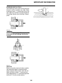
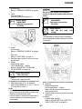
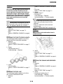
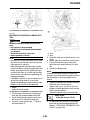
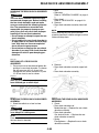
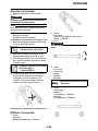
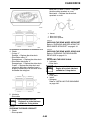
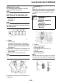
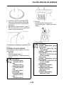
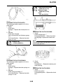
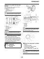
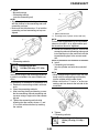
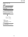
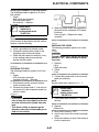
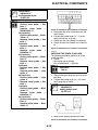
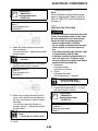
p. After the installation, check that the section
show “a” is flush with each other by touching the surface.
• Side machined face “a”
▲▲▲▲▲▲▲▲▲▲▲▲▲▲▲▲▲▲▲▲▲▲▲▲▲▲▲▲▲▲
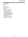
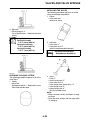
2. Select:
• Big end bearings (P1–P4)
EWA4S81014
WARNING
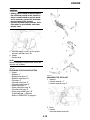
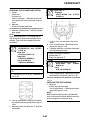
• When the bolt is tightened more than the
specified angle, do not loosen the bolt
and then retighten it.
Replace the bolt with a new one and perform the procedure again.
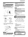
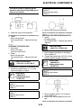
• If they are not flush with each other,
remove the connecting rod bolt and big
end bearing and restart from step "e". In
this case, make sure to replace the connecting rod bolt.
NOTE:
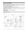
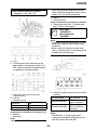
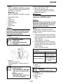
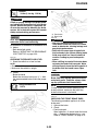
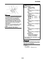
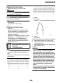
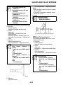
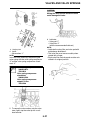
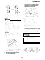
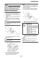
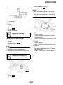
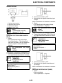
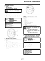
• The numbers “A” stamped into the crankshaft web and the numbers “1” on the connecting rods are used to determine the
replacement big end bearing sizes.
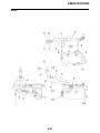
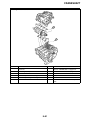
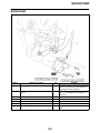
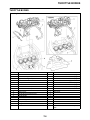
• “P1”–“P4” refer to the bearings shown in the
crankshaft illustration.
For example, if the connecting rod “P1” and
the crankshaft web “P1” numbers are “5”
and “2” respectively, then the bearing size
for “P1” is:
ECA4S81027
CAUTION:
• Do not use a torque wrench to tighten the
nut to the specified angle.
• Tighten the bolt until it is at the specified
angles.
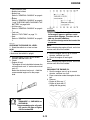
P1 (connecting rod) – P1
(crankshaft web) =
5 – 2 = 3 (brown)
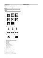
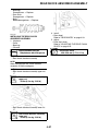
COLOR CODE
1
2
3
4
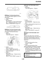
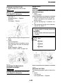
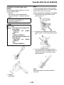
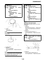
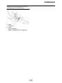
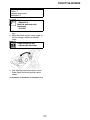
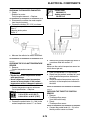
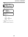
q. Remove the connecting rod and big end
bearings.
Refer to "REMOVING THE CONNECTING
RODS AND PISTONS" on page 5-62.
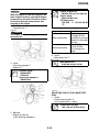
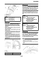
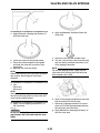
r. Measure the compressed Plastigauge®
width on the crankshaft pin.
5-67
Blue
Black
Brown
Green