1
SOLAR SYSTEM REGULATOR
DX 4102.G
User manual
May 2007
A0650_1.odt
05/2007
Solar system regulator DX4102.G
Duel Námestovo Ltd.
Content
1. INTRODUCTION..........................................................................................................................3
2. CONTROL FUNDAMENTALS...................................................................................................4
2.1 REGULATION FUNDAMENTALS............................................................................................................4
2.2 PUMP PERFORMANCE REGULATION......................................................................................................4
2.3 COLLECTOR TEMPERATURE SENSING...................................................................................................6
2.4 COLLECTOR OVERHEATING................................................................................................................6
2.5 AUXILIARY OUTPUT.........................................................................................................................6
2.6 SUBSIDIARY ENERGY SOURCE............................................................................................................6
2.7 SECONDARY LOOP PUMP...................................................................................................................7
2.8 REGULATION FAILURES BEHAVIOUR....................................................................................................7
2.9 ENERGY MEASURING........................................................................................................................7
3. SERVICE MANUAL.....................................................................................................................8
3.1 DEVICE DESCRIPTION.......................................................................................................................8
3.2 MENU STRUCTURE...........................................................................................................................9
Menu items...............................................................................................................................9
Service setting.........................................................................................................................10
3.3 REGULATION STATUS DISPLAY.........................................................................................................13
Regulation status....................................................................................................................13
Loop and collector temperatures...........................................................................................13
Energy and power given by collector panels.........................................................................14
3.4 FAILURE WARNING.........................................................................................................................14
4. INSTALLATION DIRECTIONS...............................................................................................15
4.1 DEVICE DIMENSIONS......................................................................................................................15
4.2 WIRE CONNECTIONS.......................................................................................................................16
4.3 INSTALLATION INSTRUCTIONS...........................................................................................................17
4.4 PC CONNECTIONS..........................................................................................................................17
5. TECHNICAL DATA....................................................................................................................20
A0650_1.odt
2
05/2007
Solar system regulator DX4102.G
Duel Námestovo Ltd.
1. Introduction
Regulator DX4102 (in next text regulator or device) is determined to regulation system consists
of solar collectors and a warm exchanger to gain warm energy and propagate it to the other systems.
Warm exchanger could be for example boiler, water basin or central heating system.
Regulator distributes warm carrying fluid to warm exchanger using actuator (pump) according to
set up temperature.
Device is equipped with timing facilities (programmable), which could use subsidiary energy
source (electric heating alternatively gas kettle-drum), providing heat limitations in loop.
Alternatively device can control secondary loop pump with time delay function.
Device is able to count up the energy given to warm exchanger.
DX4102.G behavior can be set up according to requested system parameters - "programming",
Programming uses four keys and Liquid Crystal Display (LCD) located at front panel of the device.
There can be found Light Emitting Diodes for power supply indication, system failure.
Regulator is equipped with current loop for data communication with Personal Computer.
Software named “EkoSolar” allow user to watch, modify and archive all important data and solar
system parameters.
A0650_1.odt
3
05/2007
Solar system regulator DX4102.G
Duel Námestovo Ltd.
2. Control fundamentals
2.1 Regulation fundamentals
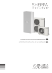
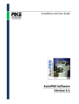
Regulator is one-loop (one-channel) differential regulator. Controlled system consists of solar
collectors, heat exchanger (A) and actuator, which distribute warm liquid to exchanger.
Regulator in a forever cycle watches temperatures at the exchanger and compares it with the
requested values. To pump warm liquid to exchanger two conditions must be fulfilled (in next text
abbreviated start pump conditions):
1. Insufficient heat exchanger temperature - measured exchanger temperature must be lower
than requested temperature (see "Menu-Temp"), set hysteresis 1 K.
2. Sufficient collector energy - collector temperature must be higher over minimum difference
"DeltaON" (see "Menu-Delta") than exchanger temperature to start pump. Pump stops if
difference falls below "DeltaOFF" - see 2.1. Parameter "Delta" is needed because of thermal
loss in piping between collector and exchanger.
T [°C]
Tcol
DeltaON
DeltaOFF
sufficient energy
Tex
t [sec]
Fig.1 Pump condition – sufficient collector energy
In case the pump conditions are fulfilled (exchanger has insufficient temperature and in collector
has sufficient energy), the loop will be switched on e.g. warm liquid will be pumped through this
loop. In case the loop has not fulfilled conditions for loading warm, pump stops.
Providing the loop have defined subsidiary energy source ("Menu-Service-Aux.Out=Heating")
and exchanger have insufficient temperature, but collector will not have sufficient energy for this
loop, it will be enabled subsidiary heating (see chap 2.6), that is time and temperature dependent.
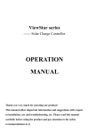
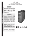
2.2 Pump performance regulation
Device can control the pump performance with pulse-width modulation – to decrease
performance the pump is switched of for some tens of milliseconds. Performance regulation is
enabled if "Menu-Service-PWMmod" is set up less than 100% (minimal 20%).
Pump performance is controlled (see chap. 2.2) if temperature sinks (collector to exchanger)
below DeltaON level. The performance is decreased to Pmin till an average value of DeltaON and
DeltaOFF, than it stays on Pmin till difference falls below DeltaOFF
A0650_1.odt
4
05/2007
Solar system regulator DX4102.G
Duel Námestovo Ltd.
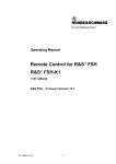
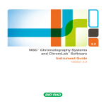
Exchanger A
Sk
Sh
Collector
T
P1
F
EH
Sa
Sx
Sensors (temperature): Sk-collector, Sh-subsidiary heating, Sx-return fluid , Sa – exchanger , F- flow meter
Actuator: EH – electrical heating element, P1 – pump; T - solar fluid tank
Fig.2 Block scheme of regulated system including subsidiary heating
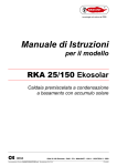
Sk
Exchanger A
Collector
Sa
T
P1
F
Sx
P2
Sensors (temperature): Sk-collector, Sa – exchanger, Sx-return fluid , F- pulse flow meter
Actuator: EH – P1 – pump, P2 – secondary loop pump, T - solar fluid tank
Fig.3 Block scheme of regulated system with secondary loop pump
Tcol
T [°C]
Tex + DeltaON
Tex + DeltaOFF
t [sec]
OFF
maximal speed
OFF
PWM band – slow down speed to Pmin
PWM band – Pmin speed
Fig.4 PWM band display – pump performance regulation
A0650_1.odt
5
05/2007
Solar system regulator DX4102.G
Duel Námestovo Ltd.
2.3 Collector temperature sensing
Collector temperature sensing is made by fixing collector sensor to collector corpus (see menu
Service-Sensor) and collector loop is "drain-back" type ("Sensor=Drain").
Drain-back system – is created of collector loop with FILL-in and FILL-out liquid (using solar
fluid tank) after an activation condition is fulfilled (collector temperature is over "DeltaT" value
greater than exchanger temperature). If it is true the pump is started for defined time A at full power
(the liquid is transported to collector fields), then the power is slowed down (necessary to keep the
flow level) for fixed interval B to get system niveau. In the end the collector loop is set to normal
process. After the finishing, (loading condition is false), the warm liquid is filled out from the loop
to fluid tank.
2.4 Collector overheating
If exchanger is full loaded (has enough energy) and the sun shines it could happen collector
overheating. That is why regulator is equipped with „overheating protection“ which can be
activated in menu (see chap. 3.2). As the collector temperature increases over 105 °C the primary
pump start running till the exchanger temperature reaches MaxTexc (see menu Service) or collector
temperature sinks below 100 °C. The overheating check stops if collector temperature increases
over 120 °C and will be started again if collector temperature falls below MaxTexc. This is
reasonable if the power (230V) is missing for some time (power failure).
2.5 Auxiliary output
Device is equipped with special output (X/Y), which can be used for cooperation with exchanger
or like standalone timer output. In case of exchanger the auxiliary output is used for:
1. subsidiary heating (see chap. 2.6)
2. secondary pump management (see chap. 2.7)
Stand alone timer output - non periodic timer – time window are give by table ( see "MenuTimer"). When configuring use of auxiliary output (see Servis – chap. 3.2) firstly the exchanger is
chosen then the way of its using (heating, secondary pump) and after the necessary parameters are
set.
2.6 Subsidiary energy source
Device is equipped with time functions ("Menu-Timer"), which is used to rank auxiliary
(subsidiary) energy source (electrical heating or gas kettle) for insufficient exchanger heat ("MenuService-Aux.Out=A-Aux.Out=Heating"). Auxiliary heating will be activated if (all conditions must
be fulfilled):
3. the time window condition is true, see menu "Timer"
4. the exchanger temp. is lower than start temp. (see "Servis-Aux.Out-...-Temp ON")
5. the exchanger (that with auxiliary heating) is not just being selected for warm loading
Auxiliary heating will be switched off, if some of conditions 1. and 3. is false, or the exchanger
temperature is higher than stop temperature (see "Servis-Aux.Out-...-Temp OFF"). There is left a
possibility to sense temperature in exchanger with another sensor which is fixed in top of
exchanger height - see example in Fig. 2 sensor Sh). Physically sensor is connected to S4
position.(see chap 4.2). This function will be activated automatically if sensor is present.
Aux.Out='–', then output XY will be controlled according to item "Timer", it means it is not bound
to loop conditions.
Auxiliary energy source will be automatically switched off at High Tariff (energy cost is
expensive), if the digital input is set to "Hi.Tarif" (viď "Service-Typ Inp"=" Hi.Tarif ") and
corresponding digital input is shorted.
A0650_1.odt
6
05/2007
Solar system regulator DX4102.G
Duel Námestovo Ltd.
2.7 Secondary loop pump
Regulator is able to use a secondary loop pump for a exchanger "Menu-ServiceAux.Out=Sec.Pump". If this is true then this output is is controlled together with corresponding
primary loop and it is stopped with preset time delay "Menu-Service-Aux.Out-...-PostPump".
Providing that exchanger sensor is localized at the pipe of secondary loop, the measured
temperature is real only for fluid circulating. That is why the regulator manages temperature check
function "Service-Aux.Out-...-CheckTem", where the regulator starts fluid pumping in a given
period "Service-Aux.Out-...-CheckTem-per", for a given interval "Service-Aux.Out-..
CheckTem- on", and it is enabled only if "sunshine" is set up (see chap.2.3
2.8 Regulation failures behaviour
If the sensor failure is found regulator behaves in a following way:
●
Collector sensor failure – warm liquid does not stop running (till the fault removing)
Exchanger sensor failure – the warm carrying fluid is pumped out till sensor malfunction
is removed, but only if collector temperature is higher than 60°C
●
Subsidiary sensor failure (S4) – subsidiary heating takes as reference value exchanger
sensor value (S2)
●
Return fluid sensor failure – temperature difference will be set 0 K, it means no instant
power (a energy will not be accumulated).
●
2.9 Energy measuring
Regulator can calculate the energy gained from collector. Energy is counted according the formula:
Q= c. m. dT, where c is relative warm capacity, m is mass and dT is temperature difference warm
carrying fluid (market name Solaren).
Fluid mass is evaluated as m= q. V, where V is volume and q is pumped fluid density (the value
is temperature dependent). The volume is either measured by flow-meter (see chap. 3.2) either
counted out from time of fluid flow and given flow per a minute.
The temperature difference is given like collector to exchanger output temperature (return fluid
sensor needed) or it is fixed difference set by DiffTemp (see chap.3.2). For the second case the
measuring is for informative purpose only.
Relative warm capacity and fluid density is assumed for SOLAREN (non diluted) !
Energy is counted up as cumulative number increasing for each period. Counter can be cleared
manually by user see “Service-Energy-Clear Ac” or “Records-Counter-date nul”. After reaching
10000 kWh it is cleared in automatic way. Day registers (32 days backward) - keep energy for each
day. The records can be seen in “Records” menu (chap.3.2).
Instant collector power represents (gained) energy amount per fixed period. Periode is given as
the delay between two flow-meter pulses or is set fixed one minute.
A0650_1.odt
7
05/2007
Solar system regulator DX4102.G
Duel Námestovo Ltd.
3. Service manual
3.1 Device description
Regulator consists of (seen from the front panel) LCD display (two rows per 8 characters), a four
key keyboard (KBD) and LED indicators (PWR a ERR), see Fig. 6
With display and keys user can get an information about regulation status, find out measured and
requested values or edit parameters and so on. Parameter accessing is realized by menu structure.
Fig.5 Regulator front panel
Keyboard is represented with a group of four keys. The meaning of keys follows:
F ...Function key – quit without change for editing (Escape) a return to upper level
E ...Enter – confirmation for editing value (Enter) – stores value and moves to next item
▲...menu items change in defined direction, press = +1, hold dynamic value increasing
▼...menu items change in defined direction, press = +1, hold dynamic value increasing
▲,▼
at the same time pressed – setting up minimal value for selected parameter
Two light indicators signalize:
PWR – power supply presence
ERR - system failure (ERR flashes) – sensor or internal regulator failure see chap. 3.4
A0650_1.odt
8
05/2007
Solar system regulator DX4102.G
Duel Námestovo Ltd.
The processed values can be seen in two display windows. Window change involves "E" key see
3.1, window description can be found in chap.3.3. Pressing "F" key enables menu display for
requested regulation parameters, date, time and service parameters. Detail menu description covers
chap 3.2.
Regulation status
Collector,
exchanger
temperatures
Gained energy
instant collector
power
11:25 /B
08-03 E
F
menu
E
F
K 82 X65
A39 R45
Menu
Service
E
F
1234.56k
003.21kW
Fig.6 Regulation status versus menu
3.2 Menu structure
Menu is involved by pressing "F" key if regulation process display is active. Menu items can be
selected by ▲,▼ items, confirmation enables "E" key, current level quits "F" key. Changed item is
flashing. After reaching the maximal value the minimal is set and vice versa.
Menu items
♦ Date
date setting. Firstly day in a month, then month an in the end the year. If date is set
incorrect (30.02.2004) cursor (_) returns back to day of month position.
♦ Time
time setting. First is set summer (S) / winter (W) time then hours and minutes in the
end. Choosing summer or winter involves time the hours are set up automatically.
♦ Timer
timer setting - maximal 8 time interval during a day (00:00-23:59). First time to
switch on , then switch off (value 24:00 represents switch off at 00:00).
♦ Records day gained energy records (see Fig.9)
Counter shows cumulated energy (from time of last clearing)
Energ.QH gained energy corresponding to last quarter of an hour
Energ. D gained energy for last 32 days (each day individually)
♦ Manual manual setting outputs of regulator – three modes: "Aut" = controlled by
regulation algorithm, "ON" – always ON, "OFF" – always OFF
♦ Delta
setting start and stop difference for exchangers (Kelvin values). Start difference
DeltaON is minimal temperature difference (collector to exchanger temperature) to start pump
running. Stop difference DeltaOFF minimal value to stop pump.
♦ Temp
exchanger requested value (ºC)
♦ Service service parameters setting
A0650_1.odt
9
05/2007
Solar system regulator DX4102.G
Duel Námestovo Ltd.
Main menu
Vertical moving: ↑↓, Horizontal moving: E
Menu
E
Menu
Date
Date setting
E
Timer #1
06:30
auxiliary heating timer
Menu
Records
E
Date
27.07.02
Month
Year
E
Time
S 11:30
S-summer time
W-winter time
Time setting
Menu
Timer
E
Time
S 11:30
E
Date
27.07.02
Day in a month
E
Menu
Time
E
Date
27.07.02
Time
S 11:30
Hours
Minutes
next interval (max.#8)
Edit interval number
E
Timer #1
06:30
Hour to start
E
Timer #1
10:00
Minute to start
Timer #1
10:00
E
Hour to stop
Minute to stop
Processed energy records (log) - see menu Records
Output name
Menu
Manual
E
Manual
PN= AUT
manual output set up
Menu
Delta
E
E
AUT= automat, ON- always on, OFF - always off
Delta[K]
A 10 02
E
Service menu
E
Delta[K]
A 10 02
starting difference
stopping difference
Temp
A= 60°C
Exchanger A temperature
Exchanger requested value
Menu
Service
next outputs
Exchanger A
Collector to exchanger difference
Menu
Temp
E
Service
0715
E
Service
0715
day in a set month
E
Service
xxxxxxx
current hour
see Service menu
Access password
Fig.7 Regulator menu
Service setting
Service menu access is protected by knowledge of code. Service settings should be set at
beginning (first installation) that is why the password is "ddhh" needed (dd day in a set month and
hh hour set in device). Service menu items::
♦ Sensor
collector sensor localization (see chap.2.3). There are two possibilities:
➢ Drain
at collector corpus (see chap. 2.3)
•
Delta T
temperature difference
•
Time A
power maximal (fill in) time
•
Time B
power minimal (stabilize flow) time
♦ Prot.Col collector overheating protection (Enable=Yes, Disable= No). If enabled next
parameter appears MaxTec.
♦ Aux.Out auxiliary output XY definition. Firstly must be defined exchanger (if none XY
output will be by "Timer" variable controlled), then the purpose must be defined: heating (see
2.6) or secondary loop pump (see 2.7). For heating the start and stop times are set, for secondary
pump off time delay and pipe sensing items (similar to collector pipe) see "Sensor- Pipe"
♦ PWMmod actuator pump performance (see chap. 2.2) for A loop (20-100%). 100% means full
pump speed.
♦ ParEnerg parameters for gained energy from collector panels (see 3.2):
A0650_1.odt
10
05/2007
Solar system regulator DX4102.G
Duel Námestovo Ltd.
➢ Flow
flow meter setting – if pulse flow meter is used (Flow imp=Yes), flow
is set up in liters / pulse, if no flow meter is used then in liters / pulse.
➢ BackTemp
return fluid sensor using (No/Yes = used), for no sensor it is
recommended set up temperature difference of collector (between output and input).
➢ Clear Ac
clears gained energy counter (accumulator)tupom).
♦ Com.par serial line communication parameters: address and baud rate
➢ adr device address (0-19). Important for more regulators at the line, otherwise 0.
➢ S
baud rate (1200, 2400, 4800 or 9600 Baud)
♦ Mode I/O input / output parameters
➢ Inv.Out.
output: Direct ("Norm") or inverted ("Inve"). If inverted and it is a
demand to switch on, the output will be switch off and vice versa.
➢ Inv.Inp.
digital inputs D1 and D2 ("Norm"/"Inve") – if NORM active for short,
otherwise active for open circuit
➢ Using D2
Digital input D2: "no use" – free, "Sunshine" – extern light intensity
sensor, "Hi.Tarif" – disable electrical heating if High tariff signal appears
menu Records
Records
Records
Counter
Vertical move: ↑↓, Horizontal move: E
E
A= [kWh]
1234.67
date nul
20.04.05
Gained energy counter
Gained energy value (after 10000.00kWh> 0 .0 kWh)
Energy value clearing menu
E
Clear
No
?
Clear
Yes
?
E
Date of last clearing
Accept clearing
Backward day number(0 - current day)
Backward date
Records
Energ. D
E
00 25.04
123.5kWh
Gainned energy of selected day
Day energy registers
Records
Energ.QH
E
Backward day change (0-99)
00 12:45
12.35kWh
Quarter of an hour registers
E
A quarter of an hour change
(from 00:00 to current time)
Next day in backward direction
Amount of energy per given quarter
Fig.8 Menu Records
A0650_1.odt
11
05/2007
Solar system regulator DX4102.G
Duel Námestovo Ltd.
menu Service
Service
Service
Sensor
Vertical move: ↑↓, horizontal move: E
E
E
Sensor
Drain
work mode
collector sensor position and mode
Service
Prot.Col
E
Prot.Col
No
Service
Aux.Out
E
Yes
Aux.Out
A
E
Service
ParEnerg
Service
Com.par.
65
E
Aux.Out
Sec.Pump
05
Aux.Out
Timer
(20-100%)
E
E
E
Mode I/O
Inv.Out.
E
Output modes
Mode I/O
Using D2
E
ON
°C
min
Yes
E
E
per15min
on030sec
time of temperature sensing
at pipe (10-200 second)
Com.par.
S=9600Bd
Baud rate
Inv.Inp.
D1=Norm
E
Inv.Out.
PN=Norm
next input modes
Output modes:
- Norm - direct
- Inver - invert
Input name
Input modes
55
temperature sensing period
(5,10,15,20,30 minutes) 1)
device line address
Mode I/O
Inv.Inp.
°C
per15min
on030sec
Aux. output as timer
Com.par
Adr=00
°C
pump stop delay (0-30 min)
see menu "ParEnerg"
E
Time B
060 sec
Temp. checking if sensor is
fixed at pipe
E
PostPump
CheckTem
auxiliary output =
secondary pump
PWMmod A
min=100%
PC communication parameters
Service
Mode I/O
E
Aux.Out
Heating
auxiliary output =
heating
PWM pump performance
E
Start temperature(0-99 °C)
(must be lower than stop)
E
Temp OFF
Temp
Stop temperature (0-99 °C)
loop designed for
subsidiary output
: –,A
E
95
Enabled
auxiliary output using
Service
PWMmod
Time A
060 sec
stabilise time
FILL-in time
Max.
warm
exchanger
minimal gradient to START
temp.at collector pannel
E
Prot.Col
MaxT.exc protection
Disabled
Overheating enabled
E
Delta T
15
K
E
next output modes
Output name
indikátor vysokého tarifu
Using D2
no use
not used
digital input modes
Using D2
Sunshine
Using D2
Hi.Tarif
light intensity sensor
Fig.9 Menu Service
A0650_1.odt
12
05/2007
Solar system regulator DX4102.G
Duel Námestovo Ltd.
menu Energy
Vertical move: ↑↓, horizonatal move: E
ParEnerg
Flow measuring parameters
ParEnerg
Flow
E
E
Flow
imp=No
Flow
01.00l/m
No flow meter used
E
Flow
imp=Yes
ParEnerg
BackTemp
E
BackTemp
sens=Yes
Return flow sensor using
ParEnerg
Clear Ac
E
Flow (X.00-X.99
liter per min
E
Flow
01.00l/i
Flow (X.00-X.99
liter pre pulse)
Flow (0-99 liter pre pulse)
BackTemp
sens=No
Used
Flow
01.00l/m
Flow (0-99 liter per min)
Flow
01.00l/i
Pulse flow meter used
E
E
DiffTemp
10
°C
Not used
Return flow semnsor not used
(estimated collector difference)
(0-99°C)
Clear Ac
Yes
Energy accumulator
clearing
Acknowledgement
Fig.10 Menu Energy
3.3 Regulation status display
Regulation status
The upper line displays: time and loop activity – if loop works, the rotating icons and the name
of the exchanger (A) and the flashing character representing non standard warm pumping: 'p'- the
pipe temperature sensing (sensor at the pipe), 'e' – sensor failure, 'H' – collector overheating.
The lower line displays: date and the character representing X output status ('E', auxiliary energy
source, 'S', secondary loop pump, 'T', only timer), and failure report, if any happened.
Flashing character - the reason for pump to run:
'e' – sensor failure
'H' – collector overheating
'z' - start FILL- in
's' - keep the flow
'w' – wait for temperature difference
'b' - blok fluid flow
Rotating pump icon
Time
11:25p×A
16-09T!!
Date
'E' – auxiliary heating active
'S' – secondary loop pump active
'T' – timer active
Active loop indicator
Failure (flashing alternate with !!):
HW - device
SN - sensor
MU - manual mode
Fig.11 Regulator status
If system detects a failure, the double „!!“ alternates flashing with code of the failure.: HWhardware error, SN – sensor error, MU – manual mode.
Loop and collector temperatures
The first line displays collector temperature, the lower one exchanger temperature. If the return
fluid sensor is used, its temperature appears too.
A0650_1.odt
13
05/2007
Solar system regulator DX4102.G
Duel Námestovo Ltd.
For short circuit sensor flashing 'x' appears, for open sensor circuit '-' appears and if the
temperature is less or greater then display width then flashing '9' appear.
Collector
temperature
Return fluid temp
K102 X70
A39 H45
Exchanger
A temperature
Auxiliary heating
temperature
Fig.12 Temperatures display
Energy and power given by collector panels
Upper line displays energy (kWh) propagated from collector from last clear (see Records).
Lower line keeps instant power (kW) of collector panels. (see 3.3).
Gain energy from collector
[kWh]
accumulated from last clear
1234.56k
003.21kW
Instant gained power
Fig.13 Energy and power of collector panel
Through pressing the arrow keys (at keyboard), next window appear. There can be seen
temperature difference and computed value of flow converted to minutes (liters per minute).
Temperature difference
collector – return pipe
34.6°C
12.34l/m
Current flow value
Fig.14 Temperature difference and flow value
3.4 Failure warning
If some failure happened, the ERR light start to flash and display shows the error code (see
chap.3.3).
There are two main failures - system failure, sensor failure:
1. Sensor failure: instead of temperature value the "–" (open circuit sensor), "x" (short
circuit sensor) or "?" (Analog to Digital Converter failure) character flash. The error code
"SN" flashes.
2. System failure: ADC failure instead of temperature "?" flashes, Real Time Clock failure
instead of time and date "?" appear. The error code "HW" flashes.
3. Manual mode: if some output should be switch on and it is not possible because of
manual switch position, regulator shows flashing "MU" to annotate user.
A0650_1.odt
14
05/2007
Solar system regulator DX4102.G
Duel Námestovo Ltd.
4. Installation directions
4.1 Device dimensions
Device is fixed at wall through metal console, that must be first installed. Regulator is
manufactured in form of plastic box (125x83x35), that fixes at mentioned console..
Fig.15 Device dimensions
A0650_1.odt
15
05/2007
Solar system regulator DX4102.G
Duel Námestovo Ltd.
4.2 Wire connections
Regulating system consists of: regulator, sensors and actuators (pumps). Sensors and actuators
are connected to installation bracket, localized under the cover of the device.. Wiring diagram is
given in.
10.
fuse
8.
9.
P+ P- S3 AG S4 AG
L
N
P
N
1.
2.
X
Y
D1 DG D2 S1 AG S2 AG
3.
4.
5.
6.
7.
Fig.16 Wiring diagram
1. power supply 230V~ (1)
2. output PN (2) – pump
3. potential- free output X / Y (3) – auxiliary output (4)
4. D1
digital input – pulse flow meter
5. D2
digital input - not used, High Tariff ("HiTariff"), sunshine ("Sunshine")
6. S1
collector temperature sensor
7. S2
warm exchanger temperature sensor
8. S3
return flow temperature sensor
9. S4
sensor for auxiliary output
10. P+, Pcommunication line PC (current loop 20mA)
Notes:
1) The current flowing in this wire goes through fuse to PN output. !! Warning for the current
value which is limited by fuse. Power actuators should be connected using additional relays
or power relays!
2) As switching element used triac, power output 230V AC, maximal 1A
3) Relay contacts, 230V AC, 30V DC. Current limited to 1A - directly may be used load with
dissipation max 230W (@ 230V~), if more power is required an additional relay or power
relay must be used!
4) Auxiliary output may be used for: additional heating or secondary circuit pump or timer
only
X
D1
DG
Y
L
N
P
a) P(ump) output
+5V
D2
N
b) X / Y output
c) digital inputs D1, D2
Fig.17 Input - output equivalent connections
A0650_1.odt
16
05/2007
Solar system regulator DX4102.G
Duel Námestovo Ltd.
4.3 Installation instructions
An installation of the device should be made according to recommended application scheme
keeping following rules:
1. Firstly sensors, then actuators and in the end power line. For sensors is recommended
twisted pair line (MK 2x0.75/TP 03/41/MTP 226/70), keeping distance from power wires
(min.30 cm) and shield connect to PE wire.
2. Before screwing wires to terminal, put the sleeve endings to the end of the wires
3. Just before power supply connection check all input and output wires (sensors, actuating
terms) for disconnection or short-circuit
4. Turn on the safety fuse and test function of actuators in manual mode
5. Check measured temperature values at collector, then in the loops and set initial system
parameters.
4.4 PC connections
Device offers possibility for connection to serial port of personal computer. This connection
enable user to:
∗ comfortable set up all parameters of regulation
∗ not limited keeping records of gained energy
∗ watch regulation process from the living room „sofa“ and supervisor regulation
From the hardware side of connection, there is a necessity for communication (physical layer
converter for RS232 <=> 20 mA current loop) converter DX 5220, which is connected with two
wires to connector field (P+, P–). Keep polarity during connection, right connection forces LED in
DX5020 to light (pins of DX5020 should have about 2.7V), wrong connection (0,7V).
A0650_1.odt
17
05/2007
Solar system regulator DX4102.G
Duel Námestovo Ltd.
PW
ER
F
E
DX 4102
Fuse holder
Serial PC port
(RS232 or USB)
SOLAR
REGULATOR
+
DX5220
P+ P- S3 AG S4 AG
L N P N X Y
Power fuse
L
PE
N
Sensors:
Actuators:
Flow measuring:
Note:
D1 DG D2 S1 AG S2 AG
P1
F
Sk Sa
Sh Sx
PO
Sk – collector temperature, Sa – exchanger temperature, Sx – return flow, Sh – auxiliary heating
PO – power relay, that controls auxiliary heating (3 phase heating element), P1 – pump
F -flow-meter connected to digital input
installation bracket and fuse holder are under the top cover
Fig.18 An example of regulator connections
A0650_1.odt
18
05/2007
Solar system regulator DX4102.G
Duel Námestovo Ltd.
2.
DX 4102
1.
85.5 mm
Open the regulator
coverregulátora.
by the tool
Nástrojom
otvoriť kryt
50.5 mm
Podľa priloženej šablóny navrtať diery
According
to included scheme drill holes for dies.
pre zápustky.
Press dies to the prepared holes
Do dier inštalovať zápustky.
the zaskrutkovať.
uppermost screw down.
VrchnúInsert
skrutku
3.
Zavesiť
nauppermost
vrchnú skrutku.
Hang upregulátor
regulator on
screw
DX 4102
4.
5.
Po pripojen í elektrickej inštalácie
After
wire connection
check
out function,
a skontrolovaní
funkcie
nasunúť
kryt
push
down
the
cover
to
the
basis.
regulátora na základňu.
ZaskrutkovaťInsert
dve spodné
skrutky.
the last two
screws
Fig.19 Device assembling
A0650_1.odt
19
05/2007
Solar system regulator DX4102.G
Duel Námestovo Ltd.
5. Technical data
Power supply:
230V/50Hz
Power rating:
230VA
Output voltage:
230V/50Hz
Output current limitation:
1A
Fuse rating:
2 A, type T (slow reaction)
Sensor temperature range:
-25 ÷ +170 °C
Sensors:
DX 1083 (DUEL Námestovo,
[1000 Ohm @ 25°C, 1670 Ohm @ 100°C)]
Difference range:
0 ÷ 25 K
Temperature accuracy:
± 1.5 K
Time back up:
7 days
Insulation protection:
IP20
Operating ambient conditions.
Ambient temperature:
5 ÷ 50 °C
Air humidity:
max 90% @ 30°C
Air pressure:
70 ÷ 106 kPa
Warranty:
●
Manufacturer provides guarantee 36 month from the day of delivery
●
Warranty refers only to the fault, which come into being by normal operation with sensor
delivery. Do not refer to fault, which arises by inexpert service, incorrect storage, unsuitable
environment and high power activity (spontaneous disaster, flood, fire, atmospheric
discharge and so on.)
●
User looses claim to warranty at devices, on those was execution hit
●
Warranty also after-warranty service guards manufacturer
A0650_1.odt
20
05/2007
Solar system regulator DX4102.G
Notes:
A0650_1.odt
Duel Námestovo Ltd.
21
05/2007
Solar system regulator DX4102.G
A0650_1.odt
Duel Námestovo Ltd.
22
05/2007
Solar system regulator DX4102.G
A0650_1.odt
Duel Námestovo Ltd.
23
05/2007
Solar system regulator DX4102.G
DUEL Námestovo s. r. o.,
Telefon / Fax:
Email:
Http:
A0650_1.odt
Duel Námestovo Ltd.
Florinova 928 / 9, SK - 029 01 Námestovo
+421 (0) 43 5591 092 / +421 (0) 43 5591 091
[email protected]
www.duel-ltd.sk
24
05/2007