1
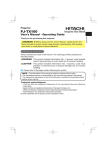
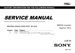
No.0546E
YK
PJ-TX100
SERVICE MANUAL
(C11H)
Warning
The technical information and parts shown in this
manual are not to be used for: the development,
design, production, storage or use of nuclear, chemical,
biological or missile weapons or other weapons of
mass destruction; or military purposes; or purposes that
endanger global safety and peace. Moreover, do not
sell, give, or export these items, or grant permission for
use to parties with such objectives. Forward all inquiries
to Hitachi Ltd.
Caution
Be sure to read this manual before servicing. To assure safety from fire, electric shock, injury, harmful
radiation and materials, various measures are provided in this Hitachi Multimedia LCD Projector. Be
sure to read cautionary items described in the manual to maintain safety before servicing.
Service Warning
1. When replace the lamp, to avoid burns to your fingers. The lamp becomes too hot.
2. Never touch the lamp bulb with a finger or anything else. Never drop it or give it a shock. They may
cause bursting of the bulb.
3. This projector is provided with a high voltage circuit for the lamp. Do not touch the electric parts of
power unit (main), when turn on the projector.
4. Do not touch the exhaust fan, during operation.
5. The LCD module assembly is likely to be damaged. If replacing to the LCD LENS/PRISM assembly,
do not hold the FPC of the LCD module assembly.
6. Use the cables which are included with the projector or specified.
Contents
1.
2.
3.
4.
5.
6.
7.
Features -----------------------------------------------2
Specifications -----------------------------------------2
Names of each part ---------------------------------3
Adjustment --------------------------------------------5
Troubleshooting ------------------------------------ 12
Service points -------------------------------------- 17
Wiring diagram ------------------------------------- 29
8. Disassembly diagram----------------------------- 34
9. Replacement parts list---------------------------- 37 Updated 4/21/05
10.RS-232C commands ----------------------------- 38
11. Block diagram -------------------------------------- 47
12.Connector connection diagram ---------------- 48
13.Basic circuit diagram ------------------------------ 49
SPECIFICATIONS AND PARTS ARE SUBJECT TO CHANGE FOR IMPROVEMENT.
Multimedia LCD Projector
May 2004 Digital Media Division
Version 0546E.1
PJ-TX100(C11H)
1. Features
Super focus ED (Extra-low dispersion) lenses are adopted for the highest possible image quality.
720P wide LCD panels realize faithful reproduction of high-definition images.
Motorized iris control is provided for realizing film-like images with blacker black.
1.6x zoom lens and the optical lens shift allow flexible installation and viewing position.
2. Specifications
Liquid
Crystal
Panel
Drive system
Panel size
Number of pixels
Lamp
Video Input
System
Level
TFT active matrix
1.8cm (0.7type)
1280 (H) × 720 (V)
150W UHB
NTSC,PAL(BGDHI),SECAM,PAL-M,PAL-N,NTSC4.43,PAL60
Composite 1.0±0.1Vp-p(75Ωtermination)
S-Video Y : 1.0±0.1Vp-p(75Ωtermination)
C : 0.286±0.1Vp-p(NTSC burst signal,75Ωtermination)
0.3±0.1Vp-p(PAL/SECAM burst signal,75Ωtermination)
Component
Y : 1.0±0.1Vp-p(75Ωtermination)
CB/PB : 0.7±0.1Vp-p(75Ωtermination)
CR/PR : 0.7±0.1Vp-p(75Ωtermination)
RGB input /
output
Analog RGB
Sync.
Power supply
Power consumption
Dimensions
Weight
0.7V p-p (75Ωtermination)
TTL level
AC100~120V / 2.4A , AC220~240V / 1.3A
220W
340(W) × 110(H) × 280(D) mm (No including protruding parts)
4.4kg(9.7lbs)
Temperature
Operation : 5~35°C
Accessories
Power cord
PJ-TX100W x 3 (US, UK, Europe)
PJ-TX100E x 2 (UK, Europe)
PJ-TX100U x 1 (US)
Component cable x 1
Rivet (for Lens cap) x 1
Strap (for Lens cap) x 1
2
Storage : -20~60°C
Remote control transmitter x 1
Battery (for Remote control) x 2
User’s manual
Quick guide x 1
Safety guide x 1
Operating guide book x 2 or 3
PJ-TX100(C11H)
3. Names of each part
Parts names
Projector
Horizontal
lens shift dials
Vertical
lens shift dials
Zoom knob
Filter cover
(An air filter is inside.)
Focus knob
Remote sensor
Exhaust vent
Elevator button
is on the both sides.
Elevator foot
is on the both sides.
Lens cover
Lens
radiates powerful light for projecting an image.
Elevator foot
Elevator foot
Lamp cover
Strap hole
Intake vent
(Bottom of projector)
Exhaust vent
Elevator foot
Elevator button
Power switch
AC inlet
DVI-D port
Y
COMPONENT
VIDEO ports
Y
CB/PB
CR/PR
DVI-D
S-VIDEO
COMPUTER
CB/PB
VIDEO
CONTROL
CONTROL port
CR/PR
COMPONENT VIDEO
COMPUTER
port
VIDEO port
S-VIDEO port
3
PJ-TX100(C11H)
STANDBY/ON button
prepares for turning the power
on/off.
POWER indicator
tells the state of power supply.
MENU button
operates the menu function.
INPUT button
toggles between the
signal ports.
COMPONENT
VIDEO
TEMP indicator
lights or blinks when any problem about
internal temperature has happened.
LAMP indicator
light or blinks when any problem about
the lamp has happened.
Cursor buttons
works for adjusting or menu controlling.
ENTER button
proceeds to the next operation at the
menu functions.
RESET button
cancels the adjustment in progress.
* Note that the items whose functions
are performed simultaneously with
operating are nor reset.
STANDBY/ON
POWER TEMP
LAMP
MENU
ENTER
INPUT
RESET
S-VIDEO
VIDEO
DVI-D
COMPUTER
Remote control transmitter
MODE button
POWER button
toggles between
prepares for turning the
the modes for the
power on/off.
picture type.
(the same as the
STANDBY/ON button above.)
OPT BLK button
POWER
LIGHT
toggles between the
modes for the optical black.
ASPECT button
OPT BLK MODE MEMORY
toggles between the modes for
IRIS
ASPECT
the aspect ratio.
Cursor buttons
ENTER
(the same as the above.)
MENU button
RESET
MENU
(the same as the above.)
BRIGHT CONTRAST COLOR
BRIGHT buttons
controls the brightness of the
whole screen.
DVI button
DVI
PC AUTO
selects the DVI-D port input.
COMPO S-VIDEO VIDEO
PC button
selects the COMPUTER port input.
COMPO button
selects the COMPONENT
VIDEO port input.
4
LIGHT button
turn on/off the back light for
the remote control buttons.
MEMORY button
toggles between your
adjustments.
IRIS button
toggles between the modes
for the iris.
ENTER button
(the same as the above.)
RESET button
(the same as the above.)
CONTRAST buttons
controls the contrast of the
whole screen.
COLOR buttons
controls the color of the whole
screen.
AUTO button
executes automatic
adjustment.
VIDEO button
selects the VIDEO port input.
S-VIDEO button
selects the S-VIDEO port input.
PJ-TX100(C11H)
4. Adjustment
4-1 Before adjusting
4-1-1 Selection of adjustment
When any parts in the table 4-1 are changed, choose the proper adjusting items with the chart.
Table 4-1: Relation between the replaced part and adjustment
Adjustment
Replaced
Convergence E-POS
part
(Chap.4-2) (Chap.4-3)
Ghost
(Chap.4-4)
Flicker
(Chap.4-5)
NRSH
(Chap.4-6)
White
balance
(Chap.4-7)
Color
uniformity
(Chap.4-8)
AIR
IRIS
SENSOR
(Chap.4-9) (Chap.4-10)
Dichroic
optics unit
LCD/LENS
prism
assembly
PWB
assembly
Main
Lamp
unit
assembly
PWB
assembly
Sensor
: means need for adjustment.
: means not need for djustment.
: means recommended.
4-1-2 Setting of condition before adjustment
1. Before starting adjustment, warim up projector
for about 10 minutes.
2. Set Zoom Wide to Max. And project an image
with more than 1m (40 inches) in diagonal size.
3. Set the lens position to the center, where you
feel click, using horizontal and vertical lens shift
dials.
4. Normalizing the video adjustment
Press the [MENU] button to display the Easy
menu. If Advance menu comes up, move to the
Easy menu.
Select RESET in the Easy menu and press [ ]
6. Select PICTURE > COLOR TEMP > CUSTOM
in the Advance menu, then press [ ] or [ENTER]
button to display the equalizing window. Set all
the values of OFFSET and GAIN in the window
to zero.
Caution: Before this performance, make a note
of your customer’s adjustments, because the
data is overwritten.
7. Perform all adjustments from the FACTORY
MENU.
Perform the following operations to display the
FACTORY MENU.
a. Press the [MENU] button of remote control to
display the Easy menu. (If the Advance menu
appears, move to the Easy menu from EASY
MENU.)
b. Select the [RESET] in the Easy menu, and
then press the [ ] or [ENTER] button.
c. Next, press the [RESET] button one time.
And hold the [RESET] button for 3 seconds
or more (the FACTORY MENU will appear).
or [ENTER] button to open the RESET menu
window. Choose EXECUTE with [ ] button.
Note that no signal input may have the projector
reset its adjustments.
5. Select PICTURE > GAMMA in the Advanced
menu to set to DEFAULT1.
Note that PICTURE menu is not selectable with
no signal input displayed.
5
PJ-TX100(C11H)
4-2 Convergence adjustment
Adjustment procedure
1. Open FACTORY MENU and then select
OPTION > CNV-V. Use R and/or B so that
three colors of images can be converged at
center, top and bottom of the screen.
2. In the same way, select OPTION > CNV-H and
use R and/or B so that three colors of images
can be converged at center, left and right of the
screen.
Signal pattern for internal adjustment
4-3 E-POS adjustment(vertical bars adjustment)
Adjustment procedure
1. Make this adjustment after completing the
adjustment 4-2 Convergence adjustment.
2. Open FACTORY MENU. Select DAC-P > E-POS
> R and use it so that vertical bars can disappear.
3. In the same way, select DAC-P > E-POS > G
and use it so that vertical bars can disappear.
4. In the same way, select DAC-P > E-POS > B
and use it so that vertical bars disappear.
Signal pattern for internal adjustment
112/255
4-4 Ghost adjustment
Adjustment procedure
1. Make this adjustment after completing the
adjustment in 4-3.
2. Use DAC-P - GHOST - R: in the FACTORY MENU
to adjust so that R color ghost is at a minimum.
(Set the adjustment value to default, and then
raise the value. When a ghost appears to the left
of a vertical line, reduce the value by 4 steps.)
3. In the same way, use DAC-P - GHOST-G: in
the FACTORY MENU to adjust so that G color
ghost is at a minimum.
4. In the same way, use DAC-P - GHOST-B: in
the FACTORY MENU to adjust so that B color
ghost is at a minimum.
Signals for internal adjustment
30%
30%
0/255
112/255
6
PJ-TX100(C11H)
4-5 Flicker adjustment (V.COM adjustment)
Adjustment procedure
1. Make this adjustment after completing the
adjustment in 4-4 Ghost adjustment.
2. Use DAC-P - V.COM - R: in the FACTORY
MENU to adjust so that the flicker at the center of
the screen is less than the flicker at the periphery.
(When the flicker is about the same across the
whole screen, adjust so that the flicker at the center
of the screen is somewhat less than elsewhere.)
3. In the same way, use DAC-P - V.COM-G: in the
FACTORY MENU to adjust the G color flicker.
4. In the same way, use DAC-P - V.COM-B: in the
FACTORY MENU to adjust the B color flicker.
Signals for internal adjustment
4-6 NRSH adjustment (vertical stripe adjustment)
Signals for internal adjustment
Adjustment procedure
1. Make this adjustment after completing the
adjustment in 4-5 Flicker adjustment.
2. Use DAC-P - NRSH - R: in the FACTORY
MENU to adjust so that the vertical lines spaced
every 6 dots are as inconspicuous as possible.
(Reduce the adjustment value when black
stripes appear in the 2nd or 3rd tone from the
black side. Note that when the adjustment value
is lowered, white stripes may appear in the 2nd
or 3rd tone from the bright side. Should this
happen, adjust so that the stripes are as inconspicuous as possible.)
3. In the same way, use DAC-P - NRSH - G: in the
FACTORY MENU to adjust vertical stripes of G color.
4. In the same way, use DAC-P - NRSH - B: in the
Adjustment menu to adjust vertical stripes of B color.
64
/255
88
/255
112
/255
136
/255
160
/255
Press ENTER key
160
/255
136
/255
112
/255
88
/255
64
/255
4-7 White balance adjustment (visual inspection)
Preparations
1. Perform these adjustments after the NRSH
adjustment described in Section 4-6.
2. Reset gamma correction before adjustment.
Place the cursor on [GAMMA] in the FACTORY
MENU, press the [RESET] key and select [DEFAULT].
Adjustment procedure
1. First, adjust the G color.
2. Select GAMMA, SUB-CNT, and G: in the FACTORY
MENU. If the background is white solid, press the
[ENTER] key on the Remote control transmitter to
change to [G] monochrome in the 33-tone grayscale.
3. Adjust GAMMA, SUB-CNT, and G: in the FACTORY MENU so that brightness of 33 steps is
best.
4. Don’t adjust GAMMA, SUB-BRT, and G: in the
FACTORY MENU. Because we want to keep
the best contrast ratio.
5. Then adjust colors R and B.
6. Select GAMMA, SUB-CNT, and G: in the FACTORY
MENU. If the background is white solid, press the
[ENTER] key on the Remote control trasmitter to
change to [W] monochrome in the 33-tone grayscale.
7. Adjust GAMMA, SUB-BRT, R: and B: in the
FACTORY MENU so that low-brigtness white
balance is best.
8. Adjust GAMMA, SUB-CNT, R: and B: in the
FACTORY MENU so that middle-brightness
white balance is best.
9. Repeat steps 7 to 8 above, and adjust so that
brightness white balance of 33 steps is best.
7
PJ-TX100(C11H)
4-8 Color uniformity adjustment
Preparations
1. Perform these adjustments after the white balance
adjustment described in Section 4-7.
6. To temporarily turn correction off, place the
cursor on [C.UNIF.] in the Adjust Tone menu and
press the [ ] key. The ON/OFF menu appears.
2. Make a color uniformity adjustment for the following four tones.
MIN tone (approx. 7% input signal)
MID-L tone (approx. 21% input signal)
MID-H tone (approx. 50% input signal)
MAX tone (approx. 75% input signal)
3. Place the cursor on [C.UNIF.] in the FACTORY
MENU and press the [ ] key. This displays the
Adjust Tone menu at the bottom of the screen.
To choose the tone to be adjusted, press the [ ]
key and then use the [ ] or [ ] key.
Select the major adjustment lattice point No.
and color, and then adjust them.
4. The major adjustment lattice point numbers (a
total of 17 points) corresponds to the major
adjustment lattice point positions in the diagram
on the right. The color uniformity of the entire
screen can be adjusted by adjusting the white
balance for each of the points starting in order
from the low numbers.
5. Adjustment point No.1 should not be adjusted,
because it controls the brightness of the entire
screen.
Place the cursor on [ON] with the [ ] key and
press the [ ] key. To turn it on again, place the
cursor on [OFF] and press the [ ] key.
7. Although this adjustment can also be made
using internal signals, we will here use the
[ENTER] key on the Remote control transmitter
to select the following two signals.
Solid monochrome adjustment color (use G
color adjustment when a color differential
meter is used).
Solid white (use for adjustment other than
above).
8. Reset color-shading correction before adjustment.
When 4 tones and all colors are to be reset,
place the cursor on [C.UNIF.] in the FACTORY
MENU, press the [RESET] key and select
[DEFAULT].
When only 1 tone is to be reset, place the
cursor on the tone to be reset, press the
[RESET] key and select [DEFAULT].
Single tone and monochrome resets cannot
be performed.
FACTORY MENU
Major adjustment lattice point position
VID-AD
C. UNIF.
DAC-P
GAMMA
STRIPE
OPTION
14
6
H/6
10
Adjust tone menu
C.UNIF
MIN
No. 1
R
0
G
0
B
MID-H
H/3
12
16
4
V/3
2
8
H/3
H/6
1
3
5
9
11
V/3
0
7
MID-L
15
Major adjustment lattice point No.
MAX
ON/OFF
V/6
ON
OFF
8
V/6
13
17
PJ-TX100(C11H)
Adjustment procedure 1
(When a color differential meter is used)
1. First adjust [MID-L] tone [G:].
2. Select adjustment point [No.2][G:].
When the background is not [G] monochrome,
press the [ENTER] key on the Remote control
transmitter to change to solid [G] monochrome.
3. Measure the illumination at adjustment points
No. 2, No.3, No.10 and No.11.
The values should be:
No.2 = Y2 [lx]
No.10 = Y10 [lx]
No.3 = Y3 [lx]
No.11 = Y11 [lx]
4. No.2 and No.3 adjustment point have the average of Y2 and Y3.
Y2 = ( Y2 + Y3 ) / 2 ± 2 [%]
Y3 = ( Y2 + Y3 ) / 2 ± 2 [%]
5. No.10 and No.11 adjustment point have the
average of Y10 and Y11.
Y10 = ( Y10 + Y11 ) / 2 ± 2 [%]
Y11 = ( Y10 + Y11 ) / 2 ± 2 [%]
6. Then adjust [MID-L] tone [R] and [B].
When the background is [G] monochrome,
press the [ENTER] key on the Remote control
transmitter to change to solid white.
7. Measure the color coordinates of adjustment
point [No.1] and make a note of them.
Assume that they are x = x1, y = y1.
Note: When the CL-100 color and color difference meter is used, the [ ](delta) mode
9. Similarly, measure adjustment points [No.3] to
[No.17] and adjust their color coordinates starting in order from the small number points.
This completes adjustments required for [MIN].
Note: Since excessive correction may lead to a
correction data overview during internal
calculations, use the following values for
reference.
[No.2] to [No.5] ± 40 or less
[No.6] to [No.9] ± 50 or less
[No.10] to [No.13] ± 70 or less
[No.14] to [No.17] ± 120 or less
10.Then adjust [MIN] tone [G] so that the adjustment data set two times as much as [MID-L]
tone [G].
This completes [G] color adjustments.
11.Then adjust [MIN] tone [R] and [B].
Select [No.2] [B:] and press the [ENTER] key
on the Remote control transmitter to change to
solid white.
12.Measure the color coordinates of adjustment
point [No.1] and make a note of them.
Assume that they are x = x1, y = y1.
13.Now measure the color coordinates of measurement point [No.2] and adjust [No.2][R:] and
[B:] so that the coordinates are as follows.
x = x1 ± 0.005 , y = y1 ± 0.010 (Target)
x = x1 ± 0.020 , y = y1 ± 0.040
14.Similarly, measure adjustment points [No.3] to
[No.17] and adjust their color coordinates starting in order from the small number points.
This completes [MIN] tone adjustments.
15.Now make similar adjustments for [MID-H] tone.
(Adjust [MID-H] tone [G] so that the adjustment
data set half as many as [MID-L] tone [G].)
16.Now make similar adjustments for [MAX] tone.
(Adjust [MAX] tone [G] so that the adjustment
data set half as many as [MID-L] tone [G].)
is convenient. When adjustment point
[No.1] color coordinate has been
selected, set the slide switch on the side
to [ ](delta) while holding down the [F]
button on the front panel. The measurement shown after this displays the deviation from measurement point 1.
8. Measure the color coordinates of measurement
point [No.2] and adjust [No.2][R:] and [B:] so
that the coordinates are as follows.
x = x1 ± 0.005 , y = y1 ± 0.010
9
PJ-TX100(C11H)
Adjustment procedure 2
(visual inspection)
1. First adjust [MIN] tone [G:].
2. Select [No.2] [G:].
If the background is [G] monochrome, press the
[ENTER] key on the Remote control transmitter
to change to solid white.
3. View measurement point [No.2] and [No.3].
Lower the [G] color intensity only of the color
point whose [G] color is more intense than
measurement point [No.1].
4. View measurement point [No.10] and [No.11].
Lower the [G] color intensity only of the color
point whose [G] color is more intense than
measurement point [No.1], and raise the intensity of the point whose color intensity is lower
than measurement point [No.1].
5. Now adjust the [MIN] tone for colors [R] and [B].
6. View measurement points [No.2], [No.3],
[No.10] and [No.11]. Adjust the [R] and [B] of
each measurement point so that they have the
same color as measurement point [No.1].
Adjustment technique:
First, adjust [B:] of the point whose color is to
be adjusted so that it approximates that of
[No.1]. If [R:] is low at this time, the image will
have cyan cast, in which case [R:] is increased.
On the other hand, if [R:] is excessive, the
image will have a magenta cast, in which case
[R:] is decreased.
Overall, a cyan cast makes it easy to see color
shading.
7. Next, view measurement points [No.4], [No.5],
[No.12], [No.13] and make similar adjustments.
8. Then adjust measurement points [No.6], [No.7],
[No.8], [No.9], [No.14], [No.15], [No.16] and [No.17].
This completes the [MIN] tone adjustments.
9. Make similar another three tones as described
in steps 1 to 8 above.
No. 2 deviation range
14
10
12
16
6
4
8
2
1
3 11
5
9
7
15
13
10
12
16
6
4
8
2
1
3 11
5
9
7
15
13
10
12
16
6
4
8
2
1
3 11
5
9
7
15
13
10
12
16
6
4
8
2
1
3 11
5
9
7
15
13
4
8
2
1
3 11
5
9
15
13
14
10
14
10
12
4
8
2
1
3 11
5
9
13
10
10
4
8
2
1
3 11
5
9
10
15
9
10
6
4
8
2
1
3 11
5
9
8
2
1
3 11
5
9
16
6
4
8
2
1
3 11
5
9
13
12
10
15
10
16
6
4
8
2
1
3 11
5
9
7
17
13
10
12
4
8
2
1
3 11
5
9
15
13
17
No. 13 deviation range
14
10
12
16
6
4
8
2
1
3 11
5
9
15
13
17
No. 9 deviation range
14
10
12
16
6
4
8
2
1
3 11
5
9
15
17
13
No. 17 deviation range
14
10
12
15
16
6
4
8
2
1
3 11
5
9
7
17
16
6
7
17
No. 16 deviation range
14
14
7
17
12
15
16
4
16
13
No. 11 deviation range
7
17
12
7
6
13
5
13
14
17
12
3 11
No. 8 deviation range
No. 15 deviation range
14
1
15
16
13
2
7
6
15
8
14
17
12
4
No. 5 deviation range
No. 7 deviation range
14
16
6
15
16
6
15
12
7
17
No. 12 deviation range
7
17
No. 3 deviation range
16
6
7
17
No. 14 deviation range
14
10
12
7
17
No. 6 deviation range
14
14
7
17
No. 4 deviation range
14
No. 10 deviation range
13
17
PJ-TX100(C11H)
4-9 AIR-SENSOR adjustment
When the PWB assembly MAIN or the PWB assembly SENSOR is replaced, perform this adjustment after
completing reassembling the projector.
1. Open HIDDEN SERVICE MENU and choose AIR-SENSOR by using button.
Service menu comes up by following operation.
By the control panel
HIDDEN SERVICE
FILTER TIME
ON
MUTE COLOR BLACK
AIR SENSOR
SOFT RESET
By the remote control transmitter
1. Display the Advanced menu by 1. Display the Advance menu by
the “MENU” button.
the “MENU” button. (If EASY
2. Select the “OPTION” on the
MENU appears, choose “Go to
menu.
Advance menu” to display
3. Continue press the button “ ”
ADVANCE MENU.)
first, then press the button “ ” 2. Select the “OPTION” on the menu.
together with “INPUT”, and hold 3. Press the “LIGHT” button.
for 3 seconds.
Next hold the “LIGHT” button
for 3 seconds.
2. Press the
button. Next press the [ ] button to select EXECUTE. The adjustment program runs automatically.
3. After the massage of "END" is displayed, check the Offset value displayed according to the following spec
Spec. : 5 Offset: 65
4. If out of spec, confirm the below conditions Then retry the same adjustment.
Description
(a)
(c)
Installing the air filter correctly.
No obstruction and dust on air filter. (If not good condition, clean or replace
the air filter.)
Using the proper type of air filter.
(d)
Installing the PWB assembly SENSOR correctly.
(e)
Connecting the proper wires to E7A1 and E981 firmly.
(f)
The component I7A2 on the PWB assembly MAIN stands vertically
(g)
The component D981 on the PWB assembly SENSOR stands vertically
(b)
5. If the all conditions above is okay, replace the PWB assembly Main.
4-10 IRIS adjustment
Select “OPTION” in the FACTORY MENU, and press the
[ ] button to display the IRIS-A menu. Then press the [ ]
button to start the automatic adjustment.
FACTORY MENU
VID-AD
<C11H Soft Ver.>
C.UNIF.
PW:xxxx/yy/zz aa:bb:cc
DAC-P
GAMMA
STRIPE
OPTION
IRIS-A
>>EXE
IRIS-A
>>EXE
IRIS-A
>>EXE
O: 51
C: 172
OK
O: 51
C: 172
NG
O: 255
C: 255
This adjustment takes about 5 seconds. The image
becomes dark and bright while this period. When the
adjustment completes, the cursor moves to “OK”.
Note that the cursor moves to “NG” when adjustment
fails. Then make sure connection of EW01 to MAIN
board.
11
PJ-TX100(C11H)
5. Troubleshooting
Check points
PWB
assembly
REMC
E805
EW01
E806 E804
E301
E802
E301
PWB assembly MAIN
12
E800
S307
D841(C)
D302 D303
(TEMP) (LAMP)
TSW
D301
(POWER)
P501
P701
P601
E7A1
E801
1
IV06
1
28
14
S301
15
IV03
(MENU)
S302
(INPUT)
12
PJ-TX100(C11H)
Power can not be turned on
Are
voltage input at
pins 1 , 3 , 5 , 7 of E800
NO
on the PWB assembly Main
at standby mode?
1 : +12V
3 : +17V
YES
5 : +6.6V
7 : +4.1V
Is the Lamp door
installed correctly?
NO
Reset the Lamp door
YES
Disconnect
TSW form Power unit
(circuit). And check
TSW short or
open?
Open
TSW
Short
Lamp door SW
What is the state of
TEMP indicator D302?
Blinks
Power unit (circuit)
Jump to * on the page 14
Not light
PWB assembly Main
13
Fuse
on the Filter unit
Filter unit
PJ-TX100(C11H)
Lamp does not light
What is the
state of LAMP indicator
D303 during operation?
Light
Is the LAMP
installation correct?
Not light
NG
Install the Lamp
YES
Change the lamp.
Does lamp light?
Light
Lamp
Not light
Is the
voltage at the
1 of E804 on the PWB
assembly Main fixed to "L"
during warming-up?
YES
"L" = 0V
PWB assembly Main
NO
Power unit (ballast)
DC FAN
(Sub)
NO
Is the
voltage at the pin
1 of E806 on the PWB
assembly Main set
to “L” ?
*
Blinks
YES
(L=0V)
DC FAN
(Lamp)
H (3.3V)
DC FAN
(Panel)
What is the state
of TEMP indicator D302?
Not light
Measure
sure voltage at the
cathode pin C of D841 on
the PWB assembly
Main.
Is the voltage
at the 3 of E804 on
NO
the PWB assembly Main
set to "L" during
"L" = 0V
warming-up?
L (OV)
NO
(Fan lock)
Power unit (circuit)
YES
Does the
signal at the pin 1
of E801 have a amplitude
of 3.3V and a frequency
of 40Hz or
more?
Power unit (ballast)
YES
(Normal)
PWB assembly Main
14
PWB assembly Main
PJ-TX100(C11H)
Picture is not displayed only
when the RGB signal is input
Check at operating mode
Are
voltage input
at pins 1 , 3 , 5 , 7 of
NO
E800 on the PWB
assembly
Main?
1 : +12V
Power unit
(circuit)
3 : +17V
5 :+6.6V
7 :+4.1V
YES
PWB assembly Main
LCD panel
Picture is not displayed only when the
VIDEO, S-VIDEO, Component Signal is input
Check at operating mode
Are
voltage input at
pins 1 , 3 , 5 , 7 of
E800 on the PWB
assembly Main?
YES
1
3
5
7
NO
: +12V
: +17V
: +6.6V
: +4.1V
Is the
signal waveform
observed on the output
pins of IV03 ?
Power unit (circuit)
NO
YES
SM5301BS (IC)
At Video selected : 17
At S-video selected : 11 , 14
At Component video selected : 11 , 14 , 17
PWB assembly Main
LCD module assembly
15
TE 8200 PF (IC)
PJ-TX100(C11H)
Can not control to RS-232C
The check after parts change
Check the
RS-232C cable.
Are pin No. 2 and 3
crossed?
NO
Use cross cable
YES
Check the
power supply voltage
of E800 the voltage
correct?
NO
Power unit (circuit)
YES
1 : +12V
3 : +17V
5 : +6.6V
7 : +4.1V
PWB assembly Main
16
1. PC power supply OFF
2. Connection of cable
3. Projector starting
4. PC starting
*When not operating :
PC set up change of cable.
PJ-TX100(C11H)
6. Service points
6-1 Lead free solder [CAUTION]
This product uses lead free solder (unleaded) to help preserve the environment. Please read these
instructions before attempting any soldering work.
CAUTION
Always wear safety glasses to prevent fumes or molten solder from getting into the eyes. Lead free solder
can splatter at high temperatures (600˚C).
Lead free solder indicator
Printed circuit boards using lead free solder are engraved with an "F" or "LF".
Properties of lead free solder
The melting point of lead free solder is 40-50˚C higher than leaded solder.
Servicing solder
Solder with an alloy composition of Sn-3.0Ag-0.5Cu or Sn-0.7Cu is recommended.
Although servicing with leaded solder is possible, there are a few precautions that have to be taken. (Not
taking these precautions may cause the solder to not harden properly, and lead to consequent malfunctions.)
Precautions when using leaded solder
Remove all lead free solder from soldered joints when replacing components.
If leaded solder should be added to existing lead free joints, mix in the leaded solder thoroughly after the
lead free solder has been completely melted (do not apply the soldering iron without solder).
Servicing soldering iron
A soldering iron with a temperature setting capability (temperature control function) is recommended.
The melting point of lead free solder is higher than leaded solder. Use a soldering iron that maintains a high
stable temperature (large heat capacity), and that allows temperature adjustment according to the part being
serviced, to avoid poor servicing performance.
Recommended soldering iron:
Soldering iron with temperature control function (temperature range: 320-450˚C)
Recommended temperature range per part:
Part
Soldering iron temperature
Mounting (chips) on mounted PCB
320˚C±30˚C
Mounting (chips) on empty PCB
380˚C±30˚C
Chassis, metallic shield, etc.
420˚C±30˚C
The PWB assembly which has used lead free solder
PWB assembly MAIN
POWER UNIT (BALLAST)
PWB assembly SENSOR
POWER UNIT (CIRCUIT)
PWB assembly REMC
FILTER UNIT
17
PJ-TX100(C11H)
6-2 Cautions when removing the PWB assembly MAIN
When removing the PWB assembly MAIN, there is danger of damaging the connector connecting cables.
1) Disconnect 12 cables and remove 3 screws.
3 screws
PWB assembly MAIN
2) Remove 2 screws.
2 screws
3) Lift up the rearward of the PWB assembly MAIN to the front, while pushing rear portion of bottom case
toward the outside so that the terminals of MAIN board may not be caught in bottom case. And then disconnect cable.
FRONT
PWB assembly Main
Lift up
REAR
Disconnect the cable.
6-3 Cautions When Removing The Power Unit (BALLAST)
When removing the cable (CNBAR) connected to Power Unit (BALLAST), there is danger of damaging the
small PWB connecting cables.
18
PJ-TX100(C11H)
6-4 Before Replacing The LCD/Lens Prism
You should not replace separately the parts of the liquid crystal LCD/Lens prism because it works properly
only when used together. Therefore, regarding these parts, you can either replace part, LCD/Lens prism
assembly, or send the whole unit LCD/Lens prism assembly back to HITACHI, where we will replace the
malfunctioning part, recondition the device and send it back to you.
G Panel
DISTRIBUTOR
HITACHI
Do not disassemble the unit
because replacement of separate
parts is not possible.
Replacement of G Panel
Reconditioning
Return
6-5 Cleaning up dust from panels and optical filters
1. Preparation
Please prepare cleaning tools and materials as follows. And prepare relatively clean room not to work in
additional dust, while removing operation.
(1) Swab for cleaning • • • • • • P#: NX08061, "Cotton stick L147"
(2) Air duster (Dust blower, spray can)
(3) Vacuum cleaner
2. Disassemble and open the maintenance hole.
(1) Turn off the projector, and unplug the power cord.
(2) Remove the top cover, according to the disassembling diagram of chapter 8.
(3) Remove the PWB assembly MAIN, according to the Chapter6-2.
(4) Remove the Intake LID.
PWB assembly MAIN
Connect cables
Intake lid
Flexible cables of LCD panel
(5) Re-assemble the PWB assembly MAIN, and re-connect toward projection lens.
Then place the board vertically shown above so that LCD panels can be seen.
Note that connectors for LCD panels should be empty.
19
PJ-TX100(C11H)
3. Maintenance point
Swab
Holder
Optical filters
Panel
Actua l formation
Each color part has same
construction.
By using swab and air duster,
you can easily remove dust
from panel and optical filters.
Separatied formation
ᴾ
4. Cleaning the panels and optical filters
(1) Turn on the set and lit on the lamp.
(2) Set blank screen to white.
(3) By using swab and air duster, remove the dust. Focusing dust makes you check the dust on screen.
(4) If cleaning up dust is hard, clean them again after powering off, disconnecting power cord and removing Intake upper.
Swab
• While removing the dust, separated dust will
be blown off by air cooling system.
• Please pay attention not to damage panel
and filters.
Panel
Holder
Air
Optical filters
5. Re-assembly
(1) Turn off the set and remove the PWB assembly MAIN.
(2) Set the intake LID.
(3) Re-assemble the PWB assembly MAIN.
(4) Re-assemble the set.
(5) While re-assembling, please clean the intake LID and intake filter and filter cover by using vacuum cleaner.
20
PJ-TX100(C11H)
6-6 Putting batteries
CAUTION
• Always handle the batteries with care and use them only as directed. Improper use may result in battery
explosion, cracking or leakage, which could result in fire, injury and/or pollution of the surrounding environment.
• Be sure to use only the batteries specified. Do not use batteries of different types at the same time. Do
not mix a new battery with used one.
• Make sure the plus and minus terminals are correctly aligned when loading a battery.
• Keep a battery away from children and pets.
• Do not recharge, short circuit, solder or disassemble a battery.
• Do not allow a battery in a fire or water. Keep batteries in a dark, cool and dry place.
• If you observe a leakage of a battery, wipe out the flower and then replace a battery. If the flower adheres
your body or clothes, rinse well with water immediately.
1. Remove the battery cover.
Slide back and remove the battery cover in the direction of the arrow.
2. Insert the batteries.
Align and insert the two AAA batteries according to their plus and minus
terminals as indicated in the remote control.
3. Close the battery cover.
Replace the battery cover in the direction of the arrow and snap it back
into place.
21
PJ-TX100(C11H)
6-7 Air filter
WARNING
• Before replacing the lamp, make sure the power switch is off and the power cord is not plugged in, then
wait at least 45 minutes for the lamp to cool suffi ciently.
• Use only the air filter of the specified type. Do not use the projector with the air filter and filter cover
removed.
CAUTION
• If the air filter becomes clogged by dust or the like, internal tempereture rises and the power may be automatically turned off for malfunction prevention.
If the indicators or a message prompts you to clean the air filter, clean the air filter as soon as possible.
Please replace the air filter when you replace the lamp, and also when it is damaged or too soiled.
1. Turn off the projector, and unplug the power cord. Allow the lamp bulb to cool for at least 45 minutes.
2. After making sure that the projector has cooled adequately, remove the
filter cover and the air filter. Hold its release buttons while pulling up it.
3. Apply a vacuum cleaner to the filter cover and the air filter.
To replace the air filter,
Contact your dealer to prepare a new air filter.
Tell the dealer your air filter type number:
NJ09452.
Filter cover
Release buttons
Air filter
4. Insert the cleaned air filter or a new air filter, and replace the filter cover.
5. Turn on the projector power, and reset the filter timer.
Release buttons
(1) While the projector running, press the MENU button to open the menu.
(2) Choose the “OPTION” on the menu using the ▲/▼ button, then press the ► button or ENTER button.
(3) Choose the “FILTER TIME” using the ▲/▼ button, then press and hold the RESET button for 3 seconds.
(4) Choose the “RESET” using the ▲ button.
NOTE • Incorrectly resetting of the filter timer (resetting without replacement, or neglect of resetting after
replacement) will result in incorrect message functions.
22
PJ-TX100(C11H)
6-8 Lamp
WARNING
HIGH VOLTAGE
HIGH TEMPERATURE
HIGH PRESSURE
The projector uses a high-pressure mercury glass lamp. The lamp can break with a loud bang, or burn
out, if jolted or scratched, handled while hot, or worn over time.
Note that each lamp has a different lifetime, and some may burst or burn out soon after you start using
them. In addition, when the bulb bursts, it is possible for shards of glass to fly into the lamp housing, and
for gas containing mercury to escape from the projector’s vent holes.
About disposal of a lamp • This product contains a mercury lamp; do not put in trash. Dispose of in
accord with environmental laws.
For lamp recycling, go to www.lamprecycle.org. (in the US)
For product disposal, contact your local government agency or www.eiae.org (in the US) or www.epsc.ca (in
Canada).
• If the lamp should break (it will make a loud bang when it does), unplug the power cord from
the outlet, and make sure to request a replacement lamp from your local dealer. Note that
shards of glass could damage the projector’s internals, or cause injury during handling, so
please do not try to clean the projector or replace the lamp yourself.
• If the lamp should break (it will make a loud bang when it does), ventilate the room well, and
make sure not to breathe the gas that comes out of the projector vents, or get it in your eyes or
mouth.
• Before replacing the lamp, make sure the power switch is off and the power cable is not
plugged in, then wait at least 45 minutes for the lamp to cool sufficiently. Handling the lamp
while hot can cause burns, as well as damaging the lamp.
• Never unscrew except the appointed (marked by an arrow) screws.
• Do not open the lamp cover while the projector is suspended from above. This is dangerous,
since if the lamp’s bulb has broken, the shards will fall out when the cover is opened. In addition, working in high places is dangerous, so ask your local dealer to have the lamp replaced
even if the bulb is not broken.
• Do not use the projector with the lamp cover removed. At the lamp replacing, make sure that
the screws are screwed in firmly. Loose screws could result in damage or injury.
• Use only the lamp of the specified type.
• If the lamp breaks soon after the first time it is used, it is possible that there are electrical problems elsewhere besides the lamp. If this happens, contact your local dealer or a service representative.
• Handle with care: jolting or scratching could cause the lamp bulb to burst during use.
• If the indicators or a message prompts you to replace the lamp (see the section “Related
Messages” and “Regarding the indicator Lamps”), replace the lamp as soon as possible.
Using the lamp for long periods of time, or past the replacement date, could cause it to burst.
Do not use old (used) lamps; this is a cause of breakage.
23
PJ-TX100(C11H)
Replacing the Lamp
If the indicators or a message prompts you to replace the lamp, replace the lamp as soon as possible.
1. Turn off the projector, and unplug the power cord. Allow the lamp bulb to cool for at least 45 minutes.
2. Contact your dealer to prepare a new lamp. Tell the dealer your lamp type number: DT00661.
If the projector is mounted on the ceiling, or if the lamp has broken, also ask the dealer to replace the lamp.
In the case of replacement by yourself,
3. After making sure that the projector has cooled adequately, slowly
flip over the projector, so that the bottom is facing up.
4. Unscrew the screw (marked by arrow) of the lamp cover, the slide
and take the lamp cover up.
Bottom side
Lamp cover
5. Unscrew the 2 screws (marked by arrow), and slowly pick up the
lamp by the handles.
6. Insert the new lamp, and retighten firmly two screws unscrewed in
the previous process to lock it in place.
7. Slide the lamp cover into place, and retighten firmly the screw of the
lamp cover unscrewed in the process number 4.
Screw of the lamp cover
Screw
Screw
8. Turn on the projector power, and reset the lamp timer.
(1) While the projector running, press the MENU button to open the
menu. If EASY menu appears, move to ADVANCE menu.
(2) Choose the “OPTION” on the menu using the ▲/▼ button, then
Handles
press the ► button or ENTER button.
(3) Choose the “LAMP TIME” using the ▲/▼ button, then press and hold the RESET button for 3 seconds.
(4) Choose the “RESET” using the ▲ button.
NOTE • When the lamp has been replaced after the message of “THE POWER WILL TURN OFF AFTER
0hr.” is displayed, complete the following operation within 10 minutes of switching power on.
• Incorrectly resetting of the lamp timer (resetting without replacement, or neglect of resetting after replacement) will result in incorrect message functions.
24
PJ-TX100(C11H)
6-9 Notice of AUTO adjustment
Use of AUTO adjustment with the image through RGB input optimizes V_POSI, H_POSI, H_SIZE and
H_PHASE automatically.
In case that projected image has dark tone around its peripheral, AUTO operation sometimes makes artifacts
in the image, shifts capture area and so on. Those failures are caused by period of image data is not exactly
distinguished to period of blanking on signal processing.
To avoid such phenomena, AUTO function should be used with the full size picture that has bright tone on its
peripheral.
Image when AUTO operates correctly
Image when AUTO fails.
Noting image of top or bottom lines.
Shift of the image to East or West.
Artifacts on image. Etc.
Note
1) The phenomenon at the failure of AUTO adjustment depends on resolution of input source, scene of picture etc.
2) There is no failure above in AUTO with video source through VIDEO, S-VIDEO or COMPONENT input. The
reason is why recognition of input signal’s standard does not need to search the capture range from input
signal itself.
25
PJ-TX100(C11H)
6-10 Related Messages
When the unit’s power is on, messages such as those shown below may be displayed. When any such message
is displayed on the screen, please respond as described below.
Although these messages will be automatically disappeared around several minutes, it will be reappeared
every time the power is turned on.
Message
Description
CHANGE THE LAMP
AFTER REPLACING LAMP,
RESET THE LAMP TIMER.
The time the lamp timer has counted is approaching 2000 hours.
Preparation of a new lamp, and an early lamp change is recommended. After you
have change the lamp, please be sure to reset the lamp timer.
CHANGE THE LAMP
AFTER REPLACING LAMP,
RESET THE LAMP TIMER.
THE POWER WILL TURN OFF
AFTER ** hr.
The time the lamp timer has counted is approaching 2000 hours, so a lamp
change within ** hours is recommended.
When lamp usage reaches 2000 hours, the power will automatically be turned off.
Please change the lamp by referring to the section “Lamp”. After you have changed
the lamp, please be sure to reset the lamp timer.
CHANGE THE LAMP
AFTER REPLACING LAMP,
RESET THE LAMP TIMER.
As the time the lamp timer has counted has reached 2000 hours, the power will
soon be automatically turned off.
Please immediately turn the power off, and change the lamp by referring to the section
“Lamp”. After changing the lamp, please be sure to reset the lamp timer.
THE POWER WILL TURN OFF
AFTER 0 hr.
NO INPUT IS DETECTED
ON ***
There is no input signal.
Please confirm the signal input connection, and the status of the signal source.
SYNC IS OUT OF RANGE
ON *** fH *****kHz fV *****Hz
The horizontal or vertical wavelength of the inputted signal is outside of the
response parameters of this unit.
Please confirm the specs for this unit or the signal source specs.
CHECK THE AIR FLOW
The internal portion temperature is rising.
Please turn the power OFF, and allow the unit to cool down at least 20 minutes. After
having confi rmed the following items, please turn the power ON again.
• Is there blockage of the air passage aperture?
• Is the air filter dirty?
• Does the peripheral temperature exceed 35°C?
CLEAN THE AIR FILTER
POWER OFF FIRST,
THEN CLEAN THE AIR
FILTER.
AFTER CLEANING THE AIR
FILTER,
RESET THE FILTER TIMER.
A note of precaution when cleaning the air filter.
Please immediately turn the power OFF, and clean or change the air filter by referring
to the “Air Filter” section of this manual. After you have cleaned or changed the air
filter, please be sure to reset the filter timer. If the same message is displayed after
the treatment, please clean the transparent area of filter cover and the dust-detecting
window, according to the following.
NOTE • A lamp has a finite product life. Lamps are characterized by the fact that, after long hours of usage, a
lamp will no longer light up, or the lamp will break or burst, etc. This projector is equipped with an automatic
shut-down function, such that the power will automatically be turned off when lamp usage time has reached
2000 hours. Please be aware, however, that among lamp types, there are major differences in product lifetimes;
a lamp may thus fail to light even prior to the functioning of the automatic shut-down function of this projector.
CAUTION
• The transparent area of filter cover and the dust-detecting window should be cleaned for normal operation of
the optical dust detecting system. Please pay attention not to remain fiber or fragment of cloth inside the duct.
1. Turn off the projector, and unplug the power cord.
2. After making sure that the projector has cooled
adequately, remove the filter cover.
Hold the release buttons of the filter cover, while pulling up it.
Release
3. Wipe the transparent area of the filter cover by
buttons
using a swab or a soft cloth.
Filter cover
4. Remove the air filter.
Hold the release buttons of the air filter, while pulling up it.
5. Wipe the dust-detecting window by using a soft cloth. Transparent
area
6. Replace the air filter and filter cover.
26
Air filter
Release
buttons
Dust detecting
window
(Rear
side)
(Bottom side)
PJ-TX100(C11H)
6-11 Regarding the indicator lamps
Lighting and flashing of the POWER indicator, the LAMP indicator, and the TEMP indicator have the meanings as described in the table below. Please respond in accordance with the instructions within the table.
NOTE • When the interior portion has become overheated, for safety purposes, the power source is automatically turned off, and the indicator lamps may also be turned off. In such a case, press the “ ” (OFF) side of the
main power switch, and wait at least 45 minutes. After the projector has suffi ciently cooled down, please make
confirmation of the attachment state of the lamp and lamp cover, and then turn the power on again.
POWER
indicator
LAMP
TEMP
indicator indicator
Description
Lighting
In Orange
Turned
off
Turned
off
The projector is in a standby state.
Please refer to the section “Power On/Off”.
Blinking
In Green
Turned
off
Turned
off
The projector is warming up.
Please wait.
Lighting
In Green
Turned
off
Turned
off
The projector is in an on state.
Ordinary operations may be performed.
Blinking
In Orange
Turned
off
Turned
off
The projector is cooling down.
Please wait.
Blinking
In Red
(discretionary)
(discretionary)
The projector is cooling down. A certain error has been detected.
Please wait until the POWER indicator finishes blink, and then perform the proper
response measure using the item descriptions below as reference.
Turned
off
The lamp does not light, and there is a possibility that interior portion has
become heated.
Please turn the power off, and allow the unit to cool down at least 20 minutes. After
the projector has sufficiently cooled down, please make confirmation of the following
items, and then turn the power on again.
• Is there blockage of the air passage aperture?
• Is the air filter dirty?
• Does the peripheral temperature exceed 35°C?
If the same indication is displayed after the treatment, please change the lamp by
referring to the section “Lamp”.
Blinking
In Red
or
Lighting
In Red
Blinking
In Red
or
Lighting
In Red
Blinking
In Red
or
Lighting
In Red
Lighting
In Red
Turned
off
Turned
off
The cooling fan is not operating.
Please turn the power off, and allow the unit to cool down at least 20 minutes. After
Blinking
the projector has sufficiently cooled down, please make confirmation that no foreign
In Red
matter has become caught in the fan, etc., and then turn the power on again.
There is a possibility that the interior portion has become heated.
Please turn the power off, and allow the unit to cool down at least 20 minutes. After
the projector has suffi ciently cooled down, please make confirmation of the following
items, and then turn the power on again.
Lighting
• Is there blockage of the air passage aperture?
In Red
• Is the air filter dirty?
• Does the peripheral temperature exceed 35°C?
If the same indication is displayed after the treatment, please change the lamp by
referring to the section “Lamp”.
Lighting
In Green
Alternative
blinking in Red
There is a possibility that the interior portion has become overcooled.
Please use the unit within the usage temperature parameters (5°C to 35°C). After the
treatment, resent the power to ON.
Lighting
In Green
Simultaneous
blinking in Red
It is time to clean the air filter, or there is no air filter.
Please immediately turn the power OFF, and clean or change the air filter by referring
to the section “Air Filter”. After cleaning or changed the lamp, please be sure to reset
the filter timer. After the treatment, resent the power to ON.
27
PJ-TX100(C11H)
6-12 HIDDEN SERVICE MENU
HIDDEN SERVICE
FILTER TIME
ON
MUTE COLOR BLACK
AIR SENSOR
SOFT RESET
To display the OSD for “HIDDEN SERVICE MENU” set up.
By the control panel
By the remote control transmitter
1. Display the menu by the
1. Display the menu by the
“MENU” button.
“MENU” button. (If EASY
2. Select the “OPTION” on the
MENU appears, choose “Go to
menu.
Advance menu” to display
3. Continue press the button “ ”
ADVANCE MENU.)
first, then press the button “ ” 2. Select the “OPTION” on the menu.
together with “INPUT”, and hold 3. Press the “LIGHT” button.
for 3 seconds.
Next hold the “LIGHT” button
for 3 seconds.
Setup of Filter time (“ON” or “OFF”)
1. Select the “FILTER TIME” on the OSD using button “ ” .
Next press the “ ” to select “FILTER TIME MENU” by the HIDDEN SERVICE MENU.
HIDDEN SERVICE
FILTER TIME
ON
MUTE COLOR BLACK
AIR SENSOR
SOFT RESET
FILTER TIME
ON
Press “
”.
OFF
2. ON : Select the “ON” on the OSD using button “ ”.
OFF : Select the “OFF” on the OSD using button “ ”.
3. The OSD will be ended by no operation for 10 seconds or change of input signal. To end immediately, use
one of buttons except buttons “ ”, “ ”, “ ”, “ ”.
6-13 RUN TIME window
Set operating time display method (accumulated lamp time display method)
1. Select “ OPTION” from the Advance menu, then place the cursor on the “LAMP TIME”.
2. Press the [Reset] button once, then press [LIGHT] button of the remote control for 3 seconds or more to
display the screen shown below. (The menu will close after 10 seconds if there are no further operations.)
3. Use “ ” or “ ” to select the usage status number. (The usage status is as shown below.)
RUN TIME
1234
On
12
OFF
11
Time
Number of times on
Number of times off
No.1
Usage status number (See below)
Usage status number
0 ..... Total usage status
1 ..... Current usage status
2 ..... Usage status before first reset
3 ..... Usage status before second reset
||
9 ..... Usage status before eighth reset
28
29
T201
CN3
TSW
CNPOW
Lamp
lead
T1
CN2
CN1
Pass lamp lead and
CNBAR through slit in
insulation sheet.
Confirm CNBAR is correctly connected
(as it cannot be accessed later).
(1) Connect CNBAR.
(2) Wire lamp lead and CNBAR.
Ballast power circuit board wiring
Wiring diagram 1 (C11H)
Confirm CN102 and CN103
are correctly connected
(as they cannot be accessed later).
CN103
CN102
Attach FEB1 (ferrite core) to
CN1 and CD2.
Connect and lock connector
CN1 completely.
Attach FEB2 (ferrite core)
to CNPWR close to circuit
board.
01
Connect and lock CNPWR
connector to CN101
completely.
Do not insert incorrectly –
Circuit power system is 4P;
Ballast power system is 3P.
C104
CN101
CD2
T1
CNPWR
FEB2
CN1
FEB1
(1) Connect TSW.
(2) Connect CNPOW.
(3) Connect CNPWR and FEB2.
(4) Connect CN1, CD2, and FEB1.
Circuit power circuit board wiring
Circuit/Ballast power circuit board wiring
CNBAR
PJ-TX100(C11H)
7. Wiring diagram
30
CNPWR
Lamp
lead
Connect and lock CNPWR connector
to ballast power CN1.
Arrange lead as shown.
Do not allow FEB2 to contact ballast
circuit board.
FEB2
Wiring diagram 2 (C11H)
TSW
CNPOW
Attach FEB3 (ferrite core)
to CNPOW and TSW.
Do not snag lead.
Pass TSW and CNPOW through
ballast power case fastener and
lock fastener.
FEB3
Pass CN1 and CD2 through slit in
circuit power case sheet.
(1) Pass CN1 and CD2 through slit in insulation sheet of
circuit board power block.
(2) Connect one end of CNPWR to ballast power.
(3) When attaching ballast power block to circuit power block,
pass TSW and CNPOW through ballast power block fastener.
Lock fastener.
Assembly procedure
CNBAR
CD2
TSW
CNPOW
Pass binding bands through holes on top of ballast
power case (shown below with dotted lines) and
secure FEB3.
Cut excess length from binding bands.
(1) Secure FEB3.
(1) Wire and connect CNPWR.
(2) Wire CN1 and CD2.
(3) Wire TSW and CNPOW. Attach FEB3.
CN1
After attachment of ballast power block
Attachment of ballast power block
Power block wiring (for circuit board block SUB ASS’Y assembly)
Z3
FEB3
PJ-TX100(C11H)
CD2
FEB1
FG
To lamp door switch
ZTP2
Tape and secure panel fan
connector lead to curved
section of aluminum holder
with ZTP2.
Arrange FG, CD2, and CN1 wiring as
shown above.
Keep FEB1 close to filter circuit board.
Filter circuit board
CNSH
Side of power case
(A side view)
31
CNBAR
TSW
CN1
Panel
fan
CNSH
FG
CD2
Wiring diagram 3 (C11H)
Leave away from this area for fitting
bottom case and lead wire.
A
(1) Attach and wire CN1.
(2) Secure FG, CNSH, and CD2 to power block with screw.
Preparation of optical engine work and wiring for attachment of bottom case
CNPOW
CNSH
Position ring lugs
so they do not
contact duct or
power case as
shown left.
Power case
CD2
FG
Power case
CD2
FG
Bend FG and CD2
ring lugs 45° as
shown.
Pass panel fan cable through positions shown
above.
Pass internal air temperature sensor cable through
positions shown above.
Crown
washer
CNSH
Secure CNSH, FG, CD2, and crown washer to
power case with screw as shown below.
PJ-TX100(C11H)
Position igniter lead on exhaust duct as
shown, and tape down (to prevent lead
from protruding into top of fan when
attaching upper case).
Exhaust
fan
ZTP3
FEB4
Attach FEB4 to lamp lead.
Keep close to shield
case.
32
CNPOW
ZTP1
Wiring diagram 4 (C11H)
CNBAR
CNSH
Maintain clearance around duct to prevent leads snagging
when mounting optical engine / exhaust duct.
Confirm TSW marking is
“YS11A85A-D**.”
Assemble with
TSW
marking facing duct.
(1) Attach panel fan, internal air sensor, external air
sensor, and CNRM lead.
(2) Attach iris lead.
(3) Attach TSW.
(4) Connect lamp lead. Attach FEB4.
(5) Do not snag CN1.
Optical engine / exhaust duct mounting wiring
Sub fan
Position CNSP lead on
optical engine as shown.
Tape down with ZTP1.
CNRM
Pass CNRM and iris leads through
fasteners (2) on side of lens shift
(to prevent contact with legs and lens
shift moving parts).
Pass panel fan, internal air sensor, and
external air sensor leads through hook
on side of intake upper (to prevent
contact with lens shift mechanism).
External
air sensor
Panel fan
Internal
air sensor
Iris
CNME
PJ-TX100(C11H)
33
Shield
Main circuit
I/O metal board
CNSH
Flexible cable
Fit flexible cable securely into connector base.
Insert with correct surface up as connector
contacts on top surface only.
Move the lock hinge in the direction of the
arrow and lock securely.
Connector Base
Attach flexible cable as shown below.
Approx. 90°
Rear of set
Secure CNSH with screw as shown below.
Exhaust
fan
CNPOW
Sub fan
P501
Internal
air sensor
P601
P701
Wiring diagram 5 (C11H)
E802
E301
E7A1
Position iris
lead in groove
on top of lens
shift and then
wire CNRM
lead.
EW01
E301
E805
Pass CNRM and iris leads through
fasteners on side of lens shift (to prevent
snagging by upper case, contact with
legs and lens shift moving parts).
E801 E804E806
E800
CNSH
Pass CNSH lead between main
circuit board and optical engine.
Pull CNBAR lead towards
drive circuit board.
CNBAR
(1) Connect CNPOW. Exercise caution when accessing back of circuit board.
(2) Connect CNSH, CNBAR, exhaust fan, sub fan, internal air sensor, iris, CNRM,
panel fan, external air sensor, and CNME.
(3) Connect flexible cable for liquid crystal panel.
Main circuit board mounting wiring
Iris
CNRM
Panel fan
External
air sensor
CNME
After wiring external air temperature sensor
and panel fan leads, wire internal air
temperature sensor as shown.
Pass external air sensor
and panel fan leads
through hook on top of
intake upper. Pull toward
rear of set and remove
slack (to prevent snagging
by upper case).
Pass CNME lead through hook on
top of intake upper. Pull towards
LED circuit board and remove slack
(to prevent snagging by upper case).
PJ-TX100(C11H)
PJ-TX100(C11H)
8. Disassembly diagram
M : Meter screw
T : Tapping screw
34
PJ-TX100(C11H)
M : Meter screw
T : Tapping screw
35
PJ-TX100(C11H)
Notice
1. Remove upper case with care as below.
Shift the lens upmost using lens shift dials.
Lift up tail of upper case somewhat to avoid
interference between boss (a) and lamp house.
4. Align shield case joints.
Outside
Boss(a)
Rib of lens ring
Next, shift upper case forwards as lifting it up
slightly in order that rib of lens ring may not
catch upper case.
2. Disconnect lamp lead connector with care as
below.
Remove screws on duct unit and connector
cover.
Outside
Pull up duct unit and
disconnect connector of lamp lead with
lamp socket.
5. Attach lamp case bracket as shown below after
removing dichroic optics unit and duct assembly.
Remove connector
cover.
Bottom case(inside)
Take off connector of lamp lead.
3. To remove power board from shield case, push
board in direction of arrow, and unlock catches
(a) and (b) on board holders with screwdriver.
(Lift board toward (d).)
Unlock catch (c) with screwdriver, and remove
holding (e).
Opening for lamp installation
Lamp case bracket
(b)
6. Never remove connection of the fasten terminals
of LAMP DOOR SWITCH.
(d)
(c)
(a)
7. After attaching MAIN board assembly to case
with M3x6 lock screws, tighten screws on back
of bottom case.
(e)
36
PJ-TX100(C11H)
9. Replacement Parts list
PRODUCT SAFETY NOTE : Components marked with a
have special characteristics important to safety. Before replacing any of
there components, read carefully, the PRODUCT SAFETY NOTICE of this Service Manual. Don't degrade the safety of the projector
through improper servicing.
SYMBOL
NO.
PARTS
NO.
SYMBOL PARTS
NO.
NO.
26 CK50241U TE8200PF
DESCRIPTION
DESCRIPTION
27
HA01401 POWER UNIT(BALLAST)
1
QD38334 UPPER CASE ASS’Y(PJ-TX100U only)
28
HA01441 POWER UNIT(CIRCUIT)
2
MU01971 LED CUSHION
29
2722448
3
QD38451 CONTROL BUTTON ASS'Y
30
HA01451 FILTER UNIT
4
QD38352 BOTTOM CASE ASS’Y
31
FE00502 LAMP DOOR SWITCH
5
PE00112 RUBBER FOOT
32
FH00274 TEMPERATURE SENSOR SWITCH
6
QJ01302 ADJUST FOOT
33
7
QD38391 FILTER COVER ASS’Y
34
8
QD38372 LAMP DOOR ASS’Y
9
PM26526 AC PANEL
10
PH34461 LENS CAP ASSY
11
MJ02872 D-SUB SCREW
PJTX100ULAMP
FUSE 6.3A
LAMP UNIT ASS’Y
UX22701 LCD/LENS PRISM ASS’Y
EV01662 POWER SUPPLY CORD(US TYPE) W/CORE(PJ-TX100W, U)
AIR FILTER ASSY
12
NJ09452
13
AZ00253 THERMISTOR A
HL02101 REMOTE CONTROL UNIT
14
AZ00256 THERMISTOR B
EW07741 COMPONENT CABLE W/CORE
15
GS00913 DC FAN(LAMP)
QT44711 INSTRUCTION MANUAL SASSY
16
GS00884 DC FAN(LAMP,PBS)
17
GS00894 DC FAN(PANEL)
18
QX00761 LENS SHIFT X-DIAL
NX08061 COTTON STICK L147
19
QX00771 LENS SHIFT Y-DIAL
20
UE23491 DICHROIC OPTICS UNIT
21
JP07492
PWB ASS’Y MAIN
SG36553 CARTON BOX
SP20903 LEFT CUSHION
SP20904 RIGHT CUSHION
22
JP07493
PWB ASS’Y REMOTE CONT.
JP07494
PWB ASS’Y SENSOR
23
24
EA01866R CPC36 CONNECTOR
25
CK50132R SM5301BS
Power cord
Component
cable
Remote control transmitter
COTTON
STICK L147
INSTRUCTION
MANUAL
37
CH 1
PJ-TX100(C11H)
10. RS-232C communication
9
5
8
4
7
3
6
2
1
1
2
6
CONTROL port
of the projector
RS-232C cable
- (1)
RD (2)
TD (3)
- (4)
GND (5)
- (6)
RTS (7)
CTS (8)
- (9)
3
7
4
8
5
9
RS-232C port
of a computer
(1) CD
(2) RD
(3) TD
(4) DTR
(5) GND
(6) DSR
(7) RTS
(8) DTS
(9) RI
Connecting the cable
(1) Turn off the projector and the computer power supplies.
(2) Connect the CONTROL port of the projector with a RS-232C port of the computer by a RS-232C cable.
Use the cable that fulfills the specification shown in the previous page.
(3) Turn on the computer power supply and after the computer has started up, turn on the projector power
supply.
Communications setting
19200 bps, 8N1
1. Protocol
Consist of header (7 bytes) + Command data (6 bytes)
2. Header
BE + EF + 03 + 06 + 00 + CRC_low + CRC_high
CRC_low: Lower byte of CRC flag for command data
CRC_high: Upper byte of CRC flag for command data
3. Command Data
Command Data Chart
byte_0
byte_1
byte_2
Action
low
byte_3
byte_4
high
low
Type
high
low
byte_5
Setting code
high
Action (byte_0 - 1)
Action
Classification
Content
1
Set
Change setting to desired value.
2
Get
Read projector internal setup value.
4
Increment
Increment setup value by 1.
5
Decrement
Decrement setup value by 1.
6
Execute
Run a command.
38
PJ-TX100(C11H)
Requesting projector status (Get command)
(1) Send the request code Header + Command data (‘02H’+‘00H’+ type (2 bytes)+ ‘00H’+‘00H’) from the
computer to the projector.
(2) The projector returns the response code ‘1DH’+ data (2 bytes) to the computer.
Changing the projector settings (Set command)
(1) Send the setting code Header + Command data (‘01H’+‘00H’+ type (2 bytes) + setting code (2 bytes))
from the computer to the projector.
(2) The projector changes the setting based on the above setting code.
(3) The projector returns the response code ‘06H’ to the computer.
Using the projector default settings (Reset Command)
(1) The computer sends the default setting code Header + Command data (‘06H’+ ‘00H’+ type (2 bytes) +
‘00H’+‘00H’) to the projector.
(2) The projector changes the specified setting to the default value.
(3) The projector returns the response code ‘06H’ to the computer.
Increasing the projector setting value (Increment command)
(1) The computer sends the increment code Header + Command data (‘04H’+ ‘00H’+ type (2 bytes) +‘00H’+
‘00H’) to the projector.
(2) The projector in creases the setting value on the above setting code.
(3) The projector returns the response code ‘06H’ to the computer.
Decreasing the projector setting value (Decrement command)
(1) The computer sends the decrement code Header + Command data (‘05H’+ ‘00H’+ type (2 bytes) +‘00H’ +
‘00H’) to the projector.
(2) The projector decreases the setting value on the above setting code.
(3) The projector returns the response code ‘06H’ to the computer.
When the projector cannot understand the received command
When the projector cannot understand the received command, the error code ‘15H’ is sent back to the computer.
Sometimes the projector cannot properly receive the command. In such a case, the command is not executed and the error code ‘15H’ is sent back to the computer. If this error code is returned, send the same
command again.
When the projector cannot execute the received command.
When the projector cannot execute the received command, the error code ‘1cH’ + ‘xxxxH’ is sent back to the
computer. When the data length is greater than indicated by the data length code, the projector ignore the
excess data code.
Conversely when the data length is shorter than indicated by the data length code, an error code will be
returned to the computer.
NOTE • Operation cannot be guaranteed when the projector receives an undefined command or data.
• Provide an interval of at least 40ms between the response code and any other code.
• The projector outputs test data when the power supply is switched ON, and when the lamp is lit. Ignore this data.
• Commands are not accepted during warm-up.
39
PJ-TX100(C11H)
Command data chart
Names
Power
Operation Type
Set
Set
Error Status
BRIGHT Reset
CONTRAST
CONTRAST Reset
MODE
GAMMA
Set
Action
Command Data
Type
Setting Code
BE EF
03
06 00
2A D3
01 00
00 60
00 00
Turn off
BE EF
03
06 00
BA D2
01 00
00 60
01 00
BE EF
03
06 00
19 D3
02 00
00 60
00 00
00 20
03 00
DVI / M1-D
(Example return)
00 00
(Off)
BE EF
03
01 00
02 00
(On)
(Cool down)
06 00
0E D2
01 00
RGB1 / COMPUTER
BE EF
03
06 00
FE D2
01 00
00 20
00 00
VIDEO
BE EF
03
06 00
6E D3
01 00
00 20
01 00
S-VIDEO
BE EF
03
06 00
9E D3
01 00
00 20
02 00
COMPONENT
BE EF
03
06 00
AE D1
01 00
00 20
05 00
Get
BE EF
03
06 00
CD D2
02 00
00 20
00 00
Get
BE EF
03
06 00
D9 D8
02 00
20 60
00 00
(Example return)
00 00
(Normal)
04 00
(Temp error)
08 00
(Filter error)
BRIGHT
CRC
Turn off
Get
Input Source
Header
01 00
02 00
(Cover error)
(Fan error)
05 00
06 00
(Air flow error)
(Lamp time error)
09 00
10 00
(Filter missing error)(Inner Sencer error)
03 00
(Lamp error)
07 00
(Cool error)
Get
BE EF
03
06 00
89 D2
02 00
03 20
00 00
Increment
BE EF
03
06 00
EF D2
04 00
03 20
00 00
Decrement
BE EF
03
06 00
3E D3
05 00
03 20
00 00
Execute
BE EF
03
06 00
58 D3
06 00
00 70
00 00
Get
BE EF
03
06 00
FD D3
02 00
04 20
00 00
Increment
BE EF
03
06 00
9B D3
04 00
04 20
00 00
Decrement
BE EF
03
06 00
4A D2
05 00
04 20
00 00
Execute
BE EF
03
06 00
A4 D2
06 00
01 70
00 00
NORMAL
BE EF
03
06 00
23 F6
01 00
BA 30
00 00
CINEMA
BE EF
03
06 00
B3 F7
01 00
BA 30
01 00
MUSIC
BE EF
03
06 00
43 F7
01 00
BA 30
02 00
SPORTS
BE EF
03
06 00
D3 F6
01 00
BA 30
03 00
DYNAMIC
BE EF
03
06 00
E3 F4
01 00
BA 30
04 00
Get
BE EF
03
06 00
10 F6
02 00
BA 30
00 00
(Example return)
00 00
01 00
02 00
03 00
04 00
(Normal)
(Cinema)
(Music)
(Sports)
(Dynamic)
BE EF
03
06 00
07 E9
01 00
A1 30
10 00
(Custom)
20 00
#1 DEFAULT
#1 CUSTOM
BE EF
03
06 00
#2 DEFAULT
BE EF
03
#2 CUSTOM
BE EF
03
#3 DEFAULT
BE EF
#3 CUSTOM
#4 DEFAULT
#4 CUSTOM
Get
07 FD
01 00
A1 30
10 00
06 00
97 E8
01 00
A1 30
21 00
06 00
97 FC
01 00
A1 30
11 00
03
06 00
67 E8
01 00
A1 30
22 00
BE EF
03
06 00
67 FC
01 00
A1 30
12 00
BE EF
03
06 00
F7 E9
01 00
A1 30
23 00
BE EF
03
06 00
F7 FD
01 00
A1 30
13 00
BE EF
03
06 00
F4 F0
02 00
A1 30
00 00
40
PJ-TX100(C11H)
Names
User Gamma Pattern
Operation Type
Set
User Gamma Point 1
User Gamma Point 2
User Gamma Point 3
User Gamma Point 4
User Gamma Point 5
User Gamma Point 6
User Gamma Point 7
User Gamma Point 8
COLOR TEMP
Set
Header
CRC
Action
Command Data
Type
Setting Code
Off
BE EF
03
06 00
FB FA
01 00
80 30
00 00
9 step gray scale
BE EF
03
06 00
6B FB
01 00
80 30
01 00
15 steps gray scale
BE EF
03
06 00
9B FB
01 00
80 30
02 00
Ramp
BE EF
03
06 00
0B FA
01 00
80 30
03 00
Get
BE EF
03
06 00
C8 FA
02 00
80 30
00 00
Get
BE EF
03
06 00
08 FE
02 00
90 30
00 00
Increment
BE EF
03
06 00
6E FE
04 00
90 30
00 00
Decrement
BE EF
03
06 00
BF FF
05 00
90 30
00 00
Get
BE EF
03
06 00
F4 FF
02 00
91 30
00 00
Increment
BE EF
03
06 00
92 FF
04 00
91 30
00 00
Decrement
BE EF
03
06 00
43 FE
05 00
91 30
00 00
Get
BE EF
03
06 00
B0 FF
02 00
92 30
00 00
Increment
BE EF
03
06 00
D6 FF
04 00
92 30
00 00
Decrement
BE EF
03
06 00
07 FE
05 00
92 30
00 00
Get
BE EF
03
06 00
4C FE
02 00
93 30
00 00
00 00
Increment
BE EF
03
06 00
2A FE
04 00
93 30
Decrement
BE EF
03
06 00
FB FF
05 00
93 30
00 00
Get
BE EF
03
06 00
38 FF
02 00
94 30
00 00
Increment
BE EF
03
06 00
5E FF
04 00
94 30
00 00
Decrement
BE EF
03
06 00
8F FE
05 00
94 30
00 00
Get
BE EF
03
06 00
C4 FE
02 00
95 30
00 00
Increment
BE EF
03
06 00
A2 FE
04 00
95 30
00 00
Decrement
BE EF
03
06 00
73 FF
05 00
95 30
00 00
Get
BE EF
03
06 00
80 FE
02 00
96 30
00 00
Increment
BE EF
03
06 00
E6 FE
04 00
96 30
00 00
Decrement
BE EF
03
06 00
37 FF
05 00
96 30
00 00
Get
BE EF
03
06 00
7C FF
02 00
97 30
00 00
Increment
BE EF
03
06 00
1A FF
04 00
97 30
00 00
Decrement
BE EF
03
06 00
CB FE
05 00
97 30
00 00
6500K
BE EF
03
06 00
AB C5
01 00
B0 30
41 00
7500K
BE EF
03
06 00
0B C3
01 00
B0 30
4B 00
8000K
BE EF
03
06 00
FB C9
01 00
B0 30
50 00
8500K
BE EF
03
06 00
AB CA
01 00
B0 30
55 00
9300K
BE EF
03
06 00
6B CD
01 00
B0 30
5D 00
DYNAMIC
BE EF
03
06 00
3B F2
01 00
B0 30
08 00
CUSTOM
BE EF
03
06 00
3B F8
01 00
B0 30
10 00
Get
BE EF
03
06 00
C8 F5
02 00
B0 30
00 00
41
PJ-TX100(C11H)
Names
Operation Type
COLOR TEMP GAIN R
COLOR TEMP GAIN G
COLOR TEMP GAIN B
COLOR TEMP
OFFSET R
COLOR TEMP
OFFSET G
COLOR TEMP
OFFSET B
COLOR
COLOR Reset
TINT
TINT Reset
SHARPNESS
SHARPNESS Reset
MY MEMORY Load
MY MEMORY Save
PROGRESSIVE
CRC
Action
Command Data
Type
Setting Code
Get
BE EF
03
06 00
34 F4
02 00
B1 30
00 00
Increment
BE EF
03
06 00
52 F4
04 00
B1 30
00 00
Decrement
BE EF
03
06 00
83 F5
05 00
B1 30
00 00
Get
BE EF
03
06 00
70 F7
02 00
B2 30
00 00
00 00
Increment
BE EF
03
06 00
16 F7
04 00
B2 30
Decrement
BE EF
03
06 00
C7 F5
05 00
B2 30
00 00
Get
BE EF
03
06 00
8C F5
02 00
B3 30
00 00
Increment
BE EF
03
06 00
EA F5
04 00
B3 30
00 00
Decrement
BE EF
03
06 00
3B F4
05 00
B3 30
00 00
Get
BE EF
03
06 00
04 F5
02 00
B5 30
00 00
Increment
BE EF
03
06 00
62 F5
04 00
B5 30
00 00
Decrement
BE EF
03
06 00
B3 F4
05 00
B5 30
00 00
Get
BE EF
03
06 00
40 F5
02 00
B6 30
00 00
Increment
BE EF
03
06 00
26 F5
04 00
B6 30
00 00
Decrement
BE EF
03
06 00
F7 F4
05 00
B6 30
00 00
00 00
Get
BE EF
03
06 00
BC F4
02 00
B7 30
Increment
BE EF
03
06 00
DA F4
04 00
B7 30
00 00
Decrement
BE EF
03
06 00
0B F5
05 00
B7 30
00 00
Get
BE EF
03
06 00
B5 72
02 00
02 22
00 00
Increment
BE EF
03
06 00
D3 72
04 00
02 22
00 00
Decrement
BE EF
03
06 00
02 73
05 00
02 22
00 00
Execute
BE EF
03
06 00
80 D0
06 00
0A 70
00 00
49 73
2F 73
02 00
03 22
00 00
04 00
03 22
00 00
Get
BE EF
03
06 00
Increment
BE EF
03
06 00
Decrement
BE EF
03
06 00
Fe 72
05 00
03 22
00 00
Execute
BE EF
03
06 00
7C D1
06 00
0B 70
00 00
Get
BE EF
03
06 00
F1 72
02 00
01 22
00 00
Increment
BE EF
03
06 00
97 72
04 00
01 22
00 00
Decrement
BE EF
03
06 00
46 73
05 00
01 22
00 00
Execute
BE EF
03
06 00
C4 D0
06 00
09 70
00 00
1
BE EF
03
06 00
0E D7
01 00
14 20
00 00
2
BE EF
03
06 00
9E D6
01 00
14 20
01 00
3
BE EF
03
06 00
6E D6
01 00
14 20
02 00
Set
4
BE EF
03
06 00
FE D7
01 00
14 20
03 00
1
BE EF
03
06 00
F2 D6
01 00
15 20
00 00
2
BE EF
03
06 00
62 D7
01 00
15 20
01 00
3
BE EF
03
06 00
92 D7
01 00
15 20
02 00
4
BE EF
03
06 00
02 D6
01 00
15 20
03 00
TURN OFF
BE EF
03
06 00
4A 72
01 00
07 22
00 00
TV
BE EF
03
06 00
DA 73
01 00
07 22
01 00
FILM
BE EF
03
06 00
2A 73
01 00
07 22
02 00
BE EF
03
06 00
79 72
02 00
07 22
00 00
Set
Set
Header
Get
42
PJ-TX100(C11H)
Names
ASPECT
OVER SCAN
OVER SCAN Reset
V POSITION
V POSITION Reset
H POSITION
Operation Type
Set
Header
CRC
Action
Command Data
Type
Setting Code
4:3
BE EF
03
06 00
9E D0
01 00
08 20
00 00
16:9
BE EF
03
06 00
0E D1
01 00
08 20
01 00
WIDE
BE EF
03
06 00
CE D3
01 00
08 20
05 00
MOVIE1
BE EF
03
06 00
3E D3
01 00
08 20
06 00
MOVIE2
BE EF
03
06 00
AE D2
01 00
08 20
07 00
NORMAL
BE EF
03
06 00
5E DD
01 00
08 20
10 00
Get
BE EF
03
06 00
AD D0
02 00
08 20
00 00
Get
BE EF
03
06 00
91 70
02 00
09 22
00 00
Increment
BE EF
03
06 00
F7 70
04 00
09 22
00 00
Decrement
BE EF
03
06 00
26 71
05 00
09 22
00 00
Execute
BE EF
03
06 00
EC D9
06 00
27 70
00 00
Get
BE EF
03
06 00
0D 83
02 00
00 21
00 00
Increment
BE EF
03
06 00
6B 83
04 00
00 21
00 00
Decrement
BE EF
03
06 00
BA 82
05 00
00 21
00 00
Execute
BE EF
03
06 00
E0 D2
06 00
02 70
00 00
Get
BE EF
03
06 00
F1 82
02 00
01 21
00 00
Increment
BE EF
03
06 00
97 82
04 00
01 21
00 00
Decrement
BE EF
03
06 00
46 83
05 00
01 21
00 00
H POSITION Reset
Execute
BE EF
03
06 00
1C D3
06 00
03 70
00 00
H PHASE
Get
BE EF
03
06 00
49 83
02 00
03 21
00 00
Increment
BE EF
03
06 00
2F 83
04 00
03 21
00 00
Decrement
BE EF
03
06 00
FE 82
05 00
03 21
00 00
H SIZE
Get
BE EF
03
06 00
B5 82
02 00
02 21
00 00
Increment
BE EF
03
06 00
D3 82
04 00
02 21
00 00
Decrement
BE EF
03
06 00
02 83
05 00
02 21
00 00
H SIZE Reset
Execute
BE EF
03
06 00
63 D2
06 00
04 70
00 00
AUTO ADJUST
Execute
BE EF
03
06 00
91 D0
06 00
0A 20
00 00
43
PJ-TX100(C11H)
Names
COLOR SPACE
COMPONENT
Operation Type
Set
Set
S-ASPECT
Set
Set
Command Data
Type
Setting Code
BE EF
03
06 00
0E 72
01 00
04 22
00 00
BE EF
03
06 00
9E 73
01 00
04 22
01 00
SMPTE240
BE EF
03
06 00
6E 73
01 00
04 22
02 00
REC709
BE EF
03
06 00
FE 72
01 00
04 22
03 00
REC601
BE EF
03
06 00
CE 70
01 00
04 22
04 00
Get
BE EF
03
06 00
3D 72
02 00
04 22
00 00
BE EF
03
06 00
4A D7
01 00
17 20
00 00
COMPONENT
BE EF
03
06 00
DA D6
01 00
17 20
01 00
BE EF
03
06 00
79 D7
02 00
17 20
00 00
AUTO
BE EF
03
06 00
9E 75
01 00
00 22
0A 00
NTSC
BE EF
03
06 00
FE 71
01 00
00 22
04 00
PAL
BE EF
03
06 00
6E 70
01 00
00 22
05 00
SECAM
BE EF
03
06 00
6E 75
01 00
00 22
09 00
NTSC4.43
BE EF
03
06 00
5E 72
01 00
00 22
02 00
M-PAL
BE EF
03
06 00
FE 74
01 00
00 22
08 00
N-PAL
BE EF
03
06 00
0E 71
01 00
00 22
07 00
BE EF
03
06 00
0D 73
02 00
00 22
00 00
DVD
BE EF
03
06 00
3E D9
01 00
20 20
00 00
COMPUTER
Get
DVI
Action
RGB
Get
Set
CRC
AUTO
SCART RGB
VIDEO FORMAT
Header
BE EF
03
06 00
AE D8
01 00
20 20
01 00
Get
BE EF
03
06 00
0D D9
02 00
20 20
00 00
TURN OFF
BE EF
03
06 00
1A 71
01 00
0B 22
00 00
TURN ON
BE EF
03
06 00
8A 70
01 00
0B 22
01 00
Get
BE EF
03
06 00
29 71
02 00
0B 22
00 00
44
PJ-TX100(C11H)
Names
Operation Type
KEYSTONE V
KEYSTONE V Reset
OPTICAL BLACK
Set
Set
IRIS
Set
Set
BE EF
03
06 00
B9 D3
02 00
07 20
00 00
03
06 00
DF D3
04 00
07 20
00 00
Decrement
BE EF
03
06 00
0E D2
05 00
07 20
00 00
Execute
BE EF
03
06 00
08 D0
06 00
0C 70
00 00
00 00
OFF
BE EF
03
06 00
7F 23
01 00
03 33
NATURAL
BE EF
03
06 00
EF 22
01 00
03 33
01 00
DEEP
BE EF
03
06 00
1F 22
01 00
03 33
02 00
BE EF
03
06 00
4C 23
02 00
03 33
00 00
01 00
(Natural)
06 00
3B 23
02 00
(Deep)
01 00
03 00
(Custom)
00 33
00 00
NORMAL
MENU POSITION H
Reset
MENU POSITION V
MENU POSITION V
Reset
(Example return)
00 00
(Off)
BE EF
03
WHISPER
BE EF
03
06 00
AB 22
01 00
00 33
01 00
Get
BE EF
03
06 00
08 23
02 00
00 33
00 00
Get
BE EF
03
06 00
B0 22
02 00
02 33
00 00
Increment
BE EF
03
06 00
D6 22
04 00
02 33
00 00
NORMAL
BE EF
03
06 00
07 23
05 00
02 33
00 00
BE EF
03
06 00
C7 D2
01 00
01 30
00 00
H:INVERT
BE EF
03
06 00
57 D3
01 00
01 30
01 00
V:INVERT
BE EF
03
06 00
A7 D3
01 00
01 30
02 00
BE EF
03
06 00
37 D2
01 00
01 30
03 00
Get
BE EF
03
06 00
F4 D2
02 00
01 30
00 00
ENGLISH
BE EF
03
06 00
F7 D3
01 00
05 30
00 00
FRANÇAIS
BE EF
03
06 00
67 D2
01 00
05 30
01 00
DEUTSCH
BE EF
03
06 00
97 D2
01 00
05 30
02 00
ESPAÑOL
BE EF
03
06 00
07 D3
01 00
05 30
03 00
ITALIANO
BE EF
03
06 00
37 D1
01 00
05 30
04 00
NORSK
BE EF
03
06 00
A7 D0
01 00
05 30
05 00
NEDERLANDS
BE EF
03
06 00
57 D0
01 00
05 30
06 00
PORTUGUÊS
MENU POSITION H
Command Data
Type
Setting Code
BE EF
H&V:INVERT
LANGUAGE
Action
Get
Decrement
MIRROR
CRC
Increment
Get
WHISPER
Header
BE EF
03
06 00
C7 D1
01 00
05 30
07 00
BE EF
03
06 00
37 D4
01 00
05 30
08 00
BE EF
03
06 00
A7 D5
01 00
05 30
09 00
BE EF
03
06 00
57 D5
01 00
05 30
0A 00
SVENSKA
BE EF
03
06 00
C7 D4
01 00
05 30
0B 00
PУCCKИЙ
BE EF
03
06 00
F7 D6
01 00
05 30
0C 00
SUOMI
BE EF
03
06 00
67 D7
01 00
05 30
0D 00
POLSKI
BE EF
03
06 00
97 D7
01 00
05 30
0E 00
Get
Get
BE EF
BE EF
03
03
06 00
06 00
C4 D3
04 D7
02 00
02 00
05 30
15 30
00 00
00 00
Increment
BE EF
03
06 00
62 D7
04 00
15 30
00 00
Decrement
Execute
BE EF
BE EF
03
03
06 00
06 00
B3 D6
DC C6
05 00
06 00
15 30
43 70
00 00
00 00
Get
BE EF
03
06 00
40 D7
02 00
16 30
00 00
Increment
BE EF
03
06 00
26 D7
04 00
16 30
00 00
Decrement
BE EF
03
06 00
F7 D6
05 00
16 30
00 00
Execute
BE EF
03
06 00
A8 C7
06 00
44 70
00 00
45
PJ-TX100(C11H)
Names
Operation Type
OSD BRIGHT
My Screen LOCK
Message
AUTO POWER OFF
Set
Set
Set
CRC
Action
Command Data
Type
Setting Code
Get
BE EF
03
06 00
A8 D5
02 00
18 30
00 00
Increment
BE EF
03
06 00
CE D5
04 00
18 30
00 00
Decrement
START UP
Header
BE EF
03
06 00
1F D4
05 00
18 30
00 00
My Screen
BE EF
03
06 00
CB CB
01 00
04 30
20 00
ORIGINAL
BE EF
03
06 00
0B D2
01 00
04 30
00 00
TURN OFF
BE EF
03
06 00
9B D3
01 00
04 30
01 00
Get
BE EF
03
06 00
38 D2
02 00
04 30
00 00
TURN OFF
BE EF
03
06 00
3B EF
01 00
C0 30
00 00
TURN ON
BE EF
03
06 00
AB EE
01 00
C0 30
01 00
Get
BE EF
03
06 00
08 EF
02 00
C0 30
00 00
TURN OFF
BE EF
03
06 00
8F D6
01 00
17 30
00 00
TURN ON
BE EF
03
06 00
1F D7
01 00
17 30
01 00
Get
BE EF
03
06 00
BC D6
02 00
17 30
00 00
Get
BE EF
03
06 00
08 86
02 00
10 31
00 00
Increment
BE EF
03
06 00
6E 86
04 00
10 31
00 00
Decrement
BE EF
03
06 00
BF 87
05 00
10 31
00 00
LAMP TIME
Get
BE EF
03
06 00
C2 FF
02 00
90 10
00 00
LAMP TIME Reset
Execute
BE EF
03
06 00
58 DC
06 00
30 70
00 00
FILTER TIME
Get
BE EF
03
06 00
C2 F0
02 00
A0 10
00 00
FILER TIME Reset
Execute
BE EF
03
06 00
98 C6
06 00
40 70
00 00
46
47
RS232C
Sync sep
TE8200PE
Video
Buffer
SM5301BS
DDC
DDC
AC
INPUT
FILTER
PWB
REMC PWB
CTL
Video
S-Video
Component
Video
RGB
DVI
LAMP
DOOR
SW
IR
RECEIVER
CLAMP
A/D, PLL,
Video dec.
ADV7400
16M
Flash ROM
LED
Lamp
SENSOR
PWB
X'tal
(DCLK=77MHz)
X'tal
(MCLK=132MHz)
OPTICAL
UNIT
MOTOR
DRIVER
CONTROL
PANEL
S/H
Level shift
S/H
L3E06110
Level shift
S/H
L3E06110
Level shift
L3E06110
MAIN PWB
COLOR
UNIFORMITY,
TIMING
GENERATOR,
GAMMA
CORRECTION
L3E07070
POWER SUPPLY PWB
(BALLAST)
IR
RECEIVER
Block diagram (C11H)
S/P
Image_PROCESSOR
PW168A-10V
128K
EEPROM
POWER SUPPLY PWB
(CIRCUIT)
TEMP. TEMP.
SENSOR SENSOR
SELECTOR.
A/D
1st_PLL
TMDS receiver
with HDCP
SiI169
PROJECTION
LENS
IRIS MOTOR
FAN
FAN
FAN
0.7" LCD
720p
PANEL
PJ-TX100(C11H)
11. Block diagram
PJ-TX100(C11H)
12. Connector connection diagram
COMPONENT
VIDEO-IN
PWB assembly MAIN
EV01
Y
CNRM
Cb/Pb
Cr/Pr
EV02
S-VIDEO
-IN
C.VIDEO
-IN
RGB-IN
EV03
CONTROL
EA03
DVI
EG01
1
P501 2
P601 3
P701 4
5
6
7
8
9
10
11
12
13
14
15
16
17
18
19
20
21
22
23
24
25
26
27
28
29
30
31
32
33
34
35
36
N.C.
DY
VSSY
DIRY
LCCOM
N.C.
VID12
VID11
VID10
VID9
VID8
VID7
VID6
VID5
VID4
VID3
VID2
VID1
VSSX
DX
VDDX
/CLX
CLX
DIRX
ENB4
ENB3
ENB2
ENB1
NRG
N.C.
LCCOM
VDDY
/CLY
CLY
DY
N.C.
LCD
PANEL
R/G/B
ER01
E805 1
2
3
GND
REMOTE
+5VST
1
2
3
E801 1
2
3
4
5
FAN1S
VCC
GND
CONT-E
NC
FAN
(EXHAUST)
E802 1
2
3
4
FAN2S
VCC
GND
CONT-P
FAN
(PANEL)
E806 1
2
3
FAN3S
VCC
GND
FAN
(SUB)
PWB
assembly
REMC
CNME
E7A1 1
2
3
GND
HPLL
NC
1 PWB
2 assembly
3 SENSOR
E301 1
2
OUT
GND
TEMP SENSOR
(OUTSIDE)
E302 1
2
OUT
GND
TEMP SENSOR
(INSIDE)
AC INLET
CNPOW
E800
1
2
3
4
5
6
7
8
9
10
11
12
FAN12.6V
FAN GND
+17V
GND
+6.0V
+6.0V
+4.3V
+4.3V
GND
GND
GND
POWER1
1
2
3
LAMP_PWM
GND
LAMP.MISS
CNBAR
E804
1 CN102
2
3
4
5
6
7
8
9
10
11
12
CN2
1
2
3
1
2
3
MOTORMOTOR+
+5V
IRIS_POS
GND
CN101
1 2 3
PROJECTION
LENS
Connector connection diagram (C11H)
48
CNTS
CN04
CN01 1 DC IN+
POWER
2 NC
UNIT
3 DC IN(BALLAST)
OUT+
OUT-
1
2
3
POWER UNIT
(FILTER)
POWER UNIT
(CIRCUIT)
EW01
1
2
3
4
5
L
NC
N
TEMP SWITCH
1 TEMP OUT
2 TEMP RETURN (TSW)
CNPWR
LAMP UNIT
assembly
PJ-TX100(C11H)
13. Basic circuit diagram
Parts with hatching are not mounted.
6
6
5
5
PWB assembly SENSOR (C11H)
4
4
3
3
2
2
PWB assembly REMC (C11H)
1
1
A
B
C
49
D
E
4
5
50
6
E
E
3
D
D
2
C
C
1
B
B
FILTER UNIT (C11H)
A
A
PJ-TX100(C11H)
Consists
of 12
resistors
6
6
5
5
4
4
3
3
2
2
1
1
Warning
For handling of the circuit diagram, refer to the warning on the cover.
A
B
POWER UNIT (BALLAST) (C11H)
C
D
E
F
G
6
6
5
5
4
4
3
3
2
2
1
1
Warning
For handling of the circuit diagram, refer to the warning on the cover.
A
B
POWER UNIT (CIRCUIT) (C11H)
C
D
E
F
G
PWB assembly MAIN 1 (C11H)
PWB assembly MAIN 2 (C11H)
PWB assembly MAIN 3 (C11H)
PWB assembly MAIN 4 (C11H)
PWB assembly MAIN 5 (C11H)
PWB assembly MAIN 6 (C11H)
PWB assembly MAIN 7 (C11H)
PWB assembly MAIN 8 (C11H)
PWB assembly MAIN 9 (C11H)
PWB assembly MAIN 10 (C11H)
PWB assembly MAIN 11 (C11H)
PJ-TX100(C11H)
Basic circuit diagram list
PWB assembly SENSOR
PWB assembly MAIN 4
PWB assembly REMC
PWB assembly MAIN 5
FILTER UNIT
PWB assembly MAIN 6
POWER UNIT BALLAST
PWB assembly MAIN 7
POWER UNIT CIRCUIT
PWB assembly MAIN 8
PWB assembly MAIN 1
PWB assembly MAIN 9
PWB assembly MAIN 2
PWB assembly MAIN 10
PWB assembly MAIN 3
PWB assembly MAIN 11
PJ-TX100(C11H)
QR61191
YK No.0546E
Digital Media Division
Printed in Japan (JE)