1
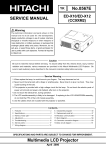
No. 0507E
YK
CP-X325W
SERVICE MANUAL
Caution
Be sure to read this manual before servicing. To assure safety from fire, electric shock, injury, harmful radiation
and materials, various measures are provided in this Hitachi liquid crystal projector. Be sure to read cautionary
items described in the manual to maintain safety before servicing.
Service Warning
1. When replace the lamp, to avoid burns to your fingers. The lamp becomes too hot.
2. Never touch the lamp bulb with a finger or anything else. Never drop it or give it a shock. They may cause
bursting of the bulb.
3. This projector is provided with a high voltage circuit for the lamp. Do not touch the electric parts of power unit
(main), when turn on the projector.
4. Do not touch the exhaust fan, during operation.
5. The LCD module ass'y is likely to be damaged. If replacing to the LCD module ass'y, do not hold the FPC of
the LCD module ass'y.
Contents
1.
2.
3.
4.
5.
6.
7.
Features
Specifications
Names of each part
Adjustment
Troubleshooting
Service points
Block diagram
2
2
3
5
11
17
22
8. Connector connection diagram
9. Wiring diagram
10.Basic circuit diagram
11.Disassembly diagram
12.Replacement parts list
13.Option parts list
SPECIFICATIONS AND PARTS ARE SUBJECT TO CHANGE FOR IMPROVEMENT.
Liquid Crystal Projector
October 2000 Digital Media Systems Division
23
24
27
55
57
58
CP-X325W
1. Features
High brightness, High resolution
Compact size, light weight for portability
RS-232C Communication
Complies with VESA DDC1/2B specifications
Auto-adjustment function
2. Specifications
Drive system
Liquid crystal
Panel size
panel
Number of pixels
TFT active matrix
Lamp
160W UHB
System
Video input
Level
0.9 inches
1024 (H) x 768 (V)
NTSC , 4.43NTSC , PAL , M-PAL , PAL60 , N-PAL or SECAM
Composite
Y/C
1.0Vp-p (75½ termination)
Y : 1.0Vp-p (75½ termination)
C : 0.286Vp-p (NTSC burst signal, 75½ termination)
0.3Vp-p (PAL/SECAM burst signal, 75½ termination)
Video signal
Analog RGB input
0.7Vp-p (75½ termination)
Sync signal
H/V separate
TTL level
Video signal
Analog RGB output
0.7Vp-p (75½ load output)
Sync signal
H/V separate
TTL level
RGB input
RGB output
Audio input
200mVrms, 47k½
Speaker output
1W + 1W (stereo)
Power supply
AC100~120V/2.8A , AC220~240V/1.2A
Power consumption
250W
Dimensions
298 (W) x 94.6 (H) x 228 (D) mm (expect the foot adjuster)
Weight
3.2kg (7.1lbs)
Temperature range
Operation
Storage
Accessories
Remote control transmitter
Battery
POWER cord
RGB cable
User's manual(with Safety Instructions)
: 0~35˚C
: -20~60˚C
–2–
1
2
3
1
1
Audio/Video cable
Mouse cable (PS/2)
Carrying bag
Handle
1
1
1
1
CP-X325W
3. Names of each part
Main unit
Speaker
Zoom Knob
Focus Ring
Handle Hook
Remote Control Sensor
Power Switch
Lens
Slide Lens door
Foot Adjuster
AC Inlet
(to the Power Cord)
Ventilation Openings
(Intake)
FRONT/LEFT VIEW OF THE PROJECTOR
Control Panel
STANDBY/ON Button
MUTE Button
INPUT Button
LAMP Indicator
TEMP Indicator
POWER Indicator
RESET Button
MENU Button
Foot Adjuster Button
Air Filter and Intake
(for the Cooling Fan)
Ventilation Openings
(exhaust)
Rear Foot Adjuster
REAR/RIGHT VIEW OF
THE PROJECTOR
S-VIDEO Terminal
VIDEO IN Terminal
AUDIO IN L Terminal
AUDIO IN R Terminal
1
AUDIO IN
AUDIO 1
IN
VIDEO IN
2 AUDIO OUT
RGB IN
Terminal Panel
(Refer below)
Remote Control Sensor
RGB IN 1 Terminal
RGB IN 2 Terminal
2
S-VIDEO IN
USB
RGB OUT
CONTROL
CONTROL Terminal
RGB OUT Terminal
USB Terminal
AUDIO IN 1 Terminal
AUDIO IN 2 Terminal
AUDIO OUT Terminal
TERMINAL PANEL
–3–
CP-X325W
Remote control transmitter
VIDEO button
STANDBY/ON button
VID
BLANK button
N
DBY/O
STAN
LAS
LASER button
EO
RGB button
ER
RG
DISK PAD
B
MOUSE / RIGHT button
K
BLAN
Used to click the right
mouse button.
Used to operate the
mouse shift function
and left click function.
POSITION button
AUTO button
RESET button
O
AUT
MENU button
POS
ME
MENU SELECT button
NU
ME
NU
,
,
button
EC
S EL
FR
IFY
MAGN
Used to click the right
mouse button.
T
RES
Used to click the left
mouse button.
,
ITION
ET
FREEZE button
E
EEZ
M
VOLU
OFF
E
MU
TE
TIM
ER
VOLUME button
MUTE button
TIMER button
Used to operate the
mouse shift function.
MAGNIFY button
REMOTE CONTROL TRANSMITTER
: These functions works when the mouse control function is activated. Remember, the POSITION, BLANK ON
and MENU ON functions disable the mouse control function.
WARNING
The laser pointer of the Remote control transmitter is used in place of a finger or rod.
Never look directly into the laser beam outlet or point the laser beam at other people.
The laser beam can cause vision problems.
CAUTION
LASER RADIATIONDO NOT STARE INTO BEAM
WAVE LENGTH: 650nm
MAX . OUTPUT: 1mW
CLASS 2 LASER PRODUCT
RADIAZIONI LASER
NON GUARDARE NEL RAGGIO LUCE
APPARECCHIO LASER DI CLASSE 2
RAYONNEMENT LASER
MANUFACTURED
NE PAS REGARDER DANS
LE FAISCEAU APPAREIL
A LASER DE CLASSE 2
LASER-STRAHLUNG
PLACE OF
MANUFACTURER:A
NICHT IN DEN STRAHL
BLICKEN LASER KLASSE2 MADE IN JAPAN
IEC60825-1:1993+A1:1997
NOTE: To prevent any malfunction;
• Do not give the Remote control transmitter any physical impact. Take care not to drop.
• Do not place the heavy objects on the Remote control transmitter.
• Do not wet the Remote control transmitter or place it on any wet object.
• Do not place the Remote control transmitter close to the cooling fan of the projector.
• Do not disassemble the Remote control transmitter in case of malfunction. Please bring it to the service station.
–4–
CP-X325W
4. Adjustment
4 - 1 Before adjusting
1. Before starting adjustment, warm up the projector
for about 10 min. (Blank white)
2. Set Zoom Wide to Max. and project an image a
distance of 40 inches.
3. Normalizing the video adjustment.
(Press the [MENU] button of the Remote control
transmitter to display the Setup menu, then press
the [RESET] button.)
*note : The setup menu is not displayed on with no
signal.
4. Perform all adjustments from the Adjustment menu.
Perform the following operations to display the
Adjustment menu.
a.Press the [MENU] button of the Remote control
transmitter (the Setup menu will appear).
b.Next, press the [RESET] button for 5 sec. or
more (the Adjustment menu will appear).
4 - 2 Ghost adjustment
Signals for internal adjustment
Adjustment procedure
1. Use DAC-P - GHOST-W: in the Adjustment menu
to adjust so that ghost is at a minimum.
(Set the adjustment value to 16, then raise the
value. When a ghost appears to the left of a vertical
line, reduce the value by 2 steps.)
30%
30%
0/255
bit
96/255
bit
4 - 3 Flicker adjustment (V.COM adjustment)
Signals for internal adjustment
Adjustment procedure
1. Make this adjustment after completing the
adjustment in 4-2 Ghost adjustment.
2. Use DAC-P - V.COM - R: in the Adjust menu to
adjust so that the flicker at the center of the screen
is less than the flicker at the periphery.
(When the flicker is about the same across the
whole screen, adjust so that the flicker at the center
of the screen is somewhat less than elsewhere.)
3. In the same way, use DAC-P - V.COM - G: in the
Adjustment menu to adjust the G color flicker.
4. In the same way, use DAC-P - V.COM - B: in the
Adjustment menu to adjust the B color flicker.
–5–
CP-X325W
4 - 4 PSIG adjustment (vertical stripe adjustment)
Signals for internal adjustment
Adjustment procedure
1. Make this adjustment after completing the
adjustment in 4-3 Flicker adjustment.
2. Use DAC-P - PSIG - G: in the Adjust menu to
adjust so that the vertical lines spaced every 6 dots
are as inconspicuous as possible.
4 - 5 White balance adjustment
9. Now, adjust the R and B colors.
10. Place the cursor on [A/D] - [SLIDE SHOW] in the
1. Perform these adjustments after the PSIG
adjustment described in Section 4-4.
2. First, adjust the G color.
3. Place the cursor on Slide Show in the Adjust
4.
5.
6.
7.
8.
menu [A/D], press the [ ] key three times to
display G monochrome and adjust the illuminance
at the center of the screen. Make a note of the
setting (here assumed to be A [lx]). Press the
MENU key to return.
Adjust Gamma 86% and G: in the Adjust menu so
that illuminance (Y) at the center of the screen is
adjusted as follows.
Y = A x 0.712 20 [lx]
Adjust Gamma, 43% and G: in the Adjust menu
so that illuminance (Y) at the center of the screen
is adjusted as follows.
Y = A x 0.155 5 [lx]
Adjust Gamma, 29% and G: in the Adjust menu
so that illuminance (Y) at the center of the screen
are adjusted as follows.
Y = A x 0.064 3 [lx]
Adjust Gamma, 14% and G: in the Adjust menu
so that illuminance (Y) at the center of the screen
is adjusted as follows.
Y = A x 0.014 2 [lx]
Adjust Gamma 0% and G: in the Adjust menu so
that illuminance (Y) at the center of the screen is
adjusted as follows.
Y = A x 0.005 0.5 [lx]
11.
12.
13.
14.
ADJUST menu and press the [ ] key once to
display a white screen. Then measure the color
coordinates at the center of the screen and take a
note of the setting (here assumed to be x1, y1).
Press the [MENU] key to return.
Adjust Gamma, 86%, R: and B: so that the color
coordinates (x, y) at the center of the screen take
on the following values.
x = (x1 - 0.005) 0.003
y = (y1 - 0.010) 0.005
Adjust Gamma, 43%, R: and B: so that the color
coordinates (x, y) at the center of the screen take
on the following values.
x = (x1 - 0.005) 0.003
y = (y1 - 0.015) 0.005
Adjust Gamma, 29%, R: and B: so that the color
coordinates (x, y) at the center of the screen take
on the following values.
x = (x1 - 0.010) 0.003
y = (y1 - 0.020) 0.005
Adjust Gamma, 14%, R: and B: so that the color
coordinates (x, y) at the center of the screen take
on the following values.
x = (x1 - 0.010) 0.003
y = (y1 - 0.025) 0.005
–6–
CP-X325W
Adjustment operations (reference)
Adjustment
point
0 14
29
43
Input signal (%)
86 100
29% operation
Adjustment
point
0 14
29
43
Input signal (%)
86 100
Adjustment point
29
43
Input signal (%)
Adjustment
point
0 14
29
43
Input signal (%)
86 100
0% operation
Brightness
Brightness
14% operation
0 14
Brightness
43% operation
Brightness
Brightness
86% operation
86 100
Adjustment
point
0 14
29
43
Input signal (%)
86 100
4 - 6 Color uniformity adjustment
Preparations
1. Perform these adjustments after the white balance
adjustment described in Section 4-5.
2. Make a color uniformity adjustment for the following
three tones.
· MIN tone (approx. 10% input signal)
6. To temporarily turn correction off, place the cursor
on ON in the Adjust Tone menu and press the [ ]
key. To turn it on again, place the cursor on OFF in
the Adjust Tone menu and press the [ ] key.
7. Although this adjustment can also be made using
internal signals, we will here use the [MENU
SELECT] key on the Remote control transmitter to
select the following two signals.
· Solid monochrome adjustment color (use G
· MID tone (approx. 50% input signal)
· MAX tone (approx. 75% input signal)
(Note that the MIN tone need not be adjusted when
there is no conspicuous color shading during a
black signal input.)
3. Place the cursor on the tone to be adjusted in the
color adjustment when a color differential meter
is used)
· Solid white (use for adjustment other than
Adjust menu and press the [ ] key. This displays
the Adjust Tone menu at the bottom of the screen.
Select the major adjustment lattice point No. and
color, then adjust them.
4. The major adjustment lattice point numbers (a total
of 17 points) corresponds to the major adjustment
lattice point positions in the diagram on the right.
The color uniformity of the entire screen can be
adjusted by adjusting the white balance for each of
the points starting in order from the low numbers.
5. Adjustment point No. 1 should not be adjusted,
because it controls the brightness of the entire
screen.
above)
8. Reset color shading correction before adjustment.
· When 3 tones and all colors are to be reset,
place the cursor on [C. UNIF]. in the Adjust
menu, press the [RESET] key and select
[DEFAULT].
· When only 1 tone is to be reset, place the cursor
on the tone to be reset press the [RESET] key
and select [DEFAULT].
· Single tone and monochrome resets cannot be
performed.
–7–
CP-X325W
Adjust menu
Major adjustment lattice point position
VIDEO
C. UNIF.
DAC-P
GAMMA
14
V/6
6
LEVEL
MIN
MID
Adjust Tone menu
10
R
0
G
0
B
H/3
Major adjustment lattice point No.
H/3
2
H/6
1
3
5
9
11
V/3
0
OFF
8
V/3
H/6
No. 1
16
4
MAX
ON
12
7
15
Adjustment procedure 1
(when a color differential meter is used)
1 First adjust [MIN] tone [G:].
Unless there is conspicuous black uniformity, there is no
need to adjust. (Go to step 7 if no adjustment is required.)
2 Select adjustment point [No. 2] [G:].
When the background is [G] monochrome, press
the [MENU SELECT] key on the Remote control
transmitter to change to solid white.
3 Adjust the color coordinates of adjustment point
[No. 1] and make a note of them.
Assume that they are x = x1, y = y1.
Note : When the CL-100 color and color difference
meter is used, the [Æ](delta) mode is
convenient. When adjustment point [No. 1]
color coordinate has been selected, set the
slide switch on the side to [Æ](delta) while
holding down the [F] button on the front
panel. The measurement shown after this
displays the deviation from measurement
point 1.
4 Now measure the color coordinates of measurement point [No. 2] and adjust [No. 2] and [G:] so
that the color coordinates are as follows.
y = y1 0.030 (adjust Y only)
Similarly, measure adjustment points [No. 3] to [No. 9]
and adjust their color coordinates starting in order from
the small number points.
5 Then measure the color coordinates for adjustment
point [No. 10] and adjust [No. 10] and [G:] so that
the color coordinates are as follows.
y = y1 0.050 (adjust Y only)
V/6
13
17
Similarly measure adjustment points [No. 11] to
[No. 17] and adjust their color coordinates starting
in order from the small number points.
6 This completes the adjustments required for [MIN].
Note : Since excessive correction may lead to a
correction data overflow during internal
calculations, use the following values for
reference.
[No. 2] to [No. 9] 40 or less
[No. 10] to [No. 17] 70 or less
7 Then adjust [MAX] tone [G].
Select [No. 2] [G:]. If the background is white solid,
press the [MENU SELECT] key on the Remote
control transmitter to change to [G] monochrome.
8 Measure the illuminance of measurement point
[No. 2] and [No. 3]. Temporarily set [No. 2] to
illuminance Y2 and [No. 3] to illuminance Y3 [lx].
9 Adjust the illuminance of measurement point [No. 2]
and [No. 3] to their average values. Thus illuminance
Y2' and Y3' of measurement points [No. 2] and [No. 3]
should be the following after adjustment.
Y2' = Y3' = (Y2 + Y3) ÷ 2 20 [lx]
10. Next, measure the illuminance of measurement
point [No. 10] and [No. 11].
Adjust the illuminance of measurement point [No. 10]
and [No. 11] to their average values. Thus
illuminance Y10' and Y11' of measurement points
[No. 10] and [No. 11] should be the following after
adjustment.
Y10' = Y11' = (Y10 + Y11) ÷ 2 20 [lx]
This completes [G] color adjustments.
–8–
CP-X325W
11. Then adjust [MAX] tone [R] and [B].
Select [No. 2] [B:] and press the [MENU SELECT]
key on the Remote control transmitter to change
to solid white.
12. Adjust the color coordinates of adjustment point
[No. 1] and make a note of them.
Assume that they are x = x1, y = y1.
13. Now measure the color coordinates of measurement point [No. 2] and adjust [No. 2] [R:] and [B:]
so that the color coordinates are as follows.
x = x1 0.005, y = y1 0.010
Similarly, measure adjustment points [No. 3] to
[No. 9] and adjust their color coordinates starting
in order from the small number points.
14. Then measure the color coordinates for adjustment point [No. 10] and adjust [No. 10] [R:] and
[B:] so that the color coordinates are as follows.
x = x1 0.005, y = y1 0.010
Similarly measure adjustment points [No. 11] to
[No. 17] and adjust their color coordinates starting
in order from the small number points.
15. This completes [MAX] tone adjustments.
16. Now make similar adjustments for [MID] tone.
(Note that [G] color adjustment tolerance is
10
[lx].)
Adjustment procedure 2 (visual inspection)
1. First adjust [MIN] tone [G:].
Unless there is conspicuous black shading, there
is no need to adjust. (Go to step 4 if no adjustment is required.)
2. Adjust only [G:] of measurement points [No. 2] to
[No. 17] in number order to minimize color shading.
(Use the deviation range information for each
measurement point given below as reference.)
3. This completes [MIN] tone adjustments.
4. Then adjust [MAX] tone [G] color.
5. Select [No. 2] [G:].
If the background is [G] monochrome, press the
[MENU SELECT] key on the Remote control
transmitter to change to solid white.
6. View measurement point [No. 2] and [No. 3].
Lower the [G] color intensity only of the color point
whose [G] color is more intense than measurement point [No. 1].
7. View measurement point [No. 10] and [No. 11].
Lower the [G] color intensity only of the color point
whose [G] color is more intense than measurement point [No. 1], and raise the intensity of the
point whose color intensity is lower than measurement point [No. 1].
8. This completes adjustments for [MAX] tone [G].
9. Now adjust the [MAX] tone for colors [R] and [B].
10. View measurement points [No. 2], [No. 3], [No. 10]
and [No. 11]. Adjust the [R] and [B] of each
measurement point so that they have the same
color as measurement point [No. 1].
Adjustment technique :
First, adjust [B:] of the point whose color is to be
adjusted so that it approximates that of [No. 1]. If
[R:] is low at this time, the image will have cyan
cast, in which case [R:] is increased. On the other
hand, if [R:] is excessive, the image will have a
magenta cast, in which case [R:] is decreased.
Overall, a cyan cast makes it easy to see color
shading.
11. Next, view measurement points [No. 4], [No. 5], [No. 12]
and [No. 13] and make similar adjustments.
12. Then adjust measurement points [No. 6], [No. 7], [No. 8],
[No. 9], [No. 14], [No. 15], [No. 16] and [No. 17]. This
completes the [MAX] tone adjustment.
13. Make similar [MID] adjustments as described in
steps 4 to 12 above.
–9–
CP-X325W
No. 2 deviation range
14
10
12
16
6
4
8
2
1
3 11
7
5
9
15
13
17
No. 4 deviation range
14
10
12
16
6
4
8
2
1
3 11
7
5
9
15
13
17
No. 6 deviation range
14
10
12
16
6
4
8
2
1
3 11
7
5
9
15
13
17
No. 14 deviation range
14
10
15
12
16
6
4
8
2
1
3 11
7
5
9
13
17
No. 10 deviation range
14
10
12
6
4
8
2
1
3 11
7
5
9
15
No. 3 deviation range
16
13
14
10
17
10
12
4
8
2
1
3 11
7
5
9
15
13
10
17
10
12
4
8
2
1
3 11
7
5
9
15
13
10
10
15
4
8
2
1
3 11
7
5
9
13
7
5
9
13
17
12
16
6
4
8
2
1
3 11
7
5
9
13
17
12
16
6
4
8
2
1
3 11
7
5
9
15
13
17
No. 16 deviation range
16
6
3 11
14
17
12
1
No. 8 deviation range
No. 15 deviation range
14
2
15
16
6
8
14
No. 7 deviation range
14
4
No. 5 deviation range
16
6
16
6
15
No. 12 deviation range
14
12
14
10
17
15
– 10 –
12
16
6
4
8
2
1
3 11
7
5
9
13
17
No. 11 deviation range
14
10
12
16
6
4
8
2
1
3 11
7
5
9
15
13
17
No. 13 deviation range
14
10
12
16
6
4
8
2
1
3 11
7
5
9
15
13
17
No. 9 deviation range
14
10
12
16
6
4
8
2
1
3 11
7
5
9
15
13
17
No. 17 deviation range
14
10
15
12
16
6
4
8
2
1
3 11
7
5
9
13
17
CP-X325W
5. Troubleshooting
Check points at trouble shooting
E302
ESPL
E806
S301
ESPR
E803
E807
E800
E808
P702
P502
P602
S302
E802
S303
E804
D302
E801
D301
E809
D303
S305
S304
S307
S306
EV01
S308
E101
S309
PWB ass'y Main
– 11 –
CP-X325W
Power can not be turned on
Are
voltage input
at pins 2 , 3 , 4 , 5 of
NO
E800 on the PWB ass’y
Main at standby
mode?
(TP46): +14V
YES
2
3 (TP47): +17V
4 (TP48): +6V
5 (TP49): +4.3V
Disconnect
TSW form Power unit
(circuit). And check
TSW short or
open?
Blinks
TSW
Short
Power unit (circuit)
What is the state of
TEMP indicator
D301?
Open
Fuse
on Power unit (circuit)
PWB ass’y SENSOR
DC FAN (EXHAUST)
Not light
What is the state of
LAMP indicator D302?
Blinks
Is the LAMP COVER
set?
Not light
NG
Set the LAMP COVER
OK
PWB ass’y Main
Is the LAMP
connection?
OK
H (More than 6V)
PWB ass’y Main
Measure
voltage at the 2
(TP73) of E809 on the
PWB ass’y Main.
L (OV)
Limit SW
(PWB ass’y SW)
– 12 –
NG
Set the LAMP again
CP-X325W
Lamp does not light
What is the state of
LAMP indicator
during operation?
Light
Change the lamp.
Does lamp light?
Light
Lamp
Not Light
Not light
Is the
voltage at L817
YES
on the PWB ass’y Main
fixed to "L" during
warming-up?
"L" = 0V
PWB ass’y Main
NO
Power unit (ballast)
Blinks
Connect
E302 (for PWB
ass’y SENSOR)
NO
Is
PWB ass’y
SENSOR surely
connected with PWB
ass’y Main by the
cable?
YES
DC FAN
(INTAKE A/B)
H (3.3V)
What is the state of
TEMP indicator?
Not light
Is the
voltage at L818
NO
on the PWB ass’y Main
set to "L" during
"L" = 0V
warming-up?
Measure sure
voltage at the 7 of I303
on the PWB ass’y
Main.
L (0V)
PWB ass’y
SENSOR
Infinity
Power unit (circuit)
YES
Power unit (ballast)
Measure
the resistancne of
TH950 on the PWB ass’y
SENSOR at
disconnecting
E302.
about 10k
PWB ass’y Main
– 13 –
PWB ass’y Main
CP-X325W
Picture is not displayed when
the RGB signal is input
Check at operating mode
Are signal
input at each pin of
E101 on the PWB
ass’y Main?
YES
1 , 30
4 , 27
7 , 24
10 , 21
11 , 20
Are
voltage input
at pins 2 , 3 , 4 , 5 of
E800 on the PWB
ass’y Main?
YES
NO
2
3
4
5
PWB ass’y Signal
: (TP1R) : R signal
: (TP1G) : G signal
: (TP1B) : B signal
: (TP1H) : H sync
: (TP1V) : V sync
NO
Power unit
(circuit)
(TP46): +14V
(TP47): +17V
(TP48): +6V
(TP49): +4.3V
PWB ass’y Main
LCD Panel
– 14 –
CP-X325W
Picture is not displayed when
the VIDEO Signal is input
Check at operating mode
Are
voltage input
at pins 2 , 3 , 4 , 5 of
E800 on the PWB
ass’y Main?
NO
YES
Power unit (circuit)
2
3
4
5
(TP46): +14V
(TP47): +17V
(TP48): +6V
(TP49): +4.3V
Are signal
input at these
pins of EV01 on the
PWB ass’y
Main?
NO
PWB ass’y Signal
YES
8 : S-CIN
10 : S-YIN
12 : Composite video
PWB ass’y Main
LCD module ass’y
– 15 –
CP-X325W
No sound
Check at operating mode
Are signal
input at these
pins of EV01 on the
PWB ass’y
Main?
NO
PWB ass’y Signal
YES
6 : Audio(L)
25 : Audio(R)
PWB ass’y Main
Speaker
Can not control to RS-232C
Check at operating mode
Pin No
RS232C
1
2
3
6
SEL0
7
RTS
9
10
GND
12
13
RDP
14
TDP
Are
the signals
input at each pin of
EV01 on the PWB ass’y
Main?
YES
NO
2 : TXD
1 : RXD
PWB ass’y Signal
PWB ass’y Main
– 16 –
CP-X325W
6. Service points
• Cautions when removing the PWB Ass'y Main
When removing the PWB Ass'y Main, there is danger of damaging the connector connecting cables and the PWB
Ass'y Signal.
1) Disconnect 11 cables and remove 6 screws.
PWB Ass'y Main
E302
E803
E806
E807
E804
E802
E801
E809
Remove 6 screws
2) Lift up the rearward of the PWB Ass'y Main to the front.
Lift up
FRONT
PWB Ass'y Main
REAR
3) Disconnect 2 cables lifting the PWB Ass'y Main.
Disconnect 2 cables
– 17 –
Disconnect the 2 board-to-board
connectors.
CP-X325W
• Before Replacing the LCD / Lens Prism
You should not replace separately the parts of the liquid crystal LCD / Lens Prism because it works properly only
when used together. Therefore, regarding these parts, you can either replace part , LCD / Lens Prism Ass'y, or
send the whole unit LCD / Lens Prism Ass'y back to HITACHI, where we will replace the malfunctioning part,
recondition the device and send it back to you. In that case please contact our distributor.
DISTRIBUTOR
HITACHI
G Panel
• Do not disassemble the unit
because replacement of
separate parts is not possible.
• For repairs of the product,
please contact our distributor.
Replacement of G Panel
Reconditioning
Return
• Air Filter Maintenance
The air filter should be cleaned as described below at intervals of approximately 100 hours.
1. Switch the projector power supply OFF, and remove the power cord from the power outlet.
2. Clean the air filter with a vacuum cleaner.
• Switch power OFF and remove the power cord from the power outlet before beginning maintenance
work. Please read the separate “SAFETY INSTRUCTIONS” thoroughly to ensure that maintenance is
performed correctly.
• Replace the air filter if contamination cannot be removed, or if it is damaged. Contact your dealer in
such case.(Option Air filter : MU01291)
• Do not use the equipment with the air filter removed.
• When the air filter is clogged with dust etc. the CHECK AIR FLOW message appears on the screen and
the power supply is switched OFF automatically to prevent the temperature rising inside the projector.
– 18 –
CP-X325W
• Loading the Battery
Install the AA batteries into the remote control.
1. Remove the battery cover.
Push the knob while lifting up the battery cover.
2. Loading the batteries.
Make sure the plus and minus poles are correctly
oriented.
3. Close the battery cover.
2
1
CAUTION
• Use only the specified batteries with this remote control. Also, do not mix new and old batteries.
This could cause in battery cracking or leakage, which could result in fire or personal injury.
• When loading the batteries, make sure the plus and minus terminals are correctly oriented as
indicated in the Remote control transmitter transmitter. Incorrect orientation could cause battery
cracking or leakage, which could result in personal injury or pollution of the surrounding environment.
• When you dispose the battery, you obey the law in the relative area or country.
• Keep the battery away from children and pets.
• When not to be used for an extended period, remove the batteries from the Remote control transmitter.
NOTE: Replace the batteries when remote control operation becomes difficult.
• Lamp
HIGH VOLTAGE
HIGH TEMPERATURE
HIGH PRESSURE
Contact your dealer before replacing the lamp.
(Option lamp: DT00331)
Before replacing the lamp, switch power OFF, remove the power cord from the power outlet, and wait
approximately 45 minutes until the lamp has cooled. The lamp may explode if handled at high temperatures.
• For disposal of used lamp, treat according to the instruction of community authorities.
• Since the lamp is made of glass, do not apply shock to it and do not scratch it.
• Also, do not use old lamp. This could also cause explosion of the lamp.
Lamp
• If it is probable that the lamp has exploded (explosive sound is heard),
disconnect the power plug from the power outlet and ask your dealer to
replace lamp.
The lamp is covered by front glass , but, in rare cases, the reflector and
the inside of the projector may be damaged by scattered broken pieces
Front
Reflector
glass
of glass, and broken pieces could cause injury when being handled.
• Do not use the projector with the lamp cover removed.
Lamp life
Projector lamps have a finite life. The image will become darker, and hues will become weaker, after a lamp has
been used for a long period of time.
Replace the lamp if the LAMP indicator is red, or the CHANGE THE LAMP message (see P.20 Table 8) appears
when the projector is switched ON.
NOTE: The LAMP is also red when the lamp unit reaches high temperature. Before replacing the lamp, switch
power OFF, wait approximately 20 minutes, and switch power ON again. If the LAMP indicator is still red,
replace the lamp.
– 19 –
CP-X325W
Replacing the lamp:
1. Switch the projector OFF, remove the power cord from the power outlet, and wait
at least 45 minutes for the unit to cool.
2. Prepare a new lamp.
3. Check that the projector has cooled sufficiently, and gently turn it upside down.
4. Loosen the two screws as shown in the diagram, and remove the lamp cover.
5. Loosen the three screws, and gently remove the lamp while holding the grips.
Touching the inside of the lamp case may result in uneven coloring.
6. Install the new lamp and tighten the three screws firmly. Also steadily push the
opposite side of the screwed lamp into the unit.
7. Replace the lamp cover in position and tighten the two screws firmly.
8. Gently turn the projector right-side up.
CAUTION
• Ensure that screws are tightened properly. Screws not
tightened fully may result in injury or accidents.
• Do not use the projector with the lamp cover removed.
Resetting the lamp timer:
Reset the lamp timer after replacing the lamp. When the lamp has been replaced after the LAMP indicator is red, or
the CHANGE THE LAMP message is displayed, complete the following operation within ten minutes of switching
power ON. The power will be turned off automatically in over 10 minutes.
1. Switch power ON, and press the TIMER button on the Remote control transmitter, or the RESET
button on
the control panel, for approximately three seconds. The ‘LAMP xxxx hr’ message will appear on the lamp timer
on the bottom of the screen.
2. Press the MENU button on the Remote control transmitter, or the RESET button on the control panel, while the
lamp timer is displayed. The ‘LAMP xxxx
3. Press the
0 CANCEL’ message will then appear.
and select 0, and wait until the timer display is cleared.
NOTE:
Do not reset the lamp timer without replacing the lamp. Reset the lamp timer always when replace the lamp. The
message functions will not operate properly if the lamp timer is not reset correctly.
1, 2
3
STANDBY/ON
BLANK
AUTO
MENU
LASER
FREEZE
VIDEO
RGB
POSITION
RESET
– 20 –
VOLUME
MUTE
1
MENU SELECT
MAGNIFY
OFF
TIMER
3
2
CP-X325W
Message table
On-screen display
The following messages are displayed on the screen.
"CHANGE THE LAMP"
"AFTER REPLACING LAMP, RESET Lamp has 1,700 hours on it and may need to be changed.
THE LAMP TIMER"
"CHANGE THE LAMP"
"AFTER REPLACING LAMP,
Lamp has 1,979 hours on it.
RESET THE LAMP TIMER"
See "Reset the lamp timer"
"THE POWER WILL TURN OFF
AFTER 20 Hr."
Blinking of "CHANGE THE LAMP"
"AFTER REPLACING LAMP,
When the lamp has 2,000 hours or more on it, the message will blink, and the
RESET THE LAMP TIMER"
power will turns off after 10 minutes.
"THE POWER WILL TURN OFF
AFTER 0 Hr."
"NO INPUT IS DETECTED"
Signal is not in.
"SYNC IS OUT OF RANGE"
The horizontal or vertical frequency of the input signal exceeds the range of
the projector, it cannot be displayed.
"CHECK THE AIR FLOW"
Please remove the obstruction before the suction port.
Indicator display
The ON indicator, LAMP indicator and TEMP indicator will light or blink in the following cases.
ON indicator LAMP indicator TEMP indicator
Lights orange
Meaning
Goes off
Goes off
Standby mode
Blinks green
Goes off
Goes off
Lights green
Goes off
Goes off
During operation
Blinks orange
Goes off
Goes off
During cooling down
Remedy
During warming up
Lights red
Lights red
Goes off
Lamp cannot light
Cool projector by power off for
20 minutes.
If the indicator is still lit, lamp
may be defective. Replace.
Lights red
Blinks red
Goes off
Lamp is not inserted or
Lamp cover is open
Securely insert the lamp or
shut the lamp door.
Lights red
Goes off
Blinks red
Cooling fan accidented or PWB
ass’y SENSOR accidented.
Replace fan, PWB ass’y SENSOR
or connect CNTH.
Lights red
Goes off
Lights red
Inside temperature becomes
high
Please remove the obstruction
before the suction port.
When inside temperature becomes high, to protect the projector, the lamp may be turned off and the lamp indicator
lights red, or the projector will be shut down and the all indicator display goes off.
– 21 –
Audio in
S-Video
Video
– 22 –
RS-232C
VOLUME
CONTROL
SIGNAL
SELECTOR
SIGNAL PWB
MOUSE
CTL
DDC
ACINPUT
USB
CTL
RGB
OUT
RGB
IN
RGB
IN
SP
SP
DCPOWER
SUPPRYPWB
IR RECEIVER
IR
RECEIVER
AUDIO_AMP
VIDEO
DECORDER
SAA7114
EEPROM
SUB CPU
SENSOR
TEMP
SENSOR
TEMP
1st_PLL
A/D,
AD9884A
SYNCSEP
RGB A/D
CLAMP
Flash ROM
S/P
LAMP POWER
SUPPRYPWB
DAC
P/S
DAC
P/S
PW164-10RK
Image_PROCESSOR
SRAM
MAIN PWB
CONTROL
PANEL
3rd_PLL
2nd_PLL
TIMING
GENERATOR
COLOR
UNIFORMITY
Lamp
DC POWER
REGURATO
OPTICAL
UNIT
FAN
FAN
FAN
FAN
FAN
PROJECTION
LENS
LCD
LCD LCD
0.9Type
PANEL
CP-X325W
7. Block diagram
CP-X325W
8. Connector connection diagram
S-VIDEO
AUDIO-IN
(VIDEO-L)
PWB
SIGNAL
PWB ass'y
ass'y SIGNAL
C.VIDEO
AUDIO-IN(VIDEO-R)
AUDIO-IN(RGB1)
AUDIO-IN(RGB2)
ESM2
16
17
18
19
20
21
22
23
24
25
26
27
28
29
30
1
2
3
4
5
6
7
8
9
10
11
12
13
14
15
RXD
TXD
MOUSE
REMOTE
GND
L.IN
GND
S.CIN
GND
S.YIN
GND
CVBSIN
GND
9V
9V
5V
5V
GND
YIN
GND
Cb/PbIN
GND
Cr/PrIN
GND
R.IN
GND
CLK.A
DATA.A
CS.A
NC
16
17
18
19
20
21
22
23
24
25
26
27
28
29
30
1
2
3
4
5
6
7
8
9
10
11
12
13
14
15
RGB.R
GND
GND
RGB.G
GND
GND
RGB.B
GND
GND
RGB.H-INV
RGB.V-INV
R1/R2
+5VST
+5VST
GND
GND
+5VST
+5VST
R1/R2
RGB.V-INV
RGB.H-INV
GND
GND
RGB.B
GND
GND
RGB.G
GND
GND
RGB.R
EV01
1
2
3
4
5
6
7
8
9
10
11
12
13
14
15
16
17
18
19
20
21
22
23
24
25
26
27
28
29
30
PWB ass'y MAIN
P502
P602
P702
AUDIO-OUT
ESM1
RGB1-IN
RGB2-IN
RGB-OUT
CONTROL
USB(MOUSE)
1 E101
2
3
4
5
6
7
8
9
10
11
12
13
14
15
16
17
18
19
20
21
22
23
24
25
26
27
28
29
30
1
2
3
4
5
6
7
8
9
10
11
12
13
14
15
16
17
18
19
20
21
22
23
24
25
26
27
28
29
30
31
32
PSIG
VSSGR
VSIG1
VSIG2
VSIG3
VSIG4
VSIG5
VSIG6
VSIG7
VSIG8
VSIG9
VSIG10
VSIG11
VSIG12
HVDD
RGT
HST
HCK2
HCK1
VSS
VSSGL
BLK
ENB
VCK
VST
OWN
HB
VB
PCG
VVDD
COM
TEST
E302(DF13-H)
1
2
CNTH
GND
OUT
E806
E806(DF13-H)
1
2
3
CNRM
GND
REMOTE
VCC
Thermistor
1
2
E950(DF13-2P)
1 PWB
2 ass'y
3 R/C
E801
( )
1
2
3
FAN1S
LCD-R
GND
FAN
(PANEL-R)
E802
( )
1
2
3
FAN2S
LCD-G
GND
FAN
(PANEL-G)
E803
( )
1
2
3
FAN3S
LCD-B
GND
FAN
(PANEL-B)
ESPL
(DF13-H)
1
2
LOUTLOUT+
LCD
PANEL
R/G/B
SPEAKER
ESPR
(DF13-H)
1
2
ROUTROUT+
SPEAKER
E809
1
2
CNLC
OUT
COVER
1
2
3
FAN4S
OUT
GND
E941
(DF13-H
1
2
PWB ass'y
COVER/LAMPSW
E804
FAN
(EXHAUST)
E807
3
1
2
3
4
5
6
7
8
9
10
11
12
13
14
CNPOW
120mm
FAN.GND
+14V
+17V
+6V
+4.3V
+4.3V
+4.3V
+4.3V
GND
GND
GND
GND
FAN-.ON/OFF
FAN-S_OUT
E808(PH3P)
1
2
3
CNBAR
LAMPON/OFF
GND
LAMP.MISS
E800
(PH14P)
R/C(REAR)
1 CN102
2
3
4
5
6
7
8
9
10
11
12
13
14
2 1
FAN5S
LAMP
GND
POWER UNIT
(CIRCUIT)
AC INLET
LAMP UNIT
ASS'Y
OUT+
OUT-
CN2
1
2
3
CN1
DCIN+
NC
DC IN-
POWER
UNIT
(BALLAST)
LAMP TEMPERATURE
SWITCH
– 23 –
CN101
1 (VH3P)
2
3
CNTS
TEMPOUT
TEMPRETURN
CN04(EH2P)
1
2
FAN
(LAMP)
Cross the CNPOW and
temperature switch lead.
Speaker (R)
Speaker (L)
CNPOW
Temperature
switch
temperature
switch lead
CN104
CN102
Power unit
CN103
ESPR
Upper view
(Speaker)
ESPL
Position of
rib of front bezel.
Position of
rib of front bezel.
CN101
Upper view (Power unit (circuit))
Speaker lead styling as shown chart, Use
claw of upper case not put in rib when front
bezel assembling.
– 24 –
Route the CNBAR lead through the
Ballast cover opening.
CNBAR is made not be to leave over
in the Ballast holder.
Upper case
Temperature
switch
PAS2
Clamp the CNBAR,
CNPOW and CNTH.
ESPL
Power unit
(Ballast)
Lead of Power
unit (Ballast)
CN2
To PWB ass'y Main E808
CNBAR
To PWB ass'y Main E800
CNPOW
To PWB ass'y Main E302
CNTH
E950
PWB ass'y sensor
Speaker (R)
ESPR
PWB ass'y Main
Upper view (Speaker)
CN104
CN101
CN102
Power unit
Side view (Power unit (Circuit / Ballast))
Projection lens side
Speaker (L)
CP-X325W
To PWB ass'y Main
Wiring of Speaker
9. Wiring diagram
Preparation for wiring of Power unit
TAPE1
Ballast cover
Folding part of the lead fixed not
to pass under the PWB ass’y Main.
PWB ass’y Main
Folding part
To PWB ass’y Main
E803,E807
FOOT HOLDER
Ballast cover
To Power unit (circuit)
CN104
Panel R
Sirocco fan
Hook the lead of Power unit
(Ballast) at the claw.
Do not put the lead on the
transformer of Power unit.
Panel B
Sirocco fan
Trans
CN1
Panel G
Sirocco fan
– 25 –
Lamp
Sirocco fan
Route the Sirocco
fan lead through
the opening.
Route the Sirocco
fan lead through
the inside of Duct
plate.
To Power unit
(Ballast)
Claw
CN101
Duct plate
Exhaust fan
Route the Temperature switch
lead through the opening in
the Ballast cover
Lead of Power unit (Ballast)
Temperature
switch
To PWB ass’y Main
E801,E802
Lamp lead
Route the earth lead
of Optical unit through
the inside of Duct plate
and Optical unit.
PAS1
Upper view (Removed PWB ass'y Main)
Insert a CN101
before the Optical
unit installation.
Route the Temperature switch
lead through the opening in
the Exhaust fan.
CP-X325W
With the purse lock, Clamp the
Ballast lead and Sirocco fan lead
through the Ballast cover.
CP-X325W
(1) Push in CNPOW,CNBAR and
CNTH between the Foot folder and
Power unit.
(2) You may insert which connector of
E803 and E807.
Cross the CNPOW and these lead.
These lead and not styling near the
projection lens side.
Styling not put in rib when
front bezel assembling.
CNPOW, CNBAR and CNTH
PWB ass’y
Remote control
Position of rib
of front bezel
To Speaker (L)
(1) Let CNPOW pass through
under the rib.
(2) Engage CNTH with a claw
of Power unit (circuit) holder.
Rib
CNPOW
To PWB ass’y
Power (circuit)
To PWB ass’y
Sensor
To PWB ass’y
Main
CNTH
Position of rib
of front bezel
PWB ass’y
Sensor
To Speaker (R)
CNTH
E950
CN2
E901
E302
E803 E807
E800
E808
CNRM
Panel R
Sirocco fan
– 26 –
Panel G
Sirocco fan
E806
ESPL E803
(Panel B) E807
(Lamp)
E302
Insert E800 and E808 before
PWB ass’y Main fixing
because the Optical unit side
of PWB ass’y Main.
ESPR
CNPOW
To Sirocco fan, Lamp
and Panel B.
E800
E808 CNBAR
To Sirocco fan, Lamp
and Panel B.
Exhaust fan
P502
P702
E804
You may insert
which connector of
E801 and E802 for
Sirocco fan.
E802(panel G)
E801(panel R)
P602
E809
PWB ass’y Main
The lead not put between the
PWB ass’y Main and Optical unit.
CNLC
PWB ass’y sensor
Upper view (Attached PWB ass'y Main)
E941
– 27 –
GND
CN1
3
1
CN2
2
1
3
C21
C50
C23
PC2
+
R32 C19
--
C18
R31 ZD1
PC1
L6
L4
R43
C99
--
+
2
D30
C98
PT
C2
6
7
5
2
1
Q1
3
D31
R44
R45
R46
R47
R48
R49
R50
10
8
C24
+
C1
R40
--
C7
C6
R12
R14
D3
R13
C5
R15
SSS
Q7
R37
R23 D13
Q6
D6
R36
4
HI C
C9
R4
R5
D7
Q2
Q3
9
L3
1
Ho
12
HB
3
D16
+
C2
C12
14
R41
--
D19
4
Q9
R39
R27 D25
Q8
R38
R25
Q5
C13
Q4
PC1
5
6
POWER UNIT ( BALLAST )
--
+
3
2
C16
C11
R21
D12
+
--
D4
C22
LAMP
E
D
C
B
A
10. Basic circuit diagram
E
D
C
B
L5
VR
R2
FB1
D2
C8
C10
D32
C3
L1
C14
D1
R1 TP
D18
D24
A
C15
CP
D29
R33
1
C20
PC2
C3
R35
R10
R11
R6
R7
R8
R9
R26
R28
R22
R24
DC370
CP-X325W
Parts with hatching are not mounted.
-+
Lo
R51
C4
R30
CP-X325W
A
A
CN101
1
CN101
2
CN101
3
RC
SW1
C108
R109
R111
C113
R110
C117
E
+
--
R112
--
B
CN1
D
GND
to POWER UNIT (CIRCUIT) 2/2
N
B
R102
R113
C116
C110
C109
C
G
D
+
--
C114
D104
C115
R114
D
TH101
– 28 –
R104
2
L104
CN1
2
CR101
1
6
R108
C106
C103
R116
4
Q101
7
R117 C119 C118
R115
5
8 IC101
3
C
A
R107
R103
C104
L102
C101
R101
R118
L101
RF101
D103
T101
+
R105
RC
R106
D101
SW1 F101
C107
CN1
1
C105
L
C102
B
H
E
E
POWER UNIT ( CIRCUIT ) 1/2
1
2
3
4
5
6
A
A
L301
T201
D302
R228
17V
R324
R317
--
L304
D303
C314 R318
D202
G
R320
Q306
R312
ZD202
R219
Q306
ZD301 D306
ZD302 D305
R322
R309
C313
R307
S1
+
--
Q302
R310
C307
IC301
C208
B1
CN102
13
FAN ON/OFF
R314
CN103
2
CN103
3
CN103
1
CN103
4
6V
FAN
GND
SIGNAL
C
R316
PC201
R304
--
--
R308
R306
R305
C306
+
ZD303 Q301
--
C309
+
+
H
C310
C304
PC202
--
R315
C306
R301
C301
C212
C209
R214
C204
C205
R217
C207
Q203
+
R302
R220
C203
B2
Q201
L303
D304
L202
D206 R226
D207
C202
--
S2
R215
PC202
R201
PC201
C315 R319
L305
IC201
ZD201
+
B
L-TEMP
14.5V
CN102
4
S3
L-TEMP
CN102
2
L302
D301
R225
R232
– 29 –
B
D
--
R323 R313
R222
CN104
2
+
Q204
--
D205
R213
D203
+
Q307
C316
R212
R218
C311
P2
C303
L201
R303
C211
D204
CN104
1
R325
S4
R224
PT
E
from POWER UNIT (CIRCUIT) 1/2
--
+
Q308 R321
C210
R211
B
D
+
P1
R231 R230 R229
C
C308
R205
A
CN102
3
C302
S5
CN102
5
CN102
6
CN102
7
CN102
8
4.3V
4.3V
4.3V
4.3V
CN102
14
SIGNAL
CN102
1
GND
CN102
9
GND
CN102
10
GND
CN102
11
GND
CN102
12
GND
D
E
E
POWER UNIT ( CIRCUIT ) 2/2
2
3
4
5
6
CP-X325W
1
CP-X325W
PWB ass'y SENSOR
PWB ass'y SWITCH
PWB ass'y REMOTE
– 30 –
CP-X325W
11. Disassembly diagram
M : Metric screw
T : Tapping screw
5
T3X12
27
T3X12
M3X8
27
23
25
3
M3X65
M3X65
1
7
9
8
6
2
M3X6
M3X6
– 55 –
CP-X325W
M3X8
M : Metric screw
T : Tapping screw
13
12
26
15
M3X10
M3X25
T3X12
T3X12
14
T3X12
T3X12
20
T3X12
26
11
M3X8
17
24
16
M3X8
T3X12
18
T3X10
M3X8
22
M3X8
M3X8
21
3
T2X5
19
10
4
– 56 –
CP-X325W
12. Replacement parts list
PRODUCT SAFETY NOTE : Components marked with a
have special characteristics important to safety. Before replacing any of there
components, read carefully, the PRODUCT SAFETY NOTICE of this Service Manual. Don't degrade the safety of the receiver through
improper servicing.
SYMBOL
PARTS
NO.
NO.
SYMBOL
PARTS
NO.
NO.
1
QD20542
2
QD20562
FRONT BEZEL ASS'Y
23
FH00203
TEMPERATURE SENSOR
LENS SHUTTER (Slide Lens door)
24
GS00452
DC FAN (INTAKE A)
3
4
QD20521
BOTTOM CASE ASS'Y
25
GS00531
DC FAN (EXHAUST)
QJ00901
ADJUST FOOT ASS'Y
26
GS00424
DC FAN (INTAKE B)
5
QD09761
UPPER CASE ASS'Y
27
GK00653
SPEAKER
6
PH08981
LAMP DOOR ASS'Y
7
PE00111
RUBBER FOOT
UX07155
LCD/LENS PRISM ASS'Y
8
PH09271
FILTER COVER ASS'Y
DT00331
C4 LAMP UNIT ASS'Y
9
MU01261
AIR FILTER
PV00281
HANDLE C4
10
NJ04663
PWB HOLDER
EA00561R
CPC32 CONNECTOR
DESCRIPTION
DESCRIPTION
11
NJ04901
BALAST HOLDER
EA01032R
CPC32 LOW CONNECTOR
12
ME02542
BALAST COVER
EV00631
POWER SUPPLY CORD(US TYPE)
13
PC04831
CONTROL BUTTON ASS'Y
EV00891
POWER SUPPLY CORD(EUROPE TYPE) W/CORE
14
UE07625
DICHROIC OPTICS UNIT
EV00861
POWER SUPPLY CORD(UK TYPE) W/CORE
15
JP04221B
PWB ASS'Y MAIN
EW06031
3 CONDUCTOR VIDEO CABLE
16
JP04232
PWB ASS'Y SIGNAL
EW05017
RGB-D CABLE(15PIN MALE TO 15PIN MALE)
17
JP04233
PWB ASS'Y REMOTE CONTROL
EW02753
PS/2-2 MOUSE CABLE W/CORE
18
JP04234
PWB ASS'Y LIMIT SWITCH
HL01451
REMOTE CONTROL UNIT
NX05741
CLEANING TOOL FOR DUST
19
JP04238
PWB ASS'Y SENSOR
20
HA00791
POWER UNIT (BALLAST)
21
HA00751
POWER UNIT (CIRCUIT)
22
2722448
FUSE 6.3A
– 57 –
CP-X325W
13. Option parts list
Caution
The cables (power cord/video cable, audio cable, RGB cable and other cables) must be used with
the core set to the projector side.
Use the cables which are included with the projector or specified.
No.
PARTS NO.
PARTS NAME
1
HL01571
Remote control transmitter Unit With laser pointer
2*
EW06471
PS/2 RMU-cable
3*
EW06472
ADB RMU-cable
4
EW06473
SERIAL RMU-cable
5
EW05941
USB (A-B) cable w/core
6
HL01581
Remote Mouse Receiver Ass'y
7
UK04661
Remote control transmitter Unit Ass'y (No.1+2+3+4+5+6)
8
EW06561
RS-232C cable Ass'y
*) When you use the PS/2 RMU-cable (No.2 above) or the ADB RMU-cable (No.3) ,the serial
RMU-cable (No.4) and the Remote Mouse Receiver Ass'y (No.6) must be used together.
– 58 –
CP-X325W
RS-232C communication
Caution The specified RS-232C cable has the user's manual with RS-232C command table.
(1) Turn off the projector and computer power supplies and connect with the RS-232C cable.
(2) Turn on the computer power supply and, after the computer has started up, turn on the projector power supply.
Projector
control jack
D-sub 15-pin shrink jack
5
1
10
6
15
11
Computer
1
2
3
4
5
SELO 6
RTS 7
8
9
GND 10
11
12
RD 13
TD 14
15
1
2
3
4
5
6
7
8
9
RS-232C jack
D-sub 9-pin
CD
RD
TD
DTR
GND
DSR
RTS
DTS
RI
2
1
6
3
7
4
8
Communications setting
19200bps, 8N1
1 Protocol
Consist of header (7 bytes) + command data (6 bytes).
2 Header
BE + EF + 03 + 06 + 00 + CRC_low + CRC_hige
CRC_low : Lower byte of CRC flag for command data.
CRC_high : Upper byte of CRC flag for command data.
3 Command data
Command data chart
byte_0
byte_1
byte_2
Action
low
byte_3
byte_4
Type
high
low
byte_5
Setting code
high
low
high
Action (byte_0 - 1)
Action
Classification
Content
1
SET
Change setting to desired value.
2
GET
Read projector internal setup value.
4
INCREMENT
Increment setup value by 1.
5
DECREMENT
Decrement setup value by 1.
6
EXECUTE
Run a command.
– 59 –
5
9
CP-X325W
Requesting projector status (Get command)
(1) Send the request code Header + Command data (‘02H’+‘00H’+ type (2 bytes) +‘00H’+‘00H’) from the computer
to the projector.
(2) The projector returns the response code ‘1DH’+ data (2 bytes) to the computer.
Changing the projector settings (Set command)
(1) Send the setting code Header + Command data (‘01H’+‘00H’+ type (2 bytes) + setting code (2 bytes)) from the
computer to the projector.
(2) The projector changes the setting based on the above setting code.
(3) The projector returns the response code ‘06H’ to the computer.
Using the projector default settings (Reset Command)
(1) The computer sends the default setting code Header + Command data (‘06H’+‘00H’+ type (2 bytes)
+‘00H’+‘00H’) to the projector.
(2) The projector changes the specified setting to the default value.
(3) The projector returns the response code ‘06H’ to the computer.
Increasing the projector setting value (Increment command)
(1) The computer sends the increment code Header + Command data (‘04H’+‘00H’+ type (2 bytes) +‘00H’+‘00H’)
to the projector.
(2) The projector increases the setting value on the above setting code.
(3) The projector returns the response code ‘06H’ to the computer.
Decreasing the projector setting value (Decrement command)
(1) The computer sends the decrement code Header + Command data (‘05H’+‘00H’+ type (2 bytes) +‘00H’ + ‘00H’)
to the projector.
(2) The projector decreases the setting value on the above setting code.
(3) The projector returns the response code ‘06H’ to the computer.
When a command sent by the projector cannot be understood by the computer
When the command sent by the projector cannot be understood, the error command ‘15H’ is returned by the
computer. Some times, the projector ignores RS-232C commands during other works. If the error command ‘15H’
is returned, please send the same command again.
When data sent by the projector cannot be practice
When the command sent by the projector cannot be practice, the the error code ‘1cH’ +‘xxxxH’ is returned.
When the data length is greater than indicated by the data length code, the projector will ignore the excess data
code.
Conversely, when the data length is shorter than indicated by the data length code, an error code will be returned
to the projector.
Caution
• Operation cannot be guaranteed when the projector receives an undefined command or data.
• Provide an interval of at least 40ms between the response code and any other code.
• The projector outputs test data when the power supply is switched ON, and when the lamp is lit.
Ignore this data.
• Commands are not accepted during warm-up.
– 60 –
CP-X325W
Command data chart
Names
Blank Color
Operation type
Set
Mirror
Freeze
Startup
Set
Set
Set
Language
Type
Setting code
03
06 00
3B D3
01 00
00 30
00 00
Orange
BE EF
03
06 00
AB D2
01 00
00 30
01 00
Green
BE EF
03
06 00
5B D2
01 00
00 30
02 00
Blue
BE EF
03
06 00
CB D3
01 00
00 30
03 00
Purple
BE EF
03
06 00
FB D1
01 00
00 30
04 00
White
BE EF
03
06 00
6B D0
01 00
00 30
05 00
Black
BE EF
03
06 00
9B D0
01 00
00 30
06 00
BE EF
03
06 00
08 D3
02 00
00 30
00 00
Normal
BE EF
03
06 00
C7 D2
01 00
01 30
00 00
H Inverse
BE EF
03
06 00
57 D3
01 00
01 30
01 00
V lnverse
BE EF
03
06 00
A7 D3
01 00
01 30
02 00
H&V Inverse
BE EF
03
06 00
37 D2
01 00
01 30
03 00
BE EF
03
06 00
F4 D2
02 00
01 30
00 00
Normal
BE EF
03
06 00
83 D2
01 00
02 30
00 00
Freeze
BE EF
03
06 00
13 D3
01 00
02 30
01 00
BE EF
03
06 00
B0 D2
02 00
02 30
00 00
Red
BE EF
03
06 00
7F D3
01 00
03 30
00 00
Orange
BE EF
03
06 00
EF D2
01 00
03 30
01 00
Green
BE EF
03
06 00
1F D2
01 00
03 30
02 00
BLUE
BE EF
03
06 00
8F D3
01 00
03 30
03 00
Purple
BE EF
03
06 00
BF D1
01 00
03 30
04 00
Transparent
BE EF
03
06 00
2F D0
01 00
03 30
05 00
Gray
BE EF
03
06 00
DF D0
01 00
03 30
06 00
Get
BE EF
03
06 00
4C D3
02 00
03 30
00 00
Turn ON
BE EF
03
06 00
0B D2
01 00
04 30
00 00
Turn OFF
BE EF
03
06 00
9B D3
01 00
04 30
01 00
Get
BE EF
03
06 00
38 D2
02 00
04 30
00 00
English
BE EF
03
06 00
F7 D3
01 00
05 30
00 00
Français
BE EF
03
06 00
67 D2
01 00
05 30
01 00
Deutsch
BE EF
03
06 00
97 D2
01 00
05 30
02 00
Español
BE EF
03
06 00
07 D3
01 00
05 30
03 00
Italiano
BE EF
03
06 00
37 D1
01 00
05 30
04 00
Norsk
BE EF
03
06 00
A7 D0
01 00
05 30
05 00
Nederlands
BE EF
03
06 00
57 D0
01 00
05 30
06 00
Português
BE EF
03
06 00
C7 D1
01 00
05 30
07 00
Japanese
BE EF
03
06 00
37 D4
01 00
05 30
08 00
Get
BE EF
03
06 00
C4 D3
02 00
05 30
00 00
Get
Menu Color
Action
BE EF
Get
Set
CRC
Red
Get
Set
Command data
Header
– 61 –
CP-X325W
Command data chart
Names
Operation type
Command data
Header
CRC
Action
Type
Setting code
Get
BE EF
03
06 00
7C D2
02 00
07 30
00 00
Increment
BE EF
03
06 00
1A D2
04 00
07 30
00 00
Decrement
BE EF
03
06 00
CB D3
05 00
07 30
00 00
Get
BE EF
03
06 00
C8 82
02 00
00 31
00 00
Increment
BE EF
03
06 00
AE 82
04 00
00 31
00 00
Decrement
BE EF
03
06 00
7F 83
05 00
00 31
00 00
Get
BE EF
03
06 00
08 86
02 00
10 31
00 00
Increment
BE EF
03
06 00
6E 86
04 00
10 31
00 00
Decrement
BE EF
03
06 00
BF 87
05 00
10 31
00 00
Brightness Reset
Execute
BE EF
03
06 00
58 D3
06 00
00 70
00 00
Contrast Reset
Execute
BE EF
03
06 00
A4 D2
06 00
01 70
00 00
V.Position Reset
Execute
BE EF
03
06 00
E0 D2
06 00
02 70
00 00
H.Position Reset
Execute
BE EF
03
06 00
IC D3
06 00
03 70
00 00
H.Size Reset
Execute
BE EF
03
06 00
68 D2
06 00
04 70
00 00
Color Balance R Reset
Execute
BE EF
03
06 00
94 D3
06 00
05 70
00 00
Color Balance B Reset
Execute
BE EF
03
06 00
D0 D3
06 00
06 70
00 00
Aspect Reset
Execute
BE EF
03
06 00
2C D2
06 00
07 70
00 00
Video Format Reset
Execute
BE EF
03
06 00
38 D1
06 00
08 70
00 00
Sharpness Reset
Execute
BE EF
03
06 00
C4 D0
06 00
09 70
00 00
Color Reset
Execute
BE EF
03
06 00
80 D0
06 00
0A 70
00 00
Tint Reset
Execute
BE EF
03
06 00
7C D1
06 00
0B 70
00 00
Keystone Reset
Execute
BE EF
03
06 00
08 D0
06 00
0C 70
00 00
Mirror Reset
Execute
BE EF
03
06 00
F4 D1
06 00
0D 70
00 00
Blank Color Reset
Execute
BE EF
03
06 00
B0 D1
06 00
0E 70
00 00
Startup Reset
Execute
BE EF
03
06 00
4C D0
06 00
0F 70
00 00
Auto
Execute
BE EF
03
06 00
91 D0
06 00
0A 20
00 00
off
BE EF
03
06 00
FB D8
01 00
20 30
00 00
on
BE EF
03
06 00
6B D9
01 00
20 30
01 00
BE EF
03
06 00
C8 D8
02 00
20 30
00 00
off
BE EF
03
06 00
07 D9
01 00
21 30
00 00
on
BE EF
03
06 00
97 D8
01 00
21 30
01 00
BE EF
03
06 00
34 D9
02 00
21 30
00 00
BE EF
03
06 00
D9 D8
02 00
20 60
00 00
Magnify
Timer
Auto off
Blank on/off
Set
Get
Set
Timer on/off
Get
Error Status
Get
(Example of Return)
00 00
01 00
(Normal) (Cover-error)
04 00
(Temp-error)
02 00
(Fan-error)
05 00
(Air flow-error)
– 62 –
03 00
(Lamp-error)
06 00
(Lamp-Time-over)
CP-X325W
Command data chart
Names
Operation type
Command data
Header
CRC
Power
Set
Set
Volume
Mute
Set
Brightness
Contrast
Color
Balance R
Color
Balance B
Keystone
Set
Aspect
Set
Setting code
BE EF
03
06 00
2A D3
01 00
00 60
00 00
ON
BE EF
03
06 00
BA D2
01 00
00 60
01 00
BE EF
03
06 00
19 D3
02 00
00 60
00 00
RGB
BE EF
03
06 00
FE D2
01 00
00 20
00 00
Video
BE EF
03
06 00
6E D3
01 00
00 20
01 00
SVideo
BE EF
03
06 00
9E D3
01 00
00 20
02 00
Get
BE EF
03
06 00
CD D2
02 00
00 20
00 00
Get
BE EF
03
06 00
31 D3
02 00
01 20
00 00
Increment
BE EF
03
06 00
57 D3
04 00
01 20
00 00
Decrement
BE EF
03
06 00
86 D2
05 00
01 20
00 00
Normal
BE EF
03
06 00
46 D3
01 00
02 20
00 00
Mute
BE EF
03
06 00
D6 D2
01 00
02 20
01 00
Get
BE EF
03
06 00
75 D3
02 00
02 20
00 00
Get
BE EF
03
06 00
89 D2
02 00
03 20
00 00
Increment
BE EF
03
06 00
EF D2
04 00
03 20
00 00
Decrement
BE EF
03
06 00
3E D3
05 00
03 20
00 00
Get
BE EF
03
06 00
FD D3
02 00
04 20
00 00
Increment
BE EF
03
06 00
9B D3
04 00
04 20
00 00
Decrement
BE EF
03
06 00
4A D2
05 00
04 20
00 00
Get
BE EF
03
06 00
01 D2
02 00
05 20
00 00
Increment
BE EF
03
06 00
67 D2
04 00
05 20
00 00
Decrement
BE EF
03
06 00
B6 D3
05 00
05 20
00 00
Get
BE EF
03
06 00
45 D2
02 00
06 20
00 00
Increment
BE EF
03
06 00
23 D2
04 00
06 20
00 00
Decrement
BE EF
03
06 00
F2 D3
05 00
06 20
00 00
Get
BE EF
03
06 00
B9 D3
02 00
07 20
00 00
Increment
BE EF
03
06 00
DF D3
04 00
07 20
00 00
Decrement
BE EF
03
06 00
0E D2
05 00
07 20
00 00
4:3
BE EF
03
06 00
9E D0
01 00
08 20
00 00
16:9
BE EF
03
06 00
0E D1
01 00
08 20
01 00
Small
BE EF
03
06 00
FE D1
01 00
08 20
02 00
BE EF
03
06 00
AD D0
02 00
08 20
00 00
Default
BE EF
03
06 00
62 D1
01 00
09 20
00 00
Bottom
BE EF
03
06 00
F2 D0
01 00
09 20
01 00
Top
BE EF
03
06 00
02 D0
01 00
09 20
02 00
BE EF
03
06 00
51 D1
02 00
09 20
00 00
Get
Display
Position at
16 : 9 or Small
Type
OFF
Get
Input Source
Action
Get
– 63 –
CP-X325W
Command data chart
Command data
Names
Operation type
V.Position
H.Position
H.Size
H.Phase
Sharpness
Color
Tint
Set
Video Format
Header
CRC
Action
Type
Setting code
Get
BE EF
03
06 00
0D 83
02 00
00 21
00 00
Increment
BE EF
03
06 00
6B 83
04 00
00 21
00 00
Decrement
BE EF
03
06 00
BA 82
05 00
00 21
00 00
Get
BE EF
03
06 00
F1 82
02 00
01 21
00 00
Increment
BE EF
03
06 00
97 82
04 00
01 21
00 00
Decrement
BE EF
03
06 00
46 83
05 00
01 21
00 00
Get
BE EF
03
06 00
B5 82
02 00
02 21
00 00
Increment
BE EF
03
06 00
D3 82
04 00
02 21
00 00
Decrement
BE EF
03
06 00
02 83
05 00
02 21
00 00
Get
BE EF
03
06 00
49 83
02 00
03 21
00 00
Increment
BE EF
03
06 00
2F 83
04 00
03 21
00 00
Decrement
BE EF
03
06 00
FE 82
05 00
03 21
00 00
Get
BE EF
03
06 00
F1 72
02 00
01 22
00 00
Increment
BE EF
03
06 00
97 72
04 00
01 22
00 00
Decrement
BE EF
03
06 00
46 73
05 00
01 22
00 00
Get
BE EF
03
06 00
B5 72
02 00
02 22
00 00
Increment
BE EF
03
06 00
D3 72
04 00
02 22
00 00
Decrement
BE EF
03
06 00
02 73
05 00
02 22
00 00
Get
BE EF
03
06 00
49 73
02 00
03 22
00 00
Increment
BE EF
03
06 00
2F 73
04 00
03 22
00 00
Decrement
BE EF
03
06 00
FE 72
05 00
03 22
00 00
Auto
BE EF
03
06 00
9E 75
01 00
00 22
0A 00
NTSC
BE EF
03
06 00
FE 71
01 00
00 22
04 00
PAL
BE EF
03
06 00
6E 70
01 00
00 22
05 00
SECAM
BE EF
03
06 00
6E 75
01 00
00 22
09 00
NTSC 4.43
BE EF
03
06 00
5E 72
01 00
00 22
02 00
M-PAL
BE EF
03
06 00
FE 74
01 00
00 22
08 00
N-PAL
BE EF
03
06 00
0E 71
01 00
00 22
07 00
BE EF
03
06 00
0D 73
02 00
00 22
00 00
Get
– 64 –
CP-X325W
MEMO
– 65 –
CP-X325W
QR46911
YK No. 0507E
Digital Media Systems Division
Printed in Japan (M)