1
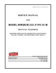
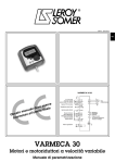
SSP-373-D-ADI2.01-650-541-ISSUE4.0
SERVICE MANUAL
FOR
MODEL SSP-373-D
STAINLESS STEEL ELEVATOR/
AUTOMATIC DIALING TELEPHONE
EQUIPPED WITH ADI2.01 FIMWARE
Serving the Telephone Industry Since 1930
Communication Equipment
& Engineering Company
519 W South Park Street
Okeechobee, FL 34972
Voice: 863-357-0798
Fax: 863-357-0006
ISSUE 4.0
IMPORTANT INFORMATION
FOR
CUSTOMER
Please fill in before you continue.
The following information is necessary when calling CEECO for assistance.
MODEL SSP-373-D EQUIPPED WITH ADI2.01
FIRMWARE.
MODEL NUMBER
SERIAL NUMBER
DATE MANUFACTURED
LOCATION INSTALLED
For us to better serve you, please have this information available when calling for
technical support.
CEECO
Communication Equipment and Engineering
Company
519 W South Park Street
Okeechobee, FL 34972
863-357-0798- telephone
863-357-0006- facsimile
[email protected]
www.ceeco.net
CEECO
Communication Equipment & Engineering Company
PROPRIETARY
2
ISSUE 4.0
TABLE OF CONTENTS
SECTION
PAGE
1.0
INTRODUCTION................................................................................................... 4
2.0
GENERAL DESCRIPTION .................................................................................. 4
3.0
PROGRAMMING .................................................................................................. 5
PROGRAMMING CONTINUED…..................................................................... 6
4.0
TESTING/OPERATION ....................................................................................... 7
5.0
RECOMMENDED TOOLS AND TEST EQUIPMENT .................................... 7
6.0
INSTALLATION NOTES AND ASSEMBLY INSTRUCTIONS ..................... 8
7.0
SPECIFICATIONS................................................................................................. 9
8.0
PARTS LIST ......................................................................................................... 10
9.0
FCC NOTICE........................................................................................................ 11
10.0 REPAIR AND RETURN INFORMATION....................................................... 12
11.0 WARRANTY POLICY ........................................................................................ 13
12.0 DIAGRAM............................................................................................................. 14
CEECO
Communication Equipment & Engineering Company
PROPRIETARY
3
ISSUE 4.0
1.0
INTRODUCTION
The practices in this manual provide installation and maintenance information for
the Model SSP-373-D Stainless Steel Elevator/Automatic Dialing Telephone.
The information in this manual is subject to change without notification.
For information not included in this manual, please call or write:
CEECO
Customer Service
519 W South Park Street
Okeechobee, FL 34972
863-357-0798- telephone
863-357-0006- facsimile
[email protected]
www.ceeco.net
2.0
GENERAL DESCRIPTION
2.1
The CEECO Model SSP-373-D Automatic Dialing Telephone is a
microprocessor-based, typical elevator style telephone, housed in a
rugged stainless steel case.
2.2
The telephone is designed to provide typical elevator type service. When
the handset is lifted one or two separate telephone numbers (depending on
user programming) of up to twenty five digits may be automatically
dialed. This telephone is also designed to deter fraudulent calling
attempts. The transmitter is muted during periods of dial tone to deter
fraud. Attempts to “flash-dial” will cause the microprocessor to go "on
hook" until the attempt has ended. It will then seize the line and dial any
programmed number(s).
2.3
Incoming calls are not allowed.
2.4
Programming is accomplished via an internally mounted DTMF keypad.
CEECO
Communication Equipment & Engineering Company
PROPRIETARY
4
ISSUE 4.0
3.0
PROGRAMMING
3.1
Remove the stainless steel assembly from the mounting box, if purchased
together. It will be necessary to use the security tool (sold separately as
CEECO part number 301-037) to remove the security screws. Connect
the telephone’s modular cord to a DTMF test set or a working telephone
line.
3.2
Looking at the rear of the phone, connect the programming keypad to
the white connector, which is hanging freely inside the phone. This
connector attaches to seven different colored wires and has a similar end,
which is already connected to the Printed Circuit Board.
3.3
Locate the two plastic mini-jumpers on the corner of the Printed Circuit
Board and move them to the "ON" position, as depicted on the last page
of this manual. Lift the handset and wait for dial tone.
3.4
Utilizing the programming keypad, enter # 9 7 on the keypad. This will
clear all field programmable memory.
NOTE: During programming it is essential to press the keys deliberately
and slowly. Missed or partial tones will result in improper programming.
3.5
If the phone must automatically dial a number, when the handset is
lifted, enter # 1 9 on the programming keypad, followed by the desired
number of up to twenty-five (25) digits in length. Once programmed, this
number will always dial, when the handset is lifted.
EXAMPLE: Entering #1918005551212 on the programming keypad will
cause the phone to automatically dial the number 1-800-555-1212, when
the handset is lifted.
•
Be sure to record your number in the Location #19 Table below for
future reference.
LOCATION #19 TABLE:
__ __ __ __ __ __ __ __ __ __ __ __ __ __ __ __ __ __ __ __ __ __ __ __ __
3.6
If the phone must automatically dial a second number, when the handset
Is lifted, enter # 2 0 on the programming keypad, followed by the desired
number of up to twenty-five (25) digits in length. In order for the phone
to dial the number stored in the #20 programming location, you must
select a “1” for Digit 1, under the #00 programming location (refer to next
section-3.7). You must also make selections for Digits 2 and 3
accordingly. Location #19 must be used in order to use Location #20.
CEECO
Communication Equipment & Engineering Company
PROPRIETARY
5
ISSUE 4.0
PROGRAMMING CONTINUED…
EXAMPLE: Entering #2019545875430 on the programming keypad will
cause the phone to automatically dial the number 1-954-587-5430, when
the handset is lifted.
•
Be sure to record your number in the Location #20 Table below for
future reference.
LOCATION #20 TABLE:
__ __ __ __ __ __ __ __ __ __ __ __ __ __ __ __ __ __ __ __ __ __ __ __ __
SCENARIO: Location #19 might be programmed to dial “9” for an
outside line. Location #20 might be programmed to dial 1-800-555-1212,
after the outside line is established. The programming sequence would be
#199#2018005551212, which is entered on the programming keypad.
3.7
Enter # 0 0 on the keypad. This accesses the telephone options
programming location. Now enter three digits, which you will select
from the options below, to customize the phone for the particular
installation.
Digit 1
0
Do not dial the number in location
1
Dial the number in location #20.
#20.
Digit 2
0
Wait for dial tone before dialing the number in location #20.
1
Wait for 1-9 seconds (depending on digit 3 below) before dialing
number in location #20.
Digit 3
1-9
Number of seconds to wait before dialing number in location #20.
•
Be sure to record your selections in the OPTIONS TABLE below for
future reference:
OPTIONS TABLE: # 0 0 __ __ __
3.8
Programming is now completed. Hang up the phone and return the two
plastic mini-jumpers to the “OFF” position as depicted on the last page
of this manual. The phone is now ready for Testing/Operation.
CEECO
Communication Equipment & Engineering Company
PROPRIETARY
6
ISSUE 4.0
4.0
5.0
TESTING/OPERATION
4.1
With the phone connected to a working phone line or a DTMF test set, lift
the handset. The telephone will wait for dial tone. When dial tone is
detected any number programmed as the first auto dial number (memory
location #19) will be dialed. The handset transmitter should be muted
(off) until dialing is complete. If the intended number does not dial out,
repeat sections 3.3, 3.5, and 3.8 only. If this does not solve the problem,
refer to section 10.2 please.
4.2
If there is a second number to auto dial (memory location #20), the phone
will either wait for the return of dial tone or wait the appropriate time
(depending on the programming selected under Location #00 Digit 2 and
Digit 3) and dial that second number. Remember that Digit 1, under
Location #00 must be set to “1” for Location #20 to be enabled. If the
second number does not dial out, repeat sections 3.3, 3.5, 3.6, 3.7 and 3.8.
If this does not solve the problem, please refer to section 10.2.
4.3
Normal phone operation should follow. Have the called party hang up.
Wait for the central office equipment to time out and return dial tone.
Shortly after dial tone is received, three tones should be heard. The phone
will open the line and remain in this condition until the handset is placed
on hook. The handset transmitter and receiver will be disabled during this
period.
4.4
Attempt to "hookswitch dial" by tapping quickly on the hookswitch. The
telephone should hang up, seize the telephone line and dial the
programmed auto dial number(s), when dial tone is received again.
RECOMMENDED TOOLS AND TEST EQUIPMENT
DTMF Test Set
Volt/Ohm Meter
1/4" Nut Driver
5/16" Nut Driver
Flat Blade Screw Driver
Security Tool 301-037
CEECO
Communication Equipment & Engineering Company
PROPRIETARY
7
ISSUE 4.0
6.0
INSTALLATION NOTES AND ASSEMBLY INSTRUCTIONS
6.1
The SSP-373-D is designed to be mounted inside any apparatus box with
dimensions of 6 7/8∀W x 9 3/4∀H x 3∀D or greater. CEECO part
number 371-011 is an apparatus box, which is well suited for this purpose.
Four mounting holes are required inside the box. If the holes are not
tapped, then self-tapping screws should be used when mounting the panel.
It is best to use the security screws, which do require tapped mounting
holes.
6.2
Mount the two mounting support brackets provided to the apparatus box
being used. Route the inside station wire and terminate to an RJ11C
modular jack or terminal block.
6.3
The use of a gas tube station protector is recommended. The station
ground should not exceed 50 ohms.
6.4
Plug the modular line cord from the telephone assembly into the RJ11C
modular jack or terminal block. Dress the line cable away from the
mounting holes. Install the telephone assembly by placing it into its
mounting box and securing it with the four security screws. The security
tool (CEECO part number 301-037 sold separately) will be needed.
*****WARNING*****
A.
Never install telephone wiring during a lightning storm.
B.
Never install telephone jacks in wet locations unless the jack
is specifically designed for wet locations.
C.
Never touch uninsulated telephone wires or terminals
unless the telephone line has been disconnected at the
network interface.
D.
Use caution when installing or modifying telephone lines.
CEECO
Communication Equipment & Engineering Company
PROPRIETARY
8
ISSUE 4.0
7.0
SPECIFICATIONS
INPUT POWER:
C.O. Line Powered
LOOP CURRENT:
23 mA min. to 80 mA max.
IMPEDANCE:
600 ohms
SIGNALING:
DTMF, 70ms tone, 50ms spacing
HEARING AID
COMPATIBILITY:
Meets EIA standards
ENVIRONMENTAL:
Temperature 0ºC to 50ºC
Humidity
20%-90% non-condensating
TELEPHONE PANEL:
Brushed 16-gauge stainless steel
DIMENSIONS:
6 7/8∀W x 9 3/4∀H x 3∀D
(handset on hook)
MOUNTING:
Vertical surface or enclosure mount
WEIGHT:
Approximately 4 lb.
RINGER EQUIVALENCY:
0.8A
FCC REGISTRATION NO.:
BW-88T7-13717-TE-T
UL LISTED NO.:
60F5
TYPE JACK:
RJ11C
CEECO
Communication Equipment & Engineering Company
PROPRIETARY
9
ISSUE 4.0
8.0
PARTS LIST
QUANTITY PART NUMBER
DESCRIPTION
1
371-008
Stainless steel panel
1
371-014
Handset with coiled cord & magnetic plate.
1
928-001
Strain relief bushing.
2
945-001
Magnetic reed switch assembly
1
341-018
Modular cord
2
371-009A
Mounting support bracket
1
650-541
MCRK-2 PCB Assembly
OPTIONAL
371-011
Mounting box
371-012
Frame assembly for mounting box
406-019
10-32 x ½” Security screw (4 req’d)
301-037
Security tool
CEECO
Communication Equipment & Engineering Company
PROPRIETARY
10
ISSUE 4.0
9.0
FCC NOTICE
9.1
FCC REGISTRATION AND REPAIR INFORMATION
Your new telephone has been registered with the Federal Communication
Commission (FCC) in accordance with Part 68 of its rules. The FCC
requires that you be advised of certain requirements involving the use of
this telephone.
9.2
CONNECTION AND USE WITH THE NATIONWIDE TELEPHONE
NETWORK.
The FCC requires that you connect this telephone to the Nationwide
Telephone Network through a registered jack provided by the Telephone
Company in your area. This jack is a modular outlet, which you can order
from your local telephone company.
9.3
NOTIFICATION TO THE TELEPHONE COMPANY
Before connecting this telephone, the FCC requires that you notify your
local telephone company business office. The number is in the front of
your phone book.
Tell them:
The "line" to which you will connect the telephone (that is, your phone
number), the telephone's FCC registration number and ringer equivalence
number. These numbers are listed in section 7.0
The FCC further requires that you notify your local telephone company
when permanently disconnecting this telephone.
CEECO
Communication Equipment & Engineering Company
PROPRIETARY
11
ISSUE 4.0
10.0 REPAIR AND RETURN INFORMATION
10.1
WARRANTY REPAIR
Any device returned requiring warranty service, repair or credit must be
accompanied with a "Return Material Authorization" (RMA) Form. It
must include: return shipping instructions, original purchase order number
and special marking instruction. A description of the trouble observed
must be attached to the defective unit. This information must be inside the
original shipping container.
10.2
DIRECT ALL INQUIRES TO:
CEECO
Repair Department
863-357-0798- telephone
863-357-0006- facsimile
[email protected]
www.ceeco.net
10.3
NON-WARRANTY REPAIR
CEECO will repair equipment out of warranty for a set charge plus parts.
The customer must pay the shipping costs both directions.
10.4
RETURN FOR CREDIT
Material may be returned for credit only with prior approval. Material
authorized for return is subject to a 20% restocking charge based on the
manufacturer’s list price. Return RMA must be requested no later than 30
days after original shipment.
10.5
EXCHANGE POLICY
If a replacement unit is required it will be shipped in the most expedient
manner consistent with the urgency of the situation. Please contact
"customer service" for instructions regarding exchange of modules or
printed circuit boards.
CEECO
Communication Equipment & Engineering Company
PROPRIETARY
12
ISSUE 4.0
11.0 WARRANTY POLICY
11.1
GENERAL
CEECO products are guaranteed to be free of defects in material and
workmanship for a period of 12 months from the date of original
shipment, if properly installed and maintained. This warranty is limited to
the value of material only.
CEECO will repair or replace any unit during this period if found to be
defective for reasons other than abuse and improper use or improper
installation. It is the buyer’s responsibility to return the defective unit to
the factory. CEECO will then repair or replace any defective parts and
return them to the buyer free of charge.
11.2
PRINTED CIRCUIT BOARDS
Printed circuit boards should not be field repaired. If a unit is found to be
faulty, replace it with another unit and return the faulty unit to CEECO for
repair. Modifications by anyone other than CEECO will void the
warranty.
CEECO
Communication Equipment & Engineering Company
PROPRIETARY
13
ISSUE 4.0
12.0 DIAGRAM
Locate the mini jumpers
on the corner of the PCB.
ON
F
OF
Move the mini jumpers to the
ON position BEFORE going
off-hook.
ON
F
OF
When programming is
completed, move the mini
jumpers to the OFF
position.
ON
F
OF
NOTE:
Do not leave the mini jumpers in the ON position;
this will decrease battery life.
CEECO
Communication Equipment & Engineering Company
PROPRIETARY
14