1
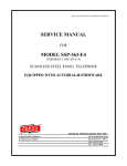
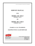
SSC OR BLC-303-1 CreditCardOnly-CST2.01-ISSUE 4.0
SERVICE MANUAL
FOR
MODEL SSC-303-I
OR
MODEL BLC-303-1
CREDIT CARD TELEPHONE
WITH INSERTION CARD READER
Equipped with CST 2.01 firmware.
Serving the Telephone Industry Since 1930
Communication Equipment
& Engineering Company
519 W South Park Street
Okeechobee, FL 34972
Voice: 863-357-0798
Fax: 863-357-0006
Issue 4.0
IMPORTANT INFORMATION
FOR
CUSTOMER
Please fill in before you continue.
The following information is necessary when calling CEECO for assistance.
MODEL NUMBER
MODEL SSC OR BLC-303-I EQUIPPED
WITH CST2.01 FIRMWARE
SERIAL NUMBER
DATE MANUFACTURED
LOCATION INSTALLED
For us to better serve you, please have this information available when calling for technical
support.
CEECO
Communication Equipment & Engineering Company
519 W South Park Street
Okeechobee, FL 34972
863-357-0798- telephone
863-357-0006- facsimile
[email protected]
www.ceeco.net
CEECO
Communication Equipment and Engineering Company
PROPRIETARY
2
Issue 4.0
TABLE OF CONTENTS
SECTION
PAGE
1.0
INTRODUCTION............................................................................................................... 4
2.0
GENERAL........................................................................................................................... 4
3.0
PROGRAMMING .............................................................................................................. 5
PROGRAMMING CONTINUED..................................................................................... 6
PROGRAMMING CONTINUED..................................................................................... 7
4.0
OPERATION ...................................................................................................................... 8
5.0
SPECIFICATIONS............................................................................................................. 9
6.0
PARTS LIST ..................................................................................................................... 10
7.0
RECOMMENDED TOOLS AND TEST EQUIPMENT .............................................. 10
8.0
INSTALLATION NOTES AND ASSEMBLY INSTRUCTIONS ............................... 11
9.0
TELEPHONE LINE WIRING DIAGRAM ................................................................... 12
10.0 FCC NOTICE.................................................................................................................... 13
11.0 REPAIR AND RETURN INFORMATION ................................................................... 14
12.0 WARRANTY POLICY .................................................................................................... 15
13.0 LOCATION OF PROGRAMMING JUMPERS........................................................... 16
CEECO
Communication Equipment and Engineering Company
PROPRIETARY
3
Issue 4.0
1.0
INTRODUCTION
The practices in this manual provide installation and maintenance information for the
CEECO Model SSC OR BLC-303-I Credit Card Telephone with Insertion Card Reader
and firmware CST2.01.
The information in this manual is subject to change without notification.
For information not included in this manual, please call or write:
CEECO
Customer Service
519 W South Park Street
Okeechobee, FL 34972
863-357-0798- telephone
863-357-0006- facsimile
[email protected]
www.ceeco.net
2.0
GENERAL
The CEECO Model 303-I Credit Card Telephone is a microprocessor-based, line
powered instrument designed to read the information encoded on the magnetic strip of
any ABA Track-2 credit card, and transmit the data via DTMF tones. This model is
compatible with most current credit cards using magnetic strip type cards.
NOTE: Before installing the phone, please read; Section 10.0 Installation Notes.
CEECO
Communication Equipment and Engineering Company
PROPRIETARY
4
Issue 4.0
3.0
PROGRAMMING
3.1
Using a security tool, remove the backplate and locate the Printed Circuit Board.
Locate the two plastic mini-jumpers on the Printed Circuit Board. With the phone
“on hook”, place the two mini-jumpers in the "ON" position, as depicted in the
diagram on the last page of this manual.
3.2
Lift the handset and dial # 9 7 on the keypad to clear all field programmable
memory.
3.3
If a local PBX is being used, enter # 1 9 on the keypad, followed by the PBX
access code (i.e. 9).
3.4
If call restrictions by the phone are necessary, use the keypad to enter the
allowable numbers as shown in the examples below. * is a wild card
representing/allowing any digit to be dialed. There are 10 memory locations
available for call restrictions (locations #70 - #79).
EXAMPLES:
(NOTE: "-" Shown for clarity only.)
# 7 0 0-***-***-**** (allows all 0-, 0+ calls)
Special Note: If call restrictions are in effect, the above example must be
programmed in order to use the credit cards.
# 7 1 * 1 1 (allows 911, 411, 611, etc.)
# 7 2 9 1 1 (allows 911 specifically)
# 7 3 1-* * *-5 5 5-1 2 1 2 (allows all long-distance information)
# 7 4 1-8 0 0-* * *-* * * * (allows all 800 numbers)
# 7 5 9 5 0-* * ** (allows all 950 exchange numbers)
# 7 6 * * *-* * * * (allows all seven-digit numbers)
And so on. The above examples are just examples of some typical dialing
patterns. The restrictions may be programmed as desired. A log if provided on
page 7, in section 3.8 for recording the programmed restrictions for future
reference.
CEECO
Communication Equipment and Engineering Company
PROPRIETARY
5
Issue 4.0
PROGRAMMING CONTINUED
3.5
Now, use the keypad to enter # 0 0 followed by the below string of eight (digits).
Notice that Digits 1, 2, and 5 choices to be made. Eight numbers must be entered
after entering #00 in order for the phone to function properly.
#00:
Digit 1:
0
No incoming calls allowed.
or
1
Incoming calls allowed.
Digit 2:
0
Call restrictions are in effect. (allowed numbers must be programmed in locations
#70-#79 or no calls will be permitted by the phone.)
or
1
No call restrictions.
Digit 3:
1
Digit 4:
0
Digit 5:
0
Send expiration date of Bank Cards mm/yr.
or
1
Do not send expiration date of Bank Cards.
Digit 6:
0
Digit 7:
0
Digit 8:
0
So, if #0010000000 was entered, the phone would be programmed to allow incoming
calls, perform call restrictions, and send the expiration dates of the cards.
CEECO
Communication Equipment and Engineering Company
PROPRIETARY
6
Issue 4.0
PROGRAMMING CONTINUED
3.6
When programming is completed, place the two mini-jumpers in the "OFF"
position and replace the handset.
3.7
To change a single memory location, place the phone on hook and place the two
mini-jumpers in the "ON" position. Lift the handset and enter # plus the two-digit
code for that memory location (i.e. #70, or #00, etc…), and enter the new
numbers. Hang the phone up and place the two mini-jumpers back in the "OFF"
position.
3.8
FREE CALL TABLE
CODE NUMBER
CODE NUMBER
#70
_-___-___-____
#75
_-___-___-____
#71
_-___-___-____
#76
_-___-___-____
#72
_-___-___-____
#77
_-___-___-____
#73
_-___-___-____
#78
_-___-___-____
#74
_-___-___-____
#79
_-___-___-____
CEECO
Communication Equipment and Engineering Company
PROPRIETARY
7
Issue 4.0
4.0
OPERATION
4.1
With the phone properly connected, lift the handset.
4.2
Two modes of operation may take place:
1.
Dial a free call; 911, 411 (only if number has been programmed /allowed
under call restrictions programming.
2.
Dial 0+ the number desired, wait for the tone, then insert/withdraw the
credit card. Upon verification of the credit card, a normal phone call
should proceed.
4.3
If a dialed number or a processed card is not permitted, the phone will emit a
series of three tones known as an error tone.
4.4
When the call is finished, return the handset to hang up the phone.
CEECO
Communication Equipment and Engineering Company
PROPRIETARY
8
Issue 4.0
5.0
SPECIFICATIONS
INPUT POWER
C.O. Line powered
LOOP CURRENT
23 mA min., 80 mA max.
IMPEDANCE
600 ohms
SIGNALING
DTMF, 70ms Tone, 70 ms Spacing
OUTPUT
-4 to -6 dBm
HEARING AID COMPATIBLE
Meets EIA standards
ENVIRONMENTAL
Temperature: 0°C to 50°C
Humidity: 20% to 90% non-condensing
RINGER EQUIVALENCY
0.8A
PROGRAMMING
Via unit keypad
TELEPHONE HOUSING
Brushed 16-gauge stainless steel
DIMENSIONS
7 1/2" Wide x 21" High x 6 1/2" Deep
(Handset on hook)
MOUNTING
Vertical surface mount
MEMORY RETENTION
Lithium battery, long life
FCC REGISTRATION
BW88T7-13823-TE-T
UL LISTED NO.
6OF5
TYPE JACK
RJ11C
CARD READER
Protocol
Capacity
Speed
Life
Insertion Type, Read Only
ABA Track-2, 1S02
40 characters
8-150 cm/sec
500,000 reads min.
CEECO
Communication Equipment and Engineering Company
PROPRIETARY
9
Issue 4.0
6.0
7.0
PARTS LIST
DESCRIPTION
Hookswitch Cradle
Tongue & Bracket Assembly
Handset w/Armored Cord
Network
Network Cable Assembly
Ringer
MCRK-2 PC Board Assembly
Chrome ANS Keypad
Keypad Cable
Modular Line Cord
#10-32 Security Screws (2 ea.)
Card Reader Assembly
Card Reader Cable
Instruction Card Kit
Number Window
Number Card
Backplate
Grommet
Modular Connector (RJ11C)
Handset Swivel
CTA Board
PART NO.
301-588
301-581
301-004
301-009
650-570
401-009
650-600
705-110
700-005
301-018
321-016
306-600
306-034
301-030
301-039
301-040
301-051
301-052
301-054
308-016
917-006
OPTIONAL:
Security Tool
301-037
RECOMMENDED TOOLS AND TEST EQUIPMENT
Volt/Ohm Meter
3/8∀ Nut Driver
Security Tool, CEECO Part Number 301-037
Flat Blade Screw Driver
DTMF Test Set
CEECO
Communication Equipment and Engineering Company
PROPRIETARY
10
Issue 4.0
8.0
INSTALLATION NOTES AND ASSEMBLY INSTRUCTIONS
8.1
Using a 301-037 security tool (sold separately), loosen (do not remove!) the
large outer cover locking screw, located at the front bottom center of the
telephone housing. Remove the two security screws located on the sides of the
telephone housing.
8.2
The security tool is for a standard 5/32" button head screw generally used on the
framework of the phone booths.
8.3
Separate the cover assembly from the backplate assembly.
8.4
The backplate assembly may be installed on any suitable vertical surface or any
standard payphone backboard.
8.5
Run the telephone line wire through the backplate assembly and terminate
on the RJ11C modular jack on the backplate, as depicted in the diagram
on the following page of this manual. The CEECO-provided modular jack must
be used, as it contains required over-voltage protection.
8.6
The use of a gas tube station protector is recommended. The station ground
should not exceed 50 ohms.
8.7
Plug the modular line cord from the telephone into the RJ11C modular jack.
8.8
Dress the line cord away from the security screw and install the cover assembly
by inserting the tabs into the slots on top of the backplate.
8.9
Secure the cover assembly by replacing the two security screws on the sides and
tightening the outer cover locking screw on the front.
*****WARNING*****
A.
Never install telephone wiring during a lightning storm.
B.
Never install telephone jacks in wet locations unless the jack is specifically
designed for wet locations.
C.
Never touch uninsulated telephone wires or terminals unless the telephone
line has been disconnected at the network interface.
D.
Use caution when installing or modifying telephone lines.
CEECO
Communication Equipment and Engineering Company
PROPRIETARY
11
Issue 4.0
9.0
Telephone Line Wiring Diagram
CEECO
Communication Equipment and Engineering Company
PROPRIETARY
12
Issue 4.0
10.0 FCC NOTICE
10.1
FCC REGISTRATION AND REPAIR INFORMATION
Your new telephone has been registered with the Federal Communication
Commission (FCC) in accordance with Part 68 of its rules. The FCC requires that
you be advised of certain requirements involving the use of this telephone.
10.2
CONNECTION AND USE WITH THE NATIONWIDE TELEPHONE
NETWORK.
The FCC requires that you connect this telephone to the Nationwide Telephone
Network through a registered jack provided by the telephone company in your
area. This jack is a modular outlet which you can order from your local telephone
company.
10.3
NOTIFICATION TO THE TELEPHONE COMPANY
Before connecting this telephone, the FCC requires that you notify your local
telephone company business office. The number is in the front of your phone
book.
Tell them:
The "line" to which you will connect the telephone (that is, your phone number),
the telephone's FCC registration number and ringer equivalence number. These
numbers are listed in section 7.0
The FCC further requires that you notify your local telephone company when
permanently disconnecting this telephone.
CEECO
Communication Equipment and Engineering Company
PROPRIETARY
13
Issue 4.0
11.0 REPAIR AND RETURN INFORMATION
11.1
WARRANTY REPAIR
Any device returned requiring warranty service; repair or credit must be
accompanied with a "Return Material Authorization" (RMA) FORM. It must
include: return shipping instructions, original purchase order number and special
marking instruction. A description of the trouble observed must be attached to
the defective unit. This information must be inside the shipping container.
11.2
DIRECT ALL INQUIRES TO:
CEECO
Repair Department
863-357-0798- telephone
863-357-0006- facsimile
[email protected]
www.ceeco.net
11.3
NON-WARRANTY REPAIR
CEECO will repair equipment out of warranty for a set charge plus parts. The
customer must pay the shipping costs for both directions.
11.4
RETURN FOR CREDIT
Material may be returned for credit only with prior approval. Material authorized
for return is subject to a 20% restocking charge based on the manufacturer’s list
price. Return Material Authorization must be requested no later than 30 days
after original shipment.
11.5
EXCHANGE POLICY
If a replacement unit is required it will be shipped in the most expedient manner
consistent with the urgency of the situation. Please contact "Customer Service"
for instructions regarding exchange of modules or printed circuit boards.
CEECO
Communication Equipment and Engineering Company
PROPRIETARY
14
Issue 4.0
12.0 WARRANTY POLICY
12.1
GENERAL
CEECO products are guaranteed to be free of defects in material and
workmanship for a period of 365 days from the date of original purchase.
CEECO’s obligation under this warranty is limited to repair or replacement of any
part found to be defective by CEECO. Under no circumstances shall CEECO be
liable for loss, damage, cost of repair, or consequential damages of any kind
which have been caused by neglect, abuse, acts of GOD or improper of
equipment.
12.2
PRINTED CIRCUIT BOARDS
Printed circuit boards should not be field repaired. If a unit is found to be faulty,
replace it with another unit and return the faulty unit to CEECO for repair.
Modifications by anyone other than CEECO will void the warranty.
CEECO
Communication Equipment and Engineering Company
PROPRIETARY
15
Issue 4.0
13.0 LOCATION OF PROGRAMMING JUMPERS
Locate the mini jumpers
on the corner of the PCB.
ON
F
OF
Move the mini jumpers to
the ON position BEFORE
going off-hook.
When programming is
completed, move the mini
jumpers to the OFF
position.
ON
F
OF
ON
F
OF
NOTE:
Do not leave the mini jumpers in the ON position,
this will decrease battery life.
CEECO
Communication Equipment and Engineering Company
PROPRIETARY
16