1
SERVICE MANUAL
FILE NO.
1
2
3
4
0409_C_S
OUTDOOR MODEL No.
PRODUCT CODE No.
APPLICABLE INDOOR MODEL No.
V / ø / Hz
SPW-CR363GVH8
85401464
SPW - KR · ASR · SR· UR · FR· FMR · SLR
93GH56
SPW-CR483GVH8
85401465
SPW - XR · KR · ASR · SR· UR · FR· FMR · SLR 123GH56
SPW-CR703GVH8
85401468
SPW - XR · KR · TR · SR· UR · FR· FMR · SLR
183GH56
SPW-CR903GVH8
85401469
SPW - XR · TR · SR· UR · DR · FR· FMR · SLR
253GH56
SPW-CR363GV8
85401466
SPW - XR · TR · UR · DR
363GH56
SPW-CR483GV8
85401467
SPW - XR · TR · UR · DR
483GH56
SPW-CR703GV8
85401470
SPW-CR903GV8
85401471
85464849163001
OUTDOOR
380 - 415 / 3 ø / 50
INDOOR
220 - 240 / 1 ø / 50
REFERENCE NO. SM830063
: http://splitoff.ru/tehn-doc.html
Important
Please Read Before Starting
When
Installing
……………………………………………………………………
This air conditioning system meets strict safety and
operating standards. As the installer or service person, it
is an important part of your job to install or service the
system so it operates safely and efficiently.
…In a Room
Properly insulate any tubing run inside a room to prevent
“sweating” that can cause dripping and water damage to
walls and floors.
For safe installation and trouble-free operation, you
must :
ⓦ Carefully read this instruction booklet before beginning.
…In Moist or Uneven Locations
Use a raised concrete pad or concrete blocks to provide a
solid, level foundation for the outdoor unit. This prevents
water damage and abnormal vibration.
ⓦ Follow each installation or repair step exactly as shown.
…In an area with High Winds
ⓦ Observe all local, state, and national electrical codes.
Securely anchor the outdoor unit down with bolts and a
metal frame. Provide a suitable air baffle.
ⓦ Pay close attention to all warning and caution notices
given in this manual.
…In a Snowy Area (for Heat Pump-type Systems)
This symbol refers to a
hazard or unsafe practice
which can result in severe
personal injury or death.
CAUTION
Install the outdoor unit on a raised platform that is higher
than drifting snow. Provide snow vents.
When
Connecting Refrigerant Tubing
……………………………………………………………………
• Ventilate the room well, in the event that refrigerant gas
leaks during the installation. Be careful not to allow
contact of the refrigerant gas with a flame as this will
cause the generation of poisonous gas.
This symbol refers to a
hazard or unsafe practice
which can result in personal
injury or product or property
damage.
• Keep all tubing runs as short as possible.
If Necessary, Get Help
• Use the flare method for connecting tubing.
These instructions are all you need for most installation
sites and maintenance conditions. If you require help for a
special problem, contact our sales/service outlet or your
certified dealer for additional instructions.
• Apply refrigerant lubricant to the matching surfaces of
the flare and union tubes before connecting them, then
tighten the nut with a torque wrench for a leak-free
connection.
In Case of Improper Installation
• Check carefully for leaks before starting the test run.
The manufacturer shall in no way be responsible for
improper installation or maintenance service, including
failure to follow the instructions in this document.
NOTE
Depending on the system type, liquid and gas lines may
be either narrow or wide. Therefore, to avoid confusion the
refrigerant tubing for your particular model is specified as
either “narrow” or “wide” rather than as “liquid” or “gas”.
SPECIAL PRECAUTIONS
When
Wiring
……………………………………………………………………
ELECTRICAL SHOCK CAN CAUSE
SEVERE PERSONAL INJURY OR DEATH.
ONLY A QUALIFIED, EXPERIENCED
ELECTRICIAN SHOULD ATTEMPT TO
WIRE THIS SYSTEM.
When Servicing
……………………………………………………………………
• Turn the power OFF at the main power box (mains)
before opening the unit to check or repair electrical
parts and wiring.
• Do not supply power to the unit until all wiring and
tubing are completed or reconnected and checked.
• Keep your fingers and clothing away from any moving
parts.
• Highly dangerous electrical voltages are used in this
system. Carefully refer to the wiring diagram and these
instructions when wiring. Improper connections and
inadequate grounding can cause accidental injury or
death.
• Clean up the site when installation is finished. Check
that no metal scraps or bits of wiring have been left
inside the unit.
• Ground the unit following local electrical codes.
CAUTION
• Connect all wiring tightly. Loose wiring may cause
overheating at connection points and a possible fire
hazard.
When
Transporting
……………………………………………………………………
• Ventilate any enclosed areas when installing or testing
the refrigeration system. Contact of refrigerant gas with
fire or heat can produce poisonous gas.
Be careful when picking up and moving the indoor and
outdoor units. Get a partner to help, and bend your knees
when lifting to reduce strain on your back. Sharp edges or
thin aluminum fins on the air conditioner can cut your
fingers.
• Confirm after installation that no refrigerant gas is
leaking. If the gas comes in contact with a burning
stove, gas water heater, electric room heater or other
heat source, it can cause the generation of poisonous
gas.
i
: http://splitoff.ru/tehn-doc.html
Check of Density Limit
Important
The room in which the air conditioner is to be
installed requires a design that in the event of
refrigerant gas leaking out, its density will not
exceed a set limit.
NOTE
(1)
The refrigerant R-407C which is used in the air conditioner is safe, without the toxicity or combustibility of
ammonia, and is not restricted by laws to be imposed
which protect the ozone layer. However, since it contains
more than air, it poses the risk of suffocation if its density
should rise excessively. Suffocation from leakage of
R-407C is almost non-existent. With the recent increase
in the number of high density buildings, however, the
installation of multi air conditioner systems is on the
increase because of the need for effective use of floor
space, individual control, energy conservation by
curtailing heat and carrying power etc.
Most importantly, the multi air conditioner system is able
to replenish a large amount of refrigerant compared with
conventional individual air conditioners. If a single unit of
the multi air conditioner system is to be installed in a
small room, select a suitable model and installation
procedure so that if the refrigerant accidentally leaks out,
its density does not reach the limit (and in the event of an
emergency, measures can be made before injury can
occur).
In a room where the density may exceed the limit, create
an opening with adjacent rooms, or install mechanical
ventilation combined with a gas leak detection device.
The density is as given below.
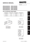
2 : The standards for minimum room
volume are as follows.
No partition (shaded portion)
0001_M_I
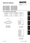
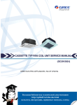
(2)
When there is an effective opening with the
adjacent room for ventilation of leaking refrigerant
gas (opening without a door, or an opening 0.15%
or larger than the respective floor spaces at the top
or bottom of the door).
Outdoor unit
Refrigerant tubing
Indoor unit
0002_M_I
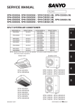
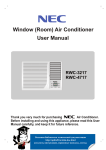
(3)
If an indoor unit is installed in each partitioned room
and the refrigerant tubing is interconnected, the
smallest room of course becomes the object. But
when a mechanical ventilation is installed
interlocked with a gas leakage detector in the
smallest room where the density limit is exceeded,
the volume of the next smallest room becomes the
object.
Refrigerant tubing
Total amount of refrigerant (kg)
Outdoor unit
3
Min. volume of the indoor unit installed room (m )
> Density limit (kg/m3)
Very
small
room
Indoor unit
The density limit of R-407C which is used in multi
air conditioners is 0.3 kg/m3.
Small
room
Medium
room
Large room
Mechanical ventilation device - Gas leak detector
0003_M_I
1 : If there are 2 or more refrigerating
systems in a single refrigerating
device, the amount of refrigerant
should be as charged in each
independent device.
NOTE
Outdoor unit
e.g.,
charged amount (15 kg)
Min. indoor floor area
(when the ceiling is 2.7 m high)
e.g., charged
amount (10 kg)
Room A Room B Room C Room D Room E Room F
Indoor unit
0803_M_I
For the amount of charge in this example:
The possible amount of leaked refrigerant gas in
rooms A, B and C is 10 kg.
The possible amount of leaked refrigerant gas in
rooms D, E and F is 15 kg.
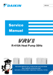
3 : The minimum indoor floor space compared with the amount of refrigerant is
roughly as follows.
(When the ceiling is 2.7 m high)
m2
50
m3
135
45
121.5
40
108
35
94.5
30
25
20
15
Min. indoor volume
NOTE
Range below the
density limit of
0.3 kg/m3
(Countermeasures
not needed)
81.0
67.5
Range above the
density limit of
0.3 kg/m3
(Countermeasures
needed)
54.0
40.5
10
27.0
5
13.5
10
20
30
Total amount of refrigerant
40 kg
1169_M_I
ii
: http://splitoff.ru/tehn-doc.html
Contents
Page
Please Read Before Starting Important ....................................................... i
Check of Limit Density Important ................................................................ii
Line Up .........................................................................................................iv
Section 1 :
ECO MULTI SYSTEM Unit Specifications ........................ I - 1
1.
2.
3.
4.
5.
6.
7.
8.
9.
10.
11.
Section 2 :
Processes and Functions ................................................ II - 1
1.
2.
3.
4.
5.
6.
7.
8.
9.
10.
11.
12.
13.
14.
15.
16.
17.
18.
19.
Section 3 :
Compressor Control ............................................................................................ II Reverse Cycle Defrosting ................................................................................... II Reverse Cycle Starting Control ........................................................................... II Outdoor Fan Control ........................................................................................... II 4-way Valve Switching Control............................................................................ II Save Valve Control ............................................................................................. II Outdoor Electronic Control Valve ........................................................................ II Liquid Valve Control ............................................................................................ II Room Temperature Control ................................................................................ II Auto. Mode for Automatic Heating/Cooling Switching ........................................ II Heating Preparations .......................................................................................... II Dehumidifying Control ......................................................................................... II Automatic Fan Speed Control ............................................................................. II Auto-flap Control ................................................................................................. II Drain Pump Control ............................................................................................ II Indoor Electronic Control Valve ........................................................................... II Dischage Temperature Control (Only for U, D Type) ......................................... II Automatic Restart Function after Power Failure................................................. II Filter Sign ............................................................................................................ II -
2
6
7
7
7
7
8
8
9
10
11
12
12
13
14
14
15
15
15
Service Procedures ......................................................... III - 1
1.
2.
3.
4.
5.
6.
7.
8.
9.
10.
11.
12.
13.
Section 4 :
Outdoor Unit ....................................................................................................... I - 3
4-way Air Discharge Semi-concealed Type ........................................................I - 19
2-way Air Discharge Semi-concealed Type ........................................................I - 34
1-way Air Discharge Semi-concealed Type ........................................................I - 48
Wall Mounted Type ............................................................................................. I - 56
Ceiling Mounted Type ......................................................................................... I - 66
Concealed Duct Type ......................................................................................... I - 78
Concealed Duct High Static Pressure Type ........................................................I - 97
Floor-Standing Type (F Type) ............................................................................. I - 107
Concealed Floor-Standing Type (FM Type) ........................................................I - 119
1-way Air Discharge Semi-concealed-Slim Type (SL Type) .............................. I - 135
Troubleshooting .................................................................................................. III - 2
Sensor and Solenoid Layout Diagram ................................................................ III - 37
Thermistor Characteristic Curve ......................................................................... III - 46
Test Run ............................................................................................................. III - 47
PCBs illustrations ................................................................................................ III - 50
Check of Density Limit ........................................................................................ III - 53
Cautions for New Refrigerant R407C .................................................................. III - 54
Compressor Failure ............................................................................................ III - 56
Operation Procedure for Replacing the Compressor ......................................... III - 57
Malfunction due to Noise .................................................................................... III - 59
Checking procedure for PCB (Printed Circuit Board) ......................................... III - 59
Check Pins .......................................................................................................... III - 60
Double Speed of Time for the Timer ................................................................... III - 60
Electrical Data .................................................................. IV - 1
1. Outdoor Unit ....................................................................................................... IV - 2
2. Indoor Unit .......................................................................................................... IV - 10
iii
: http://splitoff.ru/tehn-doc.html
ECO MULTI SYSTEM
Line Up
Indoor Units
Type
Capacity: kW (BTU/h)
Cooling
/
Heating
9
2.8 (9,600)
/
3.2 (11,000)
12
18
25
3.6 (12,000)
/
4.2 (14,000)
5.6 (19,000)
/
6.3 (21,000)
7.3 (25,000)
/
8.0 (27,000)
4-Way Air Discharge
Semi-Concealed Type
566_8132
566_8132
XR123GH
2-Way Air Discharge
Semi-Concealed Type
Wall-Mounted Type &
Concealed-Duct
High Static Pressure
Type
KR93GH
1-Way Air Discharge
Semi-Concealed Type &
Ceiling-Mounted Type
ASR93GH
1-Way Air Discharge
Semi-ConcealedSlimType (SL type)
SR123GH
564_8132
564_8132
584_8132
TR183GH
729_8132
XR363GH
730_8132
XR483GH
730_8132
DR253GH
1215_V_I
584_8132
1216_V_I
563_8132
SR253GH
564_8132
ASR123GH
SLR93GH56
563_8132
*KR183GH
KR123GH
729_8132
XR253GH
SR183GH
48
10.6 (36,000) 14.0 (47,800)
/
/
11.4 (39,000) 16.0 (54,600)
566_8132
XR183GH
563_8132
563_8132
SR93GH
36
730_8132
DR363GH
1215_V_I
DR483GH
1215_V_I
TR253GH
1215_V_I
TR363GH
1216_V_I
1216_V_I
1216_V_I
SLR123GH56
SLR183GH56
SLR253GH56
TR483GH
Concealed-Duct Type
567_8132
UR93GH
567_8132
567_8132
UR123GH
568_8132
UR183GH
569_8132
569_8132
UR253GH
UR363GH
UR483GH
Floor Standing Type (F type)
0855_V_I
FR93GH
Concealed
Floor Standing Type
(FM type)
0855_V_I
0856_V_I
FR123GH
0857_V_I
0856_V_I
**FR253GH
FR183GH
0857_V_I
0858_V_I
0858_V_I
**FMR253GH
FMR93GH
FMR123GH
FMR183GH
* KR183GH: Cooling / Heating capacity is 5.0 (17,000) / 6.0 (20,000) : KW (BTU / h)
** FR253GH, FMR253GH: Cooling / Heating capacity is 7.1 (24,000) / 8.0 (27,000) : KW (BTU / h)
Outdoor units
Type
Capacity: kW (BTU/h)
Cooling / Heating
36
48
70
90
11.2 (38,200)
/ 12.5 (42,700)
14 (47,800)
/ 16 (54,600)
22.4 (76,400)
/ 25.0 (85,300)
28.0 (95,500)
/ 31.5 (107,500)
Outdoor Unit
0859_C_S
Heat pump
Cooling Only
CR363GVH8
CR363GV8
0859_C_S
CR483GVH8
CR483GV8
Indoor / Outdoor Unit Capacity Ratio
Indoor Unit Total Capacity
× 100
Outdoor Unit Capacity
570_8132
570_8132
CR703GVH8
CR703GV8
CR903GVH8
CR903GV8
Max. 130 % (Cooling)
Operating Range
Outdoor Air Intake Temperature
Cooling – 5 °C ~ 43 °C DB / Heating –15 °C ~ 15.5 °C WB
40 m (When outdoor unit installed higher) 50 m (When outdoor unit installed higher)
Limit of Elevation Difference
30 m (When outdoor unit installed lower)
Limit of Tubing Length
Allowable No. of
Indoor Unit Connected
30 m (When outdoor unit installed lower)
70 m
100 m
5 units
6 units
10 units
iv
13 units
SM830063
SM830063
: http://splitoff.ru/tehn-doc.html
ECO MULTI SYSTEM Unit Specifications
Contents
1. ECO MULTI SYSTEM Unit Specifications
1. Outdoor Unit ...................................................................................I - 3
1-1.
1-2.
1-3.
1-4.
1-5.
1-6.
1-7.
Specifications ............................................................................................................................................. I Major component specifications ................................................................................................................. I Control specifications ................................................................................................................................. I Other component specifications ................................................................................................................. I Dimensional data ....................................................................................................................................... I Refrigerant flow diagram ............................................................................................................................ I Noise criterion curves ................................................................................................................................. I -
3
9
12
13
15
16
18
2. 4-way Air Discharge Semi-concealed Type (X Type) ................... I - 19
2-1.
2-2.
2-3.
2-4.
2-5.
2-6.
Specifications ............................................................................................................................................ I Major component specifications ................................................................................................................ I Other component specifications ................................................................................................................ I Dimensional data ...................................................................................................................................... I Noise criterion curves ................................................................................................................................ I Air throw distance chart ............................................................................................................................. I -
19
24
29
30
32
33
3. 2-way Air Discharge Semi-concealed Type (S Type) ................... I - 34
3-1.
3-2.
3-3.
3-4.
3-5.
3-6.
Specifications ............................................................................................................................................ I Major component specifications ................................................................................................................ I Other component specifications ................................................................................................................ I Dimensional data ...................................................................................................................................... I Noise criterion curves ................................................................................................................................ I Air throw distance chart ............................................................................................................................. I -
34
38
42
43
45
47
4. 1-way Air Discharge Semi-concealed Type (AS Type) ................ I - 48
4-1.
4-2.
4-3.
4-4.
4-5.
4-6.
Specifications ............................................................................................................................................ I Major component specifications ................................................................................................................ I Other component specifications ................................................................................................................ I Dimensional data ...................................................................................................................................... I Noise criterion curves ................................................................................................................................ I Air throw distance chart ............................................................................................................................. I -
48
50
52
53
54
55
5. Wall-Mounted Type (K Type) ...........................................................I - 56
5-1.
5-2.
5-3.
5-4.
5-5.
5-6.
Specifications ............................................................................................................................................ I Major component specifications ................................................................................................................ I Other component specifications ................................................................................................................ I Dimensional data ...................................................................................................................................... I Noise criterion curves ................................................................................................................................ I Air throw distance chart ............................................................................................................................. I -
56
59
62
63
64
65
6. Ceiling-Mounted Type (T Type) ......................................................I - 66
6-1.
6-2.
6-3.
6-4.
6-5.
6-6.
Specifications ............................................................................................................................................ I Major component specifications ................................................................................................................ I Other component specifications ................................................................................................................ I Dimensional data ...................................................................................................................................... I Noise criterion curves ................................................................................................................................ I Air throw distance chart ............................................................................................................................. I -
66
70
74
75
76
77
7. Concealed-Duct Type (U Type) .......................................................I - 78
7-1.
7-2.
7-3.
7-4.
7-5.
7-6.
Specifications ............................................................................................................................................ I Major component specifications ................................................................................................................ I Other component specifications ................................................................................................................ I Dimensional data ...................................................................................................................................... I Noise criterion curves ................................................................................................................................ I Increasing the fan speed ........................................................................................................................... I -
78
84
90
91
94
96
8. Concealed-Duct High Static Pressure Type (D Type) .................. I - 97
8-1.
8-2.
8-3.
8-4.
8-5.
8-6.
Specifications ............................................................................................................................................ I - 97
Major component specifications ................................................................................................................ I - 100
Other component specifications ................................................................................................................ I - 103
Dimensional data ...................................................................................................................................... I - 104
Noise criterion curves ................................................................................................................................ I - 105
Indoor fan performance ............................................................................................................................. I - 106
SM830063
I - 1
: http://splitoff.ru/tehn-doc.html
1
ECO MULTI SYSTEM Unit Spesifications
Contents
9. Floor Standing Type (F Type) .......................................................I - 107
9-1.
9-2.
9-3.
9-4.
9-5.
9-6.
Specifications ............................................................................................................................................ I - 107
Major component specifications ................................................................................................................ I - 111
Other component specifications ................................................................................................................ I - 115
Dimensional data ...................................................................................................................................... I - 116
Noise criterion curves ................................................................................................................................ I - 117
Air throw distance chart ............................................................................................................................. I - 118
10. Concealed Floor Standing Type (FM Type) ................................ I - 119
1
10-1.
10-2.
10-3.
10-4.
10-5.
10-6.
10-7.
Specifications ............................................................................................................................................ I - 119
Major component specifications ................................................................................................................ I - 123
Other component specifications ................................................................................................................ I - 127
Dimensional data ...................................................................................................................................... I - 128
Noise criterion curves ................................................................................................................................ I - 129
Air throw distance chart ............................................................................................................................. I - 130
Indoor fan performonce ............................................................................................................................. I - 131
11. 1-way Air Discharge Semi-concealed-Slim Type (SL Type) ...... I - 135
11-1.
11-2.
11-3.
11-4.
11-5.
11-6.
Specifications ............................................................................................................................................ I - 135
Major component specifications ................................................................................................................ I - 139
Other component specifications ................................................................................................................ I - 143
Dimensional data ...................................................................................................................................... I - 144
Noise criterion curves ................................................................................................................................ I - 145
Air throw distance chart ............................................................................................................................. I - 146
SM830063
I - 2
: http://splitoff.ru/tehn-doc.html
ECO MULTI SYSTEM Unit Specifications
1. Outdoor Unit
1-1. Specifications
Unit specifications (A)
MODEL No.
Outdoor Unit
SPW – CR363GVH8
POWER SOURCE
380 - 400 - 415 V / 3 N / 50Hz
PERFORMANCE
Capacity
kW
BTU / h
Cooling
Heating
11.2
38,200
12.5
42,700
m3/min(cu. ft/min)
Air circulation (Hi)
1
84 (2,970)
ELECTRICAL RATINGS
Voltage rating
V
380
400
415
380
400
415
Available voltage range
V
Running amperes
A
7.9
7.9
7.9
8.0
7.7
8.0
Max. running amperes*
A
9.0
8.9
8.7
–
–
–
Power input
kW
4.62
4.60
4.64
4.69
4.52
4.68
Max. power input*
kW
5.22
5.18
5.13
–
–
–
%
89
84
82
89
85
81
2.42
2.43
2.41
2.67
2.77
2.67
51
53
55
51
53
55
Power factor
C.O.P
W/W
Compressor locked rotor amperes
342 - 456
A
FEATURES
Controls
Microprocessor
Defrost control
Reverse cycle, microprocessor control
Service function
Sensor temp. recall function
Past service warnings recall function
Refrigerant amount at shipment
kg
R407C - 3.4
Refrigerant control
Electronic expansion valve
Operation sound (Hi)
dB-A
External finish
55
Galvanized steel plate with powder paint
Color (Approximate value)
Munsell 5Y8.4 / 0.5, RAL 9002-GL
REFRIGERANT TUBING
Limit of tubing length
m(ft.)
Limit of elevation difference
m(ft.)
between the two units
Refrigerant tube
Narrow tube mm (in)
outer diameter
Wide tube
mm (in)
70 (230)
Outdoor unit is higher than indoor unit : 40 (131)
Outdoor unit is lower than indoor unit : 30 (98)
9.52 (3 / 8)
19.05 (3 / 4)
Refrigerant tubing kit / joint kit
Optional
DIMENSIONS & WEIGHT
Unit dimensions
Unit dimensions
Package dimensions
1,235 (48 - 20 / 32)
1,326 (52 - 7 / 32)
Height
mm(in)
Width
mm(in)
940 (37
Depth
mm(in)
340 (13 - 12 / 32)
)
1,016 (40
416 (16 - 12 / 32)
Net weight
kg(lb)
120 (
265
)
Shipping weight
kg(lb)
127 (
280
)
m (Cu. ft.)
0.56 (
19.8
)
Shipping volume
3
)
DATA SUBJECT TO CHANGE WITHOUT NOTICE.
Rated conditions
Cooling: Indoor air temperature 27 °C DB / 19.0 °C WB , Outdoor air temperature 35 °C DB
Heating: Indoor air temperature 20 °C DB
, Outdoor air temperature 7 °C DB / 6 °C WB
* Full load conditions at Indoor / outdoor capacity ratio 100 %
Cooling: Indoor air temperature 32 °C DB / 22.5 °C WB , Outdoor air temperature 43 °C DB / 25.5 °C WB
SM830063
I - 3
: http://splitoff.ru/tehn-doc.html
ECO MULTI SYSTEM Unit Spesifications
1. Outdoor Unit
Unit specifications (B)
MODEL No.
1
Outdoor Unit
SPW – CR363GV8
POWER SOURCE
380 - 400 - 415 V / 3 N / 50Hz
PERFORMANCE
Cooling
Capacity
kW
BTU / h
11.2
38,200
m3/min(cu. ft/min)
Air circulation (Hi)
84 (2,970)
ELECTRICAL RATINGS
Voltage rating
V
Available voltage range
V
Running amperes
A
7.9
7.9
7.9
Max. running amperes*
A
9.0
8.9
8.7
Power input
kW
4.62
4.60
4.64
Max. power input*
kW
5.22
5.18
5.13
%
89
84
82
2.42
2.43
2.41
51
53
55
Power factor
C.O.P
W/W
Compressor locked rotor amperes
A
380
400
415
342 - 456
FEATURES
Controls
Microprocessor
Defrost control
Reverse cycle, microprocessor control
Service function
Sensor temp. recall function
Past service warnings recall function
Refrigerant amount at shipment
kg
R407C - 3.4
Refrigerant control
Electronic expansion valve
Operation sound (Hi)
dB-A
External finish
55
Galvanized steel plate with powder paint
Color (Approximate value)
Munsell 5Y8.4 / 0.5, RAL 9002-GL
REFRIGERANT TUBING
Limit of tubing length
m(ft.)
Limit of elevation difference
m(ft.)
between the two units
Refrigerant tube
Narrow tube mm (in)
outer diameter
Wide tube
mm (in)
70 (230)
Outdoor unit is higher than indoor unit : 40 (131)
Outdoor unit is lower than indoor unit : 30 (98)
9.52 ( 3 / 8 )
19.05 ( 3 / 4 )
Refrigerant tubing kit / joint kit
Optional
DIMENSIONS & WEIGHT
Unit dimensions
Unit dimensions
Package dimensions
1,235 (48 - 20 / 32)
1,326 (52 - 7 / 32)
Height
mm(in)
Width
mm(in)
940 (37
Depth
mm(in)
340 (13 - 12 / 32)
)
1,016 (40
)
416 (16 - 12 / 32)
Net weight
kg(lb)
118 (
260
)
Shipping weight
kg(lb)
125 (
276
)
3
Shipping volume
m (Cu. ft.)
0.56 ( 19.8 )
DATA SUBJECT TO CHANGE WITHOUT NOTICE.
Rated conditions
Cooling: Indoor air temperature 27 °C DB / 19.0 °C WB , Outdoor air temperature 35 °C DB
* Full load conditions at Indoor / outdoor capacity ratio 100 %
Cooling: Indoor air temperature 32 °C DB / 22.5 °C WB , Outdoor air temperature 43 °C DB / 25.5 °C WB
SM830063
I - 4
: http://splitoff.ru/tehn-doc.html
ECO MULTI SYSTEM Unit Specifications
Unit specifications (C)
MODEL No.
Outdoor Unit
SPW – CR483GVH8
POWER SOURCE
380 - 400 - 415 V / 3 N / 50Hz
PERFORMANCE
Capacity
kW
BTU / h
Cooling
Heating
14
47,800
16
54,600
m3/min(cu. ft/min)
Air circulation (Hi)
1
84 (2,970)
ELECTRICAL RATINGS
Voltage rating
V
380
400
415
Available voltage range
V
Running amperes
A
9.5
9.5
9.4
Max. running amperes*
A
10.4
10.2
Power input
kW
5.54
Max. power input*
kW
%
Power factor
C.O.P
W/W
Compressor locked rotor amperes
380
400
415
9.0
8.9
8.9
10.1
–
–
–
5.61
5.65
5.30
5.27
5.32
6.03
6.05
6.05
–
–
–
89
85
84
90
86
83
2.53
2.5
2.48
3.02
3.04
3.01
62
65
67
62
65
67
342 - 456
A
FEATURES
Controls
Microprocessor
Defrost control
Reverse cycle, microprocessor control
Service function
Sensor temp. recall function
Past service warnings recall function
Refrigerant amount at shipment
kg
R407C - 3.6
Refrigerant control
Electronic expansion valve
Operation sound (Hi)
dB-A
External finish
55
Galvanized steel plate with powder paint
Color (Approximate value)
Munsell 5Y8.4 / 0.5, RAL 9002-GL
REFRIGERANT TUBING
Limit of tubing length
m(ft.)
Limit of elevation difference
m(ft.)
between the two units
Refrigerant tube
Narrow tube mm (in)
outer diameter
Wide tube
mm (in)
70 (230)
Outdoor unit is higher than indoor unit : 40 (131)
Outdoor unit is lower than indoor unit : 30 (98)
9.52 (3 / 8)
19.05 (3 / 4)
Refrigerant tubing kit / joint kit
Optional
DIMENSIONS & WEIGHT
Unit dimensions
Unit dimensions
Package dimensions
1,235 (48 - 20 / 32)
1,326 (52 - 7 / 32)
Height
mm(in)
Width
mm(in)
940 (37
Depth
mm(in)
340 (13 - 12 / 32)
)
1,016 (40
)
416 (16 - 12 / 32)
Net weight
kg(lb)
120 (
265
)
Shipping weight
kg(lb)
127 (
280
)
3
Shipping volume
m (Cu. ft.)
0.56 ( 19.8 )
DATA SUBJECT TO CHANGE WITHOUT NOTICE.
Rated conditions
Cooling: Indoor air temperature 27 °C DB / 19.0 °C WB , Outdoor air temperature 35 °C DB
Heating: Indoor air temperature 20 °C DB
, Outdoor air temperature 7 °C DB / 6 °C WB
* Full load conditions at Indoor / outdoor capacity ratio 130 %
Cooling: Indoor air temperature 32 °C DB / 22.5 °C WB , Outdoor air temperature 43 °C DB / 25.5 °C WB
SM830063
I - 5
: http://splitoff.ru/tehn-doc.html
ECO MULTI SYSTEM Unit Spesifications
Unit specifications (D)
MODEL No.
1
Outdoor Unit
SPW – CR483GV8
POWER SOURCE
380 - 400 - 415 V / 3 N / 50Hz
PERFORMANCE
Cooling
Capacity
kW
BTU / h
14
47,800
m3/min(cu. ft/min)
Air circulation (Hi)
84 (2,790)
ELECTRICAL RATINGS
Voltage rating
V
Available voltage range
V
Running amperes
A
9.5
9.5
9.4
Max. running amperes*
A
10.4
10.2
10.1
Power input
kW
5.54
5.61
5.65
Max. power input*
kW
6.03
6.05
6.05
%
89
85
84
2.53
2.5
2.48
62
65
67
Power factor
C.O.P
W/W
Compressor locked rotor amperes
A
380
400
415
342 - 456
FEATURES
Controls
Microprocessor
Defrost control
Reverse cycle, microprocessor control
Service function
Sensor temp. recall function
Past service warnings recall function
Refrigerant amount at shipment
kg
R407C - 3.6
Refrigerant control
Electronic expansion valve
Operation sound (Hi)
dB-A
External finish
55
Galvanized steel plate with powder paint
Color (Approximate value)
Munsell 5Y8.4 / 0.5, RAL 9002-GL
REFRIGERANT TUBING
Limit of tubing length
m(ft.)
Limit of elevation difference
m(ft.)
between the two units
Refrigerant tube
Narrow tube mm (in)
outer diameter
Wide tube
mm (in)
70 (230)
Outdoor unit is higher than indoor unit : 40 (131)
Outdoor unit is lower than indoor unit : 30 (98)
9.52 ( 3 / 8 )
19.05 ( 3 / 4 )
Refrigerant tubing kit / joint kit
Optional
DIMENSIONS & WEIGHT
Unit dimensions
Unit dimensions
Package dimensions
1,235 (48 - 20 / 32)
1,326 (52 - 7 / 32)
Height
mm(in)
Width
mm(in)
940 (37
Depth
mm(in)
340 (13 - 12 / 32)
Net weight
Shipping weight
)
1,016 (40
)
416 (16 - 12 / 32)
kg(lb)
118 (
260
)
kg(lb)
125 (
276
)
3
Shipping volume
m (Cu. ft.)
0.56 ( 19.8 )
DATA SUBJECT TO CHANGE WITHOUT NOTICE.
Rated conditions
Cooling: Indoor air temperature 27 °C DB / 19.0 °C WB , Outdoor air temperature 35 °C DB
* Full load conditions at Indoor / outdoor capacity ratio 130 %
Cooling: Indoor air temperature 32 °C DB / 22.5 °C WB , Outdoor air temperature 43 °C DB / 25.5 °C WB
SM830063
I - 6
: http://splitoff.ru/tehn-doc.html
ECO MULTI SYSTEM Unit Specifications
1. Outdoor Unit
Unit specifications (E)
MODEL No.
Outdoor Unit
SPW – CR703GVH8
POWER SOURCE
380 - 400 - 415 V / 3 phase / 50Hz
PERFORMANCE
Capacity
kW
BTU / h
Cooling
Heating
22.4
76,400
25.0
85,300
m3/min(cu. ft/min)
Air circulation (Hi)
1
155 (5,470)
ELECTRICAL RATINGS
Voltage rating
V
380 - 400 - 415
Available voltage range
V
Running amperes
A
15.8 - 15.2 -
14.9
Max. running amperes*
A
20.6 - 19.6 -
19.2
Power input
kW
9.45 - 9.50 -
9.56
Max. power input*
kW
12.1 - 12.2 -
12.4
%
90.9 - 90.2 -
89.3
91.2 - 90.3 - 88.8
W/W
2.37 - 2.36 -
2.34
2.93 -
Power factor
C.O.P
Compressor locked rotor amperes
342 - 456
A
14.2 - 13.7 - 13.5
—
8.52 - 8.57 - 8.62
—
51 - 53 -
2.92 -
2.9
55
FEATURES
Controls
Microprocessor
Defrost control
Reverse cycle, microprocessor control
Service function
Sensor temp. recall function
Past service warnings recall function
Refrigerant amount at shipment
kg
Refrigerant control
R407C - 9.5
Electronic expansion valve
Operation sound (Hi)
dB-A
Compressor
58
Super power control twin rotary compressor
Color (Approximate value)
Munsell 5Y8.4 / 0.5, RAL 9002-GL
REFRIGERANT TUBING
Limit of tubing length
m(ft.)
Limit of elevation difference
m(ft.)
between the two units
Refrigerant tube
Narrow tube mm (in)
outer diameter
Wide tube
mm (in)
100 (328)
Outdoor unit is higher than indoor unit : 50 (165)
Outdoor unit is lower than indoor unit : 30 (100)
12.7 ( 1 / 2 )
25.4 (
1
)
Refrigerant tubing kit / joint kit
Optional
DIMENSIONS & WEIGHT
Unit dimensions
Unit dimensions
Height
mm(in)
Width
Depth
Net weight
Shipping weight
Shipping volume
1,218 ( 48 -
Package dimensions
)
1,351 ( 53 - 1 / 4)
mm(in)
883 ( 34 - 3 / 4)
1,047 ( 41 - 1 / 4)
mm(in)
883 ( 34 - 3 / 4)
1,005 ( 39 - 5 / 8)
kg(lb)
231 (
510
)
kg(lb)
234 (
516
)
1.42 ( 50.1
)
3
m (Cu. ft.)
Rated conditions
DATA SUBJECT TO CHANGE WITHOUT NOTICE.
Cooling: Indoor air temperature 27 °C DB / 19.0 °C WB , Outdoor air temperature 35 °C DB
Heating: Indoor air temperature 20 °C DB
, Outdoor air temperature 7 °C DB / 6 °C WB
* Full load conditions at Indoor / outdoor capacity ratio 130 %
Cooling: Indoor air temperature 32 °C DB / 22.5 °C WB , Outdoor air temperature 43 °C DB / 25.5 °C WB
SM830063
I - 7
: http://splitoff.ru/tehn-doc.html
ECO MULTI SYSTEM Unit Spesifications
1. Outdoor Unit
Unit specifications (F)
MODEL No.
1
Outdoor Unit
SPW – CR703GV8
POWER SOURCE
380 - 400 - 415 V / 3 phase / 50Hz
PERFORMANCE
Cooling
Capacity
kW
BTU / h
22.4
76,400
m3/min(cu. ft/min)
Air circulation (Hi)
155 (5,470)
ELECTRICAL RATINGS
Voltage rating
V
380 - 400 - 415
Available voltage range
V
342 - 456
Running amperes
A
15.8 - 15.2 -
14.9
Max. running amperes*
A
20.6 - 19.6 -
19.2
Power input
kW
9.45 - 9.50 -
9.56
Max. power input*
kW
12.1 - 12.2 -
12.4
%
90.9 - 90.2 -
89.3
W/W
2.37 - 2.36 -
2.34
A
51 - 53 -
Power factor
C.O.P
Compressor locked rotor amperes
55
FEATURES
Controls
Microprocessor
Defrost control
Reverse cycle, microprocessor control
Service function
Sensor temp. recall function
Past service warnings recall function
Refrigerant amount at shipment
kg
R407C - 9.5
Refrigerant control
Electronic expansion valve
Operation sound (Hi)
dB-A
Compressor
58
Super power control twin rotary compressor
Color (Approximate value)
Munsell 5Y8.4 / 0.5, RAL 9002-GL
REFRIGERANT TUBING
Limit of tubing length
m(ft.)
Limit of elevation difference
m(ft.)
between the two units
Refrigerant tube
Narrow tube mm (in)
outer diameter
Wide tube
mm (in)
100 (328)
Outdoor unit is higher than indoor unit : 50 (165)
Outdoor unit is lower than indoor unit : 30 (100)
12.7 ( 1/ 2 )
25.4 ( 1
)
Refrigerant tubing kit / joint kit
Optional
DIMENSIONS & WEIGHT
Unit dimensions
Unit dimensions
Height
mm(in)
Width
Depth
Net weight
Package dimensions
)
1,351 (53 - 1 / 4)
mm(in)
883 (34 - 3 / 4)
1,047 (41 - 1 / 4)
mm(in)
883 (34 - 3 / 4)
1,005 (39 - 5 / 8)
kg(lb)
229 (
505
)
kg(lb)
229 (
505
)
m (Cu. ft.)
1.42 (
50.1
)
Shipping weight
Shipping volume
1,218 (48
3
DATA SUBJECT TO CHANGE WITHOUT NOTICE.
Rated conditions
Cooling: Indoor air temperature 27 °C DB / 19.0 °C WB , Outdoor air temperature 35 °C DB
* Full load conditions at Indoor / outdoor capacity ratio 130 %
Cooling: Indoor air temperature 32 °C DB / 22.5 °C WB , Outdoor air temperature 43 °C DB / 25.5 °C WB
SM830063
I - 8
: http://splitoff.ru/tehn-doc.html
ECO MULTI SYSTEM Unit Specifications
1. Outdoor Unit
Unit specifications (G)
MODEL No.
Outdoor Unit
SPW – CR903GVH8
POWER SOURCE
380 - 400 - 415 V / 3 phase / 50Hz
PERFORMANCE
Cooling
Capacity
kW
BTU / h
Heating
28.0
95,500
m3/min(cu. ft/min)
Air circulation (Hi)
1
31.5
107,500
150 (5,300)
ELECTRICAL RATINGS
Voltage rating
V
380 - 400 - 415
Available voltage range
V
342 – 456
Running amperes
A
18.8 - 18.3 -
18.0
Max. running amperes*
A
24.2 - 23.6 -
23.1
17.5 - 17.0 - 16.9
—
Power input
kW
11.3 - 11.4 -
11.5
Max. power input*
kW
14.5 - 14.9 -
15.1
%
91.3 - 89.9 -
88.9
90.3 -
W/W
2.48 - 2.46 -
2.43
3.03 - 2.97 - 2.92
Power factor
C.O.P.
Compressor locked rotor amperes
A
10.4 - 10.6 - 10.8
—
62 - 65 -
90 - 88.9
67
FEATURES
Controls
Microprocessor
Defrost control
Reverse cycle, microprocessor control
Service function
Sensor temp. recall function
Past service warnings recall function
Refrigerant amount at shipment
kg
Refrigerant control
R407C - 11.0
Electronic expansion valve
Operation sound (Hi)
dB-A
Compressor
58
Super power control twin rotary compressor
Color (Approximate value)
Munsell 5Y8.4 / 0.5, RAL 9002-GL
REFRIGERANT TUBING
Limit of tubing length
m(ft.)
Limit of elevation difference
m(ft.)
between the two units
Refrigerant tube
Narrow tube mm (in)
outer diameter
Wide tube
mm (in)
100 (328)
Outdoor unit is higher than indoor unit : 50 (165)
Outdoor unit is lower than indoor unit : 30 (100)
12.7 ( 1 / 2 )
28.58 ( 1-1 / 8 )
Refrigerant tubing kit / joint kit
Optional
DIMENSIONS & WEIGHT
Unit dimensions
Unit dimensions
Height
mm(in)
Width
)
1,351 ( 53 - 1 / 4)
mm(in)
883 (34 - 3 / 4)
1,047 ( 41 - 1 / 4)
Depth
mm(in)
883 (34 - 3 / 4)
Net weight
Shipping weight
Shipping volume
1,218 (48 -
Package dimensions
1,005 ( 39 - 5 / 8)
kg(lb)
243 (
536
)
kg(lb)
242 (
534
)
1.42 ( 50.1
)
3
m (cu. ft.)
DATA SUBJECT TO CHANGE WITHOUT NOTICE.
Rated conditions
Cooling: Indoor air temperature 27 °C DB / 19.0 °C WB , Outdoor air temperature 35 °C DB
Heating: Indoor air temperature 20 °C DB
, Outdoor air temperature 7 °C DB / 6 °C WB
* Full load conditions at Indoor / outdoor capacity ratio 130 %
Cooling: Indoor air temperature 32 °C DB / 22.5 °C WB , Outdoor air temperature 43 °C DB / 25.5 °C WB
SM830063
I - 9
: http://splitoff.ru/tehn-doc.html
ECO MULTI SYSTEM Unit Spesifications
1. Outdoor Unit
Unit specifications (H)
MODEL No.
1
Outdoor Unit
SPW – CR903GV8
POWER SOURCE
380 - 400 - 415 V / 3 phase / 50Hz
PERFORMANCE
Cooling
Capacity
kW
BTU / h
28.0
95,500
m3/min(cu. ft/min)
Air circulation (Hi)
150 (5,300)
ELECTRICAL RATINGS
Voltage rating
V
380 - 400 - 415
Available voltage range
V
Running amperes
A
18.8 - 18.3 -
18.0
Max. running amperes*
A
24.2 - 23.6 -
23.1
Power input
kW
11.3 - 11.4 -
11.5
Max. power input*
kW
14.5 - 14.9 -
15.1
%
91.3 - 89.9 -
88.9
W/W
2 .48 - 2.46 -
2.43
A
62 - 65 -
Power factor
C.O.P.
Compressor locked rotor amperes
342 – 456
67
FEATURES
Controls
Microprocessor
Defrost control
Reverse cycle, microprocessor control
Service function
Sensor temp. recall function
Past service warnings recall function
Refrigerant amount at shipment
kg
Refrigerant control
R407C - 11.0
Electronic expansion valve
Operation sound (Hi)
dB-A
Compressor
58
Super power control twin rotary compressor
Color (Approximate value)
Munsell 5Y8.4 / 0.5, RAL 9002 - GL
REFRIGERANT TUBING
Limit of tubing length
m(ft.)
Limit of elevation difference
m(ft.)
between the two units
Refrigerant tube
Narrow tube mm (in)
outer diameter
Wide tube
mm (in)
100 (328)
Outdoor unit is higher than indoor unit : 50 (165)
Outdoor unit is lower than indoor unit : 30 (100)
12.7 ( 1 / 2 )
28.58 ( 1-1 / 8 )
Refrigerant tubing kit / joint kit
Optional
DIMENSIONS & WEIGHT
Unit dimensions
Unit dimensions
Height
mm(in)
Width
)
1,351 (53 - 1 / 4)
mm(in)
883 (34 - 3 / 4)
1,047 (41 - 1 / 4)
Depth
mm(in)
883 (34 - 3 / 4)
Net weight
Shipping weight
Shipping volume
1,218 (48 -
Package dimensions
1,005 (39 - 5 / 8)
kg(lb)
241 (
532
)
kg(lb)
237 (
522
)
1.42 ( 50.1
)
3
m (cu. ft.)
DATA SUBJECT TO CHANGE WITHOUT NOTICE.
Rated conditions
Cooling: Indoor air temperature 27 °C DB / 19.0 °C WB , Outdoor air temperature 35 °C DB
* Full load conditions at Indoor / outdoor capacity ratio 130 %
Cooling: Indoor air temperature 32 °C DB / 22.5 °C WB , Outdoor air temperature 43 °C DB / 25.5 °C WB
SM830063
I - 10
: http://splitoff.ru/tehn-doc.html
ECO MULTI SYSTEM Unit Specifications
1. Outdoor Unit
1-2. Major component specifications
Outdoor Unit (A)
MODEL No.
SPW – CR363GVH8 / SPW – CR363GV8
Source
380 - 400 - 415 V / 3 phase / 50Hz
Controller P.C.B. Ass’y
CR - CR363GVH / CR - CR363GV
Control circuit fuse
250 V , 3.15 A
Compressor
1
Rotary (Hermetic)
PC (Power Control)
Model … Code No.
C-5RN373H8R ... 80838788
Nominal output
kW
3.75
Compressor oil (ETHER FV68S)
cc
2,000
Coil resistance
Ω
V - U: 2.83 , U - W: 2.65
(Ambient temperature 25°C)
W - V: 2.78
Safety devices
°C
Thermal protector ON / OFF
Microprocessor safety devices
Crank case heater
120 ± 5 / 98 ± 11
Compressor current detection circuit
Compressor discharge gas temperature control
Defective and negative phase detection circuit
Voltage drop detection circuit
V, W
240, 32
High pressure switch
Set pressure
ACB - 1TB14W (TUV Approved)
23.5 ± 2.0 / 31.4 –+ 1.0 5
kg/cm2
ON / OFF
Fan (Number … diameter(mm))
Propeller (2 … ø 460)
Fan motor
Model … Nominal output
KFC6T - 91C5P × 2 … 70W × 2
W
No. of pole … r.p.m. (230 V, High)
6 … 772 r.p.m.
Ω
Coil resistance
BRN
WHT
VLT
YEL
(Ambient temperature 20 °C)
-
WHT
VLT
YEL
PNK
: 127.3
: 56.7
: 15.0
:
7.2
Safety device
Thermal protector ON / OFF
Run capacitor
°C
(79 ± 15) / 130 ± 8
VAC , µF
440 V , 6 µF × 2
Heat exchanger
Coil
Rows … fin pitch
Face area
Aluminum plate fin / Copper tube
mm
2 … 2.0
m2
1.08
SM830063
I - 11
: http://splitoff.ru/tehn-doc.html
ECO MULTI SYSTEM Unit Spesifications
1. Outdoor Unit
Outdoor Unit (B)
MODEL No.
1
SPW – CR483GVH8 / SPW – CR483GV8
Source
380 - 400 - 415 V / 3 phase / 50Hz
Controller P.C.B. Ass’y
CR - CR363GVH / CR - CR363GV
Control circuit fuse
250 V , 3.15 A
Compressor
Rotary (Hermetic)
PC (Power Control)
Model … Code No.
C-5RN433H8R ... 80844788
Nominal output
kW
4.3
Compressor oil (ETHER FV68S)
cc
2,000
Coil resistance
Ω
V - U: 2.76 , U - W: 2.59
(Ambient temperature 25°C)
W - V: 2.71
Safety devices
°C
Thermal protector ON / OFF
Microprocessor safety devices
Crank case heater
120 ± 5 / 98 ± 11
Compressor current detection circuit
Compressor discharge gas temperature control
Defective and negative phase detection circuit
Voltage drop detection circuit
V, W
240, 32
High pressure switch
Set pressure
ACB - 1TB14W (TUV Approved)
23.5 ± 2.0 / 31.4 +– 1.0 5
kg/cm2
ON / OFF
Fan (Number … diameter(mm))
Propeller (2 … ø 460)
Fan motor
Model … Nominal output
KFC6T - 91C5P × 2 … 70W × 2
W
No. of pole … r.p.m. (230 V, High)
6 … 772 r.p.m.
Ω
Coil resistance
BRN
WHT
VLT
YEL
(Ambient temperature 20 °C)
-
WHT
VLT
YEL
PNK
: 127.3
: 56.7
: 15.0
:
7.2
Safety device
Thermal protector ON / OFF
Run capacitor
°C
(79 ± 15) / 130 ± 8
VAC , µF
440 V , 6 µF × 2
Heat exchanger
Coil
Rows … fin pitch
Face area
Aluminum plate fin / Copper tube
mm
2 … 2.0
m2
1.08
SM830063
I - 12
: http://splitoff.ru/tehn-doc.html
ECO MULTI SYSTEM Unit Specifications
1. Outdoor Unit
Outdoor Unit (C)
MODEL No.
SPW – CR703GVH8 / SPW – CR703GV8
Source
380 - 400 - 415 V / 3 phase / 50Hz
Controller P.C.B. Ass’y
CR - CR703GVH / CR - CR703GV
Control circuit fuse
250 V , 3.15 A
Compressor
1
Rotary (Hermetic)
PC (Power Control)
AC (Standard)
C-5RN373H8R ... 80838788
C-5RN373H8C ... 80838588
kW
3.75
3.75
Compressor oil (ETHER FV68S)
cc
2,000
2,000
Coil resistance
Ω
V - U: 2.83 , U - W: 2.65
V - U: 2.83 , U - W: 2.65
W - V: 2.78
W - V: 2.78
Model … Code No.
Nominal output
(Ambient temperature 25°C)
Safety devices
°C
Thermal protector ON / OFF
Microprocessor safety devices
Crank case heater
120 ± 5 / 98 ± 11
Compressor current detection circuit
Compressor discharge gas temperature control
Defective and negative phase detection circuit
Voltage drop detection circuit
V, W
240 , 32
240 , 32
°C
Fusible plug (Operating temp.)
73 ± 2
High pressure switch
Set pressure
120 ± 5 / 98 ± 11
ACB - 1TB14W (TUV Approved)
23.5 ± 2.0 / 31.4 +– 01. 5
2
ON / OFF
kg/cm
Fan (Number … diameter(mm))
Propeller (1 … ø 750)
Fan motor
Model … Nominal output
W
KFJ8T - 301B3P … 300 W
No. of pole … r.p.m. (230 V, High)
8 … 576 r.p.m.
Ω
Coil resistance
BRN
WHT
VLT
WHT
(Ambient temperature 20 °C)
-
WHT
VLT
YEL
PNK
:
:
:
:
11.89
4.156
9.639
12.51
Safety device
Thermal protector ON / OFF
Run capacitor
°C
(115 ± 5) / 130 ± 5
VAC , µF
400 V , 15.0 µF
Heat exchanger
Coil
Rows … fin pitch
Face area
Aluminum plate fin / Copper tube
mm
m
2 … 1.7
2
2.40
SM830063
I - 13
: http://splitoff.ru/tehn-doc.html
ECO MULTI SYSTEM Unit Spesifications
1. Outdoor Unit
Outdoor Unit (D)
MODEL No.
1
SPW – CR903GVH8 / SPW – CR903GV8
Source
380 - 400 - 415 V / 3 phase / 50Hz
Controller P.C.B. Ass’y
CR - CR703GVH / CR - CR703GV
Control circuit fuse
250 V , 3.15 A
Compressor
Rotary (Hermetic)
PC (Power Control)
AC (Standard)
C-5RN433H8R ... 80844788
C-5RN433H8C ... 80844588
kW
4.3
4.3
Compressor oil (ETHER FV68S)
cc
2,000
2,000
Coil resistance
Ω
V - U: 2.76 , U - W: 2.59
V - U: 2.76 , U - W: 2.59
W - V: 2.71
W - V: 2.71
Model … Code No.
Nominal output
(Ambient temperature 25°C)
Safety devices
°C
Thermal protector ON / OFF
Microprocessor safety devices
Crank case heater
120 ± 5 / 98 ± 11
Compressor current detection circuit
Compressor discharge gas temperature control
Defective and negative phase detection circuit
Voltage drop detection circuit
V, W
240 , 32
240 , 32
°C
Fusible plug (Operating temp.)
73 ± 2
High pressure switch
Set pressure
120 ± 5 / 98 ± 11
ACB - 1TB14W (TUV Approved)
24 ± 2.0 / 33
2
ON / OFF
kg/cm
Fan (Number … diameter(mm))
+0
– 1. 5
Propeller (1 … ø 750)
Fan motor
Model … Nominal output
W
KFJ8T - 301B3P … 300W
No. of pole … r.p.m. (230 V, High)
8 … 601 r.p.m.
Ω
Coil resistance
BRN
WHT
VLT
WHT
(Ambient temperature 20 °C)
-
WHT
VLT
YEL
PNK
:
:
:
:
11.89
4.156
9.639
12.51
Safety device
Thermal protector ON / OFF
Run capacitor
°C
(115 ± 5) / 130 ± 5
VAC , µF
400 V , 17.5 µF
Heat exchanger
Coil
Rows … fin pitch
Face area
Aluminum plate fin / Copper tube
mm
2 … 1.7
2
m
2.40
SM830063
I - 14
: http://splitoff.ru/tehn-doc.html
ECO MULTI SYSTEM Unit Specifications
1. Outdoor Unit
1-3. Control specifications
MODEL No.
Thermostat
SPW – CR363GVH8 / SPW – CR363GV8
SPW – CR483GVH8 / SPW – CR483GV8
SPW – CR703GVH8 / SPW – CR703GV8
SPW – CR903GVH8 / SPW – CR903GV8
Outdoor Unit
Available
Setting temp.
Cooling
18 – 30 °C
Dry
18 – 30 °C
Heating
16 – 26 °C
Operation mode
Mode setting
HEAT* • DRY • COOL • FAN
Fan speed
Auto • Hi • Med • Lo
Timer
ON • OFF • (Max. 72 hour)
Auto. flap
Alarm message
Fan Aim / Sweep
Serial communication
E1 – E 7
Improper address setting & others
E8 – E18
Activation of protective device
P1 – P17
Thermistor failure
F1 – F11
Fault with comp. & its circuit
H1 – H13 , F27 , F28
Compressor contactor (Mg SW) abnormal
*Cold draft prevention
1
H9 & H19
Timer
–
Indoor unit coil temp. E2 < 27 °C
Defrosting control*
Reverse cycle, microprocessor control
Sensor temp. recall function
Service function
Past service warnings recall function (Max. 4 alarms)
System control
Multiple remote control
Max. 2 controllers (Main : 1, Sub: 1)
Group control
Simultaneous operation Max. 8 units
Automatic restart after power interruption
Test run function (built in 60 min. timer)
*: Only for heat pump type.
SM830063
I - 15
: http://splitoff.ru/tehn-doc.html
ECO MULTI SYSTEM Unit Spesifications
1. Outdoor Unit
1-4. Other component specifications
MODEL No.
SPW – CR363GVH8 / SPW – CR363GV8
SPW – CR483GVH8 / SPW – CR483GV8
Outdoor Unit
Power Transformer
1
Thermostat
(Option)
ATR-II335, CT CL-4
Available
setting temp.
Cooling
18 – 30 °C
Dry
18 – 30 °C
Heating
16 – 26 °C
Thermistor (Coil sensor)
Resistance
PBC-41E-S4 , PBC-41E-S36 , PBC-4E-S25
KΩ
–10 ˚C : 23.7
–5 ˚C : 18.8
0 ˚C : 15.0
5 ˚C : 12.1
10 ˚C : 9.7
±
±
±
±
±
Thermistor (Discharge gas sensor
or coil sensor)
Resistance
5%
5%
5%
5%
5%
,
,
,
,
±
±
±
±
5%
5%
5%
5%
: 5.1 ±
: 3.8 ±
: 2.8 ±
: 2.2 ±
: 1.7 ±
5%
5%
5%
5%
5%
20 ˚C : 6.5
30 ˚C : 4.4
40 ˚C : 3.1
45 ˚C : 2.6
PTC-51H
KΩ
60 ˚C :
70 ˚C :
75 ˚C :
80 ˚C :
85 ˚C :
Relay
13.8 ±
9.7 ±
8.2 ±
7.0 ±
5.9 ±
5%
5%
5%
5%
5%
,
,
,
,
,
90 ˚C
100 ˚C
110 ˚C
120 ˚C
130 ˚C
FMCA-15Z607 , FC-1SZ607
Coil rated
V
AC 220 V - 240 V
Contact rating
V.A
AC 440 V, 13 A
Coil Resistance (at 25 ˚C)
kΩ
—
Solenoid valve
Valve body
NEV-152DXFQ8 / NEV-603DXF / NEV-202DXF
Coil
NEV-MOAJ504B0 / NEV-MOAJ533B1
Reversing valve or coil
(only heat pump type)
Reversing valve
CHV 0401
Solenoid coil
CHV 01AJ504D1
SM830063
I - 16
: http://splitoff.ru/tehn-doc.html
ECO MULTI SYSTEM Unit Specifications
1. Outdoor Unit
MODEL No.
SPW – CR703GVH8 / SPW – CR703GV8
SPW – CR903GVH8 / SPW – CR903GV8
Outdoor Unit
Power Transformer
Thermostat
(Option)
ATR-II335, CT CL-4
Available
setting temp.
Cooling
18 – 30 °C
Dry
18 – 30 °C
Heating
16 – 26 °C
Thermistor (Coil sensor)
Resistance
PBC-41E-S4 , PBC-41E-S36 , PBC-41E-S40N
KΩ
–10 ˚C : 23.7
–5 ˚C : 18.8
0 ˚C : 15.0
5 ˚C : 12.1
10 ˚C : 9.7
±
±
±
±
±
Thermistor (Discharge gas sensor
or coil sensor)
Resistance
1
5%
5%
5%
5%
5%
,
,
,
,
±
±
±
±
5%
5%
5%
5%
: 5.1 ±
: 3.8 ±
: 2.8 ±
: 2.2 ±
: 1.7 ±
5%
5%
5%
5%
5%
20 ˚C : 6.5
30 ˚C : 4.4
40 ˚C : 3.1
45 ˚C : 2.6
PTC-51H
KΩ
60 ˚C :
70 ˚C :
75 ˚C :
80 ˚C :
85 ˚C :
Power Relay
13.8 ±
9.7 ±
8.2 ±
7.0 ±
5.9 ±
5%
5%
5%
5%
5%
,
,
,
,
,
90 ˚C
100 ˚C
110 ˚C
120 ˚C
130 ˚C
HH62S
Coil rated
V
AC 220 V - 240 V
Contact rating
V.A
240 VAC, 10 A
Coil Resistance (at 20 ˚C)
kΩ
17.2 ± 10 %
Solenoid valve
Valve body
NEV-603DXF / NEV-202DXF / NEV-152DXFQ8
Coil
EKV-MOZS559E0
Reversing valve or coil
(only heat pump type)
Reversing valve
VH 60100
Solenoid coil
LB 60022
SM830063
I - 17
: http://splitoff.ru/tehn-doc.html
ECO MULTI SYSTEM Unit Spesifications
1. Outdoor Unit
1-5. Dimentional data
Diagram of ECO MULTI Outer Dimensions
3
4
5
30
10
110
50
1
940
2
3
4
607
5
580
1235
4
5
1239_C_I
27
830
883
20
925
168
21
90
883
925
883
21
27
42
5
Detail of installation hole
2
3
4
150
44
925
20
120
5
1
883
1098
1218
4
Installation hole ø15
224
3
Installation hole (4 - ø15 hole)
Refrigerant liquid line ø12.7 (narrow tube)
flare connection
Refrigerant gas line (wide tube)
90 type: ø28.58
70 type: ø25.4
Brazing connection
Knock out hole for power supply,
inter-unit wiring (Front side)
Power supply, inter-unit wiring openings
(Bottom side)
ø60, ø38 conduit connection
153
1
2
965
925
830
21 30
SPW-CR703GVH8 / CR703GV8
SPW-CR903GVH8 / CR903GV8
84
81
0181_C_I
ø29 knock out hole for power supply
ø16 knock out hole for interunit wiring
154
89
1
Hole for anchor bolt (4 - ø13)
Refrigerant tube joint (narrow tube)
Flare connection 3/8 in (9.52 mm)
Refrigerant tube joint (wide tube)
Flare connection 3/8 in (19.05 mm)
Refrigerant tubing inlet
Power supply inlet
660
50
380
400
1
2
170
340
SPW-CR363GVH8 / CR363GV8
SPW-CR483GVH8 / CR483GV8
41
82
Drilling center for hole saw
Max. diameter ø80 available
SM830063
I - 18
: http://splitoff.ru/tehn-doc.html
ECO MULTI SYSTEM Unit Specifications
1. Outdoor Unit
1-6. Refrigerant flow diagram
SPW-CR363GVH8, SPW-CR483GVH8 (Heat pump)
Thermistor
HPV valve
LPV1 valve LPV2 valve
S
S
S
S
High pressure
SW
LPV3 valve
1
Low pressure
port
Accumulator
HP
TH1
CM
PC
compressor
Wide tube
(ø19.05)
Sensor
E3
E3
S
Save valve
E2
E2
E1
E1
4-Way valve
M
S
M
Narrow tube
(ø9.52)
LIV
Valve
M
GAS
Sensor
(TH2)
:Cooling cycle
:Heating cycle
OA Sensor (TH4)
Liquid Sensor (TH3)
1567_C_I
SPW-CR363GV8, SPW-CR483GV8 (Cooling only type)
Thermistor
HPV valve
LPV1 valve LPV2 valve
S
S
S
S
LPV3 valve
Gas line
Low pressure service valve
port
Accumulator
HP
TH1
CM
PC
compressor
Wide tube
(ø19.05)
Sensor
E3
E3
S
Save valve
E2
E2
E1
E1
M
S
M
LIV
Valve
Narrow tube
(ø9.52)
:Cooling cycle
OA Sensor (TH4)
Liquid Sensor (TH3)
1568_C_I
SM830063
I - 19
: http://splitoff.ru/tehn-doc.html
ECO MULTI SYSTEM Unit Spesifications
1. Outdoor Unit
SPW-CR703GVH8, CR903GVH8 (Heat pump only)
High pressure port
Discharge
A.C
gas sensor compressor
TH2
SAVE
valve
S
CM
1
HP
High pressure
switch
Accumulator
Discharge P.C
gas sensor compressor
TH1
Oil
CM
separator
HP
High pressure
switch
Low
pressure
port
S
S
S
S
HPV
valve
LPV 1
valve
LPV 2
valve
Wide tube
(Type 70 : ø25.4)
(Type 90 : ø28.58)
Sensor
E3
E3
LPV 3
valve
E2
E2
E1
E1
LIVP
valve
S
S
LIVA
valve
M
M
4-Way valve
Narrow tube
(ø12.7)
Receiver
tank
M
Fusible
plug
Liquid Sensor (TH3)
GAS Sensor (TH4)
OA Sensor (TH5)
Heat exchanger
:Cooling cycle
:Heating cycle
1571_C_I
SPW-CR703GV8, CR903GV8 (Cooling only type)
High pressure port
Discharge
A.C
gas sensor compressor
TH2
SAVE
valve
S
CM
HP
High pressure
switch
Accumulator
Discharge P.C
gas sensor compressor
TH1
Oil
CM
separator
HP
High pressure
switch
Low
pressure
port
S
S
S
S
HPV
valve
LPV 1
valve
LPV 2
valve
Wide tube
(Type 70 : ø25.4)
(Type 90 : ø28.58)
Sensor
E3
E3
LPV 3
valve
E1
LIVP
valve
E2
E2
S
S
E1
LIVA
valve
M
M
Narrow tube
(ø12.7)
Receiver
tank
Liquid Sensor (TH3)
Heat exchanger
OA Sensor (TH5)
Fusible
plug
:Cooling cycle
1572_C_I
SM830063
I - 20
: http://splitoff.ru/tehn-doc.html
ECO MULTI SYSTEM Unit Specifications
1. Outdoor Unit
1-7. Noise criterion curves
MODEL
MODEL
: SPW-CR363GVH8 , CR363GV8
SOUND LEVEL : 54 dB(A),
: SPW-CR483GVH8 , CR483GV8
SOUND LEVEL : 56 dB(A),
NC 45
NC 47
: Distance 1 m, Hight 1 m
CONDITION
: Distance 1 m, Hight 1 m
SOURCE
: 220 - 230 - 240 V, 1 Phase, 50 Hz
380 - 400 - 415 V, 3 Phase, 50 Hz
SOURCE
: 380 - 400 - 415 V, 3 Phase, 50 Hz
90
90
80
80
70
NC-70
60
NC-60
50
NC-50
40
NC-40
NC-30
30
APPROXIMATE
20 THRESHOLD OF
HEARING FOR
CONTINUOUS
NOISE
10
63
125 250
NC-20
500
1000 2000 4000 8000
BAND CENTER FREQUENCIES, Hz
MODEL
OCTAVE BAND SOUND PRESSURE LEVEL, dB
(0dB=0.0002 µbar)
OCTAVE BAND SOUND PRESSURE LEVEL, dB
(0dB=0.0002 µbar)
CONDITION
SOUND LEVEL : HIGH 58 dB(A),
70
NC-70
60
NC-60
50
NC-50
40
NC-40
APPROXIMATE
20 THRESHOLD OF
HEARING FOR
CONTINUOUS
NOISE
10
63
125 250
NC-20
500
1000 2000 4000 8000
BAND CENTER FREQUENCIES, Hz
MODEL
NC 52
NC-30
30
0658_X_S
: SPW-CR703GVH8 , CR703GV8
1
0658_X_S
: SPW-CR903GVH8 , CR903GV8
SOUND LEVEL : HIGH
58 dB(A),
NC 52
: Height 1 m, distance 1 m
CONDITION
: Height 1 m, distance 1 m
SOURCE
: 380 / 400 / 415 V, 3 Phase, 50 Hz
SOURCE
: 380 / 400 / 415 V, 3 Phase, 50 Hz
90
90
80
80
70
NC-70
60
NC-60
50
NC-50
40
NC-40
30
NC-30
APPROXIMATE
THRESHOLD OF
NC-20
HEARING FOR
CONTINUOUS
NOISE
10
63 125 250 500 1000 2000 4000 8000
0272_C_I
BAND CENTER FREQUENCIES, Hz
20
OCTAVE BAND SOUND PRESSURE LEVEL, dB
(0 dB = 0.0002 µbar)
OCTAVE BAND SOUND PRESSURE LEVEL, dB
(0 dB = 0.0002 µbar)
CONDITION
70
NC-70
60
NC-60
50
NC-50
40
NC-40
30
NC-30
APPROXIMATE
THRESHOLD OF
20
NC-20
HEARING FOR
CONTINUOUS
NOISE
10
63 125 250 500 1000 2000 4000 8000
0272_C_I
BAND CENTER FREQUENCIES, Hz
SM830063
I - 21
: http://splitoff.ru/tehn-doc.html
ECO MULTI SYSTEM Unit Spesifications
2. 4-Way Air Discharge Semi-concealed Type
2-1. Specifications
Unit specifications (A)
MODEL No.
Indoor Unit
SPW-XR123GH56
POWER SOURCE
1
220 - 230 - 240 V / 1 phase – 50Hz
PERFORMANCE
Capacity
kW
BTU / h
Cooling
Heating
3.6
12,000
4.2
14,000
m3/h
Air circulation (Hi / Me / Lo)
Moisture removal (High)
900 / 780 / 660
Liters/h
0.9
—
ELECTRICAL RATINGS
Voltage rating
V
220 - 230 - 240
Available voltage range
V
198 – 264
Running amperes
A
0.60 - 0.62 -
0.63
Power input
W
130 -
140 -
150
80 -
90 -
100
Power factor
%
98 -
98 -
99
98 -
98 -
99
Fan motor locked rotor amperes
A
0.37 - 0.40 - 0.42
1 - 1 - 1
FEATURES
Controls
Microprocessor
Timer
ON / OFF Timer (Max. 72 hr)
Fan speeds
Air filter
3 and Automatic control
Washable, easy access, long life (2,500 hr)
Refrigerant control
Electronic expansion valve
Operation sound (Hi / Me / Lo)
dB-A
37 / 35 / 30
Refrigerant tubing connections
Flare type
Refrigerant tube diameter
9.52 (3 / 8)
Narrow tube mm (in.)
Wide tube
mm (in.)
12.7 (1 / 2)
25 A, OD32 mm
Drain connection
Drain pump
Max. head 25 cm above drain connection
Panel
Optional (PNR-X253GHA)
Remote Controller
Optional (RCS-SH80TG)
Refrigerant tubing kit / Accessories
Optional /
Color (Approximate value)
Munsell 10Y9.3 / 0.4, RAL 9010-GL
Indoor unit
DIMENSIONS & WEIGHT
Package
(include panel)
Dimensions
Body
Panel
Height
mm (in.)
328 (12 - 29 / 32)
284 (11 - 6 / 32)
104 ( 4 - 3 / 32)
Width
mm (in.)
860 (33 - 27 / 32)
824 (32 - 14 / 32)
967 (38 - 2 / 32)
Depth
mm (in.)
860 (33 - 27 / 32)
833 (32 - 25 / 32)
999 (39 - 11 / 32)
Net weight
kg (lb.)
Shipping weight
Shipping volume
—
29 (
64
)
—
—
kg (lb.)
—
26 (
57
)
8(
18
)
m (cu. ft)
—
0.195 (
6.9
)
0.1 (
3.5
)
3
DATA SUBJECT TO CHANGE WITHOUT NOTICE.
Rated conditions
Cooling: Indoor air temperature 27 °C DB / 19 °C WB, Outdoor air temperature 35 °C DB
Heating: Indoor air temperature 20 °C DB
, Outdoor air temperature 7 °C DB / 6 °C WB
SM830063
I - 22
: http://splitoff.ru/tehn-doc.html
ECO MULTI SYSTEM Unit Specifications
2. 4-Way Air Discharge Semi-concealed Type
Unit specifications (B)
MODEL No.
Indoor Unit
SPW-XR183GH56
POWER SOURCE
220 - 230 - 240 V / 1 phase / 50Hz
PERFORMANCE
Capacity
kW
BTU / h
Cooling
Heating
5.6
19,000
6.3
21,000
3
Air circulation (Hi / Me / Lo)
m /h
Moisture removal (High)
1
900 / 780 / 660
Liters/h
2.6
—
ELECTRICAL RATINGS
Voltage rating
V
220 - 230 - 240
Available voltage range
V
198 – 264
Running amperes
A
0.60 - 0.62 -
0.63
Power input
W
130 -
140 -
150
80 -
90 -
100
Power factor
%
98 -
98 -
99
98 -
98 -
99
Fan motor locked rotor amperes
A
0.37 - 0.40 - 0.42
1 - 1 - 1
FEATURES
Controls
Microprocessor
Timer
ON / OFF Timer (Max. 72 hr)
Fan speeds
Air filter
3 and Automatic control
Washable, easy access, long life (2,500 hr)
Refrigerant control
Electronic expansion valve
Operation sound (Hi / Me / Lo)
dB-A
37 / 35 / 30
Refrigerant tubing connections
Flare type
Refrigerant tube diameter
9.52 (3 / 8)
Narrow tube mm (in.)
Wide tube
mm (in.)
15.88 (5 / 8)
25 A, OD32 mm
Drain connection
Drain pump
Max. head 25 cm above drain connection
Panel
Optional (PNR-X253GHA)
Remote Controller
Optional (RCS-SH80TG)
Refrigerant tubing kit / Accessories
Optional /
Color (Approximate value)
Munsell 10Y9.3 / 0.4, RAL 9010-GL
Indoor unit
DIMENSIONS & WEIGHT
Package
(include panel)
Dimensions
Body
Panel
Height
mm (in.)
328 (12 - 29 / 32)
284 (11 - 6 / 32)
104 ( 4 - 3 / 32)
Width
mm (in.)
860 (33 - 27 / 32)
824 (32 - 14 / 32)
967 (38 - 2 / 32)
Depth
mm (in.)
860 (33 - 27 / 32)
833 (32 - 25 / 32)
999 (39 - 11 / 32)
Net weight
kg (lb.)
Shipping weight
Shipping volume
—
29 (
64
)
—
—
kg (lb.)
—
26 (
57
)
8(
18
)
m (cu. ft)
—
0.195 (
6.9
)
0.1 (
3.5
)
3
DATA SUBJECT TO CHANGE WITHOUT NOTICE.
Rated conditions
Cooling: Indoor air temperature 27 °C DB / 19 °C WB, Outdoor air temperature 35 °C DB
Heating: Indoor air temperature 20 °C DB
, Outdoor air temperature 7 °C DB / 6 °C WB
SM830063
I - 23
: http://splitoff.ru/tehn-doc.html
ECO MULTI SYSTEM Unit Spesifications
2. 4-Way Air Discharge Semi-concealed Type
Unit specifications (C)
MODEL No.
Indoor Unit
SPW-XR253GH56
POWER SOURCE
220 - 230 - 240 V / 1 phase / 50Hz
PERFORMANCE
1
Capacity
Cooling
Heating
7.3
25,000
8.0
27,000
kW
BTU / h
m3/h
Air circulation (Hi / Me / Lo)
Moisture removal (High)
1,140 / 1,020 / 840
Liters/h
3.6
—
ELECTRICAL RATINGS
Voltage rating
V
220 - 230 - 240
Available voltage range
V
198 – 264
Running amperes
A
0.60 - 0.62 -
0.63
Power input
W
130 -
140 -
150
80 -
90 -
100
Power factor
%
98 -
98 -
99
98 -
98 -
99
Fan motor locked rotor amperes
A
0.37 - 0.40 - 0.42
1 - 1
- 1
FEATURES
Controls
Microprocessor
Timer
ON / OFF Timer (Max. 72 hr)
Fan speeds
Air filter
3 and Automatic control
Washable, easy access, long life (2,500 hr)
Refrigerant control
Electronic expansion valve
Operation sound (Hi / Me / Lo)
dB-A
37 / 35 / 31
Refrigerant tubing connections
Refrigerant tube diameter
Flare type
Narrow tube mm (in.)
Wide tube
9.52 (3 / 8)
mm (in.)
Drain connection
Drain pump
Max. head 25 cm above drain connection
Panel
Optional (PNR-X253GHA)
Remote Controller
Optional (RCS-SH80TG)
Refrigerant tubing kit / Accessories
Optional /
Color (Approximate value)
Indoor unit
Package
(include panel)
Body
Panel
Height
mm (in.)
328 (12 - 29 / 32)
284 (11 - 6 / 32)
104 ( 4 - 3 / 32)
Width
mm (in.)
860 (33 - 27 / 32)
824 (32 - 14 / 32)
967 (38 - 2 / 32)
Depth
mm (in.)
860 (33 - 27 / 32)
833 (32 - 25 / 32)
999 (39 - 11 / 32)
Net weight
kg (lb.)
Shipping weight
Shipping volume
—
Munsell 10Y9.3 / 0.4, RAL 9010-GL
DIMENSIONS & WEIGHT
Dimensions
*
15.88 (5 / 8)
25 A, OD32 mm
30 (
66
)
—
—
kg (lb.)
—
27 (
60
)
8(
18
)
m (cu. ft)
—
0.195 (
6.9
)
0.1 (
3.5
)
3
DATA SUBJECT TO CHANGE WITHOUT NOTICE.
Rated conditions
Cooling: Indoor air temperature 27 °C DB / 19 °C WB, Outdoor air temperature 35 °C DB
Heating: Indoor air temperature 20 °C DB
, Outdoor air temperature 7 °C DB / 6 °C WB
Use the “Tube connector” (accessory part with unit).
SM830063
*
I - 24
: http://splitoff.ru/tehn-doc.html
ECO MULTI SYSTEM Unit Specifications
2. 4-Way Air Discharge Semi-concealed Type
Unit specifications (D)
MODEL No.
Indoor Unit
SPW-XR363GH56
POWER SOURCE
220 - 230 - 240 V / 1 phase / 50Hz
PERFORMANCE
Capacity
Cooling
Heating
10.6
36,000
11.4
39,000
kW
BTU / h
3
Air circulation (Hi / Me / Lo)
m /h
Moisture removal (High)
1
1,920 / 1,680 / 1,320
Liters/h
4.6
—
ELECTRICAL RATINGS
Voltage rating
V
220 - 230 - 240
Available voltage range
V
198 – 264
Running amperes
A
0.92 - 0.92 -
0.93
0.65 - 0.67 - 0.68
Power input
W
200 -
210 -
220
140 -
150 -
160
Power factor
%
99 -
99 -
99
98 -
97 -
98
Fan motor locked rotor amperes
A
2 - 2 - 2
FEATURES
Controls
Microprocessor
Timer
ON / OFF Timer (Max. 72 hr)
Fan speeds
Air filter
3 and Automatic control
Washable, easy access, long life (2,500 hr)
Refrigerant control
Electronic expansion valve
Operation sound (Hi / Me / Lo)
dB-A
43 / 40 / 36
Refrigerant tubing connections
Flare type
Refrigerant tube diameter
9.52 (3 / 8)
Narrow tube mm (in.)
Wide tube
mm (in.)
19.05 (3 / 4)
25 A, OD32 mm
Drain connection
Drain pump
Max. head 25 cm above drain connection
Panel
Optional (PNR-X483GHA)
Remote Controller
Optional (RCS-SH80TG)
Refrigerant tubing kit / Accessories
Optional /
Color (Approximate value)
Munsell 10Y9.3 / 0.4, RAL 9010-GL
Indoor unit
DIMENSIONS & WEIGHT
Package
(include panel)
Dimensions
Height
mm (in.)
Width
mm (in.)
Depth
mm (in.)
Net weight
kg (lb.)
Shipping weight
kg (lb.)
Shipping volume
—
Body
358 (14 - 3 / 32)
Panel
316 (12 - 14 / 32)
104 ( 4 - 3 / 32)
1150 (45 - 9 / 32) 1114 (43 - 27 / 32) 1257 (49 - 16 / 32)
860 (33 - 27 / 32)
38 (
m3 (cu. ft)
84
—
833 (32 - 25 / 32)
)
999 (39 - 11 / 32)
—
32 (
—
71
)
10 (
22
)
—
0.293 ( 10.3
) 0.131 (
4.6
)
DATA SUBJECT TO CHANGE WITHOUT NOTICE.
Rated conditions
Cooling: Indoor air temperature 27 °C DB / 19 °C WB, Outdoor air temperature 35 °C DB
Heating: Indoor air temperature 20 °C DB
, Outdoor air temperature 7 °C DB / 6 °C WB
SM830063
I - 25
: http://splitoff.ru/tehn-doc.html
ECO MULTI SYSTEM Unit Spesifications
2. 4-Way Air Discharge Semi-concealed Type
Unit specifications (E)
MODEL No.
Indoor Unit
SPW-XR483GH56
POWER SOURCE
1
220 - 230 - 240 V / 1 phase / 50Hz
PERFORMANCE
Capacity
Cooling
Heating
14.0
47,800
16.0
54,600
kW
BTU / h
m3/h
Air circulation (Hi / Me / Lo)
Moisture removal (High)
1,920 / 1,680 / 1,320
Liters/h
7.4
—
ELECTRICAL RATINGS
Voltage rating
V
220 - 230 - 240
Available voltage range
V
198 – 264
Running amperes
A
0.92 - 0.92 -
0.93
0.65 - 0.67 - 0.68
Power input
W
200 -
210 -
220
140 -
150 -
160
Power factor
%
99 -
99 -
99
98 -
97 -
98
Fan motor locked rotor amperes
A
2 -2 - 2
FEATURES
Controls
Microprocessor
Timer
ON / OFF Timer (Max. 72 hr)
Fan speeds
Air filter
3 and Automatic control
Washable, easy access, long life (2,500 hr)
Refrigerant control
Electronic expansion valve
Operation sound (Hi / Me / Lo)
dB-A
43 / 40 / 36
Refrigerant tubing connections
Flare type
Refrigerant tube diameter
9.52 (3 / 8)
Narrow tube mm (in.)
Wide tube
mm (in.)
19.05 (3 / 4)
25 A, OD32 mm
Drain connection
Drain pump
Max. head 25 cm above drain connection
Panel
Optional (PNR-X483GHA)
Remote Controller
Optional (RCS-SH80TG)
Refrigerant tubing kit / Accessories
Optional /
Color (Approximate value)
Munsell 10Y9.3 / 0.4, RAL 9010-GL
Indoor unit
DIMENSIONS & WEIGHT
Package
(include panel)
Dimensions
Height
mm (in.)
Width
mm (in.)
Depth
mm (in.)
Net weight
kg (lb.)
Shipping weight
Shipping volume
—
Body
358 (14 - 3 / 32)
Panel
316 (12 - 14 / 32)
104 ( 4 - 3 / 32)
1150 (45 - 9 / 32) 1114 (43 - 27 / 32) 1257 (49 - 16 / 32)
860 (33 - 27 / 32)
38 (
84
833 (32 - 25 / 32)
)
—
—
kg (lb.)
—
32 (
71
m (cu. ft)
—
0.293 (
10.3
3
999 (39 - 11 / 32)
)
10 (
22
)
) 0.131 (
4.6
)
DATA SUBJECT TO CHANGE WITHOUT NOTICE.
Rated conditions
Cooling: Indoor air temperature 27 °C DB / 19 °C WB, Outdoor air temperature 35 °C DB
Heating: Indoor air temperature 20 °C DB
, Outdoor air temperature 7 °C DB / 6 °C WB
SM830063
I - 26
: http://splitoff.ru/tehn-doc.html
ECO MULTI SYSTEM Unit Specifications
2. 4-Way Air Discharge Semi-concealed Type
2-2. Major component specifications
Indoor unit (A)
MODEL No.
SPW-XR123GH56
Source
220 - 230 - 240 V / 1 phase / 50Hz
Controller P.C.B. Ass’y
Fan (Number…diameter)
CR-X253GH (Microprocessor)
mm
1
Turbo (1 … ø 490)
Fan motor
Model…Nominal output
W
Source
No. of pole…r.p.m. (230 V, High)
Coil resistance
(Ambient temperature 20°C)
SFG6X-41A5P … 40 W
220 - 230 - 240 V / 1 phase / 50 Hz
rpm.
Ω
6 … 442
BRN – WHT : 114.0
WHT – VLT : 23.9
VLT – ORG : 12.4
ORG – YEL
WHT – PNK
YEL – BLK
:
:
:
66.4
77.4
82.1
Safety device
Operating temperature
Run capacitor
Open °C
130 ±
8
Close °C
( 79 ± 15 )
VAC, µF
440 V , 3.5 µF
Electronic expansion valve
Coil
Coil resistance (at 20°C)
DKV-MOZS582E0
Ω
Valve body
ORG – GRY : 46 ,
RED – GRY : 46 ,
YEL – GRY : 46
BLK – GRY : 46
IKV-24D12
Heat exchanger
Coil
Rows…fin pitch
Face area
Aluminum plate fin / Copper tube
mm
2
m
2…1.5
0.295
Panel
Model No.
PNR-X253GHA
Dew proof heater
240 V, 26 W
Auto louver motor
M2LB24ZA12
Auto louver motor…Rated
Coil resistance (at 25 °C)
V, W, rpm.
Ω
Drain Pump
Rated
240 VAC, 3W, 2.5 rpm
15.620 Ω ± 15 %
WP20SL - 21
V, W
Total head & capacity
AC230 V, 50 Hz, 14.7 W
400 mm, 600 cc/min
SM830063
I - 27
: http://splitoff.ru/tehn-doc.html
ECO MULTI SYSTEM Unit Spesifications
2. 4-Way Air Discharge Semi-concealed Type
Indoor unit (B)
MODEL No.
SPW-XR183GH56
Source
1
220 - 230 - 240 V / 1 phase / 50Hz
Controller P.C.B. Ass’y
Fan (Number…diameter)
CR-X253GH (Microprocessor)
mm
Turbo (1 … ø 490)
Fan motor
Model…Nominal output
W
Source
No. of pole…r.p.m. (230 V, High)
Coil resistance
(Ambient temperature 20°C)
SFG6X-41A5P … 40 W
220 - 230 - 240 V / 1 phase / 50 Hz
rpm.
Ω
6 … 442
BRN – WHT : 114.0
WHT – VLT : 23.9
VLT – ORG : 12.4
ORG – YEL
WHT – PNK
YEL – BLK
:
:
:
66.4
77.4
82.1
Safety device
Operating temperature
Run capacitor
Open °C
130 ±
8
Close °C
( 79 ± 15 )
VAC, µF
440 V , 3.5 µF
Electronic expansion valve
Coil
Coil resistance (at 20°C)
DKV-MOZS582E0
Ω
Valve body
ORG – GRY : 46 ,
RED – GRY : 46 ,
YEL – GRY : 46
BLK – GRY : 46
IKV-24D12
Heat exchanger
Coil
Rows…fin pitch
Face area
Aluminum plate fin / Copper tube
mm
m
2
2…1.5
0.295
Panel
Model No.
PNR-X253GHA
Dew proof heater
240 V, 26 W
Auto louver motor
M2LB24ZA12
Auto louver motor…Rated
Coil resistance (at 25 °C)
V, W, rpm.
Ω
Drain Pump
Rated
240 VAC, 3W, 2.5 rpm
15.620 Ω ± 15 %
WP20SL - 21
V, W
Total head & capacity
AC230 V, 50 Hz, 14.7 W
400 mm, 600 cc/min
SM830063
I - 28
: http://splitoff.ru/tehn-doc.html
ECO MULTI SYSTEM Unit Specifications
2. 4-Way Air Discharge Semi-concealed Type
Indoor unit (C)
MODEL No.
SPW-XR253GH56
Source
220 - 230 - 240 V / 1 phase / 50Hz
Controller P.C.B. Ass’y
Fan (Number…diameter)
CR-X253GH (Microprocessor)
mm
1
Turbo (1 … ø 490)
Fan motor
Model…Nominal output
W
Source
No. of pole…r.p.m. (230 V, High)
Coil resistance
(Ambient temperature 20°C)
SFG6X-41A5P … 40 W
220 - 230 - 240 V / 1 phase / 50 Hz
rpm.
Ω
6 … 461
BRN – WHT : 114.0
WHT – VLT : 23.9
VLT – ORG : 12.4
ORG – YEL
WHT – PNK
YEL – BLK
:
:
:
66.4
77.4
82.1
Safety device
Operating temperature
Run capacitor
Open °C
130 ±
8
Close °C
( 79 ± 15 )
VAC, µF
440 V , 4 µF
Electronic expansion valve
Coil
Coil resistance (at 20°C)
DKV-MOZS582E0
Ω
Valve body
ORG – GRY : 46,
RED – GRY : 46,
YEL – GRY : 46
BLK – GRY : 46
IKV-24D12
Heat exchanger
Coil
Rows…fin pitch
Face area
Aluminum plate fin / Copper tube
mm
2
m
2 … 1.5
0.295
Panel
Model No.
PNR-X253GHA
Dew proof heater
240 V, 26 W
Auto louver motor
M2LB24ZA12
Auto louver motor…Rated
Coil resistance (at 25 °C)
V, W, rpm.
Ω
Drain Pump
Rated
240 VAC, 3W, 2.5 rpm
15.620 Ω ± 15 %
WP20SL - 21
V, W
Total head & capacity
AC230 V, 50 Hz, 14.7 W
400 mm, 600 cc/min
SM830063
I - 29
: http://splitoff.ru/tehn-doc.html
ECO MULTI SYSTEM Unit Spesifications
2. 4-Way Air Discharge Semi-concealed Type
Indoor unit (D)
MODEL No.
SPW-XR363GH56
Source
1
220 - 230 - 240 V / 1 phase / 50Hz
Controller P.C.B. Ass’y
Fan (Number…diameter)
CR-X253GH (Microprocessor)
mm
Turbo (1 … ø 490)
Fan motor
Model…Nominal output
W
Source
No. of pole…r.p.m. (230 V, High)
Coil resistance
(Ambient temperature 20°C)
SFG6X-61A3P…60 W
220 - 230 - 240 V / 1 phase / 50 Hz
rpm.
Ω
6 … 530
BRN – WHT :
WHT – VLT :
VLT – ORG :
71.1
8.7
13.3
ORG – YEL
VLT – PNK
YEL – BLK
:
:
:
22.7
43.2
54.32
Safety device
Operating temperature
Run capacitor
Open °C
130 ±
8
Close °C
( 79 ± 15 )
VAC, µF
440 V , 6 µF
Electronic expansion valve
Coil
Coil resistance (at 20°C)
EKV-MOZS584E0
Ω
Valve body
ORG – GRY : 46 ,
RED – GRY : 46 ,
YEL – GRY : 46
BLK – GRY : 46
HKV-30D16
Heat exchanger
Coil
Rows…fin pitch
Face area
Aluminum plate fin / Copper tube
mm
2
m
2…1.5
0.479
Panel
Model No.
PNR-X483GHA
Dew proof heater
240 V, 31 W
Auto louver motor
M2LB24ZA12
Auto louver motor…Rated
Coil resistance (at 25 °C)
V, W, rpm.
Ω
Drain Pump
Rated
240 VAC, 3W, 2.5 rpm
15.620 Ω ± 15 %
WP20SL - 21
V, W
Total head & capacity
AC230 V, 50 Hz, 14.7 W
400 mm, 600 cc/min
SM830063
I - 30
: http://splitoff.ru/tehn-doc.html
ECO MULTI SYSTEM Unit Specifications
2. 4-Way Air Discharge Semi-concealed Type
Indoor unit (E)
MODEL No.
SPW-XR483GH56
Source
220 - 230 - 240 V / 1 phase / 50Hz
Controller P.C.B. Ass’y
Fan (Number…diameter)
CR-X253GH (Microprocessor)
mm
1
Turbo (1 … ø 490)
Fan motor
Model…Nominal output
W
Source
No. of pole…r.p.m. (230 V, High)
Coil resistance
(Ambient temperature 20°C)
SFG6X-61A3P…60 W
220 - 230 - 240 V / 1 phase / 50 Hz
rpm.
Ω
6 … 530
BRN – WHT :
WHT – VLT :
VLT – ORG :
71.1
8.7
13.3
ORG – YEL
VLT – PNK
YEL – BLK
:
:
:
22.7
43.2
54.32
Safety device
Operating temperature
Run capacitor
Open °C
130 ±
8
Close °C
( 79 ± 15 )
VAC, µF
440 V , 6 µF
Electronic expansion valve
Coil
Coil resistance (at 20°C)
EKV-MOZS584E0
Ω
Valve body
ORG – GRY : 46 ,
RED – GRY : 46 ,
YEL – GRY : 46
BLK – GRY : 46
HKV-30D16
Heat exchanger
Coil
Rows…fin pitch
Face area
Aluminum plate fin / Copper tube
mm
2
m
2…1.5
0.479
Panel
Model No.
PNR-X483GHA
Dew proof heater
240 V, 31 W
Auto louver motor
M2LB24ZA12
Auto louver motor…Rated
Coil resistance (at 25 °C)
V, W, rpm.
Ω
Drain Pump
Rated
240 VAC, 3W, 2.5 rpm
15.620 Ω ± 15 %
WP20SL - 21
V, W
Total head & capacity
AC230 V, 50 Hz, 14.7 W
400 mm, 600 cc/min
SM830063
I - 31
: http://splitoff.ru/tehn-doc.html
ECO MULTI SYSTEM Unit Spesifications
2. 4-Way Air Discharge Semi-concealed Type
2-3. Other component specifications
MODEL NO.
Indoor Unit
SPW-XR123 ~ 483GH56
Power Transformer
1
ATR-II215TA
Rated
Primary
V, Hz
AC 230 V, 50 Hz
Secondary
10.2 V 1.4 A
14 V 0.5 A
Coil resistance
Ω
WHT – WHT : 84
,
BRN – BRN : 0.7
RED – RED : 2.7
Thermal cut off temperature
˚C
Thermistor (Coil sensor)
Resistance
150
PB3M-41E-S4 , PBC-41E-S25 , PBC-41E-S26 , PBC-41E-S36
KΩ
-10 ˚C : 23.7
-5 ˚C : 18.8
0 ˚C : 15.0
5 ˚C : 12.1
10 ˚C : 9.7
±5%
±5%
±5%
±5%
±5%
Thermistor (Room or coil sensor)
Resistance
,
,
,
,
20 ˚C : 6.5
30 ˚C : 4.4
40 ˚C : 3.1
45 ˚C : 2.6
±5%
±5%
±5%
±5%
KTEC-35-S6
KΩ
0 ˚C :
5 ˚C :
10 ˚C :
20 ˚C :
30 ˚C :
16.5 ±
12.8 ±
10.0 ±
6.3 ±
4.0 ±
5%
5%
5%
5%
5%
,
,
,
,
40 ˚C
45 ˚C
50 ˚C
55 ˚C
: 2.7 ±
: 2.2 ±
: 1.8 ±
: 1.5 ±
5%
5%
5%
5%
Electronic expansion valve
Valve body
IKV-24D12 (SPW-XR123 ~ 253GH56)
HKV-30D16 (SPW-XR363 · 483GH56)
Coil
DKV-MOZS582E0 (SPW-XR123 ~ 253GH56)
EKV-MOZS584E0 (SPW-XR363 · 483GH56)
Drain pump
WP20SL-21
Rated
AC 230 V, 14.7 W
Float switch
FS-0218-102 (SPW-XR123 ~ 253GH56)
FS-0218-103 (SPW-XR363 · 483GH56)
Rated (Contact rated)
DC 12 V, 25 W
SM830063
I - 32
: http://splitoff.ru/tehn-doc.html
ECO MULTI SYSTEM Unit Specifications
2. 4-Way Air Discharge Semi-concealed Type
2-4. Dimensional data
Indoor unit : 12, 18, 25 Type
207
205
61
X-view
760
100
1
61
50
298
205
125
820 (Ceiling opening)
590 (Suspention bolt pitch)
30
860
500
15
12
860
500
760
100
345
730 (Suspention bolt pitch)
820 (Ceiling opening)
9
Panel center
12
35
342
150
255
48
207
Air intake grille
Air outlet
Refrigerant liquid line [ø 9.52 (In case of 25 type,
use the tube connector.)]
Refrigerant gas line
ø 12.7: 12 type, ø 15.88: 18, 25 type
Drain connection
Power supply entry
For discharge duct
Humidifier (option) mounting hole
9 Suspension bolt mounting
0182_X_I
SM830063
I - 33
: http://splitoff.ru/tehn-doc.html
ECO MULTI SYSTEM Unit Spesifications
2. 4-Way Air Discharge Semi-concealed Type
Indoor unit : 36, 48 Type
218
210
1
35
760
145
X-view
60
61
70 165
285
820 (Ceiling opening)
328
218
125
590 (Suspention bolt pitch)
15
1150
790
12
1050
Panel center
1020 (Suspention bolt pitch)
1110 (Ceiling opening)
490
12
40
342
860
500
30
9
48
210
100 100
Air intake grille
Air outlet
Refrigerant liquid line (ø9.52)
Refrigerant gas line (ø19.05)
Drain connection
Power supply entry
For discharge duct
Humidifier (option) mounting hole
9 Suspension bolt mounting
0183_X_I
SM830063
I - 34
: http://splitoff.ru/tehn-doc.html
ECO MULTI SYSTEM Unit Specifications
2. 4-Way Air Discharge Semi-concealed Type
2-5. Noise criterion curves
MODEL
: SPW-XR123GH56 , XR183GH56
SOUND LEVEL : HIGH
37 dB(A), NC 30
LOW
30 dB(A), NC 22
CONDITION
: Center,
SOURCE
: 220 - 230 - 240 V,
MODEL
SOUND LEVEL : HIGH 37 dB(A), NC 30
LOW
Under the unit 1.5 m
1 Phase, 50 Hz
31 dB(A),
NC 22
CONDITION
: Center, Under the unit 1.5 m
SOURCE
: 220 - 230 - 240 V, 1 Phase, 50 Hz
60
50
NC-50
40
NC-40
30
NC-30
APPROXIMATE
THRESHOLD OF
20 HEARING FOR
CONTINUOUS
NOISE
NC-20
10
63
125
250
500
OCTAVE BAND SOUND PRESSURE LEVEL, dB
(0 dB = 0.0002 µbar)
60
OCTAVE BAND SOUND PRESSURE LEVEL, dB
(0 dB = 0.0002 µbar)
: SPW-XR253GH56
50
NC-50
40
NC-40
30
NC-30
APPROXIMATE
THRESHOLD OF
20 HEARING FOR
CONTINUOUS
NOISE
NC-20
10
63
1000 2000 4000 8000
125
250
500
1000 2000 4000 8000
BAND CENTER FREQUENCIES, Hz
BAND CENTER FREQUENCIES, Hz
0274_X_I
0273_X_I
MODEL
: SPW-XR363GH56 , XR483GH56
SOUND LEVEL : HIGH
43 dB(A), NC 36
LOW
36 dB(A), NC 24
CONDITION
: Center,
Under the unit 1.5 m
SOURCE
: 220 - 230 - 240 V,
1 Phase, 50 Hz
REMARKS: 1. Value obtained in the actual place
where the unit is installed may be
slightly higher than the values shown in
this graph because of the conditions of
operation, the structure of the building,
the background noise and other factors.
2. The test results were obtained from an
anechoic room.
NOTE To evaluate “Noise level” the maximum number
of the measured OCTAVE BAND SOUND
PRESSURE LEVEL is used. Read the number
on each BAND CENTER FREQUENCIES
(horizontal axis) ranging from 63 Hz to 8000 Hz
and select the maximum value (vertical axis)
among them.
OCTAVE BAND SOUND PRESSURE LEVEL, dB
(0 dB = 0.0002 µbar)
60
50
NC-50
40
NC-40
30
NC-30
APPROXIMATE
THRESHOLD OF
20 HEARING FOR
CONTINUOUS
NOISE
NC-20
10
63
125
250
500
1000 2000 4000 8000
BAND CENTER FREQUENCIES, Hz
0275_X_I
SM830063
I - 35
: http://splitoff.ru/tehn-doc.html
1
ECO MULTI SYSTEM Unit Spesifications
2. 4-Way Air Discharge Semi-concealed Type
2-6. Air throw distance chart
Model:
12, 18, 25 Type
HORIZONTAL DISTANCE (m)
0
2
3
4
5
6
AXIS AIR VELOCITY (m/s)
VERTICAL DISTANCE (m)
0
AXIS AIR VELOCITY
1
2
3
4
0276_X_I
Model:
36, 48 Type
HORIZONTAL DISTANCE (m)
0
1
2
3
4
5
6
0
AXIS AIR VELOCITY (m/s)
VERTICAL DISTANCE (m)
1
1
AXIS AIR VELOCITY
1
2
3
4
0277_X_I
: LOUVER ANGLE 20˚ in Cooling mode
: LOUVER ANGLE 60˚ in Heating mode
Condition Fan Speed : Hi
Room air temp. : 27 ˚C DB in cooling mode
20 ˚C DB in heating mode
SM830063
I - 36
: http://splitoff.ru/tehn-doc.html
ECO MULTI SYSTEM Unit Specifications
3. 2-Way Air Discharge Semi-concealed Type
3-1. Specifications
Unit specifications (A)
MODEL No.
Indoor Unit
SPW-SR93GH56
POWER SOURCE
220 - 230 - 240 V / 1 phase / 50Hz
PERFORMANCE
Capacity
kW
BTU / h
Cooling
Heating
2.8
9,600
3.2
11,000
3
Air circulation (Hi / Me / Lo)
m /h
Moisture removal (High)
1
540 / 485 / 410
Liters/h
1.0
—
ELECTRICAL RATINGS
Voltage rating
V
220 - 230 - 240
Available voltage range
V
198 – 264
Running amperes
A
Power input
W
70 -
75 -
80
50 -
55 -
60
Power factor
%
96 -
96 -
95
95 -
96 -
96
Fan motor locked rotor amperes
A
0.33 - 0.34 -
0.35
0.24 - 0.25 - 0.26
1 - 1
- 1
FEATURES
Controls
Microprocessor
Timer
ON / OFF Timer (Max. 72 hr)
Fan speeds
Air filter
3 and Automatic control
Washable, easy access, long life (2,500 hr)
Refrigerant control
Electronic expansion valve
Operation sound (Hi / Me / Lo)
dB-A
32 / 30 / 25
Refrigerant tubing connections
Flare type
Refrigerant tube diameter
9.52 (3 / 8)
Narrow tube mm (in.)
Wide tube
mm (in.)
Drain connection
Drain pump
Max. head 25 cm above drain connection
Remote Controller
Optional (RCS-SH80TG)
Refrigerant tubing kit / Accessories
Optional /
Color (Approximate value)
—
Munsell 10Y9.3 / 0.4, RAL 9010-GL
DIMENSIONS & WEIGHT (include ceiling panel)
Dimensions
12.7 (1 / 2)
25 A, OD32 mm
Unit dimensions
Package dimensions
Height
mm (in.)
398 ( 15 - 5 / 8)
519 ( 20 - 3 / 8)
Width
mm (in.)
1,110 ( 43 - 3 / 4)
1,218 ( 48 -
)
Depth
mm (in.)
680 ( 26 - 3 / 4)
788 ( 31 -
)
Net weight
kg (lbs.)
40 (
88
)
Shipping weight
kg (lbs.)
61 (
135
)
Shipping volume
3
m (cu. ft)
0.498 ( 17.6 )
DATA SUBJECT TO CHANGE WITHOUT NOTICE.
Rated conditions
Cooling: Indoor air temperature 27 °C DB / 19 °C WB, Outdoor air temperature 35 °C DB
Heating: Indoor air temperature 20 °C DB
, Outdoor air temperature 7 °C DB / 6 °C WB
SM830063
I - 37
: http://splitoff.ru/tehn-doc.html
ECO MULTI SYSTEM Unit Specifications
3. 2-Way Air Discharge Semi-concealed Type
Unit specifications (B)
MODEL No.
Indoor Unit
SPW-SR123GH56
POWER SOURCE
1
220 - 230 - 240 V / 1 phase / 50Hz
PERFORMANCE
Capacity
kW
BTU / h
Cooling
Heating
3.6
12,000
4.2
14,000
m3/h
Air circulation (Hi / Me / Lo)
Moisture removal (High)
570 / 510 / 430
Liters/h
1.6
—
ELECTRICAL RATINGS
Voltage rating
V
220 - 230 - 240
Available voltage range
V
198 – 264
Running amperes
A
Power input
W
75 -
80 -
85
55 -
60 -
65
Power factor
%
95 -
94 -
93
93 -
93 -
93
Fan motor locked rotor amperes
A
0.36 - 0.37 -
0.38
0.27 - 0.28 - 0.29
1 - 1
- 1
FEATURES
Controls
Microprocessor
Timer
ON / OFF Timer (Max. 72 hr)
Fan speeds
Air filter
3 and Automatic control
Washable, easy access, long life (2,500 hr)
Refrigerant control
Electronic expansion valve
Operation sound (Hi / Me / Lo)
dB-A
33 / 30 / 26
Refrigerant tubing connections
Flare type
Refrigerant tube diameter
9.52 (3 / 8)
Narrow tube mm (in.)
Wide tube
mm (in.)
Drain connection
Drain pump
Max. head 25 cm above drain connection
Remote Controller
Optional (RCS-SH80TG)
Refrigerant tubing kit / Accessories
Optional /
Color (Approximate value)
—
Munsell 10Y9.3 / 0.4, RAL 9010-GL
DIMENSIONS & WEIGHT (include ceiling panel)
Dimensions
12.7 (1 / 2)
25 A, OD32 mm
Unit dimensions
Package dimensions
Height
mm (in.)
398 ( 15 - 5 / 8)
519 ( 20 - 3 / 8)
Width
mm (in.)
1,110 ( 43 - 3 / 4)
1,218 ( 48 -
)
Depth
mm (in.)
680 ( 26 - 3 / 4)
788 ( 31 -
)
Net weight
kg (lbs.)
40 (
88
)
Shipping weight
kg (lbs.)
61 (
135
)
Shipping volume
3
m (cu. ft)
0.498 ( 17.6 )
DATA SUBJECT TO CHANGE WITHOUT NOTICE.
Rated conditions
Cooling: Indoor air temperature 27 °C DB / 19 °C WB, Outdoor air temperature 35 °C DB
Heating: Indoor air temperature 20 °C DB
, Outdoor air temperature 7 °C DB / 6 °C WB
SM830063
I - 38
: http://splitoff.ru/tehn-doc.html
ECO MULTI SYSTEM Unit Specifications
3. 2-Way Air Discharge Semi-concealed Type
Unit specifications (C)
MODEL No.
Indoor Unit
SPW-SR183GH56
POWER SOURCE
220 - 230 - 240 V / 1 phase / 50Hz
PERFORMANCE
Capacity
kW
BTU / h
Cooling
Heating
5.6
19,000
6.3
21,000
3
Air circulation (Hi / Me / Lo)
m /h
Moisture removal (High)
1
960 / 860 / 720
Liters/h
2.4
—
ELECTRICAL RATINGS
Voltage rating
V
220 / 230 / 240
Available voltage range
V
198 – 264
Running amperes
A
0.60 - 0.61 -
0.62
0.50 - 0.51 - 0.53
Power input
W
129 -
137 -
146
105 -
113 -
122
Power factor
%
98 -
98 -
98
95 -
96 -
96
Fan motor locked rotor amperes
A
1 - 1
- 1
FEATURES
Controls
Microprocessor
Timer
ON / OFF Timer (Max. 72 hr)
Fan speeds
Air filter
3 and Automatic control
Washable, easy access, long life (2,500 hr)
Refrigerant control
Electronic expansion valve
Operation sound (Hi / Me / Lo)
dB-A
34 / 31 / 27
Refrigerant tubing connections
Flare type
Refrigerant tube diameter
9.52 (3 / 8)
Narrow tube mm (in.)
Wide tube
mm (in.)
Drain connection
Drain pump
Max. head 25 cm above drain connection
Remote Controller
Optional (RCS-SH80TG)
Refrigerant tubing kit / Accessories
Optional /
Color (Approximate value)
—
Munsell 10Y9.3 / 0.4, RAL 9010-GL
DIMENSIONS & WEIGHT (include ceiling panel)
Dimensions
15.88 (5 / 8)
25 A, OD32 mm
Unit dimensions
Package dimensions
Height
mm (in.)
398 ( 15 - 5 / 8)
519 ( 20 - 3 / 8)
Width
mm (in.)
1,390 ( 54 - 3 / 4)
1,498 ( 59 -
)
Depth
mm (in.)
680 ( 26 - 3 / 4)
788 ( 31 -
)
Net weight
kg (lbs.)
50 (
110
)
Shipping weight
kg (lbs.)
76 (
168
)
Shipping volume
3
m (cu. ft)
0.613 ( 21.6 )
DATA SUBJECT TO CHANGE WITHOUT NOTICE.
Rated conditions
Cooling: Indoor air temperature 27 °C DB / 19 °C WB, Outdoor air temperature 35 °C DB
Heating: Indoor air temperature 20 °C DB
, Outdoor air temperature 7 °C DB / 6 °C WB
SM830063
I - 39
: http://splitoff.ru/tehn-doc.html
ECO MULTI SYSTEM Unit Specifications
3. 2-Way Air Discharge Semi-concealed Type
Unit specifications (D)
MODEL No.
Indoor Unit
SPW-SR253GH56
POWER SOURCE
220 - 230 - 240 V / 1 phase / 50Hz
PERFORMANCE
1
Capacity
kW
BTU / h
Cooling
Heating
7.3
25,000
8.0
27,000
m3/h
Air circulation (Hi / Me / Lo)
Moisture removal (High)
1,140 / 1,030 / 860
Liters/h
3.5
—
ELECTRICAL RATINGS
Voltage rating
V
220 - 230 - 240
Available voltage range
V
198 – 264
Running amperes
A
0.65 - 0.66 -
0.67
0.55 - 0.56 - 0.57
Power input
W
141 -
150 -
158
117 -
126 -
134
Power factor
%
99 -
99 -
98
97 -
98 -
98
Fan motor locked rotor amperes
A
1 - 1
- 1
FEATURES
Controls
Microprocessor
Timer
ON / OFF Timer (Max. 72 hr)
Fan speeds
Air filter
3 and Automatic control
Washable, easy access, long life (2,500 hr)
Refrigerant control
Electronic expansion valve
Operation sound (Hi / Me / Lo)
dB-A
37 / 35 / 30
Refrigerant tubing connections
Flare type
Refrigerant tube diameter
9.52 (3 / 8)
Narrow tube mm (in.)
Wide tube
mm (in.)
Drain connection
Drain pump
Max. head 25 cm above drain connection
Remote Controller
Optional (RCS-SH80TG)
Refrigerant tubing kit / Accessories
Optional / Mounting plates
Color (Approximate value)
Munsell 10Y9.3 / 0.4, RAL 9010-GL
DIMENSIONS & WEIGHT (include ceiling panel)
Dimensions
*
15.88 (5 / 8)
25 A, OD32 mm
Unit dimensions
Package dimensions
Height
mm (in.)
398 ( 15 - 5 / 8)
519 ( 20 - 3 / 8)
Width
mm (in.)
1,390 ( 54 - 3 / 4)
1,498 ( 59 -
)
Depth
mm (in.)
680 ( 26 - 3 / 4)
788 ( 31 -
)
Net weight
kg (lbs.)
50 (
110
)
Shipping weight
kg (lbs.)
76 (
168
)
Shipping volume
3
m (cu. ft)
0.613 ( 21.6 )
DATA SUBJECT TO CHANGE WITHOUT NOTICE.
Rated conditions
Cooling: Indoor air temperature 27 °C DB / 19 °C WB, Outdoor air temperature 35 °C DB
Heating: Indoor air temperature 20 °C DB
, Outdoor air temperature 7 °C DB / 6 °C WB
Use the “Tube connector” (accessory part with unit).
*
SM830063
I - 40
: http://splitoff.ru/tehn-doc.html
ECO MULTI SYSTEM Unit Specifications
3. 2-Way Air Discharge Semi-concealed Type
3-2. Major component specifications
Indoor unit (A)
MODEL No.
SPW-SR93GH56
Source
220 - 230 - 240 V / 1 phase / 50Hz
Controller P.C.B. Ass’y
CR-X253GH (Microprocessor)
Fan (Number…diameter)
mm
1
Centrifugal (1 … ø 190)
Fan motor
Model…Nominal output
W
Source
UF4X-31B3P ... 30 W
220 - 230 - 240 V / 1 phase / 50 Hz
No. of pole…r.p.m. (230 V, High)
rpm.
Ω
Coil resistance
(Ambient temperature 20 °C)
4P ... 540
BRN – WHT : 139.3
WHT – VLT : 19.77
VLT – ORG : 38.20
ORG – YEL
YEL – BLK
BLK – PNK
: 25.59
: 43.02
: 84.32
Safety device
Operating temperature
Run capacitor
Open
°C
130 ±
5
Close
°C
(115 ±
5)
VAC, µF
440 V, 1.0 µF
Electronic expansion valve
Coil
Coil resistance (at 20 °C)
DKV-MOZS550E0
Ω
Valve body
ORG – GRY : 46 ,
RED – GRY : 46,
YEL – GRY : 46
BLK – GRY : 46
IKV-24D12
Heat exchanger
Coil
Rows…fin pitch
Face area
Aluminum plate fin / Copper tube
mm
m
2
2…1.5
0.265
Panel
Model No.
PNR-S123GHA
Auto louver motor
Auto louver motor…Rated
Coil resistance (at 25 °C)
MT8-3C
V, W, rpm.
Ω
Drain Pump
Rated
200 ~ 240 VAC, 3 W, 2.5 rpm
16.430 Ω ± 8 %
WP20SL-18
V, W
Total head & capacity
AC230 V, 50 Hz, 14.7 W
400 mm, 600 cc/min
SM830063
I - 41
: http://splitoff.ru/tehn-doc.html
ECO MULTI SYSTEM Unit Specifications
3. 2-Way Air Discharge Semi-concealed Type
Indoor unit (B)
MODEL No.
SPW-SR123GH56
Source
1
220 - 230 - 240 V / 1 phase / 50Hz
Controller P.C.B. Ass’y
Fan (Number…diameter)
CR-X253GH (Microprocessor)
mm
Centrifugal (1…ø 190)
Fan motor
Model…Nominal output
W
Source
No. of pole…r.p.m. (230 V, High)
Coil resistance
(Ambient temperature 20 °C)
UF4X-31B3P ... 30 W
220 - 230 - 240 V / 1 phase / 50 Hz
rpm.
Ω
4P ... 690
BRN – WHT : 139.3
WHT – VLT : 19.77
VLT – ORG : 38.20
ORG – YEL
YEL – BLK
BLK – PNK
: 25.59
: 43.02
: 84.32
Safety device
Operating temperature
Run capacitor
Open °C
130 ±
5
Close °C
(115 ±
5)
VAC, µF
440 V, 1.2 µF
Electronic expansion valve
Coil
Coil resistance (at 20 °C)
DKV-MOZS550E0
Ω
Valve body
ORG – GRY : 46 ,
RED – GRY : 46 ,
YEL – GRY : 46
BLK – GRY : 46
IKV-24D12
Heat exchanger
Coil
Rows…fin pitch
Face area
Aluminum plate fin / Copper tube
mm
2
m
2 … 1.5
0.265
Panel
Model No.
PNR-S123GHA
Auto louver motor
Auto louver motor…Rated
Coil resistance (at 25 °C)
MT8-3C
V, W, rpm.
Ω
Drain Pump
Rated
200 ~ 240 VAC, 3 W, 2.5 rpm
16.430 Ω ± 8 %
WP20SL-18
V, W
Total head & capacity
AC230 V, 50 Hz, 14.7 W
400 mm, 600 cc/min
SM830063
I - 42
: http://splitoff.ru/tehn-doc.html
ECO MULTI SYSTEM Unit Specifications
3. 2-Way Air Discharge Semi-concealed Type
Indoor unit (C)
MODEL No.
SPW-SR183GH56
Source
220 - 230 - 240 V / 1 phase / 50Hz
Controller P.C.B. Ass’y
CR-X253GH (Microprocessor)
Fan (Number…diameter)
mm
Centrifugal (2 ... ø190)
W
KFG4X-51E3P ... 50 W
1
Fan motor
Model…Nominal output
Source
220 - 230 - 240 V / 1 phase / 50 Hz
No. of pole…r.p.m. (230 V, High)
rpm.
Ω
Coil resistance
(Ambient temperature 20 °C)
4P ... 568
BRN – WHT : 75.52
WHT – VLT : 8.39
VLT – ORG : 16.31
ORG – YEL
YEL – BLK
BLK – PNK
: 10.37
: 24.04
: 16.26
Safety device
Operating temperature
Open °C
130 ±
5
°C
(115 ±
5)
Close
Run capacitor
VAC, µF
440 V, 1.5 µF
Electronic expansion valve
Coil
Coil resistance (at 20 °C)
DKV-MOZS550E0
Ω
Valve body
ORG – GRY : 46 ,
RED – GRY : 46 ,
YEL – GRY : 46
BLK – GRY : 46
IKV-24D12
Heat exchanger
Coil
Rows…fin pitch
Face area
Aluminum plate fin / Copper tube
mm
m
2
2…1.5
0.382
Panel
Model No.
PNR-S253GHA
Auto louver motor
Auto louver motor…Rated
Coil resistance (at 25 °C)
MT8-3C
V, W, rpm.
Ω
Drain Pump
Rated
200 ~ 240 VAC, 3 W, 2.5 rpm
16.430 Ω ± 8 %
WP20SL-18
V, W
Total head & capacity
AC230 V, 50 Hz, 14.7 W
400 mm, 600 cc/min
SM830063
I - 43
: http://splitoff.ru/tehn-doc.html
ECO MULTI SYSTEM Unit Specifications
3. 2-Way Air Discharge Semi-concealed Type
Indoor unit (D)
MODEL No.
SPW-SR253GH56
Source
1
220 - 230 - 240 V / 1 phase / 50Hz
Controller P.C.B. Ass’y
Fan (Number…diameter)
CR-X253GH (Microprocessor)
mm
Centrifugal (2 … ø 190)
Fan motor
Model…Nominal output
W
Source
No. of pole…r.p.m. (230 V, High)
Coil resistance
(Ambient temperature 20 °C)
KFG4X-51E3P ... 50 W
220 - 230 - 240 V / 1 phase / 50 Hz
rpm.
Ω
4P ... 827
BRN – WHT : 75.52
WHT – VLT : 8.39
VLT – ORG : 16.31
ORG – YEL
YEL – BLK
BLK – PNK
: 10.37
: 24.04
: 16.26
Safety device
Operating temperature
Run capacitor
Open °C
130 ±
5
Close °C
(115 ±
5)
VAC, µF
440 V, 2.5 µF
Electronic expansion valve
Coil
Coil resistance (at 20 °C)
DKV-MOZS550E0
Ω
Valve body
ORG – GRY : 46 ,
RED – GRY : 46 ,
YEL – GRY : 46
BLK – GRY : 46
IKV-24D12
Heat exchanger
Coil
Rows…fin pitch
Face area
Aluminum plate fin / Copper tube
mm
2
m
2 … 1.5
0.382
Panel
Model No.
PNR-S253GHA
Auto louver motor
Auto louver motor…Rated
Coil resistance (at 25 °C)
MT8-3C
V, W, rpm.
Ω
Drain Pump
Rated
200 ~ 240 VAC, 3 W, 2.5 rpm
16.430 Ω ± 8 %
WP20SL-18
V, W
Total head & capacity
AC230 V, 50 Hz, 14.7 W
400 mm, 600 cc/min
SM830063
I - 44
: http://splitoff.ru/tehn-doc.html
ECO MULTI SYSTEM Unit Specifications
3. 2-Way Air Discharge Semi-concealed Type
3-3. Other component specifications
MODEL NO.
Indoor Unit
SPW-SR93 ~ 253GH56
Power Transformer
ATR-II215TB
1
Rated
Primary
V, Hz
AC 230 V, 50 Hz
Secondary
10.2 V 1.4 A
14 V 0.5 A
Coil resistance
Ω
WHT –WHT : 112
,
BRN – BRN : 0.5
RED – RED : 2.3
Thermal cut off temperature
˚C
150
Thermistor (Coil sensor)
Resistance
PBC-41E-S14 , PBC-41E-S25
KΩ
-10 ˚C : 23.7
-5 ˚C : 18.8
0 ˚C : 15.0
5 ˚C : 12.1
10 ˚C : 9.7
Thermistor (Room or coil sensor)
Resistance
±5%
±5%
±5%
±5%
±5%
,
,
,
,
20 ˚C : 6.5
30 ˚C : 4.4
40 ˚C : 3.1
45 ˚C : 2.6
±
±
±
±
5%
5%
5%
5%
KTEC-35-S6
KΩ
0 ˚C :
5 ˚C :
10 ˚C :
20 ˚C :
30 ˚C :
16.5 ± 5 %
12.8 ± 5 %
10.0 ± 5 %
6.3 ± 5 %
4.0 ± 5 %
,
,
,
,
40 ˚C
45 ˚C
50 ˚C
55 ˚C
: 2.7 ± 5 %
: 2.2 ± 5 %
: 1.8 ± 5 %
: 1.5 ± 5 %
Electronic expansion valve
Valve body
IKV-24D12
Coil
DKV-MOZS550E0
Drain pump
WP20SL-18
Rated
AC 230 V, 14.7 W
Float switch
FS-0218-101
Rated (Contact rated)
DC 12 V, 25 W
SM830063
I - 45
: http://splitoff.ru/tehn-doc.html
ECO MULTI SYSTEM Unit Specifications
3. 2-Way Air Discharge Semi-concealed Type
3-4. Dimensional data
Indoor unit : 9, 12 Type
FOR FRESH AIR INTAKE
(ø125 HOLE)
140
1110
1110
1070
680
20
32
450
896
PANEL CENTER
510
330
FOR DISCHARGE DUCT
(1–ø150 SLIT HOLE)
616
INSPECTION PANEL
FOR DRAIN PUMP
640
SUSPENSION HOLES
680
CEILING OPENING (1070 × 640)
1
60
390
8
351
210
148
115
33
162
680
93
89
67
88
INSPECTION PANEL
FOR ECV, DRAIN PAN
Refrigerant liquid line (ø 9.52)
Refrigerant gas line (ø 12.7)
Drain connection (25 A. O.D.32 mm)
Power supply entry
330
0206_S_I
SM830063
I - 46
: http://splitoff.ru/tehn-doc.html
ECO MULTI SYSTEM Unit Specifications
3. 2-Way Air Discharge Semi-concealed Type
Indoor unit : 18, 25 Type
1
680
1390
INSPECTION PANEL
FOR DRAIN PUMP
1390
1350
32
590
1176
PANEL CENTER
650
330
FOR DISCHARGE DUCT
(2–ø150 SLIT HOLES)
616
CEILING OPENING (1350 × 640)
640
SUSPENSION HOLES
680
FOR FRESH AIR INTAKE
(ø125 HOLE)
140
60
390
8
351
210
148
680
115
67
93
89
33
Refrigerant gas line (ø 15.88)
Drain connection (25 A. O.D.32 mm)
Power supply entry
88
(In case of 25 type, use the tube
connector.)
162
Refrigerant liquid line (ø 9.52)
INSPECTION PANEL
FOR ECV. DRAIN PAN
20
330
0207_S_I
SM830063
I - 47
: http://splitoff.ru/tehn-doc.html
ECO MULTI SYSTEM Unit Specifications
3. 2-Way Air Discharge Semi-concealed Type
3-5. Noise criterion curves
MODEL
MODEL
SOUND LEVEL : HIGH
32 dB(A), NC 29
LOW
25 dB(A), NC 21
CONDITION
: Center,
SOURCE
: 220 - 230 - 240 V,
: SPW-SR123GH56
SOUND LEVEL : HIGH 33 dB(A),
LOW
Under the unit 1.5 m
1 Phase, 50 Hz
SOURCE
: 220 - 230 - 240 V, 1 Phase,
90
80
80
NC-70
60
NC-60
50
NC-50
40
NC-40
30
NC-30
APPROXIMATE
THRESHOLD OF
20
NC-20
HEARING FOR
CONTINUOUS
NOISE
10
63 125 250 500 1000 2000 4000 8000
BAND CENTER FREQUENCIES, Hz
Under the unit 1.5 m
NOTE
50 Hz
70
NC-70
60
NC-60
50
NC-50
40
NC-40
30
NC-30
APPROXIMATE
THRESHOLD OF
20
NC-20
HEARING FOR
CONTINUOUS
NOISE
10
63 125 250 500 1000 2000 4000 8000
BAND CENTER FREQUENCIES, Hz
0279_S_I
0278_S_I
REMARKS :
NC 22
: Center,
90
70
26 dB(A),
NC 29
CONDITION
OCTAVE BAND SOUND PRESSURE LEVEL, dB
(0 dB = 0.0002 µbar)
OCTAVE BAND SOUND PRESSURE LEVEL, dB
(0 dB = 0.0002 µbar)
1
: SPW-SR93GH56
1. Value obtained in the actual place where the unit is installed may be slightly higher than the values
shown in this graph because of the conditions of operation, the structure of the building, the
background noise and other factors.
2. The test results were obtained from an anechoic room.
To evaluate “Noise level” the maximum number of the measured OCTAVE BAND SOUND PRESSURE LEVEL is used. Read the number on each BAND CENTER
FREQUENCIES (horizontal axis) ranging from 63 Hz to 8000 Hz and select the maximum value
(vertical axis) among them.
SM830063
I - 48
: http://splitoff.ru/tehn-doc.html
ECO MULTI SYSTEM Unit Specifications
3. 2-Way Air Discharge Semi-concealed Type
MODEL
: SPW-SR183GH56
MODEL
SOUND LEVEL : HIGH
34 dB(A), NC 29
LOW
27 dB(A), NC 24
: Center,
SOURCE
: 220 - 230 - 240 V,
SOUND LEVEL : HIGH 37 dB(A),
LOW
Under the unit 1.5 m
1 Phase, 50 Hz
SOURCE
: 220 - 230 - 240 V, 1 Phase,
90
80
80
NC-70
60
NC-60
50
NC-50
40
NC-40
30
NC-30
APPROXIMATE
THRESHOLD OF
20
NC-20
HEARING FOR
CONTINUOUS
NOISE
10
63 125 250 500 1000 2000 4000 8000
BAND CENTER FREQUENCIES, Hz
NOTE
50 Hz
70
NC-70
60
NC-60
50
NC-50
40
NC-40
30
NC-30
APPROXIMATE
THRESHOLD OF
20
NC-20
HEARING FOR
CONTINUOUS
NOISE
10
63 125 250 500 1000 2000 4000 8000
BAND CENTER FREQUENCIES, Hz
0281_S_I
0280_S_I
REMARKS :
NC 29
: Distance 1 m, Under the unit 1.5 m
90
70
30 dB(A),
NC 33
CONDITION
OCTAVE BAND SOUND PRESSURE LEVEL, dB
(0 dB = 0.0002 µbar)
OCTAVE BAND SOUND PRESSURE LEVEL, dB
(0 dB = 0.0002 µbar)
CONDITION
: SPW-SR253GH56
1. Value obtained in the actual place where the unit is installed may be slightly higher than the values
shown in this graph because of the conditions of operation, the structure of the building, the
background noise and other factors.
2. The test results were obtained from an anechoic room.
To evaluate “Noise level” the maximum number of the measured OCTAVE BAND SOUND PRESSURE LEVEL is used. Read the number on each BAND CENTER
FREQUENCIES (horizontal axis) ranging from 63 Hz to 8000 Hz and select the maximum value
(vertical axis) among them.
SM830063
I - 49
: http://splitoff.ru/tehn-doc.html
1
ECO MULTI SYSTEM Unit Specifications
3. 2-Way Air Discharge Semi-concealed Type
3-6. Air throw distance chart
Model:
9, 12 Type
HORIZONTAL DISTANCE (m)
0
1
2
3
4
5
6
AXIS AIR VELOCITY
1
2
3
4
5
0282_S_I
Model:
18 Type
HORIZONTAL DISTANCE (m)
0
1
2
3
4
5
AXIS AIR VELOCITY (m/s)
VERTICAL DISTANCE (m)
0
6
AXIS AIR VELOCITY
1
2
3
4
5
0283_S_I
Model:
25 Type
HORIZONTAL DISTANCE (m)
0
1
2
3
4
5
6
0
AXIS AIR VELOCITY
AXIS AIR VELOCITY (m/s)
VERTICAL DISTANCE (m)
1
AXIS AIR VELOCITY (m/s)
VERTICAL DISTANCE (m)
0
1
2
3
4
5
0284_S_I
: LOUVER ANGLE 20˚ in Cooling mode
: LOUVER ANGLE 60˚ in Heating mode
Condition Fan Speed : Hi
Room air temp. : 27 ˚C DB in cooling mode
20 ˚C DB in heating mode
SM830063
I - 50
: http://splitoff.ru/tehn-doc.html
ECO MULTI SYSTEM Unit Specifications
4. 1-Way Air Discharge Semi-concealed Type
4-1. Specifications
Unit specifications (A)
MODEL No.
Indoor Unit
SPW-ASR93GH56
POWER SOURCE
220 - 230 - 240 V / 1 phase / 50Hz
PERFORMANCE
Cooling
Capacity
kW
BTU / h
Heating
2.8
9,600
3
Air circulation (Hi / Me / Lo)
m /h
Moisture removal (High)
1
3.2
11,000
480 / 420 / 360
Liters / h
1.1
—
ELECTRICAL RATINGS
Voltage rating
V
220 - 230 - 240
Available voltage range
V
198 – 264
Running amperes
A
Power input
W
65 -
70 -
75
50 -
55 -
60
Power factor
%
82 -
82 -
82
81 -
82 -
83
Fan motor locked rotor amperes
A
0.36 - 0.37 -
0.38
1
0.28 - 0.29 - 0.30
-
1
-
1
FEATURES
Controls
Microprocessor
Timer
ON / OFF Timer (Max. 72 hr)
Fan speeds (Indoor unit)
3 and Automatic control
Air filter
Washable, easy access
Refrigerant control
Electronic expansion valve
Operation sound (Hi / Me / Lo)
dB-A
34 / 32 / 30
Refrigerant tubing connections
Refrigerant tube
diameter
Flare type
Narrow tube mm (in.)
Wide tube mm (in.)
Drain connection
9.52 (3 / 8)
12.7 (1 / 2)
25 A, OD32 mm
Drain pump
Max. head 25 cm above drain connection
Remote Controller
Optional (RCS-SH80TG)
Refrigerant tubing kit / Accessories
Optional /
Color (Approximate value)
Munsell 10Y9.3 / 0.4, RAL 9010-GL
DIMENSIONS & WEIGHT (include ceiling panel)
Dimensions
—
Unit dimensions
Package dimensions
Height
mm (in.)
370 ( 14 - 5 / 8)
485 ( 19 - 1 / 8)
Width
mm (in.)
810 ( 31 - 7 / 8)
918 ( 38 - 1 / 8)
Depth
mm (in.)
620 ( 24 - 3 / 8)
728 ( 28 - 5 / 8)
Net weight
kg (lbs.)
28 (
62
)
Shipping weight
kg (lbs.)
40 (
88
)
0.324 ( 11.6
)
Shipping volume
3
m (cu. ft)
DATA SUBJECT TO CHANGE WITHOUT NOTICE.
Rated conditions
Cooling: Indoor air temperature 27 °C DB / 19 °C WB, Outdoor air temperature 35 °C DB
Heating: Indoor air temperature 20 °C DB
, Outdoor air temperature 7 °C DB / 6 °C WB
SM830063
I - 51
: http://splitoff.ru/tehn-doc.html
ECO MULTI SYSTEM Unit Specifications
4. 1-Way Air Discharge Semi-concealed Type
Unit specifications (B)
MODEL No.
Indoor Unit
SPW-ASR123GH56
POWER SOURCE
1
220 - 230 - 240 V / 1 phase / 50Hz
PERFORMANCE
Cooling
Capacity
kW
BTU / h
Heating
3.6
12,000
4.2
14,000
m3 / h
Air circulation (Hi / Me / Lo)
Moisture removal (High)
580 / 520 / 450
Liters / h
1.7
—
ELECTRICAL RATINGS
Voltage rating
V
220 - 230 - 240
Available voltage range
V
198 – 264
Running amperes
A
Power input
W
70 -
75 -
80
55 -
60 -
65
Power factor
%
93 -
93 -
93
93 -
93 -
93
Fan motor locked rotor amperes
A
0.34 - 0.35 -
0.36
1
0.27 - 0.28 - 0.29
-
1
-
1
FEATURES
Controls
Microprocessor
Timer
ON / OFF Timer (Max. 72 hr)
Fan speeds (Indoor unit)
3 and Automatic control
Air filter
Washable, easy access
Refrigerant control
Electronic expansion valve
Operation sound (Hi / Me / Lo)
dB-A
38 / 35 / 31
Refrigerant tubing connections
Refrigerant tube
diameter
Flare type
Narrow tube mm (in.)
Wide tube mm (in.)
Drain connection
9.52 (3 / 8)
12.7 (1 / 2)
25 A, OD32 mm
Drain pump
Max. head 25 cm above drain connection
Remote Controller
Optional (RCS-SH80TG)
Refrigerant tubing kit / Accessories
Optional /
Color (Approximate value)
Munsell 10Y9.3 / 0.4, RAL 9010-GL
DIMENSIONS & WEIGHT (include ceiling panel)
Dimensions
Net weight
Shipping weight
Shipping volume
—
Unit dimensions
Package dimensions
Height
mm (in.)
370 ( 14 - 5 / 8)
485 ( 19 - 1 / 8)
Width
mm (in.)
810 ( 31 - 7 / 8)
918 ( 38 - 1 / 8)
Depth
mm (in.)
620 ( 24 - 3 / 8)
728 ( 28 - 5 / 8)
kg (lb.)
30 (
66
)
kg (lb.)
42 (
93
)
3
m (cu. ft)
0.324 ( 11.6 )
DATA SUBJECT TO CHANGE WITHOUT NOTICE.
Rated conditions
Cooling: Indoor air temperature 27 °C DB / 19 °C WB, Outdoor air temperature 35 °C DB
Heating: Indoor air temperature 20 °C DB
, Outdoor air temperature 7 °C DB / 6 °C WB
SM830063
I - 52
: http://splitoff.ru/tehn-doc.html
ECO MULTI SYSTEM Unit Specifications
4. 1-Way Air Discharge Semi-concealed Type
4-2. Major component specifications
Indoor unit (A)
MODEL No.
SPW-ASR93GH56
Source
220 - 230 - 240 V / 1 phase / 50Hz
Controller P.C.B. Ass’y
CR-X253GH (Microprocessor)
Fan (Number…diameter)
mm
Centrifugal (1 … ø 190)
W
UE6Q-21B3P … 20 W
1
Fan motor
Model…Nominal output
Source
220 - 230 - 240 V / 1 phase / 50 Hz
No. of pole…r.p.m. (230 V, High)
rpm.
Ω
Coil resistance
(Ambient temperature 20 °C)
6P … 696
BRN – WHT : 290.0
WHT – VLT : 117.4
VLT – ORG : 39.32
ORG – YEL
YEL – PNK
: 241.2
: 45.74
Safety device
Operating temperature
Run capacitor
Open
°C
130 ±
5
Close
°C
(115 ±
5)
VAC, µF
440 V, 0.6 µF
Electronic expansion valve
Coil
Coil resistance (at 20 °C)
LAM-MDI2ST-1
Ω
Valve body
ORG – GRY : 48 ,
RED – GRY : 48 ,
YEL – GRY : 48
BLK – GRY : 48
LAM-B30YPST-1
Heat exchanger
Coil
Rows…fin pitch
Face area
Aluminum plate fin / Copper tube
mm
m
2
2 … 2.0
0.144
Panel
Model No.
PNR-AS123GH
Drain Pump
Rated
WP20SL-14
V, W
Total head & capacity
AC 230 V, 50 Hz, 14.7 W
400 mm, 600 cc/min
SM830063
I - 53
: http://splitoff.ru/tehn-doc.html
ECO MULTI SYSTEM Unit Specifications
4. 1-Way Air Discharge Semi-concealed Type
Indoor unit (B)
MODEL No.
SPW-ASR123GH56
Source
1
220 - 230 - 240 V / 1 phase / 50Hz
Controller P.C.B. Ass’y
CR-X253GH (Microprocessor)
Fan (Number…diameter)
mm
Centrifugal (1 … ø 190)
W
UE6Q-21B3P … 20 W
Fan motor
Model…Nominal output
Source
220 - 230 - 240 V / 1 phase / 50 Hz
No. of pole…r.p.m. (230 V, High)
rpm.
Ω
Coil resistance
(Ambient temperature 20 °C)
6P … 771
BRN – WHT : 290.0
WHT – VLT : 117.4
VLT – ORG : 39.32
ORG – YEL
YEL – PNK
: 241.2
: 45.74
Safety device
Operating temperature
Run capacitor
Open
°C
130 ±
5
Close
°C
(115 ±
5)
VAC, µF
440 V, 1.0 µF
Electronic expansion valve
Coil
Coil resistance (at 20 °C)
LAM-MDI2ST-1
Ω
Valve body
ORG – GRY : 48 ,
RED – GRY : 48 ,
YEL – GRY : 48
BLK – GRY : 48
LAM-B30YPST-1
Heat exchanger
Coil
Rows…fin pitch
Face area
Aluminum plate fin / Copper tube
mm
2
m
3 … 2.0
0.144
Panel
Model No.
PNR-AS123GH
Drain Pump
Rated
WP20SL-14
V, W
Total head & capacity
AC 230 V, 50 Hz, 14.7 W
400 mm, 600 cc/min
SM830063
I - 54
: http://splitoff.ru/tehn-doc.html
ECO MULTI SYSTEM Unit Specifications
4. 1-Way Air Discharge Semi-concealed Type
4-3. Other component specifications
MODEL NO.
Indoor Unit
SPW-ASR93 · 123GH56
Power Transformer
ATR-II215TB
1
Rated
Primary
V, Hz
AC 230 V, 50 Hz
Secondary
10.2 V 1.4 A
14 V 0.5 A
Coil resistance
Ω
WHT –WHT : 112
,
BRN – BRN : 0.5
RED – RED : 2.3
Thermal cut off temperature
˚C
150
Thermistor (Coil sensor)
Resistance
PBC-41E-S14 , PBC-41E-S25
KΩ
-10 ˚C : 23.7
-5 ˚C : 18.8
0 ˚C : 15.0
5 ˚C : 12.1
10 ˚C : 9.7
±5%
±5%
±5%
±5%
±5%
Thermistor (Room or coil sensor)
Resistance
,
,
,
,
±
±
±
±
5%
5%
5%
5%
: 2.7 ±
: 2.2 ±
: 1.8 ±
: 1.5 ±
5%
5%
5%
5%
20 ˚C : 6.5
30 ˚C : 4.4
40 ˚C : 3.1
45 ˚C : 2.6
KTEC-35-S6
KΩ
0 ˚C :
5 ˚C :
10 ˚C :
20 ˚C :
30 ˚C :
16.5 ±
12.8 ±
10.0 ±
6.3 ±
4.0 ±
5%
5%
5%
5%
5%
,
,
,
,
40 ˚C
45 ˚C
50 ˚C
55 ˚C
Electronic expansion valve
Valve body
LAM-B30YPST-1
Coil
LAM-MDI2ST-1
Drain pump
WP20SL-14
Rated
AC 230 V, 14.7 W
Float switch
FS-0218-102
Rated (Contact rated)
DC 12 V, 25 W
SM830063
I - 55
: http://splitoff.ru/tehn-doc.html
ECO MULTI SYSTEM Unit Specifications
4. 1-Way Air Discharge Semi-concealed Type
4-4. Dimensional data
Indoor unit : 9, 12 Type
65
15
Z
30
100
1
15
115
268
40
560
* : Suspension bolt pitch
** : For ceiling opening
590**
620
4 - 12 × 37
165
209
70
9
687
210
70
20
190
810
30
240
195
652*
70
150
70
483
165
340
170
25
Z View
263
350
9
10
640
10
140
200
780**
60
287
483*
70
20
Refrigerant liquid line (ø 9.52)
Refrigerant gas line (ø 12.7)
Drain connection (25 A, O.D.32 mm)
Power supply entry
Suspension holes (4-15 × 30)
For discharge duct (2-ø150)
For fresh air intake (ø125)
Air intake grille
Air outlet
10
10
200
40
0210_AS_I
SM830063
I - 56
: http://splitoff.ru/tehn-doc.html
ECO MULTI SYSTEM Unit Specifications
4. 1-Way Air Discharge Semi-concealed Type
4-5. Noise criterion curves
MODEL
: SPW-ASR93GH56
MODEL
SOUND LEVEL : HIGH
34 dB(A), NC 25
LOW
30 dB(A), NC 22
CONDITION
: Center,
SOURCE
: 220 - 230 - 240 V,
SOUND LEVEL : HIGH 38 dB(A),
LOW
Under the unit 1.5 m
1 Phase, 50 Hz
31 dB(A),
NC 32
NC 25
CONDITION
: Center,
SOURCE
: 220 - 230 - 240 V, 1 Phase,
Under the unit 1.5 m
50 Hz
60
50
NC-50
40
NC-40
30
NC-30
APPROXIMATE
THRESHOLD OF
20 HEARING FOR
CONTINUOUS
NOISE
OCTAVE BAND SOUND PRESSURE LEVEL, dB
(0 dB = 0.0002 µbar)
60
OCTAVE BAND SOUND PRESSURE LEVEL, dB
(0 dB = 0.0002 µbar)
: SPW-ASR123GH56
NC-20
10
63
125
250
500
1000 2000 4000 8000
BAND CENTER FREQUENCIES, Hz
50
NC-50
40
NC-40
30
NC-30
APPROXIMATE
THRESHOLD OF
20 HEARING FOR
CONTINUOUS
NOISE
NC-20
10
63
125
250
500
1000 2000 4000 8000
BAND CENTER FREQUENCIES, Hz
0285_AS_I
REMARKS :
NOTE
0286_AS_I
1. Value obtained in the actual place where the unit is installed may be slightly higher than the values
shown in this graph because of the conditions of operation, the structure of the building, the
background noise and other factors.
2. The test results were obtained from an anechoic room.
To evaluate “Noise level” the maximum number of the measured OCTAVE BAND SOUND PRESSURE LEVEL is used. Read the number on each BAND CENTER
FREQUENCIES (horizontal axis) ranging from 63 Hz to 8000 Hz and select the maximum value
(vertical axis) among them.
SM830063
I - 57
: http://splitoff.ru/tehn-doc.html
1
ECO MULTI SYSTEM Unit Specifications
4. 1-Way Air Discharge Semi-concealed Type
4-6. Air throw distance chart
Model:
9 Type
HORIZONTAL DISTANCE (m)
0
1
2
3
4
3
5
6
AXIS AIR VELOCITY
1
2
2
1
3
4
0287_AS_I
Model:
12 Type
HORIZONTAL DISTANCE (m)
0
1
2
3
0
AXIS AIR VELOCITY (m/s)
VERTICAL DISTANCE (m)
1
AXIS AIR VELOCITY (m/s)
VERTICAL DISTANCE (m)
0
4
5
6
3
AXIS AIR VELOCITY
1
1
2
2
3
4
0288_AS_I
1: LOUVER ANGLE 10˚ in cooling mode
2: LOUVER ANGLE 20˚ in cooling mode
3: LOUVER ANGLE 60˚ in heating mode
Condition Fan Speed : Hi
Room air temp. : 27 ˚C DB in cooling mode
20 ˚C DB in heating mode
SM830063
I - 58
: http://splitoff.ru/tehn-doc.html
ECO MULTI SYSTEM Unit Specifications
5. Wall Mounted Type
5-1. Specifications
Unit specifications (A)
MODEL No.
Indoor Unit
SPW-KR93GH56
POWER SOURCE
220 - 230 - 240 V / 1 phase / 50Hz
PERFORMANCE
Cooling
Capacity
kW
BTU / h
Heating
2.8
9,600
3
Air circulation (Hi / Me / Lo)
m /h
Moisture removal (High)
1
3.2
11,000
450 / 390 / 340
Liters / h
1.3
—
ELECTRICAL RATINGS
Voltage rating
V
220 - 230 - 240
Available voltage range
V
198 – 264
Running amperes
A
Power input
W
47 -
50 -
54
47 -
50 -
54
Power factor
%
97 -
98 -
98
97 -
98 -
98
Fan motor locked rotor amperes
A
0.22 - 0.22 -
0.23
1
0.22 - 0.22 - 0.23
-
1
-
1
FEATURES
Controls
Microprocessor
Timer
Fan speeds
ON / OFF Timer (Max. 72 hr)
(Indoor unit)
3 and Automatic control
Air filter
Washable, easy access
Refrigerant control
Electronic expansion valve
Operation sound (Hi / Me / Lo)
dB-A
38 / 33 / 30
Refrigerant tubing connections
Refrigerant tube
diameter
Flare type
Narrow tube mm (in)
Wide tube
mm (in)
Drain connection
20 A, OD26 mm
Remote Controller
Optional (RCS-SH80TG)
Refrigerant tubing kit / Accessories
Optional / Hanging wall bracket
Color (Approximate value)
Munsell 3.0Y8.6 / 0.8, RAL 1013-GL
DIMENSIONS & WEIGHT
Dimensions
Unit dimensions
Package dimensions
Height
mm (in)
360 ( 14 - 1 / 8)
282 ( 11 - 1 / 8)
Width
mm (in)
1,000 ( 39 - 3 / 8)
1,080 ( 42 - 1 / 2)
Depth
mm (in)
Net weight
205 ( 8 - 1 / 16)
443 ( 17 - 1 / 2)
kg (lb)
15 (
33
)
kg (lb)
19 (
42
)
m (cu. ft)
0.135 (
4.8
)
Shipping weight
Shipping volume
9.52 (3 / 8)
12.7 (1 / 2)
3
DATA SUBJECT TO CHANGE WITHOUT NOTICE.
Rated conditions
Cooling: Indoor air temperature 27 °C DB / 19 °C WB, Outdoor air temperature 35 °C DB
Heating: Indoor air temperature 20 °C DB
, Outdoor air temperature 7 °C DB / 6 °C WB
SM830063
I - 59
: http://splitoff.ru/tehn-doc.html
ECO MULTI SYSTEM Unit Specifications
5. Wall Mounted Type
Unit specifications (B)
MODEL No.
Indoor Unit
SPW-KR123GH56
POWER SOURCE
1
220 - 230 - 240 V / 1 phase / 50Hz
PERFORMANCE
Cooling
Capacity
kW
BTU / h
Heating
3.6
12,000
4.2
14,000
m3 / h
Air circulation (Hi / Me / Lo)
Moisture removal (High)
630 / 490 / 430
Liters / h
1.6
—
ELECTRICAL RATINGS
Voltage rating
V
220 - 230 - 240
Available voltage range
V
198 – 264
Running amperes
A
Power input
W
51 -
54 -
59
51 -
54 -
59
Power factor
%
97 -
98 -
98
97 -
98 -
98
Fan motor locked rotor amperes
A
0.24 - 0.24 -
0.25
1
0.24 - 0.24 - 0.25
- 1
-
1
FEATURES
Controls
Microprocessor
Timer
ON / OFF Timer (Max. 72 hr)
Fan speeds (Indoor unit)
3 and Automatic control
Air filter
Washable, easy access
Refrigerant control
Electronic expansion valve
Operation sound (Hi / Me / Lo)
dB-A
40 / 37 / 34
Refrigerant tubing connections
Refrigerant tube
diameter
Flare type
Narrow tube mm (in)
Wide tube
mm (in)
Drain connection
20 A, OD26 mm
Remote Controller
Optional (RCS-SH80TG)
Refrigerant tubing kit / Accessories
Optional / Hanging wall bracket
Color (Approximate value)
Munsell 3.0Y8.6 / 0.8, RAL 1013-GL
DIMENSIONS & WEIGHT
Dimensions
Unit dimensions
Height
mm (in)
360 ( 14 - 1 / 8)
Width
mm (in)
1,000 ( 39 - 3 / 8)
Depth
mm (in)
Net weight
Shipping weight
Shipping volume
9.52 (3 / 8)
12.7 (1 / 2)
Package dimensions
282 ( 11 -
1,080 ( 42 - 1 / 2)
205 ( 8 - 1 / 16)
443 ( 17 - 1 / 2)
kg (lb)
15 (
33
)
kg (lb)
19 (
42
)
3
m (cu. ft)
1/ 8)
0.135 ( 4.8 )
DATA SUBJECT TO CHANGE WITHOUT NOTICE.
Rated conditions
Cooling: Indoor air temperature 27 °C DB / 19 °C WB, Outdoor air temperature 35 °C DB
Heating: Indoor air temperature 20 °C DB
, Outdoor air temperature 7 °C DB / 6 °C WB
SM830063
I - 60
: http://splitoff.ru/tehn-doc.html
ECO MULTI SYSTEM Unit Specifications
5. Wall Mounted Type
Unit specifications (C)
MODEL No.
Indoor Unit
SPW-KR183GH56
POWER SOURCE
220 - 230 - 240 V / 1 phase / 50Hz
PERFORMANCE
Cooling
Capacity
kW
BTU / h
Heating
5.0
17,000
3
Air circulation (Hi / Me / Lo)
m /h
Moisture removal (High)
1
6.0
20,000
800 / 660 / 520
Liters / h
2.5
—
ELECTRICAL RATINGS
Voltage rating
V
220 - 230 - 240
Available voltage range
V
198 – 264
Running amperes
A
Power input
W
75 -
80 -
85
75 -
80 -
85
Power factor
%
97 -
97 -
98
97 -
97 -
98
Fan motor locked rotor amperes
A
0.35 - 0.35 -
0.36
1
0.35 - 0.35 - 0.36
-
1
-
1
FEATURES
Controls
Microprocessor
Timer
Fan speeds
ON / OFF Timer (Max. 72 hr)
(Indoor unit)
3 and Automatic control
Air filter
Washable, easy access
Refrigerant control
Electronic expansion valve
Operation sound (Hi / Me / Lo)
dB-A
46 / 42 / 37
Refrigerant tubing connections
Refrigerant tube
diameter
Flare type
Narrow tube mm (in)
Wide tube
mm (in)
Drain connection
20 A, OD26 mm
Remote Controller
Optional (RCS-SH80TG)
Refrigerant tubing kit / Accessories
Optional / Hanging wall bracket
Color (Approximate value)
Munsell 3.0Y8.6 / 0.8, RAL 1013-GL
DIMENSIONS & WEIGHT
Dimensions
Unit dimensions
Package dimensions
Height
mm (in)
360 ( 14 - 1 / 8)
282 ( 11 - 1 / 8)
Width
mm (in)
1,000 ( 39 - 3 / 8)
1,080 ( 42 - 1 / 2)
Depth
mm (in)
Net weight
Shipping weight
Shipping volume
9.52 (3 / 8)
15.88 (5 / 8)
205 ( 8 - 1 / 16)
443 ( 17 - 1 / 2)
kg (lb)
15 (
33
)
kg (lb)
19 (
42
)
3
m (cu. ft)
0.135 ( 4.8 )
DATA SUBJECT TO CHANGE WITHOUT NOTICE.
Rated conditions
Cooling: Indoor air temperature 27 °C DB / 19 °C WB, Outdoor air temperature 35 °C DB
Heating: Indoor air temperature 20 °C DB
, Outdoor air temperature 7 °C DB / 6 °C WB
SM830063
I - 61
: http://splitoff.ru/tehn-doc.html
ECO MULTI SYSTEM Unit Specifications
5. Wall Mounted Type
5-2. Major component specifications
Indoor unit (A)
MODEL No.
SPW-KR93GH56
Source
1
220 - 230 - 240 V / 1 phase / 50Hz
Controller P.C.B. Ass’y
Fan (Number…diameter)
CR-X253GH (Microprocessor)
mm
Cross-flow (1 … ø 81 / L 610)
Fan motor
Model…Nominal output
W
Source
No. of pole…r.p.m. (230 V, High)
Coil resistance
(Ambient temperature 20 °C)
UF2Q-21C5P … 20 W
220 - 230 - 240 V / 1 phase / 50 Hz
rpm.
Ω
2 … 1,170
BRN – WHT : 208.5
WHT – VLT : 84.20
VLT – ORG : 17.59
ORG – YEL
YEL – PNK
: 72.32
: 44.89
Safety device
Operating temperature
Run capacitor
Open °C
130 ±
5
Close °C
(115 ±
5)
VAC, µF
440 V, 0.8 µF
Electronic expansion valve
Coil
Coil resistance (at 20 °C)
LAM-MD12ST-1
Ω
Valve body
ORG – RED : 48 ,
RED – WHT : 48 ,
YEL – BRN : 48
BRN – BLU : 48
LAM-B30YPST-1
Heat exchanger
Coil
Rows…fin pitch
Face area
Aluminum plate fin / Copper tube
mm
2
m
Auto louver motor
0.172
M2LJ24ZE31
Rated
No. of pole…r.p.m.
2 … 1.5
AC 230 V-50 Hz
rpm.
8P – 2.5
Nominal output
W
3
Coil resistance (at 25 °C)
Ω
16.450 Ω ± 15 %
SM830063
I - 62
: http://splitoff.ru/tehn-doc.html
ECO MULTI SYSTEM Unit Specifications
5. Wall Mounted Type
Indoor unit (B)
MODEL No.
SPW- KR123GH56
Source
220 - 230 - 240 V / 1 phase / 50Hz
Controller P.C.B. Ass’y
CR-X253GH (Microprocessor)
Fan (Number…diameter)
mm
1
Cross-flow (1 … ø 81 / L 610)
Fan motor
Model…Nominal output
W
Source
UF2Q – 21C5P … 20 W
220 - 230 - 240 V / 1 phase / 50 Hz
No. of pole…r.p.m. (230 V, High)
rpm.
Ω
Coil resistance
(Ambient temperature 20 °C)
2 … 1,280
BRN – WHT : 208.5
WHT – VLT : 84.20
VLT – ORG : 17.59
ORG – YEL
YEL – PNK
: 72.32
: 44.89
Safety device
Operating temperature
Open °C
130 ±
5
°C
(115 ±
5)
Close
Run capacitor
VAC, µF
440 V, 1.0 µF
Electronic expansion valve
Coil
Coil resistance (at 20 °C)
LAM-MD12ST-1
Ω
Valve body
ORG – RED : 48 ,
RED – WHT : 48 ,
YEL – BRN : 48
BRN – BLU : 48
LAM-B30YPST-1
Heat exchanger
Coil
Rows…fin pitch
Face area
Aluminum plate fin / Copper tube
mm
m
2
Auto louver motor
0.172
M2LJ24ZE31
Rated
No. of pole…r.p.m.
2 … 1.5
AC 230 V – 50 Hz
rpm.
8P – 2.5
Nominal output
W
3
Coil resistance (at 25 °C)
Ω
16.450 Ω ± 15 %
SM830063
I - 63
: http://splitoff.ru/tehn-doc.html
ECO MULTI SYSTEM Unit Specifications
5. Wall Mounted Type
Indoor unit (C)
MODEL No.
SPW-KR183GH56
Source
1
220 - 230 - 240 V / 1 phase / 50Hz
Controller P.C.B. Ass’y
CR-X253GH (Microprocessor)
Fan (Number…diameter)
mm
Cross-flow (1 … ø 81/L610)
Fan motor
Model…Nominal output
W
Source
UF2Q-21B3P ... 20 W
220 - 230 - 240 V / 1 phase / 50 Hz
No. of pole…r.p.m. (230 V, High)
rpm.
Ω
Coil resistance
(Ambient temperature 20 °C)
2 … 1,810 rpm (at 220 V, 1,700 rpm)
BRN – WHT : 140.7
WHT – VLT : 40.83
VLT – ORG : 13.16
ORG – YEL
YEL – PNK
: 47.90
: 20.21
Safety device
Operating temperature
Open °C
145 ±
°C
—
Close
VAC, µF
Run capacitor
2
440 V, 2.5 µF
Electronic expansion valve
Coil
LAM-MD12ST-1
Coil resistance (at 20 °C)
Ω
Valve body
ORG – RED : 48 ,
RED – WHT : 48 ,
YEL – BRN : 48
BRN – BLU : 48
LAM-B30YPST-1
Heat exchanger
Coil
Aluminum plate fin / Copper tube
Rows…fin pitch
mm
Face area
m
2
Auto louver motor
0.172
M2LJ24ZE31
Rated
AC 230 V – 50 Hz
No. of pole…r.p.m.
rpm.
Nominal output
Coil resistance
2 … 1.5
(at 25 °C)
8P – 2.5
W
3
Ω
16.450 Ω ± 15%
SM830063
I - 64
: http://splitoff.ru/tehn-doc.html
ECO MULTI SYSTEM Unit Specifications
5. Wall Mounted Type
5-3. Other component specifications
MODEL NO.
Indoor Unit
SPW-KR93 ~ 183GH56
Power Transformer
ATR-II215TB
1
Rated
Primary
V, Hz
AC 230 V, 50 Hz
Secondary
10.2 V 1.4 A
14 V 0.5 A
Coil resistance
Ω
WHT –WHT : 112
,
BRN – BRN : 0.5
RED – RED : 2.3
Thermal cut off temperature
˚C
150
Thermistor (Coil sensor)
Resistance
PBC-41E-S25 , PBC-41E-S4
KΩ
-10 ˚C : 23.7
-5 ˚C : 18.8
0 ˚C : 15.0
5 ˚C : 12.1
10 ˚C : 9.7
±5%
±5%
±5%
±5%
±5%
Thermistor (Room or coil sensor)
Resistance
,
,
,
,
±
±
±
±
5%
5%
5%
5%
: 2.7 ±
: 2.2 ±
: 1.8 ±
: 1.5 ±
5%
5%
5%
5%
20 ˚C : 6.5
30 ˚C : 4.4
40 ˚C : 3.1
45 ˚C : 2.6
KTEC-35-S6
KΩ
0 ˚C :
5 ˚C :
10 ˚C :
20 ˚C :
30 ˚C :
16.5 ±
12.8 ±
10.0 ±
6.3 ±
4.0 ±
5%
5%
5%
5%
5%
,
,
,
,
40 ˚C
45 ˚C
50 ˚C
55 ˚C
Electronic expansion valve
Valve body
LAM-B30YPST-1
Coil
LAM-MD12ST-1
SM830063
I - 65
: http://splitoff.ru/tehn-doc.html
ECO MULTI SYSTEM Unit Specifications
5. Wall Mounted Type
5-4. Dimensional data
Indoor unit : 9, 12, 18 Type
A
205
1
360
148
VIEW A
1000
223
38
50
0289_K_I
TYPE OF COPPER TUBE
TUBE
NARROW
WIDE
OUTER DIAMETER
NOTES
9.52 mm (3 / 8 inch) 9, 12, 18 type
12.7 mm (1 / 2 inch) 9, 12 type
15.88 mm (5 / 8 inch) 18 type
SM830063
I - 66
: http://splitoff.ru/tehn-doc.html
ECO MULTI SYSTEM Unit Specifications
5. Wall Mounted Type
5-5. Noise criterion curves
MODEL
: SPW-KR93GH56
MODEL
SOUND LEVEL : HIGH
38 dB(A), NC 33
LOW
30 dB(A), NC 25
SOUND LEVEL : HIGH 40 dB(A),
LOW
: Distance 1 m,
SOURCE
: 220 - 230 - 240 V, 1 Phase, 50 Hz
Under the unit 1 m
SOURCE
: 220 - 230 - 240 V, 1 Phase, 50 Hz
90
80
80
NC-70
60
NC-60
50
NC-50
40
NC-40
30
NC-30
10
APPROXIMATE
THRESHOLD OF
HEARING FOR
CONTINUOUS
NOISE
NC-20
1
70
NC-70
60
NC-60
50
NC-50
40
NC-40
30
NC-30
20
10
63 125 250 500 1000 2000 4000 8000
BAND CENTER FREQUENCIES, Hz
APPROXIMATE
THRESHOLD OF
HEARING FOR
CONTINUOUS
NOISE
NC-20
63 125 250 500 1000 2000 4000 8000
BAND CENTER FREQUENCIES, Hz
0290_K_I
MODEL
NC 29
: Distance 1 m, Under the unit 1 m
90
70
34 dB(A),
NC 35
CONDITION
OCTAVE BAND SOUND PRESSURE LEVEL, dB
(0 dB = 0.0002 µbar)
OCTAVE BAND SOUND PRESSURE LEVEL, dB
(0 dB = 0.0002 µbar)
CONDITION
20
: SPW-KR123GH56
0291_K_I
: SPW-KR183GH56
SOUND LEVEL : HIGH 46 dB(A), NC 41
LOW
37 dB(A),
NC 32
CONDITION
: Distance 1 m, Under the unit 1 m
SOURCE
: 220 - 230 - 240 V, 1 Phase, 50 Hz
90
OCTAVE BAND SOUND PRESSURE LEVEL, dB
(0 dB = 0.0002 µbar)
80
70
NC-70
60
NC-60
50
NC-50
40
NC-40
30
NC-30
20
10
APPROXIMATE
THRESHOLD OF
HEARING FOR
CONTINUOUS
NOISE
REMARKS: 1. Value obtained in the actual place
where the unit is installed may be
slightly higher than the values shown in
this graph because of the conditions of
operation, the structure of the building,
the background noise and other factors.
2. The test results were obtained from an
anechoic room.
NOTE To evaluate “Noise level” the maximum number
of the measured OCTAVE BAND SOUND
PRESSURE LEVEL is used. Read the number
on each BAND CENTER FREQUENCIES
(horizontal axis) ranging from 63 Hz to 8000 Hz
and select the maximum value (vertical axis)
among them.
NC-20
63 125 250 500 1000 2000 4000 8000
BAND CENTER FREQUENCIES, Hz
0292_K_I
SM830063
I - 67
: http://splitoff.ru/tehn-doc.html
ECO MULTI SYSTEM Unit Specifications
5. Wall Mounted Type
5-6. Air throw distance chart
Model:
9 Type
HORIZONTAL DISTANCE (m)
0
1
2
3
4
5
6
AXIS AIR VELOCITY
1
3
1
4
2
2
3
4
0293_K_I
Model:
12 Type
HORIZONTAL DISTANCE (m)
0
1
2
3
4
5
6
AXIS AIR VELOCITY (m/s)
VERTICAL DISTANCE (m)
0
1
1
3
2
4
3
2
4
0294_K_I
Model:
18 Type
HORIZONTAL DISTANCE (m)
0
1
2
3
4
5
6
0
AXIS AIR VELOCITY (m/s)
VERTICAL DISTANCE (m)
1
AXIS AIR VELOCITY (m/s)
VERTICAL DISTANCE (m)
0
1
1
2
2
3
3
4
4
0295_K_I
1: LOUVER ANGLE 0˚ in cooling mode
2: LOUVER ANGLE 30˚ in cooling mode
3: LOUVER ANGLE 45˚ in heating mode
4: LOUVER ANGLE 60˚ in heating mode
Condition Fan Speed : Hi
Room air temp. : 27 ˚C DB in cooling mode
20 ˚C DB in heating mode
SM830063
I - 68
: http://splitoff.ru/tehn-doc.html
ECO MULTI SYSTEM Unit Specifications
6. Ceiling Mounted Type
6-1. Specifications
Unit specifications (A)
MODEL No.
Indoor Unit
SPW-TR183GH56
POWER SOURCE
220 - 230 - 240 V / 1 phase / 50Hz
PERFORMANCE
Cooling
Capacity
kW
BTU / h
Heating
5.6
19,000
3
Air circulation (Hi / Me / Lo)
m /h
Moisture removal (High)
1
6.3
21,000
780 / 660 / 540
Liters / h
2.8
—
ELECTRICAL RATINGS
Voltage rating
V
220 - 230 - 240
Available voltage range
V
198 – 264
Running amperes
A
Power input
W
84 -
88 -
93
64 -
68 -
73
Power factor
%
95 -
96 -
97
97 -
99 -
98
Fan motor locked rotor amperes
A
0.40 - 0.40 -
0.40
0.30 - 0.30 - 0.31
1 - 1 - 1
FEATURES
Controls
Microprocessor
Timer
ON / OFF Timer (Max. 72 hr)
Fan speeds (Indoor unit)
3 and Automatic control
Air filter
Washable, easy access, long life (2,500 hr)
Refrigerant control
Electronic expansion valve
Operation sound (Hi / Me / Lo)
dB-A
36 / 33 / 30
Refrigerant tubing connections
Flare type
Refrigerant tube
Narrow tube mm (in)
diameter
Wide tube
mm (in)
Drain connection
9.52 (3 / 8)
15.88 (5 / 8)
20 A, OD26 mm
Remote Controller
Optional (RCS-SH80TG)
Refrigerant tubing kit / Accessories
Optional /
Color (Approximate value)
Munsell 10Y9.3 / 0.4, RAL 9010-GL
DIMENSIONS & WEIGHT
Dimensions
Unit dimensions
Package dimensions
Height
mm (in)
190 ( 7 - 15 /32)
266 ( 10 - 15 /32)
Width
mm (in)
1,080 ( 42 - 17 /32)
1,183 ( 46 - 9 /16)
Depth
mm (in)
670 ( 26 - 3 / 8)
789 ( 31 - 1 /16)
Net weight
Shipping weight
Shipping volume
—
kg (lb)
23 (
51
)
kg (lb)
28 (
62
)
0.248 ( 8.76
)
3
m (cu. ft)
DATA SUBJECT TO CHANGE WITHOUT NOTICE.
Rated conditions
Cooling: Indoor air temperature 27 °C DB / 19 °C WB, Outdoor air temperature 35 °C DB
Heating: Indoor air temperature 20 °C DB
, Outdoor air temperature 7 °C DB / 6 °C WB
SM830063
I - 69
: http://splitoff.ru/tehn-doc.html
ECO MULTI SYSTEM Unit Specifications
6. Ceiling Mounted Type
Unit specifications (B)
MODEL No.
Indoor Unit
SPW-TR253GH56
POWER SOURCE
1
220 - 230 - 240 V / 1 phase / 50Hz
PERFORMANCE
Cooling
Capacity
kW
BTU / h
7.3
25,000
m3 / h
Air circulation (Hi / Me / Lo)
Moisture removal (High)
Heating
8.0
27,000
1,080 / 960 / 840
Liters / h
3.5
—
ELECTRICAL RATINGS
Voltage rating
V
220 - 230 - 240
Available voltage range
V
198 – 264
Running amperes
A
Power input
W
90 -
95 -
100
70 -
75 -
80
Power factor
%
95 -
96 -
97
96 -
96 -
98
Fan motor locked rotor amperes
A
0.43 - 0.43 -
0.43
0.33 - 0.34 - 0.34
1 - 1 - 1
FEATURES
Controls
Microprocessor
Timer
ON / OFF Timer (Max. 72 hr)
Fan speeds (Indoor unit)
3 and Automatic control
Air filter
Washable, easy access, long life (2,500 hr)
Refrigerant control
Electronic expansion valve
Operation sound (Hi / Me / Lo)
dB-A
39 / 37 / 34
Refrigerant tubing connections
Flare type
Refrigerant tube
Narrow tube mm (in)
diameter
Wide tube
mm (in)
Drain connection
9.52 (3 / 8)
20 A, OD26 mm
Remote Controller
Optional (RCS-SH80TG)
Refrigerant tubing kit / Accessories
Optional /
Color (Approximate value)
Unit dimensions
Package dimensions
Height
mm (in)
190 ( 7 - 15 /32)
266 ( 10 -15 /32)
Width
mm (in)
1,300 ( 51 - 3 /16)
1,403 ( 55 - 1 / 4)
Depth
mm (in)
670 ( 26 - 3 / 8)
789 ( 31 - 1 /16)
Net weight
Shipping weight
Shipping volume
—
Munsell 10Y9.3 / 0.4, RAL 9010-GL
DIMENSIONS & WEIGHT
Dimensions
*
15.88 (5 / 8)
kg (lb)
26 (
57
)
kg (lb)
32 (
71
)
0.294 ( 10.4
)
3
m (cu. ft)
DATA SUBJECT TO CHANGE WITHOUT NOTICE.
Rated conditions
Cooling: Indoor air temperature 27 °C DB / 19 °C WB, Outdoor air temperature 35 °C DB
Heating: Indoor air temperature 20 °C DB
, Outdoor air temperature 7 °C DB / 6 °C WB
Use the “Tube connector” (accessory part with unit).
*
SM830063
I - 70
: http://splitoff.ru/tehn-doc.html
ECO MULTI SYSTEM Unit Specifications
6. Ceiling Mounted Type
Unit specifications (C)
MODEL No.
Indoor Unit
SPW-TR363GH56
POWER SOURCE
220 - 230 - 240 V / 1 phase / 50Hz
PERFORMANCE
Cooling
Capacity
kW
BTU / h
10.6
36,000
m3 / h
Air circulation (Hi / Me / Lo)
Moisture removal (High)
Heating
1
11.4
39,000
1,680 / 1,410 / 1,200
Liters / h
4.7
—
ELECTRICAL RATINGS
Voltage rating
V
220 - 230 - 240
Available voltage range
V
198 – 264
Running amperes
A
0.95 - 0.96 -
0.98
0.86 - 0.88 - 0.90
Power input
W
200 -
210 -
220
180 -
190 -
200
Power factor
%
96 -
95 -
94
95 -
94 -
93
Fan motor locked rotor amperes
A
2 - 2 - 2
FEATURES
Controls
Microprocessor
Timer
ON / OFF Timer (Max. 72 hr)
Fan speeds (Indoor unit)
3 and Automatic control
Air filter
Washable, easy access, long life (2,500 hr)
Refrigerant control
Electronic expansion valve
Operation sound (Hi / Me / Lo)
dB-A
42 / 40 / 35
Refrigerant tubing connections
Flare type
Refrigerant tube
Narrow tube mm (in)
diameter
Wide tube
9.52 (3 / 8)
mm (in)
19.05 (3 / 4)
Drain connection
20 A, OD26 mm
Remote Controller
Optional (RCS-SH80TG)
Refrigerant tubing kit / Accessories
Optional /
Color (Approximate value)
Munsell 10Y9.3 / 0.4, RAL 9010-GL
DIMENSIONS & WEIGHT
Dimensions
—
Unit dimensions
Height
mm (in)
Width
mm (in)
Depth
mm (in)
Package dimensions
240 ( 9 - 7 /16)
1,575 ( 62
317 ( 12 - 15 /32)
)
1,678 ( 66 - 1 /16)
670 ( 26 - 3 / 8)
789 ( 31 - 1 /16)
Net weight
kg (lb)
38 (
84
)
Shipping weight
kg (lb)
44 (
97
)
0.42 ( 14.8
)
Shipping volume
m3 (cu. ft)
DATA SUBJECT TO CHANGE WITHOUT NOTICE.
Rated conditions
Cooling: Indoor air temperature 27 °C DB / 19 °C WB, Outdoor air temperature 35 °C DB
Heating: Indoor air temperature 20 °C DB
, Outdoor air temperature 7 °C DB / 6 °C WB
SM830063
I - 71
: http://splitoff.ru/tehn-doc.html
ECO MULTI SYSTEM Unit Specifications
6. Ceiling Mounted Type
Unit specifications (D)
MODEL No.
Indoor Unit
SPW-TR483GH56
POWER SOURCE
1
220 - 230 - 240 V / 1 phase / 50Hz
PERFORMANCE
Cooling
Capacity
kW
BTU / h
14.0
47,800
m3 / h
Air circulation (Hi / Me / Lo)
Moisture removal (High)
Heating
16.0
54,600
1,920 / 1,680 / 1,320
Liters / h
7.0
—
ELECTRICAL RATINGS
Voltage rating
V
220 - 230 - 240
Available voltage range
V
198 – 264
Running amperes
A
0.95 - 0.96 -
0.98
0.86 - 0.88 - 0.90
Power input
W
200 -
210 -
220
180 -
190 -
200
Power factor
%
96 -
95 -
94
95 -
94 -
93
Fan motor locked rotor amperes
A
2 - 2 - 2
FEATURES
Controls
Microprocessor
Timer
ON / OFF Timer (Max. 72 hr)
Fan speeds (Indoor unit)
3 and Automatic control
Air filter
Washable, easy access, long life (2,500 hr)
Refrigerant control
Electronic expansion valve
Operation sound (Hi / Me / Lo)
dB-A
44 / 41 / 37
Refrigerant tubing connections
Flare type
Refrigerant tube
Narrow tube mm (in)
diameter
Wide tube
9.52 (3 / 8)
mm (in)
19.05 (3 / 4)
Drain connection
20 A, OD26 mm
Remote Controller
Optional (RCS-SH80TG)
Refrigerant tubing kit / Accessories
Optional /
Color (Approximate value)
Munsell 10Y9.3 / 0.4, RAL 9010-GL
DIMENSIONS & WEIGHT
Dimensions
Unit dimensions
Height
mm (in)
Width
mm (in)
Depth
mm (in)
Net weight
Shipping weight
Shipping volume
—
Package dimensions
240 ( 9 - 7 /16)
1,575 ( 62
317 ( 12 - 15 /32)
)
1,678 ( 66 - 1 /16)
670 ( 26 - 3 / 8)
789 ( 31 - 1 /16)
kg (lb)
38 (
84
)
kg (lb)
44 (
97
)
0.42 ( 14.8
)
3
m (cu. ft)
DATA SUBJECT TO CHANGE WITHOUT NOTICE.
Rated conditions
Cooling: Indoor air temperature 27 °C DB / 19 °C WB, Outdoor air temperature 35 °C DB
Heating: Indoor air temperature 20 °C DB
, Outdoor air temperature 7 °C DB / 6 °C WB
SM830063
I - 72
: http://splitoff.ru/tehn-doc.html
ECO MULTI SYSTEM Unit Specifications
6. Ceiling Mounted Type
6-2. Major component specifications
Indoor unit (A)
MODEL No.
SPW-TR183GH56
Source
220 - 230 - 240 V / 1 phase / 50 Hz
Controller P.C.B. Ass’y
CR-X253GH (Microprocessor)
Fan (Number…diameter)
mm
1
Centrifugal (3 … ø 130)
Fan motor
Model…Nominal output
W
Source
SR4X-31A3P … 30 W
220 - 230 - 240 V / 1 phase / 50 Hz
No. of pole…r.p.m. (230 V, High)
rpm.
Ω
Coil resistance
(Ambient temperature 20 °C)
4 … 1,077
BRN – WHT : 191.0
WHT – VLT : 47.1
VLT – ORG : 40.0
ORG – YEL
YEL – BLK
BLK – PNK
:
:
:
40.0
96.5
44.7
Safety device
Operating temperature
Open °C
8
°C
( 79 ± 15 )
VAC, µF
440 V, 1.5 µF
Close
Run capacitor
130 ±
Electronic expansion valve
Coil
Coil resistance (at 20 °C)
DKV - MOZS582E0
Ω
Valve body
ORG – GRY : 46 ,
RED – GRY : 46 ,
YEL – GRY : 46
BLK – GRY : 46
IKV-24D12
Heat exchanger
Coil
Rows…fin pitch
Face area
Aluminum plate fin / Copper tube
mm
m
2
Auto louver motor
Auto louver motor…Rated
Coil resistance (at 25 °C)
3 … 1.7
0.138
MT8 - 3C
V, Hz, W, rpm.
Ω
220 – 240 VAC, 50 Hz, 3 W, 2.5 rpm.
16.430 Ω ± 8 %
SM830063
I - 73
: http://splitoff.ru/tehn-doc.html
ECO MULTI SYSTEM Unit Specifications
6. Ceiling Mounted Type
Indoor unit (B)
MODEL No.
SPW-TR253GH56
Source
1
220 - 230 - 240 V / 1 phase / 50 Hz
Controller P.C.B. Ass’y
CR-X253GH (Microprocessor)
Fan (Number…diameter)
mm
Centrifugal (4 … ø 130)
Fan motor
Model…Nominal output
W
Source
SR4X-51A6P … 50 W
220 - 230 - 240 V / 1 phase / 50 Hz
No. of pole…r.p.m. (230 V, High)
rpm.
Ω
Coil resistance
(Ambient temperature 20 °C)
4 … 1,172
BRN – WHT : 111.0
WHT – VLT : 35.4
VLT – ORG : 13.4
ORG – YEL
YEL – BLK
BLK – PNK
: 16.7
: 136.6
: 23.9
Safety device
Operating temperature
Run capacitor
Open
°C
130 ±
Close
°C
( 79 ± 15 )
VAC, µF
440 V, 1.5 µF
8
Electronic expansion valve
Coil
Coil resistance (at 20 °C)
DKV - MOZS582E0
Ω
Valve body
ORG – GRY : 46 ,
RED – GRY : 46 ,
YEL – GRY : 46
BLK – GRY : 46
IKV-24D12
Heat exchanger
Coil
Rows…fin pitch
Face area
Aluminum plate fin / Copper tube
mm
m
2
Auto louver motor
Auto louver motor…Rated
Coil resistance (at 25 °C)
3 … 1.7
0.168
MT8 - 3C
V, Hz, W, rpm.
Ω
220 – 240 VAC, 50 Hz, 3 W, 2.5 rpm.
16.430 Ω ± 8 %
SM830063
I - 74
: http://splitoff.ru/tehn-doc.html
ECO MULTI SYSTEM Unit Specifications
6. Ceiling Mounted Type
Indoor unit (C)
MODEL No.
SPW-TR363GH56
Source
220 - 230 - 240 V / 1 phase / 50 Hz
Controller P.C.B. Ass’y
CR-X253GH (Microprocessor)
Fan (Number…diameter)
mm
1
Centrifugal (4 … ø 150)
Fan motor
Model…Nominal output
W
Source
KFG4X-101C6P…100 W
220 - 230 - 240 V / 1 phase / 50 Hz
No. of pole…r.p.m. (230 V, High)
rpm.
Ω
Coil resistance
(Ambient temperature 20 °C)
4…1,015
BRN – WHT : 61.05
WHT – VLT : 9.955
VLT – ORG : 9.576
ORG – YEL
YEL – BLK
BLK – PNK
: 13.23
: 19.25
: 10.81
Safety device
Operating temperature
Open °C
8
°C
( 79 ± 15 )
VAC, µF
440 V, 4.0 µF
Close
Run capacitor
130 ±
Electronic expansion valve
Coil
Coil resistance (at 20 °C)
EKV - MOZS584E0
Ω
Valve body
ORG – GRY : 46 ,
RED – GRY : 46 ,
YEL – GRY : 46
BLK – GRY : 46
HKV - 30D16
Heat exchanger
Coil
Rows…fin pitch
Face area
Aluminum plate fin / Copper tube
mm
m
2
Auto louver motor
Auto louver motor…Rated
Coil resistance (at 25 °C)
3 … 1.7
0.326
MT8 - 3C
V, Hz, W, rpm.
Ω
220 – 240 VAC, 50 Hz, 3 W, 2.5 rpm.
16.430 Ω ± 8 %
SM830063
I - 75
: http://splitoff.ru/tehn-doc.html
ECO MULTI SYSTEM Unit Specifications
6. Ceiling Mounted Type
Indoor unit (D)
MODEL No.
SPW-TR483GH56
Source
1
220 - 230 - 240 V / 1 phase / 50Hz
Controller P.C.B. Ass’y
Fan (Number…diameter)
CR-X253GH (Microprocessor)
mm
Centrifugal (4…ø150)
Fan motor
Model…Nominal output
W
Source
No. of pole…r.p.m. (230 V, High)
Coil resistance
(Ambient temperature 20°C)
KFG4X-101C6P…100 W
220 - 230 - 240 V / 1 phase / 50 Hz
rpm.
Ω
4…1,070
BRN – WHT : 61.05
WHT – VLT : 9.955
VLT – ORG : 9.576
ORG – YEL
YEL – BLK
BLK – PNK
: 13.23
: 19.25
: 10.81
Safety device
Operating temperature
Run capacitor
Open °C
130 ±
8
Close °C
( 79 ± 15 )
VAC, µF
440 V, 5.0 µF
Electronic expansion valve
Coil
Coil resistance (at 20°C)
EKV - MOZS584E0
Ω
Valve body
ORG – GRY : 46 ,
RED – GRY : 46 ,
YEL – GRY : 46
BLK – GRY : 46
HKV - 30D16
Heat exchanger
Coil
Rows…fin pitch
Face area
Aluminum plate fin / Copper tube
mm
2
m
Auto louver motor
Auto louver motor…Rated
Coil resistance (at 25°C)
3…1.7
0.326
MT8 - 3C
V, Hz, W, rpm.
Ω
220 – 240 VAC, 50Hz, 3 W, 2.5 rpm.
16.430 Ω ± 8 %
SM830063
I - 76
: http://splitoff.ru/tehn-doc.html
ECO MULTI SYSTEM Unit Specifications
6. Ceiling Mounted Type
6-3. Other component specifications
MODEL NO.
Indoor Unit
SPW-TR183 ~ 483GH56
Power Transformer
ATR-II215TB
1
Rated
Primary
V, Hz
AC 230 V, 50 Hz
Secondary
10.2 V 1.4 A
14 V 0.5 A
Coil resistance
Ω
WHT –WHT : 112
,
BRN – BRN : 0.5
RED – RED : 2.3
Thermal cut off temperature
˚C
150
Thermistor (Coil sensor)
Resistance
PBC-41E-S14 , PBC-41E-S25
KΩ
-10 ˚C : 23.7
-5 ˚C : 18.8
0 ˚C : 15.0
5 ˚C : 12.1
10 ˚C : 9.7
±5%
±5%
±5%
±5%
±5%
Thermistor (Room or coil sensor)
Resistance
,
,
,
,
±
±
±
±
5%
5%
5%
5%
: 2.7 ±
: 2.2 ±
: 1.8 ±
: 1.5 ±
5%
5%
5%
5%
20 ˚C : 6.5
30 ˚C : 4.4
40 ˚C : 3.1
45 ˚C : 2.6
KTEC-35-S6
KΩ
0 ˚C :
5 ˚C :
10 ˚C :
20 ˚C :
30 ˚C :
16.5 ±
12.8 ±
10.0 ±
6.3 ±
4.0 ±
5%
5%
5%
5%
5%
,
,
,
,
40 ˚C
45 ˚C
50 ˚C
55 ˚C
Electronic expansion valve
Valve body
IKV-24D12 (SPW-TR183 · 253GH56)
HKV-30D16 (SPW-TR363 · 483GH56)
Coil
DKV-MOZS582E0 (SPW-TR183 · 253GH56)
EKV-MOZS584E0 (SPW-TR363 · 483GH56)
SM830063
I - 77
: http://splitoff.ru/tehn-doc.html
ECO MULTI SYSTEM Unit Specifications
6. Ceiling Mounted Type
6-4. Dimensional data
Indoor unit : 18, 25, 36, 48 Type
86
146
280
I
Hole for wall-through piping (View from front)
160
132
71
C (Suspension bolt hole pitch)
35
500 or more
251
Air intake
250
Air outlet or more
(Service space)
A
250
or more
Front
(Service space)
89
N
670
L
B
M
160
28
53
280
(Suspension bolt hole pitch)
141
J
Holes in the rear unit (View from front)
320
K
H
G
D
E
1
F
280
214
81
170
103
147
183
Dimension : mm
A
B
C
18 type
1,080 1,060 1,010
25 type
1,300 1,280 1,230
D
E
F
G
H
I
J
K
L
M
N
147 101 64 134 147 116 83 120 95 147 190
Drain connection
Drain connection for left side
Refrigerant liquid line (ø9.52)
Refrigerant gas line (18, 25 type: ø15.88 / 36, 48 type: ø19.05)
Hole for rear side refrigerant tubing
Hole for through-the-wall refrigerant tubing (ø100 hole)
Hole for upper side refrigerant tubing (Knockout hole)
Hole for right side refrigerant tubing (Knockout hole)
Hole for left side drain connection (Knockout hole)
Hole for power supply cord (Knockout hole ø40)
Hole for remote controller wiring
36, 48 type 1,575 1,555 1,505 197 151 114 184 197 121 80 170 140 197 240
1238_X_S
SM830063
I - 78
: http://splitoff.ru/tehn-doc.html
ECO MULTI SYSTEM Unit Specifications
6. Ceiling Mounted Type
6-5. Noise criterion curves
MODEL
: SPW-TR183GH56
MODEL
SOUND LEVEL : HIGH 36 dB(A), NC 31
LOW
30 dB(A),
: SPW-TR253GH56
SOUND LEVEL : HIGH 39 dB(A),
NC 23
LOW
33 dB(A),
NC 34
NC 26
CONDITION
: Distance 1 m, Under the unit 1 m
CONDITION
: Distance 1 m, Under the unit 1 m
SOURCE
: 220 - 230 - 240 V, 1 Phase, 50 Hz
SOURCE
: 220 - 230 - 240 V, 1 Phase, 50 Hz
50
NC-50
40
NC-40
30
NC-30
APPROXIMATE
THRESHOLD OF
20 HEARING FOR
CONTINUOUS
NOISE
NC-20
10
63
125
250
500
OCTAVE BAND SOUND PRESSURE LEVEL, dB
(0 dB = 0.0002 µbar)
OCTAVE BAND SOUND PRESSURE LEVEL, dB
(0 dB = 0.0002 µbar)
1
60
60
50
NC-50
40
NC-40
30
NC-30
APPROXIMATE
THRESHOLD OF
20 HEARING FOR
CONTINUOUS
NOISE
NC-20
10
63
1000 2000 4000 8000
125
250
500
1000 2000 4000 8000
BAND CENTER FREQUENCIES, Hz
BAND CENTER FREQUENCIES, Hz
1221_X_I
1220_X_I
MODEL
: SPW-TR363GH56
SOUND LEVEL : HIGH
42 dB(A), NC 36
LOW
35 dB(A), NC 28
MODEL
SOUND LEVEL : HIGH 44 dB(A), NC 38
LOW
CONDITION
: Distance 1 m,
SOURCE
Under the unit 1 m
: 220 - 230 - 240 V, 1 Phase, 50 Hz
37 dB(A),
NC 31
CONDITION
: Distance 1 m, Under the unit 1 m
SOURCE
: 220 - 230 - 240 V, 1 Phase, 50 Hz
60
50
NC-50
40
NC-40
30
NC-30
APPROXIMATE
THRESHOLD OF
20 HEARING FOR
CONTINUOUS
NOISE
NC-20
10
63
125
250
500
OCTAVE BAND SOUND PRESSURE LEVEL, dB
(0 dB = 0.0002 µbar)
60
OCTAVE BAND SOUND PRESSURE LEVEL, dB
(0 dB = 0.0002 µbar)
: SPW-TR483GH56
1000 2000 4000 8000
50
NC-50
40
NC-40
30
NC-30
APPROXIMATE
THRESHOLD OF
20 HEARING FOR
CONTINUOUS
NOISE
NC-20
10
63
BAND CENTER FREQUENCIES, Hz
125
250
500
1000 2000 4000 8000
BAND CENTER FREQUENCIES, Hz
1222_X_I
1223_X_I
SM830063
I - 79
: http://splitoff.ru/tehn-doc.html
ECO MULTI SYSTEM Unit Specifications
6. Ceiling Mounted Type
6-6. Air throw distance chart
Model: 18 Type
HORIZONTAL DISTANCE (m)
1
2
AXIS AIR VELOCITY (m/s)
VERTICAL DISTANCE (m)
4
5
6
1
7
8
9
10
AXIS AIR VELOCITY
2
3
4
5
1224_T_I
HORIZONTAL DISTANCE (m)
0
1
2
3
4
5
6
7
8
9
10
0
1
AXIS AIR VELOCITY
2
3
4
5
1225_T_I
Model: 36 Type
HORIZONTAL DISTANCE (m)
0
AXIS AIR VELOCITY (m/s)
VERTICAL DISTANCE (m)
3
0
Model: 25 Type
1
2
3
4
5
6
7
8
9
10
0
1
AXIS AIR VELOCITY
2
3
4
5
1226_T_I
Model: 48 Type
HORIZONTAL DISTANCE (m)
0
AXIS AIR VELOCITY (m/s)
VERTICAL DISTANCE (m)
1
AXIS AIR VELOCITY (m/s)
VERTICAL DISTANCE (m)
0
1
2
3
4
5
6
7
8
9
10
0
1
AXIS AIR VELOCITY
2
3
4
5
FAN SPEED
COOLING
HEATING
HIGH
HIGH
ROOM AIR TEMP.
27˚
20˚
LOUVER ANGLE
-7˚
54˚
: COOLING
: HEATING
1227_T_I
I - 80
: http://splitoff.ru/tehn-doc.html
SM830063
ECO MULTI SYSTEM Unit Specifications
7. Concealed Duct Type
7-1. Specifications
Unit specifications (A)
MODEL No.
Indoor Unit
SPW-UR93GH56
POWER SOURCE
220 - 230 - 240 V / 1 phase / 50Hz
PERFORMANCE
Capacity
kW
BTU / h
Cooling
Heating
2.8
3.2
9,600
11,000
m3 / h
Air circulation (Hi / Me / Lo)
Moisture removal (High)
1
480 / 440 / 330
Liters / h
1.3
External static pressure (High)
—
5 (49): at shipment, 10 (98): using the booster cable
ELECTRICAL RATINGS
Voltage rating
V
220 - 230 - 240
Available voltage range
V
198 – 264
Running amperes
A
0.37 -
0.4 -
0.43
0.37 -
Power input
W
80 -
90 -
100
80 -
Power factor
%
98.3 - 97.8 -
96.9
Max. starting amperes
A
0.4 - 0.43
90 -
100
98.3 - 97.8 - 96.9
1 - 1 - 1
FEATURES
Controls
Microprocessor
Timer
ON / OFF Timer (Max. 72 hr)
Fan speeds
3 and Automatic control
Air filter
Field supply
Refrigerant control
Electronic expansion valve
Operation sound (Hi / Me / Lo)
using the booster cable (Hi / Me / Lo)
dB-A
30 / 26 / 22
dB-A
36 / 33 / 28
Refrigerant tubing connections
Flare type
Refrigerant tube
Narrow tube mm (in)
9.52 (3 / 8)
outer diameter
Wide tube
12.7 (1 / 2)
mm (in)
Drain pump (drain connection)
Max. head 25 cm above drain connection (25A, OD32mm)
Remote controller (option)
Optional (RCS-SH80TG)
DIMENSIONS & WEIGHT
Dimensions
Unit dimensions
Package dimensions
Height
mm (in)
310 ( 12 - 7 /32)
380 (14 --31/32 )
Width
mm (in)
750 ( 29 - 17 /32)
949 (37 --12/32 )
Depth
mm (in)
665 ( 26 - 6 /32)
866 ( 34 - 3 /32)
Net weight
kg (lb)
31 (
68
)
Shipping weight
kg (lb)
37 (
82
)
m3 (cu. ft)
0.312 (
11
)
Shipping volume
DATA SUBJECT TO CHANGE WITHOUT NOTICE.
Cooling :
Rating conditions : Indoor air temperature 27 °C DB / 19 °C WB, Outdoor air temperature 35 °C DB
Heating :
Rating conditions : Indoor air temperature 20 °C DB, Outdoor air temperature 7°C DB / 6°C DB
SM830063
I - 81
: http://splitoff.ru/tehn-doc.html
ECO MULTI SYSTEM Unit Specifications
7. Concealed Duct Type
Unit specifications (B)
MODEL No.
Indoor Unit
SPW-UR123GH56
POWER SOURCE
1
220 - 230 - 240 V / 1 phase / 50Hz
PERFORMANCE
Cooling
Capacity
kW
BTU / h
Heating
3.6
12,000
4.2
14,000
m3 / h
Air circulation (Hi / Me / Lo)
External static pressure (High)
600 / 490 / 400
mmAq (Pa)
Moisture removal (High)
5 (49): at shipment, 10 (98): using the booster cable
Liters / h
1.8
—
ELECTRICAL RATINGS
Voltage rating
V
220 - 230 - 240
Available voltage range
V
198 – 264
Running amperes
A
0.56 - 0.58 -
0.60
0.56 - 0.58 - 0.60
Power input
W
120 -
130 -
140
120 -
130 -
140
Power factor
%
97 -
97 -
97
97 -
97 -
97
Fan motor locked rotor amperes
A
1
-
1
-
1
FEATURES
Controls
Microprocessor
Timer
ON / OFF Timer (Max. 72 hr)
Fan speeds
3 and Automatic control
Air filter
Field supply
Refrigerant control
Electronic expansion valve
Operation sound (Hi / Me / Lo)
using the booster cable (Hi / Me / Lo)
dB-A
32 / 28 / 23
dB-A
37 / 34 / 31
Refrigerant tubing connections
Flare type
Refrigerant tube
Narrow tube mm (in)
9.52 (3 / 8)
diameter
Wide tube
12.7 (1 / 2)
mm (in)
Drain connection
25 A, OD32 mm
Drain pump
Max. head 25 cm above drain connection
Remote Controller
Optional (RCS-SH80TG)
Refrigerant tubing kit / Accessories
Optional / Booster cable
DIMENSIONS & WEIGHT
Dimensions
Unit dimensions
Height
mm (in)
310 ( 12 - 1 / 4)
380 (15 -
Width
mm (in)
750 ( 29 -17 / 32)
949 ( 37 - 3 / 8)
Depth
mm (in)
665 ( 26 - 1 / 4)
866 ( 34 - 1 / 16)
Net weight
Shipping weight
Shipping volume
Package dimensions
kg (lb)
31 (
68
)
kg (lb)
37 (
82
)
0.312 ( 11.0
)
3
m (cu. ft)
)
DATA SUBJECT TO CHANGE WITHOUT NOTICE.
Rated conditions
Cooling: Indoor air temperature 27 °C DB / 19 °C WB, Outdoor air temperature 35 °C DB
Heating: Indoor air temperature 20 °C DB
, Outdoor air temperature 7 °C DB / 6 °C WB
SM830063
I - 82
: http://splitoff.ru/tehn-doc.html
ECO MULTI SYSTEM Unit Specifications
7. Concealed Duct Type
Unit specifications (C)
MODEL No.
Indoor Unit
SPW-UR183GH56
POWER SOURCE
220 - 230 - 240 V / 1 phase / 50Hz
PERFORMANCE
Cooling
Capacity
kW
BTU / h
Heating
5.6
19,000
3
Air circulation (Hi / Me / Lo)
m /h
External static pressure (High)
840 / 680 / 540
mmAq (Pa)
Moisture removal (High)
1
6.3
21,000
5 (49): at shipment, 10 (98): using the booster cable
Liters / h
2.7
—
ELECTRICAL RATINGS
Voltage rating
V
220 - 230 - 240
Available voltage range
V
198 – 264
Running amperes
A
0.56 - 0.56 -
0.56
0.56 - 0.56 - 0.56
Power input
W
120 -
125 -
130
120 - 125 -
Power factor
%
97 -
97 -
97
Fan motor locked rotor amperes
A
1
97 -
1
97 -
130
97
- 1
FEATURES
Controls
Microprocessor
Timer
ON / OFF Timer (Max. 72 hr)
Fan speeds
3 and Automatic control
Air filter
Field supply
Refrigerant control
Electronic expansion valve
Operation sound (Hi / Me / Lo)
using the booster cable (Hi / Me / Lo)
dB-A
34 / 30 / 26
dB-A
39 / 36 / 32
Refrigerant tubing connections
Flare type
Refrigerant tube
Narrow tube mm (in)
diameter
Wide tube
mm (in)
Drain connection
9.52 (3 / 8)
15.88 (5 / 8)
25 A, OD32 mm
Drain pump
Max. head 25 cm above drain connection
Remote Controller
Optional (RCS-SH80TG)
Refrigerant tubing kit / Accessories
Optional / Booster cable
DIMENSIONS & WEIGHT
Dimensions
Unit dimensions
Height
mm (in)
310 ( 12 - 1 / 4)
380 ( 15 -
Width
mm (in)
750 ( 29 - 17 / 32)
949 ( 37 - 3 / 8)
Depth
mm (in)
665 ( 26 - 1 / 4)
866 ( 34 - 1 / 16)
Net weight
Shipping weight
Shipping volume
Package dimensions
kg (lb)
32 (
71
)
kg (lb)
38 (
84
)
0.312 ( 11.0
)
3
m (cu. ft)
)
DATA SUBJECT TO CHANGE WITHOUT NOTICE.
Rated conditions
Cooling: Indoor air temperature 27 °C DB / 19 °C WB, Outdoor air temperature 35 °C DB
Heating: Indoor air temperature 20 °C DB
, Outdoor air temperature 7 °C DB / 6 °C WB
SM830063
I - 83
: http://splitoff.ru/tehn-doc.html
ECO MULTI SYSTEM Unit Specifications
7. Concealed Duct Type
Unit specifications (D)
MODEL No.
Indoor Unit
SPW-UR253GH56
POWER SOURCE
220 - 230 - 240 V / 1 phase / 50Hz
PERFORMANCE
1
Cooling
Capacity
kW
BTU / h
7.3
25,000
m3 / h
Air circulation (Hi / Me / Lo)
External static pressure (High)
8.0
27,000
1,260 / 1,080 / 780
mmAq (Pa)
Moisture removal (High)
Heating
5 (49): at shipment, 10 (98): using the booster cable
Liters / h
3.1
—
ELECTRICAL RATINGS
Voltage rating
V
220 - 230 - 240
Available voltage range
V
198 – 264
Running amperes
A
0.84 - 0.89 -
0.90
0.84 - 0.89 - 0.90
Power input
W
180 -
200 -
210
180 -
200 -
210
Power factor
%
97 -
98 -
97
97 -
98 -
97
Fan motor locked rotor amperes
A
1
-
1
-
1
FEATURES
Controls
Microprocessor
Timer
ON / OFF Timer (Max. 72 hr)
Fan speeds
3 and Automatic control
Air filter
Field supply
Refrigerant control
Electronic expansion valve
Operation sound (Hi / Me / Lo)
using the booster cable (Hi / Me / Lo)
dB-A
36 / 31 / 26
dB-A
41 / 38 / 35
Refrigerant tubing connections
Flare type
Refrigerant tube
Narrow tube mm (in)
diameter
Wide tube
mm (in)
Drain connection
9.52 (3 / 8)
*
15.88 (5 / 8)
25 A, OD32 mm
Drain pump
Max. head 25 cm above drain connection
Remote Controller
Optional (RCS-SH80TG)
Refrigerant tubing kit / Accessories
Optional / Booster cable
DIMENSIONS & WEIGHT
Dimensions
Unit dimensions
Height
mm (in)
310 ( 12 - 1 / 4)
Width
mm (in)
1,050 ( 41 - 3 / 8)
1,249 ( 49 - 1 / 4)
Depth
mm (in)
665 ( 26 - 1 / 4)
866 ( 34 - 1 / 16)
Net weight
Shipping weight
Shipping volume
Package dimensions
380 ( 15 -
kg (lb)
41 (
90
)
kg (lb)
50 (
110
)
0.411 ( 14.5
)
3
m (cu. ft)
)
DATA SUBJECT TO CHANGE WITHOUT NOTICE.
Rated conditions
Cooling: Indoor air temperature 27 °C DB / 19 °C WB, Outdoor air temperature 35 °C DB
Heating: Indoor air temperature 20 °C DB
, Outdoor air temperature 7 °C DB / 6 °C WB
Use the “Tube connector” (accessory part with unit).
SM830063
*
I - 84
: http://splitoff.ru/tehn-doc.html
ECO MULTI SYSTEM Unit Specifications
7. Concealed Duct Type
Unit specifications (E)
MODEL No.
Indoor Unit
SPW-UR363GH56
POWER SOURCE
220 - 230 - 240 V / 1 phase / 50Hz
PERFORMANCE
Cooling
Capacity
kW
BTU / h
10.6
36,000
3
Air circulation (Hi / Me / Lo)
m /h
External static pressure (High)
mmAq (Pa)
Moisture removal (High)
Heating
1
11.4
39,000
1,920 / 1,440 / 1,200
7 (69): at shipment, 12 (118): using the booster cable
Liters / h
3.8
—
ELECTRICAL RATINGS
Voltage rating
V
220 - 230 - 240
Available voltage range
V
198 – 264
Running amperes
A
1.43 - 1.47 -
1.54
1.43 - 1.47 - 1.54
Power input
W
290 -
310 -
340
290 -
310 -
340
Power factor
%
92 -
92 -
92
92 -
92 -
92
Fan motor locked rotor amperes
A
2
-
2
-
2
FEATURES
Controls
Microprocessor
Timer
ON / OFF Timer (Max. 72 hr)
Fan speeds
3 and Automatic control
Air filter
Field supply
Refrigerant control
Electronic expansion valve
Operation sound (Hi / Me / Lo)
using the booster cable (Hi / Me / Lo)
dB-A
42 / 36 / 30
dB-A
46 / 42 / 38
Refrigerant tubing connections
Flare type
Refrigerant tube
Narrow tube mm (in)
diameter
Wide tube
mm (in)
Drain connection
9.52 (3 / 8)
19.05 (3 / 4)
25 A, OD32 mm
Drain pump
Max. head 25 cm above drain connection
Remote Controller
Optional (RCS-SH80TG)
Refrigerant tubing kit / Accessories
Optional / Booster cable
DIMENSIONS & WEIGHT
Dimensions
Unit dimensions
Height
mm (in)
310 ( 12 - 1 / 4)
Width
mm (in)
1,480 ( 58 - 1 / 4)
1,679 ( 66 - 3 / 32)
Depth
mm (in)
665 ( 26 - 1 / 4)
866 ( 34 - 1 / 4)
Net weight
Shipping weight
Shipping volume
Package dimensions
380 ( 15 -
kg (lb)
64 (
141
)
kg (lb)
71 (
157
)
0.55 ( 19.5
)
3
m (cu. ft)
)
DATA SUBJECT TO CHANGE WITHOUT NOTICE.
Rated conditions
Cooling: Indoor air temperature 27 °C DB / 19 °C WB, Outdoor air temperature 35 °C DB
Heating: Indoor air temperature 20 °C DB
, Outdoor air temperature 7 °C DB / 6 °C WB
SM830063
I - 85
: http://splitoff.ru/tehn-doc.html
ECO MULTI SYSTEM Unit Specifications
7. Concealed Duct Type
Unit specifications (F)
MODEL No.
Indoor Unit
SPW-UR483GH56
POWER SOURCE
1
220 - 230 - 240 V / 1 phase / 50Hz
PERFORMANCE
Cooling
Capacity
kW
BTU / h
14.0
47,800
m3 / h
Air circulation (Hi / Me / Lo)
External static pressure (High)
mmAq (Pa)
Moisture removal (High)
Heating
16.0
54,600
1,920 / 1,440 / 1,200
7 (69): at shipment, 12 (118): using the booster cable
Liters / h
6.7
—
ELECTRICAL RATINGS
Voltage rating
V
220 - 230 - 240
Available voltage range
V
198 – 264
Running amperes
A
1.48 - 1.51 -
1.58
1.48 - 1.51 - 1.58
Power input
W
310 -
330 -
360
310 -
330 -
360
Power factor
%
95 -
95 -
95
95 -
95 -
95
Fan motor locked rotor amperes
A
2
-
2
-
2
FEATURES
Controls
Microprocessor
Timer
ON / OFF Timer (Max. 72 hr)
Fan speeds
3 and Automatic control
Air filter
Field supply
Refrigerant control
Electronic expansion valve
Operation sound (Hi / Me / Lo)
using the booster cable (Hi / Me / Lo)
dB-A
42 / 36 / 30
dB-A
46 / 42 / 38
Refrigerant tubing connections
Flare type
Refrigerant tube
Narrow tube mm (in)
diameter
Wide tube
mm (in)
Drain connection
9.52 (3 / 8)
19.05 (3 / 4)
25 A, OD32 mm
Drain pump
Max. head 25 cm above drain connection
Remote Controller
Optional (RCS-SH80TG)
Refrigerant tubing kit / Accessories
Optional / Booster cable
DIMENSIONS & WEIGHT
Dimensions
Unit dimensions
Height
mm (in)
310 ( 12 - 1 / 4)
Width
mm (in)
1,480 ( 58 - 1 / 4)
1,679 ( 66 - 1 / 4)
Depth
mm (in)
665 ( 26 - 1 / 4)
866 ( 34 - 1 / 4)
Net weight
Shipping weight
Shipping volume
Package dimensions
380 ( 15 -
kg (lb)
64 (
141
)
kg (lb)
71 (
157
)
0.55 ( 19.5
)
3
m (cu. ft)
)
DATA SUBJECT TO CHANGE WITHOUT NOTICE.
Rated conditions
Cooling: Indoor air temperature 27 °C DB / 19 °C WB, Outdoor air temperature 35 °C DB
Heating: Indoor air temperature 20 °C DB
, Outdoor air temperature 7 °C DB / 6 °C WB
SM830063
I - 86
: http://splitoff.ru/tehn-doc.html
ECO MULTI SYSTEM Unit Specifications
7. Concealed Duct Type
7-2. Major component specifications
Indoor unit (A)
MODEL No.
SPW-UR93GH56
Source
220 - 230 - 240 V / 1 phase / 50Hz
Controller P.C.B. Ass’y
CR-X253GH (Microprocessor)
Fan (Number…diameter)
mm
Centrifugal (1 … ø 190)
W
KFG4X-31A3P … 30 W
1
Fan motor
Model…Nominal output
Source
220 - 230 - 240 V / 1 phase / 50 Hz
No. of pole…r.p.m. (230 V, High)
rpm.
Ω
Coil resistance
(Ambient temperature 20°C)
4 … 834
BRN – WHT : 101.9
WHT – VLT : 17.67
VLT – ORG : 7.86
ORG – YEL
YEL – BLK
ORG – PNK
: 56.57
: 366.4
: 38.84
Safety device
Operating temperature
Open °C
130 ±
5
°C
(115 ±
5)
Close
Run capacitor
VAC, µF
440 V, 2.5 µF
Electronic expansion valve
Coil
Coil resistance (at 20°C)
DKV-MOZS550E0
Ω
Valve body
ORG – GRY : 46 ,
RED – GRY : 46 ,
YEL – GRY : 46
BLK – GRY : 46
IKV-24D12
Heat exchanger
Coil
Rows…fin pitch
Face area
Aluminum plate fin / Copper tube
mm
2
m
Drain pump
Rated
2 … 1.5
0.126
WP20SL-9
V, W
Total head & capacity
AC 230 V, 50 Hz, 14.7 W
400 mm, 600 cc/min
SM830063
I - 87
: http://splitoff.ru/tehn-doc.html
ECO MULTI SYSTEM Unit Specifications
7. Concealed Duct Type
Indoor unit (B)
MODEL No.
SPW-UR123GH56
Source
1
220 - 230 - 240 V / 1 phase / 50Hz
Controller P.C.B. Ass’y
Fan (Number…diameter)
CR-X253GH (Microprocessor)
mm
Centrifugal (1 … ø 190)
W
KFG4X-71A5P … 70 W
Fan motor
Model…Nominal output
Source
No. of pole…r.p.m. (230 V, High)
Coil resistance
(Ambient temperature 20°C)
220 - 230 - 240 V / 1 phase / 50 Hz
rpm.
Ω
4 … 1,009
BRN – WHT :
WHT – VLT :
VLT – ORG :
81.1
12.7
36.8
ORG – YEL
YEL – BLK
VLT – PNK
:
:
:
51.4
20.6
44.2
Safety device
Operating temperature
Run capacitor
Open °C
130 ±
5
Close °C
(115 ±
5)
VAC, µF
440 V, 4.0 µF
Electronic expansion valve
Coil
Coil resistance (at 20°C)
DKV-MOZS550E0
Ω
Valve body
ORG – GRY : 46 ,
RED – GRY : 46 ,
YEL – GRY : 46
BLK – GRY : 46
IKV-24D12
Heat exchanger
Coil
Rows…fin pitch
Face area
Aluminum plate fin / Copper tube
mm
m
2
Drain pump
Rated
2 … 1.5
0.126
WP20SL-9
V, W
Total head & capacity
AC 230 V, 50 Hz, 14.7 W
400 mm, 600 cc/min
SM830063
I - 88
: http://splitoff.ru/tehn-doc.html
ECO MULTI SYSTEM Unit Specifications
7. Concealed Duct Type
Indoor unit (C)
MODEL No.
SPW-UR183GH56
Source
220 - 230 - 240 V / 1 phase / 50Hz
Controller P.C.B. Ass’y
CR-X253GH (Microprocessor)
Fan (Number…diameter)
mm
1
Centrifugal (1 … ø 190)
Fan motor
Model…Nominal output
W
Source
KFG4X-101B5P … 100 W
220 - 230 - 240 V / 1 phase / 50 Hz
No. of pole…r.p.m. (230 V, High)
rpm.
Ω
Coil resistance
(Ambient temperature 20°C)
4 … 1,191
BRN – WHT :
WHT – VLT :
VLT – ORG :
75.8
18.6
21.2
ORG – YEL
YEL – BLK
ORG – PNK
: 44.3
: 310.5
: 42.1
Safety device
Operating temperature
Open °C
130 ±
5
°C
(115 ±
5)
Close
Run capacitor
VAC, µF
440 V, 4.0 µF
Electronic expansion valve
Coil
Coil resistance (at 20°C)
DKV-MOZS550E0
Ω
Valve body
ORG – GRY : 46 ,
RED – GRY : 46 ,
YEL – GRY : 46
BLK – GRY : 46
IKV-24D12
Heat exchanger
Coil
Rows…fin pitch
Face area
Aluminum plate fin / Copper tube
mm
2
m
Drain pump
Rated
3 … 1.5
0.126
WP20SL-9
V, W
Total head & capacity
AC 230 V, 50 Hz, 14.7 W
400 mm, 600 cc/min
SM830063
I - 89
: http://splitoff.ru/tehn-doc.html
ECO MULTI SYSTEM Unit Specifications
7. Concealed Duct Type
Indoor unit (D)
MODEL No.
SPW-UR253GH56
Source
1
220 - 230 - 240 V / 1 phase / 50Hz
Controller P.C.B. Ass’y
Fan (Number…diameter)
CR-X253GH (Microprocessor)
mm
Centrifugal (2 … ø 190)
Fan motor
Model…Nominal output
W
Source
No. of pole…r.p.m. (230 V, High)
Coil resistance
(Ambient temperature 20°C)
KFC4X-101B5P … 100 W
220 - 230 - 240 V / 1 phase / 50 Hz
rpm.
Ω
4 … 1,021
BRN – WHT :
WHT – VLT :
VLT – ORG :
48.8
10.3
8.7
ORG – YEL
YEL – BLK
ORG – PNK
:
:
:
37.1
90.0
30.6
Safety device
Operating temperature
Run capacitor
Open °C
130 ±
5
Close °C
(115 ±
5)
VAC, µF
440 V, 4.5 µF
Electronic expansion valve
Coil
Coil resistance (at 20°C)
DKV-MOZS550E0
Ω
Valve body
ORG – GRY : 46 ,
RED – GRY : 46 ,
YEL – GRY : 46
BLK – GRY : 46
IKV-24D12
Heat exchanger
Coil
Rows…fin pitch
Face area
Aluminum plate fin / Copper tube
mm
m
2
Drain pump
Rated
3 … 1.5
0.202
WP20SL-9
V, W
Total head & capacity
AC 230 V, 50 Hz, 14.7 W
400 mm, 600 cc/min
SM830063
I - 90
: http://splitoff.ru/tehn-doc.html
ECO MULTI SYSTEM Unit Specifications
7. Concealed Duct Type
Indoor unit (E)
MODEL No.
SPW-UR363GH56
Source
220 - 230 - 240 V / 1 phase / 50Hz
Controller P.C.B. Ass’y
CR-X253GH (Microprocessor)
Fan (Number…diameter)
mm
1
Centrifugal (3 … ø 190)
Fan motor
Model…Nominal output
W
KFG4X-101B5PA…100 W / KFC4X-161B5P…160 W
Source
220 - 230 - 240 V / 1 phase / 50 Hz
No. of pole…r.p.m. (230 V, High)
rpm.
Ω
Coil resistance
(Ambient temperature 20°C)
4 … 1,191 / 4 … 1,191
BRN –
WHT –
VLT –
ORG –
YEL –
PNK –
WHT
VLT
ORG
YEL
BLK
ORG
: 75.8
: 18.6
: 21.2
: 44.3
: 310.5
: 42.1
BRN
WHT
VLT
ORG
YEL
PNK
– WHT
– VLT
– ORG
– YEL
– BLK
– ORG
:
:
:
:
:
:
44.4
9.6
33.1
32.0
74.0
35.7
Safety device
Operating temperature
Open °C
130 ±
5
°C
(115 ±
5)
Close
Run capacitor
VAC, µF
440 V, 3.5 µF
440 V, 6 µF
/
Electronic expansion valve
Coil
Coil resistance (at 20°C)
EKV-MOZS559E0
Ω
Valve body
ORG – GRY : 46 ,
RED – GRY : 46 ,
YEL – GRY : 46
BLK – GRY : 46
HKV-30D16
Heat exchanger
Coil
Rows…fin pitch
Face area
Aluminum plate fin / Copper tube
mm
2
m
Drain pump
Rated
4 … 1.5
0.310
WP20SL-9
V, W
Total head & capacity
AC 230 V, 50 Hz, 14.7 W
400 mm, 600 cc/min
SM830063
I - 91
: http://splitoff.ru/tehn-doc.html
ECO MULTI SYSTEM Unit Specifications
7. Concealed Duct Type
Indoor unit (F)
MODEL No.
SPW-UR483GH56
Source
1
220 - 230 - 240 V / 1 phase / 50Hz
Controller P.C.B. Ass’y
CR-X253GH (Microprocessor)
Fan (Number…diameter)
mm
Centrifugal (3 … ø 190)
Fan motor
Model…Nominal output
W
KFG4X-101B5PA … 100 W / KFC4X-161B5P … 160 W
Source
220 - 230 - 240 V / 1 phase / 50 Hz
No. of pole…r.p.m. (230 V, High)
rpm.
Ω
Coil resistance
(Ambient temperature 20°C)
4 … 1,191 / 4 … 1,191
BRN –
WHT –
VLT –
ORG –
YEL –
ORG –
WHT
VLT
ORG
YEL
BLK
PNK
: 75.8
: 18.6
: 21.2
: 44.3
: 310.5
: 42.1
BRN –
WHT –
VLT –
ORG –
YEL –
ORG –
WHT
VLT
ORG
YEL
BLK
PNK
:
:
:
:
:
:
44.4
9.6
33.1
32.0
74.0
35.7
Safety device
Operating temperature
Open °C
130 ±
5
°C
(115 ±
5)
Close
Run capacitor
VAC, µF
440 V, 3.5 µF
440 V, 6 µF
/
Electronic expansion valve
Coil
Coil resistance (at 20°C)
EKV-MOZS559E0
Ω
Valve body
ORG – GRY : 46 ,
RED – GRY : 46 ,
YEL – GRY : 46
BLK – GRY : 46
HKV-30D16
Heat exchanger
Coil
Rows…fin pitch
Face area
Aluminum plate fin / Copper tube
mm
2
m
Drain pump
Rated
4 … 1.5
0.310
WP20SL-9
V, W
Total head & capacity
AC 230 V, 50 Hz, 14.7 W
400 mm, 600 cc/min
SM830063
I - 92
: http://splitoff.ru/tehn-doc.html
ECO MULTI SYSTEM Unit Specifications
7. Concealed Duct Type
7-3. Other component specifications
MODEL NO.
Indoor Unit
SPW-UR93 ~ 483GH56
Power Transformer
ATR-II215TB
1
Rated
Primary
V, Hz
AC 230 V, 50 Hz
Secondary
10.2 V 1.4 A
14 V 0.5 A
Coil resistance
Ω
WHT –WHT : 112
,
BRN – BRN : 0.5
RED – RED : 2.3
Thermal cut off temperature
˚C
150
Thermistor (Coil sensor)
Resistance
PBC-41E-S36 , PBC-41E-S25
KΩ
-10 ˚C : 23.7
-5 ˚C : 18.8
0 ˚C : 15.0
5 ˚C : 12.1
10 ˚C : 9.7
Thermistor (Room or coil sensor)
Resistance
±5%
±5%
±5%
±5%
±5%
,
,
,
,
±
±
±
±
5%
5%
5%
5%
: 2.7 ±
: 2.2 ±
: 1.8 ±
: 1.5 ±
5%
5%
5%
5%
20 ˚C : 6.5
30 ˚C : 4.4
40 ˚C : 3.1
45 ˚C : 2.6
KTEC-35-S6, KTEC-35-S85
KΩ
0 ˚C :
5 ˚C :
10 ˚C :
20 ˚C :
30 ˚C :
16.5 ±
12.8 ±
10.0 ±
6.3 ±
4.0 ±
5%
5%
5%
5%
5%
,
,
,
,
40 ˚C
45 ˚C
50 ˚C
55 ˚C
Electronic expansion valve
Valve body
IKV-24D12 (SPW-UR93 ~ 253GH56)
HKV-30D16 (SPW-UR363 · 483GH56)
Coil
DKV-MOZS550E0 (SPW-UR93 ~ 253GH56)
EKV-MOZS559E0 (SPW-UR363 · 483GH56)
Drain pump
WP20SL-9
Rated
AC 230 V, 14.7 W
Float switch
FS-0218-102
Rated (Contact rated)
DC 12 V, 25 W
SM830063
I - 93
: http://splitoff.ru/tehn-doc.html
ECO MULTI SYSTEM Unit Specifications
7. Concealed Duct Type
7-4. Dimensional data
117
170
30
50
120
38
145
180
310
1
252
30
6
2-ø3.3
(Hole)
Indoor unit : 9, 12, 18 Type
285
15
100
(Suspension bolt pitch)
38
590
665
175
195
210
35
480
13
200
107
107
up
120
125
120
20
4-ø3.1
(Hole)
25
35
8-ø3.1
(Hole)
220
15
32
20
46
5–ø3.3
(Hole )
220
750
280
150
150
830
(Suspension bolt pitch)
150
310
150
46
74
42
32
29
20
26
692
(O.D)
256
(O.D)
665
Refrigerant liquid line (ø 9.52)
Refrigerant gas line (9,12: ø 12.7, 18: ø 15.88)
Drain connection (25 A, O.D.32 mm)
Electrical junction box
Mounting for suspension
Duct connection for discharge (12: ø 150, 18: ø 200)
Duct connection for suction
0867_U_I
Fresh air intake (ø 150)
SM830063
I - 94
: http://splitoff.ru/tehn-doc.html
ECO MULTI SYSTEM Unit Specifications
7. Concealed Duct Type
1
170
120
79
145
30
50
40
310
38
180
30
6
2-ø3.3
(Hole)
Indoor unit: 25 Type
117
285
15
665
25
665
100
15
38
42
590
(Suspension bolt pitch)
26
195
210
240
780
240
1130
(Suspension bolt pitch)
1050
290
73
13
107
107
up
120
125
up
120
200
20
4-ø3.1
(Hole)
9
2-ø3.3
(Hole)
7–ø3.3
(Hole : Opposite side)
175
10-ø3.1
(Hole)
45
150
240
150
290
150
150
992
(O.D)
150
150
45
310
150
46
74
29
256
(O.D)
Dimension: mm
9
Refrigerant liquid line (Narrow tube – ø 9.52)
(In case of 25 type, use the tube connector)
Refrigerant gas line (Wide tube – ø 15.88)
Drain connection (25 A OD.32 mm)
Electrical junction box
Power supply entry
Mounting for suspention
Duct connection for discharge (ø200)
Duct connection for suction
Fresh air intake (ø150)
0209_M_I
SM830063
I - 95
: http://splitoff.ru/tehn-doc.html
ECO MULTI SYSTEM Unit Specifications
7. Concealed Duct Type
145
120
38
30
180
310
1
170
30
6
2-ø3.3
(Hole)
Indoor unit: 36, 48 Type
117
285
15
665
25
665
100
15
(Suspension bolt pitch)
590
9
38
280
280
1560
(Suspension bolt pitch)
1480
9
175
12-ø3.1
(Hole)
73
4-ø3.1
(Hole)
10-ø3.3
(Hole : Opposite side)
60
280
335
335
1350
1422
(O.D)
335
280
60
315
195
36
74
29
40
26
79
(O.D)
256
Refrigerant liquid line
(Narrow tube – ø 9.52)
Refrigerant gas line
(Wide tube – ø19.05)
Drain connection
(25 A OD.32 mm)
Electrical junction box
Power supply entry
Mounting for suspension
Duct connection for discharge (ø200)
Duct connection for suction
Fresh air intake (ø150)
42
50
20
13
200
107
107
120
2-ø3.3
(Hole)
125
120
Dimension: mm
0303_U_I
SM830063
I - 96
: http://splitoff.ru/tehn-doc.html
ECO MULTI SYSTEM Unit Specifications
7. Concealed Duct Type
7-5. Noise criterion curves
MODEL
: SPW-UR93GH56
MODEL
: SPW-UR123GH56
SOUND LEVEL : HIGH 30 dB(A), NC 23 / LOW 22 dB(A), NC 15
SOUND LEVEL : HIGH 32 dB(A), NC 23 / LOW 23 dB(A), NC 15
(HIGH 36 dB(A), NC 30 / LOW 28 dB(A), NC 20)
(HIGH 37 dB(A), NC 30 / LOW 31 dB(A), NC 14)
(
(
) : when Booster cable connected
) : when Booster cable connected
CONDITION
: Under the unit 1.5 m
CONDITION
: Under the unit 1.5 m
SOURCE
: 220 - 230 - 240 V, 1 Phase, 50 Hz
SOURCE
: 220 - 230 - 240 V, 1 Phase, 50 Hz
80
60
50
NC-50
40
NC-40
30
NC-30
20
10
APPROXIMATE
THRESHOLD OF
HEARING FOR
CONTINUOUS
NOISE
OCTAVE BAND SOUND PRESSURE LEVEL, dB
(0 dB = 0.0002 µbar)
OCTAVE BAND SOUND PRESSURE LEVEL, dB
(0 dB = 0.0002 µbar)
90
NC-20
63 125 250 500 1000 2000 4000 8000
BAND CENTER FREQUENCIES, Hz
0832_U_I
70
NC-70
60
NC-60
50
NC-50
40
NC-40
30
NC-30
20
10
APPROXIMATE
THRESHOLD OF
HEARING FOR
CONTINUOUS
NOISE
NC-20
63 125 250 500 1000 2000 4000 8000
BAND CENTER FREQUENCIES, Hz
0304_U_I
MODEL
: SPW-UR183GH56
MODEL
: SPW-UR253GH56
SOUND LEVEL : HIGH 34 dB(A), NC 26 / LOW 26 dB(A), NC 18
SOUND LEVEL : HIGH 36 dB(A), NC 29 / LOW 26 dB(A), NC 18
(HIGH 39 dB(A), NC 30 / LOW 32 dB(A), NC 24)
(HIGH 41 dB(A), NC 34 / LOW 35 dB(A), NC 28)
(
) : when Booster cable connected
(
) : when Booster cable connected
: Under the unit 1.5 m
CONDITION
: Under the unit 1.5 m
SOURCE
: 220 - 230 - 240 V, 1 Phase, 50 Hz
SOURCE
: 220 - 230 - 240 V, 1 Phase, 50 Hz
90
90
80
80
70
NC-70
60
NC-60
50
NC-50
40
NC-40
30
NC-30
20
10
APPROXIMATE
THRESHOLD OF
HEARING FOR
CONTINUOUS
NOISE
NC-20
OCTAVE BAND SOUND PRESSURE LEVEL, dB
(0 dB = 0.0002 µbar)
OCTAVE BAND SOUND PRESSURE LEVEL, dB
(0 dB = 0.0002 µbar)
CONDITION
70
NC-70
60
NC-60
50
NC-50
40
NC-40
30
NC-30
20
10
63 125 250 500 1000 2000 4000 8000
BAND CENTER FREQUENCIES, Hz
APPROXIMATE
THRESHOLD OF
HEARING FOR
CONTINUOUS
NOISE
NC-20
63 125 250 500 1000 2000 4000 8000
BAND CENTER FREQUENCIES, Hz
0306_U_I
0305_U_I
SM830063
I - 97
: http://splitoff.ru/tehn-doc.html
1
ECO MULTI SYSTEM Unit Specifications
7. Concealed Duct Type
MODEL
: SPW-UR363GH56, UR483GH56
SOUND LEVEL : HIGH 42 dB(A), NC 37 / LOW 30 dB(A), NC 23
(HIGH 46 dB(A), NC 41 / LOW 38 dB(A), NC 32)
(
CONDITION
: Under the unit 1.5 m
SOURCE
: 220 - 230 - 240 V, 1 Phase, 50 Hz
90
80
OCTAVE BAND SOUND PRESSURE LEVEL, dB
(0 dB = 0.0002 µbar)
1
) : when Booster cable connected
70
NC-70
60
NC-60
50
NC-50
40
NC-40
30
NC-30
20
10
APPROXIMATE
THRESHOLD OF
HEARING FOR
CONTINUOUS
NOISE
NC-20
63 125 250 500 1000 2000 4000 8000
BAND CENTER FREQUENCIES, Hz
0307_U_I
REMARKS: 1. Value obtained in the actual place where the unit is installed may be slightly higher than the values
shown in this graph because of the conditions of operation, the structure of the building, the background
noise and other factors.
2. The test results were obtained from an anechoic room.
NOTE
To evaluate “Noise level” the maximum number of the measured OCTAVE BAND SOUND PRESSURE LEVEL is used.
Read the number on each BAND CENTER FREQUENCIES (horizontal axis) ranging from 63 Hz to 8000 Hz and select
the maximum value (vertical axis) among them.
SM830063
I - 98
: http://splitoff.ru/tehn-doc.html
ECO MULTI SYSTEM Unit Specifications
7. Concealed Duct Type
7-6. Increasing the Fan Speed
Electrical component box
If external static pressure is too great (due to long
extension of ducts, for example), the air flow volume
may drop too low at each air outlet. This problem may
be solved by increasing the fan speed using the
following procedure:
Booster cable
Fan motor socket
(At shipment)
(Booster cable installed)
0491_M_I
Remove 4 screws on the electrical component
box and remove the cover plate.
(Pa)
10
100
5
50
M
L
Place the cable neatly in the box and reinstall the
cover plate.
line
Securely connect the booster cable sockets
between the disconnected fan motor sockets in
step 2 as shown.
Lim
it
(4)
it l
ine
Take out the booster cable (sockets at both ends)
clamped in the box.
Lim
(3)
HH
Disconnect the fan motor sockets in the box.
H
(2)
(5)
1
9 Type
15
External Static Pressure (mmAq)
(1)
Booster cable
Fan
motor
0
5
10
Air Flow (m3/minute)
Indoor Fan Performance
0724_U_I
(Pa)
line
Limit
it l
ine
10
150
Lim
Lim
e
it li
n
Lim
External Static Pressure (mmAq)
it l
ine
(Pa)
External Static Pressure (mmAq)
ne
it li
Lim
it l
ine
Lim
External Static Pressure (mmAq)
ne
it li
Lim
ine
it l
15
H
50
5
200
100
L
15
100
10
M
Air Flow (m3/minute)
10
150
20
50
5
L
10
25
M
L
0
5
15
HH
50
5
200
H
Lim
100
M
L
0
20
36, 48 Type
HH
H
50
10
150
HH
100
15
25
H
HH
10
5
20
(Pa)
150
15
M
External Static Pressure (mmAq)
20
25 Type
(Pa)
18 Type
12 Type
Air Flow (m3/minute)
0786_U_I
0787_U_I
0
10
0
20
30
Air Flow (m3/minute)
20
30
Air Flow (m3/minute)
0788_U_I
NOTE
40
0789_U_I
HH : Using the booster cable
H : At shipment
■ How to read the diagram
The vertical axis is the external static pressure (mmAq) while the horizontal axis represents the AIR FLOW (m3/
minute). The characteristic curves for “HH,” “H,” “Med,” and “Low” fan speed control are shown.
The nameplate values are shown based on the “H” air flow. For the 25 type, the air flow is 21 m3/minute, while
the external static pressure is 5 mmAq at “H” position. If external static pressure is too great (due to long extension of duct, for example), the air flow volume may drop too low at each air outlet.
This problem may be solved by increasing the fan speed as explained above.
SM830063
I - 99
: http://splitoff.ru/tehn-doc.html
ECO MULTI SYSTEM Unit Specifications
8. Concealed Duct High Static Pressure Type
8-1. Specification
Unit specifications (A)
MODEL No.
Indoor Unit
SPW-DR253GH56
POWER SOURCE
220 - 230 - 240 V / 1 phase / 50Hz
PERFORMANCE
1
Cooling
Capacity
kW
BTU / h
7.3
25,000
m3 / h
Air circulation (Hi / Me / Lo)
External static pressure (High)
Heating
8.0
27,000
1,380 / 1,320 / 1,260
mmAq (Pa)
Moisture removal (High)
19 (186)
Liters / h
3.1
—
ELECTRICAL RATINGS
Voltage rating
V
220 - 230 - 240
Available voltage range
V
198 – 264
Running amperes
A
2.29 - 2.30 -
2.31
2.29 - 2.30 - 2.31
Power input
W
480 -
505 -
530
480 -
505 -
530
Power factor
%
95 -
95 -
96
95 -
95 -
96
Fan motor locked rotor amperes
A
3 - 3 -
3
FEATURES
Controls
Microprocessor
Timer
ON / OFF Timer (Max. 72 hr)
Fan speeds
3 and Automatic control
Air filter
Field supply
Refrigerant control
Electronic expansion valve
Operation sound (Hi / Me / Lo)
dB-A
44 / 43 / 42
Refrigerant tubing connections
Flare type
Refrigerant tube
Narrow tube mm (in)
diameter
Wide tube
mm (in)
Drain connection
9.52 (3 / 8)
20 A, OD26 mm
Remote Controller
Optional (RCS-SH80TG)
Refrigerant tubing kit / Accessories
Optional / —
DIMENSIONS & WEIGHT
Dimensions
Unit dimensions
Package dimensions
Height
mm (in)
420 ( 16 - 1 / 2)
513 ( 20 - 1 / 4)
Width
mm (in)
1,065 ( 41 - 7 / 8)
1,148 ( 45 - 1 / 4)
Depth
mm (in)
620 ( 24 - 3 / 8)
713 ( 28 - 1 / 8)
Net weight
Shipping weight
Shipping volume
*
15.88 (5 / 8)
kg (lb)
47 (
104
)
kg (lb)
61 (
134
)
0.42 ( 14.8
)
3
m (cu. ft)
DATA SUBJECT TO CHANGE WITHOUT NOTICE.
Rated conditions
Cooling: Indoor air temperature 27 °C DB / 19 °C WB, Outdoor air temperature 35 °C DB
Heating: Indoor air temperature 20 °C DB
, Outdoor air temperature 7 °C DB / 6 °C WB
Use the “Tube connector” (accessory part with unit).
*
SM830063
I - 100
: http://splitoff.ru/tehn-doc.html
ECO MULTI SYSTEM Unit Specifications
8. Concealed Duct High Static Pressure Type
Unit specifications (B)
MODEL No.
Indoor Unit
SPW-DR363GH56
POWER SOURCE
220 - 230 - 240 V / 1 phase / 50Hz
PERFORMANCE
Cooling
Capacity
kW
BTU / h
10.6
36,000
3
Air circulation (Hi / Me / Lo)
m /h
External static pressure (High)
Heating
1,800 / 1,680 / 1,500
mmAq (Pa)
Moisture removal (High)
1
11.4
39,000
18 (176)
Liters / h
4.4
—
ELECTRICAL RATINGS
Voltage rating
V
220 - 230 - 240
Available voltage range
V
198 – 264
Running amperes
A
2.46 - 2.46 -
2.47
2.46 - 2.46 - 2.47
Power input
W
520 -
545 -
570
520 -
545 -
570
Power factor
%
96 -
96 -
96
96 -
96 -
96
Fan motor locked rotor amperes
A
4
-
4
-
4
FEATURES
Controls
Microprocessor
Timer
ON / OFF Timer (Max. 72 hr)
Fan speeds
3 and Automatic control
Air filter
Field supply
Refrigerant control
Electronic expansion valve
Operation sound (Hi / Me / Lo)
dB-A
45 / 44 / 42
Refrigerant tubing connections
Flare type
Refrigerant tube
Narrow tube mm (in)
diameter
Wide tube
mm (in)
Drain connection
9.52 (3 / 8)
19.05 (3 / 4)
20 A, OD26 mm
Remote Controller
Optional (RCS-SH80TG)
Refrigerant tubing kit / Accessories
Optional / —
DIMENSIONS & WEIGHT
Dimensions
Unit dimensions
Height
mm (in)
420 ( 16 - 1 / 2)
513 ( 20 - 1 / 4)
Width
mm (in)
1,065 ( 41 - 7 / 8)
1,148 ( 45 - 1 / 4)
Depth
mm (in)
620 ( 24 - 3 / 8)
713 ( 28 - 1 / 8)
Net weight
Shipping weight
Shipping volume
Package dimensions
kg (lb)
50 (
110
)
kg (lb)
64 (
141
)
0.42 ( 14.8
)
3
m (cu. ft)
DATA SUBJECT TO CHANGE WITHOUT NOTICE.
Rated conditions
Cooling: Indoor air temperature 27 °C DB / 19 °C WB, Outdoor air temperature 35 °C DB
Heating: Indoor air temperature 20 °C DB
, Outdoor air temperature 7 °C DB / 6 °C WB
SM830063
I - 101
: http://splitoff.ru/tehn-doc.html
ECO MULTI SYSTEM Unit Specifications
8. Concealed Duct High Static Pressure Type
Unit specifications (C)
MODEL No.
Indoor Unit
SPW-DR483GH56
POWER SOURCE
1
220 - 230 - 240 V / 1 phase / 50Hz
PERFORMANCE
Cooling
Capacity
kW
BTU / h
14.0
47,800
m3 / h
Air circulation (Hi / Me / Lo)
External static pressure (High)
Heating
16.0
54,600
2,160 / 2,100 / 1,980
mmAq (Pa)
Moisture removal (High)
17 (167)
Liters / h
6.6
—
ELECTRICAL RATINGS
Voltage rating
V
220 - 230 - 240
Available voltage range
V
198 – 264
Running amperes
A
2.80 - 2.90 -
3.00
2.80 - 2.90 - 3.00
Power input
W
600 -
660 -
710
600 -
660 -
710
Power factor
%
99 -
99 -
99
99 -
99 -
99
Fan motor locked rotor amperes
A
4
-
4 - 4
FEATURES
Controls
Microprocessor
Timer
ON / OFF Timer (Max. 72 hr)
Fan speeds
3 and Automatic control
Air filter
Field supply
Refrigerant control
Electronic expansion valve
Operation sound (Hi / Me / Lo)
dB-A
47 / 46 / 44
Refrigerant tubing connections
Flare type
Refrigerant tube
Narrow tube mm (in)
diameter
Wide tube
mm (in)
Drain connection
9.52 (3 / 8)
19.05 (3 / 4)
20 A, OD26 mm
Remote Controller
Optional (RCS-SH80TG)
Refrigerant tubing kit / Accessories
Optional / —
DIMENSIONS & WEIGHT
Dimensions
Unit dimensions
Height
mm (in)
450 ( 17 - 3 / 4)
513 ( 20 - 1 / 4)
Width
mm (in)
1,065 ( 41 - 7 / 8)
1,148 ( 45 - 1 / 4)
Depth
mm (in)
620 ( 24 - 3 / 8)
713 ( 28 - 1 / 8)
Net weight
Shipping weight
Shipping volume
Package dimensions
kg (lb)
54 (
119
)
kg (lb)
69 (
152
)
0.42 ( 14.8
)
3
m (cu. ft)
DATA SUBJECT TO CHANGE WITHOUT NOTICE.
Rated conditions
Cooling: Indoor air temperature 27 °C DB / 19 °C WB, Outdoor air temperature 35 °C DB
Heating: Indoor air temperature 20 °C DB
, Outdoor air temperature 7 °C DB / 6 °C WB
SM830063
I - 102
: http://splitoff.ru/tehn-doc.html
ECO MULTI SYSTEM Unit Specifications
8. Concealed Duct High Static Pressure Type
8-2. Major component specifications
Indoor unit (A)
MODEL No.
SPW-DR253GH56
Source
220 - 230 - 240 V / 1 phase / 50Hz
Controller P.C.B. Ass’y
CR-X253GH (Microprocessor)
Fan (Number…diameter)
mm
1
Centrifugal (1 … ø 220)
Fan motor
Model…Nominal output
W
KFC4X-201B5P … 200 W
Source
220 - 230 - 240 V / 1 phase / 50 Hz
No. of pole…r.p.m. (230 V, High)
rpm.
Ω
Coil resistance
(Ambient temperature 20°C)
4 … 1,004
BRN – WHT : 13.75
WHT – VLT : 4.47
VLT – ORG : 1.20
ORG – YEL
YEL – BLK
BLK – PNK
: 2.21
: 10.33
: 12.90
Safety device
Operating temperature
Open °C
Close
Run capacitor
°C
VAC, µF
130 ±
5
(79 ± 15)
440 V, 5.0 µF
Electronic expansion valve
Coil
Coil resistance (at 20°C)
DKV-MOZS550E0
Ω
Valve body
ORG – GRY : 46 ,
RED – GRY : 46 ,
YEL – GRY : 46
BLK – GRY : 46
IKV-24D12
Heat exchanger
Coil
Rows…fin pitch
Face area
Aluminum plate fin / Copper tube
mm
2
m
3 … 2.0
0.233
SM830063
I - 103
: http://splitoff.ru/tehn-doc.html
ECO MULTI SYSTEM Unit Specifications
8. Concealed Duct High Static Pressure Type
Indoor unit (B)
MODEL No.
SPW-DR363GH56
Source
1
220 - 230 - 240 V / 1 phase / 50Hz
Controller P.C.B. Ass’y
CR-X253GH (Microprocessor)
Fan (Number…diameter)
mm
Centrifugal (1 … ø 220)
Fan motor
Model…Nominal output
W
KFC4X-201B5P … 200 W
Source
220 - 230 - 240 V / 1 phase / 50 Hz
No. of pole…r.p.m. (230 V, High)
rpm.
Ω
Coil resistance
(Ambient temperature 20°C)
4 … 1,134
BRN – WHT : 13.75
WHT – VLT : 4.47
VLT – ORG : 1.20
ORG – YEL
YEL – BLK
BLK – PNK
: 2.21
: 10.33
: 12.90
Safety device
Operating temperature
Run capacitor
Open
°C
130 ±
Close
°C
(79 ± 15)
VAC, µF
5
440 V, 7.0 µF
Electronic expansion valve
Coil
Coil resistance (at 20°C)
EKV-MOZS559E0
Ω
Valve body
ORG – GRY : 46 ,
RED – GRY : 46 ,
YEL – GRY : 46
BLK – GRY : 46
HKV-30D16
Heat exchanger
Coil
Rows…fin pitch
Face area
Aluminum plate fin / Copper tube
mm
m
2
4 … 2.0
0.273
SM830063
I - 104
: http://splitoff.ru/tehn-doc.html
ECO MULTI SYSTEM Unit Specifications
8. Concealed Duct High Static Pressure Type
Indoor unit (C)
MODEL No.
SPW-DR483GH56
Source
220 - 230 - 240 V / 1 phase / 50Hz
Controller P.C.B. Ass’y
CR-X253GH (Microprocessor)
Fan (Number…diameter)
mm
1
Centrifugal (1 … ø 250)
Fan motor
Model…Nominal output
W
KFC4Q-401A5P … 400 W
Source
220 - 230 - 240 V / 1 phase / 50 Hz
No. of pole…r.p.m. (230 V, High)
rpm.
Ω
Coil resistance
(Ambient temperature 20°C)
4 … 1,077
BRN – WHT : 11.05
WHT – VLT : 1.80
VLT – ORG : 1.00
ORG – YEL
YEL – PNK
:
:
4.57
7.70
Safety device
Operating temperature
Open °C
Close
Run capacitor
°C
VAC, µF
130 ±
5
(79 ± 15)
440 V, 7 µF x 2
Electronic expansion valve
Coil
Coil resistance (at 20°C)
EKV-MOZS559E0
Ω
Valve body
ORG – GRY : 46 ,
RED – GRY : 46 ,
YEL – GRY : 46
BLK – GRY : 46
HKV-30D16
Heat exchanger
Coil
Rows…fin pitch
Face area
Aluminum plate fin / Copper tube
mm
2
m
4 … 2.0
0.273
SM830063
I - 105
: http://splitoff.ru/tehn-doc.html
ECO MULTI SYSTEM Unit Specifications
8. Concealed Duct High Static Pressure Type
8-3. Other component specifications
MODEL NO.
Indoor Unit
SPW-DR253 ~ 483GH56
Power Transformer
1
ATR-II215TB
Rated
Primary
V, Hz
AC 230 V, 50 Hz
Secondary
10.2 V 1.4 A
14 V 0.5 A
Coil resistance
Ω
WHT –WHT : 112
,
BRN – BRN : 0.5
RED – RED : 2.3
Thermal cut off temperature
˚C
150
Thermistor (Coil sensor)
Resistance
PBC-41E-S36 , PBC-41E-S25
KΩ
-10 ˚C : 23.7
-5 ˚C : 18.8
0 ˚C : 15.0
5 ˚C : 12.1
10 ˚C : 9.7
±
±
±
±
±
Thermistor (Room or coil sensor)
Resistance
5%
5%
5%
5%
5%
,
,
,
,
±
±
±
±
5%
5%
5%
5%
: 2.7 ±
: 2.2 ±
: 1.8 ±
: 1.5 ±
5%
5%
5%
5%
20 ˚C : 6.5
30 ˚C : 4.4
40 ˚C : 3.1
45 ˚C : 2.6
KTEC-35-S85
KΩ
0 ˚C :
5 ˚C :
10 ˚C :
20 ˚C :
30 ˚C :
16.5 ±
12.8 ±
10.0 ±
6.3 ±
4.0 ±
5%
5%
5%
5%
5%
,
,
,
,
40 ˚C
45 ˚C
50 ˚C
55 ˚C
Electronic expansion valve
Valve body
IKV-24D12 (SPW-DR253GH56)
HKV-30D16 (SPW-DR363 · 483GH56)
Coil
DKV-MOZS550E0 (SPW-DR253GH56)
EKV-MOZS559E0 (SPW-DR363 · 483GH56)
Float switch
FS-0218-103
Rated (Contact rated)
DC 12 V, 25 W
SM830063
I - 106
: http://splitoff.ru/tehn-doc.html
ECO MULTI SYSTEM Unit Specifications
8. Concealed Duct High Static Pressure Type
8-4. Dimensional data
Indoor unit : 25, 36, 48 Type
A
310
100
25
100
55
A
B
C
25, 36 type
420
395
68
48 type
450
425
98
1
620
500
55
Refrigerant liquid line [ø 9.52 (In case of
25 type, use the tube connector.)]
70
10
100
50
300
55
80
Drain pan
130
940
793
7 × 100 = 700
22 - ø3.2
55 (Hole for full circumference)
48
20
40
16 - ø3.2
(Hole for full circumference)
46
500
4 × 100 = 400
15
980 (Suspension bolt pitch)
90
60
1010
100
4-ø20 Hole for suspension bolt)
81
290
(Suspension bolt pitch)
15
35
940
35
B
Electric box
100
Refrigerant gas line (ø 19.05)
Power supply entry
Drain connection (20 A / VP20)
Duct connection for suction
Duct connection for discharge
0184_D_I
SM830063
23
C
55
(274)
I - 107
: http://splitoff.ru/tehn-doc.html
ECO MULTI SYSTEM Unit Specifications
8. Concealed Duct High Static Pressure Type
8-5. Noise criterion curves
MODEL
MODEL
: SPW-DR253GH56
: SPW-DR363GH56
SOUND LEVEL : HIGH 44 dB(A), NC 38
SOUND LEVEL : HIGH 45 dB(A), NC 39
CONDITION
: Under the unit 1.5 m
CONDITION
: Under the unit 1.5 m
SOURCE
: 220 - 230 - 240 V, 1 Phase, 50 Hz
SOURCE
: 220 - 230 - 240 V, 1 Phase, 50 Hz
90
90
80
80
70
NC-70
60
NC-60
50
NC-50
40
NC-40
30
NC-30
20
10
APPROXIMATE
THRESHOLD OF
HEARING FOR
CONTINUOUS
NOISE
NC-20
OCTAVE BAND SOUND PRESSURE LEVEL, dB
(0 dB = 0.0002 µbar)
OCTAVE BAND SOUND PRESSURE LEVEL, dB
(0 dB = 0.0002 µbar)
1
70
NC-70
60
NC-60
50
NC-50
40
NC-40
30
20
10
63 125 250 500 1000 2000 4000 8000
BAND CENTER FREQUENCIES, Hz
NC-30
APPROXIMATE
THRESHOLD OF
HEARING FOR
CONTINUOUS
NOISE
63 125 250 500 1000 2000 4000 8000
BAND CENTER FREQUENCIES, Hz
0314_D_I
0313_D_I
MODEL
NC-20
: SPW-DR483GH56
SOUND LEVEL : HIGH 47 dB(A), NC 42
CONDITION
: Under the unit 1.5 m
SOURCE
: 220 - 230 - 240 V, 1 Phase, 50 Hz
90
OCTAVE BAND SOUND PRESSURE LEVEL, dB
(0 dB = 0.0002 µbar)
80
70
NC-70
60
NC-60
50
NC-50
REMARKS: 1. Value obtained in the actual place
where the unit is installed may be
slightly higher than the values shown in
this graph because of the conditions of
operation, the structure of the building,
the background noise and other factors.
2. The test results were obtained from an
anechoic room.
NOTE
40
NC-40
NC-30
30
20
10
APPROXIMATE
THRESHOLD OF
HEARING FOR
CONTINUOUS
NOISE
NC-20
To evaluate “Noise level” the maximum number of the
measured OCTAVE BAND SOUND PRESSURE LEVEL
is used. Read the number on each BAND CENTER
FREQUENCIES (horizontal axis) ranging from 63 Hz to
8000 Hz and select the maximum value (vertical axis)
among them.
63 125 250 500 1000 2000 4000 8000
BAND CENTER FREQUENCIES, Hz
0315_D_I
SM830063
I - 108
: http://splitoff.ru/tehn-doc.html
ECO MULTI SYSTEM Unit Specifications
8. Concealed Duct High Static Pressure Type
8-6. Indoor fan performance
How to Read the Diagram
The vertical axis is the EXTERNAL STATIC PRESSURE (mmAq) while the horizontal axis represents the AIR
FLOW (m3/minute). The characteristic curve for the “H”, “Med”, and “Lo” fan speed control.
The name plate values are shown based on the “H” air flow. Therefore in the case of the 25 type the flow is 23 m3/
minute, while the EXTERNAL STATIC PRESSURE is 19 mmAq at “H” position. If the external static pressure is too
great (due to long extention of duct, for example), the air flow volume may drop too low at each air outlet.
36 Type
25
M
5
50
e
lin
m
Li
External Static Pressure (mmAq)
100
10
it
(Pa)
ine
it l
Lim
H
H
5
50
150
L
e
it lin
Lim
15
200
20
M
100
10
M
M
200
L
150
H
20
H
L
15
External Static Pressure (mmAq)
Lim
it l
ine
200
H
20
M
External Static Pressure (mmAq)
25
(Pa)
25
48 Type
(Pa)
25, 27 Type
15
150
100
10
H,M
50
5
ine
tl
Limi
e
it lin
Lim
0
0
20
25
30
Air Flow (m3/minute)
1
0
25
30
35
Air Flow (m3/minute)
0846_D_I
30
35
40
Air Flow (m3/minute)
0847_D_I
0848_D_I
SM830063
I - 109
: http://splitoff.ru/tehn-doc.html
ECO MULTI SYSTEM Unit Specifications
9. Floor-Standing Type (F Type)
9-1. Specifications
Unit specifications (A)
MODEL No.
Indoor Unit
SPW-FR93GH56
POWER SOURCE
1
220 - 230 - 240 V / 1 phase / 50Hz
PERFORMANCE
Capacity
kW
BTU / h
Cooling
Heating
2.8
3.2
9,600
11,000
3
Air circulation (Hi / Me / Lo)
m /h
Moisture removal (High)
420 / 360 / 300
Liters / h
1.3
—
ELECTRICAL RATINGS
Voltage rating
V
220 - 230 - 240
Available voltage range
V
198 – 264
Running amperes
A
Power input
*
0.24 - 0.25 -
W
Power factor
%
Max. starting amperes
A
51 -
0.26
56 -
61
96.6 - 97.4 -
97.8
0.17 - 0.18 - 0.19
36 -
40 -
45
96.3 - 96.6 - 98.7
1 - 1 - 1
FEATURES
Controls
Microprocessor
Timer
ON / OFF Timer (Max.72 hr)
Fan speeds
3 and Automatic control
Air filter
Washable, easy access
Refrigerant control
Electronic expansion valve
Operation sound (Hi / Me / Lo)
dB-A
33 / 30 / 28
Refrigerant tubing connections
Flare type
Refrigerant tube
Narrow tube mm (in)
9.52 (3 / 8)
outer diameter
Wide tube
12.7 (1 / 2)
mm (in)
Drain connection
20A, OD26mm
Drain pump
–
Drain pump (drain connection)
Optional (RCS-SH80TG)
Remote controller (option)
Optional / drain hose
Color (Approximate value)
Munsell 10Y9.3 / 0.4, RAL 9010-GL
DIMENSIONS & WEIGHT
Dimensions
Unit dimensions
Package dimensions
Height
mm (in)
615 ( 24 - 7 /32)
694 (27 --10/32 )
Width
mm (in)
1065 ( 41 - 30 /32)
1157 (45 --18/32 )
Depth
mm (in)
230 ( 9 - 2 /32)
312 ( 12 - 9 /32)
Net weight
kg (lb)
29 (
64
)
Shipping weight
kg (lb)
64 (
68
)
m3 (cu. ft)
0.251 (
8.9
)
Shipping volume
DATA SUBJECT TO CHANGE WITHOUT NOTICE.
Cooling :
Rating conditions( ) :
Heating :
Rating conditions( ) :
*
*
Indoor air temperature 27 °C DB / 19 °C WB, Outdoor air temperature 35 °C DB
Indoor air temperature 20 °C DB, Outdoor air temperature 7°C DB / 6°C DB
SM830063
I - 110
: http://splitoff.ru/tehn-doc.html
ECO MULTI SYSTEM Unit Specifications
9. Floor-Standing Type (F Type)
Unit specifications (B)
MODEL No.
Indoor Unit
SPW-FR123GH56
POWER SOURCE
220 - 230 - 240 V / 1 phase / 50Hz
PERFORMANCE
Capacity
kW
BTU / h
Cooling
Heating
3.6
4.2
12,000
14,000
m3 / h
Air circulation (Hi / Me / Lo)
Moisture removal (High)
1
540 / 420 / 360
Liters / h
1.7
—
ELECTRICAL RATINGS
Voltage rating
V
220 - 230 - 240
Available voltage range
V
198 – 264
Running amperes
A
Power input
W
*
Power factor
%
Max. starting amperes
A
0.37 - 0.38 79 -
0.39
85 -
91
97.1 - 97.3 -
97.2
0.3 - 0.31 - 0.32
64 -
70 -
76
97 - 98.2 -
99
1 - 1 - 1
FEATURES
Controls
Microprocessor
Timer
ON / OFF Timer (Max.72 hr)
Fan speeds
3 and Automatic control
Air filter
Washable, easy access
Refrigerant control
Electronic expansion valve
Operation sound (Hi / Me / Lo)
dB-A
39 / 35 / 29
Refrigerant tubing connections
Flare type
Refrigerant tube
Narrow tube mm (in)
9.52 (3 / 8)
outer diameter
Wide tube
12.7 (1 / 2)
mm (in)
Drain connection
20A, OD26mm
Drain pump
–
Drain pump (drain connection)
Optional (RCS-SH80TG)
Remote controller (option)
Optional / drain hose
Color (Approximate value)
Munsell 10Y9.3 / 0.4, RAL 9010-GL
DIMENSIONS & WEIGHT
Dimensions
Unit dimensions
Package dimensions
Height
mm (in)
615 ( 24 - 7 /32)
694 (27 --10/32 )
Width
mm (in)
1065 ( 41 - 30 /32)
1157 (45 --18/32 )
Depth
mm (in)
230 ( 9 - 2 /32)
312 ( 12 - 9 /32)
Net weight
kg (lb)
29 (
64
)
Shipping weight
kg (lb)
31 (
68
)
Shipping volume
Cooling :
Rating conditions( ) :
Heating :
Rating conditions( ) :
*
*
m3 (cu. ft)
0.251 ( 8.9 )
DATA SUBJECT TO CHANGE WITHOUT NOTICE.
Indoor air temperature 27 °C DB / 19 °C WB, Outdoor air temperature 35 °C DB
Indoor air temperature 20 °C DB, Outdoor air temperature 7°C DB / 6°C DB
SM830063
I - 111
: http://splitoff.ru/tehn-doc.html
ECO MULTI SYSTEM Unit Specifications
9. Floor-Standing Type (F Type)
Unit specifications (C)
MODEL No.
Indoor Unit
SPW-FR183GH56
POWER SOURCE
1
220 - 230 - 240 V / 1 phase / 50Hz
PERFORMANCE
Capacity
kW
BTU / h
Cooling
Heating
5.6
6.3
19,000
21,000
3
Air circulation (Hi / Me / Lo)
m /h
Moisture removal (High)
900 / 780 / 660
Liters / h
2.5
—
ELECTRICAL RATINGS
Voltage rating
V
220 - 230 - 240
Available voltage range
V
198 – 264
Running amperes
A
0.54 - 0.56 -
0.58
W
116 -
126 -
136
Power factor
%
97.6 - 97.8 -
97.7
Max. starting amperes
A
Power input
*
0.37 - 0.41 - 0.43
79 -
91 -
101
97.1 - 96.5 - 97.9
1 - 1 - 1
FEATURES
Controls
Microprocessor
Timer
ON / OFF Timer (Max.72 hr)
Fan speeds
3 and Automatic control
Air filter
Washable, easy access
Refrigerant control
Electronic expansion valve
Operation sound (Hi / Me / Lo)
dB-A
39 / 36 / 31
Refrigerant tubing connections
Flare type
Refrigerant tube
Narrow tube mm (in)
outer diameter
Wide tube
mm (in)
9.52 (3 / 8)
15.88 (5 / 8)
Drain connection
20A, OD26mm
Drain pump
–
Drain pump (drain connection)
Optional (RCS-SH80TG)
Remote controller (option)
Optional / drain hose
Color (Approximate value)
Munsell 10Y9.3 / 0.4, RAL 9010-GL
DIMENSIONS & WEIGHT
Dimensions
Unit dimensions
Height
mm (in)
615 ( 24 - 7 /32)
694 (27 --10/32 )
Width
mm (in)
1380 ( 54 - 11 /32)
1472 (57 --30/32 )
Depth
mm (in)
230 ( 9 - 2 /32)
312 ( 12 - 9 /32)
Net weight
Shipping weight
Shipping volume
Package dimensions
kg (lb)
39 (
86
)
kg (lb)
41 (
90
)
11.3
)
3
m (cu. ft)
0.319 (
DATA SUBJECT TO CHANGE WITHOUT NOTICE.
Cooling :
Rating conditions( ) :
Heating :
Rating conditions( ) :
*
*
Indoor air temperature 27 °C DB / 19 °C WB, Outdoor air temperature 35 °C DB
Indoor air temperature 20 °C DB, Outdoor air temperature 7°C DB / 6°C DB
SM830063
I - 112
: http://splitoff.ru/tehn-doc.html
ECO MULTI SYSTEM Unit Specifications
9. Floor-Standing Type (F Type)
Unit specifications (D)
MODEL No.
Indoor Unit
SPW-FR253GH56
POWER SOURCE
220 - 230 - 240 V / 1 phase / 50Hz
PERFORMANCE
Capacity
kW
BTU / h
Cooling
Heating
7.1
8
24,000
27,000
m3 / h
Air circulation (Hi / Me / Lo)
Moisture removal (High)
1
1,020 / 840 / 720
Liters / h
3.5
—
ELECTRICAL RATINGS
Voltage rating
V
220 - 230 - 240
Available voltage range
V
198 – 264
Running amperes
A
0.7 - 0.72 -
0.73
0.52 - 0.54 - 0.56
W
150 -
160 -
170
110 -
Power factor
%
97.4 - 96.6 -
97
Max. starting amperes
A
Power input
*
120 -
130
96.2 - 96.6 - 96.7
1 - 1 - 1
FEATURES
Controls
Microprocessor
Timer
ON / OFF Timer (Max.72 hr)
Fan speeds
3 and Automatic control
Air filter
Washable, easy access
Refrigerant control
Operation sound
Electronic expansion valve
(Hi / Me / Lo)
dB-A
41 / 38 / 35
Refrigerant tubing connections
Flare type
Refrigerant tube
Narrow tube mm (in)
outer diameter
Wide tube
mm (in)
9.52 (3 / 8)
15.88 (5 / 8)
Drain connection
20A, OD26mm
Drain pump
–
Drain pump (drain connection)
Optional (RCS-SH80TG)
Remote controller (option)
Optional / drain hose
Color (Approximate value)
Munsell 10Y9.3 / 0.4, RAL 9010-GL
DIMENSIONS & WEIGHT
Dimensions
Unit dimensions
Height
mm (in)
615 ( 24 - 7 /32)
694 (27 --10/32 )
Width
mm (in)
1380 ( 54 - 11 /32)
1472 (57 --30/32 )
Depth
mm (in)
230 ( 9 - 2 /32)
312 ( 12 - 9 /32)
Net weight
Shipping weight
Shipping volume
Package dimensions
kg (lb)
39 (
86
)
kg (lb)
41 (
90
)
11.3
)
3
m (cu. ft)
0.319 (
DATA SUBJECT TO CHANGE WITHOUT NOTICE.
Cooling :
Rating conditions( ) :
Heating :
Rating conditions( ) :
*
*
Indoor air temperature 27 °C DB / 19 °C WB, Outdoor air temperature 35 °C DB
Indoor air temperature 20 °C DB, Outdoor air temperature 7°C DB / 6°C DB
SM830063
I - 113
: http://splitoff.ru/tehn-doc.html
ECO MULTI SYSTEM Unit Specifications
9. Floor-Standing Type (F Type)
9-2. Major component specifications
Indoor unit (A)
MODEL No.
SPW-FR93GH56
Source
1
220 - 230 - 240 V / 1 phase / 50Hz
Controller P.C.B. Ass’y
CR-X253GH (Microprocessor)
Fan (Number…diameter)
mm
Centrifugal (1 … ø 153)
W
KFT6Q-11A3P … 15 W
Fan motor
Model…Nominal output
Source
220 - 230 - 240 V / 1 phase / 50 Hz
No. of pole…r.p.m. (230 V, High)
rpm.
Ω
Coil resistance
(Ambient temperature 20°C)
6 … 831
BRN – WHT : 370.2
WHT – VLT : 105.4
VLT – ORG : 67.05
ORG – YEL
YEL – PNK
: 168.0
: 92.16
Safety device
Operating temperature
Run capacitor
Open
°C
130 ±
5
Close
°C
(115 ±
5)
VAC, µF
440 V, 1.0 µF
Electronic expansion valve
Coil
Coil resistance (at 20°C)
DKV-MOZS550E0
Ω
Valve body
ORG – GRY : 46 ,
RED – GRY : 46 ,
YEL – GRY : 46
BLK – GRY : 46
IKV-24D12
Heat exchanger
Coil
Rows…fin pitch
Face area
Aluminum plate fin / Copper tube
mm
m
2
3 … 2.0
0.102
SM830063
I - 114
: http://splitoff.ru/tehn-doc.html
ECO MULTI SYSTEM Unit Specifications
9. Floor-Standing Type (F Type)
Indoor unit (B)
MODEL No.
SPW-FR123GH56
Source
220 - 230 - 240 V / 1 phase / 50Hz
Controller P.C.B. Ass’y
CR-X253GH (Microprocessor)
Fan (Number…diameter)
mm
Centrifugal (1 … ø 153)
W
KFT4Q-21B3P … 20 W
1
Fan motor
Model…Nominal output
Source
220 - 230 - 240 V / 1 phase / 50 Hz
No. of pole…r.p.m. (230 V, High)
rpm.
Ω
Coil resistance
(Ambient temperature 20°C)
4 … 1,102
BRN – WHT : 217.7
WHT – VLT : 37.33
VLT – ORG : 22.48
ORG – YEL
YEL – PNK
: 37.88
: 21.82
Safety device
Operating temperature
Run capacitor
Open
°C
130 ±
5
Close
°C
(115 ±
5)
VAC, µF
440 V, 2.0 µF
Electronic expansion valve
Coil
Coil resistance (at 20°C)
DKV-MOZS550E0
Ω
Valve body
ORG – GRY : 46 ,
RED – GRY : 46 ,
YEL – GRY : 46
BLK – GRY : 46
IKV-24D12
Heat exchanger
Coil
Rows…fin pitch
Face area
Aluminum plate fin / Copper tube
mm
m
2
3 … 2.0
0.102
SM830063
I - 115
: http://splitoff.ru/tehn-doc.html
ECO MULTI SYSTEM Unit Specifications
9. Floor-Standing Type (F Type)
Indoor unit (C)
MODEL No.
SPW-FR183GH56
Source
1
220 - 230 - 240 V / 1 phase / 50Hz
Controller P.C.B. Ass’y
CR-X253GH (Microprocessor)
Fan (Number…diameter)
mm
Centrifugal (2 … ø 153)
W
KFG4Q-61C3P … 60 W
Fan motor
Model…Nominal output
Source
220 - 230 - 240 V / 1 phase / 50 Hz
No. of pole…r.p.m. (230 V, High)
rpm.
Ω
Coil resistance
(Ambient temperature 20°C)
4 … 1,007
BRN – WHT : 67.62
WHT – VLT : 18.47
VLT – ORG : 10.10
ORG – YEL
YEL – PNK
: 17.36
: 5.18
Safety device
Operating temperature
Open °C
130 ±
5
°C
(115 ±
5)
Close
Run capacitor
VAC, µF
440 V, 2.0 µF
Electronic expansion valve
Coil
Coil resistance (at 20°C)
DKV-MOZS550E0
Ω
Valve body
ORG – GRY : 46 ,
RED – GRY : 46 ,
YEL – GRY : 46
BLK – GRY : 46
IKV-24D12
Heat exchanger
Coil
Rows…fin pitch
Face area
Aluminum plate fin / Copper tube
mm
2
m
3 … 2.0
0.165
SM830063
I - 116
: http://splitoff.ru/tehn-doc.html
ECO MULTI SYSTEM Unit Specifications
9. Floor-Standing Type (F Type)
Indoor unit (D)
MODEL No.
SPW-FR253GH56
Source
220 - 230 - 240 V / 1 phase / 50Hz
Controller P.C.B. Ass’y
CR-X253GH (Microprocessor)
Fan (Number…diameter)
mm
Centrifugal (2 … ø 153)
W
KFG4Q-61C3P … 60 W
1
Fan motor
Model…Nominal output
Source
220 - 230 - 240 V / 1 phase / 50 Hz
No. of pole…r.p.m. (230 V, High)
rpm.
Ω
Coil resistance
(Ambient temperature 20°C)
4 … 1,122
BRN – WHT : 67.62
WHT – VLT : 18.47
VLT – ORG : 10.10
ORG – YEL
YEL – PNK
: 17.36
: 5.18
Safety device
Operating temperature
Open °C
130 ±
5
°C
(115 ±
5)
Close
Run capacitor
VAC, µF
440 V, 3.5 µF
Electronic expansion valve
Coil
Coil resistance (at 20°C)
DKV-MOZS550E0
Ω
Valve body
ORG – GRY : 46 ,
RED – GRY : 46 ,
YEL – GRY : 46
BLK – GRY : 46
IKV-24D12
Heat exchanger
Coil
Rows…fin pitch
Face area
Aluminum plate fin / Copper tube
mm
2
m
3 … 2.0
0.165
SM830063
I - 117
: http://splitoff.ru/tehn-doc.html
ECO MULTI SYSTEM Unit Specifications
9. Floor-Standing Type (F Type)
9-3. Other component specifications
MODEL NO.
Indoor Unit
SPW-FR93 ~ 253GH56
Power Transformer
1
ATR-II215TB
Rated
Primary
V, Hz
AC 230 V, 50 Hz
Secondary
10.2 V 1.4 A
14 V 0.5 A
Coil resistance
Ω
WHT –WHT : 112
,
BRN – BRN : 0.5
RED – RED : 2.3
Thermal cut off temperature
˚C
150
Thermistor (Coil sensor)
Resistance
PBC-41E-S25 , PBC-41E-S35
KΩ
-10 ˚C : 23.7
-5 ˚C : 18.8
0 ˚C : 15.0
5 ˚C : 12.1
10 ˚C : 9.7
±
±
±
±
±
Thermistor (Room or coil sensor)
Resistance
5%
5%
5%
5%
5%
,
,
,
,
±
±
±
±
5%
5%
5%
5%
: 2.7 ±
: 2.2 ±
: 1.8 ±
: 1.5 ±
5%
5%
5%
5%
20 ˚C : 6.5
30 ˚C : 4.4
40 ˚C : 3.1
45 ˚C : 2.6
KTEC-35-S6
KΩ
0 ˚C :
5 ˚C :
10 ˚C :
20 ˚C :
30 ˚C :
16.5 ±
12.8 ±
10.0 ±
6.3 ±
4.0 ±
5%
5%
5%
5%
5%
,
,
,
,
40 ˚C
45 ˚C
50 ˚C
55 ˚C
Electronic expansion valve
Valve body
IKV-24D12 (SPW-FR93 ~ 253GH56)
Coil
DKV-MOZS550E0 (SPW-FR93 ~ 253GH56)
SM830063
I - 118
: http://splitoff.ru/tehn-doc.html
ECO MULTI SYSTEM Unit Specifications
9. Floor-Standing Type (F Type)
9-4. Dimensional data
Indoor unit : 9, 12, 18, 25 Type
Size
A
B
C
Narrow
tube
Wide
tube
9, 12
1065
665
632
9.52
12.7
18,25
1380
980
947
9.52
15.88
Type
161
1
26 15
57
100
177
230
Side panel
Refrigerant tubing space for downward tubing
C
B
A
156
67
Air outlet
76
213
615
25 R
260
36
155
107
54
205
Air inlet
54
Rear-tube outlet
1
2
3
4
5
6
7
8
9
0755_M _I
4-Ø12 hole (For fastening the indoor unit to the
floor by screws.)
Air filter
Refrigerant connection outlet (narrow tube)
Refrigerant connection outlet (wide tube)
Level adjusting bolt
Drain outlet (20 A)
Power cord outlet (downward, rear)
Refrigerant tubing outlet (downward, rear)
Location for mounting the remote controller
(remote controller is attachable in the room)
SM830063
I - 119
: http://splitoff.ru/tehn-doc.html
ECO MULTI SYSTEM Unit Specifications
9. Floor-Standing Type (F Type)
9-5. Noise criterion curves
MODEL
: SPW-FR93GH56
SOUND LEVEL : HIGH 33 dB(A),
LOW
: SPW-FR123GH56
NC 27
SOUND LEVEL : HIGH
NC 23
LOW
39 dB(A),
NC 33
29 dB(A), NC 23
CONDITION
: In front of the unit 1 m, HEIGHT 1 m
SOURCE
: 220 - 230 - 240 V, 1 Phase, 50 Hz
SOURCE
: 220 - 230 - 240 V, 1 Phase, 50 Hz
OCTAVE BAND SOUND PRESSURE LEVEL, dB
(0 dB = 0.0002 µbar)
: In front of the unit 1 m, HEIGHT 1 m
OCTAVE BAND SOUND PRESSURE LEVEL, dB
(0 dB = 0.0002 µbar)
CONDITION
60
50
NC-50
40
NC-40
30
NC-30
20
10
APPROXIMATE
THRESHOLD OF
HEARING FOR
CONTINUOUS
NOISE
NC-20
63 125 250 500 1000 2000 4000 8000
BAND CENTER FREQUENCIES, Hz
60
50
NC-50
40
NC-40
30
NC-30
20
10
APPROXIMATE
THRESHOLD OF
HEARING FOR
CONTINUOUS
NOISE
NC-20
63 125 250 500 1000 2000 4000 8000
BAND CENTER FREQUENCIES, Hz
0834_V_I
MODEL
0835_V_I
: SPW-FR183GH56
SOUND LEVEL : HIGH
39 dB(A), NC 34
LOW
31 dB(A), NC 26
MODEL
: SPW-FR253GH56
SOUND LEVEL : HIGH 41 dB(A), NC 37
LOW
35 dB(A),
NC 30
: In front of the unit 1 m, HEIGHT 1 m
CONDITION
: In front of the unit 1 m, HEIGHT 1 m
SOURCE
: 220 - 230 - 240 V, 1 Phase, 50 Hz
SOURCE
: 220 - 230 - 240 V, 1 Phase, 50 Hz
OCTAVE BAND SOUND PRESSURE LEVEL, dB
(0 dB = 0.0002 µbar)
CONDITION
OCTAVE BAND SOUND PRESSURE LEVEL, dB
(0 dB = 0.0002 µbar)
1
28 dB(A),
MODEL
60
50
NC-50
40
NC-40
30
NC-30
20
10
APPROXIMATE
THRESHOLD OF
HEARING FOR
CONTINUOUS
NOISE
NC-20
63 125 250 500 1000 2000 4000 8000
BAND CENTER FREQUENCIES, Hz
60
50
NC-50
40
NC-40
30
NC-30
20
10
APPROXIMATE
THRESHOLD OF
HEARING FOR
CONTINUOUS
NOISE
NC-20
63 125 250 500 1000 2000 4000 8000
BAND CENTER FREQUENCIES, Hz
0836_V_I
0837_V_I
SM830063
I - 120
: http://splitoff.ru/tehn-doc.html
ECO MULTI SYSTEM Unit Specifications
9. Floor-Standing Type (F Type)
9-6. Air throw distance chart
9 Type
Model: 12 Type
HEATING
4.0
2.0
3.0
COOLING
3.0
2.0
4.0
1.0
5.0
0.0
0
1.0
2.0
3.0
4.0
5.0
6.0
HEATING
1.0
4.0
2.0
3.0
COOLING
3.0
2.0
4.0
1.0
5.0
0.0
FLOOR
CEILING
5.0
HORIZONTAL DISTANCE (m)
0
1.0
2.0
3.0
4.0
5.0
0839_V_I
Model: 18 Type
Model: 25 Type
CEILING
6.0
AIR OUTLET HEATING
0.0
CEILING
6.0
4.0
2.0
3.0
3.0
COOLING
4.0
2.0
5.0
1.0
AXIS AIR VELOCITY (m/s)
VERTICAL DISTANCE (m)
COOLING
5.0
HEIGHT(m)
AXIS AIR VELOCITY (m/s)
VERTICAL DISTANCE (m)
FLOOR
HORIZONTAL DISTANCE (m)
0838_V_I
AIR OUTLET HEATING
0.0
COOLING
HEATING
1.0
6.0
0
6.0
0.0 1.0 2.0 3.0 4.0 5.0 6.0 7.0 8.0 9.0 10.0
FLOOR
HORIZONTAL DISTANCE (m)
1.0
HEATING
5.0
4.0
2.0
3.0
3.0
COOLING
4.0
2.0
5.0
1.0
HEIGHT(m)
1.0
AIR OUTLET HEATING
0.0
COOLING
HEIGHT(m)
CEILING
5.0
HEIGHT(m)
AXIS AIR VELOCITY (m/s)
VERTICAL DISTANCE (m)
AIR OUTLET HEATING
0.0
COOLING
AXIS AIR VELOCITY (m/s)
VERTICAL DISTANCE (m)
Model:
0
6.0
0.0 1.0 2.0 3.0 4.0 5.0 6.0 7.0 8.0 9.0 10.0
FLOOR
HORIZONTAL DISTANCE (m)
0840_V_I
0841_V_I
Condition Fan Speed : Hi
Room air temp. : 27 ˚C DB in cooling mode
20 ˚C DB in heating mode
SM830063
I - 121
: http://splitoff.ru/tehn-doc.html
1
ECO MULTI SYSTEM Unit Specifications
10. Conceal Floor-Standing Type (FM Type)
10-1.Specifications
Unit specifications (A)
MODEL No.
Indoor Unit
SPW-FMR93GH56
POWER SOURCE
1
220 - 230 - 240 V / 1 phase / 50Hz
PERFORMANCE
Capacity
kW
BTU / h
Cooling
Heating
2.8
3.2
9,600
11,000
3
Air circulation (Hi / Me / Lo)
m /h
Moisture removal (High)
420 / 360 / 300
Liters / h
1.3
—
ELECTRICAL RATINGS
Voltage rating
V
220 - 230 - 240
Available voltage range
V
198 – 264
Running amperes
A
Power input
*
0.24 - 0.25 -
W
Power factor
%
Max. starting amperes
A
51 -
0.26
56 -
61
96.6 - 97.4 -
97.8
0.17 - 0.18 - 0.19
36 -
40 -
45
96.3 - 96.6 - 98.7
1 - 1 - 1
FEATURES
Controls
Microprocessor
Timer
ON / OFF Timer (Max.72 hr)
Fan speeds
3 and Automatic control
Air filter
Washable, easy access
Refrigerant control
Electronic expansion valve
Operation sound (Hi / Me / Lo)
dB-A
33 / 30 / 28
Refrigerant tubing connections
Flare type
Refrigerant tube
Narrow tube mm (in)
9.52 (3 / 8)
outer diameter
Wide tube
12.7 (1 / 2)
mm (in)
Drain connection
20A, OD26mm
Drain pump
–
Drain pump (drain connection)
Optional (RCS-SH80TG)
Remote controller (option)
Optional / drain hose
DIMENSIONS & WEIGHT
Dimensions
Unit dimensions
Package dimensions
Height
mm (in)
616 ( 24 - 8 /32)
679 (26 --23/32 )
Width
mm (in)
904 ( 35 - 19 /32)
976 (38 --14/32 )
Depth
mm (in)
229 ( 9 - 1 /32)
312 ( 12 - 9 /32)
Net weight
kg (lb)
21 (
46
)
Shipping weight
kg (lb)
23 (
51
)
m3 (cu. ft)
0.207 (
7.3
)
Shipping volume
DATA SUBJECT TO CHANGE WITHOUT NOTICE.
Cooling :
Rating conditions( ) :
Heating :
Rating conditions( ) :
*
*
Indoor air temperature 27 °C DB / 19 °C WB, Outdoor air temperature 35 °C DB
Indoor air temperature 20 °C DB, Outdoor air temperature 7°C DB / 6°C DB
SM830063
I - 122
: http://splitoff.ru/tehn-doc.html
ECO MULTI SYSTEM Unit Specifications
10. Concealed Floor-Standing Type (FM Type)
Unit specifications (B)
MODEL No.
Indoor Unit
SPW-FMR123GH56
POWER SOURCE
220 - 230 - 240 V / 1 phase / 50Hz
PERFORMANCE
Capacity
kW
BTU / h
Cooling
Heating
3.6
4.2
12,000
14,000
m3 / h
Air circulation (Hi / Me / Lo)
Moisture removal (High)
1
540 / 420 / 360
Liters / h
1.7
—
ELECTRICAL RATINGS
Voltage rating
V
220 - 230 - 240
Available voltage range
V
198 – 264
Running amperes
A
Power input
W
*
Power factor
%
Max. starting amperes
A
0.37 - 0.38 79 -
0.39
85 -
91
97.1 - 97.3 -
97.2
0.3 - 0.31 - 0.32
64 -
70 -
76
97 - 98.2 -
99
1 - 1 - 1
FEATURES
Controls
Microprocessor
Timer
ON / OFF Timer (Max.72 hr)
Fan speeds
3 and Automatic control
Air filter
Washable, easy access
Refrigerant control
Electronic expansion valve
Operation sound (Hi / Me / Lo)
dB-A
39 / 35 / 29
Refrigerant tubing connections
Flare type
Refrigerant tube
Narrow tube mm (in)
9.52 (3 / 8)
outer diameter
Wide tube
12.7 (1 / 2)
mm (in)
Drain connection
20A, OD26mm
Drain pump
–
Drain pump (drain connection)
Optional (RCS-SH80TG)
Remote controller (option)
Optional / drain hose
DIMENSIONS & WEIGHT
Dimensions
Unit dimensions
Package dimensions
Height
mm (in)
616 ( 24 - 8 /32)
679 (26 --23/32 )
Width
mm (in)
904 ( 35 - 19 /32)
976 (38 --14/32 )
Depth
mm (in)
229 ( 9 - 1 /32)
312 ( 12 - 9 /32)
Net weight
kg (lb)
21 (
64
)
Shipping weight
kg (lb)
23 (
51
)
m3 (cu. ft)
0.207 (
7.3
)
Shipping volume
DATA SUBJECT TO CHANGE WITHOUT NOTICE.
Cooling :
Rating conditions( ) :
Heating :
Rating conditions( ) :
*
*
Indoor air temperature 27 °C DB / 19 °C WB, Outdoor air temperature 35 °C DB
Indoor air temperature 20 °C DB, Outdoor air temperature 7°C DB / 6°C DB
SM830063
I - 123
: http://splitoff.ru/tehn-doc.html
ECO MULTI SYSTEM Unit Specifications
10. Concealed Floor-Standing Type (FM Type)
Unit specifications (C)
MODEL No.
Indoor Unit
SPW-FMR183GH56
POWER SOURCE
1
220 - 230 - 240 V / 1 phase / 50Hz
PERFORMANCE
Capacity
kW
BTU / h
Cooling
Heating
5.6
6.3
19,000
21,000
3
Air circulation (Hi / Me / Lo)
m /h
Moisture removal (High)
900 / 780 / 660
Liters / h
2.5
—
ELECTRICAL RATINGS
Voltage rating
V
220 - 230 - 240
Available voltage range
V
198 – 264
Running amperes
A
0.54 - 0.56 -
0.58
W
116 -
126 -
136
Power factor
%
97.6 - 97.8 -
97.7
Max. starting amperes
A
Power input
*
0.37 - 0.41 - 0.43
79 -
91 -
101
97.1 - 96.5 - 97.9
1 - 1 - 1
FEATURES
Controls
Microprocessor
Timer
ON / OFF Timer (Max.72 hr)
Fan speeds
3 and Automatic control
Air filter
Washable, easy access
Refrigerant control
Electronic expansion valve
Operation sound (Hi / Me / Lo)
dB-A
39 / 36 / 31
Refrigerant tubing connections
Flare type
Refrigerant tube
Narrow tube mm (in)
outer diameter
Wide tube
mm (in)
9.52 (3 / 8)
15.88 (5 / 8)
Drain connection
20A, OD26mm
Drain pump
–
Drain pump (drain connection)
Optional (RCS-SH80TG)
Remote controller (option)
Optional / drain hose
DIMENSIONS & WEIGHT
Dimensions
Unit dimensions
Height
mm (in)
616 ( 24 - 8 /32)
679 (26 --23/32 )
Width
mm (in)
1219 ( 47 - 32 /32)
1291 (50 --26/32 )
Depth
mm (in)
229 ( 9 - 1 /32)
312 ( 12 - 9 /32)
Net weight
Shipping weight
Shipping volume
Package dimensions
kg (lb)
28 (
62
)
kg (lb)
31 (
68
)
0.273 (
9.6
)
3
m (cu. ft)
DATA SUBJECT TO CHANGE WITHOUT NOTICE.
Cooling :
Rating conditions( ) :
Heating :
Rating conditions( ) :
*
*
Indoor air temperature 27 °C DB / 19 °C WB, Outdoor air temperature 35 °C DB
Indoor air temperature 20 °C DB, Outdoor air temperature 7°C DB / 6°C DB
SM830063
I - 124
: http://splitoff.ru/tehn-doc.html
ECO MULTI SYSTEM Unit Specifications
10. Concealed Floor-Standing Type (FM Type)
Unit specifications (D)
MODEL No.
Indoor Unit
SPW-FMR253GH56
POWER SOURCE
220 - 230 - 240 V / 1 phase / 50Hz
PERFORMANCE
Capacity
kW
BTU / h
Cooling
Heating
7.1
8
24,000
27,000
m3 / h
Air circulation (Hi / Me / Lo)
Moisture removal (High)
1
1,020 / 840 / 720
Liters / h
3.5
—
ELECTRICAL RATINGS
Voltage rating
V
220 - 230 - 240
Available voltage range
V
198 – 264
Running amperes
A
0.7 - 0.72 -
0.73
0.52 - 0.54 - 0.56
W
150 -
160 -
170
110 -
Power factor
%
97.4 - 96.6 -
97
Max. starting amperes
A
Power input
*
120 -
130
96.2 - 96.6 - 96.7
1 - 1 - 1
FEATURES
Controls
Microprocessor
Timer
ON / OFF Timer (Max.72 hr)
Fan speeds
3 and Automatic control
Air filter
Washable, easy access
Refrigerant control
Operation sound
Electronic expansion valve
(Hi / Me / Lo)
dB-A
41 / 38 / 35
Refrigerant tubing connections
Flare type
Refrigerant tube
Narrow tube mm (in)
outer diameter
Wide tube
mm (in)
9.52 (3 / 8)
15.88 (5 / 8)
Drain connection
20A, OD26mm
Drain pump
–
Drain pump (drain connection)
Optional (RCS-SH80TG)
Remote controller (option)
Optional / drain hose
DIMENSIONS & WEIGHT
Dimensions
Unit dimensions
Height
mm (in)
616 ( 24 - 8 /32)
679 (26 --23/32 )
Width
mm (in)
1219 ( 47 - 32 /32)
1291 (50 --26/32 )
Depth
mm (in)
229 ( 9 - 1 /32)
312 ( 12 - 9 /32)
Net weight
Shipping weight
Shipping volume
Package dimensions
kg (lb)
28 (
62
)
kg (lb)
31 (
68
)
0.273 (
9.6
)
3
m (cu. ft)
DATA SUBJECT TO CHANGE WITHOUT NOTICE.
Cooling :
Rating conditions( ) :
Heating :
Rating conditions( ) :
*
*
Indoor air temperature 27 °C DB / 19 °C WB, Outdoor air temperature 35 °C DB
Indoor air temperature 20 °C DB, Outdoor air temperature 7°C DB / 6°C DB
SM830063
I - 125
: http://splitoff.ru/tehn-doc.html
ECO MULTI SYSTEM Unit Specifications
10. Concealed Floor-Standing Type (FM Type)
10-2. Major component specifications
Indoor unit (A)
MODEL No.
SPW-FMR93GH56
Source
1
220 - 230 - 240 V / 1 phase / 50Hz
Controller P.C.B. Ass’y
CR-X253GH (Microprocessor)
Fan (Number…diameter)
mm
Centrifugal (1 … ø 153)
W
KFT6Q-11A3P … 15 W
Fan motor
Model…Nominal output
Source
220 - 230 - 240 V / 1 phase / 50 Hz
No. of pole…r.p.m. (230 V, High)
rpm.
Ω
Coil resistance
(Ambient temperature 20°C)
6 … 831
BRN – WHT : 370.2
WHT – VLT : 105.4
VLT – ORG : 67.05
ORG – YEL
YEL – PNK
: 168.0
: 92.16
Safety device
Operating temperature
Run capacitor
Open
°C
130 ±
5
Close
°C
(115 ±
5)
VAC, µF
440 V, 1.0 µF
Electronic expansion valve
Coil
Coil resistance (at 20°C)
DKV-MOZS550E0
Ω
Valve body
ORG – GRY : 46 ,
RED – GRY : 46 ,
YEL – GRY : 46
BLK – GRY : 46
IKV-24D12
Heat exchanger
Coil
Rows…fin pitch
Face area
Aluminum plate fin / Copper tube
mm
m
2
3 … 2.0
0.102
SM830063
I - 126
: http://splitoff.ru/tehn-doc.html
ECO MULTI SYSTEM Unit Specifications
10. Concealed Floor-Standing Type (FM Type)
Indoor unit (B)
MODEL No.
SPW-FMR123GH56
Source
220 - 230 - 240 V / 1 phase / 50Hz
Controller P.C.B. Ass’y
CR-X253GH (Microprocessor)
Fan (Number…diameter)
mm
Centrifugal (1 … ø 153)
W
KFT4Q-21B3P … 30 W
1
Fan motor
Model…Nominal output
Source
220 - 230 - 240 V / 1 phase / 50 Hz
No. of pole…r.p.m. (230 V, High)
rpm.
Ω
Coil resistance
(Ambient temperature 20°C)
4 … 1,102
BRN – WHT : 217.7
WHT – VLT : 37.33
VLT – ORG : 22.48
ORG – YEL
YEL – PNK
: 37.88
: 21.82
Safety device
Operating temperature
Run capacitor
Open
°C
130 ±
5
Close
°C
(115 ±
5)
VAC, µF
440 V, 2.0 µF
Electronic expansion valve
Coil
Coil resistance (at 20°C)
DKV-MOZS550E0
Ω
Valve body
ORG – GRY : 46 ,
RED – GRY : 46 ,
YEL – GRY : 46
BLK – GRY : 46
IKV-24D12
Heat exchanger
Coil
Rows…fin pitch
Face area
Aluminum plate fin / Copper tube
mm
m
2
3 … 2.0
0.102
SM830063
I - 127
: http://splitoff.ru/tehn-doc.html
ECO MULTI SYSTEM Unit Specifications
10. Concealed Floor-Standing Type (FM Type)
Indoor unit (C)
MODEL No.
SPW-FMR183GH56
Source
1
220 - 230 - 240 V / 1 phase / 50Hz
Controller P.C.B. Ass’y
CR-X253GH (Microprocessor)
Fan (Number…diameter)
mm
Centrifugal (2 … ø 153)
W
KFG4Q-61C3P … 60 W
Fan motor
Model…Nominal output
Source
220 - 230 - 240 V / 1 phase / 50 Hz
No. of pole…r.p.m. (230 V, High)
rpm.
Ω
Coil resistance
(Ambient temperature 20°C)
4 … 1,007
BRN – WHT : 67.62
WHT – VLT : 18.47
VLT – ORG : 10.10
ORG – YEL
YEL – PNK
: 17.36
: 5.18
Safety device
Operating temperature
Open °C
130 ±
5
°C
(115 ±
5)
Close
Run capacitor
VAC, µF
440 V, 2.0 µF
Electronic expansion valve
Coil
Coil resistance (at 20°C)
DKV-MOZS550E0
Ω
Valve body
ORG – GRY : 46 ,
RED – GRY : 46 ,
YEL – GRY : 46
BLK – GRY : 46
IKV-24D12
Heat exchanger
Coil
Rows…fin pitch
Face area
Aluminum plate fin / Copper tube
mm
2
m
3 … 2.0
0.165
SM830063
I - 128
: http://splitoff.ru/tehn-doc.html
ECO MULTI SYSTEM Unit Specifications
10. Concealed Floor-Standing Type (FM Type)
Indoor unit (D)
MODEL No.
SPW-FMR253GH56
Source
220 - 230 - 240 V / 1 phase / 50Hz
Controller P.C.B. Ass’y
CR-X253GH (Microprocessor)
Fan (Number…diameter)
mm
Centrifugal (2 … ø 153)
W
KFG4Q-61C3P … 60 W
1
Fan motor
Model…Nominal output
Source
220 - 230 - 240 V / 1 phase / 50 Hz
No. of pole…r.p.m. (230 V, High)
rpm.
Ω
Coil resistance
(Ambient temperature 20°C)
4 … 1,122
BRN – WHT : 67.62
WHT – VLT : 18.47
VLT – ORG : 10.10
ORG – YEL
YEL – PNK
: 17.36
: 5.18
Safety device
Operating temperature
Open °C
130 ±
5
°C
(115 ±
5)
Close
Run capacitor
VAC, µF
440 V, 3.5 µF
Electronic expansion valve
Coil
Coil resistance (at 20°C)
DKV-MOZS550E0
Ω
Valve body
ORG – GRY : 46 ,
RED – GRY : 46 ,
YEL – GRY : 46
BLK – GRY : 46
IKV-24D12
Heat exchanger
Coil
Rows…fin pitch
Face area
Aluminum plate fin / Copper tube
mm
2
m
3 … 2.0
0.165
SM830063
I - 129
: http://splitoff.ru/tehn-doc.html
ECO MULTI SYSTEM Unit Specifications
10. Concealed Floor-Standing Type (FM Type)
10-3. Other component specifications
MODEL NO.
Indoor Unit
SPW-FMR93 ~ 253GH56
Power Transformer
1
ATR-II215TB
Rated
Primary
V, Hz
AC 230 V, 50 Hz
Secondary
10.2 V 1.4 A
14 V 0.5 A
Coil resistance
Ω
WHT –WHT : 112
,
BRN – BRN : 0.5
RED – RED : 2.3
Thermal cut off temperature
˚C
150
Thermistor (Coil sensor)
Resistance
PBC-41E-S25 , PBC-41E-S35
KΩ
-10 ˚C : 23.7
-5 ˚C : 18.8
0 ˚C : 15.0
5 ˚C : 12.1
10 ˚C : 9.7
±
±
±
±
±
Thermistor (Room or coil sensor)
Resistance
5%
5%
5%
5%
5%
,
,
,
,
±
±
±
±
5%
5%
5%
5%
: 2.7 ±
: 2.2 ±
: 1.8 ±
: 1.5 ±
5%
5%
5%
5%
20 ˚C : 6.5
30 ˚C : 4.4
40 ˚C : 3.1
45 ˚C : 2.6
KTEC-35-S6
KΩ
0 ˚C :
5 ˚C :
10 ˚C :
20 ˚C :
30 ˚C :
16.5 ±
12.8 ±
10.0 ±
6.3 ±
4.0 ±
5%
5%
5%
5%
5%
,
,
,
,
40 ˚C
45 ˚C
50 ˚C
55 ˚C
Electronic expansion valve
Valve body
IKV-24D12 (SPW-FMR93 ~ 253GH56)
Coil
DKV-MOZS550E0 (SPW-FMR93 ~ 253GH56)
SM830063
I - 130
: http://splitoff.ru/tehn-doc.html
ECO MULTI SYSTEM Unit Specifications
10. Concealed Floor-Standing Type (FM Type)
10-4. Dimensional data
Indoor unit : 9, 12, 18, 25 Type
Size
A
B
C
D
Narrow
tube
9, 12
858
692
672
665
9.52
12.7
18,25
1173
1007
1002
980
9.52
15.88
Type
Wide
tube
1
56
100
D
A
166
Air outlet
229
B
C (Internal dimension)
46
125
155
66
374
616
539
402
147
260
70
30
Air inlet
30
147
205
0756_M_I
1
2
3
4
5
6
7
4-Ø12 hole (For fastening the indoor unit to the
floor by screws.)
Air filter
Refrigerant connection outlet (narrow tube)
Refrigerant connection outlet (wide tube)
Level adjusting bolt
Drain outlet (20 A)
Flange for the air-outlet duct
SM830063
I - 131
: http://splitoff.ru/tehn-doc.html
ECO MULTI SYSTEM Unit Specifications
10. Concealed Floor-Standing Type (FM Type)
10-5. Noise criterion curves
MODEL
: SPW-FMR93GH56
SOUND LEVEL : HIGH 33 dB(A),
LOW
: SPW-FMR123GH56
NC 27
SOUND LEVEL : HIGH
NC 23
LOW
28 dB(A),
39 dB(A),
NC 33
29 dB(A), NC 23
CONDITION
: In front of the unit 1 m, HEIGHT 1 m
SOURCE
: 220 - 230 - 240 V, 1 Phase, 50 Hz
SOURCE
: 220 - 230 - 240 V, 1 Phase, 50 Hz
OCTAVE BAND SOUND PRESSURE LEVEL, dB
(0 dB = 0.0002 µbar)
: In front of the unit 1 m, HEIGHT 1 m
OCTAVE BAND SOUND PRESSURE LEVEL, dB
(0 dB = 0.0002 µbar)
CONDITION
60
50
NC-50
40
NC-40
30
NC-30
20
10
APPROXIMATE
THRESHOLD OF
HEARING FOR
CONTINUOUS
NOISE
NC-20
63 125 250 500 1000 2000 4000 8000
BAND CENTER FREQUENCIES, Hz
60
50
NC-50
40
NC-40
30
NC-30
20
10
APPROXIMATE
THRESHOLD OF
HEARING FOR
CONTINUOUS
NOISE
NC-20
63 125 250 500 1000 2000 4000 8000
BAND CENTER FREQUENCIES, Hz
0834_V_I
MODEL
0835_V_I
: SPW-FMR183GH56
SOUND LEVEL : HIGH
39 dB(A), NC 34
LOW
31 dB(A), NC 26
MODEL
: SPW-FMR253GH56
SOUND LEVEL : HIGH 41 dB(A), NC 37
LOW
35 dB(A),
NC 30
: In front of the unit 1 m, HEIGHT 1 m
CONDITION
: In front of the unit 1 m, HEIGHT 1 m
SOURCE
: 220 - 230 - 240 V, 1 Phase, 50 Hz
SOURCE
: 220 - 230 - 240 V, 1 Phase, 50 Hz
OCTAVE BAND SOUND PRESSURE LEVEL, dB
(0 dB = 0.0002 µbar)
CONDITION
OCTAVE BAND SOUND PRESSURE LEVEL, dB
(0 dB = 0.0002 µbar)
1
MODEL
60
50
NC-50
40
NC-40
30
NC-30
20
10
APPROXIMATE
THRESHOLD OF
HEARING FOR
CONTINUOUS
NOISE
NC-20
63 125 250 500 1000 2000 4000 8000
BAND CENTER FREQUENCIES, Hz
60
50
NC-50
40
NC-40
30
NC-30
20
10
APPROXIMATE
THRESHOLD OF
HEARING FOR
CONTINUOUS
NOISE
NC-20
63 125 250 500 1000 2000 4000 8000
BAND CENTER FREQUENCIES, Hz
0836_V_I
0837_V_I
SM830063
I - 132
: http://splitoff.ru/tehn-doc.html
ECO MULTI SYSTEM Unit Specifications
10. Concealed Floor-Standing Type (FM Type)
10-6. Air throw distance chart
9 Type
Model: 12 Type
HEATING
4.0
2.0
3.0
COOLING
3.0
2.0
4.0
1.0
5.0
0.0
0
1.0
2.0
3.0
4.0
5.0
6.0
HEATING
1.0
4.0
2.0
3.0
COOLING
3.0
2.0
4.0
1.0
5.0
0.0
FLOOR
CEILING
5.0
HORIZONTAL DISTANCE (m)
0
1.0
2.0
3.0
4.0
5.0
0839_V_I
Model: 18 Type
Model: 25 Type
CEILING
6.0
AIR OUTLET HEATING
0.0
CEILING
6.0
4.0
2.0
3.0
3.0
COOLING
4.0
2.0
5.0
1.0
AXIS AIR VELOCITY (m/s)
VERTICAL DISTANCE (m)
COOLING
5.0
HEIGHT(m)
AXIS AIR VELOCITY (m/s)
VERTICAL DISTANCE (m)
FLOOR
HORIZONTAL DISTANCE (m)
0838_V_I
AIR OUTLET HEATING
0.0
COOLING
HEATING
1.0
6.0
0
6.0
0.0 1.0 2.0 3.0 4.0 5.0 6.0 7.0 8.0 9.0 10.0
FLOOR
HORIZONTAL DISTANCE (m)
1.0
HEATING
5.0
4.0
2.0
3.0
3.0
COOLING
4.0
2.0
5.0
1.0
HEIGHT(m)
1.0
AIR OUTLET HEATING
0.0
COOLING
HEIGHT(m)
CEILING
5.0
HEIGHT(m)
AXIS AIR VELOCITY (m/s)
VERTICAL DISTANCE (m)
AIR OUTLET HEATING
0.0
COOLING
AXIS AIR VELOCITY (m/s)
VERTICAL DISTANCE (m)
Model:
0
6.0
0.0 1.0 2.0 3.0 4.0 5.0 6.0 7.0 8.0 9.0 10.0
FLOOR
HORIZONTAL DISTANCE (m)
0840_V_I
0841_V_I
Condition Fan Speed : Hi
Room air temp. : 27 ˚C DB in cooling mode
20 ˚C DB in heating mode
SM830063
I - 133
: http://splitoff.ru/tehn-doc.html
1
ECO MULTI SYSTEM Unit Specifications
10. Concealed Floor-Standing Type (FM Type)
10-7. Indoor fan performance
How to Read the Diagram
ine
it l
Lim
5
it l
Lim
10
1
M
M
0
20
ine
2
H
H
10
1
(Pa)
(Pa)
20
2
3
L
External Static Pressure (mmAq)
12 Type
3
L
External Static Pressure (mmAq)
9 Type
0
5
10
10
Air Flow (m3/minute)
Air Flow (m3/minute)
0843_V_I
0842_V_I
18 Type
3
2
20
e
t lin
imi
H
L
M
10
1
L
0
10
15
(Pa)
External Static Pressure (mmAq)
25 Type
(Pa)
External Static Pressure (mmAq)
1
The vertical axis is the EXTERNAL STATIC PRESSURE (mmAq) while the horizontal axis represents the AIR
FLOW (m3/minute). The characteristic curve for the “H”, “Med”, and “Lo” fan speed control.
The name plate values are shown based on the “H” air flow. Therefore in the case of the 25 type the flow is 17 m3/
minute, while the EXTERNAL STATIC PRESSURE is 1.5 mmAq at “H” position. If the external static pressure is too
great (due to long extention of duct, for example), the air flow volume may drop too low at each air outlet.
3
2
20
e
it lin
Lim
H
M
1
10
L
0
15
Air Flow (m3/minute)
20
Air Flow (m3/minute)
0844_V_I
0845_V_I
SM830063
I - 134
: http://splitoff.ru/tehn-doc.html
ECO MULTI SYSTEM Unit Specifications
11. 1-Way Air Discharge Semi-concealed-Slim Type (SL Type)
11-1. Specifications
Unit specifications (A)
MODEL No.
Indoor Unit
SPW-SLR93GH56
POWER SOURCE
220 - 230 - 240 V / 1 phase / 50Hz
PERFORMANCE
Capacity
Cooling
Heating
2.8
9,600
3.2
11,000
kW
BTU / h
3
Air circulation (Hi / Me / Lo)
m /h
Moisture removal (High)
1
840 (750)* / 630 / 540
Liters/h
0.6
—
ELECTRICAL RATINGS
Voltage rating
V
220
230
240
Available voltage range
V
Running amperes
A
0.50
0.50
0.51
Power input
W
105
110
Power factor
%
95
Fan motor locked rotor amperes
A
1
220
230
240
0.36
0.37
0.38
115
75
80
85
96
94
95
94
93
1
1
1
1
1
198 – 264
FEATURES
Controls
Microprocessor
Timer
ON / OFF Timer (Max. 72 hr)
Fan speeds
Air filter
3 and Automatic control
Washable, easy access, long life (2,500 hr)
Refrigerant control
Electronic expansion valve
Operation sound (Hi / Me / Lo)
dB-A
43 (41)* / 36 / 33
Refrigerant tubing connections
Flare type
Refrigerant tube diameter
9.52 (3 / 8)
Narrow tube mm (in.)
Wide tube
mm (in.)
12.7 (1 / 2)
25 A, OD32 mm
Drain connection
Drain pump
Max. head 25 cm above drain connection
Remote Controller
Optional (RCS-SH80TG)
Refrigerant tubing kit / Accessories
Optional /
Color (Approximate value)
Munsell 10Y9.3 / 0.4, RAL 9010-GL
DIMENSIONS & WEIGHT
Dimensions
—
Indoor Unit
(include panel)
Height
mm (in.)
Width
mm (in.)
Depth
mm (in.)
Net weight
kg (lbs.)
Shipping weight
kg (lbs.)
Shipping volume
3
213 ( 8 - 12 /32)
Package
Body
Panel
365 (14 - 12 /32)
164 ( 6 - 15 /32)
1,233 (48 - 17 /32) 1,268 (49 - 29 /32) 1,393 (54 - 27 /32)
730 (28 - 24 /32)
34 (75 )
m (cu. ft)
714 (28 - 4 /32)
860 (33 - 27 /32)
—
—
32 (71)
—
0.33 (11.7)
—
13 (29)
0.196 (6.9)
DATA SUBJECT TO CHANGE WITHOUT NOTICE.
*: When using accessory cable
Rated conditions
Cooling: Indoor air temperature 27 °C DB / 19 °C WB, Outdoor air temperature 35 °C DB
Heating: Indoor air temperature 20 °C DB
, Outdoor air temperature 7 °C DB / 6 °C WB
SM830063
I - 135
: http://splitoff.ru/tehn-doc.html
ECO MULTI SYSTEM Unit Specifications
11. 1-Way Air Discharge Semi-concealed-Slim Type (SL Type)
Unit specifications (B)
MODEL No.
Indoor Unit
SPW-SLR123GH56
POWER SOURCE
1
220 - 230 - 240 V / 1 phase / 50Hz
PERFORMANCE
Capacity
kW
BTU / h
Cooling
Heating
3.6
12,000
4.2
14,000
m3/h
Air circulation (Hi / Me / Lo)
Moisture removal (High)
870 (780)* / 660 / 570
Liters/h
1.3
—
ELECTRICAL RATINGS
Voltage rating
V
220
230
240
Available voltage range
V
Running amperes
A
0.50
0.50
0.51
Power input
W
105
110
Power factor
%
95
Fan motor locked rotor amperes
A
1
220
230
240
0.36
0.37
0.38
115
75
80
85
96
94
95
94
93
1
1
1
1
1
198 – 264
FEATURES
Controls
Microprocessor
Timer
ON / OFF Timer (Max. 72 hr)
Fan speeds
Air filter
3 and Automatic control
Washable, easy access, long life (2,500 hr)
Refrigerant control
Electronic expansion valve
Operation sound (Hi / Me / Lo)
dB-A
43 (41)* / 36 / 33
Refrigerant tubing connections
Flare type
Refrigerant tube diameter
9.52 (3 / 8)
Narrow tube mm (in.)
Wide tube
mm (in.)
12.7 (1 / 2)
25 A, OD32 mm
Drain connection
Drain pump
Max. head 25 cm above drain connection
Remote Controller
Optional (RCS-SH80TG)
Refrigerant tubing kit / Accessories
Optional /
Color (Approximate value)
Munsell 10Y9.3 / 0.4, RAL 9010-GL
DIMENSIONS & WEIGHT
Dimensions
—
Indoor Unit
(include panel)
Height
mm (in.)
Width
mm (in.)
Depth
mm (in.)
Net weight
kg (lbs.)
Shipping weight
kg (lbs.)
Shipping volume
3
213 ( 8 - 12 /32)
Package
Body
Panel
365 (14 - 12 /32)
164 ( 6 - 15 /32)
1,233 (48 - 17 /32) 1,268 (49 - 29 /32) 1,393 (54 - 27 /32)
730 (28 - 24 /32)
34 (75 )
m (cu. ft)
714 (28 - 4 /32)
860 (33 - 27 /32)
—
—
32 (71)
—
0.33 (11.7)
—
13 (29)
0.196 (6.9)
DATA SUBJECT TO CHANGE WITHOUT NOTICE.
*: When using accessory cable
Rated conditions
Cooling: Indoor air temperature 27 °C DB / 19 °C WB, Outdoor air temperature 35 °C DB
Heating: Indoor air temperature 20 °C DB
, Outdoor air temperature 7 °C DB / 6 °C WB
SM830063
I - 136
: http://splitoff.ru/tehn-doc.html
ECO MULTI SYSTEM Unit Specifications
11. 1-Way Air Discharge Semi-concealed-Slim Type (SL Type)
Unit specifications (C)
MODEL No.
Indoor Unit
SPW-SLR183GH56
POWER SOURCE
220 - 230 - 240 V / 1 phase / 50Hz
PERFORMANCE
Capacity
kW
BTU / h
Cooling
Heating
5.6
19,000
6.3
21,000
3
Air circulation (Hi / Me / Lo)
m /h
Moisture removal (High)
1
900 (810)* / 690 / 600
Liters/h
2.5
—
ELECTRICAL RATINGS
Voltage rating
V
220
230
240
Available voltage range
V
Running amperes
A
0.53
0.53
0.54
Power input
W
110
115
Power factor
%
94
Fan motor locked rotor amperes
A
1
220
230
240
0.38
0.39
0.40
120
80
85
90
94
93
96
95
94
1
1
1
1
1
198 – 264
FEATURES
Controls
Microprocessor
Timer
ON / OFF Timer (Max. 72 hr)
Fan speeds
Air filter
3 and Automatic control
Washable, easy access, long life (2,500 hr)
Refrigerant control
Electronic expansion valve
Operation sound (Hi / Me / Lo)
dB-A
44 (42)* / 38 / 33
Refrigerant tubing connections
Flare type
Refrigerant tube diameter
9.52 (3 / 8)
Narrow tube mm (in.)
Wide tube
mm (in.)
15.88 (5 / 8)
25 A, OD32 mm
Drain connection
Drain pump
Max. head 25 cm above drain connection
Remote Controller
Optional (RCS-SH80TG)
Refrigerant tubing kit / Accessories
Optional /
Color (Approximate value)
Munsell 10Y9.3 / 0.4, RAL 9010-GL
DIMENSIONS & WEIGHT
Dimensions
—
Indoor Unit
(include panel)
Height
mm (in.)
Width
mm (in.)
Depth
mm (in.)
Net weight
kg (lbs.)
Shipping weight
kg (lbs.)
Shipping volume
3
213 ( 8 - 12 /32)
Package
Body
Panel
365 (14 - 12 /32)
164 ( 6 - 15 /32)
1,233 (48 - 17 /32) 1,268 (49 - 29 /32) 1,393 (54 - 27 /32)
730 (28 - 24 /32)
35 (77 )
m (cu. ft)
714 (28 - 4 /32)
860 (33 - 27 /32)
—
—
33 (73)
—
0.33 (11.7)
—
13 (29)
0.196 (6.9)
DATA SUBJECT TO CHANGE WITHOUT NOTICE.
*: When using accessory cable
Rated conditions
Cooling: Indoor air temperature 27 °C DB / 19 °C WB, Outdoor air temperature 35 °C DB
Heating: Indoor air temperature 20 °C DB
, Outdoor air temperature 7 °C DB / 6 °C WB
SM830063
I - 137
: http://splitoff.ru/tehn-doc.html
ECO MULTI SYSTEM Unit Specifications
11. 1-Way Air Discharge Semi-concealed-Slim Type (SL Type)
Unit specifications (D)
MODEL No.
Indoor Unit
SPW-SLR253GH56
POWER SOURCE
220 - 230 - 240 V / 1 phase / 50Hz
PERFORMANCE
1
Capacity
kW
BTU / h
Cooling
Heating
7.3
25,000
8.0
27,000
m3/h
Air circulation (Hi / Me / Lo)
Moisture removal (High)
1200 (1110)* / 990 / 780
Liters/h
3.3
—
ELECTRICAL RATINGS
Voltage rating
V
220
230
240
Available voltage range
V
Running amperes
A
0.55
0.55
0.56
Power input
W
115
120
Power factor
%
95
Fan motor locked rotor amperes
A
1
220
230
240
0.40
0.41
0.42
125
85
90
95
95
93
97
95
94
1
1
1
1
1
198 – 264
FEATURES
Controls
Microprocessor
Timer
ON / OFF Timer (Max. 72 hr)
Fan speeds
Air filter
3 and Automatic control
Washable, easy access, long life (2,500 hr)
Refrigerant control
Electronic expansion valve
Operation sound (Hi / Me / Lo)
dB-A
48 (46)* / 44 / 37
Refrigerant tubing connections
Flare type
Refrigerant tube diameter
9.52 (3 / 8)
Narrow tube mm (in.)
Wide tube
mm (in.)
Drain connection
Drain pump
Max. head 25 cm above drain connection
Remote Controller
Optional (RCS-SH80TG)
Refrigerant tubing kit / Accessories
Optional /
Color (Approximate value)
—
Munsell 10Y9.3 / 0.4, RAL 9010-GL
DIMENSIONS & WEIGHT
Dimensions
*
15.88 (5 / 8)
25 A, OD32 mm
Indoor Unit
(include panel)
Height
mm (in.)
Width
mm (in.)
Depth
mm (in.)
Net weight
kg (lbs.)
Shipping weight
kg (lbs.)
Shipping volume
3
213 ( 8 - 12 /32)
Package
Body
Panel
365 (14 - 12 /32)
164 ( 6 - 15 /32)
1,430 (56 - 10 /32) 1,465 (57 - 22 /32) 1,590 (62 - 19 /32)
730 (28 - 24 /32)
39 (86 )
m (cu. ft)
714 (28 - 4 /32)
860 (33 - 27 /32)
—
—
35 (77)
—
0.382 (13.5)
—
15 (33)
0.224 (7.9)
DATA SUBJECT TO CHANGE WITHOUT NOTICE.
Rated conditions
Cooling: Indoor air temperature 27 °C DB / 19 °C WB, Outdoor air temperature 35 °C DB
Heating: Indoor air temperature 20 °C DB
, Outdoor air temperature 7 °C DB / 6 °C WB
Use the “Tube connector” (accessory part with unit).
*
SM830063
I - 138
: http://splitoff.ru/tehn-doc.html
ECO MULTI SYSTEM Unit Specifications
11. 1-Way Air Discharge Semi-concealed-Slim Type (SL Type)
11-2. Major component specifications
Indoor unit (A)
MODEL No.
SPW-SLR93GH56
Source
220 - 230 - 240 V / 1 phase / 50Hz
Controller P.C.B. Ass’y
CR-X253GH (Microprocessor)
Fan (Number…diameter)
mm
1
Centrifugal (3)
Fan motor
Model…Nominal output
W
SR4X - 31A3P... 30 W
Source
220 - 230 - 240 V / 1 phase / 50 Hz
No. of pole…r.p.m. (230 V, High)
rpm.
Ω
Coil resistance
(Ambient temperature 20 °C)
4... 1.010
WHT - BRN : 191.0
WHT - VLT : 47.1
VLT - ORG : 40.0
ORG - YEL
YEL - BLK
BLK - PNK
:
:
:
40.0
96.5
44.7
Safety device
Operating temperature
Open °C
130 ± 8
°C
79 ± 15
Close
Run capacitor
VAC, µF
440 V, 1.2 µF
Electronic expansion valve
Solenoid control model
Coil resistance (at 20 °C)
DKV-MOZS550E0
Ω
Solenoid control valve model
ORG – GRY : 46 ,
RED – GRY : 46,
YEL – GRY : 46
BLK – GRY : 46
IKV-24D12
Heat exchanger
Coil
Rows…fin pitch
Face area
Aluminum plate fin / Copper tube
mm
m
2
2…1.5
0.145
Panel
Model No.
PNR-SL183GHA
Auto louver motor
Auto louver motor…Rated
Coil resistance (at 25 °C)
MT8-3C
V, W, rpm.
Ω
Drain Pump
Rated
220 - 240 VAC, 3 W, 2.5 rpm
16.430 Ω ± 8 %
WP20SL-23
V, W
Total head & capacity
AC230 V, 50 Hz, 14.7 W
400 mm, 600 cc/min
SM830063
I - 139
: http://splitoff.ru/tehn-doc.html
ECO MULTI SYSTEM Unit Specifications
11. 1-Way Air Discharge Semi-concealed-Slim Type (SL Type)
Indoor unit (B)
MODEL No.
SPW-SLR123GH56
Source
1
220 - 230 - 240 V / 1 phase / 50Hz
Controller P.C.B. Ass’y
CR-X253GH (Microprocessor)
Fan (Number…diameter)
mm
Centrifugal (3)
Fan motor
Model…Nominal output
W
SR4X - 31A3P... 30 W
Source
220 - 230 - 240 V / 1 phase / 50 Hz
No. of pole…r.p.m. (230 V, High)
rpm.
Ω
Coil resistance
(Ambient temperature 20 °C)
4... 1.080
WHT - BRN : 191.0
WHT - VLT : 47.1
VLT - ORG : 40.0
ORG - YEL
YEL - BLK
BLK - PNK
:
:
:
40.0
96.5
44.7
Safety device
Operating temperature
Open °C
130 ± 8
°C
79 ± 15
Close
Run capacitor
VAC, µF
440 V, 1.5 µF
Electronic expansion valve
Solenoid control model
Coil resistance (at 20 °C)
DKV-MOZS550E0
Ω
Solenoid control valve model
ORG – GRY : 46 ,
RED – GRY : 46 ,
YEL – GRY : 46
BLK – GRY : 46
IKV-24D12
Heat exchanger
Coil
Rows…fin pitch
Face area
Aluminum plate fin / Copper tube
mm
m
2
2 … 1.5
0.145
Panel
Model No.
PNR-SL183GHA
Auto louver motor
Auto louver motor…Rated
Coil resistance (at 25 °C)
MT8-3C
V, W, rpm.
Ω
Drain Pump
Rated
220 - 240 VAC, 3 W, 2.5 rpm
16.430 Ω ± 8 %
WP20SL-23
V, W
Total head & capacity
AC230 V, 50 Hz, 14.7 W
400 mm, 600 cc/min
SM830063
I - 140
: http://splitoff.ru/tehn-doc.html
ECO MULTI SYSTEM Unit Specifications
11. 1-Way Air Discharge Semi-concealed-Slim Type (SL Type)
Indoor unit (C)
MODEL No.
SPW-SLR183GH56
Source
220 - 230 - 240 V / 1 phase / 50Hz
Controller P.C.B. Ass’y
Fan (Number…diameter)
CR-X253GH (Microprocessor)
mm
1
Centrifugal (3)
Fan motor
Model…Nominal output
W
SR4X - 31A3P... 30 W
Source
No. of pole…r.p.m. (230 V, High)
Coil resistance
(Ambient temperature 20 °C)
220 - 230 - 240 V / 1 phase / 50 Hz
rpm.
Ω
4... 1,080
WHT - BRN : 191.0
WHT - VLT : 47.1
VLT - ORG : 40.0
ORG - YEL
YEL - BLK
BLK - PNK
:
:
:
40.0
96.5
44.7
Safety device
Operating temperature
Run capacitor
Open °C
130 ± 8
Close °C
79 ± 15
VAC, µF
440 V, 1.5 µF
Electronic expansion valve
Solenoid control model
Coil resistance (at 20 °C)
DKV-MOZS550E0
Ω
Solenoid control valve model
ORG – GRY : 46 ,
RED – GRY : 46 ,
YEL – GRY : 46
BLK – GRY : 46
IKV-24D12
Heat exchanger
Coil
Rows…fin pitch
Face area
Aluminum plate fin / Copper tube
mm
2
m
3…1.5
0.145
Panel
Model No.
PNR-SL183GHA
Auto louver motor
Auto louver motor…Rated
Coil resistance (at 25 °C)
MT8-3C
V, W, rpm.
Ω
Drain Pump
Rated
220 - 240 VAC, 3 W, 2.5 rpm
16.430 Ω ± 8 %
WP20SL-23
V, W
Total head & capacity
AC230 V, 50 Hz, 14.7 W
400 mm, 600 cc/min
SM830063
I - 141
: http://splitoff.ru/tehn-doc.html
ECO MULTI SYSTEM Unit Specifications
11. 1-Way Air Discharge Semi-concealed-Slim Type (SL Type)
Indoor unit (D)
MODEL No.
SPW-SLR253GH56
Source
1
220 - 230 - 240 V / 1 phase / 50Hz
Controller P.C.B. Ass’y
CR-X253GH (Microprocessor)
Fan (Number…diameter)
mm
Centrifugal (4)
Fan motor
Model…Nominal output
W
SFG4X - 51B5P... 30 W
Source
220 - 230 - 240 V / 1 phase / 50 Hz
No. of pole…r.p.m. (230 V, High)
rpm.
Ω
Coil resistance
(Ambient temperature 20 °C)
4... 1,210
WHT - BRN : 149.8
WHT - VLT : 29.44
VLT - ORG : 23.39
ORG - YEL
YEL - BLK
BLK - PNK
: 35.66
: 40.72
: 3.780
Safety device
Operating temperature
Open °C
130 ± 8
°C
79 ± 15
Close
Run capacitor
VAC, µF
440 V, 2.0 µF
Electronic expansion valve
Solenoid control model
Coil resistance (at 20 °C)
DKV-MOZS550E0
Ω
Solenoid control valve model
ORG – GRY : 46 ,
RED – GRY : 46 ,
YEL – GRY : 46
BLK – GRY : 46
IKV-24D12
Heat exchanger
Coil
Rows…fin pitch
Face area
Aluminum plate fin / Copper tube
mm
m
2
3 … 1.5
0.170
Panel
Model No.
PNR-SL253GHA
Auto louver motor
Auto louver motor…Rated
Coil resistance (at 25 °C)
MT8-3C
V, W, rpm.
Ω
Drain Pump
Rated
220 - 240 VAC, 3 W, 2.5 rpm
16.430 Ω ± 8 %
WP20SL-23
V, W
Total head & capacity
AC230 V, 50 Hz, 14.7 W
400 mm, 600 cc/min
SM830063
I - 142
: http://splitoff.ru/tehn-doc.html
ECO MULTI SYSTEM Unit Specifications
11. 1-Way Air Discharge Semi-concealed-Slim Type (SL Type)
11-3. Other component specifications
MODEL NO.
Indoor Unit
SPW-SLR93 ~ 253GH56
Power Transformer
ATR-II215TB
1
Rated
Primary
V, Hz
AC 230 V, 50 Hz
Secondary
10.2 V, 1.4 A
14 V, 0.5 A
Coil resistance
Thermal cut off temperature
Ω
˚C
Thermistor (Coil sensor)
Resistance
WHT - WHT : 112
RED - RED :
2.3
0.5
150
PB3M-41E-S4 , PBC-41E-S25 , PBC-41E-S36
KΩ
-10 ˚C : 23.7
-5 ˚C : 18.8
0 ˚C : 15.0
5 ˚C : 12.1
10 ˚C : 9.7
±
±
±
±
±
Thermistor (Room or coil sensor)
Resistance
BRN - BRN :
5%
5%
5%
5%
5%
,
,
,
,
±
±
±
±
5%
5%
5%
5%
: 2.7 ±
: 2.2 ±
: 1.8 ±
: 1.5 ±
5%
5%
5%
5%
20 ˚C : 6.5
30 ˚C : 4.4
40 ˚C : 3.1
45 ˚C : 2.6
KTEC-35-S6
KΩ
0 ˚C :
5 ˚C :
10 ˚C :
20 ˚C :
30 ˚C :
16.5 ±
12.8 ±
10.0 ±
6.3 ±
4.0 ±
5%
5%
5%
5%
5%
,
,
,
,
40 ˚C
45 ˚C
50 ˚C
55 ˚C
Electronic expansion valve
Valve body
IKV-24D12
Coil
DKV-MOZS550E0
Drain pump
WP20SL-19
Rated
AC 230 V, 14.7 W
Float switch
FS-0218-103
Rated (Contact rated)
DC 12 V, 25 W
SM830063
I - 143
: http://splitoff.ru/tehn-doc.html
ECO MULTI SYSTEM Unit Specifications
11. 1-Way Air Discharge Semi-concealed-Slim Type (SL Type)
11-4. Dimensional data
Indoor unit : 9, 12, 18, 25 Type
B
C
D
E
9, 12, 18 Type
1233
1193
1089
1003
660
25 Type
1430
1390
1286
1200
900
635
1
A
28
D
*: Suspension bolt pitch
**: For ceiling opening
5
ø12
610
88
ø137
Air intake grille
Air outlet
Refrigerant liquid line (ø 9.52)
Refrigerant gas line
(ø 12.7: 9, 12 type, ø 15.88: 18, 25 type)
Drain connection
Power supply entry
For discharge duct
For fresh air intake
9 Suspension mounting
4 - ø 3.3 Hole
88
Detail of
140
(52)
X View
20
690**
88
192
(197)
198
15
40
20
185
(20)
405*
200
A
E
C*
X
B**
200
200
730
13 - ø 3.3 Hole
(20)
200
Panel center
80
92
9
1500_T_I
SM830063
I - 144
: http://splitoff.ru/tehn-doc.html
ECO MULTI SYSTEM Unit Specifications
11. 1-Way Air Discharge Semi-concealed-Slim Type (SL Type)
11-5. Noise criterion curves
MODEL
: SPW-SLR93GH56, SLR123GH56
MODEL
: SPW-SLR183GH56
SOUND LEVEL : HIGH 43 dB(A), NC 41 / LOW 33 dB(A), NC 27
SOUND LEVEL : HIGH 44 dB(A), NC 41 / LOW 35 dB(A), NC 29
(HIGH 41 dB(A), NC 37 / LOW 33 dB(A), NC 27)
(HIGH 42 dB(A), NC 38 / LOW 35 dB(A), NC 29)
(
(
) : when Booster cable connected
) : when Booster cable connected
: Under the unit 1.5 m
CONDITION
: Under the unit 1.5 m
SOURCE
: 220 - 230 - 240 V, 1 Phase, 50 Hz
SOURCE
: 220 - 230 - 240 V, 1 Phase, 50 Hz
90
80
80
70
NC-70
60
NC-60
50
NC-50
40
NC-40
30
NC-30
20
10
APPROXIMATE
THRESHOLD OF
HEARING FOR
CONTINUOUS
NOISE
NC-20
OCTAVE BAND SOUND PRESSURE LEVEL, dB
(0 dB = 0.0002 µbar)
90
70
NC-70
60
NC-60
50
NC-50
40
NC-40
30
NC-30
20
10
63 125 250 500 1000 2000 4000 8000
BAND CENTER FREQUENCIES, Hz
APPROXIMATE
THRESHOLD OF
HEARING FOR
CONTINUOUS
NOISE
NC-20
63 125 250 500 1000 2000 4000 8000
BAND CENTER FREQUENCIES, Hz
1502_U_I
1501_U_I
MODEL
: SPW-SLR253GH56
SOUND LEVEL : HIGH 48 dB(A), NC 41 / LOW 37 dB(A), NC 30
(HIGH 46 dB(A), NC 38 / LOW 37 dB(A), NC 30)
(
) : when Booster cable connected
CONDITION
: Under the unit 1.5 m
SOURCE
: 220 - 230 - 240 V, 1 Phase, 50 Hz
90
80
OCTAVE BAND SOUND PRESSURE LEVEL, dB
(0 dB = 0.0002 µbar)
OCTAVE BAND SOUND PRESSURE LEVEL, dB
(0 dB = 0.0002 µbar)
CONDITION
70
NC-70
60
NC-60
50
NC-50
40
NC-40
30
NC-30
20
10
APPROXIMATE
THRESHOLD OF
HEARING FOR
CONTINUOUS
NOISE
NC-20
63 125 250 500 1000 2000 4000 8000
BAND CENTER FREQUENCIES, Hz
1503_U_I
SM830063
I - 145
: http://splitoff.ru/tehn-doc.html
1
ECO MULTI SYSTEM Unit Specifications
11. 1-Way Air Discharge Semi-concealed-Slim Type (SL Type)
11-6. Air throw distance chart
SPW-SLR93GH56
HORIZONTAL DISTANCE (m)
0
1
2
3
4
5
6
7
8
0
AXIS AIR VELOCITY
1
2
3
4
1
5
1489_K_I
SPW-SLR183GH56
HORIZONTAL DISTANCE (m)
0
1
2
3
4
5
6
7
8
0
AXIS AIR VELOCITY (m/s)
VERTICAL DISTANCE (m)
2
AXIS AIR VELOCITY
1
2
3
4
1
5
1490_K_I
SPW-SLR253GH56
HORIZONTAL DISTANCE (m)
0
1
2
3
4
5
6
7
8
0
2
AXIS AIR VELOCITY (m/s)
VERTICAL DISTANCE (m)
1
AXIS AIR VELOCITY (m/s)
VERTICAL DISTANCE (m)
2
AXIS AIR VELOCITY
1
2
3
4
1
5
1491_K_I
1: LOUVER ANGLE 15˚ in cooling mode
2: LOUVER ANGLE 65˚ in cooling mode
Condition Fan Speed : Hi
Room air temp. : 27 ˚C DB in cooling mode
20 ˚C DB in heating mode
SM830063
I - 146
: http://splitoff.ru/tehn-doc.html
Processes and Functions
Contents
2. Processes and Functions
1. Compressor Control ......................................................................... II - 2
1-1. Compressor capacity control .......................................................................................................................... II - 2
1-2. Protection control ............................................................................................................................................ II - 4
2. Reverse Cycle Defrosting ................................................................ II - 6
2-1. Frost detection ................................................................................................................................................. II - 6
2-2. Defrost execution condition ............................................................................................................................ II - 6
2-3. Defrost end conditions .................................................................................................................................... II - 6
3. Reverse Cycle Starting Control .......................................................II - 7
4. Outdoor Fan Control ........................................................................II - 7
5. 4-way Valve Switching Control ........................................................II - 7
6. Save Valve Control............................................................................II - 7
7. Outdoor Electronic Control Valve .................................................. II - 8
8. Liquid Valve Control ........................................................................ II - 8
9. Room Temperature Control .............................................................II - 9
10. Auto. Mode for Automatic Heating/Cooling Switching ................ II -10
11. Heating Preparations ...................................................................... II -11
12. Dehumidifying Control .................................................................... II -12
13. Automatic Fan Speed Control ........................................................ II -12
13-1. Cooling ......................................................................................................................................................... II - 12
13-2. Heating ......................................................................................................................................................... II - 12
14. Auto-flap Control ............................................................................. II -13
14-1. X, S, T Type .................................................................................................................................................. II - 13
14-2. K Type .......................................................................................................................................................... II - 13
15. Drain Pump Control......................................................................... II -14
16. Indoor Electronic Control Valve ..................................................... II -14
16-1. Cooling and dehumidifying operation ........................................................................................................... II - 14
16-2. Heating operation ......................................................................................................................................... II - 14
17. Discharge Temperature Control (Only for U, D Type) ................... II -15
18. Automatic Restart Function after Power Failure .......................... II -15
19. Filter Sign ..........................................................................................II -15
SM830063
II - 1
: http://splitoff.ru/tehn-doc.html
2
Processes and Functions
1. Compressor Control
1-1. Compressor capacity control
(1) Compressor usage by model
Outdoor unit capacity
28 kw outdoor unit
Type of compressor
P/C compressor
AC compressor
Compressor capacity
14 kw
14 kw
P/C compressor : Power control compressor
AC compressor : Constant speed compressor
22.4 kw outdoor unit
P/C compressor
AC compressor
11.2 kw
11.2 kw
(2) Compressor capacity control
The compressor capacity control is achieved by switching on and off the P/C compressor, AC compressor, lowpressure valve (No. 1, 2, 3) high-pressure valve, and external save valve following the current capacity obtained
through the calculation procedure below.
2
¶ Serial capacity calculation (calculated from indoor unit capacity with thermo-on
and the difference between temperature setting and room temperature)
↓
¶ Aid-capacity calculation (Calculation from operating condition)
↓
¶ Upper limit capacity (= serial capacity + aid-capacity)
↓
¶ Calculation of current capacity (protective control, etc., added)
↓
¶ The compressor magnetic contactor (52 C), low-pressure valve (No. 1, 2, 3) , high-pressure valve, and save
valve output are set according to the current capacity.
Occasionally, some special-purpose control is added.
(3) Relationship between current capacity and outputs
1
50 Hz 22.4 kw outdoor unit (SPW-CR703GVH8, SPW-CR703GV8)
Current capacity (kw)
0
1.4
2.8
4.2
5.6
7
8.4
9.8 11.2
52C
OFF ON ON
ON ON ON
ON
ON ON
High-pressure valve
OFF OFF OFF ON ON ON
ON
ON ON
11.2 kw
compressor Low-pressure valve 1
ON ON ON OFF OFF ON
ON
ON ON
(P/C)
Low-pressure valve 2
ON ON ON
ON ON OFF OFF ON ON
Low-pressure valve 3
ON ON ON
ON ON ON
ON OFF OFF
11.2 kw compressor (AC)
OFF OFF OFF OFF OFF OFF OFF OFF OFF
External save valve
ON ON OFF ON OFF ON OFF ON OFF
Current capacity (kw)
52C
High-pressure valve
11.2 kw
compressor Low-pressure valve 1
(P/C)
Low-pressure valve 2
Low-pressure valve 3
11.2 kw compressor (AC)
External save valve
2
12.6 14 15.4 16.8 18.2 19.6 21 22.4
ON ON ON
ON ON ON
ON
ON
OFF OFF ON
ON ON ON
ON
ON
ON ON OFF OFF ON ON
ON
ON
ON ON ON
ON OFF OFF ON
ON
ON ON ON
ON ON ON OFF OFF
ON ON ON
ON ON ON
ON ON
ON OFF ON OFF ON OFF ON OFF
50 Hz 28 kw outdoor unit (SPW-CR903GVH8, SPW-CR903GV8)
Current capacity (kw)
0
1.75 3.5 5.25
52C
OFF ON ON
ON
High-pressure valve
OFF OFF OFF ON
14 kw
compressor Low-pressure valve 1
ON ON ON OFF
(P/C)
Low-pressure valve 2
ON ON ON
ON
Low-pressure valve 3
ON ON ON
ON
14 kw compressor (AC)
OFF OFF OFF OFF
External save valve
ON ON OFF ON
Current capacity (kw)
52C
High-pressure valve
14 kw
compressor Low-pressure valve 1
(P/C)
Low-pressure valve 2
Low-pressure valve 3
14 kw compressor (AC)
External save valve
15.75
ON
OFF
ON
ON
ON
ON
ON
7
8.75 10.5 12.25 14
ON ON
ON
ON ON
ON ON
ON
ON ON
OFF ON
ON
ON ON
ON OFF OFF ON ON
ON ON
ON OFF OFF
OFF OFF OFF OFF OFF
OFF ON OFF ON OFF
17.5 19.25 21 22.75 24.5 26.25 28
ON ON
ON ON ON
ON
ON
OFF ON
ON ON ON
ON
ON
ON OFF OFF ON ON
ON
ON
ON ON
ON OFF OFF ON
ON
ON ON
ON ON ON OFF OFF
ON ON
ON ON ON
ON ON
OFF ON OFF ON OFF ON OFF
SM830063
II - 2
: http://splitoff.ru/tehn-doc.html
Processes and Functions
1. Compressor Control
(4) Special control of compressor.
¶ Operation of the P/C compressor
When current capacity is not 0, the compressor does not stop.
¶ AC compressor start delay (for outdoor units)
When two compressors are to be started, the AC compressor is started 15 seconds after the P/C compressor.
(22.4 kw, 28 kw outdoor units)
¶ For compressors, when a compressor is stopped, it is not restarted for 3 minutes. During this period, the current
capacity does not increase. However, stops before and after reverse-cycle starting and reverse-cycle defrosting
are excluded from this rule.
¶ When the AC compressor starts while the P/C compressor is working, current capacity is set as minimum capacity
for 30 seconds and the AC compressor is started. (22.4 kw and 28 kw outdoor units)
¶ The above mentioned control takes precedence over all other control.
¶ Speed on current capacity increase
The microcomputer selects the optimum value for the speed at which the current capacity increases according to
the operating conditions. In the fastest case, the current capacity immediately increases to the maximum; in the
slowest case, the current capacity increases at 1 step / 60 seconds.
SM830063
II - 3
: http://splitoff.ru/tehn-doc.html
2
Processes and Functions
1. Compressor Control
1-2. Protection control
(1) Main principles
If the current capacity decreases, it does not increase again for 3 minutes.
(2) Evaporation temperature control (Freeze prevention)
1
Of the E1 and E2 indoor coil temperature of all the thermo-on indoor unit operating in cooling mode. The
lowest is taken as the minimum evaporation temperature (=Te) and the control indicated below is performed
every 30 seconds.
Minimum evaporation
temperature (Te)
2
↑
5.5 ˚C
5.0 ˚C
1.5 ˚C
1.0 ˚C
↓
Control
Current capacity increase allowed
Current capacity increase inhibited
Current capacity decreases 1 step
2
When TEST RUN selected for even one of the indoor units operating in cooling mode, the current capacity is
always allowed to increase.
3
For 3 minutes after the compressor start, the “current capacity decrease 1 step” is the “current capacity
increase inhibited”.
4
At the minimum current capacity, if evaporation temperature control requires further current capacity decrease,
it is treated as current capacity increase inhibited for 10 minutes and the unit does not thermo-off.
(3) Condensation temperature control
1
Of the E1 and E2 indoor coil temperatures of all the connected indoor units, the highest is taken as the
maximum condensing temperature (=Tc) and the control in the table below is performed. This control is
performed every 15 seconds.
Note : The value N is changed 60~63 °C according to operating condition. (Normally 63 °C)
Minimum condensation
temperature (Tc)
↑
N + 0.5 ˚C
N
57.5 ˚C
57.0 ˚C
50.0 ˚C
49.5 ˚C
↓
2
Control
Thermo-off
Current capacity decreases 1 step
Current capacity increase inhibited
Current capacity increase allowed
At the minimum current capacity, if condensation temperature control is on “current capacity decreases 1
step”, it is treated as “current capacity increase inhibited” for 10 minutes and the unit does not thermo-off (10minute timer). When this 10 minutes is up, if the condensation temperature control is still on “current capacity
decreases 1 step”, the unit will thermo-off. However, if the maximum condensation temperature is N + 0.5 ˚C
or higher, the unit stops operation immediately. The 10-minute timer is cleared if the control is moved into any
area other than “current capacity decreases 1 step” or if all the compressors are stopped.
SM830063
II - 4
: http://splitoff.ru/tehn-doc.html
Processes and Functions
1. Compressor Control
Note 1 : When heating, if outdoor fan ≠ H , “current capacity increase allowed” is treated as “current capacity increase
inhibited”.
Note 2 : If the compressor maximum discharge temperature ] 100 ˚C (Liquid valve is ON), the “current capacity increase allowed” is treated as “current capacity increase inhibited”.
(4) Compressor discharge temperature protection control
When the discharge temperature of the P/C compressor is excessively increased (to around 108 °C ), the AC
compressor stops if it is working at the same time; if the AC compressor is stopped, thermo-off or alarm message
appears. When the discharge temperature of the AC compressor is excessively increased (to around 108 °C ), the
AC compressor stops. For each of the compressors, if the unit thermo-off 4 times to due discharge temperature
protection control within 5 minutes of starting, alarm message appears.
(5) Compressor current control
The current for the 2 compressors is controlled separately.
1
2
Lock current control
If the current for an operating compressor increases to above the corresponding
value in the table below, an alarm message appears.
Compressor capacity
Lock current
50 Hz, 11.2 kw compressor
14.7 A
50 Hz, 14 kw compressor
20.4 A
2
Overload current
If the current for an operating compressor remains above the corresponding
value in the below table for 30 seconds, an alarm message appears.
Compressor capacity
Lock current
50 Hz, 11.2 kw compressor
12.3 A
50 Hz, 14 kw compressor
17.1 A
(6) Warm up operation control
In initial operation after microcomputer initialization, and after reverse-cycle start control (explained in Section 3) and
4-way valve switching control (explained in Section 5), the AC compressor occasionally takes as long as 20 minutes
to start.
(7) Outdoor liquid temperature control in cooling (High-pressure control)
1
Each area is monitored constantly, and if control moves into the thermo-off area, the unit thermo-off immediately. For the capacity decrease area, if it has been decreased once, it is not decreased again for 30 seconds.
2
This control is not performed during test operation.
3
Even if thermo-off, this control does not result in an alarm.
Outdoor heat exchange
liquid temperature
Control
↑
60 ˚C
Thermo-off
59 ˚C
Current capacity decrease 3 steps
58 ˚C
57 ˚C
56 ˚C
↓
Current capacity increase inhibited
Current capacity increase allowed
SM830063
II - 5
: http://splitoff.ru/tehn-doc.html
Processes and Functions
2. Reverse Cycle Defrosting
¶ Defrost is accomplished through a reverse-cycle operation.
¶ During defrost operation, the outdoor fan is stopped and the indoor fan is either stopped or run at L or LL.
2-1. Frost detection
(1) Frost is not monitored for the first 1 minutes of operation.
(2) The frost detection conditions are:
Condition 1 = heat exchanger liquid temp. is 8 minutes continuously below the L2 line
Condition 2 = heat exchanger liquid temp. is 60 minutes, cumulative, below the L1 line
Heat exchange liquid temperature °C
Defrost
end temperature
10
10
–21.4
2
This end temperature differs
from the frost detection
temperature above.
Outdoor temperature °C
–1
L1
–3
–8
L2
–10
The area below the heavy lines is
the frost detection area.
–23
–25
1245_M_I
2-2. Defrost execution condition
(1) 35 minutes or more, cumulative, for heating operation. (The cumulative time differs depending on the outside air
temperature and the maximum condensing temperature.)
2-3. Defrost end conditions
(1) Outdoor heat exchanger liquid temperature ] 10 ˚C
(2) Defrost operation is 12 minutes maximum.
(3) Reverse-cycle defrost control
Operation of each control section in defrosting
One minute
During reverse-cycle operation
One minute after
before defrosting
(12 minutes max.)
completion of defrosting
P/C compressor
OFF
Compressor capacity control
OFF
AC compressor
OFF
OFF
↑
4-way valve
ON
OFF
ON
Outdoor fan
STOP
STOP
H
Low-pressure valve 1, 2, 3
ON
Compressor capacity control
ON
High-pressure valve
OFF
OFF
↑
Save valve
ON
Save valve control
ON
Outdoor electronic expansion valve
0 pulses
480 pulses
0 pulses
Control sections
SM830063
II - 6
: http://splitoff.ru/tehn-doc.html
Processes and Functions
3. Reverse Cycle Starting Control
At the start of heating operation, the cooling cycle operates for 50 seconds. During this time, the outdoor and indoor
fans are stopped.
Reverse-Cycle start conditions:
(1) When starting heating operation after 60 minutes of stop operation
(2) When starting heating operation for the first time after turnning on the power
(3) Reverse-cycle start control details
After 50 seconds of reverse-cycle (cooling) operation, the outdoor unit stops for 20 seconds, then starts normal
operation.
Operation of each control section when heating operation starts
Reverse-cycle operation time
Stop time
Control sections
50 seconds
20 seconds
P/C compressor
Compressor capacity control
OFF
AC compressor
OFF
↑
4-way valve
OFF
ON
Outdoor fan
STOP
H
Low-pressure valve 1, 2, 3
Compressor capacity control
ON
High-pressure valve
OFF
↑
Save valve
Save valve control
ON
Outdoor electronic contol valve
480 pulses
0 pulses
4. Outdoor Fan Control
(1) Outdoor fan mode
Mode
Fan
3
H
2
M
1
L
0
STOP
(2) Initial control
For the first 30 seconds after operation starts, outdoor fans are controlled according to the outdoor temperature as
shown below.
When the fans are started, they rotate at high speed for 12 seconds.
Cooling
Heating
Outdoor temperature
Outdoor temperature
16
0
H (M)
H (M, L)
L (STOP)
21
16
H (M · L · STOP)
H (M · L)
H (M)
* The outdoor fans rotate at the mode in the parentheses (
) according to the operating capacity.
(3) The fan mode is then switched up or down according to the operating conditions.
5. 4-way Valve Switching Control
(1) In normal operation, the 4-way valve is off for cooling and on for heating.
(2) When the outdoor unit is stopped while in heating mode, 60 minutes elapse and the 4-way valve goes OFF.
(Energy saving)
6. Save Valve Control
(1) The save valve is switched on according to the tables shown in Section 1. “Compressor Control.”
(2) The save valve is on when the outdoor unit is stopped. (This is due to pressure balance.)
SM830063
II - 7
: http://splitoff.ru/tehn-doc.html
2
Processes and Functions
7. Outdoor Electronic Control Valve
(1) When the outdoor unit stops in cooling mode: 480 pulses
When the outdoor unit stops in heating mode: 0 pulses
(2) In cooling operation mode: 480 pulses
In heating operation mode: control of degree of superheating (∆T = gas temperature - liquid temperature) of the heat
exchanger
¶ ∆T should be 2 to 6 deg (that can be changed depending on the operation capacity).
¶ Control range: 75 to 480 pulses
SPW-CR903GVH8
SPW-CR703GVH8
Current capacity (kw)
Set ∆ T (deg) Current capacity (kw)
Set ∆ T (deg)
or more 25.2 kw
3
or more 22.4 kw
2
19.6~25.2 kw
4
16.8~22.4 kw
3
14~19.6 kw
5
11.2~16.8 kw
4
less than 14 kw
6
less than 11.2 kw
6
2
8. Liquid Valve Control
(1) This controls the compressor discharge temperature as shown in the right diagram.
(2) Liquid valve is OFF when in defrosting mode.
Compressor discharge temperature (°C)
95
70
Liquid
valve
OFF
ON
OFF
1266_M_I
SM830063
II - 8
: http://splitoff.ru/tehn-doc.html
Processes and Functions
9. Room Temperature Control
The thermostat is switched on/off by ∆T as follows.
∆T = (Room temperature) – (Set temperature)
Remote control sensor Room temperature = remote control sensor detection temperature
Body sensor
Room temperature = (Body sensor detection temperature) – (Air-intake shift temperature*)
* Shift temperature (valid only for heating)
In heating mode, a temperature difference occurs between the upper part and lower part of a room. The value is set
in consideration of the difference between the temperature detected by the body sensor located in the upper part of
the room and the temperature detected in the lower part of the room.
0 ˚C ~ 10 ˚C can be selected with the remote controller simple setting mode.
(Factory settings: floor standing type ----- 0 deg; wall-mounted type ----- 2 deg; other types ----- 4 deg)
Cooling
T
(deg)
(deg)
Room temp.
Room temp.
+2
+1
2
Set temp.
+1
Set temp.
-1
-1
Thermo
Heating
T
-2
ON
OFF
ON
Thermo
ON
OFF
ON
1247_M_I
Supplement:
(1) After thermo-on, it will not thermo-off for 3 minutes due to ∆T .
However, for heating, if the indoor coil E2 temperature ] 64 ˚C, it will thermo-off within 3 minutes (over load
protection).
(2) After thermo-off, it will not thermo-on for 1~3 minute.
For cooling or dehumidifying, it will not thermo-on if the indoor coil E1 or E2 temperature < 6 ˚C even after the
above-mentionned period of time has passed.
(3) When the system is set for test operation, it will not thermo-off for 60 minutes (forced thermo-on).
SM830063
II - 9
: http://splitoff.ru/tehn-doc.html
Processes and Functions
10. Auto. Mode for Automatic Heating/Cooling Switching
A
COOLING SELECTION TEMP.
+2.5 deg
SHIFT SET TEMP.
+2 deg
REMOTE CONTROLLED
SET TEMP.
B
SHIFT SET TEMP.
–2 deg
HEATING SELECTION TEMP.
–3 deg
C
2
HEATING
COOLING
HEATING
0440_M_S
Chart summary and Explanations
¶
This control is effective only for one indoor unit or group control.
(1) This chart shows how the Operation Mode (COOLING or HEATING) is determined by the
microprocessor taking the room temperature into consideration. It also shows the
temperature points at which the cooling or heating mode is switched, when the AUTO mode
is selected.
(2) After operation starts, the set temperature shifts automatically by +2 deg. at cooling and by
- 2 deg. at heating. For example, if cooling is selected, the set temperature changes from
20° C to 22° C.
(The display of the remote controller remains 20° C.)
(3) The change of the operation mode (heating to cooling, cooling to heating) by the change of
the room temperature during the operation is as follows.
Heating to Cooling; Room temp. ≥ Shifted temp + 0.5 deg.
Cooling to Heating; Room temp. ≤ Shifted temp -1.0deg.
For example, if the room temperature rises above 22.5 °C (=22+0.5) during the cooling
operation at the room temperature 20° C set by the remote controller, the operation
changes to cooling. When the room temperature lowers below 17° C (=18-1.0) thereafter,
the operation changes to heating again.
(4) In heating operation, using the body sensor, room temperature control is designed so that
room air temp. is sensed as 4 deg. lower than suctioned air at indoor unit taking into
account of the temperature gap between upper part and lower part of the room.
Accordingly, in this example, when the body sensor detection temperature reaches more
than 26.5 °C, the operation is changed from heating to cooling.
(5) Within 10 minutes after the compressor turns OFF, the operation does not change to
cooling (heating), even when the room temperature changes from C to A (A to C).
(6) When switching from cooling (heating) to heating (cooling), the actuation of the 4 way valve
will delay about 30-50 seconds after the compressor turns ON.
SM830063
II - 10
: http://splitoff.ru/tehn-doc.html
Processes and Functions
11. Heating Preparations
(1) After thermo.-on, until the set fan speed is reached, cool air is output (emanates) from this beginning heating
operation and the indoor fan speed is controlled as shown below to prevent cold draft.
¶ When the fan speed is LL or off, “STAND BY” is displayed at the remote controller.
• Room temperature thermostat off
• Condensation elimination operation
• After heating operation start, until the indoor coil E2 temperature is 27 ˚C or higher (6 minutes max.)
¶ After heating operation start, the fan speed approaches the set fan speed as the indoor coil E2 temperature
rises.
33
Indoor coil E2 temperature (°C)
31
27
2
25
Fan speed
setting
20
H : High
M: Middle
*H
LL
LL/none
LL
L
M
H
M
LL
LL/none
LL
L
M
M
L
LL
LL/none
LL
L
L
L
L : Low
LL: Very low
* Same for automatic fan speed setting
• The dotted lines are fan off. (When the indoor coil E2 temperature is
20°C or lower, the fan does not operate.)
0322_M_I
Fan speed
setting
Indoor coil E2 temperature (°C)
(2) Fan speed control after set fan speed is reached
¶ Indoor coil E2 temperature ] 43 ˚C, the control below is performed.
¶ Indoor coil E2 temperature [ 38 ˚C, until indoor coil E2 temperature ] 43 ˚C, the fan speed accelerates in a
rising slope.
¶ When the fan speed changes, it does not change again for 1 minute.
H : High
M: Middle
43
41
38
H
H
L
M
H
M
M
L
M
M
L
L
L : Low
LL : Very low
0323_M_I
SM830063
II - 11
: http://splitoff.ru/tehn-doc.html
Processes and Functions
12. Dehumidifying Control
A: Normal cooling operation
Room
temperature
(°C)
+1
A
B: Thermo-on • • • • • L : Low fan speed
Thermo-off • • • • • LL : Very low fan speed
Remote control
temperature setting
B
1268_M_I
13. Automatic Fan Speed Control
2
(1) When automatic fan speed is selected with the remote controller, the indoor fan motor is controlled as shown
below.
(2) The fan speed does not change in 3 minutes of cooling operation and in one minute of heating operation after
operation starts.
11-1. Cooling
Room temperature
(deg)
+3
+2
+1
Temperature
setting
Indoor fan motor
H
M
L
M
H
H : High
L : Low
M : Middle LL: Very low
0324_M_I
11-2. Heating
Room temperature
(deg)
Temperature
setting
–2
–4
Indoor fan motor
H
M
L
L
M
H
H : High
L : Low
M : Middle LL: Very low
SM830063
0325_M_I
II - 12
: http://splitoff.ru/tehn-doc.html
Processes and Functions
14. Auto-flap Control
14-1. X, S, T Type
The auto-flap controls the air flow to one of the five vertical levels.
X type (4-way), S type (2-way)
T type
Auto-flap
F1
20°
F2
60°
F3
F1
40°
F4
F2
F5
F3
F4
Cooling F1~F3
Heating F1~F5
F5
1267_M_I
Operation mode
Cooling / drying
Fan
Heating
Heating preparation
Flap position
Automatic setting
Manual setting
F2
F1 · F2 · F3 · swing
F2
F1 · F2 · F3 · F4 · F5 · swing
F4
F1 · F2 · F3 · F4 · F5 · swing
F2 (Original position after release)
2
(1) When the unit is stopped, the auto-flap returns to the F5 position.
(2) When the airflow direction is set manually (optional setting), the auto and swing settings will be released. To return
to automatic airflow direction, change the operation mode.
(3) Once auto-flap is set, it is input into the microcomputer memory.
(4) When the operation mode is changed, the unit begins a sensing operation. (If a search for sensing points does not
succeed in one minute, only the flap moves.)
Remote controller
configuration
System
Auto-flap
Swing
Air direction setting
Wired remote
controller (RCS-SH80TG)
Wireless remote controller
(RCS-SH80TGWL)
Single
Group control
Single
Group control
‡
‡
‡
‡
‡
‡
‡
‡
System controller
(SHA-KC64TG)
% (*1)
% (*1)
*1: Only possible when remote control unit is not used.
For group control, the settings are for the complete group.
14-2. K Type
When the “SWEEP” button is pressed, swing starts and when it is pressed again, the flap stops in place.
SM830063
II - 13
: http://splitoff.ru/tehn-doc.html
Processes and Functions
15. Drain Pump Control (Does not include K, T, D, F, FM Type)
(1) Drain pump control turns ON when the compressor is activated in cooling operation.
(2) When the compressor turns OFF due to freeze prevention control, drain pump turns ON for 20 minutes.
(3) Drain pump control turns ON when the floating switch is activated. If the operation is performed for 5 minutes and
the floating switch does not return to the original position, an alarm message P10 is displayed. (Operation continues.)
If the floating switch returns to the original position, control turns OFF 5 minutes after the return of the floating
switch.
16. Indoor Electronic Control Valve
2
¶ However, when the compressor is stopped, there still occur 20 pulses. When the power is first switched on until the
ON / OFF operation button is pressed, the valve is open at 480 pulses.
¶ From then on, control is accomplished as shown below.
16-1. Cooling and dehumidifying operation
(1) When operation is stopped and thermo-off, operation is still at 20 pulses. However, the electronic control valve may
be opened for about 3 minutes to recover oil in the pipes.
(2) When the thermostat is active, the valve is controlled in the range of 70 to 480 pulses.
(3) When the compressor maximum discharge temperature ] 98 ˚C, the degree of electronic control valve opening
increases.
(4) When the super-heat of indoor unit (E3 temperature – E1 temperature) is low, the degree of electronic control valve
opening is reduced. However, (3) has priority.
(5) When the super-heat at the indoor unit outlet is high, the degree of the electronic control valve opening increases.
16-2. Heating operation
(1) When operation is stopped and the thermostat is inactive, the electronic expansion valve opens and closes so that
the refrigerant does not accumulate excessively in the indoor unit.
(2) When thermo-on, the valve is controlled within the range of 70 to 480 pulses.
(3) When the compressor maximum discharge temperature ] 98 ˚C, the degree of electronic control valve opening.
(4) When the degree of heat at the outdoor heat exchanger (coil temperature – liquid temperature) is high, the degree
of electronic control valve opening increases.
(5) When the sub-cool of indoor unit (E2 temperature – E1 temperature) is low, the degree of electronic expansion
valve opening reduces. However, (4) above takes precedence.
(6) When the degree of overcooling at the indoor unit outlet (E2 temperature – E1 temperature) is high, the degree of
electronic expansion valve opening is increased.
(7) When the indoor heat exchanger temperature [ 30 ˚C, the electronic control valve returns to its initial pulse control.
SM830063
II - 14
: http://splitoff.ru/tehn-doc.html
Processes and Functions
17. Discharge Temperature Control (Only for U, D Type)
¶ If the range shown below is continuously detected for 6 minutes, the unit will thermo-off operation is initiated.
Room temp.
(deg)
A
+2
A: Thermo-off range in heating
B: Thermo-off range in cooling (drying)
Discharge
Set temp.
-2
B
1248_M_I
*1. The discharge temperature was factory set as follows: 15 °C for cooling; 40 °C for heating
This can be changed using the simple setting mode on the remote controller.
2. For U and D type, thermo-off operation is initiated if one of the thermo-off conditions for normal room temperature
control and the discharge temperature control is met.
18. Automatic Restart Function after Power Failure
Even when power failure occures, preset programmed operation can be reactivated once power is resumes within 100 hrs.
19. Filter Sign
Filter sign informes you when maintenance is necessary.
2,500 hrs : X, S, T, SL, type
150 hrs : AS, K, F, FM type
SM830063
II - 15
: http://splitoff.ru/tehn-doc.html
2
Service Procedures
Contents
3. Service Procedures
1. Troubleshooting ............................................................................ III - 2
1-1. Check before and after troubleshooting .................................................................................................... III - 3
1-2. General troubleshooting flow chart: diagnosis and remedy ...................................................................... III - 6
1-3. Explanation of alarm messages ............................................................................................................ III - 8
1-4. Alarm messages on the outdoor PCB ...................................................................................................... III - 10
1-5. Symptoms and parts to inspect ................................................................................................................ III - 11
1-6. Procedures when a specific component does not work at all .................................................................. III - 21
1-7. Service functions of remote controller ...................................................................................................... III - 23
(A) Set service check switches .......................................................................................................... III - 23
(B) Use the test run procedure ........................................................................................................... III - 24
(C) Check the sensor temperature readings ...................................................................................... III - 25
(D) Find out about past service problems .......................................................................................... III - 26
(E) Check the remote controller itself for correct operation ............................................................... III - 28
(F) Execute the auto. address operation ........................................................................................... III - 29
(G) Confirm and change the indoor unit address ............................................................................... III - 30
(H) Change the shift temperature in heating mode ............................................................................ III - 32
( I ) Set the indoor unit address .......................................................................................................... III - 33
(J) Change the period of the filter timer ............................................................................................. III - 36
2. Sensor and Solenoid Layout Diagram ....................................... III - 37
2-1. Outdoor unit ............................................................................................................................................. III - 37
2-2. Indoor unit ................................................................................................................................................ III - 39
3. Thermistor Characteristic Curve .................................................III - 46
4. Test Run ........................................................................................III - 47
4-1. PCB setting & test run .............................................................................................................................. III - 47
4-2. Main Alarm Messages which Indicate Mis-Wiring & Mis-Setting ............................................................. III - 49
4-3. Main Alarm Messages Indicating Unit Malfunction .................................................................................. III - 49
5. PCBs illustrations .........................................................................III - 50
Note when replacing the indoor unit PCB ........................................................................................................ III - 56
6. Checking of Density Limit............................................................III - 53
7. Cautions for New Refrigerant R407C ......................................... III - 54
8. Compressor Failure ......................................................................III - 56
8-1. Trouble shooting and method for checking the compressor .................................................................... III - 56
8-2. Judgment of 2 compressors replacement ................................................................................................ III - 56
9.
10.
11.
12.
Operation Procedure for Replacing the Compressor............... III - 57
Malfunction due to Noise .............................................................III - 59
Checking procedure for PCB (Printed Circuit Board) .............. III - 59
Check Pins ....................................................................................III - 60
12-1. Indoor PCB (Printed Circuit Board) .......................................................................................................... III - 60
12-2. Outdoor PCB (Printed Circuit Board) ....................................................................................................... III - 60
13. Double Speed of Time for the Timer ........................................... III - 60
SM830063
III - 1
: http://splitoff.ru/tehn-doc.html
3
Service Procedures
1. Troubleshooting
This section explains:
❏ What the LED codes mean
❏ What the remote controller display (screen) messages mean
❏ How to use the flow charts to find and solve problems
❏ How to use the self-diagnostic tests to find parts which don’t work right
3
This unit is made to be trouble free, and not need much service. However, with time, moving parts wear out, electronic
components break down, and sometimes misuse damages the unit.
The purpose of this section is to help you when the unit does not work properly.
Sometimes your experience will tell you right away where to look for a problem, and when you find it you will know how
to fix it at once.
Often, however, all you have is a symptom like “poor cooling” or “outside fan doesn’t come on.” Now you must find out
the cause of the problem, and then how to fix it. This section provides several ways to help you go from the symptom to
the cause and then the solution.
The first chart, General Troubleshooting Flow Chart is divided into two sections: Poor heating and Poor Cooling.
Under each heading you will find the main things that can go wrong and cause either of these problems. Sometimes you
can start with this chart and find the problem right away, but often you will come here for more suggestions after you
have looked at the error code on the remote controller display. This chart gives you the “big picture” of problems and
solutions.
The other main tool we explain here is the use of the Alarm Messages. When a certain part fails or a safety device has
shut the unit down, any alpha-numeric codes appear on the display to guide you to the problem.
By understanding the code you can often go right to the problem area and then, with this manual and your knowledge of
air conditioning, find the solution.
SM830063
III - 2
: http://splitoff.ru/tehn-doc.html
Service Procedures
1. Troubleshooting
1-1. Check before and after troubleshooting
Many problems may happen because of wiring or power supply problems, so you should check these areas first.
Problems here can cause false results in some of the following tests, and so should be corrected first.
¶ Since the check of interior of outdoor unit is very hazardous, always cut off its power supply at first. Begin
the inspection more than 3 minutes after cutting off the power supply, and after ensuring that the unit has
halted completely and that the LED of outdoor unit’s P.C.B. Ass’y has turned OFF.
¶ This is because a condenser of massive capacity is used inside the outdoor unit; and a charging load remains inside it even after the power has been cut off, and it takes about 3 minutes for it to get discharged.
¶ While in usual state, do not disconnect the white connector of outdoor controller which is marked “CN1”;
because it may cause malfunctioning.
(1) Check power supply wiring
¶ Check that power supply wires are correctly connected to terminal plate in the outdoor unit.
¶ Check the power supply wires are correctly connected between the terminal plate in the indoor unit and terminal
plate in the outdoor unit.
(2) Check inter-unit wiring
¶ Check that inter-unit control wiring (DC low voltage) is correctly connected between the indoor unit and outdoor
unit.
(3) Check power supply
¶ Check that voltage is within the specified range (±10 % of the rating).
¶ Check that power is being supplied.
3
If the following troubleshooting must be done with power being supplied, be careful not to touch any
uninsulated live part that can cause ELECTRIC SHOCK.
(4) Check the lead wires and connectors in indoor and outdoor units.
¶ Check that the sheath of lead wires is not damaged.
¶ Check that the lead wires are firmly connected at the terminal plate.
¶ Check that the wiring is correct.
SM830063
III - 3
: http://splitoff.ru/tehn-doc.html
Service Procedures
1. Troubleshooting
Wiring system diagram
Indoor
unit (No. 1)
L
Power supply
220-240V 50Hz N
2
3
Ground
Remote
controller
RED 1
WHT 2
BLK 3
Outdoor unit
(No. 1)
1
B
C
1
1
2
2
D
Ground
1
1
2
3
A
L1
L2
L3
N
1
2
3
4
5
6
Power supply
380-415V-3N
50Hz
Ground
2
Ground
3
C
Indoor
unit (No. 2)
L
Power supply
220-240V 50Hz N
1
R.C. Address : 1 (S002, BLK)
Ground
C
1
2
3
Ground
Remote
controller
RED 1
WHT 2
BLK 3
B
Outdoor unit
(No. m)
1
2
D
1
1
2
3
1
2
2
Ground
3
C
Indoor
unit (No. 3)
Group control:
L
Power supply
220-240V 50Hz N
A
L1
L2
L3
N
1
2
3
4
5
6
50Hz
Ground
2
1
Power supply
380-415V-3N
R.C. Address : 2 (S002, BLK)
2
3
Ground
B
E
1
2
CAUTION
1
3
2
3
Ground
C
Indoor
unit (No. n)
L
Power supply
220-240V 50Hz N
1
2
3
Ground
Remote
controller
RED 1
WHT 2
BLK 3
B
1
(1) When linking outdoor units in a network (S-net link
system), remove the short plug (CN031, 2P Black,
location: right bottom on the outdoor control PCB) from
all outdoor units except any one of outdoor unit.
Otherwise the communication of S-net link system does
not perform.
In case of no link system (No connection wiring between outdoor units), do not remove the short plug.
2
D
1
1
2
3
2
(2) Do not wire the inter-unit control wiring such as loop
wiring (Fig. below)
3
0796_M_I
Outdoor unit
Outdoor unit
Outdoor unit
Prohibited
Prohibited
Indoor unit
Indoor unit
Indoor unit
Indoor unit
Indoor unit
0192_M_I
SM830063
III - 4
: http://splitoff.ru/tehn-doc.html
Service Procedures
1. Troubleshooting
CAUTION
(3) Don’t install the inter-unit control wiring such as star
branch wiring.
Star branch wiring causes mis-address setting.
Outdoor unit
NG
Outdoor unit
NG
Indoor unit
Indoor unit
Indoor unit
Indoor unit
Indoor unit
Indoor unit
Indoor unit
Branch point
0824_M_I
(4) If branching the inter-unit control wiring, the number
of branch points should be 10 or less. (Branches
less than 1 m are not included in the total branch
number.)
Outdoor unit
Indoor unit
Outdoor unit
Indoor unit
Outdoor unit
Indoor unit
Indoor unit
Indoor unit
Indoor unit
3
more than 1 m
Branch
point
Indoor unit
Indoor unit
10 or less
more than 1 m
Indoor unit
less than 1 m
Indoor unit
0193_M_I
(5) Use shielded wires for inter-unit control wiring (c)
and ground the shielded on both sides, otherwise
misoperation from noise may occur.
All wiring except inter-unit control wiring (c) has
polarity.
Shielded wire
ground
ground
0797_M_I
SM830063
III - 5
: http://splitoff.ru/tehn-doc.html
Service Procedures
1. Troubleshooting
1-2. General troubleshooting flow chart: diagnosis and remedy
When you have found a major problem, such as refrigerant not flowing in the system or reduced air circulation, come to
this section and find the box listing the problem.
Connected to the box are the main causes of the problem and their remedies. To find out which malfunction is happening in your case, check the remote controller for an Alarm Message, and follow the steps in section 1-4).
(A) Cooling
a. Cooling
Poor cooling
Refrigerant flow
failure
3
Not enough air
circulation
Is setting temp.
suitable ?
Change the setting temp.
Is cooling load
too heavy ?
Review cooling load
estimate.
4-way valve is
defective.
Replace the 4-way valve.
Refrigerant
shortage
Charge refrigerant gas.
Electronic refrigerant
control valve is defective.
Replace the valve.
Compressor is defective.
Replace the compressor.
Service valves are not
fully open.
Open the valves fully.
Air filter
is clogged.
Clean the filter.
Is fan speed
set to LOW ?
Set the fan speed to
either MEDIUM or HIGH.
Refrigerant tubes between
indoor and outdoor units
are not insulated.
Insulate wide and narrow
tubes separately.
0458_M_I
SM830063
III - 6
: http://splitoff.ru/tehn-doc.html
Service Procedures
1. Troubleshooting
(B) Heating
b. Heating
Poor heating
Is setting temp.
suitable ?
Change the setting temp.
Is heating load
too large ?
Review heating load
estimate.
4-way valve is
defective.
Replace the valve.
Refrigerant
shortage
Charge with
refrigerant.
Electronic refrigerant
control valve is defective.
Replace the valve.
Compressor is defective.
Replace the compressor.
Service valves are not
fully open.
Open the valves fully.
Air filter
is clogged.
Clean the filter.
Is fan speed
set to LOW ?
Set the fan speed to
either MEDIUM or HIGH.
Refrigerant tubes between
indoor and outdoor units
are not insulated.
Insulate wide and narrow
tubes separately.
Cold air is
discharged.
4-way valve is
defective.
Replace the valve.
Cold draft prevention
is not working.
“ STANDBY ” is
displayed.
Replace indoor
P.C.B. Ass'y.
Indoor coil sensor E2 is
defective.
Replace the sensor.
Refrigerant flow
failure
Not enough
air circulation
0459_M_I
SM830063
III - 7
: http://splitoff.ru/tehn-doc.html
3
Service Procedures
1. Troubleshooting
1-3. Explanation of Alarm Messages
Possible Cause of Malfunction
• Serial
communication
errors
• Mis-setting
Remote controller is detecting
error signal from indoor unit.
Error in receiving serial communications signal.
Error in transmitting serial communications signal.
Alarm
message
E1
E2
• Indoor unit is detecting error signal from the remote controller.
(No serial communications signal)
E3
Indoor unit is detecting error
signal from outdoor unit.
Error in receiving serial communications signal.
Error in transmitting serial communications signal.
E4
E5
Outdoor unit is detecting error
signal from indoor unit.
Error in receiving serial communications signal.
Indoor unit is not working
correctly.
• Indoor unit is damaged.
• Power is not supplied.
Improper setting of indoor unit or
remote controller.
Indoor unit address setting is duplicated.
E8
Remote controller address (RCU.ADR) switch is duplicated.
E9
E6
Do not press Auto. address button S001: (A. ADD) of another
R.C. line during Auto. address operation.
3
Activation of
protective
device
E12
Error in Auto. address setting.
(No. or capacity of judged indoor unit is small.)
E15
Error in Auto. address setting.
(No. or capacity of judged indoor unit is large.)
E16
Indoor unit is detecting error signal from another indoor unit.
E18
Protective device in indoor unit
is activated.
• Thermal protector in indoor fan motor is activated.
P1
Protective device in outdoor
unit is activated.
• Thermal protector in outdoor fan motor is activated.
• PC or AC Compressor thermal protector is activated.
• Power supply voltage is unusual. (The voltage is more than
270 V or less than 160 V between L and N phase.)
P2
Incorrect discharge gas temp. of PC comp.
P3
High-pressure switch is activated.
P4
Incorrect power supply voltage . Negative phase, defective
phase or voltage drop.
P5
Incorrect discharge gas temp. of AC comp.
P17
Protective device in indoor unit
is activated.
Improper wiring connections of ceiling panel.
P9
Float switch is activated.
P10
NOTE
●
●
●
●
●
●
●
RCU
R.C.
PC
AC
comp.
temp.
PCB
:
:
:
:
:
:
:
Remote Control Unit (remote controller)
Refrigerant Circuit
Power Control
Standard
Compressor
Temperature
Printed Circuit Board
SM830063
III - 8
: http://splitoff.ru/tehn-doc.html
Service Procedures
1. Troubleshooting
Alarm
message
Possible Cause of Malfunction
Thermistor
failure
Indoor thermistor is either open
or damaged.
Outdoor thermistor is either
open or damaged.
Indoor coil temp. (E1=TH1) cannot be detected.
F1
Indoor coil temp. (E2 = TH2) cannot be detected.
F2
Indoor coil temp. (E3 = TH3) cannot be detected.
F3
Indoor room (air-intake) temp. can not be detected.
F10
Discharge air temp. can not be detected.
F11
Discharge gas temp. A (PC comp. =TH01) cannot be detected.
F4
Discharge gas temp. B (AC comp. =TH02) cannot be detected.
F5
Outdoor coil gas temp. (TH04) cannot be detected.
F6
Outdoor coil liquid temp. (TH03) cannot be detected.
F7
Outdoor air suction temp. (TH05)
F8
EEPROM (ICB of PCB) failure
Fault with
comp. and its
circuit
F29
Protective device for PC comp.
is activated.
Protective device for AC comp.
is activated.
PC comp. motor is overloaded.
H1
PC comp. motor is locked.
H2
Current of PC comp. cannot be detected when it is turned on.
H3
Current of PC comp. is detected when it is not operated.
F27
PC comp. contactor (Mg SW) is chattering.
H9
AC comp. motor is overloaded.
H11
AC comp. motor is locked.
H12
Current of AC comp. cannot be detected when it is turned on.
H13
Current of AC comp. is detected when it is not operated.
F28
AC comp. contactor (Mg SW) is chattering.
H19
Alarm
message
Possible cause of Malfunction
Main indoor unit address is not set.
L1
Model setting of indoor unit is not matching the outdoor unit.
L2
When using group control, main indoor unit address setting is duplicated.
(Judging by indoor unit.)
L3
Outdoor unit address (R.C. No.) is duplicated.
L4
Priority setting of indoor unit is duplicated.
L5
—
L6
Improper wiring between indoor units.
(There is group connection wiring in case of individual control.)
L7
Indoor unit address (or group address) is not set.
L8
Capacity code of indoor unit is not set.
L9
Possible Cause of Malfunction (The following messages are displayed only for the system controller.)
Alarm
message
• Serial
communication
errors
• Mis-setting
• Indoor or outdoor unit is not working correctly.
System controller is transmitting • Control lines between indoor unit, outdoor unit, and system
incorrect signal.
controller are not wired correctly.
System controller is detecting
incorrect signal.
• Same as for C05, above.
• Connector CN1 is not connected correctly.
C06
Activation of
protective
device
Protective device of the subindoor unit is activated in group
contorl.
When using wireless remote controller or system controller,
connect wired remote controller with the indoor unit temporarily
to check the alarm message in detail.
P30
C05
NOTE
●
●
●
●
PC
AC
comp.
temp.
:
:
:
:
Power Control
Standard
Compressor
Temperature
SM830063
III - 9
: http://splitoff.ru/tehn-doc.html
3
Service Procedures
1. Troubleshooting
1-4. Alarm Messages on the Outdoor PCB
(In ordinary use, the outdoor alarm LED (yellow) is off and the LED (red), which indicates the number of connected
indoor units, is turned on.)
Alarm messages indicated by the LED (red) on the outdoor PCB.
●
When the outdoor alarm LED (yellow) is OFF, the LED (red) lamps blink
display on the remote controller.
●
When the outdoor alarm LED (yellow) is ON, LED (red) lamps light up
on the remote controller.
Remote
controller
display 8
E4
3
LED (red)
7
6
5
4
3
O : light - up / blink
1
When turning on the power supply, No. of indoor units connected is not
correspond with set No. of S004 (except R.C. No. setting is 0).
E6
O
O O
E7
O
O O O Serial signal sending fault
E15
O
O
An alarm message is also displayed
Possible cause of fault
2
Connected indoor units’ No.
of LED (red) lamps blink or
all lamps turned off
E16
Thermostat OFF run, with no alarm
Serial signal receiving fault
Serial signal sending fault
O O O O The number of connected
indoor units are less than the
set number in the outdoor PCB.
The number of connected
O
indoor units are more than the
set number in the outdoor PCB.
O
Serial signal receiving fault
Indoor/outdoor unit combination fault
(incorrect indoor unit count : S004 setting)
During Auto. address setting, alarm LED
(yellow) lamp lights up. The LED (red) lamps
light up or blink when CN25 (2 pin plug,
white) is shortened.
P2
O O O
P3
O O O
P4
O O O
O
P5
O O O
O
F4
O O
O
F5
O O
O
F6
O O
O O
Outdoor coil gas temp. (C2)
F7
O O
O O O
Outdoor coil liquid temp. (C1)
F8
O O
Protective device activated
Fan motor protection thermostat
PC comp. protection thermostat
AC comp. thermostat
Defective phase
O O Incorrect discharge temp.
PC comp.
High-pressure switch
PC comp. or AC comp.
Negative phase protector or defective phase
protector, or Voltage drop protector
O Protective device
activated
Sensor fault
Discharge temp. A (PC comp.)
Discharge temp. B (AC comp.)
O
O
Outdoor air suction temp.
P17
H1
O O O O
O
O Incorrect discharge gas temp. of AC comp.
O PC comp.
Error in Current value (overload)
CT detection current
O
Error in Current value (lock)
H2
O
H11
O
O
H12
O
O O
H9
O
O
H19
O
L4
O O
O O AC comp.
CT detection current
Error in Current value (overload)
Error in Current value (lock)
O Comp. contactor protection
O
O O Comp. contactor protection
O
PC (AC) comp. contactor is chattering.
AC comp. contactor is chattering.
Outdoor unit address (R.C. No.) is duplicated.
NOTE
● PC comp. : Power Control Compressor
● AC comp. : Standard Compressor
● temp. : Temperature
SM830063
III - 10
: http://splitoff.ru/tehn-doc.html
Service Procedures
1. Troubleshooting
1-5. Symptoms and parts to inspect
(1) Symptom: LCD on the remote controller does not display and remote controller does not operate.
Start
Is the LED (D80) on
Yes
the indoor unit PCB lit?
No
Is there 12 V DC
Yes
between R2 and R3
on the 8P terminal
plate of the indoor unit?
No
Miswiring of
power supply
wires and
indoor/outdoor
control lines
Yes Is there 220-240 V AC
between U1 and U2
of the 8P terminal
plate?
No
Repair the
remote
controller
wiring.
Yes
Is there 220-240 V AC
between R and S of
the indoor PCB?
Replace the
remote controller.
3
Yes
No
Correct the
wiring. Remove the
socket connected to
the OC plug on the
PCB and connect to
the EMG plug instead.
Correct the
connection
No
Is there 12 V DC
between 2 and 3
of the remote
controller?
Adjust and repair the
power breaker etc.
No Are the connections
for the 4P connector
for the indoor unit’s
PCB power transformer good?
No
Has the indoor
unit PCB fuse blown?
Yes
Yes
Replace the
indoor unit power
transformer.
No Is there 15 V AC
between 1 and 2
of the 4P connector
for the indoor unit’s
power transformer?
Is the primary
side of the indoor
power transformer
shorted?
No
Is the 220-240 V AC No Replace the
circuit shorted?
indoor unit PCB.
Yes
Yes
Yes
Replace the
indoor unit PCB.
Replace the indoor unit’s
power transformer.
Replace or repair.
0332_M_I
SM830063
III - 11
: http://splitoff.ru/tehn-doc.html
Service Procedures
1. Troubleshooting
(2) Symptom: LCD on the remote controller displays “CHECK E01”. (Unusual communication between remote
controller and indoor unit, or R.C. address, indoor unit address, or group address in indoor unit nonvolatile memory are not set.
1
For only 1 system (outdoor unit system address 0)
¶ The first time you switch on the power for the outdoor units after installation, “SETTING” blinks on the
remote controller and the system enters automatic address operation, but if the outdoor unit power is not on
or the indoor / outdoor operation line is not connected, the automatic operation can not be executed, so the
indoor unit non-volatile memory system address, indoor unit address, or group address remains unset
(0099). If you press the remote controller ON / OFF operation button with the system in this state, “Fan
speed” is displayed and an alarm is displayed.
2
For multiple systems with the indoor/outdoor operation lines linked (outdoor unit system address other than 0)
¶ After the indoor and outdoor unit power is switched on, if you do not carry out the automatic address setting
operation with the remote controller or the outdoor unit, the same alarm is displayed.
3
After the automatic address setting has been completed
Start
Remote controller judged with
self-diagnostic functions
No
Replace the remote controller.
Yes
3
Is there a cut line or a contact
defect in the No. 1 line of the
remote controller?
Yes
Correct the wiring.
No
Is the indoor unit PCB’s non-volatile
memory IC setting (“CHECK F29”
displayed) wrong?
Yes
Correct the setting.
No
Is the indoor unit PCB’s inspection
pin shorted?
Yes
Open the inspection pin.
No
Replace the indoor unit PCB.
0333_M_I
SM830063
III - 12
: http://splitoff.ru/tehn-doc.html
Service Procedures
1. Troubleshooting
(3) Symptom: LCD on the remote controller displays “CHECK E02”. (Unusual communication between remote
controller and indoor unit)
Start
Is the No. 1 line wire (red) for the
remote controller connected to
another line (2 or 3) or are No. 1
and No. 3 (black) wired reversed?
Yes
Repair the wiring.
No
Judge with the remote control unit by
self-diagnostics function.
(To avoid misjudgment, always
remove the No. 1 line of the remote
controller wiring from the indoor
unit terminal plate.)
NG
Replace the remote controller.
OK
Replace the indoor unit PCB.
0334_M_I
3
SM830063
III - 13
: http://splitoff.ru/tehn-doc.html
Service Procedures
1. Troubleshooting
(4) Symptom: LCD on the remote controller is displaying “CHECK E04”. (Unusual communication between the indoor
and outdoor units or inappropriate combination of indoor and outdoor units)
1
The outdoor unit cannot communicate with the indoor unit. Or the power supply to the outdoor unit is off.
2
When the power is switched on for an indoor unit for which the outdoor unit and indoor unit addresses etc.
have been set, the number of units connected to the indoor unit and the number of units set for the outdoor
side do not match (other than when the outdoor system address is 0).
NOTE
When the outdoor system address is 0, if the indoor unit judges that the combination of indoor unit and outdoor
unit is inappropriate, the system starts automatic address setting operations and the remote controller displays
the “CHECK E15” or “CHECK E16” alarm.
Start
Cut the breaker and remove the
indoor/outdoor unit operating lines
connected to U1 and U2 of the
indoor unit 8P terminal plate.
After shorting the test pin (CN2)
on the indoor unit PCB, switch the
breaker on. Does the LED
(red) on the PCB light up?
3
No
Is the contact good at the 2P
connector for indoor serial
communications on the outdoor
unit PCB?
No
Correct the connections.
Yes
Replace the indoor unit PCB.
Yes
Cut the breaker, remove the
indoor/outdoor unit operating
lines connected to U1 and U2 of
the indoor unit 8P terminal plate.
Switch on the power. Do the alarm
LED (yellow) and LED 1, 2, 3, or
7 (red) light up after a few minutes?
Yes
Replace the outdoor unit PCB.
No
Indoor/outdoor unit control line is cut off
Correct the wiring.
0335_M_I
(5) Symptom: LCD on the remote controller is displaying “CHECK E05”. (Unusual communication between the indoor
and outdoor units)
Start
Indoor unit PCB transmission/
reception circuit defect
Replace the indoor unit PCB.
0336_M_I
SM830063
III - 14
: http://splitoff.ru/tehn-doc.html
Service Procedures
1. Troubleshooting
(6) Symptom: LCD on the remote controller is displaying “CHECK E06”. (Unusual communication between the indoor
and outdoor units)
1
This message is displayed when the power was switched on for the indoor and outdoor units, the combination
of indoor and outdoor units matches, but afterwards a problem occurred in the indoor unit disabling transmission to the outdoor unit.
Start
Yes
Is there an indoor unit other than
“CHECK E06” in the same system?
No
Is there an indoor unit with the
power off in the same system?
Yes
Investigate the problem preventing
this indoor unit from communicating
with outdoor unit.
Switch on the power.
No
Is there a cut line or contact
defect between an indoor and
outdoor unit’s control line?
Yes
Correct wiring.
No
0337_M_I
Influenced by external noise
(7) Symptom: LCD on the remote controller is displaying “CHECK E08”. (Duplicate indoor unit address setting)
Start
Is the setting for the non-volatile
memory IC on the indoor unit PCB
inappropriate?
(Are there two units with the same
address?)
Yes
Correct the setting.
No
Influenced by external noise
0338_M_I
(8) Symptom: LCD on the remote controller is displaying “CHECK E09”. (Duplicate setting of RCU address switch of
remote controllers)
Start
Are there two remote controllers
(master-slave) installed with both
remote controllers set as masters?
Yes
Correct the setting.
*
No
Replace the remote controller.
0339_M_I
* See the section of ENGINEERING MANUAL and INSTALLATION INSTRUCTION concerning with controlling
remote controller switches when there are two remote controllers.
SM830063
III - 15
: http://splitoff.ru/tehn-doc.html
3
Service Procedures
1. Troubleshooting
(9) Symptom: LCD on the remote controller is displaying “CHECK E15” or “CHECK E16”. (Inappropriate indoor
combination)
1
When the outdoor unit judges a mismatch between the number of connected indoor units and the mumber of
indoor units set at the outdoor unit (S004) after automatic address setting operation, the outdoor unit sends
the indoor unit the alarm signal and displays “CHECK E15” or “CHECK E16” on the remote controller.
2
When the power is switched on when the outdoor and indoor unit addresses have already been set, if the
number of indoor units connected and the number set at the outdoor unit do not match, the outdoor unit starts
automatic address operations again. As a result, if the outdoor unit judges that there is an inappropriate
indoor/outdoor combination, it displays “CHECK E15” or “CHECK E16” on the remote controller. (But only if
the outdoor system address is 0)
(10) Symptom: LCD on the remote controller displays “CHECK P01”. (Indoor fan protection thermostat)
Start
Is there 220-240 V AC between S4
and T20-3 on the indoor unit PCB?
Yes
3
No
Yes
Are T20-1 and T20-3 on the indoor
unit PCB shorted and is there 220240 V AC between T20-3 and S4?
No
Correct the connection
Is the indoor fan wire winding
protection thermostat (49FI) off?
Yes
No
Replace the indoor fan.
Replace the indoor unit PCB?
0340_M_I
(11) Symptom: The remote controller LCD displays “CHECK P10”. (Indoor floating switch operation)
Start
Is there 12 V DC between FS-1
and FS-3 on the indoor unit PCB?
No
Replace the indoor unit PCB.
Yes
Is the floating switch off?
No
Correct the connection
Yes
• Drain pump defect
• Clogged drain
0341_M_I
SM830063
III - 16
: http://splitoff.ru/tehn-doc.html
Service Procedures
1. Troubleshooting
(12) Symptom: LCD on the remote controller displays “CHECK P02”. (Compressor / outdoor fan protection thermostat)
Start
Is the power supply to the outdoor No
unit normal?
(Voltage defective phase?)
Check the power breaker etc.
and repair.
Yes
Yes
Is there 220-240 V AC between
CN52-2 and CN40-3 of the
outdoor unit PCB?
Replace the outdoor unit PCB.
No
No
Is the outdoor fan wire winding
protection thermostat (49FO) off?
Yes
Replace the outdoor fan.
No
Are the compressor protection
thermostats (49C1 and 49C2) off?
Yes
• No gas
• High load
• 4-way valve defect
• Clogged refrigerant circuit
• Electronic refrigerant control valve
defect (indoor unit)
• Outdoor fan defect (heating)
• Loose from discharge temperature
sensor holder
• Liquid line valve defect
3
Is there connector contact defect?
Yes
Correct the connection
No
Replace the outdoor unit PCB.
0342_M_I
SM830063
III - 17
: http://splitoff.ru/tehn-doc.html
Service Procedures
1. Troubleshooting
(13) Symptoms: LCD on the remote controller displays “CHECK P03”.
(Alarm for unusual PC comp, discharge temp.)
The remote controller LCD displays “CHECK P17”.
(Alarm for unusual PC comp, discharge temp.)
Start
Yes
Unusual discharge gas temperature
• Gas shortage
• Clogged refrigerant circuit
• Electronic refrigerant control
valve defect (indoor unit)
• (Over-charged refrigerant)
0343_M_I
(14) Symptom: LCD on the remote controller displays “CHECK P04”. (High-pressure switch operation)
Start
3
The system does not operate again.
Yes
No
Are there connection defects in
the wiring?
Yes
Repair the wiring.
No
High-pressure switch operation
High-pressure switch defect
(Both cooling and heating)
• Electronic refrigerant control valve
defect
(indoor unit)
(Cooling)
• Outdoor unit, heat exchanger dirty,
clogged
• Outdoor unit air short
• Outdoor fan stopped
• Refrigerant over-charged
(Heating)
• Outdoor unit air short
• Indoor unit, heat exchanger dirty,
clogged
• Large pipe side service valve
closed
• Indoor fan stop
• Air filter clog
0344_M_I
SM830063
III - 18
: http://splitoff.ru/tehn-doc.html
Service Procedures
1. Troubleshooting
(15) Symptom: LCD on the remote controller displays “CHECK P05”. (Reversed phase detection)
Start
Is the power supply to the outdoor
unit normal?
(Voltage defective phase?)
No
Check the power breaker etc.
and repair
Yes
Are two of the phases of the power
for the outdoor unit reversed?
(Reverse phase detected alarm)
Yes
No problem
No
Is there a contact defect in the
3P connector (CN40, white)
Yes
Correct the connection
No
Replace the outdoor PCB
0345_M_I
(16) Symptom: LCD on the remote controller displays “CHECK H01, H02, H03”. (PC compressor current detection)
Start
“CHECK H01” display
Compressor overload
detection
• Insufficient voltage
• Electromagnetic contact defect
• Refrigerant over-charged
“CHECK H02” display
Compressor lock detection
Compressor lock
“CHECK H03” display
Compressor current detection
circuit defect
• L3 phase wire disconnected
• Electromagnetic contact defect
• Outdoor unit PCB defect
0346_M_I
SM830063
III - 19
: http://splitoff.ru/tehn-doc.html
3
Service Procedures
1. Troubleshooting
(17) Symptom: LCD on the remote controller displays “CHECK H11, H12, H13”. (AC compressor current detection)
Start
“CHECK H11” display
“CHECK H12” display
Compressor overload detection
Compressor lock detection
• Insufficient voltage
• Electromagnetic contact defect
• Refrigerant over-charged
Compressor lock
“CHECK H13” display
Compressor current detection
circuit defect
• L3 phase wire disconnected
• Electromagnetic contact defect
• Outdoor PCB defect
0347_M_I
3
SM830063
III - 20
: http://splitoff.ru/tehn-doc.html
Service Procedures
1. Troubleshooting
1-6. Procedures when a specific component does not work at all
(1) Check the indoor unit (When the alarm of transmission failure is not activated)
¶ In case that the unit is controlled by Flexible Combination, an electronic control valve failure has occurred or one
of the units cannot be controlled due to electronic control valve circuit failure, and other units do not operate
normally either. Due to this, try to detect the troubled unit and correct it.
Operate the unit in
cooling mode.
(30 minutes after its operation)
• Cooled air comes out.
• Is the temperature of each indoor coil sensor almost
the same? (Refer to the sensor temperature
display function of the remote controller.)
Yes
Normal
No
• Does each indoor coil sensor detect the temperature
correctly? (Is there any leakage from the pipe of the
temperature detection section?)
Yes
Failure in the electronic
control valve activation.
No
Replace the sensor.
0460_M_I
(2) Compressor motor is not running at all.
Is compressor motor magnetic
contactor (52C) normal ?
No
Replace the compressor
motor magnetic contactor.
Yes
Check resistance of compressor
motor winding.
NG
Replace the compressor.
0461_M_I
SM830063
III - 21
: http://splitoff.ru/tehn-doc.html
3
Service Procedures
1. Troubleshooting
(3) Outdoor fan is not running at all.
Are auxiliary relays (1Y, 2Y)
normal ?
No
Replace the relays.
Yes
Is fan motor capacitor normal ?
No
Replace the capacitor.
Yes
Is there voltage output of
P.C.B. Ass’y for fan motor ?
No
Replace P.C.B. Ass’y
in the outdoor unit.
Yes
Check resistance of fan motor
winding.
NG
3
Replace the fan motor.
0462_M_I
SM830063
III - 22
: http://splitoff.ru/tehn-doc.html
Service Procedures
1. Troubleshooting
1-7. Service functions of remote controller
From the remote controller you can control both the operation and settings of the unit as well as perform several useful
service checks. This section explains how to use the remote controller on the following items from (A) to (J).
(A) Set service check switches.
(B) Use the test run procedure.
(C) Check the sensor temperature readings.
(D) Find out about past service problems.
(E) Check the remote controller itself for correct operation.
(F) Excute the auto. address operation.
(G) Confirm and change the indoor unit address.
(H) Change the shift temperature in heating mode
( I ) Set the indoor unit address.
(J) Change the period of the filter timer
(A)
Set service check switches
The service check switches are located on the back of the remote controller’s P.C.B. Ass’y as follows :
ON
OFF
RCU. CK
switch
RCU. ADR
switch
ON
OFF
3
0354_M_I
The followings are the correct switch settings for ordinary use of the unit. Only change the settings temporarily for
making service checks. When you have changed the settings, be sure to return them to the standard settings shown
here.
❏
❏
RCU.CK switch - Refer to section (E) “ Checking the remote controller for correct operation”
(Remote Control Unit, Check)
RCU.ADR switch - Keep the switch OFF all the time except in case of sub remote controller
(Remote Control Unit, Address)
SM830063
III - 23
: http://splitoff.ru/tehn-doc.html
Service Procedures
1. Troubleshooting
(B)
❏
The purpose of the test run function is to let you control the operation of the unit directly without turning the
unit on or off by thermostat. As indicated in the following procedure, be sure to stop test run operation when
you finish the procedure, or the air conditioner may be damaged because it won’t turn on and off normally.
❏
To protect the air conditioner from overloading, the outdoor unit will not start running for 3 minutes after power
is applied or the unit is turned OFF.
a
Press the TEST / CHK button at the bottom
right on the remote controller.
b
Press the ON / OFF operation button to start
the test run.
c
d
3
Use the test run procedure
Press the MODE button to select either
COOLING or HEATING mode.
When the test run starts, “TEST” shows on
the remote controller’s display.
e
During the test run, the air conditioner runs
continuously and the thermostat does not
control the system.
f
After the test run, be sure to press the
TEST / CHK button once again to finish this
mode and be sure “TEST” is not shown on
the display.
AIR FLOW
UNIT
MODE
FLAP
°C
SET TEMP.
TIMER SET
FAN SPEED
A
SET
CL
TEST
ON •
OFF •
TEST / CHK
Alarm message
TEST RUN / CHECK button
ON / OFF operation
button
1152_THS_I
CAUTION
The TEST RUN button is used only for servicing the air conditioner. Do not press this button in normal operation, or
the system may be damaged.
SM830063
III - 24
: http://splitoff.ru/tehn-doc.html
Service Procedures
1. Troubleshooting
(C)
Check the sensor temperature readings
The air conditioner has thermo sensors which are used to control the unit.
❏
Each sensor has an address which is made up of the indoor unit address, and the sensor address. The indoor
unit address is used only when several units are hooked up to one remote controller (group control). If there is
only one unit, made up of one indoor and one outdoor unit, then only the sensor address should be put in, as
shown in the procedure below.
Follow this procedure to display the temperature of each sensor:
a
On the remote controller, press both TEST / CHK and CL buttons at the same time for more than 4 seconds.
AIR FLOW
UNIT
FLAP
A
MODE
UNIT No.
R.C.
No.
AIM
CODE No.
TIMER SET
°C
SET TEMP.
SWEEP
SET TEMP.
FAN SPEED
SETTING
SET
CL
ON •
OFF •
TEST / CHK
0356_M_I
b
The UNIT No., the address and temperature of the sensors instead of its usual information will flash on the display.
❏
❑
❏
Following example shows the UNIT No. (Indoor unit address) is fixed at 01– 01.
In case of group control, select the UNIT NO. (Indoor unit address) which you want to check with UNIT button.
Each time you press the
,
(SET TEMP.) button you can select a different sensor, and the display shows
the sensor address and temperature as shown below.
UNIT No. (Indoor unit address)
AIR FLOW
UNIT
FLAP
MODE
UNIT No.
R.C.
Sensor address
No.
SET TEMP.
CODE No.
Sensor temperature °C
TIMER SET
FAN SPEED
SETTING
DATA
SET
CL
MONITOR
ON •
OFF •
TEST / CHK
0357_M_I
NOTE
Do not press TIMER SET button during the procedure.
SM830063
III - 25
: http://splitoff.ru/tehn-doc.html
3
Service Procedures
1. Troubleshooting
Refer to the table below for the relationship between the sensor address and the location of the sensor.
Relationship between the sensor address and the location of sensor
Sensor Address
(CODE No.)
Indoor Unit
Location of Sensor (Themistor)
01
02
03
04
05
Outdoor Unit 06
07
08
09
0A
0B
0C
0D
0E
0F
10
11
12
13
14
3
(
TH1
TH2
TH3
TH4
—
Indoor air suction Temp.
Indoor coil Temp. (E1)
Indoor coil Temp. (E2)
Indoor coil Temp. (E3)
—
—
Indoor Electronic Control Valve Open (pulse)
—
TH01 Discharge gas Temp. A (PC Compressor)
TH02 Discharge gas Temp. B (AC Compressor)
—
TH03 Outdoor coil liquid Temp.
TH04 Outdoor coil gas Temp.
—
—
TH05 Outdoor air suction Temp.
—
PC Compressor Current
AC Compressor Current
PC or PC Comp. or Compressor
AC Comp. or AC Compressor
:
:
Power Control Compressor
Standard Compressor
NOTE
In case there are no sensor equipped with the unit, - - - is shown on the display.
C Resetting the remote controller display to previous mode.
❏
To reset the display when you are finished, press TEST / CHK button, then the remote controller will return to
previous mode.
(D) Find out about past service problems
The remote controller can memorize the max. 4 most recent alarm messages, so you can see problems the unit has
had, if any. Knowing what has already occurred and been fixed helps you know what to check at present.
❏
This function is usable even if the unit is not working.
❏
To display the past error codes, follow the procedure below.
Procedure:
a
b
On the remote controller, press both TEST / CHK and SET buttons at the same time for more than 4 seconds.
Once in this mode, display changes from the normal display to service check display as shown in the table below:
NORMAL DISPLAY
Display Change
( È)
SERVICE CHECK DISPLAY
Set temp.
È
Code No.
UNIT No.
È
UNIT No. (Indoor unit address)
Hours, Minutes
È
Alarm Message
SM830063
III - 26
: http://splitoff.ru/tehn-doc.html
Service Procedures
1. Troubleshooting
This picture shows the service check display.
UNIT No.
UNIT No.
1–1
R.C.
No.
Refrigerant
Circuit No.
No.
CODE No.
CODE No.
CHECK
Alarm message
SERVICE
0358_M_I
c.
A maximum of 4 alarm messages can be accessed by pressing either SET TEMP button
or
as follows.
MODE
NOTE Pressing CL (Clear) button will clear all
the service history.
Past
SET TEMP.
Present
... accessed in order of “Past È Present”.
Present
... accessed in order of “Present È Past”.
Past
FAN SPEED
0359_M_I
For example, if the last four alarm messages were, in order of occurrence from oldest to most recent, P01, P02, P04,
and most recently E01, then the display will be shown as below when you press
button four times. The 5th time you
press
button you can repeat the display, then the first message will be shown again.
1
2
UNIT No.
R.C.
3
UNIT No.
No.
R.C.
CODE No.
4
UNIT No.
No.
R.C.
UNIT No.
No.
CODE No.
R.C.
CODE No.
No.
CODE No.
CHECK
CHECK
CHECK
CHECK
SERVICE
SERVICE
SERVICE
SERVICE
UNIT No.
R.C.
No.
CODE No.
If there are no alarm messages, the display shows:
CHECK
Alarm message
SERVICE
0360_M_I
SM830063
III - 27
: http://splitoff.ru/tehn-doc.html
3
Service Procedures
1. Troubleshooting
Important
Never press CL (clear) button unless you want to erase the accessed data in memory. Follow the procedure below only
when erasing is necessary.
❏
To erase accessed data, press the CL button.
❏
When erasing is finished,“----” mark appears on the controller’s display.
CAUTION
After checking the alarm messages, be sure to press the TEST / CHK button.
(E)
Check the remote controller itself for correct operation
The remote controller has a self-diagnostic function to check if it works properly. Use this procedure to find out if the
remote controller itself is in trouble.
a
Turn ON the RCU.CK switch on the back of the P.C.B. Ass’y in the remote controller. See section (A) for exact
location.
b
The appearance of the display will tell you whether or not the remote controller is working correctly or not.
❏
Normal condition – All displays appear for 10 seconds, then disappear.
❏
Unusual condition – All displays flash ON and OFF for 10 seconds, then disappear.
3
CAUTION
After checking the panel, be sure to set the RCU.CK switch to this original OFF position.
SM830063
III - 28
: http://splitoff.ru/tehn-doc.html
Service Procedures
1. Troubleshooting
(F)
Execute the auto. address operation
❏
Auto. address operation is executed by pressing the A. ADD button of outdoor unit’s PCB usually (See “Test
Run” V-2 ~).
For your convenient it can be executed by remote controller also.
a
Press the TEST / CHK and
b
Set CODE No. A1 with
(
,
) buttons at the same time for more than 4 seconds.
(SET TEMP) button.
In this mode, the auto. address operation is
executed at each R.C. (Refrigerant Circuit) line
one by one.
AIR FLOW
UNIT
FLAP
MODE
R.C.
CODE No.
SET TEMP.
TIMER SET
FAN SPEED
SETTING
SET
CL
ON •
OFF •
TEST / CHK
0361_M_I
3
c
Select R.C. No. which you want to execute the auto. address operation with UNIT button.
d
Press the SET button. The auto. address operation will start. CODE No. changes from flashing to ON state.
e
If an error occurs during operation, the alarm message will be displayed. Check and remove the cause. If you want
to stop the operation, press the CL button then the unit stands in waiting mode (Press the SET button again.)
f
If the automatic address operation finishes, the display will disappear.
g
Execute the operation of the other R.C. line in the same way by following the above steps c to d .
h
Complete the automatic address operation by pressing the TEST / CHK button.
SM830063
III - 29
: http://splitoff.ru/tehn-doc.html
Service Procedures
1. Troubleshooting
(G) Confirm and change the indoor unit address
❏
a
The purpose of the above function is to let you confirm the indoor unit address after the auto. address operation, and change the indoor unit address if it is needed.
Press the TEST / CHK and
(
AIR FLOW
UNIT
FLAP
) buttons at the same time for more than 4 seconds.
MODE
R.C.
CODE No.
SET TEMP.
TIMER SET
FAN SPEED
SETTING
SET DATA
SET
CL
ON •
OFF •
TEST / CHK
0362_M_I
3
b
Select the R.C. No. which you want to change with the UNIT (up) or FLAP (down) buttons.
c
Press the SET button (to confirm the R.C. No.).
The smallest registered indoor No. and the selected R.C. No. will be displayed.
AIR FLOW
UNIT
FLAP
MODE
UNIT No.
R.C.
Ex:
R.C. No. 3 is selected.
Indoor No. 2 is the smallest indoor No. of the R.C. No.
3.
No.
CODE No.
SET TEMP.
TIMER SET
FAN SPEED
SETTING
SET DATA
SET
CL
ON •
OFF •
TEST / CHK
0363_M_I
d
Select the indoor No. which you want to change with UNIT button. Once in this mode, the fan motor of selected
indoor unit will turn on and let you confirm the indoor unit address.
SM830063
III - 30
: http://splitoff.ru/tehn-doc.html
Service Procedures
1. Troubleshooting
e
Set the required new indoor unit’s No. by pressing the
AIR FLOW
UNIT
FLAP
,
(
) button.
MODE
R.C.
Ex: UNIT No. 3-6: currently registered indoor unit address
No.
CODE No.
SET TEMP.
TIMER SET
FAN SPEED
SETTING
SET DATA
SET
Required new indoor No.8: SET DATA
CL
* In this case, UNIT No. 3 ≠– 6 (current)
ON •
OFF •
TEST / CHK
3 – 8 (NEW : after pressing the
TEST / CHK button)
0364_M_I
f
Press the SET button.
UNIT No, SET DATA (0008) and SETTING changes from flashing to ON state.
g
If you make mistake press the CL button.
h
Finally, press the TEST / CHK button.
i
If you want to change the indoor unit address of the other R.C. No., follow the step a to h in the same way.
SM830063
III - 31
: http://splitoff.ru/tehn-doc.html
3
Service Procedures
1. Troubleshooting
(H) Change the shift temperature in heating mode
a
❏
If the indoor unit is installed at high location (ex. ceiling level), the thermostat tends to turn off at heating mode
because of the hot air temperature around ceiling level. In order to solve the problem, the shift temp. (valid
while heating only) is set when shipped from factory.
❏
If the shift temp. is not enough (ex. the indoor unit is installed at position higher than 3 m), the shift temp. can
be set with remote controller from +1 to +10 deg. manually as follows:
Press the TEST / CHK button for more than 4 seconds.
AIR FLOW
UNIT
FLAP
MODE
UNIT No.
R.C.
No.
SET TEMP.
CODE No.
TIMER SET
FAN SPEED
SETTING
SET DATA
SET
CL
ON •
OFF •
TEST / CHK
0365_M_I
3
b
In case of group control, if you want to change all units in group control collectively, proceed next step remaining
ALL displayed.
If you want to change a unit individually, select the indoor unit address (UNIT No.) with UNIT button.
c
Select the CODE No. 06 with
d
Choose the shift temp with
AIR FLOW
UNIT
FLAP
,
,
(
) button.
EX:
UNIT No. 1–6
CODE No. 06
Shift temp. +5 deg
MODE
UNIT No.
R.C.
(SET TEMP) button.
No.
CODE No.
SET TEMP.
SET TEMP.
FAN SPEED
TIMER SET
SETTING
SET DATA
SET
CL
ON •
OFF •
TEST / CHK
0366_M_I
e
Press the SET button.
CODE No. 06, SET DATA and SETTING change from flashing to ON state.
f
If you made mistake, press the CL button.
g
Finally, press the TEST / CHK button.
SM830063
III - 32
: http://splitoff.ru/tehn-doc.html
Service Procedures
1. Troubleshooting
(I)
Set the indoor unit address
❏
This function is usable if the auto. address operation is not available.
Indoor unit address can be set one by one by remote controller in such case.
NOTE
1) In case of group control, branch wiring for group control should be removed temporarily.
2) In case of remote controllerless system, remote controller should be connected with the indoor unit
temporarily.
a
Short the two terminals of DISP PIN on indoor unit PCB.
(DISP PIN : Refer to P. VI–2)
b
Press the TEST / CHK , SET and CL buttons at the same time for more than 4 seconds.
AIR FLOW
UNIT
FLAP
MODE
UNIT No.
R.C.
No.
CODE No.
SET TEMP.
TIMER SET
FAN SPEED
SETTING
SET DATA
SET
CL
ON •
OFF •
TEST / CHK
3
0367_M_I
c
Set the CODE No. 12 to set the No. of R. C. with the
AIR FLOW
UNIT
FLAP
(SET TEMP) button.
MODE
UNIT No.
R.C.
,
No.
CODE No.
SET TEMP.
TIMER SET
FAN SPEED
SETTING
SET DATA
SET
CL
ON •
OFF •
TEST / CHK
0368_M_I
SM830063
III - 33
: http://splitoff.ru/tehn-doc.html
Service Procedures
1. Troubleshooting
d
Set the No. of R. C. which you want to set with
AIR FLOW
UNIT
FLAP
,
(
) button.
Ex. No. of R. C. will be set 2.
MODE
UNIT No.
R.C.
No.
CODE No.
SET TEMP.
TIMER SET
FAN SPEED
SETTING
SET DATA
SET
CL
ON •
OFF •
TEST / CHK
0369_M_I
e
Press the SET button.
UNIT No., CODE No. 12, SETTING and SET DATA (0002) change from flashing to ON state.
f
Select the CODE No. 13 to set the indoor unit No. with the
,
(SET TEMP) button.
g
Set the indoor unit No. which you want to set with the
(
) button.
3
AIR FLOW
UNIT
FLAP
R.C.
Ex. Indoor unit No. 4 will be set.
In this example, indoor unit address (UNIT No.) will
be set 2–4.
MODE
UNIT No.
No.
CODE No.
,
SET TEMP.
TIMER SET
FAN SPEED
SETTING
SET DATA
SET
CL
ON •
OFF •
TEST / CHK
0370_M_I
h
Press the SET button.
UNIT No., CODE No. 13, SETTING and SET DATA (0004) change from flashing to ON state.
SM830063
III - 34
: http://splitoff.ru/tehn-doc.html
Service Procedures
1. Troubleshooting
i
Select the code No. 14 to set group setting with the
j
Set the No. of group setting as shown below with the
AIR FLOW
UNIT
FLAP
(SET TEMP) button.
,
(
) button.
Nos. of group setting.
MODE
UNIT No.
R.C.
0 : Standard system (except group control)
No.
CODE No.
SET TEMP.
1 : Main indoor unit in case of group control
FAN SPEED
2 : Sub indoor unit in case of group control
TIMER SET
SETTING
SET DATA
SET
,
99 : No setting (at factory shipment)
CL
ON •
OFF •
TEST / CHK
0371_M_I
k
Press the SET button.
UNIT No., CODE No. 14, SETTING and SET DATA change from flashing to ON state.
l
If you made mistake, press the CL button so that setting returns to the initial state.
m
Press the TEST / CHK button to finish this mode.
The display is disappeared.
n
Confirm the indoor unit address (UNIT No.) with the UNIT button after pressing the ON / OFF button.
o
Finally, remove the short circuit of DISP PIN.
And in case of group control, be sure to restore the branch wiring to its original wiring. In case of remote controller–
less system, remove the remote controller.
3
SM830063
III - 35
: http://splitoff.ru/tehn-doc.html
Service Procedures
1. Troubleshooting
(J)
Change the period of the filter timer
❏
a
If the period of filter timer is not suitable (for example in case of dirty environment), the period can be shortened to half as follows:
Press the TEST / CHK button for more than 4 seconds.
AIR FLOW
UNIT
FLAP
MODE
UNIT No.
R.C.
No.
SET TEMP.
CODE No.
TIMER SET
FAN SPEED
SETTING
SET DATA
SET
CL
ON •
OFF •
TEST / CHK
0213_M_I
3
b
In case of group control, if you want to change all units in group control collectively, proceed next step remaining
“ALL” displayed.
If you want to change a unit individually, select the indoor unit address (UNIT No.) with UNIT button.
c
Select the CODE No. 02 with
d
Change the No. from 0 to 1 with
AIR FLOW
UNIT
FLAP
,
,
(
) button.
EX:
UNIT No. 1–6
CODE No. 02
X, S, T, SL type
AS, K, F, FM type
{
MODE
UNIT No.
R.C.
(SET TEMP) button.
No.
CODE No.
SET TEMP.
SET TEMP.
FAN SPEED
2,500 hr → 1,250 hr
150 hr →
75 hr
TIMER SET
SETTING
SET DATA
SET
CL
ON •
OFF •
TEST / CHK
0214_M_I
e
Press the SET button.
CODE No. 06, SET DATA and SETTING change from flashing to ON state.
f
If you make mistake, press the CL button.
g
Finally, press the TEST / CHK button.
SM830063
III - 36
: http://splitoff.ru/tehn-doc.html
Service Procedures
2. Sensor and Solenoid Layout Diagram
2-1. Outdoor unit
7 SPW-CR363GVH8, SPW-CR363GV8
7 SPW-CR483GVH8, SPW-CR483GV8
High Pressure Valve
L1 INJ. Valve (LIV)
Low Pressure Valve (LPV1)
Save Valve (SAVE)
Low Pressure Valve (LPV2)
Low Pressure Valve (LPV3)
Four Way Valve (20S)
Motor Operated Valve*
Coil GAS Secsor
(TH2)*
3
Air Suction TEMP
(TH4)
Compressor
Discharge PC Sensor
(TH1)
Coil Liguid Sensor
(TH3)
1569_M_I
TH1
2P(WHT)
DISCH
1
2
WHT
WHT
(DISCHARGE PC SENSOR )
TH2
3P(BRN)
EXG
1
2
3
BRN
BRN
2P(BLK)
EXL
1
2
BLK
BLK
(COIL GAS SENSOR*)
TH3
(COIL LIQUID SENSOR)
TH5
2P(RED) 1
AIR TEMP 2
BLK
BLK
(AIR SUCTION TEMP)
1570_THS_I
Note) * is only for Heat pump type
SM830063
III - 37
: http://splitoff.ru/tehn-doc.html
Service Procedures
2. Sensor and Solenoid Layout Diagram
7 SPW-CR703GVH8, SPW-CR903GVH8
FMO
TH1
(WHT)
4-Way valve
(20S), (WHT)
R.S.T
49C1
RC
LPV2
CRC703GVH
4-Way valve
(20S), (WHT)
LPV1
52C2
63PH1
(WHT)
HPV
TH4 (BRN)
52C1
TH2 63PH2
(GRN) (RED)
R.S.T
49C2
LPV3
Motor operated
valve (MOV)
TH4 (BRN)
LIVA
LIVP
SAVE
TH3 (BLK)
TH5 (RED)
1233_D_I
1232_D_I
TH1
CN84 1
(WHT) 2
WHT
WHT
CN85 1
(GRN) 2
WHT
WHT
(PC DISCHARGE GAS TEMP)
TH2
3
(AC DISCHARGE GAS TEMP)
TH3
CN81 1
(BLK) 2
BLK
BLK
(COIL LIQUID TEMP)
TH4
CN82 1
(BRN) 2
3
BRN
BRN
CN80 1
(RED) 2
BLK
BLK
(COIL GAS TEMP)
TH5
(SUCTION AIR TEMP)
1234_THS_I
7 SPW-CR703GV8, SPW-CR903GV8
FMO
TH1
(WHT)
R.S.T
49C1
RC
LPV1
52C2
63PH1
(WHT)
HPV
52C1
TH2 63PH2
(GRN) (RED)
LPV2
CRC703GV
LPV3
R.S.T
49C2
LIVA
LIVP
SAVE
TH3 (BLK)
TH5 (RED)
1235_D_I
1236_D_I
TH1
CN84 1
(WHT) 2
WHT
WHT
(PC DISCHARGE GAS TEMP)
TH2
CN85 1
(GRN) 2
WHT
WHT
(AC DISCHARGE GAS TEMP)
TH3
CN81 1
(BLK) 2
BLK
BLK
(COIL LIQUID TEMP)
TH5
CN80 1
(RED) 2
BLK
BLK
(SUCTION AIR TEMP)
III - 38
1237_THS_I
: http://splitoff.ru/tehn-doc.html
SM830063
Service Procedures
2. Sensor and Solenoid Layout Diagram
2-2. Indoor unit
7 SPW-XR123GH56
7 SPW-XR183GH56
7 SPW-XR253GH56
7 SPW-XR363GH56
7 SPW-XR483GH56
Electronic expansion valve
Electronic expansion valve
TH2
(E1), (RED)
TH3 (E2), (BLK)
TH2 (E1), (RED)
TH4
(E3), (BRN)
TH3 (E2), (BLK)
TH4 (E3), (BRN)
1251_X_I
1250_X_I
7 SPW-SR93GH56
7 SPW-SR123GH56
7 SPW-SR183GH56
TH3 (E2), (BLK)
3
7 SPW-SR253GH56
Electronic expansion valve
TH3 (E2), (BLK)
Electronic expansion valve
TH2 (E1), (RED)
TH4 (E3), (BRN)
1253_S_I
TH2 (E1), (RED)
TH4 (E3), (BRN)
1252_S_I
SM830063
III - 39
: http://splitoff.ru/tehn-doc.html
¦¢
F
E
D
Æ
Å
Ä
W
V
U
¨
§
@
À
,
Q
TÆ
S
R
[
Z
Y
i
h
g
à
p
o
n
¢
¡
©
¨
§
°̄
®
Ô
Ó
Û
Ú
Ù
â
á
à
é
è
ç
ð
ï
î
"
!
)
(
'
0
/
.
e
d
c
l
k
j
s
r
q
z
y
x
½
¼
»
µ́
Ä
Ã
Â
Ê
É
Ò
Ñ
Ð
N
U
\
j
£
Î
Õ
Ü
ã
ê
#
*
_
f
m
t
{
°
¾
Å
Ì
)G
MN
TU
[\
bc
i
¢£
©Ç
ÍÎ
ÔÕ
ÛÜ
âã
é
"#
)X
^_
ef
lm
st
z©
¯°
¶·
½¾
ÄÅ
Ë
H
O
V
]
d
¤
È
Ï
Ö
Ý
ä
$
Y
`
g
n
u
ª
±
¸
¿
M¢
FG
Í
ÆÇ
^
WX
¯
¨©
@
À
,
Q
0N
TU
[\
p
°Î
ÔÕ
ÛÜ
ð
0_
ef
lm
°
½¾
Ò
T
S
R
[
Z
Y
à
i
h
g
o
n
¢
¡
©
¨
§
°̄
®
Ô
Ó
Û
Ú
Ù
â
á
à
é
è
ç
ï
î
"
!
)
(
'
/
.
e
d
c
l
k
j
s
r
q
z
y
x
¶·
µ́
½
¼
»
Ä
Ã
Â
Ë
Ê
É
Ò
Ñ
Ð
¶
µ̄
^
]
Í
Ì
b
a
M
L
O
N
V
U
Ï
Î
Ö
Õ
`
_
g
f
±
°
¸
Í
Ì
Æ
Å
¿
¾
|
{
u
t
n
m
ë
ê
ä
ã
Ý
Ü
«
ª
¤
£
k
j
d
c
]
\
+
*
$
#
p
ij
bc
°
©ª
¢£
ð
éê
âã
0
)*
"#
z{
st
Ò
ËÌ
ÄÅ
Service Procedures
2. Sensor and Solenoid Layout Diagram
7 SPW-ASR93GH56
TH3 (E2), (BLK)
TH2 (E1), (RED)
TH4 (E3), (BRN)
0467_AS_I
3
0468_AS_I
7 SPW-ASR123GH56
TH2 (E1), (RED)
TH4 (E3), (BRN)
TH3 (E2), (BLK)
0469_AS_I
SM830063
III - 40
: http://splitoff.ru/tehn-doc.html
Service Procedures
2. Sensor and Solenoid Layout Diagram
7 SPW-KR93GH56
7 SPW-KR123GH56
7 SPW-KR183GH56
70
Electronic expansion valve
TH3 (E2), (BLK)
TH4 (E3), (BRN)
3
TH2 (E1), (RED)
TH1 (Room thermistor)
1254_K_I
SM830063
III - 41
: http://splitoff.ru/tehn-doc.html
Service Procedures
2. Sensor and Solenoid Layout Diagram
7 SPW-TR183GH56
TH3 (E2), (BLK)
TH4 (E3), (BRN)
TH2 (E1), (RED)
Electronic expansion valve
1217_THS_I
7 SPW-TR253GH56
TH3 (E2), (BLK)
3
TH4 (E3), (BRN)
TH2 (E1), (RED)
Electronic expansion valve
1218_THS_I
7 SPW-TR363GH56, SPW-TR483GH56
TH3 (E2), (BLK)
TH2 (E1), (RED)
Electronic expansion valve
TH4 (E3), (BRN)
1219_THS_I
SM830063
III - 42
: http://splitoff.ru/tehn-doc.html
Service Procedures
2. Sensor and Solenoid Layout Diagram
7 SPW-DR253GH56
7 SPW-DR363GH56
7 SPW-DR483GH56
Electronic expansion valve
Electronic expansion valve
TH2 (E1), (RED)
TH4 (E3), (BRN)
TH4 (E3), (BRN)
TH3 (E2), (BLK)
TH3 (E2), (BLK)
1256_D_I
TH2 (E1), (RED)
1255_D_I
TH5 (GRN), (Discharge Air)
Fan
Fan motor
3
1263_C_I
7
7
7
7
7 SPW-UR363GH56
7 SPW-UR483GH56
SPW-UR93GH56
SPW-UR123GH56
SPW-UR183GH56
SPW-UR253GH56
TH3 (E2), (BLK)
TH3 (E2), (BLK)
TH4 (E3), (BRN)
TH2 (E1), (RED)
TH2 (E1), (RED)
TH4 (E3), (BRN)
Electronic expansion valve
Electronic expansion valve
1258_U_I
1257_U_I
Heat exch
TH5 (Discharge Air)
1264_C_I
III - 43
: http://splitoff.ru/tehn-doc.html
SM830063
Service Procedures
2. Sensor and Solenoid Layout Diagram
7 SPW-FR93GH56, SPW-FR123GH56
7 SPW-FMR93GH56, SPW-FMR123GH56
Electronic expansion valve
TH4 (E3), (BRN)
TH2 (E1), (RED)
TH3 (E2), (BLK)
ERCV
E1,E2,E3
3
1259_F_I
7 SPW-FR183GH56, SPW-FR253GH56
7 SPW-FMR183GH56, SPW-FMR253GH56
TH3 (E2), (BLK)
Electronic expansion valve
TH4 (E3), (BRN)
TH2 (E1), (RED)
ERCV
E1,E2,E3
1260_F_I
SM830063
III - 44
: http://splitoff.ru/tehn-doc.html
Service Procedures
2. Sensor and Solenoid Layout Diagram
7 SPW-SLR93GH56, SPW-SLR123GH56
TH2 (E1), (RED)
TH4 (E3), (BRN)
Electronic expansion valve
1228_AS_I
7 SPW-SLR183GH56
TH4 (E3), (BRN)
Electronic expansion valve
TH2 (E1), (RED)
1229_AS_I
7 SPW-SLR253GH56
TH4 (E3), (BRN)
Electronic expansion valve
TH2 (E1), (RED)
1230_AS_I
7 SPW-SLR93GH56
7 SPW-SLR123GH56
7 SPW-SLR183GH56
TH3 (E2), (BLK)
7 SPW-SLR253GH56
TH3 (E2), (BLK)
TH3 (E2), (BLK)
1231_T_I
SM830063
III - 45
: http://splitoff.ru/tehn-doc.html
3
Service Procedures
3. Thermistor Characteristic Curve
(1) Indoor room temp. sensor
: TH1
Indoor discharge air temp. sensor : TH5
(2) Indoor heat exch.
coil sensor
: TH2(E1), TH3(E2),
TH4(E3)
Outdoor heat
exch. coil sensor : TH2, TH3 (36, 48 Type)
TH3, TH4, TH5 (70, 90 Type)
KTEC-35
PBC-41E, PB3M-41E
40
35
10
30
8
Resistance (kn )
Resistance (kn )
9
7
6
5
4
25
20
15
10
3
5
2
0
1
3
–20
10
15
20
25
30
35
–15
–10
–5
0
5
10
Temperature (°C)
40
15
20
0375_M_I
Temperature (°C)
0374_M_I
(3) Compressor discharge gas temp. sensor : TH1 (PC Compressor) (36, 48 Type)
Compressor discahrge gas temp. sensor : TH1 (PC Compressor), TH2 (AC Compressor) (70, 90 Type)
PTC-51H
7
Resistance (kn )
6
5
4
3
2
1
80
90
100
110
120
130
Temperature (°C)
0376_M_I
SM830063
III - 46
: http://splitoff.ru/tehn-doc.html
Service Procedures
4. Test Run
4-1. PCB Setting & Test Run
¶ Setting of outdoor PCB
(A)
Set the number of indoor units which are connected to the outdoor unit in S004.
a For example in the case of 13, set “D” in S004.
b If the number of indoor units and the number
of set switches are identical, the LED: 1 to 8
(9~16) light up matching the number of indoor
units.
c If the outdoor alarm LED (yellow) and LED: 2,
3, 6 light up when operating the indoor unit, it
is a combination fault. Check the number of
connected indoor units.
*(Remote controller shows the alarm of
display).
.ADD
9
11 10
13 12 3 2 1
4
1
5
5
16 1 6 5 4
8 7
4
S004
A
8
1S004 (RED) :
Setting SW for number of indoor
units (0~16 or 1~10).
2S002 (BLK) :
Setting SW for R.C. address of
the outdoor unit (0~9).
3S003 :
Setting SW for R.C. address of
the outdoor unit (10, 20).
4RED LED 1 ~ 8 :
Message lamp
5RED LED (9 ~ 16) : Message lamp
(only for 70, 90 type)
6D001 (RED) :
Power lamp
7D083 (Yellow) :
Outdoor unit alarm lamp
8S001 :
A. ADD (Auto. address) button
S001
S002
S003
on
off
2
0 10
2
3
1
7
6
3
1
D00
(B)
D08
0186_C_I
When linking outdoor units in a network (S-net link system).
a Set the R.C. address number of the outdoor unit in S002 and S003.
R.C. address : Refrigerant circuit address 1~30.
b Remove the short plug (CN031, 2P Black, location: right bottom on the outdoor control PCB) from all outdoor
units except one.
For a system without link, set the R.C. address number to 1 and retain the short plug CN031.
Example,
R.C. address
S002
1
12
23
1
2
3
S003
20
off
off
on
10
off
on
off
CN031
short (In case of No-link system)
open (In case of link system)
open (In case of link system)
¶ Setting the indoor PCB
No setting necessary.
Each indoor unit address (UNIT No: R.C. - No.) is decided after auto. address operation.
Indoor unit No.
Refrigerant Circuit No. (R.C. address)
Manual setting for indoor unit address can be performed also by remote controller.
¶ Check items before the test run
1
Turn on all power supply switches more than 5 hours before in order to charge the crank-case heater.
2
Fully open the outdoor service valve after making the leak inspection of field connected tubing, vacuuming, and
gas charging.
SM830063
III - 47
: http://splitoff.ru/tehn-doc.html
3
Service Procedures
4. Test Run
● Test run procedure
Start
Multiple remote
control?
Yes
Turn on RCU. ADR switch
of sub-remote controller
No
S004
S002 & S003
CN031(open*)
: For link system
Setting of outdoor
control PCB
NOTE
*One of CN031 of all linked outdoor
units should be short.
Check the confirmation items before the test run
Press the S001(A.ADD) button of outdoor control PCB
for more than 1 sec.
: Auto. address operation (See the NOTE below)
3
No. of lit up LED (Red) lamp corresponds with
No. of S004 setting (No. of indoor unit connected)?
No
Yes: Auto. address operation is finished.
Test run
is acceptable?
Yes
Go next
R.C line
No
No
Check & correct according to the table of alarm
messages
Finish all
R.C. line?
Yes
End
0812_M_I
NOTE
1)
2)
Auto. address operation decides each indoor unit address to the indoor unit connected to the refrigerant
circuit individually.
The required time of operation depends on the temperature.
It takes a maximum of 20 minutes for a link system.
It takes a maximum of about 3 minutes without turning on the compressor, for a system without link.
When linking outdoor units in a network (link system), Auto. address operation should be performed by
each refrigerant circuit (outdoor unit) individually. If you start Auto. address operation of another refrigerant circuit during Auto. address operation, the alarm message (E12) will be displayed.
3)
Indoor unit address can be changed manually with the remote controller when required.
4)
The selected indoor unit address is memorized in EEPROM even after power failure.
5)
When using a system controller, zone registration is required after finishing the test run.
SM830063
III - 48
: http://splitoff.ru/tehn-doc.html
Service Procedures
4. Test Run
4-2. Main Alarm Messages which Indicate Mis-Wiring & Mis-Setting
Remote
controller
display
Cause
Group Control
• Individual Remote Control
Multiple Remote Control
Nothing
• Remote controller not properly connected.
displayed
• Power supply not ON.
E1
• Remote controller not properly connected.
E4
• Wiring connection fault of
indoor/outdoor units
• Wiring connection fault of some indoor/outdoor units
inside the group
• Power supply of outdoor unit not ON.
E6
• Combination of indoor/outdoor units is wrong.
* Incorrect setting of No. of indoor unit on outdoor control PCB. (S004 setting)
* Power supply of some indoor units not ON.
—
—
E9
• 2 main remote controllers set.
P9 (*) • Improper wiring connections of ceiling panel
* Ref: Alarm “P9” is not generated if the remote controller is set at test run.
4-3. Main Alarm Messages Indicating Unit Malfunction
Fault detected
Remote controller display
Indoor protection
Fan motor protection thermostat
P1
Outdoor protection
Fan motor protection thermostat
Compressor protection thermostat
P2
Incorrect discharge temp of PC (AC) comp.
P3 (P17)
High-pressure switch
P4
Indoor protection
Float switch
P10
Indoor sensor
Open/or damaged
F1-F3, F10, F11
Outdoor sensor
Open/or damaged
F4 ~ F8
Compressor
protection
PC comp. motor is overloaded.
H1
PC comp. motor is locked.
H2
AC comp. motor is overloaded.
H11
AC comp. motor is locked.
H12
NOTE
●
●
●
●
comp.: Compressor
temp.: Temperature
PC: Power Control
AC: Standard
SM830063
III - 49
: http://splitoff.ru/tehn-doc.html
3
Service Procedures
5. PCBs illustrations
7 PCB (CR-X253GH) for indoor units
CN79 (RED) : HU1
CN77 (GRN) : LM
CN85 (BLU) : DPH
CN74 (WHT) : RN2
CN76 (BLK) : OP1
CN73 (BLK) : RN1
CN78 (BLU) : DP
CN84 (WHT) : RN3
F1 : Fuse 250V / 5A
CN81 (GRY) : T20
CN80 (RED) : 26H
D80 (RED)
: Power lamp
CN75 (WHT) : VCC
CN83 (WHT) : FM
JP1 (Jumper wire)
: For sellecting the
signal of T10.
T18 (RED)
CN72
CN8 (WHT) : LS
CN34
CN34 (GRN) : DISCHARGE
AIR TEMP
CN9 (RED) : FS
CN7
CN71 (YEL) T10
: External input and
output terminal
CR-X253GH
CN10 (YEL)
3
Shipment state
: Pulse signal
Jumper cut
: Static signal
2
CN70 (WHT) : T6
E P-ROM
CN30 (BRN) : COIL E3
HU (BLK)
CN36
CN6 (RED) EXCT
: Forced thermostat
OFF input terminal
CN32 (BLK) : COIL E2
CN31 (RED) : COIL E1
CN33 (YEL) : ROOM TEMP
CN44 (BRN) : EMG
CN1 (WHT) : DISP PIN
CN40 (BLU) : OC
F3 : Fuse 125V / 0.5A
CN2 (WHT) : CHECK PIN
CN3 (WHT) : TEST PIN
CN5 (WHT) : FORCED OPR
CN43
(BLU)
CN41 (BLU) : Wired remote controller
CN35 (GRN) : PNL
CN42 (BLU) : For wireless remote controller
1208_THS_I
Note when replacing the indoor unit PCB
When replacing the indoor unit PCB for service, remove the *E2P-ROM of the original PCB then attach it to
the new PCB since the original E2P-ROM has it's own data (ex. indoor unit address) to identify the unit.
SM830063
III - 50
: http://splitoff.ru/tehn-doc.html
Service Procedures
5. PCBs illustrations
7 Outdoor unit control PCB (CR-CR483GVH)
CN025 (WHT) : CHNG
CN026 (RED) : CP (Check pin)
S003 (BLU) : R.C. address
CN027 (YEL) : TP (Test pin × 60)
S002 (BLK) : R.C. address
CN028 (WHT) : RPSW
S004 (RED)
: Setting SW for No. of indoor units
CN029 (WHT) : CTP
LED : Message lamps
S005 (GRN)
S001 (A. ADR)
S008 (GRN)
CN050 (WHT)
: 63PH
CN084 (WHT)
: DISCH
CN052 (BLK)
: 49F/49C
CN082 (BRN)
: EXG
CN081 (BLK)
: EXL
CN059 (WHT)
CN054 (WHT)
: 20S
CN080 (RED)
: AIR TEMP
CN024 (WHT)
: Stop terminal
: Stop the indoor unit
CN022 (WHT)
: Cooling/Heating switching
terminal changes the operation
mode of the indoor unit
(for checking when servicing)
CN023 (WHT)
: Operation terminal
: Operates the indoor unit
(for checking when servicing)
D083 (ORG)
: Alarm lamp
CR-CR363GVH
CN053 (RED)
: 52C
CN055 (GRN)
: LIV
CN056 (YEL)
: HPV
D001 (RED)
: Power lamp
CN101 : +12V
CN010 : CT
CN103 : GND
CN057 (WHT)
: LPV1/LPV2
/LPV3
CN102 : +5V
CN70 (WHT)
: MOV
CN058 (BLU)
: SAVE
CN100 : +MOV
CN060 (GRY)
: 02
CN003 : (BLK)
AC TRANS
CN120
:E
F003
: Fuse 125V/0.5A
CN033 (BRN)
CN122 (RED)
: L3/N
CN001 (BLU)
CN042 (WHT)
F001 : Fuse 250V/3.15A
CN041 (BLK)
F002 : Fuse 250V/3.15A
CN121 (WHT)
1487_THS_I
SM830063
III - 51
: http://splitoff.ru/tehn-doc.html
3
Service Procedures
5. PCBs illustrations
7 Outdoor unit control PCB (CR-CR703GVH)
S003 (BLU) : R.C. address
CN025 (WHT), CHNG
:Terminal for cheking the indoor unit address
S004 (RED) : Setting SW for No. of indoor units
S005 (GRN)
: Model select SW
LED 1~9 : Message lamps
S002 (BLK) : R.C. address
CN050 (WHT)
: 63PH1
S001 (A. ADR)
: Auto. address button
CN051 (RED)
: 63PH2
CN030 (WHT) : CTA
CN029 (WHT) : CTP
CN028 (WHT) : RP SW
CN027 (YEL) : TP
CN026 (RED) :
CP Forced ON input terminal
in cooling mode
CN052 (BLK)
:49F/49C
CN053 (RED)
: 52C2/52C1/N
CN085 (GRN) : DISCH AC
CN084 (WHT) : DISCH PC
3
CN054 (WHT)
: 20S
CN082 (BRN) : EXG
CN081 (BLK) : EXL
(WHT) MOV
CN070
CN059 (WHT)
: FM1/FM2/N
CN080 (RED) : AIR TEMP
CN055 (BLK)
: LIVP/LIVA/N
CN023 (WHT)
: Operation terminal
: Operates the indoor unit
(for checking when servicing)
CN056 (YEL)
: HPV
CN024 (WHT)
: Stop terminal
: Stop the indoor unit
CN057 (WHT)
: LPV1/LPV2
/N/LPV3
CN022 (WHT)
: Cooling/Heating switching
terminal changes the operation
mode of the indoor unit
(for checking when servicing)
CR-CR703GVH
D083 (ORG) : Alarm lamp
D001 (RED) : Power lamp
CN058 (BLU)
: SAVE
CN011 (GRN) : CTAC
CN010 (WHT) : CTPC
CN060 (GRY)
: 02
CN003 (BLK)
CN033 (BRN)
CN001 (BLU)
F003 : Fuse 125V / 0.5A
AC TRANS
F002 : Fuse 250V / 3.15A
CN042 (WHT)
F001 : Fuse 250V / 3.15A
CN041 (BLK)
1209_THS_I
SM830063
III - 52
: http://splitoff.ru/tehn-doc.html
Service Procedures
6. Check of Density Limit
NOTE
Important
The room in which the air conditioner is to be
installed requires a design that in the event of
refrigerant gas leaking out, its density will not
exceed a set limit.
The refrigerant R-407C which is used in the air conditioner is safe, without the toxicity or combustibility of
ammonia, and is not restricted by laws to be imposed
which protect the ozone layer. However, since it contains
more than air, it poses the risk of suffocation if its density
should rise excessively. Suffocation from leakage of
R-407C is almost non-existent. With the recent increase in
the number of high density buildings, however, the
installation of multi air conditioner systems is on the
increase because of the need for effective use of floor
space, individual control, energy conservation by curtailing heat and carrying power etc.
Most importantly, the multi air conditioner system is able
to replenish a large amount of refrigerant compared with
conventional individual air conditioners. If a single unit of
the multi air conditioner system is to be installed in a small
room, select a suitable model and installation procedure
so that if the refrigerant accidentally leaks out, its density
does not reach the limit (and in the event of an emergency, measures can be made before injury can occur).
In a room where the density may exceed the limit, create
an opening with adjacent rooms, or install mechanical
ventilation combined with a gas leak detection device. The
density is as given below.
Total amount of refrigerant (kg)
2 : The standards for minimum room
volume are as follows.
(1)
No partition (shaded portion)
(2)
When there is an effective opening with the
adjacent room for ventilation of leaking refrigerant
gas (opening without a door, or an opening
0.15% or larger than the respective floor spaces
at the top or bottom of the door).
0001_M_I
Outdoor unit
Refrigerant tubing
Indoor unit
0002_M_I
(3)
If an indoor unit is installed in each partitioned
room and the refrigerant tubing is interconnected,
the smallest room of course becomes the object.
But when a mechanical ventilation is installed
interlocked with a gas leakage detector in the
smallest room where the density limit is
exceeded, the volume of the next smallest room
Refrigerant tubing
becomes the object.
Outdoor unit
Very
small
room
3
Min. volume of the indoor unit installed room (m )
> Density limit (kg/m3)
Indoor unit
Small
room
The density limit of R-407C which is used in multi
air conditioners is 0.3 kg/m3.
0003_M_I
NOTE
3 : The minimum indoor floor space compared with the amount of refrigerant is
roughly as follows.
(When the ceiling is 2.7 m high)
m2
50
m3
135
45
121.5
40
108
35
94.5
Room A Room B Room C Room D Room E Room F
Indoor unit
30
25
20
15
Min. indoor volume
e.g.,
charged amount (15 kg)
Min. indoor floor area
(when the ceiling is 2.7 m high)
Outdoor unit
For the amount of charge in this example:
The possible amount of leaked refrigerant gas in
rooms A, B and C is 10 kg.
The possible amount of leaked refrigerant gas in
rooms D, E and F is 15 kg.
Large room
Mechanical ventilation device - Gas leak detector
NOTE 1 : If there are 2 or more refrigerating
systems in a single refrigerating
device, the amount of refrigerant
should be as charged in each
independent device.
e.g., charged
amount (10 kg)
Medium
room
Range below the
density limit of
0.3 kg/m3
(Countermeasures
not needed)
81.0
67.5
Range above the
density limit of
0.3 kg/m3
(Countermeasures
needed)
54.0
40.5
0803_M_I
10
27.0
5
13.5
10
20
30
Total amount of refrigerant
40 kg
1169_M_I
SM830063
III - 53
: http://splitoff.ru/tehn-doc.html
3
Service Procedures
7. Cautions for New Refrigerant R407C
1
Care regarding piping
1-1. There is no need to change piping and tube wall thickness. Use refrigerant pipes of the same wall
thickness as R22.
Type
0
Outer diameter
Copper tube
ø6.35
ø9.52
1/2 H, H
ø12.7
ø15.88 ø19.05
ø22.2
ø25.4
ø28.58
Wall thickness
0.8
0.8
0.8
1.0
1.0
1.2
1.0
* C1220 type with JIS H 3300 designation (Copper Pipe and Copper Alloy Seamless Pipe)
1.0
1-2. Prevent impurities including water, dust and oxide from coming into the pipe.
Impurities can cause R407C refrigerant deterioration and compressor defects.
Due to the different features of the refrigerant and refrigerating machine oil, the prevention of water
and other impurities becomes more important than ever.
3
2
Make sure to refill the refrigerant in liquid form.
2-1. Since R407C is a non-azeotrope, refilling the refrigerant in gas form can lower performance and
cause defects of the unit.
2-2. Since refrigerant composition changes and performance decreases when gas leaks, collect the
remaining refrigerant and refill the required total amount of new refrigerant after fixing the leak.
3
Different tools
3-1. Tools specs have been changed due to the features of R407C.
Some of the R22 tools cannot be used.
Product name
Gauge manifold
R22 tools
New compatible
tools with R407C
Remarks
Gauge
manifold
Yes
No
Types of refrigerant and refrigerating machine oil, and
pressure gauge are different.
Charge hose
Yes
No
To resist pressure and oil, material has been changed.
Vacuum pump
Yes
Yes
Use a conventional vacuum pump if it is equipped with a
check valve. If it has no check valve, purchase and attach
a vacuum pump adaptor.
Leak detector
Yes
No
Leak detectors for CFC and HCFC which react to chlorine
do not function because R407C contains no chlorine.
Leak detector for R407C can be used for HFC134a.
No
Mineral oil (for example, suniso oil) can be used as R22
oil. Use synthetic fluid (for example, ether oil) as R407C
oil.
Flaring oil
Yes
1202_C_I
Vacuum pump
Outlet
Inlet
* Using both R22 tools and new tools together can cause defects.
1203_C_I
Valve
3-2. Ues a R407C exclusive cylinder only.
Single-outlet valve
(with siphon tube)
Liquid refrigerant can
be refilled standing it
up straight.
Liquid
1171_M_I
SM830063
III - 54
: http://splitoff.ru/tehn-doc.html
Service Procedures
7. Cautions for New Refrigerant R407C
New refrigerant R407C cannot be used for existing models.
1. Compressor specs are different.
When refilling the R22 compressor with R407C,
durability will significantly decresae since some of
the materials used for compressor parts are
different.
2. Existing piping cannot be used.
Completely cleaning out residual refrigerating
machine oil is impossible, even by flushing.
3. Refrigerating machine oil differs.
Since R22 refrigerating machine oil is mineral oil, it
does not dissolve in R407C. Therefore, refrigerating
machine oil discharged from the compressor can
cause compressor damage.
1172_M_I
R407C
R22 refrigerating machine oil
Mineral oil (suniso oil)
R407C refrigerating machine oil Synthetic fluid (ether oil)
3
1173_X_S
SM830063
III - 55
: http://splitoff.ru/tehn-doc.html
Service Procedures
8. Compressor Failure
8-1. Trouble shooting and method for checking the compressor
Generally, compressor failures are classified into the following items.
(1)
Mechanical trouble
1 Locking (dust, scoring, etc.)
2 Pressure shortage (damaged parts such as valves, tools, spare rings, etc.)
3 Abnormal sound (damaged parts such as status rotor, valves, etc.)
(2)
Electrical trouble
1
2
3
4
Burnt coil
Cutoff wire
Insulation failure
Ground fault
Failure is determined by the coil resistance value (which differs depending on the compressor), insulation resistance
value, current value, activation of earth leakage breaker, contamination of oil and refrigerant, smell, pressure, noise, etc.
on the basis of the remote controller displays such as "H01", "H02" (in case of a power control compressor) and "H11",
"H12" (in case of a standard compressor).
Reference note: Insulation resistance value (the insulation resistance between the live part and the non-live part is
measured using a DC 500V insulation resistance tester.)
a Motor
300 M ohms or more
b Compressor
100 M ohms (service part) or more
c Outdoor unit.
10 M ohms or more (This is due to refrigerant. Refrigerant decreases the insulation
resistance value.)
3
8-2. Judgment of 2 compressors replacement
Judgment of compressor
breakdown
*1
Motor burnt out
* 1. Judgment with resistance value
See the winding resistance in the product specifications.
Yes
* 2. Loosen the oil balancing pipe flare nut section and
remove.
No
NOTE
If the motor is burnt out , be sure to clean the inside of
the refrigerant tubing.
*2
Remove the oil for color
check.
Reference note: Example of a burnt motor
Color check
4 [ *ASTM COLOR
Yes (4 or more)
No (Under 4)
Replacement of one
broken compressor
(1)
Ground fault: Actuation of earth leakage breaker.
(2)
Ground fault: Coil resistance between phases varies.
(3)
Cutoff wire.
*Short-circuiting between phases leads to severe trouble.
Replacement of two
broken compressors
R
Compressor delivery
T
S
1249_M_I
Replacement
(See the “Operation procedure
for replacing the compressor”.)
*American Standard Testing Method
0331_M_I
SM830063
III - 56
: http://splitoff.ru/tehn-doc.html
Service Procedures
9. Operation Procedure for Replacing the Compressor
9-1. Preperation
Compressor cover ceiling plate
Fan guard
Operate correctly according to the procedure below.
Front cover
(1) Turn off the indoor and outdoor unit switches. Turn
on the indoor switch again, and after 1 minute, turn
off.
(This is to completely open the electronic refrigerant
control valve of the indoor unit.)
Side plate (left)
Electrical
component box
Compressor
cover
(2) Collect all the refrigerant from the service valve
service port with the refrigerant collection device.
From the fully open state, turn each spindle 1 / 2 to
the right.
Bottom plate
Side plate (right)
1265_C_I
Fig. 1
9-2. Removal
Power control compressor
Standard
(left side)
compressor (right side)
(1) Remove the fan guard shown in Fig. 1 (4 screws).
(2) Remove the cover in front of the compressor cover
ceiling plate (2 screws).
(3) Remove the compressor cover ceiling plate (2 screws).
Lift up the left side of the ceiling plate and with the
ceiling plate tilted, pull it out.
Nut with
washer
Bolt
(4) Remove the electrical units and control lines from
the terminal plates.
Nut with washer
1240_C_I
Fig. 2
(5) Disconnect the connector connected to the outdoor
unit PCB from inside the unit. (Solenoid, thermistor, fan motor, crank case heater, etc.)
Welded section
to disconnect
(6) Remove the electrical component box (4 screws).
3
Front side
Power control
compressor
Welded section
to disconnect
(7) Remove the screws holding the compressor cover
main unit and shift it to the rear.
(3 locations at the bottom plate and 2 locations at
the left / right side plates)
Crank
case heater
(8) Remove the noise absorbing material packed
around the compressor.
(9) Remove the compressor terminal section cap and
disconnect the power terminals and internal
terminals.
1241_C_I
Welded section
to disconnect
(10) Remove the crank case heater.
Standard
compressor
(11) Remove the 2 bolts (front side) shown in Fig. 2 and
the 1 nut with washer (rear side).
(12) Prepare to remove the welded section in Fig. 3.
¶ Protect the sensor section, surrounding metal
plates, rubber pieces, leads, clampers, etc.
Crank case
heater
(13) Disconnect the welded section shown in Fig. 3.
¶ Power control compressor — 5 locations
¶ Standard compressor
— 3 locations
1242_C_I
Fig. 3
(14) Pull the compressor forward.
(Be careful not to damage the bottom plate.)
SM830063
III - 57
: http://splitoff.ru/tehn-doc.html
Service Procedures
9. Operation Procedure for Replacing the Compressor
9-3. Installation
(1) Be sure to avoid air and moisture in the refrigerant system. Remove the rubber plug and suction pipe cap from the
new compressor.
Pipe holding
Fixtures
A
1243_C_I
(2) Install the crank case heater on the compressor.
(3) Put the compressor rubber cushion on the prescribed position of the bottom plate.
3
(4) Set the compressor on the unit. The left side is the power control compressor. (Install in the same state as the
original state.)
(5) Form the pipes and insert in the brazing location.
(6) Braze the each portion. At this time, replace air in the refrigerant system to nitrogen.
(7) Raise the air-tight test pressure to 3.3 MPa (33 kg/cm2G) with nitrogen and check that there are no leaks.
(8) Install the removed parts and also electrical component box in its original state.
(9) After completing the air-tight test, evacuate the indoor/outdoor units and pipes. Target vacuum condition is
-755 mmHg.
(10) After evacuation, charge the refrigerant R407C.
Charge the sum of the “factory refrigerant amount” and “additional charging refrigerant amount” which are
mentioned on the nameplate and installation instructions.
¶ Refrigerant charging should be performed in the liquid state.
¶ Never use refrigerant other than R407C.
SM830063
III - 58
: http://splitoff.ru/tehn-doc.html
Service Procedures
10. Malfunction due to Noise
Since communication control is performed by pulse signals, the unit is susceptible to external noise. The circuitry has
been designed in consideration of external noise and troubles should not occur in ordinary use. However, depending on
the installation conditions, there may be trouble caused by the noise.
High-frequency noise, etc. is superimposed on the signal wire and the signal pulses come abnormal, resulting in malfunction.
Location easily subject to noise
Symptom
1. Area with strong radio waves in the
1. Stops during operation.
vicinity of a broadcasting station.
2. Liquid crystal display flickers.
2. In the vicinity of a radio station.
3. Location near a high-frequency sewing
machine or an arc welding machine.
Remedy
Treat the signal wire so that it will
not be influenced by noise.
↓
• Place the signal/wire away from
the generating source.
• Adopt the shielding wire.
11. Checking procedure for PCB (Printed Circuit Board)
The indoor PCB (Printed Circuit Board) have functions to check the signal transmission and reception of the serial circuit
and to check the microcomputer operation. (Self-diagnosis function)
● Precautions required when checking
1. After turning off the power to the indoor unit, remove the inter-unit control wiring (U1-U2) and create a short-circuit
between U1 and U2.
2. Short the CHECK PIN on the PCB (Printed Circuit Board) of the indoor unit and turn on the power.
11-1. Checking the serial circuit
Indoor PCB (Printed Circuit Board) : A lighted LED indicates normal. A blinking LED indicates abnormal.
Outdoor PCB (Printed Circuit Board) : Blinking LEDs (D001 and D083) indicate normal. If one of the LEDs (D001 and
D083) goes off, it indicates abnormal.
11-2. Checking microcomputer operation
When the microcomputer works normally, the relays are switched in sequence as below.
Indoor PCB (Printed Circuit Board)
Output
Indoor fan Very high fan speed (HH)
Indoor fan High fan speed (H)
Indoor fan Low fan speed (L)
Indoor fan Very low fan speed (LL)
Drain pump
Operation order Operation signal
Alarm LED
Electronic expansion valve A
Electronic expansion valve B
Electronic expansion valve.A
Electronic expansion valve B
ON time
0.5 seconds
0.5 seconds
0.5 seconds
0.5 seconds
0.5 seconds
0.5 seconds
0.5 seconds
0.5 seconds
0.5 seconds
0.5 seconds
0.5 seconds
SM830063
III - 59
: http://splitoff.ru/tehn-doc.html
3
Service Procedures
12. Check Pins
12-1. Indoor PCB (Printed Circuit Board)
If the check pins on the indoor PCB (Printed Circuit Board) are short-circuited, output operation for each unit can be
performed independently.
● If the FORCED OPR pins (CN5, white) are short-circuited, the indoor unit enters the operation mode listed in the table
below.
● Without connecting the remote controller, the indoor unit can be operated independently.
Output
Relay 2X
Relay RY2
Electronic refrigerant control valve
1
2
3
Operation
Indoor fan motor operates in high fan speed mode.
Dew proof heater and drain pump operate.
Fully open (480 steps)
12-2. Outdoor PCB (Printed Circuit Board)
If the check pins on the outdoor PCB (Printed Circuit Board) are short-circuited, output operation for each section can be
performed independently.
● If the CHECK pins (CN26, red) are short-circuited after turning off the power to the outdoor unit, and the power is turned
on again, output is executed for 3 seconds for each section. After the output is completed, the outdoor unit enters the stop
mode.
3
1
2
3
4
5
6
7
8
9
10
11
Output
LEDs 1 to 8
An LED distant from LEDs 1 to 8
Alarm LED
Relay RY10
Relay RY6
Relay RY7
Relay RY8
Relay RY9
Relay RY3
Relay RY4
Relay RY5
Operation
Lit
Lit
Lit
Save valve (SAVE) ON
High pressure valve (HPV) ON
Low pressure valve 1 (LPV1) ON
Low pressure valve 2 (LPV2) ON
Low pressure valve 3 (LPV3) ON
4-way valve (2OS) ON
Liquid valve (Power control compressor) ON
Liquid valve (Standard compressor) ON
● If the double speed pins (TEST PIN) (CN27, yellow) on the outdoor PCB (Printed Circuit Board) are short-circuited
after the above operation, the outdoor fan and compressor operate in the cooling mode. However, if the protection
device is activated, they will enter the alarm operation mode.
NOTE
If you do not want to activate the compressor, disconnect the compressor wiring from the magnetic contactor.
13. Double Speed of Time for the Timer
● If the double speed pins (TEST PIN) (CN27, yellow) on the outdoor PCB (Printed Circuit Board) are short-circuited,
the time for each delay timer on the outdoor side is shortened.
NOTE
If the outdoor unit is turned on and off repeatedly in the double speed mode, the compressor will be damaged.
So operates the double speed mode with care. (Normally set this mode to OFF.)
SM830063
III - 60
: http://splitoff.ru/tehn-doc.html
Electrical Data
Contents
4. Electrical Data
1. Outdoor Unit ................................................................................... IV - 2
(1)
SPW-CR363GVH8, SPW-CR483GVH8 ..................................................................................................... IV - 2
(2)
SPW-CR363GV8, SPW-CR483GV8 .......................................................................................................... IV - 4
(3)
SPW-CR703GVH8, SPW-CR903GVH8 ..................................................................................................... IV - 6
(4)
SPW-CR703GV8, SPW-CR903GV8 .......................................................................................................... IV - 8
2. Indoor Unit ...................................................................................... IV -10
(1)
SPW-XR123GH56, SPW-XR183GH56, SPW-XR253GH56, SPW-XR363GH56, SPW-XR483GH56 ...... IV - 10
(2)
SPW-SR93GH56, SPW-SR123GH56, SPW-SR183GH56, SPW-SR253GH56 ........................................ IV - 12
(3)
SPW-ASR93GH56, SPW-ASR123GH56 ................................................................................................... IV - 14
(4)
SPW-KR93GH56, SPW-KR123GH56, SPW-KR183GH56 ........................................................................ IV - 16
(5)
SPW-TR183GH56, SPW-TR253GH56, SPW-TR363GH56, SPW-TR483GH56 ....................................... IV - 18
(6)-1 SPW-UR93GH56, SPW-UR123GH56, SPW-UR183GH56, SPW-UR253GH56 ....................................... IV - 20
(6)-2 SPW-UR363GH56, SPW-UR483GH56 ..................................................................................................... IV - 22
(7)-1 SPW-DR253GH56 ..................................................................................................................................... IV - 24
(7)-2 SPW-DR363GH56 ..................................................................................................................................... IV - 26
(7)-3 SPW-DR483GH56 ..................................................................................................................................... IV - 28
(8)
SPW-FR93GH56, SPW-FR123GH56, SPW-FR183GH56, SPW-FR253GH56 ......................................... IV - 30
(9)
SPW-FMR93GH56, SPW-FMR123GH56, SPW-FMR183GH56, SPW-FMR253GH56 ............................. IV - 32
(10)
SPW-SLR93GH56, SPW-SLR123GH56, SPW-SLR183GH56, SPW-SLR253GH56 ................................ IV - 34
4
SM830063
IV - 1
: http://splitoff.ru/tehn-doc.html
GRN/YEL
B
52C
R
RED
T
31
T
49C
V W 32
S
CM
S
U
RED
BLU
BLU
R
GRY
A
WHT
WHT
RED
CT
GRY
1 2 3 4 5 6
L1 L2 L3 N
1 2
To Indoor
Unit
Terminal
Plate (2P)
CH
P 1 2 Connector
S 1 2 2P(RED)
ORG
GRY
BLU
WHT
RED
GRN/YEL
BLK
BLK
BRN
Terminal
Plate (6P)
GRN/YEL
GRN/YEL
FMO1 49FO1
3P(WHT)
CTPC
1 3
3P(RED)
52C
1 3
6P(WHT)
CN59
1 2 4 6
GRN/YEL
FMO2 49FO2
2P(BLK)
49F/49C
1 2
MOV
63PH
TR
Controller (CR-CR363GVH)
P 1 2 3 4 5 6 7 8 Connector
S 1 2 3 4 5 6 7 8 8P (WHT)
RC2
E
CN120
3P(WHT)
CN121
3P(RED)
CN122
3
1
3
1
CN1
2P(BLU)
2
1
P 1 2 3 4 5 6 7 8 Connector
S 1 2 3 4 5 6 7 8 8P (WHT)
RC1
BLK
PNK
BLU
BRN
BRN
WHT
VLT
Power Supply
PNK
PNK
BRN
PNK
RED
BLK
GRY
GRY
WHT
VLT
BRN
GRY
GRY
WHT
VLT
YEL
WHT
VLT
BRN
GRY
GRY
WHT
VLT
YEL
YEL
BRN
BRN
BRN
4
• Electric Wiring Diagram
WHT
YEL
ORG
BLU
BRN
RED
BLK
BLK
1
3
1
3
BLU
BLU
BLU
BLU
SAVE
HPV
LIV
LPV1
LPV2
LPV3
20S
TH4
TH3
TH2
TH1
W 854-2-5268-760-00-0 (CR363GVH8)
3P(BLU)
CN58
3P(YEL)
CN56
BLU
BLU
1
2
3 6P(WHT)
CN70
4
5
6
3P(GRN) 1
CN55
3
4P(WHT)
CN42
BLU
BLU
BLK
BLK
2P(RED) 1
AIR TEMP 2
3P(WHT) 1
CN54
3
BLK
BLK
1
2
2P(BLK)
EXL
BLU
BLU
BLU
BLU
BLU
BLU
1
2
3
4
BRN
BRN
RED
RED
3P(BLK)
CN41
BRN
BRN
1
2
3
3P(BRN)
EXG
1
3
9P(WHT) 4
5
CN57
7
1 2P(WHT)
9
63PH
2
3
1
WHT
WHT
WHT
WHT
2P(WHT) 1
DISCH 2
Electrical Data
1. Outdoor Unit
(1) SPW-CR363GVH8, SPW-CR483GVH8
IV - 2
SM830063
: http://splitoff.ru/tehn-doc.html
Electrical Data
1. Outdoor Unit
(1) SPW-CR363GVH8, SPW-CR483GVH8
• Schematic Diagram
L1
L2
L3
N
Terminal
Plate (6P)
–1
L1
–2
52C
CN1
1
2
RY11
FM1
CN41
1
3
63
PH
RY12
FM2
3
RY3
20S
63PH
F1 (3.15A) RY11
RY1 RY3
RY7
RY8
RY9
RY4
RY6
RY10
2
–3
RY13
RY12
–4
1
H
1
4
3
49F
49C
LL
6
3
3
9
7
1
1
3
3
CN42
49FO1
RY7
LPV1
RY8
LPV2
RY13
O2
RY9
LPV3
RY4
LIV
TR
1
2
3
4
MOV
1 2 3 4 5 6
3
52C
2P
–2
CN70
4
52C
2P
–1
RY1
1
1
CR-CR363GVH
Controller
1
2
TH1
1
2
3
TH2
EXL
1
2
TH3
AIR TEMP
1
2
TH4
DISCH
49FO2
1
CH
CT
R
S
5
6 7
H M L
5
6 7
H M L
FMO1
FMO2
20S
LPV2
LIV
SAVE
52C
LPV1
LPV3
HPV
49C
RY6
T
2
1
RC1
CM
1 3 3
L3 L2 N F2 (3.15A)
2
1
2
2
RC2
1
Symbols
2
EXG
4
1
1
5
4
3
3
1
49F
49C
RY10
HPV
SAVE
DC12V CTPC
PC N L2 L3
1
Description
Symbols
1
3
Description
CM
Compressor Motor
CT
Current Transmitter
FMO1, 2
Outdoor Fan Motor
63PH
High Pressure Switch
CH
Crank Case Heater
F1, 2
Fuse
52C
Compressor Motor Magnetic Contactor
TH1
Thermistor (Discharge PC)
49C
Compressor Motor Thermal Protector
TH2
Thermistor (Coil Gas Sensor)
49FO1, 2
Fan Motor Thermal Protector
TH3
Thermistor (Coil Liquid Sensor)
RC1, 2
Running Capacitor
TH4
Thermistor (Air Suction Temp)
20S
Four Way Valve
TR
Power Transformer
SAVE
Save Valve
RY1, 3, 4, 6-13
Auxiliary Relay
HPV
High Pressure Valve
Connector
LPV1-3
Low Pressure Valve
Terminal
LIV
LI INJ.Valve
Terminal
MOV
Motor Operated Valve
4
CR-CR363GVH Outdoor Controller
S 854-2-5268-760-00-0 (CR363GVH8)
SM830063
IV - 3
: http://splitoff.ru/tehn-doc.html
GRN/YEL
B
52C
R
RED
T
31
T
49C
V W 32
S
CM
S
U
RED
BLU
BLU
R
GRY
A
WHT
WHT
RED
CT
GRY
1 2 3 4 5 6
L1 L2 L3 N
1 2
To Indoor
Unit
Terminal
Plate (2P)
CH
P 1 2 Connector
S 1 2 2P(RED)
ORG
GRY
BLU
WHT
RED
GRN/YEL
BLK
BLK
BRN
Terminal
Plate (6P)
GRN/YEL
GRN/YEL
FMO1 49FO1
3P(WHT)
CTPC
1 3
3P(RED)
52C
1 3
6P(WHT)
CN59
1 2 4 6
GRN/YEL
FMO2 49FO2
2P(BLK)
49F/49C
1 2
63PH
TR
Controller (CR-CR363GV)
P 1 2 3 4 5 6 7 8 Connector
S 1 2 3 4 5 6 7 8 8P (WHT)
RC2
E
CN120
3P(WHT)
CN121
3P(RED)
CN122
3
1
3
1
CN1
2P(BLU)
2
1
P 1 2 3 4 5 6 7 8 Connector
S 1 2 3 4 5 6 7 8 8P (WHT)
RC1
BLK
PNK
BLU
BRN
BRN
WHT
VLT
Power Supply
PNK
PNK
BRN
PNK
RED
BLK
GRY
GRY
WHT
VLT
BRN
GRY
GRY
WHT
VLT
YEL
WHT
VLT
BRN
GRY
GRY
WHT
VLT
YEL
YEL
BRN
BRN
BRN
4
• Electric Wiring Diagram
3P(BLU)
CN58
1
3
1
3
BLU
BLU
BLU
BLU
BLU
BLU
3P(GRN) 1
CN55
3
3P(YEL)
CN56
BLU
BLU
BLU
BLU
BLU
BLU
1
3
9P(WHT) 4
CN57
5
7
2P(WHT)
9
63PH
4P(WHT)
CN42
3P(BLK)
CN41
BLK
BLK
2P(RED) 1
AIR TEMP 2
SAVE
HPV
LIV
LPV1
LPV2
LPV3
TH4
TH3
TH1
W 854-2-5268-761-00-0 (CR363GV8)
1
2
1
2
3
4
BRN
BRN
RED
RED
BLK
BLK
3
1
WHT
WHT
BLK
BLK
WHT
WHT
1
2
2P(BLK)
EXL
2P(WHT) 1
DISCH 2
Electrical Data
1. Outdoor Unit
(2) SPW-CR363GV8, SPW-CR483GV8
IV - 4
SM830063
: http://splitoff.ru/tehn-doc.html
Electrical Data
1. Outdoor Unit
(2) SPW-CR363GV8, SPW-CR483GV8
• Schematic Diagram
L1
L2
L3
N
Terminal
Plate (6P)
–1
1
1
L1
–2
CR-CR363GV
Controller
RY1
52C
CN1
1
2
RY11
FM1
CN41
1
3
RY12
FM2
63PH
F1 (3.15A) RY11
RY1
RY7
RY8
RY9
RY4
RY6
63
PH
RY10
2
–3
RY13
RY12
–4
1
H
1
6
3
9
7
1
1
3
3
49F
49C
LL
4
3
3
CN42
49FO1
4
RY7
LPV1
RY8
LPV2
RY13
O2
RY9
LPV3
RY4
LIV
3
52C
52C
2P
–1
2P
–2
TR
1
2
3
4
DISCH
1
2
TH1
EXL
1
2
TH3
AIR TEMP
1
2
TH4
49FO2
1
CH
CT
R
S
5
6 7
H M L
5
6 7
H M L
FMO1
FMO2
LPV2
LIV
SAVE
4
52C
LPV1
LPV3
HPV
49C
RY6
T
2
1
RC1
CM
1 3 3
L3 L2 N F2 (3.15A)
2
1
2
2
RC2
1
Symbols
2
1
5
4
3
Description
3
1
49F
49C
RY10
HPV
SAVE
DC12V CTPC
PC N L2 L3
1
Symbols
1
3
Description
CM
Compressor Motor
F1, 2
Fuse
FMO1, 2
Outdoor Fan Motor
TH1
Thermistor (Discharge PC)
CH
Crank Case Heater
TH3
Thermistor (Coil Liquid Sensor)
52C
Compressor Motor Magnetic Contactor
TH4
Thermistor (Air Suction Temp)
49C
Compressor Motor Thermal Protector
TR
Power Transformer
49FO1, 2
Fan Motor Thermal Protector
RY1, 4, 6-13
Auxiliary Relay
RC1, 2
Running Capacitor
Connector
SAVE
Save Valve
Terminal
HPV
High Pressure Valve
Terminal
LPV1-3
Low Pressure Valve
LIV
LI INJ.Valve
CT
Current Transmitter
63PH
High Pressure Switch
CR-CR363GV
4
Outdoor Controller
S 854-2-5268-761-00-0 (CR363GV8)
SM830063
IV - 5
: http://splitoff.ru/tehn-doc.html
B
(A2)
52C
1
U
R
R
T
CM1
S
V W
S T
WHT
WHT
A
(A1)
RED
RED
BLU
BLU
49C1
GRN/YEL
32
31
CT1
6
GRN/YEL
YEL
BRN
B
(A2)
BRN
A
(A1)
PNK
52C
2
WHT
ORG
BRN
BLK
BLK
BLU
WHT
RED
U
R
R
T
CM2
S
V W
S T
32
31
49C2
WHT
PNK
RED
BLK
BLK
BLK
GRY
CT2
RED
1 CN10 CN11
3 (WHT) (GRN)
1 3
CN124
BRN
2 2
BRN
1 1
P S
Connector 2P (GRN)
Connector 2P (BLU)
P S
BRN
2 2
BRN
1 1
CH2
CH1
BRN
1 2 4 6
WHT
CN122
CN121
CN123
L1
L2 L3 N
F4(6.3A)
PNK
PNK
1 2 4 6
CN53
(RED)
CN59
(WHT)
8
1Y
7
5
1 4
6
2
3 1 4
5
6
2
GRY ORG
2Y
8 3
7
1 2
CN52
(BLK)
GRN/YEL
FMO
S1
Terminal
Plate 2P
1 2
To Indoor
Unit
LPV1
LPV2
LPV3
HPV
LIVP
LIVA
S2
P
CN1
(BLU)
1
3
4 CN57
5 (WHT)
7
9
RED
RED
RED
RED
RED
RED
1
2
1 CN56
3 (YEL)
RED
RED
PNK
BLU
1
2 CN55
4 (BLK)
6
RED
RED
RED
RED
CN42
(WHT)
CN41
(BLK)
1
2
3
4
1
3
BRN
BRN
RED
RED
TR1
WHT
WHT
CN54 1
(WHT) 3
CN58 1
(BLU) 3
BLK
BLK
BLK
BLK
BLK
BLK
BRN
BRN
BLK
BLK
WHT
WHT
WHT
WHT
BLK
BLK
20S
MOV
63PH2
63PH1
TH5
TH4
TH3
TH2
TH1
S P
ORG 1 1 ORG
RED 2 2 RED
YEL 3 3 YEL
BLK 4 4 BLK
GRY 5 5 GRY
Connector
5P (WHT)
RED
SAVE
RED
CN51 1
(RED) 2
CN50 1
(WHT) 2
CN80 1
(RED) 2
CN82 1
(BRN) 2
3
CN81 1
(BLK) 2
CN85 1
(GRN) 2
CN84 1
(WHT) 2
1
2
CN70
3
(WHT)
4
5
Controller (CR-CR703GVH)
W 854-2-5268-643-00-1 (CR703GVH8, CR903GVH8)
Connector 1 2 3 4 5 6 7 8 P
8P (WHT) 1 2 3 4 5 6 7 8 S
RC
BLU
BRN
BLK
CN120
E
YEL
BRN
PNK
BRN
GRN/YEL
RED
• Electric Wiring Diagram
PNK
2 3 4
WHT
PNK
BRN
YEL
VLT
WHT
GRY
GRY
BRN
YEL
VLT
WHT
GRY
RED
Terminal
1
Plate (6P)
BLU
4
Power Supply
L1 L2 L3 N
Electrical Data
1. Outdoor Unit
(3) SPW-CR703GVH8, SPW-CR903GVH8
IV - 6
SM830063
: http://splitoff.ru/tehn-doc.html
52C1
Terminal
Plate (6P)
R
T
CM1
S
3ø 50Hz
380~415V
L1 L2 L3
52C2
CT1
N
R
T
CM2
S
F4
5 4 3
2Y
RC
1
2
FMO
H M L
1Y
(6.3A)
CT2
CH2
52C2
F1
RY8
RY7
RY6
RY5
RY4
RY3
RY11 RY12
RY1
RY2
CN70
4
1
RY7
1
2
RY6
2
1
52C
1
RY3 RY11 RY12 RY1
1
49FO
49C2
Thermistor (Discharge PC)
Thermistor (Discharge AC)
Thermistor (Coil Liquid Temp)
TH1
Compressor Motor Magnetic Contactor TH2
TH3
TH4
TH5
TR1
F1,2,3,4
Running Capacitor
Compressor Motor Thermal Protector
Fan Motor Thermal Protector
Current Transmitter
High Pressure Switch
Four Way Valve
LI INJ. Valve PC
52C1,2
RC
49C1,2
49FO
CT1,2
63PH1,2
20S
IV - 7
: http://splitoff.ru/tehn-doc.html
LIVP
LIVA
Terminal
Outdoor Controller
Low Pressure Valve 2
Low Pressure Valve 3
LPV2
LPV3
RY2
2
52C
2
CN42
CN41
CN80
CN82
CN81
CN85
CN84
F3
3
4
1
2
1
3
1
2
1
2
1
2
1
2
1
2
(0.5A)
TR1
1
2
TH5
TH4
TH3
TH2
TH1
S1
CN1
2P-1
P
S2
To Indoor
Unit
2P-2
S 854-2-5268-643-00-1 (CR703GVH8, CR903GVH8)
Terminal
Low Pressure Valve 1
LPV1
CR-CR703GVH
Terminal
High Pressure Valve
HPV
Connector
LI INJ. Valve AC
CR
1Y,2Y,RY1-10 Auxiliary Relay
Fuse
Power Transformer
Thermistor (Air Suction Temp)
Thermistor (Coil Gas Temp)
Motor Operated Valve
MOV
Description
RY4
2
63PH 63PH
1
2
Save Valve
RY5
1
2Y
Crank Case Heater
Symbols
RY8
2
1Y
Outdoor Fan Motor
RY10 RY9
1
LIVP 20S
CH1,2
5
LIVA
FMO
Description
3
4
5
1
2
F2
(3.15A)
3
HPV
SAVE
3
4
5
1
2
L3
L2
N
1
SAVE LPV3 LPV2 LPV1
49C1
CN58 CN57 CN57 CN57 CN56 CN55 CN55 CN55 CN54 CN59 CN50 CN51 CN52 CN53 CN53
1
4
6
4
1
2
6
3
6
3
1
7
9
3
4
RY10 RY9
CN11
1
3
Compressor Motor
MOV
(3.15A)
CN10
1
3
CR-CR703GVH
Controller
CM1,2
Symbols
CH1
52C1
L1
• Schematic Diagram
Electrical Data
1. Outdoor Unit
(3) SPW-CR703GVH8, SPW-CR903GVH8
SM830063
4
B
(A2)
52C
1
U
R
R
T
CM1
S
V W
S T
WHT
WHT
A
(A1)
RED
RED
BLU
BLU
49C1
GRN/YEL
32
31
CT1
6
GRN/YEL
YEL
BRN
B
(A2)
BRN
A
(A1)
PNK
52C
2
WHT
ORG
BRN
BLK
BLK
BLU
WHT
RED
U
R
R
T
CM2
S
V W
S T
32
31
49C2
WHT
PNK
RED
BLK
BLK
BLK
GRY
CT2
RED
1 CN10 CN11
3 (WHT) (GRN)
1 3
CN124
BRN
2 2
BRN
1 1
P S
Connector 2P (GRN)
Connector 2P (BLU)
P S
BRN
2 2
BRN
1 1
CH2
CH1
BRN
1 2 4 6
WHT
CN122
CN121
CN123
L1
L2 L3 N
F4(6.3A)
PNK
PNK
1 2 4 6
CN53
(RED)
CN59
(WHT)
8
1Y
7
5
1 4
6
2
3 1 4
5
6
2
GRY ORG
2Y
8 3
7
1 2
CN52
(BLK)
Connector 1 2 3 4 5 6 7 8 P
8P (WHT) 1 2 3 4 5 6 7 8 S
RC
BLU
BRN
BLK
CN120
E
YEL
BRN
PNK
BRN
GRN/YEL
RED
• Electric Wiring Diagram
PNK
2 3 4
WHT
PNK
BRN
YEL
VLT
WHT
GRY
GRY
GRN/YEL
FMO
BRN
YEL
VLT
WHT
GRY
RED
Terminal
1
Plate (6P)
BLU
4
Power Supply
L1 L2 L3 N
S1
1 2
CN1
(BLU)
1
3
4 CN57
5 (WHT)
7
9
RED
RED
RED
RED
RED
RED
1
2
1 CN56
3 (YEL)
RED
RED
PNK
BLU
1
2 CN55
4 (BLK)
6
RED
RED
RED
RED
CN42
(WHT)
CN41
(BLK)
1
2
3
4
1
2
BRN
BRN
RED
RED
TR1
WHT
WHT
CN58 1
(GRN) 3
BLU
BLU
CN51 1
(RED) 2
CN50 1
(WHT) 2
CN80 1
(RED) 2
CN81 1
(BLK) 2
CN85 1
(GRN) 2
CN84 1
(WHT) 2
BLK
BLK
BLK
BLK
BLK
BLK
BLK
BLK
WHT
WHT
WHT
WHT
SAVE
63PH2
63PH1
TH5
TH3
TH2
TH1
W 854-2-5268-644-00-1 (CR703GV8, CR903GV8)
Terminal
Plate 2P
To Indoor
Unit
LPV1
LPV2
LPV3
HPV
LIVP
LIVA
S2
P
Controller (CR-CR703GV)
Electrical Data
1. Outdoor Unit
(4) SPW-CR703GV8, SPW-CR903GV8
IV - 8
SM830063
: http://splitoff.ru/tehn-doc.html
52C1
Terminal
Plate (6P)
R
T
CM1
S
3ø 50Hz
380~415V
L1 L2 L3
52C2
CT1
N
R
T
CM2
S
F4
5 4 3
2Y
RC
1
2
FMO
H M L
1Y
(6.3A)
CT2
CH2
52C2
F1
RY8
RY7
RY6
RY5
RY4
F2
(3.15A)
3
4
RY7
1
2
1
52C
1
RY11 RY12 RY1
49FO
49C2
Description
RY4
2
63PH 63PH
1
2
IV - 9
: http://splitoff.ru/tehn-doc.html
Thermistor (Air Suction Temp)
Terminal
Terminal
Outdoor Controller
TH5
TR1
F1,2,3,4
1Y,2Y,RY1-10 Auxiliary Relay
Terminal
Compressor Motor Magnetic Contactor TH3
Running Capacitor
Compressor Motor Thermal Protector
Fan Motor Thermal Protector
Current Transmitter
High Pressure Switch
LI INJ. Valve PC
LI INJ. Valve AC
High Pressure Valve
Low Pressure Valve 1
Low Pressure Valve 2
Low Pressure Valve 3
52C1,2
RC
49C1,2
49FO
CT1,2
63PH1,2
LIVP
LIVA
HPV
LPV1
LPV2
LPV3
CR-CR703GV
CR
Thermistor (Coil Liquid Temp)
TH2
Crank Case Heater
Connector
Fuse
Power Transformer
RY2
RY2
2
52C
2
CN42
CN41
3
4
1
2
1
3
1
2
1
2
CN81
CN80
1
2
1
2
CN85
CN84
F3
(0.5A)
TR1
1
2
TH5
TH3
TH2
TH1
S1
CN1
2P-1
P
S2
To Indoor
Unit
2P-2
S 854-2-5268-644-00-1 (CR703GV8, CR903GV8)
Thermistor (Discharge AC)
Thermistor (Discharge PC)
TH1
Outdoor Fan Motor
Save Valve
RY5
1
2
RY6
Symbols
RY8
2
1
RY10 RY9
1
2Y
1Y
CH1,2
5
LIVP
LIVA
49C1
FMO
Description
1
HPV
RY1
CN55 CN59 CN50 CN51 CN52 CN53 CN53
6
1
4
6
4
1
2
RY11 RY12
SAVE
L3
L2
N
SAVE LPV3 LPV2 LPV1
CN58 CN57 CN57 CN57 CN56 CN55 CN55
4
6
3
1
7
9
3
RY10 RY9
CN11
1
3
Compressor Motor
(3.15A)
CN10
CR-CR703GV
Controller
1
3
CM1,2
Symbols
CH1
52C1
L1
• Schematic Diagram
Electrical Data
1. Outdoor Unit
(4) SPW-CR703GV8, SPW-CR903GV8
SM830063
4
IV - 10
: http://splitoff.ru/tehn-doc.html
Terminal
Plate(8P)
1
L
2
N
3 U1 U2 R1 R2 R3
To Remote
Control
Switch
E
FS
DP
MOV
1 2 3 4 5
1 3
T6 (WHT)
1 3
DP (BLU)
1 2 3 4
VCC(WHT)
1 3
R N
RN2(WHT)
1 2 3
SG 12V G
RC(BLU)
FS (RED)
1 2
SG1 SG2
OC(BLU)
1 3
R N
RN1(BLK)
TR1
AC
230V
GRN/YEL
BLK
BLK
RC1
FMI
49FI
GRN/YEL
1 4
S 1 2 3 4 5 6 7 8 9 Connector
P 1 2 3 4 5 6 7 8 9 9P(WHT)
1 3 5 7
1 3
T20(GRY)
Controller (CR-X253GH)
LL L H HH
R N
RN3(WHT) FM (WHT)
BRN
BRN
PNK
Unit
Control
Line
PNK
BLU
BLK
BLK
PNK
BRN
BLK
YEL
ORG
VLT
WHT
GRY
GRY
Power
Supply
RED
BRN
GRN/YEL
RED
WHT
BLK
WHT
WHT
GRN/YEL
3
1
1 2 3 4 5 6 7 8
1 2 3 4 5 6 7 8
1 3
S
P Connector
8P(RED)
PNL
(GRN)
TH1
TH2
TH4
W 854-2-5268-470-00-3 (X)
TH3
1 3
1 2
(BRN)
Coil E3
1 2 3
1 3
LS
(WHT)
(BLK)
Coil E2
LM
(GRN)
2
1 2
(RED)
Coil E1
LM
LSW
1 2
(YEL)
Room Temp
DPH
(BLU)
1 3
DPH
BLK
BLK
YEL
ORG
VLT
WHT
YEL
WHT
BLK
BRN
GRY
PNK
YEL
BLU
BLK
WHT
GRY
PNK
BLK
BLK
GRY
GRY
ORG
BLK
BLK
RED
RED
BRN
BRN
ORG
RED
YEL
BLK
GRY
ORG
BRN
BRN
BRN
4
• Electric Wiring Diagram
Electrical Data
2. Indoor Unit
(1) SPW-XR123GH56, SPW-XR183GH56, SPW-XR253GH56, SPW-XR363GH56,
SPW-XR483GH56
SM830063
Electrical Data
2. Indoor Unit
(1) SPW-XR123GH56, SPW-XR183GH56, SPW-XR253GH56, SPW-XR363GH56,
SPW-XR483GH56
• Schematic Diagram
1
RCS
2
3
CR-X253GH
Controller
F1(5A)
8P-1(L)
T20
1
1
TR1
R
1
2
3
4
AC
230V
8
1X
8P-2(N)
RY2
2X
SG
RC12V
G
RY1
VCC
T6
49FI
1
9
3X
PNL
T20
3X
1
L H HH
3 5 7
MOV
1
2
7
8
1
6
3
5
3
LS
LL
1
2
3
4
5
RN2
3
8P-R1
1
8P-R2
2
8P-R3
3
DP
R
1
DPH
3
LM
1
1
FS
1X
LSW
1
FS
3
2X
3
LL
4
5
L
6
H HH
7
Room Thermistor
3X
HT
2
1
4
2
LM
RY1
FMI
DP
DPH
2
LM
RY2
1
1
DP.DPH
2
2
1
RC1
DC12V
3
TH1
Indoor Coil E1
TH2
Indoor Coil E2
TH3
Indoor Coil E3
1
TH4
3
3
4
N
1
1
3
OC
3
SG1
SG2
1
2
N
8P8PU2
U1
To Outdoor Unit
Symbols
Description
Symbols
Description
FMI
Indoor Fan Motor
TH3
Thermistor (Indoor Coil E2)
49FI
Indoor Motor Thermal Protector
TH4
Thermistor (Indoor Coil E3)
RC1
Running Capacitor
CR-X253GH Indoor Controller
F1
Fuse
Terminal Plate
LM
Auto Louver Motor
Connector
TR1
Power Transformer
1X-3X
Auxiliary Relay
DP
Drain Pump
RY1-RY2
Auxiliary Relay
DPH
Dew Proof Heater
MOV
Motor Operated Valve
LSW
Limit Switch
RCS
Remote Control Switch
FS
Float Switch
TH1
Room Thermistor
TH2
Thermistor (Indoor Coil E1)
4
Terminal
S 854-2-5268-470-00-3 (X)
SM830063
IV - 11
: http://splitoff.ru/tehn-doc.html
IV - 12
: http://splitoff.ru/tehn-doc.html
1
Terminal
Plate(8P)
2
N
3 U1 U2 R1 R2 R3
E
Connector
2P(BLK)
P
S
1 3
1 2
1 2
FS
1 2 3
1 3
DP (BLU)
1 2 3
1 2 3
DP
TR1
AC
230V
GRN/YEL
SG 12V G
RC(BLU)
FS (RED)
1 2
SG1 SG2
OC(BLU)
1 3
R N
RN1(BLK)
PNK
BLU
L
To Remote
Control
Switch
P
S
Connector
3P(WHT)
1 2 3 4 5
T6 (WHT)
1 2 3 4
VCC(WHT)
1 3
R N
RN2(WHT)
1 2 3 4 5
1 2 3 4 5
MOV
RC1
1 4
P
S
FMI
1 3 5 7
Connector
9P(WHT)
49FI
GRN/YEL
1 2 3 4 5 6 7 8 9
1 2 3 4 5 6 7 8 9
S
P
Connector
5P(WHT)
1 3
T20(GRY)
Controller (CR-X253GH)
R N
LL L H HH
RN3(WHT) FM (WHT)
BRN
BRN
PNK
Unit
Control
Line
GRN/YEL
RED
BRN
GRN/YEL
BLK
BLK
BLK
BLK
RED
WHT
BLK
BLU
WHT
BLK
BLK
WHT
WHT
PNK
BRN
BLK
YEL
ORG
VLT
WHT
GRY
GRY
Power
Supply
GRN/YEL
3
1
1 2 3 4 5 6 7 8
1 2 3 4 5 6 7 8
PNL
(GRN)
TH2
TH4
W 854-2-5268-413-00-2 (S)
TH3
1 3
(BRN)
Coil E3
1 2 3
1 2
TH1
Connector
8P(RED)
LS
(WHT)
P
S
1 3
(BLK)
Coil E2
LM
(GRN)
1 3
2
1 2
(RED)
Coil E1
LM
LSW
1 2
(YEL)
Room Temp
DPH
(BLU)
1 3
DPH
BLK
BLK
YEL
ORG
VLT
YEL
YEL
WHT
BLK
BRN
GRY
PNK
YEL
BLU
BLK
WHT
GRY
PNK
BLK
BLK
GRY
GRY
ORG
BLK
BLK
RED
RED
BRN
BRN
ORG
RED
YEL
BLK
GRY
ORG
RED
YEL
BLK
GRY
ORG
BRN
BRN
BRN
4
• Electric Wiring Diagram
Electrical Data
2. Indoor Unit
(2) SPW-SR93GH56, SPW-SR123GH56, SPW-SR183GH56, SPW-SR253GH56
SM830063
Electrical Data
2. Indoor Unit
(2) SPW-SR93GH56, SPW-SR123GH56, SPW-SR183GH56, SPW-SR253GH56
• Schematic Diagram
1
RCS
2
3
CR-X253GH
Controller
F1(5A)
8P-1(L)
T20
1
1
TR1
R
1X
1
2
3
4
AC
230V
8
8P-2(N)
RY2
2X
SG
RC12V
G
RY1
VCC
T6
49FI
1
RN2
1
2
3
8P-R1
8P-R2
8P-R3
1
1
2
3
4
5
2
3
4
5
1
7
2
8
MOV
3
9
3X
PNL
T20
3X
3
LS
LL
1
L H HH
3
5
7
DP
R
1
DPH
3
LM
1
1
FS
1X
1
6
3
5
1
1
3
2
LSW
FS
2X
3
LL
4
5
L
6
H HH
7
Room Thermistor
3X
HT
1
2
1
2
2
RY1
FMI
LM
1
2
DP
DPH
LM
RY2
1
DP.DPH
2
1
2
RC1
3
4
N
2
1
1
1
3
3
TH1
Indoor Coil E1
TH2
Indoor Coil E2
TH3
Indoor Coil E3
1
DC12V
TH4
3
OC
SG1
SG2
1
2
N
8P8PU2
U1
To Outdoor Unit
Symbols
Description
Symbols
Description
FMI
Indoor Fan Motor
TH3
Thermistor (Indoor Coil E2)
49FI
Indoor Motor Thermal Protector
TH4
Thermistor (Indoor Coil E3)
RC1
Running Capacitor
CR-X253GH Indoor Controller
F1
Fuse
Terminal Plate
LM
Auto Louver Motor
Connector
TR1
Power Transformer
1X-3X
Auxiliary Relay
DP
Drain Pump
RY1-RY2
Auxiliary Relay
DPH
Dew Proof Heater
MOV
Motor Operated Valve
LSW
Limit Switch
RCS
Remote Control Switch
FS
Float Switch
TH1
Room Thermistor
TH2
Thermistor (Indoor Coil E1)
4
Terminal
S 854-2-5268-413-00-2 (S)
SM830063
IV - 13
: http://splitoff.ru/tehn-doc.html
Terminal
Plate(8P)
2
3 U1 U2 R1 R2 R3
E
1 2 3
FS
DP
1 3
1 3
AC
230V
TR1
RED
RED
BRN
BRN
Connector 1 2 3 4 5 6 S
6P(WHT) 1 2 3 4 5 6 P
DP (BLU)
SG 12V G
RC(BLU)
FS (RED)
1 2
SG1 SG2
OC(BLU)
1 3
R N
RN1(BLK)
PNK
BLU
1
GRN/YEL
WHT
WHT
1 2 3 4
VCC(WHT)
1 3
R N
RN2(WHT)
WHT
WHT
N
RC1
FMI
49FI
GRN/YEL
1 4
S 1 2 3 4 5 6 7 8 Connector
P 1 2 3 4 5 6 7 8 8P(WHT)
1 3 5 7
1 3
T20(GRY)
TH1
TH2
IV - 14
: http://splitoff.ru/tehn-doc.html
TH4
W 854-2-5268-411-00-2 (AS)
TH3
1 3
1 2
1 2
1 2
1 2 3
(BLK)
Coil E2
T6
(WHT)
1 2 3 4 5
(BRN)
Coil E3
P 1 2 3 4 5 6 Connector
S 1 2 3 4 5 6 6P(WHT)
(YEL)
Room Temp
(RED)
Coil E1
MOV
PNL (GRN)
Controller (CR-X253GH)
LL L H HH
R N
RN3(WHT) FM (WHT)
BRN
BRN
PNK
L
BLK
BLK
YEL
ORG
VLT
WHT
To Remote
Control
Switch
ORG
Unit
Control
Line
BLK
BLK
RED
BRN
GRN/YEL
BLK
BLK
RED
RED
BRN
BRN
PNK
BRN
YEL
ORG
VLT
WHT
GRY
GRY
BLK
BLK
RED
WHT
BLK
BLK
BLK
ORG
RED
YEL
BLK
Power
Supply
GRN/YEL
GRY
GRY
WHT
YEL
ORG
BLU
BRN
RED
GRY
GRY
GRY
BRN
BRN
4
• Electric Wiring Diagram
Electrical Data
2. Indoor Unit
(3) SPW-ASR93GH56, SPW-ASR123GH56
SM830063
Electrical Data
2. Indoor Unit
(3) SPW-ASR93GH56, SPW-ASR123GH56
• Schematic Diagram
RCS
1
2
3
CR-X253GH
Controller
F1(5A)
8P-1(L)
T20
1
1
R
AC
230V
7
1X
8P-2(N)
RY2
2X
SG
RC12V
G
TR1
3
4
5
6
1
2
3
4
1
1
2
3
VCC
T6
49FI
RN2
8P-R1
1
8P-R2
2
8P-R3
3
1
1
2
3
4
5
2
3
4
5
6
MOV
8
3X
LL
1
T20
3X
L H HH
3 5 7
PNL
3
DP
R
1
1
2
DPH
3
1
FS
1X
1
3
FS
2X
3
LL
4
5
L
6
Room Thermistor
3X
1
H HH
2
1
FMI
2
DP
RY2
1
2
DP.DPH
1
2
DC12V
1
RC1
3
3
4
N
1
OC
3
SG1
SG2
TH1
Indoor Coil E1
TH2
Indoor Coil E2
TH3
Indoor Coil E3
TH4
1
2
N
8P8PU2
U1
To Outdoor Unit
Symbols
Description
Symbols
Description
FMI
Indoor Fan Motor
TH3
Thermistor (Indoor Coil E2)
49FI
Indoor Motor Thermal Protector
TH4
Thermistor (Indoor Coil E3)
RC1
Running Capacitor
CR-X253GH Indoor Controller
F1
Fuse
Terminal Plate
DP
Drain Pump
Connector
TR1
Power Transformer
Terminal
1X-3X
Auxiliary Relay
RY2
Auxiliary Relay
MOV
Motor Operated Valve
RCS
Remote Control Switch
TH1
Room Thermistor
TH2
Thermistor (Indoor Coil E1)
FS
4
Float Switch
S 854-2-5268-411-00-2 (AS)
SM830063
IV - 15
: http://splitoff.ru/tehn-doc.html
2
5
E
1
1 3
2
3
AC
230V
TR1
GRN/YEL
1 3
R N
RN2(WHT)
1 2 3
SG 12V G
RC(BLU)
FS (RED)
1 2
SG1 SG2
OC(BLU)
4
1 3
3
PNK
BLU
R N
RN1(BLK)
NF
1
RED
WHT
BLK
Terminal
Plate(3P)
WHT
WHT
N
1 2 3 4
RED
RED
BRN
BRN
VCC(WHT)
RC1
1 4
S
P
FMI
1 3 5 7
Connector
8P(WHT)
49FI
GRN/YEL
1 2 3 4 5 6 7 8
1 2 3 4 5 6 7 8
1 3
LM (GRN)
LM
1 3
T20(GRY)
TH1
TH2
IV - 16
: http://splitoff.ru/tehn-doc.html
TH4
W 854-2-5268-410-00-3 (K)
TH3
1 3
1 2
1 2
(BRN)
Coil E3
1 2
(BLK)
Coil E2
T6
(WHT)
1 2 3 4 5
Connector
6P(WHT)
1 2 3
(RED)
Coil E1
1 2 3 4 5 6
1 2 3 4 5 6
(YEL)
Room Temp
P
S
MOV
PNL (GRN)
Controller (CR-X253GH)
LL L H HH
R N
RN3(WHT) FM (WHT)
BRN
BRN
PNK
Terminal
Plate(5P) L
ORG
To Remote
Control
Switch
BLK
BLK
Unit
Control
Line
BLK
BLK
RED
BRN
GRN/YEL
BLK
BLK
Power
Supply
BLK
ORG
RED
YEL
BLK
PNK
BRN
YEL
ORG
VLT
WHT
GRY
GRY
YEL
ORG
VLT
WHT
WHT
BLK
GRY
GRY
WHT
YEL
ORG
BLU
BRN
RED
GRY
GRY
GRY
BRN
BRN
4
• Electric Wiring Diagram
Electrical Data
2. Indoor Unit
(4) SPW-KR93GH56, SPW-KR123GH56, SPW-KR183GH56
SM830063
Electrical Data
2. Indoor Unit
(4) SPW-KR93GH56, SPW-KR123GH56, SPW-KR183GH56
• Schematic Diagram
RCS
1
2
3
CR-X253GH
Controller
5P-1
(L) NF
F1(5A)
T20
1
1
SG
RC12V
G
TR1
R
1
5P-3
AC
230V
7
1X
5P-2
(N)
RY1
2X
2
3
4
VCC
T6
49FI
1
3
RN2
3P-R1
3P-R2
2
3P-R3
3
1
1
1
2
3
4
5
2
3
4
5
6
MOV
8
3X
LL
1
T20
3X
L H HH
3
5 7
PNL
3
1
2
LM
R
1
1
FS
1X
1
3
2X
3
LL
4
5
L
6
Room Thermistor
3X
1
H HH
2
RY1
FMI
LM
1
2
LM
1
2
1
2
TH2
Indoor Coil E2
TH3
Indoor Coil E3
1
DC12V
RC1
TH4
3
3
4
N
TH1
Indoor Coil E1
OC
3
SG1
SG2
1
2
N
5P-4
5P-5
To Outdoor Unit
Symbols
Description
Symbols
Description
FMI
Indoor Fan Motor
TH3
Thermistor (Indoor Coil E2)
49FI
Indoor Motor Thermal Protector
TH4
Thermistor (Indoor Coil E3)
RC1
Running Capacitor
CR-X253GH Indoor Controller
F1
Fuse
Terminal Plate
LM
Auto Louver Motor
Connector
TR1
Power Transformer
Terminal
1X-3X
Auxiliary Relay
RY1
Auxiliary Relay
MOV
Motor Operated Valve
RCS
Remote Control Switch
TH1
Room Thermistor
TH2
Thermistor (Indoor Coil E1)
NF
4
Noise Filter
S 854-2-5268-410-00-3 (K)
SM830063
IV - 17
: http://splitoff.ru/tehn-doc.html
Terminal
Plate(8P)
2
3 U1 U2 R1 R2 R3
E
1 2
OC(BLU)
1 3
PNK
BLU
RN1(BLU)
1 2 3
RED
WHT
BLK
RC(BLU)
TR1
AC
230V
1 3
RC1
FMI
1 3
1 3
P 1 2 3 4 Connector
S 1 2 3 4 4P(WHT)
LSW
Connector
P 1 2 2P(WHT)
TH1
TH2
IV - 18
: http://splitoff.ru/tehn-doc.html
TH4
W 854-2-5268-665-00-0 (TR)
TH3
1 3
1 2
1 2
1 2
1 3
(BRN)
Coil E3
1 2 3
(BLK)
Coil E2
1 3
(RED)
Coil E1
T6
(WHT)
1 2 3 4 5
(YEL)
Room Temp
FS (RED)
DP (BLU)
T20
(GRY)
S 1 2 Connector
P 1 2 2P(BLK)
MOV
PNL (GRN)
Controller (CR-X253GH)
1 3 5 7
FM(WHT)
1 4
RN3
(WHT)
1 2 3 4
LM
49FI
GRN/YEL
S 1 2 3 4 5 6 7 8 9 Connector
P 1 2 3 4 5 6 7 8 9 9P(WHT)
VCC(WHT)
LM (GRN) LS (WHT)
RN2(WHT)
1 3
WHT
WHT
1
GRN/YEL
PNK
GRY
PNK
N
ORG
BLU
WHT
L
BLK
BLK
To Remote
Control
Switch
BRN
BRN
PNK
BLK
BLK
Unit
Control
Line
YEL
ORG
VLT
WHT
BLK
BLK
Power
Supply
WHT
BLK
PNK
BRN
BLK
YEL
ORG
VLT
WHT
GRY
GRY
GRY
GRY
BLK
BLK
BLK
BRN
BRN
RED
BRN
GRN/YEL
RED
RED
BRN
BRN
BLK
WHT
GRY
ORG
RED
YEL
BLK
GRY
4
• Electric Wiring Diagram
Electrical Data
2. Indoor Unit
(5) SPW-TR183GH56, SPW-TR253GH56, SPW-TR363GH56, SPW-TR483GH56
SM830063
Electrical Data
2. Indoor Unit
(5) SPW-TR183GH56, SPW-TR253GH56, SPW-TR363GH56, SPW-TR483GH56
• Schematic Diagram
1
RCS
2
3
CR
F1(5A)
8P-1(L)
T20
1
1
R
1X
1
2
3
4
AC
230V
8
8P-2(N)
RY2
2X
SG
RC12V
G
TR1
RY1
1
2
3
8P-R1
8P-R2
8P-R3
VCC
1
49FI
T6
1
RN2
3
2
3
4
5
MOV
9
3X
LL
1
3
LL
PNL
DP
L H HH
3
5
7
4
5
L
6
H HH
LM
1
2
2
3
T20
3
1
LS
7
HT
1
1
1
2
3
1
4
3
3
FS
Room Thermistor
1
2
2
1
FMI
2
1X
LM
1
2X
1
1
RC1
2
3X
2
LM
RY1
RY2
3
4
N
3
TH2
Indoor Coil E2
TH3
Indoor Coil E3
TH4
3
DP
DC12V OC SG1
SG2
3
1
2
N
Symbols
TH1
Indoor Coil E1
1
1
LSW
8P8PU2
U1
To Outdoor Unit
Description
Symbols
Description
FMI
Indoor Fan Motor
TH4
Thermistor (Indoor Coil E3)
MOV
Motor Operated Valve
F1
Fuse
49FI
Indoor Motor Thermal Protector
1X-3X
Auxiliary Relay
RC1
Running Capacitor
RY1-RY2
Auxiliary Relay
TR1
Power Transformer
CR
Indoor Controller
LM
Auto Louver Motor
RCS
Remote Control Switch
LSW
Limit Switch
Terminal Plate
TH1
Room Thermistor
Connector
TH2
Thermistor (Indoor Coil E1)
Terminal
TH3
Thermistor (Indoor Coil E2)
4
S 854-2-5268-665-00-0 (TR)
SM830063
IV - 19
: http://splitoff.ru/tehn-doc.html
Terminal
Plate(8P)
1
2
N
3 U1 U2 R1 R2 R3
E
Connector
2P(BLK)
P
S
1 3
1 2
1 2
IV - 20
: http://splitoff.ru/tehn-doc.html
FS
1 2 3
1 3
1 2
1 2
DP
GRN/YEL
1 2 3 4 5
T6 (WHT)
1 2 3 4
VCC(WHT)
1 3
R N
RN2(WHT)
P
S
Connector
2P(WHT)
DP (BLU)
TR1
AC
230V
GRN/YEL
SG 12V G
RC(BLU)
FS (RED)
1 2
SG1 SG2
OC(BLU)
1 3
R N
RN1(BLK)
PNK
BLU
L
To Remote
Control
Switch
1 2 3 4 5
1 2 3 4 5
MOV
RC1
1 4
P
S
P
S
FMI
1 2 3 4 5 6 7 8 9
1 2 3 4 5 6 7 8 9
1 3 5 7
Connector
9P(WHT)
Connector
9P(WHT)
49FI
GRN/YEL
1 2 3 4 5 6 7 8 9
1 2 3 4 5 6 7 8 9
S
P
Connector
5P(WHT)
1 3
T20(GRY)
1 2
TH1
TH2
TH4
W 854-2-5268-641-00-0 (UR)
TH3
1 3
1 2
1 2
1 2
(BRN)
Coil E3
1 2 3
(BLK)
Coil E2
Discharge
Air (GRN)
(YEL)
Room Temp
(RED)
Coil E1
TH5
PNL (GRN)
Controller (CR-X253GH)
R N
LL L H HH
RN3(WHT) FM (WHT)
BRN
BRN
PNK
Unit
Control
Line
YEL
ORG
VLT
WHT
Power
Supply
ORG
RED
BRN
GRN/YEL
BLK
BLK
BLK
BLK
BLK
BLK
WHT
WHT
PNK
BRN
BLK
YEL
ORG
VLT
WHT
GRY
GRY
PNK
BRN
BLK
YEL
ORG
VLT
WHT
GRY
GRY
BLK
BLK
RED
WHT
BLK
WHT
BLU
BLK
BLK
GRY
GRY
BLK
BLK
RED
RED
BRN
BRN
ORG
RED
YEL
BLK
GRY
ORG
RED
YEL
BLK
GRY
BLK
BLK
BRN
BRN
4
• Electric Wiring Diagram
Electrical Data
2. Indoor Unit
(6)-1 SPW-UR93GH56, SPW-UR123GH56, SPW-UR183GH56, SPW-UR253GH56
SM830063
Electrical Data
2. Indoor Unit
(6)-1 SPW-UR93GH56, SPW-UR123GH56, SPW-UR183GH56, SPW-UR253GH56
• Schematic Diagram
1
RCS
2
3
CR-X253GH
Controller
F1(5A)
8P-1(L)
T20
1
1
SG
RC12V
G
TR1
R
1
AC
230V
8
1X
2
3
4
8P-2(N)
RY2
2X
VCC
T6
49FI
1
RN2
3
9
3X
PNL
T20
3X
1
L H HH
3 5
7
DP
R
1
DPH
3
4
5
L
6
H HH
2
3
4
5
MOV
1
2
7
1
3
2
Indoor Coil E1
1
TH2
2
1
Indoor Coil E2
1
Indoor Coil E3
DP
1
RY2
1
TH4
3
Discharge Air
4
1
1
DC12V
2
RC1
N
DP.DPH
2
3
TH3
2
FMI
FS
TH1
2
3X
HT
1
1
2X
3
1
2
3
4
5
Room Thermistor
1
1X
LL
1
3
FS
LL
8P-R1
8P-R2
2
8P-R3
3
1
TH5
2
OC
3
SG1
SG2
1
2
N
8P8PU2
U1
To Outdoor Unit
Symbols
Description
Symbols
Description
FMI
Indoor Fan Motor
TH4
Thermistor (Indoor Coil E3)
49FI
Indoor Motor Thermal Protector
TH5
Thermistor (Discharge Air)
RC1
Running Capacitor
CR-X253GH Indoor Controller
F1
Fuse
Terminal Plate
TR1
Power Transformer
Connector
1X-3X
Auxiliary Relay
Terminal
RY2
Auxiliary Relay
DP
Drain Pump
MOV
Motor Operated Valve
FS
Float Switch
RCS
Remote Control Switch
TH1
Room Thermistor
TH2
Thermistor (Indoor Coil E1)
TH3
Thermistor (Indoor Coil E2)
4
S 854-2-5268-641-00-0 (UR)
SM830063
IV - 21
: http://splitoff.ru/tehn-doc.html
Terminal
Plate(8P)
1
L
2
N
To Remote
Control
Switch
3 U1 U2 R1 R2 R3
Unit
Control
Line
E
Connector
2P(BLK)
1 3
FS (RED)
1 2
SG1 SG2
OC(BLU)
1 3
R N
RN1(BLK)
RED
BRN
GRN/YEL
P 1 2
S 1 2
IV - 22
: http://splitoff.ru/tehn-doc.html
FS
1 3
1 3
1 2
1 2
DP
GRN/YEL
P
S
Connector
2P(WHT)
DP (BLU)
SG 12V G
R N
RC(BLU) RN2(WHT)
1 2 3
TR1
AC
230V
GRN/YEL
1 2 3 4
RED
RED
BRN
BRN
49FI1
S 1 2 3 4 5 6 7 8 9 Connector
P 1 2 3 4 5 6 7 8 9 9P(WHT)
1 3
1 3 5 7
LL L H HH T20(GRY)
R N
RN3(WHT) FM (WHT)
1 4
1 2 3 4 5
1 2 3 4 5
MOV
S
P
Connector
5P(WHT)
RC1
FMI
2
49FI2
GRN/YEL
S 1 2 3 4 5 6 7 8 9 Connector
P 1 2 3 4 5 6 7 8 9 9P(BLK)
2
5
1 4
6
2
6
2
5
1 4
6
2
TH1
TH2
TH3
TH5
W 854-2-5268-642-00-0 (UR)
TH4
1 2
1 3
1 2
Discharge
Air (GRN)
GRY
RED RED
2Z
8 3
BRN
1 2
(BRN)
Coil E3
BRN
7
1 4
1 2
(BLK)
Coil E2
GRY
BLU BLU
1Z
8 3
BRN
5
PNK PNK
4Z
8 3
7
1 2 3
(RED)
Coil E1
BRN
7
1 4
6
(YEL)
Room Temp
BRN
S 1 2 3 4 5 6 7 8 9 Connector
P 1 2 3 4 5 6 7 8 9 9P(BLK)
5
BLK BLK
3Z
8 3
7
PNL (GRN)
S 1 2 3 4 5 6 7 8 9 Connector
P 1 2 3 4 5 6 7 8 9 9P(WHT)
GRY
Controller (CR-X253GH)
1 2 3 4 5
T6 (WHT)
VCC(WHT)
RC0
FMI
1
GRN/YEL
BLU
BRN
WHT
WHT
PNK
BRN
BLK
YEL
ORG
VLT
WHT
GRY
GRY
PNK
BRN
BLK
YEL
ORG
VLT
WHT
GRY
GRY
PNK
BLK
RED
GRY
PNK
BLU
BLK
BLK
BLK
BLK
ORG
RED
WHT
BLK
WHT
BLU
BLK
BLK
BLK
BLK
BRN
BLK
BLK
Power
Supply
BLU
BLK
BLK
YEL
ORG
VLT
WHT
BRN
BRN
GRY
GRY
PNK
BRN
BLK
YEL
ORG
VLT
WHT
GRY
GRY
PNK
BRN
BLK
YEL
ORG
VLT
WHT
GRY
GRY
BLK
BLK
BRN
BRN
PNK
ORG
RED
YEL
BLK
GRY
ORG
RED
YEL
BLK
GRY
YEL
ORG
VLT
WHT
4
• Electric Wiring Diagram
Electrical Data
2. Indoor Unit
(6)-2 SPW-UR363GH56, SPW-UR483GH56
SM830063
Electrical Data
2. Indoor Unit
(6)-2 SPW-UR363GH56, SPW-UR483GH56
• Schematic Diagram
1
RCS
2
3
CR-X253GH
Controller
F1(5A)
8P-1(L)
T20
1
1
R
1
8
RN3
1
1X
49FI1
8P-2(N)
2X
SG
RC12V
G
TR1
AC
230V
2
3
4
VCC
T6
9
RY2
1
8
RN2
1
2
3
8P-R1
8P-R2
8P-R3
1
1
2
3
4
5
2
3
4
5
MOV
3
49FI2
PNL
T20
3X
4Z 3Z 2Z 1Z 4Z 3Z 2Z 1Z
FS
DPH
4
5
L
6
H
3
4
HH LL
5
L
6
H
2
2
2
1
1
7
HT
2
1
RC0
3Z
7
1Z
2
4Z
TH2
TH3
Indoor Coil E3
DP
HT
1
RY2
2Z
DP.DPH
3
DC12V
1
TH4
Discharge Air
2
2
RC1
3
N
FMI
2
TH1
Indoor Coil E2
1
FMI
1
FS
Indoor Coil E1
1
3X
HH
1
3
1
2X
LL
1
Room Thermistor
1
1X
3
2
3
9
LL L
H HH DP
1
3
5
7
3
1
4
1
2
OC
3
SG1
SG2
TH5
1
2
N
8P8PU2
U1
To Outdoor Unit
Symbols
Description
Symbols
Description
FMI1, 2
Indoor Fan Motor
TH4
Thermistor (Indoor Coil E3)
49FI1, 2
Indoor Motor Thermal Protector
TH5
Thermistor (Discharge Air)
RC0, 1
Running Capacitor
CR-X253GH Indoor Controller
F1
Fuse
Terminal Plate
TR1
Power Transformer
Connector
1X-3X
Auxiliary Relay
Terminal
RY2
Auxiliary Relay
DP
Drain Pump
MOV
Motor Operated Valve
FS
Float Switch
RCS
Remote Control Switch
1Z-4Z
Auxiliary Relay
TH1
Room Thermistor
TH2
Thermistor (Indoor Coil E1)
TH3
Thermistor (Indoor Coil E2)
4
S 854-2-5268-642-00-0 (UR)
SM830063
IV - 23
: http://splitoff.ru/tehn-doc.html
Terminal
Plate(8P)
3 U1 U2 R1 R2 R3
E
1 3
Connector P 1 2
2P(BLK) S 1 2
IV - 24
: http://splitoff.ru/tehn-doc.html
FS
P 1 2 Connector
S 1 2 2P(BLK)
BLK
RC1
FMI
49FI
1 3 5 7
P 1 2
Connector
2P(WHT)
1 2 3 4 5
1 2 3 4 5
S
P
Connector
5P(WHT)
MOV
TH1
TH2
TH4
W 854-2-5268-693-00-0 (DR)
TH3
1 3
1 2
(BRN)
Coil E3
1 2
(BLK)
Coil E2
1 2
(RED)
Coil E1
1 2 3
(YEL)
Room Temp
PNL (GRN)
1 2
Discharge
Air (GRN)
1 2 3 4 5
T6 (WHT)
1 3
T20(GRY)
Controller (CR-X253GH)
LL L H HH
R N
RN3(WHT) FM (WHT)
1 4
S 1 2 3 4 5 6 7 8 9 Connector
P 1 2 3 4 5 6 7 8 9 9P(WHT)
TH5
1 3
DP (BLU)
1 2 3 4
VCC(WHT)
1 3
R N
RN2(WHT)
1 2 3
SG 12V G
RC(BLU)
FS (RED)
1 2
SG1 SG2
OC(BLU)
1 3
R N
RN1(BLK)
AC
230V
TR1
GRN/YEL
WHT
BLU
2
GRN/YEL
ORG
RED
YEL
BLK
GRY
1
To Remote
Control
Switch
RED
RED
BRN
BRN
ORG
Unit
Control
Line
BRN
BRN
PNK
BLK
BLK
Power
Supply
YEL
ORG
VLT
WHT
BLK
BLK
RED
BRN
GRN/YEL
WHT
WHT
PNK
BRN
BLK
YEL
ORG
VLT
WHT
GRY
GRY
BLK
BLK
PNK
BLU
BLK
BLK
BLK
BLK
GRY
GRY
BRN
BRN
ORG
RED
YEL
BLK
GRY
RED
WHT
BLK
BLK
BLK
BLK
4
• Electric Wiring Diagram
Electrical Data
2. Indoor Unit
(7)-1 SPW-DR253GH56
SM830063
Electrical Data
2. Indoor Unit
(7)-1 SPW-DR253GH56
• Schematic Diagram
1
RCS
2
3
CR-X253GH
Controller
F1(5A)
8P-1(L)
T20
1
1
SG
RC12V
G
TR1
R
1
AC
230V
8
1X
2
3
4
8P-2(N)
RY2
2X
VCC
T6
49FI
1
RN2
3
9
3X
PNL
T20
3X
3
FS
LL
1
L H HH
3 5
7
8P-R1
8P-R2
2
8P-R3
3
1
1
1
2
3
4
5
2
3
4
5
1
2
1
1
3
2
1
1
3
2
Room Thermistor
2X
3
4
5
L
6
H HH
7
1
2
3X
HT
1
1
2
1
FMI
2
RY2
1
DP
2
1
3
DC12V
2
RC1
1
2
3
4
N
FS
DP
R
1X
LL
MOV
SG1
OC
SG2
1
TH1
Indoor Coil E1
TH2
Indoor Coil E2
TH3
Indoor Coil E3
TH4
Discharge Air
TH5
1
2
N
8P8PU2
U1
To Outdoor Unit
Symbols
Description
Symbols
Description
FMI
Indoor Fan Motor
TH4
Thermistor (Indoor Coil E3)
49FI
Indoor Motor Thermal Protector
TH5
Thermistor (Discharge Air)
RC1
Running Capacitor
CR-X253GH Indoor Controller
F1
Fuse
Terminal Plate
TR1
Power Transformer
Connector
1X-3X
Auxiliary Relay
Terminal
RY2
Auxiliary Relay
MOV
Motor Operated Valve
RCS
Remote Control Switch
TH1
Room Thermistor
TH2
Thermistor (Indoor Coil E1)
TH3
Thermistor (Indoor Coil E2)
FS
4
Float Switch
S 854-2-5268-693-00-0 (DR)
SM830063
IV - 25
: http://splitoff.ru/tehn-doc.html
Terminal
Plate(8P)
2
3 U1 U2 R1 R2 R3
E
Connector P
2P(BLK) S
1 3
1 2
1 2
IV - 26
: http://splitoff.ru/tehn-doc.html
FS
P
S
BLK
1 2
1 2
Connector
2P(BLK)
1 3
R N
RN2(WHT)
1 2 3
SG 12V G
RC(BLU)
FS (RED)
1 2
SG1 SG2
OC(BLU)
1 3
PNK
BLU
R N
RN1(BLK)
TR1
AC
230V
WHT
WHT
1
1 2 3 4
49FI
1 3 5 7
P 1 2
Connector
2P(WHT)
1 2 3 4 5
1 2 3 4 5
S
P
Connector
5P(WHT)
MOV
TH1
TH2
TH4
W 854-2-5268-694-00-0 (DR)
TH3
1 3
1 2
(BRN)
Coil E3
1 2
(BLK)
Coil E2
1 2
(RED)
Coil E1
1 2
Discharge
Air (GRN)
1 2 3
(YEL)
Room Temp
PNL (GRN)
TH5
1 2 3 4 5
T6 (WHT)
Controller (CR-X253GH)
T20(GRY)
1 3
Connector
9P(WHT)
1 2 3 4 5 6 7 8 9
1 2 3 4 5 6 7 8 9
LL L H HH
R N
RN3(WHT) FM (WHT)
1 4
S
P
FMI
1 3
DP (BLU)
VCC(WHT)
RC1
GRN/YEL
WHT
BLU
GRN/YEL
ORG
RED
YEL
BLK
GRY
To Remote
Control
Switch
ORG
Unit
Control
Line
BLK
BLK
Power
Supply
RED
RED
BRN
BRN
BLK
BLK
RED
BRN
GRN/YEL
BRN
BRN
PNK
BLK
BLK
ORG
RED
YEL
BLK
GRY
BLK
BLK
BLK
BLK
YEL
ORG
VLT
WHT
PNK
BRN
BLK
YEL
ORG
VLT
WHT
GRY
GRY
GRY
GRY
BRN
BRN
RED
WHT
BLK
BLK
BLK
BLK
4
• Electric Wiring Diagram
Electrical Data
2. Indoor Unit
(7)-2 SPW-DR363GH56
SM830063
Electrical Data
2. Indoor Unit
(7)-2 SPW-DR363GH56
• Schematic Diagram
1
RCS
2
3
CR-X253GH
Controller
F1(5A)
8P-1(L)
T20
1
1
SG
RC12V
G
TR1
R
1
AC
230V
8
1X
2
3
4
8P-1(N)
RY2
2X
VCC
T6
49FI
1
RN2
1
2
3
8P-R1
8P-R2
8P-R3
1
1
2
3
4
5
2
3
4
5
MOV
3
9
3X
PNL
T20
3X
1
L H HH
3
5
7
2
3
FS
LL
1
1
1
3
2
Room Thermistor
1
2X
LL
4
6
7
L HH HT
5
2
3X
H
1
1
2
2
RY2
DP
2
3
1
2
3
TH2
Indoor Coil E2
4
SG1
OC
SG2
1
TH3
Indoor Coil E3
1
DC12V
2
RC1
N
TH1
Indoor Coil E1
1
FMI
1
FS
2
DP
R
1X
3
1
1
3
TH4
Discharge Air
TH5
1
2
N
8P8PU2
U1
To Outdoor Unit
Symbols
Description
Symbols
Description
FMI
Indoor Fan Motor
TH4
Thermistor (Indoor Coil E3)
49FI
Indoor Motor Thermal Protector
TH5
Thermistor (Discharge Air)
RC1
Running Capacitor
CR-X253GH Indoor Controller
F1
Fuse
Terminal Plate
TR1
Power Transformer
Connector
1X-3X
Auxiliary Relay
Terminal
RY2
Auxiliary Relay
MOV
Motor Operated Valve
RCS
Remote Control Switch
TH1
Room Thermistor
TH2
Thermistor (Indoor Coil E1)
TH3
Thermistor (Indoor Coil E2)
FS
4
Float Switch
S 854-2-5268-694-00-0 (DR)
SM830063
IV - 27
: http://splitoff.ru/tehn-doc.html
1
2
3 U1 U2 R1 R2 R3
E
1 3
Connector P 1 2
2P(BLK) S 1 2
IV - 28
: http://splitoff.ru/tehn-doc.html
FS
RED
TR1
AC
230V
F0
1 3
R N
RN2(WHT)
1 2 3
SG 12V G
RC(BLU)
P 1 2 Connector
S 1 2 2P(BLK)
BLK
FS (RED)
1 2
SG1 SG2
OC(BLU)
1 3
R N
RN1(BLK)
Terminal
Plate(8P)
GRN/YEL
PNK
BRN
1 2 3 4
2
5
1 4
P 1 2
Connector
2P(WHT)
MOV
TH1
TH2
TH3
2
2
TH5
W 854-2-5268-695-00-0 (DR)
TH4
1 2
1 2 3 4 5
1 2 3 4 5
6
6
Discharge
Air (GRN)
PNK
3Z
8 3
7
BRN
1 4
1 3
(BRN)
Coil E3
1 4
6
PNK
5
1 2
(BLK)
Coil E2
5
PNK
4Z
8 3
7
BRN
PNK
1Z
8 3
1 2
(RED)
Coil E1
2
1 2
(YEL)
Room Temp
PNL (GRN)
1 4
7
2Z
8 3
BRN
6
7
5
BRN
1 2 3
S
P
Connector
5P(WHT)
1 3 5 7
R N
LL L H HH
RN3(WHT) FM (WHT)
YEL
ORG
VLT
WHT
Connector
6P(WHT)
S P
WHT 6 6 WHT
VLT 5 5 VLT
ORG 4 4 ORG
YEL 3 3 YEL
PNK 2 2 PNK
BRN 1 1 BRN
1 2 3 4 5
T6 (WHT)
1 3
T20(GRY)
1 4
S 1 2 3 4 5 6 7 8 Connector
P 1 2 3 4 5 6 7 8 8P(WHT)
Controller (CR-X253GH)
RC2
49FI
1 3
DP (BLU)
VCC(WHT)
RC1
FMI
WHT
BLU
PNK
BLU
PNK
ORG
RED
YEL
BLK
GRY
WHT
WHT
GRN/YEL
ORG
To Remote
Control
Switch
BLK
BLK
Unit
Control
Line
BLK
BLK
Power
Supply
BRN
BLK
BLK
RED
BRN
GRN/YEL
BRN
BRN
BRN
ORG
RED
YEL
BLK
GRY
BLK
BLK
BLK
BLK
PNK
BLK
BLK
RED
WHT
BLK
BLK
RED
RED
BRN
BRN
PNK
BRN
YEL
ORG
VLT
WHT
GRY
GRY
GRY
GRY
4
• Electric Wiring Diagram
Electrical Data
2. Indoor Unit
(7)-3 SPW-DR483GH56
SM830063
Electrical Data
2. Indoor Unit
(7)-3 SPW-DR483GH56
• Schematic Diagram
1
RCS
2
3
CR-X253GH
Controller
8P-1(L) F0(6.3A)
F1(5A)
T20
1
1
R
1
2
AC
230V
8
1X
2
3
4
8P-2(N)
2X
49FI1
1
3
4
LL
L
RN2
PNL
3
4Z 3Z 2Z 1Z
5
T6
T20
9
3X
4
VCC
RY2
3
3
SG
RC12V
G
TR1
FS
6
5
1
2
3
4
5
2
3
4
5
1
2
1
1
3
2
FMI
Room Thermistor
1
2
3X
2
4Z
1Z
1
1
2
1
2Z
2
RY2
DP
1
3
DC12V
2
1
2
1
RC1 RC2
3
4
N
SG1
OC
SG2
1
TH1
Indoor Coil E1
TH2
Indoor Coil E2
TH3
Indoor Coil E3
TH4
Discharge Air
TH5
1
2
N
Symbols
FS
2
1X
3Z
MOV
1
HH
2X
1
1
LL L H HH DP
1 3 5
7
3
6
H
8P-R1
8P-R2
2
8P-R3
3
1
8P8PU2
U1
To Outdoor Unit
Description
Symbols
Description
FMI
Indoor Fan Motor
TH4
Thermistor (Indoor Coil E3)
49FI
Indoor Motor Thermal Protector
TH5
Thermistor (Discharge Air)
RC1, 2
Running Capacitor
CR-X253GH Indoor Controller
F0, 1
Fuse
Terminal Plate
TR1
Power Transformer
Connector
1X-3X
Auxiliary Relay
Terminal
RY2
Auxiliary Relay
FS
Float Switch
MOV
Motor Operated Valve
1Z-4Z
Auxiliary Relay
RCS
Remote Control Switch
TH1
Room Thermistor
TH2
Thermistor (Indoor Coil E1)
TH3
Thermistor (Indoor Coil E2)
4
S 854-2-5268-695-00-0 (DR)
SM830063
IV - 29
: http://splitoff.ru/tehn-doc.html
1
2
3 U1 U2 R1 R2 R3
E
1 2 3 4 5
1 2 3 4 5
1 2 3 4 5
T6 (WHT)
1 3
FS (RED)
MOV
RC1
1 2 3 4 5 6 7 8
1 2 3 4 5 6 7 8
1 3 5 7
LL L H HH
R N
RN3(WHT) FM (WHT)
1 4
S
P
FMI
IV - 30
: http://splitoff.ru/tehn-doc.html
1 3
TH1
TH2
TH3
TH4
1 3
(BRN)
Coil E3
1 2
(BLK)
Coil E2
PNL
(GRN)
1 2
(RED)
Coil E1
1 2 3
1 3
DPH
(BLU)
1 2 3 4
1 2 3 4
S
P
1 2
(YEL)
Room Temp
T20(GRY)
DPH
W 854-2-5268-558-00-0 (FR93GH56, FR123GH56, FR183GH56, FR253GH56)
S
P
Connector
5P(WHT)
Connector
8P(WHT)
49FI
GRN/YEL
Controller (CR-X253GH)
1 2 3 4
VCC(WHT)
1 3
R N
RN2(WHT)
1 2 3
SG 12V G
RC(BLU)
1 2
SG1 SG2
OC(BLU)
1 3
TR1
AC
230V
GRN/YEL
R N
RN1(BLK)
PNK
BLU
N
RED
BRN
To Remote
Control
Switch
RED
WHT
BLK
BLK
BRN
BRN
PNK
Unit
Control
Line
WHT
WHT
PNK
BRN
YEL
ORG
VLT
WHT
GRY
GRY
Power
Supply
BLK
BLK
Terminal
Plate(8P) L
GRN/YEL
BLK
BLK
YEL
ORG
VLT
WHT
YEL
WHT
WHT
YEL
BLK
BLK
RED
RED
BRN
BRN
ORG
RED
YEL
BLK
GRY
ORG
RED
YEL
BLK
GRY
GRY
GRY
BRN
Connector
4P(WHT)
ORG
BRN
BRN
BRN
4
• Electric Wiring Diagram
Electrical Data
2. Indoor Unit
(8) SPW-FR93GH56, SPW-FR123GH56, SPW-FR183GH56, SPW-FR253GH56
SM830063
Electrical Data
2. Indoor Unit
(8) SPW-FR93GH56, SPW-FR123GH56, SPW-FR183GH56, SPW-FR253GH56
• Schematic Diagram
RCS
1
2
3
CR-X253GH
Controller
F1(5A)
8P-1(L)
T20
1
1
TR1
R
1X
1
2
3
4
AC
230V
7
8P-2(N)
RY2
2X
SG
RC12V
G
VCC
T6
49FI
1
3
RN2
8
LL
1
3
LL
L H HH
3 5 7
4
L
5
PNL
T20
3X
3X
3
8P-R1
1
8P-R2
2
8P-R3
3
1
2
3
4
1
2
3
4
5
5
1
3
4
2
3
DPH
R
1
1
6
FS
1
2X
FMI
1
3
Room Thermistor
1X
2
H HH
2
3X
1
RY2
1
DPH
2
DPH
2
1
2
1
DC12V
N
TH1
Indoor Coil E1
TH2
Indoor Coil E2
TH3
Indoor Coil E3
1
RC1
TH4
3
3
MOV
4
OC
3
N
SG1
SG2
1
2
8P8PU2
U1
To Outdoor Unit
Symbols
Description
FMI
Indoor Fan Motor
49FI
Indoor Motor Thermal Protector
RC1
Running Capacitor
F1
Fuse
TR1
Power Transformer
1X-3X
Auxiliary Relay
RY2
Auxiliary Relay
MOV
Motor Operated Valve
RCS
Remote Control Switch
TH1
Room Thermistor
TH2
Thermistor (Indoor Coil E1)
TH3
Thermistor (Indoor Coil E2)
TH4
Thermistor (Indoor Coil E3)
CR-X253GH
Indoor Controller
4
Terminal Plate
Connector
Terminal
DPH
Dew Proof Heater
S 854-2-5268-558-00-0 (FR93GH56, FR123GH56, FR183GH56, FR253GH56)
SM830063
IV - 31
: http://splitoff.ru/tehn-doc.html
2
3 U1 U2 R1 R2 R3
E
1 2 3 4 5
1 2 3 4 5
1 2 3 4 5
T6 (WHT)
1 3
FS (RED)
IV - 32
: http://splitoff.ru/tehn-doc.html
1 2 3 4 5 6 7 8
1 2 3 4 5 6 7 8
1 3 5 7
LL L H HH
R N
RN3(WHT) FM (WHT)
1 4
S
P
FMI
S
P
Connector
5P(WHT)
Connector
8P(WHT)
49FI
1 3
TH1
TH2
TH3
TH4
1 3
1 2
1 2
(BRN)
Coil E3
1 2
(BLK)
Coil E2
1 2 3
(RED)
Coil E1
(YEL)
Room Temp
PNL(GRN)
T20(GRY)
W 854-2-5268-559-00-0 (FMR93GH56, FMR123GH56, FMR183GH56, FMR253GH56)
MOV
RC1
GRN/YEL
Controller (CR-X253GH)
1 2 3 4
VCC(WHT)
1 3
R N
RN2(WHT)
1 2 3
SG 12V G
RC(BLU)
1 2
SG1 SG2
OC(BLU)
1 3
TR1
AC
230V
GRN/YEL
R N
RN1(BLK)
RED
BRN
1
PNK
BLU
N
BRN
BRN
PNK
To Remote
Control
Switch
RED
WHT
BLK
BLK
YEL
ORG
VLT
WHT
Unit
Control
Line
ORG
Power
Supply
BLK
BLK
Terminal
Plate(8P) L
GRN/YEL
BLK
BLK
WHT
WHT
PNK
BRN
YEL
ORG
VLT
WHT
GRY
GRY
BLK
BLK
RED
RED
BRN
BRN
ORG
RED
YEL
BLK
GRY
ORG
RED
YEL
BLK
GRY
GRY
GRY
BRN
BRN
4
• Electric Wiring Diagram
Electrical Data
2. Indoor Unit
(9) SPW-FMR93GH56, SPW-FMR123GH56, SPW-FMR183GH56, SPW-FMR253GH56
SM830063
Electrical Data
2. Indoor Unit
(9) SPW-FMR93GH56, SPW-FMR123GH56, SPW-FMR183GH56, SPW-FMR253GH56
• Schematic Diagram
RCS
1
2
3
CR-X253GH
Controller
F1(5A)
8P-1(L)
T20
1
1
SG
RC12V
G
TR1
R
1
2
3
4
AC
230V
7
1X
8P-2(N)
VCC
T6
49FI
2X
1
3
RN2
8
3X
LL
1
3
LL
L H HH
3 5 7
4
L
5
PNL
T20
3X
3
8P-R1
1
8P-R2
2
8P-R3
3
1
2
3
4
1
2
3
4
5
5
1
2
3
R
1
FS
6
1
2
2X
FMI
1
3
Room Thermistor
1X
H HH
1
2
3X
1
2
1
2
DC12V
TH1
Indoor Coil E1
TH2
Indoor Coil E2
TH3
Indoor Coil E3
1
RC1
TH4
3
3
N
MOV
OC
4
N
SG1
SG2
1
2
8P–
8P–
U2
U1
To Outdoor Unit
Symbols
Description
FMI
Indoor Fan Motor
49FI
Indoor Motor Thermal Protector
RC1
Running Capacitor
F1
Fuse
TR1
Power Transformer
1X-3X
Auxiliary Relay
MOV
Motor Operated Valve
RCS
Remote Control Switch
TH1
Room Thermistor
TH2
Thermistor (Indoor Coil E1)
TH3
Thermistor (Indoor Coil E2)
TH4
Thermistor (Indoor Coil E3)
CR-X253GH
Indoor Controller
4
Terminal Plate
Connector
Terminal
S 854-2-5268-559-00-0 (FMR93GH56, FMR123GH56, FMR183GH56, FMR253GH56)
SM830063
IV - 33
: http://splitoff.ru/tehn-doc.html
Terminal
Plate(8P)
2
N
3 U1 U2 R1 R2 R3
E
Connector P
2P(BLK) S
1 3
1 2
1 2
IV - 34
: http://splitoff.ru/tehn-doc.html
FS
TR1
AC
230V
GRN/YEL
Connector P
2P(WHT) S
1 3
1 2
1 2
DP
GRN/YEL
DP (BLU)
1 2 3 4
VCC(WHT)
1 3
R N
RN2(WHT)
1 2 3
RED
RED
BRN
BRN
SG 12V G
RC(BLU)
FS (RED)
1 2
SG1 SG2
OC(BLU)
1 3
R N
RN1(BLK)
PNK
BLU
1
To Remote
Control
Switch
RED
WHT
BLK
L
Unit
Control
Line
RC1
1 3
1 3 5 7
1 2 3 4 5 6 7 8 9
1 2 3 4 5 6 7 8 9
1 2 3 4 5
T6 (WHT)
1 2 3 4 5
1 2 3 4 5
MOV
S
P
Connector
5P(WHT)
Controller (CR-X253GH)
Connector
9P(WHT)
49FI
LL L H HH T20
R N
RN3(WHT) FM (WHT) (GRY)
1 4
S
P
FMI
GRN/YEL
DPH1 DPH2
3
LM
(GRN)
1 2 3
TH1
TH2
TH4
W 854-2-5268-710-00-1
TH3
1 3
1 2
Coil E3
(BRN)
1 2
Coil E2
(BLK)
Connector
8P(RED)
1 2
Coil E1
(RED)
2
LS
PNL
(WHT) (GRN)
1 3
1 3
Room Temp
(YEL)
1
1 2 3 4 5 6 7 8
1 2 3 4 5 6 7 8
1 3
S
P
LM
DPH
(BLU)
BLU
YEL
Power
Supply
RED
BRN
GRN/YEL
BLK
BLK
BLK
BLK
WHT
WHT
WHT
BLU
BLK
BLK
BRN
BRN
PNK
ORG
RED
YEL
BLK
GRY
YEL
WHT
BLK
BLK
PNK
BRN
BLK
YEL
ORG
VLT
WHT
GRY
GRY
ORG
RED
YEL
BLK
GRY
YEL
WHT
YEL
WHT
WHT
BLK
BLK
BLK
YEL
ORG
VLT
WHT
BLK
WHT
GRY
PNK
PNK
GRY
BLK
BLK
GRY
GRY
ORG
ORG
BRN
BRN
BRN
4
• Electric Wiring Diagram
Electrical Data
2. Indoor Unit
(10) SPW-SLR93GH56, SPW-SLR123GH56, SPW-SLR183GH56, SPW-SLR253GH56
SM830063
Electrical Data
2. Indoor Unit
(10) SPW-SLR93GH56, SPW-SLR123GH56, SPW-SLR183GH56, SPW-SLR253GH56
• Schematic Diagram
1
RCS
2
3
CR-X253GH
Controller
F1(5A)
8P-1(L)
T20
1
1
SG
RC12V
G
TR1
R
1
AC
230V
8
1X
2
3
4
8P-2(N)
RY2
2X
RY1
VCC
T6
49FI
1
RN2
3
LL
1
L H HH
3 5
7
LS
T20
3X
3
4
5
L
6
1
2
3
4
5
2
3
4
5
DPH
DP
R
1
1
LM
1
PNL
1
3
5
1
6
7
8
2
3
1X
FS
1
1
3
2
7
H HH HT
1
2
3X
4
FS
Room Thermistor
1
2
FMI
DPH
2
DP
1
LM
1
RY2
DP. DPH
1
2
2
2
1
2
DC12V
3
TH1
Indoor Coil E1
TH2
Indoor Coil E2
TH3
Indoor Coil E3
1
TH4
3
3
4
N
RY1
LM
DPH
1
RC1
MOV
1
3
2X
LL
1
LSW
9
3X
8P-R1
8P-R2
2
8P-R3
3
1
3
3
SG1
OC
SG2
3
1
2
N
8P8PU2
U1
To Outdoor Unit
Symbols
Description
Symbols
Description
FMI
Indoor Fan Motor
TH4
49FI
Indoor Motor Thermal Protector
CR-X253GH Indoor Controller
RC1
Running Capacitor
Terminal Plate
F1
Fuse
Connector
TR1
Power Transformer
Terminal
1X-3X
Auxiliary Relay
DPH1,2
Dew Proof Heater
RY1-RY2
Auxiliary Relay
LSW
Limit Switch
MOV
Motor Operated Valve
FS
Float Switch
RCS
Remote Control Switch
DP
Drain Pump
TH1
Room Thermistor
TH2
Thermistor (Indoor Coil E1)
TH3
Thermistor (Indoor Coil E2)
Thermistor (Indoor Coil E3)
4
S 854-2-5268-710-00-1
SM830063
IV - 35
: http://splitoff.ru/tehn-doc.html
• The specifications, designs, and information in this brochure are subject to change without notice.
SANYO Electric Co., Ltd.
Osaka, Japan
G1299 G 500 Printed in Japan
http://splitoff.ru/tehn-doc.html
,
,
,
.