1
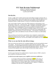
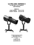
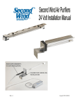
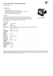
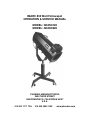
IMARC 850 Watt Followspot
OPERATION & SERVICE MANUAL
MODEL: IM-850/120
MODEL: IM-850/220
PHOEBUS MANUFACTURING
2800 THIRD STREET
SAN FRANCISCO, CALIFORNIA 94107
U.S.A.
415 550 1177 TEL
415 550 2655 FAX
www.phoebus.com
IMARC 850 Watt Followspot
OPERATION & SERVICE MANUAL
110-120 VAC & 220-240 VAC Models
January 2006
The intended use of this manual is for users and qualified service technicians.
CONTENTS
PAGE
LIMITED WARRANTY............................................................................................ 2
CONTROL DESCRIPTION
I. FOLLOWSPOT .................................................................................................. 3
II. BALLAST.............................................................................................................4
INITIAL SET UP...................................................................................................... 5
LAMP INSTALLATION.............................................................................................6
COLLAPSIBLE BASE ASSEMBLY ........................................................................ 7
FOLLOWSPOT OPERATION................................................................................. 8
FOCUSING............................................................................................................. 8
BEAM CONTROL................................................................................................... 8
FLAT FIELD ADJUSTMENT....................................................................................9
COLOR MEDIA INSTALLATION.............................................................................10
MAINTENANCE
I. LENS CLEANING................................................................................................11
II. LUBRICATION....................................................................................................11
III. TROUBLESHOOTING.......................................................................................11
TECHNICAL DATA
I. LAMP.................................................................................................................. 12
II. ELECTRICAL......................................................................................................12
USER NOTES........................................................................................................13
WARRANTY CARD ............................................................................................... 14
IMARC 850 WATT FOLLOWSPOT
IM-850/120, IM-850/220 USER MANUAL
LIMITED WARRANTY
Thank you for purchasing the Phoebus Manufacturing imarc 850.
The Phoebus Manufacturing imarc 850 watt followspot is warranted against defects in
material and workmanship for a period of one year from date of purchase from Phoebus
Manufacturing. In case of difficulty, contact Phoebus Manufacturing or your dealer for
repair or return instructions. Iris, dowser, and clipper are warranteed for six months under
normal use. Lamp and Ballast are warranteed by the Lamp Manufacturer (Ushio). Lamps
and ballast will be repaired or replaced at their discretion.
This warranty does not apply to mechanical defects caused by rough handling or to damage caused by improper operation not in accordance with this manual. Cause of defect
is in the sole judgement of Phoebus Manufacturing .
This warranty is voidable at Phoebus Manufacturing’s option under the following
Circumstances:
User makes unauthorized modifications (electrical or mechanical).
The unit is connected to improper voltage supply.
Any other condition occurs which causes catastrophic failure or impairs Phoebus
Manufacturing’s ability to render proper service.
If the unit is modified by the customer without permission, the customer agrees to pay for
any time or parts necessary to remove the modifications before repair, if necessary.
Phoebus will not be responsible for consequential damages caused by failure for whatever
reason of equipment of its manufacture. Sole liability is for equipment of its manufacture.
Sole liability is for repair or replacement (at Phoebus Manufacturing’s option) of the defective equipment under the terms described above.
2
IMARC 850 WATT FOllOWSPOT
IM-850/120, IM850/220 USER MANUAL
CONTROL DESCRIPTION
I. FOLLOWSPOT
1) 3 POSITION POWER SWITCH..................Controls power to fans and ballast
Down - Off
Middle - Fans only
Up - Ballast Auto strike, lamp run.
2) FUSE HOLDER...........................................Fuse 15 Amp 3AB
3) HOUR COUNTER.......................................Records operating time accumulated
on lamp. Operates in switch up position
Non-resetable.
4) REAR LENS CONTROL HANDLE..............Used to focus image. Turn handle clock
wise to lock and counter-clockwise to
unlock. Slide handle to focus beam.
5) FRONT LENS CONTROL HANDLE...........Changes image size. Turn handle clock
wise to lock and counter-clockwise to
unlock. Slide handle forward for smaller
image, spot distribution, long throws.
Slide back for larger image, flood distribution, or short throws..
6) DOWSER....................................................Mechanical dimmer. Gradually dims
to black out when lever is moved away
from the operator.
7) CLIPPER.....................................................Mechanical Blades mask spot to a
Rectangular strip. Open when lever is
moved towards operator.
8) IRIS.............................................................Controls size of image. Opens widest
when lever is moved towards operator
Iris does not fully close.
WARNING: Iris left in closed position
with dowser open for extended time
may cause damage to iris leaves.
9) COLOR CONTROL.....................................Color is inserted into beam when lever is
moved up and locks into place. The self
cancel feature will automatically release
the previously inserted frame when next
frame is locked into place. The release
lever is located on the top of the boom
housing. Pull up to release all six control
frames.
10) ADJUSTABLE YOKE TILT HANDLE.........Friction lock for vertical tilt of unit.
Push button for handle adjustment.
11) LINE CORD...............................................Plugs into 110-120 VAC wall outlet.
3
IMARC 850 WATT FOllOWSPOT
IM-850/120, IM850/220 USER MANUAL
12) REAR ACCESS DOOR.............................Allows operator access to lamp adjustscrews for hotspot adjustments.
13) THUMBSCREWS......................................Autoboom, front and rear housing
lockdown.
II. BALLAST EBM-801DC
1) WATTAGE ADJUSTMENT...........................The EMB-801-DC features a varible
wattage adjustment dial located inside
the ballast. The IM850 is an 850 watt
followspot and is factory set to 850
watts. Tampering with wattage setting
will compromise the lamp output and
lamp life.
220 VAC models are set at the factory
and there is no need for adjustments.
Ballast contains no user servicable
parts
4
MARC 850 WATT FOllOWSPOT
IM-850/120, IM850/220 USER MANUAL
INITIAL SET-UP
1)
2)
3)
4)
5)
6)
7)
8)
9)
10)
11)
12)
13)
14)
15)
16)
17)
18)
19)
20)
Unpack carefully and inspect for shipping damage.
Bolt the 4 base legs onto the 3 1/2” square tubing with the elevator
brackets and caster holes facing down. (See Collapsible Base
Assembly Instruction Diagram on page 6).
Insert casters into legs.
Insert levels into elevator brackets located at the end of each leg.
Insert height collar handle into height collar.
Slip height collar and handle onto yoke
Insert Teflon height collar washer onto yoke.
Insert yoke into base.
Turn tilt lock knobs on either side of the bail so 3/4” of thread is
showing. Position fiber washers nearest the bail.
Lift the imarc 850 using the front and rear of the chassis as
supports. Position the bail handle shafts in the U-shaped slots at
the top of the yoke. Ensure that the washers are positioned
properly. Turn the tilt lock knobs to tighten the grip on the yoke.
Remove shipping bolts and insert tapered handles into front and
rear lens holder.
Unscrew the four thumbscrews on either side of the color
boomerang.
Unpack boomerang. Position it upside down with the control levers
facing you.
Raise the left-hand (operator right) gel holder.
Insert gel, cover with ring and secure with three clips. Use hammer
or pliers to flatten the clips. (This will keep the gel frames from
catching on one another during use.)
Lower left-hand (operator right) gel holder and raise the next one.
Repeat steps #14 through #16. To access the bottom gel clip, raise
all the gels to the left or right and lower the one being worked on.
As you move toward the right-hand gels (operator left), insert
progressively lighter colors. The left hand (operator right) holder
should be used for deep blue or purple colors). This will prolong the life of the
gels.
Place the color boomerang on the top of the imarc 850 with the lever
handles facing the other operation controls. Secure with four thumbscrews near
the bottom of the boomerang.
Insert the three control handles (steel shaft with ball knob) into the
slots at the top and to the rear of front housing. The handles screw
into threaded holes which can be seen through the slots. A nyloc nut is provided
to secure control handle underneath the swivel. Note: To access the control
swivels, you must unscrew the ball knobs and carefully remove the main
housing (four thumb screws on either side secure housing to chassis.)
5
MARC 850 WATT FOllOWSPOT
IM-850/120, IM850/220 USER MANUAL
6
LAMP INSTALLATION
1) If main housing has not been removed in step 20, remove it now.
2) Make sure power switch is in off position & unplug unit from power source.
3) Carefully remove lamp from container taking care not to touch glass envelope.
ANODE WIRE
CATHODE
ANODE
SMH-850/D2 LAMP
4) Insert the lamp, Cathode first, through hole in reflector.
5) Carefully screw lamp into the Cathode Base, gripping it on the knurled part of the
Cathode end. Do not touch the glass envelope of lamp.
6) Attach the Anode wire to Anode Terminal Block. Tighten in place.
7) To remove lamp, reverse steps 5 & 6. It is not necessary to detach Anode wire
from Anode end.
8) Replace Main Housing, making sure that control handle shafts line up with their
respective slots. Secure Housing with thumbscrews, and screw ball knobs back
onto steel control shafts.
9) Plug the imarc into a 110-120v outlet, and turn switch to "on" position.
Overhead view of Lamp and Reflector with Main Housing removed.
MARC 850 WATT FOllOWSPOT
IM-850/120, IM850/220 USER MANUAL
7
COLLAPSIBLE BASE ASSEMBLY
Base is shipped unassembled. Parts
include Main Base Tube, 4 Base legs,
4 Casters, 4 Leveling Feet, 4 detent
pins, & 4 bolts, nylon washers, and
nylok nuts.
4) Rotate leg down and insert detent
pin into hole as shown.
5) Repeat steps 3 and 4 for remaining
base legs.
1) Screw casters into base legs
2) Screw leveling jacks onto base
leg extension feet. Secure with
3/8-16 hex nuts.
6. For storing or transporting base:
Remove detent pin and rotate leg
around lock nut. Replace pin to
lock legs securely in place.
3) Insert bolt through hole on the base leg as shown. Place nylon washer
on the bolt. Pass bolt through hole in main base tube and secure with nyloc
nut. NOTE: Nylon washer should be between base leg and main base
tube. Nyloc nut should be secured on inside of the base leg.
MARC 850 WATT FOllOWSPOT
IM-850/120, IM850/220 USER MANUAL
FOLLOWSPOT OPERATION
1) Connect to 120 Volt 60Hz power source. Turn power switch to middle posi
tion (lamp blower & gel fan only). Be sure both are operating properly before
flipping switch to upper position to strike lamp. The lamp should strike within
one second and warm up to full output within 60 seconds. The imarc 850 uses
a hot re-strike lamp. It is not necessary to run cooling fans after lamp is
turned off.
3) Dowser, Iris and Clipper are controlled by the ball knobs on top of imarc.
4) The Front Lens Control Handle (on lower side) is used to adjust lens for desired
throw by sliding it forward for a narrow beam (long throw) or towards the rear for
a wider beam (short throw). Handle may be locked in place by turning it clock
wise. Do not over tighten!
5) The Rear Lens Control Handle (side of unit, near middle) is used to obtain the
desired focus; soft or hard edge. Slide it forward for wide beam (short throw) or
backward for a narrowbeam (long throw). Handle may be locked in position by
turning clockwise. Do not over tighten!
6) To obtain the desired beam size and focus at a given distance, both lenses must
be moved. Lens position may be chalk marked on the side of the unit.
FOCUSING
1) Move iris, dowser, and clipper controls to extreme right hand position (viewing
the unit from the rear).
2) Move rear lens until edge of pattern is in focus. Position may be adjusted hard
or soft edge.
3) Close down the iris by moving its control handle left.
4) Focus may change slightly with iris closed. Best focus setting is with iris half
open.
5) To “zoom” the lenses to a new position, a coordinated motion of both front and
rear lenses is used. Note that these lenses move opposite to each other to
maintain focus.
BEAM CONTROL
1) The Dowser is a mechanical dimmer. The rear control handle is moved left to
close and right to open the dowser.
2) The Clipper shapes the image to a strip or rectangle of variable height. Move the
middle control handle left to close and right to open the clipper.
3) The Iris provides a 6 to 1 change in image diameter. It is controlled by the front
handle; left to close and right to open. The brightest spot is obtained with the iris
open and the lenses adjusted for the largest spot desired. Smaller spots are
obtained using the iris.
8
MARC 850 WATT FOllOWSPOT
IM-850/120, IM850/220 USER MANUAL
9
FLAT FIELD ADJUSTMENT
From time to time it may be necessary to optimize the position of the lamp in the reflector to attain desired flatness of field across the beam. In the imarc 850, this adjustment
may be made without removing the Main Housing.
1) Turn unit on and focus the beam on a light colored surface.
FOCUS KNOBS (3)
REAR ACCESS DOOR
2) Open the Rear Access Door found at back of unit.
3) Using the three focus knobs found on the Main Lamp Bracket, carefully
re-position the Lamp Adjustment Bracket to attain desired flatness of field.
Note: Adjustments should be done in small increments. Distance between
Main Lamp Bracket and the Lamp Adjustment Bracket is factory set at 7/8".
MAIN LAMP BRACKET
LAMP ADJUS. BRACKET
4) Close Rear Access Door and secure in place.
MARC 850 WATT FOllOWSPOT
IM-850/120, IM850/220 USER MANUAL
10
GEL INSTALLATION
1) Unscrew four thumbscrews on either side of the color boomerang.
2) Lift boomerang off. Position it upside down. Control levers should be facing you.
3) Raise the lever of the gel holder farthest to the left with the control levers facing
you on the boomerang and lower all the others.
4) Insert gel, cover with ring and secure with three clips. Use hammer or pliers to
flatten the clips. This will also keep the gel frames from hooking up on one another during use.
5) Lower first gel holder and raise the next one.
6) Repeat steps #3 through #5 for the remaining gel holders. To access the bottom
gel clip, raise all the gels to the left or right and lower the one being worked on.
7) As your move toward the right, insert progressively lighter colors. The farthest
left gel holder should be used for deep blue or purple gels. This will prolong the
life of the gel.
8) Replace boomerang assembly and secure with four thumbscrews. Due to the
extreme concentration of energy in the light beam and the unavoidable compromise between cooling power and fan noise, please load color boomerang so that
darkest gels are the farthest away from the light source.
NOTE: The use of HT or High Temperature color media is recommended for
use in the imarc 850.
DARKER COLORS
LIGHTER COLORS
imarc 850 boomerang assembly
MARC 850 WATT FOllOWSPOT
IM-850/120, IM850/220 USER MANUAL
MAINTENANCE
I. LENS CLEANING
1) Unscrew and remove Control Handle Knobs.
2) Remove Main Housing to access all lenses for cleaning.
3) Clean all lenses using glass cleaner and a soft, lint-free cloth.
4) Replace Main Housing.
5) Replace Control Handle Knobs.
6) Replace and tighten all thumbscrews.
II. LUBRICATION
1) Unscrew and remove Control Handle Knobs.
2) Remove Main Housing to access all lenses for cleaning.
3) Wipe all four bearing shafts with a clean cloth dampened with light wax or light
lubrication (WD-40). Avoid excess wax.
4) Operate front and rear lenses forward and back to distribute wax.
5) Replace Main Housing.
6) Replace Control Handle Knobs.
7) Replace and tighten all thumbscrews.
III. TROUBLESHOOTING – LAMP AND BALLAST (ELECTRICAL)
1) If blower fails to run, check power and fuse. Replace fuse with 10 amp 3AB
fuses.
2) If blower runs and lamp does not strike.
A. Check that the lamp is firmly seated in Cathode Base. Check that Anode
wire is firmly attached to Anode Terminal Block. If all appears normal, the
lamp may have reached the end of its life. Replace the lamp.
B. If the new lamp does not strike, check line voltages. Lamps may not start
with power line below 105 volts.
C. If the above measures are unsuccessful, the ballast is probably defective.
Call your distributor or Phoebus Manufacturing for further assistance.
11
MARC 850 WATT FOllOWSPOT
IM-850/120, IM850/220 USER MANUAL
TECHNICAL DATA
I. LAMP
The imarc 850 uses an Ushio SMH-850/D2 high intensity DC arc lamp. This is a 850
watt enhanced metal halide projection lamp. An electronic ballast is used to operate
the lamp from standard 120V, 50/60Hz power. Replacement lamps are available from
Ushio lamp distributors as well as from Phoebus Manufacturing.
Lamp life is an average of 1000 hours in normal use. The life depends on the burning time per start. Lamps burned for several hours per start will last longer. Operation
for less than 15 minutes per start is not recommended. An hour meter is mounted on
the housing to keep track of lamp life (or rental usage). Lumen loss occurs typically at
end of lamp life and the lamp will fail to start. Another end of life symptom is arc swirl
or flicker in the projected image. Occasionally, a new lamp may exhibit this problem.
Return such to your Ushio distributor for exchange.
Color temperature is about 5600° Kelvin (white) but may vary somewhat from lamp to
lamp.
In handling the lamp, avoid touching the arc tube. Always hold the lamp by the knurled
metal base of the Cathode. If the arc tube is touched, clean it with alcohol or freon before use to prolong lamp life. There is no explosion hazard in handling this lamp since
high pressure is present only when the bulb is hot.
The lamp is cooled by a blower located below the lamp. This blower is essential to
lamp operation. Improper cooling will cause decreased life and arc instability or color
shift.
II. ELECTRICAL
The imarc 850 operates on 105 to 125 Volt 50/60 Hz AC. Present models draw less than 15
amps, starting or running, at high power factor. An electronic ballast is used to supply the lamp
with proper starting and running voltages and currents.
12
MARC 850 WATT FOllOWSPOT
IM-850/120, IM850/220 USER MANUAL
NOTES
13
MARC 850 WATT FOllOWSPOT
IM-850/120, IM850/220 USER MANUAL
14
WARRANTY CARD
MODEL NUMBER
SERIAL NUMBER
DATE OF PURCHASE
PLACE OF PURCHASE (DEALER NAME)
USER’S NAME
COMPANY NAME
STREET ADDRESS
CITY
TELEPHONE
STATE
FAX
ZIP
EMAIL
Please fold along the dotted lines and staple
with return address on the outside as shown above.
Thank you!
Place
stamp
here
PHOEBUS MANUFACTURING
2800 THIRD STREET
SAN FRANCISCO, CA 94107
ATTENTION: WARRANTY DEPARTMENT