1
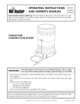
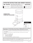
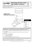
POST MIX SODA REFRIGERATION UNITS Models 2803/11/38/44 INSTALLATION GUIDE Manitowoc Beverage Equipment 2100 Future Drive Sellersburg, IN 47172-1868 Tel: 812.246.7000, 800.367.4233 Fax: 812.246.9922 www.manitowocbeverage.com In accordance with our policy of continuous product development and improvement, this information is subject to change at any time without notice. 07-18-07 REV0 FOREWORD Manitowoc Beverage Equipment (MBE) developed this manual as a reference guide for the owner/ operator, service agent, and installer of this equipment. Please read this manual before installation or operation of the machine. A qualified service technician should perform installation and startup of this equipment, consult the Troubleshooting Guide within this manual for service assistance. If you cannot correct the service problem, call your MBE Service Agent or Distributor. Always have your model and serial number available when you call. Your Service Agent ___________________________________________________________________ Service Agent Telephone Number ______________________________________________________ Your Local MBE Distributor ___________________________________________________________ Distributor Telephone Number _________________________________________________________ Model Number ______________________________________________________________________ Serial Number _______________________________________________________________________ Installation Date _____________________________________________________________________ UNPACKING AND INSPECTION Note: The unit was thoroughly inspected before leaving the factory. Any damage or irregularities should be noted at the time of delivery. WARRANTY INFORMATION Consult your local MBE Distributor for terms and conditions of your warranty. Your warranty specifically excludes all beverage valve brixing, general adjustments, cleaning, accessories and related servicing. Your warranty card must be returned to Manitowoc Beverage Equipment to activate the warranty on this equipment. If a warranty card is not returned, the warranty period can begin when the equipment leaves the MBE factory. No equipment may be returned to Manitowoc Beverage Equipment without a written Return Materials Authorization (RMA). Equipment returned without an RMA will be refused at MBE’s dock and returned to the sender at the sender’s expense. Please contact your local MBE distributor for return procedures. TABLE OF CONTENTS FOREWORD ........................................................................................................ 2 UNPACKING AND INSPECTION ......................................................................... 2 WARRANTY INFORMATION ............................................................................... 2 SAFETY ............................................................................................................... 4 IMPORTANT SAFETY INSTRUCTIONS ........................................................................... 4 CARBON DIOXIDE WARNING ......................................................................................... 4 QUALIFIED SERVICE PERSONNEL ................................................................................ 4 SHIPPING, STORAGE, AND RELOCATION ..................................................................... 4 ADDITIONAL WARNINGS ................................................................................................ 4 GROUNDING INSTRUCTIONS ........................................................................................ 5 DOS AND DON'TS ........................................................................................................... 6 INSTALLATION .................................................................................................... 7 ATTENTION: MARINE INSTALLATIONS .......................................................................... 7 OUTDOOR APPLICATIONS ............................................................................................. 7 PLUMBING SPECIFICATIONS ......................................................................................... 7 LOCATION REQUIREMENTS .......................................................................................... 7 REQUIREMENTS FOR POST MIX REFRIGERATION UNITS .......................................... 7 INTRODUCTION ............................................................................................................... 7 PREPARATION ................................................................................................................ 7 INSTALLATION OF THE REFRIGERATION UNIT ............................................................ 8 POSITIONING THE REFRIGERATION UNIT .................................................................... 8 PLUMBING REQUIREMENTS .......................................................................................... 8 ELECTRICAL PROVISIONS ............................................................................................. 9 CONNECTING TOWERS AND CONDUIT ........................................................................ 9 INSULATING CONNECTIONS .......................................................................................... 9 SEALING INSTRUCTIONS ............................................................................................... 9 CONNECTING SUPPLY LINES ...................................................................................... 10 PROCEED WITH THE FOLLOWING TESTS ................................................................... 11 TESTING THE CARBONATED WATER CIRCUITRY ...................................................... 12 SANITIZING PRIOR TO STARTUP ................................................................................. 12 REMOTE CONDENSER REQUIREMENTS .................................................................... 12 CONNECTING THE PRE-CHARGED REFRIGERATION LINES .................................... 14 HOW TO SHORTEN THE LINE SET ............................................................................... 14 HOW TO RE-CHARGE THE LINE SETS ........................................................................ 14 AEROQUIP CONNECTION ............................................................................................ 16 OPERATION ...................................................................................................... 16 PLACING EQUIPMENT IN OPERATION ........................................................................ 16 ELECTRICAL SPECIFICATIONS ................................................................................... 16 SERIAL PLATE LOCATION ............................................................................................ 17 USER MAINTENANCE ...................................................................................... 18 SANITIZING SYRUP CIRCUITS AND TESTING SYRUP CIRCUITRY ............................ 18 50M 50HZ MODELS ....................................................................................................... 19 50M 60HZ MODELS ....................................................................................................... 20 INDEX................................................................................................................. 23 SAFETY IMPORTANT SAFETY INSTRUCTIONS Carefully read all safety messages in this manual. Learn how to operate this unit properly. Do not allow anyone to operate the unit without proper training and keep it in proper working condition. Unauthorized modifications to the this unit may impair function and/or safety and affect the life of the unit. CARBON DIOXIDE WARNING DANGER: Carbon Dioxide (CO2) displaces oxygen. Exposure to a high concentration of CO2 gas causes tremors, which are followed rapidly by loss of consciousness and suffocation. If a CO2 gas leak is suspected, particularly in a small area, immediately ventilate the area before repairing the leak. CO2 lines and pumps should not be installed in an enclosed space. An enclosed space can be a cooler or small room or closet. This may include convenience stores with glass door self serve coolers. If you suspect CO2 may build up in an area, venting of the B-I-B pumps and / or CO2 monitors should be utilized. QUALIFIED SERVICE PERSONNEL WARNING: Only trained and certified electrical and plumbing technicians should service this unit. All wiring and plumbing must conform to national and local codes. SHIPPING, STORAGE, AND RELOCATION CAUTION: Before shipping, storing, or relocating this unit, syrup systems must be sanitized. After sanitizing, all liquids (sanitizing solution and water) must be purged from the unit. A freezing environment causes residual sanitizing solution or water remaining inside the unit to freeze, resulting in damage to internal components. ADDITIONAL WARNINGS Installation and start-up of this equipment should be done by a qualified service technician. Operation, maintenance, and cleaning information in this manual are provided for the user/operator of the equipment. Save these instructions. Installation and Service Manual SAFETY GROUNDING INSTRUCTIONS WARNING: Risk of electrical shock. Connect to a properly grounded outlet only. This appliance must be grounded. In the event of malfunction or breakdown, grounding provides a path of least resistance for electric current to reduce the risk of electric shock. This appliance is equipped with a cord having an equipment-grounding conductor and a grounding plug. The plug must be plugged into an appropriate outlet that is properly installed and grounded in accordance with all local codes and ordinances. DANGER – Improper connection of the equipment-grounding conductor can result in a risk of electric shock. The conductor with insulation having an outer surface that is green with or without yellow stripes is the equipment grounding conductor. If repair or replacement of the cord or plug is necessary, do not connect the equipment-grounding conductor to a live terminal. Check with a qualified electrician or serviceman if the grounding instructions are not completely understood, or if in doubt as to whether the appliance is properly grounded. Do not modify the plug provided with the appliance – if it will not fit the outlet, have a proper outlet installed by a qualified electrician. WARNING – When using electric appliances, basic precautions should always be followed, including the following: a) Read all the instructions before using the appliance. b) To reduce he risk of injury, close supervision is necessary when an appliance is used near children. c) Do not contact moving parts. d) Only use attachments recommended or sold by the manufacturer. e) Do not use outdoors. f) For a cord-connected appliance, the following shall be included: • Do not unplug by pulling on cord. To unplug, grasp the plug, not the cord. • Unplug from outlet when not in use and before servicing or cleaning. • Do not operate any appliance with a damaged cord or plug, or after the appliance malfunctions or is dropped or damaged in any manner. Return appliance to the nearest authorized service facility for examination, repair, or electrical or mechanical adjustment. g) For a permanently connected appliance – Turn the power switch to the off position when the appliance is not in use and before servicing or cleaning. h) For an appliance with a replaceable lamp – always unplug before replacing the lamp. Replace the bulb with the same type. i) For a grounded appliance – Connect to a properly grounded outlet only. See Grounding Instructions. SAVE THESE INSTRUCTIONS 5 Installation and Service Manual SAFETY DOS AND DON'TS Caution: To Avoid Serious Injury Important: Read the following warnings before beginning an installation. Failure to do so may result in possible death or serious injury. DO Adhere to all National and Local Plumbing and Electrical Safety Codes. DO Turn “off” incoming electrical service switches when servicing, installing, or repairing equipment. DO Check that all flare fittings are tight. This check should be performed with a wrench to ensure a quality seal. DO Inspect pressure on Regulators before starting up equipment. DO Protect eyes when working around refrigerants. DO Use caution when handling metal surface edges of all equipment. DO Handle CO2 cylinders and gauges with care. Secure cylinders properly against abrasion. DO Store CO2 cylinder(s) in well ventilated areas. DO NOT Exhaust CO2 gas (example: syrup pump) into an enclosed area, including all types of walk in coolers, cellars, and closets. DO NOT Throw or drop a CO2 cylinder. Secure the cylinder(s) in an upright position with a chain. DO NOT Connect the CO2 cylinder(s) directly to the product container. Doing so will result in an explosion causing possible death or injury. It is best to connect the CO2 cylinder(s) to a regulator(s). DO NOT Store CO2 cylinders in temperature above 125°F (51.7°C) near furnaces, radiator or sources of heat. DO NOT Release CO2 gas from old cylinder. DO NOT Touch Refrigeration lines inside units; some may exceed temperatures of 200°F (93.3°C). NOTICE: All utility connections and fixtures shall be sized, installed, and maintained in accordance with Federal, State, and Local codes. 6 Installation and Service Manual INSTALLATION ATTENTION: MARINE INSTALLATIONS WARNING! This unit is for use on vessels over 66 ft (20 m) in length. This unit should not be installed in the engine space of a gasoline-powered ship. NOTE: This unit must be secured to the vessel during installation, TS models are NOT marine listed. OUTDOOR APPLICATIONS TS Multiplex Beverage Recirculating units are approved and listed by Underwriters Laboratories (UL). However they are not UL approved for weather exposure applications. These units must be installed in areas where adequate protection from the elements is provided, all other models are ETL listed. PLUMBING SPECIFICATIONS A 1" (2.54 cm) ID copper inlet water line equipped with a 3/4" (1.905 cm) FPT sweat adapter with shut-off must be supplied by plumber at rear of equipment. Appropriate floor drains should be provided within 6 ft (183 cm) of each unit installed. Note: The carbonator in this unit is provided with a dual check valve type back-flow preventer, which conforms to ASSE 1032. Potable water connections to the equipment must comply with the basic plumbing code of the Building Officials and Code Administrators International, Inc. (BOCA) and the Food Service Sanitation Manual of the Food and Drug Administration. Verify local plumbing code requirements. LOCATION REQUIREMENTS Select a location for the refrigeration unit that meets the requirements of the building plans, local codes, and personnel. The unit must be positioned for free airflow as well as for future service. The following requirements must be met: • • 100 GPH (379 LTR/hr) potable water supply Models 2803/11/38 Beverage quality CO2 gas (bulk or bottled supply) with a minimum 3/8" (0.96 cm) line • • 200 GPH (757 LTR/hr) potable water supply Models 44/50 One (1) Bag-In-Box (BIB) container of each postmix syrup flavor. NOTE: Refer to nameplate on side of refrigeration unit for voltage and amperage specifications. Make all electrical connections at the junction box located at the top rear of unit. Optional equipment may require additional power supplies. NOTE: Potable water connections to the equipment must comply with local plumbing code requirements, particularly the back-flow prevention requirements. REQUIREMENTS FOR POST MIX REFRIGERATION UNITS • Conduit can be run through floor or ceiling chase. • Syrup supply can be located on stand or adjacent to refrigeration unit. IMPORTANT: The remainder of these instructions is to be completed by an authorized Multiplex Installer. INTRODUCTION These equipment instructions are intended to assist qualified personnel in the unpacking, locating and the initial operation of the Multiplex Beverage Equipment Post Mix Refrigeration Unit. IMPORTANT: This publication should be saved for future reference. Read instructions before attempting installation. PREPARATION The Multiplex Beverage Equipment Post Mix Refrigeration Unit is pre-assembled in the factory and requires minimum installation. For future reference or to be used when ordering parts, record the Model Number, Serial Number, Part Numbers of Unit, Condenser (if remote), Towers, etc., and Date of Installation on the inside of this Manual. Leave manual on site in a safe place. Do not discard manual. 7 Installation and Service Manual INSTALLATION INSTALLATION OF THE REFRIGERATION UNIT Before proceeding with installation, verify that all requirements for roof mounted remote condenser units (if applicable) have been satisfied. If unit has a remote condenser, refer to the instructions on installing the remote condenser supplied with the Condensing unit and refer to section on installation of remote refrigeration line sets. POSITIONING THE REFRIGERATION UNIT Identify the appropriate location where the refrigeration unit and any optional equipment will be placed. Locate and assemble all optional equipment that is to be installed on the refrigeration unit. Inspect for shortages and complete kit assemblies. 1. Install all brackets and support legs (if not using optional stand) before placing equipment in the proper location. 2. Select a location for the unit that meets the requirements of the building plans, local codes, and personnel. The unit should be placed in a location that will allow ease of maintenance and no obstruction of airflow. 3. A floor drain must be available within six (6) feet (183 cm) of the unit and access to incoming water supply and electrical outlets is a pre-installation requirement. 4. The backside of the unit should be at least six (6) inches (15.2 cm) away from the wall (refer to figure 1). 5. Remove the top cover of the unit and expose the water bath and conduit connections. TOP VIEW SIDE VIEW PLUMBING REQUIREMENTS Incoming water supply should be provided before installation of the refrigeration unit and should comply with local plumbing requirements. 1. A minimum 1" (2.54 cm) water supply line with a 3. Connect the Water Manifold Supply Line, located on manual shut-off valve must be plumbed at least 6ft the bulkhead panel in the motor compartment to the (183 cm) from the unit. The incoming water supply main water supply. The Main Water Supply Shut-off pressure must not exceed 70 PSI static (4.8 bar) and Valve must remain in the “OFF” position. If a water filter be no less than 40 PSI (2.8 bar) dynamic. is to be installed, connect the line to the outlet fitting of the filter. Plumb according to applicable plumbing codes. 2. Locate the drain hose, bracket, and two (2) screws provided in the Installation Kit. Attach the drain hose 4. When a Water Cooled Condenser is installed, a copto the water bath overflow tube located on the bottom per supply line (not supplied with unit) must be of the Refrigeration Unit. plumbed to the 3/8" (.965 cm) Male Flare fitting installed in the Water Shut-off Assembly. The Shut-off must be placed in the “OFF” position. A copper drain line (not supplied) is to be connected to the outlet fitting of the Water Cooled Condenser and routed to the floor drain. DRAIN HOSE CONNECTION 8 Installation and Service Manual INSTALLATION ELECTRICAL PROVISIONS Electrical service must agree with the requirements noted on the unit serial number plate. An opening is provided in the side of the unit to route service to the field-wiring box. Wiring must conform to applicable codes. 1. For domestic units, one or more 15 Amp, 120 Volt 2. For international versions, refer to codes directly on wall receptacle will be required if accessories such the optional equipment installed and to the wiring as a CO2 Control Assembly, Air Pump, or Water diagram. Booster Pump are installed with the unit. CONNECTING TOWERS AND CONDUIT Refer to the installation instructions packaged with the towers or other dispensing equipment and with the conduit used. INSULATING CONNECTIONS 1. Make sure all exposed carbonated water and syrup lines are well insulated on towers to conduit, conduit junctions, refrigeration unit to conduits, and Drive-Thru junction. 2. To insulate the above use the leftover conduit sections and tape. 3. Cut the conduit sections to fit like a glove over the exposed lines and fittings. A little extra time spent doing a professional job initially will eliminate a call back in several days to make corrections. SEALING INSTRUCTIONS Refer to the installation instructions packaged with the conduit used. (Aerosol foam not supplied with unit or conduit) SEALING THE FLOOR CHASE 9 Installation and Service Manual INSTALLATION CONNECTING SUPPLY LINES Pre-installation of towers is required and the appropriate syrup supply must be connected to the corresponding tower. The valves are numbered 1-6, 1-8, or 1-10 from left to right viewing from the front of the tower. 1. For a two (2) tower installation, refer to the Syrup Supply Line Diagram below. The syrup product supply boxes can be positioned on a BIB rack in a convenient location near the soda system. Note: Refer to the optional equipment component installation instructions for completion (if applicable) of the beverage system. Do not connect the syrup supply at this time. 2. Locate the conduit supply lines for the refrigeration unit. There are four (4) ½” (1.27 cm) carbonated water lines marked in sets for the system. Connect the yellow carbonated water supply line (7) to the yellow carbonated water return line (A). Connect the blue carbonated water supply line (8) to the blue carbonated water return line (B). Refer to the Carbonated Water Supply Line Diagram below. 10 Installation and Service Manual INSTALLATION CONNECTING SUPPLY LINES 3. Locate the one (1) and the (8) 3/8" (.965 cm) syrup lines. Note: Braided syrup lines located inside the conduit bundle are used to prevent flavor transfer. Braided syrup lines located outside the conduit bundle are used for unsweetened tea or syrup that are like to precipitate (if applicable). 4. Insert the eight (8) John Guest adaptors into the elbows on the syrup coils. Note: The 3/8" (.965 cm) and ½ “(1.27 cm) adapters are supplied for either size conduit. 5. Locate the plain water line(s) in the conduit. Determine the size, either 3/8" (.965 cm) or ½” (1.27 cm) and the number (one [1) or two [2]. Jumper the line labeled “W”. Either connect two (2) splicers for two (2) water lines or use one of the tees supplied to connect the two (2) lines together. 6. Insert the conduit supply lines into the left hand opening of the refrigeration unit. Connect the John Guest fittings requiring the longest tube from the end of the insulation first. Use two (2) tab clamps each per connection. It may be necessary to moisten the lines and fittings before inserting the tubing over the barbed fitting. Alter the remaining lines to make the routing neat and secure. 7. Connect the CO2 supply line from the CO2 tank regulator to the line marked CO2 in the unit using a 3/8" (.965 cm) by 3/8" (.965 cm) splicer and secure with Oetiker clamps. PROCEED WITH THE FOLLOWING TESTS • • • • • Assure that overflow tube is firmly seated, not leaking. Check Conduit for proper support and insulation. Cycle Carbonator “A” momentarily. Cycle Carbonator “B” momentarily (if applicable). Cycle Circulating Motor “A” momentarily. • • • • Cycle Circulating Motor “B” momentarily (if applicable). Cycle Compressor momentarily. Assure that Agitator Motor is running. Assure that Ice Bank Control Probe is securely attached to evaporator coil. 11 Installation and Service Manual INSTALLATION TESTING THE CARBONATED WATER CIRCUITRY 1. Turn “ON” the CO2 Tank Regulator corresponding to circuit “A”. Adjust the setting to 90 PSI (6.2 bar). 2. Open the pressure relief on the top of the carbonator tank for circuit “A”. Make sure the other valve is closed. 3. Allow the CO2 gas to enter the system. 4. Wait for 2 or 3 minutes before turning “OFF” the CO2 Tank Valve. This will allow the lines to expand under pressure. 5. Turn “OFF” CO2 Vessel Regulator Valve. Observe pressure on the high pressure gauge. The needle dropping will indicate a loss in pressure. If the needle continues to fall, a leak in the system must be corrected. Observe the pressure for several minutes. 6. The greater the leak, the faster the needle will drop. The smaller the leak, the slower the needle will drop. 7. Repeat procedure for circuit “B” if applicable. 8. Turn “ON” the water supply. Turn “ON” the water supply to both carbonators. Turn “ON” the rocker switches marked carbonator “A” (and “B” if applicable). Note: Carbonator motors should run approximately 2 minutes before shutting “OFF” on initial start-up. 9. After carbonators “A” (and “B” if applicable) cycle OFF”, turn “ON” the rocker switches marked circulator “A” (and “B” if applicable). NOTE: It may be necessary to use soap solution at all connections to locate a very small leak. SANITIZING PRIOR TO STARTUP Prior to putting system into service, clean and sanitize the system. During this process, check all syrup circuit connections from the BIB connector through the water bath area to the inlet fitting and stainless steel tubing of the tower. Check syrup circuitry on all towers by activating the valve of the circuit being tested. Repair any leaks prior to hooking up syrup. See SANITIZING SYRUP CIRCUITS AND TESTING SYRUP CIRCUITRY in the User Maintenance section. PRE-INSTALLATION REQUIREMENTS 1. 2. 3. 4. 1. 2. 12 Multiplex Remote Condenser Requirements this trap allows oil to reach the condenser and return to Installation and maintenance are to be performed only by the compressor. qualified refrigeration personnel. These technicians must have EPA certification (USA), are familiar with local codes 3. The easiest method to create a trap is to bend the tubing (smoothly, no kinks) into the trap form (refer to figure 3). and regulations, and are experienced with this type of 4. The trap(s) should be of minimum height of 3" (7.6 cm) remote refrigeration equipment. and a width of 6" (15.2 cm) to minimize oil accumulation. As a condition of the warranty, the check, test and start-up The traps can also be bent out of the refrigeration tubing. procedure must be performed by qualified personnel. Carefully bend the tubing down 12" and sweeping the Because of possible shipping damage, check both the tubing back up. condensing unit and refrigeration unit(s) for refrigerant 5. It is critical that the Multiplex remote condensing line size leaks. If the refrigeration unit is located on a roll out platform, you specifications for the specific model be maintained. The must coil up to one round between the back of the stand specifications are ½” discharge and 3/8" liquid lines. and the wall. This allows pull out of the refrigeration unit for servicing. If the refrigeration unit is located in a stationary location, you must remove excess refrigeration tubing as described below. Multiplex Pre-charged Refrigeration Lines Requirements Both the discharge and liquid remote condensing lines should be kept to a minimum distance for maximum performance. All Multiplex systems are capacity rated to 100 ft (30.5 m) tubing distance between the compressor and condenser. Any vertical rise 25 ft (7.62 m) or greater must have a manufactured or installed trap (bend), in the discharge refrigeration line from the compressor to the remote condenser. A trap is necessary for every additional 25 ft (7.62 m) vertical rise. When excessive vertical rise exists, Installation and Service Manual INSTALLATION INSTALLING THE MULTIPLEX REMOTE CONDENSER The Multiplex remote condensing units have a 208-230 Volt, 50/60 HZ, 1 PH fan motor that includes a permanent split capacitor and internal overload protection. The electrical wires from the refrigeration unit wire to the condenser. The electrical installation should be in accordance with local codes, national Electrical Code and regulations. 1. Determine a position for installation that will allow access for maintenance and is free from obstruction. Verify hot air discharge from other condensers do not interfere with the inlet of this condenser. 2. Install the four (4) legs to the sides of the condenser using the mounting bolts provided. 3. The General Contractor or Owner must secure two (2) treated lumber 4" x 4" x 36" (or longer). You may then mount the remote condenser to the treated lumber (refer to figure 1). 4. The General Contractor or Owner must install a 3" pitch pot in the roof (refer to figure 2). Then seal for weather protection. 5. Locate the pre-charged refrigeration lines shipped with the system. These lines should be a correct length for the building design. Avoiding any kinks, neatly route these lines from the remote condenser to the refrigeration unit. Excess refrigeration tubing must be handled in one of two ways. When coiling the excess tubing, make sure the inlet to the coil is at the top of the coil and the exit is the bottom of the coil. There can be no more than one turn to the coil. If you have more tubing, you must cut out the excess before connecting the ends. When cutting the tubing, you must first evacuate the refrigerant (line sets have a positive refrigerant holding charge of two to three ounces). After shortening and welding the tubing together again, you must vacuum the tubing to 250 microns. Then recharge the tubing with the appropriate refrigerant at 0.72 ounces per foot of new tubing length measured one way. Figure 5 Caution: Excess refrigeration tubing must be properly cared for before being connected to either the remote condenser or refrigeration unit. Figure 6 Caution: Excess refrigeration tubing must be properly cared for before being connected to either the remote condenser or refrigeration unit. 13 Installation and Service Manual INSTALLATION CONNECTING THE PRE-CHARGED REFRIGERATION LINES Note: Before connecting the pre-charged refrigeration lines, the refrigeration unit must be properly located, leveled, and the water bath filled 1" (2.5 cm) below the installed drain pipe. 1. Attach low side gauge set to service port on each line set to verify positive pressure within the line set. Note: If for any reason the lines are damaged and / or leaking or the lines no longer charged, refer to “How To Re-charge the Line Sets”. If the line set is too long for the application, refer to “How To Shorten the Line Sets”. 2. Always make the connections at the condenser first, using the end of the pre-charged lines with the valve ports. 4. Connect the refrigeration unit side with the quick connects (discharge and liquid). Make sure to provide discharge trap at back of refrigeration unit, or bend discharge line down 12" and then up smoothly (no kinks) to provide a trap. 5. If a low refrigerant charge is detected, recover and recharge the system adding the unit name plate charge, condenser name plate charge, and the refrigerant line charge at 0.72 ounces per foot (0.067 kg/m), measured one way. 3. Connect the condenser side with the quick connectors (discharge and liquid) up to condenser. Refer to the section titled “Aeroquip connection” in these instructions. HOW TO SHORTEN THE LINE SET 1. Do not connect either end of the tubing to the system before everything is set in place. Standard refrigeration practices must be followed regarding the tubing installation. 2. Excess refrigeration tubing must be handled in one of two ways. With a short amount of excess tubing (about 10 feet), you may coil that amount vertically between the condenser and refrigeration unit. When coiling the excess tubing, make sure the inlet to the coil is at the high side of the coil and the exit is the low side of the coil. There can be no more than one turn to the coil. The coil must continue in a downward spiral with no overlaps, similar to a cork screw. If you have more tubing, you must cut out the excess before connecting the ends. When cutting the tubing, you must first evacuate the refrigerant. 3. After shortening the tubing and welding together again, you must vacuum the tubing to 250 microns. 4. Recharge the tubing with the appropriate refrigerant at 0.72 ounces per foot (0.067 kg/m) of new tubing length, one way. HOW TO RE-CHARGE THE LINE SETS Note: This procedure to be used only with damaged or evacuated line sets or with unknown refrigerant type. 1. Repair any damages to the line sets before proceeding. 2. With the remote condenser lines properly hooked and sealed to the condenser, evacuate to 250 microns for 1 hour, using both Schrader ports on the service line set. 3. For units with model numbers beginning with SSxxxxxx, charge the condenser and line set as described here. Add 0.72 oz/ft (0.067 kg/m) of remote line set (one way run distance) plus condenser name plate charge. Example: 45 ft of line set 45 x 0.72 oz = 32.4 oz 32.4 oz + condenser charge = Total charge 14 4. If the line set and the main refrigeration unit are connected, you must also add that refrigerant charge. Recharging line sets and condensers connected to refrigeration model numbers TSxxxxxx. Charge according to the nameplate charge on the refrigeration unit. That is enough refrigerant for up to 100 feet of tubing plus the Multiplex condenser. If you have another brand condenser, please add additional charge for the condenser (example: up to three pounds for a MAC condenser). Connect line sets to the proper discharge and liquid mating connectors on the refrigeration unit using quick connects. Refer to the section titled “Aeroquip Connection” in these instructions. Installation and Service Manual INSTALLATION HOW TO RE-CHARGE THE LINE SETS (CONTINUED) 5. Be sure to observe proper refrigeration techniques when running the line set. a. The discharge line should loop down at the compressor end to trap liquid from returning to the compressor (refer to figure 3), unless you are coiling refrigeration tubing behind the unit. b. The discharge line should loop above discharge connector at the condenser to resist liquid returning to the compressor. Any excess tubing should be removed from the line set before the line set is connected to any equipment. c. The discharge line should have one P trap every 25 ft (7.6 m) of vertical rise to allow oil to stair-step up to the condenser and eventually return to the compressor. Note: When the connections are made, the seal in the couplings are broken and if removed for any reason, the refrigerant charge will be lost. Caution: Relays and terminal block are energized from each remote unit. Turn “off” switches on each unit before opening quick disconnect switch on condensing unit. On the completion of the wiring of the remote condenser make sure the electrician placed the switch lever in the “on” position. This switch must be “on” before turning “on” the refrigeration toggle switch on the unit. Also, the water bath must be filled with water. Figure 7 CAUTION: Relays and terminal block are energized from each remote unit. Turn “off” switches on each unit before opening quick disconnect switch on condensing unit. On the completion of the wiring of the remote condenser make sure the electrician placed the switch lever in the “on” position. This switch must be “on” before turning “on” the refrigeration toggle switch on the unit. Also, the water bath must be filled with water. 15 Installation and Service Manual INSTALLATION AEROQUIP CONNECTION 1. Lubricate male half diaphragm and synthetic rubber seal with refrigerant oil. 2. Thread male coupling to its proper female half by hand to insure proper mating of threads. 3. Use proper wrenches (on coupling body hex and its union nut) and tighten union nut until coupling bodies “bottom”. Note: You must use a wrench on the body to keep the body from turning while tightening the nut with the second wrench. If the body turns excessively, the piercing seal will be damaged. 4. Use proper wrenches to tighten an additional ¼ turn (90°). This final ¼ turn is necessary to insure the formation of a leak proof joint. Alternately, use a torque wrench to tighten ½” coupling to 40 ft lbs and 3/8" fitting to 11 ft lbs. 5. Leak check all your connections. If you detect any leaks, repair and recheck. 1. Fill the refrigeration unit water bath tank with water to OPERATION PLACING EQUIPMENT IN OPERATION Before placing equipment in operation, verify that all requirements for roof mounted Remote Condenser Units (if applicable) have been satisfied. Refer to the instructions on installing the Remote Condenser. 6. The refrigeration unit will build an ice bank in approxi1. Fill the refrigeration unit water bath tank with water to mately 4 to 6 hours. within 1/2" (1.27 cm) of the top of the overflow tube. 7. If optional CO2/Water Control Panel has been installed 2. Open the manual Water Shut-off Valve to the Water Cooled Condenser (if applicable). on the refrigeration unit, refer to the installation instruc3. Turn “ON” the rocker switch labeled “Refrigeration” to tions for operation and testing the circuits for leaks. begin building an ice bank. 8. The carbonation circuits “A” and “B,” as well as the 4. Turn “ON” the rocker switch labeled “Agitator”. syrup circuits must be checked for leaks and possible 5. Ice should begin to form on the evaporator coils in cross circuits before turning “ON” the water supply to approximately 2 hours. carbonator pumps. ELECTRICAL SPECIFICATIONS POST-MIX SODA REFIGERATION UNIT SPECIFICATIONS MODEL PART NUMBER VOLTAGE HZ PHASE WIRES BREAKER CONDENSER REMOTE 11MA04 SS901120 120VAC 60 1 3 30 AMP Air Cooled NA 11MAX04 SS901122 230 VAC 50 1 3 16 AMP Air Cooled NA 2803AX04 SS902832 230 VAC 50 1 3 16 AMP Air Cooled NA 2803A04 SS902850 120VAC 60 1 3 25 AMP Air Cooled NA 38MAO4 SS903850 120VAC 60 1 3 30 AMP Air Cooled NA 38MWO4 SS903852 120VAC 60 1 3 30 AMP Water Cooled NA 44MA04 SS904480 208/230 VAC 60 1 3 30 AMP Air Cooled NA 44MR04 SS904481 208/230 VAC 60 1 3 30 AMP Remote Air Cooled 00904814 44MW04 SS904482 208/230 VAC 60 1 3 30 AMP Water Cooled NA 44MAX04 SS904483 230 VAC 50 1 3 25 AMP Air Cooled NA 44MRX04 SS904484 230 VAC 50 1 3 25 AMP Remote Air Cooled 00904814 50MA04 TS905050-263 120/208-230 VAC 60 3 4 30 AMP Air Cooled NA 50MR04 TS905051-263 120/208-230 VAC 60 3 4 30 AMP Remote Air Cooled 00904814 50MW04 TS905052-263 120/208-230 VAC 60 3 4 30 AMP Water Cooled NA 50MR04 Q/T TS905046-263 120/208-230 VAC 60 3 4 30 AMP Remote Air Cooled 00904814 50MAX04 TS905053-353 230/400 VAC 50 3 5 16 AMP Air Cooled NA 50MRX04 TS905054-353 230/400 VAC 50 3 5 16 AMP Remote Air Cooled 00904814 50MWX04 TS905055-353 230/400 VAC 50 3 5 16 AMP Water Cooled NA NOTICE: See nameplate on refrigeration unit for electrical specifications. Make all electrical connections at the junction box located at the top of the rear wall of the refrigeration unit pump compartment in accordance with applicable electrical codes. Power disconnect must be installed within sight of unit. 16 Installation and Service Manual OPERATION SERIAL PLATE LOCATION 17 Installation and Service Manual USER MAINTENANCE SANITIZING SYRUP CIRCUITS AND TESTING SYRUP CIRCUITRY The following is needed to clean and sanitize the Bag-in-Box (BIB) beverage system: · · · Three (3) clean buckets Plastic brush or soft cloth Mild detergent 1. Prepare the following in buckets: · Bucket 1 – warm (100° F/38° C) tap water for rinsing 2. 3. 4. 5. 6. 7. 8. 9. 18 · Bucket 2 - mild detergent and warm (100° F/38° C) water · Bucket 3 – mix a solution of unscented bleach (5% NaClO) or commercial sanitizer and warm 100° F/38° C) water. Mixture should supply 100 PPM available chlorine —1/4 oz. (30ml) bleach to 1 gallon (3.8 liters) water. Disconnect the “syrup-line side” of the BIB connector. Rinse connector in warm (100° F/38° C) water. Connect syrup connector to BIB connector and immerse both into Bucket 1. A “bag side” connector can be created by cutting the connector from an empty disposable syrup bag. Draw rinse water through system until clean water is dispensed. Most beverage valves allow the syrup side to be manually activated by depressing the syrup pallet. Connect Bucket 2 to system. Draw detergent solution by activating valves until solution is dispensed. Repeat steps 2-7 until all syrup circuits contain detergent solution. Allow detergent solution to remain in system for five (5) minutes. · · Unscented bleach (5% NaClO) or commercial sanitizer Bag-in-Box (BIB) connector 10. Connect Bucket 3 to system. 11. Draw sanitizing solution through system by actuating valves until solution is dispensed 12. Repeat step 11 until all syrup circuits contain sanitizer solution. 13. Allow sanitizer to remain in system for fifteen (15) minutes. 14. Remove nozzles and diffusers from beverage valves. 15. Scrub nozzles, diffusers, and all removable valve parts (except electrical parts) with a plastic brush or a soft cloth and the detergent solution. 16. Soak nozzles, diffusers, and removable valve parts (except electrical parts) in sanitizer for fifteen (15) minutes. NOTE: DO NOT soak nozzles, diffusers, or other valve parts overnight. 17. Replace nozzles, diffusers, and valve parts. 18. Connect Bucket 1 to system. 19. Draw rinse water through system by activating valves until no presence of sanitizer is detected. 20. Attach syrup connectors to BIB’s. 21. Draw syrup through system by activating valves until only syrup is dispensed. 22. Discard first two (2) drinks. Installation and Service Manual EXPLODED VIEWS *Drawing Details on next page NO. 1 2 3 4 5 6 7 8 9 10 11 12 13 14 15 16 17 18 19 20 21 22 23 24 25 Part Number 000000979 000001430 000001973 000002232 00219105 2002483 2002523 2002543 2002733 2002743 2002753 2002763 2002893 2006613 3001723 3001873 3002043 3002073 3002083 3002173 4010243 4010253 5001023 5001183 5001343 Description TUBE RUBBER .75IDX.125WX72 FILTER AIR MANIFOLD WATER 3 OUTLET MANIFOLD WATER 3 OUTLET CTRL, LIQ LEVEL, 240- 1/3HP RELAY,THERM. TIME DELAY DPSTNC LAMP IND 250V RED W/3/16 TABS MOTOR, CARB - 230V, 1/3HP SENSOR, ELEC. ICE BANK CNTRL SWITCH,PRESS. 4PSI LOW WATER PUMP, 100 GPH - S/STEEL PUMP, 100 GPH-BRASS,FLTR,250 PSI SWITCH, ROCKER - SPST, 16A CONTACTOR - 3 POLE 208/240V PIPE, STAND - 24.25 LG TANK, CARB - ASSY TUBE, SS n.312 OD, COIL TUBE, SS - .375 OD, PLAIN WTR TUBE, SS - .375 OD, SYRUP TUBE, SS n.312 OD, COIL BOOT, MOTOR PUMP BOOT, MOTOR PUMP VALVE BALL 3/8 FPTX3/8 FPT BRAS ELBOW - .375 BARB X .375 MPT VALVE,SHTFF-1/4 TURN,JG,1/4FPTX3/8 TUBE NO. 26 27 28 29 30 31 32 33 34 35 36 37 38 39 40 41 42 43 44 45 46 47 48 49 50 Part Number 5001463 5001613 5001793 5001803 5001823 5001833 5001873 5001903 5001963 5001983 5002033 6052031 6052071 8251513 8332023 000000579 Y0208032 Y0208031 7601431 020001414 020001715 020001716 5009036 00213237 7601431 Description VALVE, TGLE RELF 150# 1/8MPT O-RING, RUBBER - .750 OD X .625 ID WASHER TAPERED-.50 FLARE-NYL ADAPTOR,3/8MF X 3/8 MPT S/S WASHER, TAPERED - .250 FLARE WASHER TAPERED-.38 FLARE-NYL BARB-STEM ADPT 1/4BARBX1/4SW BARB-STEM ELL - 1/4X1/4 SWV S/S ADAPTER - .250 BARBX.375 MPT BARB-STEM ADPT 1/2BARBX1/2SW NUT SWV 1/2 FLARE NP BRASS BRACKET, HOSE RETAINER COVER, TOP VALVE, SHUT OFF 1/4 X 1/4 COUPLING-3/8 FLARE X 3/8 NPT MOD 50 TXV SERVICE KIT ELECTRODE ASSEMBLY, 10.8", BLACK ELECTRODE ASSEMBLY, 7.9", RED HEAT SINK TUBE ASM AND CLAMP CTRL ELEC ICE BANK 230V IHI PANEL RIGHT SIDE PANEL FRONT CLAMP PUMP CARB MOTOR ASSY KIT, AGITATOR MTR ASM 25W 230V 19 Installation and Service Manual EXPLODED VIEWS DRAWING DETAILS 20 Installation and Service Manual EXPLODED VIEWS AIR SCHEMATIC 21 Installation and Service Manual EXPLODED VIEWS WATER SCHEMATIC 22 Installation and Service Manual EXPLODED VIEWS REMOTE SCHEMATIC 23 Installation and Service Manual WIRING DIAGRAMS 50M 50HZ MODELS 24 Installation and Service Manual WIRING DIAGRAMS 50M 60HZ MODELS 25 INDEX B I R U brixing ....................................... 2 INSPECTION ............................ 2 INSTALLATION 7, 8, 9, 10, 11, 12 Installation Date ........................ 2 irregularities .............................. 2 re-charge ................................ 15 Relocation ................................. 4 return procedures ..................... 2 UNPACKING ............................. 2 S L SAFETY ............................... 4, sanitizing ................................... Serial Number ........................... service assistance .................... Service Personnel ..................... Shipping .................................... Shipping, Storage, Relocation .. start-up ...................................... Storage ..................................... Warning ..................................... 4 WARRANTY INFORMATION ... 2 water-to-syrup ratio. See brixing C Carbon Dioxide ......................... Cleaning .................................... CO2 ........................................... CO2 monitors ............................ 4 2 5 5 line set ..................................... 15 D M damage ..................................... 2 delivery ...................................... 2 distributor .................................. 2 MBE .......................................... 2 Model Number .......................... 2 modifications ............................. 4 F O FOREWORD ............................ 2 Operation .................................. 4 Q Qualified Service Personnel ..... 4 5 5 2 2 4 4 4 4 4 W Manitowoc Beverage Equipment 2100 Future Drive Sellersburg, IN 47172-1868 Tel: 812.246.7000, 800.367.4233 Fax: 812.246.9922 www.manitowocbeverage.com In accordance with our policy of continuous product development and improvement, this information is subject to change at any time without notice. 07-18-07 REV0