1
aerospace
climate control
electromechanical
filtration
fluid & gas handling
hydraulics
pneumatics
process control
sealing & shielding
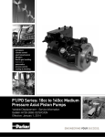
Denison GOLD CUP® Product Catalog
Piston Pumps & Motors
For Open & Closed Circuits
HY28-2667-01/GC/NA,EU
Effective: June 01, 2013
Hydraulic Pump Division and Denison Hydraulics
The Hydraulic Pump Division of Parker Hannifin was formed in 2004 when our significant piston pump business was
expanded through the acquisition of Denison Hydraulics. The addition of Denison allowed us to marry the wealth
of knowledge that both companies have in the design, manufacture, and application of piston products in both open
circuit and closed circuit system applications. Since before WWII, Denison products have been chosen for Military
test stand applications and for shipboard hydraulic applications being recognized as technology leaders.
The heavy duty GOLD CUP® series of pumps and motors in this catalog represent a broadening of our product
offering with hydrostatic transmission applications in marine, drilling, and shredding applications, among others. The
tried and true design of the GOLD CUP® product line incorporates features such as integral servo and replenishing
pump, hot oil shuttle, and a unique servo control system; all of which combine to provide a rugged self contained
package which can withstand the harshest of conditions and continue to perform with trouble free long life.
The division is a leading worldwide manufacturer of hydraulic components and systems for earthmoving and
construction vehicles; for mining equipment; for pulp and paper, chemical and other processing equipment; for
ships and ordnance equipment; and for such in-plant machines as machine tools, plastic molding, die casters, and
stamping presses.
The product information, specifications, and descriptions contained in this publication have been compiled for
the use and convenience of our customers from information furnished by the manufacturer; and we can not,
and do not, accept any responsibility for the accuracy or correctness of any description, calculation, specification, or information contained herein. No such description, calculation, specification, or information regarding the
products being sold has been made part of the basis of the bargain, nor has same created or amounted to an
express warranty that the products would conform thereto. We are selling the goods and merchandise illustrated
and described on this publication on an “as is” basis, and disclaim any implied warranty, including any warranty of
merchantability or warranty of fitness for any particular purpose whatsoever, with respect to the goods and merchandise sold. All manufacturer warranties shall be passed on to our customers, but we shall not be responsible
for special, indirect, incidental, or consequential damages resulting from the use of any of the products or information contained or described on this publication. Further, we reserve the right to revise or otherwise make product
improvements at any time without notification.
WARNING - USER RESPONSIBILITY
FAILURE OR IMPROPER SELECTION OR IMPROPER USE OF THE PRODUCTS DESCRIBED HEREIN OR RELATED ITEMS CAN CAUSE DEATH,
PERSONAL INJURY AND PROPERTY DAMAGE.
This document and other information from Parker-Hannifin Corporation, its subsidiaries and authorized distributors provide product or system options for further investigation
by users having technical expertise.
The user, through its own analysis and testing, is solely responsible for making the final selection of the system and components and assuring that all performance, endurance,
maintenance, safety and warning requirements of the application are met. The user must analyze all aspects of the application, follow applicable industry standards, and follow
the information concerning the product in the current product catalog and in any other materials provided from Parker or its subsidiaries or authorized distributors.
To the extent that Parker or its subsidiaries or authorized distributors provide component or system options based upon data or specifications provided by the user, the user is
responsible for determining that such data and specifications are suitable and sufficient for all applications and reasonably foreseeable uses of the components or systems.
OFFER OF SALE
The items described in this document are hereby offered for sale by Parker-Hannifin Corporation, its subsidiaries or its authorized distributor. This offer and its acceptance
are governed by the provisions stated in the detailed "Offer of Sale" elsewhere in this document.
© Copyright 2013, Parker Hannifin Corporation. All Rights Reserved.
Mining Photo on Front Cover is the Property of Atlas Copco.
2
Hydrostatic Transmission Piston Pumps
GOLD CUP® Series - Open & Closed Circuits
HY28-2667-01/GC/NA,EU
Contents
Contents
Contents .............................................................................................................................................................3
Technical Data ...............................................................................................................................................4
Features ..............................................................................................................................................................7
Description .......................................................................................................................................................8
Pump, Motor Dimensions
P6, 7, 8 ....................................................................................................................................................................10
M6, 7, 8....................................................................................................................................................................14
P11, 14 ....................................................................................................................................................................17
M11, 14....................................................................................................................................................................21
P24, 30 ....................................................................................................................................................................24
M24, 30....................................................................................................................................................................29
Controls Dimensions
10, 2A ................................................................................................................................................................34, 41
2H, 4A......................................................................................................................................................................35
5A, 5C................................................................................................................................................................36, 41
7D, 7J ......................................................................................................................................................................37
7F, 7K ......................................................................................................................................................................38
8A, 8C................................................................................................................................................................39, 42
9A, 9C................................................................................................................................................................40, 42
**4 ............................................................................................................................................................................43
**6, **8, **2 ..............................................................................................................................................................44
Rear Adapters
table .........................................................................................................................................................................45
P6,7,8 .................................................................................................................................................................46-47
P11,14 ..........................................................................................................................................................46, 48-50
P24,30 ................................................................................................................................................................51-54
Inlet Conditions ...........................................................................................................................................55
Performance Curves ...........................................................................................................................56-61
Pump Primary Displacement Control Options...................................................................62-70
Secondary Control Options ............................................................................................................70-71
Hydraulic Schematics ........................................................................................................................72-76
GOLD CUP® Pump Control Combinations...................................................................................77
Pump Ordering Code ...........................................................................................................................78-79
GOLD CUP® Motor Control Combinations ..................................................................................81
Motor Ordering Code ...........................................................................................................................82-83
Offer of Sale ...................................................................................................................................................87
Parker Hannifin Corporation
Hydraulic Pump Division
Marysville, Ohio USA
3
Hydrostatic Transmission Piston Pumps
GOLD CUP® Series - Open & Closed Circuits
HY28-2667-01/GC/NA,EU
Technical Data
Series
Terms P6
Max. displacement in3/rev. 6.00
cm3/rev. 98,3
Pressure
Continuous psi
5000
bar
350
Intermittent psi
60007)
bar
4207)
Speed (Pump)
max. @ full stroke rpm
3000
(Motor )
max. @ full stroke rpm
3000
(Motor )
max. @ 50% stroke rpm
3600
Mounting
Flange -2 bolt SAE
127-2 (C)
Flange -4 bolt (opt. on 6,7 & 8)
SAE
152-4 (D)
Shaft - keyed SAE
32-1 (C)
keyed SAE
44-1 (D)
Shaft - splined SAE
32-4 (C)
splined SAE
44-4 (D)
Weight (Pump) less controls
lbs
175-300
Mass kg.
80-135
Weight (Motor Fixed)
lbs
110
Mass kg.
50
Weight ( Motor Variable) less controls
lbs
110
Mass kg.
50
Rotating inertia
lbs-in2 92
kg.m2
0,027
Torque (Motor) theo. max.
per 100 psi lbs-in
95.5
per 100 bar Nm
157
at 5000 psi lbs-in
4774
at 350 bar Nm
539,5
Power (Motor) theo. max.at 5000 psi, 350 bar
per 100 rpm hp
7.6
kW
5,7
at 2000 rpm hp
151.5
kW
113,0
Torque (Motor) efficiency - approx. stalled % theo. 81
running % theo. 93
Case pressure: max. allowable continuous
psi
bar 5,2
5,2
intermittent psi
125
bar
8,6
(Not to exceed 25 psi,1,7 bar above inlet in open circuit units)
Flow (Pump) theo.at max.displ.@1500 rpm gpm
39
lpm
148
@1800 rpm gpm
47
lpm
178
Displacement
(Internal aux. pump)
P6,7,8P,S,V
in3/rev. 1.07
cm3/rev. 17,5
Flow (Internal aux. pump)
@1500 rpm gpm
6.9
lpm
26,1
@1800 rpm gpm
8.3
lpm
31,4
Displacement
P7
P8
P11
P14
P24
P30
7.25
118,8
5000
350
60007)
4207)
3000
3000
3600
127-2 (C)
152-4 (D)
32-1 (C)
44-1 (D)
32-4 (C)
44-4 (D)
175-300
80-135
110
50
110
50
92
0,027
115.4
189
5769
651,9
8.00
131,1
5000
250
5000
3107)
2100
NA
NA
127-2 (C)
152-4 (D)
32-1 (C)
44-1 (D)
32-4 (C)
44-4 (D)
175-300
80-135
N/A
N/A
N/A
N/A
92
0,027
NA
NA
NA
NA
11.00
180,3
5000
350
60007)
4207)
2400
2400
2800
165-4 (E)
44-1 (E)
44-4 (E)
325-530
145-240
250
110
300
135
290
0,085
175
287
8750
990
14.00
229,5
5000
350
60007)
4207)
2400
2400
2800
165-4 (E)
44-1 (E)
44-4 (E)
325-530
145-240
250
110
300
135
290
0,085
222
362
11100
1250
24.60
403,2
50001)
3501)
55001)7)
3701)7)
21002)
21002)
21002)
177-4 (F)
50-1 (F)
50-4(F)
750-835
340-375
510
230
650
290
821
0,240
392
623
19576
2158
30.60
501,5
50001)
3501)
55001)7)
3701)7)
1800
1800
1800
177-4 (F)
50-1 (F)
50-4 (F)
750-835
340-375
600
270
670
300
977
0,286
487
797
24351
2752
9.2
6,8
183.1
136,6
81
93
75
5,2
125
8,6
NA
NA
NA
NA
NA
NA
75
5,2
125
8,6
13.8
10,3
277.8
207,0
81
93
75
5,2
125
8,6
17.6
13,1
353.5
263,7
81
93
75
5,2
125
8,6
31.1
23,1
621.3
463,5
81
93
75
5,2
125
8,6
38.6
28,8
695
518,2
81
93
75
5,2
125
8,6
47
178
57
216
P11,14P,S
(2) 1.074)
(2) 17,5
(2) 6.9
(2) 26,1
(2) 8.3
(2) 31,4
52
197
62
235
P11,14V
1.075)
17,5
6.9
26,1
8.3
31,4
71
269
86
326
P24P
2.816)
46,1
18.2
68,9
21.9
82,9
91
344
109
413
P24S3)
2.816)
46,1
6.5
24,6
7.8
29,5
160
606
192
727
P30P
2.816)
46,1
18.2
69,1
21.9
82,9
199
753
238
901
P30S3)
2.816)
46,1
6.5
24,6
7.8
29,5
1) Max. pressure 5000 psi, (350 bar) for M24 and 30 series variable motors. Higher servo pressure may be required - consult Parker.
2) On HF-1 fluids, 1800 RPM Max. on HF-0 fluids.
3) Internal cartridge provides servo flow and must be supercharged from external replenishing flow, from external auxiliary pump.
4) One servo cartridge and one replenishing cartridge.
5) Servo cartridge only.
6) Standard, other sizes available, see ordering code.
7) 10% of operation time, not exceeding 6 successive seconds.
4
Parker Hannifin Corporation
Hydraulic Pump Division
Marysville, Ohio USA
Hydrostatic Transmission Piston Pumps
GOLD CUP® Series - Open & Closed Circuits
HY28-2667-01/GC/NA,EU
Technical Data
Replenishing pressure (Internal aux. pump)
Replenish pressure minus case pressure
psi
bar
Servo pressure (Internal aux. pump)
psi
Servo pressure minus case pressure
bar
at 0 psi, 0 bar discharge pressure
Servo pressure (Internal aux. pump) (Above
psi
repl.)
for HI-IQ control units. Servo pressure minus bar
case pressure at 5000 psi, 350 bar discharge pressure -
P6,7,8,11,14,24P
180-220
12,4-15,2
308-420
21,2-29,0
P6,7,8,11,14,24S
* 180-220
12,4-15,2
308-420
21,2-29,0
P30P
180-220
12,4-15,2
308-420
21,2-29,0
P30S
*180-220
12,4-15,2
308-420
21,2-29,0
500-650
500-650
500-650
34,5-44,8
34,5-44,8
34,5-44,8
at system pressure range 0 to 5000 psi, 350 bar.
500-650
34,5-44,8
*Note: Nominal setting, may be increased if required.
Series
Controls
Compensator response
(per SAE J497 @ 5000 psi, 350 bar)
Compensator adjustment
Torque to turn rotary servo shaft
Terms
off-stroke sec.
on-stroke sec.
psi/turn
bar/turn
in.-lbs
Nm
P6
P7
P8
P11
P14
P24
P30
0.05
0.9
2000
138
20
2,3
0.05
0.9
2000
138
20
2,3
0.05
0.9
2000
138
20
2,3
0.07
1.5
2000
138
20
2,3
0.07
1.5
2000
138
20
2,3
0.10
1.8
2000
138
20
2,3
0.10
1.8
2000
138
20
2,3
The maximum inlet at the auxiliary pump inlet is 200 psi. (13,8 bar)
Minimum compensating pressure will always be 100-200 psi. (6,9-13,8 bar) over servo pressure.
Any inlet pressures above atmospheric will increase noise levels and decrease efficiencies noted in this literature. Exact measurements depend
on each application and operating conditions. Please consult your nearest Parker Office for further details.
*Standard factory compensating pressure is 1,000 psi. (69,0 bar).
Parker Hannifin Corporation
Hydraulic Pump Division
Marysville, Ohio USA
5
Hydrostatic Transmission Piston Pumps
GOLD CUP® Series - Open & Closed Circuits
HY28-2667-01/GC/NA,EU
Technical Data
REAR DRIVE TORQUE CAPACITY
FRONT INPUT SHAFT
REAR DRIVE TORQUE CAPACITY
SERIES
SERIES
P6,7,8
P,S,V,X,D
P6,7,8
P,S,V,X,D
P6,7,8
R,L only
P11,14
P,S,V,X
P11,14
R,L only
FRONT IN
PUT SHAFT
TYPE
TORQUE CAPACITY
P6,7,8 TYPE Keyed SAE
32-1(C)CAPACITY 6920Ain-lbs.
TORQUE
P,S,V,X,D
Spline SAE 32-4(C)
(780 Nm)
Keyed SAE 32-1(C)
6920 in-lbs.
Spline SAE 32-4(C)
(780 Nm)
P6,7,8
Keyed SAE 44-1(D)
P,S,V,X,D
Spline SAE 44-4(D)
Keyed SAE 44-1(D)
6920 in-lbs.
(1565 Nm)
Spline SAE 44-4(E)
(1510 Nm)
Spline SAE 44-4(E)
(3020 Nm)
•C
•
•
•
•
••
••
• ••
••
••
B
•
•
•
• in-lbs.
13,845
• Nm)
(1565
•
13,370 in-lbs.
• Nm)
(1510
•
26735 in-lbs.
•
(3020 Nm)
•
•
•
•
•
•
•
•
•
•
•
24350 in-lbs. •
(2750 Nm) •
48,700* in-lbs. •
(5,500 Nm) •
6920 in-lbs.
(780 Nm)
Spline SAE 44-4(D)
(780 Nm)
P6,7,8
Keyed SAE 32-1(C)*
Keyed
SAE 32-1(C)*
13,845 in-lbs.
R,L
only
Spline SAE 32-4C
Spline SAE 32-4C
REAR MOUNTINGS
SAE
RA
EAR MOUNB
TINGS
REAREOUTPUT SH
C
D
F AFT
P11,14
Keyed SAE 44-1(E)
Keyed SAE 44-1(E)
13,370 in-lbs.
P,S,V,X
Spline SAE 44-4(E)
P11,14
Keyed SAE 44-1(E)*
Keyed SAE 44-1(E)*
26735 in-lbs.
R,L only
Spline SAE 44-4(E)
P24,30
P,S,X
P24,30
Keyed SAE 50-1(F)
Keyed SAE 50-1(F)
24350 in-lbs.
P,S,X
Spline SAE 50-4(F)
Spline SAE 50-4(F)
(2750 Nm)
P24,30
R,L only
P24,30
Keyed SAE 50-1(F)
Keyed SAE 50-1(F)
48,700* in-lbs.
Spline
SAE 50-4(F)
(5,500 Nm)
R,L
only
Spline SAE 50-4(F)
SAE
•
•
•
•
•D
•
•
•
•
•
•
•
••
••
•
•
••
••
E
F
REAR OUTPUT SHAFT
TORQUE CAPACITY
1750 in-lbs.
(195 Nm)
TORQUE CAPACITY
1750 in-lbs.
(195 Nm)
1750 in-lbs.
(195 Nm)
1750 in-lbs.
(195 Nm)
•
•
•
•
••
••
•
•
••
••
6920 in-lbs.
(780 Nm)
6920 in-lbs.
(780 Nm)
2400 in-lbs.
(270 Nm)
2400 in-lbs.
(270 Nm)
•
•
••
••
•13,370 in-lbs.
•(1510 Nm)
13,370 in-lbs.
(1510 Nm)
2700 in-lbs.
(305 Nm)
2700 in-lbs.
(305 Nm)
•24,350 in-lbs•
• (2750 Nm)•
24,350 in-lbs
(2750 Nm)
* Coupling for* keyed
shaftfor
must
be pressed
fit forbe
fullpressed
torque capability.
Coupling
keyed
shaft must
fit for full torque capability.
P6/7/8 SAE 127-2
Mtg.,
32-1,
4 Shaft
Bearing
(6007) 230-82140 (6007)
P6/7/8
SAE
127-2
Mtg.,
32-1,230-82140
4 Shaft Bearing
Speed (rpm)
1000 1000
Speed (rpm)
0
0
Shaft Load (lbs) *
S
h
a
f
t
L
o
a
d
(l0bs) * 0
Shaft Load (N) *
*
S
h
a
f
t
L
o
a
d
(
N
)
Case Pressure (psi)
0
25
Case Pressure
Case Pressure (bar)
0.0 (psi)1.7
Case
Pressure
(bar)
B-10 Life (hours x 1000) 8E+08 1833
1000 1000 1200 1200 1200 1200 1500 1500 1500 1500 1800 1800 1800 1800
1000 1000 1000 1000 1200 1200 1200 1200 1500 1500 1500 1500 1800
0
0
0
0
0
0
1000 1000
1000 1000
1000 1000
1000 1000
0
0 0 10000 10404048 44048
00
10000 44140800 44480 0 0 0 10040448 10044048 0
4448 4448
0
0
0
0
0
0
0
4
4
4
8
4
4
4
8
4
4
4
8
4
4
4
8
4
4
4
80 44425
8
0
25
0
25
0
25
0
25
0
25
0
25
25
0
25
0
0.0 0 1.7 25 0.0 01.7
0.0
1.7
0.0
1.70
0.025 1.7 0 0.0 25 1.7 0 0.0 251.7
0.0 5E+08
1.7 1222
0.0 0.518
1.7 0.518
0.0 4E+081.7 1018 0.00.432 1.7
0.7780.00.778 1.7
6E+08 0.0
1528 1.7
0.648 0.648
0.432 0.0
B-10 Life (hours x 1000)
8E+08
1833
0.778 0.778 6E+08
P6/7/8 SAE 152-4 Mtg., 44-1, 4 Shaft Bearing 230-00207-0 (6207)
Speed (rpm)
1000 152-4
1000
P6/7/8 SAE
0
Shaft Load (lbs) *
Speed (rpm)0
0
0
Shaft Load (N) *
Shaft Load (lbs) *
Case Pressure (psi)
0
25
Shaft Load (N) *
Case Pressure (bar)
0.0
1.7
Case Pressure (psi)
B-10 Life (hours x 1000) 3E+09 7394
Case Pressure (bar)
1528
0.648 0.648 5E+08
1000 44-1,
1000 4 1200
1200 1200
1200 1500(6207)
1500
Mtg.,
Shaft Bearing
230-00207-0
0
0
1000 1000
1000 1000
1000 10000 10000 1000
1200 1200
1200
0
0
0
0
4448 4448
4448 4448
0
0
0
0
1000 1000
1000
0
25
0
25
0
25
0
25
0
0
0
0
4448 4448
4448
0.0
1.7
0.0
1.7
0.0
1.7
0.0
1.7
0
25
0
25
0
25
0
3.136 3.136 3E+09 6161 2.613 2.613 2E+09 4929
0.0
1.7
0.0
1.7
0.0
1.7
0.0
1500
1000
1200
4448
1000
0
4448
0.0
25
2.09
1.7
1222
1500 1800 1800 1800 1800
1000
1000 1000
1500 0 1500 0 1500
1500 1800
0
0
4448
4448 4448
0
0
0
1000 1000
25
0
25
0
25
0
0
0
4448 4448
1.7
0.0
1.7
0.0
1.7
0
25
0
25
0
2.09 2E+09 4170 1.742 1.742
0.0
1.7
B-10 Life
(hours
7394 230-82148-0
3.136 3.136(6010)
3E+09(2 &
6161
2.613
2.613 2E+09 4929
P11/14 SAE 165-4
Mtg.,
44-1,x 41000)
Radial 3E+09
Shaft Bearing
3 Shaft
Codes)
Speed (rpm)
1000 1000
Shaft Load (lbs) *P11/14 SAE
0 165-4
0
Shaft Load (N) * Speed (rpm)0
0
Case Pressure (psi)
0
Shaft Load (lbs)
* 25
Case Pressure (bar)
0.0
1.7
Shaft Load (N) *
B-10 Life (hours x 1000) 2E+09 535
Case Pressure (psi)
1000
1000
1200
1200
1200
1200
1500
1500
1500
1800
0
0
25
1.7
0.518 0.518 4E+08 1018
1500
1800
0.0
2.09
1800
1.7
2.09
1800
0
0
25
0.0
1.7
2E+09 4170
1800
1000
0
4448
4448 1500
4448 1800
1200
1200 4448
1500 0 1500 0 1500
25
0
25 0
0 0 25 10000 1000
25
1000
1000
0
1.7
0.0
1.7
0.0
1.7
0.0
1.7
4448 4448
0
0
4448 4448
0
356 1.272 1.272 1E+09 297
1.06 1.06
1800
4448 1200
4448 1200
0
44481000
444810000 10000 1000
0 0 25 0 0 1000
25 1000
0
25
00
0
0.0
1.7
0.0
1.7
0.0
1.7
0.0
0
0
4448 4448
0
0
1.907 1.907 2E+09 446 1.589 1.589 1E+09
0
25
0
25
0
25
0
25
0
25
0
25
0
1.7
0.0
1.7
0.0
1.589 1500
1.589 1500
1E+09180035618001.272
1500
18001.272
1800 1E+09
B-10 Life (hours
1000) 1000
2E+09
446
Speed (rpm)
1000 x1000
1000 535
1200 1.907
1200 1.907
1200 2E+09
1200 1500
Shaft Load (lbs) *
0
0
1000 1000
0
0
1000 1000
0
0
1000 1000
0
0
1000 1000
230-82214-0
(22208)
Shaft Load (N) * P11/14 SAE
0 165-4
0 Mtg.,
4448 44-1,
4448 4 Spherical
0
0 Roller
4448 Shaft
4448 Bearing
0
0
4448 4448
0 (7 &
0 8 Shaft
4448 Codes)
4448
Case Pressure (psi)
25
0 100025 10000 1000
25 1000
0
25
0
25
0
251500 0 1500 25 15000 1500
25 1800
Speed (rpm)0
1200
1200
1200
1200
Case Pressure (bar)
0.0 0 1.7 0 0.0 1000
1.7 1000
0.0
1.7
0.0
1.7
1.7
Shaft Load 0.0
(lbs) * 1.7
0
0
1000 0.0
1000 1.7 0 0.0 0 1.7 10000.0 1000
0
B-10 Life (hours xShaft
1000)Load16856
2043 4448
230
143
11237
1635
95.7 0
(N) * 2452 275 0 172 0140464448
0
0
4448 184
4448 114.80 9364 0 13634448153 4448
0
0.0
25
1.7
0
0.0
25
1.7
P24 SAE 177-4 Mtg., 50-1, 4 Shaft Bearing 230-82213-0 (22311)
0
0.0
Speed (rpm)
1000 1000 1000 1000 1200 1200 1200 1200
x 1000)
16856
172
Shaft Load (lbs) *B-10 Life (hours
0
0
1000
100024520 2750
1000 14046
1000
Shaft Load (N) *
0
0
4448 4448
0
0
4448 4448
P24 SAE 177-4
Mtg.,
50-1,
425Shaft0Bearing
Case Pressure (psi)
0
25
0
25 230-82213-0
0
25
Speed (rpm)0.0
Case Pressure (bar)
1.7
0.010001.7 10000.0 1000
1.7 1000
0.0 1200
1.7
(lbs) *428.5 276.7 0 213.5 0 493 1000
0
B-10 Life (hours xShaft
1000)Load591.6
357 1000
230.5 178
Shaft Load (N)
*
1800 1800
1000 1000
4448 4448
0
25
0.0
1.7
1.742 1.742
1000 44-1,
1000 4 Radial
0
0
1000
1000230-82148-0
0
0 (6010)
1000 (2
1000
0
0
1000
Mtg.,
Shaft
Bearing
& 3 Shaft
Codes)
Case Pressure (bar)
0.0
0.0
1.7
0.0
1.7
0.0
1.7
0.0
P11/14 SAE 165-4
Mtg., 44-1, 4 Spherical
Roller1.7
Shaft Bearing
230-82214-0
(22208)
(7
& 8 Shaft
Codes)
Case Pressure (psi)
Case Pressure (bar)
1800 1800
1000 1000
4448 4448
0
25
0.0
1.7
0.432 0.432
0
0
4448
4448
P30 SAE 177-4Case
Mtg.,
50-1, 4(psi)
Shaft Bearing0 230-82213-0
(22311)
Pressure
25
0
25
0
0
1200
0.0
1000
493
25
1.7
0
0.0
1500 1500
2043
230
0
0
0
0
(22311)
0
25
1200
1200
0.0
1.7
0
1000
394.4
991.6
0
25
1500
1.7
0
357
25
1.7
0
0.0
25
1.7
0
0.0
25
1.7
0
0.0
1500 1500 1800 1800 1800 1800
143 1000
11237 0 1635 0 1841000114.8
1000
1000 9364
4448 4448
0
0
4448 4448
0
25
0
25
0
25
1200 1.71500 0.015001.7 15000.0 1500
0.0
1.7 1800
1000 142.30 328.7 0 2381000
184.4
153.71000
118.6 0
4448 4448
0
0
4448 4448
0
0
25
0
25
0
25
0
1500
1800 0.0
0.0 1500
1.7 15000.0 18001.7 1800 0.01800 1.7
0
1000 1000
0
0
1000 1000
230.5 178 394.4 991.6 184.4 142.3 328.7
Speed (rpm)
1000(bar)
1000 10000.01000 1.71200 0.0
1200 1.7
1200
Case Pressure
Shaft Load (lbs) *
0
0
1000 1000
0
0
1000
B-10 Life (hours x 1000)
591.6 428.5 276.7 213.5
Shaft Load (N) *
0
0
4448 4448
0
0
4448 4448
0
0
4448
Case Pressure (psi)
0
25
0
25
0
25
0
25
0
25
0
P30
SAE
177-4
Mtg.,
50-1,
4
Shaft
Bearing
230-82213-0
(22311)
Case Pressure (bar)
0.0
1.7
0.0
1.7
0.0
1.7
0.0
1.7
0.0
1.7
0.0
1000
1200 118.4
1200 84.2
1200
B-10 Life (hours xSpeed
1000)(rpm)
227 177.7 126.4
102.81000
189.21000
148 1000
105.3 1200
85.6 151.3
4448
0
0
4448 4448
25
0
25
0
25
1.7
1.7
0.0
1.7
0.0
1500126.1
150098.71500
68.5
70.2 1500
57.1 1800
Shaft Load (lbs) *
0
0
1000 1000
0
0
1000 1000
0
0
*radial load at center of key or spline
Shaft Load (N) *
0
0
4448 4448
0
0
4448 4448
0
0
Note: VariationCase
in lifePressure
is due to
variations in 0tolerances
(psi)
25 within
0 the pump.
25
0
25
0
25
0
25
Contact Case
Parker
Hydraulics
and with1.7
other case
values.
Pressure
(bar) for B-10 with
0.0 other
1.7operating
0.0 conditions
1.7
0.0
0.0 pressure
1.7
0.0
1.7
Consult Parker Hydraulics for shaft side loads of P*R units.
B-10 Life (hours x 1000)
227 177.7 126.4 102.8 189.2 148 105.3 85.6 151.3 118.4
1000
4448
0
0.0
84.2
1000
4448
25
1.7
68.5
0
0
0
0.0
126.1
1800
0
0
25
1.7
297
1800
1000
4448
0
0.0
1.06
1800
1000
4448
25
1.7
1.06
1800
0
0
25
1.7
1363
1800
1000
4448
0
0.0
153
1800
1000
4448
25
1.7
95.7
1800
0
0
25
1.7
238
1800 1800
1000 1000
4448 4448
0
25
0.0
1.7
153.7 118.6
1800
0
0
25
1.7
98.7
1800
1000
4448
0
0.0
70.2
1800
1000
4448
25
1.7
57.1
*radial load at center of key or spline
Note: Variation in life is due to variations in tolerances within the pump.
Contact Parker Hydraulics for B-10 with other operating conditions and with other case pressure values.
Consult Parker Hydraulics for shaft side loads of P*R units.
6
Parker Hannifin Corporation
Hydraulic Pump Division
Marysville, Ohio USA
Hydrostatic Transmission Piston Pumps
GOLD CUP® Series - Open & Closed Circuits
HY28-2667-01/GC/NA,EU
Features
1
Quick change valve block - easy to
service or replace
10
Auxiliary pump can be changed without
disassembling the transmission
2
Quick change controls - easy to
service and change
11
Standard SAE keyed or splined drive
shafts are available
3
Dampened low inertia rocker cam more stable, quieter and faster than
other designs
12
4
Exclusive zero-backlash rotary servo
design - lifetime accuracy
5
Field adjustable compensator override easily adjusted without removing from
machinery
6
7
8
High pressure mechanical shaft seals
can be changed without disassembling
the transmission. Double lip seals are also
available
13
One piece stroking vane/cam means no
lost motion, zero backlash, better control,
and no linkages to wear out
14
Stroking vane seals are pressure loaded
for longer life
Precision barrel bearing, a distinctive
Denison Hydraulics feature for over 30
years - permits high speeds, high
pressure and provides long life
Note:
15
Standard compensator vent ports allow
for a wide variety of controls (See
Applications Manual)
16
Rocker cam displacement indicator helps
troubleshoot the system
17
Modulated servo pressure saves power
18
Standard Code 62 SAE split flange
connections
19
Conforms to SAE mounting standards.
20
Fast compensator response. See page 5.
21
Variable motors available for multiple
speed ranges or constant power
1. These products, with exception of 8 cubic inch units, are qualified to
meet Military specifications MIL-P-17869A and MIL-S-901-C Grade A.
2. All GOLD CUP® Pumps and Motors* have ATEX approval.
*See ordering code for availability.
Versatile controls - can be located on
either side of pump or motor for
maximum freedom of design
3. Consult factory for other approvals such as ABS and Lloyd's Registry.
Ring style replenishing checks fastest
operation with
no sliding
poppets
or parts
and low
pressure drop
or parts and low pressure drop
19
Hot oil shuttle available - fast, reliable
operation
Hot oil shuttle
available - fast, reliable
19
9
9
operation
6
21
611
1821
12
5
20
1
15
17
2
10
7
18
6
8
16
3
4
12
13
2
11
7
14
19
Parker Hannifin Corporation
Hydraulic Pump Division
Marysville, Ohio USA
7
Hydrostatic Transmission Piston Pumps
GOLD CUP® Series - Open & Closed Circuits
HY28-2667-01/GC/NA,EU
Description
CLOSED HYDRAULIC CIRCUIT
Variable Pump/Fixed Motor. This combination provides for a constant torque
output at a fixed maximum pressure over the full speed range. Speed and
direction are controlled with a variable displacement over-center pump. Power
from overhauling loads is regenerated back into the pump prime mover. Motor
speed is limited to the maximum speed permitted by full pump displacement.
System is capable of full power only at maximum pump displacement.
POWER CHARACTERISTICS OF
HYDROSTATIC TRANSMISSIONS
Variable Pump/Variable Motor. This combination provides for an extended range
of motor speeds. The motor, at full displacement, delivers maximum torque while
its speed and direction respond to displacement changes of the crossover center
pump. Power is proportional to motor speed.
This transmission system has the capability of constant torque and rising power
until the pump reaches full displacement and full power at elevated speeds as
motor displacement and torque are reduced.
PACKAGE PUMP
The package pump contains the circuit elements shown in the hydraulic
schematic on pgs. 72-74. These include the axial piston over-center variable
displacement pump which controls the speed and direction of the motor, the
auxiliary pump which supplies servo pressure (for controlling the displacement
of the variable pump) and replenishment pressure, the servo pressure relief
valve, the replenishment pressure relief valve and the replenishment check
valves for ports A and B. The pump package also includes the displacement
control valves as well as an external arm which shows actual displacement.
The various control features are described below.
PACKAGE MOTOR
The package motor, shown in schematic pgs. 72-74, contains the axial piston
fluid motor, the shuttle valve that continuously removes hot oil from the low
pressure side of the loop and a relief valve to establish minimum hydraulic loop
pressure at the motor. The fluid motor is available with fixed displacement or
with the variable displacement option. The standard variable motors include an
external indicator which shows displacement.
OPEN CIRCUIT PUMP
The open circuit pump contains the circuit elements shown on pages 75,76.
These include a cross-center variable displacement pump which is normally
limited to one side of center. The auxiliary pump supplies only servo pressure
to control the main pump displacement and inlet porting is enlarged to improve
the pump’s inlet characteristics. As the open loop pump operates on one side of
center only, not all controls are available.
AUXILIARY REAR DRIVE
Additional auxiliary flow is available with the rear drive pump option. The rear
drive may also be utilized for servo and other purposes. See ordering code for
additional detail.
“R” & “L” style pumps have no rear shaft seal, so any pump driven must be able
to withstand case pressure of the pump driving it.
AUXILIARY PUMP
Integral to the package pump’s envelope is the gerotor auxiliary pump.
(P24P, P24S, P30P & P30S have vane integral pump). It provides servo
and replenishing pressure. See page 5 for factory settings.
NOTE: Auxiliary pump inlet must be connected directly to the reservoir.
Customer must supply external line from integral auxiliary pump back into
main pump for filtering servo and/or replenishing oil.
(see installation drawings starting on pg 10.)
8
Parker Hannifin Corporation
Hydraulic Pump Division
Marysville, Ohio USA
Hydrostatic Transmission Piston Pumps
GOLD CUP® Series - Open & Closed Circuits
HY28-2667-01/GC/NA,EU
Description
MOUNTING
The pump or motor is designed to operate in any position. For vertical mounting
it is recommended that the shaft bearing be drained via the drain port provided.
The mounting hub and mounting flange are in full conformance with SAE
standard. The shaft must be in alignment with the shaft of the driven load and
should be checked with a dial indicator. The mounting pad or adapter into which
the fluid pump pilots must be concentric with the pump shaft within 0.006 in.,
0,152 mm to prevent bearing failure. This concentricity is particularly important if
the shaft is rigidly connected to the driving load without a flexible coupling. The
shaft-coupling interface must be lubricated with lithium molydisulfide or similar
grease.
INLET PRESSURES,
PORTS A & B
In a closed hydraulic loop the pump inlet or the fluid motor inlet (during dynamic
braking) are supercharged by the integral replenishment system. Consult Parker
in cases where fluid viscosity or dynamics or line size may cause inlet pressure
at either port A or B to be less than the 150 psi, 10,3 bar maintained by the
integral replenishment system. For operation in open loop or combination openclosed loops, consult Parker.
DRAIN PORT
Drain the package pump from the higher drain port. If drain port is above the
fluid level in the tank install a 5 psi, 0,3 bar relief of suitable size in the drain
line to tank. For vertical mounting it is recommended that the shaft bearing be
drained via the drain port provided.
For pump speeds intermittently below 1000 rpm, install a back pressure relief 40
psi, 2,8 bar of suitable size in the drain line from the higher port to tank. Motor
case drain must be connected to pump case.
Motor: Drain the motor from the higher drain ports into the lower pump drain port
or tank. Make provision that the motor drain port pressure will not exceed the
maximum limits specified above.
RETURN LINE FILTER
Relatively inexpensive low pressure filters are recommended for installation
in the return lines and drain lines from circuits using these pumps or motors.
Consider the possibility of decompression surges and intensified flow in cylinder
circuits as well as the factors above in selecting return line filters.
AUXILIARY FLOW FILTERS
It is recommended the auxiliary pump fluid be filtered to aid in maintaining
acceptable cleanliness levels. For good filtration and reasonable maintenance
intervals the filter capacity must be at least twice the auxiliary pump flow. To use
this feature, install the isolation plug and connect the filter between ports G&H,
(P6,P7,P8,P24,P30), or J&K (P11,P14). See detailed schematics and drawings
pages 10-22 for location of these ports.
RECOMMENDED FLUIDS
The fluid recommended for use in these pumps and motors has a petroleum
base and contains agents which provide oxidation inhibition and anti-rust,
antifoam and de-areating properties as described in Parker Denison standard
HF-1. These preferred fluids do not contain anti-wear additives. Fluids containing
anti-wear additives that meet Parker Denison standard HF-0 are acceptable.
VISCOSITY
Max. at cold start
7500 SUS, 1600 cSt
at low pressure, low flow and if possible, low speed
Max. at full power
750 SUS, 160 cSt
Optimum for max. life
140 SUS, 30 cSt
Minimum at full power
60 SUS, 10cSt
CLEANLINESS
Particle contamination to meet ISO 20/17/14 or better. Water content < 500 ppm
for mineral based fluids. For detail on fluid recommendations see bulletin
SPO-AM305.
Parker Hannifin Corporation
Hydraulic Pump Division
Marysville, Ohio USA
9
Hydrostatic Transmission Piston Pumps
GOLD CUP® Series - Open & Closed Circuits
HY28-2667-01/GC/NA,EU
P6-P7-P8F, M Dimensions
6000 PSI
1.50
DIA.
(414 BARS)
(38,1)
4-BOLT FLG. CONN.
SAEDRAIN CONN.
SAE-12 STR. THD.
D1
L3
A
.72
(18,3)
3.00
(76,2)
.84
(21,3)
3.00
(76,2)
"D" CASE DRAIN CONN.
SAE-12 STR. THD.
B
A
1.56
(39,6)
1.53
(38,9)
3.06
(77,7)
3.12
(79,2)
A
D2 ALT. DRAIN CONN.
SAE-12 STR. THD.
L4
1.44
(36,6)
L2
1.30
5/8-11UNC x
DEEP
(33,0)
4-PLACES
L1
MOUNTING
MOUNTING
P*F
SAE 127-2
(SAE-C)
127-2
SAE
SAE 152-4
(SAE-C)
(SAE-D)
SAE 152-4
(SAE-D)
P*M
A
L1
L1 L2 L2L3
L4
L3
3000 PSI
2.00
DIA.
(207 BARS)
(50,8)
4-BOLT FLG. CONN.
SAE-
L4
11.19
(284,2)
11.19
11.06
4.90
(280,9)
11.06(124,5)
.85
(21,6)
4.90
11.59
(284,2)
11.46 (280,9)
5.30
(291,1)
(134,6)
.89
(124,5)
.85
(21,6)
11.46
(291,1)
5.30
(134,6)
.89
(22,6)
(294,3)
11.59
(294,3)
(22,6)
DRAIN CONN.
SAE-12 STR. THD.
D1
L3
1.68
(42,7)
1.05
1/2 -13UNC x
DEEP
(26,7)
4-PLACES
1.30
5/8-11 UNC-2B TAP x
(33,0)
4 PLACES AS SHOWN
DP.
3.12
(79.2)
1.56
(39.6)
3.94
(99,9)
.25
(6.4)
3.94
(99,9)
.72
(18.3)
1.44
(36.6)
SYSTEM PORT A (FAR SIDE)
SYSTEM PORT B (NEAR SIDE)
1.50 DIA. 6000 PSI
(418 BARS)
(38.1)
4-BOLT FLG. CON
SAE-
A
D2 ALT. DRAIN CONN.
SAE-12 STR. THD.
L4
L2
L1
MOUNTING
4.50
(114,3)
MOUNTING
L1
SAE 127-2
SAE
127-2
(SAE-C)
13.40
(340,4)
SAE 152-4
13.80
(350,5)
(SAE-C)
(SAE-D)
SAE
152-4
(SAE-D)
4.50
(114,3)
10
L1
L2
10.14
13.40
(257,6)
(340,4)
10.54
(267,7)
13.80
(350,5)
L3L2 L4
4.90
10.14 .85
(124,5)
(21,6)
L3
L4
(257,6)
4.90
(124,5)
.85
(21,6)
(267,7)
5.30
(134,6)
.89
(22,6)
.89
5.30
(134,6)
10.54 (22,6)
NOTE: See page 16 for shaft information.
See pages 45-54 for rear drive information.
Parker Hannifin Corporation
Hydraulic Pump Division
Marysville, Ohio USA
Hydrostatic Transmission Piston Pumps
GOLD CUP® Series - Open & Closed Circuits
HY28-2667-01/GC/NA,EU
P6-P7-P8V, D, P Dimensions (Less Controls)
H AUXILIARY PUMP (FAR SIDE)
FILTER RETURN PORT
SAE-8 STR. THD.
(NEAR SIDE) AUXILIARY PUMP OUTLET G
TO EXTERNAL FILTER & SERVO GAGE CONN.
SAE-8 STR. THD.
4.50
(114,3)
L1
A
ALT. DRAIN CONN.
SAE-12 STR. THD.
D1
L3
.72
(18,3)
K AUXILIARY REPLENISH PORT
SAE-16 STR. THD.
4.50
(114,3)
3.00
(76,2)
3.00
(76,2)
B
A
.84
(21,3)
L7
5.27
(133,9)
3.87
TYP.
(98,3)
1.53
(38,9)
1.56
(39,6)
3.06
(77,7)
3.12
(79,2)
3.70
(93,9)
L4
P*V
ALT. DRAIN CONN. D2
SAE-12 STR. THD.
P*V
BG THIS SIDE
AG FAR SIDE
MAIN LOOP GAGE CONN.
SAE-6 STR. THD.
L1
MOUNTING
L2
L2
L3
SAE 127-2
(SAE-C)
15.51
(393,9)
13.70
(348,0)
7.02
(178,3)
SAE 152-4
(SAE-D)
16.85
(427,9)
15.04
(382,1)
8.36
(212,3)
PORT "A"
2.00 DIA. 3000 PSI
(207 bar)
(50,8)
4-BOLT FLG. CONN
SAE-
L3
L1
MOUNTING
P*D & P*P
6.0 & 7.25 GOLD CUP®
TABLE 1
TABLE 1
L4
L4
L5
L7
L5
L7
1.00
(25,4)
10.64
(270,3)
5.15
(130,9)
.86
(21,8)
11.98
(304,3)
6.49
(164,8)
H AUXILIARY PUMP (FAR SIDE)
FILTER RETURN PORT
SAE-8 STR. THD.
(NEAR SIDE) AUXILIARY PUMP OUTLET G
TO EXTERNAL FILTER & SERVO GAGE CONN.
SAE-8 STR. THD.
4.50
(114,3)
L1
ALT. DRAIN CONN.
SAE-12 STR. THD.
D1
L3
1/2-13UNC x 1.05
4-PLACES (26,7)
1.38
5/8-11UNC x
DEEP
(35,1)
4-PLACES
6000 PSI
1.50
DIA.
(38,1)
(414 bar)
4-BOLT FLG. CONN
SAE-
C AUXILIARY PUMP INLET
SAE-16 STR. THD.
A
(42,7)
PORT "B"
L2
A
1.68
1.44
(36,6)
L5
.72
(18,3)
K AUXILIARY REPLENISH PORT
SAE-16 STR. THD.
4.50
(114,3)
3.00
(76,2)
3.00
(76,2)
B
A
.72
(18,3)
L7
5.27
(133,9)
3.87
TYP.
(98,3)
1.56
(39,6)
1.56
(39,6)
3.12
(79,2)
3.12
(79,2)
3.70
(93,9)
L4
1.44
(36,6)
L5
L2
A
ALT. DRAIN CONN. D2
SAE-12 STR. THD.
Parker Hannifin Corporation
Hydraulic Pump Division
Marysville, Ohio USA
C AUXILIARY PUMP INLET
SAE-16 STR. THD.
6000 PSI
1.50
DIA.
(38,1)
(414 bar)
4-BOLT FLG. CONN
TYP. PORTS "A" & "B"
SAEBG THIS SIDE
AG FAR SIDE
MAIN LOOP GAGE CONN.
SAE-6 STR. THD.
11
1.44
(36,6)
1.38
5/8-11UNC x
DEEP
8-PLACES (35,1)
NOTE: See page 16 for shaft information.
See appropriate controls mounting starting on page 34.
Hydrostatic Transmission Piston Pumps
GOLD CUP® Series - Open & Closed Circuits
HY28-2667-01/GC/NA,EU
P6-P7-P8X, R Dimensions (Less Controls)
(NEAR SIDE) AUXILIARY PUMP OUTLET G
TO EXTERNAL FILTER & SERVO GAGE CONN.
SAE-8 STR. THD.
H AUXILIARY PUMP (FAR SIDE)
FILTER RETURN PORT
SAE-8 STR. THD.
K AUXILIARY REPLENISH AND
PUMP FILTER RETURN PORT
SAE-12 STR. THD.
L6
A
SYSTEM PORT A (FAR SIDE)
SYSTEM PORT B (NEAR SIDE)
ALT. DRAIN CONN.
SAE-12 STR. THD.
D1
L3
5.38
(136,5)
5.38
(136,5)
SEE DETAIL "A"
L7
5.27
(133,9)
3.87
(98,3)
.90
(23,0)
3.70
(93,9)
3.38
(85,8)
1.31
5/8 -11UNC-2B THREAD x
DEEP
(33,3)
8-PLACES
.72
(18,3)
L5
L2
A
R
1.44
(36,6)
ALT. DRAIN CONN. D2
SAE-12 STR. THD.
L4
L1
1.56
(39,7)
C AUXILIARY
PUMP INLET
C AUXILIARY
PUMP INLET
SAE-16
STR. THD.
SAE-16 STR.
THD.
3.13
(79,4)
TABLE 3
TABLE 3
MOUNTING
L1
MOUNTING
P*X
A
B
.90
(23,0)
3.87
(98,3)
SAE 127-2
(SAE-C)
17.27
(438,6)
SAE 152-4
(SAE-D)
18.61
(472,6)
L2
SAE 127-2
(SAE-C)
SAE 15.14
152-4
(SAE-D)
(384,6)
L1
L2
17.27
(438,6)
15.14
(384,6)
L3
18.61 7.02 16.48
(472,6)
(178,3)(418,6)
16.48
(418,6)
8.36
(212,3)
P*R
L3
L4
7.02
(178,3)
1.00
8.36
(212,3)
(25,4)
.86
(21,8)
L4
L5
1.00
(25,4)
10.64
(270,3)
L5
L6
L7
16.58
(421,2)
5.15
(130,9)
L6
L7
5.15
6.49
(164,8)
(130,9)
10.64 11.98 16.58
17.92
.86
(455,2)
(21,8)
(270,3) (304,3)(421,2)
11.98
(304,3)
17.92
(455,2)
SYSTEM PORT A (FAR SIDE)
SYSTEM PORT B (NEAR SIDE)
6.49
(164,8)
1.50 DIA. 6000 PSI
(414 BARS)
(38,1)
4 BOLT FLG. CONNECTION
4-BOLT
SAE-
1.30
5/8-11 UNC-2B TAP x
(33,0)
4 PLACES AS SHOWN
D1 DRAIN CONN.
SAE-12 STR. THD.
L1
A
DP.
3.12
(79.2)
1.56
(39.6)
L3
L7
.72
(18.3)
1.44
(36.6)
6.07
(154,1)
.25
(6.3)
3.87
(98,3)
SYSTEM PORT A (FAR SIDE)
SYSTEM PORT B (NEAR SIDE)
1.50 DIA. 6000 PSI
(418 BARS)
(38.1)
4-BOLT FLG. CON
SAE3.87
(98,3)
L4
ALT. DRAIN CONN. D2
SAE-12 STR. THD.
L1
L2
L3
L5
L6
L7
SAE 127-2
(SAE-C)
15.51
(393,9)
11.88
(301,8)
7.02
(178,3)
1.00
(25,4)
10.64
(270,3)
15.14
(384,6)
5.15
(130,9)
SAE 152-4
(SAE-D)
16.85
(427,9)
13.22
(335,9)
8.36
(212,3)
.86
(21,8)
11.98
(304,3)
16.48
(418,7)
6.49
(164,8)
MOUNTING
REAR ADAPTER
L2
L6
B1 SYSTEM GAGE CONN.
SAE-6 STR. THD.
K REPLENISHING PORT INLET
SAE-16 STR. THD.
TABLE 2
4.50
(114,3)
G CONTROL PRESSURE INLET
SAE-8 STR. THD.
A1 SYSTEM GAGE CONN.
SAE-6 STR. THD.
4.50
(114,3)
4.50
(114,3)
6.02
(152,8)
12
(418 BARS)
(38.1)
4-BOLT FLG. CON
L1
L2
L3
L5
L6
L7
SAE 127-2
(SAE-C)
15.51
(393,9)
11.88
(301,8)
7.02
(178,3)
1.00
(25,4)
10.64
(270,3)
15.14
(384,6)
5.15
(130,9)
SAE 152-4
(SAE-D)
16.85
(427,9)
13.22
(335,9)
8.36
(212,3)
.86
(21,8)
11.98
(304,3)
16.48
(418,7)
6.49
(164,8)
MOUNTING
4.50
(114,3)
L4
H SERVO GAGE CONN.
SAE-4 STR. THD.
L5
A
TABLE 2
3.70
(94,0)
L4
NOTE: See page 16 for shaft information.
See pages 45-54 for rear drive information.
See appropriate controls mounting starting on page 34.
Parker Hannifin Corporation
Hydraulic Pump Division
Marysville, Ohio USA
Hydrostatic Transmission Piston Pumps
GOLD CUP® Series - Open & Closed Circuits
HY28-2667-01/GC/NA,EU
P6-P7-P8S, L Dimensions (Less Controls)
(NEAR SIDE) AUXILIARY PUMP OUTLET G
TO EXTERNAL FILTER & SERVO GAGE CONN.
SAE-8 STR. THD.
H AUXILIARY PUMP (FAR SIDE)
FILTER RETURN PORT
SAE-8 STR. THD.
L6
A
ALT. DRAIN CONN.
SAE-12 STR. THD.
D1
L3
"BG" SYS. GAGE (N.S.)
"AG" SYS. GAGE (F.S)
SAE-6 STR. THD.
L7
5.27
(133,9)
3.87
(98,3)
SYSTEM PORT A (FAR SIDE)
SYSTEM PORT B (NEAR SIDE)
SEE DETAIL "A"
1.31
5/8 -11UNC-2B THREAD x
(33,3)
8-PLACES
3.87
(98,3)
DEEP
1.44
(36,6)
3.70
(93,9)
.72
(18,3)
6.51
(165,4)
ALT. DRAIN CONN. D2
SAE-12 STR. THD.
L4
1.56
(39,7)
L5
3.13
(79,4)
C AUXILIARY PUMP INLET
SAE-16 STR. THD.
A
L2
L1
DETAIL "A"
SYSTEM PORTS A & B
1.50 DIA. 6000 PSI
SAE(414 BARS)
(38,1)
4-BOLT FLG. CONNECTION
4.50
(114,3)
5.38
(136,5)
TABLE 5
TABLE 5
MOUNTING
L1
19.97
SAE 127-2
MOUNTING
(SAE-C)
(507,3)
SAE 152-4
SAE
127-2 21.31
(SAE-D)
(541,3)
4.50
(114,3)
5.38
(136,5)
P*S
ALT. DRAIN CONN.
SAE-12 STR. THD.
D1
L1
(SAE-C)
(507,3)
SAE 152-4
(SAE-D)
21.31
(541,3)
L3
L4
7.02
(178,3)
L2
1.00
(25,4)
8.36
15.14.86
(212,3)
(21,8)
L5
L6
L7
16.58
(421,2)
L4
L5
L6
L7
(178,3)
6.49
1.00
(164,8)
(25,4)
10.64
(270,3)
16.58
(421,2)
5.15
(130,9)
8.36
(212,3)
.86
(21,8)
11.98
(304,3)
17.92
(455,2)
6.49
(164,8)
L3
L4
L3
10.64
(270,3)
11.98
7.02 17.92
(455,2)
(304,3)
(384,6)
16.48
(418,6)
5.15
(130,9)
"D3" DRAIN CONNECTION
SAE-16 STR. THD.
"KA" SHUTTLE
RELIEF INLET
SAE-12 STR. THD.
P*L
L2
15.14
(384,6)
16.48
19.97
(418,6)
G SERVO PRESSURE INLET
SAE-8 STR. THD.
K AUXILIARY REPLENISH AND
PUMP FILTER RETURN PORT
SAE-12 STR. THD.
A
L5
REAR ADAPTER
L3
L7
5.27
(133,9)
3.87
TYP.
(98,3)
1.44
(36,6)
.72
(18,3)
2.04
(51,8)
1.56
(39,7)
3.13
(79,4)
7.38
(187,6)
1.31
5/8 -11UNC-2B THREAD x
(33,3)
8-PLACES
SYSTEM PORT A (FAR SIDE)
SYSTEM PORT B (NEAR SIDE)
L4
ALT. DRAIN CONN. D2
SAE-12 STR. THD.
DEEP
1.50 DIA. 6000 PSI
SAE(414 BARS)
(38,1)
4-BOLT FLG. CONNECTION
A
L2
L1
"D3" DRAIN CONNECTION
SAE-16 STR. THD.
TABLE 4
"KA" SHUTTLE RELIEF INLET
SAE-12 STR. THD.
L6
L7
16.58
10.58
(178,3)(421,2)
(268,8)
L7
1.00
5.15
(25,4)
(130,9)
L5
7.02
1.00
15.14
(446,6) (178,3)(384,6)
(25,4)
(384,6)
L57.02 L6
17.58
SAE 127-2
(SAE-C) (446,6)
(SAE-C)
10.58
(268,8)
16.58
(421,2)
5.15
(130,9)
SAE 152-4
SAE
152-4 18.92
(SAE-D)
(480,6)
18.92
(418,6)
(480,6)
16.48
11.92
8.36 17.92
(455,2)
(302,8)
6.49
.86
(164,8)
(21,8)
11.92
(302,8)
17.92
(455,2)
6.49
(164,8)
TABLE
4
MOUNTING
MOUNTING
SAE 127-2
4.50
(114,3)
5.38
(136,5)
(SAE-D)
L1
L1
L2
17.58
L2
L315.14L4
8.36
16.48.86
(212,3)
(21,8)
(418,6)
(212,3)
5.32
(135,1)
NOTE: See page 16 for shaft information.
See pages 45-54 for rear drive information.
See appropriate controls mounting starting on page 34.
5.32
(135,1)
4.50
(114,3)
5.38
(136,5)
Parker Hannifin Corporation
Hydraulic Pump Division
Marysville, Ohio USA
13
Hydrostatic Transmission Piston Pumps
GOLD CUP® Series - Open & Closed Circuits
HY28-2667-01/GC/NA,EU
M6-M7-M8 F, G, M, N Dimensions
M*F & M*G
DRAIN CONN.
SAE-12 STR. THD.
D1
L3
A
L1
L2
L3
SAE 127-2
(SAE-C)
11.19
(284,2)
11.06
(280,9)
4.90
(124,5)
.85
(21,6)
SAE 152-4
(SAE-D)
11.59
(294,3)
11.46
(291,1)
5.30
(134,6)
.89
(22,6)
MOUNTING
.72
(18,3)
"D" CASE DRAIN CONN.
SAE-12 STR. THD.
3.00
(76,2)
L4
3.00
(76,2)
B
A
1.56
(39,6)
3.12
(79,2)
4.56
(115,8)
"M*G" ONLY
A
D2 ALT. DRAIN CONN.
SAE-12 STR. THD.
L4
L2
L1
M*M & M*N
M*M & M*N
A
6000 PSI
1.50
DIA.
(418 BARS)
(38,1)
4-BOLT FLG. CONN
1.44
(36,6)
SAE-
1.30
5/8-11UNC x
DEEP
8-PLACES (33,0)
REAR ADAPTER
DRAIN CONN.
SAE-12 STR. THD.
D1
L3
1.30
5/8-11 UNC-2B TAPx
(33,0)
4 PLACES AS SHOWN
DP.
3.12
(79.2)
1.56
(39.6)
3.94
(99,9)
.25
(6.4)
3.94
(99,9)
1.44
(36.6)
5.67
(144,0)
"M*N" ONLY
L4
A
.72
(18.3)
PORTS A & B
1.50 DIA. 6000 PSI
(418 BARS)
(38.1)
4-BOLT FLG. CON
SAE-
D2 ALT. DRAIN CONN.
SAE-12 STR. THD.
L2
PORT "A"- FAR SIDE
PORT "B"- THIS SIDE
L1
SEE PORT DETAIL
4.50
(114,3)
4.50
(114,3)
14
L4
L1 L3 L2
L3
SAE 127-2
SAE 152-4
(SAE-C) 13.80
(SAE-D)
(350,5)
13.40 (124,5) 10.14
(21,6)
10.54
.89
5.30
(340,4)
(257,6)
(267,7)
4.90
(124,5)
.85
(21,6)
SAE 152-4
(SAE-D)
13.80
(350,5)
10.54
(267,7)
5.30
(134,6)
.89
(22,6)
MOUNTING
MOUNTING
L1
SAE 127-2
(SAE-C)
13.40
(340,4)
L2
10.14
(257,6)
4.90
(134,6)
.85
(22,6)
L4
NOTE: See page 16 for shaft information.
See pages 45-54 for rear drive information.
Parker Hannifin Corporation
Hydraulic Pump Division
Marysville, Ohio USA
Hydrostatic Transmission Piston Pumps
GOLD CUP® Series - Open & Closed Circuits
HY28-2667-01/GC/NA,EU
M6-M7-M8 H, V, R, L Motor Dimensions (Less Controls)
M*H & M*V
TABLE 14
L1
L2
L3
L4
L5
L7
SAE 127-2
(SAE-C)
13.16
(334,3)
12.80
(325,1)
7.02
(178,3)
1.00
(25,4)
10.58
(268,8)
5.15
(130,9)
SAE 152-4
(SAE-D)
14.50
(368,3)
14.14
(359,2)
8.36
(212,3)
.86
(21,8)
11.92
(302,8)
6.49
(164,8)
MOUNTING
H2 CONTROL PRESSURE INLET
(FAR SIDE)
SAE-8 STR. THD.
D CASE DRAIN PORT
SAE-12 STR. THD.
H1 CONTROL PRESSURE INLET
SAE-8 STR. THD. (NEAR SIDE)
4.50
(114,3)
L3
A
ALT. DRAIN CONN.
SAE-12 STR. THD.
D1
L7
.72
(18,3)
4.50
(114,3)
3.00
(76,2)
3.00
(76,2)
3.87
(98,3)
B
A
1.56
(39,6)
1.16
(29,5)
3.12
(79,2)
4.56
(115,8)
"M*H" ONLY
3.87
(98,3)
L4
A
1.44
(36,6)
ALT. DRAIN CONN. D2
SAE-12 STR. THD.
6000 PSI
1.50
DIA.
(38,1)
(414 bar)
4-BOLT FLG. CONN
2-PLACES
SAE-
1.38
L5
5/8-11UNC x
DEEP
8-PLACES (35,1)
L2
L1
M*R & M*L
M*R & M*L
REAR ADAPTER
L3
A
D1 DRAIN CONN.
SAE-12 STR. THD.
L7
1.30
5/8-11 UNC-2B TAP x
(33,0)
4 PLACES AS SHOWN
DP.
3.12
(79.2)
1.56
(39.6)
.25
(6.3)
3.87
(98,3)
.72
(18.3)
1.44
(36.6)
1.94
(49,3)
3.87
(98,3)
1H
SYSTEM PORT A (FAR SIDE)
SYSTEM PORT B (NEAR SIDE)
5.67
(144,0)
"M*L" ONLY
1.50 DIA. 6000 PSI
(418 BARS)
(38.1)
4-BOLT FLG. CON
SAE-
ALT. DRAIN CONN. D2
SAE-12 STR. THD.
A
H1 CONTROL PRESSURE INLET
SAE-8 STR. THD. (NEAR SIDE)
L3
L2
H2 CONTROL PRESSURE INLET
SAE-8 STR. THD. (FAR SIDE)
L1
TABLE 13
4.50
(114,3)
SAE
127-2
TABLE 13
(SAE-C)
MOUNTING
L1
SAE 152-415.14
(384,6)
(SAE-D)16.48
SAE 152-4
SAE 127-2
(SAE-C)
(SAE-D)
4.50
(114,3)
Parker Hannifin Corporation
Hydraulic Pump Division
Marysville, Ohio USA
L1
L2
L3
L5
L7
15.14
(384,6)
11.88
(301,8)
7.02
(178,3)
1.00
(25,4)
10.36
(263,1)
5.15
(130,9)
10.36
5.15
1.00
8.36
13.22
(130,9)
(263,1)
(25,4)
(335,9)
11.70 (212,3)
6.49
.86
.86
(21,8)
11.70
(397,2)
6.49
(164,8)
MOUNTING
4.50
(114,3)
(418,7)
L2
L3
16.48 7.02
(178,3)
(418,7)
8.36
13.22
11.88
(301,8)
(335,9)
(212,3)
L4
(21,8)
L5
(397,2)
L7
L4
(164,8)
NOTE: See page 16 for shaft information.
See pages 45-54 for rear drive information.
See appropriate controls mounting starting on page 34.
4.50
(114,3)
15
Hydrostatic Transmission Piston Pumps
GOLD CUP® Series - Open & Closed Circuits
HY28-2667-01/GC/NA,EU
For 6-7-8 Pumps & Motors
M*F, M*G, M*H, M*V, P*S, P*X, P*D, P*P, P*V & P*F M*R, M*L, M*M, M*N, P*L & P*R
S1
(
2.97
2.91
75,4
73,9
)
.49
(12,4)
(M10 x 1.5) METRIC THREAD x
S2
.25
(6,4)
.83
(21,1)
MAX.
.78
(19,8)
DEEP
1.71
SPLINE LENGTH
(43,4)
S3
4.50
(114,3)
.12
(3,0)
30˚
3.18
(80,8)
6.000
5.998
DIA.
152,40
( 152,35
)
1.943
(49,35)
2.76
(70,1)
DIA.
30˚
(
6.36
(161,6)
1.7500
1.7494
44,45
44,43
DIA.
(
4.50
(114,3)
.12
(3,0)
.31
(7,9)
.06
x 45˚
(1,5)
FOR SAE 152-4
("D" 4-BOLT)
SAE 152-4 ("D" 4 BOLT) SAE 152-4 ("D" 4 BOLT)
SAE 44-1
("D" KEYED)
SHAFT DEGIGNATION
PUMP MODEL CODE
04
S2
2.97/2.91
(75,4/73,9)
SAE 44-1
(SAE-D Key)
4.44
(112,8)
SAE 44-4
("D" SPLINE)
S1
SHAFT
3.18
(80,8)
2.64
(67,0)
S3
.438/.437
(11,12/11,10)
SHAFT DEGIGNATION
PUMP MODEL CODE
SQ. KEY x
(
)
FOR SAE 127-2
("C" 2-BOLT)
)
.49
(12,4)
1.19
SPLINE LENGTH
(30,2) SEE NOTE 1
.24
(6,1)
S1
S2
(
2.23
2.15
56,6
54,6
S3
5.000
4.998
30˚
.09
(
DIA.
MIN.
DIA.
DEEP
.73
(18,4)
4.22
(107,2)
DIA.
)
4.22
(107,2)
7.12
(180,8)
.06
x 45˚
(1,5)
.31
(7,9)
SAE 127-2 ("C" 2-BOLT)
SAE 127-2 ("C" 2-BOLT)
SAE 32-1
("C" KEYED)
SHAFT DEGIGNATION
PUMP MODEL CODE
127,00
126,95
)
(2,3)
1.30
(33,0)
.78
(19,8)
3.56
(90,4)
4.50
DIA.
(114,3)
30˚
(
DIA.
(M10 x 1.5) METRIC THREAD x
SIDE FIT
.09
(2,3)
1.386
(35,20)
1.2500
1.2494
31,750
31,735
8.50
(215,9)
1.75
SPLINE LENGTH
(44,5) SEE NOTE 2
8.88
(225,6)
SAE INVOLUTE SPLINE J498-B 1969
EXTERNAL CLASS 1 FLAT ROOT
8/16
DIA. PITCH
30˚ PRESSURE ANGLE
13 TEETH
1.7210-1.7160
MAJOR DIA
(43,713/43,586)
1.75
(44,4)
05
2.23
2.15
56,6
54,6
6.36
(161,6)
SHAFT
SAE 32-4
("C" SPLINE)
S1
S2
S3
02 or 07
SAE 32-1
(SAE-C)
2.23/2.15
(56,6/54,6)
1.88
(47,8)
.312/.310
(7,92/7,87)
1.25/1.22
SQ. KEY x LG.
(31,8/31,0)
09 or 10
SAE 32-1 LONG
(SAE-C)
3.36/3.28
(85,3/83,3)
3.01
(76,4)
.312/.310
(7,92/7,87)
2.38/2.35
SQ. KEY x LG.
(60,4/59,7)
16
NOTES:
1. SPLINE LENGTH ONLY FOR:
M*F, M*G, M*H, M*V, P*S, P*X, P*D, P*P, P*V & P*F
2. SPLINE LENGTH ONLY FOR:
M*R, M*L, M*M, M*N, P*L & P*R
SHAFT DEGIGNATION
PUMP MODEL CODE
03 or 08
SAE INVOLUTE SPLINE J498-B 1969
EXTERNAL CLASS 1 FLAT ROOT
12/24 DIA. PITCH
30˚ PRESSURE ANGLE
14 TEETH
1.2293-1.2243
MAJOR DIA
(31,224/31,097)
SIDE FIT
Parker Hannifin Corporation
Hydraulic Pump Division
Marysville, Ohio USA
Hydrostatic Transmission Piston Pumps
GOLD CUP® Series - Open & Closed Circuits
HY28-2667-01/GC/NA,EU
P11-P14 M, F Dimensions
16.28
REAR ADAPTER
(413,4)
6.12
B
1.12
(155.4)
"D1" DRAIN CONN.
SAE-16 STR. THD.
(28.4)
4.82
(122,4)
B
5.91
(150,0)
"D2" ALT. DRAIN CONN.
SAE-16 STR. THD.
B
1.56
(39,7)
13.60
(345,4)
3.13
(79,4)
5.94
(150,9)
5.94
(150,9)
1.44
(36,6)
1.31
5/8 -11UNC-2B THREAD x
(33,3)
8-PLACES
.72
(18,3)
P*M
DEEP
SYSTEM PORT A (FAR SIDE)
SYSTEM PORT B (NEAR SIDE)
1.50 DIA. 6000 PSI
(414 BAR)
(38,1)
4-BOLT FLG. CONNECTION
SAE-
P*F
16.51
(419,4)
1.12
(28.4)
(155.4)
"D1" ALT. DRAIN CONN.
SAE-16 STR. THD.
4.82
1.44
(36.4)
3.00
(76.2)
.72
(18.3)
A
B
B
1.31
5/8-11UNC-2B THREAD x
DEEP
(33,3)
8-PLACES
1.44
(36.4)
.72
3.00
(18.3)
(76.2)
15.28
(388,0)
6.12
(122,4)
1.56
(39,6)
3.12
(79,2)
4.82
(122,4)
B
"D2" ALT. DRAIN CONN.
SAE-16 STR. THD.
6000 P.S.I.
SAE-1.50
DIA.
(38.1)
(414 bar)
4-BOLT FLG. CONN. (CODE 62)
"D" DRAIN CONNECTION
SAE-16 STR. THD.
2-PLACES
NOTE: See page 23 for shaft information.
See pages 45-54 for rear drive information.
Parker Hannifin Corporation
Hydraulic Pump Division
Marysville, Ohio USA
17
Hydrostatic Transmission Piston Pumps
GOLD CUP® Series - Open & Closed Circuits
HY28-2667-01/GC/NA,EU
P11-P14 P, V Dimensions (Less Controls)
6000 P.S.I.
SAE-1.50
DIA.
(38.1)
(415 bar)
4-BOLT FLG. CONN. (CODE 62)
TYPICAL 2-PLACES
B
1.12
(28,4)
L1
L3
1.44
(36,6)
.72
(18,3)
3.00
(76,2)
3.00
(76,2)
"D1" DRAIN CONN.
SAE-16 STR. THD.
5.83
(148,0)
5.17
(131,3)
B
A
1.56
(39,6)
3.12
(79,2)
5.17
(131,3)
B
L7
4.91
(124,7)
"D2" ALT. DRAIN CONN.
SAE-16 STR. THD.
L4
P*P
L2
B
1.38
5/8-11UNC-2B x
(35,1)
8-PLACES
DEEP
TABLE 6
PUMP
P11P, P14P
&
P11V, P14V
6000 P.S.I.
SAE-1.50
DIA.
(38.1)
(415 bar)
4-BOLT FLG. CONN. (CODE 62)
L3
5.56
( 141,3 )
5.56
141,3
"C" AUXILIARY PUMP INLET
SAE-20 STR. THD.
P*V
1.12
(28,4)
5.33
(135,3)
L1
L1
L2
L3
L4
L7
19.83
(503,8)
18.31
(465,2)
8.48
(215,3)
15.25
(387,4)
6.38
(162,0)
3.00
(76,2)
3.25
(82,6)
.72
(18,3)
1.44
(36,6)
2.00
(50,8)
1.00
(25,4)
"D1" DRAIN CONN.
SAE-16 STR. THD.
5.83
(148,0)
5.17
(131,3)
B
A
1.75
(44,4)
1.56
(39,6)
3.12
(79,2)
5.17
(131,3)
B
L7
4.91
(124,7)
3.50
(88,9)
5.33
(135,3)
"D2" ALT. DRAIN CONN.
SAE-16 STR. THD.
L4
L2
5.56
( 141,3 )
5.56
141,3
2.50
(63,5)
"C" AUXILIARY PUMP INLET
SAE-20 STR. THD.
1.38
5/8-11UNC-2B x
(35,1)
4-PLACES
DEEP
DIA.
2500 PSI
(172 BARS)
4-BOLT FLG.
1.19
1/2-13UNC-2B x
(30,2)
4-PLACES
DEEP
NOTE: See page 23 for shaft information.
See appropriate controls mounting starting on page 34.
18
Parker Hannifin Corporation
Hydraulic Pump Division
Marysville, Ohio USA
Hydrostatic Transmission Piston Pumps
GOLD CUP® Series - Open & Closed Circuits
HY28-2667-01/GC/NA,EU
P11-P14 S, X Dimensions (Less Controls)
"K" AUXILIARY REPLENISH AND
PUMP FILTER RETURN PORT
SAE-12 STR. THD.
L5
B
L3
1.12
(28,4)
"D1" DRAIN CONN.
SAE-16 STR. THD.
3.38
(85,8)
R
5.83
(148,0)
5.17
(131,3)
.90
(23,0)
4.91
(124,7)
5.17
(131,3)
L7
B
L2
"C"L1
AUXILIARY PUMP INLET
SAE-20 STR. THD.
TABLE 7
L1
PUMP
24.58
(624,4)
21.88
(555,7)
P*S
P*X
P*X
B
6.51
(165,4)
"D2" ALT. DRAIN CONN.
SAE-16 STR. THD.
L4
P*S
P*S
P*X
L2
L3
TABLE 7
8.48
(215,3)
1.44
(36,6)
"C" AUXILIARY PUMP INLET
SAE-20 STR. THD.
.72
(18,3)
L4 L1 L5L2
L7
L3
L4
L5
L7
24.58
19.75
15.25 (624,4) 21.19
(501,7)
21.88
P*X(387,4)
(538.3)
(555,7)
8.48
6.38
(215,3)
15.25
(387,4)
21.19
(538.3)
6.38
(162,0)
PUMP
P*S
19.75
(501,7)
(162,0)
5.38
(136,5)
5.56
141,3
5.56
(141,3 )
1.31
5/8 -11UNC-2B THREAD x
DEEP
(33,3)
8-PLACES
3.13
(79,4)
SYSTEM PORT A (FAR SIDE)
SYSTEM PORT B (NEAR SIDE)
L5
1.50 DIA. 6000 PSI
(414 BARS)
(38,1)
4-BOLT FLG. CONNECTION
SAE-
L3
"D1" DRAIN CONN.
SAE-16 STR. THD.
3.38
(85,8)
R
5.83
(148,0)
5.17
(131,3)
.90
(23,0)
.90
(23,0)
5.17
(131,3)
B
5.38
(136,5)
1.56
(39,7)
"K" AUXILIARY REPLENISH AND
PUMP FILTER RETURN PORT
SAE-12 STR. THD.
1.12
(28,4)
A
B
.90
(23,0)
L7
4.91
(124,7)
"D2" ALT. DRAIN CONN.
SAE-16 STR. THD.
L4
L2
A
B
5.33
(135,3)
5.38
(136,5)
5.38
(136,5)
5.56
141,3
5.56
( 141,3 )
L1
"C" AUXILIARY PUMP INLET
SAE-20 STR. THD.
NOTE: See page 23 for shaft information.
See pages 45-53 for rear drive information.
See appropriate controls mounting starting on page 34.
Parker Hannifin Corporation
Hydraulic Pump Division
Marysville, Ohio USA
19
Hydrostatic Transmission Piston Pumps
GOLD CUP® Series - Open & Closed Circuits
HY28-2667-01/GC/NA,EU
P11-P14 R, L Dimensions (Less Controls)
1.56
(39,7)
P*R & P*LP*R & P*L
3.13
(79,4)
1.31
5/8 -11UNC-2B THREAD x
(33,3)
8-PLACES
DEEP
1.44
(36,6)
TABLE 8
PUMP
P*R & P*L
TABLE 8
L1
PUMP
L1L2 L2
P*R & P*L
18.31
15.64
15.64(397,1)
(465,2)
18.31
(465,2)
(397,1)
L3
L3
8.48
8.48
(215,3)
(215,3)
L4L4 L7
18.31
6.38
18.31(162,0)
(465,2)
(465,2)
SYSTEM PORT A (FAR SIDE)
SYSTEM PORT B (NEAR SIDE)
6.38
(162,0)
1.50 DIA. 6000 PSI
(414 BARS)
(38,1)
4-BOLT FLG. CONNECTION
SAE-
L4
EXTERNAL SERVO SUPPLY
INLET CONN. "G2"
(NEAR & FAR SIDES)
SAE-8 STR. THD.
B
.72
(18,3)
L7
REAR ADAPTER
5.15
(130,8)
"D1" DRAIN CONN.
SAE-16 STR. THD.
5.17
(131,3)
1.73
(43,9)
5.17
(131,3)
5.91
(150,0)
"P*R" ONLY
SHOWN IN PHANTOM
8.08
B
1.12
(28,4)
(205,1)
"P*L" ONLY
SHOWN
"D2" ALT. DRAIN CONN.
SAE-16 STR. THD.
L7
L3
L2
"K" AUXILIARY REPLENISH
(NEAR & FAR SIDES)
L1
SAE-12 STR. THD.
SYSTEM PORT B REF.
5.94
(150,9)
5.56
(141,3)
5.94
(150,9)
5.56
(141,3)
SYSTEM PORT A REF.
NOTE: See page 23 for shaft information.
See pages 45-53 for rear drive information.
See appropriate controls mounting starting on page 34.
20
Parker Hannifin Corporation
Hydraulic Pump Division
Marysville, Ohio USA
Hydrostatic Transmission Piston Pumps
GOLD CUP® Series - Open & Closed Circuits
HY28-2667-01/GC/NA,EU
M11-M14 H, V, F, G Dimensions (Less Controls)
11-14 MOTOR DIMENSIONS
6000 P.S.I.
SAE-1.50
DIA.
(38.1)
(415 bar)
4-BOLT FLG. CONN. (CODE 62)
1.31
5/8-11 UNC-2B THREAD x
(33,3)
8-PLACES
L4
B
L3
1.12
3.00
(76.2)
3.00
(76.2)
1.44
(36.4)
1.44
(36.4)
.72
(18.3)
"D1" ALT. DRAIN CONN.
SAE-16 STR. THD.
(28.4)
2-PLACES
DEEP
.72
(18.3)
"H1" (NEAR SIDE)
"H2" (FAR SIDE)
CONTROL PRESSURE INLET
SAE-8 STR. THD.
2-PLACES
5.17
(131.3)
A
B
1.56
(39,6)
1.43
(36.3)
3.12
(79,2)
5.17
(131.3)
L7
B
"D2" ALT. DRAIN CONN.
SAE-16 STR. THD.
2.75
(69,8)
5.56
141,3
5.56
( 141,3 )
"D" DRAIN CONNECTION
SAE-12 STR. THD.
L2
TABLE 15
L1
M*H & M*V
MOTOR
L1
L2
L3
L4
L7
M11H, M11V
&
M14H, M14V
17.79
17.32
(439.9)
8.48
(215,3)
14.56
(369,9)
6.38
(162,0)
(451.9)
M*F & M*G
6000 P.S.I.
SAE-1.50
DIA.
(38.1)
(414 bar)
4-BOLT FLG. CONN. (CODE 62)
1.31
5/8-11UNC-2B THREAD x
8-PLACES
16.51
(419,4)
(33,3)
3.00
(76.2)
15.28
DEEP
2-PLACES
3.00
(76.2)
(388,0)
6.12
1.44
(36.4)
(155.4)
"D1" ALT. DRAIN CONN.
SAE-16 STR. THD.
1.44
(36.4)
.72
(18.3)
.72
(18.3)
4.82
A
1.12
(28.4)
B
B
(122,4)
1.56
(39,6)
3.12
(79,2)
4.82
(122,4)
B
"D2" ALT. DRAIN CONN.
SAE-16 STR. THD.
SHUTTLE ("M*G" ONLY)
"D" DRAIN CONNECTION
SAE-16 STR. THD.
NOTE: See page 23 for shaft information.
See appropriate controls mounting starting on page 34.
Parker Hannifin Corporation
Hydraulic Pump Division
Marysville, Ohio USA
21
Hydrostatic Transmission Piston Pumps
GOLD CUP® Series - Open & Closed Circuits
HY28-2667-01/GC/NA,EU
M11-M14 M, N, R, L Dimensions (Less Controls)
16.28
REAR ADAPTER
(413,4)
6.12
B
1.12
(155.4)
"D1" DRAIN CONN.
SAE-16 STR. THD.
(28.4)
4.82
(122,4)
B
5.91
(150,0)
"M*M" ONLY
SHOWN IN PHANTOM
7.72
(196,1)
"M*N" ONLY
SHOWN
B
"D2" ALT. DRAIN CONN.
SAE-16 STR. THD.
13.60
(345,4)
5.94
(150,9)
5.94
(150,9)
1.56
(39,7)
M*M & M*N
3.13
(79,4)
1.31
5/8 -11UNC-2B THREAD x
(33,3)
8-PLACES
DEEP
1.44
(36,6)
.72
(18,3)
M*R & M*L
SYSTEM PORT A (FAR SIDE)
SYSTEM PORT B (NEAR SIDE)
1.50 DIA. 6000 PSI
(414 BARS)
(38,1)
4-BOLT FLG. CONNECTION
SAE-
ALTERNATE EXTERNAL SERVO SUPPLY
INLET CONN. "G2"
SAE-8 STR. THD.
B
"D1" DRAIN CONN.
SAE-16 STR. THD.
5.15
(130,8)
5.17
(131,3)
1.73
(43,9)
5.17
(131,3)
5.91
(150,0)
"M*R" ONLY
SHOWN IN PHANTOM
7.72
B
L7
(196,1)
"M*L" ONLY
SHOWN
"D2" ALT. DRAIN CONN.
SAE-16 STR. THD.
L3
L2
L1
1.12
(28,4)
REAR ADAPTER
SYSTEM PORT B REF.
TABLE 16
TABLE MOTOR
16
5.94
(150,9)
5.56
( 141,3
)
M11R,
M11L
MOTOR
&
M14R, M14L
M11R, M11L
&
M14R, M14L
L1
L1
18.31
(465,2)
18.31
(465,2)
L2
15.64
(397,1)
L3
L4
L2
L3
15.64
8.48
(215,3)
8.48
(215,3)
(397,1)
14.56
(369,9)
L7
L4
L7
14.56
(369,9)
6.38
(162,0)
6.38
(162,0)
5.94
(150,9)
5.56
( 141,3
)
NOTE: See page 23 for shaft information.
See pages 45-54 for rear drive information.
See appropriate controls mounting starting on page 34.
SYSTEM PORT A REF.
22
Parker Hannifin Corporation
Hydraulic Pump Division
Marysville, Ohio USA
Hydrostatic Transmission Piston Pumps
GOLD CUP® Series - Open & Closed Circuits
HY28-2667-01/GC/NA,EU
For 11-14 Pumps & Motors
M*F, M*G, M*H, M*V, P*S, P*X, P*P, P*V & P*F M*R, M*L, M*M, M*N, P*L & P*R
2.97
2.90
75,4
73,7
2.97
2.90
75,4
73,7
.625
.605
15,88
15,37
1.50
SPLINE LENGTH
(38,1) SEE NOTE 1
S1
1.62
SPLINE LENGTH
(41,1) SEE NOTE 2
.36
(9.1)
.09
(2,3)
S3
.09
(2,3)
6.500
6.498
165.1
165.0
DIA.
2.75
1.941
(49,30)
NECK
SEE NOTE 1
(69.8)
DIA.
30˚
30˚
1.7500
1.7495
44,45
44,43
DIA.
.06
x 45˚
(1,5)
SAE 165-4 ("E" 4-BOLT)
SAE 165-4 ("E" 4-BOLT)
SAE 44-4
SAE 44-4
("E" SPLINE)
SHAFT DEGIGNATION
PUMP MODEL CODE
VIEW B-B
NOTES:
1. SPLINE LENGTH AND NECK ONLY FOR:
M*F, M*G, M*H, M*V, P*S, P*X, P*P, P*V & P*F
2. SPLINE LENGTH ONLY FOR:
M*R, M*L, M*M, M*N, P*L & P*R
03 or 08
03 or 08
(43,713-43,586)
SAE 44-1
("E" KEYED)
("E" KEYED)
("E" SPLINE)
SAE INVOLUTE SPLINE DATA J498B 1969
FLAT ROOT SIDE FIT EXTERNAL CLASS 1
8/16 PITCH
30˚ PRESSURE ANGLE
13 TEETH
1.7210-1.7160
MAJOR DIA.
SHAFT DEGIGNATION
PUMP MODEL CODE
SAE 165-4 ("E" 4-BOLT)
SAE 165-4SAE
("E"44-1
4-BOLT)
SAE INVOLUTE SPLINESHAFT
DATA
J498B 1969
DEGIGNATION
SHAFT
PUMP MODEL CODE
FLAT ROOT SIDE FIT EXTERNAL CLASSSAE144-1
02 or 07
(SAE-E)
8/16 PITCH
SAE 44-1 LONG
(SAE-E)
30˚ PRESSURE ANGLE 09 or 10
13 TEETH
1.7210-1.7160
MAJOR DIA.
S1
S3
2.97/2.90
(75,4/73,7)
.437/.435
(11,10/11.05)
1.50
SQ. KEY x LG.
(38,1)
3.97/3.90
(100,8/99,1)
.437/.435
(11,10/11.05)
2.50
SQ. KEY x LG.
(63,5)
(43,713-43,586)
SHAFT DEGIGNATION
PUMP MODEL CODE
02 or 07
S1
2.97/2.90
(75,4/73,7)
.437/.435
(11,10/11.05)
1.50
SQ. KEY x LG.
(38,1)
3.97/3.90
(100,8/99,1)
.437/.435
(11,10/11.05)
2.50
SQ. KEY x LG.
(63,5)
SAE 44-1 LONG
(SAE-E)
09 or 10
Parker Hannifin Corporation
Hydraulic Pump Division
Marysville, Ohio USA
SHAFT
SAE 44-1
(SAE-E)
23
S3
Hydrostatic Transmission Piston Pumps
GOLD CUP® Series - Open & Closed Circuits
HY28-2667-01/GC/NA,EU
P24-P30 M, F Dimensions
3.82
(97,0)
1.91
(48,5)
.88
(22,3)
L1
1.50
3/4-10UNC x
DEEP
8-PLACES (38,1)
L2
C
10.92
(277,5)
1.75
(44,4)
"D1" SAE-20 STR. THD.
CASE DRAIN
7.31
(185,7)
SYSTEM PORT A (FAR SIDE)
SYSTEM PORT B (NEAR SIDE)
6.18
6000 PSI
2.00
DIA.
(50,8)
(414 bar)
4-BOLT FLG. CONN
SAE-
(157,0)
B
BG
6.44
(163,6)
6.18
(157,0)
K
6.84
(173,7)
7.31
(185,7)
C
"D2" SAE-20 STR. THD.
CASE DRAIN
1.25
1.25
REAR ADAPTER
(31,8)
(31,7)
7.86
(199,6)
6.44
(163,6)
PUMP
7.86
(199,6)
6.44
P24M
L1
(SHOWN)
(163,6)
PUMP
P24M
(SHOWN)
OVERHUNG SUPPORT POINT
7/8"-9 UNC x 1.25 DEEP
(31,8)
P*M
P30M
P*F
3.82
(97,0)
1.91
(48,5)
.88
(22,3)
3/4-10 UNC x
8-PLACES
1.50
(38,1)
DEEP
23.33
(592,6)
P30M24.33
(618,0)
L1
MOTOR
MOTOR
P24F
(SHOWN)
21.61
(548,8)
P24F22.61
(574,2)
(SHOWN)
1.75
(44,4)
P30F
L2
18.09
(459,4)
19.09
(484,8)
L2
20.46
(519,6)
21.46
(545,0)
L1
L2
23.33
(592,6)
18.09
(459,4)
24.33
(618,0)
19.09
(484,8)
L1
L2
21.61
(548,8)
20.46
(519,6)
22.61
(574,2)
21.46
(545,0)
SYSTEM PORTS A & B
SAE- 2.00
6000 PSI
DIA.
(50,8)
(414 bar)
4-BOLT FLG. CONN
P30F
L1
L2
C
7.86
(199,6)
10.92
(277,5)
7.86
(199,6)
4.38
(111,2)
"D1" SAE-20 STR. THD.
ALTERNATE CASE DRAIN
4.38
(111,2)
7.31
(185,7)
B
A
6.18
(157,0)
6.18
(157,0)
7.31
(185,7)
C
5.52
(140.1)
6.81
(173,0)
"M*F" ONLY
SHOWN IN PHANTOM
"M*G" ONLY
SHOWN
CASE DRAIN
"D" SAE-16 STR. THD.
"D2" SAE-20 STR. THD.
ALTERNATE CASE DRAIN
NOTE: See page 32 for shaft information.
24
Parker Hannifin Corporation
Hydraulic Pump Division
Marysville, Ohio USA
Hydrostatic Transmission Piston Pumps
GOLD CUP® Series - Open & Closed Circuits
HY28-2667-01/GC/NA,EU
P24-P30 P Dimensions (Less Controls)
L3
"D1" SAE-20 STR. THD.
CASE DRAIN
TABLE 10
PUMP
L1
L2
L3
L4
P24P
(SHOWN)
23.70
(602,1)
18.08
(459,4)
16.34
(414,9)
18.80
(477,4)
24.70
(627,5)
19.08
(484,7)
17.34
(440,3)
19.80
(502,8)
6.44
(163,6)
P30P
1.66
L7
8.14
(206,7)
(42,2)
3.82
(97,0)
1.91
(48,5)
6.44
.88
(22,3)
(163,6)
1.75
(44,4)
"H1" SAE-12 STR THD
PUMP SERVO & REPLEN. SUPPLY
INLET FROM EXTERNAL FILTER
1.25
1.50
3/4-10UNC x
DEEP
(38,1)
8-PLACES
(31,7)
SYSTEM PORT A (FAR SIDE)
SYSTEM PORT B (NEAR SIDE)
L1
L2
6000 PSI
2.00
DIA.
(50,8)
(414 bar)
4-BOLT FLG. CONN
SAE-
6.08
(154,4)
P
7.31
(185,7)
O
10.92
(277,5)
K
C
T
6.18
(157,0)
A
B
3.26
(82,9)
G
4.75
(120,7)
K
6.18
(157,0)
7.31
(185,7)
"G" SAE-12 STR THD
AUX. PUMP (SERVO & REPLEN.)
OUTLET TO EXTERNAL FILTER
L7
C
45˚
1.82
(46,2)
"D2" SAE-20 STR. THD.
CASE DRAIN
7.15
(181,6)
L4
7.15
(181,6)
"K" SAE-32 STR THD
OPTIONAL-REPLEN. PUMP SUPPLY INLET
1.06
1/2 -13UNC x
DEEP
4-PLACES (26,9)
1.53
(38,9)
3.06
(77,7)
2.00 DIA. 3000 PSI
(207 bar)
(50,8)
4-BOLT FLG. CONN
AUX. PUMP (SERVO & REPLEN.) SUPPLY INLET
SAE-
"C"
.84
(21,3)
P*P
1.68
(42,7)
NOTE: See page 32 for shaft information.
See appropriate controls mounting starting on page 34.
Parker Hannifin Corporation
Hydraulic Pump Division
Marysville, Ohio USA
25
Hydrostatic Transmission Piston Pumps
GOLD CUP® Series - Open & Closed Circuits
HY28-2667-01/GC/NA,EU
P24-P30 X Dimensions (Less Controls)
L3
"D1" SAE-20 STR. THD.
CASE DRAIN
REAR ADAPTER
TABLE 11
PUMP
L1
L2
L3
L4
P24X
(SHOWN)
22.83
(579,9)
18.08
(459,4)
16.34
(414,9)
18.80
(477,4)
23.83
(605,3)
19.08
(484,7)
17.34
(440,3)
19.80
(502,8)
6.44
(163,6)
P30X
1.66
L7
8.14
(206,7)
(42,2)
3.82
(97,0)
1.91
(48,5)
6.44
(163,6)
1.50
3/4-10UNC x
DEEP
8-PLACES (38,1)
1.75
(44,4)
"H1" SAE-12 STR THD
PUMP SERVO & REPLEN. SUPPLY
INLET FROM EXTERNAL FILTER
1.25
.88
(22,3)
(31,7)
SYSTEM PORT A (FAR SIDE)
SYSTEM PORT B (NEAR SIDE)
L1
L2
C
6000 PSI
2.00
DIA.
(50,8)
(414 bar)
4-BOLT FLG. CONN
SAE-
10.92
(277,5)
7.31
(185,7)
6.08
(154,4)
G
6.18
(157,0)
A
B
6.18
4.75
(120,7)
(157,0)
K
O
P
T
7.31
(185,7)
7.15
(181,6)
L7
C
7.15
(181,6)
"D2" SAE-20 STR. THD.
CASE DRAIN
L4
1.06
1/2 -13UNC x
DEEP
4-PLACES (26,9)
1.53
(38,9)
3.06
(77,7)
2.00 DIA. 3000 PSI
(207 bar)
(50,8)
4-BOLT FLG. CONN
AUX. PUMP (SERVO & REPLEN.) SUPPLY INLET
SAE-
"C"
.84
(21,3)
P*X
1.68
(42,7)
26
NOTE: See page 32 for shaft information.
See pages 45-53 for rear drive information.
See appropriate controls mounting starting on page 34.
Parker Hannifin Corporation
Hydraulic Pump Division
Marysville, Ohio USA
Hydrostatic Transmission Piston Pumps
GOLD CUP® Series - Open & Closed Circuits
HY28-2667-01/GC/NA,EU
P24-P30 S Dimensions (Less Controls)
L3
"D1" SAE-20 STR. THD.
CASE DRAIN
REAR ADAPTER
6.44
(163,6)
1.66
(42,2)
3.82
(97,0)
1.91
(48,5)
6.44
(163,6)
1.50
3/4-10UNC x
DEEP
8-PLACES (38,1)
1.75
(44,4)
"H1" SAE-12 STR THD
PUMP SERVO & REPLEN. SUPPLY
INLET FROM EXTERNAL FILTER
1.25
.88
(22,3)
(31,7)
SYSTEM PORT A (FAR SIDE)
SYSTEM PORT B (NEAR SIDE)
L1
L2
C
6000 PSI
2.00
DIA.
(50,8)
(414 bar)
4-BOLT FLG. CONN
SAE-
10.92
(277,5)
7.31
(185,7)
6.08
(154,4)
G
6.18
(157,0)
A
B
6.18
(157,0)
K
O
P
T
7.31
(185,7)
9.89
(251,3)
L7
C
"D2" SAE-20 STR. THD.
CASE DRAIN
7.15
(181,6)
7.15
(181,6)
TABLE 9
PUMP
L1
L2
L3
P24S
(SHOWN)
22.83
(579,9)
18.09
(459,4)
16.34
(414,9)
23.83
(605,3)
19.09
(484,8)
17.34
(440,3)
P30S
P*S
Parker Hannifin Corporation
Hydraulic Pump Division
Marysville, Ohio USA
"D3" DRAIN CONNECTION
SAE-16 STR. THD.
L7
8.14
(206,7)
NOTE: See page 32 for shaft information.
See pages 45-53 for rear drive information.
See appropriate controls mounting starting on page 34.
27
Hydrostatic Transmission Piston Pumps
GOLD CUP® Series - Open & Closed Circuits
HY28-2667-01/GC/NA,EU
P24-P30 R, L Dimensions (Less Controls)
L3
REAR ADAPTER
"D1" SAE-20 STR. THD.
CASE DRAIN
TABLE 12
PUMP
L1
L2
L3
P24
(SHOWN)
23.33
(592,6)
18.08
(459,4)
16.34
(414,9)
24.33
(618,0)
19.08
(484,7)
17.34
(440,3)
6.44
(163,6)
P30
1.66
L7
8.14
(206,7)
(42,2)
3.82
(97,0)
1.91
(48,5)
6.44
(163,6)
1.50
3/4-10UNC x
DEEP
8-PLACES (38,1)
1.75
(44,4)
"H1" SAE-12 STR THD
PUMP SERVO & REPLEN. SUPPLY
INLET FROM EXTERNAL FILTER
1.25
.88
(22,3)
(31,7)
SYSTEM PORT A (FAR SIDE)
SYSTEM PORT B (NEAR SIDE)
L1
L2
6000 PSI
2.00
DIA.
(50,8)
(414 bar)
4-BOLT FLG. CONN
SAE-
10.92
(277,5)
7.31
(185,7)
6.08
(154,4)
6.18
(157,0)
B
A
B
BG
6.44
(163,6)
6.18
(157,0)
9.89
(251,3)
K
"P*L" ONLY
SHOWN
7.31
(185,7)
7.72
(196,2)
"P*R" ONLY
SHOWN IN PHANTOM
L7
"D2" SAE-20 STR. THD.
CASE DRAIN
7.15
(181,6)
7.15
(181,6)
1.25
(31,8)
OPTIONAL
"K" SAE-16 STR THD
REPLEN. SUPPLY INLET
OVERHUNG SUPPORT POINT
1.25
DEEP
(31,8)
7/8"-9 UNC x
NOTE: See page 32 for shaft information.
See pages 45-54 for rear drive information.
See appropriate controls mounting starting on page 34.
P*R & P*L
28
Parker Hannifin Corporation
Hydraulic Pump Division
Marysville, Ohio USA
Hydrostatic Transmission Piston Pumps
GOLD CUP® Series - Open & Closed Circuits
HY28-2667-01/GC/NA,EU
M24-M30 H, V, F, G Dimensions (Less Controls)
3.82
(97,0)
1.91
(48,5)
.88
(22,3)
M*H & M*V
1.50
3/4-10 UNC x
DEEP
8-PLACES (38,1)
TABLE 17
SYSTEM PORTS A & B
MOTOR
L1
M24
(SHOWN)
21.61
(548,8)
SAE- 2.00
6000 PSI
DIA.
(50,8)
(414 bar)
4-BOLT FLG. CONN
L1
MOTOR
TABLE 17
1.75
(44,4)
22.61
(574,2)
M30
L2
M24
20.46
(SHOWN)
(519,6)
L3
17.80
(452,0)
L7
21.61
(548,8)
L3
17.80
(452,0)
21.46
(545,0)
18.80
(477,4)
8.14
(206,7)
22.61
18.80
(477,4) (574,2)
21.46
M30
(545,0)
L2
20.46
(519,6)
L7
8.14
(206,7)
L1
L2
7.15
(181,6)
10.92
(277,5)
7.15
(181,6)
4.38
(111,2)
4.38
(111,2)
"D1" SAE-20 STR. THD.
ALTERNATE CASE DRAIN
7.31
(185,7)
B
A
6.18
(157,0)
2.31
(58,7)
6.18
(157,0)
7.31
(185,7)
L7
"D2" SAE-20 STR. THD.
ALTERNATE CASE DRAIN
5.45
(138,4)
6.81
(173,0)
"M*V" ONLY
SHOWN IN PHANTOM
"M*H" ONLY
SHOWN
CASE DRAIN
"D" SAE-16 STR. THD.
CONTROL PRESSURE INLET
"H1" SAE-4 STR THD (NEAR SIDE)
"H2" SAE-4 STR THD (FAR SIDE)
L3
3.82
(97,0)
1.91
(48,5)
.88
(22,3)
M*F & M*G
1.50
3/4-10 UNC x
8-PLACES (38,1)
1.75
(44,4)
SYSTEM PORTS A & B
SAE- 2.00
6000 PSI
DIA.
(50,8)
(414 bar)
4-BOLT FLG. CONN
DEEP
MOTOR
L1
L2
M24
L2
(SHOWN)
21.61
(548,8)
20.46
(519,6)
22.61
(574,2)
21.46
(545,0)
MOTOR
L1
M24
(SHOWN)
21.61
(548,8)
20.46
(519,6)
22.61
(574,2)
21.46
(545,0)
M30
M30
L1
L2
7.86
(199,6)
10.92
(277,5)
7.86
(199,6)
4.38
(111,2)
"D1" SAE-20 STR. THD.
ALTERNATE CASE DRAIN
4.38
(111,2)
7.31
(185,7)
B
A
6.18
(157,0)
6.18
(157,0)
7.31
(185,7)
5.52
(140.1)
6.81
(173,0)
"M*F" ONLY
SHOWN IN PHANTOM
"M*G" ONLY
SHOWN
CASE DRAIN
"D" SAE-16 STR. THD.
"D2" SAE-20 STR. THD.
ALTERNATE CASE DRAIN
NOTE: See page 32 for shaft information.
See appropriate controls mounting starting on page 34.
Parker Hannifin Corporation
Hydraulic Pump Division
Marysville, Ohio USA
29
Hydrostatic Transmission Piston Pumps
GOLD CUP® Series - Open & Closed Circuits
HY28-2667-01/GC/NA,EU
M24-M30 M, N Dimensions
M*M & M*N
PUMP
L1
L2
M24
(SHOWN)
23.33
(592,6)
18.09
(459,4)
24.33
(618,0)
19.09
(484,8)
M30
1.50
3/4-10UNC x
DEEP
8-PLACES (38,1)
3.82
(97,0)
1.91
(48,5)
.88
(22,3)
L1
L2
10.92
(277,5)
1.75
(44,4)
"D1" SAE-20 STR. THD.
CASE DRAIN
7.31
(185,7)
SYSTEM PORT A (FAR SIDE)
SYSTEM PORT B (NEAR SIDE)
6.18
6000 PSI
2.00
DIA.
(50,8)
(414 bar)
4-BOLT FLG. CONN
SAE-
(157,0)
B
BG
6.44
(163,6)
6.18
(157,0)
K
6.84
(173,7)
"M*M" ONLY
SHOWN IN PHANTOM
7.31
(185,7)
8.13
(206,5)
"M*N" ONLY
SHOWN
1.25
"D2" SAE-20 STR. THD.
CASE DRAIN
1.25
(31,8)
(31,7)
7.86
(199,6)
REAR ADAPTER
6.44
(163,6)
7.86
(199,6)
6.44
(163,6)
OVERHUNG SUPPORT POINT
1.25
7/8"-9 UNC x
DEEP
(31,8)
NOTE: See page 32 for shaft information.
See pages 45-54 for rear drive information.
30
Parker Hannifin Corporation
Hydraulic Pump Division
Marysville, Ohio USA
Hydrostatic Transmission Piston Pumps
GOLD CUP® Series - Open & Closed Circuits
HY28-2667-01/GC/NA,EU
M24-M30 R, L Dimensions
TABLE 18
M*R & M*L
PUMP
L1
L2
M24
(SHOWN)
23.33
(592,6)
18.09
(459,4)
24.33
(618,0)
19.09
(484,8)
M30
L7
"H1" SAE-6 STR THD (NEAR SIDE)
"H2" SAE-6 STR THD (FAR SIDE)
CONTROL PRESSURE INLET
8.14
(206,7)
1.50
3/4-10UNC x
DEEP
8-PLACES (38,1)
"D1" SAE-20 STR. THD.
CASE DRAIN
3.82
(97,0)
1.91
(48,5)
.88
(22,3)
L1
L2
2.00
10.92
(277,5)
7.31
(185,7)
1.75
(44,4)
(50,7)
SYSTEM PORT A (FAR SIDE)
SYSTEM PORT B (NEAR SIDE)
6.18
6000 PSI
2.00
DIA.
(50,8)
(414 bar)
4-BOLT FLG. CONN
SAE-
(157,0)
B
BG
6.44
(163,6)
6.18
(157,0)
K
6.84
(173,7)
"M*R" ONLY
SHOWN IN PHANTOM
7.31
(185,7)
8.13
(206,5)
"M*L" ONLY
SHOWN
L7
1.25
"D2" SAE-20 STR. THD.
CASE DRAIN
1.25
(31,8)
(31,7)
REAR ADAPTER
7.15
(181,6)
6.44
(163,6)
7.15
6.44
(181,6)
(163,6)
OVERHUNG SUPPORT POINT
1.25
DEEP
(31,8)
7/8"-9 UNC x
NOTE: See page 32 for shaft information.
See pages 45-54 for rear drive information.
See appropriate controls mounting starting on page 34.
Parker Hannifin Corporation
Hydraulic Pump Division
Marysville, Ohio USA
31
Hydrostatic Transmission Piston Pumps
GOLD CUP® Series - Open & Closed Circuits
HY28-2667-01/GC/NA,EU
For 24-30 Pumps & Motors
M*F, M*G, M*H, M*V, P*S, P*X, P*P & P*F M*R, M*L, M*M, M*N, P*L & P*R
SAE 177-4
SAE F
3.47
3.41
88,1
86,6
3.47
3.41
88,1
86,6
1.06
DIA. THRU
(26,9)
2.00
DIA. S'FACE (FAR SIDE)
(50,8)
4 PLACES
S1
.61
(15,5)
.25
(6,2)
1.75
(44,4)
SPLINE LENGTH
SEE NOTE 1
2.12
(53,8)
SPLINE LENGTH
SEE NOTE 2
S3
1.9994
50,80
50,78
9.75
(247,6)
SQ.
7.000
6.998
177,80
177,75
4.87
(123,7)
TYP.
2.75
(69,8)
DIA.
2.218
2.212
56,34
56,18
DIA.
.12
x 45˚
(3,0)
.32
(8,1)
.12
(3,0)
(M16 x 2) METRIC THREAD x
1.00
.06
x 45˚
NOTES:
1. SPLINE LENGTH AND NECK ONLY FOR:
M*F, M*G, M*H, M*V, P*S, P*X, P*P & P*F
2. SPLINE LENGTH ONLY FOR:
M*R, M*L, M*M, M*N, P*L & P*R
DEEP
SAE 177-4 ("F" 4-BOLT)
SAE
50-4
("F"
SPLINE)
("F" SPLINE)
SAE 50-1
("F" KEYED)
SHAFT DEGIGNATION
SAE INVOLUTE SPLINE
DATAINVOLUTE
J498-B 1969
PUMP MODEL
CODESIDE FITSAE
FLAT ROOT
EXTERNAL CLASS-1
03 or 08
SHAFT DEGIGNATION
SPLINE DATA J498-B 1969
PUMP MODEL CODE
FLAT ROOT SIDE FIT EXTERNAL CLASS-102 or 07
8/16 PITCH
09 or 10
30˚ PRESSURE ANGLE
15 TEETH
1.9710-1.9660/ (50,063-49,936) MAJOR DIA.
8/16 PITCH
30˚ PRESSURE ANGLE
15 TEETH
1.9710-1.9660/ (50,063-49,936) MAJOR DIA.
03 or 08
SHAFT DEGIGNATION
PUMP MODEL CODE
x 45˚
(1,5)
SAE 177-4 ("F" 4-BOLT)
SAE 177-4 SAE
("F"50-4
4-BOLT)
(25,4)
SHAFT DEGIGNATION
PUMP MODEL CODE
DIA.
S1
SHAFT
SHAFT
S3
3.47/3.41
(88,1/86,6)
.500/.498
(12,70/12.65)
SQ. KEY x LG.
2.25
(57,1)
SAE 50-1 LONG
(SAE-F)
5.35/5.29
(135,9/134,4)
.500/.498
(12,70/12.65)
SQ. KEY x LG.
4.13
(104,9)
S3
02 or 07
SAE 50-1
(SAE-F)
3.47/3.41
(88,1/86,6)
.500/.498
(12,70/12.65)
SQ. KEY x LG.
2.25
(57,1)
09 or 10
SAE 50-1 LONG
(SAE-F)
5.35/5.29
(135,9/134,4)
.500/.498
(12,70/12.65)
SQ. KEY x LG.
4.13
(104,9)
32
S1
SAE 50-1
(SAE-F)
Parker Hannifin Corporation
Hydraulic Pump Division
Marysville, Ohio USA
Hydrostatic Transmission Piston Pumps
GOLD CUP® Series - Open & Closed Circuits
HY28-2667-01/GC/NA,EU
®
GOLD CUP Valve Block
VB INDIVIDUAL ("B" SIDE) COMPENSATOR VENT CONN.
SAE-4 STR.THD.
"V" COMMON COMPENSATOR VENT CONN.
SAE-4 STR. THD.
V
VA INDIVIDUAL ("A" SIDE)
COMPENSATOR VENT CONN.
SAE-4 STR. THD.
KG REPLENISHING PRESS. GAGE CONN.
SAE-6 STR. THD.
ACCESS PORT PILOT RELIEF VALVE
SAE-3 STR.THD.
(UNDER PLUG)
150 PSI PER TURN
Parker Hannifin Corporation
Hydraulic Pump Division
Marysville, Ohio USA
COMPENSATOR ADJUSTMENT
2000 PSI PER TURN
33
Hydrostatic Transmission Piston Pumps
GOLD CUP® Series - Open & Closed Circuits
HY28-2667-01/GC/NA,EU
Pump Primary Controls
-B- CONTROL MTG. POSITION
CONTROL
OPTION
"10*"
FIG.
PUMP
ROT.
ROTARY SERVO
INPUT SHAFT ROTATION
-A- CONTROL MTG. POSITION
1
CW
CCW
INLET
1
CCW
CW
INLET
SEE ROTARY SERVO
SHAFT DETAIL
CONTROL
OPTION
PORT
"A"
"10*"
FIG.
PUMP
ROT.
ROTARY SERVO
INPUT SHAFT ROTATION
PORT
"A"
2
CW
CW
INLET
2
CCW
CCW
INLET
L7
SEE ROTARY SERVO
SHAFT DETAIL
L7
SEE TABLES 1-18
SEE TABLES 1-18
F
O
F
F
O
F
1.40
(35,6)
1.40
(35,6)
SCREW ADJ. (CW ROT.)
MIN. VOLUME STOP (CCW ROT.)
MIN. VOLUME STOP (CW ROT.)
SCREW ADJ. (CCW ROT.)
FIGURE -1
1/4-20UNC TAP x
.25
DEEP
(6,4)
MIN. VOLUME STOP (CW ROT.)
SCREW ADJ. (CCW ROT.)
FIGURE -2
.45
(11,4)
.32
(8,1)
ROTARY SERVO SHAFT DETAIL
.513
.508
SEE ROTARY SERVO
SHAFT DETAIL
.45
(11,5)
(
13.03
12.90
)
SEE ROTARY SERVO
SHAFT DETAIL
MAJOR DIA. KNURL
(32 TEETH PER INCH)
L7
"Y"
O
F
F
"X"
MAX. VOLUME STOP (CCW ROT.)
MIN. VOLUME STOP (CW ROT.)
1.00
(25,4)
1.00
(25,4)
MIN. VOLUME STOP (CCW ROT.)
MAX. VOLUME STOP (CW ROT.)
1.00
(25,4)
PRESSURE SIGNAL TO:
"2A*"
1/8-27 N.P.T.F.
PORT "X"
F
1.00
(25,4)
1.40
(35,6)
MIN. VOLUME STOP (CCW ROT.)
MAX. VOLUME STOP (CW ROT.)
-A- CONTROL MTG. POSITION
CONTROL SPRING OFF-SET TO MIN, VOLUME
PUMP
ROT.
O
FIGURE -2
-B- CONTROL MTG. POSITION
FIG.
2.50
(63,5)
"Y"
FIGURE -1
CONTROL
OPTION
"X"
F
2.50
(63,5)
1.40
(35,6)
.45
(11,5)
L7
SEE TABLES 1-18
SEE TABLES 1-18
1/8-27 N.P.T.F.
PORT "Y"
CONTROL SPRING OFF-SET TO MIN, VOLUME
PRESSURE SIGNAL TO:
PORT
CONTROL
OPTION
"A"
1
CW
MAX. VOL.
MIN. VOL.
INLET
1
CCW
MIN. VOL.
MAX. VOL.
INLET
"2A*"
34
FIG.
PUMP
ROT.
1/8-27 N.P.T.F.
PORT "X"
PORT
1/8-27 N.P.T.F.
PORT "Y"
"A"
2
CW
MIN. VOL.
MAX. VOL.
INLET
2
CCW
MAX. VOL.
MIN. VOL.
INLET
Parker Hannifin Corporation
Hydraulic Pump Division
Marysville, Ohio USA
Hydrostatic Transmission Piston Pumps
GOLD CUP® Series - Open & Closed Circuits
HY28-2667-01/GC/NA,EU
Pump Primary Controls
-B- CONTROL MTG. POSITION
-A- CONTROL MTG. POSITION
CONTROL SPRING OFF-SET TO MIN, VOLUME
CONTROL
OPTION
"2H*"
CONTROL SPRING OFF-SET TO MIN, VOLUME
FIG.
PUMP
ROT.
PRESSURE SIGNAL
TO SAE-4
STR. THD. PORT:
1
CW
"X"
CCW
1
CCW
"Y"
CW
INLET
OUTLET
1
CW
"Y"
CW
OUTLET
INLET
1
CCW
CCW
OUTLET
INLET
ROTARY SERVO
INPUT SHAFT
ROTATION
PORT
PORT
"A"
"B"
INLET
OUTLET
"X"
CONTROL
OPTION
"2H*"
FIG.
PUMP
ROT.
PRESSURE SIGNAL
TO SAE-4
STR. THD. PORT:
ROTARY SERVO
INPUT SHAFT
ROTATION
PORT
"A"
"B"
2
CW
"Y"
CW
INLET
OUTLET
2
CCW
"X"
CCW
INLET
OUTLET
2
CW
"X"
CCW
OUTLET
INLET
2
CCW
CW
OUTLET
INLET
"Y"
SEE ROTARY SERVO
SHAFT DETAIL
SEE ROTARY SERVO
SHAFT DETAIL
.47
(12,0)
PORT
L7
L7
SEE TABLES 1-18
SEE TABLES 1-18
"X"
F
O
"Y"
2.47
(62,7)
F
F
O
1.40
(35,6)
1.00
(25,4)
MAX. VOLUME STOP
MAX. VOLUME STOP
1.00
(25,4)
TRIMMER ADJ.
1/4-20UNC TAP x
FIGURE -1
.25
DEEP
(6,4)
.32
(8,1)
2.47
(62,7)
F
"X"
"Y"
1.00
(25,4)
1.00
(25,4)
.45
(11,4)
1.40
(35,6)
MAX. VOLUME STOP
FIGURE -2
ROTARY SERVO SHAFT DETAIL
.513
.508
SEE ROTARY SERVO
SHAFT DETAIL
(
13.03
12.90
)
MAJOR DIA. KNURL
(32 TEETH PER INCH)
SEE ROTARY SERVO
SHAFT DETAIL
TRIMMER ADJ.
L7
L7
SEE TABLES 1-18
SEE TABLES 1-18
F
O
F
F
O
F
MAX. VOLUME STOP
1.40
(35,6)
TRIMMER ADJ.
1.40
(35,6)
MAX. VOLUME STOP
MAX. VOLUME STOP
CONTROL
OPTION
"4A*"
FIGURE -2
FIGURE -1
-B- CONTROL MTG. POSITION
-A- CONTROL MTG. POSITION
CONTROL SPRING OFF-SET TO MIN, VOLUME
CONTROL SPRING OFF-SET TO MIN, VOLUME
ROTARY SERVO
INPUT SHAFT
ROTATION
PORT
PORT
"A"
"B"
OUTLET
FIG.
PUMP
ROT.
1
CW
CCW
INLET
1
CCW
CW
INLET
OUTLET
1
CW
OUTLET
INLET
1
CCW
OUTLET
INLET
Parker Hannifin Corporation
Hydraulic Pump Division
Marysville, Ohio USA
CW
CCW
CONTROL
OPTION
"4A*"
35
ROTARY SERVO
INPUT SHAFT
ROTATION
PORT
"A"
"B"
CW
CW
INLET
OUTLET
2
CCW
CCW
INLET
OUTLET
2
CW
CCW
OUTLET
INLET
2
CCW
CW
OUTLET
INLET
FIG.
PUMP
ROT.
2
PORT
Hydrostatic Transmission Piston Pumps
GOLD CUP® Series - Open & Closed Circuits
HY28-2667-01/GC/NA,EU
Pump Primary Controls
-B- CONTROL MTG. POSITION
-A- CONTROL MTG. POSITION
CONTROL SPRING OFF-SET TO MIN, VOLUME
CONTROL
OPTION
"5A*"
CONTROL SPRING OFF-SET TO MIN, VOLUME
ROTARY SERVO
INPUT SHAFT
ROTATION
PORT
PORT
"A"
"B"
ROTARY SERVO
INPUT SHAFT
ROTATION
PORT
"A"
OUTLET
"B"
CW
CW
INLET
OUTLET
2
CCW
CCW
INLET
OUTLET
INLET
2
CW
CCW
OUTLET
INLET
INLET
2
CCW
CW
OUTLET
INLET
CONTROL
OPTION
FIG.
PUMP
ROT.
1
CW
CCW
INLET
1
CCW
CW
INLET
OUTLET
1
CW
CW
OUTLET
1
CCW
CCW
OUTLET
"5A*"
FIG.
PUMP
ROT.
2
SEE ROTARY SERVO
SHAFT DETAIL
TRIMMER ADJ.
4.10
(104,0)
NULL ADJ.
SCREW
PORT
SEE ROTARY SERVO
SHAFT DETAIL
MAX. VOLUME STOP
L7
SEE TABLES 1-18
4.30
(109,3)
L7
SEE TABLES 1-18
MARYSVILLE , OHIO U.S.A.
ASS'Y NO.
5.02
(127,6)
SERIAL NO.
ELEC. RATINGS:
I = 330 ma MAX.
L = 1.5 mh MAX.
V = 10.56 VOLTS D.C. MAX.
033-91428-B
HAZARDOUS LOCATION SUITABILITY:
1. NONINCENDIVE CLASS I, DIVISION 2,
GROUPS A, B, C, AND D.
2. CLASS II, DIVISION 2, GROUPS F AND G.
WARNING- DO NOT DISCONNECT
WHILE CIRCUIT IS LIVE UNLESS
LOCATION IS KNOWN TO BE
NONHAZARDOUS.
033-91428-B
HAZARDOUS LOCATION SUITABILITY:
1. NONINCENDIVE CLASS I, DIVISION 2,
GROUPS A, B, C, AND D.
2. CLASS II, DIVISION 2, GROUPS F AND G.
WARNING- DO NOT DISCONNECT
WHILE CIRCUIT IS LIVE UNLESS
LOCATION IS KNOWN TO BE
NONHAZARDOUS.
5.02
(127,6)
ELEC. RATINGS:
I = 330 ma MAX.
L = 1.5 mh MAX.
V = 10.56 VOLTS D.C. MAX.
SERIAL NO.
ASS'Y NO.
MARYSVILLE , OHIO U.S.A.
MAX. VOLUME STOP
4.30
(109,3)
TRIMMER ADJ.
INPUT
19˚ CCW
A
B
+
CURRENT AT FULL DISPL.
350 MA. NOM.
COIL RESISTANCE
25
NOM.
WITH ELECTRICAL POLARITY AS SHOWN
INPUT SHAFT WILL ROTATE CCW
A
.49
(12,5)
FIGURE -2
DIA.
.31
DIA. WITH .20 WIDE FLAT
(7,9)
A+
POLARITY
O
O
ELECTRICAL INPUT
.390
MAX.
(9,91)
ECT. RECEPTACLE CONN. 5/8-24UNEF x
ATING CONN. HALF, MS3106E-10SL-4S)
SEE ROTARY SERVO
SHAFT DETAIL
19˚ CW
CW
(MECH.
STOP)
.15
(3,8)
MANUAL OVERRIDE DETAIL
TO OPERATE, DISCONNECT OIL
SUPPLY TO STROKER
50in/lbs TORQUE.
(6 N.m)
SEE ROTARY SERVO
SHAFT DETAIL
DO NOT EXCEED
"Z" BRAKE ACTUATOR PORT
SAE-6 STR. THD.
L7
4.10
(104,0)
NULL ADJ.
SCREW
CCW
(MECH.
STOP)
.3760
.3755
(9,550)
(9,538)
NULL ADJ.
SCREW
4.10
(104,0)
.56
(14,2)
MAX. VOLUME STOP
FIGURE -1
TRIMMER ADJ.
.59
(15,1)
4.30
(109,3)
MAX. VOLUME STOP
.45
(11,4)
L7
L8
2.47
(62,7)
2.47
(62,7)
MAX. VOLUME STOP
.45
(11,4)
TRIMMER ADJ.
4.30
(109,3)
.59
(15,1)
"Z" BRAKE ACTUATOR PORT
SAE-6 STR. THD.
MAX. VOLUME STOP
FIGURE -1
FIGURE -2
-B- CONTROL MTG. POSITION
SERIES SIZE
CONTROL SPRING OFF-SET TO MIN, VOLUME
CONTROL
OPTION
"5C*"
NULL ADJ.
SCREW
4.10
(104,0)
FIG.
PUMP
ROT.
ROTARY SERVO
INPUT SHAFT
ROTATION
1
CW
CCW
INLET
OUTLET
1
CCW
CW
INLET
OUTLET
1
CW
CW
OUTLET
INLET
1
CCW
CCW
OUTLET
INLET
PORT
PORT
"A"
"B"
L7
6, 7 & 8
(SAE 127-2)
5.15
(130,9)
6, 7 & 8
(SAE 152-4)
6.49
(164,8)
6.38
(162,0)
11 & 14
24 & 30
8.14
(206,7)
36
L8
6.20
(157,4)
-A- CONTROL MTG. POSITION
CONTROL SPRING OFF-SET TO MIN, VOLUME
CONTROL
OPTION
6.77
(171,9)
8.64
(219,4)
"5C*"
FIG.
PUMP
ROT.
ROTARY SERVO
INPUT SHAFT
ROTATION
PORT
"A"
"B"
2
CW
CW
INLET
OUTLET
PORT
2
CCW
CCW
INLET
OUTLET
2
CW
CCW
OUTLET
INLET
2
CCW
CW
OUTLET
INLET
Parker Hannifin Corporation
Hydraulic Pump Division
Marysville, Ohio USA
Hydrostatic Transmission Piston Pumps
GOLD CUP® Series - Open & Closed Circuits
HY28-2667-01/GC/NA,EU
Pump Primary Controls
-B- CONTROL MTG. POSITION
CONTROL
OPTION
6, 7 & 8
(SAE 127-2)
FIG.
PUMP
ROT.
IINDICATOR
PORT
PORT
ROTATION
"A"
"B"
1
CW
CCW
INLET
OUTLET
"7D*"
1
CCW
CW
INLET
OUTLET
1
CW
CW
OUTLET
INLET
1
CCW
CCW
OUTLET
INLET
P
L9
(130,9)
9.43
5.63
(143,1)
6.49
(164,8)
(239,6)
11 & 14
6.38
(162,0)
10.00
(254,1)
-A- CONTROL MTG. POSITION
CONTROL
OPTION
6.20
(157,5)
11.87
(301,5)
8.14
(206,7)
24 & 30
"7D*"
8.07
(205,0)
SERVOVALVE INLET
SAE-8 STR. THD.
A+
B-
PORT
FIG.
PUMP
ROT.
IINDICATOR
PORT
ROTATION
"A"
"B"
2
CW
CW
INLET
OUTLET
2
CCW
CCW
INLET
OUTLET
2
CW
CCW
OUTLET
INLET
2
CCW
CW
OUTLET
INLET
PORT
PORT
SERVOVALVE INLET
SAE-8 STR. THD.
1
2
"B" OVERRIDE
TUBE
L8
5.15
6, 7 & 8
(SAE 152-4)
T
AB+
L7
SERIES SIZE
"A" OVERRIDE
TUBE
A
B
L7
L7
SERVOVALVE DIAGRAM
L9
CCW
BELOW
P---1
INLET
A+ or B-
A+ or B-
P---2
"B"
or P---1
B+
OUTLET
P---1
INLET
CCW
BELOW
A+ or B-
P---2
CCW
ABOVE
A- or B+
P---1
MATING CONN.
#721-30004
OUTLET
OUTLET INLET
P---2
CW ABOVE
AA- or B+
CCW
BELOW
PORT
INLET
OUTLET
INLET
OUTLET
FIGURE -1
OUTLET INLET
OUTLET
INLET
+
A- or B+
ABOVE
PORT
+
BELOW
CW
"B"
OUTLET INLET"A"
PORTING
-
CW
L8
PORT
-
COIL
P---2
POLARITY
CAMA+ or BABOVE
F
CAM
PUMP
CW
ROT.
O
SERVOVALVE
PORT
COIL
SERVOVALVE
"A"
POLARITY PORTING
F
PUMP
ROT.
F
D
D
C
C
B
B
A
A
5MA/DC/NOM.
O
F
FIGURE -2
5MA/DC/NOM.
SERVOVALVE DIAGRAM
-B- CONTROL MTG. POSITION
CONTROL
OPTION
FIG.
"7J*"
SERIES SIZE
VOL. INDICATOR
SHAFT ROT.
(SHOWN)
PUMP VALVE COMMAND
ROT.
D TO E
PORT
PORT
"A"
"B"
1
CW
0...-10V
CCW
INLET
OUTLET
1
CCW
0...-10V
CW
INLET
OUTLET
1
CW
0...+10V
1
CCW
0...+10V
CW
OUTLET
INLET
CCW
OUTLET
INLET
L7
L8
L9
6, 7 & 8
(SAE 127-2)
(130,9)
12.70
5.63
6, 7 & 8
(SAE 152-4)
6.49
(164,8)
(322,6)
(143,1)
L10
5.15
-A- CONTROL MTG. POSITION
CONTROL
OPTION
FIG.
PUMP VALVE COMMAND
ROT.
D TO E
7.66
11 & 14
6.38
(162,0)
14.37
(365,0)
6.20
(157,5)
24 & 30
8.14
(206,7)
14.58
(370,3)
8.07
(205,0)
(194,6)
"7J*"
CW
2
CCW
0...-10V
CCW
INLET
OUTLET
2
CW
0...+10V
CCW
OUTLET
INLET
2
CCW
0...+10V
CW
OUTLET
INLET
L10
A
F
B
G
D
C
E
D
F
U
0
=
L7
=
+
A
B
Supply
voltage
22...30V
L9
F
G
PE
L7
0
O
C
L8
F
Diagnostic
spool stroke
0...±10V
D1FP ( DF Plus) WIRING SCHEMATIC
F
O
FIGURE -2
FIGURE -1
Parker Hannifin Corporation
Hydraulic Pump Division
Marysville, Ohio USA
OUTLET
0...-10V
Zero position
PID
"B"
INLET
CW
6 + PE
E
"A"
2
CIRCULAR CONNECTOR-7 PIN, DIN 43563
Command
0...±10V
0...±20mA
4...20mA
VOL. INDICATOR
SHAFT ROT.
(SHOWN)
37
F
Hydrostatic Transmission Piston Pumps
GOLD CUP® Series - Open & Closed Circuits
HY28-2667-01/GC/NA,EU
Pump Primary Controls
-B- CONTROL MTG. POSITION
CONTROL
OPTION
PUMP
ROT.
ROTARY SERVO
INPUT SHAFT
ROTATION
PORT
"A"
"B"
1
CW
CCW
INLET
OUTLET
1
CCW
FIG.
"7F*"
PORT
1
CW
CW
OUTLET
INLET
1
CCW
CCW
OUTLET
INLET
L8
L9
6, 7 & 8
(SAE 127-2)
(130,9)
9.43
5.63
6, 7 & 8
(SAE 152-4)
6.49
(164,8)
(239,6)
(143,1)
11 & 14
6.38
(162,0)
10.00
(254,1)
6.20
(157,5)
24 & 30
8.14
(206,7)
11.87
(301,5)
8.07
(205,0)
OUTLET
INLET
CW
L7
SERIES SIZE
-A- CONTROL MTG. POSITION
5.15
CONTROL
OPTION
PUMP
ROT.
FIG.
"7F*"
ROTARY SERVO
INPUT SHAFT
ROTATION
PORT
PORT
"A"
"B"
2
CW
CW
INLET
OUTLET
2
CCW
CCW
INLET
OUTLET
2
CW
CCW
OUTLET
INLET
2
CCW
CW
OUTLET
INLET
MANUAL SERVOVALVE SHUT-OFF
SHOWN IN OPEN POSITION
P
T
AB+
SERVOVALVE INLET
SAE-8 STR. THD.
A+
B-
SEE ROTARY SERVO
SHAFT DETAIL
1
2
"B" OVERRIDE
TUBE
B
SEE ROTARY SERVO
SHAFT DETAIL
TRIMMER ADJ.
"A" OVERRIDE
TUBE
A
L7
L7
SERVOVALVE DIAGRAM
L9
F
CW
BELOW
A- or B+
P---1
CCW
BELOW A+ or B-
P---2
ABOVE A+ or B-
CW
BELOW
P---2
A- orABOVE
B+
CCW
BELOW A+ or B-
P---2
ABOVE
P---1
A- or B+
L7
SERIES SIZE
6, 7 & 8
(SAE 127-2)
INLET
F
OUTLET INLET
1.40
(35,6)
P---1INLET
INLET
OUTLET INLET
INLET
L8
&
.25
DEEP
(6,4)
10.63
5.63
(270 1)
(143 1)
1.40
(35,6)
MAX. VOLUME STOP
FIGURE -2
ROYTARY SERVO SHAFT DETAIL
.513
.508
13.03
(12.90 )
CONTROL INPUT
SHAFT ROT.
(SHOWN)
PUMP VALVE COMMAND
ROT.
D TO E
F
.45
(11,4)
.32
(8,1)
L9
-B- CONTROL MTG. POSITION
"7K*"
1/4-20UNC TAP x
FIGURE -1
OUTLET
SERVOVALVE INLET
SAE-8 STR. THD.
MAX. VOLUME STOP
TRIMMER ADJ.
MAX. VOLUME STOP
5.15
(130,9)
O
OUTLET
INLET
OUTLET
OUTLET
A- P---1
or B+
CCW
"A"OUTLET "B"
INLET
OUTLET
CCW
FIG.
L8
COIL
CW
ABOVE A+PORTING
or BP---2
POLARITY
CW
CONTROL
OPTION
O
CAM
SERVOVALVE
PORT PORT
COIL
SERVOVALVE
CAM
PORT "A" PORT
"B"
POLARITY PORTING
F
PUMP
ROT.
PUMP
ROT.
PORT
PORT
"A"
"B"
1
CW
0...-10V
CCW
INLET
OUTLET
1
CCW
0...-10V
CW
INLET
OUTLET
1
CW
0...+10V
CW
OUTLET
INLET
1
CCW
0...+10V
CCW
OUTLET
INLET
CIRCULAR CONNECTOR-7 PIN, DIN 43563
6 + PE
SERIES SIZE
L7
6, 7 & 8
(SAE 127-2)
5.15
L8
L9
(130,9)
12.70
5.63
6, 7 & 8
(SAE 152-4)
6.49
(164,8)
(322,6)
(143,1)
L10
A
A
11 & 14
6.38
(162,0)
14.37
(365,0)
24 & 30
8.14
(206,7)
14.58
(370,3)
8.07
(205,0)
B
-A- CONTROL MTG. POSITION
CONTROL
OPTION
FIG.
PUMP VALVE COMMAND
ROT.
D TO E
7.66
6.20
(157,5)
B
MAJOR DIA. KNURL
(32 TEETH PER INCH)
(194,6)
"7K*"
CONTROL INPUT
SHAFT ROT.
(SHOWN)
2
CW
0...-10V
CW
PORT
PORT
"A"
"B"
INLET
OUTLET
2
CCW
0...-10V
CCW
INLET
OUTLET
2
CW
0...+10V
CCW
OUTLET
INLET
2
CCW
0...+10V
CW
OUTLET
INLET
MANUAL SERVOVALVE SHUT-OFF
SHOWN IN OPEN POSITION
L10
Zero position
A
F
E
D
C
E
SEE ROTARY SERVO
SHAFT DETAIL
D
PID
F
U
0
TRIMMER ADJ.
U
=
=
+
G
PE
G
PE
0
A
L7
=
=
B
Supply
voltage
22...30V
+
L7
0
A
B
Supply
voltage
22...30V
L9
F
C
O
Diagnostic
spool stroke
0...±10V
B
G
PID
n
L8
F
Command
0...±10V
0...±20mA
4...20mA
WIRING SCHEMATIC
D1FP ( DF Plus) WIRING SCHEMATIC
F
MAX. VOLUME STOP
TRIMMER ADJ.
MAX. VOLUME STOP
O
F
MAX. VOLUME STOP
FIGURE -1
FIGURE -2
38
Parker Hannifin Corporation
Hydraulic Pump Division
Marysville, Ohio USA
Hydrostatic Transmission Piston Pumps
GOLD CUP® Series - Open & Closed Circuits
HY28-2667-01/GC/NA,EU
Pump Primary Controls
-B- CONTROL MTG. POSITION
-A- CONTROL MTG. POSITION
CONTROL SPRING OFF-SET TO MIN, VOLUME
CONTROL
OPTION
"8A*"
CONTROL SPRING OFF-SET TO MIN, VOLUME
ROTARY SERVO
INPUT SHAFT
ROTATION
PORT
PORT
"A"
"B"
INLET
OUTLET
FIG.
PUMP
ROT.
PRESSURE SIGNAL
TO SAE-4
STR. THD. PORT:
1
CW
"P1"
CCW
CONTROL
OPTION
FIG.
PUMP
ROT.
PRESSURE SIGNAL
TO SAE-4
STR. THD. PORT:
ROTARY SERVO
INPUT SHAFT
ROTATION
PORT
"A"
"B"
2
CW
"P2"
CW
INLET
OUTLET
PORT
1
CCW
"P2"
CW
INLET
OUTLET
2
CCW
"P1"
CCW
INLET
OUTLET
1
CW
"P2"
CW
OUTLET
INLET
2
CW
"P1"
CCW
OUTLET
INLET
1
CCW
"P1"
CCW
OUTLET
INLET
2
CCW
"P2"
CW
OUTLET
INLET
SEE ROTARY SERVO
SHAFT DETAIL
.54
(13,7)
"8A*"
SEE ROTARY SERVO
SHAFT DETAIL
TRIMMER ADJ. LOCKNUT
L7
"P2"
"P1"
O
F
F
"P1"
O
F
"P2"
MAX. VOLUME STOP
1.00
(25,4)
1.00
(25,4)
MAX. VOLUME STOP
2.47
(62,7)
F
2.47
(62,7)
1.49
(37,9)
.54
(13,7)
L7
SEE TABLES 1-18
SEE TABLES 1-18
1.00
(25,4)
TRIMMER ADJ.
1/4-20UNC TAP x
FIGURE -1
.25
DEEP
(6,4)
.32
(8,1)
1.00
(25,4)
1.49
(37,9)
MAX. VOLUME STOP
.45
(11,4)
FIGURE -2
ROTARY SERVO SHAFT DETAIL
SEE ROTARY SERVO
SHAFT DETAIL
"Z" BRAKE ACTUATOR PORT
37 1/2˚ FLARED FITTING
9/16-18 UNF
.513
.508
13.03
( 12.90 )
.59
(15,1)
L7
.54
(13,7)
SEE TABLES 1-18
SEE TABLES 1-18
1.00
(25,4)
TRIMMER ADJ. LOCKNUT
6.20
(157,4)
"P2"
O
F
2.47
(62,7)
1.00
(25,4)
MAX. VOLUME STOP
"Z" BRAKE ACTUATOR PORT
37 1/2˚ FLARED FITTING
9/16-18 UNF
1.49
(37,9)
MAX. VOLUME STOP
FIGURE -2
CONTROL SPRING OFF-SET TO MIN, VOLUME
PUMP
ROT.
PRESSURE SIGNAL
TO SAE-4
STR. THD. PORT:
ROTARY SERVO
INPUT SHAFT
ROTATION
PORT
PORT
"A"
"B"
1
CW
"P1"
CCW
INLET
OUTLET
1
CCW
"P2"
CW
INLET
OUTLET
1
CW
"P2"
CW
OUTLET
INLET
1
CCW
"P1"
CCW
OUTLET
INLET
Parker Hannifin Corporation
Hydraulic Pump Division
Marysville, Ohio USA
4.39
(111,4)
F
-A- CONTROL MTG. POSITION
CONTROL SPRING OFF-SET TO MIN, VOLUME
"8C*"
O
2.47
(62,7)
.59
(15,1)
TRIMMER ADJ.
-B- CONTROL MTG. POSITION
FIG.
.54
(13,7)
MAX. VOLUME STOP
1.00
(25,4)
FIGURE -1
CONTROL
OPTION
"P1"
F
1.49
(37,9)
SEE ROTARY SERVO
SHAFT DETAIL
1.00
(25,4)
F
4.39
(111,4)
L7
MAJOR DIA. KNURL
(32 TEETH PER INCH)
CONTROL
OPTION
"8C*"
39
FIG.
PUMP
ROT.
PRESSURE SIGNAL
TO SAE-4
STR. THD. PORT:
ROTARY SERVO
INPUT SHAFT
ROTATION
PORT
PORT
"A"
"B"
2
CW
"P2"
CW
INLET
OUTLET
2
CCW
"P1"
CCW
INLET
OUTLET
2
CW
"P1"
CCW
OUTLET
INLET
2
CCW
"P2"
CW
OUTLET
INLET
Hydrostatic Transmission Piston Pumps
GOLD CUP® Series - Open & Closed Circuits
HY28-2667-01/GC/NA,EU
Pump Primary Controls
-B- CONTROL MTG. POSITION
CONTROL
OPTION
"9A*"
MANUAL
OVERRIDE SHAFT
ROTATION
ENERGIZE
SOLENOID
-A- CONTROL MTG. POSITION
PORT
PORT
"A"
"B"
FIG.
PUMP
ROT.
1
CW
"A"
CCW
INLET
OUTLET
1
CCW
"B"
CW
INLET
OUTLET
"B"
CW
1
CCW
1
CW
"A"
CCW
CONTROL
OPTION
MANUAL
OVERRIDE SHAFT
ROTATION
PORT
PORT
"A"
"B"
"B"
CW
INLET
OUTLET
CCW
"A"
CCW
INLET
OUTLET
2
CW
"A"
CCW
OUTLET
INLET
2
CCW
"B"
CW
OUTLET
INLET
FIG.
PUMP
ROT.
2
CW
2
OUTLET
INLET
OUTLET
INLET
"9A*"
ENERGIZE
SOLENOID
SEE MANUAL OVERRIDE
SHAFT DETAIL
L7
SEE MANUAL OVERRIDE
SHAFT DETAIL
SEE TABLES 1-18
SOL. "B"
TRIMMER ADJ. LOCKNUT
3.17
(80,5)
SOL. "A"
L7
2.67
(67,8)
SEE TABLES 1-18
5.12
(130,1)
O
O
5.12
(130,1)
2.67
(67,8)
MAX. VOLUME STOP
SOL. "B"
3.17
(80,5)
SOL. "A"
TRIMMER ADJ.
.55
(14,0)
MAX. VOLUME STOP
MAX. VOLUME STOP
.19
HEX RECESS x .12 DEEP
(4,8)
(3,0)
FIGURE -1
FIGURE -2
MANUAL OVERRIDE
SHAFT DETAIL
2.67
(67,8)
"Z" BRAKE ACTUATOR PORT
37 1/2˚ FLARED FITTING
9/16-18 UNF
.59
(15,1)
L7
.54
(13,7)
SEE TABLES 1-18
4.39
(111,4)
L7
SEE TABLES 1-18
3.17
(80,5)
SOL. "B"
TRIMMER ADJ. LOCKNUT
SOL. "A"
.54
(13,7)
5.12
(130,1)
6.20
(157,4)
4.39
(111,4)
O
O
5.12
(130,1)
MAX. VOLUME STOP
SOL. "B"
3.17
(80,5)
SEE MANUAL OVERRIDE
SHAFT DETAIL
FIGURE -2
FIGURE -1
-B- CONTROL MTG. POSITION
CONTROL
OPTION
"9C*"
ENERGIZE
SOLENOID
MANUAL
OVERRIDE SHAFT
ROTATION
PORT
PORT
"A"
"B"
PUMP
ROT.
1
CW
"A"
CCW
INLET
OUTLET
1
CCW
"B"
CW
INLET
OUTLET
1
CW
"B"
CW
OUTLET
OUTLET
CCW
"A"
CCW
SEE MANUAL OVERRIDE
SHAFT DETAIL
-A- CONTROL MTG. POSITION
FIG.
1
MAX. VOLUME STOP
"Z" BRAKE ACTUATOR PORT
37 1/2˚ FLARED FITTING
9/16-18 UNF
MAX. VOLUME STOP
2.67
(67,8)
.59
(15,1)
TRIMMER ADJ.
SOL. "A"
CONTROL
OPTION
MANUAL
OVERRIDE SHAFT
ROTATION
PORT
PORT
"A"
"B"
"B"
CW
INLET
OUTLET
CCW
"A"
CCW
INLET
OUTLET
2
CW
"A"
CCW
OUTLET
INLET
2
CCW
"B"
CW
OUTLET
INLET
FIG.
PUMP
ROT.
2
CW
2
INLET
INLET
"9C*"
40
ENERGIZE
SOLENOID
Parker Hannifin Corporation
Hydraulic Pump Division
Marysville, Ohio USA
Hydrostatic Transmission Piston Pumps
GOLD CUP® Series - Open & Closed Circuits
HY28-2667-01/GC/NA,EU
Motor Primary Controls
-B- CONTROL MTG. POSITION
-A- CONTROL MTG. POSITION
CONTROL SPRING OFF-SET TO FULL VOLUME
CONTROL SPRING OFF-SET TO FULL VOLUME
PRESSURE SIGNAL TO:
CONTROL
OPTION
FIG.
"2A*"
MOTOR
ROT.
1
CW
1
CCW
REDUCED SPEED
PRESSURE SIGNAL TO:
PORT
1/8-27 N.P.T.F.
PORT "Y"
1/8-27 N.P.T.F.
PORT "X"
CONTROL
OPTION
"A"
INLET
FULL SPEED
"2A*"
OUTLET
.513
.508
SEE ROTARY SERVO
SHAFT DETAIL
.45
(11,5)
(
13.03
12.90
)
MOTOR
ROT.
FIG.
2
CW
2
CCW
1/8-27 N.P.T.F.
PORT "Y"
FULL SPEED
REDUCED SPEED
.45
(11,5)
L7
SEE TABLES 1-18
"Y"
"X"
2.50
(63,5)
O
F
F
2.50
(63,5)
F
O
F
"Y"
"X"
1.00
(25,4)
1.00
(25,4)
1.00
(25,4)
MAX. VOLUME STOP
1.40
(35,6)
1.00
(25,4)
MIN. VOLUME STOP
(25,4)
MIN. VOLUME STOP
INLET
SEE ROTARY SERVO
SHAFT DETAIL
MAJOR DIA. KNURL
(32 TEETH PER INCH)
L7
MIN. VOLUME STOP
"A"
OUTLET
SEE TABLES 1-18
1.40
(35,6)
PORT
1/8-27 N.P.T.F.
PORT "X"
MAX. VOLUME STOP
(25,4)
FIGURE
-1 -1
FIGURE
1/4-20UNC TAP x
.25
DEEP
(6,4)
.32
(8,1)
MAX. VOLUME STOP
FIGURE
-2 ADJ.
TRIMMER
FIGURE -2
.45
(11,4)
ROTARY SERVO SHAFT DETAIL
.513
.508
SEE ROTARY SERVO
SEE ROTARY
SHAFT
DETAIL SERVO
SHAFT DETAIL
.45
NULL ADJ.
SCREW
(
13.03
12.90
)
SEE ROTARY SERVO
SHAFT DETAIL
MAJOR DIA. KNURL
(32 TEETH PER INCH)
TRIMMER ADJ.
4.10
(104,0)
SEE ROTARY SERVO
SHAFT DETAIL
MAX. VOLUME STOP
.45
L7
MAX. VOLUME STOP
SEE TABLES 1-18
4.30
(109,3)
L7
SEE TABLES 1-18
MARYSVILLE , OHIO U.S.A.
ASS'Y NO.
SERIAL NO.
ELEC. RATINGS:
I = 330 ma MAX.
L = 1.5 mh MAX.
V = 10.56 VOLTS D.C. MAX.
HAZARDOUS LOCATION SUITABILITY:
1. NONINCENDIVE CLASS I, DIVISION 2,
GROUPS A, B, C, AND D.
2. CLASS II, DIVISION 2, GROUPS F AND G.
WARNING- DO NOT DISCONNECT
WHILE CIRCUIT IS LIVE UNLESS
LOCATION IS KNOWN TO BE
NONHAZARDOUS.
033-91428-B
5.02
(127,6)
033-91428-B
5.02
(127,6)
HAZARDOUS LOCATION SUITABILITY:
1. NONINCENDIVE CLASS I, DIVISION 2,
GROUPS A, B, C, AND D.
2. CLASS II, DIVISION 2, GROUPS F AND G.
WARNING- DO NOT DISCONNECT
WHILE CIRCUIT IS LIVE UNLESS
LOCATION IS KNOWN TO BE
NONHAZARDOUS.
ELEC. RATINGS:
I = 330 ma MAX.
L = 1.5 mh MAX.
V = 10.56 VOLTS D.C. MAX.
SERIAL NO.
ASS'Y NO.
MARYSVILLE , OHIO U.S.A.
4.30
(109,3)
MIN. VOLUME STOP
TRIMMER ADJ.
FIGURE -1
FIGURE -2
MIN. VOLUME STOP
-B- CONTROL MTG. POSITION
-A- CONTROL MTG. POSITION
CONTROL SPRING OFF-SET TO FULL VOLUME
CONTROL SPRING OFF-SET TO FULL VOLUME
CONTROL
OPTION
"5A*"
FIG.
MOTOR
ROT.
1
CW
1
CCW
ROTARY SERVO
INPUT SHAFT
CCW ROTATION
REDUCED SPEED
Parker Hannifin Corporation
Hydraulic Pump Division
Marysville, Ohio USA
ROTARY SERVO
INPUT SHAFT
CW ROTATION
NULL ADJ.
SCREW
4.10
(104,0)
PORT
PORT
"A"
"B"
INLET
OUTLET
OUTLET
INLET
CONTROL
OPTION
"5A*"
FULL SPEED
41
FIG.
MOTOR
ROT.
2
CW
2
CCW
ROTARY SERVO
INPUT SHAFT
CCW ROTATION
ROTARY SERVO
INPUT SHAFT
CW ROTATION
FULL SPEED
REDUCED SPEED
PORT
PORT
"A"
"B"
INLET
OUTLET
OUTLET
INLET
Hydrostatic Transmission Piston Pumps
GOLD CUP® Series - Open & Closed Circuits
HY28-2667-01/GC/NA,EU
Motor Primary Controls
CONTROL
OPTION
-B- CONTROL MTG. POSITION
-A- CONTROL MTG. POSITION
CONTROL SPRING OFF-SET TO FULL VOLUME
CONTROL SPRING OFF-SET TO FULL VOLUME
MOTOR
ROT.
FIG.
PRESSURE SIGNAL
TO SAE-4
STR. THD. PORT
ROTARY SERVO
INPUT SHAFT
ROTATION
P2
"8A*"
1
CW
1
CCW
PORT
PORT
"A"
"B"
PRESSURE SIGNAL
TO SAE-4
STR. THD. PORT
MOTOR
ROT.
FIG.
P1
INLET
CW
FULL SPEED
OUTLET
"8A*"
OUTLET INLET
CW
SEE ROTARY SERVO
SHAFT DETAIL
.54
(13,7)
CONTROL
OPTION
2
CW
2
CCW
ROTARY SERVO
INPUT SHAFT
ROTATION
CCW
FULL SPEED
L7
"B"
INLET
OUTLET
SEE ROTARY SERVO
SHAFT DETAIL
.54
(13,7)
L7
TRIMMER ADJ. LOCKNUT
SEE TABLES 1-18
"P2"
"P1"
2.47
(62,7)
O
F
F
2.47
(62,7)
F
"P1"
PORT
"A"
OUTLET INLET
CCW
TRIMMER ADJ. LOCKNUT
SEE TABLES 1-18
PORT
O
F
"P2"
MIN. VOLUME STOP
1.49
(37,9)
MIN. VOLUME STOP
FIGURE -1
19˚ NULLED AT 0 CURRENT
(MECH.
STOP)
6˚ CW
(MECH.
STOP)
A
A+
POLARITY
1.00
(25,4)
TRIMMER ADJ.
1/4-20UNC TAP x
A
.25
DEEP
(6,4)
B
+
CURRENT AT FULL DISPL.
350 MA. NOM.
COIL RESISTANCE
25
NOM.
WITH ELECTRICAL POLARITY AS SHOWN
INPUT SHAFT WILL ROTATE CW
O
O
MAX. VOLUME STOP
1.00
(25,4)
1.00
(25,4)
.56
(14,2)
.45
(11,4)
.32
.3760
.3755(8,1)
DIA.
(9,550)
(9,538)
.15
(3,8)
ELECTRICAL INPUT
.390
(ELECT. RECEPTACLE CONN. 5/8-24UNEF x
MAX.
(9,91)
MATING CONN. HALF, MS3106E-10SL-4S)
MANUAL OVERRIDE DETAIL
SERVO MUST BE DISCONNECTED
-A- CONTROL MTG. POSITION
1
CW
1
CCW
ENERGIZE
SOLENOID
CONTROL SPRING OFF-SET TO FULL VOLUME
MANUAL
OVERRIDE SHAFT
ROTATION
PORT
PORT
"A"
"B"
CW
INLET
OUTLET
CW
OUTLET
INLET
FULL SPEED
CONTROL
OPTION
"9A*"
MOTOR
ROT.
2
CW
2
CCW
ENERGIZE
SOLENOID
MANUAL
PORT
OVERRIDE SHAFT
"A"
ROTATION
FULL SPEED
.55
(14,0)
SEE MANUAL OVERRIDE
SHAFT DETAIL
L7
SEE TABLES 1-18
MAX. VOL. LOCKNUT
SEE TABLES 1-18
PORT
"B"
CCW
INLET
OUTLET
CCW
OUTLET
INLET
SEE MANUAL OVERRIDE
SHAFT DETAIL
.19
HEX RECESS x
(4,8)
.12
DEEP
(3,0)
L7
2.67
(67,8)
FIG.
3.17
(80,5)
5.12
(130,1)
O
"9A*"
MOTOR
ROT.
FIGURE -2
.31
DIA. WITH
(7,9)
.20 WIDE FLAT
CONTROL SPRING OFF-SET TO FULL VOLUME
FIG.
MAX. VOLUME STOP
TRIMMER ADJ.
.49
(12,5)
-B- CONTROL MTG. POSITION
CONTROL
OPTION
1.49
(37,9)
1.00
(25,4)
MANUAL OVERRIDE
SHAFT DETAIL
5.12
(130,1)
MIN. VOLUME STOP
O
2.67
(67,8)
3.17
(80,5)
MAX. VOL. LOCKNUT
MAX. VOLUME STOP
MAX. VOLUME STOP
MIN. VOLUME STOP
FIGURE -2
FIGURE -1
42
Parker Hannifin Corporation
Hydraulic Pump Division
Marysville, Ohio USA
Hydrostatic Transmission Piston Pumps
GOLD CUP® Series - Open & Closed Circuits
HY28-2667-01/GC/NA,EU
Pump Secondary Control
-A- CONTROL MTG. POSITION
CONTROL
OPTION FIG.
"**4"
PUMP
ROT.
INPUT SHAFT
ROTATION
PORT
PORT
"A"
"B"
SERIES SIZE
TORQUE
LIMITER
ADJ.
3
CW
CW
INLET OUTLET
E
1
CCW
CCW
INLET OUTLET
F
1
CCW
CW
OUTLET INLET
E
3
CW
CCW
OUTLET INLET
F
L7
6, 7 & 8
(SAE 127-2)
(130,9)
6, 7 & 8
(SAE 152-4)
6.49
(164,8)
11 & 14
24 & 30
L10 L11
-B- CONTROL MTG. POSITION
5.15
6.20
6.48
(157,4)
(164,5)
6.38
(162,0)
5.83
(148,0)
5.83
(148,0)
8.14
(206,7)
7.15
(181,6)
7.15
(181,6)
CONTROL
OPTION FIG.
"**4"
"E" TORQUE LIMITER
ADJUSTMENT SCREW
"F" TORQUE LIMITER
ADJUSTMENT SCREW
PORT
PORT
"A"
"B"
TORQUE
LIMITER
ADJ.
PUMP
ROT.
INPUT SHAFT
ROTATION
4
CW
CCW
INLET OUTLET
F
2
CCW
CW
INLET OUTLET
E
2
CCW
CCW
OUTLET INLET
F
4
CW
CW
OUTLET INLET
E
L7
L7
L10
L11
F
F
O
F
4.97
O
F
(126,2)
1.40
(35,5)
"F" TORQUE LIMITER
ADJUSTMENT SCREW
"E" TORQUE LIMITER
ADJUSTMENT SCREW
FIGURE -1
FIGURE -2
1.40
(35,5)
"E" TORQUE LIMITER
ADJUSTMENT SCREW
"F" TORQUE LIMITER
ADJUSTMENT SCREW
L7
L7
L11
L10
F
O
F
4.97
F
O
F
(126,2)
1.40
(35,5)
FIGURE -3
Parker Hannifin Corporation
Hydraulic Pump Division
Marysville, Ohio USA
"F" TORQUE LIMITER
ADJUSTMENT SCREW
"E" TORQUE LIMITER
ADJUSTMENT SCREW
43
FIGURE -4
1.40
(35,5)
Hydrostatic Transmission Piston Pumps
GOLD CUP® Series - Open & Closed Circuits
HY28-2667-01/GC/NA,EU
Pump & Motor Secondary Controls
-A- CONTROL MTG. POSITION
CONTROL
OPTION
"**6"
or
"**8"
FIG.
PUMP
ROT.
-B- CONTROL MTG. POSITION
INPUT SHAFT
ROTATION
PORT
PORT
"A"
"B"
2
CW
CW
INLET
OUTLET
2
CCW
CCW
INLET
OUTLET
2
CW
CCW
OUTLET
INLET
2
CCW
CW
OUTLET
INLET
CONTROL
OPTION
"**6"
or
"**8"
PUMP
ROT.
INPUT SHAFT
ROTATION
PORT
PORT
"A"
"B"
1
CW
CCW
INLET
OUTLET
1
CCW
CW
INLET
OUTLET
1
CW
CW
OUTLET
INLET
1
CCW
CCW
OUTLET
INLET
FIG.
L7
L7
SEE TABLES 1-18
SEE TABLES 1-18
F
O
F
MARYSVILLE, OHIO 43040 USA
ELECTROHYDRAULIC SYSTEMS
P/N
S/N
MARYSVILLE, OHIO 43040 USA
ELECTROHYDRAULIC SYSTEMS
S/N
P/N
F
"**6"
3.76
(95,5)
4.15
(105,4)
RED
FIGURE -2
B
B
+15VDC
8
RED
FIGURE -1
D D
+15VDC
BLUE
OUT
F
MATING CONN.
#721-30059
MATING CONN.
#721-30059
"**8"
O
C C
BL
OUT
2
4
3.76
(95,5)
"**6"
4.15
(105,4)
"**8"
C C
GREEN
F
COMMON
F
C
7
GN
B B
-15VDC
BLACK
D D
-15VDC
WH
F F
POTENTIOMETER DIAGRAM
DC RVDT DIAGRAM
("**8" REF.)
("**6" REF.)
-A- CONTROL MTG. POSITION
CONTROL
OPTION
"**2"
INPUT SHAFT
ROTATION
-B- CONTROL MTG. POSITION
PORT
PORT
"A"
"B"
FIG.
PUMP
ROT.
INPUT SHAFT
ROTATION
PORT
PORT
"A"
"B"
OUTLET
1
CW
CCW
INLET
OUTLET
OUTLET
1
CCW
CW
INLET
OUTLET
1
CW
CW
OUTLET
INLET
1
CCW
CCW
OUTLET
INLET
FIG.
PUMP
ROT.
2
CW
CW
INLET
2
CCW
CCW
INLET
OUTLET
INLET
OUTLET
INLET
2
2
CW
CCW
CCW
CW
CONTROL
OPTION
"**2"
L7
L7
SEE TABLES 1-18
SEE TABLES 1-18
F
O
F
F
1.40
(35,5)
FIGURE -2
O
F
FIGURE -1
44
1.40
(35,5)
Parker Hannifin Corporation
Hydraulic Pump Division
Marysville, Ohio USA
Hydrostatic Transmission Piston Pumps
GOLD CUP® Series - Open & Closed Circuits
HY28-2667-01/GC/NA,EU
Rear Adapters
Motors
Pumps
SAE
Mounting and Coupling
Mounting
Blanking
Plate
Coupling
None
16-4 (A)
22-4 (B)
22-4 (B)
32-4 (C)
32-4 (C)
44-4 (D)
44-4 (E)
50-4 (F)
P6/7/8 S, X
M
A
B
-
-
-
-
-
-
P6/7/8 R, L , M
M
A
B
-
C
-
-
-
-
P11/14 S, X
M
A
B
-
-
-
-
-
-
P11/14 R, L, M
M
A
B
B
C
C
D
E
P24/30 S, X
-
-
B
-
C
-
-
-
-
P24/30 R, L, M
M
-
B
B
C
C
D
E
F
M6/7/8 R, L, M, N
M
A
B
-
C
-
-
-
-
M11/14 R, L, M, N
M
A
B
B
C
C
D
E
-
M24/30 R, L, M, N
M
-
B
B
C
C
D
E
F
Parker Hannifin Corporation
Hydraulic Pump Division
Marysville, Ohio USA
82-2 (A) 101-2 (B) 101-4 (B) 127-2 (C) 127-4 (C) 152-4 (D) 165-4 (E) 177-4 (F)
45
Hydrostatic Transmission Piston Pumps
GOLD CUP® Series - Open & Closed Circuits
HY28-2667-01/GC/NA,EU
6,7,8 Rear Adapters
P6-14 S,X
SAE 82-2 (A) WITH COUPLING 16-4
SAE 101-2 (B) WITH COUPLING 22-4
46
Parker Hannifin Corporation
Hydraulic Pump Division
Marysville, Ohio USA
Hydrostatic Transmission Piston Pumps
GOLD CUP® Series - Open & Closed Circuits
HY28-2667-01/GC/NA,EU
6,7,8 Rear Adapters
2.40 MIN.
(61,0)
SAE-"A" INTERNAL SPLINE DATA
FLAT ROOT SIDE FIT J498B
9 TEETH
16-32 PITCH
30˚ PRESSURE ANGLE
.6360-.6250
MAJOR DIA.
(16,154-15,875 )
.5139-.5089
MINOR DIA.
(13,053-12,926)
M6,7 R,L,M,N
P6,7,8 R,L,M
SAE 127-2 (C) WITH COUPLING 32-4
SAE 101-2 (B) WITH COUPLING 22-4
SAE 82-2 (A) WITH COUPLING 16-4
.14
(3,6) X 45˚
.29
(7,4)
SAE-"B" INTE
FLAT ROOT
13 TEETH
16-32 PITCH
30˚ PRESSU
.8860-.8750
(22,504-22,225
.7583-.7533
(19,261-19,134)
2.09
(53,1)
SAE-"B" INTERNAL SPLINE DATA
FLAT ROOT SIDE FIT J498B
13 TEETH
16-32 PITCH
30˚ PRESSURE ANGLE
.8860-.8750
MAJOR DIA.
(22,504-22,225 )
.7583-.7533
MINOR DIA.
(19,261-19,134)
2.40 MIN.
(61,0)
.40
(10,2)
.75
Px
DP.
(19,0)
N
SAE-C INT
FLAT ROOT
14 TEETH
12-24
SAEPITC
"A"
30˚ PRESS
AUX.
MTG.
1.2500-1.26
(31.750-32.0
1.0862-1.09
(27.589-27.7
2.88
(73,0)
4.002
4.006
101,65
101,75
SAE "B"
AUX. MTG.
3.251
3.253
82,58
82,63
.08
X 45˚
(2,0)
.39
(9,9)
MIN.
1.38
(34,9)
DIA.
4.19
(106,4)
.75
DP.
3/8 -16 UNC-2B TAP x
(19,0)
2 PLACES AS SHOWN
.39
(9,9)
MIN.
1.38
SPLINE LENGTH
(34,9)
5.75
(146,0)
DIA.
SAE 82-2 (A)
1.00
DP.
1/2 -13 UNC-2B TAP x
(25.4)
2 PLACES AS SHOWN
SPLINE LENGTH
2.24
SAE 101-2 (B)
(56,9)
MIN.
.53
(13.5)
SAE-C INTERNAL SPLINE DATA
FLAT ROOT SIDE FIT
(J498B)
14 TEETH
12-24 PITCH
30˚ PRESSURE ANGLE
1.2500-1.2630
MAJOR DIAMETER
(31.750-32.080)
1.0862-1.0912
MINOR DIAMETER
(27.589-27.716)
.08
x45˚
(2.0)
3.56
(90,4)
5.002
5.006
DIA.
127.05
127.15
7.12
(180,8)
1.00
Px
DP.
(25.4)
WN
SAE "C"
AUX. MTG.
.74
MIN.
(18,8)
SPLINE LENGTH
1.32
(33,5)
1.00
5/8 -11 UNC-2B TAP x
DP.
(25.4)
2 PLACES AS SHOWN
SAE 127-2 (C)
Parker Hannifin Corporation
Hydraulic Pump Division
Marysville, Ohio USA
47
Hydrostatic Transmission Piston Pumps
GOLD CUP® Series - Open & Closed Circuits
HY28-2667-01/GC/NA,EU
11,14 Rear Adapters
M11,14 R,L,M,N
P11,14 R,L
BLANKING PLATE
M11,14 R,L,M,N
P11,14 R,L,M
SAE 82-2 (A) WITH COUPLING 16-4
48
Parker Hannifin Corporation
Hydraulic Pump Division
Marysville, Ohio USA
Hydrostatic Transmission Piston Pumps
GOLD CUP® Series - Open & Closed Circuits
HY28-2667-01/GC/NA,EU
11,14 Rear Adapters
M11,14 R,L,M,N
P11,14 R,L,M
SAE 101-2 (B) WITH COUPLING 22-4
SAE 101-4 (B) WITH COUPLING 22-4
M11,14 R,L,M,N
P11,14 R,L,M
SAE 127-2 (C) WITH COUPLING 32-4
SAE 127-4 (C) WITH COUPLING 32-4
Parker Hannifin Corporation
Hydraulic Pump Division
Marysville, Ohio USA
49
Hydrostatic Transmission Piston Pumps
GOLD CUP® Series - Open & Closed Circuits
HY28-2667-01/GC/NA,EU
11,14 Rear Adapters
M11,14 R,L,M,N
P11,14 R,L,M
SAE 152-4 (D) WITH COUPLING 44-4
M11,14 R,L,M,N
P11,14 R,L,M
SAE 165-4 (E) WITH COUPLING 44-4
1.06
(26.9)
3.50
(88.9)
50
3.50
(88.9)
Parker Hannifin Corporation
Hydraulic Pump Division
Marysville, Ohio USA
Hydrostatic Transmission Piston Pumps
GOLD CUP® Series - Open & Closed Circuits
HY28-2667-01/GC/NA,EU
P24, 30 Rear Adapters
P24,30,S,X
SAE 101-2 (B) WITH COUPLING 22-4
1.82
46,2
3.26
82,8
3.26
82,8
1.82
46,2
P24,30,S,X
SAE 127-2 (C) WITH COUPLING 32-4
SAE 127-4 (C) WITH COUPLING 32-4
1.82
46,2
3.26
82,8
3.26
82,8
1.82
46,2
Parker Hannifin Corporation
Hydraulic Pump Division
Marysville, Ohio USA
51
Hydrostatic Transmission Piston Pumps
GOLD CUP® Series - Open & Closed Circuits
HY28-2667-01/GC/NA,EU
24, 30 Rear Adapters
M24,30 R,L,M,N
P24,30 R,L,M
BLANKING PLATE
7/8"-9 UNC X
1.25 (31,8) DP.
OVERHUNG SUPPORT
FITTING
.67
(17.1)
M24,30 R,L,M,N
P24,30 R,L,M
SAE 101-2 (B) WITH COUPLING 22-4
SAE 101-4 (B) WITH COUPLING 22-4
SAE 22-4 ("B")
5.750
(146,05 )
2 BOLT MOUNT
1/2 -13 UNC X 1.00 DP.
(25,4)
AS SHOWN
.44
(11,2)
SAE 22-4 INTERNAL INVOLUTE SPLINE DATA
PER J498b 1969
FLAT ROOT SIDE FIT CLASS-1
16/32 PITCH
30˚ PRESSURE ANGLE
13 TEETH
.7583-.7533 (19,261-19,134) MINOR DIA.
2.875
( 73,02 )
30 ˚
(
(
MIN.
DIA.
4.21 DIA
(107,0)
45˚
.52
2.52
)
SEALING "O" RING
ARP - 155
7/8"-9 UNC X
1.25 (31,8) DP.
OVERHUNG SUPPORT
FITTING
(64,0)
4.004
4.002
101,69
101,67
.67
13,2
17,0
)
SAE 101-2 ("B" 2 BOLT)
SAE 101-4 ("B" 4 BOLT)
4 BOLT MOUNT
1/2 -13 UNC X 1.00 DP.
(25,4)
ON 5.000 BOLT CIRCLE
(127,00)
EQUALLY SPACED
52
Parker Hannifin Corporation
Hydraulic Pump Division
Marysville, Ohio USA
Hydrostatic Transmission Piston Pumps
GOLD CUP® Series - Open & Closed Circuits
HY28-2667-01/GC/NA,EU
24, 30 Rear Adapters
M24,30 R,L,M,N
P24,30 R,L,M
SAE 127-2 (C) WITH COUPLING 32-4
SAE 127-4 (C) WITH COUPLING 32-4
1.31
(33,3)
45˚
.53
(13,5 )
2 BOLT MOUNT
5/8 -11 UNC X 1.25 DP.
(31,8)
ON 7.125
BOLT CIRCLE
(180,98)
AS SHOWN
90˚
30˚
5.004
5.002
127.09
( 127.07
)
DIA.
4 BOLT MOUNT
1/2 -13 UNC X 1.00 DP.
(25,4)
ON 6.375 BOLT CIRCLE
(161,93)
EQUALLY SPACED
5.21 DIA
(132,4)
7/8"-9 UNC X
1.25 (31,8) DP.
OVERHUNG SUPPORT
FITTING
SEALING "O" RING
ARP - 159
.54
.71
(
3.82
( 97,0 )
13,7
18,0
SAE 32-4 ("C")
SAE 127-2 ("C" 2 BOLT)
SAE 127-4 ("C" 4 BOLT)
)
SAE 32-4 INTERNAL INVOLUTE SPLINE DATA
PER J498b 1969
FLAT ROOT SIDE FIT CLASS-1
12/24 PITCH
30˚ PRESSURE ANGLE
1.0912-1.0862 (27,716-27,589) MINOR DIA.
M24,30 R,L,M,N
P24,30 R,L,M
SAE 152-4 (D) WITH COUPLING 44-4
1.31
(33,3)
.50
(12,7 )
30˚
(
6.004
6.002
152.46
152.44
)
8 BOLT MOUNT
3/4 -10 UNC THRU (1.31 DEEP REF.)
ON 9.000 BOLT CIRCLE
(228,60)
8 PLACES - EQUALLY SPACED
AS SHOWN
DIA.
6.21 DIA
(157,8)
SAE 44-4 ("D" & "E")
7/8"-9 UNC X
1.25 (31,8) DP.
OVERHUNG SUPPORT
FITTING
SAE 44-4 INTERNAL INVOLUTE SPLINE DATA
PER J498b 1969
FLAT ROOT SIDE FIT CLASS-1
8/16 PITCH
30˚ PRESSURE ANGLE
13 TEETH
1.5110-1.5060 (38,379-38,252) MINOR DIA.
SEALING "O" RING
ARP - 163
.54
.71
3.82
( 97,0 )
Parker Hannifin Corporation
Hydraulic Pump Division
Marysville, Ohio USA
( 13,7
18,0 )
SAE 152-4 ("D" 4 BOLT)
53
Hydrostatic Transmission Piston Pumps
GOLD CUP® Series - Open & Closed Circuits
HY28-2667-01/GC/NA,EU
24, 30 Rear Adapters
M24,30 R,L,M,N
P24,30 R,L,M
SAE 165-4 (E) WITH COUPLING 44-4
1.31
(33,3)
4 BOLT MOUNT
3/4-10 UNC THRU
ON 12.500 BOLT CIRCLE
(317,50)
4 PLACES - EQUALLY SPACED
.64
(16,3 )
16.52
(419,6)
DIA
30˚
6.504
6.502
(
165.14
165.12
DIA.
)
6.71 DIA
(170,6)
7/8"-9 UNC X
1.25 (31,8) DP.
OVERHUNG SUPPORT
FITTING
SEALING "O" RING
ARP - 165
SAE 44-4 ("D" & "E")
.54
.71
SAE 165-4 ("E" 4 BOLT)
( 13,7
18,0 )
3.82
( 97,0 )
M24,30 R,L,M,N
P24,30 R,L,M
SAE 177-4 (F) WITH COUPLING 50-4
SAE 44-4 INTERNAL INVOLUTE SPLINE DATA
PER J498b 1969
FLAT ROOT SIDE FIT CLASS-1
8/16 PITCH
30˚ PRESSURE ANGLE
13 TEETH
1.5110-1.5060 (38,379-38,252) MINOR DIA.
1.31
(33,3)
16.52
(419,6)
.64
(16,3)
DIA
4 BOLT MOUNT
1" -8 UNC X 1.31 DP.
(33,3)
4-PLACES
30˚
9.75 SQUARE
(247,6 )
7.001
7.003
(
177,82
177,88
DIA.
)
7.28 DIA
(184,9)
7/8"-9 UNC X
1.25 (31,8) DP.
OVERHUNG SUPPORT
FITTING
4.88
(123,8 )
SEALING "O" RING
ARP - 167
SAE 50-4 ("F")
.54
.71
3.82
( 97,0 )
( 13,7
18,0 )
SAE 177-4 ("F" 4 BOLT)
54
SAE 50-4 INTERNAL INVOLUTE SPLINE DATA
PER J498b 1969
FLAT ROOT SIDE FIT CLASS-1
8/16 PITCH
30˚ PRESSURE ANGLE
15 TEETH
1.7524-1.7574 (44,511-44,638) MINOR DIA.
Parker Hannifin Corporation
Hydraulic Pump Division
Marysville, Ohio USA
Hydrostatic Transmission Piston Pumps
GOLD CUP® Series - Open & Closed Circuits
HY28-2667-01/GC/NA,EU
Inlet Conditions
1400
1600
1800
2000
2200
Absolute pressure, PSIA
Absolute pressure, Bar
Absolute pressure, PSIA
1.50
1.43
1.36
1.29
1.22
1.15
1.08
1.01
0.95
0.88
0.81
0.74
2400
21.7
20.7
19.7
18.7
17.7
16.7
15.7
14.7
13.7
12.7
11.7
10.7
1200
1400
1600
1800
2000
Speed, RPM
Speed, RPM
P6V & P6F
P7V & P7F
2200
1.50
1.43
1.36
1.29
1.22
1.15
1.08
1.01
0.95
0.88
0.81
0.74
2400
Absolute pressure, Bar
INLET CONDITIONS AT SEA LEVEL
INLET CONDITIONS AT SEA LEVEL
21.7
20.7
19.7
18.7
17.7
16.7
15.7
14.7
13.7
12.7
11.7
10.7
1200
1400
1600
1800
2000
2200
1.50
1.43
1.36
1.29
1.22
1.15
1.08
1.01
0.95
0.88
0.81
0.74
2400
Absolute pressure, Bar
Absolute pressure, PSIA
INLET CONDITIONS AT SEA LEVEL
21.7
20.7
19.7
18.7
17.7
16.7
15.7
14.7
13.7
12.7
11.7
10.7
1200
Speed, RPM
P8V & P8F
1400
1600
1800
2000
2200
Absolute pressure, PSIA
Absolute pressure, Bar
Absolute pressure, PSIA
1.50
1.43
1.36
1.29
1.22
1.15
1.08
1.01
0.95
0.88
0.81
0.74
2400
21.7
20.7
19.7
18.7
17.7
16.7
15.7
14.7
13.7
12.7
11.7
10.7
1200
1400
1600
1800
2000
2200
1.50
1.43
1.36
1.29
1.22
1.15
1.08
1.01
0.95
0.88
0.81
0.74
2400
Absolute pressure, Bar
INLET CONDITIONS AT SEA LEVEL
INLET CONDITIONS AT SEA LEVEL
21.7
20.7
19.7
18.7
17.7
16.7
15.7
14.7
13.7
12.7
11.7
10.7
1200
Speed, RPM
Speed, RPM
P14V
P11V
Note: The absolute inlet pressure is the pressure required to fill the pump with petroleum based fluids. The maximum pressure in the inlet port is 200
psi, 14 bar. For unboosted systems, the diameter of the suction line must be sized to allow a maximum velocity not higher than 4 ft/sec. A coarse
screen may be considered in the suction line, no filter. For water in oil invert emulsions and water glycols increase the inlet absolute pressure by 25%,
for phosphate ester increase the absolute inlet pressure by 35%. Any inlet pressures above atmospheric may increase noise levels and decrease efficiencies noted in this literature. Please consult your nearest Parker Office for further details.
Inlet characteristics-auxiliary pump, port C
Series
6, 7, 8, 11, 14
6, 7, 8, 11, 14
6, 7, 8, 11, 14
24, 30
24, 30
Speed
rpm
1200
1800
2400
1200
1800
Displacement
in3/rev cm3/rev
1.07
17,5
1.07
17,5
1.07
17,5
4.84
79,3
4.84
79,3
Pressure absolute
psi
bar
9.5
0,66
9.5
0,66
10.5
0,72
9.5
0,66
10.5
0,72
Note: Maximum pressure on inlet port C is 200 psi, 14 bar.
Parker Hannifin Corporation
Hydraulic Pump Division
Marysville, Ohio USA
55
Hydrostatic Transmission Piston Pumps
GOLD CUP® Series - Open & Closed Circuits
HY28-2667-01/GC/NA,EU
Performance Curves U.S./METRIC
PRESSURE - PSI
PRESSURE - BAR
Performance curves Series 6
Pump at full displacement
Performance curves Series 6
Pump at full displacement
SPEED - RPM
SPEED - RPM
Performance curves Series 6
Motor at full displacement
Performance curves Series 6
Motor at full displacement
56
Parker Hannifin Corporation
Hydraulic Pump Division
Marysville, Ohio USA
Hydrostatic Transmission Piston Pumps
GOLD CUP® Series - Open & Closed Circuits
HY28-2667-01/GC/NA,EU
Performance Curves U.S./METRIC
PRESSURE - PSI
PRESSURE - BAR
Performance curves Series 7
Pump at full displacement
Performance curves Series 7
Pump at full displacement
SPEED - RPM
SPEED - RPM
Performance curves Series 7
Motor at full displacement
Performance curves Series 7
Motor at full displacement
Parker Hannifin Corporation
Hydraulic Pump Division
Marysville, Ohio USA
57
Hydrostatic Transmission Piston Pumps
GOLD CUP® Series - Open & Closed Circuits
HY28-2667-01/GC/NA,EU
Performance Curves U.S./METRIC
PRESSURE - BAR
PRESSURE - PSI
Performance curves Series 8
Pump at full displacement
Performance curves Series 8
Pump at full displacement
58
Parker Hannifin Corporation
Hydraulic Pump Division
Marysville, Ohio USA
Hydrostatic Transmission Piston Pumps
GOLD CUP® Series - Open & Closed Circuits
HY28-2667-01/GC/NA,EU
Performance Curves U.S./METRIC
PRESSURE - PSI
PRESSURE - BAR
Performance curves Series 11
Pump at full displacement
Performance curves Series 11
Pump at full displacement
SPEED - RPM
SPEED - RPM
Performance curves Series 11
Motor at full displacement
Parker Hannifin Corporation
Hydraulic Pump Division
Marysville, Ohio USA
Performance curves Series 11
Motor at full displacement
59
Hydrostatic Transmission Piston Pumps
GOLD CUP® Series - Open & Closed Circuits
HY28-2667-01/GC/NA,EU
Performance Curves U.S./METRIC
PRESSURE - PSI
PRESSURE - BAR
Performance curves Series 14
Pump at full displacement
Performance curves Series 14
Pump at full displacement
SPEED - RPM
SPEED - RPM
Performance curves Series 14
Motor at full displacement
Performance curves Series 14
Motor at full displacement
60
Parker Hannifin Corporation
Hydraulic Pump Division
Marysville, Ohio USA
Hydrostatic Transmission Piston Pumps
GOLD CUP® Series - Open & Closed Circuits
HY28-2667-01/GC/NA,EU
Performance Curves U.S./METRIC
*PRESSURE-BAR
* PRESSURE - PSI
* PRESSURE - BAR
Performance curves Series 24
Pump at full displacement
Performance curves Series 24
Pump at full displacement
* PRESSURE - PSI
* PRESSURE - BAR
Performance curves Series 30
Pump at full displacement
Parker Hannifin Corporation
Hydraulic Pump Division
Marysville, Ohio USA
Performance curves Series 30
Pump at full displacement
61
Hydrostatic Transmission Piston Pumps
GOLD CUP® Series - Open & Closed Circuits
HY28-2667-01/GC/NA,EU
Pump Primary Displacement Control Options
CODE
DESCRIPTION
HYDRAULIC CIRCUIT
TO VANE CHAMBERS
10
MANUAL SCREW ADJUST
SERVO
TO VANE CHAMBERS
2A
TWO POSITION CONTROL
SERVO
TO VANE CHAMBERS
2H
3 POSITION CONTROL
SERVO
TO VANE CHAMBERS
2M
2 POSITION CONTROL WITH
CEPTOP3, NG6 VALVE
SERVO
62
Parker Hannifin Corporation
Hydraulic Pump Division
Marysville, Ohio USA
Hydrostatic Transmission Piston Pumps
GOLD CUP® Series - Open & Closed Circuits
HY28-2667-01/GC/NA,EU
Pump Primary Displacement Control Options
TYPICAL PERFORMANCE
DESCRIPTION OF OPERATION
CAM ANGLE
o
19
19
o
19
o
SHAFT ROTATION
19
o
Spring loaded toward maximum displacement, with an adjustment
screw to limit the displacement anywhere between 0% and 100%. A
minimum volume stop is also supplied so that when the rotary servo
shaft is turned, the displacement can be varied only between the
minimum and maximum settings.
Torque required to rotate servo shaft:
20 lb-in, 2.56 Nm.
CAM ANGLE
Hydraulically piloted non-proportionally between adjustable minimum
and maximum displacements. The control is spring loaded toward
minimum when used on pumps, to maximum on motors. Servo pressure is switched by an external valve to drive the control in either
direction. When used on motors, the minimum setting can be set no
lower than 30% of maximum.
o
19
19
o
MIN MAX
SERVO
SHAFT
ROTATION
CAM ANGLE
o
19
3
19
o
2
19
o
1
SHAFT
ROTATION
19
Hydraulically piloted non-proportionally between an adjustable
minimum displacement of 0±5% and two fully adjustable maximum
displacements, one in either direction, and spring loaded toward
minimum. Servo pressure is switched by an external valve to drive the
control in either direction.
o
CAM ANGLE
o
19
19
o
Same as 2A except a CEPTOP3, NG6 two position directional valve
is mounted to the control. With the solenoid de-energized, the control
is spring loaded to zero for pumps and to maximum displacement for
motors. Energizing the solenoid drives the control toward maximum
displacement on pumps, minimum on motors. When used on motors,
the minimum settings can be no less than 30% of maximum.
SHAFT ROTATION
Parker Hannifin Corporation
Hydraulic Pump Division
Marysville, Ohio USA
63
Hydrostatic Transmission Piston Pumps
GOLD CUP® Series - Open & Closed Circuits
HY28-2667-01/GC/NA,EU
Pump Primary Displacement Control Options
CODE
DESCRIPTION
HYDRAULIC CIRCUIT
TO VANE CHAMBERS
2N
3 POSITION CONTROL
WITH CEPTOP3, NG6 VALVE
SERVO
TO VANE CHAMBERS
40
SPRING CENTERED
ROTARY SERVO
SERVO
TO VANE CHAMBERS
4A
SPRING CENTERED ROTARY
SERVO WITH ADJUSTABLE
STOPS
SERVO
TO VANE CHAMBERS
SERVO
4B
SPRING CENTERED ROTARY
SERVO WITH AUTOMATIC
BRAKE AND BYPASS
CONTROL
BRAKE
64
REPLENISHING
Parker Hannifin Corporation
Hydraulic Pump Division
Marysville, Ohio USA
Hydrostatic Transmission Piston Pumps
GOLD CUP® Series - Open & Closed Circuits
HY28-2667-01/GC/NA,EU
Pump Primary Displacement Control Options
TYPICAL PERFORMANCE
DESCRIPTION OF OPERATION
CAM ANGLE
Same as 2H except a CEPTOP3, NG6 three position directional valve
is mounted to the control. With the solenoids de-energized, the control
is spring loaded to zero. Energizing a solenoid drives the control toward
maximumdisplacement in one of the two directions.
o
19
3
19
o
2
19
o
1
SERVO SHAFT
ROTATION
19
o
CAM ANGLE
STROKE RATE
ZERO TO MAXIMUM
P6,7,8
0.8 SEC
P11,14
1.5 SEC
P24, 30
1.8 SEC
19
o
19
o
19
o
SHAFT ROTATION
ANGLE
19
The 40 is the basic displacement control for all Goldcup. It is actuated by
a servo shaft that is rotated from 0º - 19º, either side of center. This action
opens a unique slide valve to port servo oil to and from the vane chambers that actuate the rocker cam. Vanes, integral to the cam, move the
cam so that it follows the rotary servo input shaft motion exactly. When
the cam reaches the position equal to that of the input shaft, the slide
valve closes. Any cam motion due to pumping forces immediately opens
the slide valve to correct the cam position.
Springs cause the control to return to zero stroke when no external force
is applied to the servo shaft. An adjustment is provided to locate the exact
zero position, to prevent machine creep.
o
CAM ANGLE
The 4A control is the same as the 40, with addition of adjustable maximum volume stop screws, with locking caps, to limit the control to less
than 100% displacement. Stops are present on both sides of center and
may be set independently to different settings.
o
19
19
o
19
o
SERVO SHAFT
ROTATION ANGLE
19
o
The 4B control is the same as the 4A control,
with the addition of an output port that will provide servo pressure to control a spring applied,
pressure released parking brake. The control
contains anticoincidence functions that cause
the brake to release immediately upon
CAM ANGLE
application of an on-stroke motion at the rotary servo shaft,
and that cause the brake to remain released even after the
rotary servo shaft is recentered, until the pump rocker cam
actually returns to zero, at which time the brake will set. Additionally, a small bypass is opened between the pump A &
B ports to bypass any flow that is generated if the pump is
not exactly zeroed. The bypass closes whenever the brake
is released.
BRAKE PRESSURE HIGH
BYPASS CLOSED
o
19
19
o
19
o
SERVO SHAFT
ROTATION ANGLE
19
Parker Hannifin Corporation
Hydraulic Pump Division
Marysville, Ohio USA
19
o
65
o
±2
o
19
o
BRAKE PRESSURE LOW
BYPASS OPEN
Hydrostatic Transmission Piston Pumps
GOLD CUP® Series - Open & Closed Circuits
HY28-2667-01/GC/NA,EU
Pump Primary Displacement Control Options
CODE
DESCRIPTION
HYDRAULIC CIRCUIT
TO VANE CHAMBERS
4C
SPRING CENTERED BRAKE AND
ADJUSTABLE BYPASS CONTROL
(AUTOMATIC BRAKE CONTROL)
SERVO
TO VANE CHAMBERS
5A
ELECTROHYDRAULIC CONTROL
SERVO
TO VANE CHAMBERS
8A
HYDRAULIC STROKER
P1
P2
SERVO
66
Parker Hannifin Corporation
Hydraulic Pump Division
Marysville, Ohio USA
Hydrostatic Transmission Piston Pumps
GOLD CUP® Series - Open & Closed Circuits
HY28-2667-01/GC/NA,EU
Pump Primary Displacement Control Options
TYPICAL PERFORMANCE
DESCRIPTION OF OPERATION
CAM ANGLE
o
19
19
o
19
o
This control combines the features of the 4A and 4B controls.See
above descriptions.
SERVO SHAFT
ROTATION ANGLE
o
19
CAM ANGLE
o
19
IMAX
IMAX
INPUT CURRENT
DEADBAND
The 5A control controls displacement in proportion to an electric current between zero and 350 milliamps. The control is available with or
without a 10% deadband. Positive polarity drives the control in one
direction, and negative polarity in the other. Adjustable maximum
displacement stops are included. The 5C option, with automatic
brake control, is also available.
o
19
CAM ANGLE
o
19
PIMAX
MAX
PIMAX
MAX
The 8A control controls displacement in proportion to a hydraulic
pressure, values listed below. Pressure applied in the P1 port drives
the pump on stroke in one direction, P2 port in the other. Adjustable
maximum displacement stops are included. The 8C option, with
automatic brake control, is also available.
o
19
Parker Hannifin Corporation
Hydraulic Pump Division
Marysville, Ohio USA
67
Hydrostatic Transmission Piston Pumps
GOLD CUP® Series - Open & Closed Circuits
HY28-2667-01/GC/NA,EU
Pump Primary Displacement Control Options
CODE
DESCRIPTION
HYDRAULIC CIRCUIT
TO VANE CHAMBERS
9A
ELECTRIC STROKER
SERVO
TO VANE CHAMBERS
COMMAND
7D6
7D8
7F6
7F8
HIGH IQ SERVOVALVE
CONTROL
SERVO
COMPENSATOR
PILOT
(V PORT)
68
FEEDBACK
(POTENTIOMETER
OR RVDT
Parker Hannifin Corporation
Hydraulic Pump Division
Marysville, Ohio USA
Hydrostatic Transmission Piston Pumps
GOLD CUP® Series - Open & Closed Circuits
HY28-2667-01/GC/NA,EU
Pump Primary Displacement Control Options
TYPICAL PERFORMANCE
TYPICAL PERFORMANCE
TYPICALPERFORMANCE
PERFORMANCE
TYPICAL
TYPICAL PERFORMANCE
CAM ANGLE
CAM ANGLE
CAM ANGLE
19
CAMoANGLE
19
o
IMAX
19
IMAX
IMAX
19
19
DESCRDESCRIPTION
IPTION OF OPEROF
ATIO
N
OPERATION
The 9A control controls displacement in proportion to an electric current
The 9A control controls displacement in proportion to an electric current
between zero and 350 milliamps for the 24 volt version, and up to 650 milliamps
DE
Sand
CRIP350
TIOmilliamps
N in
OF
OPEfor
RAthe
Tto
IO24
N
between
zero
version,
and up to 650 milliamps
The 9A control
controls
displacement
proportion
an volt
electric
current
for
the
12
volt version.
Thedisplacement
control signal isinaproportion
Pulse Widthto
Modulated
signal.
Thezero
9A
control
controls
an
electric
current
between
for the
volt version,
to 650
milliamps
forand
the350
12 milliamps
volt
version.
The24control
signal and
is a up
Pulse
Width
Modulated
signal.
Current
signal
to
one
coil
drives
the
pump
in
one
direction,
and
to
the
other
between
zero
and
350
milliamps
for
the
24
volt
version,
and
up
to
650
milfor
the
12
volt
version.
The
control
signal
is
a
Pulse
Width
Modulated
signal.
Current
signal
to
one
coil
drives
the
pump
in
one
direction,
and
to
the other
The 9Acoil
control
controls
displacement
in proportion
to
an electric current
in
the
opposite.
Adjustable
maximum
displacement
stops
are
included.
Current
signal
toin
one
coil
drives
the
pump
in version,
one
direction,
and
to
the
other
liamps
for
the
12
volt
version.
The
control
signal
is650
a Pulse
Width
coil
themilliamps
opposite.
Adjustable
maximum
displacement
stops
areModulated
included.
between
zero
and
350
for
the
24
volt
and
up
to
milliamps
The
9C option,
with automatic
brake
control, isstops
also available.
coil
thevolt
opposite.
maximum
included.
The
9CAdjustable
option,
with
automatic
brake
control,
isare
also
available.
Current
signal
to
one
coil
drives
the
pump
in one
direction, and to
for
theinsignal.
12
version.
The
control
signal
is adisplacement
Pulse
Width
Modulated
signal.
The 9C
option,
brake
control,
is also
available.
Current
signal
towith
one
coil
drives
the pump
in one
direction,
and todisplacement
the other
the
other
coilautomatic
in the
opposite.
Adjustable
maximum
stops are
coil in the
opposite.
Adjustable
maximum
displacement
stopscontrol,
are included.
included. The 9C option, with automatic brake
is also available.
The 9C option, with automatic brake control, is also available.
Specifications:
Specifications:
Hysteresis
Specifications:
o
IMAX
DESCRIPTION OF OPERATION
DESCRIPTION OF OPERATION
o
o
5% typical, 8% maximum
5% typical, 8% maximum
Hysteresis
HysteresLisinearity
5% typical,88%% maximum
Linearity
8%
P6,7,8
0.9 seconds, zero to full stroke or back
LinearityResponse
8%
Specifications:
Response
P6,7,8
0.9 seconds, zero to full stroke or back
P11,14
stroke or back
Response
P6,7,8
0.9 seconds1.5
, zeseconds,
ro to full szero
troke to
or full
back
seconds, zero to full stroke or back
Hysteresis
5%
typical, 8%1.5
maxseconds,
iP11,14
mum zero to1.5
P11,14
full stroke
or full
back
P24, 30
1.8 seconds,
zero to
stroke or back
P24, 30zero to1.8
Linearity
8%
P24, 30 2%1.8 seconds,
fullseconds,
stroke or zero
back to full stroke or back
Repeatability
RRepeatability
esponse
P2%
6,7,8
0.9 sec2%
onds, zero to full stroke or back
Repeatability
IMAX
Temperature null shift
<2% per 100ºF (38º C)
P11,14
1.5 seconds,
zero
to full (38º
stroke
IMAXTemperature nullTemperature
null
shift
<2%
per
100ºF
C)or back
IMAX
shift
(38º
C)
Servo pressure
required<2% per 100ºF
200-1000
psi (14-70 bar), 400 nominal (28 bar)
P24,
30
1.8 seconds,
to
full
stroke
or back
Servo
pressure
required
200-1000
(14-70
bar),
400 nominal (28 bar)
Servo pressure
required
200-1000 psi
bar),zero
400psi
nominal
(28
bar)
INPUT
Coil resistance
41 (14-70
ohms (24v
coil)
& 10 ohms
(12v
coil)
Repeatability
INPUT
Coil resistance2%
41
ohms
(24v
coil)
& 10 ohms (12v coil)
INPUT
Coil resistance
41 ohms (24v
coil)
& 10
ohms
(12v
coil)nominal,
CURRENT
Electrical
input*
270
ma
minimum,
325
ma
380 ma maximum (24v coil)
IMAX
Temperature
null
shift
<2%
per
100ºF
(38º
C)
CURRENT
CURRENT
270 ma
ma nominal,
minimum,
325
nominal,
380coil)
ma maximum (24v coil)
o
Electrical input* Electrical input* 270 ma minimum, 325
380
mama
maximum
(24v
Neutral
deadband*
150
ma minimum,
180 ma(28
nominal,
210 ma maximum (24v coil)
19
o
Servo
pressure
required
200-1000
psi
(14-70
bar),
400
nominal
bar)
Neutral deadband*
150 ma minimum, 180
210
mama
maximum
(24v
Neutral deadband*
150 ma
ma nominal,
minimum,
180
nominal,
210coil)
ma maximum (24v coil)
19
Manual override
3/16"
Allen
wrench,
30coil)
in-lb (3.4Nm) with zero signal
INPUT
Coil
resistance
41
ohms
(24v
coil)
&
10
ohms
(12v
Manual override Manual override3/16" Allen wrench,3/16"
30 in-lb
(3.4Nm)
with30zero
Allen
wrench,
in-lbsignal
(3.4Nm) with zero signal
CURRENT
Fluid types
All
Electrical
input*
270
ma nominal, 380 ma maximum (24v coil)
Fluid types
All ma minimum, 325
Fluid types
All
Neutral deadband*
150 ma minimum, 180 ma nominal, 210 ma maximum (24v coil)
Available
Jupiter 900
card(3.4Nm) with zero
S20-14078
Manual
override
3/16"
Allen
wrench,
in-lb
signal
Available
Jupiter
900
card 30
Available
Jupiter
900 S20-14078
card
S20-14078
Driver
module
Fluid
typesopen-loop
AllDual DriverDual
open-loop
drivers drivers
module
027-22071-0027-22071-0
o
19
open-loop drivers
Dual Driver module
027-22071-0
Power supply
Power supply
762-30026-0762-30026-0
Power supply
762-30026-0
Available
Jupiter
900 Euro
card card
holder S20-14078
Euro card
holder
EX00-S07 EX00-S07
card 027-22071-0
holder
EX00-S07
open-loop drivers
Dual Driver DIN
module Euro
type AF,
16-01008-8
ElectricalElectrical
connectorconnector
DIN 43650 type43650
AF, 16-01008-8
Electrical connector
DIN 43650762-30026-0
type AF, 16-01008-8
Power
supply
Fluid cleanliness
NAS
class
8 or ISO 17/14
Fluid cleanliness
NAS 1638,
class1638,
8 or ISO
17/14
Fluid cleanliness
class 8 or ISO 17/14
Euro card holder NAS 1638,EX00-S07
Electrical
DIN 43650
typevalues.
AF,
16-01008-8
*connector
12Vare
coils
are
twice
these
* 12V*coils
twice
these
values.
12V
coils
are
twice
these
values
are1638,
twice
these
values.
Fluid cleanliness * 12V coils NAS
class
8 or ISO
17/14
CAM ANGLE
CAM ANGLE
CAM ANGLE
CAM ANGLE
o
19
o
19
the rocker cam position to the controlling electronics to achieve stable
o
camDifferential
position to
the controlling
electronics
to achieve
stable operation.
(Rotary Variable
Transformer)
is used
to feed back
the rocker
operation.
Theposition
7D6
control
uses
a servovalve
and atofeedback
potentiometer
for feedcam
to
the
controlling
electronics
achieve
stable
operation.
The 7D6 control uses a servovalve and a feedback potentiometer for feedback, the 7D8
uses
ancontrol
RVDT. uses a servovalve and a feedback potentiometer for feedThe
7D6
19
o
19
100%
100%
* The
12V 7**
coils
are
these
values.
control
is a high
displacement
control that
uses
a servoThe
7**twice
control
isisresponse
aa
high
displacement
control
that
usesuses
a servoThe
7**
control
highresponse
response
displacement
control
that
The
7**flow
control
is a and
highfrom
response
displacement
that uses a servovalve ato
direct
levels
the from
vane
chambers,
incontrol
order
to
valve
to high
direct
high
flowto
levels
to and
the
vane
chambers,
inchambers,
order to in
servovalve
to
direct
high
flow
levels
to
and
from
the
vane
valve
to
direct
high
flow
levels
to
and
from
the
vane
chambers,
in order to
achieve
high stroke
rates
onrates
the pump.
feedback
potentiometer
RVDT or RVDT
achieve
stroke
on
theApump.
Athe
feedback
potentiometer
The
7**order
control
a high
response
displacement
control
that uses
aorservoto ishigh
achieve
stroke
onpump.
pump.
A feedback
potentiometer
achieve
highhigh
stroke
ratesrates
onisthe
A feedback
potentiometer
or RVDT
(Rotary
Variable
Differential
Transformer)
used
to
feed
back
the
rocker
valve to
direct
high
flow levels
to andDifferential
from the vane
in is
order
tothe
(Rotary
Variable
Differential
Transformer)
ischambers,
used to feed
back
or
RVDT
(Rotary
Variable
Transformer)
used
to rocker
feed
(Rotary
Variable
Differential
Transformer)
is used
to
feed
back
the back
rocker
cam position
to
the
controlling
electronics
to
achieve
stable
operation.
achieve
high
stroke
rates
on
the
pump.
A
feedback
potentiometer
or
RVDT
cam position to the controlling electronics to achieve stable operation.
The
7D6
uses
a servovalve and a feedback potentiometer for
back,
the control
7D8 uses
an RVDT.
100%
19
back,
the 7D8
uses an
RVDT.
The 7D6
control
uses
servovalve
and
a feedback potentiometer for feedfeedback,
the a7D8
uses and
an
RVDT.
The 7F6
control
uses
servovalve
a the feedback potentiometer, but also
100% back,
the
7D8
uses
an
RVDT.
COMMAND
The
7F6
control
uses
servovalve
a the
feedback
potentiometer,
100%
special
valve
block
with uses
aservovalve
valve
in itand
toand
shut
off
servovalve,
so that but also
The
7F6
control
servovalve
and
athe
the
feedbackpotentiometer,
potentiometer,
but also
also
COMMAND has aThe
7F6
control
uses
a
the
feedback
but
has
a be
special
valve
block
with
a valve
in mounted
it to
shut
offthe
the
servovalve,
so that
100%
COMMAND
control
may
taken
over
by
a
4A2
control
also
to
pump
as
a
The 7F6
control
uses
servovalve
and
a the
feedback
potentiometer,
but
also
has
a special
valve
block
with
a valve
intoit shut
to shut
off
theservovalve,
servovalve,
so that
that
has
a
special
valve
block
with
a
valve
in
it
off
the
so
control
may be7F8
taken
over
by a except
4A2 control
also
mounted to the pump as a
COMMAND
manual
override.
is the
same,
using
an RVDT.
o
has
a special
valveThe
block
a valve
in itby
to a
shut
offcontrol
the
servovalve,
so thatto the pump as a
control
maywith
be
taken
over
4A2
also mounted
100%
100%
o
19
19
o
Parker Hannifin Corporation
Hydraulic Pump Division
Marysville, Ohio USA
o
control
be taken
over
4A2 control
also mounted
manualmay
override.
The 7F8
is by
theasame,
except using
an RVDT. to the pump as a
may be
taken over
by a The
4A2 control
alsosame,
mounted
to the
pumpanasRVDT.
a
manual
override.
7F8
is the
except
using
manual
override.
The
7F8
is the
same,
except
using
an RVDT.
control
19
Specifications for 7D,7F:
manual override. The 7F8 is the same, except using an RVDT.
Specifications for 7D,7F:
P6,7,8
P11,14
P24/30
Specifications for 7D,7F:
Hysteresis
<±1%
<±1%
±1%
P6,7,8
P11,14
P24/30
Specifications for 7D,7F:
P24/30
LinearitH
y ysteresis
<±0.5% <±1% P6,7,8
<±0.5%
<±1% P11,14 ±0.5%
±1%
P1
68
,70,m
8s
P3
10
10
,1M
4s
P3
26
40
/3M
0s
H
y
s
t
e
r
e
s
i
s
<
±
1
%
<
±1%
Step ReLsin
po
n
s
e
earity
<±0.5%
<±0.5%
±0.5% ±1%
HSmall
ystereSignal
sis
<±1%
<±1%
±1%
Frequency
8.2 Hz,, 4403psi
(30
bar)
6 Hz,, 500 psi3(35
bar)
±0.5%
±0.5%
Step R
eLsipnoenasrietyResponse 10 Hz, 400
18psi
0m(28
s <bar)
00 M
s<
60 M
s ±0.5%
Linearity
<±17
0.5Hz,,
% 1000psi (70
±0.5%
13 Hz,, 1000 psi (703bar)
Hz,, 1000 psi (70 bar)
Step R
esponse Response
18bar)
0psi
ms (28 bar) <±0.5%
00 M
s 9(30
360psi
Ms(35 bar)
Small
Signal
Frequency
10
Hz,
400
8.2
Hz,,
440
psi
bar)
6
Hz,,
500
SServo
tep RePressure
sponse
181000
0ms psi (70 bar) nominal
300 Ms
360 Ms
Small Signal Frequency
Response
10 Hz, 400
psi
(28 bar)
8.2 Hz,,
440
psi
(30 9bar)
6 Hz,,
500
17
Hz,,
1000psi
(70
bar)
13
Hz,,
1000
psi
(70
bar)
Hz,,
1000
psi
(70psi
bar)(35 bar)
Small
Signal Frequency Response 101000
Hz, ohms
400 psi (28 bar)
8.2 Hz,, 440 psi (30 bar)
6 Hz,, 500 psi (35 bar)
Coil Resistance
17
Hz,,
1000psi
(70 bar)
13 Hz,, 1000 psi (70 bar) 9 Hz,, 1000 psi (70 bar)
Servo Pressure
1000
psi
(70
bar)
nominal
170-10
Hz,,ma
1000psi (70 bar)
13 Hz,, 1000 psi (70 bar) 9 Hz,, 1000 psi (70 bar)
Electrical Input Servo Pressure
1000 psi (70 bar) nominal
Coil Resistance
1000
Servo
Pressure
1000
psi (70
bar)ohms
nominal
Feedback
Pot Output,
±3 VDC
Coil
Resistance
1000 ohms
Electrical
Input
0-10
ma
Coil Resistance
1000 ohms
19", 15 VDC excitation
Electrical
Input
0-10 ma
Feedback
Pot Output,
Electrical
Input
0-10
Feedback
RVDT Output,
±2.4ma
VDC±3 VDC
Feedback
Pot
Output,
±3 VDC
Feedback
Pot
Output,
19",
15
VDC excitation ±3 VDC
19", 15
VDC
excitation
19", 15Output,
VDC excitation
RVDT
±2.4 VDC
Fl19",
uid T15
yFeedback
peVDC
s excitation
All
Feedback
RVDT Output,
±2.4 VDC
Feedback
RVDT
Output,
±2.4
VDC
19", 15
VDC excitation
Fluid Cleanliness
NAS
1638, class8 or ISO 17/14
19", 15
FlVDC
uDrivers
id Tyexcitation
pes19", 15 VDC excitation
All IQ S20-11958
Available
Jupiter High
Fluid Types
All class8 or ISO 17/14
FlElectrical
uid TypFluid
esConnectors
Alsupplied
l
Cleanliness
NASpump
1638,
with
Fluid
Cleanliness NAS 1638, Jupiter
NAS
1638,
class8 or ISO 17/14
Fluid Cleanliness
class8 or
ISOIQ
17/14
Available
Drivers
High
S20-11958
AvailableElectrical
Drivers Available
IQ S20-11958
Drivers Jupiter Highsupplied
Jupiter
High IQ S20-11958
Connectors
with pump
Electrical Connectors
supplied with pumpsupplied with pump
Electrical Connectors
69
Hydrostatic Transmission Piston Pumps
GOLD CUP® Series - Open & Closed Circuits
HY28-2667-01/GC/NA,EU
Secondary Control Options
CODE
DESCRIPTION
HYDRAULIC CIRCUIT
TO VANE CHAMBERS
7J6
7J8
7K6
7K8
COMPENSATOR
PILOT (VPORT)
HIGH IQ
DF+ CONTROL
PROPORTIONAL
VALVE
ELECTRONICS
CAM POSITION
FEEDBACK
COMMAND
TO VANE CHAMBERS
--4
TORQUE LIMITER
OVERRIDE
70
Parker Hannifin Corporation
Hydraulic Pump Division
Marysville, Ohio USA
Hydrostatic Transmission Piston Pumps
GOLD CUP® Series - Open & Closed Circuits
HY28-2667-01/GC/NA,EU
Secondary Control Options
TYPICAL PERFORMANCE
DESCRIPTION OF OPERATION
The 700 controls are high response displacement controls that use proportional directional flow control valves to direct high flow levels to and from the
vane chambers, in order to achieve high stroke rates on the pump A feedback
potentiometer or RVDT (Rotary Variable Differential Transformer) is used to
feed back the rocker cam position to the controlling electronics to achieve
stable operation.
CAM ANGLE
o
19
The 7J6 control uses a proportional directional control valve and a feedback
potentiometer for feedback, the 7J8 uses an RVDT.
100%
100%
COMMAND
19
o
The 7K6 control uses proportional directional control valve and a the feedback
potentiometer, but also has a special valve block with a valve in it to shut
off the servovalve, so that control may be taken over by a 4A2 control also
mounted to the pump as a manual override. The 7K8 is the same, except using
an RVDT.
Specifications for 7J, 7K
P6,7,8
P11,14
P24/30
Hysteresis
<±1%
<±1%
<±1%
Linearity
<±0.9%
<±0.9%
±0.9%
Step Response
180 ms
300 ms
300 ms
Small Signal Frequency Response
16 Hz, 400 psi (28 bar)
12 Hz,, 440 psi (30 bar)
8Hz,, 500 psi (35 bar)
25 Hz,, 1000 psi (70 bar)
20 Hz,, 1000 psi (70 bar)
10 Hz,, 1000 psi (70 bar)
Ser vo Pressure
1000 psi (70 bar) nominal
Coil Resistance
4 ohms
Feedback Pot Output
±3 VDC at 19º, 15 VDC excitation
Feedback RVDT Output,
±2.4 VDC at 19º, 15 VDC excitation
Fluid Types
All
Fluid Cleanliness
NAS 1638, class 8 or ISO 17/14
Available Drivers
Digital EC01 cards (see publication LT3-00055-1)
Electrical Connector
The **4 control option can be added to any other control, except
the 7**, and will limit the amount of torque accepted by the drive
shaft on the pump by reducing displacement if the product of pressure and
flow (displacement) exceed a preset value. This will allow the pump to go to
full stroke, but not at maximum pressure, and it will allow the pump to go to full
pressure, but not at maximum flow. When the condition causing the overload
disappears, the pump control reverts to the main displacement control. The
pressure compensator override is always in effect, at all times, and its function
is not effected by this control in any way.
TORQUE
19
o
19
o
Minimum setting is 25% of maximum input torque.
(5000 (PSI) x MAX Displacement / 2
P
15
0
15
Parker Hannifin Corporation
Hydraulic Pump Division
Marysville, Ohio USA
0
71
Hydrostatic Transmission Piston Pumps
GOLD CUP® Series - Open & Closed Circuits
HY28-2667-01/GC/NA,EU
6,7,8 Hydraulic Schematics (Closed Circuit)
Series 6, 7 & 8 Information
3/8"-16UNC-2A x 1/2" SOC. SETSCREW
(NYLOK OR SPOTLOK) INSTALL IN
PORT H. ONLY IF PORT G CONNECTS
EXTERNALLY TO TO PORT H
PACKAGE PUMP
C
G
D1
D2
DG
CONTROL
OPTIONS
FB
FA
BG
H
RECOMMENDED
EXTERNAL FILTER
THE MAXIMUM PRESSURE
DROP IN THE FILTER
CIRCUIT SHOULD NOT
EXCEED 150 PSI UNDER
COLD START CONDITIONS
1/2A
A
AG
K (OPTIONAL)
1/2A
40 PSI (2.8 BAR)
RELIEF-OPTIONAL
(RECOMMENDED FOR
CIRCUITS WITH PUMP
SPEEDS INTERMITTENTLY
BELOW 1000 RPM-SEE
PAGE 6)
2A
2A
A
A
OPTIONAL LINE
B
VB
V
KG
VA
A
NOTE: See pages 75 or 76 for the Open
Circuit Pump Operational Notes
D1
D2
PACKAGE MOTOR
FIXED
DISPLACEMENT
D
A
B
PACKAGE MOTOR
VARIABLE
DISPLACEMENT
FROM PORT G
ON PUMP
H2
CONTROL OPTIONS
(2A0 SHOWN)
FROM PORT G
ON PUMP
X
H1
Y
OPTIONAL LINE
FA
A
B
P
T
FB
D
D2
DG
D1
72
CUSTOMER FURNISHED
DIRECTIONAL VALVE
Parker Hannifin Corporation
Hydraulic Pump Division
Marysville, Ohio USA
Hydrostatic Transmission Piston Pumps
GOLD CUP® Series - Open & Closed Circuits
HY28-2667-01/GC/NA,EU
11,14 Hydraulic Schematics (Closed Circuit)
Series 11 & 14 Information
PACKAGE PUMP
C
G2
C
A
D1
B
D2
C
DG
G
CONTROL
OPTIONS
FB
1/8-27 NPTF PIPE
FA
BG
PLUG INSTALLED ONLY
IF PORT "J" CONNECTS
EXTERNALLY TO
PORT "K". INSERT
1/8" PLUG UNDER
AG
PLUG ON FACE OF
PORT BLOCK
1/2A
J
A
1/2A
K
40 PSI (2.8 BAR)
RELIEF-OPTIONAL
(RECOMMENDED FOR
CIRCUITS WITH PUMP
SPEEDS INTERMITTENTLY
BELOW 1000 RPM-SEE
PAGE 6)
2A
2A
C
C
BG2
A
AG2
A
OPTIONAL LINE
RECOMMENDED
EXTERNAL FILTER
THE MAXIMUM PRESSURE
DROP IN THE FILTER
CIRCUIT SHOULD NOT
EXCEED 150 PSI UNDER
COLD START CONDITIONS
PLUG ON FACE OF PORT BLOCK
B
VB
V
KG
A
VA
NOTE: See pages 75 or 76 for the Open
Circuit Pump Operational Notes
D
PACKAGE MOTOR
FIXED
DISPLACEMENT
D2
C
C
D1
DG
D
AG
A
B
PACKAGE MOTOR
VARIABLE
DISPLACEMENT
FROM PORT G
ON PUMP
BG
H2
CONTROL OPTIONS
(2A0 SHOWN)
FROM PORT G
ON PUMP
X
H1
Y
OPTIONAL LINE
Parker Hannifin Corporation
Hydraulic Pump Division
Marysville, Ohio USA
FA
A
B
FB
D
D2
DG
D1
73
CUSTOMER FURNISHED
DIRECTIONAL VALVE
P
T
Hydrostatic Transmission Piston Pumps
GOLD CUP® Series - Open & Closed Circuits
HY28-2667-01/GC/NA,EU
24,30 Hydraulic Schematics (Closed Circuit)
Series 24 & 30 Information
PACKAGE PUMP
C
G
D1
CAUTION: EXTERNAL LINE
MUST BE CONNECTED BETWEEN
PORT G AND H1 PRIOR TO
START-UP OR DAMAGE WILL
OCCUR TO AUX. PUMP
D2
DG
CONTROL
OPTIONS
FB
FA
H2
H
1/2A
BG1
A
AG1
K (OPTIONAL)
1/2A
RECOMMENDED
EXTERNAL FILTER
40 PSI (2.8 BAR)
RELIEF-OPTIONAL
(RECOMMENDED FOR
CIRCUITS WITH PUMP
SPEEDS INTERMITTENTLY
BELOW 1000 RPM-SEE
PAGE 6)
OPTIONAL LINE
THE MAXIMUM PRESSURE
DROP IN THE FILTER
CIRCUIT SHOULD NOT
EXCEED 150 PSI UNDER
2A
2A
COLD START CONDITIONS
A
BG2
B
VB
A
V
KG
AG2
VA
A
NOTE: See pages 75 or 76 for the Open
Circuit Pump Operational Notes
D1
D2
DG
D
A
B
PACKAGE MOTOR
FIXED
DISPLACEMENT
PACKAGE MOTOR
VARIABLE
DISPLACEMENT
FROM PORT G
ON PUMP
H2
CONTROL OPTIONS
(2A0 SHOWN)
FROM PORT G
ON PUMP
X
H1
Y
OPTIONAL LINE
FA
A
B
P
T
FB
D
D2
DG
D1
74
CUSTOMER FURNISHED
DIRECTIONAL VALVE
Parker Hannifin Corporation
Hydraulic Pump Division
Marysville, Ohio USA
Hydrostatic Transmission Piston Pumps
GOLD CUP® Series - Open & Closed Circuits
HY28-2667-01/GC/NA,EU
6,7,8 Hydraulic Schematics (Open Circuit)
3/8"-16 UNC-2A x 1/2" SOC. SETSCREW
INSTALLED ONLY IF PORT "G" CONNECTS
EXTERNALLY TO PORT "H".
Series 6, 7 & 8 Information
PORT "H". INSTALL
1/8" PLUG IN PORT "H"
PACKAGE PUMP
C
G
D1
D2
H
DG
CONTROL
OPTIONS
FB
FA
RECOMMENDED
EXTERNAL FILTER
AG
BG
COLD START CONDITIONS
1/2A
A
THE MAXIMUM PRESSURE
DROP IN THE FILTER
CIRCUIT SHOULD NOT
EXCEED 150 PSI UNDER
PLUG ON FACE OF PORT BLOCK
1/2A
K
B
VB
2A
2A
A
A
V
RECOMMENDED
CHECK VALVE
VA
KG
A
OPEN CIRCUIT PUMP
input command “A” side
input command “B” side
pump
rotation
R
L
R
L
rotary servo input
shaft rotation
CW
CCW
CCW
CW
port
“A”
inlet
inlet
inlet
inlet
port
“B”
outlet
outlet
outlet
outlet
NOTES:
1. The auxiliary pump inlet must be connected directly to the reservoir. See page 55
for main pump and auxiliary pump inlet requirements.
2. Case pressure must not exceed inlet pressure by more than 25 psi, 1,7 bar.
3. Maximum allowable inlet (port C) pressure: 200 psi, 13,8 bar.
4. Filters must use bypass valves.
5. Absolute inlet pressure must be increased for the following fluids:
a. 25% for water glycols
b. 35% for phosphate esters
6. A check valve in the outlet line between the pump and load is highly recommended
where hoses, accumulators or other components may decompress when pump is
vented by the compensator.
Parker Hannifin Corporation
Hydraulic Pump Division
Marysville, Ohio USA
75
Hydrostatic Transmission Piston Pumps
GOLD CUP® Series - Open & Closed Circuits
HY28-2667-01/GC/NA,EU
11,14 Hydraulic Schematics (Open Circuit)
Series 11 & 14 Information
PACKAGE PUMP
C
G
D1
D2
DG
CONTROL
OPTIONS
FB
FA
BG
1/2A
A
1/2A
K
BG2
B
VB
2A
2A
A
A
V
RECOMMENDED
CHECK VALVE
AG2
KG
VA
A
OPEN CIRCUIT PUMP
input command “A” side
input command “B” side
pump
rotation
R
L
R
L
rotary servo input
shaft rotation
CW
CCW
CCW
CW
port
“A”
inlet
inlet
inlet
inlet
port
“B”
outlet
outlet
outlet
outlet
NOTES:
1. The auxiliary pump inlet must be connected directly to the reservoir. See page 55
for main pump and auxiliary pump inlet requirements.
2. Case pressure must not exceed inlet pressure by more than 25 psi, 1,7 bar.
3. Maximum allowable inlet (port C) pressure: 200 psi, 13,8 bar.
4. Filters must use bypass valves.
5. Absolute inlet pressure must be increased for the following fluids:
a. 25% for water glycols
b. 35% for phosphate esters
6. A check valve in the outlet line between the pump and load is highly recommended
where hoses, accumulators or other components may decompress when pump is
vented by the compensator.
76
Parker Hannifin Corporation
Hydraulic Pump Division
Marysville, Ohio USA
Hydrostatic Transmission Piston Pumps
GOLD CUP® Series - Open & Closed Circuits
HY28-2667-01/GC/NA,EU
®
GOLD CUP Pump Control Combinations
GOLD CUP® PUMP CONTROL COMBINATIONS
102
104
106
108
2A2
2A4
2A6
2A8
2H2
2H4
2H6
2H8
2M2 *00
2M2 *01
2M2 *02
2M2 *03
2M2 *04
2M2 *05
2M2 *06
2M2 *07
2N2 *00
2N2 *01
2N2 *02
2N2 *03
2N2 *04
2N2 *05
2N2 *06
2N2 *07
2M4 *00
2M4 *01
2M4 *02
2M4 *03
2M4 *04
2M4 *05
2M4 *06
2M4 *07
2N4 *00
2N4 *01
2N4 *02
2N4 *03
2N4 *04
2N4 *05
2N4 *06
2N4 *07
2M6 *00
2M6 *01
2M6 *02
2M6 *03
2M6 *04
2M6 *05
2M6 *06
2M6 *07
2N6 *00
2N6 *01
2N6 *02
2N6 *03
2N6 *04
2N6 *05
2N6 *06
2N6 *07
402
404
406
408
4A2
4A4
4A6
5A2 *00
5A2 *01
7D6 *00
7D6 *01
5A4 *00
5A4 *01
5A6 *00
5A6 *01
7D8 *00
7D8 *01
7F6 *01
4A8
8A2 *00
8A2 *01
8A2 *02
8A2 *03
8A2 *04
8A4 *00
8A4 *01
8A4 *02
8A4 *03
8A4 *04
7F8 *01
4B2
4B4
4B6
4B8
4C2
4C4
4C6
4C8
5A8 *00
5A8 *01
7J6 *00
7J6 *01
5C2 *00
5C2 *01
5C4 *00
5C4 *01
8A6 *00
8A6 *01
8A6 *02
8A6 *03
8A6 *04
5C8 *00
5C8 *01
Parker Hannifin Corporation
Hydraulic Pump Division
Marysville, Ohio USA
2N8 *00
2N8 *01
2N8 *02
2N8 *03
2N8 *04
2N8 *05
2N8 *06
2N8 *07
8A8 *00
8A8 *01
8A8 *02
8A8 *03
8A8 *04
Maximum Stops: Full Displacement (both sides of center pumps)
Minimum Stop: Zero Displacement (“V” units & 2A controls only)
Pressure Compensator Override: 1000 psi nominal
Torque Limiter (**4): P6 @ 1800 rpm = 60 hp nominal
(40% of full torque) P7 @ 1800 rpm = 72.5 hp nominal
P8 @ 1800 rpm = 80 hp nominal
P11 @ 1800 rpm = 110 hp nominal
P14 @ 1800 rpm = 140 hp nominal
P24 @ 1800 rpm = 240 hp nominal
P30 @ 1800 rpm = 300 hp nominal
77
9A6 *00
9A6 *01
9A8 *00
9A8 *01
9C2 *00
9C2 *01
s5NLESSOTHERWISESPECIFIEDONPURCHASEORDERTHEFOLLOWING
factory setting will be used.
2M8 *00
2M8 *01
2M8 *02
2M8 *03
2M8 *04
2M8 *05
2M8 *06
2M8 *07
9A4 *00
9A4 *01
9A7*00
8C6 *00
8C6 *01
8C6 *02
8C6 *03
8C8 *00
8C8 *01
8C8 *02
8C8 *03
7K6 *01
7K8 *01
8C4 *00
8C4 *01
8C4 *02
8C4 *03
9A2 *00
9A2 *01
9C4 *00
9C4 *01
7J8 *00
7J8 *01
5C6 *00
5C6 *01
8C2 *00
8C2 *01
8C2 *02
8C2 *03
9C6 *00
9C6 *01
9C8 *00
9C8 *01
Hydrostatic Transmission Piston Pumps
GOLD CUP® Series - Open & Closed Circuits
HY28-2667-01/GC/NA,EU
Pump Ordering Code
P
Pump
Displacement
Code
Type
Efficiency
Displacement
Shaft
Rotation
Code
Rotation
6
6.00 in3/rev (98 cc/rev)
R
Clockwise
7
7.25 in3/rev (119 cc/rev)
L
Counterclockwise
8
8.00 in3/rev (131 cc/rev)
3
11
11.0 in /rev (180 cc/rev)
14
14.0 in3/rev (229 cc/rev)
3
24
24.6 in /rev (403 cc/rev)
30
30.6 in3/rev (501 cc/rev)
Code
Type
F
Fixed Displacement, Open/Closed Circuit
Seals
Code
Seals
1
Nitrile (Buna-N)
4
EPR 1, 3
5
Fluorocarbon
Omit
Secondary Controls
None (Fixed Displacement only)
Volume Indicator
Torque Limiter & Volume
Indicator
Cam Position Feedback
Potentiometer 1
Cam Position Feedback
RVDT (AC)1
Cam Position Feedback
R VDT (DC) 1
Omit
None (Fixed Displacement only)
A
Primary Control on Port A Side
B
Primary Control on Port B Side
2A
Cylinder Control w/Adjustable
Maximum Volume Stops
X
Variable Displacement with Medium
Torque Thru-Drive, Closed Circuit
2H
Cylinder Control – 3-Position (Spring
Control with Zero Adjustment)
S
Variable Displacement with Medium
Torque Thru-Drive & Shuttle Package, Closed Circuit
2M
R
Variable Displacement with High
Torque Thru-Drive, Closed Circuit
Cylinder Control – 2-Position Electrohydraulic w/Adjustable Maximum
Volume Stop (Spring Offset to
Maximum Displacement) 1
2N
Cylinder Control – 3-Position
(Spring Centered) Electrohydraulic 1
L
Variable Displacement with High
Torque Thru-Drive & Shuttle Package, Closed Circuit
40
Rotary Servo – Spring Centered
V
Variable Displacement, Open Circuit
(P6, 7, 8, 11 & 14 only)
4A
Rotary Servo – Spring Centered w/
Adjustable Maximum Volume Stops
D
Variable Displacement, Open &
Closed Circuit (P6, 7 & 8 only)
4B
Rotary Servo – Spring Centered w/
Automatic Brake Control
4C
Rotary Servo – Spring centered w/
Adjustable Maximum Volume Stops
& Automatic Brake Control
5A
Electrohydraulic Stroker w/Adjustable Maximum Volume Stops 1
Code
Shaft
5C
2
Keyed SAE – Mechanical Shaft Seal
(Single Lip Seal on P6, 7, 8F/M)
Electrhydraulic Stroker w/Adjustable Maximum Volume Stops &
Automatic Brake Control 1
7D
Splined SAE – Mechanical Shaft Seal
(Single Lip Seal on P6, 7, 8F/M)
High IQ with 10 GPM Servo Valve
& Volume Indicator 1
7F
High IQ with 10 GPM Servovalve
& 4A (Rotary Servo) Control 1
7J
High IQ with DF+ Valve & Volume
Indicator 1
7K
High IQ with DF+ Valve & 4A
(Rotary Servo) Control 1
8A
Hydraulic Stroker w/Adjustable
Maximum Volume Stops
8C
Hydraulic Stroker w/Adjustable
Maximum Volume Stops & Automatic Brake Control
3
Control
Location
Code
Variable Displacement, Closed Circuit
High Efficiency (P24 only)
Secondary
Controls
None (Fixed Displacement only)
P
Standard Efficiency
6
Primary
Controls
Primary Controls
Screw Adjustment (Spring Offset to
Maximum Displacement)
H
4
8
Code
10
Omit
2
7
Fixed Displacement with High Torque
Thru-Drive, Open/Closed Circuit
Efficiency
Code
Omit
M
Code
Design 2
4
Keyed SAE-D (Mounting & Shaft) –
Mechanical Shaft Seal (P6, 7 &
8 only, Single Lip Seal on Fixed
Displacement Pumps)
-5
Splined SAE-D (Mounting & Shaft) –
Mechanical Shaft Seal (P6, 7 &
8 only, Single Lip Seal on Fixed
Displacement Pumps)
7
Keyed SAE – Double Lip Shaft Seal
8
Splined SAE – Double Lip Shaft Seal
9
Keyed (long) SAE – Double Lip
Shaft Seal
9A
Electrohydraulic Stroker w/Adjustable Maximum Volume Stops 1
10
Keyed (long) SAE – Mechanical
Shaft Seal
9C
Electrohydraulic Stroker w/Adjustable Maximum Volume Stops &
Automatic Brake Control 1
9D
Electro-hydraulic stroker w/
adjustable maximum volume stops
78
Control Location
1 Not ATEX approved.
2 Assigned by manufacturer
3 Not available when using “5A” or
“5C” primary controls. Pump will
be unpainted unless otherwise
specified.
= Omit if not required
Parker Hannifin Corporation
Hydraulic Pump Division
Marysville, Ohio USA
Hydrostatic Transmission Piston Pumps
GOLD CUP® Series - Open & Closed Circuits
HY28-2667-01/GC/NA,EU
Pump Ordering Code
Control &
Displacement Features
Control
2M* &
2N*
Internal
Pump
00
0
1.07 in3/rev (17.5 cc/rev) – P6, 7, 8P/S/X/V/D & P11, 14V only
2.14 in3/rev (35 cc/rev) – P11, 14P/S/X only
2.81 in3/rev (46 cc.rev) – P24, 30P/S/X only (standard)
01
CETOP3, NG6 Valve, 12VDC with Hirschmann
Connector 1
1
1.61 in3/rev (26.4 cc/rev) – P24, 30P/S/X only
(auxiliary external replenishing flow required)
02
CETOP3, NG6 Valve, 240VAC/50Hz with
Hirschmann Connector 1
2
1.05 in3/rev (17.2 cc/rev) – P24, 30P/S/X only
(auxiliary external replenishing flow required)
03
CETOP3, NG6 Valve, 110VAC/60Hz, Wiring Box 1
3
3.56 in3/rev (58.3 cc/rev) – P24, 30P/S/X only
04
CETOP3, NG6 Valve, 12VDC, Wiring Box 1
4
4.84 in3/rev (79.3 cc/rev) – P24, 30P/S/X only
05
CETOP3 (D03, NG6) Interface, No Valve 1
5
5.42 in3/rev (88.8 cc/rev) – P24, 30P/S/X only
6
6.10 in3/rev (100.0 cc/rev) – P24, 30P/S/X only
06
CETOP3, NG6 Valve, 24VDC with Hirschmann
Connector 1
X
No Internal Pump (standard on P*R/L/F/M)
07
CETOP3, NG6 Valve, 110VAC/50Hz with
Hirschmann Connector 1
Without Deadband 1
00
Without Manual Override Shutoff 1
01
With Manual Override Shutoff 1
(required for F & K primary options)
00
75-350 PSI (5-24 Bar)
01
75-435 PSI (5-30 Bar)
02
100-380 PSI (7-26 Bar)
03
150-400 PSI (10-28 Bar)
04
75-250 PSI (5-17 Bar)
00
24VDC
01
12VDC
All
Other
00
None 1
Pump
Code
9**
Internal Pump
Control & Displacement Features
01
8**
Code
Special
Modifications
CETOP3, NG6 Valve, 110AC/60Hz with Hirschmann
Connector 1
With Deadband 1
7**
External
Mounting
Code
00
5**
External
Drive
Omit
Standard Cam (19°)
10
P6 with 17° Cam – 5.3 in3/rev (87cc/rev)
P7 with 17° Cam – 6.4 in3/rec (105 cc/rev)
P8 with 17° Cam – 7.1 in3/rev (116 cc/rev)
P11 with 17° Cam – 9.7 in3/rev (160 cc/rev)
P14 with 17° Cam – 12.5 in3/rev (205 cc/rev)
P24 with 17° Cam – 22.0 in3/rev (360 cc/rev)
P30 with 17° Cam – 27.2 in3/rev (446 cc/rev)
20
P6 with 15° Cam – 4.6 in3/rev (76 cc/rev)
P7 with 15° Cam – 5.6 in3/rev (92 cc/rev)
P8 with 15° Cam – 6.2 in3/rev (102 cc/rev)
P11 with 15° Cam – 8.5 in3/rev (140 cc/rev)
P14 with 15° Cam – 10.9 in3/rev (179 cc/rev)
30
P6 with 13° Cam – 4.0 in3/rev (66 cc/rev)
P7 with 13° Cam – 4.8 in3/rev (79 cc/rev)
P8 with 13° Cam – 5.3 in3/rev (88 cc/rev)
M
Blanking plate – for P6, 7, 8, 11, 14S/X only
A
SAE-A (SAE 82-2) – P6, 7, 8, 11, 14S/X/R/L/M only
B
SAE-B (SAE 101-2) – P6, 7, 8, 11, 14, 24, 30/S/X/R/L/M
SAE-B (SAE 101-4) – P11, 14, 24, 30R/L/M
C
SAE-C (SAE 127-2) – P6, 7, 8, 11, 14, 24, 30R/L/M & P24,
30S/X SAE-C (SAE 127-4) – P11, 14, 24, 30R/L/M
D
SAE-D (SAE 152-4) – P11, 14, 24, 30R/L/M only
E
SAE-E (SAE 165-4) – P11, 14, 24, 30R/L/M only
F
SAE-F (SAE 177-4) – P24, 30R/L/M only
External Mounting
Omit
No External Drive Required
0
No External Pump Mounted
1
External Pump Mounted (must be separately specified) –
Requires Special Modification “-M2” 1
2
ATEX Externally Mounted Pump
Code
Omit
= Omit if not required
Parker Hannifin Corporation
Hydraulic Pump Division
Marysville, Ohio USA
External Drive
None 1
Code
Reduced Displacement
00
P**F
&
P**M
Code
79
Special Modifications
None
NP
No Paint 1
EX
ATEX APPROVED PUMP (May contain additional
modifications. Contact tech support.)
M2
Other Special Modification (example: bronze caged barrel
bearing for low viscosity fluids, tandem pumps, etc.) 1
Hydrostatic Transmission Piston Pumps
GOLD CUP® Series - Open & Closed Circuits
HY28-2667-01/GC/NA,EU
Notes
Notes
80
Parker Hannifin Corporation
Hydraulic Pump Division
Marysville, Ohio USA
Hydrostatic Transmission Piston Pumps
GOLD CUP® Series - Open & Closed Circuits
HY28-2667-01/GC/NA,EU
®
GOLD CUP Motor Control Combinations
GOLD CUP® MOTOR CONTROL COMBINATIONS
2A0
*2A3
*2A5
2A6
2A8
2M0 *0
2M0 *1
2M0 *2
2M0 *3
2M0 *4
2M0 *5
2M0 *6
*2M3 *0
*2M3 *1
*2M3 *2
*2M3 *3
*2M3 *4
*2M3 *5
*2M3 *6
*2M5 *0
*2M5 *1
*2M5 *2
*2M5 *3
*2M5 *4
*2M5 *5
*2M5 *6
5A0 *0
5A0 *1
8A0 *0
8A0 *1
9A0 *0
9A0 *1
5A3 *0
5A3 *1
8A3 *0
8A3 *1
9A3 *0
9A3 *1
5A5 *0
5A5 *1
8A5 *0
8A5 *1
9A5 *0
9A5 *1
5A6 *0
5A6 *1
8A6 *0
8A6 *1
9A6 *0
9A6 *1
5A8 *0
5A8 *1
8A8 *0
8A8 *1
9A8 *0
9A8 *1
*2M6 *0
*2M6 *1
*2M6 *2
*2M6 *3
*2M6 *4
*2M6 *5
*2M6 *6
9D0*0
9D081
s.OTAVAILABLEFOR-OR-
*2M8 *0
*2M8 *1
*2M8 *2
*2M8 *3
*2M8 *4
*2M8 *5
*2M8 *6
Parker Hannifin Corporation
Hydraulic Pump Division
Marysville, Ohio USA
Unless otherwise specified on purchase order, the following
factory setting will be used.
Maximum Stop: Full Displacement
Minimum Stop: Approximately 30% Displacement
Reverse Pressure Compensator Override (**3 & **5): 1000 psi
nominal
81
Hydrostatic Transmission Piston Pumps
GOLD CUP® Series - Open & Closed Circuits
HY28-2667-01/GC/NA,EU
Motor Ordering Code
M
Motor
N
Displacement
Type
Code
Efficiency
Shaft
Bi-directional
Rotation
Displacement
Seals
Code
6.00 in3/rev (98cc/rev)
7
7.25 in3/rev (119 cc/rev)
4
EPR 3
8
8.00 in3/rev (131 cc/rev)
5
Fluorocarbon
11
11.0 in3/rev (180 cc/rev)
14
14.0 in3/rev (229 cc/rev)
1
24.6 in /rev (403 cc/rev)
30
30.6 in3/rev (501 cc/rev)
Omit
Code
Type
Secondary
Controls
Control
Location
Nitrile (Buna-N)
Code
3
Primary
Controls
Seals
6
24
Design 2
Primary Controls
None (Fixed Displacement only)
2A
Cylinder Control w/Adjustable
Maximum Volume Stops
2M
Cylinder Control – 2-Position
Electrohydraulic w/Adjustable Maximum Volume Stop (Spring
Offset to Maximum Displacement)1
F
Fixed Displacement
G
Fixed Displacement with
Shuttle Package
5A
Electrohydraulic Stroker w/
Adjustable Maximum Volume Stops1
M
Fixed Displacement with
Thru-Drive
8A
Hydraulic Stroker w/Adjustable Maximum Volume Stops
Fixed Displacement with
Thru-Drive & Shuttle Package
9A
N
Electrohydraulic Stroker w/
Adjustable Maximum Volume Stops1
V
Variable Displacement
Code
H
Variable Displacement with
Shuttle Package
Omit
0
Volume Indicator
R
Variable Displacement with
Thru-Drive
3
Reverse Compensator (spring offset to
maximum displacement) + Volume Indicator
L
Variable Displacement with
Thru-Drive & Shuttle Package
5
Reverse Compensator (spring offset to
minimum displacement) + Volume Indicator
6
Cam Position Feedback Potentiometer1
7
Cam Position Feedback RVDT (AC)1
8
Cam Position Feedback RVDT (DC)1
U
Reverse Compensator (3) + Cam Position
Feedback Potentiometer (6)1
Code
H
Omit
Efficiency
High Efficiency (M24 only)
Standard Efficiency
Code
Secondary Controls
None (Fixed Displacement only)
Shaft
2
Keyed SAE – Mechanical Shaft Seal
(Single Lip Seal on M6, 7, 8F/G/M/N)
W
Reverse Compensator (3) + Cam Position
Feedback RVDT (8)1
3
Splined SAE – Mechanical Shaft Seal
(Single Lip Seal on M6, 7, 8F/G/M/N)
X
Reverse Compensator (5) + Cam Position
Feedback Potentiometer (6)1
Keyed SAE-D (Mounting & Shaft) –
Mechanical Shaft Seal (M6, 7 & 8 only,
Single Lip Seal on Fixed Displacement Motors)
Z
4
Reverse Compensator (5) + Cam Position
Feedback RVDT (8)1
5
Splined SAE-D (Mounting & Shaft) –
Mechanical Shaft Seal (P6, 7 & 8 only,
Single Lip Seal on Fixed Displacement Motors)
7
Keyed SAE – Double Lip Shaft Seal
8
Splined SAE – Double Lip
Shaft Seal
9
Keyed (long) SAE – Double Lip Shaft Seal
10
Keyed (long) SAE – Mechanical Shaft Seal
Code
Control Location
Omit
None (Fixed Displacement only)
A
Primary Control on Port A Side
B
Primary Control on Port B Side
= Omit if not required
1 Not ATEX approved.
2 Assigned by manufacturer.
3 Not available when using “5A”
primary control. Motor will be
unpainted unless otherwise
specified.
82
Parker Hannifin Corporation
Hydraulic Pump Division
Marysville, Ohio USA
Hydrostatic Transmission Piston Pumps
GOLD CUP® Series - Open & Closed Circuits
HY28-2667-01/GC/NA,EU
Motor Ordering Code
Control &
Displacement Features
Control
2M
Code
Shuttle Valve External
Features
Drive
Code
Control & Displacement Features
0
CETOP3, NG6 Valve, 110AC/60Hz with
Hirschmann Connector1
1
CETOP3, NG6 Valve, 12VDC with Hirschmann
Connector1
2
CETOP3, NG6 Valve, 240VAC/50Hz with
Hirschmann Connector1
Omit
Without Orifices
2
With Orifices
Code
External Drive
None (M*F/G/V/H units only)
CETOP3, NG6 Valve, 110VAC/60Hz,
Wiring Box1
A
SAE-A (SAE 82-2) – M6, 7, 8, 11, 14M/N/R/L only
4
CETOP3, NG6 Valve, 12VDC, Wiring Box1
B
SAE-B (SAE 101-2) – M6, 7, 8M/N/R/L
SAE-B (SAE 101-2 & 101-4) – M11, 14, 24, 30M/N/R/L
5
CETOP3 (D03, NG6) Interface, No Valve1
C
6
CETOP3, NG6 Valve, 24VDC with Hirschmann
Connector1
SAE-C (SAE 127-2) – M6, 7, 8M/N/R/L
SAE-C (SAE 127-2 & 127-4) – M11, 14, 24, 30M/N/R/L
D
SAE-D (SAE 152-4) – M11, 14, 24, 30M/N/R/L only
E
SAE-E (SAE 165-4) – M11, 14, 24, 30M/N/R/L only
F
SAE-F (SAE 177-4) – M24, 30M/N/R/L only
M
Blanking Plate-less Coupling
7
CETOP3, NG6 Valve, 110VAC/50Hz with
Hirschmann Connector1
0
With Deadband1
Deadband1
1
Without
0
75-250 PSI (5-17 Bar)
1
250-450 PSI (17-31 Bar)
0
24VDC1
1
12VDC1
0
None
Code
8A
9A
Motor
Shuttle Valve Features
M*F/M/V/R Motors only
0
Omit
Special
Modifications
3
5A
All Other
External
Mounting
Code
1
External Motor Mounted (must be separately specified) –
Requires Special Modification “-M2”
2
ATEX Externally Mounted Motor
Omit
Reduced Displacement
Standard Cam (19°)
1
M6 with 17° Cam – 5.3 in3/rev (87cc/rev)
M7 with 17° Cam – 6.4 in3/rec (105 cc/rev)
M8 with 17° Cam – 7.1 in3/rev (116 cc/rev)
M11 with 17° Cam – 9.7 in3/rev (160 cc/rev)
M14 with 17° Cam – 12.5 in3/rev (205 cc/rev)
M24 with 17° Cam – 22.0 in3/rev (360 cc/rev)
M30 with 17° Cam – 27.2 in3/rev (446 cc/rev)
2
M6 with 15° Cam – 4.6 in3/rev (76 cc/rev)
M7 with 15° Cam – 5.6 in3/rev (92 cc/rev)
M8 with 15° Cam – 6.2 in3/rev (102 cc/rev)
M11 with 15° Cam – 8.5 in3/rev (140 cc/rev)
M14 with 15° Cam – 10.9 in3/rev (179 cc/rev)
3
M6 with 13° Cam – 4.0 in3/rev (66 cc/rev)
M7 with 13° Cam – 4.8 in3/rev (79 cc/rev)
M8 with 13° Cam – 5.3 in3/rev (88 cc/rev)
= Omit if not required
Parker Hannifin Corporation
Hydraulic Pump Division
Marysville, Ohio USA
No External Motor Mounted
Code
0
M*F
M*G
M*M
M*N
External Mounting
0
83
Special Modifications
None
NP
No Paint
M2
Other Special Modification (example: bronze caged barrel
bearing for low viscosity fluids, tandem motors, etc.)
EX
ATEX APPROVED (May contain additional modifications.
Contact tech support.)
Hydrostatic Transmission Piston Pumps
GOLD CUP® Series - Open & Closed Circuits
HY28-2667-01/GC/NA,EU
Notes
Notes
84
Parker Hannifin Corporation
Hydraulic Pump Division
Marysville, Ohio USA
Hydrostatic Transmission Piston Pumps
GOLD CUP® Series - Open & Closed Circuits
HY28-2667-01/GC/NA,EU
Notes
Notes
Parker Hannifin Corporation
Hydraulic Pump Division
Marysville, Ohio USA
85
Hydrostatic Transmission Piston Pumps
GOLD CUP® Series - Open & Closed Circuits
HY28-2667-01/GC/NA,EU
Notes
Notes
86
Parker Hannifin Corporation
Hydraulic Pump Division
Marysville, Ohio USA
Hydrostatic Transmission Piston Pumps
GOLD CUP® Series - Open & Closed Circuits
HY28-2667-01/GC/NA,EU
Offer of Sale
The items described in this document and other documents and descriptions provided by Parker Hannifin Corporation, Hydraulics Group, and its authorized distributors (“Seller”) are
hereby offered for sale at prices to be established by Seller. This offer and its acceptance by any customer (“Buyer”) shall be governed by all of the following Terms and Conditions. Buyer’s
order for any item described in its document, when communicated to Seller verbally, or in writing, shall constitute acceptance of this offer. All goods or work described will be referred to as
“Products”.
11. Buyer’s Obligation; Rights of Seller. To secure payment of all sums due or otherwise,
Seller shall retain a security interest in the goods delivered and this agreement shall be
deemed a Security Agreement under the Uniform Commercial Code. Buyer authorizes
Seller as its attorney to execute and file on Buyer’s behalf all documents Seller deems
necessary to perfect its security interest. Seller shall have a security interest in, and lien
upon, any property of Buyer in Seller’s possession as security for the payment of any
amounts owed to Seller by Buyer.
12. Improper Use and Indemnity. Buyer shall indemnify, defend, and hold Seller harmless
from any claim, liability, damages, lawsuits, and costs (including attorney fees), whether for
personal injury, property damage, patent, trademark or copyright infringement or any other
claim, brought by or incurred by Buyer, Buyer’s employees, or any other person, arising out
of: (a) improper selection, improper application or other misuse of Products purchased by
Buyer from Seller; (b) any act or omission, negligent or otherwise, of Buyer; (c) Seller’s use
of patterns, plans, drawings, or specifications furnished by Buyer to manufacture Product;
or (d) Buyer’s failure to comply with these terms and conditions. Seller shall not indemnify
Buyer under any circumstance except as otherwise provided.
13. Cancellations and Changes. Orders shall not be subject to cancellation or change by
Buyer for any reason, except with Seller’s written consent and upon terms that will indemnify,
defend and hold Seller harmless against all direct, incidental and consequential loss or
damage. Seller may change product features, specifications, designs and availability with
notice to Buyer.
14. Limitation on Assignment. Buyer may not assign its rights or obligations under this
agreement without the prior written consent of Seller.
15. Entire Agreement. This agreement contains the entire agreement between the Buyer
and Seller and constitutes the final, complete and exclusive expression of the terms of the
agreement. All prior or contemporaneous written or oral agreements or negotiations with
respect to the subject matter are herein merged.
16. Waiver and Severability. Failure to enforce any provision of this agreement will not
waive that provision nor will any such failure prejudice Seller’s right to enforce that provision
in the future. Invalidation of any provision of this agreement by legislation or other rule of law
shall not invalidate any other provision herein. The remaining provisions of this agreement
will remain in full force and effect.
17. Termination. This agreement may be terminated by Seller for any reason and at any
time by giving Buyer thirty (30) days written notice of termination. In addition, Seller may by
written notice immediately terminate this agreement for the following: (a) Buyer commits a
breach of any provision of this agreement (b) the appointment of a trustee, receiver or custodian for all or any part of Buyer’s property (c) the filing of a petition for relief in bankruptcy
of the other Party on its own behalf, or by a third party (d) an assignment for the benefit of
creditors, or (e) the dissolution or liquidation of the Buyer.
18. Governing Law. This agreement and the sale and delivery of all Products hereunder
shall be deemed to have taken place in and shall be governed and construed in accordance
with the laws of the State of Ohio, as applicable to contracts executed and wholly performed
therein and without regard to conflicts of laws principles. Buyer irrevocably agrees and
consents to the exclusive jurisdiction and venue of the courts of Cuyahoga County, Ohio
with respect to any dispute, controversy or claim arising out of or relating to this agreement.
Disputes between the parties shall not be settled by arbitration unless, after a dispute has
arisen, both parties expressly agree in writing to arbitrate the dispute.
19. Indemnity for Infringement of Intellectual Property Rights. Seller shall have no
liability for infringement of any patents, trademarks, copyrights, trade dress, trade secrets
or similar rights except as provided in this Section. Seller will defend and indemnify Buyer
against allegations of infringement of U.S. patents, U.S. trademarks, copyrights, trade dress
and trade secrets (“Intellectual Property Rights”). Seller will defend at its expense and will
pay the cost of any settlement or damages awarded in an action brought against Buyer
based on an allegation that a Product sold pursuant to this Agreement infringes the Intellectual Property Rights of a third party. Seller’s obligation to defend and indemnify Buyer
is contingent on Buyer notifying Seller within ten (10) days after Buyer becomes aware of
such allegations of infringement, and Seller having sole control over the defense of any
allegations or actions including all negotiations for settlement or compromise. If a Product is
subject to a claim that it infringes the Intellectual Property Rights of a third party, Seller may,
at its sole expense and option, procure for Buyer the right to continue using the Product,
replace or modify the Product so as to make it noninfringing, or offer to accept return of
the Product and return the purchase price less a reasonable allowance for depreciation.
Notwithstanding the foregoing, Seller shall have no liability for claims of infringement based
on information provided by Buyer, or directed to Products delivered hereunder for which
the designs are specified in whole or part by Buyer, or infringements resulting from the
modification, combination or use in a system of any Product sold hereunder. The foregoing
provisions of this Section shall constitute Seller’s sole and exclusive liability and Buyer’s sole
and exclusive remedy for infringement of Intellectual Property Rights.
20. Taxes. Unless otherwise indicated, all prices and charges are exclusive of excise, sales,
use, property, occupational or like taxes which may be imposed by any taxing authority upon
the manufacture, sale or delivery of Products.
21. Equal Opportunity Clause. For the performance of government contracts and where
dollar value of the Products exceed $10,000, the equal employment opportunity clauses in
Executive Order 11246, VEVRAA, and 41 C.F.R. §§ 60-1.4(a), 60-741.5(a), and 60-250.4,
are hereby incorporated.
1. Terms and Conditions. Seller’s willingness to offer Products, or accept an order for
Products, to or from Buyer is expressly conditioned on Buyer’s assent to these Terms and
Conditions and to the terms and conditions found on-line at www.parker.com/saleterms/.
Seller objects to any contrary or additional term or condition of Buyer’s order or any other
document issued by Buyer.
2. Price Adjustments; Payments. Prices stated on the reverse side or preceding pages
of this document are valid for 30 days. After 30 days, Seller may change prices to reflect any
increase in its costs resulting from state, federal or local legislation, price increases from its
suppliers, or any change in the rate, charge, or classification of any carrier. The prices stated
on the reverse or preceding pages of this document do not include any sales, use, or other
taxes unless so stated specifically. Unless otherwise specified by Seller, all prices are F.O.B.
Seller’s facility, and payment is due 30 days from the date of invoice. After 30 days, Buyer
shall pay interest on any unpaid invoices at the rate of 1.5% per month or the maximum
allowable rate under applicable law.
3. Delivery Dates; Title and Risk; Shipment. All delivery dates are approximate and
Seller shall not be responsible for any damages resulting from any delay. Regardless of the
manner of shipment, title to any products and risk of loss or damage shall pass to Buyer
upon tender to the carrier at Seller’s facility (i.e., when it’s on the truck, it’s yours). Unless
otherwise stated, Seller may exercise its judgment in choosing the carrier and means of
delivery. No deferment of shipment at Buyers’ request beyond the respective dates indicated
will be made except on terms that will indemnify, defend and hold Seller harmless against
all loss and additional expense. Buyer shall be responsible for any additional shipping
charges incurred by Seller due to Buyer’s changes in shipping, product specifications or in
accordance with Section 13, herein.
4. Warranty. Seller warrants that the Products sold hereunder shall be free from defects in
material or workmanship for a period of eighteen months from the date of delivery to Buyer.
The prices charged for Seller’s products are based upon the exclusive limited warranty
stated above, and upon the following disclaimer: DISCLAIMER OF WARRANTY: THIS
WARRANTY COMPRISES THE SOLE AND ENTIRE WARRANTY PERTAINING TO
PRODUCTS PROVIDED HEREUNDER. SELLER DISCLAIMS ALL OTHER WARRANTIES, EXPRESS AND IMPLIED, INCLUDING MERCHANTABILITY AND FITNESS FOR
A PARTICULAR PURPOSE.
5. Claims; Commencement of Actions. Buyer shall promptly inspect all Products upon
delivery. No claims for shortages will be allowed unless reported to the Seller within 10 days
of delivery. No other claims against Seller will be allowed unless asserted in writing within
60 days after delivery or, in the case of an alleged breach of warranty, within 30 days after
the date within the warranty period on which the defect is or should have been discovered
by Buyer. Any action based upon breach of this agreement or upon any other claim arising
out of this sale (other than an action by Seller for any amount due to Seller from Buyer) must
be commenced within thirteen months from the date of tender of delivery by Seller or, for
a cause of action based upon an alleged breach of warranty, within thirteen months from
the date within the warranty period on which the defect is or should have been discovered
by Buyer.
6. LIMITATION OF LIABILITY. UPON NOTIFICATION, SELLER WILL, AT ITS OPTION,
REPAIR OR REPLACE A DEFECTIVE PRODUCT, OR REFUND THE PURCHASE
PRICE. IN NO EVENT SHALL SELLER BE LIABLE TO BUYER FOR ANY SPECIAL,
INDIRECT, INCIDENTAL OR CONSEQUENTIAL DAMAGES ARISING OUT OF, OR AS
THE RESULT OF, THE SALE, DELIVERY, NON-DELIVERY, SERVICING, USE OR LOSS
OF USE OF THE PRODUCTS OR ANY PART THEREOF, OR FOR ANY CHARGES OR
EXPENSES OF ANY NATURE INCURRED WITHOUT SELLER’S WRITTEN CONSENT,
EVEN IF SELLER HAS BEEN NEGLIGENT, WHETHER IN CONTRACT, TORT OR
OTHER LEGAL THEORY. IN NO EVENT SHALL SELLER’S LIABILITY UNDER ANY
CLAIM MADE BY BUYER EXCEED THE PURCHASE PRICE OF THE PRODUCTS.
7. Contingencies. Seller shall not be liable for any default or delay in performance if
caused by circumstances beyond the reasonable control of Seller.
8. User Responsibility. The user, through its own analysis and testing, is solely responsible
for making the final selection of the system and Product and assuring that all performance,
endurance, maintenance, safety and warning requirements of the application are met. The
user must analyze all aspects of the application and follow applicable industry standards and
Product information. If Seller provides Product or system options, the user is responsible for
determining that such data and specifications are suitable and sufficient for all applications
and reasonably foreseeable uses of the Products or systems.
9. Loss to Buyer’s Property. Any designs, tools, patterns, materials, drawings, confidential information or equipment furnished by Buyer or any other items which become Buyer’s
property, may be considered obsolete and may be destroyed by Seller after two consecutive
years have elapsed without Buyer placing an order for the items which are manufactured
using such property. Seller shall not be responsible for any loss or damage to such property
while it is in Seller’s possession or control.
10. Special Tooling. A tooling charge may be imposed for any special tooling, including
without limitation, dies, fixtures, molds and patterns, acquired to manufacture Products.
Such special tooling shall be and remain Seller’s property notwithstanding payment of any
charges by Buyer. In no event will Buyer acquire any interest in apparatus belonging to
Seller which is utilized in the manufacture of the Products, even if such apparatus has been
specially converted or adapted for such manufacture and notwithstanding any charges paid
by Buyer. Unless otherwise agreed, Seller shall have the right to alter, discard or otherwise
dispose of any special tooling or other property in its sole discretion at any time.
Parker Hannifin Corporation
Hydraulic Pump Division
Marysville, Ohio USA
87
North America
Industrial
USA
Chicago Region
Naperville, IL
Tel:(630) 964 0796
Great Lakes Region
Fairlawn, OH
Tel:(330) 670 2680
Northeast Region
Lebanon, NJ
Tel:(908) 236 4121
Pacific Region
Buena Park, CA
Tel:(714) 228 2509
Southern Region
Alpharetta, GA
Tel:(770) 619 9767
Canada
Milton, Ontario
Tel:(905) 693 3000
México
Toluca, Edo. de México
Tel:(52) 72 2275 4200
Mobile
USA
Global Mobile
Lincolnshire, IL
Tel:(847) 821 1500
Central Region
Lincolnshire, IL
Tel:(847) 821 1500
Eastern Region
North Canton, OH
Tel:(330) 284 3355
Midwest Region
Hiawatha, IA
Tel:(319) 393 1221
Southern Region
Aledo, TX
Tel:(817) 441 1794
Western Region
Buena Park, CA
Tel:(714) 228 2509
Canada
Milton, Ontario
Tel:(905) 693 3000
México
Apodaca, N.L.
Tel:(52) 81 8156 6000
Truck
USA
Eastern Region
Cleveland, OH
Tel:(440) 519 1125
Western Region
San Ramon, CA
Tel:(925) 735 9573
Canada
Milton, Ontario
Tel:(905) 693 3000
México
Apodaca, N.L.
Tel:(52) 81 8156 6000
Europe
Austria
Wiener Neustadt
Tel:(43) 2622 23501 0
Belgium
Nivelles
Tel:(32) 67 280 900
Czech Republic and
Slovakia
Klecany
Tel:(420) 284 083 111
Denmark
Ballerup
Tel:(45) 4356 0400
Finland
Vantaa
Tel:(358) 20 753 2500
France
Contamine-sur-Arve
Tel:(33) 4 50 25 80 25
Germany
Kaarst
Tel:(49) 2131 4016 0
Greece
Athens
Tel: (30) 210 933 6450
Hungary
Budapest
Tel:(36) 1 220 4155
Ireland
County Dublin, Baldonnell
Tel:(353) 1 466 6370
Italy
Corsico, Milano
Tel:(39) 02 45 19 21
The Netherlands
Oldenzaal
Tel:(31) 541 585000
Korea
Seoul
Tel:(82) 2 559 0400
Norway
Ski
Tel:(47) 64 91 10 00
Malaysia
Subang Jaya
Tel:(60) 3 5638 1476
Poland
Warsaw
Tel:(48) 22 57 32400
New Zealand
Mt. Wellington
Tel:(64) 9 574 1744
Portugal
Leca da Palmeira
Tel:(351) 22 999 7360
Romania
Bucharest
Tel: (40) 21 252 1382
Japan
Tokyo
Tel:(81) 3 6408 3900
Russia
Moscow
Tel: (7) 495 580 9145
Slovenia
Novo Mesto
Tel: (386) 7 337 6650
Taiwan
Taipei
Tel:(886) 2 2298 8987
Spain
Madrid
Tel:(34) 91 675 7300
Sweden
Spanga
Tel:(46) 8 597 95000
Ukraine
Kiev
Tel: (380) 44 494 2731
United Kingdom
Warwick,
Tel:(44) 1926 317878
Asia Pacific
Australia
Castle Hill
Tel:(61) 2 9634 7777
China
Beijing
Tel:(86) 10 6561 0520
Shanghai
Tel:(86) 21 5031 2525
Hong Kong
Tel:(852) 2428 8008
Singapore
Jurong Town
Tel:(65) 6 887 6300
Thailand
Bangkok
Tel:(662) 717 8140
Middle East
United Arab Emirates
Abu Dhabi
Tel: (971) 2 678 8587
Latin America
Pan American Division
Miami, FL
Tel:(305) 470 8800
Argentina
Buenos Aires
Tel:(54) 33 2744 4129
Brazil
Cachoeirinha RS
Tel:(55) 51 3470 9144
Venezuela
Caracas
Tel:(58) 212 238 5422
Africa
South Africa
Kempton Park
Tel:(27) 11 961 0700
India
Mahape, Navi Mumbai
Tel:(91) 22 5613 7081
© 2013 Parker Hannifin Corporation, all rights reserved
Parker Hannifin Corporation
Hydraulic Pump Division
14249 Industrial Parkway
Marysville, OH 43040 USA
phone 937.644.4532
fax 937.642.3639
www.parkerhpd.com
This literature replaces ALL previous literature
Web Only HY28-2667-01/GC/NA,EU
Effective: June 01, 2013