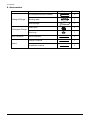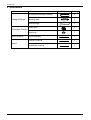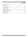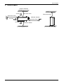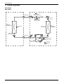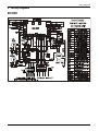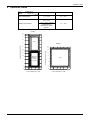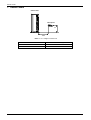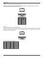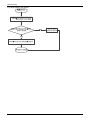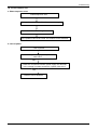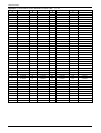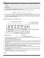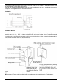
1
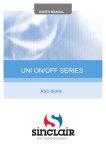
ON/OFF HEAT PUMP
Service manual
MUC-HF2
CL20647 a CL20648
English
Content
CONTENT
Part 1 General Information ..........................................................................1
Part 2 Indoor Units.......................................................................................5
Part 3 Outdoor Units .................................................................................. 51
Part 4 Installation ....................................................................................... 59
Part 5 Electrical Control System .............................................................. 85
※The specifications, designs, and information in this book are subject to change without notice for
product improvement.
2
General Information
Part 1
General Information
1. Model Lists..................................................................................................4
2. External Appearance ..................................................................................5
2.1 Indoor Units............................................................................................................... 5
2.2 Outdoor Units ............................................................................................................ 5
3. Features ..................................................................................................... 6
3
Model Lists
1. Model Lists
Universal Outdoor unit Model
Heat Pump
Compressor type
Compressor Brand
Matched indoor units
MUC-48 HF2 (UE20647)
SCROLL
SANYO
MUC-48 HF2 (UI20647)
MUC-60 HF2 (UE20648)
SCROLL
SANYO
MUC-48 HF2 (UI20648)
4
External Appearance
2. External Appearance
2.1 Indoor Unit
Duct
2.2 Outdoor Units
Double fan outdoor unit
5
Features
3. Features
4.1 High quality coils:
The coil is constructed of advanced inner grooved copper tube and aluminum fins.
4.2 Anti-rust, 500 hours salt spray test.
4.3 Low operation sound level: Well-known stable and quiet running fan motor.
4.4 Well-known compressor.
4.5 Compact design: Smaller dimension and larger stuffing capacity.
4.6 Universal outdoor unit design.
4.7 Optional air outlet grille: plastic type and wire type.
Wire type
Plastic type
4.8 Optional low temperature cooling module.
4.9 R410A environment friendly refrigerant.
6
Plastic type
Duct Type
Duct Type
1. Features .......................................................................................................7
2. Dimensions ................................................................................................ 11
3. Service Space ............................................................................................ 12
4. Wiring Diagrams ........................................................................................ 13
5. Static Pressure........................................................................................... 14
6. Electric Characteristics ............................................................................. 15
7. Sound Levels ............................................................................................. 16
8. Accessories ............................................................................................... 17
9. The Specification of Power ....................................................................... 18
10. Field Wiring .............................................................................................. 19
7
Features
1. Features
1.1 Installation accessories: (Optional)
Front Board, Canvas Air Passage, Filter, Panel, for easy installation
Front Board
Canvas Air Passage
Filter
Panel
1.2 Easy Installation: Two air inlet styles (Bottom side or Rear side)
Air inlet from rear is standard for all capacity; air inlet from bottom is optional.
The size of air inlet frame from rear and bottom is same, it’s very easy to move the cover from bottom to
rear side, or from rear to the bottom, in order to matching the installation condition.
Air intake from bottom (Optional)
Air intake from rear (Standard)
1.3 Easy maintenance
Clean the filter (Optional, standard product without filter)
It is easy to draw out the filter from the indoor unit for cleaning, even the filter is installed in rear side or
bottom side.
Replace the motor or centrifugal fan
Remove the ventilated panel firstly. Remove a half of blower housing and take out the motor with
centrifugal fan. Directly remove two bolts, and then replace the motor or centrifugal fan easily.
8
Features
Motor
Blower Housing
Ventilated Panel
1.4 Reserved remote on-off and central control ports
Reserved remote on-off ports and central control ports, can connect the cable of an on-off controller or a
central controller to realize remote on-off control function or group control function.
Remote on-off ports
Central control ports
1.5 Built-in drain pump (Optional):
750mm upmost
Built-in drain pump can lift the water to 750mm upmost. It’s convenient to install drainage piping under
most space condition.
9
Features
1.6 Built-in display board
The standard indoor unit can be controlled by wired controller.
There is a display board with a receiver in the E-box. Move out the display, and fix it in other place, even
in the distance of 10m. The unit will realized remoter control.
The wired controller and the display board can display the error code or production code when the chips
detect some failure.
Wired Controller (Standard)
Remote Controller (Optional)
Display
10
Dimensions
2. Dimensions
Capacity
(KBtu)
48~60
Outline
dimension(mm)
A
B
C
D
1200
300
865
800
E
Air outlet o
pening size
F
G
H
80
968
40
11
204
Air return
opening size
I
J
K
1094
288
45
Size of outline dimension
mounted plug
L
M
1240
500
Service Space
3. Service Space
Ensure enough space required for installation and maintenance.
There is enough space for installation and maintenance. The ceiling is horizontal, and its structure can
endure the weight of the indoor unit. The outlet and the inlet are not impeded, and the influence of external
air is the least. The air flow can reach throughout the room. The connecting pipe and drainpipe could be
extracted out easily. There is no direct radiation from heater.
12
Wiring Diagrams
4. Wiring Diagrams
MUC-48HF2
MUC-60HF2
13
Static Pressure
5. Static Pressure
45,000-48,000Btu/h
51,000-60,000Btu/h
Pa
120
48K
Pa
120
110
110
100
100
90
90
External static pressure (Pa)
70
60
50
Super high speed
High speed
Mid speed
Low speed
40
External static pressure (Pa)
80
80
Super high speed
70
60
50
40
High speed
Mid speed
Low speed
30
30
20
20
10
10
1000 1300 1600 1900 2200 2500 2800 3100 3400
Air volume(m3/h)
1000 1300 1600 1900 2200 2500 2800 3100
Air volume(m 3 /h)
14
Electric Characteristics
6. Electric Characteristics
Model
Indoor Unit
Power Supply
Hz
Voltage
Min
Max
MFA
MUC-48HF2
50
220-240V
198V
254V
16
MUC-60HF2
50
220-240V
198V
254V
16
Note:
MFA: Max. Fuse Amps. (A)
15
Sound Levels
7. Sound Levels
Concealed Duct Type
Discharge
Suction
Duct
Duct
1.4m
Microphone
Noise level dB(A)
Model
H
M
L
MUC-48HF2
49
45
40
MUC-60HF2
49
45
40
16
Accessories
8. Accessories
Name
Tubing & Fittings
Shape
Quantity
Soundproof/insulation sheath
2
Binding tape
1
Seal sponge
1
Drain joint
1
Seal ring
1
Wire controller
1
Owner's manual
1
Installation manual
1
Drainpipe Fittings
Wire controller
others
17
The Specification of Power
9. The Specification of Power
MUC-48HF2
MUC-60HF2
1-phase
Model
Phase
INDOOR UNIT POWER
Frequency and Voltage
2
POWER WIRING (mm )
3×1.0
Circuit Breaker/ Fuse (A)
20/16
Phase
OUTDOOR UNIT POWER
220-240V, 50Hz
3-phase
Frequency and Voltage
2
380-415V, 50Hz
POWER WIRING (mm )
5×2.5
Circuit Breaker/ Fuse (A)
Indoor/Outdoor Connecting Wiring
2
(Weak Electric Signal) (mm )
Indoor/Outdoor Connecting Wiring
2
(Strong Electric Signal) (mm )
25/20
18
3×0.2
Accessories
8. Accessories
Name
Tubing & Fittings
Shape
Quantity
Soundproof/insulation sheath
2
Binding tape
1
Seal sponge
1
Drain joint
1
Seal ring
1
Wire controller
1
Owner's manual
1
Installation manual
1
Drainpipe Fittings
Wire controller
others
19
Outdoor Units
Part 3
Outdoor Units
1. Dimensions ...............................................................................................21
2. Service Space ...........................................................................................22
3. Piping Diagrams .......................................................................................23
4. Wiring Diagrams .......................................................................................24
5. Electric Characteristics ............................................................................25
6. Operation Limits ....................................................................................... 26
7. Sound Levels ............................................................................................ 27
20
Dimensions
1. Dimensions
Unit:mm
Model
MUC-48HF2
MUC-60HF2
A
B
C
D
E
F
H
938
634
404
448
370
392
1369
21
Service Space
2. Service Space
(Wall or obstacle)
Air inlet
More than 30cm
Air inlet
More than 30cm
Maintain channel
More than 60cm
Air outlet
More than 200cm
22
More than 60cm
Piping Diagrams
3. Piping Diagrams
MUC-48HF2
MUC-60HF2
INDOOR
OUTDOOR
CHECK VALVE
(Heating Model only)
LIQUID SIDE
2-WAY VALVE
T3 Condenser
temp. sensor
CAPILIARY TUBE
HEAT
EXCHANGE
(EVAPORATOR)
HEAT
EXCHANGE
(CONDENSER)
T4 Ambient
temp. sensor
T1 Room temp.
sensor
T2 Evaporator
temp. sensor
GAS SIDE
4-WAY VALVE
3-WAY VALVE
Accumulator
Compressor
High pressure switch
T5 Discharge temp. sensor
Low pressure
switch
COOLING
HEATING
23
Wiring Diagrams
4. Wiring Diagrams
MUC-48HF2
MUC-60HF2
24
Electric Characteristics
5. Electric Characteristics
Model
Outdoor Unit
Hz
Voltage
Min.
Max.
MUC-48HF2
50
380~415V
342V
435V
MUC-60HF2
50
380~415V
342V
435V
25
Operation Limits
6. Operation Limits
Temperature
Mode
Cooling operation
Heating operation
17℃~32℃
0℃~30℃
Room temperature
18℃~43℃
(-7℃~43℃:For the
models with low
temperature cooling
system)
Outdoor temperature
-7℃~24℃
Cooling
45
43
40
35
STD
Heating
25
25
24
20
18
20
Outdoor temperature(℃ DB)
Outdoor temperature(℃ DB)
30
15
10
With Low
Ambient
Cooling
System
5
0
-5
-7
15
10
STD
5
0
-5
-7
-10
-10
10
15 17 20
25
30 32 35
0
Indoor temperature(℃ WB)
5
10
15
20
Indoor temperature(℃ WB)
26
25
30
Sound Levels
7. Sound Levels
Outdoor Unit
Microphone
H
1.0m
Note: H= 0.5 × height of outdoor unit
Model
Noise level dB(A)
MUC-48HF2
62
MUC-60HF2
63
27
Electrical Control
Part 4
Electrical Control System
1. Electrical Control Function .................................................................. 29
2. Troubleshooting ...................................................................................36
3. Controller ..............................................................................................50
28
Electrical Control Function
1. Electrical Control Function
1.1 Definition
T1: Indoor room temperature
T2: Coil temperature of evaporator
T3: Coil temperature of condenser
T4: Outdoor ambient temperature
T5: Compressor discharge temperature
1.2 Main Protection
1.2.1 Time delay at restart for compressor.
1.2.2 Sensor protection at open circuit and breaking disconnection.
1.2.3 Phase check function
If the phase sequence is detected wrong or lack of 1 or 2 phase, the unit won’t start and there is error code
displayed on outdoor PCB.
1.2.4 Over-current protection
When compressor is running, if the current is over twice of the rated for 3 seconds, the compressor will stop
and an error code will be displayed on the outdoor PCB. If the current becomes normal, the indoor sends
signal to the outdoor, the outdoor will display normally.
1.2.5 Fan Speed is out of control
When Indoor fan speed keeps too low (less than 300RPM) for 50s, the unit will stop and the LED will display
the failure.
29
Electrical Control Function
1.3 Operation Modes and Functions
1.3.1 Fan mode
(1) Outdoor fan and compressor stop.
(2) Temperature setting function is disabled, and no setting temperature is displayed.
(3) Indoor fan can be set to high/(med)/low/auto.
(4) The louver operates same as in cooling mode.
(5) Auto fan:
T1
27
High
26
Medium
24
Low
1.3.2 Cooling Mode
1.3.2.1 Compressor running rules
Once the compressor starts up, it will follow the below rules:
When indoor room temp.T1 is lower than Ts, the compressor and outdoor fan will shut off. When T1 is higher
than Ts+1, the compressor and outdoor fan will start up.
T1
Ts+1
On
Ts
Off
1.3.2.2 Outdoor fan running rules
For double-fan outdoor units:
Fan(above): The outdoor fan runs all the time.
Fan(below):
T3
33
On
30
Off
30
Electrical Control Function
1.3.2.3 Indoor fan running rules
In cooling mode, indoor fan runs all the time and the speed can be selected as high, medium, low and auto.
The auto fan:
T1-Ts
4
High
3
Medium
1
Low
1.3.2.4 Low evaporator coil temperature T2 protection
For Duct:
T2
On
TE6
TE5
Off
When the evaporator coil temp.T2 keeps lower than TE5 for Time0, the compressor and outdoor fan will shut
off. When T2 is higher than TE6, the compressor and outdoor fan will restart up.
1.3.2.5 Condenser high temperature T3 protection
T3
Off
TE12
TE13
On
When T3>TE12 for Time1, the compressor will shut off. When T3≤TE13,the compressor will restart.
31
Electrical Control Function
1.3.3 Heating Mode
1.3.3.1 Compressor running rules:
For Duct & super-slim cassette type: Once the compressor starts up, it keeps running 7 minutes,
When indoor room temp.T1 is higher than Tgap0, the compressor and outdoor fan will shut off. When T1 is
lower than Tgap0-1, the compressor and outdoor fan will start up.
T1-TS
Off
Tgap0
Tgap0-1
On
1.3.3.2 Outdoor fan running rules:
Fan(below): The outdoor fan runs all the time.
Fan(above):
T4
18
Off
16
On
1.3.3.3 Indoor fan running rules:
When the compressor is on, the indoor fan can be set to high/med/low/auto. And the anti-cold wind function
has the priority.
Auto fan action:
T1-Ts
Low
3
2
1
Medium
High
32
Electrical Control Function
1.3.3.4 Defrosting mode:
Condition of defrosting:
AC will enter defrosting mode if any of the following items is satisfied.
A: T3< TE19 and the compressor keeps running over 45 minutes. Meanwhile T3<TE17 for 3minutes.
B: After the last defrosting, the time that the outdoor fan is off but the compressor is on in high T2 protection
cumulates up to 90 minutes.
Condition of ending defrosting:
If any one of the following items is satisfied, the defrosting will terminate and the machine will turn to normal
heating mode.
A: T3 rises to be higher than TE18.
B: The machine has run for 10 minutes in defrosting.
C: Turn to other modes or off.
Defrosting action:
Setting defrosting time
45S
45S
Compressor
4 way valve
40S
40S
Outdoor fan
Indoor fan
10S
1.3.3.5 High evaporator coil temp.T2 protection:
Compressor off Outdoor fan off
TE9
Compressor on Outdoor fan off
TE8
TE10
Compressor on Outdoor fan on
TE11
33
Electrical Control Function
1.3.4 Auto-mode
This mode can be chosen with remote controller and the setting temperature can be changed between
17~30℃.
In auto mode, the machine will choose cooling, heating or fan-only mode according to ∆T (∆T =T1-Ts).
∆T=T1-Ts
Running mode
∆T>2℃
Cooling
-1≤∆T≤2℃
Fan-only
∆T<-1℃
Heating
Indoor fan will run at auto fan of the relevant mode.
The louver operates same as in relevant mode.
If the machine switches mode between heating and cooling, the compressor will keep stopping for 15
minutes and then choose mode according to T1-Ts.
If the setting temperature is modified, the machine will choose running function again.
1.3.5 Drying mode
1.3.5.1 The indoor fan will keep running at low speed.
1.3.5.2 All protections are active and the same as that in cooling mode.
1.3.5.3 The louver operates the same as in cooling mode.
1.3.6 Timer function
1.3.6.1 Timing range is 24 hours.
1.3.6.2 Timer on. The machine will turn on automatically when reaching the setting time.
1.3.6.3 Timer off. The machine will turn off automatically when reaching the setting time.
1.3.6.4 Timer on/off. The machine will turn on automatically when reaching the setting “on” time, and then
turn off automatically when reaching the setting “off” time.
1.3.6.5 Timer off/on. The machine will turn off automatically when reaching the setting “off” time, and then
turn on automatically when reaching the setting “on” time.
1.3.6.6 The timer function will not change the AC current operation mode. Suppose AC is off now, it will not
start up firstly after setting the “timer off” function. And when reaching the setting time, the timer LED will be
off and the AC running mode has not been changed.
1.3.6.7 The setting time is relative time.
1.3.7 Economy function
1.3.7.1 It is valid in cooling, heating and auto mode.
1.3.7.2. Turning off, changing mode or setting fan speed will cancel economy function.
1.3.7.3 Operation process in sleep mode is as follow:
After pressing ECONOMIC or SLEEP button on the controller, the machine will go into economy mode.
34
Electrical Control Function
When cooling, the setting temperature rises 1℃(be lower than 30℃) every hour, 2 hours later the setting
temperature stops rising.
For heat pump models, when they are in heating, the setting temperature reduces 1℃(be higher than 17℃)
every hour, 2 hours later the setting temperature stops reducing.
1.3.7.4 In this mode, the fan speed is forced into AUTO mode.
1.3.8 Auto-Restart function
The indoor unit is equipped with auto-restart function, which is carried out through an auto-restart module. In
case of a sudden power failure, the module memorizes the setting conditions before the power failure. The
unit will resume the previous operation setting (not including Swing function) automatically after 3 minutes
when power returns.
1.3.9 Drain pump control
1.3.9.1 Water level check
The water lever will be checked every 5 seconds, if the feedback signal is abnormal, it will be considered as
drain water full by the control system.
1.3.9.2 Drain pump control
If there is no water full error, the drain pump will be on when the unit is in cooling mode (including
auto-cooling and forced cooling) and dry mode. It will be off when the unit is in heating mode, fan only mode
or off state (if the pump is on before the unit is off, it will delay 3 minutes to be off).
If there is a water full error, the drain pump will be on when the error occurs. Afterwards:
If the error disappears in 3 minutes, the drain pump will work as normal state. (if it is necessary to turn off the
pump, it will be off in 1 minute delay.)
If the error is still there in 3 minutes, the drain pump will be off as well as the AC unit. The error can be
cleared only when the power of the unit is cut off.
35
Troubleshooting
2. Troubleshooting
2.1 Display board
2.1.1 Icon explanation on indoor display board
PRE-DEF indicator(cooling and heating type)
or fan only indicator(cooling only type)
Alarm indicator
Timer indicator
Infrared signal receiver
Operation lamp
Display digital tube
Temporary button
MANUAL OPERATION TIMER DEF./FAN ALARM
36
Troubleshooting
2.2. Self-diagnosis
Indoor unit’s LED indication
Display
NO.
Malfunction
Running
lamp
Timer
lamp
Defrosting
lamp
Alarm
lamp
(digital tube)
1
Communication malfunction between indoor
and outdoor units
☆
X
☆
X
E1
2
Open or short circuit of T1 temperature
sensor
X
☆
X
X
E2
3
Open or short circuit of T2 temperature
sensor
☆
X
X
X
E3
4
Outdoor unit malfunction
☆
☆
☆
☆
E6
5
Indoor EEPROM malfunction
☆
☆
X
X
E7
6
Full-water malfunction
X
X
X
☆
E8
7
Indoor fan speed is out of control
X
☆
X
☆
Eb
7
Protection of low pressure
☆
☆
☆
X
Ed
O (on)
X(off) ☆(flash at 5Hz)
LEDs’ for the indication of outdoor trouble
Type
Contents
LED2(Green)
LED3(Yellow)
LED4(Red)
Normal
Normal running
O
X
X
Normal
Normal standby
X
O
X
Trouble
Phase sequence error
X
☆
X
Trouble
Lack of phase
X
X
☆
Trouble
Open-circuit and short-circuit trouble of T3
X
X
O
Trouble
☆
X
X
O
X
O
Trouble
Open-circuit and short-circuit trouble of T4
Temperature protection of compressor
discharge
Protection of high pressure
☆
☆
X
Trouble
Protection of low pressure
☆
X
☆
Trouble
Trouble
Overload of current
X
☆
O
Trouble
High temperature protection of condenser
☆
☆
O
Trouble
Fan selection error
☆
☆
☆
O(light)
X(off)
☆(flash at 1Hz)
Note:
1. T3: Outdoor condenser temperature sensor
2. T4: Outdoor ambient temperature sensor
37
Troubleshooting
2.3. Solving steps for typical malfunction
(1) For indoor unit
a. Communication malfunction between indoor and outdoor units (E1)
38
Troubleshooting
b. Open or short circuit of temperature sensor(E2,E3, E4)
Check the connections
between temperature
sensor and PCB. Are
the connections good?
No
Correct the connections.
Yes
Check the resistance value
of the sensor via Appendix 1
Is it normal?
Yes
Replace indoor or outdoor PCB.
No
Replace the sensor
39
Troubleshooting
c. Outdoor unit malfunction (E6)
Outdoor unit malfunction
Whether the outdoor
main board has error
display
Yes
Refer to corresponding solving steps
No
Check whether the power is on
No
Connect the wiring well or
replace the communication wire
No
Whether the outdoor
unit is power on
Yes
Check whether the
communication wire
between the indoor and
outdoor unit is
connected correctly
Yes
Replace outdoor main
board
check if the errors
happen again?
No
Yes
Replace the indoor PCB
Trouble is solved
40
Troubleshooting
d. Indoor EEPROM malfunction (E7)
Shut off the power supply and
turn it on 5 seconds later. Is it
still displaying the error code?
Yes
If the EEPROM chip
is welded on PCB,
replace the PCB
directly. Otherwise,
check whether the
EEPROM chip
plugged in PCB well?
No
Insert the EEPROM well
Yes
Replace the indoor PCB.
e. Full-water malfunction (E8)
If the water-level switch
is inserted well?
No
Insert the water-level switch well
Yes
Replace the water-level switch
Yes
If the water-level switch
is broken?
No
If the water pump is
normal?
No
Replace the water pump
Yes
Check PCB board or replace the indoor main PCB
41
Troubleshooting
f. Indoor fan speed has been out of control (Eb)
42
Troubleshooting
Index 1:
1.Indoor DC fan motor(control chip is inside fan motor)
Measure the resistance value of each winding by using the tester. If any resistance value is zero, the fan
motor must have problems and need to be replaced.
NO.
1
2
3
4
5
6
Color
Red
--Black
White
Yellow
Blue
Index2:
1. DC fan motor(control chip is inside fan motor)
Power on and when the unit is in standby, measure the voltage of pin1-pin3, pin4-pin3 in fan motor
connector. If the value of the voltage is not in the range showing in below table, the PCB must have
problems and need to be replaced.
DC motor voltage input and output
NO.
Color
Signal
Voltage
1
Red
Vs/Vm
140~380V
2
---
---
---
3
Black
GND
0V
4
White
Vcc
13.5~16.5V
5
Yellow
Vsp
0~6.5V
6
Blue
FG
15V
43
Troubleshooting
For the super-slim cassette with up-down panel
a. Communication error between indoor unit and up-down panel
b. Up-down panel is defective
44
Troubleshooting
c Up-down panel is not closed
45
Troubleshooting
(2) For the outdoor unit
a. Phase sequence error:
Phase sequence error
Change the order of two of the wires to power supply.
Switch on the unit again.
If the problem cannot be solved, the outdoor PCB is defective
b. Lack of phase
Lack of phase
Check the power supply, is it 3 phase,
380-415V?
Yes
Check the connection between power supply and terminal,
is the voltage in outdoor terminal is 3 phase, 380-415V?
Yes
Outdoor PCB is defective
46
Troubleshooting
c. Overload of current
Overload of current
Check the current, normally
Is the current in rated range?
No
Yes
The outdoor PCB is defective
Possible reason
1. Outdoor fan is defective
2. The compressor is defective
3. Refrigerant is over charged
4. Air enter the refrigerant system
d. Protection of pressure or temp.
Protection of pressure or temp.
Yes
Is it K1 or K2 open ?
Is temp. protective switch K1 close
Yes
Possible reason
1. The wires is loose to K1
2. Air or other gas in the refrigerant.
3. Heat exchanger is dirty
4. Outdoor fan or fan blade is
defective
5. Outdoor unit is in bad ventilation
6. Refrigerant is leakage
7. K1 switch is defective
Is pressure protective switch K2 close
Yes
Possible reason
1. The wires is loose to K2
2. Air or other gas in the refrigerant.
3. Heat exchanger is dirty
4. Outdoor motor or fan blade is
defective
5. Outdoor unit is in bad ventilation
6. Refrigerant is too much
7. K2 switch is defective
47
Troubleshooting
e. High temperature protection of condenser
High temperature protection of condenser
Check the resistance of the temp. sensor
according to Appendix 1, is it normal?
No
Yes
Replace the sensor
Possible reason
1. Air or other gas in the refrigerant.
2. Heat exchanger is dirty
3. Outdoor fan or fan blade is
defective
4. Outdoor unit is bad ventilation
5. Refrigerant is leakage
48
Troubleshooting
Appendix 1 Temperature Sensor Resistance Value Table (℃--K)
℃
20
K Ohm
12.6431
℃
60
K Ohm
2.35774
℃
100
K Ohm
0.62973
-19
115.266
108.146
21
12.0561
61
2.27249
101
0.61148
-18
101.517
22
11.5000
62
2.19073
102
0.59386
-17
96.3423
23
10.9731
63
2.11241
103
0.57683
-16
89.5865
24
10.4736
64
2.03732
104
0.56038
-15
84.2190
25
10.000
65
1.96532
105
0.54448
-14
79.3110
26
9.55074
66
1.89627
106
0.52912
-13
74.5360
27
9.12445
67
1.83003
107
0.51426
-12
70.1698
28
8.71983
68
1.76647
108
0.49989
-11
66.0898
29
8.33566
69
1.70547
109
0.48600
℃
-20
K Ohm
-10
62.2756
30
7.97078
70
1.64691
110
0.47256
-9
58.7079
31
7.62411
71
1.59068
111
0.45957
-8
56.3694
32
7.29464
72
1.53668
112
0.44699
-7
52.2438
33
6.98142
73
1.48481
113
0.43482
-6
49.3161
34
6.68355
74
1.43498
114
0.42304
-5
46.5725
35
6.40021
75
1.38703
115
0.41164
-4
44.0000
36
6.13059
76
1.34105
116
0.40060
-3
41.5878
37
5.87359
77
1.29078
117
0.38991
-2
39.8239
38
5.62961
78
1.25423
118
0.37956
-1
37.1988
39
5.39689
79
1.21330
119
0.36954
0
35.2024
40
5.17519
80
1.17393
120
0.35982
1
33.3269
41
4.96392
81
1.13604
121
0.35042
2
31.5635
42
4.76253
82
1.09958
122
0.3413
3
29.9058
43
4.57050
83
1.06448
123
0.33246
4
28.3459
44
4.38736
84
1.03069
124
0.32390
5
26.8778
45
4.21263
85
0.99815
125
0.31559
6
25.4954
46
4.04589
86
0.96681
126
0.30754
7
24.1932
47
3.88673
87
0.93662
127
0.29974
8
22.5662
48
3.73476
88
0.90753
128
0.29216
9
21.8094
49
3.58962
89
0.87950
129
0.28482
10
20.7184
50
3.45097
90
0.85248
130
0.27770
11
19.6891
51
3.31847
91
0.82643
131
0.27078
12
18.7177
52
3.19183
92
0.80132
132
0.26408
13
17.8005
53
3.07075
93
0.77709
133
0.25757
14
16.9341
54
2.95896
94
0.75373
134
0.25125
15
16.1156
55
2.84421
95
0.73119
135
0.24512
16
15.3418
56
2.73823
96
0.70944
136
0.23916
17
14.6181
57
2.63682
97
0.68844
137
0.23338
18
13.9180
58
2.53973
98
0.66818
138
0.22776
19
13.2631
59
2.44677
99
0.64862
139
0.22231
49
Controller
3. Controller
3.1 Wireless Remote Controller
3.1.1 RG51Q1/BGE
The R51Q1/BGE wireless remote controller is standard for Four-way cassette type and the Ceiling& floor
type.
General Function for wireless remote controller:
Model
RG51Q1/BGE
Rated voltage
3.0V(2pieces of LR03 7# batteries)
Min voltage for sending signal of CPU
2.4V
Effective receiving distance
8m~11m
Operation condition
-5~60℃
50
Controller
Buttons and functions
1. Adjust
: Decrease the set temp. Keeping pressing will decrease the temp with 1℃ per 0.5s.
2. Adjust
: Increase the set temp. Keeping pressing will increase the temp with 1℃ per 0.5s.
3. MODE: Once pressing, running mode will be selected in the following sequence:
AUTO
COOL
DRY
HEAT
FAN
NOTE: No heating mode for cool only type unit.
4. VERT SWING: Used to stop or start horizontal louver movement or set the desired up/down air flow
direction. The louver changes 6 degree in angle for each press. If keep pushing more than 2 seconds, the
louver will swing up and down automatically.
5. HORIZ SWING: Used to stop or start vertical louver movement.
6. AIR DIRECTION: Used to set the desired up/down air flow direction. The louver changes 6 degree in
angle for each press.
7. ON/OFF: For turning on or turning off the air conditioner.
8. FAN SPEED: Fan speed will be selected in following sequence once pressing this button:
AUTO
LOW
MED
HIGH
9. TIME ON: For time ON setting. Once pressing this button, the time will increase by 0.5 hour. When the set
time exceeds 10 hours, pressing the button will increase the time by 1 hour. Adjusting the figure to 0.00 will
cancel time ON setting.
10. ECO: Activate or turn off economic operation mode. It is suggested to turn on this function when sleeping.
(Only available when remote controller is used with corresponding unit.)
11. TIME OFF: For time OFF setting. Once pressing this button, the time will increase by 0.5 hour. When the
set time exceeds 10 hours, pressing the button will increase the time by 1 hour.
Adjust the figure to 0.00 will cancel time ON setting.
12. C/H (inner located): Press this button with a needle of 1mm to shift the mode between Cooling only and
Cooling & Heating according to the feature of the machine.
13.RESET (inner located): Press this button with a needle of 1mm to cancel the current setting and reset
remote controller.
51
Controller
3.1.2 RG51C/E
Remote Controller Specifications
Model
RG51C/E
Rated Voltage
3.0V
Lowest Voltage of CPU Emitting Signal
2.0V
Reaching Distance
8m (when using 3.0 voltage, it can get 11m)
Environment Temperature Range
-5℃~60℃
Introduction of Function Buttons on the Remote Controller
SET TEM PERATURE( C)
FAN
HIGH
MED
LOW
AU TO
COOL
DR Y
HE AT
ADJUST
Adju st
1
2
7
3
SWING
SWING
4
ECO
RESET LOC K
8
Fan speed se tt ing
9
TI MER ON
10
Econom ic ope rat ion
11
TIME R OFF
12
L ock
13
Re s et
TIMER ON
TI MER OFF
5
AI R
DIRECTI ON
1. Adjust
ON/ OFF
ON/O FF FAN SPEED
MODE
Mod e sett in g
Adj ust
: Decrease the set temp. Keeping pressing will decrease the temp with 1℃ per 0.5s.
2. Adjust
: Increase the set temp. Keeping pressing will increase the temp with 1℃ per 0.5s.
3. MODE: Once pressing, running mode will be selected in the following sequence:
AUTO
COOL
DRY
HEAT
FAN
NOTE: No heating mode for cool only type unit.
4. VERT SWING: Used to stop or start horizontal louver movement. The louver will swing up and down
automatically if push this button.
AIR DIRECTION: Used to set the desired up/down air flow direction. The louver changes 6 degree in
angle for each press.
5. HORIZ SWING: Used to stop or start vertical louver movement.
6. FAN SPEED+ MODE: Press the Mode and Fan speed button simultaneously for 2 seconds. The remote
52
Controller
controls into faceplate setting state and the LCD shows F2.Press the TEMPUP( ) to control the faceplate
up and press the TEMP DOWN( ) to control the faceplate down. Press any button to exit the faceplate
setting state, then the LCD back to the normal display.
7. ON/OFF: For turning on or turning off the air conditioner.
8. FAN SPEED: Fan speed will be selected in following sequence once pressing this button:
AUTO
LOW
MED
HIGH
9. TIME ON: For time ON setting. Once pressing this button, the time will increase by 0.5 hour. When the set
time exceeds 10 hours, pressing the button will increase the time by 1 hour. Adjusting the figure to 0.00 will
cancel time ON setting.
10. ECO: Select this function during the sleeping time. It can maintain the most comfortable temperature
and save energy. This function is available on COOL, HEAT or AUTO mode only .
NOTE: While the unit is running under Energy-saving mode, it would be cancelled if press MODE, FAN
SPEED or ON/OFF button.
11. TIME OFF: For time OFF setting. Once pressing this button, the time will increase by 0.5 hour. When the
set time exceeds 10 hours, pressing the button will increase the time by 1 hour.
Adjust the figure to 0.00 will cancel time ON setting.
12. LOCK (inner located): Push this button to lock in all the current settings, and the remote controller will
not accept any operation except that of the LOCK. Use the LOCK mode when you want to prevent settings
from being changed accidentally. Press the LOCK button again to cancel the LOCK function. A lock symbol
will appear on the remote controller display when the lock function is activated.
13.RESET (inner located): Once the recessed RESET button is pressed, all of the current settings will be
cancelled and the controller will return to the initial settings..
53
Controller
3.2 Wired Remote Controller
3.2.1 KJR-12B
Name and functions of buttons on the wire controller
1.
Mode button: When press this button, the operation mode change as the following sequence:
AUTO
2.
3.
4.
5.
6.
7.
COOL
DRY
HEAT
FAN
Remark: For the cooling only model, the heating mode is skipped.
Timer on button: Press this button, timer on function is active. Then every press, the time increase 0.5h,
after 10h, 1h increasement after each press. If cancel this Function, just set it to "0.0"
Timer off button: Press this button, timer off function is active. Then every press, the time increase 0.5h,
after 10h, 1h increasement after each press. If cancel this function, just set it to "0.0" .
Follow me button: When under cool, heat and auto mode, press this button, follow me function is active.
Press again, this function is ineffective.
Electrical heater button: If press this button in heat mode, electrical heater function become ineffective.
Reset button (hidden): Use a 1mm stick to press in the little hole , then the current setting is canceled .
The wire controllers enter into original state.
ON/OFF button: When in off state, press this button, the indicator is on, the wire controller enter into on
state, and send setting information to indoor PCB. When in on state, press this button, the indicator is
off, and send instruction. If timer on or timer off has been set, it cancel this setting then send instruction
to stop the machine.
54
Controller
8.
Adjust button: Set indoor temperature up. If press and hold on, it will increase at 1degree per 0.5
second.
9. Adjust button: Set indoor temperature down. if press and hold on, it will decrease at 1degree per 0.5
Second.
10. Swing button: First press, start swing function; second press, stop swing. (Match to some model with
swing function).
11. Economy operation button: press this button, the indoor unit operates in economy mode, press again,
exit this mode (it may be ineffective for some models)
12. Fan speed button: press this button consecutively; the fan speed will circle as follow:
13. Lock button (hidden): When you push the LOCK button, all current settings are locked in and the wire
controller does not accept any operation except that of the LOCK button. Use the lock mode when you
want to prevent setting from being changed accidentally or play fully. Push the LOCK button again when
you want to cancel the LOCK mode.
Name and function of LCD on the wire controller
1.
2.
3.
4
5.
6.
7.
Operation mode indication: When press” MODE” button, the following mode can be selected in circle.
Auto Cool Dry Heat Fan only Auto.
Auto→ Cool→ Dry →Heat→ Fan only →Auto
For cooling only model, heat mode is skipped.
Timer: When adjust setting on time or only on time is set, the “ON” is lighted. When adjust setting off
time or only off time is set, the” OFF" is lighted. If on and off timer are both set, the “ON” and “OFF” are
both lighted.
Follow me function: There is a temperature sensor inside the wire controller, after setting temperature, it
will compare the two temperatures, and the space of wire controller will be the same as setting
temperature. It is available under cooling, heating, auto mode.
ON/OFF indication: When it is on, the icon display, otherwise it is extinguished.
Fan speed indication: There are four fan modes: low, middle, high, auto. For some models, no middle
fan then the middle fan is seen as high speed.
Lock: When the "LOCK" button is pressed, the icon appears and other buttons is unable, press again,
the icon disappears.
Temperature display zone: Generally it displays setting temperature; it can be adjusted by press
temperature button▲and▼ .But in fan mode, no display here.
Remark:
55
Controller
The wired controller will reset to factory setting with auto mode, auto fan and 24℃ setting temperature when
the air conditioner restarts after power failure.
And this may cause inconsistent displays on the wired controller and on the air conditioner. You need to
readjust the running status through the wired controller.
Installation
Installation Notice:
When the air conditioner needs the constant frequency wire controller, be sure adding a wire joint with 5
terminal named A, B, C, D, E in indoor unit, and fixing an infrared emitter whose anode and cathode
connecting with A and B near the receiver in the indoor unit switch board, then connecting the terminal +5v,
GND, Run in the switch board to C,D,E respectively.
NOTE
●The connecting wire should be a little longer as to take away the switch board easily for maintenance.
●The connecting wire should be a little longer as to take away the controller easily for maintenance.
56
SOLICITE INFORMACIÓN ADICIONAL:
Teléfono: 93 446 27 80 - Fax: 93 456 90 32
eMail: [email protected]
ASISTENCIA TÉCNICA:
Teléfono: 93 652 53 57 - Fax: 93 635 45 08
57