1
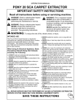
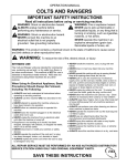
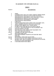
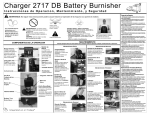
Mobile Lighting Towers
HD-S Operation &
Maintenance Manual
+44 (0)843 855 0068
www.heimdalluk.co.uk
Contents
Make a note of the machine Vehicle Identification
Number (VIN) in this box for future reference and
when ordering replacement parts.
1. Introduction
5
2. General Safety
6
It is the responsibility of the operator to read
and understand the contents of this manual
before operating the unit for the first time.
3. Know Your Unit
Technical Data
Towing Legally
Vehicle Identification Number (VIN)
Other Legal Requirements
Road Lighting
Safety Decals
8
10
12
12
12
14
15
The Operators Manual must accompany
the unit at all times. If the unit is resold the
Operators Manual must be given with the
unit to the new owners.
4. Licence / Towing the Unit
Attaching the Unit to the Towing Vehicle
Manoeuvring the Unit
Reversing the Unit
24
28
33
34
5. Controls
Support Legs Control Panel
Mast Raise / Lower control
Main Isolator
Engine / Generator Information Panel
Status Indicators
Fault Icons
Smart Stability System
Manual Hydraulic Override
36
38
39
39
40
41
42
44
49
VIN
2
The world’s most advanced lighting towers
CONTENTS
Please read and follow
all instructions before
operating the unit
Mobile Lighting Towers
Operation & Maintenance Manual
3
6. Setting Up
Positioning
Arriving on Site
Deployment
Starting the Engine
Stopping the Engine
Deploying the Support Legs
Stowing the Support Legs
Adjusting the Lamps
Rotating the Mast
Raise & Lower the Mast
Lifting Procedure
50
50
50
50
51
52
52
53
53
54
55
56
7. Maintenance
Maintenance Schedule
Changing or Removing a Wheel
Brake Maintenance
Changing Engine Oil
58
59
60
61
62
8. Warranty
64
9. Fault Finding
66
www.heimdalluk.co.uk
Description
The Heimdall range of mobile lighting towers are road towable
units suitable for the illumination of public events, street works
and emergency situations.
To avoid personal injury, before using this
equipment carefully read these instructions
and ensure you understand them. If there is
anything you do not understand, DO NOT use this
equipment, and contact your supplier for advice.
These self contained units can be rapidly installed to provide
constant illumination over a large area.
Ensure everyone responsible is fully conversant
with the procedure for attaching the towing vehicle,
towing, loading, setting up and operating the unit.
Certain information in this manual is governed by
law and is subject to change without prior notice.
This is their intended use.
Electrical supply is from a built in generator. The units cannot be
used for the support of any other equipment without the prior
design consent of the manufacturer.
Great care has been taken to ensure that the
information is correct at the time of publication.
However, it is the users sole responsibility
to ensure that they fully comply with all
legal requirements.
Guidance
The information and instructions included in this manual are
provided to help you get the best possible service from your
lighting tower.
To ensure that the unit is used safely and responsibly, we strongly
recommend that this manual is read by all users prior to its operation,
and that the recommendations are followed at all times. Heimdall
operates a policy of continuous improvement and reserve the
right to change specifications without notice.
4
The world’s most advanced lighting towers
5
www.heimdalluk.co.uk
1. INTRODUCTION
1. Introduction
Thank you for purchasing
this Heimdall mobile
lighting tower
Safety
Safety is everyone’s responsibility
Before using this equipment and to avoid personal injury, carefully
read and understand these instructions. If there is anything you do
not understand, DO NOT use this equipment, contact the supplier
for advice.
Risk Assessment
Make sure you are aware of all the safety requirements and that this
equipment is suitable for the location.
It is the user’s responsibility to carry out a full risk assessment
before siting the unit, to establish a safe zone including (but not
limited to):
Ground hazards
Site preparation, suitable smooth level ground
capable of bearing the mass of the unit in all
weather conditions.
When manoeuvring the unit into position, if working on a public
road or in a public accessible space use the high intensity warning
beacons fitted to the towing vehicle or its hazard warning lamps to
raise awareness of its movement. If visibility is limited use a
banksman or other assistance to guide you.
Site hazards
When raising or lowering the unit, the area must be cordoned off
to create a safe zone, isolating the unit from the general public and
bystanders.
Overhead hazards Proximity to power supply and communication
cables, lighting systems and other services.
This equipment must not be moved, set up, used or dismantled by
persons who are under the influence of alcohol or drugs. Do not use
this equipment if you are tired or unwell.
The equipment must not be operated, moved or used by any person
not deemed competent to do so.
You MUST perform a risk assessment before siting this equipment to
ensure your safety and the safety of others. Wear suitable personal
protective equipment whenever making adjustments to the unit.
Do not wear loose jewellery or clothing that may get in the way or
become trapped in the mechanism.
Proximity to underground services etc.
If permission is required, obtain it before use.
Proximity to other buildings trenches and
equipment, clearances for exhaust outlet and
ventilation where required.
Preparation for Towing
Before towing the unit,
•
Switch the generator OFF.
•
Make sure the Mast is fully retracted and locked in the
transport position.
•
Make sure the support legs are fully raised and locked
into position with their pins.
•
Close and secure all protective covers.
•
The unit must not be used as a payload trailer, additional items
carried in the trailer may cause the unit to be overweight.
Work Area Preparation
Carefully inspect the unit before towing or before use. If there is any
doubt about its condition, DO NOT CONTINUE.
This equipment may only be used on smooth level ground, which is
able to bear its weight and its load.
Survey the ground area where the unit is to be used, clear
it of obstructions, anything that may puncture the tyres
and similar items.
Once the unit is in the work area, use barriers, signs and tape to
create a safe zone. Keep bystanders and unauthorised persons
away when setting the unit up.
6
The world’s most advanced lighting towers
7
www.heimdalluk.co.uk
2 . GENERAL SAFETY
2. General Safety
Item
Description
1
50mm Standard Ball Coupler with Inertia Overrun Brake Actuator
2
Parking Brake
3
Support Leg
4
Support Leg Cylinder
5
Front Side Marker Lamps / Reflectors *
6
Ventilation Grille
7
Exhaust Outlet
8
Telescopic Mast
9
Lighting Head
10
Lift Cylinder
11
Jockey Wheel
12
Side Marker Reflectors *
13
External Power Connections
14
Control Panel Access Cover
15
Crane Lifting Point
16
Engine/Generator Access Cover
17
Rear Road Lights *
18
Fork Lifting Point
3. KNOW YOUR UNIT
3. Know Your Unit
12
13
14
15
6
18
9
8
10
7
Note!
It is an offence to tow the unit if the items
marked * are not fitted and working
6
5
4
3
2
11
1
8
The world’s most advanced lighting towers
9
www.heimdalluk.co.uk
16
17
2.4.2.1.1.
3. KNOW YOUR UNIT
Technical Data
Dimensions (mm)
Variant
2.1.1
2.3.2
2.3.3
2.4.2.1
2.4.2.1.1 2.4.2.2
2.4.2.3
2.4.2.4
2.4.2.5
HD-S
2292
1198
1376
3354
2065
2276
2323
1032
Min
Mass *
Max
Mass **
1400
1500
1419
Mass KG
*
Min mass for this range of units
** Max mass for this range of units
2.1.1.
1031.27
Check the Certificate of Conformity supplied with the unit for actual mass.
2.4.2.4.
2.4.2.3.
2.4.2.1.
2.3.2.
2.3.3.
2.4.2.2.
10
The world’s most advanced lighting towers
11
www.heimdalluk.co.uk
3. KNOW YOUR UNIT
Towing Legally
Vehicle Identification Number (VIN)
All modern trailer vehicles must carry a manufacturers plate
giving certain details. From October 2012 this has become part
of the European type approval process.
The plates must contain information relevant to the loading and
towing of the trailer. The Statutory plate is affixed to the front bulkhead
of the trailer [2], it contains the Vehicle Identification Number (VIN)
[4] which is also marked on the Right side of the drawbar [1].
1
2
It also contains the European Type approval reference [3] and
details about the mass of the unit.
The maximum mass (MTPLM) of the trailer is shown at position [5],
whilst the maximum imposed loading on the coupling is shown at
position [6] and the maximum load on each axle at position [7].
The operator of the trailer should use these weights to determine
that the tow vehicle is suitable and that the unit is being used legally.
e11 *2007/46*
SJU ?????????????????
Other Legal Requirements
1500Kg
0 – 100Kg
1 – 1500Kg
Towing Restrictions
The towing speed limit for this unit is not to exceed 50 mph (80 km/h),
the unit is not designed for towing or manoeuvring at higher speeds.
4
5
6
Towing Vehicle
The towing vehicle must be suitable for towing the unit. The selection
must be made whilst considering the maximum mass (MTPLM) and the
towing limit, the Gross train weight (GTW) and the load imposed on the
rear axle of the towing vehicle.
Heimdall (UK) Ltd, BCS House, Pinfold Road,
Bourne, Lincs, PE10 9HT. Tel +44 (0)843 855 0068
Towing Bracket
The towing vehicle must be fitted with a good quality towing bracket,
preferably in accordance with Directive 94/20/EC and fitted and used
in accordance with the manufacturers instructions.
Registration Plate
The unit must be fitted with a correctly positioned approved 520 ×
120mm number plate in the place provided. The plate must bear the
same registration mark as that of the towing vehicle.
Towing Mirrors
It is an offence to tow the unit without additional towing mirrors if the
trailer width exceeds that of the towing vehicle. Mirrors fitted must be
“e” marked and correctly fitted to give adequate visibility.
12
The world’s most advanced lighting towers
3
13
www.heimdalluk.co.uk
7
It is an offence to allow a trailer to be towed on the road without adequate and
properly functioning lighting.
The unit is delivered with fully compliant lighting equipment, before use on the road
each lamp must be checked for its cleanliness and correct operation. This class of
trailer requires the following lights to be fitted.
[1] Combination lamp unit (Left & Right)
The operator is responsible for his or her own safety and that of
people working around them. To guide, the operator decals are
affixed to the machine warning of areas that may be harmful or
dangerous if operated carelessly or incorrectly. These decals are
repeated in the manual and similar warnings are given in the text.
If these decals become defaced or are removed for any reason they
should be replaced before further use.
Consisting of:
•
•
•
•
•
•
•
Stop Lamp Rear Position Lamp Direction Indicator Fog Lamp Reversing Lamp Number Plate Lamp Triangular Reflector Red
Red
Amber
Red
White
White
Red
[2] Side reflector (Front & Rear) Amber
[3] Front reflector (Left & Right) White
A copy of this manual should always accompany the machine and
be given to any user or subsequent owner.
•
•
•
•
•
•
•
•
•
This sign warns the operator of a significant risk of
harm or injury, even death for the action it relates to.
WARNING
This sign warns the operator to be cautious whilst
carrying out the action to which it refers.
It is the responsibility of the operator to ensure this is fitted and working before
towing on public roads.
CAUTION
This sign warns the operator of High Voltages.
These may be present even after the machine has
been switched off. Extreme care should be taken.
1
3
14
2
2
3
The world’s most advanced lighting towers
15
www.heimdalluk.co.uk
3. KNOW YOUR UNIT
Safety Decals
Road Lighting
3. KNOW YOUR UNIT
Safety Decals
Warns the user to read the operators manual prior
to operation
Warns the user to read the manual — risk of
electric shock
Warns the user that the exhaust is hot
Indicates the battery locations and warns of the
corrosive fluid it contains
Indicates emergency stop button.
Indicates the fuel filling point and type of fuel
Indicates power outlet 1
Indicates power outlet 2
Model Information Plate
Indicates the stopping point where a spring bolt
prevents rotation of the mast
Warns the user of a potential hand/finger
trapping point
16
The world’s most advanced lighting towers
17
www.heimdalluk.co.uk
3. KNOW YOUR UNIT
General operating warnings
Indicates the central lifting point
Warns the user of a hot air vent
MCB operation labels
Noise level information
Tyre Information
Warns user of danger of inhalation and high temperature of exhaust fumes
Indicates fuel primer button
18
The world’s most advanced lighting towers
19
Indicates Smart Stability System
www.heimdalluk.co.uk
3. KNOW YOUR UNIT
High visibility indicator on leg edges
General operating instructions
Mast position information
20
The world’s most advanced lighting towers
21
www.heimdalluk.co.uk
Circuit breaker
information
labels
Indicates which lever operates which stabiliser leg
QR code link to operators manual
22
Warns user to stow locking pins before operating
the legs
The world’s most advanced lighting towers
Warning to user to fit leg locking pins prior
to transport
23
Warning to user to fit leg locking pins prior
to transport
www.heimdalluk.co.uk
3. KNOW YOUR UNIT
Indicates
direction of
lever travel for
operation of the
stabiliser legs
CAT B Licence held
before 1st Jan 1997
Yes
Does the tow vehicle have more
than 8 passenger seats (not
including the driver)?
Yes
People are often ignorant of the towing laws
and requirements especially when only towing
with a standard car licence (Category B).
No
Is the trailer MTPLM greater
than 750kg?
Yes
Use the following information to determine
what you are able to tow, and to match the
tow vehicle to the trailer.
No
Does trailer MTPLM exceed the
MRO of the tow vehicle?
Yes
Does trailer have overrun brakes?
No
No
Yes
Is the trailer MTPLM greater
than 50% of the MRO of the
tow vehicle?
What Categories Do I Have?
Yes
No
Does trailer MTPLM exceed the
MRO of the tow vehicle?
Yes
No
Does trailer MTPLM exceed the
towable mass of the tow vehicle
The categories you are entitled to drive are shown
on the front and rear of the licence.
If you have only taken a car test you will have Cat B
and BE which entitles you to tow but the date of the
test is important.
Yes
Does trailer MTPLM plus the tow
vehicle MAM exceed the allowable
combination GTW?
Abbreviations used on the following pages:•
•
•
•
•
MTPLM MRO MAM GTW MTM No
Maximum Technically Permitted Laden Mass (of the trailer)
Mass in Running Order (Unladen or Ex-works mass)
Maximum Authorised mass (Maximum weight of Tow vehicle)
Gross Train Weight (The Trailer and Towing vehicle weights combined)
Maximum Towable Mass (The weight a tow vehicle is allowed to tow
as indicated by its manufacturer)
Yes
No
Does the GTW exceed 8250kg?
Yes
No
The following charts assume in the first instance that
the tow vehicles Max Towing Mass is not exceeded.
Cannot tow trailer without further
License qualification
24
The world’s most advanced lighting towers
25
OK to tow
www.heimdalluk.co.uk
4. LICENCE/TOWING THE UNIT
4. Licence / Towing the Unit
CAT B Licence held after 1st Jan
1997 but before 19th Jan 2013
CAT B Licence held after
19th Jan 2013
Yes
Yes
Does the tow vehicle have
more than 8 Passenger seats
(not including the driver)?
Does the tow vehicle have
more than 8 Passenger seats
(not including the driver)?
Does the tow vehicle
MAM exceed 3500kg?
No
Yes
Does trailer MTPLM
exceed 750kg?
Does the trailer have
overrun brakes?
No
Does the trailer have
overrun brakes?
Yes
Yes
No
Is the trailer MTPLM greater than
50% of the tow vehicle MRO?
Yes
Does trailer MTPLM exceed
the MRO of the tow vehicle?
No
Yes
Does the trailer MTPLM exceed
the MRO of the tow vehicle?
Yes
Yes
Does the trailer MTPLM
exceed the towable mass of
the tow vehicle?
Does trailer MTPLM plus the tow
vehicle MAM exceed the GTW?
Yes
No
No
Yes
No
26
Yes
No
No
Yes
Yes
Yes
No
Yes
OK to tow
The world’s most advanced lighting towers
Cannot tow trailer without further
License qualification
27
No
Does the GTW exceed 3500kg?
No
Yes
Does the GTW exceed 3500kg?
Yes
No
Does trailer MTPLM plus the
tow vehicle MAM exceed the
allowable GTW?
Does trailer MTPLM plus the tow
vehicle MAM exceed the GTW?
No
No
Does trailer MTPLM exceed the
towable mass of the tow vehicle?
Does the trailer MTPLM
exceed the towable mass of
the tow vehicle?
No
Cannot tow trailer without further
License qualification
No
Yes
Does the GTW exceed 3500kg?
Yes
Does trailer MTPLM exceed
the MRO of the tow vehicle?
Does the trailer MTPLM exceed
the MRO of the tow vehicle?
Does the GTW exceed 4250kg?
Yes
Yes
Yes
Yes
Does trailer MTPLM plus the
tow vehicle MAM exceed the
allowable GTW?
No
Does trailer MTPLM
exceed 750kg?
Is the trailer MTPLM greater than
50% of the tow vehicle MRO?
Does trailer MTPLM exceed the
towable mass of the tow vehicle?
No
Yes
No
Yes
No
No
No
Yes
Does the tow vehicle
MAM exceed 3500kg?
4. LICENCE/TOWING THE UNIT
No
Yes
No
OK to tow
www.heimdalluk.co.uk
No
2.
Prepare the Lighting Tower for towing:
•
•
•
•
•
Apply the parking brake.
Lower the unit onto its wheels.
Switch the engine/generator OFF.
Fit leg locking pins.
Lock all covers and ensure all umbilical connections
are safely disconnected.
Rotate the mast and lock into the towing position
ensuring lamps are facing each other.
•
Manoeuvre the towing vehicle so that the
coupling head is directly above the tow ball.
Fully apply the towing vehicle park brake and
then turn off the engine.
2
4. LICENCE/TOWING THE UNIT
Attaching the Unit to the Towing Vehicle
Open coupling handle. To do this pull the
coupling handle up (Fig A) in the direction
of the arrow.
The coupling mechanism has a fixed open
position, i.e. as long as the coupling head is
not placed on the ball the coupling will
remain open.
Coupling Up
1.
Turn the Jockey wheel handle anti-clockwise to raise the
coupling head higher than the towing vehicles tow bar.
A. Coupling Up
2
1
1
1
Put the open coupling onto the towball by lowering the jockey wheel. The coupling
handle automatically and audibly clicks into position.
In the interests of safety, press the handle down by hand (Fig A).
The coupling head is correctly connected when the green cylinder part of the safety
indicator is visible (when viewed from the side — Fig A/ Item 2).
The coupling mechanism is correctly engaged when the coupling handle can no
longer be pressed down any further (by hand).
28
The world’s most advanced lighting towers
29
www.heimdalluk.co.uk
Note — Wear Indicator
A wear indicator on the coupling head (Fig B) shows whether the wear
limit of the towing vehicle’s towball or the trailer coupling has been
reached. For this purpose, hitch up the trailer to the towball and drive
the unit for approx. 500 m. This will set the coupling head adjustment.
Following this, check the wear indicator as follows:
3.
Thread the breakaway cable through the breakaway cable guide
provided (Fig D) and connect it to attachment point provided on
towing bracket (Fig C).
C. Breakaway Cable
If the green indicator is visible on the coupling (with the coupling
engaged Fig B), the coupling head is in good condition or the wear
on the towball is within permissible limits.
When the green indicator on the coupling handle is completely
covered over and only the red portion is visible (Fig B), this could
be caused by the following:
3
•
•
•
Towball has reached the lowest wear limit of 49.61mm dia.
Both coupling head and towball are showing signs of wear.
Towball is in good condition with 50mm dia, but the coupling
head is showing an excessive level of wear.
B. Wear Indicator
D. Breakaway Cable Guides
Caution
Under these circumstances, the coupling head can become
detached from the towball and the trailer can break away from
the tow vehicle. The coupling head and towball must therefore
be checked IMMEDIATELY before future use. Any faulty parts
must be changed IMMEDIATELY.
30
The world’s most advanced lighting towers
31
www.heimdalluk.co.uk
4. LICENCE/TOWING THE UNIT
Caution
If the coupling head is not correctly hitched onto the towball, then the
trailer can become disconnected from the towing vehicle.
The breakaway cable MUST run through the breakaway
cable guide.
The breakaway cable MUST NOT be wrapped around the jockey
wheel, as this disables the emergency brake.
The cable MUST run as straight as possible and not be restricted.
Ensure the cable is long enough to allow for cornering and will
not become taut or snag during use, as this could result in the
handbrake operating whilst towing.
•
•
•
•
4.
4
Raise the jockey wheel so it is fully clear
of the ground and re-tighten the clamp
5.
Connect the lighting cable plug to the socket
of the towing vehicle and ensure all lights
function correctly. With the towing vehicle
brake still applied the park brake can be
released and the trailer is ready to tow.
Manoeuvring the Unit
The Heimdall Lighting Tower units each have
a single axle, which for the inexperienced may
make manoeuvring difficult, especially where
space is limited.
Don’t take chances, if in doubt and where
visibility is limited always get someone to
guide or assist you.
Driving with the Unit
Adding a trailer lengthens the effective wheelbase of the towing
vehicle, it may also impair the rearward visibility and make
cornering and reversing more challenging.
5
When cornering it is important to remember that
the trailer does not take the same route around the
corner as the towing vehicle.
Allow plenty of time to manoeuvre, adjust your
road position so as to be further from the kerb,
without conflicting with other traffic.
For example if you are positioned too close to the
kerb or do not allow sufficient additional distance
when turning, the trailer will cut across the corner.
Never overtake slower moving traffic before
making a turn. Check your mirrors, especially
the left side before making a left turn and ensure
there are no cyclists or pedestrians that may be
affected by the manoeuvre.
Uncoupling
Ensure the park brake is engaged before attempting to remove
from the tow vehicle.
Disconnecting is the reverse of the attachment procedure.
This will inevitably damage the trailer and possibly
the towing vehicle. More seriously it could cause
injury to a pedestrian or cyclist.
32
33
The world’s most advanced lighting towers
Check the trailer position, and look into the
junction to check for any conflicting traffic. Make
your turn slightly later than if you were driving
without a trailer, this widens the turning circle,
allowing the trailer to clear the kerb.
www.heimdalluk.co.uk
4. LICENCE/TOWING THE UNIT
Caution
The breakaway cable operates the handbrake (emergency brake), in
the event of the trailer becoming detached from the towing vehicle
during towing. For this emergency brake to work correctly, it
is absolutely essential that the following points are observed:
Reversing the Unit
Reversing a trailer requires additional skills, and observation.
•
•
•
Position the towing vehicle parallel to the kerb and if conditions
allow approximately 1m to 1.5m from it.
Allow at least one trailer length from the rear of the trailer to
the junction if possible.
Check behind the trailer for any obstructions, then when the road
is clear start the manoeuvre by reversing slowly straight back.
You may need to steer further
to the left than is normal to
compensate for the trailer, so
ensure you use your mirrors
to look for conflicting traffic
and obstructions.
Whilst reversing slowly turn the
steering wheel opposite to the
direction of the turn.
Check your mirrors both sides
for conflicting traffic and to
watch the position of the trailer.
If you lose control of the trailer
whilst reversing, the most likely
result will be to jack-knife.
This is where the trailer turning
circle decreases quickly and
the towing vehicle cannot steer
to correct it.
As the rear of the towing vehicle
turns away from the kerb, watch
the rear of the trailer and it will
start to turn into the junction.
In this condition the only method of correction is to stop, then
pull forward to straighten up the trailer, then start the reversing
procedure again.
Jack-knifing the trailer can cause instability, and inevitably
causes damage to trailer and the towing vehicle.
As the trailer starts to turn,
turn the steering wheel into the
normal lock for the curve. Follow
the trailer into the junction.
If the trailer starts to turn in to
tightly, turn the steering wheel
further to the left to correct it.
34
The world’s most advanced lighting towers
35
www.heimdalluk.co.uk
4. LICENCE/TOWING THE UNIT
When fully into the junction,
turn the steering to the left
to straighten up the trailer.
1
2
3
4
7
8
9
10
1
Support leg hydraulic control panel
2
Engine/ Generator information panel
3
Display Scroll button
C
Description
6
Engine ON
7
Common Alarm Indicator
8
Circuit breakers
9
Mast Raise/Lower control
10
Main isolator key switch
11
Fuel Gauge
12
Fuel Primer
13
Smart Stability System
14
Main RCD
15
Lamp MCBs × 4
16
Power Outlet MCBs × 2
17
Hydraulic MCB
C
Engine OFF
3090
36
C
P
37
DOWN
OFF
RE
SS T RE SE
O
T
IT BREAK
CU
E
IR
RE
SS T RE SE
O
T
IT BREAK
CU
E
IR
RE
SS T RE SE
O
T
6
15
16
ON
+
P
The world’s most advanced lighting towers
UP
E
C
–
14
T
M
RPM
P
5
SS T RE SE
O
IT BREAK
CU
E
IR
R
5
3110
R
Status Display
DEEP SEA ELECTRONICS
IT BREAK
CU
E
IR
RE
R
4
DSE
P
R
Item
5. CONTROLS
5. Controls
11
12
17
13
www.heimdalluk.co.uk
F
Support Legs Control Panel [1]
UP
DOWN
This switch controls the raising and lowering
of the mast supporting the lights.
CAUTION
•
•
•
•
Refer to decal below to indicate which lever operates which leg.
Push the lever up to retract or raise the leg.
Push the lever down to deploy or lower the leg.
It is necessary to hold the lever in the desired position to maintain the
flow of oil to the cylinder. The lever automatically returns to the neutral
position when released.
Ensure the area beneath the legs
is clear from any obstructions
and suitable to take the weight
of the trailer.
•
•
With the engine running turn the switch to the ‘UP’ position
to raise the mast.
Turn the switch to the ‘DOWN’ position to lower the mast.
The switch returns to the centre position when released and
the mast movement ceases.
14
Main Isolator [15]
1
OFF
ON
This key switch controls all functions of the machine.
•
•
Insert the key and turn to the ‘ON’ position to energise the
machine circuits before use.
Turn the key to the ‘OFF’ position after use, then remove
the key.
15
CAUTION
The legs will continue to move
downwards when the lever is
returned to the neutral position.
Ensure the support legs are
down and correctly deployed
before raising the mast.
CAUTION
CAUTION
Do not raise the mast before
checking for overhead live
wires, or other obstructions.
When deploying the unit,
lower each leg incrementally
to prevent instability.
38
The world’s most advanced lighting towers
CAUTION
39
www.heimdalluk.co.uk
5. CONTROLS
This panel provides the hydraulic control for each of the support
legs. The legs are independently operated but can be operated
simultaneously.
Mast Raise / Lower control [14]
Status Indicators
This information panel provides the operator with details about the status of the
Engine and Generator, during normal operation and if a fault should develop.
It is possible to scroll to display the different pages of information in the status
indicator [8] by repeatedly operating the scroll button [7].
•
•
•
The indications are given by various icons displayed in the user interface [8]
The different screens can be displayed by pressing the scroll button [7]
The engine is started by pressing the Green button [10] and stopped by
pressing the Red button [9]
Once selected the page will remain on the LCD display until the user selects a
different page, or after an extended period of inactivity the module will revert to
the status display.
The page timer is configurable by the user. When scrolling manually, the display
will automatically return to the Status page if no buttons are pressed for the duration
of the configurable LCD Page Timer.
6
7
8
12
If an alarm becomes active while viewing the Status page, the display shows
the Alarms page to draw the operator’s attention to the alarm condition.
The Page order is:
DSE
DEEP SEA ELECTRONICS
3090
40
3090
Output Voltage
230 v ~
Generator Frequency
50 Hz
Engine Hours
16.8
Battery Voltage
13.4 v
M
RPM
3110
M
RPM
–
9
Engine Speed
10
The world’s most advanced lighting towers
+
41
www.heimdalluk.co.uk
5. CONTROLS
Engine / Generator Information Panel [6]
Auxiliary Inputs
Auxiliary inputs can be user configured and will
display the message as written by the user.
Low Fuel Level
The level detected by the fuel level sensor is below
the low fuel level setting. (Optional)
Fail to Start
The engine has not fired after the pre-set number
of start attempts.
Battery Under Voltage /
Battery Over Voltage
The DC supply has fallen below or risen above
the low/high volts setting level.
Fail to Stop
The module has detected a condition that
indicates that the engine is running when it
has been instructed to stop.
Generator Under Voltage
The generator output voltage has fallen below
the pre-set pre-alarm setting after the Safety
On timer has expired.
Generator Over Voltage
The generator output voltage has risen above
the pre-set pre-alarm setting.
Generator Under
Frequency
The generator output frequency has fallen
below the pre-set pre-alarm setting after the
Safety On timer has expired.
Generator Over
Frequency
The generator output frequency has risen
above the pre-set pre-alarm setting.
Emergency Stop
The emergency stop button has
been depressed.
Internal Memory Error
The configuration file is corrupted.
Contact your supplier for assistance.
NOTE: ‘Fail to stop’ could indicate a faulty oil pressure sensor
— if engine is at rest, check oil sensor wiring and configuration.
42
Low Oil Pressure
The module detects that the engine oil pressure
has fallen below the low oil pressure pre-alarm
setting level after the Safety On timer has expired.
Engine High Temperature
The module detects that the engine temperature
has exceeded the high engine temperature
pre-alarm setting level after the Safety On
timer has expired.
Underspeed
The engine speed has fallen below the underspeed
pre-alarm setting.
Overspeed
The engine speed has risen above the overspeed
pre-alarm setting.
Charge Failure
The auxiliary charge alternator voltage is low as
measured from the W/L terminal.
The world’s most advanced lighting towers
43
www.heimdalluk.co.uk
5. CONTROLS
Fault Icons
Smart Stability System
Display modes
Start Up
5. CONTROLS
The following screen will be
displayed on power up:
This information panel provides the operator with details about the status
of the Smart Stability System.
STABILITY SYSTEM: OFF
FAULT
Generator
Manual
L3: 240
L4: 240
LEGS
L2: 240
L1: 240
TOWER
Position
—
Manual
LOW
Version 0.2
LIGHT TOWER STATUS
Manual
L2: 105
L4: 104
LEGS
L1: 105
L3: 104
TOWER
Position
—
Manual
LOW
After starting the generator
there will be a delay of few
seconds to check the status
and the Generator will be
shown as OK:
STABILITY SYSTEM:
OK
Generator
Manual
L3: 240
L4: 240
LEGS
L2: 240
L1: 240
TOWER
Position
OFF
—
Manual
LOW
Version 0.2
44
The world’s most advanced lighting towers
45
www.heimdalluk.co.uk
Tower
Leg Control
Assuming the tower is low, the
Legs are in manual mode and
can be deployed using the
levers, the hydraulic pressure
for each leg is shown in bar:
Moving the tower
If the tower control is moved
to the up or down position,
the display updates as
shown to the right:
Leg Fault
If a sensor is disconnected
or faulty or the pressure is
below 20 bar, the screen will
update accordingly, and the
text will blink.
STABILITY SYSTEM:
OK
Generator
OFF
LEGS
L2: FAULT
L1: 240
Manual
L3: 240
L4: 240
TOWER
Position
Manual
LOW
—
STABILITY SYSTEM:
OK
Generator
OFF
Manual
L3: 240
L4: 240
LEGS
L2: 240
L1: 240
TOWER
Position
5. CONTROLS
Legs
—
Moving up
LOW
Version 0.2
Version 0.2
If all the legs have been
deployed, the pressures are
over 25 bar and the generator
is OK, then the tower can be
raised above 3.5m:
Stability system
When the tower is above 3.5m
the stability system is turned on,
the legs are in disabled mode
and the position changes to
high as shown:
STABILITY SYSTEM:
OK
Generator
Disabled
L3: 240
L4: 240
LEGS
L2: 240
L1: 240
TOWER
Position
ON
—
Manual
HIGH
Version 0.2
46
The world’s most advanced lighting towers
47
www.heimdalluk.co.uk
Faults
If there is a generator fault or
any of the leg pressures fall
below 20 bar then the tower will
drop automatically and cannot
be raised above 3.5m until the
fault has been rectified:
STABILITY SYSTEM:
OK
Generator
Disabled
L3: 240
L4: 240
LEGS
L2: 12
L1: 240
TOWER
Position
ON
—
This task will require two people, one to
operate the hydraulic controls and another
to operate the manual pump.
Lowering
HIGH
Version 0.2
In order to gain access and use this pump follow these steps:
1.
2.
3.
4.
5.
Diagnostics
Two relays are used to control
the tower and checks are
permanently in place to make
sure they are working correctly.
In the situation that there is a
relay fault the following text may
be displayed on the bottom line:
Remove the front panel of the unit.
Turn the flow diverter valve to manual position.
Detach the manual pump handle and attach to the pump.
Begin operating the manual pump while operating the leg control levers as usual.
Once complete, detach and stow the pump handle, return the diverter valve to
the normal operating position and re-fit the front panel.
STABILITY SYSTEM: OFF
FAULT
Generator
LEGS
L2: 240
L1: 240
Manual
L3: 240
L4: 240
Manual
TOWER
Position — LOW
ERROR tower relay
48
The world’s most advanced lighting towers
49
www.heimdalluk.co.uk
5. CONTROLS
Manual Hydraulic Override
In the case of engine failure the hydraulics for
the stabiliser legs can be operated manually
via a hand operated pump.
Legs
6. SETTING UP
6. Setting Up
The Tower Light unit is designed for use on
firm level ground which is able to support the
weight of the unit.
During use, the trailer MUST be uncoupled
from the tow vehicle.
B
Positioning
Arriving On Site
Drive the unit to where it will be used and
manoeuvre or lift into position. Inspect
the ground below the unit and remove any
material which may cause instability.
Heimdall Lighting Tower units are fitted with
Hydraulically operated support legs which allows
the trailer body to be raised clear of the ground.
The design means that the wheels can be
removed to prevent vandalism or theft.
Apply the towing vehicle’s parking brake and
switch off the engine. Apply the units parking brake
then reverse the attachment procedure on pages
28 – 32 to disconnect the trailer from the towing
vehicle. With the unit disconnected move the
towing vehicle away and park at a safe distance.
C
CAUTION
Avoid fuel spillage. Clean
any spilt fuel from around
the machine to prevent dirt
collection and the increased
risk of fire.
CAUTION
Starting the Engine
Deployment
Before starting the engine open the control panel
cover [A] turn on the key [15] and check the fuel
level using the gauge [16].
Pre-start checks.
Before starting the engine please read the Hatz
engine owner’s manual. Check the oil level with
the dipstick [C] before attempting to start.
When the engine fires, the starter motor
is disengaged. Speed detection is factory
configured to be derived from the main
alternator output frequency. After the starter
motor has disengaged, the Safety On timer
activates (10 Sec), allowing Oil Pressure, High
Engine Temperature, Underspeed, Charge
Fail and any delayed Auxiliary fault inputs to
stabilise without triggering the fault.
With the Isolator [15] turned to the ON position,
press the Green button [11] on panel [6]. After a
short delay the engine fuel relay will be energised
and the engine will crank and start.
If the engine fails to fire during this cranking
attempt then the starter motor is disengaged for
the crank rest duration after which the next start
attempt is made.
Once the engine is running the animated icon
is displayed in the status display [8] and the
engine RPM.
Should this sequence continue beyond 3 attempts,
the start sequence will be terminated and the
display shows ‘Fail to Start’ in the status display [8].
A
15
16
If fuel is required unlock and open the fuel filler cover [B] and refuel
as required.
50
The world’s most advanced lighting towers
Clean any spilt fuel from the
area around the machine to
prevent environmental
contamination.
51
www.heimdalluk.co.uk
Stowing the Support Legs
To stop the engine press the red button [9] on panel [6]. After a short delay the engine
will stop. Turn the isolator switch [15] to the OFF position and remove the key.
With the mast lowered and in the transport position.
6. SETTING UP
Stopping the Engine
With the engine running push the lever [2] on panel [1] up so that the leg
raises by approximately 100mm. Repeat the procedure for each leg using
levers [3] [4] and [5] until the machine wheels are on the ground.
Deploying the Support Legs
Remove the pins from each support leg before deployment (and place them in their
storage positions for safe keeping).
When the wheels are on the ground and the machine is stable, raise the
legs fully and ensure they are pinned in position.
With the engine running push the lever [2] on panel [1] down so that the leg starts to
lower to the ground. Continue until the support foot touches the ground.
Do not move the vehicle unless the legs are
properly pinned in the stowed position.
Repeat the procedure for each leg using levers [3], [4] and [5].
When all four legs are on the ground repeat the procedure for each leg raising them
incrementally approximately 100mm each time.
WARNING
Adjusting the Lamps [D]
This will prevent the unit from becoming unstable whilst the legs are deployed. When
the unit is fully raised adjust each leg to ensure the tower is level. Use the spirit level
[6] to check this.
The lamps [D] are stowed ‘Face to Face’ during transport for protection.
Each lamp can be individually positioned to maximise its effect.
1
2
Press the button in on each of the adjustment handles [E] and turn the
handle to adjust each lamp. Release the handle to fix the lamp in position.
3
After use return the lamps to the “Face to Face” position.
4
E
5
D
WARNING
Do not attempt to raise or lower
the mast without the support
legs deployed.
Do not touch the lamps immediately after
use as they will be hot.
WARNING
6
52
The world’s most advanced lighting towers
53
www.heimdalluk.co.uk
Rotating the Mast [F]
The mast [F] can be rotated to ensure the lamps give maximum
effect.
Pull back the spring loaded latch pin [G] until it disengages with the
holes at the base of the mast.
F
J
Grip the mast handles [H] and rotate the mast . Re-engage the latch
[G] when the mast is in the desired position.
G
Do not rotate the mast when extended.
Take care if operating in strong winds.
CAUTION
F
G
Raise & Lower the Mast [F]
With the engine running and the support legs deployed the mast
can be raised.
Turn and hold the switch [14] in the UP position to raise the mast.
Turn and hold the switch [14] in the DOWN position to lower the mast.
In each direction when the switch is released the mast movement
ceases and is held in that position.
H
UP
DOWN
14
54
The world’s most advanced lighting towers
55
www.heimdalluk.co.uk
6. SETTING UP
For transport the mast must be rotated back to the stowed position.
Release the spring loaded latch [G] and turn the mast [F] until the
black arrow [J] on the turntable disc aligns with the white transport
decal arrow. Ensure the locking pin has fully engaged.
6. SETTING UP
Lifting Procedure
The lighting tower can be moved using
a crane. Use suitable lifting equipment
to attach to the crane lifting point [K].
It can also be moved by fork lift trucks
engaging suitable forks in the sockets
[L] on the underside of the unit.
When lifting the unit with the central lifting eye or with a fork lift, ensure
mast is fully lowered and stabiliser legs are raised and fully secured.
Position top and bottom lamp heads facing each other to protect the lamp
glass. Align the black arrow on the turntable disc with the yellow lifting
arrow and ensure the locking pin has fully engaged.
K
56
The world’s most advanced lighting towers
57
L
www.heimdalluk.co.uk
The following section identifies items on the
tower lighting unit that will from time to time
require maintenance. Some of these can
be undertaken by the users, whilst others
may need to be undertaken by qualified
and suitably experienced technicians.
Maintenance Schedule
Daily Checks
1.
2.
CAUTION
Always use Safe Working practices, which are
part of the sites Safety Policy.
1.
4.
5.
6.
7.
Never work beneath any unsupported load
or structure.
2.
3.
4.
5.
WARNING
Never climb or work over or above any device
without suitable fall restraint equipment.
WARNING
WARNING
58
Always take care when working with electrical
equipment. Damaged or inadequately insulated
equipment can lead to electrocution causing
burns, serious injury or death.
The world’s most advanced lighting towers
Check Hydraulic connections and cylinders for any
signs of leaks.
Check Hydraulic power pack oil level.
Check conditions of mast cables for fraying, kinks or
other damage.
Check condition of mast pulleys and bearings.
Check operation of electrical systems.
Check and drain bund as necessary.
Check condition of wheels and tyres.
Annual Checks
1.
CAUTION
Check Engine Oil Level.
Check Fuel Level and refill when required.
Weekly Checks
2.
3.
Always follow instructions. If in any doubt ask for
assistance form suitably qualified personnel.
7. MAINTENANCE
7. Maintenance
Check for wear in drawbar coupling (using the wear indicator
procedure shown in the coupling section).
Check for corrosion and mechanical defects in braking system.
Check operation of all road lighting.
Service engine as per the engine operators manual.
Check wheel brake linings for wear every 10,000 kilometres or
every 12 months (whichever comes first). Where continuous
travel in hilly regions or high mileage is experienced, earlier
inspection may be necessary.
Note
An annual safety checking service is available from Heimdall (UK) Ltd.
Contact the manufacturer or their agent for more information.
Before Use and After Laying Up
•
•
•
•
•
•
59
Check brake setting/operation
Check tyre condition
Check function of coupler
Check function of all lights
Check breakaway cable function
After use grease any bright metal parts including
the mast sections
www.heimdalluk.co.uk
Never work beneath an unsupported unit.
Brake Maintenance
Heimdall units are fitted with the AL-KO
AAA auto-adjust braking system which
automatically keeps the brakes correctly
adjusted so no manual adjustment is required.
7. MAINTENANCE
Changing or Removing a Wheel
If you suffer a puncture whilst towing or are
removing the wheels to prevent vandalism
or theft, follow these instructions to enable
you to change or repair a wheel.
However, the wheel brake linings should be checked for wear every 10,000 kilometres
or every 12 months (whichever comes first) via the inspection hole (Fig 1/Item A). Where
continuous travel in hilly regions or high mileage is experienced, earlier inspection may
be necessary.
WARNING
1. Check wheel brake linings for wear via inspection holes.
Ensure the vehicle is moved to a place of safety
where the operator is not in any danger from
moving traffic or site equipment.
A
A
WARNING
Ensure the unit is parked on firm, stable and level
ground before attempting to change the wheel.
WARNING
•
•
•
•
•
•
•
Disconnect the trailer from the towing vehicle.
Use the support legs to raise the trailer clear of the ground
(see deployment procedure).
With an appropriate tool undo the wheel nuts and remove
the wheel.
Replace the wheel.
When reinstalling the wheel ensure it is correctly seated
on the hub.
Tighten each wheel nut progressively.
Torque tighten to 87 Nm.
Never work beneath an unsupported unit.
WARNING
Ensure the unit is parked on firm , stable and
level ground before attempting to adjust or
maintain the brakes.
WARNING
Ensure the vehicle is moved to a place of
safety where the operator is not in any
danger from moving traffic or site equipment.
WARNING
60
The world’s most advanced lighting towers
61
www.heimdalluk.co.uk
7. MAINTENANCE
Changing Engine Oil
In order to drain the system of oil the
attached pump must be used.
First open the valve on the bottom of the
engine sump. Unscrew the bung on the
end of the pump and connect this end of
the pump to a suitable drainage receptacle
(this may require detaching the pump
from the generator casing).
Operate the pump until the system is
drained of oil. Re fit the bung on the pump
and close the sump valve. The sump is
now ready to re-fill.
62
The world’s most advanced lighting towers
63
www.heimdalluk.co.uk
Your tower lighting unit is covered
by a 12 month warranty.
About Your Warranty
Heimdall undertakes to replace or repair, free of charge, any defect
which the company considers to be due to faulty workmanship or
material within 12 months of the sale date, except for:
•
•
•
•
•
64
Defects arising from neglect, misuse or unauthorised
modifications. Damage caused by abuse, misuse, dropping or
other similar damage caused by or as a result of failure to follow
transportation, storage, loading or operating instructions.
Alterations, additions or repairs carried out by persons other
than the manufacturer or their recognised distributors.
Transportation or shipment costs to and from the manufacturer
or their recognised agents, for repair or assessment against a
warranty claim, on any Heimdall product or component.
Materials and/or labour costs to renew, repair or replace
components due to fair wear and tear.
Faults arising from the use of non-standard or additional parts,
or any consequential damage or wear caused by the fitting or
use of such parts.
The world’s most advanced lighting towers
Important
Warranty may at the sole discretion of the
manufacturer be void if the scheduled service/
inspections are not carried out in accordance
with the service manual.
It is essential for any warranty to be given
consideration that a warranty claim form
is submitted.
The manufacturer and/or their recognised agents, directors,
employees or insurers will not be held liable for consequential or
other damages, losses or expenses in connection with or by reason
of/or the inability to use the mobile tower light for any purpose.
If additional equipment or any third party work, modifications or
alterations are to be carried out on the Heimdall product which
will involve any welding, drilling or any form of cutting or distortion
of materials, full written approval must be obtained from the
manufacturer prior to the work being carried out.
65
www.heimdalluk.co.uk
8. WARRANTY
8. Warranty
Fault Finder
Frequently Asked Questions
Where can I obtain replacement keys?
Replacement keys can be obtained by contacting Heimdall (UK) Ltd.
If all keys are lost a new lock must be fitted.
The engine will not start:
•
Check the fuel level. The gauge is mounted on the control panel.
•
Check if the control panel shows an alarm indication If it does
reset by turning off the controller via the red button and then
re-start with the green.
What is the correct pressure for the tyres?
65 PSI
The engine is running but I still have no power:
•
Check that the main RCD (on the control panel) is in the
ON position.
•
Check that the individual MCB’s have not tripped (next to
the main RCD on the control panel).
How long will the generator run on a full tank of fuel?
The diesel operated 6KVA generator uses 1.9 litres / hour = approx
95 hours.
The engine is running but the hydraulics will not operate:
•
Check the hydraulic MCB is in the on position.
•
If the manual hydraulic override has ever been used you will
need to check the diverter valve is set to the normal position.
What is the capacity of the fuel tank?
180 litres.
What is the recommended service interval of the generator?
Every 1000 hours.
What is the torque setting of the wheel nuts?
87Nm
The lights will not turn on:
•
If the lights have recently been on they will need to be left to
cool down for at least 15 minutes before they can be re-lit.
•
If this still does not remedy the problem check the bulbs and
connecting cables.
The legs will not move:
•
Check you have removed the locking pins from each leg
and stowed them in the leg brackets prior to operating the
hydraulic controls.
66
The world’s most advanced lighting towers
67
www.heimdalluk.co.uk
9. FAULT FINDING
9. Fault Finding
Innovation comes as standard.
The world’s most advanced
lighting towers.
Heimdall (UK) Ltd.
BCS House
Pinfold Road
Bourne, Lincolnshire
PE10 9HT
HD-S Mobile Lighting Tower
Original Instructions
English 01/15
FOR MORE INFORMATION
Call: +44 (0)843 855 0068
Email: [email protected]
—
www.heimdalluk.co.uk