1
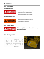
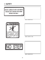
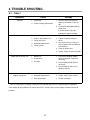
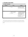
OPERATOR’S MANUAL
ANY PICTURES CONTAINED WITHIN THIS OPERATOR'S MANUAL THAT
DEPICT SITUATIONS WITH SHIELDS, GUARDS, RAILS, OR LIDS REMOVED
ARE FOR DEMONSTRATION ONLY. HAGIE MANUFACTURING STRONGLY
URGES THE OPERATOR TO KEEP ALL SHIELDS AND SAFETY DEVICES IN
PLACE AT ALL TIMES.
OPERATOR’S MANUAL
FOR
HAGIE BLADE STORM FLAIL MOWER
HAGIE MANUFACTURING COMPANY
721 CENTRAL AVENUE WEST
BOX 273
CLARION, IOWA 50525-0273
(515) 532-2861
COVERS:FLAIL MOWER ATTACHMENT OPTION NUMBERS: U80107
11-09 493433
Blade Storm Flail Mower
Operator and Service Manual
1.
TO THE OWNER ................................................................................................... 1
2.
OPERATOR RESPONSIBILITIES ......................................................................... 2
3.
SAFETY ................................................................................................................. 3
3.1. Warning symbols .............................................................................................................................................................................................3
3.2. Safety instructions ...........................................................................................................................................................................................4
3.3. Risk factors ......................................................................................................................................................................................................10
3.4. Danger zones ..................................................................................................................................................................................................10
3.5. Warning symbols .............................................................................................................................................................................................10
4.
INTRODUCTION ................................................................................................... 17
4.1. Dimensions ......................................................................................................................................................................................................17
4.2. Flail mowers ....................................................................................................................................................................................................18
4.3. Auxiliary oil cooler ...........................................................................................................................................................................................18
4.4. Quick couplers .................................................................................................................................................................................................19
4.5. Hydraulic pumps...............................................................................................................................................................................................19
5.
OPERATION .......................................................................................................... 20
5.1. Preparing for operation ....................................................................................................................................................................................20
5.2. Connecting the flail mower to the tractor ..........................................................................................................................................................21
5.3. Disconnecting the flail mower from the tractor .................................................................................................................................................22
5.4. Pre-operative inspections ................................................................................................................................................................................23
5.5. Operating the flail .............................................................................................................................................................................................25
5.6. Unfolding the mower heads ..............................................................................................................................................................................27
5.7. Using the flail controls ......................................................................................................................................................................................28
5.8. Mowing with the flail ........................................................................................................................................................................................29
5.9. Transporting the flail mower ............................................................................................................................................................................30
6.
TIGHTENING TORQUES ....................................................................................... 31
7.
MAINTENANCE ..................................................................................................... 32
7.1. Maintenance precautions ................................................................................................................................................................................32
7.2. Daily maintenance checks ...............................................................................................................................................................................33
7.3. Inner and outer lift base pivot points................................................................................................................................................................34
7.4. Adjusting the cutting height .............................................................................................................................................................................35
7.5. Greasing the cutter shaft .................................................................................................................................................................................35
7.6. Greasing the ground roller shaft ......................................................................................................................................................................36
7.7. Greasing the idler tension arms.......................................................................................................................................................................36
7.8. Idler tensioner ..................................................................................................................................................................................................36
7.9. Daily maintenance schedule............................................................................................................................................................................36
8.
TROUBLE SHOOTING .......................................................................................... 37
8.1. Table 1 ............................................................................................................................................................................................................37
9.
PARTS .................................................................................................................. 38
FAX PAGES ...................................................................................................... ....
Blade Storm Flail Mower
Operator and Service Manual
1. TO THE OWNER
TO THE OWNER
Thank you for choosing the Blade Storm flail mower!
This operator’s manual is intended for both beginner and experienced operators. It is recommended that,
before starting the machine, the operator read this operator’s manual to master the efficient and economic use
of the machine, even if the operator has worked with an equivalent machine previously.
The principles introduced in this manual apply to the use of this machine only. The persons responsible for
airfield maintenance are also responsible for properly adapting these principles for practical use.
The information contained in this manual is based on the facts available at the time of its compilation. This
manual is intended for operators of Blade Storm equipment only. Reproducing the manual in any form without
prior authorization from Hagie is strictly prohibited.
Hagie Manufacturing Company reserves the right to make changes in the design and material of any subsequent piece of equipment without obligation to existing units.
We thank you for choosing Hagie and assure you of our continued interest in its satisfactory operation for
you. If we might be of assistance to you, please call us.
We are proud to have you as a customer.
1
2. OPERATOR RESPONSIBILITIES
Before starting to use the machine, familiarize yourself with the contents of this manual, paying special attention to the SAFETY section,
regardless of whether or not you have operated similar equipment.
NOTICE
The operator of the driving machine bears the responsibility for the maintenance and safe use of the equipment. To ensure proper and effective functioning of the machine, the instructions provided in this manual must
be followed carefully. This is also required for the guarantee to be valid.
The safety instructions contain a summary of the instructions and rules that must be followed whenever working with the machine. However, these instructions do not replace the various statutory occupational and traffic
safety requirements that may be in force on different sites.
Everything possible has been done to ensure that the information contained in this manual is correct and that
the manual contains all necessary warnings. Neither Hagie Manufacturing nor its representatives assume any
direct or indirect liability for damages caused by the information contained in this manual or lack of any warning
issued therein or for any form of damage caused by the use of their tools or components.
Due to constant product development, Hagie Manufacturing reserves the right to alter any machine function or
structure after the publication of this manual.
Keep this manual in a convenient place for easy reference when problems arise. This manual is considered a
permanent fixture with this piece of equipment. In the event of resale, this manual should accompany the
equipment. If you do not understand any part of the manual or require additional information, contact the Hagie
Customer Service Department:
Hagie Manufacturing Company
721 Central Ave West
PO Box 273
Clarion, Iowa 50525
(515) 532-2861
www.hagie.com
2
3. SAFETY
3.1. Warning symbols
The following warning symbols are used in this manual to emphasize points of great importance, which are to
be noted.
Imminent death/critical injury
Neglecting the safety measures may cause critical
injury or death.
Serious injury or possible death/
equipment damage
Incorrect operation or servicing of the machine may
cause damage to the machine or serious personal
injury.
Possible injury/equipment damage
Incorrect operation or servicing of the machine may
cause damage to the equipment. Possibility of injury.
Note
Pay attention to specific instructions.
NOTICE
3
3. SAFETY
3.2. Safety instructions
Read and familiarize yourself with all warnings and safety instructions
specified in this manual.
The machine may not be operated, repaired or serviced by a person, who
is unqualified, tired, ill or intoxicated.
The operator of the machine is always responsible for safety. The operator
must have adequate training on the machine and its operation.
Keep a first-aid kit at hand at all times. Check the contents of the first-aid
kit regularly and update the contents if necessary.
When moving, the machine may cause personal injury in the operating
area. During operation, no person is to stay in the operating area, on top
of, or on the steps or platforms of the machine.
Do not step between the coupling and the tractor when connecting.
Check that there are no persons under the equipment when lowering it.
Danger of clamping!
•
Space between the coupling and the tractor
Never service or repair the machine alone.
When working under the machine, make sure that it is securely and safely
supported. Danger of clamping!
4
3. SAFETY
Do not allow unauthorized persons inside the tractor cab when you are servicing the machine.
When making adjustments to the machine, adhere to the given instructions
and settings. Appropriate use of the machine increases its service life.
Always use original spare parts and components.
NOTICE
Keep in mind the following facts and hazards associated with high pressure
hydraulics:
•
Use protective clothing and goggles when servicing the hydraulic system.
•
Escaping high-pressure oil may penetrate the skin and cause severe
injuries and accidents. The oil spray can be very difficult to detect.
•
Oil operating temperature can be very high.
•
The hydraulic system must be depressurized before it can be opened.
Before servicing, ensure that the attachment has been lowered and
that the cylinder is in a static state.
•
Clean all connections and components, and store the system free of
impurities.
•
Check the tightness of hose connections. Replace worn or damaged
hoses. New hoses must meet the requirements set by Hagie Manufacturing.
•
Do not discard oil into the environment!
If welding is necessary, take the following precautions:
•
Remove the battery cables of the tractor before welding.
•
Always use a welding mask and protective clothing.
•
Be careful not to become part of the welding electrical circuit.
•
Always keep fire-extinguishing equipment close at hand.
•
Welding gases are hazardous to health; do not breath in the gases.
5
3. SAFETY
The operator and support personnel should wear hard hats, safety shoes,
safety glasses, and proper hearing protection at all times for protection
against injury including injury from items thrown by the equipment.
Do not modify or alter this equipment. Do not allow anyone else to modify
or alter this equipment, any of its components, or its function.
Prolonged exposure to loud noise may cause permanent hearing loss!
Transport only at safe speeds. Do not operate the machine over recommended speeds or those recommended with the attachment equipment. Do
not operate the machine over speeds in which you feel comfortable!
Routinely check all moving parts for wear and damage. Replace when necessary with only authorized parts. Look for anything that may be loose, broken, or missing.
KEEP AWAY FROM MOVING PARTS! To prevent entanglement, serious
injury, or possible death, maintain a safe distance from moving parts. Do
not wear loose fitting clothing that may be blown or sucked into moving
parts.
Do not allow children to play on or around equipment!
Never operate the equipment while under the influence of alcohol or drugs.
Do not allow someone else to operate the equipment if they are suspected
to be under the influence of drugs or alcohol.
Mow in conditions where you have unobstructed visibility only. Do not mow
in conditions where there is not enough light (natural or artificial) or in foggy
conditions. If you can not clearly see 100 yards in front of you and to the
sides of you do not operate the equipment.
This equipment is capable of throwing objects 100 yards! Do not operate
the equipment if bystanders are within the safe operating zone!
6
3. SAFETY
All safety guards and devices must be in place while operating the equipment. Replace all missing or broken guards before operating the equipment.
The rotating part of this attachment have been designed for rugged use.
However, the blades can fail upon impact with heavy, solid objects such as
metal guard rails and concrete structures. Impact could cause the broken
objects to be thrown outward at very high velocities. To reduce the possibility of property damage, serious injury, or death, never allow the cutting
blades to come into contact with such obstacles.
Use extreme caution when operating near loose objects such as gravel,
rocks, wire, or other debris. Inspect the area before mowing. Remove any
hazards to prevent machine damage and bodily injury. Clearly mark any
object that can not be removed so that it is easily avoidable by the operator. Stop mowing immediately if the cutting blades come into contact with a
foreign object. Repair any damage and make certain the rotor or blade carrier is balanced before resuming mowing.
Do not operate the mower if contact has been made with items such as
rope, wire, cable, or chains. These objects become entangled around the
operating parts of the mowing head and then swing outside the housing at
greater velocities than the cutting blades. This could be a very hazardous
situation and could result in serious injury or death. Avoid such a situation
by removing any hazard from the site before mowing.
Do not mow at speeds faster than what the attachment or machine is capable of. Do not mow at speeds faster than your ability to safely navigate the
terrain.
Avoid mowing in reverse direction. Objects and people are not visible when
operating the machine in reverse. If the machine must be operated in reverse direction, make sure that the area is clear of all obstacles and operate the machine at a slow speed.
7
3. SAFETY
Replace bent or broken blades with new ones. NEVER TRY TO WELD OR
STRAIGHTEN A DAMAGED BLADE!
Do not put hand or feet under the mower decks. Contact with the cutting
blades could result in a serious injury, dismemberment, or even death. Stay
away until motion has stopped!
Do not operate the mower if excessive vibration exists. With the mower and
the machine off, inspect the mower to determine the source of the vibration.
Replace any missing blades immediately. Operating the mower with excessive vibration could result in component failure and broken objects being
thrown out at high velocities.
Transport the attachment with it fully raised and the wings in the folded position. Make sure that they have been locked into place with the appropriate
tools.
Do not allow the blades to turn while the wings are raised.
Never leave the attachment in the upright position while it is unattended.
Accidental hydraulic failure may cause a sudden drop of the wings creating
a potential injury or death by crushing.
Relieve hydraulic pressure before doing any service or maintenance to the
attachment. Do not allow a person under a folded wing unless it is locked
up or supported.
Do not approach an attachment unless the machine is turned off and all
motion has stopped.
Be aware of your surroundings when lowering the wings. Make sure that
there are no bystanders that could potentially be hit with the wing during
the unfolding process. Make sure that there is enough clearance when unfolding near a building or other obstacle.
8
3. SAFETY
The flail cutter shaft is designed for standard rotation. Never operate the
cutter shaft in the reverse rotation.
The rotating parts of this machine continue to rotate even after it has been
shut off. The operator should remain in his seat for 60 seconds after the
brake has been set and the tractor turned off and all evidence of rotation
has ceased.
The Blade Storm flail mower is manufactured by Tiger Corporation for the use on Hagie Manufacturing Company machine model GST 20. This manual was written to incorporate both company’s specifications and instructions.
Tiger mowers use balanced and matched system components for blade carriers, blades, cutter shafts,
knives, knife hangers, drive train components and bearings. These parts are made and tested to Tiger specifications. Non-genuine “will fit” parts do not consistently meet these specifications. The use of “will fit” parts may
reduce performance, void warranty, and present a safety hazard. Use genuine Tiger mower parts for economy
and safety.
Tiger is a registered trademark of Tiger Corporation, Sioux Falls, SD.
Blade Storm is a trademark of Hagie Manufacturing Company, Clarion, IA.
9
3. SAFETY
3.3. Risk factors
Personal injury risks
•
Insufficient training on correct use of the machine
•
Unauthorized persons in the operating area
•
Negligence of occupational safety regulations
•
Negligence of operating and service instructions
•
Incorrect operation of the machine
Equipment damage risks
3.4. Danger zones
Minimum safety distance from the machine during
operation is 100 yards!
3.5. Warning symbols
21405– MOWER DECK
10
3. SAFETY
22839– MOWER DECK
22840– INSIDE OF CAB
22865– MOWER DECK
11
3. SAFETY
24028– MOWER DECK
33743– INSIDE OF CAB
42350– MOWER DECK
12
3. SAFETY
6T3217– MOWER DECK
6T3219– INSIDE OF CAB
6T3220– FRONT PUMP MOUNT
13
3. SAFETY
6T3224– MOWER DECK
6T3230– INSIDE OF CAB
6T3233– HYDRAULIC TANK
14
3. SAFETY
6T3234– INSIDE OF CAB
6T3236– MOWER DECK
6T3242– INSIDE OF CAB
15
3. SAFETY
– MOWER DECK
16
4. INTRODUCTION
4.1. Dimensions
122.66 in.
92.01 in.
105.00 in.
294.59 in.
17
4. INTRODUCTION
4.2. Flail mowers
There are three separate flail mowers to the assembly. The left, center, and right flail mowers are capable
of being operated individually as well as together.
Each of the mowers has several cutting blades strategically placed to keep balance during operation. If one
of these blades is missing, it could cause an unbalanced
Right
situation that if not attended to may result in more severe damage. Make sure that all blades are properly
attached and in good repair before operating the flail.
4.3. Auxiliary oil cooler
There is an auxiliary oil cooler located on the right
side of the machine behind the solution tank. The auxiliary cooler is necessary because of the extra flow of oil
to the flail mowers.
18
Center
Left
4. INTRODUCTION
4.4. Quick couplers
A
The flail’s hydraulic hoses and the machine are designed for easy connection and disconnection with quick
couplers.
There are 6 couplers on the underside of the machine
behind the solution pump (A). There is also a connection point in the front of the machine (B).
B
4.5. Hydraulic pumps
C
The hydraulic system also has an extra pump stack
(C) on the engine in order to be able to supply the
power needed to operate the flail mowers.
19
5. OPERATION
5.1. Preparing for operation
Review the safety decals placed on the flail mower
and inside the cab. These decals should be understood
by each operator of the machine along with the safety
A
and operation section of this book. The decals should
be kept in good condition and replaced if damaged,
missing, or faded.
Make sure that all pivot points have been greased.
Make sure that all hoses are secured with zip ties (figure
A). Replace broken zip ties if necessary. Make sure that
there are no points of friction between the hose and another surface. If the hose is rubbing against a surface,
place something between the hose and the surface and
secure it with zip ties.
Before operating the mower, the cutter head and lift
base should be slowly moved throughout the full range
BEFORE starting or operating the tractor you
of motion. Watch for any condition that would cause
must read and understand the safety and operation sections of this manual completely.
pinching or excess stress on the hoses.
Take the tractor to a place free of loose objects on
the ground. Operate the cylinders through their full
range of motion again, to clear the lines of air. Follow
the instructions in the operation section to operate the
mower. Vibration of the mower should be minimal at all
times. After a 5 minute test run, the knife bolts should be
retorqued and once again after the first few hours of
operation.
Without starting the mower, practice positioning the
mower deck. When you feel comfortable at controlling
the position of the mower, return the mower to the travel
position, and transport the mower to the desired mowing
location.
20
5. OPERATION
5.2. Connecting the flail to the tractor
Attachment change over instructions
1. Once the boom is removed from the tractor (see
tractor manual), the tractor will be ready to attach
the flail mower.
2. Pull up to the flail and shut off the engine.
3. Remove flail attachment side cover and connect the
electrical connection.
4. Connect all hydraulic hoses from the flail to the tractor. Check all hoses on the flail for leaks.
5. Make sure the quick attach lock pins are open.
6. Start the engine and move slowly toward the attachment. You may have to deflate the air bags to get
under the quick attach hooks on the flail.
7. Raise the left and right mower heads to allow the
attachment to “hook” onto the tractor.
8. Once the attachment has dropped into place, shut
the engine off and check that the lock pins are
locked and all connections are secure.
9. Connect the turnbuckles.
10. Start the machine and place activate the WORK
MODE and FLOAT switches.
11. You are now ready to mow.
21
5. OPERATION
5.3. Disconnecting the flail from the tractor
Attachment change over instructions
1. Pull the tractor and flail up to where you intend to
store the flail. The flail side mowers must be down in
the operating position for storage.
2. With the flails running, float all the heads to the
ground.
3. Once all the heads are on the ground, shut the flail
motors off.
4. Shut the tractor engine off. Disconnect the turnbuckles and unlock the quick attach lock pins.
5. Start the engine and turn the FLOAT switch off.
6. Lower the left and right flail heads to raise the attachment off the quick attach hooks. You may have
to release some air out of the air bags to get low
enough to back away from the attachment.
7. Shut off the machine again.
8. Disconnect the hydraulic hoses. Use the caps provided to cover hose ends.
9. Disconnect the electrical connectors and replace the
flail attachment side cover.
10. Back away from the attachment.
22
5. OPERATION
5.4. Pre-operative inspections
The operator is responsible for inspecting the flail for
broken or missing parts, shields, leaks, or any other
damage. These checks should be performed before operation and should be repeated at the end of the day.
This way any fluid leaks and damages can be detected
more quickly and repair procedures can be planned well
in advance.
1. Check the condition of the structures
Check the condition of the structures
•
Welded seams
•
Tightness of bolts
•
Possible wear
•
Damage
•
Shields
•
General structure of the flails
2. Check the condition cutter blades
Check the wear of the flail cutting blades. Do attempt
to sharpen or repair damaged or dull blades. Replace
the blades in complete sets only. Failure to do so may
result in an poor balance and a vibration that could
cause severe damage to the mower.
Make sure that all blades are properly secured to the
cutter shaft. Replace all the blades even if only one is
missing. Never operate the flail with a missing blade.
Check to make sure that all nuts and bolts are not loose.
23
5. OPERATION
3. Other daily maintenance checks
•
Lubricate pivot points
•
Check hydraulic fittings for leaks
•
Check/adjust belts
•
Check the hydraulic fluid level
•
Lubricate cutter shaft and ground roller bearings
24
5. OPERATION
5.5. Operating the flail
Once the flail is at the intended mowing
site, check to make sure that the flail
NOTICE
height is appropriate for the job.
Lower the mower deck so that it is slightly above the
material to be cut. This allows the mower to start while it
is not under a load.
The mower deck should be adjusted so that part of
the weight is carried by the ground roller. This allows the
roller to follow the contour of the ground more easily
during operation.
To ensure a desirable cut, the speed of the engine
should be maintained at approximately 1800 to 2200
RPM. If the engine slows to below 1800 RPM, shift to
the next lower gear. The engine should not be operated
more than 2400 RPM at any time.
Sharp cutting blades will perform better in tougher
conditions than ones that are worn. If any of the flail
mower decks begin to vibrate, shut down the mowers
and the tractor immediately. Once rotation has stopped,
check the spindles for damaged cutting blades or an
obstruction, such as wire or rope wrapped around the
spindle.
Do not operate the mower heads with any person
within the 300 feet safety zone. If a person comes into
the safe zone, shut the mowers down immediately!
If a problem arises that causes the tractor to stall,
disengage the mower, start the tractor, raise the mower
from the cut. Shut the tractor off and inspect the mower,
blades and disk for damage before engaging the mower
again.
25
5. OPERATION
If the blades become jammed or stop turning, raise
the heads slightly or back the tractor up. This should
clear the obstruction. If this does not allow the cutter
heads to begin turning, shut the cutter heads and the
tractor off and set the parking brake. Wait until all motion has stopped and then manually clear the cutter
heads.
Follow the maintenance instructions for lubrication
intervals and procedures. Check the bolts and tighten
them if necessary after the first day of operation. Regularly check the bolts to ensure that they do not become
loose and cause damage.
26
5. OPERATION
5.6. Unfolding/folding mower heads
Be sure to remove the safety pins from
the flail mower heads before attempting
NOTICE
to lower them into operating position!
In order to be able to unfold the mower heads from
the transport position, you must run the heads all the
way in by activating the left and right fold switch on the
control handle.
Once the heads are folded all the way in, you must
raise them up as far as you can. This is to disengage
the hook from the stop latch.
Unfold the heads by engaging the left and right fold
switches on the control handle in the “OUT” position. If
the hook does not disengage the latch, repeat the process until the heads unfold. Continue to manually unfold
the heads until they are approximately at a 45° angle
(from vertical) and engage the FLOAT mode switch.
This will allow the heads to ease to the operating position evenly. It is not recommended that this process be
performed manually as the heads can be lowered incorrectly causing severe damage.
To fold the heads into transport position, disengage
the FLOAT mode switch. Raise the heads to the end of
cylinder travel using the left and right raise switch on the
control handle. Then, using the left and right fold in
switch on the control handle, fold the mower heads all
the way in until they contact the stop. Once they are
folded all the way in, lower the heads so that the stop
hook engages.
27
5. OPERATION
5.7. Using the flail controls
A. All mower heads raise
B. All mower heads lower
C. Left mower head raise
D. Left mower head fold out
K
A
E. Left mower head lower
J
B
F. Left mower head fold in
C
I
G. Master on/off switch
D
H
H. Right mower head lower
G
F
I.
Right mower head fold in
J.
Right mower head fold out
E
K. Right mower head raise
L. Work mode
M. Float mode
N. Left flail mower individual on/off switch
L
O. Center flail mower individual on/off switch
O
P. Right flail mower individual on/off switch
N
The WORK mode switch must be acti-
NOTICE
vated to provide power to the flail.
28
P
M
5. OPERATION
5.8. Mowing with the flail
Before starting to mow with the flail mower, the area
to be mowed should be inspected for any obstructions
or debris that may cause damage to the flail blades, machine, operator, or other structures.
The mower must be in operating position to mow. The
WORK mode and the FLOAT mode switches must be
activated. The tractor’s parking brake must also be released in order to engage the flails.
The mower heads are capable of being run individually or all at once. The mower heads are turned on individually by activating the spray switches on the side
console.
To activate the left mower head, depress the top of
the third spray switch. To deactivate the left mower
head, depress the bottom of the third spray switch.
To activate the center mower head, depress the top
of the fourth spray switch. To deactivate the center
mower head, depress the bottom of the fourth spray
switch.
To activate the right mower head, depress the top of
the fifth spray switch. To deactivate the right mower
head, depress the bottom of the fifth spray switch.
Once the mower heads have been activated, the
MASTER SPRAY switch on the control handle must be
activated to engage the hydraulic motors.
The mower heads can be moved simultaneously by
activating the ALL MOWER HEAD RAISE (transom lift)
switch on the control handle. If a head is not activated
(turned off on the spray switch console), it will not move
during this function.
29
5. OPERATION
5.9. Transporting the flail mower
The flail should only be transported between job sites
in the transport position (the mower heads in the vertical
position). Never operate the flail mowers in the vertical
position!
30
6. TIGHTENING TORQUES
31
7. MAINTENANCE
7.1. Maintenance precautions
The performance of the flail mower depends on how it
is maintained. Following a regular maintenance schedule will result in the best performance and longest life of
the mower.
•
Make sure that the end of the grease gun and the
end of the grease zerk are clean of any debris that
could enter the lubrication system. Debris or dirt that
enters into bearings when greasing will cause immediate damage!
•
Use a hand pump grease gun when lubricating the
mower. A power grease gun may force too much
grease into an area and cause distortion of seals
and over greasing of bearings.
•
Be aware of maintenance indicators such as vibrations, noises, reduced performance, etc. Take action to correct any problems immediately.
•
Release of energy from pressurized systems may
cause inadvertent actuation of the hydraulic cylinders. Before disconnecting any hoses, relieve pressure by turning the tractor off and setting the heads
on the ground.
•
Do not use hands to check for hydraulic hose leaks!
Hydraulic fluid escaping under pressure can have
sufficient force to penetrate skin and cause serious
injury. If fluid is injected into skin, it must be surgically removed within a few hours to prevent gangrene from setting in.
•
Make sure all hoses and fittings are in good condition before pressurizing the hydraulic system.
32
7. MAINTENANCE
7.2. Daily maintenance checks
The intervals at which regular servicing should be done are based on hours of operation. Use the tractor’s
hour meter to determine when regular servicing is required.
Point of Service
Action
Pivot points
Lubricate
Inject grease until it appears at ends
Hydraulic fittings
Check for leaks
Tighten when needed. Do not use
hands to check for leaks, see maintenance precautions.
Cutting blades
Check
Inspect for missing or damaged
blades, change as needed.
Cutter shaft mounting bolts
Check
1/2” x 2” torque to 84 ft. lbs.
Blade mounting bolts
Check
Retorque to blade replacement specifications.
Belts
Check/adjust
Mower deck
Check
Cutter shaft and ground roller
Lubricate
33
Comments
Check if broken, tighten as required
Retorque bolts to specifications.
Grease as instructed in detailed maintenance section.
7. MAINTENANCE
7.3. Inner and outer lift base pivot points
Locate the grease zerks on the inner and outer lift
base pivot bosses. Inject a lithium based grease conforming to NLGI 2-ISO 320 specifications into each zerk
until it protrudes from joints. Grease all pivots daily or
every 8 hours of service.
With the mower head lowered, locate the grease
zerks on the linkage and pivot bosses. Inject lithium
based grease that conforms to NLGI 2-ISO 320 specifications until it protrudes from the ends. With the mower
heads in this position it is also possible to grease the lift
base cylinder anchors and pins. Now raise the mower
head to expose the remaining zerks on the deck tilt linkages and on the other end of the cylinder.
34
7. MAINTENANCE
7.4. Adjusting the cutting height
Loosen the four ground roller bracket lock nuts.
Loosen the adjustment rod lock nut and turn the adjust-
A
ment rod to adjust the cutting height. The cutting height
is indicated by the end of the adjustment rod on the cutE
ting height decal. When cutting height has been
B
C
achieved, tighten the ground roller bracket lock nuts and
D
D
the adjustment rod lock nut securely. Be sure both sides
of the flail are adjusted the same.
A. Adjustment rod
B. Adjustment rod lock nut
C. Cutting height decal
D. Ground roller bracket lock nuts
E. Ground roller bracket
7.5. Greasing cutter shaft
Locate grease zerks on each end of cutter shaft(s),
these are located on the bearing cover. Normal conditions require one or two pumps in each bearing, using a
lithium based grease conforming to NGLI 2– ISO 320
specifications. This is to be done with a standard grease
gun daily or at 8 hour intervals. Caution: Over greasing may cause premature seal failure.
35
7. MAINTENANCE
7.6. Greasing ground roller shaft
Locate grease zerks on each end of roller tubes at
lower rear of head. Normal conditions require one or two
pumps in each bearing, using a lithium based grease
conforming to NGLI 2-ISP 320 specifications. This is to
be done with a standard grease gun daily or at 8 hour
intervals. Caution: Over greasing may cause premature seal failure.
7.7. Greasing idler tension arms
Locate the access holes and grease zerks in the belt
shields of the flails. Normal conditions require one pump
of a multipurpose grease. This is to be done with a standard grease gun daily or at 8 hour intervals.
7.8. Idler tensioning
Locate the tensioning rod for each flail. Loosen the
locking nut. Turn the adjusting nut until the washer in
between the spring and nuts is flush with the spring
housing or guide. Tighten locking nut securely. For standard cut on side flail adjust until the spring washer is
flush with the top of the spring housing, as shown below.
7.9. Daily maintenance schedule
Located in the back of this book is a daily maintenance schedule. Please make copies of the page and
use it to record daily maintenance procedures and other
maintenance issues.
36
8. TROUBLE SHOOTING
8.1. Table 1
Symptoms
Vibration
Cause
1. Loose belts
2. Cutter assembly unbalanced
Remedy
1. Check all bolts and tighten to
torque specifications in this section.
2. a) Check for damaged blades or
cutter shaft.
b) Check for wire, rope, etc.,
entangled in cutter assembly.
Mower will not lift
1. Hydraulic fluid low
1. Check and refill hydraulic fluid.
2. Leaks in the hydraulic line
2. Tighten or replace fittings or
hoses.
3. Faulty relief valve
4. Kinked or blocked hose
5. Faulty cylinder
3. Check pressure line. Line pressure in control valve should be at
least 2250 psi.
4. Clean or replace lines.
5. Inspect, repair, or replace cylinder.
Mower will not start or run
1. Blown fuse
1. Check fuses between mower
switch and ignition. Replace if
necessary.
2. Low oil level
3. Line leak
2. Check hydraulic fluid and fill if
necessary.
3. Check all fittings and lines, retighten or replace.
Oil temperature rises above 200 1. Low oil level
degrees Fahrenheit
2. Kinked or blocked hose
3. Worn pump/motor
1. Bring oil to proper level.
2. Inspect, repair, replace hoses.
3. Disable and repair.
NOTE: If flow meter is available, check pressure and flow volume for all suspected hydraulic problems.
If the solution to your problems can not be found in this section, please call the Hagie Customer Service department.
37
8. TROUBLE SHOOTING
8.1. Table 1 (continued)
Symptoms
Motor runs but will not cut
Cause
1. Belts
Remedy
1. Inspect belts and pulleys. Replace
belts and repair as needed.
2. Tensioner
2. Adjust tensioner nut until flat
washer is flush with top of guide.
Motor turns slowly or not at all
1. Contaminants restricting spool
movement in valve body.
2. Suction lines obstructed.
3. Low oil level.
1. Remove large nut on side of large
valve block. Remove spring, and
use needle nose vise grip to pull
spool from block. Check block and
spool for contaminants and
scratches. Clean parts and replace if scratched.
2. Check for kinks or obstructions in
suction hose.
3. Check hydraulic fluid level.
NOTE: If flow meter is available, check pressure and flow volume for all suspected hydraulic problems.
If the solution to your problems can not be found in this section, please call the Hagie Customer Service department.
38
9. PARTS
9.1. About the drawings
The drawings on the following pages are the property of Tiger Corporation and Hagie Manufacturing Company. Each company, separately, reserves the right to make changes to the design of the mowers or their
function without obligation to existing attachments. The Tiger drawings may not exactly represent the attachment as it is used on the Hagie GST 20 machine.
There are Parts Order Fax sheets in the back of this manual, please keep a blank copy for future ordering
needs.
If you have any questions about your attachment or need assistance ordering parts, please call Hagie Customer Service Department.
39
9. PARTS
9.2. 102” Rear mower cutter assembly
40
9. PARTS
9.3. Hydraulic deck motor
41
9. PARTS
9.4. Lift cylinders
42
9. PARTS
9.5. Standard duty side flail drive assembly
43
9. PARTS
9.6. 102” Rear flail standard rotation
44
9. PARTS
9.7. Heavy duty 102” rear flail reverse rotation
45
9. PARTS
9.8. 102” Rear flail drive assembly
25
23
22
2
24
1
18 19
20
6
21
16
5
15
7
6
26
14
27
13
3
12
8
4
9
11
10
ITEM
P/N
QTY
DESCRIPTION
ITEM
P/N
QTY
DESCRIPTION
1
TF3023
2
V-BELT (630)
15
TF3610
1
BUSHING, REAR FLAIL, IDLER
2
31286A
1
SHIELD, BELT, TRF, HD
16
6T2418
1
HEX NUT, 1/2” NC
3
21988
4
LOCKWASHER, 3/8”
17
4
21630
4
CAPSCREW, 3/8” X 1, NC
18
TF3605
1
PIN, IDLER ARM 3/4” X 4-1/4”
5
31740
1
NYLOCK NUT, 20MM (2.5PITCH)
19
6T3004
1
R-CLIP (HAIRPIN COTTER, 3/16”)
6
24881
2
LOCKWASHER, 20MM
20
TF1180
1
ARM, IDLER (REAR FLAIL/RR)
7
31295
1
SHEAVE, IDLER ASSY, 6.3
21
28572
1
KEY, 1/4” SQ X 2”
8
TF3011
1
BUSHING, QD, SK 2-3/16”
22
30049
1
BUSHING, QD, SK 1-1/4, 1/4 KEY
9
TF3043
1
SHEAVE, 7.5
23
28570
1
SHEAVE, 9.0
10
21700
2
HEX NUT, 1/2”, NF
24
28399
1
CAPSCREW, 20MM X 80MM (2.5PITCH)
11
27938
1
BUSHING, MACH, 1 OD X 1/2 ID X 14 GA
25
22046J
1
BONNET, 102, HD, RCM
12
TF3620A
1
SPRING, TENSIONER
26
21732
1
CAPSCREW, 1/2 X 1-3/4, NC
13
25175
1
RAW RD, THREADED, 1/2-20
27
TF1707C
1
CUTSHFT ASSY, 102 HD
14
PT3611A
1
CLEVIS, 6”
46
9. PARTS
9.9. Side deck motor– high pressure
47
9. PARTS
9.10. Side deck motor
48
9. PARTS
9.11. Side deck motor– high pressure
49
FLAIL ASSEMBLY
Det Qty P/N
Description
1
1 A53338 QUICK ATTACH WLDT
2
1 A54390 GST CONTROL VALVE ASSY FLAIL
3
2 A53450 CYLINDER, 3" BORE X 10" STROKE
4
2 A53452 CYLINDER, 3" BORE X 10" STROKE
5
2 A53451 CYLINDER, 3.38" BORE X 20" STROKE
6
1 A53442 LEFT FLAIL WLDT
7
1 A53328 WING ASSY, LH
8
2 A53462 SHOCK ABSORBER
9
1 A53444 FRONT FLAIL WLDT
10 1 A53443 RIGHT FLAIL WLDT
NS 1 A53336 WING ASSY, RH
NS 1 621558 LEVEL CYLIDER, 3.0X11.0 STS
10
9
8
7
1
2
4
3
5
6
9. PARTS
9.12. Flail assembly
50
9. PARTS
9.13. Flail assembly
51
9. PARTS
9.1.
52
9. PARTS
9.1.
53
9. PARTS
9.1.
54
9. PARTS
9.1.
55
9. PARTS
9.1.
56
9. PARTS
9.1.
57
9. PARTS
9.1.
58
9. PARTS
9.1.
59
PARTS ORDER FAX
FAX
24 hours a day
7 days a week*
Phone 1 (800) 247-4885 Fax 1 (515) 532-3553 Photocopy and fax to Hagie Customer Support Department
SHIP TO:
ORDERED BY/ BILL TO:
Name:_______________________________________ Name:_______________________________________
Co. Name:____________________________________ Co. Name:____________________________________
Street:_______________________________________ Street:_______________________________________
City, State, Zip:________________________________ City, State, Zip:________________________________
Phone:________________ Fax:___________________ Phone:________________ Fax:___________________
HOW TO SHIP:
UPS Ground
Next Day
2 Day
Other:_____________________
3 Day
If "HOW TO SHIP" is left blank, parts will be shipped UPS Ground service. If the part is over 150
pounds, an independent motor carrier will be used.
PAYMENT:
Hagie Account # ** :________________________
American Express
Discover
Visa
C.O.D
Master Card
Signature:______________________________________
Name as it appears on card:_______________________
Card #:_______________________Exp. Date:_________
Year and Model #:_______________________________ Serial #:________________________________________
Item Serial # (if necessary):
Engine (inclde type):__________________________
Hydrostatic Pump(s):__________________________
Wheel Hubs:_________________________________
LF
RF
LR
RR
Wheel Motors:_______________________________
Hagie Part #
Qty.
LF
RF
LR
RR
Description
Check here if you want phone confirmation of parts order.
* Orders received before 3:00 p.m., CST, will be processed the same business day.
Regular business hours are Monday through Friday, 7:00 a.m. through 5:00 p.m.
** If you do not have a Hagie account number, contact the Hagie Customer Service Department and you will
be issued one.
DAILY MAINTENANCE SCHEDULE
The following services should be performed daily or every 8 hours of service, following
the detailed maintenance instructions in the operators manual.
_________
Pivot Points: Inject grease until it appears at ends.
_________
Hydraulic Fittings: Check for leaks with paper or cardboard.
Tighten fitting or replace hoses immediately.
_________
Knives: Inspect for missing or damaged knives, change (only
complete sets) as needed.
_________
Belts: Check, tighten, replace belts as needed.
_________
Main Frame/ Deck: Unless otherwise specified, retorque bolts
according to torque specifications in operators manual.
_________
Cutter Shaft and Ground Roller: Grease as instructed in the
detail maintenance section.
Service performed by:____________________ Date: _____/_____/_______
Hour meter reading: __________
Please record any notes on the back of this page.
*This page may be copied and used as part of the daily maintenance routine.*
NOTES:
41
OPERATOR’S MANUAL
492101
www.hagie.com