1
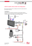
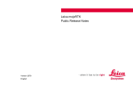
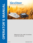
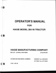
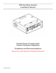
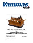
HOW TO GUIDE: Antenna Distance to Fixed Axle This document describes how to set the Antenna Distance to Fixed Axle in the Leica mojoRTK system. This setting is now part of the vehicle setup wizard and needs to be understood for improved performance of the system. The intended audience of this document includes Leica Geosystems’ approved resellers and internal support personnel. Description The Antenna Distance to Fixed Axle is a relatively new setting that needs to be entered into the system. Correctly setting this offset in the Leica mojoRTK console improves line acquisition and on-line performance of the autosteering sub-system. Note that the Antenna Distance to Fixed Axle should not be confused with the Antenna Fore/Aft setting in the Leica mojoRTK Vehicle Settings menu. The Antenna Distance to Fixed Axle is to aid the positioning system in the Leica mojoRTK to provide an accurate speed and direction. The Antenna Fore/Aft setting is used to help the steering control system and is explained separately in Appendix A. Benefits Correctly setting the Antenna Distance to Fixed Axle improves the system’s calculation of the vehicle speed and direction. This in turn improves steering performance of steering systems supported by the Leica mojoRTK system. Although some steering systems will only show moderate improvements, other steering systems will experience greatly improved performance. Limitations Although all steering systems supported by the Leica mojoRTK system will benefit from correctly setting the Antenna Distance to Fixed Axle some systems will not be improved as much as others. Required Items Leica mojoRTK system installed into a vehicle with a supported steering platform. For more information: www.AgGuidance.com Page 1/9 Document #1065 rev1.2 Instructions To set the Antenna Distance to Fixed Axle you will need to get into the Vehicle Wizard in the mojoRTK console. There are two ways to do this: 1. If the console is new or has just been reset to factory defaults the console will start up in the initial setup wizard and the vehicle wizard is a sub set of the set up wizard. In this case progress through the setup wizard as per the Leica mojoRTK user manual until you get to the Ant. Dist. to Fixed Axle section where the instructions below begin to apply. OR 2. You can get into the vehicle wizard from the menus in the Leica mojoRTK console. The steps are: a. From the main navigation screen of the Leica mojoRTK console press OK to get into the main menu b. Select Settings and press OK. c. Select Vehicle and press OK. d. Select Vehicle Wizard and press OK. e. Go through the vehicle wizard as per the Leica mojoRTK user manual until you get to the Ant. Dist. to Fixed Axle section where these instructions below begin to apply. Determining the Value to Enter As the Antenna Distance to Fixed Axle Once you have made your way to the Ant. Dist. to Fixed Axle section of the Vehicle Wizard you need to know how to figure out what value it is that you need to enter into the system. The Antenna Distance to Fixed Axle is the distance along the center line of the vehicle between the red GPS antenna and the non-steering axle of the vehicle (for an articulated tractor, the front axle is used). There is one other thing to be careful of. Depending on the type of vehicle the antenna distance to fixed axle may be positive or negative and it is very important to get this right. Table 1 below shows diagrams of various vehicles and explains the how the offset should be worked out for each one. NOTE: in all these diagrams the antenna is shown on the center line of the vehicle but with the Leica mojoRTK system the antenna will be off to one side. The measurement will be the same if it is made from the antenna to the center line of the fixed axle . For more information: www.AgGuidance.com Page 2/9 Document #1065 rev1.2 NOTE: in all diagrams refer to measurement number 1 for the antenna distance to fixed axle. NOTE: when entering the offset in US Standard or Imperial units the value is entered in inches with quarter inch resolution. For more information: www.AgGuidance.com Page 3/9 Document #1065 rev1.2 Table 1: Examples of antenna distance to fixed axle values for various vehicle types. (In all cases, distance number 1 in the diagrams is the Ant. Dist. to Fixed Axle) 1. Front Wheel Steer In this case the antenna is in front of the fixed axle and therefore the Antenna Distance to Fixed Axle is positive. Examples: +1.01m +39.75” 2. Combine/Harvester In the case shown here, the antenna is in front of the fixed axle so the fixed antenna axle offset is positive. Examples: +0.46m +18.0” NOTE: if the antenna is behind the fixed axle, unlike what is shown here, the offset will be negative. For more information: www.AgGuidance.com Page 4/9 Document #1065 rev1.2 3. Articulated Tractor With an articulated tractor both axles are fixed and for proper control the front axle is used for the offset. However, the antenna is behind the front axle so the Antenna Distance to Fixed Axle is negative. Examples: -1.36m -53.5” 4. Tracked Tractor Use the line between the front-to-rear center of the tracks as the line of the axle. The GPS antenna is usually behind this line and so the Antenna Distance to Fixed Axle is negative. Examples: -1.01m -39.75” For more information: www.AgGuidance.com Page 5/9 Document #1065 rev1.2 5. Self Propelled Sprayer In this case it doesn’t matter if the boom is at the front or the rear of the vehicle as long as in both cases the non-steering axle is the rear axle. NOTE: this is not the case for a Hagie all-wheel steer sprayer. In the case shown the antenna is in front of the fixed axle so the fixed axle offset will be positive. Examples: +5.22m +205.5” For more information: www.AgGuidance.com Page 6/9 Document #1065 rev1.2 Appendix A – The Antenna Fore/Aft Setting The Antenna Fore/Aft setting should not be confused with the Antenna Distance to Fixed Axle as they perform quite different functions. The Antenna Distance to Fixed Axle assists the mojoRTK positioning system to provide a more accurate heading and velocity, where as the Antenna Fore/Aft setting assists the steering control system to acquire and hold the line. The Antenna Fore/Aft setting can help steering systems which are only capable of slowly turning the wheels that steer the vehicle. It helps the vehicle react a little earlier when straightening onto the line during line acquisition. NOTE: Where possible, the Antenna Fore/Aft setting should be left at zero. However, if it is found that a non-zero setting is required it should be kept as low as possible as there are negative effects on system performance as the Antenna Fore/Aft setting gets larger. Refer to Diagram A1 below. Note that the mojoRTK system has the red and black antennas to each side but for the purpose of explaining the Antenna Fore/Aft we will assume that we only have one antenna mounted in the middle. This is essentially what the Red Antenna Offset in the mojoRTK Vehicle Wizard does. The diagram is being used to show two scenarios regarding the Antenna Fore/Aft setting. Scenario 1 – no Antenna Fore/Aft setting (Antenna Fore/Aft set to zero). Scenario 2 – Antenna Fore/Aft setting adjusted to put the control point over the middle of the front axle. When the mojoRTK system is attempting to steer the vehicle onto the line it uses a point on the vehicle called the control point. It is the control point that the system is trying to steer onto the line. For Scenario 1, with the Antenna Fore/Aft set to zero, the control point will be right where the antenna is shown on the diagram. In this case the control point is not on the line so the control system will continue drive the vehicle towards the right to try and get the control point onto the line. For Scenario 2, with the Antenna Fore/Aft set to put the control point over the middle of the front axle, the control point is considered to be on the line, though it is obviously going to go past the line. In reality the control system will have straightened the vehicle to the line before getting into this situation, however, the diagram was drawn to demonstrate the difference between the two control points. For more information: www.AgGuidance.com Page 7/9 Document #1065 rev1.2 If the control point is in front of the antenna then the Antenna Fore/Aft setting will be set to a positive number. If the control point is behind the antenna then the Antenna Fore/Aft setting will be negative (this may be the case on a self propelled sprayer for example). For Scenario 2 the Antenna Fore/Aft will be set to the distance shown by measurement 1 in the diagram and will be positive because the control point is in front of the antenna. To set the Antenna Fore/Aft setting go into the main menu of the mojoRTK system, then go to: Settings Vehicle Antenna fore/aft. Diagram A1 – Antenna Fore/Aft and Control Point NOTE: the mojoRTK system has the antennas to each side but for now consider the antenna to be in the middle. For more information: www.AgGuidance.com Page 8/9 Document #1065 rev1.2 Appendix B - Glossary Antenna Fore/Aft The Antenna Fore/Aft setting is used to move the control point (see below) of the vehicle along the front-to-rear center-line of the vehicle. If the control point is in front of the antenna the Antenna Fore/Aft setting is positive, if the control point is behind the antenna then the Antenna Fore/Aft setting will be negative. Control Point This is mentioned in Appendix A - Antenna Fore/Aft and is a point along the vehicle’s front-to-rear center line. It is this point which the steering control system is trying to get onto the working line. The position of the control point is dependant on the antenna position and the Antenna Fore/Aft setting. Fixed Axle The fixed axle is the non-steering axle. In a front wheel assist or front wheel steer this is the rear axle, on a rear wheel steer it is the front axle. On an articulated tractor it should be considered that the front axle is the fixed axle. On a tracked machine it should be considered to be the line between the front-to-rear center of the left track to the front-to-rear center of the right track. See diagrams in Table 1. Antenna Distance to Fixed Axle The antenna distance to fixed axle is the distance along the center line of the vehicle between the GPS antenna and the fixed axle (see fixed axle definition above). If the GPS antenna is in front of the fixed axle the offset will be positive, if the antenna is behind the fixed axle the offset will be negative. For more information: www.AgGuidance.com Page 9/9 Document #1065 rev1.2