1
OPERATOR'S MANUAL
FOR
HAGlE MODEL 284 HI-TRACTOR
(
HAGlE MANUFACTURING COMPANY
BOX 273 CLARION, IOWA 50525
COVERS MACHINE SERIAL NUMBERS:
(515) 532-2861
046649001 thru 046649200
047749001 thru 047749200
{
10-93 493145
A WORD FROM HAGlE MANUFACTURING COMPANY
Congratulations on your selection of a Hagie Model 284 sprayer.
We
recommend that you study this Operator's Manual and become acquainted with
the adjustments and operating procedures before attempting to operate your
new sprayer.
As with any piece of equipment, certain operating procedures,
service, and maintenance are required to keep it in top running condition.
We have attempted herein to cover all of the adjustments required to fit
varying conditions.
However, there may be times when special care must be
considered.
Hagie Manufacturing company reserves the right to make changes in the
design and material of any subsequent sprayer without obligation to
- existing units.
We thank you for choosing a Hagie sprayer and assure you of our
continued interest in its satisfactory operation for you.
of assistance to you, please call on us.
We are proud to have you as a customer.
- 1 -
If we might be
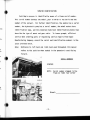
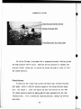
TO THE OPERATOR
The following pages and illustrations will help you operate and
service your new sprayer.
It is the responsibility of the user to read the Operator's Manual and
comply with the safe and correct operating procedures and lubricate and
maintain the product according to the maintenance schedule.
The user is responsible for inspecting the machine and having parts
repaired or replaced when continued use of the product causes damage or
excessive wear to other parts.
Keep this manual in a convenient place for easy reference when
problems arise.
If you require additional information or service, contact
the Service Department at:
Hagie Manufacturing Company
P.O. Box 273
Clarion, Iowa 50525
(515)532-2861
- 2 -
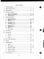
TABLE OF CONTENTS
I.
Safety Precautions
4 - 7
II.
Sprayer Identification .....................................• 8 - 9
III. Specifications .............................................• 10 - 12
IV.
Preparing to Operate
A.
B.
c.
V.
VI.
Wheel Tread Row Spacing
13 - 16
Hydraulic Tread Adjust .................•.......•...•..• 17 - 18
Attaching Booms
19 - 21
Operating Information
A.
B.
C.
Starting the Engine ...................................• 22 - 23
Hydrostati c Dri ve
24 - 26
Hydraulics
27
D.
E.
F.
Air Cond it ion i ng
28 - 29
Tachometer .....•...................................•..• 30
Air Suspended Seat ...............................•....• 31
G.
H.
I.
Emergency Exi t .....................................•... 31
Solution Tanks .......................................•• 32
Agitation ........................................•....•33
J.
Spray System.........................................•. 34 - 35
Calibration
36 - 38
VII. Transporting
A.
Driving ................•........•...................... 39
B.
Trailer
40 - 41
C.
Towing
42
VIII.Service and Maintenance ...................................•. 43 - 49
IX.
Storage
X.
Trouble Shooting
XI.
50 - 51
A.
Engine .............................................•... 52
B.
Spray System.........................................•. 54 - 55
C.
Hydrostatic System
56 - 57
D.
Hydraulic System
58
E.
Electrical System.........................•...........• 59
Limited Warranty
60 - 61
- 3 -
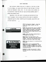
SAFETY PRECAUTIONS
Most accidents, whether they occur in industry, on the farm, at home,
or on the highway, are caused by the failure of some individual to follow
simple and fundamental safety rules.
For this reason, most accidents can
be prevented by recognizing the real cause and doing something about it
before the accident occurs.
Regardless of the care used in the design and construction of any
type of equipment, there are many conditions that cannot be completely
safeguarded against without interfering with reasonable accessibility and
efficient operation.
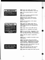
STUDY this Operator's Manual. Learn how
to use the sprayer controls for safe
operation.
DO NOT make modifications such as weldments)
add-ons (adaptations or changes from the
original design of sprayer). Such changes
and/or modifications may become safety
hazards to you and to others and will void
all warranties.
ALWAYS select the widest tread setting to
fit between the crop rows.
NEVER adjust the tread center on the
sprayer until the wheels have been properly
blocked. Loosen the leg clamp bolts only
enough for the leg to slide on the frame.
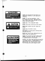
CAUTION
NEVER leave the sprayer in a raised position
unattended.
NEVER adjust tire air pressure without
knowing the proper recommendation. Do not
attempt to dismount or mount a tire unless
you have the proper equipment and experience
to perform the job.
BE SURE the ladder and operator's station
are clean and dry to help prevent personal
injuries.
AWARNING
NEVER by-pass the safety start switch.
Start engine from the operator's seat only.
NEVER run the sprayer engine in a closed
building.
NEVER leave the sprayer unattended without
applying the parking brakes.
BEFORE moving the sprayer make sure no
persons or obstructions are in the path
of travel.
DO NOT permit passengers on the sprayer
when it is moving.
NEVER operate the sprayer other than at
recommended engine RPM settings to assure
proper charge pressure for the hydrostatic
drive system.
NEVER change factory engine RPM settings.
ALWAYS drive at a reasonable field speed.
NEVER drive near ditches, embankments, holes,
mounds or other obstacles. Never drive on
hills and slopes too steep for safe operation.
ALWAYS reduce the sprayer's speed before
turning.
ALWAYS come to a complete stop before reversing direction.
ALWAYS stop sprayer and turn off engine
before inspecting for damage after striking
a foreign object. Damage should be repaired
before restarting or operating the sprayer.
Keep wheel bolts tight.
See owner's manual for
torque specifications.
ALWAYS keep sprayer and attachments clean and
in good operating condition.
DAILY inspect and keep all wheel lug nuts
tightened to ~foot pounds of torque.
NEVER operate the sprayer with loose lug nuts.
- 5 -
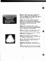
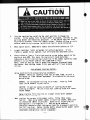
ALWAYS turn the engine off and allow it to
cool before refueling. Do not smoke while
refueling.
DO NOT fill fuel tank completely. Fuel
will expand and run over. Wipe up spilled
fuel; clean up spills with detergent and water
before starting the engine.
A
ALWAYS keep a fire extinguisher handy.
CAUTION
h ~ Pressure cooling system.
. . Remove cap slowly.
. + .
'lIIo..
65098'
DO NOT allow trash to build up on the sprayer.
NEVER remove radiator cap until engine has
cooled .
ALWAYS keep all shields in place.
KEEP CLEAR of all moving parts and keep others
away when operating.
DO NOT wear loose fitting clothing that may be
blown or drawn into moving parts.
ACAUTION
SHIELDS ARE FOR
YOUR PROTECTION.
KEEP THEM IN
PLACE.
65DB51
ALWAYS turn off engine and apply brakes before
checking, adjusting, repairing, lubricating,
or cleaning any part of the sprayer.
CAUTION: Use caution when working with hydraulic
fluid under pressure. Escaping hydraulic fluid
under pressure can have sufficient force to
penetrate your skin, causing serious injury.
This fluid may also be hot enough to burn.
- 6 -
•
NEVER allow chemicals to come in contact with
the skin or eyes. Always wear protective
clothing recommended by the chemical manufacturer.
Never pour chemicals into an empty tank; fill
tank 1/2 full of water first.
ALWAYS dispose of empty chemical containers
properly. Be sure to follow the chemical
manufacturer's instructions for mixing chemicals.
Always wash spilled chemicals or spray residue
from sprayer to prevent corrosion and
deterioration.
ALWAYS select a safe area to fill, flush,
calibrate and clean sprayer where the chemicals
will not drift or run off to contaminate people,
animals, vegetation, or water supply.
NEVER place nozzle tips or other parts to one's
lips in an attempt to unclog the spray tip.
\
DO NOT spray when wind is in excess of chemical
manufacturer's recommendation.
ALWAYS store pesticides in their original
containers with label intact. Store pesticides
in a separate, locked bUilding.
USE the flashing warning lights when traveling
on public roads, day or night, unless prohibited by local law.
MAKE SURE the SHV emblem is in place and
visible from the rear when traveling on public
roads.
PLEASE refer to Page 39 for towing instructions
if it ever becomes necessary to to~ the sprayer.
('
- 7 L--
_
SPRAYER IDENTIFICATION
Each Hagie sprayer is identified by means of a frame serial number.
This serial number denotes the model, year in which it was built and the
number of the sprayer.
For further identification, the engine has a serial
number, the hydrostatic pump has a serial number, the wheel motors have
rer.
identification tags, and the planetary hubs have identification plates that
describe the type of mount and gear ratio.
To insure prompt, efficient
service when ordering parts or requesting service repairs from Hagie
Is.
Manufacturing Company, record the serial and identification numbers in the
space provided below.
Note:
s
e,
Reference to left hand and right hand used throughout this manual
refers to the position when seated in the operator's seat facing
forward.
s
SERIAL NUMBERS
SPRAYER
s
NOTE:
Serial number stamped in the
frame on right rear corner
s
r.
Di esel :
- 8 -
_
PLANETARY HUB IDENTIFICATION NUMBERS
Front,
Rear
HYDROSTATIC PUMP SERIAL NUMBER
FRONT WHEEL MOTOR MODEL NUMBERS
REAR WHEEL MOTOR MODEL NUMBERS
- 9 -
_
_
TEM
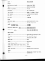
SPECIFICATIONS
nine
Manufacturer and mode1 ...•.....•............. Cummins Model 685.9
Type .............•...............•........... Natura11y aspirated
Number of cy1 inders
Six {6}
Horsepower .••....•.•.....•.................•. 120, i ntermi ttent
Type of fue1 .•.............................•. Number 1 or Number 2 diesel
Fuel system
Fi1tered, direct-injected
Slow idle •...•.•...........................•. 800 RPM
Fast idle ....•.....•.•...............•.•.•.•. 2,950 RPM
Drive
Hydrostatic pump
Sauer/Sundstrand 90 series
Range
Variab1e displacement
Speed - two-wheel drive ..................•••. 0-20 MPH
four-wheel drive .................•... 0-14 MPH
Hydrostatic wheel motor - rear ...•........••. Sauer/Sundstrand M35
front .•............. Sauer/Sundstrand M35
Final drives - rear ....•............•..•..•.. Torque-hubs W2B (28.22:1)
front
Torque-hubs W2B (13.30:1)
Basic Sprayer
Frame ..............................•.....•.•. Hydra-Hug with adjustable tread
C1earance ..........................•......... 72 inches (66" center)
Tread ..............................•......... Adjustab1 e 78" to 125"
Wheel base .........................•......... 106"
We ight ......•......••.......•......•......... 8800 pounds
Length (transom on1y} .•......••.......•...... 215"
Width w/booms folded w/122" tread setting .... 152"
Height ...•..........•.......•................ 134-1/2"
Ladder (two rear}
Mounted w/service platforms
Brakes
Type ..•.....•................................Mechanica11y actuated rear wheel,
caliper disc
- 10 -
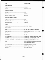
SPECIFICATIONS
Steering System
Type ..•......••........................•..... Hydrau1 i c
Control ...•....••.........•.............••••• Fu11-time power
Electrical System
Battery .•.....•.............................• 12V
Alternator ...••.....•............•.••.....•.• 105 AMP
Battery terminal ground ........•.....•••..••. Negative
Auxiliary Hydraulic System
Type ..........•...•...•...•.................. Open
Dua1 hydrau1 i c pumps ......................•.. Gear type
.~
Pressure setting ....•........................ 1850 PSI
Front & rear ..........•......... : ...........• 13.6 R 28 - 8 ply
Spray System
Boom ..................•...•...............•.• 60' dry type w/variab1e row spacing
Boom controls
Electro-hydrau1ic, fold - lift - level
Boom hose ....•.................•..........•.. 3/4 1.0.
11
Feeder hose .•..................•.........•... 1 1.0.
11
Solution tanks ...•.............•............. Two 400-ga1. polyethylene wjsight gauge
Optional
Two 400-gal. stainless steel wjsump
Agitation (both poly. & stain1ess) .........••Mechanical; hydraulically driven wj
variable speed control
Pump
Hypro centrifugal; hydraulically driven
wjvariable speed control
Solution valves ........................•...•. Electronic solenoid (145 H)
Pressure gauge .................•............. 100 PSI glycerin filled
Monitor ....................•...•......••...•• Raven 440 monitor
- 11 -
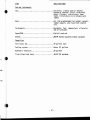
SPECIFICATIONS
Cab and instruments
Cab
: ...•...................•. Electronic climate control (R134a)
w/paper &charcoal filter, windshield
wiper, flashers, side mirrors~ dome
light, tinted glass & six halogen work
lights
Seat.
Air ride w/adjustment for height, weight,
lumbar support, and 3 position cushion
tilt
Instruments ....•............................. Hourmeter, fuel, temperature, alternator
and oil pressure
Speed/RPM ..........•...•.........•........... Digital read-out
Stereo .••............••.•..•...............•. AM/FM stereo cassette w/dua1 speakers
Capacities
Fuel tanks (2) •••..••..•.•................... 40 gallons each
Cooling system•........•..................... Seven (7) gallons
Hydraulic reservoir
20 gallons
Tires (front and rear)
18-22 PSI maximum
Ige
'en
- 12 -
II
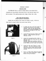
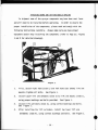
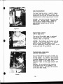
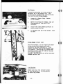
PREPARING TO OPERATE
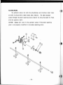
HYDRA-HUG FRAME
The HYDRA-HUG frame, an exclusive Hagie design, uses hydraulically
suspended and interconnected telescoping legs to help keep the booms level
when one wheel of the machine passes over a bump or drops into a hole.
WHEEL TREAD AND ROW SPACING
(Without hydraulic tread adjust)
Knowing the row spacing of the field one intends to spray, follow the
steps below to properly obtain the desired tread setting.
Figure 1
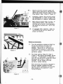
1.
To adjust the legs, park the sprayer on
level ground and shut off the engine.
CAUTION: Firmly set the parking brake
and to assure no possible movement, block
the wheels on the opposite side, both
front and rear.
2.
Loosen bolts and jam nuts (Items A and B;
Page 14). Remove the bolts and nuts
from the tie rod.
3.
Loosen the leg mounting bolts (refer to
Page 14) on both the front and rear legs on
one side only.
CAUTION: Loosen only enough to allow for
free movement of the leg on the main frame.
Do not remove the bolts under any condition.
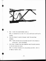
4.
Loosen the lock nuts (Figure 1) on the
leg brace. This will allow one or the
other leg to move further than the other
leg when adjusting to the desired tread
setting.
5.
Place a suitable block under the steering
arm or use a chain (outlined in Figure 2)
before raising the sprayer.
Figure 2
- 13 -~----------
I
t
Ii
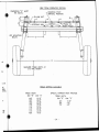
VIEW FROM OPERATOR STATION
DIMENSION "0" MUST
BE EQUAL
STEERING PIVOT
VERTICAL POSITION
•
ARM
LEG MOUNTING
BOLTS
1----
C
----·1
f----
C----;
E
:k
MEASURE TREAD WIDTH AT
1/2 TIRE HEIGHT
3;
s on
or
TREAD SETTING AVAILABLE
arne.
tion.
TREAD WIDTH
DIM "E"'
DIM" C"
r
ng
2)
124"
122"
120"
118"
116"
114"
112"
110"
108"
27.5"
26.5"
25.5"
24.5"
23.5"
22.5"
21.5"
20.5"
19.5"
SPECIAL NARROW ROW PACKAGE
TREAD WIDTH
DIM "t'
DIM" C"
90"
84"
78"
- 14 -
10.5"
7.5"
4.5"
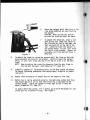
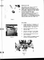
Figure 1
6.
Ra i se the sprayer until the tires nil I !til
side being adjusted are just touch 11111
the ground.
CAUTION: When raising the sprayer,
be sure the solution tanks are empty,
7.
To adjust the tread out, place a suit
able prying tool under the center of
the tire and pry out at the same timll
that you push out at the top of the
leg. Carefully lower the sprayer to
the ground which, in turn, will allow
the leg to slide outward. Repeat tho
procedure until the desired tread is
obtained.
8.
To adjust the tread in, raise the sprayer until the tires on the side
being adjusted are just off the ground. Carefully lower the sprayer
which, in turn, will allow the top of the leg to slide in on the main
frame.
NOTE: When adjusting the tread the dimension from the main frame to
the leg must be equal. (See Dimension "C n ; Page 14.)
9.
Carefully tighten all leg mounting bolts to 120-foot pounds of torque,
following tightening procedures that ensure equal torque on all mounting bolts.
10.
Repeat above procedures to adjust and set the opposite side legs.
11.
Before toe-in can be adjusted properly, the Hydro-Hug system must have
the proper amount of oil so that each front leg is adjusted to the
correct height. Check the sprayer's front legs to see if they are
equal (Dimension "0"; Page 14).
To adjust Hydro-Hug system, fill a grease gun with EP-90 weight oil and
attach gun tip to grease fitting. See Figure 1.
- 15 -
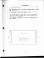
TOE-IN ADJUSTMENT
I.
Turn the steering wheel to position the center steering pivot straight
up and down (see Page 14).
~.
With suitable prying tool, align front tires with rear tires by sighting
down side of tire.
~.
Line up holes on tie rod next to steering pivot first (see Page 14).
Re-install bolts and nuts; tighten firmly.
4.
Turn inner tie rod next to jam nut "B" in or out to line up with the
nearest hole in the tie rod tube, then turn out one additional turn.
Tighten jam nut "B" (see Page 14).
5.
Line up holes by turning wheels.
tighten firmly.
Re-install tie rod bolts and nuts;
- - - - - - - - - - - - 12.3 1/2 - - - - - - - - - - - -
FRONT OF MACHINE
t
EXAMPLE OF CORRECT TOE IN
TOP VIEW OF FRONT TIRES
(MUST BE 1/2 TO 3/4 TOE IN)
f - - - - - - - - - - - - - - 124 - - - - - - - - - - - - -
- ·16 -
OPTIONAL
HYDRAULIC TREAD ADJUSTMENT
The hydraulic tread adjust is operated by a single switch located in
the R.H. console.
1.
CAUTION:
When adjusting the tread, make sure you adjust the legs all
the way to the end of the stroke of the cylinders, either going out
or coming in.
By this means you will maintain the proper toe in
setting.
2.
NEVER adjust the hydraulic tread on a public roadway.
Make sure
the sprayer is on level ground where there are no ditches or
valleys to interfere when you do the adjustment.
3.
ALWAYS adjust the tread between two and five MPH; it can be adjusted
going forward or you will find that sometimes it may adjust more
easily by backing up.
4.
Make sure you have enough room to adjust the legs when going either
forward or in reverse.
5.
When you adjust the hydraulic tread adjust you will notice a
squealing-type noise.
the relief setting.
This noise is the hydraulic system reaching
Do not be alarmed at this noise during the
adjustment.
6.
Make sure that the nylon strips on the tread adjustment brackets on
both the front and rear legs are lubricated during adjustment.
- 17 -
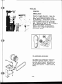
7.
The hydraulic tread adjustment bolts (Item 1) can be adjusted to
allow more or less clearance for the legs to slide on to the main
frame.
CAUTION:
Too much clearance will hinder in adjustment.
nUll WllStl£IIT ASSUIIl T
1IC1.
m
..n
2
1 J:lUSI
0
,,
5
m1l1
2 :151713
4 :151711
0 :15170
I
0
I
, ,
I
- 18 -
IICSC2IPT IGI
~
,
, ,
!
'M1 &
1
II
II
12
13
,
11
15
0
1
!100m
lamS
_7
IOG2U
4 tolIUl
,.110111
,UllllI
I
moDS
111010
MAD W U; IlSll; 1(U
l . 1ll(AD ADI U; IlSII:
mAD ADI IDI l£e MlI5t C11111£
mAD ~ JIIlI I£MIII: .!SST
mAD ID1 Slfili. %2 ~
MAD IIlJ til. [11 lIB:
'~1 I 1I:11Q.1
IJ2IIIIt 1 1 In IlO 1\1.1
I /2UIt 1 2 11:1 IQ. r
IJ2IIIIt 1 2 In 1£1 1\1.1
5 " . 1 ll1ltn Illl (;Ill
5,/8l111C 1£1 1111
I J2IIIIt ID STGVtI lIlT
5" rLAl USIf SA[
3,/8l111C 10 STGVtI lIlT
"
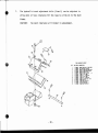
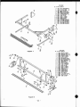
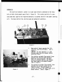
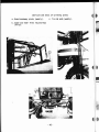
ATTACHING BOOMS AND SETTING NOZZLE SPACING
In shipment some of the sprayer components may have been sent loose
and will need to be installed before operating.
In order to ensure the
proper installation of the components, please read and comply with the
folloWing instructions carefully.
Always make sure you have proper
equipment and/or help installing the components (refer to Page 21; Figures
1 and 2 for detailed drawings).
Figure 1
1.
First, attach right hand (Item 1) and left hand (not shown) lift arm
mounts; tighten all bolts.
2.
See Figure 1.
Install upper lift arm we1dment (Item 2) to lift arm mounts (Item 1),
using proper bushings and bolts provided.
See Figure 1.
3.
Install lift cylinders (Item 3), using correct bushings and bolts.
See Figure 1.
4.
After installing the lift cylinders, install two lower lift arm
we1dments (Item 4), using correct bushings and bolts.
- 19 -
See Figure 1.
5.
Next - install the transom weldment (Item I).
NOTE:
An overhead hoist or fork lift is very useful when installing the
transom.
6.
After the transom is securely fastened, install the outer boom
weldments.
NOTE:
Tighten the boom spring using about one-half of the threads on
the eye bolt.
7.
Do not overtighten.
After Steps 1 through 6 have been completed, mount the nozzle spacings
to the outer booms and transom.
NOTE:
For further information for using bushings and bolts, refer to
to Page 21; Figures 1 and 2.
- 20 -
ltrl"'_'
ou.
OTT ',IU IIID. 1UCIt',1' IGIl
I ....n
I
I
II 'lOll'
I 110111
1
I
D
''''1$
~
•
,
$
I
7
,
,-1'1M"
I
'S '70111
I In511
II _ 3
I
10
11
II
13
I
'0
I
,
14
fCUl.l
"'1'10141
3<.
'I "'lllO
"1U7
I Imll
1$
II
I "$In
I 1""'0
I tUl"
I "$141
17
"
"
10
1_1Ir1 ....... _ _ 17
III L1r1 .... 11! U III
a
tH lltT ... 1ft .., 210
•
",-I.IF'_"
. . "In,. LCM 411
_IIC. C'Il
_ l l f l .... '0 2$'/21' U
M11 '-1M, .". LIn . . . .
1/_ IIfI RA.,U leac III!
ltrl cYI. Am
1/_ I I IV ""
, , - 1 I III 10 1111
1,tUIIC 1 3 '/l I(IIlllI
, _ I • lEI lOLl
.'lf5
"
$ ' - . ' STDYI:' ""
111111I'O ~ .m.tII' Will'
llrl II'/D 11K ASSY." W/lIJ
I!'!L 11I'O ' " 'SST. ~/2I'
lOlL "" , . .\SST. JI!Z1./lU
rQ 11I'O Tllll AlSY. ,. U.I/lIJ
rllla IITI , . A!SY.ODIU'AI.I
1I.1ISOII AS'St1a.,.
Figure 1
lin.
,
2
3
•$
nom
7
I
I
10
11
I
I
I
12
I
""
"
11
It
20
21
12
23
2'
IS
It
27
21
It
30
- 21
2 110150
I
I.
,_,
,,,
I
• 'TlIOJ
2
I
13
Figure 2
OTf 'U, NO. IlOeII,rICli
1I0H3
2 \tOm
2 'lam
,''''''
110471
110m
"0'"
•2 I"",
470111
•
IOOUI
•• '""'
l7100!
.
100131
• .,
I
2 100"'1
2
llAlIIIll
,,-
,,-
. . . PIVOT " . SIII5«l
PI. eDT 3/11 1 I IIIC
IIOlL "' ullm l1lIt 1:IIl 1lI{1b
lOCII.au.r ..DltlIO
JM'",C'l'l waD tS.4O
III
lft rill. Ol\ VI , . 1540
'Q ell VI ""
"'"' ' " IIIlI 11III<1 "'0 ttl.O
loo C'Il """ 11II1 .. 0 I.SIO
lOlL WI 1* _ " 1$40 11
~WI l*Q. .... IS«!
11
I!'.
" _ ... no
n
"""l'rI AIIlllJlO 17O
l/l111l: I I '" [Y[ lOll
1/'211 Illlll(lS( lnf(
l/ltIII: I 1 3/' KI lOll
~_I~1I[11llI.1
~_ I ~ III lEI llI.l
~ 1/l1E1 llI. I
, _ I 3 3/' IV la.I
5_ I
'/lIIIl:
1tI ..,
• "80&
,/41.01I:
SlIMI ""
,
_ ID SIMI
IU1
•I "40'"
5
5" _
fl.AI""_ "MI
SAl '""
2 mIl5l
2 1ZmJ'
tit Am .'11$ " 1l!$11 UI
l[Y!.L en ,,"Y'. 2 J: 10
I~
• "
'/Ntfe
I
I
•
-...._.
1/l111l:II[ISIM.IIIlI
1/NOt I 2 '1l1E1 .... 1
I 3 • • •,
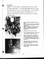
OPERATING THE ENGINE
PRE-OPERATING CHECKS
1.
2.
Check engine oil level. Do not operate engine when oil is below the
low mark on dipstick. See Page 43 for oil specifications .
•
Check the coolant level. It must be visible in the make-up tank. See
Page 43.
3.
Check the hydraulic oil level.
4.
Check air intake screens.
5.
Check for any oil or fuel leaks and correct if needed.
See Page 48 for specification.
See Page 43 for service and maintenance.
STARTING THE ENGINE
CAUTION: Start the engine from the operator's seat only. When running.the
engine in a building, be sure there is plenty of ventilation.
•
1.
Position hydrostatic control level in N (neutral) position.
2.
Set parking brake.
3.
Start the engine with the throttle at one-half speed.
4.
Turn key to the on position to check instruments .
- 22 -
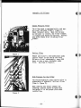
HYDROSTATIC SYSTEM
Pressure Port
Flow Check Port For Front Pump
The Series 90 pump is designed with a sequenced pressure limiting system
and high pressure relief valves.
When the pre-set pressure is reached, the
pressure limiter system acts to rapidly de-stroke the pump in order to limit
the system pressure.
Charge Pressure
To check out the closed loop system (the heavy duty variable displacement pump), install a 500 PSI pressure gauge at the charge pressure gauge
port.
See Figure 1. Start the engine and open the throttle to full RPM.
The charge pressure should be 320 to 350 PSI when equipped with the loop
flushing valve.
If it is below the required pressure, contact our Service
Department.
- 25 -
loop Flushing Valve
The loop flushing valve is used to remove
fluid from the main hydraulic circuit for
additional cooling and to remove additional
contamination in the high pressure circuit.
CAUTION: The loop flushing valve has been
factory set. Do not adjust. Damage to
the system may result if adjustment is
made without contacting our Service
Department .
. Figure 1
Displacement Limiters
(IOO cc pump only)
The series 90 variable pump is equipped
with mechanical displacement (stroke)
limiters (Item 1; Figure 2).
CAUTION: The limiters are factory set and
require no further adjustment. If adjustments are made without contacting our
Service Department, damage may result to the
system and void all warranties .
. Figure 2
Traction Valve (rear only)
(Optional attachment)
This system reduces spin-out if muddy conditions prevail or if wheels lose traction
for any reason. The valve is activated by
a switch located on the right hand console.
When this valve is activated, a red
indicator light on the gauge console will
show.
Caution: Do not activate the traction
valve above seven MPH or damage to the
system may result. Activate the traction
valve only when needed.
Figure 3
- 26 -
HYDRAULICS
The auxiliary hydraulic system is an open type directly connected to the heavy
duty variable displacement pump (Item 1; Figure 2). This system consists of a geartype pump that supplies the required hydraulics to operate the full time power steering
unit.
The boom controls the solution pump and mechanical agitation.
L
. Figu.re 1
.Figure 2
1.
Boom control levers operate the lift,
leveling, and fold cylinders. Item 1;
Figure l.
CAUTION: Be sure everyone is a safe
distance away from the sprayer before
operating levers.
2.
The solution variable flow control lever
operates the solution pump hydraulic
motor for spray pressure. The more
solution pressure desired, the further
the lever needs to be moved forward.
Item 2; Figure 1.
3.
The agitation variable flow control lever
operates the hydraulic motor for the
required speed. The more speed required, the farther the lever needs to be
moved forward. Item 3; Figure 1.
- 27 -
AIR CONDITIONER
The cab is equipped with an R-134a air conditioning system.
CAUTION:
"ing
When recharging the air conditioning, be sure to check the air
compressor to see if it is an R-12 or R-134a system and charge accordingly.
Do not mistake refrigerants
L-.
DO NOT MIX REFRIGERANTS
:....----J
If an R-134a air conditioner system
is mistakenly charged with R-12,
serious problems, such as compressor
seizure, can result. Therefore, confirm
before charging with refrigerants.
The air conditioning system is equipped with an electronic climate
control system that monitors the heating, air conditioning and dehumidification.
The control has a wide range temperature selection of 60F-90F
(or 15C-32C).
To select the desired temperature, press the up or down
switch until you reach the desired setting.
<I
- 28 -
1.
The fan speed has an eight position selection to control the amount
of air flow out of the blower system
2.
Vent knob (Item 1) - this knob can be adjusted to control the amount
of outside air needed for proper ventilation.
4.
CAUTION:
To prevent air conditioner compressor damage and condenser
freezing, inside and/or outside, air intake vents must be open.
5.
Filter cleaning:
remove the two upper thumb screws, drop the door
down and remove the paper filter.
Clean by using air pressure or re-
place as needed.
For charcoal filters, remove and replace when chemical odor comes into
the cab through the filter.
- 29 -
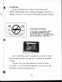
TACHOMETER
The tachometer is a programmable unit with a digital read-out
indicating RPM or MPH.
(The parameters have been set at the factory.)
Turn the ignition key to the on position. The display will show 0000
which indicates RPM.
Press in the button under MPH; the display will show
00.0 which indicates MPH.
To check the parameter settings, press in the desired button and hold
until four 8's (8888) are shown, then release.
The parameter setting will
be displayed for four seconds.
Parameter setting
RPM - diesel engine 357.
MPH - the Model 284 with 13.6R X 28 tires
should be 271.
To change or re-enter the parameters,
press in the desired button and hold in
until the four 8's (8888) are displayed.
Release the button and the parameter
setting will appear. If you want to
increase, press in the RPM button. To
decrease, press in the MPH button.
Programming MPH (Model 284 Sprayer)
To program the MPH, use the following
formula: example: 168 divided by (rear
tire) static load radius 23.6 X (rear)
Torque-Hub reduction 28.22:1 X 11
(speedometer pick-up plate) = 2209.8
divided into 600,000 = parameter setting
of 271.5.
This parameter setting should be checked
when you receive your sprayer. See
section under calibration.
- 30 -
Air Suspended Seat
Adjustable lumbar support
Back angle adjustment control
Manual air valve for height/
Seat cushion tilt
~
3-position, independently~
adjustable
5" Fore and aft adjustment
Ride firmness control knob
To acquire a more firm ride, adjust the
control knob in. For a less firm ride,
adjust the knob out.
Emergency Exit
The right window in the cab is removable
in the event that an emergency exit is
required.
To remove the side window:
A.
Grasp and pull the nylon ring next
to the emergency exit decal to remove the extrusion cord.
B.
Push window outward until clear of
window opening.
- 31 -
SOLUTION TANKS
The Model 284 can come equipped with either two 400-gallon polyethylene
or stainless steel tanks with mechanical agitation.
The stainless steel
tanks are held in place with mounting bolts and springs. Tighten only
enough to start to compress the springs.
STRAINER
The strainer in the top of each tank (Item 2) should always be in place
to catch debris or objects from falling into the tank when the tank lid is
removed.
•
- 32 -
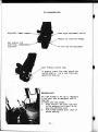
AGITATOR MOTORS
The agitator motors for both the polyethylene and stainless steel tanks
are held in place with a motor mount yoke (Item 3).
The yoke tap must
extend through the motor mounting plate (Item 4) to allow the motor to float
with the agitator shaft.
CAUTION:
Damage will occur to the agitator system if the motor mounting
yoke is not properly installed in the motor mounting plate.
~-
®
. '",
~ ~
3
V
'~
•
•
/
Q
'O,'C(@
~
~
n
~
- 33 -
'QD
SPRAY SYSTEM
IMPORTANT:
The solution pump is a centrifugal hydraulically driven pump
with variable speed control.
The solution pump assembly consists of a make-
up tank and check valve to aid in a self-priming system.
To aid in priming,
always fill the tanks through the bottom fill plumbing (Figure 1). To
operate the spray system in an efficient way and prolong its life, follow
these steps closely:
1.
Check contents and Quantity in spray
tanks.
CAUTION: Never attempt to operate the
spray system with no solution in the
spray tanks.
WARNING: Operating the spray system
with no solution in the tanks will
cause severe damage and void all
warranties.
2.
Completely open the tank valves.
3.
Start engine and maintain a relatively
slow engine RPM setting (1,000).
4.
Turn on main solution valve switch
(Item 1; Figure 2). At this time
the green spray control light, which
is located in the gauge console, will
be on, indicating the solution pump is
operating.
5.
Place individual solution valve
switches to the "on" position (Page
35; Item 1; Figure 1).
6.
Slowly move the hydrostatic control
lever forward to obtain the desired
ground speed.
_ _ _ _ _'---o--ll'':.-
Figure 1
Figure 2
- 34 - .
~
Figure 1
7.
Observe solution pressure gauge and
adjust spray pressure to the desired
setting by using solution pump variable
flow control lever (Item 2; Figure 3).
8.
Frequently observe the pressure gauge
and speedometer in order to apply the
desired amount of chemical determined.
9.
When pressure gauge drops to zero, or
spray pattern quits, shut off main
solution valve switch, solution pump,
and agitation system until refilling
sol ut ion.
10.
If equipped with a monitor, refer to
installation and service manual for
proper calibration.
Mechanical Agitation:
11.
Turn the agitation system on slowly by
moving the agitator variable flow
control lever (Item 3; Figure 3).
WARNING: Operation of the agitation
system with no solution in the spray
tanks will void all warranties on the
agitation system.
12.
The gland packing (Page 33; Item 1;
Figure 1) may require adjustment during
start-up. If adjustment is required,
shut off the agitation system and adjust
the gland nut (Item 2; Figure 1).
CAUTION: Do not adjust with the
agitation system running.
Figure 2
~
'- $
~
~
t
...
When replacing the packing, be sure to
wrap the packing clockwise on the
agitator shaft (reference to direction
when seated in the operator's seat
faci ng forward).
~-~
.Figure 3
- 35 -
<t
( ~
CALIBRATION
It is important to apply chemicals as recommended by the manufacturers of
the chemical products.
In order to do so, one must calibrate the sprayer using
the steps outlined below.
Determine the speed at which the sprayer will be driven while applying
chemicals.
To select the best speed, consider the lay of the land, the
condition of the soil, the type of crops, the height of the crops, etc.
Select the nozzle spacing (distance between each nozzle on the spray boom)
best suited for the intended spraying job.
NOTE:
For help in determining the nozzle spacing and height of boom,
refer to the spray product catalog that accompanies this manual.
There are several types and sizes of nozzles.
Select and install the type
and size of nozzles that are best for the intended spraying job and for the
(
speed that one intends to travel while spraying. The type and size of nozzles
selected will depend upon the speed the sprayer will travel, the nozzle spacing,
and the number of gallons that one intends to apply per acre.
NOTE:
When selecting the type and size of nozzles, refer to the spray
product catalog.
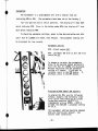
EXAMPLE:
Assume that one intends to spray at five MPH with 30-inch nozzle
spacing, using flat spray nozzles for broadcasting a herbicide, at the rate
of 10 gallons per acre.
calibration tube.
In order to select the best nozzles, use the Hagie
Select a chart near the bottom of the tube by using "tip
(nozzle) spacing" and "miles per hour".
Using 30-inch spacing at five MPH, the
corresponding number (.251) on that chart is the "flow rate".
The flow rate is
the amount of liquid that is applied from one nozzle in one minute, measured in
thousandths of a gallon (based on a rate of 10 gallons per acre).
Use a chart in a spray products catalog that covers flat spraying nozzles
(tips).
Read down the column in the catalog marked capacity 1 - nozzle (GPM)
- 36 -
until the number .25 is found or the number closest to it.
Then read left to
the column marked tip number; this will give you the nozzle (tip) number having
a delivery rate within the desired spraying pressure.
NOTE:
Check with the chemical manufacturer on recommended spray pressure.
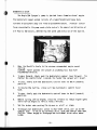
Test and calibrate (measure the actual flow rate) the spray system.
Fill the solution tank with clean water.
DO NOT ADD CHEMICALS UNTIL
CALIBRATION IS COMPLETED.
Apply the brakes, start the engine of the sprayer, and remain parked.
on the main, right, center, and left solution switches.
-~.
Turn
Move the solution
pump's variable flow control lever until the pressure gauge reads the desired
pressure for the above example.
Make sure that there are no leaks and that all nozzles are spraying a
desirable pattern.
Continue spraying in the stationary position for at least 10
minutes for proper warm-up of the sprayer and its system.
Use the calibration tube to catch one
nozzle's spray for one minute. (If the
flow rate is more than the tube will
hold, catch the spray in a larger container and then pour it into the tube. For
the example given above, a larger container
will have to be used.)
The numbered marks on the side of the calibration tube show the flow rate. The
measured flow rate should be the same as
the flow rate shown on the chart near the
bottom of the calibration tube - .251.
If the,measure flow rate is not the same as that on the calibration tube's
chart, move the solution pump's variable flow control lever to increase or
decrease (as required) the pump's pressure.
measure the flow rate.
Use the calibration tube and again
Continue adjusting the variable flow control lever and
continue measuring the flow rate until the proper flow rate is reached.
At this
time note the exact pressure gauge reading and maintain this pressure setting
while spraying in the field.
- 37 -
until the number .25 is found or the number closest to it.
Then read left to
(
the column marked tip number; this will give you the nozzle (tip) number having
a delivery rate within the desired spraying pressure.
NOTE:
Check with the chemical manufacturer on recommended spray pressure.
Test and calibrate (measure the actual flow rate) the spray system.
Fill the solution tank with clean water.
DO NOT ADD CHEMICALS UNTIL
CALIBRATION IS COMPLETED.
Apply the brakes, start the engine of the sprayer, and remain parked.
on the main, right, center, and left solution switches.
-~
Turn
Move the solution
pump's variable flow control lever until the pressure gauge reads the desired
pressure for the above example.
Make sure that there are no leaks and that all nozzles are spraying a
desirable pattern.
Continue spraying in the stationary position for at least 10
minutes for proper warm-up of the sprayer and its system.
-
~
Use the calibration tube to catch one
nozzle's spray for one minute. (If the
flow rate is more than the tube will
hold, catch the spray in a larger container and then pour it into the tube. For
the example given above, a larger container
will have to be used.)
~
The numbered marks on the side of the calibration tube show the flow rate. The
measured flow rate should be the same as
the flow rate shown on the chart near the
bottom of the calibration tube - .251.
If the,measure flow rate is not the same as that on the calibration tube's
chart, move the solution pump's variable flow control lever to increase or
decrease (as required) the pump's pressure.
measure the flow rate.
Use the calibration tube and again
Continue adjusting the variable flow control lever and
continue measuring the flow rate until the proper flow rate is reached.
At this
time note the exact pressure gauge reading and maintain this pressure setting
while spraying in the field.
- 37 -
«
("
All nozzles should be spraying at about the same flow rate.
~!~
If one drives the sprayer at the proper speed and maintains the right
pressure setting while spraying, the desired gallons per acre will be applied.
- 38 -
TRANSPORTING
A.
Driving
When driving the sprayer on a public road or highway, drive carefully
and follow these steps:
1.
Fold the booms in and tie them to the sprayer.
2.
CAUTION: Flashing hazard warning lights have been placed on the sprayer
to warn other drivers.
3.
A SMV (Slow Moving Vehicle) emblem has been mounted on the sprayer
to warn other drivers that one is moving slowly. Keep it properly
displayed!
4.
Know and obey all state laws for driving farm equipment on a public
road or highway.
5.
Adjust the sprayer's speed to suit the conditions.
6.
Slow down and use turn signals before turning.
7.
Keep a proper lookout, and maintain control of the sprayer.
8.
Do not drive under trees) bridges, wires, or other obstructions unless
there is clearance.
9.
Use extra care before entering or leaving a public road or highway.
- 39 -
(
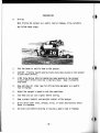
B.
Trailer
When moving the sprayer onto a trailer, follow these steps completely:
WARNING:
Never load or unload a sprayer with solution in the tanks.
~
--~-
--
~~~r."'~~~ ~
r::
-~~:,
J
(
1.
Be sure to read and understand the trailer's owner and operator manual.
2.
Hitch the trailer to the pulling vehicle as shown in the trailer's owner
and operator manual.
3.
Loading:
NOTE:
Extra care should be taken when loading the sprayer onto any
trailer. Consider whether it is best to back the sprayer on or
drive forward onto the trailer.
a. Pull the trailer to flat ground. Apply the pulling vehicle parking
brake and turn off the engine. Use tire blocks to keep trailer from
moving.
b. Fold in the sprayer's booms and tie them to the sprayer.
c. The loaded height and width of the trailer must conform to the law
of the state in which it is being used.
d. Lower the trailer ramps and set the ramp spacing for the sprayer's
tread setting.
e. Get someone to help guide onto the trailer.
at a safe distance from the sprayer.
Keep this individual
f. WARNING: Stopping the sprayer on the trailer loading ramps may result
in sprayer tip-over.
- 40 -
,e
g. Allow enough room between the sprayer and the pulling vehicle for
turning.
h. Secure the sprayer to the trailer. See the trailer's owner and operator
manual for instructions.
i. Cover or remove the SMV (Slow Moving Vehicle) emblem when traveling
over 25 miles per hour.
4.
When unloading the sprayer from the trailer, follow these steps:
a. Park the trailer on level ground for unloading.
b. Place in gear or park and turn off engine in pulling vehicle. Apply
parking brake and use tire blocks to keep the trailer from moving.
c. Lower the trailer ramps and set ramp spacing for the sprayer's tread
setting.
d. Release securing chains carefully.
e. Get help to guide off the trailer.
from the sprayer.
Keep everyone at a safe distance
f. Uncover or replace the SMV (Slow Moving Vehicle) emblem.
c
~
--~ -_::-=:~~. ~
~r~--l.
"-
l:':
--, I
,.
~..,.
~
(I
- 41 -
,
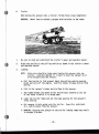
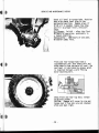
c.
Towing
It is not recommended that the sprayer be towed, but if-it should ever be
necessary, follow these steps carefully.
,
! ( tllll~!t .;
Figure 1
:
Figure 2
1.
Fold the booms in and tie them to the sprayer.
2.
Disengage the torque hubs by removing two outer cap bolts, turning
the outer cap with the extended center in toward the hub and reinstalling the two outer cap bolts. This process pushes on a springloaded splined shaft, disengaging the torque hubs ( Figure 1).
WARNING: Wheel motors will be ruined if these steps are not taken.
CAUTION: When re-engaging the torque hubs, make sure the springloaded spline shaft has returned to its extended position.
3.
Turn on the flashing hazard warning lights.
4.
Check to be sure the SHV emblem is in place and visible from the
rear (Figure 2).
5.
When towing, it is necessary that two vehicles of sufficient size
and weight for adequate pulling and braking ability are used. One
of these vehicles is used for pulling the sprayer; the second
vehicle for braking if the sprayer starts to overtake the towing
vehicle, such as going downhill. The reason for this is the sprayer,
once the torque hubs have been disengaged, has no braking power of
its own. Use extreme caution.
WARNING: Take steps to ensure that the items used between the towing
vehicle and braking vehicle (chain, etc.) are safely secured to prevent them from disconnecting.
6.
CAUTION: Excessive speed may cause damage to the torque hubs as well
as the hydrostatic system.
7.
Always reduce towing speed well in advance of any anticipated turns.
8.
Know and obey the state laws for towing farm equipment on public
roads and highways.
- 42 -
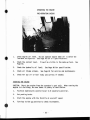
SERVICE AND MAINTENANCE
Perform these services every 10 hours or as required - whenever unusually
severe or dusty operating conditions prevail.
- ----'
~~~~
~:,_.~
OIL LEVEL - Diesel (check daily)
I
----
-
Never operate the engine with the oil
level below the "l" (low) mark or above
the "H" (high) mark. Wait at least 5
minutes after shutting off the engine
to check the oil. This allows time for
the oil to drain to the oil pan.
NOTE: The engine must be level when
checking the oil level to make sure the
measurement is correct.
Low Mark to High Mark Capacity:
6 cylinder - 1.89 liter (2.0 U.S. Quarts)
Refer to Engine Operation and Maintenance
manual for maintenance schedule.
Oil capacity of pan - 15 quarts.
t
Inspect and clean air intake screens,
radiator core, oil cooler and air conditioner condenser.
.
CAUTION: Failure to keep the air
intake system clean can cause overheating and damage to the hydrostatic system
and the engine.
--:-...:
E!
COOLANT
Check radiator coolant level and add if
necessary. A mixture of 50-50 water and
permanent type anti-freeze is recommended.
Itt
- 43 -
DRIVE BELT
Inspection
....
\.
!\.
-
CUl1I1lins diesel
-
...
~
.
,
.1~~Mi_"~'
"~>!~' -.
f.r.... _
~
l
I
i!J
!H~~
!HQ.:.
5:l
fA
-
If'
\'
'"
-A",'
tIC·
L--/-
.
Visually inspect the belt. Check the
belt for intersecting cracks. Transverse (across the belt Width) cracks
are acceptable. Longitudinal (direction
of belt length) cracks that intersect
with transverse cracks are not acceptable. Replace the belt if it is frayed or
has pieces of material missing.
Refer to Adjustment and Replacement
(Section 10) in Engine Operation and
Maintenance manual.
/1
Air conditioner drive belt
To tighten air conditioner compressor
drive belt (diesel engine), loosen
mounting bolts (Item 1) and adjust tbe
two (2) adjusting bolts (Item 2) for
proper belt tension. Tighten mounting
bolts.
- 44 -
Lubricate and check all pivoting points
a. Boom breakaway pivots (weekly).
c. Tie rod ends (weekly).
b. Upper and lower front leg bearings
(Daily).
II
\-.-
L
.""
II :(
- 45 -
t
SERVICE AND MAINTENANCE CHECKS
f
,
..............:-
i
~
Check oil level in torque hubs. Position
hubs with check level plug in the
horizontal position. Remove plug; if
EP-90 oil is needed, remove top plug
and fill to proper level; reinstall
plugs.
Oil change: Initial - after the first
50 hours of operation, preferably in
a loaded condition.
Subsequently - 1000 hours or one year,
whichever comes first.
•
i .,".:;,.
t~
~i~.l ~~~
~';<.-.'''~
-'=<.E~~.
4- It
Front and rear torque hubs have a
supplementary seal that keeps dirt and
other debris from the main oil seal. The
seal boot is lubricated by grease which
is injected through a zerk fitting
motor mounting bolt.
Check front and rear lug nuts; torque
to 8S-foot pounds.
CAUTION: Damage will occur to rim and
torque hub if lug nuts are not checked
often and kept tight.
- 46 -
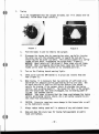
Air Cleaner
A properly maintained air inlet system is
necessary for a long engine life. Your
sprayer may be equipped with a filter minder
(see section under Filter Minder).
e
@.
0 .....
o
•II
1.
Loosen air cleaner clamp.
filter element.
Remove
2.
Before installing the element, wipe all
foreign material from the filter
container.
3.
Install the clean element carefully to
ensure proper sealing.
4.
If equipped with the filter minder, reset
to zero.
Filter Minder (diesel only)
The filter minder is an air restriction monitoring system that progressively and
constantly indicates how much air filter
capacity has been used and how element capacity remains. Service the air cleaner when
the filter minder reads 20" (80% of average
dirt holding capacity).
CAUTION: Service before the yellow indicator
reaches the red line.
t
• •
Line Strainer
Remove and clean line strainer screen.
Be sure the gasket is in place before
re-installing screen.
t
- 47 -
Ilt
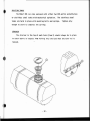
Hydraulic Oil Tank
~~-
.'.
.,,~~~
\
~
o
•
,/
7,:' ~
·r~.<.
Check hydraulic oil level in reservoir
and add if necessary (Figure 1).
Premium hydraulic fluids containing high
quality rust, oxidation and foam inhibitor
are required. Hydraulic oil must conform
to one of the following types:
anti-wear hydraulic oil, type F
automatic transmission fluid, or agricultural hydraulic transmission fluid.
Replace the oil in the hydraulic reservoir
every 500 hours or at the beginning of each
spraying season, which ever comes first.
.
Figure 1
Daily Checks
Figure 2
1.
Inspect and clean, if necessary, all
battery connections if corrosion is
present and check tension of battery
hold-down bracket. See Figure 2.
2.
Check leg mounting bolts; be sure
they are tight.
3.
Check the steering tie rod linkage;
be sure it is tight. See Figure 3.
4.
Check parking brake tension and adjust if necessary.
5.
Check to maintain an adequate neutral
setting of the hydrostatic pump.
-'-:.-
~
.
.!
1
(
~!::~~
Figure 3
- 48 -
I
Hydraulic Oil Filters
tH
Charge Pressure Filter
The filter head is equipped with a red popup visual indicator (Item 1; Figure 1).
Check indicator daily. When the red popup indicator is visible, the filter element
is clogging and should be replaced. Replace
only with a Beta 10 of 14 rating filter
. element .
-~
...;'
""
- - - -,... -
Figure 1
Suction Filter
Remove and install a new hydrostatic pump
suction filter at the end of the first
50 hours of use; subsequently, every 250
hours or once a year, whichever comes
first. See Item 2; Figure 1.
e
High Pressure In-Line Filter
The electro-hydraulic boom control valve is
protected by a hydraulic nin-line n filter
(Item 1; Figure 2).
When removing the filter element for
cleaning, caution should be taken that
the gasket is in the proper place when
reinstalling.
Figure 2
e
- 49 -
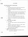
STORAGE
A.
Preparing the sprayer for storage.
1.
Drain the coolant from the engine and radiator.
Probe the drain
holes during draining to ensure they are not clogged by sludge,
scale, or other deposits.
Fill the cooling system to the top with
a 50-50 water/anti-freeze mixture.
Run engine to operating
temperature and re-check level.
NOTE:
If anti-freeze is added, make sure the engine is run to
operating temperature to assure proper mixing of solution.
2.
Add a fuel stabilizer to the fuel and fill fuel tank.
3.
Run the engine until it is at operating temperature, then drain
the engine oil.
Refill with new engine oil and install a new
lubricating oil filter element.
4.
Run the engine until it reaches normal operating temperature.
Cycle all hydraulic functions including the steering.
5.
Release tension on all belts.
For more detailed information, see the engine manufacturer's
handbook.
6.
Use plastic bags and water resistant adhesive tape to seal the air
intake opening, the exhaust manifold orifice, and the air vent on
the fuel tank.
7.
Disconnect and remove battery or batteries.
charge the battery.
Completely clean and
Coat the terminals with petroleum jelly and
store battery in cool, dry place.
8.
Thoroughly clean the sprayer.
Touch up any painted surfaces that
are scratched or chipped.
9.
Replace worn decals.
Contact Hagie Manufacturing Company, Box
273, Clarion, Iowa 50525, for replacement decals.
- 50 -
10.
Use a multi-purpose grease to coat exposed hydraulic cylinder
rods.
11. To winterize the .spray system, use a pre-mixed solution of 50-50
permanent type anti-freeze and water.
Run this mixture through
the spray system until it comes out all boom openings.
12.
Use a plastic bag and water resistant adhesive tape to seal the
engine oil filler cap and the hydraulic oil tank breather cap.
13.
If the sprayer must be stored outside, cover it with a waterproof
cover.
B.
Removing the sprayer from storage.
1.
Check the condition and air pressure of all the tires.
Check the
section on specifications for proper pressure.
2.
Unseal all openings that were sealed in the storage procedures.
3.
Clean and install the battery.
Be sure to attach the battery
cables to proper terminals.
4.
Tighten all belts.
5.
Check levels of engine oil, hydraulic oil and engine coolant.
Add, if necessary.
Replace any worn belts.
Remember, a mixture of 50-50 anti-freeze and
water will cool adequately in summer as well as protect in winter.
6.
Completely clean the sprayer.
(NOTE:
Protective compounds such
as grease can harden under exposure to weather conditions.)
7.
Perform all needed services as instructed under Maintenance in the
Operator's Manual.
8.
For starting instructions, see section on Operating Information.
- 51 -
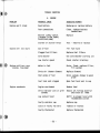
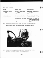
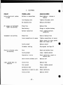
TROUBLE SHOOTING
A.
PROBLEM
PROBABLE CAUSE
SUGGESTED REMEDY
Engine won't crank
Dead battery
Recharge or replace battery
Poor connections
Clean, tighten battery
connections
Neutral safety switch
(Located in the Sauer/
Sundstrand pump)
Replace
Starter or starter relay
Test - rebuild or replace
Out of fuel
Fill fuel tank
Clogged fuel filters
Replace fuel filters
Cold weather
Use cold weather starting aid
Low starter speed
Check starter & battery
Water in fuel
Drain, flush, replace filter,
fill system
Dirty air cleaner element
Replace element
Poor grade of fuel
Drain system; change to good
grade
Fuel tank vent clogged
Open fuel tank vent in cap
Engine overloaded
Reduce load
Dirty radiator core or grill
screens
Remove all foreign material
and clean all items
Low coolant level
Refill to proper level with
recommended coolant
Faulty radiator cap
Replace cap
Loose or faulty fan belt
Tighten or replace
Faulty thermostat
Replace thermostat
Engine will not start
(B
ENGINE
Engine misfires; runs
uneven, low power
Engine overheats
~I Ct
- 52 -
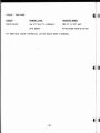
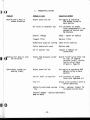
1
(Engine - Continued)
PROBLEM
PROBABLE CAUSE
SUGGESTED REMEDY
Engine knocks
Low oil level in crankcase
Add oil to full mark
Cold engine
Allow proper warm-up period
il(l
For additional engine information, see the engine owner's handbook.
(I
- 53 -
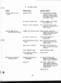
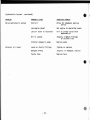
B.
(t
THE SPRAY SYSTEM
PROBLEM
PROBABLE CAUSE
SUGGESTED REMEDY
Solution pump will not
prime
Low water level
Fill solution tanks through
the bottom fill to aid in
priming. Solution pumps
are normally self-priming
after once filled
Air leak in suction line
Inspect; tighten all fittings
on suction line
Solution valves turned off
Turn solution valves to open
position, allowing air to
leave system
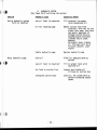
Solution pump not producing normal pressure
(t
Malfunction of electric
solution valve
Clogged line strainer screen Remove screen; clean thoroughly and replace screen;
tighten strainer cap to
avoid air leak
Air leak in suction line
Inspect and tighten all
connections
Restricted solution flow to
pump
Main solution tank shut-off
valve or valves not completely open
Suction hose collapsed
Obstruction at inlet end of
hose, causing high vacuum
on hose
Faulty hydraulic pump
Replace hydraulic pump
Faulty hydraulic motor on
solution pump
Replace motor
Internal restriction of
diaphragm
In case of a build-up of
chemical, disassemble; inspect; clean; reassemble
Electrical
Check fuse; check ground;clean contact terminals;
check continuity of wires;
check switches; short in
solenoid coil
Replace valve
- 54 -
(Spray System - continued)
let
PROBLEM
PROBABLE CAUSE
SUGGESTED REMEDY
E
No reading on pressure
gauge
Orifice in back of gauge
clogged
Remove gauge; clean orifice;
re-install
~
Faulty gauge
Replace gauge
Air leak in suction line
Inspect; tighten all fittings
in suction line
Loss of glycerin from gauge
Glycerin acts as a damper to
stabilize needle reading.
If it leaks out, replace
gauge
Erratic reading on
pressure gauge
-~.
NOTE:
If your unit is equipped with a mounter (see Figure 1), refer to the manufacturing service manual for probable problems and suggested remedies.
ICt
Figure 1
NOTE:
If your unit is equipped with a high pressure system, call our Service
Department for probable problems and suggested remedies.
- 55 -
(~
J
"
f' I(~t
C.
HYDROSTATIC SYSTEM
PROBLEM
PROBABLE CAUSE
SUGGESTED REMEDY
Machine won't move in
either direction
Engine speed too low
Set engine at operating
RPM before trying to
move machine
Oil level in reservoir low
Fill reservoir to proper
level w/approved oil; see
chapter on Service and
Maintenance
Control link.age
Check - repair or replace
Clogged filter
Replace filter
Hydrostatic pump not turning Check. drive coupling
.,
1L~~achine
I~'
will move in only
one direction
Hydrostatic system responding slowly
Faulty hydrostatic pump
Replace pump
Air in suction line
Inspect & tighten all
connections
Faulty high pressure relief
valve
Switch relief valves from side
to side. If problem
reverses itself, replace
faulty relief valve
(Figure 1; Page 47)
Engine speed too low
Set engine at operating RPM
before trying to move
machine
Low oil level in reservoir
Fill reservoir to proper
level with approved oil
Cold oil
Always allow system to warm up
before operating
Partially restricted suction
line
Filter - replace; inspect for
collapsed suction hose
Internal damage - replace hydrostatic
pump or motor
(t
- 56 -
(Hydrostatic System - continued)
(( I
PROBLEM
PROBABLE CAUSE
SUGGESTED REMEDY
Noisy hydrostatic system
Cold oil
Allow for adequate warm-up
period
Low engine speed
Set engine at operating speed
Low oil level in reservoir
Fill to proper level with
approved oil
Air in system
Inspect; tighten fittings
on suction line
Internal damage to pump
Replace pump
Loose or faulty fittings
Tighten or replace
Damaged O'Ring
Inspect; if damaged, replace
Faulty hose
Replace hose
External oil leaks
~, I
- 57 -
D. HYDRAULIC SYSTEM
(See Pages 25-27 outlining the system)
r(t
PROBLEM
PROBABLE CAUSE
SUGGESTED REMEDY
Entire hydraulic system
fails to function
low oil level in reservoir
Fill reservoir to proper
level w/approved oil
Oil not reaching pump
Remove suction hose from
reservoir; hold the far end
higher than pump; hand feed
two quarts approved oil
through suction hose by
bumpi~g engine w/starter
(careful not to start
engine).
Re-install hose; tighten
all fittings; pull up on
throttle control; start
engine
Faulty hydraulic pump
Replace hydraulic pump
Col d oil
Allow for adequate warm-up
period
Low oil level in reservoir
Fill to proper level with
approved oil
Air leak in suction line
Inspect and tighten all
fittings on suction hose
Collapsed suction hose
Cold oil; let system warm up
before increasing engine
speed
Noisy hydraulic pump
~)
;( t
t
- 58 -
E.
ELECTRICAL
PROBLEM
PROBABLE CAUSE
SUGGESTED REMEDY
Entire electrical system
is dead
Battery or connections
Check battery - charge or
replace
Low charging rate
Tighten alternator belt
No charging rate
Replace alternator
Blown fuse
Replace fuse
Dead battery
Charge or replace battery
Battery connection
Clean; tighten battery
connection
Blown fuse
Check & replace fuse
Loose connections at sensor
Tighten connections at sensor
All gauges on instrument
panel not working
Tachometer not working
Adjust sensor to clear speedometer disc about l/S"
Electric solution valve
not working
Light system does not
function
Faulty sensor
Replace sensor
Parameter setting
Re-program; see Page 30
Fuse
Check and replace fuse
Faulty ground
Clean; tighten ground
Separation in wire
Check continuity; repair or
replace wire
Short within solenoid coil
Repl ace coil
Faulty fuse
Replace fuse
Poor ground
Clean; tighten ground
Burned-out bulb
Replace bulb
Separation or short in wire
Check continuity
Faulty switch
Replace switch
- 59 -
,•
LIMITED WARRANTY
HAGlE MANUFACTURING COMPANY NEW EQUIPMENT WARRANTY
1.
The warranty.
a.
This warranty gives you specific legal rights, and you may also
have other rights which vary from state to state.
b.
Hagie makes this warranty only to the original purchaser of its new
equipment.
c.
The warranty period ends 12 months from the date of delivery of the
equipment to-~he original purchaser. When requesting warranty
service, the original purchaser must present evidence of the date
of delivery of the equipment.
d.
~
Parts or rebuilt assemblies furnished under the terms of this
warranty are not warranted beyond the original warranty period.
•
e.
Exceptions to this warranty must be covered by separate warranty
agreements.
2.
ITEMS NOT COVERED BY HAGlE WARRANTY
a.
Used equipment.
b.
Tires, tubes, engines and batteries (under separate manufacturer's
warranty).
c.
-lDepreciation or damage caused by normal wear, accident, improper
maintenance, improper storage, or improper use.
d.
Service calls and transporting the equipment to and from the place
where the warranty work is performed.
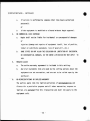
3.
UNAPPROVED SERVICE OR MODIFICATION
NOTICE:
•
All obligations of Hagie Manufacturing Company under this
warranty shall be terminated:
- 60 -
(Limited Warranty - continued)
a.
If service is performed by someone other than Hagie authorized
personnel;
or
b.
4.
If the equipment is modified or altered without Hagie approval.
NO COMMERCIAL lOSS COVERAGE
a.
Hagie shall not be liable for incidental or consequential damages
or
injuries (damage and repairs of equipment'itself, loss of profits,
rental or substitute equipment, loss of good will, etc.)
b.
SOME STATES DO NOT ALLOW THE EXCLUSION OR LIMITATION OF INCIDENTAL
OR CONSEQUENTIAL DAMAGES, SO THE ABOVE LIMITATION MAY NOT APPLY TO
YOU.
5.
MERGER CLAUSE
a.
The entire warranty agreement is included in this writing.
b.
Any oral statements that are made by the selling persons about the
equipment are not warranties, and are not to be relied upon by the
purchaser.
6.
NO REPRESENTATIONS OR IMPLIED WARRANTY
The parties agree that the implied warranties of merchantability and
fitness for a particular purpose and all other warranties, express or
implied, are excluded from this transaction and shall not apply to the
equipment sold.
~
- 61 -
- Z9 -
•
'faN~OH3H
•
- £9 -
to
VONWOH3H