1
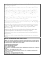
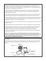
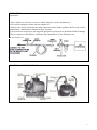
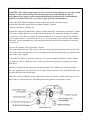
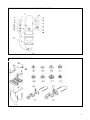
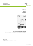
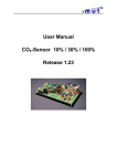
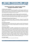
OPERATION MANUAL FOR
BRAKE FLUID EXCHANGER
PRODUCT AND COMPANY IDENTIFICATION
Product Name: Brake Fluid Exchanger GS-432
Product Use: Brake fluid exchanger
Date of issue : 27.05.2012
Revision Date : 05.09.2013
Company Information: Sudheimer Car Technik Vertriebs GmbH
Adress: Feldstrasse 154, 22880 Wedel, Germany
Information telephone : +49 (0) 4103 1211 118
Emergency telephone : +49 (0) 4103 1211 0
E-mail : [email protected]
Fax : +49 (0) 4103 1211 116
SPECIFICATIONS
Item
Description
Functions
Remove, and replace fluid from most types
and models of vehicle brake systems, Also
removes trapped air.
Working Air Pressure
10 to 40 PSI:Consumption:4.5CFM at 30PSI
Air Inlet
1/4”-male quick couple
Tank Fluid Capacity
1.32 Gallons(5.25 quarts)
Pressure Regulator
Manual control dial, locking
Pressure Gauges
0~140PSI,20PSI increments; within 20 PSI
increments, marked in 2 increment
Drain Tubes
2-12-1/2(L)×0.316(dia.) inches clear
polyurethane with rubber bleeder adapter tip
Brake Fluid Filler
Hose
10 feet, 3 inches (L) × 1/2 inch (dia.);
reinforced polyurethane with ball valve and
quick coupler at one end
Collection Bottles
2-9(H)×4-3/4(L) × 2-1/4(W) inches; 0.26
gallon (one quart)
Collection Bottles
2-9(H)×4-3/4(L) × 2-1/4(W) inches; 0.26
gallon (one quart)
1
Weight
19.6Lbs
Accessories
Master Cylinder Adapters kit:11-domestic
and import vehicle in plastic tool box .See
Parts List at the end of this manual for details
Save This Manual
You will need the manual for the safety warnings and precautions, assembly instructions,
operating and maintenance procedures, parts list and diagram, Keep your invoice with this manual.
Write the invoice number on the inside of the front cover. Keep the manual and invoice in a safe
and dry place for future reference.
SAFETY WARNINGS AND PRECAUTIONS
WARNING: When using tool, basic safety precautions should always be
followed to reduce the risk of personal injury and damage to equipment.
Read all instructions before using this tool!
1. Keep work area clean. Cluttered areas invite injuries.
2. Observe work area conditions. Do not use machines or power tools in damp or wet locations.
Don’t expose to rain. Keep work area well lighted. Do not use electrically powered tools in
the presence of flammable gases or liquids.
3. Keep children away. Children must never be allowed in the work area. Do not let them handle
machines, tools, or extension cords.
4. Store idle equipment. When not in use, tools must be stored in a dry location to inhibit rust.
Always lock up tools and keep out of reach of children.
5. Use the right tool for the job. Do not attempt to force a small tool or attachment to do the work of
a larger industrial tool. There are certain applications for which this tool was designed.
It will do the job better and more safely at the rate for which it was intended. Do not modify
this tool and do not use this tool for a purpose for which it was not intended.
6. Dress properly. Do not wear loose clothing or jewelry as they can be caught in moving parts.
Protective, electrically non-conductive clothes and non-skid footwear are recommended when
working.Wear restrictive hair covering to contain long hair.
7. Use eye and ear protection. Always wear ANSL approved impact safety goggles.
Wear an ANSI approved dust mask or respirator when working around chemical dusts and mists.
8. Do not overreach. Keep proper footing and balance at times. Do not reach over or across running
machines.
9. Maintain tools with care. Inspect tool cords and hoses periodically and, if damaged, have them
replaced, or repaired by an authorized technician. The handles must be kept clean, dry, and free
from oil and grease at all times.
10. Remove adjusting keys and wrenches. Check that keys and adjusting wrenches are removed
from the tool or machine work surface before operating.
2
11. Avoid unintentional starting. Be sure the air pressure is in the off position when not in use and
before making hose connections.
12. Stay alert. Watch what you are doing, use common sense. Do not operate any tool when you
are tired.
13. Check for damaged parts. Before using any tool, any part that appears damaged should be
carefully checked to determine that it will operate properly and perform its intended function.
Check for alignment and binding of moving parts; any broken parts or mounting fixtures; and
any other condition that may affect proper operation Any part that is damaged should be
properly repaired or replaced by a qualified technician. Do not use the tool if any control or
switch does operate properly.
14. Replacement parts and accessories. When servicing, use only identical replacement parts. Use
of any other parts will void the warranty. Only use accessories intended for use with this
tool. Approved accessories are available from Harbor Freight Tools.
15. Do not operate tool if under the influence of alcohol or drugs. Read warning labels if taking
prescription medicine to determine if your judgment or reflexes are impaired while taking drugs. If
there is any doubt, do not operate the tool.
16. Pacemaker safety warning. People with pacemakers should consult their physician(s) before
using this produce. Electromagnetic fields in close proximity to a heart pacemaker could cause
interference to, or failure of the pacemaker. In addition, people with pacemakers should
adhere to the following:
Caution is necessary when near the coil, spark plug cables, or distributor of a running engine.
The engine should always be off if adjustments are to be made to the distributor.
17. Maintenance. For your safety, service and maintenance should be performed regularly by a
qualified technician.
Note: Performance of this tool may vary depending on variations in air pressure and compressor
capability.
BRAKE FLUID EXCHANGER SAFETY PRECAUTIONS
Caution: This equipment is designed to be operated by qualified and trained personnel. It should
only be operated after reading and understanding the safety warnings and operating procedures in
this instruction manual and the vehicle’s service manual.
1. Wear ANSI approved safety goggles.
2. Do not smoke near this equipment.
3. Use in a well ventilated area.
4. When leaks are found in the equipment or hoses, immediately turn the air pressure off and repair
the leaks.
5. Immediately clean up any fluid spills or leaks.
6. Do not exceed the recommended operating air pressure. This could damage equipment. See
Specifications on page 2.
7. Do not use any cleaning compounds in this system.
8. Keep an empty plastic bucket nearby in case of fires.
3
9. Keep a type ABC fire extinguisher nearby in case of leaks.
10. Prior to using the Brake Fluid Exchanger make sure to read and understand all warnings, safety
precautions, and instructions as outlined in the vehicle manufacturer’s service manual. Every
vehicle has specific brake bleeding requirements. It is beyond the scope of this manual to properly
describe the correct procedure for each vehicle.
11. Prior to using the Brake Fluid Exchanger, make sure to place the vehicle’s transmission in
“PARK”(if automatic) or “NEUTRAL” (if manual). Then, set the emergency parking brake
and block the tires with chocks.
12. Use the Brake Fluid Exchanger only with brake fluid. Do not attempt to use the tool to siphon
any other liquids. Contamination of brake fluid and possible brake system failure may result.
13. Follow guidelines for proper brake fluid disposal. Used brake fluid should be properly disposed
of or recycled. Many states require recycling. Contact your local solid/liquid waste authority for
information on recycling. Do not reuse old brake fluid.
14. Do not use pressurized air to blow off brake dust. Only use brake parts cleaner to clean dust off
of the brake calipers.
15. Be alert for hot brake components and other hot vehicle components to avoid accidental burns.
16. Some brake pads contain asbestos. Asbestosis, a chronic lung inflammation, can result from
prolonged inhalation of asbestos particles. Accordingly, wear appropriate ANSI approved
respiratory devices and proper protective clothing when working near any brake pads.
17. Always keep brake fluid form contacting the vehicle’s paint finish. Brake fluid will damage
the paint finish on vehicles.
Warning: The warnings, cautions, and instructions discussed in this instruction manual
cannot cover all possible conditions and situations that may occur. It must be under-stood by
the operator that common sense and caution are factors which cannot be built into this
product, but must be supplied by the operator.
UNPACKING
When unpacking, check to make sure the following parts are included. If any parts are missing or
broken, please call Harbor Freight Tools at the number on the cover of this manual as soon as
possible.
4
OPERATION
Preparation
1. Place vehicle on a hoist or on secure vehicle stands in a well ventilated area.
2. Set vehicle emergency brake and turn engine off.
3. Remove the wheels and locate the drain connection on the brake cylinders. Refer to the vehicle
manufacturer’s maintenance manual for their location.
4. Turn on the air compressor (not supplied) and place its hose next to the Brake Fluid Exchanger
(The air compressor should have a moisture filter installed on it. See illustration on
the top of page 6.)
CONTROLS AND INDICATORS
5
BLEEDING BRAKES AND ADDING NEW FLUIDS
WARNING: The vehicle engine must never be started in a closed garage, or any other sealed
structure. Carbon monoxide is produced during operation and is deadly in a closed
environment. Early signs of carbon monoxide poisoning resemble the flu, with headaches,
dizziness, or nausea. If you have any of these signs get fresh air immediately.
1. Place the Brake Fluid Exchanger near the vehicle and remove the Tank Cap (2).
2. Open and secure the engine hood and find the Master Cylinder.
3. Remove the Master Cylinder Lid.
4. Open the Adapter Kit and find the Adapter Lid that looks like, and best fits, the Master Cylinder.
Refer to the Adapter Kit Parts List at the end of this manual. The temporary Adapter Lid should
have the form of the Master Cylinder Lid with the addition of a connector inlet for the fluid hose
(16). In some instances, a universal Lid (E1, F1, or F2) may need to be used where other Adapters
will not fit. Use the mounting loop cables and hardware provided with the Adapter to secure the
universal Lid.
5. Secure the Adapter Lid to the master Cylinder.
6. Unscrew and remove the Tank Cap (2), then pour in the appropriate amount of new brake fluid.
Refer to the vehicle manufacturer’s service manual for the correct amount and type of fluid. Screw
in the Tank Cap (2) tightly.
7. Insert the Fluid Hose (16) Quick Connector (15) onto the temporary Master Cylinder Adapter
Lid. Make sure that it’s Ball valve (9) is in the closed position (sideways to the direction of the
Fluid Hose).
8. Remove the Drain Screws form the rear left and right brake cylinder, and insert clear rubber
tube (not supplied) into the drain holes. Press fit the rubber connector of the used fluid bottles into
the other end of the clear rubber tube.
Note: The Used Fluid Bottles can be connected directly to the brake cylinders drain, but you will
not be able to see the color of the fluid filling the bottles (darker is old, lighter is new).
6
9. Connect the air line hose (not supplied) to the Air Hose Quick Connector (8) on the Brake Fluid
Exchanger.
10. Set the Air Connector Ball Valve (9) to the ON (vertical) position. The Tank is now pressurized.
No fluid is flowing, however, because the Fluid Hose (16) Ball Valve (9) is still in the OFF
position.
11. Pull out on the Pressure Adjust Valve (10) knob, and while viewing the Pressure Gauge (19),
turn the knob to adjust the Tank pressure to between 20 to 40 PSI.
Caution: Never exceed 40 PSI or damage may occur to equipment and connection hoses.
12. Slowing open (in line with hose) the Fluid Hose (16) Ball Valve (9) on top of the master
cylinder. This begins the process of forcing the new fluid in, and while oil fluid out and into the
used fluid bottles. Check for leaks at all connection Points. If leaks are found, turn the Ball valve
(9) on the Master Cylinder to the OFF (sideways) position. Correct the leaks and continue.
13. During the fluid transfer, press in quickly on the brake pedal in the vehicle, and release slowly
do this a few times.
14. When the two Used Fluid Bottles are full, or the fluid color has changed form dark to light as
seen through the Clear Rubber tubes, the transfer process is complete for the rear two brake
cylinders.
15. Remove the Used Fluid Bottles or Clear Rubber Tubes connected to the brake cylinder and
return screws to the drain holes.
16. Empty the Used Fluid Bottles into a fluid recycle tank, or in other bottles for proper disposal.
17. Repeat steps 8 through 15 the front brake cylinders.
18. When the fluid transfer of the front brake cylinders is complete, turn the ball valve (9) on the
master cylinder to the Off (sideways) position, and remove the Fluid Hose (16) from the master
cylinder lid.
ADDING NEW FLUID TO VEHICLES WITH ABS BRAKE SYSTEMS
1. Follow all the previous steps staring on page 6, with these exceptions.
2. Remove the drain screw for only one brake cylinder at a time, and drain that brake cylinder.
3. Place the vehicle transmission in Park, and start the engine during this process. When adding new
fluid is complete, turn the engine off.
4. Remove the Used Fluid Bottle or Clear Rubber Tube connected to that brake cylinder and return
screw to the drain hole.
5. Repeat for each brake cylinder individually.
7
STEPS WHEN FINISHED BLEEDING BRAKES AND ADDING NEW FLUID
1. Replace the original Master Cylinder Lid.
2. Remove the air input line from Air Hose Quick Connector (8) on the Tank.
3. Open the Air release Ball Valve (9) on the Tank, and pull on the Air Release Safety Valve (12) to
depressurize the Tank.
4. Empty the Used Fluid Bottles into a fluid recycle tank, or in other bottles for proper disposal.
WARNING: Before driving the vehicle, depress the brake pedal repeatedly until the brake
pedal fells firm. Check the brake calipers for leaks. Then, test the brakes thoroughly at slow
speed before operating the vehicle under normal conditions.
MAINTENANCE
Caution: Before performing any maintenance on the Brake Fluid Exchanger, verify that the Brake
Fluid Exchanger is depressurized.
1. Clean up any brake fluid oil that may have spilled.
2. Wipe down the Brake Fluid Exchanger components with a cloth.
3. Store the unit n a clean and dry location.
BRAKE FLUID EXCHANGER PART LIST
Item
Description
Qty
Item
Description
Qty
1
Handle bar
1
11
Connector
2
2
Cap, Tank
1
12
Valve, Safety, Air Release
1
3
Tank, Upper Half
1
13
Connector
1
4
Rubber membrane
1
14
Tube
1
5
Tank, Lower Half
1
15
Connector, Quick Fluid
1
6
Connector, PL802L
1
16
Hose, Fluid
1
7
Hose, Air Inlet
1
17
Strain Relief, Hose
1
8
Connector, Quick
1
18
Coupler
1
9
Valve, Ball, ¼‘‘
3
19
Gauge, Pressure
1
10
Valve, Pressure Adjust
1
20
Coupler, Pressure Gauge
1
NOTE: Some parts are listed and shown for illustration purposes only and are not available
individually as replacement parts.
8
BRAKE FLUID EXCHANGER ASSEMBLY DRAWING
ADAPTER KIT PARTS LIST
9
PLEASE READ THE FOLLOWING CAREFULLY
THE MANUFACTURER AND/OR DISTRIBUTOR HAS PROVIDED THE PARTS DIAGRAM
IN THIS MANUAL AS A REFERENCE TOOL ONLY. NEITHER THE MANUFATURER NOR
DISTRIBUTOR MAKES ANY REPRESENTATION OR WARRANTY OF ANY KIND TO THE
BUYER THAT HE OR SHE IS QUALIFIED TOP MAKE ANY REPAIRS TO THE PRODUCT
OR THAT HE OR SHE IS QUALIFIED TO REPLACE ANY PARTS OF THE PRODUCT, IN
FACT, THE MANUFACTURER AND/OR DISTRIBUTOR EXPRESSLY STATES THAT ALL
REPAIRS AND PARTS REPLACEMENTS SHOULD BE UNDERTAKEN BY CERTIFIED
AND LICENSED TECHNICIANS AND NOT BY THE BUYER. THE BUYER ASSUMES ALL
RISK AND LIABILITY ARISING OUT OF HIS OR HER REPAIRS TO THE ORIGINAL
PRODUCT OR REPLACEMENT PARTS THERETO, OR ARISING OUT OF THIS OR HER
INSTALLATION OF REPLACEMENT PARTS THERETO.
10