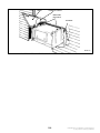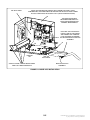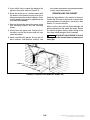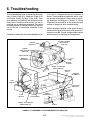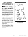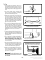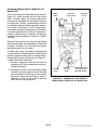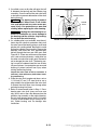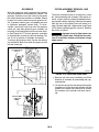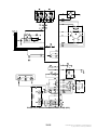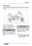
1
Service Manual KV KVC KVD Printed in U.S.A. Begin Spec C Model KV, Spec A, Models KVC & KVD 11-04 981-0518E Redistribution or publication of this document, by any means, is strictly prohibited. ! ! The engine exhaust from this product contains chemicals known to the State of California to cause cancer, birth defects or other reproductive harm. gasoline warnings Redistribution or publication of this document, by any means, is strictly prohibited. Table of Contents SECTION PAGE SAFETY PRECAUTIONS . . . . . . . . . . . . . . . . . . . . . . . . . . . . . . . . . . . . . . . . . . . . . . . . . . . . . iii 1. INTRODUCTION . . . . . . . . . . . . . . . . . . . . . . . . . . . . . . . . . . . . . . . . . . . . . . . . . . . . . . . . . . 1-1 2. SPECIFICATIONS . . . . . . . . . . . . . . . . . . . . . . . . . . . . . . . . . . . . . . . . . . . . . . . . . . . . . . . . . 2-1 3. CLEARANCES AND DIMENSIONS . . . . . . . . . . . . . . . . . . . . . . . . . . . . . . . . . . . . . . . . . . 3-1 4. TORQUE SPECIFICATIONS . . . . . . . . . . . . . . . . . . . . . . . . . . . . . . . . . . . . . . . . . . . . . . . . 4-1 5. PREPARING FOR SERVICE . . . . . . . . . . . . . . . . . . . . . . . . . . . . . . . . . . . . . . . . . . . . . . . 5-1 Troubleshooting . . . . . . . . . . . . . . . . . . . . . . . . . . . . . . . . . . . . . . . . . . . . . . . . . . . . . . . 5-1 Special Tools . . . . . . . . . . . . . . . . . . . . . . . . . . . . . . . . . . . . . . . . . . . . . . . . . . . . . . . . . 5-1 Safety Considerations . . . . . . . . . . . . . . . . . . . . . . . . . . . . . . . . . . . . . . . . . . . . . . . . . 5-2 Removing the Genset . . . . . . . . . . . . . . . . . . . . . . . . . . . . . . . . . . . . . . . . . . . . . . . . . 5-3 Reinstalling the Genset . . . . . . . . . . . . . . . . . . . . . . . . . . . . . . . . . . . . . . . . . . . . . . . . 5-8 6. TROUBLESHOOTING . . . . . . . . . . . . . . . . . . . . . . . . . . . . . . . . . . . . . . . . . . . . . . . . . . . . . 6-1 Troubleshooting Control . . . . . . . . . . . . . . . . . . . . . . . . . . . . . . . . . . . . . . . . . . . . . . . . 6-3 Troubleshooting Generator . . . . . . . . . . . . . . . . . . . . . . . . . . . . . . . . . . . . . . . . . . . . . 6-15 Troubleshooting Engine Primary Systems . . . . . . . . . . . . . . . . . . . . . . . . . . . . . . . . 6-18 7. CONTROL . . . . . . . . . . . . . . . . . . . . . . . . . . . . . . . . . . . . . . . . . . . . . . . . . . . . . . . . . . . . . . . 7-1 Control Description . . . . . . . . . . . . . . . . . . . . . . . . . . . . . . . . . . . . . . . . . . . . . . . . . . . . 7-1 Control Operation . . . . . . . . . . . . . . . . . . . . . . . . . . . . . . . . . . . . . . . . . . . . . . . . . . . . . 7-4 Control Component Tests . . . . . . . . . . . . . . . . . . . . . . . . . . . . . . . . . . . . . . . . . . . . . . 7-5 8. ENGINE PRIMARY SYSTEMS . . . . . . . . . . . . . . . . . . . . . . . . . . . . . . . . . . . . . . . . . . . . . . 8-1 Exhaust System . . . . . . . . . . . . . . . . . . . . . . . . . . . . . . . . . . . . . . . . . . . . . . . . . . . . . . 8-1 Cooling System . . . . . . . . . . . . . . . . . . . . . . . . . . . . . . . . . . . . . . . . . . . . . . . . . . . . . . . 8-6 Ignition System . . . . . . . . . . . . . . . . . . . . . . . . . . . . . . . . . . . . . . . . . . . . . . . . . . . . . . . 8-8 Crankcase Ventilation . . . . . . . . . . . . . . . . . . . . . . . . . . . . . . . . . . . . . . . . . . . . . . . . . 8-10 Governor . . . . . . . . . . . . . . . . . . . . . . . . . . . . . . . . . . . . . . . . . . . . . . . . . . . . . . . . . . . . . 8-11 Gasoline Fuel System . . . . . . . . . . . . . . . . . . . . . . . . . . . . . . . . . . . . . . . . . . . . . . . . . 8-13 LPG Fuel System . . . . . . . . . . . . . . . . . . . . . . . . . . . . . . . . . . . . . . . . . . . . . . . . . . . . . 8-21 Electric Starter . . . . . . . . . . . . . . . . . . . . . . . . . . . . . . . . . . . . . . . . . . . . . . . . . . . . . . . . 8-26 i Redistribution or publication of this document, by any means, is strictly prohibited. SECTION PAGE 9. GENERATOR . . . . . . . . . . . . . . . . . . . . . . . . . . . . . . . . . . . . . . . . . . . . . . . . . . . . . . . . . . . . . 9-1 Generator Description . . . . . . . . . . . . . . . . . . . . . . . . . . . . . . . . . . . . . . . . . . . . . . . . . 9-1 Generator Operation . . . . . . . . . . . . . . . . . . . . . . . . . . . . . . . . . . . . . . . . . . . . . . . . . . 9-2 Voltage Regulator Tests . . . . . . . . . . . . . . . . . . . . . . . . . . . . . . . . . . . . . . . . . . . . . . . . 9-3 Field Voltage Tests . . . . . . . . . . . . . . . . . . . . . . . . . . . . . . . . . . . . . . . . . . . . . . . . . . . . 9-4 Generator Tests . . . . . . . . . . . . . . . . . . . . . . . . . . . . . . . . . . . . . . . . . . . . . . . . . . . . . . . 9-4 Generator Service . . . . . . . . . . . . . . . . . . . . . . . . . . . . . . . . . . . . . . . . . . . . . . . . . . . . . 9-8 Brushes and Slip Rings . . . . . . . . . . . . . . . . . . . . . . . . . . . . . . . . . . . . . . . . . . . . . . . . 9-12 Rotor Bearing Replacement . . . . . . . . . . . . . . . . . . . . . . . . . . . . . . . . . . . . . . . . . . . . 9-13 10. ENGINE BLOCK ASSEMBLY . . . . . . . . . . . . . . . . . . . . . . . . . . . . . . . . . . . . . . . . . . . . . . 10-1 Introduction . . . . . . . . . . . . . . . . . . . . . . . . . . . . . . . . . . . . . . . . . . . . . . . . . . . . . . . . . . 10-1 Leak Down Test . . . . . . . . . . . . . . . . . . . . . . . . . . . . . . . . . . . . . . . . . . . . . . . . . . . . . . . 10-1 Oil Pan and Oil Level Switch . . . . . . . . . . . . . . . . . . . . . . . . . . . . . . . . . . . . . . . . . . . . 10-2 Head Cover . . . . . . . . . . . . . . . . . . . . . . . . . . . . . . . . . . . . . . . . . . . . . . . . . . . . . . . . . . 10-3 Cylinder Head . . . . . . . . . . . . . . . . . . . . . . . . . . . . . . . . . . . . . . . . . . . . . . . . . . . . . . . . 10-3 Valve System . . . . . . . . . . . . . . . . . . . . . . . . . . . . . . . . . . . . . . . . . . . . . . . . . . . . . . . . . 10-4 Crankcase Cover . . . . . . . . . . . . . . . . . . . . . . . . . . . . . . . . . . . . . . . . . . . . . . . . . . . . . 10-7 Camshaft and Tappet Removal . . . . . . . . . . . . . . . . . . . . . . . . . . . . . . . . . . . . . . . . . 10-7 Governor . . . . . . . . . . . . . . . . . . . . . . . . . . . . . . . . . . . . . . . . . . . . . . . . . . . . . . . . . . . . . 10-8 Piston Assembly Removal and Service . . . . . . . . . . . . . . . . . . . . . . . . . . . . . . . . . . 10-8 Crankshaft . . . . . . . . . . . . . . . . . . . . . . . . . . . . . . . . . . . . . . . . . . . . . . . . . . . . . . . . . . . 10-13 Cylinder Block . . . . . . . . . . . . . . . . . . . . . . . . . . . . . . . . . . . . . . . . . . . . . . . . . . . . . . . . 10-14 Timing Gears . . . . . . . . . . . . . . . . . . . . . . . . . . . . . . . . . . . . . . . . . . . . . . . . . . . . . . . . . 10-16 Bearings . . . . . . . . . . . . . . . . . . . . . . . . . . . . . . . . . . . . . . . . . . . . . . . . . . . . . . . . . . . . . 10-16 Oil Seal . . . . . . . . . . . . . . . . . . . . . . . . . . . . . . . . . . . . . . . . . . . . . . . . . . . . . . . . . . . . . . 10-16 Compression Release System . . . . . . . . . . . . . . . . . . . . . . . . . . . . . . . . . . . . . . . . . . 10-17 11. SERVICE CHECK LIST . . . . . . . . . . . . . . . . . . . . . . . . . . . . . . . . . . . . . . . . . . . . . . . . . . . 11-1 12. WIRING DIAGRAMS . . . . . . . . . . . . . . . . . . . . . . . . . . . . . . . . . . . . . . . . . . . . . . . . . . . . . 12-1 ii Redistribution or publication of this document, by any means, is strictly prohibited. SAFETY PRECAUTIONS Thoroughly read the OPERATOR’S MANUAL before operating the genset. Safe operation and top performance can be obtained only when equipment is operated and maintained properly. moving or electrically live parts can cause severe personal injury or death. S Used engine oil has been identified by some state and federal agencies as causing cancer or reproductive toxicity. Do not ingest, inhale, or contact used oil or its vapors. The following symbols in this manual alert you to potential hazards to the operator, service person and equipment. S Benzene and lead in some gasolines have been identified by some state and federal agencies as causing cancer or reproductive toxicity. Do not to ingest, inhale or contact gasoline or its vapors. DANGER alerts you to an immediate hazard which will result in severe personal injury or death. S Keep multi-class ABC fire extinguishers handy. Class A fires involve ordinary combustible materials such as wood and cloth; Class B fires, combustible and flammable liquid fuels and gaseous fuels; Class C fires, live electrical equipment. (ref. NFPA No. 10) WARNING alerts you to a hazard or unsafe practice which can result in severe personal injury or death. CAUTION alerts you to a hazard or unsafe practice which can result in personal injury or equipment damage. S Genset installation and operation must comply with all applicable local, state and federal codes and regulations. Electricity, fuel, exhaust, moving parts and batteries present hazards which can result in severe personal injury or death. GENERATOR VOLTAGE IS DEADLY! GENERAL PRECAUTIONS S Disable the automatic genset starting feature of an inverter-charger or other automatic starting device before servicing the genset. S Keep children away from the genset. S Do not use evaporative starting fluids. They are highly explosive. S Generator electrical output connections must be made by a trained and experienced electrician in accordance with applicable codes. S To prevent accidental or remote starting while working on the genset, disconnect the negative (−) battery cable at the battery. S The genset must not be connected to shore power or to any other source of electrical power. Back-feed to shore power can cause electric shock resulting in severe personal injury or death and damage to equipment. An approved switching device must be used to prevent interconnections. S Keep the genset and its compartment clean. Excess oil and oily rags can catch fire. Dirt and gear stowed in the compartment can restrict cooling air. S Make sure all fasteners are secure and torqued properly. S Do not work on the genset when mentally or physically fatigued or after consuming alcohol or drugs. S Use caution when working on live electrical equipment. Remove jewelry, make sure clothing and shoes are dry, stand on a dry wooden platform or rubber insulating mat and use tools with insulated handles. S You must be trained and experienced to make adjustments while the genset is running—hot, iii Redistribution or publication of this document, by any means, is strictly prohibited. S Leaks can lead to explosive accumulations of gas. Natural gas rises when released and can accumulate under hoods and inside housings and buildings. LPG sinks when released and can accumulate inside housings and basements and other below-grade spaces. Prevent leaks and the accumulation of gas. ENGINE EXHAUST IS DEADLY! S Inspect for exhaust leaks at every startup and after every eight hours of running. S Learn the symptoms of carbon monoxide poisoning in this manual. S Never sleep in the vehicle while the genset is running unless the vehicle is equipped with a working carbon monoxide detector. BATTERY GAS IS EXPLOSIVE S Make sure there is ample fresh air when operating the genset in a confined area. S Wear safety glasses. S Do not smoke. S Disable the automatic genset starting feature of an inverter-charger or other automatic starting device before storing the vehicle or parking it in a garage or other confined space. S To reduce arcing when disconnecting or reconnecting battery cables, always disconnect the negative (−) battery cable first and reconnect it last. S The exhaust system must be installed in accordance with the genset Installation Manual. MOVING PARTS CAN CAUSE SEVERE PERSONAL INJURY OR DEATH S Engine cooling air must not be used for heating the working or living space or compartment. S Disable the automatic genset starting feature of an inverter-charger or other automatic starting device before servicing the genset. FUEL IS FLAMMABLE AND EXPLOSIVE S Do not smoke or turn electrical switches ON or OFF where fuel fumes are present or in areas sharing ventilation with fuel tanks or equipment. Keep flame, sparks, pilot lights, arc-producing equipment and switches and all other sources of ignition well away. S Do not wear loose clothing or jewelry near moving parts such as PTO shafts, fans, belts and pulleys. S Keep hands away from moving parts. S Fuel lines must be secured, free of leaks and separated or shielded from electrical wiring. S Keep guards in place over fans, belts, pulleys, and other moving parts. MOBILE 7 iv Redistribution or publication of this document, by any means, is strictly prohibited. 1. Introduction This is the service manual for the KV, KVC, KVD series of generator sets (gensets). Read and carefully observe all of the instructions and safety precautions in this manual. MODEL KV / KVD Improper service or parts replacement can lead to severe personal injury or death and to damage to equipment and property. Service personnel must be qualified to perform electrical and mechanical service. WARNING Unauthorized modifications or replacement of fuel, exhaust, air intake or speed control system components that affect engine emissions are prohibited by law in the State of California. WARNING LPG (liquified petroleum gas) is flammable and explosive and can cause asphyxiation. NFPA 58, Section 1.6 requires all persons handling LPG to be trained in proper handling and operating procedures. WARNING See the Operator’s Manual for instructions concerning operation, maintenance and storage and for recommendations concerning engine lubricating oil and fuel. [The engine family designation, engine displacement, statement of compliance with the applicable EPA and / or California emissions regulations, including the compliance period or category, appear in this block on the actual nameplate on the genset.] See the Installation Manual for important recommendations concerning the installation and for a list of the installation codes and standards for safety which may be applicable. See the Parts Manual for parts identification numbers and required quantities and for exploded views of the genset subassemblies. Genuine Onan replacement parts are recommended for best results. When contacting Onan for parts or product information, be ready to provide the model and serial numbers on the genset nameplate. Figure 1-1 illustrates the nameplate and its location. Every character in these numbers is significant. (The last character of the model number is the specification letter, which is important for obtaining the right parts.) MODEL KVC FIGURE 1-1. TYPICAL NAMEPLATE 1-1 Redistribution or publication of this document, by any means, is strictly prohibited. Redistribution or publication of this document, by any means, is strictly prohibited. 2. Specifications KV MODELS GASOLINE 2.8 KV LPG 2.0 KV 2.3 KV 2.5 KV 2.0 KV GENERATOR: 2-Pole Revolving Field, Self-Excited, Electronically Regulated, 1-Phase Power 2800 watts 2000 watts 2300 watts 2500 watts 2000 watts Frequency 60 Hertz* 50 Hertz 50 Hertz 60 Hertz* 50 Hertz Voltage 120 volts 220 volts 230 volts 120 volts 220/230 volts Current 23.3 amperes 9.1 amperes 10 amperes 20.8 amperes 9.1/8.7 amperes Speed 3600 rpm 3000 rpm 3000 rpm 3600 rpm 3000 rpm 0.16 gph (0.6 l/h) 0.28 gph (1.1 l/h) 0.46 gph (1.7 l/h) 0.16 gph (0.6 l/h) 0.23 gph (0.9 l/h) 0.32 gph (1.2 l/h) 0.16 gph (0.6 l/h) 0.23 gph (0.9 l/h) 0.32 gph (1.2 l/h) FUEL CONSUMPTION: No load Half load Full load 1.0 lbs/h (0.44 kg/h) 0.9 lbs/h (0.40 kg/h) 1.5 lbs/h (0.68 kg/h) 1.3 lbs/h (0.59 kg/h) 2.5 lbs/h (1.1 kg/h) 2.1 lbs/h (0.92 kg/h) ENGINE: 1-Cylinder, 4-Cycle, Spark-Ignited, OHV, Air Cooled Bore 2.64 inch (67 mm) 2.64 inch (67 mm) Stroke 2.2 inch (56 mm) 2.2 inch (56 mm) Displacement 12 inch3 12 inch3 (197 cc) (197 cc) Compression Ratio 8.5 : 1 8.5 : 1 Oil Capacity** 1 quart (0.95 l) 1 quart (0.95 l) Intake Valve Clearance (Cold) 0.002 inch (0.05 mm) 0.002 inch (0.05 mm) Exhaust Valve Clearance (Cold) 0.002 inch (0.05 mm) 0.002 inch (0.05 mm) Spark Plug Gap 0.025 inch (0.64 mm) 0.020 inch (0.51 mm) 13 lbs-ft (17 N-m) 13 lbs-ft (17 N-m) 25° BTDC, non-adjustable 25° BTDC, non-adjustable − 9 to 13 inch (229 to 330 mm) W.C. (water column) Nominal Battery Voltage 12 volts 12 volts Min. Battery Cold Cranking Capacity 360 amperes 360 amperes 5 amperes 5 amperes Spark Plug Torque Ignition Timing (magneto type ignition) LPG Vapor Supply Pressure DC SYSTEM: Control Fuse * − 60 Hertz models are Listed by CSA and the U.S. Testing Company. ** −See Periodic Maintenance in the Operator’s Manual for oil filling instructions. 2-1 Redistribution or publication of this document, by any means, is strictly prohibited. KVC MODELS GENERATOR: 2-Pole Revolving Field, Self-Excited, 1-Phase, Electronically Regulated Power 2800 watts 2800 watts Frequency 60 Hertz* 60 Hertz Voltage 120 volts 100 volts Current 23.3 amperes 28 amperes Speed 3600 rpm 3600 rpm FUEL CONSUMPTION (GASOLINE): Gasoline Gasoline 0.16 gph (0.6 l/h) 0.28 gph (1.1 l/h) 0.46 gph (1.7 l/h) 0.16 gph (0.6 l/h) 0.28 gph (1.1 l/h) 0.46 gph (1.7 l/h) No load Half load Full load ENGINE: 1-Cylinder, 4-Stroke Cycle, Spark-Ignited, OHV, Air Cooled, Mechanically Governed Bore 2.64 inch (67 mm) 2.64 inch (67 mm) Stroke 2.2 inch (56 mm) 2.2 inch (56 mm) Displacement 12 Compression Ratio inch3 12 inch3 (197 cc) (197 cc) 8.5 : 1 Oil Capacity 8.5 : 1 1 quart (0.95 l) 1 quart (0.95 l) Intake Valve Lash (Cold) 0.002 inch (0.05 mm) 0.002 inch (0.05 mm) Exhaust Valve Lash (Cold) 0.002 inch (0.05 mm) 0.002 inch (0.05 mm) Spark Plug Gap 0.025 inch (0.64 mm) 0.025 inch (0.64 mm) Spark Plug Tightening Torque Ignition Timing (magneto type ignition) 13 lbs-ft (17 N-m) 13 lbs-ft (17 N-m) 25° BTDC, non-adjustable 25° BTDC, non-adjustable DC SYSTEM: Nominal Battery Voltage Min. Battery Rating: Cold Cranking Amps (CCA) @ 0° F (−18° C) 12 volts 12 volts 360/450 above/below 32° F (0° C) 360/450 above/below 32° F (0° C) 5 amperes 5 amperes Control Fuse INSTALLATION: Weight of Genset (with engine oil) 100 lbs (45 kg) Minimum Compartment Size (H x D x W)** 15.5 inch x 17.5 inch x 20.2 inch (394 mm x 445 mm x 512 mm) Minimum Free Air Inlet Area 40 inch2 (258 cm2) Muffler Outlet Collar O. D. 1.13 inch Fuel Connection 1/4 inch barb fitting for gasoline hose * Listed by CSA and the U. S. Testing Company. ** See the Installation Manual for additional considerations when sizing the genset compartment. 2-2 Redistribution or publication of this document, by any means, is strictly prohibited. KVD MODELS GASOLINE LPG GENERATOR: 2-Pole Revolving Field, Self-Excited, 1-Phase, Electronically Regulated Power 2800 watts 2500 watts Frequency 60 Hertz 60 Hertz Voltage 120 volts 120 volts Current 23.3 amps 20.8 amps Speed 3600 rpm 3600 rpm FUEL CONSUMPTION: No load Half load Full load Gasoline LPG 0.20 gph (0.76 l/h) 0.30 gph (1.14 l/h) 0.43 gph (1.63 l/h) 0.85 lbs/h (0.39 kg/h) 1.45 lbs/h (0.66 kg/h) 2.35 lbs/h (1.07 kg/h) ENGINE: 1-Cylinder, 4-Stroke Cycle, Spark-Ignited, OHV, Air Cooled, Mechanically Governed Bore 2.64 in (67 mm) 2.64 in (67 mm) Stroke 2.2 in (56 mm) 2.2 in (56 mm) Displacement 12 in3 (197 cc) 12 in3 (197 cc) Compression Ratio 8.5 : 1 8.5 : 1 Oil Capacity 1 quart (0.95 liter) 1 quart (0.95 liter) Intake Valve Lash (Cold) 0.002 in (0.05 mm) 0.002 in (0.05 mm) Exhaust Valve Lash (Cold) 0.002 in (0.05 mm) 0.002 in (0.05 mm) Spark Plug Gap 0.025 in (0.64 mm) 0.020 inch (0.51 mm) Spark Plug Tightening Torque Ignition Timing (magneto type ignition) 13 lbs-ft (17 N-m) 13 lbs-ft (17 N-m) 25° BTDC, non-adjustable 25° BTDC, non-adjustable DC SYSTEM: Nominal Battery Voltage 12 volts Min CCA Rating − SAE @ 32° F (0° C) 360/450 above/below 32° F (0° C) Control Fuse 5 amp INSTALLATION: Noise 71 dB(A)* Weight of Genset (with muffler) 111.6 lbs (50.6 kg) Weight of Genset (without muffler) 107.2 lbs (48.6 kg) Minimum Compartment Size (H x D x W)** 12.52 in x 18.20 in x 20.46 in (317.9 mm x 462.2 mm x 519.8 mm) Minimum Free Air Inlet Area 24 in2 (155 cm2) Muffler Outlet Collar O. D. 1.13 in (28.3 mm) Maximum Exhaust Back Pressure 20 in WC Gasoline Fuel Connection 1/4 in Hose Barb Maximum Gasoline Fuel Pump Lift 3 ft (1 m) LPG Vapor Fuel Connection 1/4 in NPTF LPG Vapor Connection Pressure 9-13 in (228-330 mm) WC * In a typical RV installation at half load and distance of 10 ft (3 m). ** See the Installation Manual for additional considerations when sizing the genset compartment. 2-3 Redistribution or publication of this document, by any means, is strictly prohibited. Redistribution or publication of this document, by any means, is strictly prohibited. 3. Clearances and Dimensions ITEM INCHES MILLIMETERS 0.00394/3.39370 0.100/100.0 (18-24 ft•lb) (25-33 N•m) CYLINDER HEAD Cylinder Head Deformation Limit Torque VALVE Valve Face Angle Valve Stem Diameter Intake 44.5°-45° Exhaust 44.5°-45° Intake 0.2153-0.2157 5.468-5.480 Exhaust 0.2142-0.2150 5.440-5.460 0.2165-0.2170 5.500-5.512 Valve Guide Inside Diameter Clearance Between Valve and Guide Stem Reference Valve Intake 0.00079-0.00173 0.020-0.044 Exhaust 0.00157-0.00283 0.040-0.072 0.0039 0.10 Intake 0.00079-0.0031 0.02-0.080 Exhaust 0.00079-0.0031 0.02-0.080 Allowable Limit Valve Clearance (Lash) Intake Opening Valve Opening Closing Timing (when cool) 78° (58° -70° before top dead center) Closing 118° (98° -110° after bottom dead center) Opening 118° (98° -110° after bottom dead center) Exhaust Closing 78° (58° -70° before top dead center) Valve Spring Reference Value 1.299-1.319 33.0-33.5 1.287 32.7 Reference Value 12.94 lb/0.8858 in 5.87 kgf/22.5 m Allowable Limit 11.64 lb/0.8858 in 5.28 kgf/22.5 m 0.0591 1.5 Free Height Allowable Limit Load and Height Allowable Squareness Limit Valve Seat Valve Seat Angle Intake 45° Exhaust 45° Reference Valve 0.0394-0.0512 1.0-1.3 0.0591 1.5 Valve Seat Width Allowable Limit 3-1 Redistribution or publication of this document, by any means, is strictly prohibited. ITEM INCHES MILLIMETERS 0.31 8 0.0014-0.0030 0.035-0.075 0.0039 0.1 Standard Journal Diameter 0.5892-0.5899 14.966-14.984 Clearance Between Camshaft Journal Bearing (Flywheel Side) 0.0006-0.0020 0.016-0.052 Intake 0.9705 24.65 Exhaust 0.9705 24.65 Valve Lifter Outer Diameter Reference Value Clearance Between Valve Lifter and Guide Allowable Limit Camshaft Reference Value Cam Height Allowable Limit Intake 0.9665 24.55 Exhaust 0.9665 24.55 Allowable Side Clearance Limit 0.0079 0.20 Bending Limit 0.0020 0.05 0.0036-0.0056 0.092-0.141 0.0079 0.20 2.6378-2.6386 67.00-67.02 0.0039 0.10 0.0016 0.04 2.6354-2.6362 66.94-66.96 0.0079-0.0157 0.20-0.40 0.0354 0.90 0.0008-0.0024 0.02-0.06 0.0039 0.10 Timing Gear Reference Value Backlash Allowable Limit Cylinder Reference Value Inner Diameter Allowable Limit Minimum Clearance Between Cylinder and Piston Piston Outer Diameter (Skirt Diameter) Piston Ring Gap Reference Value Allowable Limit Clearance Between Ring and Ring Groove Reference Limit Allowable Limit 3-2 Redistribution or publication of this document, by any means, is strictly prohibited. ITEM INCHES MILLIMETERS 0.5906-0.5907 15.000-15.005 Inner Diameter Reference Value 0.5911-0.5915 15.015-15.025 Clearance Between Small end & Piston Pin 0.004-0.0010 0.010-0.025 0.0039 0.10 0.0016 0.04 Piston Pin Outer Diameter Connecting Rod (Small End) Reference Value Allowable Limit Connecting Rod Bending Limit Torsion Limit Bolt Tightening Torque (10.1-14.5 ft•lb) 0.0016 0.04 10.1-14.5 ft•lb (13.7-19.6 N•m) 1.1798-1.1804 29.967-29.982 1.1780 29.92 0.0007-0.0021 0.018-0.054 0.0039 0.10 0.9835-0.9840 24.980-24.993 0.9803 24.9 0.0008-0.0039 0.02-0.10 0.0079 0.20 0.0008 0.02 0-0.0039 0-0.10 Crankshaft Pin Diameter Reference Value Wear Limit Reference Value Crank Pin Oil Clearance Allowable Limit Reference Value Journal Dia Wear Limit Reference Value Side Clearance Allowable Limit Bending Limit Reference Value Axial Play Allowable Limit 0.0079 0.20 Ignition Plug Standard Gap 0.0236-0.0276 0.6-0.7 3-3 Redistribution or publication of this document, by any means, is strictly prohibited. Redistribution or publication of this document, by any means, is strictly prohibited. 4. Torque Specifications Mounting screws and nuts must be tightened to the specified torque settings. All threads must be clean and lubricated with new engine oil. The cylinder head mounting bolts must be tightened in the proper sequence, refer to Section 10. Engine Block Assembly. TABLE 4-1. TORQUE SPECIFICATIONS TORQUE SPECIFICATIONS FOOT-POUNDS NEWTON-METERS Connecting Rod 10 - 14 14 - 20 Head Cover 3.3 - 6 4.4 - 8 Cylinder Head (Cold) 18 - 24 25 - 33 Endbell to Stator Housing Mounting Screws 6-9 8 - 12 Engine Cooling Shrouds 6-9 8 - 12 Fan Mounting Screws 6-9 8 - 12 11 - 14 14 - 19 Generator Housing to Engine Mounting Nuts 6-7 8-9 Intake Manifold 6-8 7 - 11 Carburetor Mounting Nut 8 - 15 11 - 20 Muffler Bkt to Engine 10 - 14 14 - 20 5-9 7 - 12 22 - 27 30 - 37 6-9 8 - 12 Oil Drain Plug 18 - 24 25 - 33 Oil Watch Bolt 6-9 8 - 12 Rotor Through-bolt 40 - 50 54 - 68 Spark Plug 8 - 18 10 - 24 Starter Bkt. to Engine 6-9 8 - 13 Starter Bkt to Starter 2.5 - 3.3 3.4 - 4.5 Starter Flange to Endbell Mounting Screws 16 - 24 22 - 33 Governor Lever Nut 6-8 7 - 11 Speed Adjust Lever Nut 8 - 15 11 - 20 Vibration Isolators 4-6 5.5 - 8.0 Gearcase Cover Muffler Flange to Engine Oil Base and Generator Housing to Mounting Stud Oil Base to Engine 4-1 Redistribution or publication of this document, by any means, is strictly prohibited. When engine torques are not specified in Table 4-1, tighten the screws and nuts according to Tables 4-2 and 4-3. The grade numbers are indicated on top of the screw or bolt head. TABLE 4-2. METRIC BOLT TORQUE SPECIFICATIONS - NO GRADE OR 8.8 GRADE SIZE FOOT - POUNDS NEWTON - METERS M6 6-7 8-9 M8 13 - 15 18 - 21 M10 29 - 33 39 - 45 M12 46 - 54 63 - 73 TABLE 4-3. METRIC BOLT TORQUE SPECIFICATIONS - 10.9 GRADE SIZE FOOT - POUNDS NEWTON - METERS M6 7-8 10 - 11 M8 17 - 20 24 - 27 M10 35 - 41 48 - 56 M12 57 - 67 77 - 90 4-2 Redistribution or publication of this document, by any means, is strictly prohibited. 5. Preparing for Service Leak down tester Pressure gauge Spark plug gap gauge Flywheel puller Gear separator Cylinder ridge reamer Piston ring compressor Piston ring spreader Cylinder hone Valve seat cutter Wire brush Piston groove cleaner Outside micrometer set (0 to 4 in.) Telescoping gauge set (1/2 in. to 6 in.) Hole gauge (0.300 in. to 0.400 in.) TROUBLESHOOTING Before starting to service the genset, follow the troubleshooting procedures in Section 6. Troubleshooting. The troubleshooting section has been divided into the following sections: S Control (Page 6-3) S Generator (Page 6-15) S Engine Primary Systems (Page 6-18) Each troubleshooting section lists typical problems along with possible causes and corrective actions. Note that some problems might have several possible causes. It may be necessary to investigate several possible causes in order to isolate the actual source of the problem. Generator and Control Tools SPECIAL TOOLS The following special tools are required to service the genset. Some of these tools may be purchased from Onan distributors (see Onan Tool Catalog 900-0019) or from other suppliers. Lead or dead-blow hammer Battery hydrometer VOM multi-tester Frequency Meter Armature growler Load test panel Jumper wires Fan hub assembly holding tool Engine Tools Torque wrench (0 - 100 Ft-Lbs or 0 - 130 N•m) Feeler gauge 5-1 Redistribution or publication of this document, by any means, is strictly prohibited. Reduce the hazard: A safe, orderly work area and well-maintained equipment reduce the risk of hazard. Leave all guards and shields in place on machinery, and maintain equipment in top condition. Store flammable liquids in approved containers, away from fire, flame, spark, pilot light, arc-producing equipment and other ignition sources. Keep the work area clean, well-lighted, and well-ventilated. Keep fire extinguishers and safety equipment nearby, and be prepared for any emergency. SAFETY CONSIDERATIONS Always consider the safety aspects of any service procedure. Servicing gensets presents several hazards that the service technician must be aware of to safely complete the job. Study SAFETY PRECAUTIONS (p. iii) and familiarize yourself with the hazards listed in Table 5-1. Approach the job in a safetyconscious manner. Being safety conscious is the most effective way to avoid injury to yourself and to others. Reduce the risk of an accident by adopting the following safeguards. Develop safe work habits: Unsafe practices are the cause of most accidents involving tools or machinery. Be familiar with your tools and machines and learn how to use them safely. Use the right tool for the job, and check its condition before starting. Follow all warnings and cautions in this manual, and take extra precautions when working around electrical equipment. Avoid working alone, and do not take risks. Do not work when tired or after consuming any alcohol or drug that makes the operation of equipment unsafe. Safeguards to Avoid Hazards Use personal protection: Protect your body by wearing the appropriate safety equipment such as: S Safety shoes S Gloves S Safety glasses Be prepared for a potential accident: The Red Cross and public safety departments offer courses in first aid, CPR, and fire control. Use this information to be ready for an accident. Be safety-conscious, and make safety procedures part of the work routine. S Hard hats S Ear plugs Do not wear rings, jewelry or loose clothing: these can get caught on equipment or conduct electricity. TABLE 5-1. HAZARDS AND THEIR SOURCES • Fire and explosions • Electrical shock (AC) Leaking or spilled fuel Hydrogen gas from charging battery Oily rags improperly stored Flammable liquids improperly stored Any fire, flame, spark, pilot light, arcproducing equipment or other ignition sources Improper genset load connections Faulty RV wiring Faulty electrical appliance Faulty genset wiring Working in damp conditions Jewelry touching electrical components • Rotating Machinery • Burns Jewelry or loose clothing catching in moving parts Hot exhaust pipes Hot engine and generator surfaces Hot engine oil Electrical short in DC wiring system • Slippery Surfaces Leaking or spilled oil • Poisonous gases • Heavy Objects Carbon monoxide from faulty exhaust Operating genset where exhaust gases can accumulate Removing genset from vehicle Removing heavy components 5-2 Redistribution or publication of this document, by any means, is strictly prohibited. With the under-floor mount installation (see Figure 5-2), special brackets are used to suspend the genset under the floor of the vehicle. The mounting brackets bolt to special support members that are built into the vehicle framework. The genset is mounted near the exterior of the vehicle. Access is provided through a door located in the exterior of the vehicle. REMOVING THE GENSET Some service procedures will require removing the genset from the coach. While there are many variations, Model KV and KVD genset installations are generally either compartment mount or under-thefloor mount. (Model KVD gensets have an external muffler mounted below the genset which must be removed before the genset is removed.) Figure 5-3 illustrates the Model KVC genset installation. In a compartment mount installation, a special compartment (see Figure 5-1) is built into the coach to house the genset. The compartment is constructed with a vapor-tight barrier that seals off the genset from the coach interior. The genset is usually fastened to the floor of the compartment which must be able to support the weight of the genset. Access to the compartment is through a door located in the exterior of the coach. DOOR Because of the wide variety of genset installations, it is not possible to specify the exact removal procedures for each genset. If, after examining the installation, a satisfactory method for removing the genset cannot be determined, contact the RV coach manufacturer to obtain their recommendations. FUEL AND ELECTRICAL CONNECTIONS (LEFT SIDE) MOUNTING HOLES BARRIER COMPARTMENT FLOOR M1723−2s FIGURE 5-1. TYPICAL MODEL KV AND KVD COMPARTMENT INSTALLATION 5-3 Redistribution or publication of this document, by any means, is strictly prohibited. DOOR FLOOR OF COACH MOUNTING BRACKETS BARRIER M1724−2s FIGURE 5-2. TYPICAL MODEL KV AND KVD UNDER-FLOOR INSTALLATION 5-4 Redistribution or publication of this document, by any means, is strictly prohibited. AIR SEAL PANEL STEEL ENCLOSURE AND COOLING AIR PLENUM THAT SEALS TIGHT AROUND SIDES, TOP AND FRONT TO PREVENT AIR RECIRCULATION. FRONT ACCESS COVER MUST ALSO SEAL TIGHT (COACH MANUFACTURER) THE DOTS REPRESENT LOCATIONS REQUIRING ACCESS FOR OPERATION AND PERIODIC MAINTENANCE UNCLAMP THE FLEXIBLE EXHAUST TUBE AT THE ENGINE AND LOOSEN THE TWO MUFFLER HANGERS TO REMOVE THE ENTIRE MUFFLER/TAILPIPE ASSEMBLY COOLING AIR HOT AIR DISCHARGE VEHICLE FRAME, GENSET OUTRIGGERS AND 2 OF 4 MOUNTING BOLTS MUFFLER/TAILPIPE ASSEMBLY FIGURE 5-3. MODEL KVC INSTALLATION 5-5 Redistribution or publication of this document, by any means, is strictly prohibited. Disconnecting Set from RV Systems WARNING Gasoline and LPG (liquified petroleum gas) are flammable and explosive can cause severe personal injury or death. Do not smoke. Keep flames, sparks, pilot lights, arc-producing and switching equipment, and all other sources of ignition away from fuel tank and system, and areas sharing ventilation. Have an ABC fire extinguisher handy. Disconnect the following items from the genset. Refer to Figures 5-1, 5-2 or 5-3 for component locations in typical genset installations. Some installations may require partial removal of the genset to gain access to the battery cable, fuel line and other connections. Read this section before starting genset removal. 1. Disconnect the vehicle and genset negative (−) battery cables at the battery. For Gasoline-fueled Gensets, disconnect the fuel line from the genset and securely plug the end of the fuel line to prevent leakage or an accumulation of explosive gasoline vapor. Sparks and high current could cause fire and other damage to the battery, battery cables and vehicle if the loose ends of cables connected to the battery touch. Always disconnect the negative (−) battery cable from the battery before disconnecting the battery cables from the genset. WARNING WARNING LPG is flammable and explosive and can cause asphyxiation. NFPA 58, Section 1.6 requires all persons handling LPG to be trained in proper handling and operating procedures. 2. Disconnect the genset positive (+) battery cable from the wire harness. LPG “sinks” and can accumulate in explosive concentrations. Before disconnecting the LPG fuel line, close the fuel shutoff valve(s) at the LPG container(s) and move the vehicle outside and away from pits, basements and other below-grade spaces where LPG could accumulate. 3. Disconnect the remote control wire plug from the genset housing. 4. Disconnect the generator load wires at the RV electrical system junction box. Tag the RV circuit wires for positive identification when reconnecting. 5. Loosen the conduit connector and pull the load wires and flexible conduit free of the junction box. For LPG-fueled Gensets, close the fuel shutoff valve(s) at the LPG container(s) and move the vehicle outside and away from below-grade spaces where LPG could accumulate. To purge most of the LPG from the fuel line and genset, run the genset (if it starts) until it runs out of fuel (LPG container valve closed). To purge some of the remaining LPG, press the regulator primer plunger (Figure 8-23 on Page 8-19 and Figure 8-26 on Page 8-24) while cranking the engine for 10 seconds. Disconnect the fuel line from the genset and plug the end of the hose to prevent fuel from escaping if someone inadvertently opens the shutoff valve(s) at the LPG container(s). 6. For Model KV, disconnect the tail pipe. 7. For Model KVD, disconnect the tail pipe and remove the muffler. 8. For Model KVC, unclamp the flexible exhaust tube from the engine and loosen the two muffler hangers to remove the entire muffler/tail pipe assembly (Figure 5-3). Take care not to damage the flexible exhaust tube. 9. Disconnect the fuel line from the genset. Follow the applicable instructions depending on the fuel. 5-6 Redistribution or publication of this document, by any means, is strictly prohibited. Removing Under-floor Mounted Set from RV WARNING The genset is heavy and can result in severe personal injury if dropped during removal. Use the recommended removal techniques and keep hands and feet clear while removing mounting bolts. When the genset has been disconnected from the electrical, exhaust, and fuel systems, the genset may be removed for major service work. The genset is mounted on support brackets that are bolted to the underside of the floor on the vehicle or trailer and to the genset housing. Removing Model KVC from RV The genset is completely suspended underneath the floor of the RV by the support brackets. To avoid dropping the genset during removal, follow the recommended genset removal procedures. Remove the air seal panel (Figure 5-3) and make sure to support the genset while removing the four mounting bolts. Then lower the genset until it clears the skirt of the vehicle. (It may be necessary to tip the genset and pull it forward slightly to free the back edge from resting on top of the vehicle frame.) The genset is heavy and can cause severe personal injury if dropped during removal. Use the recommended removal techniques and keep hands and feet clear while removing mounting bolts. WARNING Removing Compartment Mounted Set from RV When the genset has been disconnected from the electrical, exhaust, and fuel systems, examine the genset mounting and support system. Locate all mounting bolts and support members for the genset. In most installations, the genset housing will be bolted to the coach framework. Depending on the installation, the genset may be removable from the side, back, or bottom. Park the recreational vehicle on as level a surface as possible. Then follow these steps very carefully. 1. Put the vehicle in its park position, lock the brakes, and remove the keys (if applicable). Make sure no one moves the vehicle while performing this procedure. WARNING Dropping the genset can result in severe personal injury or death. Make sure no one moves the vehicle during this procedure and that the procedure is performed very carefully and only as instructed. Verify that the genset is adequately supported before loosening any of the mounting bolts or support members. The most satisfactory way to lift or move the genset is to use a forklift truck. 5-7 Redistribution or publication of this document, by any means, is strictly prohibited. 2. Use a forklift truck to support the weight of the genset at the points shown in Figure 5-4. fuel system components are connected exactly as they were before removal. 3. Raise the forklift just so it makes contact with the bottom of the genset housing, then put a little upward pressure under the genset. Verify that the weight of the genset is supported by the forks before proceeding. REINSTALLING THE GENSET Generally, reinstallation is the reverse of removal. Contact the RV coach manufacturer to obtain their recommendations if installation is not obvious. See Section 11. Service Checklist. 4. Remove the bolts that secure the genset to the side mounting brackets and rear mounting braces. Make sure the vapor and fire shields between the genset and interior of the vehicle are secure. Reseal any holes through the barriers where wiring or fuel lines were pulled through or bolts loosened. 5. Slowly lower the genset until it clears all obstructions and can be safely moved out from under the vehicle. EXHAUST GAS IS DEADLY! Seal all openings into the vehicle interior to keep out exhaust gas. WARNING 6. When reinstalling the genset, be sure that all bolts, brackets, and electrical, exhaust, and FORKLIFT FIGURE 5-4. COMPLETE SET REMOVAL (MODEL KV) 5-8 Redistribution or publication of this document, by any means, is strictly prohibited. 6. Troubleshooting cuitry that is energized during the sequence of events. These conditional schematics are for a typical gasoline fueled genset. Always refer to the wiring schematic and diagram in Section 12. Wiring Diagrams that corresponds to the model and spec number of the genset when troubleshooting. This troubleshooting guide is divided into three sections: Control (Page 6-3), Generator (Page 6-15), and Engine Primary Systems (Page 6-18). Common problems are listed with their possible causes. Refer to the Corrective Action column for the appropriate test or adjustment procedure. The section and page number in the right column lists the location of the test or adjustment procedure in this manual. Make a thorough inspection of the genset wiring to make sure that good wire harness and ground connections are made. Correct wiring problems before performing tests or replacing any components. Conditional schematics are used to highlight the cir- BATTERY CHARGE RESISTOR R1 (SPEC C-E) STARTER MOTOR B1 BRIDGE RECTIFIER CR1 (SPEC C-E) BRUSH BLOCK MAGNETO IGNITION G2 SPARK PLUG E1 MODEL KV VOLTAGE REGULATOR VR1 IGNITION COIL T1 CONTROL ASSEMBLY A1 FUEL PUMP E2 START/STOP SWITCH S1 START RELAY K1 CIRCUIT BREAKER CB1 CAPACITOR C1 MODEL KVD VOLTAGE REGULATOR VR1 FUSE F1 FIGURE 6-1. COMPONENT LOCATIONS (MODELS KV AND KVD) 6-1 Redistribution or publication of this document, by any means, is strictly prohibited. ENGINE-GENERATOR-STARTER-MAGNETO-BRUSH BLOCK-SPARK PLUG ASSEMBLY SAME AS MODEL KV (FIGURE 6-1) IGNITION COIL T1 CONTROL BOX COVER FUEL PUMP E2 START/STOP SWITCH S1 START RELAY K1 VOLTAGE REGULATOR VR1 CAPACITOR C1 FUSE F1 IS BUNDLED IN WIRE HARNESS (NOT SHOWN) HOUR METER M1 CIRCUIT BREAKER CB1 CONTROL BOXVIEW FROM BOTTOM, COVER REMOVED CONTROL ASSEMBLY A1 FIGURE 6-2. COMPONENT LOCATIONS (MODEL KVC) 6-2 Redistribution or publication of this document, by any means, is strictly prohibited. Figure 6-1 or 6-2 shows the location of the generator components. Refer to the wiring diagram in Section 12. Wiring Diagrams for wiring connections. TROUBLESHOOTING CONTROL Use the following troubleshooting guide to help locate problems related to the control. Start - Cranking Mode Battery positive (B+) is supplied to the control assembly (A1) through control fuse (F1). Holding the Start/Stop switch (S1) in the Start position activates control assembly (A1) by closing the start signal input circuit. While the Start/Stop switch is held, the control assembly supplies the following outputs: • Battery positive (B+) is supplied to the start relay coil (K1). This energizes the start relay. The start relay contacts close supplying battery positive (B+) to the starter motor B1. The starter begins to crank the engine to initiate starting. START/STOP SWITCH S1 BATTERY BT1 CONTROL ASSEMBLY A1 FUSE F1 STARTER MOTOR B1 START RELAY K1 s P2 P1 INTERNALLY GROUNDED ON KVC J2 J1 FIGURE 6-3. START − CRANKING MODE 6-3 Redistribution or publication of this document, by any means, is strictly prohibited. WARNING Many troubleshooting procedures present hazards that can result in severe personal injury or death. Only trained and experienced personnel with knowledge of fuels, electricity, and machinery hazards should perform service procedures. Review SAFETY PRECAUTIONS, p. iii. TABLE 6-1. CONTROL TROUBLESHOOTING − CRANKING MODE Trouble Possible Cause Corrective Action Engine Does 1. Open control fuse F1. Not Crank 1. Section/ Page Check fuse. If open, locate and correct cause of overload. Replace fuse. 2. Insufficient cranking voltage due to: (Also see Low Bat. Voltage pg. 6-6.) a. Battery not charged. b. Battery connections loose or dirty. c. Battery cable size too small. 2a. Check condition of battery and recharge or replace. 2b. Clean and tighten all connections at battery, K1 start solenoid, and starter motor. 2c. Increase starting battery cable size. 3. Start solenoid (K1) not energized due to: a. Open circuit to start solenoid coil. b. Defective start solenoid coil. c. Defective Start/Stop switch. d. Defective control assembly (A1). 3a. Check wiring continuity to the start solenoid (K1) coil from control assy. (A1) and from ground to start solenoid. 3b. Test start solenoid (K1). 3c. Test Start/Stop switch (S1). 3d. Measure voltage between start solenoid terminal I and ground with switch (S1) held in the Start position. If voltage is not present and continuity and battery check OK, Cont. assy. (A1) is defective. 4. Starter (B1) not energized due to: a. Open circuit to starter (B1). b. Open circuit between battery (B+) and the start solenoid contact (BAT). c. Defective start solenoid (K1) . d. Defective starter (B1). 5. If engine cranks from set but not from remote control panel, fault is due to: a. Open circuit between control assy. (A1) and remote Start/Stop switch. b. Remote Start/Stop switch faulty. 4a. Check continuity between starter lead on start solenoid (S) and gnd. ( 4 ±1 ohm). 4b. Check wiring continuity between battery (B+) and the start solenoid (BAT). 4c. Measure voltage between starter terminal and ground with switch (S1) held in the Start position. If voltage is not present and continuity checks OK, start solenoid (K1) is defective. 4d. If voltage is present in step 4c, starter is defective. 7-6 7-5 7-5 7-5 8-26 5a. Check wiring continuity between control assembly (A1) and remote Start/Stop switch. 5b. Test remote Start/Stop switch. 6-4 Redistribution or publication of this document, by any means, is strictly prohibited. Start - Ignition Mode Holding the Start/Stop switch (S1) in the Start position activates the following ignition circuit: • Control assembly (A1) enables the ignition circuit, this opens a ground path through the control assembly to the magneto assembly (G2) so that output from the magneto will energize the ignition coil (T1). • With the engine cranking, a permanent magnet in the flywheel rotates, at the proper time, past the magneto to induce a voltage that flows to the ignition coil (T1) that fires the spark plug (E1) for ignition. • Battery positive (B+) is supplied to the fuel pump (E2) or fuel shutoff solenoid (E2) and regulator(K2) on LPG models. (Schematic for gasoline fueled model shown). BATTERY BT1 START/STOP SWITCH S1 FUSE F1 CONTROL ASSEMBLY A1 START RELAY K1 STARTER MOTOR B1 OIL LEVEL SWITCH S2 P2 INTERNALLY GROUNDED ON KVC P1 J2 Z1 J1 MAGNETO IGNITION G2 FUEL PUMP E2 (FUEL SHUTOFF SOLENOID ON LPG MODEL) SPARK PLUG E1 IGNITION COIL T1 FIGURE 6-4. START − IGNITION MODE 6-5 Redistribution or publication of this document, by any means, is strictly prohibited. WARNING Many troubleshooting procedures present hazards that can result in severe personal injury or death. Only trained and experienced personnel with knowledge of fuels, electricity, and machinery hazards should perform service procedures. Review SAFETY PRECAUTIONS, p. iii. TABLE 6-2. CONTROL TROUBLESHOOTING − IGNITION MODE Trouble Possible Cause Corrective Action Engine Cranks 1. Restricted fuel supply due to: But Does Not a. Fuel level below pickup tube in tank. Start b. Fuel line supply valve closed. c. Fuel filter clogged. Section/ Page 1a. Add fuel if tank is low. 1b. Open fuel supply valve (if equipped). 1c. Replace clogged fuel filter and check fuel supply for contamination. 8-20 2. Faulty ignition due to worn or fouled spark plug, faulty plug wire, faulty ignition coil or magneto. 2. Refer to Ignition System for test and service procedures. Regap LPG sparkplug to 0.020 inch. 8-8 3. Sticking choke or carburetor mixture screws incorrectly adjusted. 3. Refer to Fuel System for adjustments. 8-16 4. Fuel pump (E2) not working due to: a. Fuel pump defective. b. Open circuit between fuel pump and control assembly (A1) or control assembly is defective. 4a. Measure voltage between fuel pump connector and ground with the engine cranking. If B+ voltage is not present, proceed to 4b. If voltage is present, (min. 6 VDC) fuel pump is defective. 4b. Check continuity between control assembly and fuel pump. If connections are good and voltage was not measured in 4b, replace control assembly (A1). 8-20 5. Faulty fuel solenoid, priming solenoid, or regulator on LPG models. 5. Refer to LPG Fuel System, Section 8 for service procedures. 6. Governor linkage stuck or binding. 6. Check governor arm movement. See Governor section. 7. Oil level switch (S2) closed due to: a. Low oil level. b. Defective low oil level switch. 7a. Check oil level and add oil if low. 7b. Check low oil level switch. 6-6 8-11 10-2 Redistribution or publication of this document, by any means, is strictly prohibited. Start - Field Flash Mode Holding the Start/Stop switch (S1) in the Start position activates the following field flash circuit: • Battery positive (B+) is supplied through the control assembly (A1) to the voltage regulator (VR1) at pin 7. From pins 9 and 10 of the voltage regulator, excitation voltage flows through the brushes to the rotor field winding. • The excitation voltage flashes the generator field winding to ensure that there is adequate magnetism to induce generator voltage buildup. START/STOP SWITCH S1 BATTERY BT1 CONTROL ASSEMBLY A1 FUSE F1 P2 P1 J2 J1 VOLTAGE REGULATOR VR1 BRUSH BLOCK F+ P3 F − FIGURE 6-5. START − FIELD FLASH MODE 6-7 Redistribution or publication of this document, by any means, is strictly prohibited. WARNING Many troubleshooting procedures present hazards that can result in severe personal injury or death. Only trained and experienced personnel with knowledge of fuels, electricity, and machinery hazards should perform service procedures. Review SAFETY PRECAUTIONS, p. iii. TABLE 6-3. CONTROL TROUBLESHOOTING − FIELD FLASH MODE Trouble Possible Cause Corrective Action Engine Starts But Stops When Start Switch Is Released 1. Low oil level. 2. Defective low oil level switch. 1a. Check oil level and add oil if low. 2. Disconnect low oil level switch and check set operation. Replace if defective. 3a. Check wiring continuity to the brush block F1-F2, voltage regulator VR1, control assembly A1 and generator B1-B2 and Q1-Q2 windings. Check connections of P5 and P6 connectors on the generator housing. 3b. Check brushes for wear and for contact with the slip rings. 3c. Check slip rings 4. Perform field voltage test. 3. No field flash voltage due to: a. Open circuit in wiring. b. Brushes not making good contact. with slip rings. c. Slip ring surface is rough or pitted. 4. Defective generator, control assembly A1, or voltage regulator VR1. 6-8 Section/ Page 10-2 9-12 9-4 Redistribution or publication of this document, by any means, is strictly prohibited. Run Mode When the engine starts, release the Start/Stop switch and it will return to the center Run position. The following events occur: • Control assembly (A1) opens the circuit to the start solenoid (K1), which opens the circuit to the starter motor (M1) to stop cranking. Control assembly (A1) also opens the field flash circuit to AVR pin 7. • Voltage from the battery, used to power the control assembly (A1) and the fuel pump (E2), is replaced with output voltage from the generator charge winding B1-B2. (Refer to Battery Charge Mode following this section.) The control assembly senses this output for the start disconnect function. • Remote run output is energized through the control assembly (A1) to power the time meter, battery condition meter and run lamp in the optional remote control. • Voltage from the generator Q1-Q2 windings provide power to the voltage regulator VR1 to use for supplying field current to the generator. (Refer to Generator AC Output Mode in the Generator Troubleshooting section.) START/STOP SWITCH S1 BATTERY BT1 CONTROL ASSEMBLY A1 FUSE F1 P2 P1 J2 Z1 MAGNETO IGNITION G2 J1 FUEL PUMP E2 (FUEL SHUTOFF SOLENOID ON LPG MODEL) SPARK PLUG E1 IGNITION COIL T1 FIGURE 6-6. RUN MODE 6-9 Redistribution or publication of this document, by any means, is strictly prohibited. WARNING Many troubleshooting procedures present hazards that can result in severe personal injury or death. Only trained and experienced personnel with knowledge of fuels, electricity, and machinery hazards should perform service procedures. Review SAFETY PRECAUTIONS, p. iii. TABLE 6-4. CONTROL TROUBLESHOOTING − RUN MODE Trouble Possible Cause Corrective Action Engine Starts and Runs, Then Stops. Set Restarts Immediately or After Cool Down. 1. Fuel level is below genset set fuel pickup tube or oil level is low. 2. Faulty choke operation. 3. Vapor lock from high ambient temperature. 4. Contaminated or incorrect fuel. 1. 2. 3. 4. Remote Control Run Lamp, Time Meter, or Battery Condition Meter Inoperative 1. Open circuit in remote control wiring. 1. 2. If battery condition meter and run lamp work but time meter does not, time meter is defective. 2. Section/ Page Check fuel and oil level and refill if low. Refer to choke section for adjustments. Remove any objects or debris that may restrict airflow. Make sure fuel system is installed correctly. Refill tank with fresh fuel. 8-19 Check continuity between remote control and control assembly (A1). Replace time meter. 3. If time meter works but battery condition 3a. Connect a voltmeter between the meter does not operate: positive terminal on battery charge a. Defective battery condition meter. meter and ground. Use the following to b. Defective zener diode inside remote determine fault: control. If reading equals battery voltage minus 10 volts, battery condition meter is defective. 3b. If reading does not equal battery voltage minus 10 volts, zener diode is defective. 4. Meters and switch function properly but 4. run lamp does not illuminate. Lamp (internal to switch) is burned out. Replace remote Start/Stop switch (S2). 5. If remote switch functions properly for starting and stopping genset but meters and run lamp do not operate, and step 1 checks OK, control assy. (A1) defective. Check remote running output voltage (approximately 12 VDC) during run condition from control assembly J1-2 to ground and from P5-6 to ground. If voltage is not present, replace control assembly (A1). If voltage is present, check continuity of remote control wiring. Turn off the genset, disconnect the remote control, and check for shorts or too many remote accessories. 5. 6. Too much DC load (over 2-amps) connected to the remote output. 6. 6-10 Redistribution or publication of this document, by any means, is strictly prohibited. Battery Charge Mode (Spec C − E) With the genset running, AC voltage is produced in the B1-B2 windings for the battery charge circuit. • The AC output voltage from the B1-B2 winding is converted to DC voltage when it passes through the full-wave rectifier bridge (CR1). The voltage is then supplied through battery charge resistor (R1). The 12-volt DC output (one-ampere maximum) is used to power the control assembly (A1), fuel pump (E2), the remote control, and to prevent discharge of the genset starting battery during genset operation. This output is not sufficient to charge a low or dead battery. START/STOP SWITCH S1 BATTERY BT1 CONTROL ASSEMBLY A1 BATTERY CHARGE RESISTOR R1 BRIDGE RECTIFIER CR1 + P2 AC2 FUSE F1 AC1 P1 − J2 J1 FUEL PUMP E2 (FUEL SHUTOFF SOLENOID ON LPG MODEL) B1 STATOR B2 FIGURE 6-7. BATTERY CHARGE MODE (SPEC C − E) 6-11 Redistribution or publication of this document, by any means, is strictly prohibited. WARNING Many troubleshooting procedures present hazards that can result in severe personal injury or death. Only trained and experienced personnel with knowledge of fuels, electricity, and machinery hazards should perform service procedures. Review SAFETY PRECAUTIONS, p. iii. TABLE 6-5. CONTROL TROUBLESHOOTING − BATTERY CHARGE MODE Trouble Possible Cause Corrective Action Section/ Page Low Battery Voltage 1. Weak or discharged battery due to: a. Low electrolyte level in battery. b. Long periods of non-use. c. Improperly wired battery. d. Load connected to battery while set is turned off. e. Too much DC load on genset starting battery. 1a. Replenish electrolyte and recharge battery. 1b. Connect a separate battery charger to bring battery up to full charge. 1c. Reconnect and check battery connection. 1d. Disconnect load and recharge battery. 1e. Remove other DC loads from genset starting battery. 2. Genset charging circuit not functioning due to: a. Open in circuit between generator B1-B2 winding and battery (B+). b. Open charging resistor (R 1). c. Diode bridge (CR1) defective. d. Generator B1-B2 defective. 2a. Check all wiring connections between the generator B1-B2 windings and the Battery B+ connection, including all connections to the diode bridge (CR1) and battery charge resistor (R1). 2b. Remove wires from the charge resistor (R1) and measure its resistance. A normal reading is 4 to 6 ohms. 2c. Refer to diode bridge (CR1) test 2d. Refer to generator test section. 7-7 7-7 9-4 NOTE: The battery charging circuit is designed to maintain the genset starting battery. The charging circuit will not charge a low or bad battery. A low battery should be fully charged with a battery charger. 6-12 Redistribution or publication of this document, by any means, is strictly prohibited. Stop Mode Momentarily pushing the Start/Stop switch (S1) to the Stop position begins the stop mode with the following results: • Control assembly (A1) de-energizes the ignition enable circuit, grounding the magneto (G2) ignition circuit to stop the engine. • Control assembly (A1) also opens the circuit to the fuel pump (E2) and to the remote control. START/STOP SWITCH S1 CONTROL ASSEMBLY A1 MAGNETO IGNITION G2 SPARK PLUG E1 P2 IGNITION COIL T1 P1 J2 Z1 J1 B1 STATOR B2 FIGURE 6-8. STOP MODE 6-13 Redistribution or publication of this document, by any means, is strictly prohibited. WARNING Many troubleshooting procedures present hazards that can result in severe personal injury or death. Only trained and experienced personnel with knowledge of fuels, electricity, and machinery hazards should perform service procedures. Review SAFETY PRECAUTIONS, p. iii. TABLE 6-6. CONTROL TROUBLESHOOTING − STOP MODE Trouble Possible Cause Corrective Action Genset 1.If set can be stopped from set control Does Not Stop but not from remote control panel, When Switch fault is due to: Is Pushed To a. Open circuit between control assy. Stop (A1) and remote Start/Stop switch. b. Remote Start/Stop switch faulty. Always remove the load a few minutes before stopping the set to allow cool down. 2. If set can be stopped from remote control but not from set, fault due to Start/Stop (S1) switch on control assembly (A1). Section/ Page 1a. Check wiring continuity between control assembly (A1) and remote Start/Stop switch. 1b. Check remote Start/Stop switch. 2a. Check Start/Stop switch (S1). 6-14 7-5 Redistribution or publication of this document, by any means, is strictly prohibited. Figure 6-1 or 6-2shows the location of the generator components. Refer to the wiring diagram in Section 12. Wiring Diagram for wiring connections. TROUBLESHOOTING GENERATOR Use the following troubleshooting guide to help locate problems related to the generator. WARNING Many troubleshooting procedures present hazards that can result in severe personal injury or death. Only trained and experienced personnel with knowledge of fuels, electricity, and machinery hazards should perform service procedures. Review SAFETY PRECAUTIONS, p. iii. TABLE 6-7. GENERATOR TROUBLESHOOTING Trouble Possible Cause Corrective Action Section/ Page No AC Output 1. Open circuit breaker. Voltage 1. Locate cause of overload and correct as required. Reset breaker. Note: 2. Open circuit between voltage this condition regulator and brush block. may cause the genset 3. Open circuit between stator connecto stop when tions Q1 or Q2 and voltage regulator. start switch S1 (This condition will produce approx. is released. 15 to 30 VAC output.) 2. Check for good wiring connections and continuity and correct as required. AC Output Voltage Too Low 3. Check for good wiring connections and continuity and correct as required. 4. Open circuit between battery Pos. (+) and voltage regulator pin 7 for field flash. 4. Check for continuity between control connector J2-3 and voltage regulator connector P3-7. If connections are good and 12 VDC is not present at voltage regulator pin 7 during start, control assembly A1 is defective. 5. Brushes not making good contact with slip rings. 5. Check brushes for wear and for contact. 6. Slip ring surface is rough or pitted. 6. Check slip rings. 7. Capacitor C1 shorted. 8. Defective generator, control assembly A1, or voltage regulator VR1. 7. Check capacitor and replace if defective. 8. Perform field voltage test. 9-4 1. Engine governor out of adjustment. 1. Refer to governor adjustments 8-11 2. Brushes worn or not making good contact with slip rings. 2. Check length of brushes and replace if worn excessively. Check slip rings. 9-12 3. Poor wiring connections to voltage regulator. 3. Check for good wiring connections between the voltage regulator and the brush block and between stator connections Q1and Q2. Correct if required. 4. If generator frequency is within specified limits but voltage is incorrect, voltage regulator is defective. 4. Replace electronic voltage regulator. 6-15 9-12 Redistribution or publication of this document, by any means, is strictly prohibited. Generator AC Output Mode When the engine starts and begins to come up to speed, AC voltage is produced in the battery charge winding B1-B2, the quadrature winding Q1-Q2 and in the AC windings T1-T2. These outputs perform the following functions: • The battery charge winding B1-B2 is used to power the control assembly (A1), fuel pump (E2), the remote control, and to prevent discharge of the genset starting battery during genset operation. This output is not sufficient to charge a low or dead battery. The control assembly A1 monitors this voltage as part of the start disconnect function. • The quadrature winding Q1-Q2 output voltage is fed to the voltage regulator VR1 where it is rectified into DC voltage and fed back to the rotor through the brushes to cause further voltage buildup. Voltage buildup is controlled by the voltage regulator that senses the AC output voltage. The regulator continually measures the output voltage and compares it to an internal reference voltage. When the output voltage exceeds the reference, the regulator causes the current in the rotor to decrease until the proper voltage is obtained. • The AC windings T1-T2 provide the 120 VAC output voltage through the circuit breaker CB1. START/STOP SWITCH S1 CIRCUIT BREAKER CB1 L1 (LOAD) CONTROL ASSEMBLY A1 120 VAC L2 (NEUT) GND STATOR P2 T1 Q1 B1 P1 J2 B2 J1 T2 BRUSH BLOCK Q2 F+ VOLTAGE REGULATOR VR1 F − P3 FIGURE 6-9. GENERATOR OUTPUT MODE 6-16 Redistribution or publication of this document, by any means, is strictly prohibited. WARNING Many troubleshooting procedures present hazards that can result in severe personal injury or death. Only trained and experienced personnel with knowledge of fuels, electricity, and machinery hazards should perform service procedures. Review SAFETY PRECAUTIONS, p. iii. TABLE 6-8. GENERATOR TROUBLESHOOTING Trouble Possible Cause Corrective Action AC Output Voltage Too High 1. Engine governor out of adjustment. 1. Noisy Generator Generator Overheats Section/ Page Refer to governor adjustments 2. If generator frequency is within 2. specified limits but voltage is incorrect, electronic voltage regulator is defective. Replace electronic voltage regulator. 1. Loose brush holder. 2. Worn rotor bearing. 1. 2. Tighten brush holder. Replace rotor bearing. 3. Rotor and stator rubbing together due to: a. Varnish lumps. b. Rotor misaligned with crankshaft. 3a. Check for varnish lumps between rotor and stator, remove as required. 3b. Follow specified assembly procedures to correct rotor to crankshaft alignment. 1. Generator overloaded due to defective circuit breaker. 1. Replace circuit breaker. Do not exceed specified load when operating set. 2. Airflow restricted due to dirt or debris covering vent openings in stator housing. 2. Clear away all dirt or debris as required. 3. Stator windings covered with oil or dirt. 3. Clean stator windings. 4. Defective rotor or stator windings. 4. 5. Loose or missing service access cover or improper seal around the endbell assembly. 5. Test each component for open, grounded, or shorted windings and replace if defective. Check for proper fit of service access cover and check seal around endbell. 6. Improper installation due to: a. Insufficient air inlet size. b. Air inlet location allowing recirculation. 8-11 9-13 9-10 9-6 6a. Make sure air inlet is not blocked and that it is properly sized (refer to Installation Manual). 6b. Make sure that air outlet is not blocked and check for recirculation of outlet air. 6-17 Redistribution or publication of this document, by any means, is strictly prohibited. TROUBLESHOOTING ENGINE PRIMARY SYSTEMS the primary systems can be serviced without removing the genset from the vehicle. Use the following troubleshooting guide to locate problems with the engine primary systems. Many of Poor engine performance is often caused by a dirty carburetor. Make certain that the carburetor is clean before troubleshooting for performance problems. WARNING Many troubleshooting procedures present hazards that can result in severe personal injury or death. Only trained and experienced personnel with knowledge of fuels, electricity, and machinery hazards should perform service procedures. Review SAFETY PRECAUTIONS, p. iii. TABLE 6-9. TROUBLESHOOTING ENGINE PRIMARY SYSTEMS Trouble Possible Cause Corrective Action Engine Runs Rough: 1. Dirty air or fuel filter. 1. Check and replace if necessary. 2. Contaminated fuel. 2. Drain fuel tank, clean the fuel system and refill with fresh fuel. 3. Lean fuel mixture due to: a. Incorrectly adjusted fuel mixture screws. b. Incorrect float level (gasoline sets). c. Dirt in the carburetor. d. Vacuum leak. e. Gasket failure. Engine Backfires Through Carburetor Section/ Page 3a. Adjust carburetor main and idle adjustment screws. 3b. Adjust carburetor float level. 3c. Disassemble carburetor and clean all internal passages. Replace filter. 3d. Locate and correct leak. 3e. Replace gasket. 4. Faulty ignition due to: a. Worn or fouled spark plug. b. Poor magneto or coil connections. c. Faulty ignition components. d. Faulty plug wire. e. Incorrect ignition timing. 4a. 4b. 4c. 4d. 4e. Replace spark plug. Check magneto and coil connections. Perform Ignition Spark Check. Check spark plug wire and boot. Rotor or fan hub improperly installed. 5. Carburetor icing. 5. In cold weather, place air preheater in the winter position. 1. Lean fuel mixture due to: a. Incorrectly adjusted fuel mixture screws. b. Dirt in carburetor. c. Incorrect float level (gasoline sets). d. Vacuum leak. 1a. Adjust carburetor main and idle mixture screws. 1b. Disassemble carburetor and clean all internal passages. 1c. Adjust carburetor float level. 1d. Locate and correct leak. 2. Mechanical engine defect (intake valve defect). 2. Perform Leak Down Test. 3. Faulty ignition due to incorrect spark plug gap. 3. Reset spark plug gap. 6-18 8-16 8-17 8-17 8-8 9-10 8-16 8-17 8-17 10-1 Redistribution or publication of this document, by any means, is strictly prohibited. WARNING Many troubleshooting procedures present hazards that can result in severe personal injury or death. Only trained and experienced personnel with knowledge of fuels, electricity, and machinery hazards should perform service procedures. Review SAFETY PRECAUTIONS, p. iii. TABLE 6-10. TROUBLESHOOTING ENGINE PRIMARY SYSTEMS Trouble Possible Cause Corrective Action Engine Backfires Through Muffler When Running 1. Rich fuel mixture due to: a. Incorrectly adjusted fuel mixture screws. b. Choke sticking or out of adjustment. 1a. Adjust carburetor main and idle mixture screws. 1b. Check choke assembly. 8-16 2. Mechanical engine defect (exhaust valve defect). 2. Perform Leak Down Test. 10-1 3. Faulty ignition due to incorrect spark plug gap. 3. Reset spark plug gap. 1. Dirty air filter. 1. Replace air filter. 2. Restricted fuel flow due to: a. Plugged fuel filter or b. faulty fuel pump. c. LPG - regulator or fuel solenoid dirty or defective. 2a. Replace fuel filter. 2b. Test fuel pump and replace if faulty. 2c. Refer to LPG Fuel System. 3. Exhaust system blocked or restricted. 3. Locate and remove blockage, clean spark arrester screen. 4.Carburetor air preheater set incorrectly. 4. In cold weather, place air preheater in the winter position. 5. No load speed set too low. 5 . Adjust governor setting. 8-11 6a. Adjust carburetor main and idle adjustment screws. 6b. Disassemble carburetor and clean all internal passages. 6c. Adjust carburetor float level. 8-16 7. Incorrect valve lifter clearance or defective valve. 7. Adjust valve clearance, if problem continues inspect valves. 10-6 8. Excessive engine wear. 8. Perform Leak Down Test. 10-1 Engine Lacks Power 6. Incorrect fuel mixture due to: a. Incorrectly adjusted fuel mixture screws. b. Dirt or varnish in carburetor. c. Incorrect float level (gasoline sets). 6-19 Section/ Page 8-19 8-20 8-20 8-21 8-17 8-17 Redistribution or publication of this document, by any means, is strictly prohibited. WARNING Many troubleshooting procedures present hazards that can result in severe personal injury or death. Only trained and experienced personnel with knowledge of fuels, electricity, and machinery hazards should perform service procedures. Review SAFETY PRECAUTIONS, p. iii. TABLE 6-11. TROUBLESHOOTING ENGINE PRIMARY SYSTEMS Trouble Possible Cause Corrective Action Engine Overheats 1. Restricted airflow due to dirt, debris or insulation blocking air inlet or outlet. 1. Clean air inlet and outlet areas. Do not store anything in compartment area. 2. Dirt or oil on engine cooling fins. 2. 3. Cooling fan plugged or broken. 3. Clean all dirt and oil from engine cooling fins. Inspect cooling fan, clean or replace as needed, 4. Lean fuel mixture due to: a. Incorrectly adjusted fuel mixture screws. b. Dirt or varnish in carburetor. Section/ Page 4a. Adjust carburetor main and idle adjustment screws. 4b. Disassemble carburetor and clean all internal passages. 4c. Adjust carburetor float level. c. Incorrect float level (gasoline sets). 5. Loose or missing service access cover or improper seal around the endbell assembly. 5. 6. Improper installation due to: a. Insufficient air inlet size. b. Air inlet location allowing recirculation. 8-16 8-17 8-17 Check for proper fit of service access cover and check seal around endbell. 6a. Make sure air inlet is not blocked and that it is properly sized (refer to Installation Manual). 6b. Make sure that air outlet is not blocked and check for recirculation of outlet air. Black Exhaust 1. Rich fuel mixture due to: Smoke a. Dirty air filter. b. Choke sticking (gasoline sets). c. Incorrectly adjusted fuel mixture screws. d. Dirt or varnish in carburetor. 1a. Replace air filter. 1b. Clean choke and choke linkage. 1c. Adjust carburetor idle and main adjustment screws. 1d. Disassemble carburetor and clean all internal passages. White or Blue Exhaust Smoke 1. Oil level too high. 1. Lower oil level. 2. Contaminated fuel. 2. Drain and refill fuel tank. 3. Excessive engine wear. 3. Perform Leak Down Test. 6-20 8-17 8-17 10-1 Redistribution or publication of this document, by any means, is strictly prohibited. WARNING Many troubleshooting procedures present hazards that can result in severe personal injury or death. Only trained and experienced personnel with knowledge of fuels, electricity, and machinery hazards should perform service procedures. Review SAFETY PRECAUTIONS, p. iii. TABLE 6-12. TROUBLESHOOTING ENGINE PRIMARY SYSTEMS Trouble Possible Cause Corrective Action Engine Hunts or Surges 1. Fuel supply problem caused by: a. Faulty fuel pump (gasoline sets). b. Contaminated fuel supply. c. Vapor locking. 1a. Check fuel pump and replace if defective. 1b. Drain and refill fuel supply. 1c. Let genset cool down. Check for blockage air inlet or outlet or improper fuel system installation. 1d. Replace fuel filter. 1e. Clean passages or replace pilot jet. d. Plugged fuel filter. e. Carburetor passages plugged. High Oil Consumption (Note: New engines can have high oil consumption during break-in) Section/ Page 2. Incorrect fuel mixture due to: a. Incorrectly adjusted fuel mixture screws or b. dirt or varnish in carburetor. c. Incorrect float level (gasoline sets). 2a. Adjust carburetor main and idle adjustment screws. 2b. Disassemble carburetor and clean all internal passages. 2c. Adjust carburetor float level. 3. Governor problem due to: a. Sticking or binding governor linkage. b. Incorrect governor adjustment. c. Faulty governor spring. d. Governor mechanism worn excessively. 3a. Check linkage alignment. Make sure it does not touch other parts. Clean and lubricate linkage. 3b. Adjust speed and sensitivity settings. 3c. Replace governor spring. 3d. See Governor in Engine Block Assembly section. 4. Carburetor icing. 4. In cold weather, place air preheater in the winter position. 1. Oil viscosity too light or oil is diluted. 1. 2. Crankcase breather valve is dirty, faulty or improperly installed. 2. Drain oil and refill with correct viscosity oil. Clean crankcase breather and replace if defective. 3. Oil leaks. 3. Locate source of leak and repair as required. 4. Excessive engine wear. 4. See Section 10. Engine Block Assembly 5. Light loading. 5. Do not run genset at no-load for long periods of time. 6. Intake valve seal worn or defective. 6. Replace intake valve seal. 6-21 8-20 8-20 8-17 8-16 8-17 8-17 8-11 8-11 10-8 8-10 10-6 Redistribution or publication of this document, by any means, is strictly prohibited. WARNING Many troubleshooting procedures present hazards that can result in severe personal injury or death. Only trained and experienced personnel with knowledge of fuels, electricity, and machinery hazards should perform service procedures. Review SAFETY PRECAUTIONS, p. iii. TABLE 6-13. TROUBLESHOOTING ENGINE PRIMARY SYSTEMS Trouble Possible Cause Engine Shuts 1. Low oil level. Down and Will Not Restart 2. Low oil level switch is defective. (Also see Control Troubleshooting table 6-4) Engine Runs On After Shutdown Corrective Action Section/ Page 1. Add oil as required. 2. Check low oil level switch. 3. Worn spark plug. 3. Clean or replace spark plug. 4. Faulty fuel system - flooded. 4. Refer to Fuel System section. 8-13 5. Choke not opening. 6. Faulty ignition system. 5. Check choke operation. 6. Check for spark. 8-19 8-8 1. Fouled spark plug. 2. Engine carbon build-up. 1. Clean or replace spark plug. 2. Remove carbon from engine. 6-22 Redistribution or publication of this document, by any means, is strictly prohibited. 7. Control S Start/Stop Switch S1 This section covers control operation, component locations, basic troubleshooting and test procedures. The control consists of the circuitry used for starting, monitoring fault conditions, instrumentation, battery charging, and stopping. S Start Relay K1 S Control Fuse F1 S Circuit Breaker CB1 S Control Assembly A1 Review Control Description and Operation in this section and become familiar with the component locations shown in Figure 7-1. S Optional Remote Start/Stop Control A2, A3 S Battery Charge Resistor R1 S Rectifier Bridge CR1 CONTROL DESCRIPTION S Wiring Harness The control circuitry consists of the following components: S Hour Meter M1 (Model KVC) BATTERY CHARGE RESISTOR R1 (SPEC C-E) BRIDGE RECTIFIER CR1 (SPEC C-E) START/STOP SWITCH S1 CONTROL PANEL CONTROL ASSEMBLY A1 START RELAY K1 M1899−4s FIGURE 7-1. CONTROL COMPONENT LOCATIONS (MODELS KV AND KVD) 7-1 Redistribution or publication of this document, by any means, is strictly prohibited. SPARK PLUG IGNITION COIL T1 CONTROL BOX COVER FUEL PUMP E2 START/STOP SWITCH S1 START RELAY K1 VOLTAGE REGULATOR VR1 CAPACITOR C1 FUSE F1 IS BUNDLED IN WIRE HARNESS (NOT SHOWN) HOUR METER M1 CIRCUIT BREAKER CB1 CONTROL BOXVIEW FROM BOTTOM, COVER REMOVED CONTROL ASSEMBLY A1 FIGURE 7-2. CONTROL COMPONENT LOCATIONS (MODEL KVC) 7-2 Redistribution or publication of this document, by any means, is strictly prohibited. control assembly is mounted behind the service access panel or inside the control box (Figure 7-1 or 7-2). Start/Stop Switch (S1) The Start/Stop switch (S1) is a single-pole doublethrow (SPDT) rocker type switch that is mounted on the Control Assembly (A1) circuit board. Holding the switch in the Start position will initiate engine cranking. Pushing the switch to the Stop position will initiate the stop function. The switch will automatically return to the center (Run) position when released. The control provides the following functions: S Local starting and stopping S Starter solenoid output S Fuel pump output Start Solenoid (K1) S AVR field flash output The start solenoid (K1) is used for closing and opening the circuit between the battery and the starter motor. The start solenoid has heavy duty contacts that handle the high current draw of the starter during cranking. S Remote running output S Ignition enable Rectifier Bridge (CR1) (Spec C-E, Model KV) The rectifier bridge consists of four diodes connected in a bridge circuit to form a full-wave voltage rectifier. The bridge circuit rectifies the AC voltage from the generator battery winding (B1-B2) to supply DC voltage for battery charging. Control Fuse (F1) A 5-amp fuse provides protection for the control wiring and remote wiring from a short circuit. The control fuse is mounted on the side of the control panel. Battery Charge Resistor (R1) (Spec C-E, Model KV) Circuit Breaker (CB1) The battery charge resistor limits the battery charge rate to a maximum of one ampere. The standard 25-amp circuit breaker protects the generator AC windings from a short circuit or overload. The circuit breaker is located on the control panel. If an overload occurs, the breaker can be reset after all loads are removed from the genset. Optional Remote Control (A2, A3) The remote control is an optional accessory that allows the genset to be started, monitored, and stopped from a remote location. The deluxe control (A3) includes a running time meter and a battery condition meter. Remote control panels are mounted inside the vehicle. Control Assembly (A1) The control assembly consists of a printed circuit board with the Start/Stop switch (S1) and other components and relays mounted on the board. The 7-3 Redistribution or publication of this document, by any means, is strictly prohibited. comes up to speed) so the control remains energized. CONTROL OPERATION The schematic diagram in Figure 12-1 on Page 12-2 can be used to help follow the circuit description. Always refer to the specific wiring diagram that corresponds to the model and spec number of the genset when troubleshooting. S Start solenoid (K1) is de-energized, opening the circuit to the starter motor (M1) to stop cranking. (The start disconnect is activated at approximately 2000 rpm.) S Fuel pump (E2) remains energized during the run condition. Start Mode S Field flash is no longer required and is turned off. Holding the Start/Stop switch (S1) in the Start position activates the control assembly (A1) by closing the start signal input circuit. While the Start/Stop switch is held, the control assembly supplies the following outputs and results: S Ignition enable remains on. Output from the magneto assembly (G2) energizes the ignition coil (T1) to provide spark. S Remote run output energizes the running time meter and the battery condition meter in the optional deluxe remote control (A2). S Energizes the start solenoid (K1) causing the start solenoid contacts to close, energizing the starter. The starter begins to crank the engine to initiate starting. A low oil level will cause the low oil level switch (S2) to close. This closes a ground path to the magneto assembly (G2) eliminating ignition spark and preventing the engine from operating. If the oil level goes below the low oil level during operation, the genset will shut down. S Energizes the fuel pump (E2), the fuel pump begins pumping fuel to the carburetor for engine operation. S Flashes the generator field winding to ensure that there is adequate magnetism to induce generator voltage buildup. Charging Circuit (Spec C-E, Model KV) A 12-volt DC output (one-ampere maximum) from the generator is used to prevent discharge of the genset starting battery during genset operation. This output is not sufficient to charge a low or dead battery. S Enable the ignition circuit, this opens a ground path through the control assembly to the magneto assembly (G2) so output from the magneto will energize the ignition coil (T1). The ignition coil energizes the spark plug (E1) for ignition. Stopping Run Mode Pressing the Start/Stop switch (S1) to the Stop position de-energizes the ignition enable circuit and grounds the magneto assembly (G2) output. This causes the engine to stop running. The Stop position also activates the remote stop latch feature preventing restart. At the same time the fuel pump is de-energized. When the engine starts, release the Start/Stop switch and it will return to the center Run position. The following control assembly functions occur: S Voltage from the battery is replaced by output voltage from the generator (when the engine 7-4 Redistribution or publication of this document, by any means, is strictly prohibited. CONTROL COMPONENT TESTS START/STOP SWITCH S1 The following control component checks can be made to verify if components are defective. Disconnect the starting battery cables, negative (−) cable first, before performing these tests. Accidental starting or electrical shock can cause severe personal injury or death. Disconnect both genset starting battery cables before performing maintenance. Remove the negative (−) battery cable first and connect it last to reduce the risk of arcing. WARNING Control Assembly (A1) The Control Assembly consists of a printed circuit board with components, relays and the Start/Stop switch (S1) soldered to the board. It is difficult to isolate individual components on the control assembly for testing. Use Section 6. Troubleshooting to identify possible problems in the control circuit. If a problem with the Control Assembly is suspected, use the control circuit board tester if available, or check the control outputs with a voltmeter. P2 P1 Start/Stop Switch (S1) If the genset can be started and stopped from the remote control, but not from the genset control panel, check the Start/Start switch on the circuit board. Disconnect the J1 harness connector from P1 the Control Assembly connector. Continuity should be measured between pin P1-6 and P1-7 when the switch is held in the Start position. Continuity should be measured between pin P1-5 and P1-7 when the switch is held in the Stop position. An open circuit should be measured between each of pins P1-5, P1-6, and P1-7 when the switch is in the center Run position (Figure 7-3). J2 J1 ES2096s FIGURE 7-3. CONTROL ASSEMBLY (A1) − START/STOP SWITCH TEST If the switch tests bad replace the control assembly A1. If the switch checks good, connect the P1 connector back to the harness connector J1 and check continuity through each connector pin to make sure good contact is made. Repair any poor or intermittent connections. 7-5 Redistribution or publication of this document, by any means, is strictly prohibited. Control Assembly (A1) Output Checks Start Relay (K1) Figure 7-3 shows the control assembly (A1) and the harness connector connectors J1 and J2. Voltages can be checked using a voltmeter with long test prods. Table 7-1 lists the control outputs at the J1 and J2 connector plugs for each control mode. Replace the start relay if coil winding resistance is not 3 to 5 ohms. On Model KV, remove the attached leads and measure resistance between terminals I and S (Figure 7-4). On Model KVC, measure resistance between terminal S and ground (internally grounded). If the coil checks good and a problem with the relay is still suspected, remove the leads from the side terminal posts. An open circuit should be measured between the side terminal posts with the coil de-energized. With 12 VDC applied across the coil (terminals I and S on Model KV, and terminal S and ground on Model KVC) the solenoid should be energized and continuity should be measured between the side posts. WARNING Electrical shock can cause severe personal injury or death. Do not touch the voltmeter or any wiring when the genset is operating. Attach and remove meter leads only when the genset is stopped. Measure the control output voltages between the connector pins shown in Table 7-1 and ground. Battery B+ voltage must be present at the J1-4/P1-4 connection at all times. If battery voltage is present at the J1-4/P1-4 connection and the control outputs are not present, check continuity between the J1/P1 and J2/P2 connections. If the connections and Start/Stop switch (S1) check good, replace the control assembly with a new control assembly and recheck genset operation. TABLE 7-1. CONTROL OUTPUTS CONTROL OUTPUT (CONNECTOR PIN) CONTROL MODE CRANK RUN STOP STARTER SOLENOID (J1-3/P1-3) FUEL PUMP (J1-1/P1-1) AVR FIELD FLASH (J2-3/P2-3) REMOTE RUN (J1-2, P1-2) ≥9 VDC 0 VDC 0 VDC ≥9 VDC ≥9 VDC 0 VDC ≥9 VDC 0 VDC 0 VDC 0 VDC ≥9 VDC 0 VDC S I TERMINAL POSTS FIGURE 7-4. START RELAY CHECK 7-6 Redistribution or publication of this document, by any means, is strictly prohibited. Diode Bridge (CR1) (Spec C-E, Model KV) The diode bridge consists of four diodes connected in a bridge circuit (Figure 7-5). The diode bridge can be checked with a diode checker. Remove all of the leads from the diode bridge and check each diode individually. Continuity should be indicated in the forward bias direction and an open circuit should be indicated in the reverse bias direction (refer to your meter instruction manual). If any of the diodes check bad, replace the diode bridge. BRIDGE RECTIFIER CR1 With the leads removed, also check between each terminal and ground to make sure a diode is not shorted to ground. If shorted and not replaced, this could damage the B1 - B2 windings, and cause the Running Time meter to operate when the genset is off. Resistor (R1) (Spec C-E, Model KV) The battery charge resistor can be checked with an ohmmeter. Disconnect the leads from the resistor and measure the resistance between terminals on one end to the resistor and the terminals on the other end (Figure 7-1). The resistor should measure between 4 and 6 ohms. If an abnormal reading is measured, replace the resistor. BRIDGE RECTIFIER SCHEMATIC ES2015s FIGURE 7-5. DIODE BRIDGE CR1 CHECK 7-7 Redistribution or publication of this document, by any means, is strictly prohibited. Redistribution or publication of this document, by any means, is strictly prohibited. 8. Engine Primary Systems The genset exhaust system must be gas-tight and prevent entry of exhaust gases into the vehicle. A muffler must have a USDA (Forest Service) spark arrestor and meet RVIA EGS-1 requirements for construction (aluminized steel or equivalent and welded or crimped joints). A genset without a properly installed and maintained spark arresting exhaust system can cause a brush fire or forest fire and is illegal on federal lands. The engine primary systems include the following: S Exhaust System S Cooling System S Ignition System S Crankcase Ventilation S Governor S Gasoline Fuel System or S LPG Fuel System Liability for damage, injury and warranty expense due to modification of the exhaust system or to use of unapproved parts is the responsibility of the person performing the modification or installing the unapproved parts. S Electric Starter The engine primary systems can often be serviced without removing the genset from the recreational vehicle and without major genset disassembly. Use Section 6. Troubleshooting to help locate problems related to the engine primary systems. Unauthorized modifications or replacement of fuel, exhaust, air intake or speed control system components that affect engine emissions are prohibited by law in the State of California. CAUTION EXHAUST SYSTEM The exhaust system consists of the muffler and muffler support brackets, tail pipe, clamps, and hangers needed for installation of the tail pipe. Figures 8-1, 8-2 and 8-3 show typical exhaust systems. Always replace worn components with new original equipment replacement parts. Do not attempt to repair a broken exhaust pipe or manifold by welding and do not replace worn out components with parts that do not meet factory specifications. Contact an Onan distributor for approved replacement exhaust parts. EXHAUST GAS IS DEADLY! Keep exhaust gases from entering the vehicle — Do not terminate the exhaust tail pipe underneath the vehicle or closer than 6 inches (153 mm) to openings into the vehicle — Route the exhaust system such that it is protected from damage — Use approved materials only. WARNING 8-1 Redistribution or publication of this document, by any means, is strictly prohibited. 3. Lift the muffler assembly up to the engine exhaust tube, making sure the split collar on the flexible tube overlaps the engine exhaust tube approximately 1 inch (25 mm). Model KVC Disassembly First allow the exhaust system to cool down. Then unclamp the flexible exhaust tube from the engine exhaust tube and loosen the two muffler hangers to remove the entire muffler/tailpipe assembly (Figure 8-1). Take care not to damage the flexible exhaust tube. 4. Secure the two muffler hangers, one on each end, so that the flexible tube hangs straight. 5. Secure the clamp at the engine exhaust tube. Model KVC Assembly 6. See Tail Pipe for important consideration regarding routing and termination. 1. If the genset has been removed, first install the genset in the vehicle. 7. Run the genset for five minutes and look and listen for exhaust system leaks and excessive noise. Shut down the genset immediately and correct any problems. 2. Assemble the flexible exhaust tube to the muffler with a new flange gasket, if they have been disassembled. ENGINE EXHAUST TUBE MUFFLER CLAMP HERE MUFFLER HANGARS HERE MUFFLER/TAILPIPE ASSEMBLY FIGURE 8-1. MODEL KVC EXHAUST SYSTEM 8-2 Redistribution or publication of this document, by any means, is strictly prohibited. Model KV Disassembly 1. Allow the exhaust system to cool down before servicing. 2. Loosen the clamp securing the tail pipe to the muffler and pull the tail pipe away (Figure 8-2). 3. If muffler service is required, remove the genset from the vehicle and remove the outer housing. (See Genset Removal, p. 5-3.) 4. Remove the nuts securing the muffler flange to the engine. TYPICAL SIDE EXHAUST 5. Remove the bolts securing the mounting brackets to the muffler. TAIL PIPE NOT FURNISHED BY ONAN Model KV Assembly WARNING EXHAUST GAS IS DEADLY! To prevent exhaust leaks, install gaskets, clamps, straps, and hardware as specified. Inspect all components even if not replaced or worked on. 1. Install a new exhaust gasket, making sure to remove and discard the old one. Mount the muffler flange to the engine and torque the nuts to specifications. 2. Install muffler support bracket mounting bolts and secure to the specified torque. TYPICAL REAR EXHAUST 3. Install the genset housing and reinstall the genset. 4. See Tail Pipe if replacing the tailpipe. TAIL PIPE NOT FURNISHED BY ONAN 5. Run the genset for five minutes and look and listen for exhaust system leaks and excessive noise. Shut down the genset immediately and correct any problems. FIGURE 8-2. MODEL KV EXHAUST TAILPIPE 8-3 Redistribution or publication of this document, by any means, is strictly prohibited. 3. Put the U-bolt muffler clamp on over the muffler inlet collar and snug the nuts. Push the muffler inlet collar on over the tailpiece. Model KVD Disassembly 1. Allow the exhaust system to cool down before servicing. 4. Holding the muffler level, secure the muffler mounting bracket to the engine with the screw and washer. Torque the screw to 13 lb-ft (18 N-m). 2. Loosen the clamp securing the tail pipe to the muffler and pull the tail pipe away (Figure 8-3). 3. While supporting the muffler, loosen the muffler clamp and remove the mounting bracket screw and then pull the muffler down and away. 5. See that the muffler is level and tighten the muffler clamp nuts. Model KVD Assembly 1. If the genset has been removed, first install the genset in the vehicle. 6. Secure the tail pipe to the muffler outlet collar with a suitable muffler clamp. See Tail Pipe if replacing the tail pipe. 2. If the flanged exhaust tailpiece has been removed, secure it to the genset exhaust outlet flange with a new gasket. Torque the two (2) flange nuts to 7 lb-ft (10 N-m). 7. Run the genset for five minutes and look and listen for exhaust system leaks and excessive noise. Shut down the genset immediately and correct any problems. EXHAUST OUTLET FLANGE STUDS FLANGED EXHAUST TAILPIECE SECURE MUFFLER MOUNTING BRACKET TO ENGINE SCREW TO HOLD SPARK SCREEN MUFFLER MUFFLER U-BOLT CLAMP SECURE TAIL PIPE TO MUFFLER OUTLET FIGURE 8-3. MODEL KVD MUFFLER 8-4 Redistribution or publication of this document, by any means, is strictly prohibited. Tail Pipe 1. For the tail pipe, use 18-gauge, 1-1/8 inch I. D. aluminized steel tubing or material of equivalent heat and corrosion resistance. Do not use flexible tubing, which is neither gas tight nor durable. 3/4 INCH (19 MM) SLOT (BOTH SIDES) 2. Use U-bolt muffler clamps (available from Onan) for tail pipe connections. Overlapping pipe should be slotted (Figure 8-4). FIGURE 8-4. TAIL PIPE CONNECTIONS 3. Support the tail pipe near its end and at intervals of 3 feet (0.9 m) or less. Use automotivetype tail pipe hangers (available from Onan). Tail pipe hangers must hang straight down. Otherwise, the hanger will pull the tail pipe to side, front or back causing noise and/or damage to the muffler and tail pipe. 4. Do not route the tail pipe near fuel lines and fuel tanks or closer than 3 inches (76 mm) to combustible material (wood, felt, cotton, organic fibers, etc.) unless it is insulated or shielded. The temperature rise (above ambient) on adjacent combustible material must not exceed 117° F (65° C). DEPARTURE ANGLE AXLE CLEARANCE LINE APPROACH ANGLE FIGURE 8-5. APPROACH AND DEPARTURE ANGLES AND AXLE CLEARANCE 5. To prevent damage to the tail pipe while the vehicle is moving, keep it out of the approach and departure angles and above the axle clearance line (Figure 8-5). 6. Do not terminate the tailpipe underneath the vehicle. Extend it a minimum of 1 inch (25 mm) beyond the perimeter of the vehicle (Figure 8-6). Support the end of the tail pipe such that it cannot be pushed in and up under the skirt of the vehicle. 1 INCH (25 mm) MINIMUM LAST TAILPIPE HANGER AS CLOSE TO END AS PRACTICAL FIGURE 8-6. TERMINATING THE TAIL PIPE 7. Do not terminate the tail pipe such that it is closer than 6 inches (153 mm) to any opening, such as a door, window, vent or unsealed compartment, into the vehicle interior (Figure 8-7) NO OPENING INTO THE VEHICLE INTERIOR MAY BE CLOSER THAN 6 INCHES (153 mm) TO THE END OF THE TAIL PIPE (WITHIN SHADED AREA) 6 in 153 mm 8. Make sure a tail pipe deflector will not cause excessive back pressure (Section 2. Specifications) or interfere with removing a spark arresting screen, if so equipped. CAUTION Excessive back pressure may void emissions certifications and cause engine damage. TAILPIPE FIGURE 8-7. MINIMUM DISTANCES TO OPENINGS 8-5 Redistribution or publication of this document, by any means, is strictly prohibited. COOLING SYSTEM A constant airflow is critical for engine and generator cooling to prevent excessive heat build-up. A centrifugal fan on the generator end of the genset provides the required airflow. The fan draws cooling air in through the air inlet, into the generator and across the engine cooling fins, then discharges the heated air through the air outlet. See Figure 8-8, 8-9 or 8-10. Cooling air can contain poisonous exhaust gases that can result in severe personal injury or death. Never use discharged cooling air to heat the vehicle interior. WARNING FIGURE 8-8. MODEL KV COOLING AIRFLOW AIR SEAL PANEL The generator housing air inlet is sized to allow the required flow rate of cooling air. The air inlet opening must be kept free of any obstructions to avoid restricting airflow. Dirt, dust, or other debris that may clog the air duct openings should be removed during periodic maintenance. Dirt might also become lodged between the cooling fins on the engine block and cylinder head. If this happens, heat transfer is greatly reduced and overheating can occur if the fins are not cleaned. FIGURE 8-9. MODEL KVC COOLING AIRFLOW The cooling system consists of the genset housing and base assembly enclosure, insulation duct, scroll assembly, fan hub assembly, air duct, and air guide. The following section covers service procedures for the cooling system. Inspection Remove the spark plug boot and inspect the engine cooling fins by viewing the area around the spark plug. If the engine is clean in this area and the air inlet area is clean, disassembly for cleaning the engine will not be necessary. If debris is visible in the area of the spark plug or at the air inlet area, proceed to the Disassembly section, following. FIGURE 8-10. MODEL KVD COOLING AIRFLOW 8-6 Redistribution or publication of this document, by any means, is strictly prohibited. Disassembly Remove the genset as described in Removing the Genset p. 5-3. 1. Follow the Generator Disassembly procedure on Page 9-8 through the scroll assembly removal. 2. Inspect and clean the fan hub assembly using a brush or low pressure (less than 30 psi) compressed air. If the cooling fins are damaged, remove the fan hub assembly as described in section 8 and replace the fan. 3. Remove the top and bottom air guide housings (cowling) for access to the engine cooling fins for cleaning. 4. Use a brush or low pressure compressed air to remove any dirt or debris that may be lodged on the engine cooling fins. SEALING STRIPS SEALING STRIPS Assembly FIGURE 8-11. AIR SEALING STRIPS (MODEL KVC) Cooling system assembly is in reverse order of disassembly. Follow the Generator Assembly procedure on Page 9-10 installing the fan hub assembly, if removed for cleaning or replacement. On Model KVC gensets make sure all air sealing strips (Figure 8-11) and the air seal panel (Figure 8-9) are in place to prevent recirculation of cooling air. Overheating can result in engine damage. To avoid overheating, never operate the genset with the access cover or any of the cooling system parts removed. CAUTION 8-7 Redistribution or publication of this document, by any means, is strictly prohibited. If the spark plug is in good condition, proceed to the Ignition Coil section. IGNITION SYSTEM The ignition system consists of the magneto assembly, ignition coil, spark plug and ignition wiring. If a problem with the ignition system is suspected, the spark plug can be inspected and an ignition spark check can be made without removing the genset from the vehicle. Perform the spark plug, ignition coil and ignition wiring checks before proceeding to the Magneto Assembly section on Page 8-10. Ignition Coil (T1) The ignition coil is a transformer that steps up the magneto output voltage to about 20,000 volts for spark plug firing. The coil consists of a primary and a secondary winding. Perform the following checks: Ignition Spark Check: WARNING Gasoline vapor is extremely flammable, and can result in severe personal injury or death if ignited. Make certain that no gasoline or other flammable fumes are present. Park the vehicle in a well-ventilated area, and leave the genset compartment door open for several minutes before performing this test. WARNING Electrical shock can cause severe personal injury or death. Do not touch electrical wiring or components during testing. Disconnect electrical power by removing the starting battery negative (-) cable before handling electrical wiring or components. Do not connect meters while circuit is energized. Use rubber insulative mats placed on dry wood platforms over floors that are metal or concrete when testing electrical equipment. Do not wear jewelry or damp clothing (particularly wet shoes) or allow skin surfaces to be damp when handling electrical equipment. 1. Make sure the engine oil is adequate and that the genset is level. 2. Remove the spark plug, reconnect the spark plug lead and ground the plug side electrode to bare metal on the engine. Spark Plug (E2) 3. Do not touch the plug or plug wire during testing. Crank the engine and observe the plug. A good spark should be observed. If no spark is observed, proceed to the coil winding check. Remove the spark plug and inspect the electrode. If the spark plug has carbon deposits, use a wire brush to clean it. If the spark plug is badly fouled or deformed, replace it. Measure and reset the spark plug gap as shown in Figure 8-12. See Section 2. Specifications. An examination of the spark plug can often diagnose an engine problem. Refer to the following spark plug conditions: S Carbon fouled − Check for a poor high tension lead connection, faulty choke operation, rich fuel mixture or dirty air filter. S Oil fouled − Check for low compression. S Burned or overheated − Check for leaking intake manifold gasket, lean fuel mixture or incorrect spark plug type. SPARK PLUG GAP (SEE SPECIFICATIONS) S Splash fouled − Check for accumulated combustion chamber deposits (p. 10-3). ES-1462 S Light tan or gray deposits − Normal plug color. FIGURE 8-12. MEASURING PLUG GAP 8-8 Redistribution or publication of this document, by any means, is strictly prohibited. S One ignition enable wire from the control assembly (A1) to the magneto (G2). Coil Winding Check: The ignition coil is located below the lower right corner of the access cover. Disconnect the coil ground lead, primary lead and spark plug lead from the spark plug. The coil can be removed from the genset for testing. See Figure 8-13. S One wire from the low oil level switch (S2) to the control assembly (A1). S One high tension lead from the ignition coil secondary to the spark plug (E1). 1. Inspect the terminal and leads for signs of corrosion or looseness and look for cracks, dents or other damage. Look for evidence of electrical leakage around the high tension connection (indicated by carbon tracking). Replace a coil with any defects. Do not disassemble the genset to check the magneto wiring at this time. Thoroughly inspect the ignition wiring for loose connections and cuts or breaks in the insulation. Test suspect leads for continuity with an ohmmeter. Use a megger to check for breaks in the spark plug lead. Also check control wiring for loose or grounded connections. If any problems are found, correct them and repeat the ignition spark check. If no problems are found proceed to the Magneto Assembly section, following. 2. Measure the primary winding resistance. Connect one ohmmeter lead to the primary terminal and the other lead to the ground lead ring terminal. The resistance should be approximately 0.5 ohms at 75° F (24° C). Replace the coil if a high or low reading is measured. 3. Measure the secondary winding resistance. Connect one ohmmeter lead to the spark plug connector, inside the boot, and the other lead to the ground lead ring terminal. The resistance should be approximately 1,100 ohms at 75° F (24° C). Replace the coil if a high or low reading is measured. SPARK PLUG BOOT (SECONDARY) If no spark is seen and the coil windings check good, proceed to the Ignition Wiring check. Ignition Wiring The ignition wiring consists of the following: S One ground wire connected to the ignition coil (T1-IGN) and one ground wire connected to the magneto assembly. GROUND LEAD TERMINAL (PRIMARY) ES-1767 S One wire from the magneto (G2) to the ignition coil primary. FIGURE 8-13. IGNITION COIL 8-9 Redistribution or publication of this document, by any means, is strictly prohibited. Magneto Assembly (G2) good spark should be observed. If no spark is observed, the magneto or wires connected to the magneto are the most likely cause. Refer to the Generator Disassembly section on Page 9-8 for generator disassembly to access the magneto assembly. The magneto assembly is a noncontact capacitive discharge (breakerless) type that is mounted to the generator endbell. As the engine cranks, two permanent magnets on the fan hub assembly pass very close to the magneto inducing a voltage in two coils in the magneto. One coil charges a capacitor that discharges a voltage to the coil when triggered. The other coil powers the circuit that triggers the charge circuit. The discharge voltage from the magneto (approximately 16 to 60 VAC when measured with a digital voltmeter) is supplied to the primary of the ignition coil. CRANKCASE VENTILATION The crankcase breather prevents pressure build-up in the crankcase. It also prevents oil contamination by removing moisture or gasoline vapors and other harmful blow-by materials from the crankcase. These vapors are routed to the air inlet where they are mixed with incoming air and burned in the combustion chamber. A sticky breather valve can cause oil leaks, high oil consumption, rough idle, reduced engine power, and a rapid formation of sludge and varnish within the engine. If no spark was seen in the Ignition Spark Check and all accessible ignition wiring checks good, perform the Magneto Assembly Check. Magneto Assembly Check: Use a known good (new) ignition coil. Crankcase Breather Service If the crankcase becomes pressurized, as evidenced by oil leaks at the seals, use the following procedures to service. 1. Make sure the cranking circuit and battery are in good condition. 2. Disconnect the J2 harness connector from the control assembly (A1). Measure the resistance between J2 pin 4 and ground. If the resistance is 100 ohms or more proceed to Step 3. If zero resistance is measured, the low oil level switch is grounding the magneto output due to a low oil level or a defective low oil level switch (S2). Correct this problem before proceeding to Step 3. The oil level switch is covered in the Oil Pan and Oil Level Switch section on Page 10-2. Remove the head cover and the gasket (see the Head Cover section on Page 10-3) then remove the breather assembly from the cylinder head and inspect it. The reed valve must be flat with no sign of creases or other damage. If the breather is defective, replace it. If the breather is dirty, clean it in parts cleaning solvent. 3. Remove the spark plug, reconnect the spark plug lead and ground the plug side electrode to bare metal on the engine. WARNING Most parts cleaning solvents are flammable and can result in severe personal injury if used improperly. Follow the manufacturer’s recommendations when cleaning parts. 4. Do not touch the plug or plug wire during testing. Crank the engine and observe the plug. A Check breather tube and air passages for clogging and clean as required. 8-10 Redistribution or publication of this document, by any means, is strictly prohibited. attachment bolt to 60 to 70 in. lbs. (6.8 to 7.9 N•m). GOVERNOR The governor controls engine speed which directly affects the generator voltage output and frequency. An increase in engine speed will cause a corresponding increase in voltage and frequency. A decrease in engine speed will cause a corresponding decrease in voltage and frequency. The governor maintains a constant engine speed under changing load conditions so output voltage and frequency will not vary. 4. Release the governor shaft and check for a gap between the stop on the throttle shaft and the carburetor body of approximately 0.003 to 0.006 in. (0.076 to 0.152 mm). If a gap is not present, repeat steps one thru three and increase the torque on the governor shaft before securing the governor arm. Before making governor adjustments, run the unit about 15 minutes under 50 percent load to reach normal operating temperature. If the governor is completely out of adjustment, make a preliminary adjustment at no load to first attain a safe voltage and speed operating range. WARNING Contact with moving parts can cause severe personal injury. Keep clothing, hair, jewelry, hands, and fingers clear while adjusting the governor. An accurate voltmeter and frequency meter should be connected to the generator in order to correctly adjust the governor (accuracy of 0.3% on frequency and 0.5% on voltage). A small speed drop not noticeable without instruments will cause an objectionable voltage drop. A hot genset can cause severe burns. Always allow the genset to cool before touching any components or removing any parts. WARNING CAUTION Voltage/frequency-sensitive equipment such as VCRs, televisions, computers, etc. may be damaged by power line frequency variations. Some solid-state devices are powered whenever connected to an AC outlet even if the device is not in actual operation. For this reason, disconnect all devices which are voltage or frequency-sensitive before attempting any carburetor/governor adjustments. If disconnecting the devices is not possible, open the circuit breaker(s) at the distribution panel or at the genset, if so equipped. A binding in the governor shaft, governor linkage, or carburetor throttle will cause erratic governor action or alternate increase and decrease in the engine speed (hunting). A rich or lean carburetor adjustment can cause hunting and a fouled spark plug can cause missing and hunting. Springs tend to lose their calibrated tension through fatigue and after long usage and may require replacement. If the governor action is erratic after adjustments are made, replace the spring. If this does not improve operation, the problem may be within the governor mechanism (see the Governor section on Page 10-8). If the governor arm has been removed for service, or if the there has been a loss of governed power, reset the governor arm to governor shaft position before proceeding to the governor adjustments. Governor Adjustments Governor Arm to Governor Shaft Adjustment Adjustments to the governor should be made in the following sequence. 2. Turn the governor shaft back and forth several times. Also move the governor arm from closed to wide open throttle to verify free movement. 1. The carburetor fuel mixture screws must be correctly adjusted before governor adjustments are made. If the carburetor needs adjusting, refer to Carburetor Mixture Screw Adjustments on Page 8-16 before making any adjustments to the governor. 3. Turn the governor shaft to the fully clockwise position and apply 2 to 5 in. lbs. (0.23 to 0.56 N•m) of torque. Tighten the governor arm 2. Set the carburetor throttle stop screw as specified in Carburetor Mixture Screw Adjustments on Page 8-16. 1. Loosen the bolt that secures the governor arm to the governor shaft (Figure 8-14). 8-11 Redistribution or publication of this document, by any means, is strictly prohibited. 3. Check the governor linkage for binding or excessive looseness. Check the motion spring for bending or damage and straighten or replace as needed. GASOLINE MODEL GOVERNOR SHAFT 4. With unit operating at no-load, adjust the speed adjustment screw (see Figure 8-14) on the governor linkage to obtain 62.5 + 0.5 Hz, at between 120 and 126 volts on 60 hertz units. Set 50 hertz units to obtain 52.0 + 0.5 Hz at between 220 and 231 volts for 220 volt units and 240 to 252 volts for 240 units. 50 HERTZ SPRING LOCATION 60 HERTZ SPRING LOCATION SPEED ADJUSTMENT SCREW 5. Check the frequency and voltage first with a load applied and then with no load applied. The frequency and voltage should stay within the limits shown in Table 8-1. THROTTLE STOP TABLE 8-1. CHECKING VOLTAGE AND SPEED/FREQUENCY SENSITIVITY ADJUSTMEN T SCREW M1877−1s 60 Hz 50 Hz 50 Hz (1∅, 2-Wire) (1∅, 2-Wire) (1∅, 2-Wire) 120 V 220 V 240 V LPG MODEL Voltage Maximum No-Load (Typical No-Load) Minimum Full-Load (Typical Full-Load) 130 (125) 108 (118) 235 (228) 205 (215) 256 (248) 224 (236) Speed/Frequency Maximum No-Load Speed (r/min) Frequency (Hz) (Typical-Freq.) 3780 63 (62.5) 3150 52.5 (52) 3150 52.5 (52) Minimum Full-Load Speed (r/min) Frequency (Hz) (Typical Freq.) 3570 59.5 (59.5-60.5) 2940 49 (49.5-50.5) GOVERNOR SHAFT SPEED ADJUSTMENT SCREW 2940 49 (49.5-50.5) 6. Adjust the governor sensitivity screw to give the closest regulation (least speed and voltage difference between no load and full load) without causing a hunting condition. To increase the sensitivity, turn the adjustment screw counterclockwise one to two turns only. To decrease sensitivity, turn the adjustment screw clockwise. THROTTLE STOP SENSITIVITY ADJUSTMENT SCREW M1877s 7. Recheck the speed setting made in Step 4 and readjust if necessary. FIGURE 8-14. GOVERNOR ADJUSTMENTS 8-12 Redistribution or publication of this document, by any means, is strictly prohibited. GASOLINE FUEL SYSTEM AIR FILTER The fuel system must be in good condition and be properly adjusted for efficient genset operation. The main components of the fuel system are the air filter assembly, carburetor, choke, intake manifold, fuel filter, fuel pump, and air preheater. PRE-HEATER CONTROL LEVER RETAINER WARNING Fuel presents the hazard of fire or explosion that can cause severe personal injury or death. Eliminate all possible ignition sources such as open flame, sparks, cigarettes, pilot lights, and arc-producing equipment and electrical switches from the work area and rooms with common ventilation. Keep a type ABC fire extinguisher nearby. COVER FIGURE 8-15. AIR FILTER AND PREHEATER ASSEMBLY (TYPICAL ALSO OF MODEL KVC) Air Filter and Preheater Assembly The air filter and preheater assembly consists of the air filter cover, air filter, scroll assembly, preheat door, and preheat linkage. See Figure 8-15. If a problem exists with operation of the preheat door, remove the genset (see Removing the Genset p. 5-3) and remove the enclosure assembly (Model KV). Check preheater linkage and adjust as required. If the problem is within the scroll assembly, follow the Generator Disassembly procedures on Page 9-8 through the scroll removal step and repair or replace as required. 8-13 Redistribution or publication of this document, by any means, is strictly prohibited. 5. Remove the two bottom intake manifold mounting bolts that connect the intake manifold to the cylinder head. Carburetor and Intake Manifold The carburetor and intake manifold assembly consists of the intake manifold, carburetor, choke pulloff and governor control linkages. See Figure 8-16. 6. Remove the carburetor and intake manifold as an assembly. Removal: To remove and disassemble the carburetor and intake manifold assembly: 7. Remove the intake manifold gaskets and plug the intake port to prevent loose parts from accidentally entering the engine. 1. Remove the genset from the vehicle (see Removing the Genset p. 5-3) and remove the genset enclosure. 8. Remove the two screws that secure the carburetor to the intake manifold and carefully separate the carburetor from the intake manifold. 2. Remove the choke assembly mounting bolts and disconnect the choke linkage from the carburetor. Remove the vacuum hose from the intake manifold. Assembly: Assembly is the reverse of disassembly. Use new gaskets between the intake manifold and engine and between the carburetor and the intake manifold. Torque the mounting screws to specifications. 3. Remove the governor control linkage and spring attached to the carburetor. 4. Disconnect the fuel line and plug to prevent fuel leakage. INTAKE ELBOW CARBURETOR ASSEMBLY MOUNTING BOLTS FIGURE 8-16. CARBURETOR AND INTAKE MANIFOLD ASSEMBLY 8-14 Redistribution or publication of this document, by any means, is strictly prohibited. Carburetor (Begin Spec E, Model KV; All Model KVC) CHOKE LEVER Other than turning the altitude adjust knob shown in Figure 8-17 (which changes the main fuel mixture within a limited range), fuel mixture adjustments should not be attempted. Nor should the carburetor be overhauled. Instead, a malfunctioning carburetor should be replaced. Before replacing a carburetor, however, make certain 1) that all other necessary engine and generator adjustments and repairs have been performed and 2) that the carburetor is actually malfunctioning, by carefully following the troubleshooting procedures in Section 6. Troubleshooting. THROTTLE STOP SCREW THROTTLE LEVER See the instructions on how to remove and replace the carburetor under the subheadings Air Filter And Preheater Assembly and Carburetor And Intake Manifold Assembly in this section. A throttle stop screw is provided for adjusting the “closed” position of the throttle plate to obtain proper governor response when loads are being disconnected. (See Governor Adjustments on Page 8-11.) To adjust the throttle stop screw: 1. Connect a frequency meter and start and run the genset until it has warmed up to normal operating temperature. ALTITUDE SCALE 2. Disconnect all loads. Pull the governor linkage toward the front of the genset so that the tang on the throttle lever bears against the throttle stop screw. Adjust the stop screw to obtain a frequency of 44 to 46 Hz on 60 Hz gensets (36 to 38 Hz on 50 Hz gensets). ALTITUDE ADJUST KNOB TAMPER-RESISTANT PLUG OVER IDLE MIXTURE NEEDLE FIGURE 8-17. CARBURETOR ADJUSTMENTS (BEGIN SPEC E, MODEL KV; ALL MODEL KVC) 8-15 Redistribution or publication of this document, by any means, is strictly prohibited. 3. Turn the main adjustment screw inward until voltage or frequency drop again. Locate the point where the voltage and frequency are highest. From this setting turn the main adjustment screw out an additional 1/4 turn. Carburetor Mixture Screw Adjustments (Prior to Spec E, Model KV Only) The most common cause of poor carburetion is unsatisfactory adjustment of the idle or main mixture adjustment screws. Significant variation from the correct settings may result in serious engine trouble. An overly rich mixture not only wastes fuel, but can increase engine wear by washing the lubricant from the cylinder walls and diluting the crankcase oil. An overly lean mixture results in a loss of power, flat spots in acceleration, and a greater tendency to burn valves and spark plugs. 4. Remove the load and verify that frequency is within 62.5 ± 0.5 Hz (52.0 ± 0.5 Hz on 50 Hz gensets). Adjust governor speed adjustment screw if necessary to obtain required frequency. 5. Turn the governor speed adjustment screw counterclockwise until the speed is ≤50 Hz, so that the throttle lever on the carburetor is resting against the throttle stop screw (Figure 8-18). Adjust the stop screw to obtain a frequency of 44 to 46 Hz on 60 Hz gensets (36 to 38 Hz on 50 Hz gensets). Mixture screw adjustment should be checked with every engine tune-up and whenever a carburetion problem is suspected. Before adjusting, be sure the ignition system is working properly and the governor is correctly set. The limiter cap on the main mixture screw should not be removed unless the carburetor is totally out of adjustment or has been overhauled. With the limiter cap removed, use the mixture settings in Table 8-2 for preliminary adjustments. Turn the mixture screws in until lightly seated, then turn out the specified number of turns. 6. Turn the idle adjustment screw inward until voltage and frequency drop and engine begins to run rough or starts hunting. Back out idle adjustment screw as required for smoothest operation without hunting. Recheck setting in Step 5. 7. Readjust the governor speed screw (Step 4) and observe the stability of the genset. Set the voltage and frequency and adjust the sensitivity of the governor as specified in Governor on Page 8-11. Add and remove a full load several times to make certain the genset does not bog down or hunt. TABLE 8-2 CARBURETOR ADJUSTMENT SPECIFICATIONS MIXTURE SETTING IDLE MAIN 1-1/2 + 1/4 1-3/4 + 1/4 FLOAT LEVEL 9/16 + 1/16 In. (14 + 2 mm) THROTTLE STOP SCREW Forcing the mixture adjustment screws tight will damage the needle and seat. Turn in only until light tension can be felt. CAUTION Start the engine and allow it to run for about 10 minutes. The location of the adjustment screws is shown in Figure 8-18. Use the following procedure: IDLE ADJUSTMENT SCREW 1. Stop the genset and connect a voltmeter, frequency meter, and load bank to the generator output leads. MAIN ADJUSTMENT SCREW 2. Start the genset and apply a full load. Verify that the frequency is within 60.5 ± 1 Hz (50.0 ± 1 Hz on 50 Hz gensets) and adjust the governor speed adjustment screw (Figure 8-14) if necessary to obtain required frequency. FIGURE 8-18. MIXTURE SCREW ADJUSTMENT (PRIOR TO SPEC E, MODEL KV ONLY) 8-16 Redistribution or publication of this document, by any means, is strictly prohibited. Carburetor Overhaul (Prior to Spec E, Model KV Only) 3. Carefully note position of the float assembly parts, then slide out retaining pin and remove the float and needle valve. Carburetor problems not corrected by mixture or float adjustments usually result from gummed-up fuel passages or worn internal parts. Either replace the carburetor or overhaul it using the gaskets and replacement parts in the kits that are available. See Figure 8-19. 4. Unscrew and remove the main nozzle. Do not remove the choke or throttle plates, shafts, arms or governor link bushing unless damaged. Removal and Disassembly: Remove the carburetor and intake manifold assembly as instructed in Carburetor and Intake Manifold Assembly. Remove the carburetor from the intake manifold and disassemble as follows: 1. Soak all metal components not replaced by repair kit in carburetor cleaner. Do not soak nonmetal floats or other non-metal parts. Follow the cleaner manufacturer’s recommendations. Clean and Repair: When the carburetor is completely disassembled, clean and repair as follows: 1. Remove the main and idle mixture screw assemblies. 2. Clean all carbon from the carburetor bore, especially where the throttle and choke plates seat. Be careful not to plug the fuel ports. 2. Separate the lower section of the carburetor. Remove the float chamber by removing the bolt from the bottom of the carburetor. 3. Blow out all passages with compressed air. Do not use wire or other objects for cleaning. They can increase the size of critical passages. CHOKE PLATE PILOT JET SCREW SPRING IDLE ADJUSTMENT SCREW THROTTLE SHAFT THROTTLE PLATE SCREW CHOKE SHAFT SCREW THROTTLE STOP SCREW NEEDLE VALVE FUEL BOWL GASKET PIN CLIP MAIN NOZZLE FLOAT O-RINGS FUEL BOWL MAIN ADJUSTMENT SCREW WASHER CAP O-RING BOLT SCREW SPRING PLATE FIGURE 8-19. CARBURETOR OVERHAUL (PRIOR TO SPEC E, MODEL KV ONLY) 8-17 Redistribution or publication of this document, by any means, is strictly prohibited. 4. Check the condition of any needle valve and replace if damaged (Figure 8-20). Replace float if loaded with fuel or damaged. DAMAGE AND WEAR OCCUR HERE 5. Check the choke and throttle shafts for excessive play in their bore and replace if necessary. 6. Replace old components with new parts included in repair kit. FIGURE 8-20. MIXTURE NEEDLE INSPECTION (PRIOR TO SPEC E, MODEL KV ONLY) Reassembly and Installation: When carburetor parts are clean and dry reassemble as follows: 1. If removed during overhaul, slide in the throttle shaft and install the throttle plate using new screws, if necessary. Before tightening the screws, the throttle plate must be centered in the bore. To do so, remove the throttle stop screw and completely close the throttle lever. Seat the plate, then tighten screws. Install the choke shaft and plate in the same manor. PIN NEEDLE VALVE 2. Install idle mixture screw assembly. Turn in screw until lightly seated and then out the number of turns specified in Table 8-2 (Page 8-16). FLOAT CAUTION Forcing the mixture adjustment screws tight will damage the needle and seat. Turn in only until light tension is felt. POSITION HOOK UNDER TAB ON FLOAT 3. Install needle valve and seat, fuel bowl gasket and float assembly. Make sure all clips and springs are properly placed and the float moves freely without binding (see Figure 8-21). FIGURE 8-21. FLOAT INSTALLATION (PRIOR TO SPEC E, MODEL KV ONLY) 4. Invert the float and needle valve assembly and check float level by measuring between the float and carburetor at the point shown in Figure 8-22. The full weight of the float should be resting on the needle valve and spring. The correct distance is specified in Table 8-2. If the setting is incorrect, remove float and bend tab to adjust. Bend the float only at the point indicated. BEND TAB TO ADJUST CAUTION Attempting adjustments with the float assembly installed can damage the inlet needle and seat. Remove float assembly before making adjustments. MEASURE THIS DISTANCE FIGURE 8-22. FLOAT LEVEL (PRIOR TO SPEC E, MODEL KV ONLY) 8-18 Redistribution or publication of this document, by any means, is strictly prohibited. 5. Install float bowl and main mixture screw assembly. Turn screw in until lightly seated and then turn out the number of turns specified in Table 8-2. CHOKE COIL HOUSING CHOKE ADJUSTMENT PLATE Forcing the mixture adjustment screws tight will damage the needle and seat. Turn in only until light tension can be felt. 6. When carburetor is installed on genset, make final adjustments to mixture screws as described in Carburetor Mixture Screw Adjustments (Page 8-16). CAUTION CHOKE LINKAGE LOCK SCREWS Choke Assembly The genset has an automatic choke assembly that consists of a bimetal choke coil, coil housing (mounted on the exhaust tube) and choke linkage. The choke linkage connects to the choke shaft lever on the carburetor. When the engine is cold, the choke coil position causes the linkage to hold the choke nearly closed. When the engine starts, hot air from the exhaust manifold enters the coil housing. The choke coil expands pulling the linkage to partially open the choke. As the engine warms up, the coil continues to expand and gradually opens the choke and holds it open while the engine is operating. This action varies the fuel/air mixture as the engine warms up to provide smooth engine operation. TOP VIEW OF CARBURETOR If the engine starts but runs rough and exhausts black smoke after a minute or two of operation, the choke setting is too rich. If the engine starts but sputters or stops before it warms up, the choke setting is too lean. THE CHOKE LEVER MUST BE PARALLEL TO THE CARBURETOR FLANGE AT 70° F (21° C) WARNING The choke housing becomes very hot during operation and can cause severe burns if touched. Allow the genset to cool down before handling the choke assembly. FIGURE 8-23. CHOKE ASSEMBLY (TYPICAL ALSO OF MODEL KVC) Choke Adjustment: See Figure 8-23. Check the choke linkage to make sure it is not bent or rubbing. Rotate the choke lever on the carburetor. The choke shaft should move freely and it should return to its original position when released. To readjust the choke: 1. Let the genset cool down (overnight) in an ambient of 60-80° F (15-27° C). 2. Loosen the two choke adjustment plate lock screws. 8-19 Redistribution or publication of this document, by any means, is strictly prohibited. 3. Rotate the choke adjustment plate until the choke lever on the carburetor is parallel to the carburetor flange. This is the position the choke lever should be in when the ambient temperature is 70° F (21° C). If the ambient is cooler, the choke adjustment plate may be rotated slightly in the counterclockwise direction; and if warmer, clockwise. Tighten the lock screws. WARNING Fuel presents the hazard of fire or explosion that can cause severe personal injury or death. Do not permit any flame, spark, arcing switch or equipment, pilot light, lit cigarette, or other ignition source near the fuel system. Keep a type ABC fire extinguisher nearby. 4. Move the choke lever back and forth to check that it does not bind or stick. Start the genset and observe choke and engine operation. An electric fuel pump is used to supply fuel to the carburetor. If the pump malfunctions or insufficient fuel delivery is suspected, use the following procedures to test the fuel pump. CAUTION Proper engine cooling requires that the access cover be secured during operation. Do not run the genset for more than two minutes with the access cover off or when it is already at operating temperature. WARNING Do not substitute automotive type electric fuel pumps for standard Onan supplied electric fuel pumps. The output pressure is much higher and can cause carburetor flooding or fuel leakage, creating a fire hazard. Fuel Pump Fuel Pump Test: Test the fuel pump by checking the pump outlet pressure as follows: Bimetal Coil Replacement: If the choke does not open properly, replace the bimetal coil in the choke housing as follows: 1. Remove fuel line from carburetor inlet and install a pressure gauge. 1. Remove the adjustment screw and washer from the choke coil housing. 2. Press start switch and hold it for several seconds, until pressure reading is constant. 2. Remove the housing. Straighten the tab from the adjustment plate to release the bimetal coil. 3. Beginning Spec F, the pressure for a good pump will be 2.5 to 4.0 psi (17 to 27 kPa). Prior to Spec F, the pressure for a good pump will be 3 to 5 psi (20.7 to 34.5 kPa), unless the pump has been replaced with a later, Spec F, pump. The pressure should stay constant or drop off very slowly. 3. Remove choke linkage from the bimetal coil and install the linkage on the new coil. 4. Assemble the new coil to the adjustment plate and bend the tab on the adjustment plate to the secure coil. S If the pressure is below 2.5 psi (17 kPa), replace the fuel pump. 5. Install the choke coil housing and secure it with screw and washer. S If pressure reading is at zero, stop engine cranking and check electrical connections. Press the Start switch and recheck pressure reading. 6. Perform the choke adjustment procedure. Gasoline Fuel Filter S There are no serviceable components in the fuel pump. Replace complete fuel pump assembly if defective. Replacement pumps are lower pressure, 2.5 to 4.0 psi (17 to 27 kPa), pumps. The fuel filter is located below the carburetor. Shut off the fuel supply valve (if equipped) and let the genset run until it is out of fuel. Allow the genset to cool down before replacing the fuel filter. 8-20 Redistribution or publication of this document, by any means, is strictly prohibited. Carefully follow the instructions on Page 5-4 for disconnecting the LPG fuel line from the genset. LPG FUEL SYSTEM WARNING LPG is flammable and explosive and can cause asphyxiation. NFPA 58, Section 1.6 requires all persons handling LPG to be trained in proper handling and operating procedures. WARNING LPG “sinks” when it escapes into the air and can accumulate in explosive concentrations. Before disconnecting the LPG fuel line, close the fuel shutoff valve(s) at the LPG container(s) and move the vehicle outside and away from pits or basements or other belowgrade spaces where LPG could accumulate. Do not smoke if you smell gas or are near LPG containers or LPG-burning equipment or are in an area sharing ventilation with such equipment. Keep flames, sparks, pilot lights, electrical arcs and arc-producing equipment and switches and all other sources of ignition well away. Have an ABC fire extinguisher handy. See the instructions on how to remove and replace the carburetor in Air Filter And Preheater Assembly on Page 8-13 and Carburetor And Intake Manifold Assembly on Page 8-14. References to preheaters and chokes are not applicable to LPG carburetors. LPG models are designed for a low-pressure vaporwithdrawal type of LPG supply system. LPG supply pressure at the inlet to the demand regulator must be 9 to 13 inches water column (WC) when the genset is running under full load. Isolating Fuel System Problem To isolate the problem to the genset or to the fuel supply system, perform the following test: The components of the genset LPG system include: 1. Close the vehicle gas supply tank valve and disconnect the gas hose at the carburetor (fuelair mixer). S A fuel-shutoff solenoid valve S A demand regulator with a built-in automatic priming solenoid which allows fuel to pass through during cranking 2. Connect a shop tank (at least 30 lb) through a primary regulator and demand regulator adjusted for 11 inches WC. S An LPG carburetor and air filter 3. If the genset can be started and runs properly, the problem is in the gas supply system up to the connection at the carburetor. Before servicing the LPG fuel system, check to see that the LPG container(s) is at least half full. The problem may be that there is not enough LPG to provide the rate of vaporization necessary to meet genset demand, especially on cold days and/or when the genset is under full load. 4. If the genset cannot be started or does not run properly, the problem is in the genset, starting at the connection to the carburetor. 8-21 Redistribution or publication of this document, by any means, is strictly prohibited. Demand Regulator INLET HOSE FITTING The demand regulator assembly supplies fuel to the carburetor. It is usually not the cause of fuel system problems. All other possible causes should be checked out before adjusting or replacing the demand regulator assembly. Figure 8-24 illustrates the regulator with priming solenoid used prior to Spec L on Model KV or Spec B on Model KVD. The demand regulator on later models does not have a priming solenoid. AUTOMATIC PRIMING SOLENOID OUTLET HOSE FITTING For Specs E through K on Model KV, if a fuel system problem is suspected, first remove and inspect the pressure balance hose which is connected between the regulator and the fitting on the air filter end of the carburetor (Figure 8-27). Replace the hose if it is plugged or kinked or not 23 to 25 inches (584 to 635 mm) long. For Specs E through K on Model KV, the pressure balance hose must be 23 to 25 inches (584 to 635 mm) long for proper engine performance. Do not cut the hose to make it “fit” better. Replace a hose that has been cut short. CAUTION LOCK-OFF ADJUSTMENT SCREW (Beginning Spec E, this screw is neither visible nor accessible for adjustment) BALANCE HOSE FITTING FIGURE 8-24. DEMAND REGULATOR WITH AUTOMATIC PRIMING SOLENOID Checking and Adjusting Regulator Lock-off Pressure: Lock-off pressure is determined as follows by pressurizing the back (vent) side of the regulator diaphragm to simulate carburetor venturi vacuum: 1. Connect the regulator inlet (Figure 8-24) to a source of air pressure regulated to 11 inches WC. 2. Disconnect from the carburetor the LPG supply hose and the pressure balance hose, both of which come from the regulator. 3. “T” in two hoses to the end of the pressure balance hose (1/4 inch I. D. if Spec E and 3/8 inch I. D. if earlier Spec). Use one hose to measure pressure by connecting it to an inclined manometer that reads 0 to 2 inches WC and the other to provide the test pressure. 8-22 Redistribution or publication of this document, by any means, is strictly prohibited. 4. Attach a soap bubble to the end of the LPG supply hose which was disconnected from the carburetor. While reading the pressure indicated by the manometer and watching the soap bubble, blow lightly into the hose being used to pressurize the regulator. Regulator lock-off pressure is the minimum pressure that will cause air to flow through the regulator, as indicated by the expanding soap bubble. (At first the soap bubble may expand due to diaphragm movement but will stop expanding if air is not flowing through the regulator.) between 0.10 and 0.30 inches WC. Set the adjusting screw locknut and test lock-off pressure again. Repeat the procedure if necessary. S Replace the demand regulator if it continues to leak after lock-off pressure adjustments have been attempted. Priming Solenoid (Prior to Spec L on Model KV or Spec B on Model KVD) Priming Solenoid Test: Upon completing the lockoff pressure test, energize the priming solenoid by connecting battery positive (+) to the orange lead and battery negative (-) to the green lead. Replace the regulator assembly if the priming solenoid does not cause the regulator to open. If this is a bench test of the regulator, make sure the diaphragm is in a vertical plane (as in the genset), otherwise the weight of the diaphragm will cause erroneous readings of lock-off pressure. CAUTION Beginning Spec L on Model KY and Spec B on Model KVD − Replace the demand regulator assembly if the lock-off pressure does not fall between 0.05 and 0.42 inches WC. Priming Solenoid Adjustment: See Figure 8-25. If the genset does not start when it is hot, rotate the dial 1/4 turn counterclockwise—the fuel mixture could be too rich. If the genset does not start when it is at ambient temperature, rotate the dial 1/4 turn clockwise—the fuel mixture could be too lean. For Specs E through K on Model KV and Spec A on Model KVD − Replace the demand regulator assembly if the lock-off pressure does not fall between 0.10 and 0.30 inches WC. METAL DISK For Gensets Prior to Spec E: Adjust lock-off pressure as follows: S If the lock-off pressure is greater than 0.30 inches WC, loosen the lock nut on the lockoff adjusting screw and back out the screw (counterclockwise) until the lock-off pressure falls between 0.10 and 0.30 inches WC. Set the adjusting screw locknut and test lock-off pressure again. Repeat the procedure if necessary. RED PLASTIC DIAL Adjust the primer solenoid by holding on to the metal disk and rotating the red dial. For recommended setting, turn the dial all the way in (cw), and then out (ccw) 1-1/2 turns. S If the lock-off pressure is less than 0.10 inches WC, loosen the lock nut on the lockoff adjusting screw and turn in the screw (clockwise) until the lock-off pressure falls DO NOT CONTINUE TO ROTATE DIAL ONCE RESISTANCE IS FELT OR THE DIAL COULD BE DAMAGED FIGURE 8-25. AUTOMATIC PRIMING SOLENOID 8-23 Redistribution or publication of this document, by any means, is strictly prohibited. Fuel-Shutoff Solenoid Valve Leak Test: See Figure 8-26. If there is a smell of gas when the genset is not running, or any other reason to suspect that the valve is leaking, connect the inlet of the valve to a source of air pressure regulated to not more than 14 inches WC and disconnect the outlet hose. Replace the solenoid if it leaks, as checked by a soap bubble. Operation Test: If the genset cranks, but does not start (first see Section 6. Troubleshooting), determine whether or not the valve is opening. With the source of air still connected, energize the valve by connecting battery positive (+) to the top terminal and battery negative (-) to the grounded terminal. Replace the solenoid valve if it does not open when it is energized. FIGURE 8-26. FUEL−SHUTOFF SOLENOID VALVE LPG Carburetor (Begin Spec E, Model KV and Spec A, Model KVD) See Figure 8-27. An LPG carburetor is not likely to cause problems and should be replaced only after all other causes have been eliminated (see Section 6. Troubleshooting). It is not necessary to adjust fuel mixture. These carburetors are calibrated at the factory and the adjustments are sealed. THROTTLE LEVER THROTTLE STOP SCREW GAS HOSE FITTING PRESSURE BALANCE HOSE FITTING A throttle stop screw is provided for adjusting the “closed” position of the throttle plate to obtain proper governor response when loads are being disconnected. (See Governor on Page 8-11) To adjust the throttle stop screw: 1. Connect a frequency meter and start and run the genset until it has warmed up to normal operating temperature. 2. Disconnect all loads. Turn the governor speed adjustment screw counterclockwise until the speed is ≤50 Hz, so that the throttle lever on the carburetor is resting against the throttle stop screw (Figure 8-18). Adjust the stop screw to obtain a setting of 55 ± 1 Hz (45 ± 1 Hz on 50 Hz units). FIGURE 8-27. LPG CARBURETOR (BEGIN SPEC E, MODEL KV) 3. Readjust the governor speed screw so that the frequency is within 62.5 ± 0.5 hertz (52.0 ± 0.5 hz on 50 hertz units). Adjust governor speed adjustment screw if necessary to obtain required frequency. 8-24 Redistribution or publication of this document, by any means, is strictly prohibited. Adjust governor speed adjustment nut if necessary to obtain required frequency. LPG Carburetor (Prior to Spec E, Model KV) 5. Turn the idle adjustment screw inward until voltage and frequency drops and engine begins to run rough or starts hunting. Back out idle adjustment screw until engine runs smoothly without hunting. If a CO meter is available, follow the manufacturer’s instructions for use and adjust the idle mixture screw to obtain 4 to 6 percent CO. See Figure 8-28. LPG carburetors prior to Spec E have three adjustment screws that must be properly set for satisfactory operation. The throttle stop screw controls how much the throttle plate remains open when the throttle is pulled back to the closed position. The idle adjustment screw controls the fuel mixture when the genset is operating at no load. The main adjustment screw controls the fuel mixture when the genset is operating at full load. No other adjustments are required with an LP-gas carburetor since there are no float or choke adjustments. 6. Turn the governor speed adjustment screw counterclockwise until the speed is ≤50 Hz, so that the throttle lever on the carburetor is resting against the throttle stop screw. Adjust the stop screw to obtain a setting of 55 ± 1 Hz (45 ± 1 Hz on 50 Hz units). Mixture Screw Adjustments: Mixture screws should not be adjusted until the ignition system, governor, and other fuel system components have been checked for correct operation. If the carburetor is totally out of adjustment, turn the mixture screws in until lightly seated. For a preliminary adjustment turn the main adjustment screw out 4 to 5 turns and the idle adjustment screw out 2 to 3 turns. 7. Readjust the governor speed screw so that the frequency is within 62.5 ± 0.5 hertz (52.0 ± 0.5 hz on 50 hertz units). Adjust the sensitivity of the governor as specified in Governor on Page 8-11. Add and remove a half load several times to make certain the genset does not bog down or hunt. Forcing the mixture adjustment screws tight will damage the needle and seat. Turn in only until light tension can be felt. CAUTION THROTTLE STOP SCREW Start the engine and allow it to run for about 15 minutes at half load. Figure 8-28 shows the location of the adjustment screws. Use the following procedure to adjust: 1. Stop the genset and connect a voltmeter, frequency meter, and load bank to the generator output leads. 2. Start the genset and apply a full load. Verify that the frequency is within 60 ± 0.5 Hz (50 ± 1 on 50 Hz units) and adjust the governor speed adjustment nut if necessary to obtain required frequency. 3. Turn the main adjustment screw inward until voltage or frequency drops and then outward (counterclockwise) 0.5 turns from the frequency drop. If a CO meter is available, follow the manufacturer’s instructions for use and adjust the main adjustment screw to obtain 1 to 2 percent CO. MAIN ADJUSTMENT SCREW 4. Remove the load and verify that frequency is within 62.5 ± 0.5 Hz (52 ± 0.5 on 50 Hz units). IDLE ADJUSTMENT SCREW M-1878 FIGURE 8-28. LPG CARBURETOR ADJUSTMENTS (PRIOR TO SPEC E, MODEL KV) 8-25 Redistribution or publication of this document, by any means, is strictly prohibited. starter pinion gear to engage the ring gear on the fan hub assembly. As the starter spins, the starter pinion gear drives the ring gear causing the genset to crank. Because the starter is an integral part of the genset control system, check the complete control before servicing the starter. Use the following procedures to disassemble, inspect, and assemble the starter. Carburetor problems not corrected by mixture adjustments may be caused by dirt in fuel passages or worn internal parts. Under normal conditions, the carburetor should seldom require cleaning since LP-gas vaporizes completely before reaching the carburetor and leaves no residue. However, a bad fuel supply may allow dirt or oil to collect in the carburetor. This may require that the carburetor be cleaned to restore satisfactory operation. It is necessary to remove the genset from the vehicle before the starter can be serviced (see Removing the Genset, p. 5-3). Cleaning the carburetor includes complete disassembly, thoroughly cleaning, and replacement of parts and gaskets. Disassembly 1. Verify that the genset starting battery has been disconnected, negative (-) cable first, before proceeding. Remove the genset outer housing and disconnect the positive (+) cable from the starter lug. ELECTRIC STARTER A 12-volt electric starter with negative ground is used for cranking the genset. When the starter is energized, an inertial engagement system causes the STARTER POSITIVE (+) TERMINAL ROLL PIN STARTER THROUGH BOLTS STARTER SPRING RETAINER 5/32“ TO 1/8“ NAIL SET SUPPORT PLASTIC RETAINER WITH A VISE OR OTHER SOLID SURFACE USE CARE NOT TO HAVE SPRING RETURN “LEG” BETWEEN THE PLASTIC RETAINER & SUPPORT WHEN DRIVING OUT ROLL PIN. SOLID SUPPORT FIGURE 8-29. DRIVING ROLL PIN OUT 8-26 Redistribution or publication of this document, by any means, is strictly prohibited. 2. Remove the starter mounting bolts. Remove the rear support mounting nut and loosen the rear starter support bracket mounting bolt. 3. Carefully disengage the starter from the end bell. COMMUTATOR BARS 4. Use a 1/8 to 5/32 inch nail set to remove the roll pin from the armature shaft. Remove the return spring, gear and clutch assembly as required. When reassembling always use a new roll pin. See Figure 8-29. 5. Remove the starter through bolts and carefully separate the brush end cap housing and armature assembly. FIGURE 8-30. TESTING ARMATURE FOR GROUNDS Electrical Tests Testing Armature for Grounds: Touch one ohmmeter lead to a commutator bar and then touch the other lead to armature shaft and core laminations. A low resistance reading indicates a grounded armature. Replace grounded armature with a new part. See Figure 8-30. HACK SAW BLADE Testing for Shorts: Use a growler (Figure 8-31) for locating shorts in the armature. Place armature in growler and hold a thin steel blade (e.g. hacksaw blade) parallel to the core and just above the armature while slowly rotating armature in growler. A shorted armature will cause the blade to vibrate and be attracted to the core. Replace a shorted armature with a new part. GROWLER FIGURE 8-31. TESTING ARMATURE FOR SHORTS Testing for Opens: Touch one ohmmeter lead to a commutator bar and then systematically touch the other lead to each of the remaining commutator bars. A high resistance reading indicates an open circuit between the commutator bars and armature windings. Replace an open armature with a new part. NEW 0.472 INCH (12 mm) 0.315 INCH (8 mm) WEAR LIMIT Brush Inspection: Measure brushes (Figure 8-32) and replace if worn less than 0.425 (11 mm). FIGURE 8-32. BRUSH INSPECTION 8-27 Redistribution or publication of this document, by any means, is strictly prohibited. into brush holders in endcap. Be sure all brush wires are facing up. Assembly 1. Wipe off all dirt and oil from starter components using a clean cloth or blow off dirt with filtered, low pressure compressed air. 5. Place washer on commutator end of shaft and put armature into brush endcap. Push the four brushes toward commutator, making sure springs are properly positioned on brushes. WARNING Oil on armature will damage starter. Do not immerse bearings in cleaning fluid. Use a brush dipped in clean engine oil for removing dirt from bearings. Avoid getting oil on brushes or commutator. 2. Push negative brush terminals over throughbolt holes on brush endcap. See Figure 8-33. Replacement brushes are supplied preassembled in the endcap. Remove brush retainers after installing armatures. 6. Make sure all brush wires are clear of commutator and that uninsulated portions of insulated wires do not touch inside diameter of housing. Uninsulated portions of wires must also not touch adjacent brush boxes. 3. Insert positive brush stud into hole and torque to 25-30 in-lb (2.8 - 3.4 N•m). 7. Place magnetic housing over armature. Use a nut driver over the end of shaft to hold down armature and endcap. 4. Place brush springs into brush holders. Insert brush tabs into spring ends and slide brushes TORQUE TO 5-10 IN-LBS (.57 - 1.13 N•m) TORQUE TO 25-30 IN-LBS (2.8 - 3.4 N•m) IMPORTANT! THIS INSULATED SHUNT MUST BE ROUTED THRU UNINSULATED SHUNT AS SHOWN TO PREVENT CONTACT WITH COMMUTATOR IN FINAL ASSEMBLY. POSITIVE BRUSH STUD NEGATIVE BRUSH TERMINAL NEGATIVE BRUSH TERMINAL ES-1612-2 FIGURE 8-33. BRUSH ENDCAP 8-28 Redistribution or publication of this document, by any means, is strictly prohibited. 8. Place spring washer and flat washer on shaft as shown in Figure 8-34. C. Support the plastic retainer with a vise or other solid surface. Using a 5/32 to 1/8 inch nail set and hammer, drive in a new roll pin. The pin should be driven in about 1/10th of an inch (2.5 mm) from the edge of the plastic retainer or so it is evenly spaced from each side. 9. Place mounting bracket on motor with throughbolt “lead-ins” to the inside of motor. The “flat” near one mounting hole should line up with the positive stud on endcap so through-bolt will line up. D. Place spring cover over top of plastic retainer, then the return spring on top of the retainer. 10. Insert the through-bolts and torque to 35-45 inlb (3.4-5N•m). 11. Wipe dust from helix and gear and apply a light coat of GE Versilube 322-L on outside diameter of helix inside diameter of gear and unchamfered end of gear. Place clutch and helix assembly on motor shaft with flats engaged in clutch hole. E. With washer placed over point of plastic retainer, push metal retainer into hole of plastic retainer as far as it will go. 13. Carefully mount the starter on the end bell and tighten the mounting bolts and rear support bracket mounting bolt and nut to the specified torque. 12. If Return Spring is Unassembled: 14. Connect the positive (+) cable to the starter lug terminal. A. Place 1-1/16 inch O.D. washer over end of shaft. See Figure 8-34. 15. Mount outer housing on the genset and install genset into vehicle. B. With chamfered side of shaft hole up, place plastic retainer on shaft and line up hole with hole in shaft. 16. Reconnect genset starting battery, negative (−) cable last. FLAT WASHER ROLL PIN CLUTCH & SPLINE ASSEMBLY WASHER SPRING WASHER METAL SPRING RETAINER & WASHER ARMATURE GEAR RETURN SPRING SPRING RETURN COVER MOUNTING BRACKET 1-1/16 INCH WASHER THROUGH BOLT MAGNETIC HOUSING BRUSH ENDCAP FIGURE 8-34. STARTER ASSEMBLY 8-29 Redistribution or publication of this document, by any means, is strictly prohibited. Redistribution or publication of this document, by any means, is strictly prohibited. 9. Generator DC current flowing from the brushes through the slip rings and the field winding. These gensets use a 2-pole revolving field generator design and an electronic voltage regulator. All AC load connections are made through generator lead wires that connect directly to a customer supplied junction box. A circuit breaker provides overcurrent protection for the generator and also functions as an on/off switch in the load circuit. Generator Cooling Cooling airflow for the generator is provided by a centrifugal fan mounted on the shaft behind the bearing. A portion of the airflow from the fan is directed into the generator. Part of this air flows down the rotor cooling the rotor winding, and the rest flows over the stator windings cooling them. GENERATOR DESCRIPTION The generator circuit consists of the following major components: Electronic Voltage Regulator S Stator The electronic voltage regulator controls the output of the generator so that the voltage remains constant under any load condition. The electronic voltage regulator takes power from the excitation winding, rectifies it, and feeds it into the field winding through the brushes and slip rings. The regulator senses the output of the power winding and its circuitry decides how much current should be fed into the field winding to maintain the proper output at various load levels. S Rotor S Electronic voltage regulator S Brushes S Wiring harness Stator The stator consists of a number of steel laminations stacked together, with three separate winding groups wound onto it in a toroidal fashion. Winding group T1-T2 is the main power winding that provides the voltage and current to operate the connected loads. Winding group B1-B2 is for battery charging and internal low voltage loads. Winding group Q1-Q2 is an excitation winding that provides power to the voltage regulator. Brushes and Brush Block The brush block is a one piece molded part that mounts inside the endbell. There are two carbon brushes in the brush block which ride on the slip rings and provide the means by which the controlled DC current from the regulator is conducted into and out of the rotor. Each brush is kept in contact with its slip ring by a spring mounted inside the brush block behind the brush. The spring exerts just the right amount of pressure to provide good contact and long brush life. Rotor The rotor consists of a stack of laminations wrapped in a field winding, a shaft through the laminations, molded slip rings on the shaft and a bearing pressed on the shaft. The entire assembly is connected directly to the tapered engine crankshaft by means of a throughbolt. The rotor is supported on the other end by the endbell, which is placed over the bearing and secured to the stator housing (Figure 9-1). Wiring Harness A separate wiring harness is provided for connecting the genset to the RV electrical system. All lead wires are stranded copper wire to withstand vibration. The lead wires must be protected with flexible conduit which must be provided by the RV manufacturer or genset installer. A 1/2-inch conduit elbow is provided to facilitate installation. The load wire conductor is black, the neutral conductor is white, and the ground conductor is green. The rotor field winding provides the rotating magnetic field which in turn generates the voltage and current in the stator windings to power the connected loads. The magnetic field is established by a 9-1 Redistribution or publication of this document, by any means, is strictly prohibited. ence, the regulator causes the current in the rotor to decrease until the proper voltage is obtained. GENERATOR OPERATION When the Start/Stop switch is pushed to the Start position, the rotor begins to rotate and is momentarily connected to the battery. This provides a current in the rotor field winding which induces a voltage in the stator windings, in particular the excitation winding Q1-Q2. The regulator takes this voltage and rectifies it and feeds it back into the rotor which causes the voltage to increase further. This process continues as the engine speeds up. The voltage increase is controlled by the regulator. During genset operation, the regulator constantly monitors the output voltage. When additional load is applied to the generator, the output voltage starts to decrease. The regulator senses this decrease and it increases the field current until the reference voltage and the output voltage match. Similarly, when the load is decreased the output voltage begins to increase and is again sensed by the regulator. In this case, the regulator decreases the amount of current to the field until the output voltage again matches the reference voltage. In this manner the electronic voltage regulator keeps the voltage of the generator constant with varying load conditions. The regulator is connected to the power output leads (L1-L2) and constantly measures the output voltage, comparing it to an internal reference voltage. When the output voltage exceeds the refer- ALIGNMENT TABS STATOR HOUSING STATOR SLIP RINGS ROTOR BRUSH BLOCK ASSEMBLY BEARING SCROLL HOUSING ALIGNMENT KEY WASHER MAGNETO ASSEMBLY ROTOR THRU BOLT END BELL ASSEMBLY FAN ASSEMBLY G1211s FIGURE 9-1. GENERATOR 9-2 Redistribution or publication of this document, by any means, is strictly prohibited. 3. Replace the voltage regulator if any reading indicates a short or open, except for pair 10-5, which should indicate an open. VOLTAGE REGULATOR TESTS Confirm that voltage regulator VR1 is faulty before replacing it. Use a meter with a diode checking function (Fluke Model 73, or equivalent Multimeter) to perform the following tests. Short is indicated by zero or a number very nearly zero. Meters of different make indicate open differently. Read the meter instructions. If in doubt, compare with readings of a regulator of the same part number known to be good. 1. Disengage the wiring connector and remove the voltage regulator (Figure 9-2). 4. If the regulator checks good, there is a small chance that it may still be bad. Recheck it on a genset. Also check that the connector pins are secure in both connector ends. Also check capacitor C1 located behind the control panel with a capacitor checker. Refer to the capacitor housing for the capacitance value. 2. With the meter on Diode Check, test between connector terminal pairs 5-9, 7-9, 10-9, 11-9, 12-9, 10-5, 5-11, 5-12 and 5-3. (Figure 9-2). It is important that the positive lead of the meter be connected to the first terminal of each pair. KVC (BOTTOM VIEW) VOLTAGE REGULATOR VR1 KVD KV CONNECTOR P3 FIGURE 9-2. VOLTAGE REGULATOR LOCATION AND CONNECTOR P3 9-3 Redistribution or publication of this document, by any means, is strictly prohibited. FIELD VOLTAGE TESTS GENERATOR TESTS A voltage check can be made to determine if voltage is being supplied to the brushes from the voltage regulator for voltage buildup. The quickest way to check out most generator problems, and to determine whether the fault is in the generator or in the voltage regulator, is to disconnect harness connector P3 from the voltage regulator and to use the connector as a test point in the following procedure. See Figure 9-3. Connect a DC voltmeter positive (+) test lead into the voltage regulator plug (P1) at pin 9 and connect the negative (−) test lead into the voltage regulator plug at pin 10. The voltage regulator plug remains connected to the voltage regulator and test prods should be secured so that they are not being held during testing. See Figure 9-2. 1. Disconnect all loads by turning off line circuit breaker CB1. 2. Disconnect harness connector P3 from the voltage regulator. 3. Conduct the Rotor Tests (Page 9-6) using pins P3−9 (F+) and P3−10 (F−) as the test points. Service as necessary if the circuit is open, or has a resistance of less than 16 ohms, or is grounded. WARNING Contact with rotating machinery can result in severe personal injury. Keep hands, hair, clothing, jewelry and fingers clear while servicing slip rings. WARNING Electrical shock can cause severe personal injury or death. Use extreme caution when working on electrical circuitry. Attach and remove meter leads only when genset is not operating. Do not touch meter or meter leads during testing. 4. Check for open stator windings across pins P3−2 and P3−3 (line) and pins P3−11 and P3−12 (quadrature) using the lowest scale on an ohmmeter. Service as necessary if either circuit has a resistance greater than 1 ohm. (Stator Tests, Page 9-7). Start the genset and allow it to stabilize. Measure the field voltage with no load applied and then with full load applied. Both readings should fall within a range of 18 to 60 volts DC. 5. Assemble a fused 24 VDC power supply as shown (Figure 9-3). The fuse must be in the positive (+) side of the circuit and be rated not more than 3 amps. If the genset cranks but will not run, check to see that battery voltage is supplied to the voltage regulator pin 7 (positive lead) and ground (negative lead) during start up. If battery voltage (approximately 12 volts) is supplied to the voltage regulator at pin 7, there should also be battery voltage between pin 9 and ground. If no voltage at pin 9, replace the voltage regulator and retest. 6. Connect pin P3−9 to the positive (+) side of the 24 VDC power supply and pin P3−10 to the negative (−) side. If battery voltage is not supplied to the voltage regulator during starting, refer to Control section (7) for control assembly test procedure. 8. Start the genset. If the fuse blows, the rotor has a “flying” ground short caused by centrifugal force. Replace the rotor. 7. Ground the negative (−) side of the 24 VDC power source to the engine block. If the fuse blows, either the rotor has a ground short through the bearings or a loose field lead is grounded. Service as necessary. 9-4 Redistribution or publication of this document, by any means, is strictly prohibited. 9. If the genset continues to run, measure stator winding voltages. If winding voltages are as specified in Table 9-1, the generator windings, brush block and slip rings are probably okay. See Voltage Regulator Tests and Field Voltage Tests in this section for further tests. tor winding opens (goes to infinite resistance) as the engine runs up to speed, the rotor has a “flying” open caused by centrifugal force. Replace the rotor. Hold the start switch down just long enough to check whether the winding is open at operating speed. Prolonged operation with the starter engaged can damage the starter overrunning clutch. WARNING 10. Service as necessary if there is no output from a winding. 11. If the genset starts but stops, disconnect the power supply and connect an ohmmeter across pins P3−9 and P3−10. The resistance should be approximately 18 ohms. Push and hold the start switch down and watch the ohmmeter as the engine runs up to speed. If the ro- TABLE 9-1. OUTPUTS AT 24 VDC EXCITATION P3 PINS WINDING VOLTAGE 2−3 11−12 T1−T2 Q1−Q2 126 VAC 96 VAC STATOR Q1 T1 CB1 VOLTMETER / OHMMETER L1 L2 GND CONNECTOR P3 T2 Q2 PINS 11−12: 96 VAC PINS 2−3: 126 VAC PINS 9-10: 18 OHMS BRUSH BLOCK 3 AMP FUSE F+ 24 VOLT F− GOOD GROUND ON ENGINE + − 12 VOLT GENSET LEADS TEST LEADS 12 VOLT FIGURE 9-3. GENERATOR TEST SETUP AT HARNESS CONNECTOR P3 9-5 Redistribution or publication of this document, by any means, is strictly prohibited. Rotor Tests Use an ohmmeter for rotor winding tests. A megger or insulation resistance meter is preferable for grounded winding tests. Begin by disconnecting the voltage regulator and checking resistance between pins 9 and 10 of the harness plug. Less than 16 ohms indicates a shorted winding. High resistance indicates poor brush / slip ring contact or an open winding. Then check resistance between either pin and a good ground on the engine or generator (use the highest ohmmeter scale if not using a megger). A resistance of less than 1 megohm indicates a grounded winding. If any of the preliminary tests indicate a rotor problem, remove the fan (see Generator Disassembly, p. 9-8) to gain access to the slip rings and continue by conducting the following tests. FIGURE 9-4. GROUNDED ROTOR TEST Test for Grounded Windings: Use the highest ohmmeter scale if not using a megger. Touch one test prod to the rotor shaft and hold it there. Touch the other test prod to one of the slip rings as shown in Figure 9-4. A resistance of less than 1 megohm indicates a grounded winding. Replace a grounded rotor with a new rotor. Test for Open Windings: To test for open windings, set the ohmmeter on the highest resistance scale. Place test prods on the slip rings as shown in Figure 9-5. The ohmmeter should indicate continuity between the slip rings. A high resistance reading indicates a poor connection or an open winding. Check the connection between the slip rings and rotor lead wires. Replace rotor if rotor winding is open. Test for Shorted Windings: To test for shorted winding, set the ohmmeter on the lowest scale. Place the test prods on the slip rings as shown in Figure 9-5. A reading of less than 16 ohms at 77° F (25° C) indicates shorted windings. Replace rotor if winding is shorted. FIGURE 9-5. OPEN OR SHORTED ROTOR TEST Note: Even though winding resistance is acceptable, replace the Rotor if winding-to-ground resistance (winding insulation resistance) is less than 1 megohm. (An ohmmeter must indicate an open circuit or infinite resistance between the winding and ground.) 9-6 Redistribution or publication of this document, by any means, is strictly prohibited. TABLE 9-2. STATOR GROUND TESTS Stator Tests Use an ohmmeter for stator winding tests. A megger or insulation resistance meter is preferable for grounded winding tests. The stator (Figure 9-6) can be tested without removing it from the generator. Remove the fan (see Generator Disassembly, p. 9-8) to gain access to the stator. To perform stator tests, carefully remove all four connector plugs from the stator. TEST LEAD LOCATION OHMMETER READING T1 to Ground T2 to Ground B1 to Ground B2 to Ground Q1 to Ground Q2 to Ground T1 or T2 to B1 or B2 B1 or B2 to Q1 or Q2 T1 or T2 to Q1 or Q2 Infinity Infinity Infinity Infinity Infinity Infinity Infinity Infinity Infinity TABLE 9-3. STATOR WINDING RESISTANCES Do not bend or flex stator wire terminals or breakage can occur. CAUTION RESISTANCE (OHMS) AT 77° F (25° C) TEST LEAD LOCATION 60 HERTZ STATOR Tests for Ground Windings: Use the highest ohmmeter scale if not using a megger. Touch one test prod to the generator housing or stack, if removed. Touch the other test prod (see Figure 9-6) to the terminals specified in Table 9-2. A resistance of less than 1 megohm indicates a grounded winding. Replace a grounded stator with a new stator. T1-X1 T2-X2 B1-X3 B2-X4 Q1-X5 Q2-X6 0.191 TO 0.233 0.191 TO 0.233 0.024 TO 0.030 0.024 TO 0.030 0.615 TO 0.751 0.615 TO 0.751 50 HERTZ STATOR T1-X1 T2-X2 B1-X3 B2-X4 Q1-X5 Q2-X6 Tests for Open Windings: To test for open windings, set the ohmmeter for the highest resistance scale and then connect the test prods (see Figure 9-6) to the terminals specified in Table 9-3. The ohmmeter should indicate continuity between terminals. A high resistance reading indicates an open winding. If an open circuit is measured replace the stator. Q1 X2 1.013 TO 1.238 1.013 TO 1.238 0.073 TO 0.089 0.073 TO 0.089 0.738 TO 0.902 0.738 TO 0.902 X3 X5 B1 Tests for Shorted Windings: To test for shorted windings, use a digital type ohmmeter that reads to within 0.01 ohms. Connect the test prods to the terminals specified in Table 9-3. A reading of less than the value shown in Table 9-3 at 77° F (25° C) indicates a shorted winding. If stator tests indicate a shorted winding, replace the stator. T1 T2 If stator tests good, check jumper leads X1-X2, X3-X4, and X5-X6 for continuity, and for good electrical connection with the stator terminals. Also check remaining stator wire connections for continuity and good electrical contact with stator. B2 X6 X1 X4 Q2 FIGURE 9-6. STATOR ASSEMBLY 9-7 Redistribution or publication of this document, by any means, is strictly prohibited. 3. Remove side mounting screws from the enclosure cover and lift cover off genset (Model KV only). GENERATOR SERVICE This section covers generator disassembly and assembly procedures. Refer to Figure 9-1 to identify the various generator components described in each sub-section. 4. Disconnect the fuel line from the fuel pump. Plug fuel lines to keep fuel from escaping (Model KV only). WARNING Fuel presents the hazard of fire or explosion which can cause severe personal injury or death. Do not permit any flame, spark, arcing switch or equipment, pilot light, cigarette, or other ignition source near the genset. Keep a type ABC fire extinguisher nearby. Generator Disassembly Use the following procedure to disassemble the generator: 1. Drain the engine oil while the genset is still mounted in the vehicle. 5. Disconnect the B+ lead from the start solenoid. Hot oil can cause severe burns if spilled or splashed on skin. Keep hands clear when removing oil drain plug and wear protective clothing. WARNING 6. Remove the control panel mounting screws and loosen the control panel (Model KV only). 7. Remove the two bottom mounting nuts securing the inlet baffle assembly. Lift the inlet baffle up and move it to the side. 2. Remove the genset from the vehicle and place it on a sturdy workbench. (See Removing the Genset , p. 5-3.) 8. Remove the air filter cover, retainer, and filter (Figure 8-15 on Page 8-13). Remove the scroll housing from the endbell (Figure 9-1). The genset is heavy and can result in severe personal injury if dropped during removal. Use the recommended removal techniques and keep hands and feet clear while removing mounting bolts. WARNING 9. Secure the fan hub assembly and remove the rotor through-bolt and washer (Figure 9-1). Remove the alignment key from the end of the rotor shaft and save for reassembly. 9-8 Redistribution or publication of this document, by any means, is strictly prohibited. 10. Remove fan hub assembly with a wheel puller (Figure 9-7) Attach the wheel puller to the fan hub assembly with three 5/16-inch thread tapping cap screws (or tap fan hub with 3/8-16 inch tap and use 3/8-16 inch cap screw). PULLER 11. Prepare the brushes for endbell removal. Disconnect wire harness leads from brush block and pull each brush outward from the holder and at the same time insert a piece of wire into the small hole in the endbell at bottom of brush block. See Figure 9-8. Carefully guide the wire through the brush block and then release each brush. Verify that each brush is held off the slip rings by the wire. FIGURE 9-7. PULLING THE FAN HUB ASSEMBLY CAUTION The brushes will be damaged during disassembly if not held off the slip rings. Make certain wire is in place before removing the generator endbell. BRUSH BLOCK END BELL 12. Remove the two starter mounting bolts that secure the starter to the endbell. Remove the choke assembly from the generator endbell and disconnect the leads attached to the resistor at the top of the endbell. Remove endbell mounting screws and remove the endbell. Secure springs for reinstallation. WARNING Sharp edges can cause severe personal injury. Wear gloves when handling components with sharp edges. WIRE CAUTION Careless handling of rotor or stator can damage the insulation on the windings. Do not allow windings to be brushed or scraped during removal FIGURE 9-8. BRUSH BLOCK 9-9 Redistribution or publication of this document, by any means, is strictly prohibited. 13. Remove each of the wire connectors from the stator assembly. Wear gloves when handling the stator for protection from sharp edges. Insert two 6-inch screw drivers into the holes on opposite sides of the stator laminations next to the alignment tabs (Figure 9-1). Squeeze screw driver handles together and carefully pull the stator straight out of the endbell. If the stator will not slide out, tap on the generator housing while pulling on the stator to remove. Do not bend or flex stator wire terminals or damage can occur. hold the genset level. Support the genset to prevent it from falling during service. WARNING The genset is heavy and can result in severe personal injury if dropped during service. Support the genset during service to prevent it from falling. 2. Check the generator housing for burrs in the aluminum slots that the stator slides into. Remove burrs and clean housing if required. 3. Position the stator so the output connector terminals face outward from generator housing and orient stator lamination alignment tabs with mounting grooves in housing, as shown in Figure 9-1. Carefully lower stator into generator housing. If necessary the stator can be lightly tapped on the lamination mounting tabs until the stator seats into the housing. CAUTION Take care not to bend, flex or break the stator terminals when handling the stator or disconnecting wires. 14. Place a wooden shim between the bottom of the stator housing and the base assembly to prevent movement between the generator and the base. Carefully tap on the rotor shaft with a lead hammer to free tapered rotor shaft from the crankshaft. Be careful to avoid striking the collector rings. Pull the rotor straight out. Notice the alignment pin in the rotor shaft used to align the rotor shaft with the crankshaft. Careless handling of the stator can damage the insulation on the stator windings. Be careful not to brush windings against the housing or strike windings during installation. CAUTION 4. Align pin in the rotor shaft with the slot in the crankshaft and lower rotor onto crankshaft. Make sure that the rotor is seated. CAUTION Take care not to hit and damage the collector rings when removing rotor. CAUTION Misalignment of the rotor shaft and the crankshaft can cause damage to the rotor and stator assembly. Use care when installing the rotor shaft to align the pin on the rotor shaft with the slot in the crankshaft. Generator Assembly Use the following procedure to assemble the generator: 1. Prepare the genset for stator and rotor installation. The stator and rotor must be installed while the genset is standing vertically on the engine end for correct alignment of the rotor shaft to the crankshaft. Raise the generator end of the genset and allow it to rest on the engine end. Place a wooden block under the muffler to 5. Attach the stator wire harness connectors to the stator. Be careful not to bend connector terminals or damage may occur. Refer to Section 12. Wiring Diagrams for wiring locations. Use wire ties to secure stator leads away from rotor and fan hub to prevent rubbing. 9-10 Redistribution or publication of this document, by any means, is strictly prohibited. 6. Prepare endbell for installation. Place springs on studs and lubricate O-ring. Verify that brushes are held in holder with piece of wire. See Figure 9-8. Install endbell onto rotor bearing and secure with endbell mounting screws. 12. Install air inlet baffle assembly and tighten mounting nuts to specified torque. 13. Connect fuel line to fuel pump and inspect the fuel supply line for cuts, cracks and abrasions (Model KV only). Make sure fuel supply line does not rub against anything that could cause breakage. The brushes will be damaged during assembly if not held off the slip rings. Make certain wire is in place before installing the generator endbell. CAUTION WARNING Leaking fuel will create a fire hazard which can result in severe personal injury or death. If leaks are detected correct immediately. Replace worn fuel line components before leaks occur. 7. Remove the piece of wire holding the brushes off the slip rings. Connect the F- lead wire to the outboard brush terminal and the F+ lead wire to the inboard brush terminal. 8. Install fan hub onto rotor shaft and align key slot on fan hub with key slot in end of rotor shaft. Install alignment key. Insert washer on rotor through-bolt and install into rotor shaft. Verify alignment of rotor shaft and fan hub. Secure the fan hub assembly and tighten the rotor throughbolt to the specified torque. 14. Connect the B+ lead to the start solenoid. 9. Lower the generator end of the genset and allow it to rest on base. 10. Install two starter mounting bolts through endbell and attach starter at specified torque. Attach connectors to resistor on endbell. 16. Install the genset in the vehicle and securely fasten all mounting screws and hardware. Connect the fuel line, exhaust system and electrical systems in reverse order of disassembly. See Removing the Genset, p. 5-3. 11. Attach fan to fan hub with three bolts and install scroll housing. Install air filter, retainer, and filter cover. 17. Fill the crankcase with oil of the correct classification and viscosity (refer to the operator’s manual). 15. Install the control panel. Inspect assembly, check all electrical and mechanical connections for correct fit and location. Place enclosure cover on genset and secure with side mounting screws. 9-11 Redistribution or publication of this document, by any means, is strictly prohibited. BRUSHES AND SLIP RINGS SPRING Brushes Remove the fan (see Generator Disassembly, p. 9-8). Inspect the brushes and brush block for burn marks or other damage. If the brushes appear to be in good condition, use a piece of wire (modified as shown in Figure 9-10) to check for excessive brush wear. Insert the painted end of the wire through the hole above each brush. Make sure the wire is resting on the brush and not on the spring. If the painted part of the wire is not visible, the brush is excessively worn and must be replaced. Always replace the brush springs when installing new brushes to maintain proper tension on the brushes. Clean carbon deposits from brushes and slip rings (see Slip Ring Service on Page 9-13). Use the following procedure to replace the brushes: BRUSH FIGURE 9-9. BRUSH REPLACEMENT 1. Remove the brush block mounting screws and lift out the brush block. 2. Remove brushes and springs from holder and replace with new parts (see Figure 9-9). 3. Pull each brush outward from brush holder and insert a stiff wire through the small hole in the base of the holder. See Figure 9-8. The wire holds the brushes off the slip rings during assembly. 1 IN. (25 mm) Inspect slip rings before installing brush block. See Slip Ring Service (this page). 4. Install brush block in endbell but do not tighten mounting screws. 5. Remove the wire holding the brushes off the slip rings. Adjust the brush block so that the brushes are centered on the slip rings, then tighten mounting screws. M-1729 FIGURE 9-10. BRUSH WEAR CHECK 6. Follow the Generator Assembly procedure on Page 9-10 to reinstall fan hub and remaining generator components. 9-12 Redistribution or publication of this document, by any means, is strictly prohibited. Slip Rings MEASURE SPACE BETWEEN BEARING AND COLLECTOR RING ASSEMBLY Remove the fan (see Generator Disassembly, p. 9-8). Inspect the slip rings for grooves, pits, or other damage. A Scotch Brite pad can be used to remove light wear and for surface finishing. If the slip rings are in bad condition and there is no power build-up, refinish using a fine sandpaper. Use the following procedure to service: 1. Follow Generator Disassembly (this section) to remove generator endbell and rotor. 2. Place rotor in machine lathe and center. Turn rotor and use fine sandpaper against rotating slip rings to clean and true slip rings. Turn rotor until all grooves or roughness are smoothed out. COLLECTOR RING ASSEMBLY ROTOR BEARING FIGURE 9-11. ROTOR BEARING SPACING Contact with rotating machinery can result in severe personal injury. Keep hands, hair, clothing, jewelry and fingers clear while servicing slip rings. WARNING CAUTION Careless handling of rotor can damage the insulation on the windings. 3. Clean rotor and prepare for reinstallation. Follow the Generator Assembly procedure on Page 9-10 to reinstall rotor and remaining generator components. ROTOR BEARING REPLACEMENT The rotor bearing is pressed onto the rotor shaft. This bearing must be replaced very carefully to avoid damaging the collector ring assembly and the rotor shaft. Use the following procedure to replace the rotor bearing. 1. Measure and record the distance between the bearing and the collector ring assembly, (referenced later for reassembling). See Figure 9-11. 9-13 Redistribution or publication of this document, by any means, is strictly prohibited. 2. If available, use a small puller with grips that will fit between the bearing and the collector ring assembly. Cover the end of the rotor shaft with a steel plate to prevent deformation of the shaft during removal. COLD CHISEL CUT WARNING The bearing casing is made of hardened steel. When struck, it will shatter into small pieces and can cause severe personal injury. Use protective eye wear and clothing when replacing the rotor bearing. BEARING RACE ROTOR SHAFT Heating the rotor bearing for removal or installation can cause damage to the bearing and the collector ring housing. Do not heat the rotor bearing. 3. If a suitable puller is not available, wrap the collector ring with a cloth for protection and cut off the outer race of the bearing using a small hand grinder with a cutting wheel. Be careful to avoid cutting the collector ring assembly. Remove the bearings and make two cuts approximately halfway through the inner race 180° apart. See Figure 9-12. Place rotor with one cut face down on a hard surface and center a cold chisel on the other cut and strike to split apart. Be careful not to damage the rotor shaft. The bearing casing is made of hardened steel that can shatter into small pieces. Use protective eye wear and clothing to protect yourself from injury when striking the bearing casing. CAUTION FIGURE 9-12. ROTOR BEARING REMOVAL Inspect the rotor shaft for dirt or corrosion. If necessary, clean with emery cloth before installing new bearing. 4. Place the rotor shaft, engine end down, onto a 1-1/16 inch (27 mm) O.D. steel shaft or use a plug mated to the engine end of the rotor shaft to protect the shaft taper from damage when pressing bearing into place. 5. Refer to measurement taken in Step 1. Press bearing onto rotor shaft (press on inner race only) until it rests at the same distance from the collector ring assembly as the original bearing. Do not place bearing closer than 0.14 inches (3.5 mm) to the collector ring or arcing can result. Check bearing seal for damage after installation. 9-14 Redistribution or publication of this document, by any means, is strictly prohibited. 10. Engine Block Assembly A. Removing the head cover and observing the valve overlap on the compression stroke. INTRODUCTION This section covers service procedures for the engine block assembly. A leak down test can be performed to determine the condition of the engine. Use the procedures in the following section to perform the leak down test. B. Feeling compression air escaping the spark plug hole. C. Using a tester with a T.D.C. indicator feature. Performing any major service will require genset removal from the vehicle ( See Removing the Genset, p. 5-3.). To gain access to the engine block assembly, the generator and primary engine systems must be removed. Refer to the previous sections for the disassembly procedures. 4. Connect the leak down tester to shop air and set calibration (see Figure 10-1). Perform the leak down test according to the manufacturer’s instructions. Secure the fan wheel to prevent the piston from moving during this test. 5. Screw air fitting into spark plug hole. Attach plug fitting to tester. A suggested order of disassembly for the engine block assembly follows: 6. The tester needle indicates the percentage of cylinder leakdown. The following describes the general condition of the engine: 1. Oil pan and oil level switch 2. Head cover, breather and cowling S 0-10 Percent leak down − Excellent condition 3. Rocker arms and push rods S 10-20 Percent leak down − Normal condition 4. Cylinder head, valve springs and valves S 20-30 Percent leak down − Near service limit 5. Crankcase cover and camshaft 7. If leakage is greater than 30 percent, the engine could need major service work. With the tester still connected, listen for air leakage at the points listed in Table 10-1 and note probable cause of engine problem. 6. Connecting rod and piston 7. Crankshaft and governor lever shaft LEAK DOWN TEST Perform the leak down test if performance problems or high oil consumption occur and poor compression is suspected. Follow each of these steps and refer to the test equipment manufacturer’s instructions. AIR LEAKAGE GAUGE 1. Start the engine and allow it to warm up for ten minutes. If the engine will not start, continue to the next step. 2. Disconnect the battery negative (−) cable to prevent accidental starting and remove the spark plug. REGULATOR 3. Manually rotate the the engine in the direction of normal operation by turning the fan hub assembly. Stop turning the engine when it reaches top dead center (T.D.C.) on the compression stroke. T.D.C. can be determined by: M1907s FIGURE 10-1. TYPICAL LEAK DOWN TESTER 10-1 Redistribution or publication of this document, by any means, is strictly prohibited. TABLE 10-1. LEAK DOWN CHECK POINTS AIR LEAKAGE AT: PROBABLE CAUSE 1. Dipstick hole or Breather valve 1a. Broken ring 1b. Worn cylinder bore/rings 2. Carburetor throat 2a. Intake valve stuck 2b. Broken intake valve 2c. Damaged intake valve seat 3. Muffler/Exhaust pipe outlet 3a. Exhaust valve stuck open 3b. Damaged exhaust valve 3c. Damaged exhaust valve seat GASKET OIL LEVEL SWITCH OIL PAN AND OIL LEVEL SWITCH OIL PAN Remove the oil plug and drain the crankcase oil (if not previously drained). Remove the oil pan mounting bolts and remove pan (see Figure 10-2). Remove oil level switch mounting bolts and remove switch. OIL PLUG Clean oil pan and use new gasket when reinstalling. Torque all mounting bolts to the specified mounting torque (see Section 4. Torque Specifications). LS-1172s FIGURE 10-2. OIL PAN REMOVAL 10-2 Redistribution or publication of this document, by any means, is strictly prohibited. HEAD COVER CYLINDER HEAD Remove the cylinder head for cleaning when poor engine performance is noticed or to inspect the valves. Use the following procedures to service. Remove the head cover to gain access to the cylinder head and valve system. Use the following procedure to service. 1. Lift breather out of cavity in cylinder head. 2. Remove lock nut and adjusting bolts from rocker arms and push rods. 1. Use a 10 mm socket wrench to remove head cover mounting bolts and pull off head cover. See Figure 10-3. 3. Remove cowling mounting bolts and lift off cowling. 4. Use a 12 mm socket wrench to remove the cylinder head mounting bolts and lift off the head. 2. Clean head cover. Be careful not to damage outer sealing edge where gasket fits. CAUTION Warping can occur if the head is removed while hot. Wait until the engine has cooled before removing cylinder head. 3. Clean cylinder head cover and cylinder head thoroughly where gasket rests. Use new gasket when reinstalling and make sure breather assembly is correctly installed in cylinder head cavity. 5. Clean out all carbon deposits. Be careful not to damage outer sealing edge where gasket fits. The head is made of aluminum and can be damaged by careless handling. 4. Place head cover in position and torque until all bolts are tightened to the specified torque. 6. Use new head gasket and clean both cylinder head and cylinder block thoroughly where gasket rests. 7. Place head in position and follow head torque tightening sequence shown in Figure 10-4. Start out tightening all bolts to 11 ft-lb (15•m), then tighten to the specified torque (see Torque Specification section). BREATHER ASSEMBLY GASKET HEAD COVER 3 2 4 LS-1173 1 VT-1036s FIGURE 10-4. CYLINDER HEAD TIGHTENING SEQUENCE FIGURE 10-3. HEAD COVER REMOVAL 10-3 Redistribution or publication of this document, by any means, is strictly prohibited. VALVE SYSTEM The engine uses an overhead valve design as shown in Figure 10-5. A properly functioning valve system is essential for good engine performance. Access to the valve system can be gained by removing the head cover and the cylinder head. Use the following procedures to inspect and service the valve system. KEEPER 9/16 INCH CROWS FOOT RETAINER CYLINDER HEAD RETAINERS VT-1038s EXHAUST VALVE INTAKE VALVE FIGURE 10-6. VALVE REMOVAL INTAKE VALVE SEAL Inspection KEEPERS Valve Face: Check the valve face for evidence of burning, warping, out-of-round, and carbon deposits (see Figure 10-7). VALVE SPRINGS Burning and pitting are caused by the valve failing to seat tightly. This condition is often caused by hard carbon particles on the seat. It may also be due to weak valve springs, insufficient tappet clearance, warping, and misalignment. VT-1037s FIGURE 10-5. OVERHEAD VALVE SYSTEM Warping occurs mainly due to exposure to intense heat. Out-of-round wear follows when the seat is pounded by a valve whose head is not in line with the stem and guide. If a valve face is burned or warped, or the stem worn, install a new one. Valve Removal The valves can be removed from the cylinder head without the use of special tools. Depress the valve spring retainer using a 9/16 inch crows foot on a 6 inch extension and remove keeper. See Figure 10-6. Remove spring retainer and spring, then remove valve. Too much clearance in the intake guide admits air and oil into the combustion chamber, affecting carburetion, increasing oil consumption, and making heavy carbon deposits. Clean metal is a good heat conductor but carbon insulates and retrains the heat. This increases combustion chamber temperature which causes warping and burning. Always wear safety glasses with side shields when removing springs to prevent severe eye damage. WARNING 10-4 Redistribution or publication of this document, by any means, is strictly prohibited. Unburned carbon residue gums valve stems and causes them to stick in the guide. Deposits of hard carbon with sharp points projecting become white hot and cause pre-ignition and pinging. Stems and Guides: Always check stems and guides for wear as shown in Figure 10-7. Use a hole gauge to measure the valve guide. When clearance with stem exceeds original clearance by 0.002 inch (0.05 mm), replace the valve or cylinder head, which includes the valve guide, or both. VT1039s Springs: Check valve springs for cracks, worn ends, and distortion. If spring ends are worn, check valve retainer for wear. Check for spring distortion by placing spring on a flat surface next to a square. Measure height of spring and rotate it against a square to measure distortion, see Figure 10-8. Replace any valve spring that is weak, cracked, worn, or distorted. FIGURE 10-8. VALVE SPRING CHECKS Reconditioning Valves and Valve Seats Valves should not be hand lapped because the sharp contact made between the valve face and valve seat will be destroyed. Valve faces must be finished in a machine at 44.5 to 45 degrees. Each valve must have a minimum of 1/16 inch (1.6 mm) margin, Figure 10-9. If the valve has less margin than this it will heat up during the compression stroke and pre-ignite the mixture, causing loss of power and economy. This valve is also susceptible to warping and breakage. Not all valves can be reconditioned. A badly warped valve must be replaced because the excessive grinding require to make it seat correctly removes the margin. To make a valve gas-tight, every trace of pitting must be removed from the valve face and seat. Deeply pitted or cut valves must be replaced. VALVE FACE 1/16 INCH (1.6mm) MINIMUM REFER TO SPECIFICATIONS FOR CORRECT DIAMETER VALVE GUIDE 44.5° − 45° VALVE STEM CHECK FOR BENT STEM VT1040s FIGURE 10-7. VALVE FACE, VALVE STEM AND VALVE GUIDE INSPECTION FIGURE 10-9. VALVE MARGIN 10-5 Redistribution or publication of this document, by any means, is strictly prohibited. Valve seats should be ground with a 45° degree stone to the specified width. Grind only enough to provide proper seating. See Figure 10-10. 4. After insertion, use a special tool made for installing the seal (Figure 10-11) to press the seal into the valve guide until the shoulder of the seal rests against the cylinder head. WARNING Always wear safety glasses with side shields when grinding to prevent severe eye damage. VALVE SEAL INSTALLATION TOOL Place each valve in its proper location. Check each valve for a tight seat. Make several marks at regular intervals across the valve face using machinists’ bluing. Observe if the marks rub off uniformly when the valve is dropped against the seat. The valve seat should contact the valve face evenly at all points. The line of contact should be at the center of the valve face. INTAKE VALVE VALVE SEAL VALVE GUIDE VT1043s 45° FIGURE 10-11. VALVE SEAL INSTALLATION Valve Seat and Valve Guide Replacement Worn valve stem guides or valve seats that are loose, cracked, or severely pitted should be replaced by replacing the cylinder head assembly. Both the valve stem guides and the valve seats are available only as part of the cylinder head assembly. VT1041s FIGURE 10-10. VALVE SEAT Valve Lash Adjustment Intake Valve Seal Replacement The engine is equipped with adjustable valve tappets. Adjust the valve clearance when the engine is at ambient temperature. Proceed as follows: A worn or cracked valve seal can cause high oil consumption and spark plug fouling. Replace a defective intake valve seal as follows: 1. Follow head cover removal instructions (this section). Inspect valve stems for proper alignment with tappets. 1. Pull the old valve seal out carefully to avoid damaging the valve guide. 2. Coat the intake valve stem with engine oil and insert it into the valve guide. 2. Advance the engine until both the valves are closed and there is no pressure on the valve lifters (piston at top dead center). 3. Press valve seal into valve guide by hand. 10-6 Redistribution or publication of this document, by any means, is strictly prohibited. are tightened to the specified torque (see Section 4. Torque Specifications). 3. Clearances are shown in the Specifications section. For each valve, the gauge should just pass between the top of the valve stem and the rocker arm. (see Figure 10-12). 4. Check the cylinder head mounting bolt torque (see Cylinder Head, this section) before performing valve lash adjustment. 5. To correct the valve clearance, place a 14 mm wrench on the adjusting nut and a 10 mm wrench on the outer locking nut. Loosen the outer locking nut and turn the adjusting nut as needed to obtain the correct clearance. Tighten locking nut after adjustment is made. CRANKCASE COVER 6. Recheck the valve clearance after adjustment has been made and also check the rocker arm bolts to see that they have not loosened as a result of adjusting the valve lash. GASKET 7. Reinstall the head cover and torque head cover bolts to specified torque. C-1113s FIGURE 10-13. CRANKCASE COVER CAMSHAFT AND TAPPET REMOVAL The camshaft gear is pressed onto the camshaft and should be removed from the engine as a set. Check for matching mark with crankshaft before removing camshaft. The tappets can be removed after camshaft removal. See Figure 10-14. TAPPETS CAMSHAFT VT1057s FIGURE 10-12. VALVE LASH ADJUSTMENT CRANKCASE COVER CAMSHAFT GEAR Remove the crankcase cover mounting bolts and lightly tap cover with plastic faced hammer to loosen. See Figure 10-13. Be careful not to lose crankshaft and camshaft shims. When installing the cover make sure the governor shaft is properly positioned. Use a new gasket and clean the crankcase cover and the engine block where the gasket rests. Place crankcase cover in position and torque until all bolts C1-114s FIGURE 10-14. CAMSHAFT AND TAPPETS 10-7 Redistribution or publication of this document, by any means, is strictly prohibited. GOVERNOR PISTON ASSEMBLY REMOVAL AND SERVICE With the crankcase cover removed, the governor can be inspected or disassembled for service. The governor assembly must spin freely on the center pin without excessive looseness or wobble. Sleeve tip wear is the most common cause of governor failure. If governor sleeve, gear, or flyweights are worn or otherwise damaged, replace them. To disassemble, remove the snap ring from the governor center pin and slide governor gear assembly off mounting shaft being careful not to lose outer washer. See Figure 10-15. To install governor, assemble in reverse order of removal (see inset drawing, Figure 10-15, for position of flyweight and sleeve). To remove the governor shaft, remove the retainer clip outside the block, then lower the governor shaft into the crankcase. The piston assembly consists of the piston, piston pin, and connecting rod assembly. After piston removal, all parts must be carefully inspected for damage and wear before replacing. Remove the carbon from the top of the cylinder bore and check for a ridge. Remove ridge with a ridge reamer (see Figure 10-16) before attempting piston removal. Remove the piston as follows: Improper use of a ridge reamer can damage the cylinder bore. Follow tool manufacturer’s instructions and be careful when using a ridge reamer. CAUTION SNAP RING (RUBBER WASHER BEGIN SPEC E) GEAR FLYWEIGHTS CT-1090s FIGURE 10-16. REMOVING WEAR RIDGE SLEEVE 1. Remove two bolts from connecting rod. Mark direction of assembly for connecting rod, cap, and splasher. 2. Lift the rod cap from the rod and push the piston assembly out of the top of the cylinder with the handle of a hammer. Be careful not to scratch the crankpin or the cylinder wall when removing. 42.7-43.3 MM (1.68-1.70 INCH) FIGURE 10-15. GOVERNOR 10-8 Redistribution or publication of this document, by any means, is strictly prohibited. The piston is fitted with two compression rings and one oil control ring. Remove these rings from the piston using a piston ring expander as shown in Figure 10-17. WARNING Most parts cleaning solvents are flammable and can result in severe personal injury if used improperly. Follow the manufacturer’s recommendations when cleaning parts. Remove the piston pin retainer from each side and push the piston pin out. Remove dirt and deposits from the piston surfaces with an approved cleaning solvent. Clean the piston ring grooves with a groove cleaner (Figure 10-18) or the end of a piston ring filed to a sharp point. Care must be taken not to remove metal from the groove sides. Using caustic cleaning solvent or wire brush for cleaning pistons will damage piston. Use only parts cleaning solvent. When cleaning the connecting rod in solvent, include the rod bore. Blow out all passages with low pressure compressed air. CAUTION CT-1060s FIGURE 10-18. CLEANING RING GROOVES Inspection The following covers inspection procedures for piston and connecting rod. Piston Inspection: Inspect the piston for fractures at the ring lands, skirt, and pin bosses. Check for wear at the ring lands using a new ring and feeler gauge as shown in Figure 10-19. Replace the piston when the side clearance of the top compression ring reaches 0.0039 inch (0.1 mm). CT−1059−1s FIGURE 10-17. REMOVING PISTON RINGS 10-9 Redistribution or publication of this document, by any means, is strictly prohibited. Replace piston showing signs of scuffing, scoring, worn ring lands, fractures or damage from pre-ignition. Connecting Rod Inspection: Replace connecting rod bolts and nuts with damaged threads. Replace connecting rod with deep nicks, signs of fractures, scored bores or bores out of round more than 0.002 inch (0.05 mm). Use a new piston pin to check connecting rod for wear. A push fit clearance is required and varies from engine to engine. If a new piston pin falls through a dry rod pin bore as a result of its own weight, replace the rod or bushing as required. Piston Pin Inspection: Replace piston pin that is cracked, scored, or out of round more than 0.002 inch (0.05 mm). Piston Clearance CT-1061s Proper piston tolerances must be maintained for satisfactory operation. Use a micrometer to measure the piston diameter at the point shown in Figure 10-21. When the cylinder bore is measured (see Cylinder Block section on Page 10-14), subtract the piston diameter from the cylinder bore diameter to obtain the piston pin to cylinder wall clearance. Refer to Section 3. Dimensions and Clearances for the recommended piston clearance. FIGURE 10-19. CHECKING RING LAND PISTON CYLINDER WALL PISTON RING IMPROPER RING CONTACT CT-1062s FIGURE 10-20. NEW RING IN WORN RING GROOVE Improper width rings or excessive ring side clearance can result in ring breakage. New rings in worn ring grooves do not have good cylinder wall contact (Figure 10-20). 10-10 CT-1063s FIGURE 10-21. PISTON CLEARANCE MEASUREMENT Redistribution or publication of this document, by any means, is strictly prohibited. Fitting Piston Rings Before installing new rings on the piston, check the ring gap by placing each ring squarely in the cylinder, at a position corresponding to the bottom of its travel (Figure 10-22). The gap between the ends of the ring is given in Section 3. Dimensions and Clearances. The practice of filing ring ends to increase the end gap is not recommended. If the ring end gap does not meet specifications, check for the correctness of ring and bore sizes. Rings of the tapered type are usually marked TOP on one side, or identified in some other manner. Install these rings with the identification mark toward the closed end of the piston. The piston pin is a full-floating type and must be kept in place (in the piston) with two lock rings, one at each side. Install the lock rings and see that they are properly in place before installing the piston and connecting rod in the engine. Install the rings on the piston beginning with the oil control ring. Use a piston ring spreader to prevent twisting or excessive expansion of the ring. Compression rings are marked with the word top or a mark on one side of the ring to indicate which side faces the top of the piston. The top ring has a band of red paint and the bottom ring a band of white paint. Follow the instructions, if any, for the ring set. Stagger ring gaps 120 degrees apart. Do not position ring gaps on thrust face of cylinder. CT1125s CAP MARK FIGURE 10-22. CHECKING RING GAP CONNECTING ROD MARK Piston Assembly Installation Lubricate all parts with clean engine oil. Position the piston on the connecting rod. Install the piston pin. 10-11 CT-1091s FIGURE 10-23. ROD CAP ASSEMBLY Redistribution or publication of this document, by any means, is strictly prohibited. Installing Piston in Cylinder: When installing the piston assembly, observe markings on the connecting rod, cap, and splasher and assemble in correct position. See Figure 10-23. Crankpin Clearance 1. Turn crankshaft to position crankpin at bottom of its stroke. 2. Lubricate piston assembly and inside of cylinder. Compression rings with a ring compressor as shown in Figure 10-24. 3. Tap piston down into bore with handle end of hammer until connecting rod is seated on crankpin. Check crankpin clearance before proceeding to Step 4. (see Crankpin Clearance on this page). 4. Lubricate the rod crankpin and install the connecting rod cap. Tighten connecting rod bolts to specified torque. 1. Mark parts so they can be installed in their original positions, and wipe all parts clean of any oil or grease. 2. Place a piece of the correct size Plasti-gage across the full width of the rod cap about 1/4 inch (6 mm) off center. 3. Install the rod cap and tighten to the specified torque. Do not rotate the crankshaft after the cap is in place. 4. Remove the rod cap and leave the flattened Plasti-gage on the part to which it adheres. Compare the widest point of the flattened Plasti-gage with the graduations on the envelope (see Figure 10-25) to determine the crankpin clearance. The bearing cap must be tapped several times to properly align it with the connecting rod. Clearance varies on the crankpin if this is not done. Crank the engine by hand to see that the crankshaft turns freely without binding. CT-1066-2s FIGURE 10-24. INSTALLING PISTON 10-12 Redistribution or publication of this document, by any means, is strictly prohibited. ENVELOPE GRADUATION SCALE PLASTI-GAGE CT-1092s FIGURE 10-25. MEASURING CRANKPIN CLEARANCE CRANKSHAFT Remove the crankshaft after the connecting rod and piston have been removed, carefully pull the crankshaft out of the oil seal and bearing. Refer to the Dimensions and Clearances section for the recommended crankshaft endplay. If necessary add or remove shims as required and recheck endplay. Verify that the crankshaft turns freely without binding. Inspection Check the crankpin O.D. and finish. If it is worn or scored and cannot be smoothed out by polishing or if it exceeds the allowable size limit, the crankshaft should be replaced. Installation Lubricate the bearings with engine oil. Slide the crankshaft into the bearing. Install the crankcase cover and check to see that the crankshaft turns freely. Checking Endplay With the crankcase cover installed, check the crankshaft endplay at the point shown in Figure 10-26. 10-13 CT1124s FIGURE 10-26. CHECKING ENDPLAY Redistribution or publication of this document, by any means, is strictly prohibited. CYLINDER BLOCK Inspecting Cylinder Bore Cleaning After removing the piston, crankshaft, cylinder head, etc., inspect the block for cracks and extreme wear. If the block is still serviceable, prepare it for cleaning as follows: Inspect cylinder bore for scuffing, scratches, wear, and scoring. If cylinder bore is scuffed, scratched, scored, or worn, the block must be replaced. When the appearance of the cylinder bore is good and there are no scuff marks, check cylinder bore for wear or out-of-round as follows: 1. Scrape all old gasket material from block. 2. Remove grease and scale from cylinder block by agitating in a bath of commercial cleaning solution or hot soapy washing solution. 3. Rinse block in clean hot water to remove cleaning solution. Inspecting Block When rebuilding the engine, thoroughly inspect block for any condition that would make it unfit for further use. This inspection must be made after all parts have been removed and block has been thoroughly cleaned and dried. 1. Make a thorough check for cracks using any standard method of crank detection. One method of crank detection follows: Minute cracks may be detected by coating the suspected area with a mixture of 25 percent kerosene and 75 percent light motor oil. Wipe the part dry and immediately apply a coating of zinc oxide (white lead) dissolved in wood alcohol. If cracks are present, the white coating will become discolored at the defective area. Always replace a cracked cylinder block. Clean the block and proceed. 1. Check cylinder bore for taper, out-of-round, and wear with a dial bore gauge, telescope gauge, or inside micrometer. These measurements should be taken at four places, top and bottom of piston ring travel and parallel and perpendicular to axis of crankshaft. 2. Record measurements taken at top and bottom of piston travel as follows (see Figure 10-27). A. Measure and record as “A” the cylinder bore diameter (parallel to crankshaft) near the top of cylinder bore where greatest amount of wear occurs. B. Also measure and record as “B” cylinder bore diameter (parallel to crankshaft) at the bottom of piston travel. C. Measure and record as “C” cylinder bore diameter (perpendicular to crankshaft) near the top of cylinder bore where greatest amount of wear occurs. D. Also measure and record as “D” cylinder bore diameter (perpendicular to crankshaft) at the bottom of piston travel. E. Reading “A” subtracted from reading “B” and reading “C” subtracted from reading “D” indicates cylinder taper. 2. Inspect all machined surfaces and threaded holes. Carefully remove any nicks or burrs from machined surfaces. Clean out tapped holes and clean up any damaged threads. F. Reading “A” compared to reading “C” and reading “B” compared to reading “D” indicates whether or not cylinder is out-ofround. 3. Check cylinder head mounting area for flatness with a straight edge and a feeler gauge. G. If out-of-round exceeds 0.0039 inch (0.10 mm) the cylinder block must be replaced. 10-14 Redistribution or publication of this document, by any means, is strictly prohibited. 2. Use a brush type deglazing tool with coated bristle tips to produce a crosshatch pattern in the cylinder bore. 3. The deglazing tool should be driven by a slow speed drill. Move deglazing tool up and down in cylinder rapidly enough to obtain a crosshatch pattern as shown in Figure 10-28. CAUTION Never use gasoline or commercial cleaners to clean cylinder bores after deglazing or honing. These solvents will not remove abrasives from the walls. Abrasives not removed from engine will rapidly wear rings, cylinder walls, and bearing surfaces of all lubricated parts. TOP OF CYLINDER 4. Clean cylinder bore thoroughly with soap, water, and clean rags. Continue cleaning until a clean white rag shows no discoloring when wiped through cylinder bore. RING WEAR AREA BOTTOM OF RING TRAVEL C1090s FIGURE 10-27. METHODS OF MEASURING THE DIAMETER OF A CYLINDER BORE Deglazing Cylinder Bores Deglaze the cylinder bores, if there are no scuff marks and no wear or out of round beyond specifications, before installing new rings. Deglazing gives a fine finish but does not enlarge cylinder diameter, so the original pistons with new rings may still be used. The reason for deglazing a cylinder is to provide cavities to hold oil during piston ring break-in. 1. Wipe cylinder bores with a clean cloth which has been dipped in clean, light engine oil. 10-15 PRODUCE CROSS HATCH SCRATCHES FOR FAST RING SEATING AVOID THIS FINISH C-1091s FIGURE 10-28. CROSSHATCHING Redistribution or publication of this document, by any means, is strictly prohibited. TIMING GEARS BEARINGS If replacement of either the crankshaft gear or the camshaft gear becomes necessary, it is recommended that both gears be replaced. Each of these gears are pressed on. The crankshaft gear requires a gear separator and puller to remove and the camshaft gear requires a press to remove. Both gears can be installed using a press. These gears use a Woodruff key to provide correct positioning on the shaft. Each timing gear is stamped with an “O” near the edge. The gear teeth must mesh so that these marks exactly coincide when the gears are installed in the engine. See Figure 10-29. One bearing is pressed into the engine block and the other bearing is pressed into the crankcase cover. The bearing in the engine block can be pressed out after the oil seal is removed (following section). The bearing in the crankcase cover can be pulled out using a puller. Clean the bearing mounting surfaces and press new bearings back in. OIL SEAL Use an oil seal remover to pry the oil seal out of the engine block. Clean the oil seal resting surface and lubricate surface before installing new oil seal. Press new oil seal into the engine block until oil seal is flush with cylinder block boss (see Figure 10-30). Lubricate the lips of the oil seal with a light coating of grease. This provides initial lubrication until engine oil reaches the seal. VT1042s OIL SEAL CT-1093s FIGURE 10-29. TIMING GEAR ALIGNMENT FIGURE 10-30. OIL SEAL 10-16 Redistribution or publication of this document, by any means, is strictly prohibited. COMPRESSION RELEASE SYSTEM ENGINE START POSITION This engine has a compression release system that decreases the amount of effort required to start the engine and reduces engine run-on when stopping. The system works as follows: CAM GEAR TAPPET FLYWEIGHT CAMSHAFT 1. As the engine is started (Figure 10-31), a spring holds in the flyweight which in turn pushes a decompression pin upward. 2. The decompression pin pushes up on the exhaust tappet and opens the exhaust valve momentarily to release compression and make starting easier. 3. As the engine speeds up, the flyweight is forced outward by centrifugal force and the decompression pin moves down so that it no longer opens the exhaust valve. DECOMPRESSION PIN SPRING ENGINE RUNNING POSITION 4. When the engine is stopped, engine speed drops and the flyweight pulls in and the decompression pin moves up. The pin opens the exhaust valve again releasing compression. The most common cause of problems with this system is a faulty spring, the spring may be too long or it may not be connected. A spring that is too long will reduce the decompression cutoff speed. Make sure that the spring is properly attached, if a problem with the cutoff speed is still suspected replace the spring. 10-17 CT−1121s FIGURE 10-31. COMPRESSION RELEASE SYSTEM Redistribution or publication of this document, by any means, is strictly prohibited. Redistribution or publication of this document, by any means, is strictly prohibited. 11. Service Check List WARNING EXHAUST GAS IS DEADLY! Exhaust gases contain carbon monoxide, an odorless and colorless gas. Carbon monoxide is poisonous and can cause unconsciousness and death. Symptoms of carbon monoxide poisoning can include: • Dizziness • Nausea • Headache • Weakness and Sleepiness • • • • Throbbing in Temples Muscular Twitching Vomiting Inability to Think Coherently IF YOU OR ANYONE ELSE EXPERIENCE ANY OF THESE SYMPTOMS, GET OUT INTO THE FRESH AIR IMMEDIATELY. If symptoms persist, seek medical attention. Shut down the unit and do not operate until it has been inspected and repaired. Never sleep in the vehicle with the genset running unless the vehicle interior is equipped with an operating carbon monoxide detector. Protection against carbon monoxide inhalation also includes proper exhaust system installation and visual and audible inspection of the complete exhaust system at the start of each genset operation. over hot, sharp or rough surfaces and are not kinked or worn. Check each of these connections: GENERAL After the genset has been serviced and reinstalled in the vehicle, inspect the installation and test the set to confirm that the genset will operate properly and produce its full rated load capacity. Check each of the following areas before putting the set into service. S Load wires S Control wires S Ground strap S Battery cables MOUNTING INITIAL START ADJUSTMENTS Examine all mounting bolts and supporting members to verify that the genset is properly mounted. All fasteners should be tightened securely, to prevent them from working loose when subjected to vibration. Voltage/frequency-sensitive equipment such as VCRs, televisions, computers, etc. can be damaged by power line frequency variations. Some solid-state devices are powered whenever connected to an AC outlet even if the device is not in actual operation. For this reason, disconnect all devices that are voltage- or frequency-sensitive before attempting any carburetor/governor adjustments. If disconnecting the devices is not possible, open the circuit breaker(s) at the distribution panel or at the genset. CAUTION LUBRICATION If the engine oil was drained, fill the crankcase with oil of the recommended classification and viscosity. Refer to the appropriate operator’s manual for the specific recommendations and procedures. If the fuel system was worked on, check that the idle and main adjustment screws are adjusted as described in the Fuel System section before starting the set. Reinstall adjustment screw limiter caps. WIRING Verify that all wiring connections are tight and installed properly. Make certain that wires do not run 11-1 Redistribution or publication of this document, by any means, is strictly prohibited. Start the set, then immediately adjust the governor speed for a safe no-load operating speed. With no load applied, listen for unusual sounds or vibrations. Warm up the genset for at least 15 minutes at 50% to 75% of rated load and check that the choke is completely open. Adjust the carburetor and governor as specified in the Fuel System and Governor sections. WARNING Leaking fuel creates a fire hazard which can result in severe personal injury or death if ignited by flame, spark, pilot light, cigarette, arc-producing equipment, electrical switch, or other ignition source. If fuel leaks are detected, shut off the genset and correct leak immediately. OUTPUT CHECK EXHAUST SYSTEM Apply a full load to make sure the set can produce its full rated output. Use a load test panel to apply a progressively greater load until full load is reached. With the genset operating, inspect the entire exhaust system including the muffler and exhaust pipe. Make certain that the exhaust pipe terminates beyond the perimeter of the coach. Visually and audibly check for leaks at all connections, welds, gaskets, and joints. Also make sure that exhaust pipes do not heat surrounding areas excessively. If leaks are detected, correct immediately. CONTROL Stop and start the genset several times at the set control and remote control (if equipped) to verify that it functions properly. Inhalation of exhaust gases can result in severe personal injury or death. Inspect exhaust system audibly and visually for leaks. Shut off the engine and repair leaks immediately. WARNING MECHANICAL Stop the genset and inspect it for leaking gaskets, loose fasteners, damaged components, or interference problems. Repair as required. Inspect the genset compartment and verify that there are no breaks or openings in the vapor-proof wall that separates the compartment from the vehicle interior. Seal openings as required. Make sure that all soundproofing material is in place. FUEL SYSTEM With the genset operating, inspect the fuel supply line and fittings for leaks. Check flexible section for cuts, cracks and abrasions and make sure it is not rubbing against anything that could cause damage. 11-2 Redistribution or publication of this document, by any means, is strictly prohibited. 12. Wiring Diagrams DRAWING NO. DESCRIPTION PAGE 610-0382 . . . . . . . . Model KV Wiring Schematic, 60 Hertz, SPEC C−E . . . . . . . . . . . . . . . . . . . . . . . 12-2 610-0382 . . . . . . . . Model KV Wiring Diagram, 60 Hertz, SPEC C−E . . . . . . . . . . . . . . . . . . . . . . . . . 12-3 610-0383 . . . . . . . . Model KV Wiring Schematic, 50 Hertz, SPEC C−E . . . . . . . . . . . . . . . . . . . . . . . 12-4 610-0383 . . . . . . . . Model KV Wiring Diagram, 50 Hertz, SPEC C−E . . . . . . . . . . . . . . . . . . . . . . . . . 12-5 610-0384 . . . . . . . . Model KV Wiring Schematic, 50 Hertz, Isolated Ground, SPEC C−E . . . . . . . 12-6 610-0384 . . . . . . . . Model KV Wiring Diagram, 50 Hertz, Isolated Ground, SPEC C−E) . . . . . . . . 12-7 610-0388 . . . . . . . . Model KV Wiring Schematic, 60 Hertz, Begin Spec F . . . . . . . . . . . . . . . . . . . . . 12-8 610-0388 . . . . . . . . Model KV Wiring Diagram, 60 Hertz, Begin Spec F . . . . . . . . . . . . . . . . . . . . . . 12-9 610-0389 . . . . . . . . Model KV Wiring Schematic, 50 Hertz, Begin Spec F . . . . . . . . . . . . . . . . . . . . . 12-10 610-0389 . . . . . . . . Model KV Wiring Diagram, 50 Hertz, Begin Spec F . . . . . . . . . . . . . . . . . . . . . . 12-11 610-0395 . . . . . . . . Model KVC Wiring Schematic, 60 Hertz . . . . . . . . . . . . . . . . . . . . . . . . . . . . . . . . 12-12 610-0395 . . . . . . . . Model KVC Wiring Diagram, 60 Hertz . . . . . . . . . . . . . . . . . . . . . . . . . . . . . . . . . . 12-13 610-0396 . . . . . . . . Model KVC Wiring Schematic, 50 Hertz . . . . . . . . . . . . . . . . . . . . . . . . . . . . . . . . 12-14 610-0396 . . . . . . . . Model KVC Wiring Diagram, 50 Hertz . . . . . . . . . . . . . . . . . . . . . . . . . . . . . . . . . . 12-15 625-4345 . . . . . . . . Model KVD Wiring Diagram and Schematic . . . . . . . . . . . . . . . . . . . . . . . . . . . . . 12-16 12-1 Redistribution or publication of this document, by any means, is strictly prohibited. FIGURE 12-1. WIRING SCHEMATIC 610-0382 12-2 Redistribution or publication of this document, by any means, is strictly prohibited. FIGURE 12-2. WIRING DIAGRAM 610-0382 12-3 Redistribution or publication of this document, by any means, is strictly prohibited. FIGURE 12-3. WIRING SCHEMATIC 610-0383 12-4 Redistribution or publication of this document, by any means, is strictly prohibited. FIGURE 12-4. WIRING DIAGRAM 610-0383 12-5 Redistribution or publication of this document, by any means, is strictly prohibited. FIGURE 12-5. WIRING SCHEMATIC 610-0384 12-6 Redistribution or publication of this document, by any means, is strictly prohibited. FIGURE 12-6. WIRING DIAGRAM 610-0384 12-7 Redistribution or publication of this document, by any means, is strictly prohibited. FIGURE 12-7. WIRING SCHEMATIC 610-0388 (60 HZ) (BEGIN SPEC F) 12-8 Redistribution or publication of this document, by any means, is strictly prohibited. FIGURE 12-8. WIRING DIAGRAM 610-0388 (60 HZ) (BEGIN SPEC F) 12-9 Redistribution or publication of this document, by any means, is strictly prohibited. FIGURE 12-9. WIRING SCHEMATIC 610-0389 (50 HZ) (BEGIN SPEC F) 12-10 Redistribution or publication of this document, by any means, is strictly prohibited. FIGURE 12-10. WIRING DIAGRAM 610-0389 (50 HZ) (BEGIN SPEC F) 12-11 Redistribution or publication of this document, by any means, is strictly prohibited. FIGURE 12-11. WIRING SCHEMATIC 610-0395 (60 HZ) (KVC) 12-12 Redistribution or publication of this document, by any means, is strictly prohibited. FIGURE 12-12. WIRING DIAGRAM 610-0395 (60 HZ) (KVC) 12-13 Redistribution or publication of this document, by any means, is strictly prohibited. FIGURE 12-13. WIRING SCHEMATIC 610-0396 (50 HZ) (KVC) 12-14 Redistribution or publication of this document, by any means, is strictly prohibited. FIGURE 12-14. WIRING DIAGRAM 610-0396 (50 HZ) (KVC) 12-15 Redistribution or publication of this document, by any means, is strictly prohibited. 625-4345 FIGURE 12-15. WIRING DIAGRAM AND SCHEMATIC 625-4345 (MODEL KVD) 12-16 Redistribution or publication of this document, by any means, is strictly prohibited. Cummins Power Generation 1400 73rd Avenue N.E. Minneapolis, MN 55432 763-574-5000 Fax: 763-528-7229 Cummins and Onan are registered trademarks of Cummins Inc. Redistribution or publication of this document, by any means, is strictly prohibited.