1
Model 706 Scanner
Instruction Manual
Contains Operating and Servicing Information
Publication Date: April 1991
Document Number: 706-901-01 Rev. E
WARRANTY
Keithley Instruments, Inc. warrants this product to be free from defectsin material and workmanship for a period of 1 year from date of
shipment.
Keithley Instruments, Inc. warrants the following items for 90 days from the date of shipment: probes, cables, rechargeablebatteries,
diskettes,and documentation.
During the warranty period, we will, at our option, either repair or replace any product that proves to be defective.
To exercisethis warranty, write or call your local Keithley representative,or contact Keithley headquartersin Cleveland, Ohio. You will
be given prompt assistanceand return instructions. Sendthe product, transportation prepaid, to the indicated service facility. Repairs
will be made and the product returned, transportation prepaid. Repairedor replacedproducts are warranted for the balance of the original warranty period, or at least 90 (lays.
LIMITATION OF WARRANTY
This warranty does not apply to defectsresulting from product modification without Keithley’s expresswritten consent, or misuse of
any product or part. This warranty also does not apply to fuses, software, non-rechargeablebatteries,damagefrom battery leakage, or
problems arising from normal wear or failure to follow instructions.
‘ITHISWARRANTY IS IN LIEU OF ALL OTHER WARRANTlE S, EXPRESSED OR IMPLIED, INCLUDING ANY IMPLIED
WARRANTY OF MERCHANTABILITY OR FITNESS FOR A PARTICULAR USE. THE REMEDIES PROVIDED HEREIN ARE
BUYER’S SOLE AND EXCLUSIVE REMEDIES.
NEITHER KEITHLEY INSTRUMENTS, INC. NOR ANY OF ITS EMPLOYEES SHALL BE LIABLE FOR ANY DIRECT, INDIRECT, SPECIAL, INCIDENTAL QR CONSEQUENTIAL DAMAGES ARISING OUT OF THE USE OF ITS INSTRUMENTS AND
SOFTWARE EVEN IF KEITHLEY INSTRUMENTS, INC., HAS BEEN ADVISED IN ADVANCE OF THE POSSIBILITY OF
SUCH DAMAGES. SUCH EXCLUDED DAMAGES SHALL INCLUDE, BUT ARE NOT LIMITED TO: COSTS OF REMOVAL
AND INSTALLATION, LOSSES SUSTAINED AS THE RESULT OF INJURY TO ANY PERSON,OR DAMAGE TO PROPERTY.
Keithley Instruments, Inc. 28775Aurora Road Cleveland,OH 44139 216-248-0400 Fax: 216-248-6168 http://www.keithley.com
l
CHINA:
FRANCE
GERMANY:
GREAT BRITAIN:
ITALY:
JAPAN:
NETHERLANDS:
SWITZERLAND:
TAIWAN
Keitbley
Keitbley
Keitbley
Keitbley
Keitbley
Keitbley
Keitbley
Keithley
Keitbley
Instruments
Instruments
Instruments
Instruments,
Instruments
Instruments
Instruments
Instruments
Instruments
l
l
l
l
Cl&m. Yuan Chen Xio Building, Room 705 l No. 12Yomin Road, Dewei, Madian. Beijing, China loo029 l 8610-2022886
SAkL l BP 60.3 al& des Garays -91122 Palaiseau C&&x l 31-6-0115155. Fax: 31-6-0117726
GnibH l Laodsberger Stralk 65 l 82110 Germering l 49-89-849307-o l Fax: 49-89-84930759
Lt& l The Minster l 58 Portman Road l Reading, Berkshire RG30 IEA 9 44-01734-575666 *Fax: 44-01734-596469
SIk l Viale S. Gimigoano 38 l 20146 Milano l 39-2-48303008. Fax: 39-2-48302274
F& East KK l Aibido Bldg. * 7-20-2 Nishishinjuko . Shiojuku-ko, Tokyo 160 l 81-3-5389-1964 * Fax: 81-3-5389-2068
Bv l Avelingen West 49 l 4202 MS Gorinchem l 31-(0)183-635333 l Fax: 31-(0)183-630821
Sk* Kriesbachstrasse 4 l 8600 Diibendorf* 41-1-8219444 l Fax: 41-l-8203081
Taiwan l 1, Ming-Yu First SUeet * Hsinchu, Taiwan, R.0.C * 886-35-778462 l Fax: 886-35-778455
l
Fax: 8610-2022896
Model 706 Scanner
Instruction Manual
01983, Keithley Instruments, inc.
Test Instrumentation
Group
All rights reserved.
Cleveland,
Ohio, U.S.A.
Fifth Printing, April 1991
Document
Number: 706-901-01
Rev. E
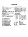
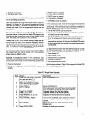
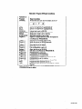
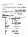
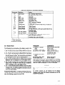
SPECIFICATIONS
GENERAL
IEEE-488 BUS IMPLEMENTATION:
DISPLAY: Seven 0.5” LED digits with decimal point, function and
IEEE status annunciators.
INTERNAL CLOCK: Displays hours/minutes/seconds
or date/
month; less than 1 minute/month error (typical).
BATTERY BACKUP: Rechargeable 3.6V nickel-cadmium. I month
retention of data with unit turned off.
OPERATING ENVIRONMENT:
O” to 50°C, 0% to 80% relative
humidity up to 35OC.
STORAGE ENVIRONMENT:
-25OC to 65OC.
CONNECTORS;
Four BNC (lTL compatible): External Trigger,
Alarm Out/Serial-In, Channel Ready, Serial Out.
CAPACITY: Ten plug-in cards per mainframe.
EXPANSION CAPACITY: Daisy chain allows up to 4 SLAVE units
with I MASTER unit.
SWITCHING RATE: 100 channels/second (IOmsl, programmable
to 1 channel/l6 minutes (999.999s).
RELAY DRIVE: 4A minimum.
POWER: 90-125V or 195250V (internally selected), 50Hz to 400H2,
75V.A maximum.
DIMENSIONS, WEIGHT: 178mm high x 438mm wide x 448mm
deep (7” x 17 l/4” x 17 3/8”). Net weight 8.6kg (19 Ibs).
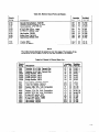
ACCESSORIES AVAILABLE:
Multiline Commands:
DCL, LLO, SDC, GET, GTL, UNT, UNL,
SPE, SPD.
Uniline Commands: IFC, REN, EOI, SRQ, ATN.
Interface Functions: SHI, AHI, T6, TM, L4, LEO, SRI, RLI, PPO,
DCI, DTI, CO, El.
Programmable
Parameters: Display Mode, Output Format, EOI,
SRQ, Fir&Last, Open, Close, Display Channel, Alternate Output,
Pole Mode, Date Format, Save/Recall, Reset, I/O Port, Time,
Date, Settle Time, Interval Time, Alarm Time, Program Mode,
Trigger Mode, Terminator, Self Test.
Digital I/O Port: A separate edge connector consisting of eight
input and eight output lines as well as common and + R/DC. Outputs will drive one lTL load. Inputs represent one lTL load.
Mating connector supplied.
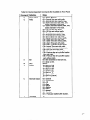
FRONT PANEL PROGRAMS
- Digital I/O
I* - Date Format
0
2* - Settle
Time
3* - IEEE Address
Model
Model
Model
Model
Model
Model
Model
Model
Model
Model
Model
Model
Model
Model
Model
Model
Model
Model
7008-3: IEEE-488 Cable, 0.9m (3 ft.)
70086: IEEE-488 Cable, 1.8m (6 ft.)
7010: IEEE-488 Adapter for Model 85 Computer.
7024-I: Triaxial Cable, 0.3m (I ft.)
7024-3: Triaxial Cable, 0.9m (3 ft.)
7024IO:Triaxial Cable, 3.0m (IO ft.1
7051-2: BNC to BNC Cable, 0.6m (2 ft.)
7051-5: BNC to BNC Cable, 1.5m (5 ft.)
7052: 4 x 5 Matrix Card
7053: High Current Scanner Card
7054: High Voltage Scanner Card
7056: General Purpose Scanner Card
7057A: Thermocouple Scanner Card
7058: Low Current Scanner Card
7059: Low Voltage Scanner Card
7061: Universal Interface Card
7068: Fixed Rack Mounting Kit for 706
7069: Slide Rack Mounting Kit for 706
Speclfi+lons
subject to change without notice.
4* - Save Setup
5* - Recall Setup
6* - Poles
7
8
go*
91,
92*
93
94
99
- Alarm
-
Time
Self Test
Stand Alone
Master
Slave
Inspect
Clear
Reset
*Battery
backed up.
Read or change state on digital I/O port.
Changes date display between MM.DD
and DD.MM.
Time to output CHANNEL READY pulse
after closing relay.
Set bus address; not programmable from
bus.
Stores present relay setup in buffers l-75.
Recalls relay setup in buffers l-75.
1, 2, or Qpole configuration for scanning
(I-pole requires 7056). O-pole for matrix
card.
Set time for Alarm output pulse; repeats
daily.
Check RAM, ROM, LEDs.
Single 706 configuration.
Daisy Chain configuration.
Daisy Chain configuration.
Display closed relays only.
Clear buffer location.
Reset battery backup parameters to factory values.
Safety Precautions
The following safety precautionsshould be observedbefore using
this product and any associatedinstrumentation.Although someinstruments and accessorieswould normally be used with non-hazardous voltages, there are situations where hazardousconditions
may be present.
This product is intended for use by qualified personnelwho recognize shock hazardsand are familiar with the safety precautionsrequired to avoid possible injury. Read the operating information
carefully before using the product.
Exercise extreme caution when a shock hazard is present.Lethal
voltage may be present on cable connectorjacks or test fixtures.
The American National StandardsInstitute (ANSI) states that a
shock hazard exists when voltage levels greater than 30V RMS,
42.4V peak,or 60VDC are present.A good safety practice is to expect that hazardous voltage is present in any unknown circuit
before measuring.
Before operating an instrument, makesurethe line cord is connected to a properly grounded power receptacle.Inspect the connecting
cables, test leads, and jumpers for possiblewear, cracks,or breaks
before each use.
For maximum safety, do not touch the product, test cables,or any
other instruments while power is applied to the circuit under test.
ALWAYS remove power from the entire test systemand discharge
any capacitorsbefore: connecting or disconnectingcablesor jumpers, installing or removing switching cards, or making internal
changes,such as installing or removingjumpers.
Do not touch any object that could provide a current path to the
common side of the circuit under testor power line (earth) ground.
Always make measurementswith dry hands while standing on a
dry, insulated surface capable of withstanding the voltage being
measured.
Do not exceed the maximum signal levels of the instruments and
accessories,asdefined in the specifications and operating information, and as shown on the instrument or test fixture panels, or
switching card.
Do not connectswitching cardsdirectly to unlimited power circuits.
They are intended to be used with impedance limited sources.
NEVER connect switching cards directly to AC main. When connecting sourcesto switching cards,install protective devices to limit fault current and voltage to the card.
When fusesareusedin a product,replacewith sametype and rating
for continued protection against fire hazard.
Chassis connections must only be used as shield connections for
measuringcircuits, NOT as safety earth ground connections.
If you are using a test fixture, keepthe lid closed while power is applied to the device under test. Safe operation requires the use of a
lid interlock.
Ifa @ screw is present,connect it to safety earth ground using
#18 AWG or larger wire.
The t symbol on an instrumentor accessoryindicates that 1OOOV
or more may be presenton the terminals. Referto the productmanual for detailed operating information.
Instrumentation and accessoriesshould not be connected to humans.
Maintenance should be performed by qualified service personnel.
Before performing any maintenance;disconnect the line cord and
all test cables.
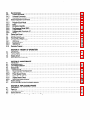
TABLE OF CONTENTS
Title
Paragraph
SECTION l-GENERAL
INFORMATION
Introduction ...................................................................................
1.1
Model 706 Features .............................................................................
1.2
Warranty information. ...........................................................................
1.3
Manual Addenda ...............................................................................
1.4
Safety Symbols and Terms .......................................................................
Unpacking and Inspection ........................................................................
E
...................................
Specifications.............................................;.1:7
Optional Accessories ............................................................................
1.8
.........................................................................
Repackingforshipment
1.9
E
2:9
2.9.1
2.9.2
2.9.3
2.9.4
2.9.5
2.9.6
2.9.7
2.9.8
2.9.9
2.9.10
2.9.11
2.9.12
2.9.13
2.9.14
2.9.15
SECTION 2-OPERATION
Introduction ...................................................................................
PreparationforUse ..............................................................................
CorrectLineVoltage ...........................................................................
Plug-In Card (Scanner) Installation ...............................................................
PowerUp .....................................................................................
Environmental Condition .........................................................................
...........................................................................
Operatinglnstructions
FrontPanelControls ...........................................................................
Rear Panel Description. ........................................................................
Basic Front Panel Operation ....................................................................
ScanningExamples ...........................................................................
Front Panel Clock Operation .....................................................................
Detailed Front Panel Controls Description ..........................................................
..................................................................
DetailedRearPanelDescription
Front Panel Programs. ..........................................................................
Program 0 Digital I/O .........................................................................
Program 1 Data Format .......................................................................
Program 2 Relay Settle Time ...................................................................
Program 3 Set IEEE Primary Address ...........................................................
Program 4 Save Relay Set Up ..................................................................
Program 5 Recall Relay Set Up .................................................................
Program 6 Pole Configuration, Matrix Mode .......................................................
Program 7 Set Alarm Time ....................................................................
Program 8 Diagnostic Self Test. ................................................................
Program 90 Stand Alone ......................................................................
Program 91 Master. ..........................................................................
Program92Slave ............................................................................
Program 93 Inspect .........................................................................
Program 94 Clear ............................................................................
Program 99 Reset ............................................................................
3.1
3.1.1
3.1.2
3.1.3
3.1.4
3.2
3.2.1
3.2.2
3.2.3
3.3
SECTION 3-IEEE BUS OPERATION
Introduction ...................................................................................
Software Consideration ........................................................................
......................................................................
HP-85BASlCStatements
Interface Function Codes. ......................................................................
Mode 706 Interface Commands .................................................................
IEEE488 Bus Lines ..............................................................................
Bus Management Lines ........................................................................
Handshake Lines .............................................................................
Data Lines ...................................................................................
System Set Up Procedure ........................................................................
;-:
2:2.1
2.2.2
2.3
z.2
2:5.1
2.5.2
2.5.3
2.5.4
2.6
Page
l-l
l-l
l-l
l-l
l-l
l-l
l-l
l-2
1-3
2-1
2-l
2-l
2-l
2-2
2-3
2-3
2-3
2-3
2-7
2-8
2-13
2-14
2-17
2-18
2-19
2-19
2-20
2-20
2-21
2-21
2-22
2-24
2-25
2-25
2-25
2-26
2-26
2-27
2-28
3-l
3-l
3-l
3-2
3-3
3-3
ifi
3-4
3-4
i
;*i 1
31412
3.4.3
3.5
3.5.1
3.5.2
3.5.3
3.5.4
3.5.5
3.5.6
3.5.7
3.58
3.6
3.7
3.8
3.9
3.9.1
3.9.2
3.9.3
3.10
Bus Commands ................................................................................
Uniline Commands ............................................................................
Universal Commands ..........................................................................
Addressed Commands .........................................................................
Device-Dependent Commands ....................................................................
DisplayMode ...............................................................................
......................................................................
Program(Scan)Mode..
Prefix.. ....................................................................................
..........................................................................
EOI(EndorIdentify)
....................................................................
BusResponseMode(SRQ)
TriggerModes ...............................................................................
Programmable Terminator (Y) ..................................................................
.................................
Inputs....................................................-.
.............................................................................
StatusByteFomat
Status Word (U) ...............................................................................
Front Panel Programs ..........................................................................
......................................................................
FrontPanelErrorMessages
IDDCError ..................................................................................
No Remote Error. ............................................................................
IDDCOError ................................................................................
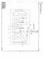
ScanningProgram .............................................................................
f.2
SECTION 4-THEORY
OF OPERATION
Introduction ...................................................................................
PowerSupply ..................................................................................
Microcomputer .................................................................................
DisplayCircuit ..................................................................................
.......................................................................
IEEE-488lnterfaceCircuitry
5.1
5.2
5.3
5.4
5.5
5.5.1
5.5.2
5.5.3
5.5.4
5.5.5
5.5.6
5.6
5.7
SECTION 5-MAINTENANCE
Introduction ...................................................................................
FuseReplacement ..............................................................................
...........................................................................
LineVoltageSelection
Disassembly ...................................................................................
Troubleshooting ................................................................................
.................................................................
RecommendedTestEquipment
DigitalSelfTest ...............................................................................
.........................................................................
PowerSupplyChecks
........................................................................
DigitalCircuitryChecks
T...........................................................
Display Boards Check .............
.....................................................................
InterconnectBoardChecks
BatteryCharge .................................................................................
Special Handling of Static Sensistive Devices ........................................................
6.1
6.2
6.3
6.4
6.5
SECTION 6-REPLACEABLE
PARTS
Introduction ...................................................................................
Pa&List ......................................................................................
..........................................................................
Orderinglnformation..
Factory Service. ................................................................................
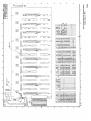
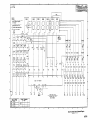
Component Location Drawings and Schematic Diagrams ..............................................
4.1
4.2
4.3
;1;
331:
3-14
3-15
3-16
3-16
318
3-18
3-19
3-27
3-28
3-29
3-29
3-29
3-29
3-29
3-29
4-1
4-l
4-l
4-3
4-3
5-l
5-l
5-1
5-3
5-6
5-6
5-6
5-7
5-7
5-7
z
5-8
6-l
6-l
6-l
6-l
6-1
LIST OF FIGURES
Figure
1-I
;::
;:“4
2-5
;:y
3-2
3-3
$2
3-6
g;:
3-9
4-1
2::
2::
6-l
6-2
6-3
6-4
6-5
6-6
6-7
6-8
Title
Model706Scanner ..................................................................
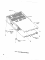
Scanner Card Installation .............................................................
FrontPanelControl ..................................................................
...............................................................
Model706RearPanel
Daisy Chain Configuration ............................................................
...........................................................
Model7052MatrixScheme
Matrix Display Clarification ............................................................
BusStructure ......................................................................
HandshakeSequence ................................................................
ContactAssi nments ................................................................
TypicalBus 8 onnector ...............................................................
Digital I/O Port Pin Assignment .........................................................
.............................................................
UandGModeSequence
StatusByte Format ..................................................................
Status Word Format .................................................................
IEEE Display Error Messages ..........................................................
.............................................................
Model706BlockDiagram
..............................................................
Model706MemoryMap
Topand BottomCoverRemoval ........................................................
PowerSup IyExplodedView ..........................................................
.:. .:. .. I .. .‘. .. lI. .~.._‘.... _. ..............................
Model706 L1opView .........
Display Board, Component Location Drawing, Dwg. No. 706-l 10 ..............................
Digital I/O Board, Component Location Drawmg, Dwg. No. 706-170 ............................
Mother Board, Component Location Drawing, Dwg. No. 706-I 10 ...........................
Interconnect Board, Component Location Drawing, Dwg. No. 706-I 60 .......................
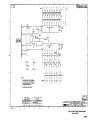
Display Board, Schematic Diagram, Dwg. No. 705-l 16 ...................................
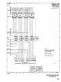
Digital I/O Board, Schematic Diagram, Dwg. No. 706-176 .................................
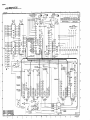
Mother Board, Schematic Diagram, Dwg. No. 706-I 06 ...................................
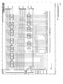
Interconnect Board, Schematic Diagram, Dwg. No. 706-l 66 ...............................
Page
1-o
;:$I
22;7
2-23
2-24
;:;
3-5
3-5
3-24
3-27
3-28
3-28
3-29
z
5-2
5-4
5-5
6-9
6-10
6-I 1/6-l 2
6-l 5/6-i 6
6-17/6-18
6-19/6-20
6-21/6-22
6-25/6-26
LIST OF TABLES
Table
2-1
2-2
2-3
2-4
2-5
2-6
2-7
2-8
2-9
2-10
2-11
2-12
2-13
2-14
2-l 5
2-l 6
2-17
2-l 8
2-19
Title
.................................................................
LineVoltageSetting
Slot Number/Channel Number Assignment ...............................................
Power Up Default Conditions (Front Panel Operation) .......................................
Front Panel Controls .................................................................
Rear Panel Description ...............................................................
StepScanExample ..................................................................
................................................................
SingleScanExample
............................................................
ContinuousScanExample
Required Equipment for Daisy Chain Example .............................................
Daisy Chain Example ................................................................
Temperature Scan Example ...........................................................
Low Current Scan Example ...........................................................
SettingtheTime ....................................................................
....................................................................
SettingtheDate
Maximum Relay Drive Current from Mainframe ............................................
CANCEL Function Example ...........................................................
Summary of Front Panel Programs ......................................................
.,....................................
Scanner Card Pole Configuration ..................
Matrix Unit Number Display Assignment ..................................................
Page
2-1
2-l
g:;
2-7
;:g
2-10
2-l 0
2-l 1
12-12
2-13
2-l 3
2-14
2-15
2-16
2-19
2-22
2-24
Iii
LIST OF TABLES (CONT.)
2-20
2-21
3-l
3-2
3-3
34
3-5
3-6
3-7
3-8
3-9
3-10
5-l
5-2
5-3
54
5-5
5-6
5-7
5-8
5-9
6-l
6-2
6-3
6-4
6-5
6-6
6-7
Iv
Matrix Card Number Display Assignment ............................................................
Program 99 Reset Condition .......................................................................
HP-85 IEEE-488 BASIC Statements ..................................................................
Model 706 Interface Function Codes .................................................................
IEEECommand Groups ............................................................................
IEEE Bus Connector Contact Designations ............................................................
Power Up, DCL and SDC Default Conditions ..........................................................
Device-Dependent Commands Not Available to the Front Panel ..........................................
Model 706 Device-Dependent Commands ...........................................................
Hierarchy of Command Execution ..................................................................
SRQ Commands and Conditions ...................................................................
Digital I/O Port Contact Pin Assignments ............................................................
Fuse Replacement 3AG Size. .......................................................................
Fuse Replacement 5mm Size .......................................................................
Line Voltage Selection. ............................................................................
RecommendedTestEquipment
.....................................................................
.............................................................................
PowerSupplyChecks
DigitalCircuitn/Checks
............................................................................
DisplayBoardChecks
.............................................................................
.........................................................................
InterconnectBoardChecks
Model 706 Static Sensitive Devices ..................................................................
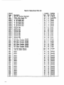
Model 706 Recommended Spare Parts List. ...........................................................
Index of Model 706 Schematics and Component Layouts. ...............................................
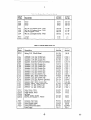
Display Board Parts List ...........................................................................
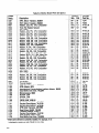
Mother Board Parts List ...........................................................................
Digital I/O Board Parts List .........................................................................
Interconnect Board Parts List .......................................................................
Model 706 Mechanical Parts List ....................................................................
2-24
2-29
3-2
3-3
3-3
3-5
3-6
3-9
3-10
3-12
3-16
3-24
5-l
5-l
5-l
5-6
5-6
5-7
5-7
5-8
5-8
6-l
6-l
6-2
6-3
6-5
6-6
6-7
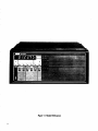
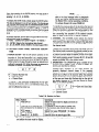
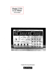
Figure l-l.
1-O
Model 706 Scanner
SECTION 1
GENERAL INFORMATION
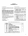
1.1 INTRODUCTION
The Model 706 is an IEEE488 bus compatible scanner that
can accommodate ten plug-in scanner cards. With ten scanner cards installed up to 100 2-pole channels can be on the
same IEEE address. Using four additional Model 706s in a
daisy chain configuration up to 500 2-pole channels can be
on the same IEEE address. The Model 706 scanner adheres to
standard IEEE488 interface bus protocol. This enables the
Model 706 to be incorporated into any measurement that
uses programmed control through the IEEE-488 bus.
The front panel controls are clearly marked and easy to use.
These controls serve several functions such as opening a
selected channel, closing the channel, scanning between a
selectable first and last channel, selecting scan rate and
mode. There are 15 internal programs that are accessible
from the front panel. The programs can select primary address, settling time, store a relay set up, recall the stored relay
set up, control the digital I/O port, switch from International
to American date format, start or stop a scan sequence,
select 1, 2 or 4-pole measurement modes and program the
Model 706 as a master, slave or stand alone instrument in a
daisy chain configuration. The Model 706 may also be
operated in a matrix configuration.
The time and date are kept internally with a battery backed up
clock allowing time dependent procedures to be performed.
1.2 MODEL 706 FEATURES
The Model 766 scanner includes the following features:
.lJp to 100 2-pole channels.
aIEEE-488 bus operation.
*Selectable scan rate of IOmsec to 999.999sec.
aSelectable scan modes that enable the user to scan the first
channel to the last channel once, continuously or manually.
*Fifteen internal programs that are accessible from the front
panel.
aModel 706 mainframe can accomodate 10 scanner plug-in
cards.
*Several different plug-in scanner cards are available as options. They include: a general purpose relay card, a thermocouple card, low voltage card, low current card, high
current card, high voltage card, matrix card and universal interface card.
*Time and date are kept with a battery backed up clock.
*Digital I/O port with eight lines as inputs and eight lines as
outputs.
*External trigger input that accepts a greater than wet
negative going TTL compatible pulse for triggering the
Model 706 into a scan sequence.
@Channel ready output that outputs a greater than IOFec
negative going lTL compatible pulse upon the completion
of the programmed channel settling time.
*Alarm output that outputs a negative going lTL level
greater than 10,usec pulse when the programmed time is
reached.
1.3 WARRANTY
INFORMATION
Warranty information is provided on the inside front cover of
this manual. If there is a need to exercise the warranty, contact your Keithley representative in your area to determine the
proper action to be taken. Keithley maintains complete repair
and calibration facilities in the United States, West Germany,
Great Britain, France, the Netherlands, Switzerland and
Austria. Information may be directed to the applications
engineer at any of the above locations. Check the inside front
cover of this manual for addresses.
1.4 MANUAL
ADDENDA
Improvements or changes to this manual will be explained on
an addendum included with this manual.
1.5 SAFETY SYMBOLS
AND TERMS
Safety symbols used in this manual are as follows:
on the instrument denotes that the user
The symbol Q ’
should refer to the operating instructions.
on the instrument denotes that high
The symbol AM
voltage may be present on the terminals.
The, WARNING used in this manual explains dangers that
could result in personal injury or death.
The CAUTION used in this manual explains hazards that
could damage the instrument.
1.6 UNPACKING
AND INSPECTION
The Model 706 is inspected both electrically and mechanically
before shipment. Upon receiving the Model 706, unpack all
items from the shipping container and check for any obvious
damage that may have occurred during transit. Report any
damage to the shipping agent. Retain and use the original
packaging materials if reshipment is necessary. The following
items are shipped with all Model 706 orders:
*Model 706 Scanner
*Model 706 Instruction Manual
*Optional accessories per request. (Cards are shipped
separately. 1
1.7 SPECIFICATIONS
For Model 706 detailed specifications,
tions that precede this section.
refer to the specifica-
1-l
+
1.8 OPTIONAL
ACCESSORIES
Switching Cards switching cards. In
matrix applications,
with signal handling
Model 7051-2 1 The Model 7051-2 is a (2 feet) BNC to BNC
cable. It is especially useful for daisy chain operation.
Keithley offers over 20 different models of
addition to general purpose scanning and
cards are designed for special applications
capabilities that include:
Low voltage switching to 20nV.
Low current switching to 1OfA.
l
High frequency switching to 500MHz.
o Thermocouple switching with a precision temperature
ence.
l
High voltage switching to 1OOOV.
Model 7051-5 - The Model 7051-5 is a (5 feet) BNC to BNC
cable. It is especially useful daisy chain configuration.
Model 7068 Fixed Rack Mount-The
Model 7068 is a fixed or
stationary rack mounting kit that mounts the Model 706 in a
standard 19 inch rack. The dimensions are 13-3/4 inches deep
x 7 inches high (350mm x 178mm).
l
l
refer-
Model 7069 Slide Rack Mount with Handles - The Model
7069 is a sliding rack mount kit. It enables one Model 706 to be
rack mounted with the added feature of sliding the instrument
for easy access. The dimensions are 3-3/4 inches deep x 7
inches high (95mm x 178mm).
Further details on switching cards can be obtained by contacting a Keithley representative or sales office.
1.9 REPACKING
The Model 706 should be packed in its original carton. Before
packing, wrap the instrument in plastic. After it is placed in the
box, surround the instrument with Styrofoam packaging material. Remove all cards and ship separate.
Model 7008-3 IEEE-488 Cable-The
Model 7008-3 is a 1 meter (3 feet) IEEE-488 cable. The cable has 24 stranded wire
conductors and is terminated on each end with IEEE-488 standard connectors.
If the Model 706 is to be returned to Keithley Instruments
calibration or repair, include the following:
Model 7008-6 IEEE-488 Cable-The
Model 7008-6 is a 2 meter (6 feet) IEEE-488 cable. The cable has 24 stranded wire
conductors and is terminated on each end with IEEE-488 standard connectors.
for
Write ATTENTION REPAIR DEPARTMENT on the address
label.
= Include the warranty status of the instrument.
l
Photocopy and complete the service form at the back of this
manual and return it with the instrument.
l
Model 7010 Cable Adapter-The
Model 7010 is an IEEE-488
cable adapter. The adapter extends the IEEE-488 connector by
one connector width.
1-2
FOR SHIPMENT
+
SECTION 2
OPERATION
2.1 INTRODUCTION
Operation of the Model 706 is divided into two sections: front
panel operation and IEEE-488 bus operation. IEEE bus operation is located in Section 3. This section contains the following information:
*Preparation for use
@Power Up
iEnvironmental Conditions
*Front and Rear Panels Description
@Examples of Scanning
aFront Panel Programs
2.2 PREPARATION
2.2.1 Correct
FOR USE
Line Voltage
Connect the Model 706 to the proper power receptacle (refer
to Table 2-l). For fuse replacement or line voltage setting
refer to Section 5 Maintenance.
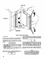
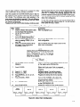
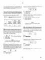
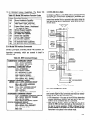
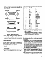
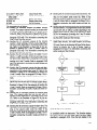
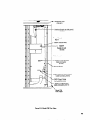
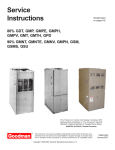
1. To install a scanner card, slide the card into the appropriate
vertical slot. The slots are numbered 1 through 10. Refer to
Table 2-2 for slot number/ channel numbers assignment.
Facing the rear panel of the Model 706, the scanner card
component side should face the left side of the slot. Make
certain the card edges are aligned with the top and bottom
grooves in the slot.
2. Once the card is aligned with the grooves, insert the card
to its full depth into the Model 706. Make certain the card
is properly seated into the connector on the interconnect
board. When the card is fully inserted, the locking tabs on
the card should be placed in the locked position as shown
in Figure 2-1.
3. To remove a scanner card, first turn the Model 706 off and
disconnect the line cord. Unfasten the locking tabs by pulling both tabs outward. Grasp the end of the card and pull it
out of the mainframe.
NOTE
Handle the scanner cards by the edges to avoid
contaminating them with dirt, body oil, etc.
WARNING
Ground the instrument
through a properly
earth grounded
receptacle
before operation. Failure to ground the instrument can
result in severe injury or death in the event
of a short circuit or malfunction.
2.2.2 Plug-In
Card (Scanner)
Installation
WARNING
Do not insert scanner cards that have metal
clamps into the Model 706. Otherwise
a
shock hazard will be present. Only use
scanner cards that have plastic clamps.
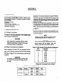
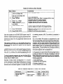
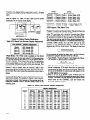
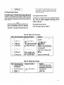
Table 2-2. Slot Number
Channel
Number
Assignment
Slot
Number
1
2
3
4
5
Channels
Before operating the Model 706, the appropriate scanner
Included
cards must be installed into the mainframe. Each scanner
l-10
card (up to 10 cards per the Model 706 mainframejis installed
11-20
in-the appropriate vertical slot in the rear panel of the Model
2130
706. Refer to Figure 2-l for an overall picture of scanner card
31-40
installation.
41-50
51-60
WARNING
7”
61-70
To prevent a possible shock hazard, turn
71-60
the instrument
off and disconnect the line
ii
81-90
cord before installing/removing
any scan10
91-100
ner card.
“Does not include other units in a daisy cha;
configuration see paragraph 2.5.4 example 4.
Table 2-l. Line Voltage Setting
Input
Voltage
9OV-125v
Jumper
Setting
Installed
195v-250v
Not
Installed
I Line Fuse
3AG
1.25A,
250V
0.6A,
250V
FlOl . Varistor
VR2
5mm
1.25A, installed
250V
0.6A,
not
250V
installed
2-l
LOCKING
TABS
NDLES
MODEL706
/
REAR PANEL
SCANNER CARD
INSTALLATION
Figure 2-l. Scanner
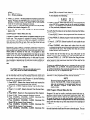
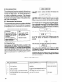
2.3 POWER UP
When the Model 706 is turned on the instrument goes
through a power up sequence that is outlined as follows:
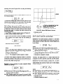
Immediately after turing on the Model 706 via the power
switch, the display indicates the following for a number of
seconds:
1
1
1. This is a display test. The operator can note inoperative
display segments by comparing the Model 706’s display
with the figure above.
2. In addition, the pushbutton and the TALK, LISTEN and
REMOTE indicators turn on. All indicators turn on
simultaneously if operating correctly.
After the display test is complete, the Model 706 displays the
software revision level for approximately 0.5 seconds. The
following is an example of software revision level Al.
RI
‘2-2
I
Card Installation
After the software revision level is displayed, the Model 706
displays the primary address of the instrument for approximately 0.5 seconds. The primary address of the Model 706 is
factory set at 18.
r---r-q
During the display test the Model 706 performs a digital self
test of the RAM circuitry and a cyclic redundancy check
(CRC) of the ROM circuitry. If a problem is found by these
tests the Model 706 displays a diagnostic number. This
number and its meaning is described in detail in Section 5.
After all the displays and test of the power up sequence, the
Model 706 comes to the default conditions that are listed in
Table 2-3.
NOTE
If upon power up the Model 706 displays the
slave or no loop message (refer to paragraphs
2.9.11 and 2.9.12) activate Program 90 to return
the Model 706 to normal operating conditions.
To activate Program 90, press PRGM, 9, 0.
Table 2-3. Power Up Default
Conditions
(Front Panel Operation)
Function or
Default Conditions
Program
Channel mode is selected, channel 1 is displayed and all channels are open.*
CHANNEL
TIME
Time is not affected by power up.
Date is not affected by power up.
DATE
Reset is not affected by power up.
RESET
Interval time is not affected by power up.
INTERVAL
Single scan mode is set to inactive.
SINGLE
CONTINUOUS
Continuous scan mode is set to inactive.
Start/Stop function is set to stop.
START/STOP
Digital I/O outputs are set to 000, the inputs are not affected by power up.
Program 0
Date format is not affected by power up.
Program 1
Program 2
Settle time is not affected by power up.
Primary address is not affected by power up. ..
Program 3
Program 4
Save relay set up is cleared from display but still in memory. Channel 1 is displayed.
Recall relay set up is cleared from display but still in memory. Channel 1 is displayed.
Program 5
Program 6
Number of poles is not affected by power up.
Program 7
Alarm time is set to 00.00.00.
Program 8
Self test is not activated.
Program 90 is not affected by power up.
Program 90
Program 91 is not affected by power up.
Program 91
Program 92
Program 92 is not affected by power up.
Program 93 is set to inactive.
Program 93
Program 94 is not affected by power up.
Program 94
Program 99 is not affected by power up.
Program 99
The first function is not affected by power up.
FIRST
The last function is not affected by power up.
LAST
All channels are open.
CLOSE
All channels are open.
OPEN
*If channel 1 was previously programmed as the first channel, last channel, both or neither, it is displayed as such.
The FIRST and LAST functions are not affected by power up.
To identify the previous state of the functions that are not affected by power up simply activate the desired function.
When the function is activated the previous state for that
function is displayed. Refer to paragraph 2.5.1 for information concerning the actuation of the desired function.
2.4 ENVIRONMENTAL
CONDITIONS
All operation of the Model 706 should take place at an ambient temperature within the range of O°C to 50°C, up to
35OC at 80% noncondensing relative humidity. Environmental conditions for storage are -25OC to +65OC.
NOTE
If the Model 706 internal operating temperature
is higher than 75OC the thermal breaker on the
power supply will open up. This action will shut
down the Model 706. Refer to Section 5
paragraph 5.5.3.
2.5 OPERATING
INSTRUCTIONS
2.5.1 Front Panel Controls
Table 2-4 lists all the front panel controls and buttons. Their
operation and function are briefly described in the table. For
complete details concerning the front panel controls refer to
paragraph 2.7. Refer to Figure 2-2 for a view of the front
panel controls.
2.5.2 Rear Panel Description
Table 2-5 lists all the rear panel connectors and terminals.
Their function and operation are briefly described in the table.
For complete details concerning the rear panel refer to
paragraph 2.8. Refer to Figure 2-3 for a view of the Model 706
rear panel.
2-3
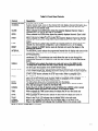
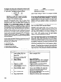
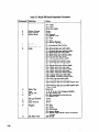
Table 2-4. Front Panel Controls
Control
POWER ON/OFF
CHANNEL
Description
Turns the unit on or off.
Selects channel mode, turns on the channel LED and displays channel information (e.g.
open or closed, first or last). Increments channel number by one each time it is activated when in the channel mode.
CLOSE
When activated the CLOSE button closes the presently displayed channel. Close is
indicated by a c on the far right digit of the display.
OPEN
When activated the OPEN button opens the presently displayed channel. Open is indicated by an o on the far right digit of the display.
When activated the FIRST button specifies the presently displayed channel as the first
FIRST
channel of a multi channel configuration. First is indicated by an F in the middle of the
Idisplay.
When activated the LAST button specifies the presently displayed channel as the last
LAST
channel of a multi channel configuration. Last is indicated by an L on the display.
When activated the RESET button opens all channels and reverts the display to the
RESET
specified first channel.
INTERVAL
The INTERVAL button selects the programmed interval time for display and turns on the
interval LED. The interval time is the programmed time each channel is closed in a
scanning sequence.
CONTINUOUS
The CONTINUOUS button selects the continuous scan mode and turns on the
continuous LED. The continuous scan mode allows the user to scan through the
programmed channels in a continuous cycle upon the actuation of the START/STOP
button.
The SINGLE button selects the single scan mode and turns on the SINGLE LED.
SINGLE
The single scan mode allows the user to scan through the programmed channels
one time upon the actuation of the START/STOP button.
The START/STOP button when activated initiates the selected scan mode and turns
START/STOP
on the START/STOP LED. Pressing the button during a scan stops the scan sequence
and turns off the START/STOP LED. When not in the continuous or single scan modes the
START/STOP button activates the STEP scan mode. Refer to paragraph 2.5.4.
The PRGM (Program) button when activated shows a display that prompts the user to
PRGM
select one of the 15 front panel programs. Refer to paragraph 2.9 for complete
details and examples of the front panel’programs.
The O-9 buttons allow entry of numerical data onto the display.
DATA
The ENTER button loads the displayed data for the interval time, channel number,
ENTER
time, date and program modes into the Model 706.
During the entry of data (C segment cursor is flashing) the CANCEL button cancels
CANCEL
the present display and reverts the instrument to the previous display.
TIME
When activated the TIME button selects for display the 24 hour time clock and
turns on TIME LED.
DATE
When activated the DATE button selects the date mode for display and turns on
the DATE LED.
When lit the TALK LED indicates that the Model 706 is in the talk mode.
TALK”
When lit the LISTEN LED indicates that the Model 706 is in the listen mode.
LISTEN*
When lit the REMOTE LED indicates that the Model 706 is in the remote mode.
REMOTE*
*Refer to Section 3 IEEE-488 bus operation.
.2-G:
I
I .
I
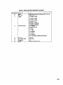
Table 2-5. Rear Panel Deswiption
Connections
Card Slots
SER. OUT
ALARM/SERIAL
Description
Each slot accepts one scanner card. There are a total of 10 slots.
The serial output connector is a female BNC connector that provides
connection to another Model 706 for a daisy chain configuration.
The alarm function of this female BNC connector outputs a pulse when the
programmed alarm time is reached. The serial in function is used in a
daisy chain configuration where serial in is connected to the serial out of
another Model 706.
This female BNC connector outputs a pulse at the completion of the programmed channel settling time.
This is a female BNC connector that initiates the selected scan mode upon
receiving the proper signal pulse.
The digital I/O port consists of 16 digital input/output lines along with four
lines that are +5V and IEEE common.
This standard connector provides connection to the IEEE-488 bus.
IN
CHANNEL READY
EXT. TRIGGER
DIGITAL I/O
IEEE-488 INTERFACE
CONNECTOR
FUSE
The line power fuse provides protection for the AC power line input and is
rated as shown in Table 2-l.
The line power receptacle mates with three wire line cord and applies the
line power to the instrument.
AC Power Receptacle
2.5.3 Basic Front Panel Operation
This section provides the information necessary for basic
front panel operation of the Model 706. There are a number
of steps to follow in order to get the Model 706 ready for
scanning operation. These steps are as follows:
1. Install the desired scanner card(s). Refer to paragraph 2.2.2
for information concerning the installation of the scanner
cards into the Model 706.
2. Select appropriate line voltage. Refer to Section 5
Maintenance for information concerning the selection of
appropriate line voltage and proper fuse rating.
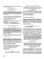
3. Turn on the Model 706. The instrument then goes through
the power up sequence that is described in paragraph 2.3
and displays one of the following:
I[
(Normal Condition)
I o
(Matrix Mode Refer to
1 Paragraph 2 .9 .71
NOTE
If upon power up the Model 706 displays the
slave or no loop message (refer to paragraphs
2.9.11 and 2.9.12) activate Program 90 to return
the Model 706 to normal operating conditions.
To activate Program 90, press PRGM, 9, 0.
NOTE
Channel 1 is set as the programmed first channel. If another channel was previously programmed as the first or last channel, then the F or L
will not be displayed upon power up.
4. Program the desired channel. (Channel mode is selected
upon power up).
A. Select the first channel.
1. Press the desired channel number from the DATA
group buttons O-9.
2. Press the FIRST button to program the presently
displayed channel as the first channel.
NOTE
Selecting a channel that does not exist in the
present set up causes the Model 706 to display
the following message.
no
Ch
B: Select the last channel.
1. Press the desired number from the DATA group button O-9.
2. Press the LAST button to program the presently
dispkyed channel as the last channel.
5. Program the number of poles (0, 1, 2 or 4).
A. Press PRGM.
B. Press 6.
C. Select number of poles (0, 1, 2 or 4).
D. Press ENTER.
NOTE
The 0 pole mode is the matrix mode. Refer to
paragraph 2.9.7 for complete details concerning
programming of the different poles.
6. Program the interval time.
A. Press the INTERVAL button to select interval mode for
display.
B. Enter the interval time on the display by pressing from
the DATA group the desired time, within the limits of
000.010 to 999.999 seconds.
C. Press the ENTER button.
7. Program the desired scan mode. Press the SINGLE or
CONTINUOUS button to select one of these two scanning
modes. To select the step scan mode press the CHANNEL
button.
8. Press the START/STOP button to start the scanning sequence. For the step mode press the START/STOP button each time a single channel is to be scanned.
The previous steps 1 through 8, show a general procedure to
-get the Model 706 into a scanning sequence. Paragraph 2.5.4
shows how to use the different scan modes, how to daisy
chain several Model 706s for an extended number of channels and how to scan using different scanner cards.
2.5.4 Scanning
Examples
Example 1 Manual Scan (Step Scan&If
it is desired to
scan through the programmed channels manually the Model
706 can be programmed for the step scan mode. In the step
scan mode the programmed channels can be scanned (closed
for the programmed interval rate and then opened) one channel at a time. Upon the actuation of the START/STOP button a single channel will be scanned. For this example we will
choose the following parameters.
1. First channel is 1.
2. Last channel is 10.
3. Interval time is 2 seconds.
4. Number of poles is 2.
5. Use the step scan mode.
Use the steps outlined in Table 2-6 to program the Model 706
for the preceding parameters. For the sake of simplicity we
will use the Model 7056 general purpose scanner card for this
example.
Upon the actuation of the START/STOP button in step 9,
channel 1 is closed and the START/STOP LED is turned on.
Channel 1 remains closed for two seconds (programmed interval rate) and then opens. The START/STOP LED turns off
and the Model 706 advances to the next channel.
To scan the remaining channels, press the START/STOP
button each time a channel is to be scanned. After the last
programmed channel is scanned the instrument reverts to the
first programmed channel and turns off the START/STOP
LED. At this point the step scan sequence may be activated
again by pressing the START/STOP button, if desired.
To stop the scanning sequence and reset the Model 706 to
the programmed first channel simply press the RESET button. .Example 2 Single Scan-In
the single scan mode all the
programmed channels are scanned sequentially one time
upon the actuation of the START/STOP button. The single
scan sequence operates as follows:
1. The START/STOP LED turns on.
2. The programmed first channel is closed for the programmed interval rate and then opened.
3. The Model 706 then advances to the next channel, closes
it for the programmed interval rate and then opens it.
4. This sequence is repeated up to and including the progammed last channel. At this point the Model 706 reverts
to the programmed first channel and turns off the
START/STOP LED.
5. The single scan sequence is now complete.
To help illustrate a single scan sequence we will choose the
following parameters. For the sake of simplicity we will use
the Model 7056 general purpose scanner card.
1. First channel is 5.
2. Last channel is 25.
3: Interval time is 0.5 seconds.
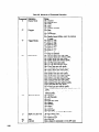
Table 2-6. Step Scan Example
Step
1
3
4
Action
Install the Model 7056 General Purpose
Scanner Card into slot 1 of the Model
706.
Select appropriate line voltage and turn
on the Model 706.
Press PRGM, 6.
Press 2, ENTER.
i
7
8
Press 0, 0, 1, FIRST.
Press, 0, 1, 0, LAST.
Press INTERVAL, 0, 0, 2,0,0,0,
Press CHANNEL, RESET.
9
Press START/STOP.
2
ENTER.
Comments
Refer to paragraph 2.2.2.
Selects PROGRAM 6.
Selects the 2-pole mode, refer to paragraph 2.9 for more information about
front panel programs.
Programs channel 1 as the first channel.
Programs channel 10 as the last channel.
Programs the interval time for two seconds.
Selects the channel mode for display and
reverts to the first channel.
Initiates the step scan mode.
.
4. Number of poles is 2.
5. Use single scan mode.
Use the steps outlined in Table 2-7 to program the Model 706
for the preceding parameters.
Upon the actuation of the START/STOP button in step 10,
channel 5 is closed for 0.5 seconds (programmed interval
rate) and then opens. The Model 706 advances to the next
channel and closes it for the programmed interval rate and
then opens it.
The sequence continues up to and including the last programmed channel. At this point the Model 706 reverts to the
programmed first channel and turns off the START/STOP
LED. The single scan sequence is now complete.
Pressing the START/STOP button during a single scan sequence stops the scan at the presently displayed channel.
The channel remains closed and turns off the START/STOP
LED. To continue the scanning sequence from the presently
displayed channel press the START/STOP button.
To stop the scanning sequence and reset the Model 706 to
the programmed first channel (which is 5 in this example)
simply press the RESET button.
Example 3 Continuous
Scan-In
the continuous scan
mode the scanning sequence described in example 2 repeats
continuously until at least one of the following conditions are
met:
1. Power is interrupted.
2. During the sequence, the START/STOP
button is
pressed.
3.
4.
5.
6.
7.
RESET button is pressed.
PRGM button is pressed.
DATE button is pressed.
TIME button is pressed.
CHANNEL button is pressed.
In the continuous scan mode all the programmed channels
are scanned sequentially and the scan sequence is repeated
continuously. The continuous scan is started by pressing the
START/STOP button and it operates as follows:
1. The START/STOP LED is turned on.
2. The programmed first channel is closed for the programmed interval rate and then opened.
3. The Model 706 then advances to the next channel, closes
it for the programmed interval rate and then opens it.
4. This sequence is repeated up to and including the programmed last channel. At this point the Model 706 reverts
to the programmed first channel and repeats the sequence
continuously.
To help illustrate a continuous scan sequence we will choose
the following parameters. For the sake of simplicity we will
use the Model 7056 general purpose scanner card.
1. First channel is 1.
2. Last channel is 100.
3. Interval time is 0.3 seconds.
4. Number of poles is 2.
5. Use continuous scan mode.
Use the steps outlined in Table 2-8 to program the Model 706
for the preceding parameters.
Table 2-7. Single Scan Example
I Comments
Ster, 1Action
Install the three Model 7056 scanRefer to paragraph 2.2.2.
1.
ner cards into slots 1, 2
* and 3 of the Model 706.
Select appropriate line voltage
2
and turn on the Model 706.
Press PRGM, 6.
Selects PROGRAM 6.
3
Press 2, ENTER.
Selects the 2-pole mode. Refer to paragraph 2.9 for
4
more information concerning front panel programs.
Press 0, 0, 5, FIRST.
Programs channel 5 as the first channel.
Press 0, 2, 5, LAST.
Programs channel 25 as the last channel.
z
Press INTERVAL, 0, 0, 0, 5,
Programs the interval time for 0.5 seconds.
7
0, 0, ENTER.
Press CHANNEL, RESET.
Turns on the CHANNEL LED, selects the channel
8
mode for display and resets to the programmed first
channel.
Press SINGLE.
Selects the single scan mode and turns on the
9
SINGLE LED.
Initiates the single scan sequence.
Press START/STOP.
10
2-9
Table 2-9. Continuous
Step
1
2
3
4
5
6
7
Action
Install 10 Model 7056s into slots
I-IO of the Model 706.
Select appropriate line voltage
and turn on the Model 706.
Press PRGM, 6.
Press 2, ENTER.
8
Press 0, 0, 1, FIRST.
Press 1, 0, 0, LAST.
Press INTERVAL, 0, 0, 0, 3,
0,0, ENTER.
Press CHANNEL, RESET.
9
Press CONTINUOUS.
10
Press START/STOP.
Comments
Refer to paragraph 2.2.2.
Selects PROGRAM 6.
Selects the 2-pole mode. Refer to paragraph 2.9 for more
information about front panel programs.
Programs channel 1 as the first channel.
Programs channel 100 as the last channel.
Programs the interval time for 0.3 seconds.
Turns on the CHANNEL LED, selects the channel
mode for display and resets to the programmed first
channel.
Selects the continuous scan mode and turns on the
CONTINUOUS LED.
Initiates the continuous scan sequence.
Upon the actuation of the START/STOP button in step 10,
channel 1 is closed and the START/STOP LED is turned on.
Channel 1 remains closed for 0.3 seconds (programmed interval rate) and then opens. Model 706 advances to the next
channel and closes it for the programmed interval rate and
then opens it.
This sequence continues up to and including the last programmed channel. At this point the Model 706 reverts to the
programmed first channel and repeats this scan sequence
continuously.
Pressing the START/STOP button during a continuous scan
sequence stops the scan at the presently displayed channel.
The channel remains closed and the START/STOP LED
turns off. To continue the scanning sequence from the
presently displayed channel press the START/STOP button.
To stop the scanning sequence and reset the Model 706 to
the programmed first channel (which is 1 in this example)
simply press the RESET button.
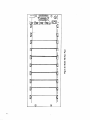
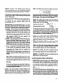
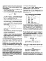
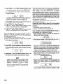
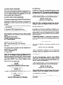
Example 4 Daisy Chain Configuration-In
a situation
where more than 100 channels are required the Model 706
can be connected to other Model 706 scanners to increase
the number of available channels. A total of five Model 706
scanners can be connected together to increase the number
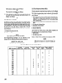
Table 2-9. Required
Description
Scanner Mainframes
Scanner Cards
Cables
2-10
Scan Example
Equipment
of available channels to 500. The method of connection is
shown in Figure 2-4 and is referred to as a daisy chain configuration.
One of the Model 706 scanners is programmed (by user
choice) as the master control instrument of the configuration.
The other Model 706 scanners are programmed as the slaves.
As slaves, the front panel controls of these instruments are
locked out (not functional) except for the power switch, front
panel Program 90 and 91, The power switch is functional but
when power is cycled the slave instrument powers up to the
slave condition. The only method out of the slave condition is
to activate Program 90 or 91. For complete details concerning
front panel programs refer to paragraph 2.9.
In this example the master Model 706 will be programmed to
scan 500 channels. The equipment required for this example
is shown in Table 2-9. For the sake of simplicity we will use
Model 7056 general purpose scanner cards for this example.
To help illustrate this daisy chain example we will choose the
following parameters:
1. First Channel is 1.
2. Last channel is 500.
3. Interval time is 0.2 seconds.
4. Number of poles is 2.
5. Use continuous scan mode.
for Daisy Chain Example
Specification
General Purpose
BNC to BNC
Mfg.
Keithley
Keithley
Keithley
Model
706
7056
7051-5
Qty
5
50
5
Use the steps outlined in Table 2-10 to program the daisy
chain configuration for the preceding parameters.
Upon the actuation of the START/STOP button in step 13,
the continuous scan sequence starts from the progammed
first channel. The continuous scan mode operates in the
same manner as described in example 3. The only difference
is that this example will scan 500 channels and then repeat
the sequence continuously.
Pressing the START/STOP
button during a continuous scan
sequence stops the scan at the presently displayed channel.
The channel remains closed and the START/STOP LED
turns off. To continue the scanning sequence from the
presently displayed channel press the START/STOP button.
The first and last channels are not battery backed up in the
daisy chain configuration.
To stop the scanning sequence and reset the Model 706 to
the programmed first channel (which is 1 in this example)
simply press the RESET button.
Table 2-10. Daisy Chain Example
SteD
5
Action
Install the Model 7056 scanner cards
into the Model 706 mainframes.
Set up the circuit shown in
Figure 2-4.
Select appropriate line voltage and
turn on the Model 706 scanners.
Program 4 Model 706 scanners as a
slave by pressing PRGM, 9, 2 on
each 706.
Select the remaining Model 706 as
the master of the configuration
by pressing PRGM, 9, 1.
Comments
Refer to paragraph 2.2.2.
Programs the Model 706 as slaves in the daisy
chain configuration.
Sets one Model 706 as the master control of the
daisy chain configuration.
NOTE
Initiating front panel PROGRAM 92 locks up the
Model 706 front panel, except for the power
button, PROGRAM 90 and 91. The following
message is displayed while front panel PROGRAM 92 is activated.
r
6
On the master control 706 press
PRGM, 6.
7
Press 2, ENTER.
8
9
10
Press 0, 0, 1, FIRST.
Press 5, 0, 0, LAST.
Press INTERVAL, 0, 0, 0, 2, 0, 0,
ENTER.
Press CHANNEL, RESET.
11
Press CONTINUOUS.
Press START/STOP.
.-_
-5LRl.E J
Selects PROGRAM 6. All programming will be done
on the master control 706 from this
step on.
Selects the 2-pole mode. Refer to paragraph
2.9 for more information concerning front panel
programs.
Programs channel 1 as the first channel.
Programs channel 500 as the last channel.
Programs the interval time for 0.2 seconds.
Turns on the CHANNEL LED, selects the
channel mode for display and resets to the
programmed first channel.
Selects the continuous scan mode and turns
on the CONTINUOUS LED.
Initiates the continuous scan mode sequence.
Figure 2-4. Daisy Chain Configuration
The display in the daisy chain configuration includes an additional digit to accomodate up to 500 channels, 1000 channels
in l-pole mode. The display is shown as follows:
I ml If
L
NOTE
Channels 1, 11 and 21 are the temperature
references for the cards.
01
Use the steps outlined in Table 2-11 to program the Model
706 for the preceding parameters.
I
NOTE
Scanning at a high rate of speed in the daisy
chain configuration may not show the scanned
channels on the mainframe’s display.
As you can see this temperature scan example is quite similar
to the continuous scan example (example 3). The only appreciable difference is the type of scanner card used in each
example. Except for specified values of the parameters
selected, front panel operation is similar in all scanning sequences.
_
Example 5 Temperature
Scan-With
the Model 7057A
thermocouple scanner card, the Model 706 can scan
temperature points. Since the Model 7057A combines the
functions
of a thermocouple
scanner and uniform
temperature reference it is especially useful for scanning
thermocouples. The input terminals are #lO alloy copper set
in an isothermal block to minimize temperature differences. A
thermistor sensor within the isothermal block is used with a
bridge network located on the Model 7057A. The
temperature of the heat sink is used to calculate the corrected
thermocouple output. The output voltages of each thermocouple must be converted to temperature (OCor OFI using appropriate thermocouple tables or polynominal equations.
These equations and tables are provided in the Model 7057A
Instruction Manual.
For more detailed information concerning temperature scans
refer to the Model 7057A Instruction Manual.
Example 6 Low Current Scan-With
the Model 7058 installed, the Model 706 is capable of scanning currents in the
range of picoamps. The Model 7058 is a low current scanner
card that is field installable in the scanner mainframe. The
Model 7058 is designed to introduce a minimum of offset current (c IpA), while guarding ensures that high isolation
(10153) is maintained between input signals.
The actual measurement of the low current should be done
with a high quality electrometer such as the Model 614 or
Model 619. A high quality picoammeter such as the Keithley
Model 480 could also be used. All three of these instruments
are capable of measuring in the range of picoamps with high
accuracy. To measure such low currents a number of
measurement parameters such as, input impedance, cabling,
measuie~ment~configuration, a&.,- must be taken into con;
sideration. This example does not attempt to give instructions
on low current measurement, the instruction manuals provided with each of the previously mentioned electrometers
In this example the Model 706 will be programmed to scan 25
separate temperatures. The following parameters will be programmed into the Model 706.
1. First channel is 1.
2. Last channel is 25.
3. Number of poles is 2.
4. Interval time is 3 seconds.
5. Use the continous scan mode.
Table 2-11. Temperature
Step
1
2
3
4
Action
Install a Model 7057A into
slots 1, 2 and 3 of the
Model 706.
Select appropriate line voltage
and turn on the Model 706.
Press PRGM, 6.
Press 2, ENTER.
Press 0, 0, 1, FIRST.
Press 0, 2, 5, LAST.
Press INTERVAL, 0, 0, 3, 0,
0, 0, 0, ENTER.
Press CHANNEL, RESET.
2-12
9
Press CONTINUOUS.
10
Press START/STOP.
Scan Example
Comments
Refer to paragraph 2.2.2.
Selects PROGRAM 6.
Selects the 2-pole mode, refer to paragraph
2.9 for more information concerning front
panel programs.
Programs channel 1 as the first channel.
Programs 25 as the last channel.
Programs the interval time for three seconds.
Turns on the CHANNEL LED, selects the
channel mode for display and resets the
instrument to the first channel.
Turns on the CONTINUOUS LED and selects
the continuous scan mode.
Initiates the continuous scan mode sequence.
and picoammeter give step by step instructions
measure low currents accurately.
on how to
In this example, the Model 706 will be programmed to scan
37 low current sources. Also, the following parameters will be
programmed into the Model 706.
1. First channel is 1.
2. Last channel is 37.
3. Interval time is 2 seconds.
4. Number of poles is 2.
5. Use single scan mode.
Use the steps outlined in Table 2-12 to program the Model
706 for the preceding parameters.
the type of scanner card used in each example. Except for the
specified values of the parameters selected, front panel
operation is similar in all scanning sequences.
For more detailed information concerning low current scans
refer to the Model 7058 Instruction Manual.
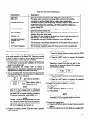
2.6 FRONT PANEL CLOCK OPERATION
The CLOCK group on the front panel contains the TIME and
DATE buttons. The clock continues to run after the Model
706 is turned off. This is because the clock’s power circuitry
is backed up by battery BTlOl. The time is shown in a 24
hour display-format. To display the time mode simply press
the TIME button. To set the time, use the steps outlined in
Table 2-13.
As you can see this low current scan example is similar to the
other scanning examples. The only appreciable difference is
Table 2-12. Low Current
Step
1
2
3
4
Action
Install a Model 7058 into slots
1, 2, 3 and 4 of the Model
706.
Select appropriate line voltage and
turn on the Model 706
Press PRGM, 6.
Press 2, ENTER.
8
Press 0, 0, 1, FIRST.
Press 0, 3, 7, LAST.
Press INTERVAL, 0, 0, 2, 0, 0,
0, ENTER.
Press CHANNEL, RESET.
9
Press SINGLE.
10
Press START/STOP.
5
6
7
Scan Example
Comments
Refer to paragraph 2.2.2.
Selects PROGRAM 6.
Selects the 2-pole mode, refer to paragraph 2.9 for more information concerning
front panel programs.
Programs channel 1 as the first channel.
Programs channel 37 as the last channel.
Programs the interval time for two seconds.
Turns on the CHANNEL LED, selects the
channel mode for display and resets the
instrument to the first channel.
Turns on the SINGLE LED and
selects the single scan mode.
Initiates the single scan mode sequence.
Table 2-13. Setting
SteD 1 Action
1
Press TIME”.
the Time
I Comments
Selects the time mode for
display and turns on the
TIME LED.
Set the time for 7:30 A.M.
I
Press the DATA buttons (O-9)
that correspond to the desired
time. For example, to set the
time for 7:30 A.M. press
0, 7, 3, 0, 0, 0, ENTER.
. .
*Pressing the TIME button during a scan sequence stops the sequence,
turns on the TIME LED and selects the time mode for display.
2
2-13
Upon the actuation of the ENTER button, the time is set to
7:30 A.M. As another example, set the time to 7:30 P.M. by
pressing 1, 9, 3, 0, 0, 0, ENTER.
NOTE
If upon power up the Model 706 displays the
slave or no loop message (refer to paragraphs
2.9.11 and 2.9.12) activate Program 90 return
the Model 706 to normal operating conditions.
To activate Program 90, press PRGM 9,0.
To display the DATE mode, simply press the DATE button.
The date is displayed in one of two formats. The formats are
the American date format and the International date format.
These formats are described in paragraph 2.9.2. The formats
are selected exclusively by front panel Program 1. Refer to
paragraph 2-9 for complete details concerning the front panel
programs. To set the date, use the steps outlined in Table
2-14.
As another example, set the date to August 18th for the international date format by pressing:
1. PRGM, 1 (Selects front panel Program 1 for display.)
2. 1, ENTER. (Selects the international date format.)
3. 1,8,0, 8, ENTER. (Enters 18.08 for the date August 18th.)
2.7 DETAILED
TION
FRONT PANEL CONTROLS
Cl1
F
2. CHANNEL-The
CHANNEL button selects the channel
mode for display. The channel number is displayed on the
front panel as a two digit number, except in the daisy chain
or matrix mode. Upon power up the Model 706 reverts to
the channel mode.
Pressing the CHANNEL button while the Model 706 is in
the channel mode increments the channel number by one.
Actuation of the clock, date, PRGM, single, continuous,
or interval functions takes the Model 706 out of the channel mode. Actuation of the reset function during any of the
front panel programs except Programs 90, 91, 92 and 99
reverts the Model 706 to the channel mode.
DESCRIP-
1. POWER ON/OFF-The
On/Off switch operates on the
push-push principle. Depressing this button turns the instrument on. Once the instrument is on, pressing (releasing) this button turns the instrument off. When the Model
706 is turned on it goes through a power up sequence as
outlined in paragraph 2.3. When the power up sequence is
complete the Model 706 displays the following:
[
To identify the previous state of the functions that are not
affected by power up, simply activate the desired function.
When the function is activated the previous state for that
function is displayed. Refer to paragraph 2.5.1 for information concerning the actuation of the desired function.
Refer to Table 2-2 for power up default conditions.
3. OPERATION-The
OPERATION group consists of four
function buttons: FIRST, LAST, CLOSE and OPEN. The
buttons are described as follows:
lx-
where:
01 = Channel Number One
F = First Channel*
o = Channel Open
*If channel 1 was previously programmed as the first
channel, last channel or both, it is displayed as such. This
is because the first and last functions are battery backed up
and not affected by power up.
CLOSE-Upon
actuation of the close function the
present!y disp!ayed channe! rt!asesi !f fhF( prasent!y
displayed channel is already closed, pressing the CLOSE
button has no effect on the channel. When the presently
displayed channel is open and the CLOSE button is pressed the open and close digit (furthest digit on the right of
the display) changes to a c and that channel is closed.
Refer to the following display.
iYnT--&
Open and Close Digit
o = Channel Open
c = Channel Closed
Table 2-14. Setting
SteD 1 Action
Press DATE.*
1
the Date
I Comments
Selects the date mode for display and turns on
the DATE LED.
Press the DATA buttons (O-9)
2
For example, to set the date to August 18th
that correspond to the desired
for the American date format follow steps 3,
date.
4 and 5.
Press PRGM, 1.
3
Selects front panel PROGRAM 1 for display.
Press 0, ENTER.
4
Selects the American date format.
Press 0: 8, 1, 8, ENTER.
5
Enter 08.18 for the date August 18th.
_ -_--.
..“Pressing the DATE button during a scan sequence stops the sequence, turns on the DATE LED
and selects the date mode for display.
2-14
To ensure reliable performance, do not simultaneously close
more relays than the mainframe power supply can handle. The
closure limit depends on factors such as the drive current of
each relay, temperature, and ventilation.
Pressing the-FIRST button designates the channel
channel and the display format is as follows:
where:
01 = Present Channel
F = First Channel
o =’ Channel Open
Table 2-I 5 lists the maximum current available from the mainframe power supply for energizing relays under different operating conditions. To find the maximum number of simultaneous
relay closures, divide the current listed by the specified drive
current per relay. Remember that some cards energize two relays for each channel (e.g., Models 7063 and 7067).
Table 2-15.
Temp.
23’ C
50” c
Maximum Relay Drive Current
Mainframe
Bench-top
(Louvers
unobstructed)
4.3A
3.3A
There are a number of ways to change the designated
channel they are listed as follows:
from
Rackmount
(1” space
between
scanners)
Rackmount
(No space
between
scanners)
4.3A
2.3A
4.3A
1.3A
NOTE
Powering the unit down will not change the designated first channel.
LAST - Upon actuation of the LAST button the presently displayed channel is designated as the last channel of the multichannel configuration. if the presently displayed channel has already been specified as the last channel, pressing the LAST
button has no effect on the channel or the display. If the presently displayed channel has not been designated as the last
channel, the display is as follows:
cl
--I
where:
01 ,= Present Channel
o = Channel Open
Open and Close Digit
Channel
Channel
first
A. Select the desired new channel then press FIRST.
B. Activate Program 99.
C. Activate Program 90.
OPEN - Upon actuation of the open function the presently displayed channel opens. If the presently displayed channel is already open, pressing the OPEN button has no effect on the
channel. When the presently displayed channel is closed and
the OPEN button is pressed the open and close digit (furthest
digit on the right of the display) changes to an o and that channel
is opened. Refer to the following display.
o=
c=
as first
Open
Closed
Pressing the LAST button designates the channel as last channel and the display format is as follows:
NOTE
Close and open for each channel remains valid
even when not viewing the channel or the display.
I
/
10
L, 01
where:
10 = Present Channel
L = Last Channel
o = Channel Open
FIRST - Upon actuation of the FIRST button the presently displayed channel is designated as the first channel of a multichannel configuration. If the presently displayed channel has already been specified as the first channel, pressing the FIRST
button has no effect on the channel or the display. If the presently displayed channel has not been designated as the first
channel, the display format is as follows:
There are two ways of changing
they are listed as follows:
the designated
last channel
where:
01 = Present Channel
o = Channel Open
+
2-15
A. Select desired new channel and press LAST.
B. Activate Program 99.
O-g-The O-3 data keys allow entry of numerical data onto
the display. The O-9 keys can be used to enter numerical
constants on the display for certain functions such as interval time, channel number, front panel programs, time and
date.
NOTE
Powering the unit down will not change the
designated last channel.
If the presently displayed channel is designated as the first
and last channel the display format is as follows:
I IU FLol
I
I
where:
- -30 = Present Channel
F = First Channel
L = Last Channel
o = Channel Open
4. CONTROL-The
CONTROL group of buttons consist of
the RESET button and the INTERVAL button. The buttons
and their functions are described as follows:
RESET-Actuation
of the RESET button opens all channels of the Model 706 and reverts the display to the
designated first channel. Actuating the RESET button during a single or continuous scan mode sequence stops the
scan sequence, opens all channels and reverts the display
to the designated first channel. The RESET button is inactive in the time, date, interval and Programs 8, 90, 91, 92
and 99.
INTERVAL-The
INTERVAL button selects the programmed interval time for display. The interval time is the programmed time each channel is closed when using the step,
single or continuous scan mode. The interval time ranges
from 000.010 seconds to 999.999 seconds. Upon the actuation of front panel Program 99 the interval time is
reverted to the default condition of 000.010. Powering the
unit down will not change the programmed interval time.
.
There are two ways the interval time can be changed and
they are as follows:
A. Activate Program 99 (resets to 000.010).
B. Press the INTERVAL button and then press the appropriate number from 000.010 to 999.999. Press
ENTER.
5. DATA-The
DATA group of buttons consist of the O-9,
CANCEL and ENTER buttons. They are described as
follows:
ENTER-Upon
actuation, the ENTER button loads the
displayed data for channel number, interval time, time,
date and program modes into the Model 706. In the program mode, the ENTER button initiates the selected program (O-7) after the necessary data is entered onto the
display.
CANCEL-During
the entry of data (C segment cursor is
flashing) the CANCEL button cancels the present display
and- reverts the instrument to the previous display. The
CANCEL button is functional only when entering data onto the display in the channel, interval, time, date and program modes.
Refer to Table 2-16 for an example of the CANCEL button
function.
In Table 2-16 the interval display mode is selcted and a 120
second interval time is entered onto the display. For some
reason or other the interval time in step 2 is an error so the
CANCEL button was pressed to revert the display to the
previously programmed interval time.
6. SCAN-The
SCAN group of buttons consists of SINGLE,
CONTINUOUS, and START/STOP buttons. These three
buttons select the different scan modes and are described
as follows:
CONTINUOUS-Actuation
of the CONTINUOUS button
selects the continuous scan mode and turns on the continuous LED. The continuous scan mode allows the user to
scan through the programmed channels at the programmed interval rate, continuously. The continuous scan mode
is initiated upon the actuation of the START/STOP button
or upon receiving the appropriate external trigger pulse.
Pressing the START/STOP button during a continuous
scan sequence stops the scan at the presently displayed
channel. To continue the scan sequence simply press the
START/STOP button.
Table 2-16. CANCEL Function
step
1
2
3
2-16
Action
Press INTERVAL.
Press 1, 2, 0, 0, 0, 0.
Press CANCEL.
Example
Comments
Selects interval display mode and turns on
the INTERVAL LED.
Enters 120 second interval time on the display.
Reverts the interval time data of step 2 to
the previously programmed interval time.
SINGLE-Actuation
of the SINGLE button selects the
single scan mode and turns on the single LED. The single
scan mode allows the user to scan through the programmed channels at the programmed interval rate, one time.
TIME-The
TIME button selects for display the 24 hour
time clock. The format showing 2:45 pm is as follows:
The single scan mode is initiated upon the actuation of the
START/STOP button or upon receiving the appropriate
external trigger pulse.
The time can be set by pressing the TIME button, entering
the appropriate time onto the display and then pressing the
ENTER button. Note that the time 28:00:00 to 33:59:59
can be entered. It is invalid but it can be entered.
Pressing the START/STOP button during a single scan sequence stops the scan at the presently displayed channel.
To continue the scan sequence simply press the
START/STOP button.
DATE-The
DATE button selects the date mode for
disolav. The date disolav has two formats. The formats
showing June 17th are a’s follows:
-START/STOP-The
START/STOP button is an alternate action control that has three functions. The three
functions are the start function, stop function and the step
scan mode. These functions are described as follows:
A. START-The
start function of the START/STOP button initiates the selected scan mode. When all the
parameters (interval time, first and last channels, scan
mode, etc.1 of a multi-channel configuration have been
programmed and the user is ready to scan the channels, press the START/STOP button to initiate the
scan sequence. During the scan sequence the
START/STOP LED is activated.
B. STOP-The stop function of the START/STOP button
stops the previously initiated scan sequence. That is,
pressing the START/STOP button during a scan sequence stops the sequence at the presently displayed
channel and turns off the START/STOP
LED. The
STOP function is active only during a scan sequence.
C. STEP-The step scan mode allows the user to manually step through the programmed channels. The step
scan mode is selected by pressing the channel button,
programming the interval rate and pressing the
START/STOP button. When the interval rate has been
programmed and the user is ready to manually scan the
press the START/STOP button to scan one
- channels,
~~
channel.
Upon initiating the step scan mode the START/STOP
LED turns on, the presently displayed channel is closed
for the programmed interval rate, the channel is then
opened and the START/STOP LED turns off. At this
point the Model 706 advances to the next channel and
then stops.
To scan the next channel press the START/STOP button and the Model 706 repeats the same sequence with
the presently displayed channel.
7 .CLOCK-The
CLOCK group of buttons consist of the
TIME and DATE buttons. The clock (time and date) continues to run after the instrument is powered down
because the clock circuitry is backed up by battery BTlOl .
The two buttons are described as follows:
~W5.UUl
American Date Format /I
International Date Format 1
’
/ 7 D b
I-
The formats are selected by front panel Program 1. Refer
to paragraph 2-9 for more information concerning front
panel programs. The date can be set by pressing the DATE
button, entering the appropriate date onto the display and
then pressing ENTER. Refer to paragraph 2.6.
8. PRGM-The
PRGM button when pressed shows a
display that prompts the user to select one of the 15 front
panel programs. Refer to paragraph 2.9 for complete
details and examples of the front panel programs.
9. IEEE Indicators-The
IEEE bus indicators (TALK,
LISTEN and REMOTE) identify the present status of the
IEEE-488 bus. The indicators are described as follows:
TALK-The
TALK LED when lit indicates that the Model
706 is in the talk mode. The Model 706 does not have to
be in the remote mode for it to be in the talk mode.
LISTEN-The
LISTEN LED when lit indicates that the
Model 706 is in the listen mode. The Model 706 must also
.be in the remote mode for it to be in the listen mode.
REMOTE-The
REMOTE LED when lit indicates that the
Model 706 is in the remote mode.
2.6 DETAILED
REAR PANEL DESCRIPTION
1. CARD SLOTS-Each
card slot on the Model 706 rear
panel can accomodate one scanner card. There are a total
of 10 card slots. That is, the Model 706 can accomodate 10
scanner cards. The Model 706 with 10 scanner cards has
up to 100 2-pole channels. Refer to paragraph 2.2.2 for instructions on how to remove or install the various scanner
cards.
2. EXT. TRIGGER-The
external trigger is a BNC connector
that initiates the selected scan mode (single, step or continuous) in the same manner as the START/STOP button.
The input trigger pulse must be a negative going lTL level
pulse with a minimum duration of met. The selected scan
mode is initiated upon the negative transition of the pulse.
2-17
This feature can be used to trigger the Model 706 into the
selected mode using another instrument.
3. CHANNEL READY-The
CHANNEL READY output is a
BNC output connector that provides a negative going lTL
level pulse with a duration of greater than 10pec at the
completion of the programmed settling time. This features
can be used to inform another instrument (DMM, Source,
etc.) that the present channel settling time is completed.
4. ALARM/SERIAL
IN-The ALARM/SERIAL IN connector has two functions. The alarm out function and the
serial in function. They are described as fokows:
ALARM-The
alarm function outputs a negative going
TTL level pulse with a duration of greater than 10wec. This
‘pulse appears once upon reaching the programmed alarm
time. The alarm time can be programmed by front panel
Program 7. When the alarm time is set to 00.00.00 the
pulse does not appear. The programmed alarm time is set
to 00.00.00 when power to the instrument has been
cycled. Refer to Table 2-3.
SERIAL IN-The serial in function is used in a daisy chain
configuration where the ALARM/SERIAL IN connector is
connected to the SERIAL OUT connector of another
Model 706. Refer to example 4 of paragraph 2.5.4.
5. SER. OUT-The
SER. OUT connector is a BNC output
connector that provides a connection to another Model
706 for a daisy chain configuration. The SERIAL OUT connector is applied to the ALARM/SERIAL IN connector of
another Model 706. Refer to example 4 of paragraph 2.5.4.
6. DIGITAL l/O-The
DIGITAL I/O port consists of 16
digital input and output lines along with four lines that are
+ 5V and IEEE common. Eight of the I/O lines can be used
for inputs and eight can be used for outputs. The outputs
will drive one TTL load and the inputs are TTL compatible.
For more information concerning the digital I/O port refer
to paragraph 3.5.8 step 15.
7. IEEE-488 INTERFACE-The
IEEE bus connector provides bus connection to the Model 706. The connector
mates with the Keithley Model 7008-3 and 7008-6 cables.
For more detailed information concerning the IEEE connector refer to paragraph 3.3.
8. LINE FUSE-This
is the line power fuse and it is rated
as specified in Table 5-2.
9. LINE RECEPTACLE-The
line power receptacle mates
with a three wire line cord which provides connections to
line voltage. For correct line voltage selection refer to
paragraph 5.3.
2.9 FRONT PANEL PROGRAMS
This section contains instructions necessary for operating the
2-18
15 internal proSCams of the Model 706. The programs are activated by pressing the PRGM button along with the button
representing the appropriate program number. The programs
do a number of various tasks which are summarized in Table
2-17.
Program Notes
1. Each program is entered by pressing the PRGM button
followed by the desired program number.
2. Pressing the PRGM button selects the program mode and
the following is displayed:
r--TzTj
--
As you have noticed, the question mark is flashing. This is
prompting the operator to enter the desired program
number (refer to Table 2-17). After entering the program
number the Model 706 goes into the program selected.
Then the display prompts the operator to enter numerical
data. Numerical data varies with each program.
3. New programs may be entered without clearing a program
that is presently running. To do so, press the PRGM button followed by the desired program number.
4. Data is entered into the digit whose “C” segment (cursor)
is flashing by pressing the desired number button. The
“C” segment of a display is shown as follows:
1-G
5.
6.
7.
8.
9.
+fment
As each digit is entered, the cursor moves one place to the
right until the last digit on the right is reached. Then it is
cycled to the first digit on the left.
Only as many significant digits as necessary need to be
entered. The Model 706 will complete the constants with
trailing zeroes where necessary.
Invalid keys will be ignored. If an invalid key is pressed the
blinking “C” segment (cursor) remains at the current digit.
If an incorrect digit is entered, the complete constant must
be reentered. The new value may be entered by cycling
the display around to the beginning. To do this, repeatedly
press one of the number buttons.
If too many digits are entered, the display begins again at
the first digit on the left. All the digits in the constant must
then be entered again. This applies only to Programs 0,2,
3, 6 and 7.
Once all the digits of the desired constants are shown on
the display, the constant is entered into the program by
pressing the ENTER button. This applies only to Programs
0 through 7.
Table 2-17. Summary
of Front Panel Programs
Program
0”
1
2
3
4
Operation
Digital I/O (Input/Output) Port
American/International
Date Format
Relay Settle Time
Set IEEE Primary Address
Save Relay Set Up
Recall Relay Set Up
:
Pole Configuration (0, 1, 2 or 41
7*
Alarm Time Set
8”
Diagnostic Self Test
Stand Alone
90
Master
91
Slave
E*
Inspect Mode
Clear
Reset
ii;*
*Denotes NOT battery backed up.
2.9.1 Program 0 Digital I/O
Program 0 allows the user to control the outputs on the
digital I/O port. The I/O port is located on the rear panel of
the Model 706. The output code is displayed in base eight
(octal) on the front panel. The actual I/O port output data is
in 8 bit form. The range of octal output data that can be
entered on the front panel display is 0 to 377. The maximum
octal data is 377 which corresponds to 11111111 in BCD. If
the front panel data is entered as 377 then the digital I/O output data is 11111111. To initiate Program 0 use the following
procedure:
1. Press PRGM and the following is displayed:
T
I
I
I
l-5-o
2. Press 0 and the kIlowing
seconds:
r’
:
2.9.2 Program
1 Date Format
Program i is used to select one of two date formats. The two
formats are the american date format and the international
date format. The display format is as follows:
American: mm.dd
International: dd.mm
where: mm = month
dd = day
To enable Program 1 and select the international date format,
use the following procedure:
1. Press PRGM. Selects program mode and displays Pro 1.
NOTE
The flashing question mark on the display prompts the user for the decimal program number.
2. Press 1. This action selects Program 1 and displays the
following:
I
H fl
E
/
jgf!
Indicates which Format
where:
AOEI = American or International
0 = American Date Format
1 = International Date Format
Notice that the last digit’s “C” segment is flashing. This
prompts the user to enter the appropriate data.
3. Press 1. This action selects the international date format.
4. Press ENTER. This action displays the data in the international date format and turns on the DATE LED.
L
is displayed for approximately 0.5
After the Out/In message is displayed, the Model 706
displays the following:
1 ucJauuu/
Where the first three digits represent the digital output (in
octal) and the last three digits represent the digital inputs
(in octal).
NOTE
The digital l/O inputs are defined by the connections on the input pins. With no connections on
the input pins (located on the rear panel) the inputs are undefined. The digital I/O outputs are
programmed by using Program 0.
3. Press 0,7,7, ENTER. This action programs the output bits
on the digital I/O port for 00111111.
To enable program 1 and select the american date format use
the following procedure:
1. Press PRGM. Selects program mode, displays Pro ? and
turns off the DATE LED.
2. Press 1. Select Program 1 and the following is displayed:
n
3. Press 0. This selects the american date format and turns on
the DATE LED.
4. Press ENTER. This displays the date in the american date
format and turns on the DATE LED.
NOTE
The date format is battery backed up. Shutting
off the power to the unit does not affect the date
format. It will remain as programmed until it is
reprogrammed.
The date, as well as the time, continues to run even when
power to the instrument is shut off. The reason for this is that
the clock’s power circuitry is backed up by battery BTlOl.
2-19
Setting or changing the date is as simple as selecting the date
format. For example, use the following procedure to set the
date in american date format for November 24.
1. Press PRGM. Selects program mode and displays Pro ?.
2. Press 1. Selects Program 1, turns off the DATE LED and
displays the following:
RUE I 171
I
3. Press ENTER. The american date format was selected in
the previous procedure. Pressing ENTER displays the date
in the american date format and turns on the DATE LED.
4. Press 1, 1,2,4, ENTER. This action programs the date for
- November 24 and displays the following:
I PY
2.9.3 Program
2 Relay Settle Time
Program 2 is used to program the amount of time
(000.005sec to 999.999sec) the relays and all the measurement equipment connected to a particular channel has to settle out. Do not confuse the settle time with the interval time.
The interval time is the selected time a relay is closed in a
scanning sequence. The interval time overrides the settle
time. That is, if the settle time is set to two seconds and the
interval time is set to one second the scan sequence will
operate at one second interval rate.
Therefore, the settle time must always be shorter in duration
than the interval time.
At the end of the programmed settle time the Model 706 outputs a negative going, lTL level pulse with a duration of
greater than 1Opec. This pulse appears at the CHANNEL
READY output. The CHANNEL READY output is BNC connector located at the rear panel of the Model 706. The purpose of the settle time program is to have a selectable settle
.time for all instruments connected to a particular channel.
Then the pulse that appears at the CHANNEL READY output
can be used to inform another instrument (e.g. DMM, printer
or even the Model 706) that the settle time is complete.
To initiate Program 2 use the following procedure:
1. Press PRGM. This selects the program mode and displays
Pro 1.
2. Press 2. Selects Program 2 and displays the following for
approximately 0.5 seconds.
,
SEttlEl
After the settle message is displayed,
displays:
2-20
the Model 706
This displayis shown is seconds. The minimum settle time
is 000.005 seconds and the maximum settle time is
999.999 seconds. The settle time is not affected by power
up. This is because the circuitry is backed up by battery
BTlOl.
Programming the settle time is a simple procedure. For example, use the following procedure to program the settle time to
001 .OlO seconds.
1. Press PRGM. Selects the program mode and displays
Pro 1.
2. Press 2. Selects Program 2 and displays the settle message
described in step 2 of the previous procedure. Then the
previously programmed settle time is displayed.
3. Press 0, 0, 1, 0, 1, 0, ENTER. This step loads 1.01 seconds
as the settle time on the display. Pressing ENTER programs 1.01 seconds as the settle time and the Model 706
reverts to the channel mode at the previously displayed
channel.
NOTE
Initiating a new interval time resets the settle
time counter. If the settle time is greater than the
interval time the CHANNEL READY output
pulse does not appear upon the completion of a
scanning sequence.
2.9.4 Program 3 Set IEEE Primary
Address
Program 3 is used to set the primary address of the Model
706 for IEEE-488 bus operation. The primary address of the
Model 706 is factory set to 18, but it may be set to any value
between 0 and 31 via front panel Program 3. This is a convenient feature that eliminates the cumbersome rear panel switches that are generally used in other instruments to set
primary address.
The primary address specified in the controller’s programming language must agree with the primary address of the
Model 706. Front panel Program 3 is the only way to change
the Model 706’s primary address.
NOTE
If other instrumentation is connected to the bus,
be sure that each device has a different primary
address. If the precaution is not observed, erratic operations may result.
To initiate Program 3 and change the primary address to 22
use the following procedure:
1. Press PRGM. Selects the program mode and displays
Pro 1.
2. Press 3. Selects Program 3 and displays the following:
where:
IE = IEEE Indicator
18 = Primary Address
3. Press 2,2, ENTER. This step loads the number 22 onto the
display. Pressing the ENTER button programs the primary
address to 22 and reverts the Model 706 to the channel
mode at the previously displayed channel.
4. Press PRGM, 3. This step shows the user that the primary
address has indeed changed to 22.
5. Now that you know how, change the primary address
back to 18.
2.9.5 Program 4 Save Relay Set Up
Program 4 is used to save (store) the present relay set up for
future use. This program is capable of storing 75 separate
relay set ups. This means the user can program 75 different
relay set ups, store the set ups, then use the stored set ups
when the need arises without reprogramming.
Program 4 is very useful in a situation where the instrument
and/or experiment is going to be shut down for a period of
time and the user does not want to reprogram the relay set up
when power is returned to the unit. The program is also
helpful when the user has programmed one relay set up and
needs to go to another completely different set up without
destroying or losing the existing set up. In this case it’s possible to program one relay set up and store it with Program 4,
then program a different set up and store it with Program 4.
This way the user has both relay set ups stored for further
use.
NOTE
The Model 706 can only use one relay set up at a
time, they cannot be used simultaneously.
As an example of using Program 4, program the Model 706
for 10 channels with the odd numbered channels closed and
the even numbered channels open. When the set up is complete, save the set up by using Program 4. Use the following
procedures to implement this example:
1. Press RESET. Selects the channel mode and reverts the
instrument to the programmed first channel.
2. Press 0, 0, 1, FIRST. Selects channel 1 as the first channel.
3. Press 0, 1, 0, LAST, Selects channel 10 as the last channel.
4. Press RESET. Reverts to the programmed first channel.
5. Press CLOSE. Closes presently displayed channel.
6. Press CHANNEL, CHANNEL, CLOSE. Advances the
Model 706 to channel 3 and closes it.
7. Press CHANNEL, CHANNEL, CLOSE. Advances the
Model 706 to channel 5 and closes it.
8. Press CHANNEL, CHANNEL, CLOSE. Advances the
Model 706 to channel 7 and closes it.
9. Press CHANNEL, CHANNEL, CLOSE. Advances the
Model 706 to channel 9 and closes it.
10. Press PRGM, 4. Selects program mode, selects Program
4 and displays the following:
11. Press 1, ENTER. Select the relay set up 1 to be stored and
when ENTER is pressed the set up is stored in location
SAVOl . The display is then reverted to the channel mode
at the previously displayed channel.
To verify that the relay set up has been stored use the following procedure:
1. Press RESET. Reset to the programmed first channel and
opens all relays.
2. Press PRGM, 5. Selects program mode and also Program
5.
3. Press 0, 1, ENTER. Selects location 01 and recalls the set
up.
4. Press CHANNEL nine times and notice that the odd
numbered channels are all closed and the even numbered
channels are all open. This verifies that relay set up was
indeed stored using Program 4.
For another test of the relay set up, shut off power to the
Model 706 for a few minutes. Turn the instrument back on
and press PRGM, 5,0, 1, ENTER. Notice that the odd channels are closed and the even channels are open. Thus, even
when power to the instrument was shut off the relay set up
remained in memory.
To store an additional relay set up, program the set up and
press PRGM, 4, 0, 2, ENTER. This action saves the relay set
up without disturbing the previously stored set up. This can
be done with up to 75 separate set ups.
The factory set values of Program 4 are all channels open and
channel 1 is the programmed first and last channel.
NOTE
Program 4 saves the entire relay set up programmed on the Model 706. It does not save just the
relay set up between the programmed first and
last channels. Program 4 also works in the
matrix mode.
2.9.6 Program 5 Recall Relay Set Up
Program 5 is used to recall a previously stored relay set up.
Program 4 and 5 work in conjunction with each other. Program 4 is used to store a relay set up while Program 5 is used
to recall the relay set up that was stored using Program 4.
Program 5 also recalls the programmed first and last channels
along with the relay set up that was stored in the example of
Program 4.
In the example of Program 4, 10 channels were selected with
the odd channels closed and the even channels open. The set
2-21
up was stored and then the Model 706 was reset by using the
RESET button. This is the point where we will start the example of Program 5. To recall the stored relay set up, use the
following procedure:
1. Press RESET. Reverts instrument to programmed first
channel and opens all channels.
2. Press PRGM, 5. Selects program mode and also Program
5. After the 5 button is pressed the Model 706 displays the
following:
This display indicates that the recall program has been
activated. The display prompts the user for the specific
_relay set up that is stored (1 through 751.
3. .Press 0, 1, ENTER. Selects relay set up number 1 to be
recalled and when ENTER is pressed the set up is recalled.
After ENTER is pressed, the Model 706 recalls relay set up
number 1 and displays the channel that was shown
previous to pressing PRGM. In this case, the following is
displayed because step 1 reset the display to the programmed first channel.
..-.:
In order to verify that the stored set up was recalled proceed to step 4.
4. Press CHANNEL nine times and notice that the odd
numbered channels are closed and the even numbered
channels are open. This shows that the stored relay set up
was indeed recalled by Program 5.
The factory set values of Program 5 are all channels open
and the programmed first and last channels are set to 1.
Program 5 also works in the matrix mode, refer to
paragraph 2.9.13 for an example.
In the matrix mode of operation pressing the START/STOP
button displays the Recall display along with the present
memory location. Pressing the START/STOP button in the
matrix mode and while the recall display is shown, advances
the instrument to the next memory location. Pressing the
CHANNEL button while the recall display is shown, selects
the channel display mode. By repeatedly pressing the CHANNEL button the crosspoints of that memory location are
displayed. If in the inspect mode, all the closed crosspoints
can be displayed (one at a time, not simultaneously). Refer to
paragraph 2.9.13 for inspect mode information.
Pressing the START/STOP button repeatedly to advance
through the stored memory locations is an easy way to locate
a desired memory location. This procedure will go through all
the stored locations up to location 75 or to where a memory
location has been cleared (Program 94Ior to the last stored
memory location and then loop back to memory location 01.
If memory location 01 was cleared using Program 94, attempting to recall the location is not valid and cannot be recalled.
This is true for all the locations.
2-22
6 Pole Configuration
Program 6 is used to program the desired number of
measurement poles or to select the matrix mode.
Measurement
Poles-The
Model 706 permits either 1,2 or
4-pole measurements. Table 2-18 contains a list of the different scanner cards and which pole configuration to use
with each scanner card.
Table 2-16. Scanner
/I
1
2.9.7 Progra!
._
Scanner
Card
7052
7053
7054
7056
7057A
7058
7059
Card Pole Configuration
Pole Configuration
to Use
0 pole (Matrix)
2 and 4 pole
2 pole
1,2or4pole
2 pole
2 pole
2 pole or 4 pole
.
The l-pole configuration can be used by operators who need
to switch just one (HI) side of their configuration. The 2-pole
configuration can be used for normal measurements. The
Cpole configuration can be used for 4-terminal ohms or a
switched HI, LO COM and Guard measurement. The matrix
mode (O-pole on the Model 706) can be used to switch any
one point to another.
The pole configuration is displayed by activating Program 6.
The pole configuration can be changed by activating Program 6 and pressing the desired number (0, 1,2 or 4). For example, use the following procedure to change the present
pole configuration to 4.
1. Press PRGM, 6. Selects Program 6 and displays the
fallowing:
/ PUlE
21
NOTE
Upon the actuation of front panel Program 99,
the Model 706 sets the pole configuration to 2.
Power up does not affect the pole configuration.
2. Press 4, ENTER. Loads 4 onto the display and when
ENTER is pressed, the pole configuration is set to 4. The
Model 706 then reverts to the channel mode, turns on the
channel LED and dislays the programmed first channel.
NOTE
Before pressing the ENTER button in step 2, the
Model 706 ignores the entry of any invalid
number (3, 5, 6, 7, 8, 9) for this program.
To verify that the pole configuration was changed to 4, press
Program 6, and the display shows that it was changed to 4.
Now change the pole configuration to 2. This can be done by
activating front panel Program 99 or by using the following
procedure:
1. Press PRGM, 6.
2. Press 2, ENTER.
1
2
r-nlnrq
-ROWS
I.
In the l-pole mode the display is slightly different as shown in
the following display.
3
4
~~-
The additional display digit is due to the fact that up to 200
channels may be realized in the l-pole mode. This only works
with the Model 7056 general purpose scanner card.
Matrix
Mode-Using
the Model 7052 matrix scanner card
with the Model 706 requires that the matrix mode be activated.The matrix mode precludes the use of the continuous
or single scan modes. The matrix mode can only be used in
the step scan mode. To activate the matrix mode use the
following procedure:
1. Press PRGM, 6. Selects program mode and Program 6.
2. Press 0, ENTER. Selects matrix mode.
After the ENTER button in step 2 is pressed, the Model
706 is placed in the matrix mode and the following is
displayed:
I uu I Id
I
where the format is as follows:
COLUMNS
-lj
&-&
&
k
,5&,
t MI6
L---J
Figure
A TYPICAL CROSSPOINT ON THE
MODEL 7052 MATRIX CARD
CONSISTS OF A 3-POLE
FORM A RELAY AS SHOWN.
2-5. Model
7052 Matrix
Scheme
3 Denotes row #3.
c Denotes the crosspoint is closed.
Therefore,the display 004 3 c means that the crosspoint of
unit #l, card #l, column #4, row #3 is closed.
Example 2-For another example, consider a 4 x 50 matrix
which would be 10 Model 7052 matrix cards with jumpers installed between the rows of each card.- A matrix display could
be as follows:
I CJW Ycl
nnn m 0 or C
where:
nnn = Three digit number displaying the column. Where
there can be a total of five columns per card, 10 cards per
706, five daisy chained 706’s maximum. This can be a
maximum of 250 columns.
m = The row from 1 to 4.
o or c = The crosspoint is either opened or closed.
The matrix mode displays crosspoints instead of channels.
Crosspoints consists of the junction of one row with one column. On each Model 7052 matrix card there are five columns
and four rows. Refer to Figure 2-5.
Example
l-For
an example of a matrix crosspoint display
consider the following:
where:
048 Denotes unit #l (001 through 050 denotes
048 Also, denotes card #lO of unit #l (046
denotes card #lO of unit #l).
048 Also, denotes column #3 of card #lo of
through 050 denotes columns of card #lo
4 Denotes row #4.
c Denotes the crosspoint is closed.
unit #l).
through 050
unit #l (046
of unit #l).
Therefore, the display 048 4c in a matrix means that the
crosspoint of unit #l, card #lo, column #3, row #4 is closed.
Example ~--AS another example, consider a 40 x 5 matrix
which would be 10 Model 7052 matrix cards with jumpers installed between the columns of each card. A matrix display
could be as follows:
I UY3 rlo!
UUY 34
where:
004 Denotes the #l (001 through 050 denotes
004 Also, denotes card #l of unit #l (001
denotes card #l of unit #l).
004 Also, denotes column #4 of card #l of
through 005 denotes the columns of card
’
123451
unit #lI.
through 005
unit #l (001
#l of unit HI.
where:
043 Denotes unit #l (001 through 050 denotes unit #ll.
043 Also, denotes card #9 of unit #l (041 through 045
denotes card #9 of unit #l).
043 Also, denotes column #3 of card #9 of unit #l (041
through 045 denotes columns of card #9 of unit #l).
2 Denotes row #2.
o Denotes crosspoint is open. \
2-23
Therefore, the display 043 20 means that in a 40 x 5 matrix
set up the crosspoint of unit #l, card #9, column #3, row #2 is
open.
Refer to Figure 2-6, Table 2-19 and Table 2-20 for further
clarification of the matrix mode display.
l-Pole
Nomenclature
Channel 1 = Channel
Channel 2 = Channel
Channel 3 = Channel
Channel 4 = Channel
I, ,r ,I
,t
2-Pole
Nomenclature
1 Relay + Output
1 Relay + Output
2 Relay + Output
2 Relay + Outbut
,I ,I
tt
I,
J
Relay
Relay
Relay
Relay
tt
K112
Kill
K112
Kill
I,
,
.i
Channel 19 = Channel 10 Relay + Output Relay K112
Channel 20 = Channel 10 Relay + Output Relay Kill
2.9.6 Program 7 Set Alarm Time
IS CLOSED
DENOTES COLUMNS
DENOTES CARD
DENOTES SLAVE
Figure 2-6. Matrix
Table 2-19. Matrix
Display
Unit Number
Unit Number
Master
Slave #l
Slave #2
Slave #3
Slave #4
Clarification
Display Assignment
Display Assignment
001 through 050
051 through 100
101 through 150
151 through 200
201 through 250
Program 7 is used to set the alarm time. The alarm time is the
preprogrammed time that the Model 706 outputs a negative
going lTL level pulse with a duration of greater than lO@ec
at the ALARM/SERIAL IN connector. The ALARM/SERIAL
IN cQnnector is located on the rear panel of the Model 706.
The alarm pulse can be used to inform another instrument to
start a measurement sequence. The external instrument (e.g.
controller, DMM, printer, etc.) can then start on its own
function in the measurement system. The alarm time is
displayed as a 24 hour clock format. The display format is as
follows:
I
l-Pole Mode-The
l-Pole mode is available on the Model
7056 scanner card. On the card, relay Kill is the output relay
for the even channels and relay K112 is the output relay for
the odd channels. These relays close when the appropriate
channel relays close. In the l-pole mode, each channel relay
on the Model 7056 scanner card controls two channels. This
is because each relay is a 2-pole relay. For example, if the
channel 1 relay is closed, then the channel 2 relay is also
closed because they are the same relay. The closed channels
do not reach the output unless the appropriate output relay is
closed.
I
Card #
1
2
3
4
5
6
3
9
10
2-24
Master
001-005
006-010
01 l-015
016-020
021-025
026-030
031-035
036-040
041-045
046-050
I
For an example of setting the alarm time, use the following
procedure to program the alarm time for 2:45 pm.
1. Press PRGM, 7. Selects Program 7 and displays the following message for approximately 0.5 seconds.
r---mrq
After the alarm message is displayed, the 24 hour clock
format is displayed. If the alarm time was not previously
programmed the alarm time is set to all zeroes. When the
time is set to 00.00.00 no output pulse will appear on the
ALARM/SERIAL IN connector.
2. Press 1, 4, 4, 5, 0, 0, ENTER. Loads 14.45.00 onto the
display and when ENTER is pressed the alarm time is set to
2:45 pm. The Model 706 then reverts to the channel mode
which turns on the CHANNEL LED and shows the
previously displayed channel.
In some situations this may close channels that are not progrimmed as closed. For example, if channel 1 and 4 are programmed as closed, then because of the scanner card’s architecture channels 2 and 3 are also closed. Refer to the
following chart.
Table 2-20. Matrix Card Number
I
uauauul
Display Assignment
Di! ‘lay Assign
Slave #l
Slave #2
101-105
051-055
106-110
056-060
061-065
111-115
066-070
116-120
121- 125
071-075
076-080
126-130
131- 135
081-085
086-090
136- 140
091-095
141-145
096- 100
146-150
nent
Slave 13
151-155
156-160
161-165
166-170
171-175
176-180
181- 185
186- 190
191- 195
196-200
1
Slavef4
201-205
206-210
21 l-215
216-220
221-225
226-230
231-235
236-240
241-245
246-250
NOTE
The alarm time is now set to 2:45 pm. The alarm
pulse will appear at the ALARM/SERIAL
IN
connector everyday at 2:45 pm until it is
reprogrammed, power is shut off or front panel
Program 99 is activated.
To verify that the alarm time was set to 2:45 pm by the
preceding example, press PRGM, 7. This action selects Program 7 and displays the previously stored alarm time. Upon
power up or upon activating front panel Program 99, the
Model 706 sets the alarm time to 00.00.00. When the alarm
time is set for 00.00.00, no output pulse appears at the
ALARM/SERIAL IN connector.
2.9.9 Program 8 Diagnostic
Self Test
Program 8 is used to run a test on the ROM, RAM circuitry
and also to test the front panel LEDs. This test is also performed in the power up sequence. If it is desired to run the
test without shutting power off to the unit, Program 8 can be
used. For example, if the user needs to run the self test but
does not want to reset the alarm time (alarm time is not battery backed up) then Program 8 can be used. This way the
alarm time is not reset and the Model 706 RAM, ROM and
front panel LEDs are tested. Use the following procedure to
activate Program 8.
1. Press PRGM. Selects program mode.
2. Press 8. Initiates the Program 8 test sequence.
Once step 2 is completed the Model 706 performs the following sequence:
First, the Model 706 turns on all the segments in the display
and also turns on the CHANNEL, INTERVAL, CONTINUOUS, SINGLE, START/STOP, TIME, DATE, TALK,
LISTEN and REMOTE LEDs. The turned on display segments
are shown as follows:
This is a display test. The operator can note inoperative
display segments by comparing the Model 706 display with
the preceding figure. In addition, the push button and the
TALK, LISTEN and REMOTE LEDs turn on. All LEDs are
turned on simultaneously if operating correctly. While all the
LEDs are on, the Model 706 is performing a cyclic rundundancy check (CRC) of the ROM circuitry. A digital self test of
the RAM circuitry is also performed at this time. If the digital
self test reveals a problem with the RAM circuitry the Model
706 displays the following for approximately 0.5 seconds.
r
I
I-H
After this display the Model 706 displays the following:
i FR /I
L
,
If the CRC reveals a problem with the ROM circuitry the
Model 706 displays the following for approximately 0.5
seconds:
After this display the Model 706 displays the following:
I
fRI1
i
If the self test and the CRC both reveal a problem, the Model
706 displays the RAM and ROM error messages and then
displays the fail message.
When either test does not reveal a problem the Model 706
displays the following message which indicates that both
tests have passed:
I PRSS
I
After the pass message the Model 706 reverts to the
previously shown display. For example, if the Model 706 was
set to 01 F o then that is the display it will revert to after the
pass message.
2.9.10 Program 90 Stand Alone
Program 90 is used to program a Model 706 out of the master
and slave programs (Programs 91 and 92 respectively) into
normal front panel operation. Once Program 90 is activated
the Model 706 operates as a stand alone instrument. This
means that even if it is connected in a daisy chain configuration the Model 706 will not be the master control or a slave in
the configuration. To activate Program 90 use the following
procedure:
1. Press PRGM. Selects program mode.
2. Press 9, 0. After pressing the 0 button the Model 706
displays the following two messages and reverts to the
channel mode. The CHANNEL LED turns on, the programmed first and last channels are set to 1 and channel 1
is displayed.
NOTE
After actuating program 90 cycle power to the
instrument or activate Program 99 in order to set
the ALARM/SERIAL IN connector to alarm output.
2.9.11 Program 91 Master
P.rogram 91 is used to set the Model 706 as the master control
of a daisy chain configuration. The designated master Model
706 is the only unit in a daisy chain configuration that has
front panel control. All operation in a daisy chain configuration is controlled from the master Model 706.
If the Model 706 is not connected in a daisy chain configuration, or the other daisy chained Model 706 scanners are not
programmed as slaves, activating
following two messages:
Program 91 produces the
I n cl1 0 0 P I(No
Loop1
L
L
The Model 706 will remain in the no loop display condition
until all other daisy chained Model 706s are connected and
programmed as slaves or any front panel program other than
91 is activated.
To activate Program 91 use the following procedure:
1. Connect the Model 706 to at least one other Model 706 in
a daisy chain configuration. See Figure 2-4.
2. Install the appropriate scanner cards.
3. Turn the units on.
4. Select all but one Model 706 as the slave(s) of the configuration.
5. Press PRGM, 9, 2 of the selected slave unit(s).
6. Press PRGM, 9, 1 of the selected master Model 706.
The following
message is displayed upon pressing 1.
After the control display, the Model 706 reverts to the channel mode and displays the programmed first channel. At this
point the Model 706 is programmed as the master control of
the daisy chain configuration. To program the Model 706 for
a relay configuration, refer to paragraph 2.5.3. The only difference is the extended number of channels provided by the
daisy chain configuration.
To program the master Model 706 out of the master condition activate Program 90.
2.9.12 Program 92 Slave
Program 92 is used to set the Model 706 as a slave unit in a
daisy chain configuration. The slave unit(s) respond to the
commands of the designated master control unit in the configuration. The slave unit or units do not have any control in
the set up, except power on/off, Programs 90 and 91. The
slave unit’s primary function is to increase the number of
channels in a daisy chain configuration.
To activate Program 92 use the following procedure:
1. Connect the Model 706 to at least one other Model 706 in
a daisy chain configuration. See Figure 2-4.
2. Install the appropriate scanner cards.
3. Turn the units on.
4. Select a unit(s) as the slave(s).
NOTE
Select any Model 706 to be a slave in the daisy
chain configuration except the Model 706 that is
designated as the master.
5. Press PRGM, 9, 2 of the selected slave unit(s). The following message is displayed upon pressing the number 2.
I SLFWE I
I
,
The display message remains on the display as long as the
unit is programmed as a slave unit. To program the Model
706 out of the slave configuration condition one of the
following actions can be used.
1. Activate front panel Program 90.
2. Activate front panel Program 91.
2.9.13 Program
93 Inspect
Mode
Program 93 is used to examine a relay set up. Examination of
a relay set up means that the closed channels of the set up
are displayed but not closed. While in the inspect mode
pressing the CHANNEL button advances the display to the
next closed channel, or if in the matrix mode, the next closed
crosspoint. In the inspect mode, only the closed channels or
crosspoints are displayed.
NOTE
In the inspect mode the relays are not closed,
they are just examined.
Program 93 is a convenient feature that allows the user to examine the closed channels of a relay set up. If Program 93 is
not used and the user needs to exaniine the relay set up, the
user must go through all the programmed channels or crosspoints. With Program 93 activated the user can display the
closed channels or crosspoints of the set up. To activate and
then deactivate Program 93 use the following procedure:
1. Press PRGM, 9, 3. This step activates the inspect mode.
The inspect mode can be activated regardless (except
slave model of what mode the Model 706 was in. Note, on
the Model 706 display, that the middle decimal point is
blinking. This signifies that the inspect mode has been activated. The following is displayed for approximately 0.5
seconds and then reverts to previous display.
I I n 5 I?E c t I (Inspect)
I
2. Press PRGM, 9, 3. While the inspect mode is activated
pressing PRGM, 9, 3, takes the Model 706 out of the inspect mode. The following is displayed for approximately
0.5 seconds and then reverts to the previous display.
6 E k o u k I (Get
out)
Program 93 acts as a toggle. When the Model 706 is not in
the inspect mode pressing PRGM, 9, 3, activates the inspect
mode. While the Model 706 is in the inspect mode pressing
PRGM, 9,3, takes the Model 706 out of the inspect mode.
Using Program 4 and 5 in conjunction with Program 93 allows
the user to store, recall and inspect up to 75 different relay set
ups. The f&owing example will program. store, recalland inspect three different relay set ups a\\ of which are in the
matrix
mode. Programs 4, 5 end 43 will be used throughout
the exampie,
I. Press RESET. Reset the Model 706.
2. Press PRGM, 9, 3. Activates the inspect mode and
displays the following for approximately 0.5s~.
I InsPEEtl
,
CHANNEL,
CHANNEL,
CHANNEL.
This step
shows that when the Model 706 is out of the inspect
mode, pressing CHANNEL advances the display to the
next channel whether it is open or closed. White in the inspect mode pressing CHANNEL advances the display
to the next closed crosspoint.
28. Press
NOTE
Program 93 may also be used in the normal
mode (out of matrix). In the normal mode the
closed channels are displayed.
J
After the inspect display, the Model 706 reverts to the
previously displayed channel or crosspoint with the blinking decimal point.
3.
4.
5.
6.
7.
8.
9.
10.
11.
12.
Press PRGM, 6, 0, ENTER. Activates matrix mode.
Press 0, 0, I, 1, CLOSE. Closes crosspoint 003 1 c.
Press 0, 0, 2, 2, CLOSE. Closes crosspoint 002 2 c.
Press 0, 0, 3, 3, CLOSE. Closes crosspoint 003 3 c.
Press PRGM, 4,O, 1, ENTER. Stores the present relay set
up in location 01.
Press RESET. Resets Model 706.
Press 0, 0, 1, 2, CLOSE. Closes crosspoint 001 2 G.
Press 0, 0, 2, 3, CLOSE. Closes crosspoint 002 3 c.
Press 0, 0, 3, 4, CLOSE. Closes crosspoint 003 4 c.
Press PRGM, 4,0, 2, ENTER. Stores the present
relay set
up in location
53.
14.
15.
16.
17.
18.
19.
20.
21.
22.
23.
24.
25.
26.
27.
02.
Press RESET. Resets the Mode) 706.
Press 0, 0, 1,3, CLOSE. Closes crosspoint 001 3 c.
Press 0, 0, 2, 4, CLOSE. Closes crosspoint 002 4 c.
Press 0, 0, 3, 1, CLOSE. Closes crosspoint 003 1 c.
Press PRGM, 4,0,3, ENTER. Stores the present relay set
up in [ocation 03.
Press RESET. Resets the Model 706.
Press PRGM, 5, 0, 1, ENTER. Recalls relay set up 01.
Ptess CHANNEL, CHANNEL, CHANNEL.
Pressing tie
CHANNEL button while in the inspect mode advances
the display to the next closed crosspoint. When the last
closed crosspoint of a set up is reached pressing CHANNEL displays the first closed crosspoint of the set up.
Press RESET. Resets Model 706.
Press PRGM, 5,0, 2, ENTER. Recalls relay set up 02.
Press CHANNEL, CHANNEL, CHANNEL, CHANNEL.
Displays all the closed crosspoints of relay setup 02. Then
displays first closed crosspoint.
Press RESET. Resets Model 706.
Press PRGM, 5, 0, 3, ENTER. Recalls relay set up 03.
Press CHANNEL, CHANNEL,
CHANNEL, CHANNEL.
Advanced to and displays all the closed crosspoints of
relay set up 03. Then loops back to the first closed crosspoint.
Press PRGM, 9, 3. Takes the Model 706 out of the inspect mode and displays get out for H sec.
LCW.
.
I
NOTE
fn ihe inspect mode, pressing CHANNEL advances and displays the next closed channel or
crosspoint. The crosspoint or channef is NOT
CLOSED, it is just displayed for the user’s inspection.
The preceding example has shown how to:
1. Activate Program 93 inspect mode {step 21.
2. Activate matrix mode Istep 31.
3. Program three relay set ups and store them using Program
4. (steps 4.171.
4. Recall the stored relay set ups (steps 19, 22 and 251.
5.
Inspect
the closed crosspoints of the set up (steps 20, 23
and 261.
6. Take the Model 706 out of the inspect mode (step 271.
NOTE
Activating Program 99 or shutting off power to
the Model 706 takes the instrument out of the
inspect mode.
2.9.14 Program
94 Clear
Program 94 is used to clear a buffer location. A buffer location consists of a relay set up that was stored using Program
4. Up to 75 relay set ups can be stored and individually
cleared of data using Program 94. Use the following example
to:
rStore five relay set ups in location 1 thru 5.
aClear locations 3, 4 and 5 using Program 94.
1. Press PRGM , 4, 0, 1, ENTER. Selects Program 4 and
stores the present relay set up in location 01. For simplicity in this procedure the relay set up is all relays open.
2. Press PRGM, 4, 0, 2, ENTER. Seiects Program 4 and
stores the present relay set up in location 02. For simplicity in this procedure the relay set up is all relays open.
3. Press PRGM, 4, 0, 3, ENTER. Selects Program 4 and
stores the present relay set up in location 03. For simplicity in this procedure the relay set up is all &ys open.
4. Press PRGM 4, 0, 4, ENTER. Selects Program 4 and
stores the present relay set up in location 04. For simplicity in this procedure the relay set up is all relays open.
_
2-27
5. Press PRGM, 4, 0, 5, ENTER. Selects Program 4 and
stores the present relay set up in location 05. For simplicity in this procedure the relay set up is all relays open.
6. Press PRGM, 9, 4. Selects Program 94 and displays the
following message.
This display informs the user that the clear program is activated and is presently at memory location 05.
7. Press ENTER. Clears memory location 05 and returns to
the previously shown channel display.
a. Press PRGM, 9, 4. Selects Program 94.
9. Press 0, 4, ENTER. Clears memory location 04 and
returns to the previously shown channel display.
10. Press PRGM, 9, 4. Selects Program 94.
11. Press 0, 3, ENTER. Clears memory location 03 and
returns to the previously shown channel display.
After completing step 11 memory locations 3, 4 and 5 are
cleared. To verify that the locations have been cleared, activate Program 5 for locations 3, 4 and 5. Use the following
procedure to illustrate this.
I. Press PRGM, 5. Selects Program 5 recall.
2. Press 0, 5. Sets the instrument to recall memory location
05 and displays the following:
3. Press ENTER. This step attempts to recall memory location
05. But when ENTER is pressed the instrument reverts to
the following display because memory location 5 has been
cleared.
4. Repeat steps I,2 and 3 for memory locations 3 and 4. This
will verify that the location have indeed been cleared.
NOTE
Program 94 is different from storing all relays
open in a memory location. Using Program 94 to
clear a memory location wipes out the location
altogether. Attempting
to recall a cleared
memory location is not valid. The memory location (if it is needed) will have to be programmed
using Program 4.
2-28
In the matrix mode, steps 1 thru 4 could be used differently.
After step 4 the user would press ENTER. This will display the
recall message. Now press START/STOP
to advance
through the stored memory locations. In this example set ups
03, 04 and 05 are cleared. Therefore, pressing the START/
STOP button a few times shows that only set ups 01 and 02
exist. There could be more locations beyond location 05, but
using this method of the START/STOP button while in the
matrix mode, stops at the location where there is no location
and loops back to location 01.
To clear all the buffer locations press PRGM, 4, 0, 0.
2.9.15 Program
99 Reset
Program 99 is used to reset the Model 706 to the conditions
listed in Table 2-21. To activate Program 99 use the following
procedure:
1. Press PRGM. Selects program mode.
2. Press 9, 9. Initiates front panel Program 99.
Upon completion of step 2 the Model 706 goes through a
reset sequence that is described as follows:
1. Upon completion of step 2 the Model 706 responds by
displaying the following message:
/
2. After the reset message, all front panel LEDs turn on for a
period of time as shown in the following display.
The push button and TALK, LISTEN and REMOTE LEDs
also turn on at this time. During this time the Model 706
performs a cyclic redundancy check (CRC) of the ROM circuitry and a digital self test of the RAM circuitry. Refer to
Program 8 for details on the ROM and RAM checks.
3. After all the front panels are turned on and then off, the
Model 706 displays the current software revision level for
approximately 0.5 seconds. The following display is an example of software revision level Al.
I
A
4. After the software revision level is displayed the Model 706
displays the primary address for approximately
0.5
seconds. The following display is an example of primary
address 18.
Ic
IE
I811
Once the primary address display is shown the Model 706
is in the Program 99 reset condition as defined by Table
2-21.
Table 2-21. Program
Function or
Program
CHANNEL
99 Reset Conditions
Reset Condition
All channels are open and the display is set to*
TIME
DATE
RESET
INTERVAL
CONTINUOUS
SINGLE
START/STOP
Program 0
Program
Program
Program
Program
Program
Program
Program
Program
Program
Program
Program
Program
Program
Program
FIRST
LAST
1
2
3
4
5
6
7
a
90
91
92
93
94
99
*When the
PROGRAM
Time is not affected by PROGRAM 99.
Date is not affected by PROGRAM 99.
Reset is not affected by PROGRAM 99.
Interval rate is set to 000.010.
Continuous scan mode is set to inactive.
Single scan mode is set to inactive.
Start/stop function is set to stop.
Digital I/O outputs are set to 000, the inputs are
not affected by PROGRAM 99.
Date is set to American date format.
Settle time is set to 000.005 seconds.
Primary address is set to 18.
Save relay set up is cleared.
Recall relay set up is cleared.
Pole configuration is set to 2.
Alarm time is set to 00.00.00.
Self test is not affected by PROGRAM 99.
PROGRAM 90 is performed.
PROGRAM 91 is not performed.
PROGRAM 92 is not performed.
PROGRAM 93 is disabled by PROGRAM 99.
PROGRAM 94 is set to inactive.
PROGRAM 99 is used to reset the Model 706.
Programmed first channel is set to I.
Programmed last channel is set to highest available
channel.
Model 706 is in the slave mode IPROGRAM 921, activating
99 has no effect.
j l&29/2-30 :
SECTION 3
IEEE BUS OPERATION
3.1 INTRODUCTION
This section contains information necessary to operate the
Model 706 over the IEEE-488 bus. The Model 706 has a standard IEEE-488 interface that allows the user to give commands and read data via an external device. All front panel
programs and functions are available over the bus (except
Programs
3, 90, 91 and 92).
- -.
A typical bus set up for controlled operation is shown in
Figure 3-l. Generally, a system will contain one controller and
a number of other instruments to which the commands are
given. Device operation is categorized into three operators:
controlfer, talker and listener. The controller does what its
name implies; it controls the instruments on the bus. The
talker sends data while a listener receives data. Depending on
the type of instrument, any particular device can be a talker
only, a listener only or both a talker and a listener.
Any given system can have only one active controller, but
any number of talkers or listeners may be presented up to the
hardware limitations of the bus. Generally, the bus is limited
to 15 devices, but this number may be reduced if higher than
normal data transfer rates are required or if longer than normal cables are used.
Only one device on the bus may be a talker at any given time
while several devices can be commanded to listen. Before a
device can talk or listen it must be appropriately addressed.
Devices are selected by their primary address. Usually, each
device on the bus has its own primary address so that each
device may be addressed individually. The primary address of
the Model 706 is factory set at 18. The factory set primary address may be changed via front panel Program 3. For more information
concerning front panel programs refer to
paragraph 2.9.
Once a device is addressed to talk or listen, the appropriate
bus transactions take place. For example, if the Model 706 is
addressed to talk, it places the data string on the bus one
byte at a time. The controller reads the information and the
appropriate software can be used to direct the information to
the desired location.
3.1.1 Software
Consideration
The most sophisticated computer in the world would be
useless without the necessary software. This basic requirement is also true of the IEEE-488 bus, which requires the use
of handler routines as described in this section.
Before a controller can be used with the IEEE-488 interface
the user must make certain that appropriate handler software
is present within the controller. With the HP-85 computer, for
example, the HP-85 interface card must be used with an additional I/O ROM, which contains the necessary handler software.
Other small computers that can be used as controllers have
limited IEEE command capability. The PET/CBM computers,
for example, are incapable of sending multiline commands
from BASIC, although these commands can be sent through
machine language routines. The capabilities of other small
computers depends on the particular interface being used.
Often, little software “tricks” are required to achieve the
desired results.
From the preceding discussion, the message is clear, make
sure the proper software is being used with the interface.
Often, the user may incorrectly suspect that a hardware problem is causing fault, when it was the software that was
causing the problem all along.
3.1.2 HP-85 BASIC Statements
Many of the programming instructions covered in Section 3
use examples written in Hewlett-Packard Model 85 BASIC.
The HP-85 was chosen for these examples because it has a
large number of BASIC statements that control IEEE488
operation. This section covers those HP-85 BASK
statements that are essential to Model 706 operation.
A complete list of HP-85 BASIC statements is shown in Table
3-l. All the statements in the table have one or three digit
arguments that must be specified. The first digit is the HP-85
interface select code, which is set to 7 at the factory. The last
two digits of those statements that require a three digit argument specify the primary address. Generally, only those commands that actually require an address to be sent over the
bus require that the primary address be specified in the
BASIC statement.
Those statements in the table with three digit arguments
assume that the primary address of the device is set at 18.
Other primary addresses require that the last two digits be set
to the corresponding value. For example, to send a GTL command to device 22, the following BASIC statement would be
used:
LOCAL 722
Some of the statements in the table have two forms; the exact configuration used depends on the desired command. For
example, CLEAR 7 will cause a DCL to be sent while CLEAR
718 causes a SDC to be transmitted to device 718.
3-l
,
The third column of Table 3-l lists the mnemonics for the
command sequences. While most of these are covered
elsewhere, a few points should be noted. The ATN line is set
low by the controller if the data bus contains a multiline command. This is indicated in the table by ANDing the ATN
mnemonic with the first command on the bus. For example,
ATN*GET means that ATN and GET are sent simultaneously.
Two commands not previously covered are MLA (My Listen
Address) and MTA (My Talk Address). These are ordinary
PCG (Primary Command Group) addresses sent by the HP-85
to facilitate bus opertion in some situations. The Model 706
will essentially ignore these commands (the Model 706 trigger; on MTA in the TO and Tl modes), but other devices may
require that MLA and MTA be present in the command sequence under certain circumstances.
NOTE
The HP85 address is set to 21 at the factory.
Since each device on the bus must have a
unique primary address, do not set the Model
706 to the controller’s address to avoid possible
conflicts.
3.1.3 Interface
Function
Codes
The interface function codes are part of the IEEE-488-1978
standards. These codes define an instrument’s ability to support various functions and should not be confused with programming commands found elsewhere in this manual.
Table 3-2 lists the codes for the Model 706. These codes are
also listed for convenience on the rear panel of the intrument
near the IEEE connector. The numeric value following each
one or two letter code defines the Model 706 capabilities as
follows:
1. SH (Source Handshake Function)-The
ability for the
Model 706 to initiate the transfer of message/data on the
data bus is provided by the SH function.
2. AH (Acceptor Handshake Function)-The
ability for the
Model 706 to guarantee
proper reception
of
message/data on the data bus is provided by the AH
function.
3. T (Talker Function)-The
ability for the Model 706 to
send device-dependent data over the bus (to other
devices) is provided by the T function. Model 706 talker
capabilities exist only after it has been addressed to talk.
4. L (Listener Function)-The
ability for the Model 706 to
receive device-dependent data over the bus (from other
devices) is provided by the L function. Listener function
capabilities of the Model 706 exist only after it has been
addressed to listen.
5. SR (Service Request Function)-The
ability for the
Model 706 to request service from the controller is provided by the SR function.
6. RL (Remote-Local Function)-The
ability for the Model
706 to be placed in the remote or local mode is provided
by the RL function.
7. PP (Parallel Poll Function)-The
Model 706 does not
have parallel polling capabilities.
8. DC (Device Clear Function)-The
ability for the Model
706 to be cleared (initialized) is provided by the DC function.
9. DT (Device Trigger Function)-The
ability for the Model
706 to have its basic operation is provided by the DT
function.
10. C (Controller Function)-The
Model 706 does not have
controller capabilities.
11. TE (Extended Talker Capabilities)-The
Model 706 does
not have extended talker capabilities.
Table 3-1. HP-85 IEEE-488 BASIC Statements
Statement
ABORT10 7
CLEAR 7
CLEAR 718
ENTER 718;AS
LOCAL 7
LOCAL 718
LOCAL LOCKOUT 7
OUTPUT 718;AS
REMOTE 7
REMOTE 718
RESET 7
SPOLL (7181
TRIGGER 7
TRIGGER 718
3-2
Action
Send IFC.
Send DCL.
Send SDC to device 18.
Device 18 addressed to talk.
Data placed is A$.
Set REN False
Send GTL to device 18.
Send LLO.
Device 18 addressed to listen.
Transmit A$.
Set REN true.
Set REN true. Address device
18 to listen.
Send IFC, cancel REN.
Address device 18 to talk.
Conduct serial poll.
Send GET without addressing.
Address device 18 to listen.
Send GET.
Bus Command Sequence
IFC
ATNaDCL
ATN*UNL;MTA;LAG;SDC
ATN@UNL;MLA;TAG;ATN;data
Rim
ATN*UNL;MTA;LAG;GTL
ATNeLL
ATNeMTA;UNL;LAG;Ay;data
REN
REN;ATN*UNL;MTA;LAG
IFC;REN;a
ATN.UNL;MLA;TAG;SPE;Am;
status byte;ATN*SPD;UNT
ATNaGET
ATN.UNL;MTA;LAG;GET
12. LE (Extended Listener Capabilities)-The
Model 706
does not have extended listener capabilities.
Table 3-2. Model 708 Interface Function Codes
Code
SHl
AH1
T6
L4
SRI
RLl
PPO
DC1
DTI
co
El
TEO
LEO
Interface Function
Source Handshake Capability
Acceptor Handshake Capability
Talker (Basic Talker, Serial Poll,
Unaddressed To Talk On LAG)
Listener (Basic Listener, Unaddressed
To Listen On TAG)
Service Request Capability
Remote/ Local Capability
No Parallel Poll Capability
Device Clear Capability
Device Trigger Capability
No Controller Capability
Open Collector Bus Drivers
No Extended Talker Capabilities
No Extended Listener Capabilities
3.1.4 Model 706 Interface
3.2 IEEE-488 BUS LINES
As shown in Figure 3-1, the signal lines on the IEEE-488 bus
are divided into three groups; management, handshake, and
data lines. The management and handshake lines ensure that
proper data transfer and bus operation takes place while the
data lines handle the bus information. Each of the bus lines
are low (true).
TO OTHER
DEVICES
ICOMPUTERJ
DATA
TALK
BUS
AND
Commands
>ATA
BYTE
TRANSFER
CONTROL
Interface commands controlling Model 706 operation are
listed in Table 3-3. Not included in the table are devicedependent commands, which are covered in detail in
paragraph 3.5.
Table 33. IEEE Command
Groups
HANDSHAKE COMMAND GROUP
DAC = DATA ACCEPTED
RFD = READY FOR DATA
DAV=DATA VALID
UNIVERSAL COMMAND
GROUP
ATN = ATTENTION
DCL = DEVICE CLEAR
IFC = INTERFACE CLEAR
LLO = LOCAL LOCKOUT
REN = REMOTE ENABLE
SPD = SERIAL POLL DISABLE
SPE = SERIAL POLL ENABLE
ADDRESS COMMAND
GROUP
LISTEN: LAG = LISTEN ADDRESS GROUP
MLA = MY LISTEN ADDRESS
UNL=UNLISTEN
TALK:
TAG =TALK ADDRESS GROUP
MTA = MY TALK ADDRESS
UNT = UNTALK
gmTh= fJJ-ER Tfil& AjI$!ESS
ADDRESSED COMMAND GROUP
ACG =ADDRESSED COMMAND GROUP
GET= GROUP EXECUTE TRIGGER
GTL= GO TO LOCAL
SDC= SELECTIVE DEVICE CLEAR
STATUS COMMAND
GROUP
RQS = REQUEST SERVICE
SRQ= SERIAL POLL REQUEST
STB = STATUS BYTE
END = EOI
GENERAL
INTERFACE
UANAGEMENT
DlOl...
BUS
8 DATA
I8 LINES)
MANAGEMENT
Figure 3-l. Bus Structure
3.2.1 Bus Management
Lines
The bus management group consists of five signal lines that
send certain single line bus commands and ensure an orderly
transfer of data. The five signal lines are:
1. ATN (Attention)-The
state of the ATN line determines
whether information placed in the data bus by the controller is to be considered data or a command.
2. REN (Remote Enable)-Setting
the REN line low (true)
sends the REN command and sets up the instrument on
the bus for remote operation. If REN is followed by the
primary address df the Model 706, then it will be the only
instrument to be placed in the remote mode.
3-3
REN Programming
Example-The
REN line is set low
(true) by the HP-85 when the following line is entered into the
HP-85.
REMOTE 718 (END LINE)
When the END LINE key is pressed the Model 706 is placed in
the remote and the front panel REMOTE LED is turned on.
3. IFC (Interface Clear)-The
IFC command is sent by the
controller to set the Model 706 to the talk and listen idle
states. The instrument responds to the IFC command by
turning off the front panel TALK or LISTEN LEDs if the in_ strument was previously in one of those modes. To send
the IFC command, the controller only has to set the IFC
line true.
IFC Programming
Example-Before
demonstrating the
IFC command, turn on the front panel REMOTE and TALK
LEDs by entering the following statements into the HP-85.
REMOTE 718 (END LINE)
ENTER 718;AS (END LINE)
The front panel TALK and REMOTE LEDs should now be on.
The IFC command may now be sent by entering the following statement into the HP-85.
complete handshake sequence is shown in Figure 3-2. This
sequence handles information one byte at a time.
Once the data is on the bus, the source checks to see that
NRFD is high. At the same time NDAC should be low from
the previous byte transfer. Once the NRFD and NDAC lines
are properly set, the source sets the DAV line low. The NRFD
line goes low; the NDAC line then goes high once all the
devices on the bus have accepted the data. Each device
releases the NDAC line at its own rate, but the NDAC line will
not go high until the slowest device on the bus has accepted
the data.
After the NDAC line goes high, the source sets the DAV line
high indicating that the data is no longer valid. At this point,
the NF)AC line goes low. The NRFD line is released by each
device on the bus but does not go high until the slowest
device on the bus has released the line. The bus is now set to
repeat the sequence with the next data byte.
The sequence just described is used to transfer both data and
multi-line commands. The state of the ATN lines determines
whether the data bus contains data or commands.
DATA
DAV
SOURCE
ABORT10 7 (END LINE)
CLEAR 7 (END LINE)
I
1
NRFD
I
After the END LINE key is pressed, the TALK LED turns off,
indicating the Model 706 is in the talk idle state. Note that the
remote mode is not cancelled.
I
I
I
I
NDAC
I
ACCEPTOR
I
I
4. EOI (End Or Identify)-The
EOI command is used to identify the last byte of a multi-byte transfer sequence.
5. SRQ (Service Request)-The
SRQ line is set low (true) by
a device when it requires service. SRQ can be identified by
reading the status word.
3.2.2 Handshake
DATA
TRANSFER
ENDS
Figure 3-2. Handshake
Sequence
3.2.3 Data Lines
Lines
The handshake group consists
which operate in an interlocked
sequence ensures reliable data
transfer sequence. The slowest
determines the rate of transfer.
I
DATA
TRANSFER
BEGINS
of three handshake lines
sequence. The interlocked
transfer regardless of the
device on the bus usually
The three handshake lines are:
1. DAV (Date Valid)
2. NRFD (Not Ready For Data)
3. NDAC (Not Data Accepted)
The DAV line is controlled by the source. The NRFD and
NDAC lines are controlled by the accepting devices. The
The IEEE-488 bus uses eight data lines that transfer data one
byte at a time. DlOl (Data Input/Output
1) through Dl08,
(Data Input/Output
8) are the eight data lines used to
transmit both data and multiline commands,and are bidirectional. The data lines operate with low true logic.
3.3 SYSTEM SET UP PROCEDURE
There are two primary set up steps that prepare the system
for operation. The two steps are as follows:
1. Bus Connections-The
Model 706 is connected to the
bus via the rear panel connector. It is a standard IEEE bus
connector. Maximum cable length for any device on the
bus is 20 meters. The Keithley Models 70083 and 70086
are ideal for connecting instruments to the bus. Figure 3-3
and 3-4 show the connector pin assignments and the IEEE
bus connector. The connector contact designation are
listed in Table 3-4.
CONTACT
CONTACT
13
1
Figure 3-3. Contact
Figure 3-4. Typical
CONTACT
24
CONTACT 12
Assignments
Bus Connector
2. Primary Address Selection-The
primary address must
be set to the appropriate value when using the Model 706
in the addressable mode. The primary address is selected
by front panel Program 3. For more information concerning the primary address selection refer to paragraph 2.9.4.
3.4 BUS COMMANDS
The Model 706 may be given a number of special bus commands through the IEEE-488 interface. This section briefly
describes the purpose of the bus commands which are
grouped into the following three categories:
1. Uniline Commands: Sent by setting the associated bus
lines low.
2. Multiline Commands: General commands are sent with
the ATN line low.
3. Device-Dependent Commands: Special commands that
depend on device configurations; sent with ATN high.
Table 3-4. IEEE Bus Connector
Contact
Assignments
Contact
Number
1
2
3
4
5
6
IEEE-488
Designation
Twe
DlOl
Data
Data
Dl02
Data
D103
D104
Data
Management
EOI (24)*
Handshake
DAV
Handshake
NRFD
Handshake
;
NDAC
Management
9
IFC
Management
10
SRQ
Management
11
ATN
-- 12
Ground
SHIELD””
D105
Data
13
Data
14
DlO6
Data
15
D107
Data
16
Dl08
Management
17
REN (24)”
Ground
18
Gnd, (6)”
Ground
19
Gnd, (71”
Ground
20
Gnd, (8)”
Ground
Gnd, (9)”
Ground
is:
Gnd, (lo)*
Ground
23
Gnd, (ll)*
Ground
24
Gnd. LOGIC
*Numbers in parentheses refer to signal ground return of
referenced contact number. EOI and REN signal lines
return on contact 24.
**The cable shield is normally connected to contact ‘f2.
This shield should be connected to ground only at the
controller end to avoid ground loop problems.
3.4~1 Uniline
Commands
As stated previously, uniline commands are sent by setting
the associated bus line low (true). The five uniline (single line)
commands are:
1. ATN (Attention)-The
ATN commands are sent when the
information on the data bus is a universal or addressed
command. Universal and addressed commands are
described in paragraphs 3.4.2 and 3.4.4. When the ATN
line is high, the byte on the data bus is considered to be
data. The Model 706 responds to the appropriate universal
and addressed commands when the ATN line is low and to
the device-dependent commands when the ATN line is
high, assuming it is properly addressed.
2. REN (Remote Enable)-The
controller sends this command to all devices on the bus when remote operation is
desired. The Model 706 responds by setting itself up for
remote operation as indicated by the front panel REMOTE
LED.
3. EOI (End Or Identify) - EOI is sent during the last byte of a
multiline transfer by setting the EOI line low. In this way,
the last byte is identified allowing variable length data
words to be transmitted. The Model 706 implements this
command when in the appropriate bus response mode as
stated in paragraph 3.5.4.
4. IFC (Interface Clear) -The IFC command sets the bus to a
known state by setting the IFC line low (true).
5. SRQ (Service Request)-The SRQ line is pulled low (true)
by an external device thereby informing the controller the
device requires service. The Model 706 implements this
command in the appropriate bus response mode as stated
in paragraph 3.5.5.
3.42 Universal
REMOTE 718 (END LINE)
CLEAR 7 (END LINE)
When the END LINE key is pressed after CLEAR 7, the Model
706 reverts to the power up default conditions which are
listed in Table 3-5. This means that all five channels that were
closed are now open and the instrument is in the step program mode. For the state of the other Model 706 parameters
refer to Table 3-5.
2. LLO (Local Lockout)-The
LLO command is sent by the
controller to remove the Model 706 from the local
operating mode. Once the instrument receives the LLO
command all the front panel controls (except POWER
ON/OFF) are locked out. The REN bus line must be low
(true) before the instrument responds to a LLO command.
Commands
The IEEE-488 universal commands are sent when the ATN
line is low (true). There are six universal commands and their
effect on the Model 706 operation is described as follows:
1. DCL (Device Clear)-The DCL command is used to clear
the Model 706, thereby setting it to a known state. Program memory is cleared of all previously stored data when
a DCL or SDC command is received. The buffer is set to
location one.
LLO Programming
Example-This
sequence
is
automatically performed by the HP-85 when the following
statements are entered into the keyboard:
DCL Programming
Example-Using
front panel controls
close channels 1 through 5 on the Model 706 and select the
continuous
program mode. Now enter the following
statements into the HP-85:
When the END LINE key is pressed after the LOCAL
LOCKOUT 7 command, the front panel controls are inactive.
Press several of the buttons and notice that they have no ef-
REMOTE 718 (END LINE)
LOCAL LOCKOUT 7 (END LINE)
Table 3-5. Power Up, DCL and SDC Default
p&win
IPoles
Display Channel
Close Channel
Display Mode
Date Format
First Channel
Prefix
Settle Time
Store
Debug Test
(ROM, RAM and LED test)
EOI (End or Identify)
Set Last Channel
SRQ
Open Channel
I/O Port
Program Mode
Alarm Time
.-.-WV
Reset
Set Time
Trigger Mode
.Ahmate
..-.,.....--
Ch
ltnl It
-.e.r--
Set Date
Interval Time
Terminator
Recall
3-8
I
Value
A2
6001
coo0
DO
EO
Fl
GO00
H00.005
I
Jl
t Status
2-pole Configuration
Display channel 1.
Close channel disabled.
Channel mode displayed.
American date format.
Set first channel, not affected.
Channel data trasmitted with prefix.
Settle Time = 000.005 seconds.
Store is not affected.
Run debug test.
KO
Ll
MOO0
Nl
0000
PO
QOO:OO:OO
R
Shh:mm:ss
T6
u
Vmm:dd
W
Y(LF1
2
Conditions
EOI is transmitted during last byte.
Set last channel, not affected.
No SRQ
Channel 1 is open.
All l/O outputs are set low.
Step program mode.
Alarm time is set to 0O:OO:OOand is
disabled.
Reset is not affected.
Time is not affected.
Start on external.
A!ternate output is not affected,
Date is not affected.
Interval time is set to 0OO:OlO seconds.
(CR1 (LF)
Recall is not affected.
feet. This is, of course, because of the previous LLO command.
NOTE
To get the Model 706 out of the local lockout
condition send a GTL (Go To Local) command,
refer to paragraph 3.4.3 step 3.
3. SPE (Serial Poll Enable)-The serial poll enable sequence
is used to obtain the Model 706 status byte. Usually, the
serial polling sequence is used to determine which of
several devices has requested service over the SRQ line.
The serial polling sequence is conducted as follows:
_._c?.The controller sets the ATN line true.
B. The SPE command is placed on the bus by the controller.
C. The Model 706 is addressed to talk.
D. The controller sets the ATN line false.
E. The instrument then places its status byte on the bus to
be read by the controller.
F. The controller then sets the ATN line low and places
SPD on the bus to end the serial polling sequence.
SPE Programming
Example-The
HP-85 SPOLL statement automatically performs the serial polling sequence. To
demonstrate serial polling, momentarily power the unit down
and enter the following statements into the HP-85 keyboard.
REMOTE 718 (END LINE)
S=SPOLL (718) (END LINE1
DISP S (END LINE)
When the END LINE key is pressed after the S = SPOLL 718
statement, the computer performs the serial polling sequence. When the END LINE key is pressed after the DISP S
statement the status byte value is displayed on the CRT. The
status byte has a value of 0 with this example because all the
bits are set to 0.
4. SPD (Serial Poll Disable)-The
controller automatically
sends the SPD command on the bus to end the serial polling sequence in SPE.
5. UNT (Untalkl-The
controller sends the UNT command
to clear the bus of any talkers.
6. UNL (UnlistenI-The
controller sends the UNL command
to clear the bus of any listeners.
3.4.3 Addressed
Commands
Each of the addressed commands are sent to a specific
device on the bus. Each device is selected on the basis of its
primary address. The Model 706 responds to these commands only if the primary address of the command is the
same as the primary address of the Model 706. All of the
following commands are implemented by addressing the
Model 706 to listen.
1. SDC (Selected Device Clear)-The SDC command performs the same functions as the DCL command except
that only the addressed device responds. The instrument
returns to the set conditions listed in Table 3-5 when
responding to an SDC command. The program memory
of the addressed Model 706 is cleared of all previously
stored data when an SDC command is received. In addition the buffer and the display pointers are set to location
1.
SDC Programming
Example-Using
front panel controls
close channels 1 through 10 on the Model 706 and select the
single program mode. Now enter the following statements into the HP-85.
..
REMOTE 718 (END LINE)
CLEAR 712 (END LINE)
Notice that when the END LINE key is pressed after the
CLEAR 712 statement that the Model 706 did not respond to
the SDC because the command was sent with a primary address of 12. Now enter the following statement into the
HP-85.
CLEAR 718 (END LINE)
When the END LINE key is pressed after the CLEAR 718
statement, notice that the instrument returns to the SDC
default conditions listed in Table 3-5. Note, that, the program
memory is cleared of previously stored data.
2. GET (Group Execute Trigger)-The
GET command is
used to trigger devices to perform a specific action that
depends on device configuration. Although GET is considered to be an addressed command, many devices respond to GET without being addressed. Using the GET
command is only one of several methods that can be used
ti start or stop the Model 706 program operation.
GET Programming
Example-To
help illustrate this example first set the Model 706 to a known state, such as the
default conditions. Enter the following statements to do this.
REMOTE 718 (END LINE)
CLEAR 718 (END LINE)
When the END LINE key is pressed after the CLEAR 718
statement the Model 706 reverts to the set conditions listed in
Table 3-5. Now enter the following statement into the HP-85
to place the instrument in the continuous program mode and
start on GET trigger mode.
OUTPUT 718;“PTTw”
(END LINE)
Where P2 is the command to set the instrument into the continuous program mode and T2 is the command to set the instrument to the start on GET mode. Now the instrument may
be triggered to start with the following statement:
’ 3-7’
restored. Setting the REN line false with the LOCAL 7 statement will also take the instrument out of the remote mode.
TRIGGER 718 (END LINE)
After this statement
START/STOP LED turns
been triggered. To stop
following statements into
is
on
the
the
entered,
the front
panel
indicating the instrument has
program operation enter the
HP-85.
OUTPUT 718; “T3X” (END LINE)
TRIGGER 718 (END LINE)
Where T3 is the command to set the instrument into the stop
on GET mode. When the END LINE key is pressed after the
OUTPUT 718;“T3X” statement the program operation (scanning sequence) is stopped. When the END LINE key is pressed after the TRIGGER 718 statement the START/STOP LED
goes out, indicating the instrument has received the trigger.
NOTE
Sending any valid command during a scanning
sequence STOPS THE SEQUENCE at the
presently displayed channel or crosspoint.
The Model 706 also responds to the GET command without
addressing. This command is sent with the following HP-85
statement:
TRIGGER 7
3. GTL (Go To Local)-The
GTL command is used to
remove the instrument from the remote mode. The REN
line MUST BE SET HI (FALSE) in order for the GTL command to restore operation of the locked out Model 706
front panel controls.
&TL Programming
Example-To
illustrate this example
the Model 706 must first be placed in the remote and lockout
modes. To do this enter the following statements into the
HP-85:
REMOTE 718 (END LINE)
LOCAL LOCKOUT 7 (END LINE)
When the END LINE key is pressed after the LOCAL
LOCKOUT 7 statement the Model 706 front panel controls
are locked out. Check to see that the REMOTE LED is on and
the front panel controls are locked out. The GTL command
sequence is automatically sent by the HP-85 statement with
the following statement:
LOCAL 718 (END LINE)
Note, that the REMOTE LED on the front panel turns off, but
the front panel controls are still locked out. Front panel control can now be restored by setting the REN line false with the
following statement:
LOCAL 7 (END LINE)
After
executing
this
statement,
front
panel control
is
3.5 DEVICE-DEPENDENT
COMMANDS
The device-dependent commands allow the user to send the
Model 706 commands that perform the same operations as
the front panel controls switches except for POWER
ON/OFF. There are a number of commands that control
parameters which are not available from the front panel and
they are listed in Table 3-6. Each command is entered as an
ASCII character followed by a specific parameter that is sent
over the bus by the controller. The bus treats these commands as data in that the ATN line is high (false) when the
commands are transmitted.
Several commands may be grouped together. Before a command or command string is executed, the ASCII character X
must be sent. Commands sent without an X (execute) are retained within the command buffer until the execute character
is received.
The condition of the status word within the Model 706 is affected by the device-dependent commands. The status
word may be obtained from the unit by using commands
covered in this section. Refer to paragraph 3.7 for status
word information. Illegal commands do not change the
mode of the Model 706 but the status byte condition
changes as described in paragraph 3.6. Normal Model 706
commands are covered in the following paragraphs. All the
device dependent commands for the Model 706 are listed in
Table 3-7.
The Model 706 executes the programmed commands in the
order listed in Table 3-8. This means that if a statement is
entered into the HP-85 as follows:
OUTPUT 718; “PlW345DlX”
(END- LINE)
The Model 706 executes the commands in the following
order according to Table 3-8.
1. Displays interval time (Dl).
2. Selects single scan mode (Pll.
3. Programs interval time for 3.5 seconds (W3.5).
There are three types of commands that make up the devicedependent commands listed in Table 3-8. They are as
follows:
1. Independent Commands-Commands
that do not interact
with each other.
2. Timer Commands-Commands
that control the time and
date.
3. Channel Commands-Commands
that directly affect the
channels.
Table 3-6. De&a-Dependent
Command
D
G
Definition
Display Mode
Prefix
K
EOI
M
T
SRQ
Trigger
U
Alternate Output
Y
Terminator
Commands
Not Available
to Front Panel
Notes
D4 = Display Message
GO= Channel Data sent with prefix.
Gl = Channel Data sent without prefix.
G2= Buffer State sent with prefix, only
closed channels if in P3 mode.
G3 = Buffer State sent without prefix, only
closed channels if in P3 mode.
G4= I/O Port sent with prefix.
G5= I/O Port sent without prefix.
G6 = Time/Date sent with prefix.
G7 = Time/Date sent without prefix.
GB= Status Word sent with prefix.
G9 = Status Word sent without prefix.
G10 = Settle Time sent with prefix.
Gil = Settle Time sent without prefix.
G12=Alarm Time sent with prefix.
G13 = Alarm Time sent without prefix.
G14= Interval Time sent with prefix.
G15= Interval Time sent without prefix.
G16= First/Last sent with prefix.
G17= First/Last sent without prefix.
G18= Previous relay set up buffer location
sent with prefix.
G19 = Previous relay set up buffer location
sent without prefix.
KO= EOI transmitted on last byte out.
Kl = Send no EOI.
Mnnnn
TO = Start on Talk
Tl =Stop on Talk
M=Start
on GET
T3=Stop on GET
T4 = Start, on “X”
T5 = Stop on “X’
T6 = Start on External
17 = Stop on External
UO = Channel
Ul = All Channels
u2= I/O
U3 = Date
U4 = Status
U5 = Settling
U6 = Alarm
U7 = Interval
U8 = First/ Last
U9 = Previously recalled buffer location.
YC
i
-
Table 3-7. Model 706 Device-Dependent
Command
A
:
D
Display Channel
Close Channel
Display Mode
E
Date Format
L
Set First Channel
Prefix
ii
Settle Time
Save
Debug Test
EOI
ii
N
0
P
Set Last Channel
SRQ
Open Channel
I/O Port
Program
Q
Set Alarm Time
H
I
.
3-10
Definition
Set Number of Poles
Commands
Notes
A0 = Matrix Mode
Al = 1-pole
A2 = 2-pole
A3 or A4 = 4pole
Bnnnn
Cnnnn
DO= Channel
Dl = Interval Time
D2 = Time
03 = Date
D4 = Display Message
EO= American Date Format
El = International Date Format
Fnnnn
GO=Channel Data sent with prefix.
Gl = Channel Data sent without prefix.
G2= Buffer State sent with prefix.
G3= Buffer State sent without prefix.
G4= l/O Port sent with prefix.
G5= I/O Port sent without prefix.
G6 = Time/Date sent with prefix.
G7 = Time/Date sent without prefix.
G8 = Status Word sent with prefix.
G9 = Status Word sent without prefix.
GlO = Settle Time sent with prefix.
Gil = Settle Time sent without prefix.
G12=Alarm Time sent with prefix.
G13 = Alarm Time sent without prefix.
G14= Interval Time sent with prefix.
G15 = Interval Time sent without prefix.
G16= First/Last sent with prefix.
G17 = First/Last sent without prefix.
G18 = Previous relay set up buffer location sent
with prefix.
G19 = Previous relay set up buffer location sent
without prefix.
Hnnn.nnn
II, 12, 13, 14, 15...175, IO clears all buffers.
JO = Run Debug Test
KO= EOI transmitted on last byte out
Kl = Send no EOI
Lnnnn
Mnnnn
Nnnnn
Onnnn
PO= Step
Pl = Single
P2 = Continuous
P3 = Inspect Mode
P4= Disable Inspect Mode, return to previous
P mode.
Qhh:mm:ss
Table 3-7. Model 706 Device-Dependent
Commands
Definition
Notes
R
S
T
Reset
Set Time
Trigger
U
Alternate Output
Opens all channels and displays FIRST channel.
Shh:mm:ss
TO = Start on Talk
Tl = Stop on Talk
X2= Start on GET
T3 = Stop on GET
T4= Start on “X”
T5= Stop on “x”
T6 = Start on External
l7 = Stop on External
UO= Channel
Ul = All Channels
u2=i/o
U3 = Date
u4 =
U5 = Settling
U6 = Alarm
U7 = Interval
U8 = First/ Last
U9 = Previously recalled buffer location.
Vmm:dd
Wnnnnnn
Command
status
V
w
Y
Z
Set Date
Set !nterva! Time
Terminator
Recall
YC
Zl, 22, 23, 24, z5. ..z75
3-11
Table 3-8. Hierarchy
Command
D
3-12
Definition
Display Mode
P”
Program
T”
Trigger Modes
G”
Prefix Modes
U”
Alternate Output
J”
K”
ROM and LED Test
EOI
M*
0*
SRQ
I/O Port
of Command
Execution
Notes
DO= Channel
Dl = Interval Time
D2 = Time
D3 = Date
D4 = Display Message
PO= Step
Pl = Single
P2 = Continuous
P3 = Inspect Mode
P4=Disable Inspect Mode, return to previous
P mode.
TO= Start on Talk
Tl = Stop on Talk
T2= Start on GET
T3 = Stop on GET
T4 = Start on “X’
T5 = Stop on “X”
T6 = Start on External
17 = Stop on External
GO= Channel Data sent with prefix.
Gl = Channel Date sent without prefix.
G2= Buffer State sent with prefix.
G3 = Buffer State sent without prefix.
G4= I/O Port sent with prefix.
G5= I/O Port sent without prefix.
G6 = Time/Date sent with prefix.
G7 = Time/ Date sent without prefix.
G8 = Status Word sent with prefix.
G9 = Status Word sent without prefix.
GlO=Settle Time sent with prefix.
Gil = Settle Time sent without prefix.
G12=Alarm Time sent with prefix.
G13=Alarm Time sent without prefix.
G14= Interval Time sent with prefix.
G15= Interval Time sent without prefix.
G16i First/Last sent with prefix.
G17 = First/Last sent without prefix.
G18= Previous relay set up buffer location sent with
prefix.
G19= Previous relay set up buffer location sent
without prefix.
UO = Channel
Ul = All Channels
U2=I/O
U3 = Date and Time
u4 = status
U5 = Settling
U6 = Alarm
U7 = interval
U8 = First/ Last
U9 = Previously recalled buffer location.
JO= Run Debug Test
KO = EOI sent on last byte out.
Kl =Send no EOI
See Table 3-9
Onnn, where O=command n =0 to 377
octal
- I--=---
Table 3-8. Hierarchy
Command
of Command
Execution
Definition
Notes
E**
Date Fromat
S **
v**
Q **
H”
W*
Y”
B*
I***
Time
Date
Alarm Time
Settle Time
Interval Time
Terminator
Channel
Channel Save
C ***
N ***
z***
Close Channel
Open Channel
Channel Recall
FYY”
L**+
A ***
Set First Channel
Set Last Channel
Set Number of Poles
RW,y+
Reset
EO= American Date Format
El = international Date Format
Set Time
Set Date
Set Alarm Time
Set Settle Time
Set Interval Time
IEEE Terminator Character
Display Channel
11,12,13,14,15...175save a relay set up, IO clears all
buffers.
Close Channel
Open Channel
Zl, 22, 23, 24, Z5...275 recall a saved relay set up.
Overrides close.
Set First Channel
Set Last Channel
if changed First = 1 Last = last channel (100 to
500) and displays channel 1.
Opens all channels, displays first channel and
overrides close, open and recall.
I
*Independent Commands
**Timer Commands
***Channel Commands
3.5.1 Display
Mode
The following five commands set the display mode for the
channel, time, date, interval or display message mode.
1. DO- The DO command sets the Model 706 for the channel
display mode.
2. Dl -The Dl command sets the Model 706 for the interval
time display mode. The interval time is the programmed
time the channel is closed. The interval time can be altered
by programming inputs, refer to paragraph 3.5.8.
3. D2-The D2 command sets the Model 706 for the time
display mode. The time in hours, minutes and seconds is
displayed, refer to paragraph 2.6 for time display format.
4. D3-The 03 command sets the Model 706 for the date
display mode. The date in month and day is displayed,
refer to paragraph 2.6 for date display format.
5. D4- The D4 command sets the Model 706 for the display
message mode. The display message mode allows the user
to display a customized message on the Model 706 scanner’s front panel display.
Programming
Example-To
display and transmit the channel data with a prefix and display the data on the HP%% CRT
enter the following program into the HP-85.
PROGRAM
10 REMOTE 718 (END
LINE)
20 CLEAR 7 (END LINE)
30 OUTPUT 718; “GODOX”
40 ENTER 718;AS (END
LINE)
50 DISP A$ (END LINE)
60 END (END LINE)
COMMENTS
Sets the Model 706 for the
remote mode.
Clear the Model 706.
Display channel mode on
706 display and send channel date with prefix.
Obtain data string.
Display data string.
End of program.
Alter typing in the program, press the RUN key on the HP-85
to run the program. After the RUN key is pressed the channel
data with a prefix is displayed on the CRT as follows:
coo01 ,so
This program can be used for any of the prefix commands
(Gl.
As another example we will illustrate the D4 (display
message) mode. Read the following paragraphs and do the
programming example.
3-13
The ASCII message is of course limited to the display of the
seven segment LEDs on the front panel of the Model 706.
The messages may be controlled with the following commands:
1. D4aaaaaaX-The
command is D4 while the letter “a”
represents an ASCII character (up to 7 characters may be
sent),
2. DO, Dl, D2 or D3-Takes the Model 706 out of the display
message mode. The Model 706 is placed into the display
mode that is programmed.
NOTE
For the following notes, refer to the display
numbering sequence shown:
NOTES
1. The first character must be a plus ( + 1, minus (-1, decimal
point or a 1 or it will be ignored.
2. Characters 2 through 7 will accept any displayable ASCII
character. Any character not displayable will appear as a
“d” segment. A “d” segment is shown as follows:
$/
7 segment
3. The maximum number of characters that can be sent is 7.
Programming
Example-To
display the message “use
single scan” enter the following program into the HP-85.
PROGRAM
10 REMOTE 718 (END LINE)
20 CLEAR 7 (END LINE)
30 OUTPUT 718; “D4 USE
X” (END LINE)
40 WAIT 1000 (END LINE)
50 OUTPUT 718; “D4
SINGLE X” (END LINE)
60 WAIT 1000 (END LINE)
70 OUTPUT 718; “D4 SCAN
X” (END LINE)
80 WAIT 2000 (END LINE)
90 GO TO 30 (END LINE)
100 END (END LINE)
COMMENTS
Set the Model 706 to
remote.
Clears the Model 706.
Displays USE on 706.
Wait one second.
Displays SINGLE on 706.
Wait one second.
Displays SCAN on 706.
Wait two seconds.
Go to line 30.
End of program.
NOTE
Make sure there is a space in the program between D4 and the message. Otherwise, an erratic
display will result.
When the RUN key is pressed the Model 706 displays the
following message:
u
3-14
5E
i/ 5fRn
,
Display operation may be restored by entering the following
statement into the HP-85:
OUTPUT 718; “DOX” (END LINE)
3.5.2 Program
(Scan1 Mode
The following three commands set the Model 706 to the
Single, Continuous or Step mode.
1 PO-The PO command sets the Model 706 to the step scan
mode. The step scan mode permits the user to scan
through the programmed channels one at a time upon sending the PO command (one channel scanned per PO command). in using the step scan mode over the bus the interval time must be greater than 70msec.
2. Pl -The Pl command sets the Model 706 to the single
scan mode. The single scan mode permits one complete
scan of the programmed channels.
P2 command sets the Model 706 to the con3. P2-The
tinuous scan mode. The continuous scan mode permits a
continuous scan of the programmed channels.
4. P3- The P3 command sets the Model 706 to the inspect
mode. The inspect mode is a convenient mode that allows
the user to examine the closed channels of a relay set up.
The P3 mode in conjunction with the G2 mode allows all
the closed channels of a relay set up to be outputted (e.g.
displayed on the HP-85’s CRT). While the Model 706 is in
the P3 mode the middle decimal point is blinking.
5. P4-The P4 command takes the Model 706 out of the inspect mode and returns to previous P (scan) mode.
P3 Programming
Example-The
following example illustrates the P3 (inspect) mode. Using the front panel controls close the odd channels between 1 and 50. Then store
the set up in location 001. To illustrate this example type in
the following program into the HP-85:
PROGRAM
10 DIM AS [IO001 (END
LINE)
20 REMOTE 718 (END
LINE)
30 OUTPUT 718;“ZOlX”
(END LINE)
40 OUTPUT 718:“P3G2X”
(END LINE)
50 ENTER 718; AS (END
(END LINE)
60 DISP AS (END LINE)
70 END (END LINE1
COMMENTS
Defines AS.
Sets the 706 to remote.
Recalls relay set up in location
01.
Selects the inspect mode and
the send buffer state with
prefix mode.
Obtains data string.
Display data string.
End of program.
After typing in the program, press the RUN key on the HP-85
to run the program. After the RUN key is pressed, the channels that are closed (odd channels 1 through 50) are displayed
with a prefix on the HP-85’s CRT. The display is shown as
foltows:
6.
7.
8.
To take the Model 706 out of the inspect mode enter the
following statement into the HP-85:
OUTPUT 718;“P4X”
(END LINE)
9.
After the END LINE key is pressed the Model 706 is taken out
of the inspect mode and the middle decimal point (706
display) stops blinking and goes out.
10.
3.5.3 Prefix
11.
Some commands may be sent with an identifying prefix or
without the prefix, they are listed as follows: Refer to
paragraph 3.5.1 for an example program.
1. GO-Sending the GO command transmits the channel
data with a prefix. The format is as follows:
+ Cnnnn,Sn
where
C = Present Channel
S = Status of Present Channel (0 = Open 1 = Closed)
2. Gl-Sending
the Gl command transmits the channel
data without a prefix. The format is as follows:
nnnn,n
3. G2-Sending
the G2 command transmits the entire
channel buffer state with a prefix. The format is as
follows:
COO01,Sn
C0002,Sn
.
.
Cnnnn,Sn
4. G3-Sending
the G3 command transmits the entire
channel buffer state without a prefix. The format is as
follows:
OOO1,n
0002,n
.
0
nnnn,n
5. G4-Sending
the G4 command transmits the status of
the I/O port with a prefix. The format is as follows:
I/Oiii,ooo
12.
13.
14.
15.
16.
17.
18.
19.
where
i=The input from 0 to 377 octal.
o = The output from 0 to 377 octal.
G5-Sending
the G5 command transmits the status of
the t/O status port without a prefix. The format is as
follows:
...
111,000
GG-Sending the G6 command transmits the time and
date with prefix. The format is as follows:
Thh:mm:ss,Dmm:dd
G7-Sending
the G7 command transmits the time and
date without a prefix. The format is as follows:
hh:mm:ss,mm:dd
G8-Sending
the G8 command transmits the status
word with a prefix. The status word format is covered in
detail in paragraph 3.7.
GS-Sending
the G9 command transmits the status
word without a prefix. The status word format is covered
in detail in paragraph 3.7.
GlO-Sending
the GlO command transmits the channel
settling time with a prefix. The format is as follows:
Hnnn.nnn
Gil -Sending the Gil command transmits the channel
settling time without a prefix. The format is as follows:
nnn.nnn
G12-Sending
the G12 command transmits the alarm
time with a prefix. The format is as follows:
Qhh:mm:ss’
G13-Sending
the G13 command transmits the alarm
time without a prefix. The format is as follows:
hh:mm:ss
G14-Sending the G14 command transmits the interval
time with a prefix. The format is as follows:
Wnnn.nnn
G15-Sending the G15 command transmits the interval
time without a prefix. The format is as follows:
nnn.nnn
GlG-Sending
the G16 command transmits the selected
first and last channel numbers with a prefix. The format
is as follows:
Fnnnn,Lnnnn
G17-Sending the G17 command transmits the selected
first and last channel numbers with out a prefix. The format is as follows:
nnnn,nnnn
G18-Sending the G18 command transmits the relay set
up location that was previously used with a prefix. For
example: if location 01 was the last recalled location,
then the statements:
OUTPUT 718; “G18X” (END LINE)
ENTER 728; A$ (END LINE)
DISP AS (END LINE)
3-15
Will produce a display on the HP85 of:
ROl
The format for the display is as follows:
Rnn
20. GlS-Sending
the G19 command transmits the relay set
up location that was previously used without prefix. The
display is as follows:
nn
3.5.4 EOI (End or Identify)
The EOI line on the bus is usually set low by a device during
the last byte of its data transfer sequence. In this way, the last
byte is properly identified allowing variable length data words
to be transmitted. The Model 706 normally sends EOI during
the last byte of its data string or status word. The EOI
response of the instrument may be set with one of the following commands:
3.5.5 Bus Response
The bus response mode determines whether or not the Model
706 requests service from the controller through the SRQ
line. When the appropriate mode is selected, the instrument
generates an SRQ under the data or error conditions described as follows:
1. If the instrument receives an illegal device-dependent command (IDDCI or illegal device-dependent command option
(IDDCO), or if the instrument is not in the remote mode
when programmed.
2. If the end of the buffer is encountered when running a program.
3. At the end of interval time.
4. Execution of timer alarm.
5. End of settle time.
6. Broken serial loop.
Upon power up or after a DCL or SDC, SRQ is disabled, the
bus response may be programmed as follows:
1. MO-No SRQ
2. Ml-M63-Send SRQ.
1. KO-Send EOI during last byte.
2. Kl-Send no EOI.
NOTE
Upon power up the KO mode is enabled.
Refer to Table 3-9 for conditions that generate a SRQ.
EOI Programming
Example-The
EOI response is suppressed with the following HP-85 statement sequence:
NOTE
Upon power up, the MO mode is selected. The
SRQ byte is cleared on a read of the serial poll
byte.
REMOTE 718; (END LINE)
OUTPUT 718; “KlX” (END LINE)
Table 3-9. SRQ Commands
l
3-16
Woken*
rial Loop
Mode (SRQ)
End of*
Settle Time
and Conditions
Interval*
Time
End of*
Scan
Timer*
Alarm
IDDC, IDDCO,”
No Remote
c
Table 3-9. SRQ Commands
Broken”
End of*
Serial Loop
SRQ Command
Settle Time
M22
M23
M24
M25
M26
M27
M28
M29
M30
M31
X
M32
X
M33
X
M34
X
M35
M36
X
M37
X
X
M38
X
M39
X
M40
X
M41
X
M42
X
M43
X
M44
X
M45
M46
X
X
M47
M48
X
X
X
M49
M50
X
::
X
X
M51
M52
X
X
M53
X
X
X
X
M54
M55
X
X
M56
X
X
X
M57
X
M58
X
X
X
M59
X
X
X
M60
X
X
M61
M62
X
X
X
X
M63
*Indicates conditions mat generate an SRQ.
**MO disables SRQ.
and Conditions
Interval*
Time
End of*
--Scan
X
X
Timer*
Alarm
X
X
IDDC, lDDCO*
No Remote
X
X
X
X
X
::
X
X
X
X
::
::
X
::
.
X
X
X
X
X
X
X
X
X
X
X
X
X
X
X
X
X
X
X
X
X
X
X
X
X
X
X
X
X
X
X
X
X
X
X
X
X
X
X
X
X
‘X
X
X
X
X
X
X
X
X
X
X
X
X
X
X
X
X
X
X
X
X
X
X
X
X
+
SRQ Programming
Example-The
be programmed as follows:
bus response mode may
5. T4- In tliG T4 mode (Start on X) an execute command “x”
initiates the program mode sequence.
6. T5- In the T5 mode (Stop on X) an execute command ‘X”
stops the program mode sequence.
7. T6- in the T6 mode (Start on External) an external trigger
initiates the program mode sequence.
8. T7- In the T7 mode (Stop on External) an external trigger
stops the program mode sequence.
REMOTE 718 (END LINE)
OUTPUT 718; “Mix” (END LINE)
The SRQ format is as follows:
Mnnn
NOTE
The T modes may also be used in the matrix mode
to advance through the matrix set up. One trigger
command sent for every crosspoint.
Where
M = Bus response mode.
n = 0 to 255 (base lo), in base 2 NNNNNNNN.
SRQ MASK
MSB
Programming
Example-Setthe
instrument to its default condition by turning the unit off then on and enter the following
statements into the HP-85 keyboard:
LSB
7
6
N/A
N/A
5
1=
BROKEN
SERIAL
LOOP
4
l=END
OF
SElTLE
TIME
3
1 =END OF
INTERVAL
TIME
2
l&ND
OF
SCAN
1
1=
T[MER
ALARM
1
0
is
IDDW.
IDDC
OR NO
REMOTE
REMOTE 718 (END LINE)
OUTPUT 718; “T2X” (END LINE)
After the END LINE key is pressed the second time, the instrument is placed in the start on GET trigger mode. When a GET
command is sent by the controller the Model 706 triggers. To
send a GET command, enter the following statement into the
HP-85.
SRQ BYTE
MSB
LSB
TRIGGER 718 (END LINE)
Programming
Note - If the Model 706 is in the trigger mode
TO (Start on Talk), either of the following HP-85 BASIC statements will initiate a scan:
SEND 7; TALK 18
S=SPOLL (718)
SRQ Mask - in order to facilitate SRQ programming, the
Model 706 makes use of a mask when generating a SRQ.
When the appropriate bit in the mask is set, the instrument generates a SRQ when those particular conditions exist. The SRQ
mask byte format is shown. Bits within the mask can be controlled by sending the ASCII character “M” followed by a decimal number from 0 to 63. Table 3-9 lists the conditions that
cause a SRQ for each command parameter. Note that the instrument can be programmed for one or more conditions simultaneously.
3.5.6 Trigger
Requesting
statement:
ENTER 718; A$
does not initiate a scan since the controller addresses the
Model 706 to talk and then requests data in the same statement.
3.5.7 Programmable
Modes
Terminator
(Y)
The Model 706 uses special terminator characters to mark the
end of its data string. To allow a wide variety of controllers to be
used, the terminator can be changed by sending the appropriate command over the bus. The power up default value is the
commonly used carriage return, line feed (CR LF) sequence.
The terminator assumes this default value upon power up or after the instrument receives a DCL (Device Clear) or SDC (Selective Device Clear).
Triggering is used to tell the Model 706 to initiate the program
mode sequence (single, continuous or step). The trigger stimulus may come from commands sent over the bus, through the
external input or by the front panel START/STOP button. Triggering may be either to start the program mode sequence or
stop the sequence. The trigger modes are as follows:
1. TO - In the TO mode (Start on Talk) talk command initiates
the program mode sequence.
2. Tl - in the Tl mode (Stop on Talk) a talk command stops
the program mode sequence.
3. T2- In the T2 mode (Start on GET) a GET command initiates the program mode sequence.
4. T3 - In the T3 mode (Stop on GET) a GET command
stops the program mode sequence.
3-18
data from the Model 706 will stop the scan. The
The terminator may be programmed by sending the ASCII character Y followed by the desired terminator character. Any ASCII
character except one of the following may be used: all capital
letters, ail numbers, Blank, +, -, 1, (J, ., e, :
Special command characters will program the instrument for
+
special terminator sequences as follows:
1. Y(LF) = CR LF (Two terminators)
2. Y(CR) = LF CR (Two terminators)
3. Y(DEL) = No terminator
Model 706 is-placed in the matrix mode and the display is as
follows:
NOTE
Most controllers use the CR or LF character to
terminate their input sequences. Using a
nonstandard terminator may cause the controller to hang up unless special programming is
used.
Programming
Example-Enter
into the HP85 keyboard:
the following
statements
REMOTE 718 (END LINE)
OUTPUT 718; “YtX” (END LINE)
ENTER 718; t$ (END LINE)
After END LINE is pressed the first time the Model 706 is
placed in the remote mode. After END LINE is pressed the second time the terminator is changed to the ASCII character
T. After END LINE is pressed the third time, the HP-85 ceases
to operate because it is waiting for the standard terminator
sequence. The HP-85 may be reset by holding down the
SHIFT key and then pressing RESET on the keyboard.
As an example, consider the following display
Where:
004 Denotes unit #l (001 through 050 denotes unit #l).
004 Also, denotes card #l (001 through 005 denotes card
#l).
004 Also, denotes column #4.
2 denotes row #2
c denotes the crosspoint is closed
Therefore, the display 004 2 c means that the crosspoint of
unit #l, card #I, column #4, row #2 is closed. The programming statement that depicts this crosspoint is as follows:
OUTPUT 718; “COO42X” (END LINE)
3.5.8 Inputs
1. Set Number of Poles (AI
The letter A is the command to set the Model 706 into one
of the pole configurations or the matrix mode. There are
three different pole configurations and they are as follows:
A0 = Matrix Mode
Al = l-pole Mode
A2 = 2-pole Mode
A3 or A4 = Cpole Mode
Programming
Example-Enter
the following statements
into the HP-85 to program the Model 706 into the 4pole
mode.
REMOTE 718 (END LINE)
OUTPUT 718; “A3X” (END LINE)
When the
Model 706
706 is now
front panel
This format is explained as follows:
nnn m 0 or C
Where:
nnn is a three digit number displaying the column, card # and
unit #.
m is the row from 1 to 4.
o or c denotes open or closed.
END LINE key is pressed the second time, the
is placed in the 4-pole mode. To verify the Model
in the Cpole mode, press PRGM, 6 and note the
display. Press ENTER to return to normal display.
Programming
Example-Enter
the following statements
into the HP85 to program the Model 706 into the matrix
mode.
REMOTE 718 (END LINE)
OUTPUT 718; “AOX” (END LINE)
When the END LINE key is pressed the second time, the
To display the previously programmed crosspoint on the
Model 706s display enter the following statement into the
HP-85.
OUTPUT 718; “B0042X”
(END LINE)
Now, return the Model 706 to the 2-pole mode by entering
the following statement into the HP85 keyboard:
OUTPUT 718; “A2X”
(END LINE)
The l-pole mode is available only on the Model 7056 scanner
card. On the card, relay Kill is the output relay for the even
channels and relay K112 is the output relay for the odd channels. These relays close when the appropriate channel relays
close. In the l-pole mode, each channel relay on the 7056
scanner card controls two channels. This is because they are
the same relay. For example, jf the channel 1 relay is closed,
then the channel 2 relay is also closed because they are the
same relay. The closed channels do not reach the output
unless the appropriate output relay is closed.
In some situations this may close channels that are not programmed as closed. For example, if channels 1 and 4 are programmed as closed, then because of the scanner card’s architecture, channels 2 and 3 are also closed. Refer to the
following chart.
I-Pole
P-Pole
Nomenclature
Nomenclature
Channel 1 = Channel 1 Relay + Output Relay K112
3-19
Channel 2 = Channel 1 Relay + Output Relay Klll
Channel 3 = Channel 2 Relay + Output Relay Kl12
Channel 4 = Channel 2 Relay + Output Relay Kll 1
Use the display channel command (B) to verify that each
channel has closed. Refer to Table 2-15 for the maximum
number of relays that can be closed simultaneously.
Channel 19 = Channel 10 Relay + Output Relay Kl12
Channel 20 = Channel IO Relay + Output Relay Klll
NOTE
The number of channels for a particular configuration is determined by the number of poles,
and Model 706’s daisy chained together.
2. Display Channel (B)
The letter B is the command to program the Model 706 to
display a particular channel. The format for the display
channel command is as follows:
Bnnnn
. where:
B = Display channel command.
n = Number of channel.
Programming
Example-Enter
the following statements
into the HP-85 to program the Model 706 to display channel
7.
REMOTE 718 (END LINE)
OUTPUT 718; “B7X” (END LINE)
The number of channels for a particular configuration is
determined by the number of poles, and Model 706’s daisy
chained together. If the channel specified in the statement is
greater than the highest available channel, the Model 706
gives an IDDCO and then returns to the previously displayed
channel. Take note of the front panel display upon pressing
END LINE the second time. Channel 7 should be displayed.
3. Close Channel (Cl
The letter C is the command to close a particular channel.
The format for the closed channel command is as follows:
Cnnnn
-where:
C = Close channel command.
n = Number of channel.
Programming
Example-Enter
the following statements
into the HP85 program Model 706 to close channel 7.
REMOTE 718 (END LINE)
OUTPUT 718; “C7X” (END LINE)
Take note of the front panel display upon pressing END LINE
the second time. Channel 7 should be closed.
Multiple channels can be closed simultaneously over the bus.
For example, close channels I-IO by entering the following
statement into the HP85 keyboard:
OUTPUT 718; “Cl C2 C3 C4 C5 C6 C7 C8 C8
ClOX” (END LINE)
4. Display Mode (D)
The letter D is the command to set a particular display
mode. There are five display modes and they are as
follows:
DO = Display Channel
Dl = Display Interval Time
D2- = Display Time
D3 = Display Date
D4 = Display Message
Programming
Example-Enter
the following
into the HP-85 to display the date.
REMOTE 718 (END LINE)
OUTPUT 718; “D3X” (END LINE)
When END LINE is pressed the second time, the Model 706
displays the date.
5. Set Date Format (El
The letter E is the command to program the Model 706 to
set the date format for american date format or the international date format. The two formats are as follows:
EO = American Date Format: mm.dd
El = International Date Format: dd.mm
Programming
Example-Enter
the following statements
into the HP-85 to set the international date format.
REMOTE 718 (END LINE)
OUTPUT 718; “D3X” (END LINE)
OUTPUT 718; “ElX” (END LINE)
When END LINE is pressed the third time, the Model 706 is
programmed for the international date format.
NOTE
Do not place the set date format (El command
after another command in the same string. The
Model 706 will process the E command as an exponent for scientific notation and create an invalid condition. Use the E command in a
separate string.
Use the following statement to return the Model 706 to the
display channel mode:
OUTPUT 718; “DOX” (END LINE)
3-20
statements
6. Set First Channel (F)
The letter F is the command to program a specific channel
as the first channel. Any channel within the limits of the
specified channels can be programmed as the first channel. The format for the set first channel command is as
follows:
Fnnnn
where:
F = Set first channel command.
n = Number of channel.
Programming
Example-Enter
the following statements
into the HP-85 to set channel five as the first channel.
REMOTE 718 (END LINE)
OUTPUT 718; “F5X” (END LINE)
When END LINE is pressed the second time, the Model 706
sets channel five as the first channel. To display the channel
mode send a DO command. To display channel 5 send a 55.
NOTE
The number of channels for a particular configuration is determined by the number of poles,
and Model 706’s daisy chained together.
7. Prefix (G)
When the Model 706 is addressed to talk, the instrument
sends a data string containing information on programmed
channel data. Through the use of the prefix command, the
operator has control over whether or not, the instrument
sends the appropriate prefixes imbedded in the data string.
Refer to paragraph 3.5.1 for an example program. The 19
prefix commands are as follows:
GO-Channel data transmitted with prefix.
Cnnnn,Sn
where:
C = Present Channel
S = Status of Present Channel (N = o =open,
N = I= closed)
nnnn = Number of Present Channel
Gl -Channel data transmitted without prefix.
nnnn,n
G2-Entire channel buffer state transmitted with prefix.
COOOO,Sn
COO01,Sn
.
.
Cnnnn,Sn
G3-Entire channel buffer state transmitted without prefix.
OOOO,n
0001,n
.
0
.
nnnn,n
G4-I/O status port transmitted with prefix.
I/O iii,000
where:
i = Input from 0 to 377 octal.
o=Output from 0 to 377 octal.
G5-l/O status port transmitted without prefix.
...
111,000
GG-Time and date transmitted with prefix
(AMR/INT) Thh:mm:ss, Ddd:mm
where:
T=Time in hours, minutes and seconds.
D = Date in days and months.
G7-Time and date transmitted without prefix
hh:mm:dd, mm:dd
G8-Status word transmitted with prefix.
706 ADEJKPTG M Y
706 1100000000000:
GS-Status word transmitted without a prefix.
ADEJKPTG M Y
1100000000000:
GIO-Channel settle time transmitted with prefix.
Hnnn.nnn
Gl 1 -Channel settle time transmitted without prefix.
nnn.nnn
Gl2-Alarm
time transmitted with prefix.
Qhh:mm:ss
Gl3-Alarm
time transmitted with prefix.
hh:mm:ss
Gl4-Interval
time transmitted with prefix.
Wnnn.nnn
G15-Interval time transmitted without prefix.
nnn.nnn
Gl6-First
and last channel numbers transmitted with
prefix.
Fnnnn, Lnnnn
Gl7- First and last channel numbers transmitted without
prefix.
nnnn,nnnn
Gl8-Previously
recalled buffer location (relay set up)
transmitted with prefix.
Rnn
Gl9-Previously
recalled buffer location (relay set up)
transmitted without prefix.
nn
8. Set Channel Settle Time (HI
The letter H is the command to set the channel settle time.
The channel settle time is the programmed time each
channel has to settle. The format for this command is in
seconds and is as follows:
Hnnn.nnn
3-21
Programming
Example-Enter
the following statements
into the HP85 to program settle time of each channel to
50.05 seconds.
REMOTE 718 (END LINE)
OUTPUT 718; “H50.050X” (END LINE)
When END LINE is pressed the second time, the settle time
of each channel is set to 50.05 seconds. Upon completion of
the programmed settle time the Model 706 outputs a
negative going lTL level pulse of greater than 10pec to the
channel ready output. The pulse can be used to inform
another device or instrument that the programmed settle time
is completed for one channel. To display the settle time on
the controller’s display use the six line program in paragraph
3.5.1. Use GIO instead of GO to send the settle time with a
prefix and do not use line 20 (clear). To display the settle time
on the Model 706 front panel activate front panel Program 2.
3. Channel Save/Recall (I) and (Zl
The letter I is the command to save the present relay set up
or recall the stored relay set up. Refer to paragraph 2.9.5
and 2.9.6 (front panel Program 4 and 5) for more information concerning saving and recalling relay set up. The format for the save/recall command is as follows:
IO-clears all memory locations.
101 through 175 save the present relay set up.
ZOI through Z75 recall the corresponding relay set up.
Programming
Example-Enter
the following statements
into the HP-85 to program the Model 706 to save the present
relay set up.
REMOTE 718 (END LINE)
OUTPUT 718; “11X” (END LINE)
When END LINE is pressed the second time, the Model 706
saves the present relay set up. To recall the stored relay set
up enter the following statements into the HP-85.
REMOTE 718 (END LINE)
OUTPUT 718; “ZIX” (END LINE)
When END LINE is pressed the second time, the Model 706
recalls the stored relay set up.
Programming
Example-Use
the following program to
store a relay set up of channels 1 through 5 with the programmed first channel being channel 1, and the programmed last
channel being channel 5. The odd channels are programmed
closed and the even channels are programmed open. Type
the following program into the HP-85:
PROGRAM
IO REMOTE 718 (END
LINE)
20 CLEAR 7 (END LINE)
30 OUTPUT 718; “Bl Fl
ClX” (END LINE)
3-22
COMMENTS
Sets the Model 706
remote mode.
Clears the Model 706.
Displays, closes and sets
channel 1 as the first
channel.
40 OUTPUT 718; “B2N2X”
(END LINE)
50 OUTPUT 718; “B3C3X”
(END LINE)
60 OUTPUT 718; “B4N4X”
(END LINE)
70 OUTPUT 718; “B5L5C5X”
(END LINE)
80 OUTPUT 718;“llX”
(END LINE)
Displays and closes channel
2.
Displays and opens channel
3.
Displays and opens channel
4.
Displays, closes & sets
channel 5 as last channel.
Saves relay set up.
90 OUTPUT 718;“RX”
(END LINE)
100 END
Opens all channels and displays the first channel.
Press the RUN key on the HP-85 to run the program. After
the RUN key is activated the Model 706 displays the reset
condition.
rim-7-q
Use the following programming
display the stored relay set up.
OUTPUT 718; “Zlx”
statement
to recall and
(END LINE)
This statement and the previous nine step program saved and
recalled one relay set up. With the front panel CHANNEL button advance through to channel 5 and notice that the set up
was indeed saved then recalled. The Model 706 is capable of
saving and recalling 75 relay set ups. The commands to save
and recall the relay set ups are as follows:
IO save 0 in all locations.
101 saves a set up and ZOI recalls the set up that 101 saved.
102 saves a set up and 202 recalls the set up that 102 saved.
103 saves a set up and 203 recalls the set up that 103 saved.
8, ,I
I;5 sables i sit ip and &5 reialls’;heiet
u’;, that 175 sa(;ed.
It is possible to save a relay set up in any order. For example,
102 can save a set up without having a set up saved by II, 13,
etc.
10. ROM and LED Test (JI
The letter J is the command that programs the Model 706
to go through many of the testing routines that are
automatically performed upon power up. When the self
test command is sent, the following actions are performed:
A. ROM Test
B. LED Test (All front panel LEDs turn on for a short
period of time.)
C. If the tests did not find anything wrong, then the self
test (J) byte in the status word is set to one. If the
test failed then the self test byte (JI is set to two.
The self test command is implemented with the following
command sequence:
OUTPUT 718; “JOX” (END LINE)
NOTES:
1. Other operating parameters are not affected by the JO
command.
2. RAM is not tested by the JO command but is tested upon
power up.
11. EOI (End or Identify) (K)
The letter K is the command that programs the Model
706 to either send or not send EOI on the last byte out on
a multiple byte sequence. EOI response of the instrument
may be programmed as follows:
. ._ KO-Send EOI during last byte.
Kl -Send no EOI.
Upon power up, or after receiving a SDC or DCL command, the Model 706 will be in the KO mode.
Programming
Example-The
EOI will be suppressed with
the following statement sequence:
REMOTE 718 (END LINE)
OUTPUT 718; “KIX” (END LINE)
Note, that, the HP-85 does not rely on EOI to mark the end of
the data transmission. Some controllers, however, may require that EOI be present at the end of transmission.
NOTE
In the G2 and G3 prefix modes, EOI is transmitted only at the end of the complete program
memory transmission; not during the last byte of
each IEEE buffer or memory location.
12. Set Last Channel (LI
The letter L is the command to program a specific channel as the last channel. The last channel must be at least
one channel ahead of the first channel otherwise, the
scan sequence will not operate properly. For example, if
the first channel is programmed to be 5, then the last
channel must be specified as at least 6. The format for set
last channel configuration is as follows:
Lnnnn
where:
L = Set last channel command.
n = Number of channel.
Programming
Example- Enter the following statements
into the HP-85 to set channel 10 as the last channel.
REMOTE 718 (END LINE)
OUTPUT 718; “LlOX” (END LINE)
When END LINE is pressed the second time, the Model 706
sets channel 10 as the last channel. To display channel 10 and
verify it is programmed as the last channel, type the
statement into the HP-85:
OUTPUT 718; “BlOX”
following
(END LINE)
NOTE
The number of channels for a particular configuration is determined by the number of poles
and Model 706 units daisy chained together.
13. SRQ (MI
The letter M is the SRQ command mode. The SRQ mode
controls which conditions within the instument generates
a SRQ (Service Request). Once a SRQ has been
generated, the status can be checked to determine if the
SRQ was generated by the Model 706. In addition, other
bits in the status byte are sent depending on certain data
and error conditions. For more information concerning
the SRQ byte and SRQ mask refer to paragraph 3.5.5.
14. Open Channel (N)
The letter N is the command to open a specific channel.
The format for the open channel command is as follows:
Nnnnn
where:
N = Open channel command.
n = Number of channel.
Programming
Example-Enter
the following statements
into the HP-85 to program the Model 706 to open channel 7.
REMOTE 718 (END LINE)
OUTPUT 718; “N7X” (END LINE)
When END LINE is pressed the second time, the Model 706
opens channel 7. To display 7 and verify it is open, type’the
following statement into the HP-85:
OUTPUT 718; “B7X”
(END LINE)
NOTE
The number of channels for a particular configuration is determined by the number of poles
and Model 706 units daisy chained together.
15. I/O Port (0)
The letter 0 is the I/O port command. It controls the
status of the eight output bits on the display I/O port on
the rear panel of the Model 7%. The format for the I/O
port command is as follows:
Onnn
where:
0 = I/O Port Command
n = 0 to 377 Octal
Converting the octal base of n to correspond to base 2,
eight outputs for the digital l/O outputs is as follows:
3-23
nnn = nnnnnnnn if 0, the bit is low.
(octal) binary) if 1, the bit is high.
Example: 077 =OOl 11111
(Octal) = (Binary)
The I/O port command consists of the ASCII 0 character
followed by the decimal number that sets the control bits.
Upon power up, or after a DCL or SDC command, the
eight output lines are set low. Table 3-10 lists all digital
I/O port conact pin assignments. Figure 3-5 shows the
contact pin locations. The maximum current drawn from
the digial I/O port is 350mA. This includes the relay card
and the output. The current limiting resistor is 683.
PROGRAM
10 REMOTE 718 (END
LINE)
20 CLEAR 7 (END LINE)
30 OUTPUT 718;
“0377X” (END LINE)
40 OUTPUT 718; “G4X”
(END LINE)
50 ENTER 718; A$ (END
LINE)
60 DISP A$ (END LINE)
70 END (END LINE)
COMMENTS
Sets Model 706 to remote
mode.
Clears Model 706.
Sets Digital I/O outputs
hiah.
S&rds 1/O status port with
prefix.
Obtain data sting.
Display data string.
End of program.
When the RUN key is pressed the eight output lines will go
high and the following is displayed on the HP-85 CRT.
I/O xxx,377
+I
1 llllon~u~un
3 5 7 9 11 13 15 17 19
i
EVEN NUMBERED PINS ARE
ON OTHER SIDE OF BOARD.
Figure 3-5. Digital
Table 3-10. Digital
‘in Number
1
2
3
4
5
6
7
8
3
10
11
12
13
14
15
16
17
18
19
20
l/O Port Pin Assignment
I/O Port Contact
Pin Assignment
Connection
+5 Volts (for reference only)
+5 Volts (for reference only)
IEEE Common
IEEE Common
Input (Bit 7)
Output (Bit 71
Input (Bit 6)
Output (Bit 6)
Input (Bit 5)
Output (Bit 51
Input (Bit 4)
Output (Bit 4)
Input (Bit 31
Output (Bit 3)
Input (Bit 2)
Output (Bit 2)
Input (Bit I)
Output (Bit 11
Input (Bit 01
Output (Bit 0)
Programming
Example-Enter
the following statements
into the HP85 to set the eight output lines high and display
the result on the HP85 CRT.
3-24
With no connections
they are undefined.
NOTE
on the digital I/O inputs
16. Program (PI
The letter P is the command to select one of the three
scanning modes and to enable or disable the inspect
mode. The scanning modes are explained in detail in
paragraph 2.5.4. The format for each of the program
modes is as follows:
PO-Step Mode
PI -Single Mode
P2-Continuous
Mode
P3 - Inspect Mode
P4-Disble Inspect Mode, return to previous P mode.
Programming
Example-Enter
the following statements
into-the HP-85 to program the Model 706 into the continuous
mode.
REMOTE 718 (END LINE)
OUTPUT 718; “Pw” (END LINE)
When the END LINE key is pressed the second time the
Model 706 is programmed into the continuous program
mode. Look at the front panel continuous LED to verify that
the continuous scan mode was activated. The continuous
LED should be on.
17. Set Alarm Time (Q)
The letter Q is the command to set the alarm time. For example, if the alarm time is set for 11:30:00 a TTL level
negative going pulse of greater than 10~~ appears at
the SERIAL OUT output connector on the rear panel of
the instrument at 1I:30 AM everyday until changed. This
pulse can be used to inform another instrument or device
to initiate a scan sequence or open a channel on the
Model 706. The format for the alarm time command is as
follows:
set the time. The format is as follows:
Shh:mm:ss
where:
S = Set time command.
h = Hours
m = Minutes
s = Seconds
Qhh:mm:ss
where:
0 = Alarm time command.
h = Hours
m = Minutes
s = Seconds
Programming
Example- Enter the following statements
into the HP85 to program the alarm time for 2:15 pm and
display the alarm time on the HP85 CRT.
PROGRAM
10 REMOTE 718 (END
(END LINE)
20”CLEAR 7 (END LINE)
30 OUTPUT 718; “Ql4:15:
00X” (END LINE)
40 OUTPUT 718; “G12X”
(END LINE)
50 ENTER 718; A$ (END
LINE)
60 DISP A$ (END LINE)
70 END (END LINE)
COMMENTS
Sets Model 706 to remote
mode.
Clears Model 706.
215 pm.
Transmits alarm time with
prefix.
Obtains data string.
Displays data string.
End of program.
When the RUN key is pressed, the alarm time is set for 2:15
pm. The alarm time is also displayed on the HP-85 CRT.
NOTE
When the format of the programmed time is not
the full six digits (hh:mm:ss) the Model 706 truncates the time to what is programmed. If in this
example the last two zeroes were left out the
time would be programmed for 14 minutes 15
seconds AM. The colons between the hours,
minutes and seconds are optional.
18. Reset (RI
The !etter R Is *ho
~mmad
L,.” ““I
I I. I .U..U thzt programs the-Mode!
706 to reset conditions. The reset conditions are: all
channels open and display the specified first channel. RI
thru R75 clears the corresponding buffer location.
Programming
Example-Enter
the following
into the HP-65 to reset the Model 706.
statements
REMOTE 718 (END LINE)
OUTPUT 718; “RX” (END LINE)
When the END LINE key is pressed the second time, the
Model 706 gses to the reset- conditm.
NOTE
The first channel was set to 5 in a previous example. When the END LINE key is pressed the
second time the Model 706 should display the
following:
19. Set Time 6)
The letter S is the command to program the Model 706 to
Programming
Example-Enter
the following
into the HP85 to set the time to 5:00 pm.
statements
REMOTE 718 (END LINE)
OUTPUT 718; “D2Sl7:OO:OOX” (END LINE)
When the END LINE key is pressed the second time, the
Model 706 displays the time and sets it to 5:00 pm.
NOTE
.-When the format of the programmed time is not
the full six digits (hh:mm:ss) the Model 706 truncates the time to what is programmed. If in this
example the last zeroes are left out the time
would be programmed for 17 seconds not 5:00
pm. The colons between the hours, minutes and
seconds are optional.
20. TriggeT Modes (Tl
The trigger commands control the stimulus to be used to
start or stop Model 706 program operation. Basically, the
trigger stimulus controls instrument operation much like
the front panel START/STOP button does, except that
the trigger stimulus can control either start or stop (not
both), depending on the selected trigger mode. Model
706 trigger modes are:
TO-Start
Tl -Stop
T2-Start
T3-Stop
T4-Start
T5-Stop
T6-Start
l7-Stop
on
on
on
on
on
on
on
on
talk.
talk.
GET.
GET.
“X’.
“XI’.
external.
external.
NOTES
1. In the step (manual) program mode, the instrument advances one channel location with each trigger stimulus.
2. When the instrument is triggered to start, program execution begins at the present channel location.
3. Sending a trigger over the bus while in the matrix mode
displris the R---II
,.......s-r.
nlrrn”
. Ah
l hr. mr mn+
h .u
8.
r;L,all mc~awG
alvllu
dklrl, ~rllG-pleaGl,L
ubllel
location. Sending a trigger (in the appropriate trigger
mode) over the bus while in the matrix mode and the
Recall message is displayed advances the instrument to
the next buffer location. Refer to paragraph 2.9.6.
Programming
Example-In
the following programming example the Model 706 is programmed to scan channels 1
through 50 at a 500msec rate upon receiving a GET command.
3-25
PROGRAM
10 REMOTE 718 (END
LINE)
20 CLEAR 7 (END LINE)
30 OUTPUT 718; “DOFI L
5OW.5T2Pw”
(END LINE)
40 TRIGGER 718
50 DISP “PRESS CONT
TO STOP PROGRAM”
60 PAUSE
70 CLEAR 7
80 END
COMMENTS
Programs Model 706 into
the remote mode.
Clears Model 706.
Programs the Model 706 for
display
channel
mode,
channel 1 as first channel,
channel 50 as last, interval
time is 500msec,
continuous scan mode and start
on GET mode.
Provides GET command.
Displays message on HP-85.
Program pause.
Clears Model 706.
End of program.
Press the RUN key on the Model 706 to start the program.
After the RUN key is pressed the Model 706 scans channel 1
through 50 at the 500msec rate. The start on GET command
in 02) line 30 programs the Model 706 to start the scan upon
receiving a GET command. In this program the GET command is provided by the TRIGGER statement. To stop the
program press the CONT. key. To resume the program press
the RUN key.
NOTE
Sending any valid command during a scanning
sequence, STOPS THE SEQUENCE at the
presently displayed channel or crosspoint.
21. Set Date (VI
The letter V is the command to set the date. The format
for the set date command is as follows:
Vmm:dd (American)
Vdd:mm (International)
Programming
Example-Enter
the following statements
into the HP-85 to program the date for July 12th.
REMOTE 718 (END LINE)
OUTPUT 718; “V12:07X” (END LINE)
OUTPUT 718; “D3X” (END LINE)
When END LINE is pressed the second time, the Model 706
sets the date for July 12th in international format when the
END LINE key is pressed the third time the date is displayed
on the Model 706. For american format the second statement would be:
OUTPUT 718; “VO7:72X”
(END LINE)
The date (american or international) must appear in the
statement as a four digit number. If three digits are used instead of four the Model 706 moves the three digits to the
right by one place. For example, enter the following statement into the HP-85.
, 3-26
OUTPUT 718; “Vl23X”
(END LINE)
When the END LINE key is pressed the date is set to 01.23
which is January 23rd in the American format. If two or less
digits are used instead of four digits the Model 706 displays
an IDDCO (Illegal Device-Dependent Command Option) and
does not change the present date. The colon between the
month and day in the statement is optional.
22. Set Interval Time (WI
The letter W is the command to set the interval time in
seconds. The maximum interval time is the programmed
time for the channet to be closed. The format for the interval time command is as follows:
Wnnnnnn
where:
W = Set interval time command.
n = Number of seconds.
Programming
Example-Enter
the following statements
into the HP-85 to program the interval time to three
seconds.
REMOTE 718 (END LINE)
OUTPUT 718; “WOO3.OOX” (END LINE)
When the END LINE key is pressed the second time, the
Model 706 sets the interval time to three seconds. To verify
that the interval time has been set to three seconds send a
Dl command. This is the command to display the interval
time.
In the second statement the leading and trailing zeroes are
optional. As long as the decimal point is entered in the appropriate place the leading and trailing zeroes are optional.
The interval time format on the Model 706 display is always
six digits.
23. Programming
Terminator (Y)
The Model 706 uses special terminator characters to
mark the end of its data string. To allow a wide variety of
controller’s to be used, the terminator can be changed by
sending the appropriate command over the bus. For
more information and a programming example refer to
paragraph 3.5.7.
24. Alternate Outputs (U)
The letter U is the command’ to program the Model 706
to transmit the status word, settle time, alarm time, interval time or first/last channel data on talk. The alternate
output can also transmit the U commands with or without
a prefix.
Programming
Example-To
send and display the time and
date enter the following program into the HP-85:
PROGRAM
:
10 REMOTE 718 (END LINE)
COMMENTS
Model 706 set to remote.
20 CLEAR 7 (END LINE)
30 OUTPUT 718; “U3X”
(END LINE)
40 ENTER 718; A$
50 DISP A$
60 END
Clears Model 706.
Sends time and date.
Obtain data string.
Display data string.
End of program.
The commands are as follows:
UO-Sending
UO command outputs the present channel
number. The present channel number can be sent with
or without a prefix depending on the present prefix
mode (G). Refer to the flowchart in Figure 3-6 for the sequence of sending the U and G modes. Refer to
paragraph 3.5.8 step 7 for information concerning the
prefix modes and their formats.
Ul-Sending
the Ul command outputs all the channel
numbers. All the channel numbers can be sent with or
without a prefix depending on the present prefix mode
(G). Refer to the flowchart in Figure 3-6 for the sequence of sending the U and G modes. Refer to
paragraph 3.5.8 step 7 for information concerning the
prefix modes and their formats.
U2-Sending
the U2 command outputs the digital I/O port
status. The digital I/O port status can be sent with or
without a prefix depending on the present prefix mode
(G). Refer to flowchart in Figure 3-6 for the sequence of
sending the U and G modes. Refer to paragraph 3.5.8
step 7 for information concerning the prefix modes and
their formats.
U3-Sending
the U3 command outputs the time and date.
The time and date can be sent with or without a prefix
depending on the present prefix mode (G). Refer to the
.
flowchart in Figure 3-6 for the sequence of sending the
U and G modes. Refer to paragraph 3.5.8 step 7 for information concerning the prefix modes and their formats.
U4- Sending the U4 command outputs the status word. The
status word can be sent with or without a prefix depending on the present prefix mode (G). Refer to the
flowchart in Figure 3-6 for the sequence of sending the
U and G modes. Refer to paragraph 3.5.8 step 7 for information concerning the prefix modes and their formats.
U5-Sending
the U5 command outputs the channel settle
time. The channel settle time can be sent with or
without a prefix depending on the present prefix mode
(G). Refer to the flowchart in Figure 3-6 for the sequence of sending the U and G modes. Refer to
paragraph 3.5.8 step 7 for information concerning the
prefix modes and their formats.
UG-Sending the U6 command outputs the alarm time. The
alarm time can be sent with or without a prefix depending on the present prefix mode (G). Refer to the
flowchart in Figure 3-6 for the sequence of sending the
U and G modes. Refer to paragraph 3.5.8 step 7 for information concerning the prefix modes and their formats.
U7-Sending the U7 command outputs the interval time. The
interval time can be sent with or without a prefix depending on the present prefix mode (GI. Refer to the
flowchart in Figure 3-6 for the sequence of sending the
U and G modes. Refer to paragraph 3.5.8 step 7 for information concerning the prefix modes and their formats.
U8-Sending the U8 command outputs the programmed first
and last channel. The programmed first and last channel
can be sent with or without a prefix depending in the
present prefix mode (G). Refer to the flowchart in Figure
3-6 for the sequence of sending the U and G modes.
Refer to paragraph 3.5.8 step 7 for information concerning the prefix modes and their formats.
US-Sending
the U9 command outputs the previously
:called buffer location. The buffer location can be sent
with or without a prefix depending on the present prefix
(G) mode. Refer to the flowchart in Figure 3-6 for the sequence of sending the U and G modes. Refer to
paragraph 3.5.8 step 7 for information concerning the
prefix modes and their formats.
FORMAT OUTPUT
ACCORDING
TO
G MODE
FORMAT OUTPUT
ACCORDING
TO
U MODE
-_-.--.
-.
OUTPUT
Figure 3-6. U and G Mode Sequence
3.6 STATUS
BYTE FORMAT
The status byte contains information
ror conditions within the instrument.
the status byte by using the serial
described in paragraph 3.4.2. Once
relating to data and erThe controller obtains
polling sequence (SPE)
the byte resides in the
3-27
computer, the information in Figure 3-7 can be used when interpreting data and error conditions.
Bit six is the SRQ bit. If this bit is set the service request was
made by the Model 706. Bit five determines the meaning of
bits zero through three. If bit five is set, the error conditions
listed in Table 3-9 apply to bits zero through three. If bit five is
cleared, the data condition listed in the table apply.
To output the status byte in binary form (Figure 3-7) enter the
following program into the HP-85.
PROGRAM
10 REMOTE 718 (END LINE)
-
COMMENTS
Programs the Model 706
into the remote mode.
Start serial poll sequence.
2d S = SPOLL (718) (END
LINE)
30 DISP “B7 B6 85 B4 B3
82 Bl BO” (END LINE)
40 FOR I =7 to 0 STEP -1
(END LINE)
50 DISP BIT (S,I); (END
LINE)
60 NEXT I (END LINE)
70 DISP (END LINE)
80 END (END LINE)
3.7 STATUS-WORD
(U)
The status word command allow access to information concerning various operating modes of the Model 706. The
status word also contains information about the present
status of the input and output lines on the digital I/O port.
When the correct command is given, the Model 706 outputs
the status word or I/O status the next time it is addressed to
talk instead of sending its normal data string. Each byte in the
status word is a number corresponding the previously programmed parameter with the following sequence:
706 ADEJKPTGMY
Refer to Figure 3-8 for an example of the status word.
To output the status word enter the following
the HP-85.
PROGRAM
10 REMOTE 718 (END LINE)
Display contents of
quotation mark.
Loop eight times.
20 CLEAR 7 (END LINE)
30 OUTPUT 718; “U4X”
(END LINE)
40 ENTER 718; A$ (END
LINE)
50 DISP A$ (END LINE)
60 END (END LINE)
Display status byte.
Press the RUN key to start the program. After the RUN key is
pressed the Model 706 outputs the status byte to the controller. The controller then displays the status byte in the form
shown in Figure 3-7.
program into
COMMENTS
Programs the Model 706
into the remote mode.
Clears the Model 706.
Outputs status word.
Obtains data string.
Displays data string.
End of oroaram.
Press the RUN key to implement the program. After pressing
the RUN key the Model 706 outputs the status word. In this
case the status word is transmitted to the controller with a
prefix.
l-NO
REMOTE
I
I
87
I
I
B6
B6
B4
I
I
83
l/O
110
l/O
110
I
I
1
I
I
82
l/O
110
L
O:;N:=
Sl3lUNG
TIME
O= END OF
INTERVAL
TIME
O-END
SCAN
J
OF
O-TIMER
ALARM
Figure 3-7. Status
3-28
B6
El
Byte Format
-
l/O
1
1
_I110
Figure 3-8. Status Word Format
NOTES
1. SRQ status information contains three bytes. These three
bytes assume the decimal value previously set by the SRQ
mode command.
2. To make sure proper status is returned, the status word
should be read immediately after sending the command.
Otherwise, instrument status may be changed from the
front panel, resulting in erroneous status information.
3. The status word should not be confused with the SRQ
status byte. The status word contains a number of bytes
pertaining to the various operating modes of the instrument. The status byte is a single byte that is read by using
the serial poll sequence and contains information on SRQ
status and error or data conditions.
3.8 FRONT PANEL PROGRAMS
3.9.1 IDDC Emor
All the front panel programs described in paragraph 2.9, except Programs 3, 90, 91 and 92 can be controlled over the
bus. For detailed examples and explanations of the front
panel programs refer to paragraph 2.9.
An IDDC error results when the Model 706 receives an invalid
command such as SX. This command is invalid because no
such letter exists in the instrument’s programming language.
3.9 FRONT PANEL ERROR MESSAGES
The process of programming the Model 706 involves the proper use of syntax. Syntax is defined as the orderly systematic
arrangement of programming commands or languages. The
Model 706 must receive valid commands with proper syntax
or it will:
1. Ignore the entire command string in which the invalid command appears.
2. Set appropriate bits in the status byte.
3. Generate an SRQ if programmed to do so.
4. Display an appropriate front panel error message.
Device-dependent commands are sent as a string of several
ASCII characters. Some examples of valid command strings
include:
FOX-Single command string.
FOQlBW-Multiple
command string.
Bl X-Space is ignored.
Examples of invalid command strings are:
@OX-Invalid command; @ is not a command.
DGX-Invalid command option; 6 is not an option of the D
command.
The numbers after the command are each interpreted as a
decimal integer. For example:
TO1.0X-Interpreted
as TIX.
TX-Means TOX.
Figure 3-9 shows the front panel error messages used by the
Model 706. The message in Figure 3-9(a) results from an illegal device-dependent command (IDDC), while the message
in Figure 3-9(b) results from an illegal device-dependent command option (IDDCOI. The no remote message in Figure
3-9(c) results from attempting to program the instrument
when it is not in the remote mode.
I
IddC
a. Illegal Device Dependent
I
b. Illegal Device Dependent
Commend
(IDDC)
I
Command
REMOTE 718 (END LINE)
OUTPUT 718; “SX” (END LINE)
When END LINE is pressed the second time, the error
message in Figure 3-9a is displayed for about one second.
3.9.2 No
. . Remote Error
A front panel no remote error message will be displayed if the
Model 706 is not in the remote mode when it receives a command over the bus. If an attempt is made to program the instrument when it is not in the remote mode, the no remote
message in Figure 3-9c will be displayed on the front panel for
about one second.
Programming
Example-To
make sure the instrument is
not in the remote mode, enter the following statements into
the HP-85:
LOCAL 7 (END LINE)
Now enter the following
keyboard:
OUTPUT 718; “DlX”
statement into the
(END LINE)
When the statement is executed, the no remote error
message in Figure 3-9c is displayed on the front panel of the
instrument for about one second.
3.9.3 IDDCO Error
An illegal device-dependent
command option (IDDCO)
results when the Model 706 receives an invalid command
such as A7. This command option is invalid because no option of 7 exists for the command A.
Option (IDDkOl
REMOTE 718 (END LINE)
OUTPUT 718; “A7X” (END LINE)
When the END LINE key is pressed the second time, the error
message in Figure 3-9b is displayed for about one second.
3.10 SCANNING
c. No Remote
Figure 3-9. IEEE Display
programming
Programming
Example-To
demonstrate an IDDCO error,
enter the following statements into the HP-85 keyboard:
I
IddCU
Programming
Example-To
demonstrate an IDDC error,
enter the following statements into the HP-85 keyboard:
Error Messages
PROGRAM
The following program sets the Model 706 for the following
parameters:
3-29
1.
2.
3.
4.
5.
6.
7.
Sets programmed first channel to 1.
Sets programmed last channel to 100.
Sets the interval time to 2OOmsec.
Sets the unit to the display mode.
Use the continuous scan mode.
Trigger the scan sequence on GET.
Provide a pause and clear statement.
Enter the following statements into the HP-85 to program the
Model 706 to scan channels 1 through 100 at a 200msec interval rate.
PROGRAM
10 REMOTE 718 (END LINE)
20 CLEAR 7 (END LINE)
3-30
COMMENTS
Model 706 set to remote.
Clears Model 706.
30 OUTPU’I”718;
“DOFl LlOOW.2P2Tw”.
(END LINE1
40 TRIGGER 718
50 PAUSE
60 CLEAR 7
70 END
Programs the Model 706
for the above parameters.
Provides GET trigger.
Program pause.
Clears Model 706.
End of program.
To start the program, press the RUN key on the HP-85.
After the RUN key is pressed the Model 706 scans the programmed channels at the programmed interval rate. To stop
the program simply press the CONT key. The program will
stop at the second channel when the CONT key is pressed.
To resume the program press the CONT key a second time
or press the RUN key. Upon pressing the RUN key or the
CONT key (second time) the Model 706 continues the program.
+
SECTION 4
THEORY OF OPERATION
4.1 INTRODUCTION
shown in the memory map Figure 4-2. Interfacing of the microprocessor with the RAMS, ROMs, Front Panel, VIA, ACIA or
IEEE-488 interface circuitry is controlled by the address decoder, Ul ?6.
This section contains circuit descriptions of the Model 706. The
information is arranged to provide a description of individual
functional circuit blocks. To facilitate understanding, the descriptions are referenced to Figure 4-1, which is an overall block
diagram of the Model 706. Detailed schematics of the Model
706 are located in Section 6.
Partial address decoding is used in this system. The function
selected is determined by the state of the Al 3, Al 4 and Al 5 address lines. These address lines determine which output is selected by the decoder U116 in accordance with the memory
map. Only one of these device (ROM, RAM, VIA, ACIA, etc.) will
have access to the data bus at any one time. The address decoder selects one of the devices only after a valid memory address (VMA) has been asserted at the decoders input Gi (pin
6). The VMA signal is generated by the 6808 microprocessor.
4.2 POWER SUPPLY
To aid in understanding of the following
block diagram in Figure 4-1.
discussion,refer to the
The power supply is a6V switching supply with 6Acurrent capability. The AC input may range from 95V to 125V or 210V to
250V depending on internaliy selected jumpers. Refer to Section 5 Maintenance for complete details. The supply operates
on line frequency from 47Hz to 44OHz. Regulation of the line
and load is &0.15% with noise and ripple being a maximum of
5mV p-p.
Timing for the computing sequences is provided by 4MHz crystals Yl 01. The 6808 microprocessor divides this signal by four
to produce a 1MHz signal at the E (pin 37) output. This is a single phase TTL compatible clock. The clock may be conditioned
by a memory read signal. This output is capable of driving one
standard TTL load and 13OpF.
The supply has an inherent solid state short circuit protection.
An automatic current limiting circuit limits the output current
whjch provides protection for the instrument as well as the supply. There is also a thermal circuit breaker to provide thermal
overload protection.
U115 and its associated circuitry form a reset circuit which resets the microprocessor VIA, ACIA and IEEE-488 interface circuitry. The circuit actuates in the event the front panel display is
not updated after a specific period of time (e.g. interval time) has
elapsed due to a lost program or power line transient. The circuit
also works as a threshold detector circuit.
4.3 MICROCOMPUTER
As seen in schematic 705106 sheet 3 of 3. the data lines running throughout the microcomputer circuitry are labeled as DO
through D7. The address lines running throughout the microcomputer circuitry are labeled as A0 through Al 5.
To simplify understanding of the following discussion refer to
the block diagram in Figure 4-1 and schematic diagram
705-I 06 sheet 3 of 3.
The serial out and alarm/serial in outputs are controlled by the
ACIA (U103). R109 and RI10 and CR103 comprise a protection network for these two outputs. The serial out output data is
transmitted, via RI 10 and pin 6 of the ACIA (Ui 03). The alarm/
serial in data is transmitted/received
via R109 and pin 2 of the
ACIA. The external trigger input and channel ready output are
controlled by the VIA, U120. RlO8, RI I$ and CR1 02 compn’se
a protection circuit for these two connectors, while RI 12 is a pull
up resistor for the external trigger line. The external trigger input
is routed into the circuitry via Rl 11 and pin 40 of the VIA, Ul20.
The channel ready output produces a TTL level negative going
pulse of greater than 1Opsec by way of RI 08 and pin 15 of the
VIA when programmed to do so.
The microcomputer
includes a 6808 microprocessing
unit
(CPU) UlO5, a 6522 versatile interface adapter [VIA) U120, two
2764 ROMs, Ui 06 and U107. The microcomputer also consists
of two 6116s RAMS U108 and U109, an address decoder
LSI 38 (Ui 16), an asynchronous
communication
interface
adapter (ACIA) U103 and assorted buffers and line drivers
UYO4, U110, U118, U126, U122, Ul19, Ulll
and U112. The
threshold detection and reset circuit consists of Uf 15 and associated components. If the power supply voltage level drops below 4.5V for some reason, U115 resets the Model 706. The battery backup circuitry and clock circuitry consist of U121, U 123,
U124, U127, Ql 01, QI 02, Y102 and associated components.
The IEEE-488 interface circuitry consists of a 9914 general purpose interface bus adapter U102, Ul 01 and U113 are general
purpose bus transceivers. The memory used in this system is
The control of the relay switching is accomplished by the parallel data on the data bus being buffered by U110 and sent
+
4-1
I
I
ADDRESS
I
1
I
i-
11
ADDRESS
BUFFERS
AND
BUS
-
DATA
2794
BUS
-
2794
ROM
ROM
U106
uia7
-
“I6
NV
-
RAM
6116
NV
-
RAM
lo20
u109
UlOI
u103
DRIVER
u104
CONTROL
UIIS lLs244~
u119 iLSl3ul
u122 WSOI
-
9914
GPIE
-
.
76161
GPIB
ADAPTER
TRANSCEIVER
u102
ulm
TRANSCEIVER
IEEE BUS
I
IEEE dEAFACE
POWER SUPPLY
PS-17
BAT
*
D
DIGITAL
COMMON
Figure 4-1. Model 706 Block Diagram
0
d
MEMORY
ADDRESS
IN HEX
COMPONENT
am
“r-----l
I
2k*8 CMOS MEMORY
I6116
I
2k”8 CMOS
45116
MEMORY
ACIA SERIAL
COMMUNICATION
IjSAE4l
CHIP
BFFF
--w-s,
6oat
I
STROBE LINES FOR MATRIX
CARD SHIFT REGISTERS
VIA VERSATILE
INTERFACE ADAPTER
I5522
to octal latches U421 through U438. The address lines A0
through A3 are buffered by U118 and that output is decoded
by Ul 1I, U112 and U119. This information is the clock input
for each octal latch. When the appropriate information arrives
(pulse), the corresponding octal latch releases its data to the
proper current drivers which in turn drive the relays on the
cards. Pins 25 through 33 on connector J/P1020 transmits
the buffered parallel data into the octal latches. Pins 3
through 20 are the individual clocks for each octal latch.
4.4 DISPLAY
CIRCUIT
The display data is routed from the VIA on PA0 through PA7
by way of connector PlOlO. The data is updated at a 1kHz
rate which means each digit is on for lmsec. Each update
begins by presenting new segment information on the VIA
(I/O) bus (PAO/PA7) and yields a clock pulse on CA2. The
clock pulse inputs to U203 and shifts a digit enable bit to be
enabled. Every eight times the display is updated, a digit
enable bit is generated at PB3 and is routed to the enable data
input of the shift register.
The first four digit drivers drive the rows of the switch matrix.
The switches are arranged in a four by six matrix. The segment drivers are Q201 through Q208. In addition to driving
the various segments, they also activate the appropriate
LEDs.
4.5 IEEE-488 INTERFACE
I
IEEE INTERFACE
RELAY DRIVE AND DISPLAY
BOARD BUSS BUFFER
STROBE LINES
‘3914A
I
8k*8 ROM
1764
8k*8 ROM
2764
DFFF I
FFFF
L-m--m-
Figure 4-2. Model 706 Memory
Map
Map
CIRCUITRY
The IEEE-488 interface circuitry is comprised of GPIB adapter
UlO2, GPIB octal transceivers UlOl, U113 and associated
capacitors. The standard bus connector (J1002) is located on
the rear panel. The primary address is set from front panel
Program 3. There are no primary address dip switches. Refer
to paragraph 2.9.4 for complete details concerning the
primary address.
GPIB adapter U102 is the heart of the IEEE-488 interface circuitry. U102 is capable of performing all IEEE-488 talk/listen
protocols. The data bus consists of DO through D7. The address lines that are routed to the IEEE-488 circuitry are AO, Al
and A2. The REN, IFC, NDAC, NRFD, DAV, EOI, ATN and
SRQ lines are controlled by U102. Before the data is transmitted to the IEEE-488 bus via connector 31002, it is buffered by
the octal bus transceivers U101 and U113. The REN, IFC, EOI
(etc.) lines are buffered by U113. UlOl and U113 operate on
the tri-state output principle. That is, the output is either
high, low or in a high impedance state.
+
SECTION 5
MAINTENANCE
5.1 INTRODUCTION
Table 5-2. Fuse Replacement
This section contains information necessary to maintajn the
Model 706 scanner. The information in this section includes
fuse replacement, line voltage selection, disassembly instructions and basic troubleshooting information.
Line
Voltage
9ov- 125v
5.2 FUSE REPLACEMENT
I
195V-250V
5mm Size
Keithley
Part No.
Fuse (FlOf)
1.25A, 250V
SLU-BLO
0.6A, 250v
1 SLO-BLO
FU-58
FU-57
1
I
The Model 706 line fuse (FlOl) is located on the rear panel.
Fi 01 protects the line and the instrument in case of overload. If
the line voltage setting is changed (see paragraph 5.3), the fuse
must be replaced according to Tables 5-I and 5-2. The fuse
may be replaced by using the procedures described in the folsmanranhc
!0G?g 0-L
L+J’. ..y.I”.
Set up the Model 706 to operate on the available AC line voltage
as follows:
WARNING
Disconnect
the Model 706 from the power line
and from other equipment before replacing the
fuse.
WARNING
To prevent a shock hazard, always turn the instrument off and disconnect
the line cord before removing the top or bottom cover.
5.3 LINE VOLTAGE
SELECTION
1. Remove the top cover. Refer to the disassembly instructions in paragraph 5.4. Refer to Figure 5-1.
2. Remove the power supply (PS-17) from the Model 706
mainframe. Refer to the disassembly instructions in paragraph 5.4 step 6.
3. Place the jumper across the appropriate pins as listed in
Table 5-3. Also refer to Figure 5-2 for location of the jumpers.
Turn power off and disconnect the line cord.
The fuse carrier is spring loaded. Using a flat blade screwdriver, push the fuse carrier in and rotate l/4 turn counterclockwise. The carrier and fuse will eject from the instrument.
Remove the fuse from the carrier and replace per Table
5-1 or Table 5-2.
CAUTION
Do not install the fuse with a higher rating than
specified in Table 5-f or 5-2. Instrument damage may result.
NOTE
Table 5-3 and Figure 5-2 refer to a Xentek supply.
Sheet 1 of the Mother Board schematic shows
jumpers for a Lambda supply.
4. To install the fuse and carrier into the holder, reverse the
procedure in step 2.
4.
Install the proper fuse as stated in paragraph
Line
Table 5-1. Fuse Replacement
Line
Voltage
9ov-125v
195V-250V
Fuse (FIOI)
1.25A, 250V
SLO-BLO
0.6A, 250v
SLO-BLO
Voltage
3AG Size
Line Input
5.2.
Jumper
Placement
Keithley
Part No.
FU-28
FU-27
+
5-I
FRONT PANEL
\
\
83
I
0~1 fUM CO\ ‘ER
\
706-320
\
I
-
REAR
706-316
FOOT 12 Required)
8
.
Mm
62
5-l. TOP and Bottom
Cover Removal
\
9,
+
F. To install the supply, reverse the procedures
A through E.
5.4 DISASSEMBLY
of steps
If it becomes necessary to disassemble the Model 706, use the
following procedure. Also, refer to Figures 5-1, 5-2 and 5-3.
NOTE
When installing the power supply, make certain
that the jumpers on the input terminals are configured for the available AC line voltage. Refer to
paragraph 5.3.
1. Remove the top cover as follows:
WARNING
To prevent a shock hazard, always turn the instrument off and disconnect
the line cord before removing the top cover.
7. Remove the mother board as follows:
A. Disconnect the cable that connects the mother board
to the interconnect board (J/P 1020).
5. Disconnect the cable that connects the mother board
to the IEEE connector (J/P 1011).
c. Disconnect the cable that connects the mother board
to the digital I/O board (J/P 1009).
D. Disconnect the cable that connects the mother board
to the display board (J/P 1010).
E. With the bottom panel removed turn the Model 706 upside down and remove the six screws that secure the
mother board to the mainframe.
F. Remove the two power supply wires (+G) and (G) at
the supply. Remove the wire that goes to the +G interconnect hole.
G. Remove the mother board.
H. To install the mother board, reverse the above procedure.
8. Remove the display board as follows:
A. Using a short Phillips screwdriver, remove the four
screws that secure the display board to the front panel.
E. Remove the display board.
C. To install the display board reverse the procedures in
steps A and 8.
9. Remove the interconnect board as follows:
A.
Remove the top two retaining screws located at the
rear of the instrument.
3. Grasping the top cover at the rear of the instrument,
carefully pull it out and away from the instrument.
2. Remove the bottom cover in the same manner as the top
cover with one exception. The four feet on the bottom
cover must be removed in order to remove the bottom
cover.
3. Remove the plug-in cards (see paragraph 22.2).
4. Remove digital I/O board as follows:
A. Remove the two screws that secure the digital I/O
board to the mounting rail assembly (706311).
B. Disconnect the digital I/O board from the mother
board.
C. ;:,“e
digital I/O board from the Model 706 main5. Remove the four decorative strips from the side panels as
follows:
A. From inside the mainframe, place a thin blade screwdriver info one of the holes where the decorative strip
is secured. Refer to Figure 5-3.
6. Carefully push outwards from the mainframe with the
screwdriver. The strip will disengage of one fastener
and then can be pulled away from the mainframe.
C. Repeat steps A and B for the remaining decorative
strips.
D. To install the decorative strip, align the strip in the recessed part of the side panel and press the strip at the
points of the two fasteners. This action secures the
strip in place.
6. Remove the power supply as follows:
A. Remove the three screws that secure the thermal
breaker shield to the supply and mounting rail. Refer to
Figure 5-3.
5. Remove the ground wire from the power supply.
C. Remove the two screws that secure the power supply
to the side pane!. Carefully lay the supply on top of the
mounting rails.
D. Disconnect the Molex connectors for the AC input and
DC output wires of the supply.
E. Remove the power supply from the mainframe.
NOTE
This procedure assumes that the mother board and
the power supply are removed.
A. Remove the three screws that secure the interconnect
board to the bottom mounting rail.
B. Remove the three screws that secure the interconnect
board to the top mounting rail.
C. Push the interconnect board towards the front panel
and disconnect the IO shields from the shield fasteners on the interconnect board.
D. Lift the interconnect board out of the mainframe.
E. To install the interconnect board reverse the procedure in steps A through D.
IO. Remove the rear panel as foflows:
A. Remove the four screws that secure the rear panel to
the mainframe.
8. The ALARM/SERIAL IN, SERIAL OUT, EXT. TRIG-
+
5-3
GER, CHANNEL READY, LINE FUSE, Input Power
Receptacle and IEEE-488 Interface connectors are still
connected to their appropriate places in the mainframe. Be careful when removing the rear panel so as
not to damage the connectors.
C. To install the rear panel: align the rear panel in place and
install the four screws that secure it.
11. To reassemble the Model 706 reverse the procedures
outlined in steps 1 through 10.
II0
I
AC Input
0
.
v
/
DC output
Figure 5-2. Power Supply
Exploded
View
-rY’*
Decorative Strip
(706-321)
I
Bracket (Supply to side panel)
Green Ground Wire
(Supply to rail)
706-342
--Ii
Motherboard
l/O Board to Motherboard
Cable Connector
I
(Ji 009)
Display Board
-L
Display Board to Motherboard
Cable Connect (Jl 010)
IEEE to motherboard
cable connector (J-i 011)
’
\
Model 706
Front Panel
Figure 5-3. Model 706 Top View
1 LRRRRRRI
5.5 TROUBLESHOOTING
The troubleshooting instructions contained in this section are
intended for qualified personnel having a basic understanding
of analog and digital circuitry. The individual should also be
experienced at using typical electronic test equipment as well
as ordinary troubleshooting procedures. The information
presented here has been written to assist in isolating a defective circuit or circuit section; isolation of the specific component is left to the technician.
5.5.1 Recommended
Test
Equipment
The recommended test equipment to troubleshoot the Model
706 is listed in Table 5-4. The test equipment may vary but
the specifications must be at least equal to the specifications
listed in Table 5-4.
Table
5-4. Recommended
Test
. . . . . .
/ 1ua000a
This display indicates that there is a problem with the Model
706’s ROM circuitry. In either of these two cases, the Model
706’s memory circuitry should be checked. The cause of the
problem could be that a memory chip is loose in the socket.
Upon actuation of front panel Program 8 the Model 706 performs a digital self test and a CRC of the RAM and ROM circuitry respectively. If the digital self test reveals a problem
with the RAM circuitry the Model 706 displays the following
for approximately 0.5 seconds.
I-R
Equipment
Equipment
Use
Five function DMM with
0.05% basic DC accuracy
(Keithley Model 179A or
equivalent)
Dual trace, triggeredsweep oscilloscope, DC to
20MHz bandwidth
Power supply and DC
voltage checks, continuity, logic levels.
5.5.2 Digital
If the CRC reveals a problem the Model 706 displays the
following:
After this display the Model 706 displays the following:
I FffII
!
If the CRC reveals a problem with the ROM circuitry the
Model 706 displays the following for approximately 0.5
seconds.
Waveform checks
l-c?
Self Test
After this display the Model 706 displays the following:
Upon power-up the Model 706 performs a number of tests
and displays several messages. These tests and messages are
explained in paragraph 2.3. The Model 706, also upon power
up, and upon activating Program 99 performs a digital self
test on the RAM circuitry and a cyclic redundancy check
(CRC) on the ROM circuitry. If the digital self test of the RAM
circuitry reveals a problem the Model 706 displays the following:
I FRII
I
1
I
If the self test and the CRC both reveal a problem, the Model
706 displays the RAM and ROM error messages and then
displays the fails message.
When either test does not reveal a problem (using Program 8)
the Model 706 displays the following message that indicates
both tests have passed.
Table 5-5. Power Supply
Checks
Remarks
Item/Component
Required
1
S101 Line Switch
Set line voltage as required.
See paragraph
2
FlOl Line Fuse
Continuity
Remove fuse to check.
3
JlOOl Line Power
Plugged into line receptacle:
4
AC input to supply. 2 pin Molex Connector
Line voltage (100, 120, 220, or 240V)
5
+6V supply terminal +6V terminal referenced
to the terminal.
+6V +5% (5.7V
Step
5-6
I
I
Condition
to
6.3V)
power is on.
+6V supply
5.3.
5.5.3 Power Supply
let it cool down for approximately one hour. Then
turn the power back on. The thermal breaker
should return to normal operation (which means
the circuit is closed).
Checks
If a problem exists in the Model 706, the power supply should
be checked initially. The power supply checks are listed in
Table 55. Use the DMM recommended in Table 5-4 to check
the various test points. It is also a good idea to check each
supply level with an oscilloscope to be sure there is little or no
noise or ripple.
5.5.4 Digital
Circuitry
Checks
Problems with the digital circuitry could cause erratic operation. Check the various components associated with the
digital circuitry, including the IEEE interface, using the information in Table 5-6.
NOTE
. _
The thermal breaker (TB-3) that is in series with the
AC line and the power supply opens the circuit
when the temperature
inside the instrument
reaches 65%. This action shuts off the power to the
instrument. In this case turn the Model 706 off and
5.5.5 Display
Check the display board per Table 5-7.
Table 5-6. Digital
Circuitry
Required Condition
Power On
2
U105 pin 8
3
4
5
U105 pin 2
U105 pin 6
U105 pin 40
+5v f5%
5.25V)
+4V *20%
+4V &20%
Turn Model
on.
6
U105 pin 37
1MHz Squarewave
7
U120 pin 21
8
U120 pins 2-9
100pec negative going
pulses, variable intervals.
0 to +4V, 2ms Pulses
(4.75V to
13.2V to 4.8V)
(3.2V to 4.8V)
706 off then
Table 5-7. Display
+ 5V digital supply.
MPU Hm
line.
MPU NMI line.
RESET line pin 40 remains LO
for about 1 second after power
on then goes HI.
Also check for system clock on
U103, U120, U102 and U118
pin 11.
iR0 line.
Display and NVRAM data.
Board Checks
Step
1
Item/Component
Activate front panel
PROGRAM 8.
Required
2
J/P1010 pins 9 and
14
U203 pin 1
U203 oin 8
+5v f 5% (4.75V to
5.25V)
3
4
Checks
Remarks
Voltages referenced to digital
common.
Item/Component
Step
1
Board Checks
Condition
Remarks
Check to see that all LEDs
are functional. Check that all
annunciators are functional.
If LO, check per
Table 55.
Update Data
Clock
5-7
5.5.6 Interconnect
Check the interconnect
5.6 BAlTERY
4. PC boards must be grounded to bench while inserting
devices.
5. Use antistatic solder removers.
6. Use grounded tip soldering irons.
7. After devices are soldered or inserted into sockets they are
protected and normal handling can resume.
Table 5-9. Model 706 Static Sensitive Devices
Circuit
Keihtley
Designation
Part No.
Board Checks
board per Table 5-8.
CHARGE
The battery backed up functions (Time, Date, Interval, etc.)
are powered by BTlOl and its associated circuitry when the
Model 706 is turned off. The retention time of the battery
backed up functions and data is typically one month with the
unit turned off. To fully charge the battery it takes approximately two weeks (8 hours a day) of normal operation.
5.7
SPECIAL
DEVICES
HANDLING
OF
STATIC
u103
u105
U106
u107
U108
u109
u115
u117
u120
u121
u122
U123
U124
U127
u301
u303
U42l-U438
SENSITIVE
MOS devices are designed to function at high impedance
levels. Normal static charge can destroy these devices. Table
5-9 lists all the static sensitive devices of the Model 706.
Steps 1 through 7 provide instruction on how to avoid
damaging these devices.
1. Devices should be handled and transported in protective
containers, antistatic tubes or conductive foam.
2. Use a properly grounded work bench and a grounding
wrist strap.
3. Handle devices by the body only.
Step I Item/Component
1.
J1021 through J1030 pins
17 and 18 referenced to
pins 5 and 6 (analog
common).
2
-
Table 5-8. Interconnect
1 Rewired Conditions
+6ti +4%
Board Checks
1 Remarks
Interconnect
3
U421 pin 2
Program the Model 706 to scan
channels 1 through 10 at a
two second interval rate.
+4v *lV
4
U421 pin 5
+4v
*lV
5
U421 pin 6
+4v
*lV
6
U421 pin 9
+4v
&lV
7
U421 pin 12
+4v
+lV
8
U421 pin 15
+4v
flV
9
U421 pin 16
+4v
*lV
10
U421 pin 19
+4v
flV
11
U422 pin 2
+4v
*lV
12
U422 pin 5
+4v
*lV
,
*
board supply.
When the mainframe is scanning channel 1. Otherwise OV.
When the mainframe is scanning channel 2. Otherwise OV.
When the mainframe is scanning channel 3. Otherwise, OV.
When the mainframe is scanning channel 4 Otherwise, OV.
When the mainframe is scanning channel 5. Otherwise, OV.
When the mainframe is scanning channel 6. Otherwise, OV
When the mainframe is scanning channel 7. Otherwise, OV.
When the mainframe is scanning channel 8. Otherwise, OV.
When the mainframe is scanning channel 9. Otherwise, OV.
When the mainframe is scanning channel 10. Otherwise, OV.
NOTE
All the steps in Table 5-8 are referenced to Analog Common.
5-8
LSI-54
LSI-2J
706-801-*
706-800-*
LSI-58
LSI-58
IC-177
IC-149
LSI-28
IC-330
c-107
IC-251
IC-102
c-102
IC-130
IC-251
IC-339
SECTION 6
REPLACEABLE PARTS
6.1 INTRODUCTION
6.4 FACTORY SERVICE
This section contains replacement parts information,
schematic diagrams and component location drawings for
the Model 706 scanner.
If the instrument is to be returned to the factory for service,
photostat and complete the copy of the service form which
follows this section and return it with the instrument.
6.2 PARTS LIST
Parts are listed alpha-numerically in order of their circuit
designations. Table 6-l contains a list of the recommended
spare parts. Table 6-2 contains an index of the schematic
diagrams and component location drawings. Table 6-3 contains a parts list for the display board. Table 6-4 contains a
parts list for the mother board. Table 6-5 contains a parts list
for the digital I/O board. Table 6-6 contains a parts list for the
interconnect board. Table 6-7 contains a mechanical parts list
for the Model 706.
6.5
COMPONENT
SCHEMATIC
Table 6-2. Model 706 Index of Schematics
nent Layouts
AND
and CompoI -Pncu
-a-
6-l
To place an order, or to obtain information concerning
replacement parts, contact your Keithley representative or
the factory. See the inside front cover for addresses. When
ordering, include the following information.
1. Instrument Model Number.
2. Instrument Serial Number.
3. Part Description.
4. Circuit Description (if applicable)
5 .Keithley Part Number
6-2
6-3
6-4
6-5
6-6
6-7
6-8
Table 6-l. Model 706 Recommended
LSI-27
LSI-28
LSI-54
DRAWINGS
Component location drawings and schematic diagrams
follow the replaceable parts list in the order listed in Table 6-l.
6.3 ORDERING INFORMATION
Keithley
Part Number
DD-30
IC-107
IC-206
IC-339
FU-28*
FU-27*
FU-58
FU-57
PL-67
R-76-100
TF-141
LOCATION
DIAGRAMS
6-9
Display Board, Component Location
t
Drawing
Digital
l/O Board, Component Location
6-10
Drawing
6-11
Mother l3oard, Component Location
Drawing
Interconnect Board, Component Loca6-15
tion Drawing
6-17
Display Board, Schematic Diagram
Digital I/O Board, Schematic Diagram
6-19
6-21
Mother Board, Schematic Diagram
Interconnect Board. Schematic Diaaram 6-25
Spare Parts List
Description
“8” LED Display Digit
Hex Buffer, 4050
Darlington Transistor Array, ULN2003A
Octal “D” type flip flops, 74C374
1.25A, 25OV, SLO-BLO, 3AG for 9OV-125V Operation
0.6A, 25OV, SLO-BLO, 3AG for 195V-250V Operation
1.25A, 25OV, SLO-BLO, 5mm for 9OV-125V Operation
0.6A, 25OV, SLOBLO, 5mm for 195V-250V Operation
LED Pilot Light
Resistor, 1008, 5%, %W, Composition
Thick Film Resistor Network on the Digital I/O Board
Microprocessor, 6808
Versatile Interface Adapter, SY6522 (VIA)
Asynchronous Communication Interface Adapter (ACIA)
68A50
otv
2
2
4
4
4
4
2
4
2
1
:
*Either FU-28 or FU-27 is placed in the kit depending on the line voltage used.
6-l
Table 6-2. Display
Circuit
Desig.
c201
c202
DS201
DS202
DS203
DS204
DS205
DS206
DS207
DS208
DS209
DS210
DS211
DS212
DS213
DS214
DS215
DS216
DS217
0201
Q202
Q203
Q204
Q205
Q206
0207
Q208
R201
R202
s201
s202
S203
S204
S205
S206
S207
S208
s209
s210
s211
s212
S213
S214
S215
S216
S217
S218
s219
s220
s221
s222
6-2
Description
lOpF, 25V, Aluminum Electrolytic
IOOOpF, lOOV, Ceramic Disc
f 1, LED Display Digit
“8” LED Display Digit
“8” LED Display Digit
“8” LED Display Digit
“8” LED Display Digit
“8” LED Display Digit
“8” LED Display Digit
LED Pilot Light
LED Pilot Light
LED Pilot Light
LED Pilot Light
LED Pilot Light
LED Pilot Light
LED Pilot Light
LED Pilot Light
LED Pilot Light
LED Pilot Light
PNP, Silicon Transistor, 2N4355
PNP, Silicon Transistor, 2N4355
PNP, Silicon Transistor, 2N4355
PNP, Silicon Transistor, 2N4355
PNP, Silicon Transistor, 2N4355
PNP, Silicon Transistor, 2N4355
PNP, Silicon Transistor, 2N4355
PNP, Silicon Transistor, 2N4355
Thick Film Resistor Network
Thick Film Resistor Network
Switch
Switch
Switch
Switch
Switch
Switch
Switch
Switch
Switch
Switch
Switch
Switch
Switch
Switch
Switch
Switch
Switch
Switch
Switch
Switch
Switch
Switch
Board Parts List
_
Location
Keithley
Sch
Pcb
Part No.
D6
c3
c-314-10
c5
c2
C-64-IOOOp
Bl
B2
DD-31
c2
B2
DD-30
c2
DD-30
c2
D2
C2
DD-30
D2
D2
DD-30
D2
E2
DD-30
E2
E2
DD-30
PL-67
G4
El
PL-67
G3
E2
PL-67
F2
E2
PL-67
B2
PL-67
::
E2
PL-67
G4
E2
PL-67
G4
C3
PL-67
D3
PL-67
;:
D3
PL-67
H4
E3
TG-90
F5
El
H5
El
TG-90
H5
El
TG-90
H5
El
TG-90
TG-90
F5
E2
TG-90
G5
TG-90
G5
z
G5
E2
TG-90
TF-165-1
SEV
D2
TF-77
SEV
Fl
A3
B2
SW-435
B3
;;
;;:;g
B3
A3
D2
SW-435
SW-435
A3
02
84
E2
SW-435
SW-435
84
E2
A4
B3
SW-435
SW-435
A4
C3
SW-435
B4
D3
B4
D3
SW-435
A4
SW-435
A4
SW-435
zi
B5
F2
SW-435
B5
;;
E::;
A5
A5
F2
SW-435
A3
F2
SW-435
SW-435
B3
G2
B3
F3
SW-435
A2
F3
SW-435
. A2
G3 _ SW-435
+
Table 6-2. Display
Board Parts List (Cont.)
Circuit.
Desig.
Description
S223
S224
s225
Switch
Switch
Switch
u201
u202
U203
U204
MOS to LED Segment Driver, 75392
MOS to LED Segment Driver, 75492
a-bit shift register, LSiE4
MOS to LED Segment Driver, 75492
Location
SchlPcb
Jumper
Jumper
Table 6-3. Mother Board Parts
Keithley
Part No.
B2fF3
B2/F3
A2lG3
SW-435
SW-435
SW-435
SEVIB3
SEV/G3
SW/D3
SEV;E3
C-169
K-1 69
IC-7.27
IC-‘. 69
EYID2
E?iDi
G-3
J-3
List
Circuit.
Desig.
Location
Keithley
Description
SchlPcb
Part No.
BTI 01
Battery, 3.6V, 1OOmAH Nicad
Cl01
Cl02
Cl03
Cl 04
c105
Cl06
Cl07
Cl08
Cl09
Cl 10
Cl11
Cl12
Cl13
Cl14
Cl 15
Cl16
Cl17
Cl18
Cl19
Cl 20
Cl21
Cl22
Cl23
Cl24
Capacitor,
Capacitor,
Capacitor,
Capacitor,
Capacitor,
Capacitor,
Capacitor,
Capacitor,
Capacitor,
Capacitor,
Capacitor,
Capacitor,
Capacitor,
Capacitor,
Capacitor,
Capacitor,
Capacitor,
Capacitor,
Capacitor,
Capacitor,
Capacitor,
Capacitor,
Capacitor,
Capacitor,
E4-i/E4
G4-2/B3
C5-2/C3
C6-2lC3
B4-2fD3
E2-l/E3
D3-2iE3
E3-2 E3
F3-Z’F3
AZ-l/F3
G6-2164
G&2X3
E5-2/C4
E6-2/C5
G I-2/C4
A4-2/D4
A4-2lD4
Al -2/D4
E4-l/F4
G5-I/F4
G&l/F4
F5-1 IF4
E I-21F3
G5- l/F4
C6-l/G4
E4-i/E4
;:;$lp
C-237-11
C-237-.1
C-237-.1
c-237-. 1
c-237-. 1
C-237-, 1
C-237-. 1
C-237-.T
c-s4-33p
c-64-33p
C-237-.f
c-3 14-4.7
. C-64-70~
C-64-22~
C-64-I ooop
C-237-.1
C-237-. 1
C-237-.1
CR101
XII02
SRI03
SRI04
X105
CR1 06
XI 07
Diode, Silicon, 1N914
Bridge Rectifier, VMl8
Bridge Rectifier, VMI 8
Not Used
Rectifier, Silicon, I N4139
Rectifier, Schottky Barrier, I N5820
Diode, Silicon, 1 N914
B3-2lD3
D6-2lD4
C6-2:D4
RF-28
RF-52
RF-52
E3-l:D5
E3--i/D5
E4-l/E4
RF-34
RF-53
RF-28
11007
J1009
11010
JiOll
J1020
Connector, 5 pin molex
Connector, 5 pin molex
Socket (Displa Board)
Socket (IEEE z able)
Socket (Interconnect Board}
Power Supply
I=& 2 %4
H5-l/E4
F6-2X5
H6-2.‘B4
Dl-l/G3
FG-l:-
CS-288-5
CS-288-5
SO-65
SO-68
0.1 uF, 5OV, Ceramic Film
0.1 uF, 5OV, Ceramic Film
0.1 LJF,5OV, Ceramic Film
0.1 uF, 5OV, Ceramic Film
1OuF, 25V, Aluminum Electrolytic
O.luF, 5OV, Ceramic Film
Q.luF, WV, Ceramic Film
O.luF, 5OV, Ceramic Film
0.1 uF, 5OV, Ceramic Film
0.1 uF, 5OV, Ceramic Film
0.1 uF, 5OV, Ceramic Film
0.1 uF, 5OV, Ceramic Film
0.1 uF, 5OV, Ceramic Film
.
0.1 uF, 5OV, Ceramic Film
3ppF, I OOOV, Ceramic Disc
33pF, 1OOOV, Ceramic Disc
O.iuF, 5OV, Ceramic Film
4.7uF, 25V, Aluminum Electrolytic
1OpF, 1OOOV, Ceramic Disc
22pF, 1OOOV, Ceramic DISC
1OOOpF, 1OOOV, Ceramic Disc
.luF, 5OV, Ceramic Film
.I u F, 5OV, Ceramic Film
.I uF, 5OV, Ceramic Film
.
+
BA-36
C-237-.1
C-237-. 1
C-237-.1
C-237-.1
sz;4°
63
Table 63. Mother
Board Parts List Gont.1
Circuit
Desig .
Description
QlOl
0102
RlOl
R102
R103
R104
R105
R106
R107
R108
R109
RllO
Rlll
R112
R113
R114
R115
R116
R117
R118
R119
R120
R121
R122
R123
R124
R125
R126
R127
R128
R129
R130
SlOl
TKlOl
UlOl
iJ102
u103
u104
u105
U106
u107
U108
u109
UllO
Ulll
u112
u113
u114
u115
U116
u117
U118
NPN, Silicon Transistor, 2N3904
PNP, Silicon Transistor, 2N3906
Resistor, 3.3k, 5%, %W, Composition
Thick Film Resistor Network
NOT USED
Resistor, 3.3k, 5%, XW, Composition
Resistor, 3.3k, 5%, $W, Composition
Resistor, 3.3k, 5%, XW, Composition
Resistor, 3.3k, 5%, SW, Composition
Resistor, lOOn, 5%, ?bW, Composition
Resistor, lOOR, 5%, XW, Composition
Resistor, lOOa, 5%, Y,W, Composition
.Resistor, lOOn, 5%, XW, Composition
Resistor, 3.3k, ‘/4W, Composition
Resistor, 1k, 5%, WW, Composition
Resistor, lOOk, 5%, XW, Composition
Resistor, 51 k, 5%, %W, Composition
Resistor, 5.23k, 1%, 1/8W, Metal Film
Resistor, 88.7k, 1%, 1/8W, Metal Film
Resistor, 30k, 1%, 1/8W, Metal Film
Resistor, lOk, 556, WW, Composition
Resistor, lOOk, 5%, XW, Composition
Resistor, lOk, 5%, XW, Composition
Resistor, 1500, 5%, 1/W, Composition
Resistor, 15k, 5%, ‘/rW, Composition
Resistor, 4.7k, 5%, XW, Composition
NOT USED
NOT USED
Resistor, lOk, 5%, 1/W, Composition
Resistor, lOk, 5%, 1/W, Composition
Resistor, lOk, 596, XW, Composition
Resistor, lOk, 5%, XW, Composition
Line Switch
Thermal Breaker
GPIB Octal Transceiver, SN75161
GPIB Adapter, 9914
Asynchronous Communications interface Adapter, 68A50
Octal Buffer/Line Driver, 74LS244
Microprocessor, 6808
EPROM, 2764
EPROM, 2764
CMOS RAM, HM6116
CMOS RAM, HM6116
Octal Buffer/Line Driver, 74LS244
Decoder/Demultiplexer,
74LS138
Decoder/Demultiplexer,
74LS138
GPIB Octal Tranceiver, SN75160
Quad Zinput NAND, 74LSO0
Threshold Detector, iCL8211
Decoder/Demuitiplexer,
74LS138
Quad Bi-lateral Switch, 4066
Octal Buffer/Line Driver, 74LS244
Location
Sch
Pcb
Keithley
Part No.
E4-1
E3-1
G4-2
SEV
E4
E4
C3
c3
TG-47
TG-84
R-763.3k
TF-99
83-2
B3-2
83-2
B2-2
E6-2
D6-2
D6-2
D6-2
D6-2
E4-1
El-2
E2-1
Dl-1
D2-1
D2-1
Fl-2
Fl-2
F5-1
E4-1
04-l
D4-1
D3
D3
D3
D4
D4
D4
D4D4
D4
E3
E3
E3
E3
E3
E3
E3
E4
E4
E4
E4
E4
R-763.3k
R-763.3k
R-763.3k
R-763.3k
R-76-100
R-76100
R-76100
R-76100
R-763.3k
R-761 k
R-76100k
R-7651 k
R-88-5.23k
R-88-88.7k
R-88-30k
R-7610k
R-76100k
R-7610k
R-76150
R-7615k
R-76-4.7k
G51
F5-1
F4-1
F4-1
G2-1
Gl-1
G4-2
G5-2
D5-2
C5-2
A2-2
82-2
D3-2
E2-2
F2-2
Al-l
C4-1
C51
G5-2
SEV
F4
F4
F4
F4
-
R-7610k
R-7610k
R-7610k
R-7610k
~~-17
m-3
82
B3
C2C3
D3
03
E3
E3
F3
F2
G2
G2
83
c3
ic-299
LSi-49
LSI-54
IC-230
LSI-27
K
El-2
B3-1
E
F3
F3
SW-420
706~801-*
706-800-*
LSI-58
LSI-58
IC-230
IC-182
IC-182
IC-298
IC-163
ic-177
IC-182
ic-149
IC-230
“Order same software as presently installed. For example, if Al
is displayed
wi
on power-up,
order
706-801 -Al
for U106.
.
Table 63: Mother
Board Parts LietWmt.)
..--_Location
scii
Pcb
Keithieii;
Part No.
Decoder/Demultiplexer,
74LS138
Versatile Interface Adapter, SY6522
Clock/Calendar, UPD 1990 AC
Hex Buffer, 4050
8 stage shift register, 14094
Quad 2-input NAND, 4011
Hex inverter, 74LSO4
Buffer Gates, 74LS125
Quad 2-input NAND, 4011
Cl-1
E5-2
G5-2
c6-1
E5-1
SEV
:g
SEV
G3
C4
F4
G4
F4
F4
F4
F4
B4
ICI-182
LSI-28
ic-330
IC-107
IC-251
ic-102
ic-186
IC-336
ic-102
Crystal, 4MHt
Crystal, 32.768kHz
A3-2
G4-1
D3
F4
CR-10
CR-20
Circuit
Desig.
Description
u119
u120
u121
u122
U123
U124
U125
U126
U127
-YlOl
Y102
NOTE
The mother board schematic is spread out over two pages. The location of the
components on which page is noted by the dash numbers in the location.
Table 6-4. Digital
i/O Board Parts List
Circuit
Desig . Description
Capacitor, O.lpF, 5OV, Ceramic Disc
c301
Capacitor, O.lpF, 5OV, Ceramic Disc
C302
Capacitor, O.lpF, 5OV, Ceramic Disc
c303
Bridge Rectifier, VM18
CR301
Bridge Rectifier, VM18
CR302
Bridge Rectifier, VM18
CR303
Bridge Rectifier, VM18
CR304
NPN, Silicon Transistor, 2N3904
Q301
Thick Film Resistor, Network
R301
Thick Film Resistor Network
R302
Resistor, 683, lo%, HW, Compositon
R303
Thick Film Resistor Network
R304
Resistor, 2.2k, 5%, XW, Composition
R305
Resistor, 5.1 k, 5%, ‘/4W, Composition
R306
8 stage shift register, 4021
u301
Quad Binput NOR, 74LSO2
U302
8 stage shii register, 14094
u303
Hex inverter. 74LSO4
u304
1 Hex inverter; 74LSO4
u305
’
I Location
Sch
Pcb
-s-l-zF2
D3
F3
D2
E4
D3
D4
03
E4
D3
D4
E3
c3
E2
SEV
c2
SEV
c2
S%
SE
SEV
D2
D2
E2
E2
E3
Keithiey
Part No.
C-237-. 1
C-237-. 1
C-237-. 1
RF-52
RF-52
RF-52
RF-52
TG-47
TF-90
TF39
R-l-68
TF-141
R-762.2k
R-765.lk
IC-130
IC-179
IC-251
ic-186
1 ic-186
+
Table 6-5. Interconnect
6-6
Circuit.
Desig.
Description
c401
C402
c403
c404
c405
C406
c407
C408
c409
c410
c411
C412
c413
c414
c415
C416
c417
C418
c419
C420
C421
Capacitor,
Capacitor,
Capacitor,
Capacitor,
Capacitor,
Capacitor,
Capacitor,
Capacitor,
Capacitor,
Capacitor,
Capacitor,
Capacitor,
Capacitor,
Capacitor,
Capacitor,
Capacitor,
Capacitor,
Capacitor,
Capacitor,
Capacitor,
Capacitor,
1 OuF. 25V, Aluminum
0.1 uF, 5OV, Ceramic
0.1 uF, 5OV, Ceramic
0.1 uF, 5OV, Ceramic
0.1 uF, 5OV, Ceramic
0.1 uF, 5OV, Ceramic
0.1 uF, 5OV, Ceramic
0.1 uF, 5OV, Ceramic
0.1 uF, 5OV, Ceramic
0.1 uF, 5OV, Ceramic
1OuF, 25V, Aluminum
0.1 uF, 5OV, Ceramic
0.1 uF, 5OV, Ceramic
0.1 uF, 5OV, Ceramic
0.1 uF, 5OV, Ceramic
0.1 uF, 5OV, Ceramic
0.1 uF, 5OV, Ceramic
O.luF, 5OV, Ceramic
0.1 uF, 5OV, Ceramic
0.1 uF, 5OV, Ceramic
0.1 uF, 5OOV, Ceramic
J1021
J1022
J1023
J1024
J1025
J1026
J1027
J1028
J1029
J1030
Card
Card
Card
Card
Card
Card
Card
Card
Card
Card
Connector
Connector
Connector
Connector
Connector
Connector
Connector
Connector
Connector
Connector
R401
u401
U402
u403
u404
u405
U406
u407
u408
u409
u410
u411
u412
u413
u414
u415
U416
u417
U418
u419
U420
U421
U422
U423
Board Parts List
Location
SchlPcb
Keithley
Part No.
;;:;;g
F4-3lC3
G4-3/C3
C4-3lD3
D4-3fE3
F4-2lE3
G4-2lF3
C4-i/G3
E4-l/G3
A4-3lA4
D2-3lA4
F2-3/B4
A2-Z/C4
C2-2lD4
E2-2lE4
FZ-Z/E4
B2-l/F4
D2-1 /G4
B2-3/G4
A4-3lA2
c-314-10
C-237-.1
C-237-. 1
C-237-.1
C-237-. 1
C-237-. 1
C-237-. 1
C-237-. 1
C-237-. 1
C-237-. I
c-314-10
C-237-. 1
C-237-. 1
C-237-. 1
C-237-. 1
c-237-.1
C-237-.1
C-237-.1
c-237-.1
C-237-.1
C-237-.01
D5-31B2
E5-5/B2
G5-3iC2
A6-2lD2
C6-2:D2
D6-2/E2
F6-2lF2
H6-2/F2
B6-liG2
D6-l/H2
CS-454-2
CS-454-2
CS-454-2
CS-454-2
CS-454-2
CS-454-2
CS-454-2
CS-454-2
CS-454-2
CS-454-Z
Resistor, 220K, 5%, 1/4W, Composition
A4-3’A2
R-76-220K
Darlington
Darlington
Darlington
Darlington
Darlington
Darlington
Darlington
Darlington
Darlington
Not Used
Darlington
Darlington
Darlington
Darlington
Darlington
Darlington
Darlington
Darlington
l$hn~~dn
E4-3lB2
FZ-3/C2
B4-2iC2
C4-2/D2
E4-2;DZ
F4-2!E2
B4-l/F2
C4-l/G2
E3-T/G2
IC-206
IC-206
IC-206
IC-206
IC-206
IC-206
IC-206
D4-3lB3
E4-3lC3
G4-3iC3
C4-2lD3
D4-2/E3
E4-2:E3
G4-2iF3
C4-1 IG3
D4-l/G3
IC-206
IC-206
IC-206
IC-206
I::;;;
IC-206
IC-206
IC-206
D2-3!A4
E2-3iB4
F2-3;B4
IC-339
K-339
IC-339
Edge
Edge
Edge
Edge
Edge
Edge
Edge
Edge
Edge
Edge
Electrolytic
Film
Film
Film
Film
Film
Film
Film
Film
Film
Electrolytic
Film
Film
Film
Film
Film
Film
Film
Film
Film
Disc
Transistor
Transistor
Transistor
Transistor
Transistor
Transistor
Transistor
Transistor
Transistor
Array,
Array,
Array,
Array,
Array,
Array,
Array,
Array,
Array,
ULN2003
ULN2003
ULN2003
ULN2003
ULN2003
ULN2003
ULN2003
ULN2003
ULN2003
Transistor
Transistor
Transistor
Transistor
Transistor
Transistor
Transistor
Transistor
Transistor
Array,
Array,
Array,
Array,
Array,
Array,
Array,
Array,
Array,
ULN2003
ULN2003
ULN2003
ULN2003
ULN2003
ULN2003
ULN2003
ULN2003
ULN2003
Octal “D” Type Flip Flop, 74C374
Octal “D” Type Flip Flop, 74C374
Octal “D” Type Flip Flop, 74C374
+
.
;g:;;:
Table 6-5. Interconnect
Circuit.
Desig.
U424
U425
U426
U427
U428
u429
u430
u431
U432
u433
u434
u435
U436
u437
U438
Board Parts List
Description
Octal
Octal
Octal
Octal
Octal
Octal
Octal
Octal
Octal
Octal
Octal
Octal
Octal
Octal
“D”
“D”
“D”
“D”
“D”
“D”
“D”
“D”
“D”
“D”
“D”
“D”
“D”
“D”
Type
Type
Type
Type
Type
Type
Type
Type
Type
Type
Type
Type
Type
Type
Flip
Flip
Flip
Flip
Flip
Flip
Flip
Flip
Flip
Flip
Flip
Flip
Flip
Flip
Flop,
Flop,
Flop,
Flop,
Flop,
Flop,
Flop,
Flop,
Flop,
Flop,
Flop,
Flop,
Flop,
Flop,
Location
SchlPcb
Keithley
Part No.
G2-3lC4
B2-2X4
B2-2lD4
C2-2/D4
D2-2/D4
E2-2lE4
F2-2iE4
G2-2lE4
B2-l/F4
B2-l/F4
C2-l/F4
D2-l/G4
C2-3/G4
B2-3IG4
A2-3lH4
K-339
c-339
c-339
IC-339
IC-339
IC-339
IC-339
IC-339
IC-339
IC-339
16-339
c-339
IC-339
c-339
74C374
74C374
74C374
74C374
74C374
746374
74C374
74C374
74C374
74C374
74C374
746374
74C374
74C374
NOTE
The interconnect board schematicconsists
of three pages. The location of the
components on which page is noted by the dash numbers in the location
schematic column.
Table 6-6. Model 706 Mechanical
Description
Parts List
my.
Side Panel Assembly
Front Bezel Assembly
Front Bezel Assembly (Modified)
Front Panel (contains a and b)
a. #2-56-l/4 Long Pem stud
b.;;d4-; x 7/l 6 long clinch standoff
2
1
:
4
2
Front Panel Overlay
AC Line Switch (Sl 01)
Pushbutton, Red
Connector, Plug
Connector, Pin
Cable Assembly, Display Board (PI 010)
Pushbutton, Yellow Brown
Pushbutton, Light Brown
Pushbutton, Brown
Pushbutton, Dark Brown
Cable Assembly, IEEE (P1011)
$ $Z;ector
(J1002)
1
1
:
1
:
12
:
;
1
Fuse Holder, Body
Fuse Carrier
a. 5mm size
b. 3AG size
Line Filter (JlOOl)
Connector, Receptacle (J1018)
Connector, Pin
Mounting Hardware, IEEE
Rear Panel Assembly
BNC Connector (J1003-J1006)
1
2
:
4
+
Keithley
Part No.
706-301
706-303
706-304
706-305
ST-1 55-1
706-307
SW-420
29465-3
CS-325-2
CS-246
CA-l 5-2
31470-4
31470-5
3 1470-6
31470-7
CS-467
CA-21 -1
FH-24
FH-26
FH-25
LF-2
CS-326-2
CS-245
CS-378
706-309
cs-249
6-7
+
Table 6-6. Model 706 Mechanical
Parts List (Cork)
Description
Qty.
Connector, Receptacle (JIOI 3 to PS-17)
Connector
Connector, Plug (PI 015)
Connector (to PI 015)
Connector, Receptacle (Ji 015)
Connector (to Jl 015)
Connector (P1007)
Connector
Grommet (Insulates l/O Board from case)
Mounting Rail Assembly
Card Guide
Interconnect Board/Mounting Rail Assembly
a. Mounting Rail Assembly
b. Board Support Bracket
Interconnect Bracket to Mounting Rail Screws
#6-32-5/16 long Phillips Pan Head Screw
Interconnect Board Cable Assembly (PI 020)
Interconnect Board Connector (J1021 through JlO30)
Fastener, Scanner Card Shields
Shield
Mother Board to Mounting Rail and Front Bezel screws
#6-32 x l/4 Long Phillips Pan Head Screws
Mounting Rails to Side Panels Screws
#I O-32 x 3/8 long Phillips Pan Head Screws
Socket, Display Board (JlOlO)
Socket, IEEE cable (Ji 011)
Socket, Interconnect Board (J1020)
Socket, U106 and U107
Contact, I/O Board (PI 009)
Connector, I/O Board
Bracket, I/O Board
a. Pem Nut, #6-32
b. Standoff, #6-32
I/O Board to I/O Bracket Screws
#4-40 x l/4 Phillips Pan Head Screw
I/O Board to Mounting Rail Screw
#6-32 x l/4 long Phillips Pan Head Screw
Bracket, Power Supply to side panel
Cable Clamp
Power Supply Bracket to Side Panel Screws
#I O-32 x 3/8 long Phillips Pan Head Screw
Support, Power Supply to mounting rail
Spacers, Power Supply to bracket
Rear Bezel
Top Cover
Bottom Cover
Rear Foot
Front Foot
Decorative Strip Assembly
Line Cord (PI 001)
Line Cord (European)
Card Edge Connector
Label for Rear Bezel Bottom
6-8
+
Keithley
Part No.
1
CS-326-2
CS-245
CS-325-4
CS-246
CS-326-4
CS-245
CS-287-5
CS-276
28479-5
706-311
706-315
2
2
706-311
706-314
1
2
:
1
4
A
2
6
1
ii
10
CA-20-1
CS-454-2
FA-99
706-312
6
12
:
1
2
5
1
1
2
2
2
SO-65
SO-68
SO-84-40
SO-69
CS-276
CS-287-5
706-323
2
1
2
2
1
2
2
1
1
2
2
1
1
1
1
706-336
CC-1 8
706-342
ST-1 77-1
706-313
706-319
706-320
706-316
706-3 17
706-321
co-7
CO-26
CS-444-2
MS-343
(3
0
4
1
I5
I
,Figure 6-1. Display
c
I
Board, Component
Location
Drawing,
Dwg. No. 706-110
9
-
5
v
4
E
Z
c
Figure 6-2. Digital
I/O Board, Component
Location
Drawing,
Dwg. No. 706-170
.,
I.
,, B
w-a---@--
a---
I
”
T
*
Figure
63.
Mother
Board, Component
Location
Drawing,
Dwg. No. 706-100 Isheet 2 of 2)
0
r’
IIII IIII
I
,
10
(D
DS201[
DS203
ix202
DS204
1
DS205
VI201
I------/
117
j+
OS206
DS207
l,
I
I-
C
C
i
cc
C
II
!4Q,
,I
(
I
-
----ii
---ii
I 53
I#
61716-18
A
9LI-90L
8
c
I
e
Figure
-
6-6. Digital I/O Board,
Dwg. No. 706176
Schematic
Diagram.
L
1
-
1
f
-
c
Figure
67,
Mother
Board, Schematic
Dwg. No. 706-106 (sheet
Diagram.
1 of 21
6-ni6-22
-
‘11
I
I II
-
-
Figure
68.
Interconnect
Board, Schematic
Diagram,
Dwg. No. 706-166 (sheet 1 of 3)
6-261626
IlllIt
.
Y
IIIllllIlI---
“Tls
-11111111111111111
v
III1
IIIIIllillllllll~
1
F-s
I, II I, II
11111111
-6 -3-w I iiiilllilililili
I
II
1I ’ I
L
L
L
llllilllllllll~ll”
~IIIlIIIIIIIIIlII
I
IIII
?vlw+fdIII I I I I I I I
Service Form
Date
Serial No.
Model No.
Name and Telephone
No.
Company
List all control settings, describe problem and check boxes that apply to problem.
LI Intermittent
m Analog output follows display
a
a
0
D Obvious problem on power-up
m All ranges or functions are bad
a Batteries and fuses are OK
m Checked all cables
IEEE failure
Front panel operational
Particular
range or function bad; specify
Display or output (check one)
0
u
0
Drifts
Unstable
Overload
a
Calibration
m Unable to zero
a Will not read applied input
n
only
0 Data required
(attach any additional
Certificate
of calibration
required
sheets as necessary)
Show a block diagram of your measurement
Also, describe signal source.
system including
Where is the measurement
(factory, controlled
being performed?
laboratory, out-of-doors,
etc.)
temperature?
Other?
Relative humidity?
information.
connected (whether power is turned on or not).
Ambient
What power line voltage is used?
Any additional
all instruments
(If special modifications
have been made by the user, please describe.)
Be sure to include your name and phone number on this service form.
“F
Keithley Instruments, Inc.
28775 Aurora Road
Cleveland, Ohio 44139
Printed in the U.S.A.