Transcript
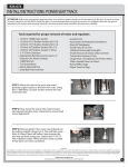
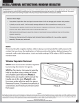
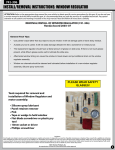
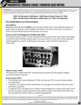
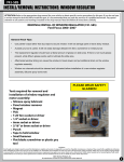
Installation Instructions RN064-516 Rev B INSTALL/REMOVAL INSTRUCTIONS: INTAKE MANIFOLD ATTENTION: Refer to the appropriate shop manual for your vehicle to obtain specific service procedures for this part. If you do not have a service manual or lack the skill to install this part, it is recommended that you seek the services of a qualified technician. Pay special attention to all cautions and warnings included in the shop manual. Read and follow all instructions carefully. Failure to do so will result in severe damage to the intake manifold and to the engine. REMOVAL/INSTALL OF INTAKE MANIFOLD 4.6 LITER V8 ENGINE GENERAL TECH TIPS: This updated manifold does not require additional intake gaskets. The intake gaskets are already installed into the manifold. Be sure to fully seat the injectors when installing the fuel rail. Failure to do so will result in a vacuum leak. To install fuel rail, first start all M6 self-tapping fasteners for three rotations. Tighten down (5Nm7Nm). (Not all self-tapping screws are used for every application). DO NOT OVERTIGHTEN! To attach ignition coils, use provided M5 self-tapping screws. Tighten down (2.7-3.3 Nm). DO NOT OVERTIGHTEN! The 4.6L engine was built at two different Ford plants (Romeo and Windsor). There were several cylinder head designs produced at these locations. Dorman has found that sometimes the original gasket alignment holes in the head were placed a position near or under our gasket’s centerline location; if you find this is the case, simply fill these holes with RTV prior to manifold assembly to avoid a vacuum leak. 1. Carefully remove intake manifold per the service procedure outlined in shop manual. 2. Clean mounting surface. 3. Use coolant cap spacer if required. (Gray arrow) Measure the step height of the coolant cap of the original manifold. Use included spacer if the shown coolant outlet height is 7.5mm or higher. This part is not necessary to use if the measurement is less than 7.5mm. 4. Use (2) coolant cap bolt spacers (White arrows) if the removed manifold coolant crossover is made of plastic. These parts are not necessary for aluminum crossover. 5. Install new intake manifold per shop manual. 6. Pre-install intake bolts. 7. Tighten intake bolts as follows in sequence shown below: Stage One: 2 Nm (18 inch lbs.) Stage Two: 25 Nm (18 ft. lbs.) Disclaimer: Even though every attempt is made to ensure this information is complete and accurate, it is impossible to account for all possible circumstances or situations. Please consult with a qualified auto technician before attempting to perform any work you are not qualified to do. Automobiles can be hazardous to work on; be sure to take all necessary safety precautions. Failure to do so may result in property damage or personal injury. Certain motor vehicle standards and performance requirements may apply to our motor vehicle (such as Federal Motor Vehicle Safety Standards by the National Highway Traffic Safety Administration). Be sure that your work is performed in accordance with such standards and that you do not disable any motor vehicle safety feature. 1