1
ENG
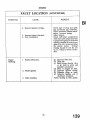
When a regrind is found to be necessary a
decision will have to be made as to the
suitable undersize bearings which will meet
the particular case. The reduced diameter
of journal to suit the various undersize
bearings may be calculated by subtracting
-.020", -.03OU or -.04OU, the sizes of
bearings available from the original dimensions on page 1.
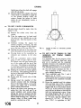
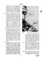
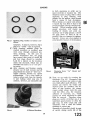
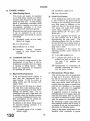
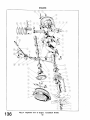
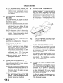
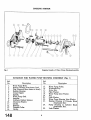
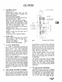
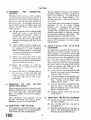
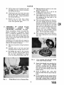
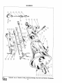
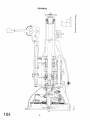
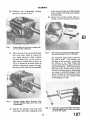
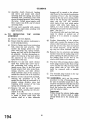
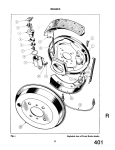
Fig. 15
Exploded view of Distributor and Tachometer Drive Details.
The main bearings are of the precision
type, bi-metal steel backed. No hand
fitting is required and in no circumstances
should the bearing caps be filed with a
view to taking up wear. The m n g of
bearing caps will make them unserviceable
for future use when new bearings are
ultimately used.
Where excessive bearing wear has occurred
the only satisfactory cure is to replace worn
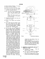
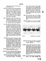
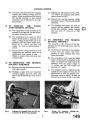
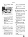
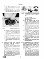
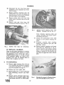
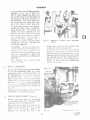
Fig. 16
Position of Slot in Distributor Boss when
No. H cylinder is at T.D.C. on compression stroke.
bearings ensuring first, however, that the
crankshaft journals and pins are in good
order and that there is no question of a
regrind being necessary. Where a crankshaft journal is worn, scored or tapered in
excess of .002" regrinding is necessary.
Main Bearing Clearance
The crankshaft journal diameter and
the internal dimension of the bearings
is given on page 1. The clearance new
for the main bearings is .001"-.0025",
if the worn clearance exceeds .006"
or if the journals have become scored,
the crankshaft will have to be reground and undersized bearings fitted.
The crankshaft should be measured
with a micrometer gauge and if the
reading is less than 2.477" (for a
crankshaft that has not previously been
ground) the shaft is due for reconditioning.
With regard to the main bearings,
when the worn internal dimensions
exceed 2.483" (for the standard size
bearings) replacements should be fitted
undersized to suit the amount which
has to be removed from the undersizes available, viz : -.010", -.020",
-.030" and -.04OU.
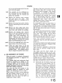
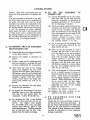
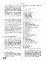
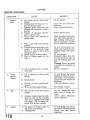
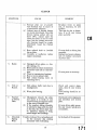
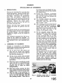
The: float specified for the crankshaft is
.004"-.006" when new,which shouldbe
measured as shown in Fig. 17. Where,
after the fitting of new thrust washers,
end float is below .004" the steel face
of the thrust washers should be rubbed
down on a piece of emery cloth placed
on a surface plate as shown in Fig. 18.
Do not reduce the white metal bearing
surface.
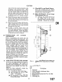
The illustration shows the en* float
being measured by the feeler gauge
method. An alternative method is the
use of a Dial Test Indicator which will
ive a more positive reading if the dial
as at 'c zero " when the crankshaft is at
of its float.
onsiderable mileage, wear may
occur on the face of the crankshafi
st washers. It may be
necessary to fit oversize thrust washers,
ENGINE
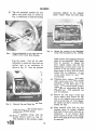
Fig. 18
Fig. 17
Measuring Crankshaft End Float. This
operation can be carried out with a Dial
Test Indicator.
and although this may rarely happen,
oversize thrust washers .OO5" may be
obtained by a special order on the
Spares Department under their normal
detail number specifying that the oversize thrust washers are required.
+
5.
CONNECTING ROD BEARINGS
(Fig. 8)
The connecting rod, a molybdenum manganese steel stamping, is provided with a
phosphor bronze small end bush and the
precision type lead indium bronze steel
backed bearing at the big end. Like the
main bearings, no hand fitting is necessary
and in no circumstances should the bearing
caps be filed to tdke up wear.
Where excessive journal wear has occurred
the only satisfactory cure is to replace the
bearings ensuring first, however, that the
crankshaft journals and pins are in good
order. Where a journal or pin is worn,
Reducing the thickness of a Thrust
Washer. This must only be carried out on
the Steel Side.
scored or tapered in excess of .0020" regrinding is necessary.
When a regrind is found to be necessary a
decision will have to be made as to the most
suitable undersize bearings which will meet
the particular case. The reduced diameter
of the pin to suit the various undersize
bearings may be calculated by subtracting
-.0100", -.0200", -.030OV or -.0400°
from the original size as listed on page 1.
The small end bushes, dimensions given on
page 2, should be pressed into the rods and
subsequently reamed to g" &.OOO5". A
gudgeon pin selected to give a clearance of
.0002" at 68°F. Thls clearance will be indicated by a light finger push fit, with the
piston warmed by immersion in hot water.
The connecting rod centres are 6.250"h
.002" and there is no offsetting of the rod in
relation to the bearing housings. The connecting rod cap is located in relation to the
rod by means of dowel bush, as shown in
Fig. 6.
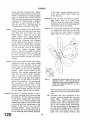
Before installing a connecting rod it should
be checked for alignment after first removing the bearing shells. The rod should
be checked for bend, in which the piston
will not be perpendicular to the crankpin,
or if the gudgeon pin is not on the same
plane as the crank pin the rod is twisted,
see Fig. 19. Appropriate action should be
taken to deal with the various causes of
misalignment with a suitable bending bar.
The connecting rod aligning fixture shown
in Fig. 19 is obtained from Messrs. V. L.
Churc
rnpany Limited.
ENGINE
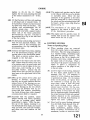
PISTON ASSEMBLY AND CYLINDER SLEEVES
The piston and cylinder bore dimensions
are given on page 2. As indicated in this
list of tolerances and limits, three sizes of
pistons are used in conjunction with suitable
bore dimensions. The three sizes of pistons
and cylinder sleeves are indicated by the
stamping of F, G or H on the crown of each
piston and the upper flange of each cylinder
sleeve as shown in Fig. 20.
Piston ring dimensions and clearances are
also given on page 2. Where the worn
clearance between the piston skirt and the
cylinder sleeve bore exceed .007" at the top
and .005" at the bottom reboring or replacement becomes necessary if a satisfactory repair job is to be executed.
The connecting rod should be fitted to the
piston assembb with its bearing cap towards the split portion of the piston skirt
T h e importance of using cylinder sleeve
retainers to prevent relative movement of
these parts is stressed.
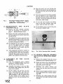
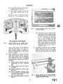
Fig.
20
The Identification Letters stamped on the
Piston Crown and the Cylinder Sleeves.
Note also the flats on the outer periphery.
When the sleeves are installed in the block
the flanged face should stand proud of the
cylinder block by .003!' minimum-,0055"
maximum, and checked as shown in Fig. 5.
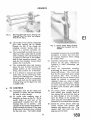
Fig. 19
The Churchill Fixture No. 335. Left-hand
examining for " twist."
Right-hand
examining for " bend."
and then should be assembled into the
cylinder sleeves with the gudgeon pin in
diametrical relation to pairs of opposite
flats on the upper flanged faces of the
cylinder sleeves. When assembling the
sleeve and piston into the cylinder block,
position the bearing cap of the connecting
rod towards the camshaft side of the engine,
or away from the point of maximum thrust.
When cases of light wear occur and cause
piston knock, an improvement can be
effected by withdrawing the sleeve and
rotating this 90" and so employ the alternate pair of flats as shown in Fig. 20.
FIGURE OF EIGHT JOINTS (Fig. 4)
These joints are between the lower flanged
e cylinder sleeves and the
machined recesses in the cylinder block.
They are metal and the plastic coating ensures that they afford a good water tight
joint. Failure <o do so will-mean that water
will leak from the cylinder block water
jacket into the sump.
It is essential that these joints are handled
and stored with great care to prevent
damage to the plastic coat.
These joints are fitted one to each pair of
cylinder sleeves. Before fitting, the sleeves
and block should be thoroughly cleaned
with a wire brush to ensure all scale and
foreign matter is removed, and a light
coating of " Wellseal " jointing compound
applied to both sleeves and block. Extreme
cleanliness is essential.
Sinking of the cylinder sleeves is prevented
by the use of these metal joints. The sleeves
should stand .003" to .0055" above the face of
the cylinder block and a routine check
should be made whenever the combustion
head is removed. Should the cylinder
sleeve(s) be below the specified limits new
figure of eight joints should be fitted.
NG GEARS
The camshaft is of cast iron, having chilled
faces for the cams and journals. With the
camshaft a cast iron fanged front bearing is
used, the other three journals making &rect
contact with the cylinder block.
In the near future it is
four Vandervel bi-metal
cornmodate the camshaft A recognition of
an engine so fitted with these bearings will
be that three setscrews retaining the three
rearmost bearings will e clearly visible on
the left-hand side of the cylinder block. The
front bearing is pressed into the front
bearing sleeve.
The camshaft is driven by a double roller
silent chain whch engages with a sprocket
on the crankshaft and one spigotted on the
offset from a tooth centre. When the chain
wheel is fitted at 90" to its initial position,
whch location we will identify as position
"A", a tooth of adjustment is obtained.
If on the other hand the wheel is turned
" back to front " from position "A"
a &
tooth of adjustment is obtained, whilst a
90" movement in the reversed position will
give d of a tooth variation from that given
by position " A."
When the timing has been correctly set the
faces of the two gears are marked with a
scribed line drawn radially in such a manner
that if the lines were produced outwards on
the respective gears they would pass through
e centres of the two gears.
In addition, to avoid any possibility of the
camshaft position being incorrect, a centre
punch mark is made on the end of the camshaft through an unoccupied bolt hole and
on the face of the timing gear adjacent to the
setscrew hole ; Fig. 21 shows the marking
of the
g wheels.
The h
gear for the hstributsr and
tachometer drive an
operating
the fuel pump are inte
ts of the
camshaft.
End float of the camshaft is taken between
the flange on the front camshaft bearings
and the rear face of the timing wheel.
h placed on a surface plate, to
e end float it will be necessary to
on the camshaft
end of the camshaft and secured by two
bolts.
Four holes are provide
timing gear, which are
e cylinder head as described
rhnising" and cc
ENGINE
sleeve retainers (Churchill Tool No.
S.138) should be applied as shown in
Fig. 22.
In the event of sleeve movement, new
figure of eight washers should be fitted.
Remove push rods and tappets.
( c ) Disconnect tachometer drive. Remove
distributor assembly complete with
pedestal by removing the two securing
nuts at the crankcase. Do not slacken
clamp bolt. Remove distributor and
oil pump helical driving gear.
(d)
. , Check that the pztroi has been turned
off, remove pekol pipe and pump.
(See "Fuel9' Section P.)
(e) Loosen off dynamo and remove fan
and fan assembly by withdrawing four
bolts and the extension bolt.
( f ) Remove the timing cover by withdrawing the seven setscrews, four
bolts and one nut. Note the timing
markings on the gear wheels and camshaft ; this will assist in the reassembly (see Fig. 21).
(g) Release the locking plate and withdraw the two setscrews. The timing
chain can be lifted off the chain wheel
and both components moved clear.
) T l x front camshaft bearing is next
removed by withdrawing the two setscrews and locking washers.
The
bearing can be lifted away.
(i) The camshaft can now be drawn
forward out of the cylinder block.
T
Re-assembly is the reverse procedure to the
Fig. 22
Showing one of the two Cylinder Sleeve
Retainers required to prevent movement.
removal. It is considered desirable to
describe certain operations as follows :hen resetting the valve timing, the
engine should be set with Nos. 1 and 4
pistons at T.D.C. In t h s position the
crankshaft timing wheel keyway is
pointing vertically downwards, as
shown in Fig. 21.
Rest the camshaft chainwheel on the
camshaft spigot and turn the chainwheel about the camshaft until the
identification punch mark on the end
of the camshaft can be seen through
the punch marked hole in the chainwheel. Secure the chainwheel to the
camshaft leaving the two bolts finger
tight.
Turn the camshaft chainwheel until
the scribe line rhereon aligns with the
scribe line on the crankshaft sprocket.
Without moving the camshaft remove the camshaft chainwheel and
when removed fit the timing chain to
this wheel and the one on the crankshaft in such a manner that the scribe
lines remain aligned. Reposition the
camshaft chainwheel and check by
simulating pressure of the chain tensioner that the timing marks have
retained their positions and re-adjust
if necessary. Tighten bolts to correct
torque loading and turn over tabs of
locking plates.
(b) When refitting the oil pump and distributor driving helical gear, ensure
that No. 1 piston is at T.D.C. on
the compression stroke. In this position the correct engagement of the
helical gear should allow the Woodruffe key to be positioned towards the
front of the engine, pointing approximately towards the d~pstick(Fig. 16).
It may be found that the oil pump,
shaft will not engage with the pump
for the tongue and slot of these coments are out of fine. The engine
need to be turned over slowly until
the shaft engages with the pump.
Continue to turn the engine until the
offset slot in the distributor drive boss
attains the position as illustrated in
Fig. 16. Disengage the helical gear
and remove it from the housing. Turn
the engine over until No. 1 piston
attains the T.D.C. position on the
compression stroke and replace the
ENGINE
helical gear when the shaft will engage
with the oil pump.
(c) Having refitted the cylinder head and
rocker shaft it. is advisable to apply oil
to the ground surfaces where the
rockers contact the valves, as these
points do not immediately receive a
supply of oil.
11.
TO SET VALVE CLEARANCES
All adjustments should be made when the
engine is cold,
Remove the rocker cover from the
engine.
Turn the engine over by hand until
the valves of any cylinder are on the
point of rock. Note the number of this
cylinder.
Continue turning the engine for
another complete revolution, this will
ensure that the tappets of this cylinder
are at the base of the cam (Fig. 23).
Holding the ball pin in the rocker arm
with a screwdriver, loosen the lock nut.
Pressing down on the screwdriver to
eliminate any slackness in the valve
gear.
Turn the screwdriver until a feeler
gauge of .01OV for inlet valve or .012"
for exhaust valve will pass between the
toe of the rocker and the tip of the
valve stem. The ball pin or screwdriver
is turned anti-clockwise to increase the
gap and clockwise to decrease the gap.
Holding the screwdriver steady, tighten
the lock nut. Still applying pressure to
the heel of the rocker check the gap and
adjust if necessary.
Repeat with the second valve of that
cylinder.
Having noted the number of this
cvlinder continue with the remaining
three in the firing order 1, 3, 4, 2, by
turning the engine half a revolution
before making adjustments.
Replace the rocker cover pressing, ensuring first that the cork seal is in
sound condition and second, when
placing the cover in position, that the
right-hand side does not foul the combustion head securing nuts. Failure to
observe either of these points may
result in a serious loss of oil.
I l I
I
Fig. 23
12.
Tappet on base or concentric position
of cam.
TO SET VALVE TIMING IN THE
ABSENCE OF TIMING WHEEL
MARKINGS
It is assumed that, for the purpose of this
instruction, the cylinder head and valve
gear are in position and the crankshaft
sprocket is keyed to the crankshaft but the
camshaft chainwheel has yet to be fitted.
The following procedure is recommended :
(a) Set valve rocker clearances for Nos. 1
and 4 cylinders to .015" which is the
valve timing clearances.
(b) Turn crankshaft until Nos. 1 and 4
pistons are at T.D.C.
This position may be found by placing
the keyway in the crankshaft vertically
downwards.
(c) Rotate the camshaft until the exhaust
valve and inlet valve of No. 4 cylinder
are at the point of balance in which the
tappets will be in the position shown
in Fig. 24. In this position the exhaust
valve will just be about to close and the
inlet just commencing to open. From
the timing diagram, Fig. 25, it will be
observed that the inlet valve opens at
15" B.T.D.C. and the exhaust valve
closes at 15" A.T.D.C. 15" before or
&er T.D.C. is equivalent to .081"
ENGINE
(2.06 mm.) piston travel or
1.5"
T.R.2. VALVE TIMING DIAGRAM
If the timing is correct the two
sions will be identical. Having h a l l y
proved the valve timing, the chainwheel
locking tabs may be turned up.
(i) The timing gears are now marked with
a scribe line as shown in Fig. 21.
(j> Fit the timing chain tensioner and
with plain washer and split pin.
e timing cover.
(L) The rocker clearances are now set to
their working clearances of .012" exhaust valve and .OIO1' for inlet valves
(see page 22). When the car is used for
high speed work the valve clearances
for all valves is .013".
13.
N
AND
D
See also "Engagement of
Distributor Driving Gear".
It is important that the ''
Tachometer Gear Assembly" is fitted with
an end float of .003" to ,007".
This can be measured in the following
manner :(a) Measure and note the thic
washer and assemble i
distributor-tachometer driven gear to
the oil pump driving shafi.
(b) Install this assembly in the cylinder
block with the washer between the gear
and the shaft bearing in the cylinder
block. Ensure that the shaft is engaged
in the oil pump.
(c) Over the gear assembly
butor adapter.
(d) Utilising feeler gauges, ascertain the
distance between the distri
ter and its mating face on
block.
(e) When this measurement is compared
with the thickness dimension of the
washer the difference will represent
the amount of "end float" or "interference".
.0601'
of washer
Distance between faces
.055"
The distance,
less than the
washer, gives
ar assembly an
" end float " o
Conversely
.06Ou
Thickness of washer
Distance between faces
The distance
washer, gives
'"interference" of .005". It will be
necessary to fit shims or packings under
the distributor adapter to obtain the
correct end float.
Assuming the first instance to be the
case, it will be necessary to add one
packing of .002" thickness to bring the
end float to top limit. For the second
instance it will be first necessary to
"zero" the interference, i.e., .005" and
add sufficient packings to obtain the
correct end float. The packing necessary
in this case is .011" for a middle limit
end float.
(f) Remove the gear assembly, shaft and
washer from the cylinder block.
) Turn the engine until the piston of No.
1 cylinder is at T.D.C. on compression
stroke, in this position both valves will
key to the oil pump
driving shaft and insert the shaft in the
age the oil pump with its
ate the shaft until the key
is at right angles to the camshaft and
oints away from the engine.
osition and lower the distributortachometer driven gear on the drive
shafi until the keyway and the key
engage. Continue a downward motion
turning the gear clockwise to effect
engagement with the driving gear on
the camshaft. Caution must be exercised to prevent dislodging the Woodruffe key.
(j) When correctly engaged the offset slot
ear assembly will be aligned
1 pushrod sealing tube- and
t towards the rear of the
engine. Similar to Fig. 16.
(k) Assemble the distributor adapter tonecessary packings to
the correct end float. Secure
uts and locking washers.
tor body with the rotor
No. l push rod tube.
ts to .015" and with the
contact pomts just commencing to separate the vernier adjuster on the third
marking of its scale, secure the body
to the adapter bracket with the nut and
a plain washer, under
) Advance the vernier a fu
n, which is equivalent
'fion 4"on the flywh
casting stresses to resolve themselves and
permits the consequent valve seat distortion ro be counteracted by valve
Failure to carry out this init
grinding is a frequent cause of excessive
petrol consumption of new cars. Subsequent attention will not normally be
required until further considerable amount
of running has been one-normally afier
about 15,000 miles.
The above mentioned 5
sideration a car which is used under
normal conditions.
for competition and
grinding is done as
The procedure recommended for decarbonising is as follows :(a) Disconnect the battery lea
leads from lug;^.
"
cooling system.
ct the fuel pipe clip, the top
water and bypass hoses and remove
the therm0 gauge bulb from the
thermostat housing, then remove the
latter from the cylinder head by withdrawing the two bolts.
ker cover securing
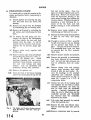
Fig. 26
Plug Lead Attachment Sequence.
attempt to break the seal of the cylinder head by turning the engine as this
will disturb the cylinder sleeves.
ustion head has
.z
ment and if any is suspected the
cylinder sleeves and pistons wdl have
to be removed and new figure of eight
joints firted.
Remove the push rods.
15.
orted, this will en-
rise as a unit.
) Remove the eater hose from the water
shut-off cock at the rear o f t
head. (Where heater is fit
(g) Disconnect the throttle and choke
controls, the suction pipe and fuel
en
fro
ENGINE
arises, it is important that the valve guides
are concentric with the seats themselves.
Where a valve guide is badly worn it should
be replaced before the seat is recut.
While refacing valves, only remove sufficient metal to clean up the face, otherwise
if too much is removed the edge will tend
to curl up in service.
Where valve seats are badly worn or pitted
they should be recut with an 89" cutter
utilising a pilot of the same diameter as the
valve stem. Should the valve seating become embedded in the cylinder head as
shown in Fig. 27, it will first become
necessary to employ a 15" cutter, to provide
a clearance for the incoming or outgoing
gases, following this with a cutter of 44kn.
This work should be carried out after the
cylinder head has been cleaned.
The valve and guide data is given on pages
3 and 4.
16.
REMOVAL OF CARBON
Remove the spark plugs, clean, set and test
ready for replacement. If for any reason
such as badly burnt or broken electrodes,
and damaged insulation the plug should be
replaced. For normal motoring Champion
LlOS 4" reach ; for high speed motoring
L1 l S reach is recommended and the gap
is to be set at .032". The normal life of a
spark plug is 10,000 miles.
Clean the carbon from the cylinder head,
finally wipe the chambers clean. Scrape the
valve ports clean, exercising great care not
to damage the valve seats. When the head is
clean of carbon blow out with a compressed
air line and wipe with a rag moistened with
petrol. Ensure that the contact face is
perfectly clean and flat.
Before cleaning the carbon from the tops of
the pistons, smear a little grease around the
top of the two bores and raise the piston
almost to the top. Fill the other two bores
and tappet chambers with non-flu@ cloth ;
this will safeguard against any carbon chips
entering the lower extremities of the engine.
It is suggested that the piston crowns are
cleaned, utilising a stick of lead solder,
which will not scratch the piston crown,
in such a manner that the carbon deposit
on the vertical wall of the piston and that
deposit formed in each cylinder bore
above the maximum travel point of the top
piston ring is not disturbed. This carbon
helps to insulate the piston rings from the
heat generated during combustion and
provides a secondary oil seal.
The use of emery cloth or other abrasive
for polishing is not recommended as particles of such abrasive may enter the bores
and engine after re-assembly, causing
serious damage.
Having cleaned two pistons, brush and
blow away the carbon chippings, taking care
not to allow any to drop into the cylinder
block. Lower the clean pistons in their
bores and wipe away the grease, remove the
cloth stuffing from the other two piston
bores and grease the tops. After greasing
the tops of the cyhder bore raise these
pistons and fill the remaining two bores
with the rag. Repeat the cleaning operation.
On completion of the piston cleaning, wipe
and blow away the carbon chips and clear
the block face, particularly around the
cylinder sleeves and the tops of these
+"
I
I
Fig. 27
A
"
Pocketed " Valve Seating.
sleeves. Clean the grease from the cylinder
bores and remove the cloth stuffing from the
bores and tappet chambers.
The valve springs should be examined for
damage and their length compared with
new springs. If any doubt exists as to the
condition they should be replaced. The
exhaust valve is fitted with an auxiliary
inner spring, making three springs in all.
It should be noted that the close-coiled end
of these springs is fitted nearest the cylinder head.
Ensure that the cylinder block and head faces
are perfectly flat and clean, it should only be
necessary then to apply a coating of grease
to the cylinder gasket. Should it be decided
to use a sealing compound, one of the nonsetting type must be used for on future
occasions when the head is removed, the
cylinder sleeves may be disturbed because
of their adherence to the gasket.
When refitting the cylinder head nuts,
tighlen them gradually in the sequence
shown in Fig. 28 in order to produce an
even pressure on the gasket and prevent
undue strain in the cylinder block casting.
It will be necessary to recheck the nut
tightness when cold to 100-105 lbs. ft.
Before tightening down the rocker shaft
pedestals, screw back each adjusting screw
and ensure that the ball ends of these
screws engage correctly in the push rods.
Failure to attend to this procedure can
result in damage to the push rods. Smother
the rocker gear with oil, particularly where
the rockers bear on the valves.
Before replacing the rocker cover ensure
that the cork joint is undamaged and
shellaced to the cover, otherwise oil may
leak through the joint.
After the first 500 miles the cylinder head
nuts should be checked for tightness with
the engine hot.
LOW COMPRESSION KITP m T NO.502227
This kit was introduced for those owners
who experienced difficulty in obtaining
fuels of a high octane value.
The kit comprises of :8 Push Rods (longer than those normally
fitted).
1 Combustion Head Gasket.
1 Low Compression Plate.
Corgasyl " Combustion Head Gasket.
Prepare the engine unit as for decarbonisation (see gage 25.)
No
attempt should be made to break the
combustion head seal by turning the
crankshaft-this action will only disturb the cylinder h e r s on their
lowennost seating and water leakage
will result. When the head has been
removed fit liner retainers (Fig. 22)
and check that the liners stand proud
of the cylinder block .003" to .0055"
(see page 19.)
Apply a light coating of " Wellseal "
jointing compound to both sides of the
low compression plate and gaskets.
Fit the copper cylinder head gasket
(smooth face downwards), followed by
the low compression plate and steel
" Corgasyl" gasket; this may be
fitted either side up.
(d) Fit the longer push rods and lower
the combustion head into position.
Omitting the plain washers, tighten
the combustion head nuts (Fig. 28) to
the correct torque (100 to 105 lbs. ft.).
(e) Screw back the ball pins in the rockers
and then fit shaft assembly to the corn-
Fig. 28
Cylinder Head nut tightening sequence
bustiox head and tighten nuts to 2426 lbs. ft.
Adjust valves for clearance. (See
page 22.)
( f ) Reconnect fuel pipe, carburettor/distributor suction pipe, throttle and
choke cables to carburettors.
(g) Replace rocker cover, ensuring first
that the seal is in good order, also the
thermostat housing, thermo gauge
bulb.
(h) Refit heater hose (if heater is fitted),
by-pass hose, top radiator hose. Replenish cooling system with coolant.
(i) Reconnect fuel pipe at pump. Connect battery lead.
NOTE-After
the first 500 miles the
cylinder nuts should be checked
for tightness with the engine hot.
18.
THE
PUROLATOR MICRONIC"
OIL FILTER -TYPE 17F.5102 pig. 29)
The Purolator Micronic filter consists of
a plastic impregnated paper element which
removes the finest articles of abrasive
which invariably fin their way into the
engine. A filter of this type will sto not
only the smaller microm sized partic es of
abrasive, but ensures a supply of clean oil
to the engine at all times. The only attention
which the filter needs is to see that the
element is changed at periods not exceeding 8,000 miles. It is essential that this
operation is carried out at specdied periods
F'
P
B
to ensure maximum filtration. T o renew
the element proceed as follows :(a) Clean the outside of the filter casing.
(b) Unscrew the centre bolt and remove
the filter casing and element.
NOTE-The paper element, its perforated
outer cover and element tube
forms a complete element assembly.
Ensure that the to^ seal is retained in position & the groove
in the filter head.
F I L T E R HEAD
-TOP
SEAL
F Y T E R E D OIL T O
SUMP
_ELEMENT
( c ) Withdraw the element and clean the
inside of the casing.
OUTER
(d) Insert a new element into the filter
casing.
(e) Fit the filter and new element to the
filter head ensuring that the spigot
formed on the head enters the centre
tube of the element squarely. Tighten
the centre bolt sufficiently to ensure an
oil-tight joint. (14-16 Ibs. feet.)
un the engine for a few minutes and
inspect the filter for leaks. If leakage is
noted between the filter casing and the
head, the centre bolt must be unscrewed and the casing and element
withdrawn. A new top seal should then
be fitted. If leakage occurs at the
bottom of the filter, wirhd
casing and element, remove
clip from the centre bolt and
the bolt from the casing ; c
element support, bolt seal, washer and
spring. Ease the remaining seal out of
the bottom of the casing and fit a new
seal in its place. Insert the centre bolt
and fit the spring, the washer, a new
bolt seal and the element support on to
the part, fit circlip into its groove in the
bolt. Place the element inside the
casing and offer up the
filter head, screw the ce
A certain quantity of oil
to the removal of the filter casing, and
the sump should be topped up after
assembly of the filter.
The filter casing should not be disturbed until element renewal is required. T o do this invites the hazard
that the accumulated dirt on the outside of the filter may be allowed to
contaminate the inside; thus being
CIRCLIP
BOLT S E A L
,
ELEMENT
WASHER /----
C E N T R E BOLT-----
SPRING
8
-"'
Fig. 29
The Purolat~rOil Filter.
carried into the bearings when the
ine is re-started.
Do no attempt to reset the pressure
relief valve which is incorporated in the
filter head. This is the main engine
pressure relief valve and is set at the
works to a predetermined figure.
(a) Disconnect the battery. Turn off
etrol at shut-off cock.
) The bonnet is removed by removing
four hinge nuts, two at each hinge.
(c) Brain off the cooling fluid by opening
the taps, one at the base of the radiator
and the second situate
and exhaust manifold
block.
e oil from the en
gearbox.
Disconnect the hea
cables at their snap connectors. Remove the bolts fiom the top brackets
and the bolt in the centre of the
this holds the bonnet lock
connecting cable, release cable control
at one side. Remove th
handle bracket and the
from under the cowling a
nut and bole from the st
) T o remove radiator disconnect top
and bottom hoses, ease the tie rods
S one either side
) Discorinect the lever
at [he
ect the
foremost carburettor ;
h e r and outer cables of the choke
el feed pipes at their
e the carburet-
four nuts-two at eac
Remove the
by first rem
(two to each hor
to chsconnect the horns from their
cables. Disconnect dynamo leads and
remove dynamo fro its bracket and
remove fan belt.
Rernove front chassis cross tube
removal of three nuts and bolts at each
flange.
Remove the three nuts and washers at
the exhaust flange and break the joint.
ee the rubber gear lever grommet by
e removal of three self-tapping
screws from the gearbox cover pressing
and remove the latter by unscrewing
the thirteen setscrews, hidden by the
trim and floor covering.
(n) Remove the gear lever with grommet
by loosening the locknut and un-
go) Remove the speedometer drive, the
overdrive cable at the snap connector
and the starter motor by removing two
nuts and bolts.
) Drain the clutch hydraulic system.
Disconnect the bundy tubing at the
flexible hose at the left-hand side
chassis member whilst holding the
hexagon on the hose. Still holding the
hexagon remove the ho\c securing nut
and shakeproof washer ; the flexible
hose can now be withdrawn from its
bracket.
) Uncouple the propeller shaft by removing the four
S and bolts securing
the two flanges.
move the two nuts
holding the gearbox to the chassis
frame.
emove the four nuts and bolts (two
each side) securing the engine mountings to the chassis.
(S)
Fit slings to engine and lift out in a
nose up " position, as shown in
Fig. 31.
66
Disconnect the
the petrol tap, t
pipe, starter motor cable, LT. lead at
the coil, the tachometer
distributor pedestal and with
water temperature gauge bulb.
T o remove the seats, rst remove the
cushions and unscrew the six
eight to each seat) thus rele
rame from the m e r s ; it can then
be lifted out.
i
. 30
The front of Car prepared for
Gearbox Removal.
DIS
It is sound policy to clean the exterior of the
engine and gearbox before commencing to
Qsmmtle.
(i) Detach gearbox by removing the nine
nuts and bolts from the clutch bell
housing.
(ii) Remove the clutch from the flywheel
by withdrawing the six searing bolts.
(E)
Remove the flywheel by unlocking the
-tab- washers and withdrawing the four
bolts.
T o remove the he1 pump, first $isconnect the pipe to the carburettors
and then remove the nuts and lock
washers from the studs. It will be
noticed that the rearmost stud accommodates the oil pressure gauge pipe
clip.
Remove rocker cover, together with
oil filler cap.
Remove suction pipe from distributor
and sparlung plug leads, H.T. and LT.
leads at the ignition cod. Avoid
loosening clamping bolt and remove
distributor from pedestal, secured by
two nuts with locking and plain
washers. Lift out disrributor and
tachometer driving shaft assembly.
(vii) Remove the ignition coil.
(viii) From the front of thermostat housing
remove the nut holding the clip for the
Fig. 31
The Engine and Gearbox being removed
from the Chassis. Note the " nose up '"
attitude.
fuel and suction pipes ; these two
pipes are strapped together and can be
lifted away. Remove the by-pass hose
from the thermostat housing to the
water pump housing after undoing the
two hose clamps. Withdrawthermostat
housing as a unit following the removal of the two bolts and lock
washers securing it to the combustion
head.
(h)Remove water purnp impeller after
withdrawing one bolt and two nuts.
Remove the water purnp housing which
is held by two bolts and spring
washers.
(xi) Procqed to remove oil filter assembly
by fiJst removing the cap nut holdmg
the-oil pressure pipe banjo to the
filter. This pipe can now be detached.
The remaining three bolts can then
be removed and the filter assembly
taken away.
Remove dynamo bracket and pedestal.
Remove fan assembly by withdrawing
four bolts, followed by the extension
bolt ; the hub and hub extension can
now be withdrawn from the crankshaft.
Remove timing cover and packing,
remove chain tensioner after withdrawal of split pin and washer. Observe the m a r h g s on the camshaft
chainwheel and crankshaft sproclyt
which should correspond to Fig. 21
when No. 1 piston is at T.D.C. of
compression stroke.
Release the tabs of the locking plate
and withdraw the two bolts to release
camshaft chainwheel, the chain can
now be freed from the crankshaft
sprocket. Camshafi chainwheel and
chain can now be lifted away and the
crankshaft sprocket and W o o M e
key removed from the crankshafe,
followed by the shims.
L f i rocker shaft assembly by removal
of the four pedestal nuts.
Remove the inlet and exhaust manifolds by removing eight nuts and six
clamps.
(xviii)Remove combustion head by removal
(X)
ENGINE
of ten nuts and washers and lift out the
push rods and tappets.
(xix) T h e camshaft can be withdrawn by
first removing two bolts securing the
front bearing, then the bearing and
finally the camshaft.
(xx) Remove the nineteen sump securing
bolts and remove the sump. Care
should be taken not to damage the oil
pump filter.
(xxi) Remove oil pump from inside cylinder
block by unscrewing the three nuts and
washers.
(xxii) Remove the front engine plate from
the block by removing the five attachment bolts, and discard the packing.
(xxiii) Remove the bearing caps, bottom
halves of the shell bearings and thrust
washers by releasing the tabs of the
locking plates and withdrawing the
bolts.
Remove also the big end
bearing caps and bottom halves of the
shell bearings by releasing the locking
plates and withdrawing the bolts.
(xxiv) Lift out the crankshaft and collect the
upper halves of the shell bearings.
(xxv) Collect the upper halves of the big
end shell bearings and withdraw the
connecting r o d s and pistons from
cylinder block. T h e cylinder sleeves
may be tapped out gently from below.
21.
RE-ASSEMBLY OF ENGINE
When the engine is completely dismantled
the following procedure is suggested for
re-assembly.
T h e cylinder block and combustion head
should be examined for leakage at the
various core plugs. If these do show signs
of leakage they must be renewed, their
seatings thoroughly cleaned and new plugs
fitted with jointing compound.
T h e main and big end journals of the
crankshaft should be checked for wear
against the dimensions listed on page 1.
Wear in excess of .0025" on the crank pins
and the journals should be met by regrinding, but where the bearing alone is
seriously worn (in excess of .003") its
replacement should suffice.
T h e bores of the sleeves should be measured
and if more than .010" in excess of the
dimensions quoted on page 2 they should
be renewed. It should be noted that
maximum wear occurs at the top of the bore.
The camshaft and camshaft bore should
also be dimensionally examined. Journal
wear in excess of .003" will necessitate a
replacement shaft, whilst wear in the
cylinder block bores of more than .0035"
will entail a replacement block.
It is intended in the very near future to
introduce replaceable camshaft bearings
for all journals. At the time of going to press
full details are not available and this matter
will be dealt with in an issue of "Service
Information."
The combustion head should be examined
and due attention paid to valve guides,
valve seats, valve springs and the valves
themselves. Valve guides should be replaced if they are more than .003" oversize
their original dimensions quoted on page 3.
Valve seats should be ground in, or if
"pocketed" (Fig. 27), new seats should be
shrunk in.
Valve springs should be thoroughly examined
for cracks and dimensions compared with
those quoted on page 5.
Valves should be examined to ensure that
their stems are prefectly straight and the
faces recut.
The block and the head should be
thoroughly cleaned or blown out by compressed air to ensure that all foreign matter
has been removed. Bolts, setscrews and
nuts are to be tightened to the torque
loadings given in General Data Section.
All joint washers, gaskets, locking washers,
lock plates and spht pins must be renewed
(i) Check that the two halves of the rear
oil seal bear the same number (Fig. 32).
These are machined as a mated pail
and failure to observe this instruction
may result in oil leakage. Shellac the
top half of the oil seal and attach it
loosely to the cylinder block by its four
bolts and lock washers. Shellac and
similarly fit the lower half of the oil
seal to the rear bearing cap. Ensuring
that the crankshaft mandrel is clean
(Fig. 33), lay it in the rear bearing
housing (without the shell bearings).
ENG
RECESSED FOR
BEARING HOUSING
-
-I
1
position.
Fit the lower halves of the main
s to the bearing caps, and
top halves of the thrust
side of the centre main
earing between the cra
cylinder block.
It is essential that the white metal
lightly secure with the two bolts and
lock washers to cylinder bloc
block with two bolts and
ashers each.
e front of the
engine, tighten the bearings cap bolts
to the correct torque (see '<General
Data"). On tightening %herear bearing
Fig. 33
DIAMETER OF
OIL SEAL
Crankshaft
andrel for centring t
Rear Oil Seal.
be tightened down so that the oil seal
shaft end float by the
auges or by using the
dial indicator gauge as shown
17- Should the end float dete
be greater than .006", thicker
e fitted; when the float
4", thmner washers are
xisting ones should be
own the two cheesedriver. Check tha
the two cavities, one either end of
with the sealing
C.
cap,
joint
n the absence of a crankshaft
h e oil
tta
loose
S i
the
either side of the rear main bearing cap
with the aid of a &" square brass
drift (Fig. 35). Two lengths about 9"
long are necessary. Completely fill the
groove and cut the felt off hi'proud of
the cylinder block face. It is suggested
that the felt strip is cut into approximately $" lengths for easy insertion.
Check the connecting rods for alignment in the Churchill Tool No. 335 or
a similar tool. Press the Clevite bush.
into the small end of the connecting rod
and ream out whlst in position using
the Churchill Tool No. 6200A and
reamer ; dimensions are to be found
on page 2. Assemble the piston to the
connecting rods so that the split of the
skirt faces the cap side of the rod
(Fig. 7). It is suggested that the
pistons be first submerged in hot
water for a few moments and the
gudgeon pin should then be a light
push fit. Secure the
with circlips, one either side. Dry the
piston and rod assemblies thoroughly.
Fit the piston rings to the pistons, the
two compression rings are uppermost
with one oil scraper ring below. Lubricate freely. Move the rings so that
their gaps ire 180' removedvfrom one
another ; failure to observe this point
may lead to increased oil consumption.
Wire brush the exterior of the cylinder
liners to ensure that they are free
from scale and all loose dirt on their
machined surfaces. With the assistance
of a piston ring compressor fit the
piston assemblies to the cylinder
sleeves bearing the same letter as the
piston.
Arrange the piston and connecting rod
assemblies now in their cylinder
sleeves, so that the numbers stamped
on the rods and caps run consecutively,
i.e., 1, 2, 3, 4. Turn these assemblies
upside down in pairs, 1 and 2, 3 and 4,
with the flat of the liner adjacent to
one another. The bearing caps are now
all uppermost and must be turned face
one way. Remove the bearing caps and
fit the shell bearings to rods and caps.
Fit one figure of eight packing, using a
light coating of " ellseal " jointing
compound on the flanged faces of each
Fig. 35
Sealing Rear Main Bearing Cap.
air of cylinder sleeves and on the
mating faces in the cylinder block after
ensuring that all components have
been thoroughly cleaned of all loose
deposits and the machined surfaces in
which the cylinder sleeves spigot are
clean and free from burrs, the sleeves
with their respective piston assemblies
can now be fitted to the block.
(xii) Locate the cylinder sleeves and piston
assemblies in the cylinder block so that
the cap of the connecting rod is adjacent to the camshaft side of the
engine. The assembly which bears
the number 1 on its connecting rod is
fitted to the foremost position. The
sleeves should stand .003" to .0055"
proud of the cylinder block face (Fig.
5).
(xiii) It is essential that means are employed to prevent the cylinder sleeves
from moving in the block. Messrs. V.
L. Churchill & Co. Ltd. have manu-
ENGINE
factured special retainers for this purpose (Fig. 22) and it is suggested that
these are employed. Until this is done
the piston assemblies must not be
moved, for any movement will be
transferred to the sleeve and damage
the figure of eight washers. If damage
is undetected, water leakage will result.
An alternate method is to insert the
cylinder sleeves alone into the block,
clamp them with the Churchill sleeve
retainers to ensure no further movement and then fit the piston assemblies
similarly as described in paras. (X) and
(xi).
(xiv) Having the sleeve retainers in position,
the connecting rods may be fitted to
the crankshaft, Nos. 1 and 4 cylinders,
followed by 2 and 3 cylinders. The
caps are fitted to their respective rods
and in such a manner that the tubular
dowel will sink into its recess and their
identification numbers coincide. It
should be noted that the bearing cap,
because of this dowel, can only be
fitted one way round. The cap is
secured by two bolts and a locking
plate. Tighten the bolts to the correct
torque loading and turn over the tabs
of the locking plates.
(xv) Push the oilite bush into the centre of
the crankshaft at its rear end and tap
the flywheel locating dowel into gosition in the flange.
(xvi) Fit flywheel located by/ the dowel so
that the arrow marked on its periphery
lines up with the centre of the cylinder
block with Nos. 1 and 4 pistons at
T.D.C. Secure flywheel with the four
setscrews and two locking plates, then
turn over the tabs of the locking plates
when the setscrews have been tightened
to their correct torque loading.
(xvii) Utihsjng jointing compound affix the
front plate packing and locating the
engine plate o n the two dowels secure
with the five bolts and locking washers.
Fit the engine mountings secured by
two nyloc nuts.
(xviii) T o the forward end of the crankshaft
fit the, sprocket locating shims, the
Woodrufie key and the sprocket wheel.
(xix) Lubricate the camshaft and feed into
the cylinder block and secure the front
bearing with two setscrews. Check the
end float as described on page 17.
Rest the camshaft chainwheel on the
camshaft spigot and turn the chainwheel about the camshaft until the
identification punch mark on the end
of the camshaft can be seen through
the punch marked hole in the chainwheel. Secure the chainwheel to the
camshaft leaving the two setscrews
finger tight. If a replacement chainwheel is being fitted, see "12. T o set
Valve Timing in the Absence of Markings" (page 22). Check the alignment
of the chainwheel with that of the
sprocket on the crankshaft, taking into
consideration the end float of the camshaft. The alignment can be adjusted
by altering the thickness of the shim
between the crankshaft sprocket and
the abutment on the crankshaft.
(xx) Turn the camshaft chainwheel until
the scribe line thereon lines up with
the scribe line on the crankshaft
sprocket. Without moving the camshaft remove the chainwheel and when
removed fit the timing chain to this
wheel and the one on the crankshaft.
Reposition the camshaft chainwheel
and check by simulating pressure of
the chain tensioner that the timing
marks have retained their positions
and re-adjust if necessary. Tighten
bolts to correct torque loading and
turn over tabs of locking plates. Lubricate tappets and place in tappet
chambers.
(xxi) Fit the chain tensioner to its pin and
secure with washer and split pin.
Screw in timing cover support bolt to
the engine plate and fit the oil deflector to the crankshaft so that the
raised edge faces the timing cover.
(xxii) Press the oil seal with its lip inwards
into the timing cover and fit this cover
with its packing to the engine plate
utilising one nut, eleven bolts with
four nuts.
NOTE-See that the short earth bonding strip from engine to chassis frame
is attached under the head of the bolt
which aligns with L.H. rubber mounting attachment nut.
The machined faces on the combustion
head and the upper flanges of the
cylinder sleeves; which contact the
combustion head gasket, should be
lightly coated with " Wellseal " sealing
compound. A substitute compound,
which retains its plasticity, may be
used if " Wellseal" is not available.
This sealing is necessary to ensure a
proper life for the gasket.
Assemble the valves and springs to the
combustion head (see " To Decarbonise," page 25) aid fit the assembly
to the block, tightening the ten nuts
and washers down as shown in Fig.
28. Fit push rods in the chambers.
Assemble the rocker shaft as follows :
To the rocker shaft fit No. 4 rocker
pedestal in such a manner that the oilfeed holes coincide and secure with
setscrew. To the shorter end of the
shaft, fit No. 8 rocker, a double coil
spring washer and a collar. Secure the
collar to the shaft with a mills pin. On
the longer end of the shaft feed the
remaining rockers, springs and pedestals (see Fig. 36). After fitting No. l
rocker, fit the double coil spring and
collar securing the latter with a mills
pin.
(xxvi) Loosen the ball pins and fit rocker
shaft assembly to combustion head
securing the pedestals to the studs with
four nuts and s p r i ~ gwashers. Before
exerting any pressure on the nuts it is
recommended that the adjusting pins
are slackened off to prevent them
coming into too hard a contact with
the push rods. Tighten down the nuts
progressively to the correct torque
loading (see "General Datay'SectionA).
(xxvii) Adjust valve clearances. See "1 1. To
Set Valve Clearances" (page 22).
(xxviii) Fit the oil pump assembly and packing
secured by three nuts and lockwashers
to the inside of the cylinder block.
(xxix) Fit the sump and packing to the cylin-,
der block and secure with nineteen
bolts and lock washers. The shorter
bolt is fitted through the front flange
of the sump into the sealing block.
The rearmost bolt on the left-hand side
accommodates the breather pipe clip
and the bolt in front of this accommodates the clutch slave cylinder stay.
When an aluminium sump is fitted,
two packings are used, one either side
of the tray.
(xxx) Fit the breather pipe to the cylinder
block and secure the clip to the sump
plate by the bolt, nut and lock washer
with a distance piece between the two
plates.
(xxxi) Fit ignition coil to side of cylinder
block with two nuts and lock washers.
Fig. 36
The Rocker Gear Assembly.
(xxxii) Fit distributor and adapter as described
in "13. Ignition and Distributor
Timing" (page 24).
(xxxiii) To the pulley hub and hub extension
assemble the fan pulley in such a
manner that the T.D.C. indicating hole
in the pulley is diametrically opposite
the key way in the pulley hub centre ;
secure with six nuts and bolts locked in
pairs with locking plates. On later
production cars with engine numbers
after T.S. 4145E the locking plate and
nut was replaced by a plain washer and
nyloc nut.
(xxxiv) Fit the Woodruff key to the crankshaft,
offer up the pulley assembly and
ENGINE
secure with the extension bolt. Shims
are placed behind the head of this bolt,
whch incorporates the starting handle
dogs, to provide the correct relation
with the starting handle and the engine
compressions. This position is obtained
with Nos. 1 and 4 pistons at T.D.C.
and the dog faces corresponding to
"10 minutes to 4 o'clock') (Fig. 37).
(xxxv) T o the fan assembly fit the split rubber
bushes (four front and four to the rear)
and slide into the bushes the four
metal sleeves. Place on top of the
rubber bushes four larger diameter
plain washers, the lockwasher for the
starting dog extension bolt dbllowed
by the balance piece placed in such a
manner that the drilled holes coincide
with the drill spot on the hub extension
'1.0 the securing bolts fit the locking
plates and smaller diameter plain
washers and feed through the holes
in the fan blade assembly, and offer up
the hub assembly to the crankshaft
and secure, finally turning over the tab
washers.
(xxxvi) Using a new joint washer and sealing
compound, offer up the water pump
housing to the cylinder block and
secure with two bolts and lock washers
and tighten to the correct tightening
torque. Affix a joint washer to the
housing with sealing compound and
offer up the water pump impeller.
This is secured by two nuts with lock
washers and a bolt with lock washer,
the purpose of this bolt is twofold, it
secures the impeller to the housing and
the housing to the cylinder block.
Attach the adjusting link with a bolt
and tab washer to the right-hand side
of the water pump housing but leave
the bolt finger tight at this juncture.
(xxxvii) Fit the "U" dynamo bracket to cylinder block utilising three setscrews and
lock washers. Fit the dynamo pedestal
to the front engine plate and secure
with nyloc nut ; offer up dynamo and
secure finger-tight to the pedestal with
a setscrew and lock washer and to the
bracket at the rear by nut and bolt
with lock washer. Secure the front of
the dynamo by its second h n g point
to the adjusting link (already attached
to the water pump) utilising one setscrew with a plain washer either side
of the dynamo.
it the fan belt and adjust to give 2"
play either side of a centre line.
Tighten up all nuts and bolts securely
including the bolt of the adjusting link
and turn up tab of tab washer.
(xxxix) Fit thermostat housing and packing
to combustion head and secure with
two bolts and lock washers, leaving
finger tight at this juncture. Connect
Fig. 37
Setting the Hand Starter Dog at Yen
minutes to four". Note also the hole in
fan pulley and pointer on timing cover,
which when aligned bring Nos. I and q
pistons to T.D.C.
the water pump and thermostat housing
with the by-pass hose and tighten hose
clips.
(xl) Assemble the inlet manifold to the
exhaust manifold leaving the two nuts
finger tight. Position the manifold
gaskets on the eight studs fitted in the
cylinder head. Fit the manifold assembly to the cylinder head, positioning
the four short clamps on the upper row
of studs and the longer pair on the two
inner studs of the bottom row. Fit the
eight nuts and spring washers and
ENG
tighten to 20-24
Ibs. ft. Finally
tighten the two nuts attaching the inlet
to the exhaust manifold to 16-18 lbs.
ft..
Fit the Purolator oil filter with packing
to left-hand side of cylinder block. I t
is located by a tubular stud and secured
by three bolts with lock washers. The
tubular stud accommodates the oil
pressure gauge pipe. This part is
fitted to the stud with a copper washer
either side of t e banjo connection
and secured by a cap nut. T h e pipe is
also attached by a clip to the rear stud
of the fuel pump.
(xlii) Fit fuel pump and packing and secure
with two nuts and lock washers. The
rearmost stud of this mounting also
accommodates the clip steadying the
oil pressure pipe.
(xliii) Connect fuel pipe from pump, clipping
it to the thermostat housing, also the
suction tube to the distribution union.
The latter, a narrow section tube, is
strapped to the fuel pipe.
iv) Apply oil to the rocker arms and valve
tops. Ensure that the rocker cover seal
is in position and is in good order and
secure cover to top of engine by the two
nyloc nuts, each bearing on a fibre
and plain washers. Ensure that the
r cover does not foul the cylinder
nuts at the right-hand side of the
engine.
(xlv) Offer up the clutch driven plate and
el, ensuring first
d condition and the
release levers of the housing are correctly adjusted. (See "Clutch" Section.)
Settle the housing on the two dowels
and secure the flywheel with six setscrews and lock washers, centralising
the clutch driving plate with a dummy
constant pinion shaft or mandrel.
(xlwi) Ascertain that the gearbox, clutch
release bearing and clutch operating
shaft are in working order before
assembling to engine. Offer the gearbox up to the engine, locating it on
two dowels and three studs, and secure
with six bolts, nuts and lock washers,
and three nuts and washers on the
studs.
(xlvii) The engine and gearbox can be fitted
to the chassis with the use of a derrick
or moveable crane. Allow the rear
extension of the gearbox to be lower
than the sump and by slowly lowering
the whole unit the mounting points can
be found ; utilise a rope sling fitted as
shown in Fig. 31.
(xlviii) The attachment of the engine and
gearbox to the chassis is the reversal
of the detachment procedure.
(xlix) The engine and the gearbox must be
refilled with oil and the radiator with
water before the car is used.
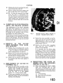
IGNITION SYSTEM
Notes on Sparking Plugs
When sparking plugs are removed
from the engine, remove their gaskets
with them. Place the plugs and gaskets
in a suitable holder, identifying each
plug with the cylinder number. The
tray shown in Fig. 38 is a simple construction with holes drilled to admit
the upper ends of the plugs. Place a
new plug of the proper type beside the
others to afford a comparison of
relative condition of the plugs in use,
to the new plug.
Look for signs of oil fouling, indicated
by wet, shiny, black deposit on the
insulator (Fig. 39). Oil pumping is
caused by worn cylinders and pistons
or gummed-up rings. On the suction
stroke of the piston, oil vapour from
the crankcase is forced up past the
worn rings, where it fouls the plugs
and causes sticking valves, with resultant waste of petrol. On the compression stroke, the mixture of oil and
petrol vapour is forced past the rings
into the crankcase again, contaminating
the oil and turning it black with carbon.
Carbon deposists in the combustion
chamber are formed from burning oil
vapour and cause " pinking."
Next, look for petrol fouling indicated
by a dry fluffy, black deposit (Fig. 401
This is caused by many things faulty carburation, ignition system,
defect in battery, dstribution coil or
condenser, broken or worn-out cable.
ENGINE
The important thing is for the petrol
consumption to be improved. If plugs
show suitability for further use, proceed
to clean and test.
means of the copper gasket between
the plug and the cylinder head. Plugs
not down tight can be easily overheated, throwing them out of the
proper heat range, causing pre-ignition,
short plug life and bringing about socalled " pinking." Don't tighten plugs
too much-but be reasonably sure a
good seal is made between plug and
cylinder head. Lower left shows a
gasket on which the plug was pulled
down too tight, or had been too long iq
service. Note the distorted condition.
Note evidence of blow-by, also a
cause of plug over-heating and resulting dangers. Upper right shows a
reasonably compressed gasket giving
the plug adequate seal and a good path
for heat dissipation. All may be compared with the new gasket, at lower
In preparing for cleaning, remove plug
gaskets, and in doing so ascertain their
Fig. 38
Sparking Plugs in a tray ready for
comparison.
condition. Note the gaskets illustrated
in Fig. 41. Upper left shows a gasket
not properly compressed. A large proportion of the heat from the insulator
is dissipated to the cylinder head by
Fig. go
Petrol fouling indicated by a dry fluffy
black deposit on the Insulator.
right. If gaskets are at all questionable
they should be replaced by new gaskets.
(e) Occasionally a blistered insulator or
Fig. 39
Oil fouling indicated by a wet shhy
black deposit on the Insulator.
baldy burned electrode may be noted
when examining plugs (Fig. 42). If
the plug is the type normally recommended for the engine and was correctly installed, i.e.? down tight on the
gasket-the condition may have been
brought a b u t by a very " lean "
mixture, or overheated engine. It is
well to remember that plugs operating
in the condition described above are
often the cause of poor engine perfonnance and extravagant petrol con-
ENGINE
in both operations in order not to
injure electrode or insulator tip. The
threaded section of plug shell is often
neglected in plug cleaning, even
though, like the gaskets, these threads
form a means of heat dissipation.
When threads are coated with carbon,
it retards the even flow of heat to the
cooling medium, thereby causing overheating. (When installing plugs, this
simple procedure will ensure no
binding of threads and avoid unnecessary use of plug spanner.) Screw
the plug down by hand as far as
possible, then use spanner for tightening onlv. Alwavs use a box manner to
avoid possible fracture of the insulator.
V
Fig. 41
Sparking Plug Gaskets in various conditions.
sumption. I t may be, however, that a
plug of a " colder " type is required.
After cleaning, examine plugs for
cracked insulators or insulator nose
worn away through continued previous cleaning.
In this case we
should recommend that the plugs
have passed their point of useful life
and new plugs should be installed.
Look for a deposit on the insulator,
under side electrode, which may accumulate heat and act as a " hot spot "
in service.
After cleaning and blowing surplus
abrasive out of shell recesses and off
plug threads by means o f " blow out "
nipple-examine
threads for carbon
accumulation. Use a wire brush to
remove carbon and clean the threads.
A wire buffing wheel may also be
utilised ; however, use reasonable care
Fig. 42
A Blistered Insulator.
i
Champion Series
Tester Unit.
"
700 " Cleaner and
Next, we are ready for resetting the
electrodes (Fig. 44). Remember that
electrode corrosion and oxides at gap
area vitally affect spark efficiency. Thk
cleaner can remove the oxides and
deposits from the insulator, but because of gap location, the cleaner
stream cannot always reach this area
with full effect, also, the tenacious
adhesion of corrosion, etc., would
require too much subjection to clean
blast for removal. Therefore, when
plugs are worthy of further use, it is
sometimes good practice to dress the
gap area, on both centre and side
electrodes, with a small file before
resetting to correct gap.
Resetting of electrodes should be part
of service during useful life of -the
ENG
plugs. However, the strains of intense
heat, pressure, mechanical shock, electrical and chemical action, during
miles of service, wreak suck havoc on
the electrodes that molecular construction is affected. Plues reach a
worn out condition and refetting can
serve a good purpose only for a time.
evidence of your careful handling of
the plugs.
) The top half of the insulator is often
responsible for causes of poor plug
Fig- 45
Fig. 44
The Champion Spark Plug Gap Tool.
Testing for Leaks.
performance (Fig. 47), namely, paint
splashes, accumulation of grime and
dust ; cracked insulators caused by
slipping spanner, or overtightening of
teminals. Examine for cracked insulators at shoulder and terminal post.
Remove grime and dust. Recommend
inspection, cleaning and testing every
3,000 miles (Fig. 48).
Clean and replace sparking plugs
periodically as necessary. The correct
gap for the TR2 plugs should provide
When gaps are badly burned, it is
indicative the plug is worn to such
an extent that further use is unwarranted and wasteful. When resetting, bend the side wire only, never
bend centre electrode as this may split
the insulator tip.
Inspect for leakage after testing, by
applying oil around the terminal (Fig.
45). Leakage is indicated by the presence of air bubbles, the intensity of
which will serve to show degree of
leakage. Leakage throws the plug out
of its proper heat range, as the hot gas
escaping has a " blow torch " effect on
the plug, causing compression loss,
pre-ignition, rapid electrode destmction and overheating of the insulator
tip.
(j) New gaskets have been fitted to the
plugs and the general improvement in
appearance is apparent now that the
plugs are ready to be installed in the
engine (Fig. 46). It requires no
imagination to know that improved
engine performance, ben'' petrol 'Ons ~ p t i 0 nand satisfaction will result.
The use of the stand (as illustrated) is
pig. 6
Sparking Plugs ready to fit to Engine.
the New Gaskets and the use of the
d.
a gap of .032", the C
4"reach plug being specified for normal
road work, the L l l S for high speed
work. The normal efficient life of a
sparking plug is 10,000 miles, after
which, if full efficiency and economy is
desired, the plugs should be replaced
by new ones of the type specified.
a piece of carborundum stone, so that
the points are closed they fit
against each other. If the points
have become seriously worn they
should be replaced by new items. The
points shoufd be properly set to
vide a gap of .014" to .016" when
open.
Fig. 48
Fig. 47
Sparking Plugs in various conditions.
The distributor cap and rotor should
be periodically examined for cracks
which will allow electrical leakages.
The contact breaker points should be
examined each 5,000 miles, when
normal lubrication of this part of the
car is recommended, and where these
have become burnt or pitted, they
should, if possible, be squared u
An
unretouched photograph o f a
AAIPION Sparking Plug after 25,000
miles o f service, compared with a new
plug. The weak spark given by the former
can readily be imagined and amply justifies our recommendation that to save
petrol, plugs should be changed before
such a stage of wear, as that shown in the
photograph is reachsd.
The condenser wiring and the low and
high tension circuits should be ensured, as should the automatic advance
and retard mechanism. Similarly the
coil should be ensured.
ENGINE
LIST OF DISTRIBUTORS BEING SERVICED FROM
CHAhIPION SPARK PLUG COMPANY, TOLEDO, 1, OHIO, U.S.A.
CHAMPION SPARK PLUG COMPANY OF CANADA LTD., WINDSOR, ONTARIO.
CHAMPION SPARKING PLUG CO. LTD., FELTHAM, MIDDLESEX, ENGLAND.
ADEN P R O T E C T O R A T E
Cowasjee Dinshaw & Brothers,
Steamer Point, Aden.
AFGHANISTAN
Afghan Motor Service & Parts Co.,
Shirkate Service, Kabul, Afghanistan.
ALGERIA
A. Sabatier & R. des Cilleuls,
3 Rue Jean Rameau, Algiers, Algeria.
ANDORRA
Etabs. Pyrennes,
Andorra la Vieja, Andorra.
ARGENTINE R E P U B L I C
Representative :
George Dombey,
Avda. Corrientes 1373,
Buenos Aires, Argentine Republic.
Victoria
Brooklands Accessories Ltd.,
G.P.O. Box 2030 S,
South Melbourne, S.C.4,
Victoria, Australia.
Western Australia
Atkins (W.A.) Limited,
Mazda House, 894-6 Hay Street,
Perth, Western Australia.
AUSTRIA
Adolf Riedl,
Turkenstrasse 25,
Vienna IX, 66, Austria.
Bennett & Wood Pty. Ltd.,
G.P.O. Box 4255,
Sydney, N.S.W., Australia.
BAHREIN (Persian Gulf)
Khalil Bin Ebrahim Kanoo,
P.O. Box 31,
Bahrein, Persian Gulf.
South Australia
Duncan & Co. Ltd.,
Box 1429 J, G.P.O.,
Adelaide, South Australia.
Harris Scarfe Ltd.,
Box 385 A, G.P.O.,
Adelaide, South Australia.
A. G. Healing Ltd.,
G.P.O. Box 645 F,
Adelaide, South Australia.
Tasmania
W. & G. Genders Pty. Ltd.,
Box 98,
Launceston, Tasmania.
Branch at : Hobart.
E. A. Machin & Co. Ltd.,
529-541 Elizabeth Street,
Melbourne C.1, Victoria, Australia.
Branches at : Launceston and Hobart.
Wm. L. Buckland Pty. Ltd.,
139--141 Franklin Street,
Melbourne C.1, Victoria, Australia.
Branches at : Launcertoa and Hoban.
BRITISH GUIANA
Bookers Stores Limited,
49-53, Water Street,
Georgetown, British Guiana.
BRITISH HONDURAS
Hofius Hildebrandt.
Albert Street,
Belize, British Honduras.
BRITISH W E S T INDIES
George W. Bennett Bryson & Co. L t d .
St. Johns, ANTIGUA.
Kelly Motor Company,
P.O. Box 365,
Nassau, BAHAMAS.
City Garage Trading Co. Ltd.,
Victoria Street,
Bridgetown, BARBADOS.
BELGIUM a n d L U X E M B O U R G
Societe de Distribution et d'Agences
Comrnerciales,
167 Avenue Brugrnann,
Brussels, Belgium.
McIntyre Bros. Ltd.,
St. George's, GRENADA.
Jamaica Traders (Agency) Limited,
P.O. Box 443,
Kingston, JAMAICA.
J. E. C . Theobalds,
P.O. Box 51,
Castries, ST. LUCIA.
BERMUDA
Masters Limited,
Hamilton, Bermuda.
George L. Francis-Lau Limited,
18, Abercromby Street,
Port-of-Spain, TRINIDAD.
BOLIVIA
Cia. Imp. de Automotres,
M. Czapek S.A.,
Casilla 440, La Paz, Bolivia.
BURMA
Representative :
M. Hasan Behbahany,
P.O. Box 934,
115, 38th Street,
Rangoon, Burma.
BRAZIL
Representative :
Onorato Rubino,
Caixa Postal 33-LAPA,
Rio de Janeiro, Brazil.
BRITISH E A S T AFRICA
(Uganda, Kenya, Tanganyika, Zanzibar a n d Pemba)
T h e Uganda Co. (Africa) Ltd.,
P.O. Box 1,
Kampala, Uganda.
Branches at : Jinja and Mbale.
Car & General Equipment Co. Ltd.,
P.O. Box 1409,
Nairobi, Kenya.
Branches at : Dar-es-Salaam,
and Zanzibar.
Branches at : Dar es - Salaam, Lindi,
Tanga, Moshi, Iringa and
Zanzibar.
BRITISH SOMALILAND
K. Pitamber & Co.,
Berbera, British Somaliland.
Branches at : Linz and Graz.
A Z O R E S ISLANDS
Varela & Ca. Lda.,
Apartado 29, Ponta Delgada,
S. Miguel, Azores Islands.
Engineering Supply Co. of Australia Ltd.,
Box 1411 T, G.P.O.,
Brisbane, Queensland, Australia.
-
Keep Brothers & Wood Pty. Ltd.,
200 Latrobe Street,
Melbourne C.l, Victoria, Australia.
AUSTRALIA
New S o u t h Wales
Bennett & Barkell Ltd.,
G.P.O. Box 3876,
Sydney, N.S.W., Australia.
Queensland
Martin Wilson Bros. Pty. Ltd.,
G.P.O. Box 665 K,
Brisbane, Queensland, Australia.
Riddoch Motors Ltd.,
P.O. Box 40,
Amsha, Tanganyika.
Mombasa
T h e Bombay Motor Company,
115-1 17, Sule Pagoda Road,
Rangoon, Bunna.
T h e United Motors,
186, Phayre Street,
Rangoon, Burma.
N. B. Mody Brothers,
272, Phayre Street,
Rangoon, Burma.
T h e Kothari Motor Co. (Burma) Ltd.,
P.O. Box 640,
239, Phavre Street.
Rangoon; Burma. '
Globe Automobile Company,
206, Phayre Street,
Rangoon, Bunna.
ENGINE
CANARY ISLANDS
Representative :
Francisco Flores,
Espinardo,
Murcia, Spain.
CAROLINE ISLANDS (W. Pacific)
K . Hatoka,
l'nnape, Caroline Islands.
CEYLON
Representative :
Rajandrams Limited,
hlaharaja Building,
Bankshall Street,
Pettah, Colombo, Ceylon.
A.S.S. Sangaralingham Pillai & Co. Ltd.,
217---215 Norris Road,
Colombo, Ceylon.
Colonial hlotors Limited,
297 Union Place,
P.O. Box 349,
Colombo, Ceylon.
CHILE
Representative :
G . Dombey, Avenida Corrientes 1373,
Buenos Aires, Argentine.
Sociedad Anonima Commercial, del Sur,
P.O. Box 30-D,
Punta Arenas, Chile.
Florentine Poblete Perez & Cia.,
Casilla 149-D,
Santiago, Chile.
Vicente Camilio di Biase,
P.O. Box No. 305,
(Calle Roca 981),
Punta Arenas, Chile.
CHINA
Representative :
Dodge & Seymour Limited,
Dodge Building,
53 Park Place,
New York 7, N.Y., U.S.A.
COLOMBIA
Sager & Co.,
Calle 11, No. 219,
Cali, Colombia.
CYPRUS
Nicos D . Solomonides & Co. Ltd.,
P.O. Box 210,
Limassol, Cyprus.
FRENCH MOROCCO
Auto-Hall,
Boulevard de Marseille,
Casablanca, French Morocco.
DENMARK
F. Bulow & Co.,
I'olititorvet,
Copenhagen, Denmark.
Branch at : Odense.
FRENCH SOMALILAND
Maison Ph. Norhadian,
Djibouti, French Somaliland.
DOMINICAN REPUBLIC
Casa Nadal C. por A.,
Apartado 1172,
Ciudad Trujillo, Dominican Republic.
DUTCH GUIANA
A. Van der Voet & Trading Company,
P.O. Box 220,
Paramaribo, Dutch Guiana.
DUTCH WEST INDIES
Martijn-Stokvis N.V.,
P.O. Box 146,
Willemstad, CURACAO.
Rodolfo Pardo,
Madurastraat No. 7,
Willemstad, CURACAO.
Bonaire Trading Company,
BONAIRE.
ECUADOR
Almacenes Comerciales Gonzales Rubio
S.A.,
P.O. Box 54,
Guayaquil, Ecuador.
Alvarez Barba Hnos. y Cia.,
P.O. Box 567,
Quito, Ecuador.
EGYPT
North East Africa Trading Company
P.O. Box 1800,
43 Rue Kasr-el-Nil,
Cairo, Egypt.
ERITREA
Vrajlal Zaverchand,
P.O. Box 1017,
Asmara, Eritrea.
Branch at : Pasto.
ETHIOPIA
Edward Achkar & Company,
P.O. Box 250,
Addis Abaha, Ethiopia.
Cias Unidas de Combustihles I.td.,
Apartado Nacional 236,
Madellin, Colombia.
FIJI ISLANDS
Morris Hedstrom Limited,
Suva, Fiji Islands.
Branches at : Barranquilla, Bogota, Cali,
Manizales.
FINLAND
Atoy OIY.,
Mikonkatu 13 A,
Helsinki, Finland.
CONGO
R. J. Franco,
P.O. Box 32,
Elisabethville, Congo.
L. E.Tels&Co's. Handelmaatschappij N.V.,
in Leopoldville, Elisabethville and Madadi.
COSTA RICA
Amalcen Koberg S.A.,
Apartado 1323,
San Jose, Costa Rica.
CUBA
Representative :
C. H. Mackay,
Apartado I 167,
Havana, Cuba.
A. B. Maritim 0 Y.,
S. Kajen 14,
Helsinki, Finland.
FRENCH WEST INDIES
Gaston Lubin,
Basse Terre, GUADELOPE.
Guy de Jaham,
4 Boulevard Aliegre,
Fort-de-France, M A R T I N I Q U E .
GERMANY
Automobil-und-Industrie-Artikel,
Hirschstrasse 53,
Karlsruhe, Germany.
Hanko Industrie und Handelsgesellschaft
m.b.h.,
Moselring 27 29,
Koblenz-Keuendorf, Germany.
Branch at : Katharinenstrasse 11-12,
Berlin-Halensee.
GIBRALTAR
A. M . Capurro S: Sons Limited,
20 Line Wall Road,
Gibraltar.
GREECE (Incs. Dodecanese & Crete)
T h e Trading & Commission Agency
(Hellas),
P.O. Box 143,
1 Santarosa Street,
Athens, Greece.
GUAM
James Garland Little,
P.O. Box No. 40,
Agana, Guam.
GUATEMALA
Alfredo S. Clark,
7a, Avenida Sur, No. 105,
Guatemala City, Guaten~ala.
Fisher, Faeh & Cla. S.C.,
7a, Avenida Sur Prol,
Guatemala City, Guatemala
HAITI
Jules Farmer,
P.O. Box A-95,
Port-au-Prince, Haiti.
HASHEMITE JORDAN
Ets. F. A. Kettaneh, S.A.,
P.O. Box 485,
Amman, Hashemite Jordan.
HAWAII
T h e Schurnan Carriage Company Limited,
P.O. Box 2420,
Honolulu, Hawaii.
FRANCE
Bougie Champion S.A.,
5 Square Villaret de Joyeuse,
Paris 17e, France.
HOLLAND
R. S. Stokvis & Zonen N.V.,
Westzeedijk 507,
Rotterdam, Holland.
FRENCH GUIANA
Yves Massel,
Cayenne, French Guiana.
Branches at : T h e Hague, Amsterdam,
Groningen, Utrecht, Leeuwarden, Deventer, Amhem,
Breda and Maastricht.
FRENCH INDO-CHINA
Ets. Jean Comte,
34 Boulevard Norodom,
Saigon, French Indo-China.
HONDURAS
Walter Brothers,
Tegucigalpa, Honduras.
ONG KONG
Representative :
Dodge & Seymour Ltd.,
318, Prince's Building,
P.O. Box 77,
Mong Kong.
ICELAN
Egill Vilhjalmsson H!F.,
P.O. Box 457,
Reykjavik, Iceland.
Dodge & Seymour (India) Ltd.,
P.O. Box 144,
Bombay 1, India.
Dodge & Seymour (India) Ltd.,
P.O. Box 457,
P-21, Mission Row Extension,
Calcutta 13, India.
Dodge & Seymour (India) Ltd.,
Lakshmi Insurance Building,
Circular Road,
New Delhi I, India.
Kokusai Kogyo Co. Ltd.,
3-3 Makicho,
Chuo-Ku, Tokyo, Japan.
Maison Barrau,
Nournea, New Caledonia.
NEW ZEAL
Hope Gibbons Ltd.,
P.O. Box 2197,
Wellington C.1, New Zealand.
J. Qsawa & Co.,
Sanjo Kaboshi,
Kyoto, Japan.
The Central Automobile Industry Co. Ltd.,
44 Sozecho Kitaku,
Osaka, Japan.
E. W. Pidgeon & Co. Ltd.,
228, Tuam Street,
Christchurch, C.l, New Zealand.
KUWAIT
Sayid Hamid el Nakib,
Kuwait, Persian Gulf.
Branches at : Auckland, Wellington and
Dunedin.
LEBANON
Ets. F. A. Kettaneh S.A.,
P.O. Box 242,
Beyrouth, Lebanon.
CARAGUA
L. M. Richardson en Cornandira,
Roosevelt Ave. No. 101,
LIBYA
The Automobile Trading Co. Ltd.
29 Via E'roslnone,
P.O. Box 353,
Tripoli, Libya.
Managua, Nicaragua.
NORTH BORNEO (British Sarawak)
L. E. Tels& Co's. Handelniaatschappij N.V.,
Kuching, Sarawak,
British North Borneo.
Dodge & Seymour (India) Ltd.,
100, Armenian Street,
Madras, India.
Beniamico Haddad,
P,O. Box 165,
5,9 Giaddat Omar el Muktar,
Tripoli, L~bya.
Ih'DONESPA
Javastaal-Stokvis N.V,,
Krarnat 4-6,
Djakarta, Indonesia.
MADAGASCAR
Edwin Mayer & Co. Lrd.,
Ro~tePostale 170,
'l'ananarlve, Madagascar.
Branches a t :
ALAYA (including Singapore)
L.. E. Tels& Co's. Handelmaatschappij N.V.,
P.0. Box 649,
Singapore.
Surabaia,
Sernerang,
Medan,Bandung, Makasser ,
Ponrianak, Padang, Palernbang, Bandjermasin,
L. E. Tels& Co's. Handelmaatschappij N.V.,
Gedong, Pandjang 12,
Djakarta, Indonesia.
Branches at : S e m e r a n g ,
Surabaia,
Bandjermasin,
Makasser,
Palembang, Medan and
Menado.
I
Ets. F: A. Kettaneh S.A.,
Al Rashid Street,
Baghdad, Iraq.
Ksplan Brothers Ltd.,
55 Kingsway,
Haifa, Israel.
Branch at : 3 Hagalilstr., Tel-Aviv.
IT
ALILANH) (Somalia)
Somalllands Trading Company,
P.O. Box 8,
Via Cardinal G. Massaia N.50,
Mogadishu, Somalia.
AD gia Irnpresa Forniture Indusirialilfi,
5 Via Lovanio,
Milan, Itzly.
Wilfred Vari Singer,
36 Via Barberini,
Rome, Italy.
tiranihes at : Penang and
renharn.
Sorensen og Baichen AIS.,
Box 2261 MJ.,
Oslo, Norway.
NYAS
Fort
Swee-
hlaclame-Stokvis (Malaya) Ltd.,
135, 137, 139 Middle Road,
S~ngapore.
African Lakes Corporation Ltd.,
122, lngram Street,
Glasgow, 6.1, Scotland.
ranch at : Blantyre, Nyasaland.
PAmSTAN
Representatives :
W e s t Pakistan :
Raziki Limited,
P.O. Box 4804,
Madha Chambers, Bmder Road,
Karachi-2, West Pakistan.
East Pakistan :
Metro~olitanTrading Co. (Pak'l Ltd.
76, Lyall Street, PatGarully,
Dacca, East Pakistan.
Branches at : Penang and Kuala Lumpur.
MALTA @.C.
Auto Sales Co. Ltd.,
287, Kmgaway,
Vailcrra, Malta, G.C.
The Wholesale Tire & Supply Co.,
Apartado 3270,
Panama City, Panama.
Mizzi Brothers Ltd.,
283, Kingsway,
Valletta, Malta, G.C.
MAURITPLTS
Manufacturers' Distributing Searion Ltd.,
P.O. Box 71,
Quay Square,
Por: Louis, Mauritius.
Irnportadora de Artivulos
moviles, S.A.
Calle Barcelone No. 11:
Mexico Ciry, Mexico.
Angel de Caso, Jnr.,
Ave. Bucareli Nurn 5,
Mexico City, Mexico.
Ets. Baliande,
Noumea, New Caledonia.
Artaza Hermanos,
Comerciak e Industriale, SA.,
Casilla Postal 235,
Asuncion, Paraguay.
PER§
Auto-Teheran, S.A.
Avenue Bargh,
Teheran, Persia.
EXICO
Auto Repuestw, S.A..
Balderas 36-901,
-Mexico D.F , Mexico
J
Empire Motor CO. Ltd.,
2-2 Nihonbashi-Tori Ghuo-Ku,
Tokyo, Japan.
Christchurch,
Branches at : Auckland,
Dunedin and Bnvercargill.
Para Auto-
PERU
E, S. D e h n e y , S A ,
Avenida Grau 290,
Lima, Peru.
P
Manila Auto Supply,
1054-56, Rizal Ave.,
Manila, Philippine Islands.
Motor Service Co. Inc.,
Boston St., Port Area,
Square Auto Supply Co.,
625, Juan Luna,
Manila, Philippine Islands.
S. Cohen Ltd.,
P.O. Box 215,
Windhoek, S-W. Africa.
PORTUGAL
C. Santos Lda.,
2 9 4 1 , Avenida da Liberdade,
Lisbon, Portugal.
Soc. de Comal. C. Santos Lda.,
160-168, Rua Santa Catarina,
Porto, Portugal.
SPAIN
Francisco Flores,
Espinardo,
Murcia, Spain.
Branch at : Bilbao.
P O R T U G U E S E E A S T AFRICA
(Mozambique)
Auto Sobressalentes,
P.O. Box 693,
Lourenco Marques, P.E.A.
Emporium Grandes Armazens da Beira,
P.O. Box 200,
Beira, P.E.A.
Adolfo Matos Ltda.,
P.O. Box 11,
Manpula, P.E. A.
P O R T U G U E S E W E S T AFRICA
(Angola)
Robert Hudson & Sons Ltd.,
Raletrux House,
Meadow Lane,
Leeds, England.
Branches at : P.O. Box 1210,
Luanda, Angola.
P.O. Box 101,
Lobito, Angola.
PUERTO RICO
Julio T. Rodriguez,
206, O'Donnel Street,
San Juan 6, Puerto Rico.
RHODESIA (Northern a n d S o u t h e r n )
Duly & Co. LA,
P.O. Box 131,
Bulawayo, Southern Rhodesia.
Branches at: Salisbury, Umtali, Gatooma,
Gwelo, Fort Victoria, Ndola
and Kitwe.
Motor Car Equipment (Sby.) Ltd.,
P.O. Box 1394,
Salisbury, Southern Rhodesia.
SALVADOR
Frenkel & Co.,
Apartado 63,
San Salvador, El Salvador.
Duran Hermanos,
3A, Avenida Norte No. 17,
San Salvador, El Salvador.
Ernesto McEntee,
Santa Ana, El Salvador.
SAUDI ARABIA
F. A. Kettaneh,
Jeddah, Saudi Arabia.
SEYCHELLES
--Temooljee & Co.,
P.O. Box 9,
Mahe, Seychelles.
-
S O U T H W E S T AFRICA
Re resentative :
B. Steele & J. D. Matson (Pty.) Ltd.,
P.O. Box 130,
Knysna,
Cape Province, Union of South Africa.
S. Gorelick's Garage,
P.O. Box 200,
Windhoek, S-W. Afriu.
f
SPANISH GUINEA
Representative :
Vda. de Jose Penate Medina,
Leon y Castillo 15,
Las Palmas, Canary Islands.
SPANISH MOROCCO
Francisco Flores,
Zoco Grande 53,
Tangiers.
SUDAN
Sudan Mercantile Co. (Motors) L.td.,
P.O. Box 97.
Khartoum, Sudan.
Branches at: Port Sudan and Wad Medani.
SWEDEN
A.B. Amerikanska Motor Importen,
Stockholm 6, Sewden.
Branches at : Malmo, Gothenburg, Halsingborg, Kristianstad and
Sodertalje.
SWITZERLAND
S.A.F.I.A.,
Avenue Pictet de Rochemont, 8,
Geneva, Switzerland.
Branches at : Berne and Zurich
Max Gromann A.G.,
Solothurnerstrasse 60,
Basle, Switzerland.
SYRIA
Ets. F. A. Kettaneh S.A.,
P.O. Box 242,
Beyrouth, ~ e b a n o n .
TAHITI (Society Islands)
Etablissements L)onald,
Papeete, Tahiti.
Lionel L. Barnbridge,
P.O. Box 88,
Papeete, Tahiti.
TANGIERS
Francisco Flores,
Zoco Grande 53,
Tangiers.
THAILAND ( S i a m )
Sombat Phanich,
New Road,
Bangkok, Thailand.
T O N G A (Friendly Islands)
Morris, Hedstrom Ltd.,
Nukualofa, Tonga.
TUNISIA
S.I.S.A.A.,
42, Rue Thiers,
Tunis.
TURKEY
Etablissements Archmidis, S.A.T.,
Boite Postale 1832,
Galata, rue Okcu Musa 39-51,
Istanbul, Turkey.
G. & A. Baker Limited,
Prevuayans Han Tahtakale,
Postbox 468,
Istanbul, Turkey
UNION O F S O U T H AFRICA
Representative :
J. B. Steele & J. D. Matson (Pty.) Ltd.,
P.O. Box 130,
Knysna, Cape Province.
Branch at : Yorkshire
House,
Smith
Street, Durban.
URUGUAY
Representative :
George Dombey,
Avda Corrientes 1373,
Buenos Aires, Argentine Republic.
VENEZUELA
Sres. Francisco Sapene e Hijo,
Apartado de Correos 1528,
Caracas, Venezuela.
RAM-MAC,
Apartado de Correos 21,
Calle 99 (Comercio) 9-63,
Maracaibo, Venezuela.
VIRGIN ISLANDS
Virgin Islands Corporation,
St. Croix, Virgin Islands.
Auto Sales & Parts Co.,
St. Thomas, Virgin Islands.
Christiansted Utilities Co.,
Christiansted,
St. Croix, Virgin Islands.
W E S T AFRICA
Compagnie Francaise de l'Afrique Occidentale,
Royal Liver Building,
Liverpool 3, England.
Societe Commerciale de 1'Ouest Africain,
5 & 7, Hall Street,
Oxford Street,
Manchester 2, England.
T H E ABOVE DISTRIBUTORS COVER
THE FOLLOWING TERRITORIES
I N WEST AFRICA AND HAVE BRANCHES I N THOSE TOWNS SHOWN
I N PARENTHESIS.
GAMBIA-(Bathurst).
G O L D C O A S T - (Accra, Kumasi,
Takoradi).
NIGERIA - (Lagos, Kano, Onitsha,
P o r t Harcourt, Sokoto, Warri).
SIERRA LEONE-(Freetown).
CAMEROONS-(Duala).
DAHOMEY-(Lome a n d Cottonou).
F R E N C H EQUATORIAL AFRICA
F R E N C H GUINEA
YUGOSLAVIA
Progres General Trade Agency
Knez Mihajlova 1,
Belgrade, Yugoslavia.
Autocentar,
Marticeva U1. 8,
Zagreb, Yugoslavia.
Auto Srbija,
Bulevar Jogisl,
Armije 61,
Belgrade, Yugoslavia.
ENGINE
23. ENGINE NOISES
Main Bearing Knock
This knock can usually be identified
by its dully heavy metallic note which
increases with frequency as the engine
speed and load rises. A main bearing
knock is particularly noticeable when
the engine is running very slowly and
consequently unevenly, it is more
pronounced with advanced ignition.
When this bearing knock is experienced
it can be explained by one of the
following faults and should be treated
accordingly.
(i) Unsuitable grade of oil or badly
l l u t e d oil supply.
(c) Low oil pressure.
(iii) Insufficient oil in sump.
(iv) Excessive
bearing
clearance
caused by worn journal andlor
bearings.
When a knock is being caused by the
development of end float, it will be
found most noticeable when the engine
is running at idling speeds. This
knock can temporarily be eliminated
by operating the clutch.
Big E n d Bearing Knock
A big end bearing knock is lighter in
note than that experienced with a
main bearing. It will be evident at
idling speeds and will increase with
engine speed.
The best test for this noise is to detach
the lead from each sparking plug in
turn and reconnecting the lead whilst
flicking the throttle open. On reconnection of the lead, a light thud will
be audible where the bearing looseness
or correcting misalignment exists, further investigation can be carried out
to that particular rod or rods.
In addition to the knock being caused
by excessive bearing clearance it is
sometimes caused by :-
(i) Unsuitable grade of oil or badly
diluted supply.
(ii) Insufficient supply of oil.
(iii)Low oil pressure.
Small E n d Knocks
As the gudgeon pin used in this model
is able to float in the piston and the
bearing in the connecting rod, a knock
may arise owing to slackness in the
small end bush or the piston bosses.
The knock will make itself audible
under idling conditions or at road
speeds between 20--30 m.p.h. (3248 km.p.h.).
T o test for a gudgeon pin knock, cut
out each cylinder one at a time by
disconnecting the plug leads. The
offending gudgeon pin will be identified by the fact that a double knock is
caused when the disconnection of the
plug lead is made.
With complaints of this nature, the
following possible causes should be
examined.
(i) A too tight gudgeon pin.
(ii) A gudgeon pin slack in the connecting rod bush or piston boss
(see page 2 for gudgeon pin
clearance).
(iii) Misalignment of connecting rod
allowing connecting rod bush to
foul the piston bosses.
Piston Knock (Piston Slap)
This will increase with the applicition
of load up to 30 m.p.h. (48 km.p.h.)
but only in very bad cases will it continue to be audible over that speed. In
some cases piston knock will only be
evident when the engine is started from
cold and will disappear as the engine
warms. In such cases it is suggested
that the engine is left untouched.
A suggested method of locating the
offending piston is to engage a gear and
with the hand brake hard on, just let
the clutch in sufEciently to apply a load
with the engine at a moderate speed.
By detaching a spark plug lead and
thus putting a cylinder out of action, it
is possible to cut out the knock and so
determine the offending piston.
Faults in the engine components listed
hereafter often contribute to piston
ENGINE
h o c k (piston slap) and should therefore be examined.
(i) Excessive clearance between piston
and cylinder sleeve due to fair
usage or to an unsuitable replacement part.
(ii) Pistons or rings striking ridge at
the top of the sleeve after fitting a
replacement. Such ridges should
be removed before replacement
parts are fitted.
(iii) Collapsed piston.
(iv) Broken piston ring grooves or
excessive clearance in grooves (see
Page 2).
(v) Connecting rod misalignment.
(f) Noisy Valve Rockers or Tappets
Noise due to valve rockers can be
identified fairly easily owing to the fact
that these are operated by the camshaft
which revolves at half engine speed,
the noise will seem to be slower than
other engine noises. Valve rocker noise
has a characteristic clicking sound
which increases in volume as the
engine speed rises.
Where rocker noise is caused by excessive tappet clearance, it can be
eliminated by the insertion of a feeler
gauge between the stem of the valve
and the rocker toe whilst the engine is
idling.
When this complaint is experienced
and is found to be caused by incorrect
tappet clearance the rockers should be
adjusted as described on page 22.
Push rod noise may be caused by worn
or rough rocker ball pins or push rod
cups and can be cured by replacing the
worn or damaged parts.
(g) Ignition Knock (P
1
An ignition knock is recognised by its
metallic ringing note, usually occurring when the engine is labouring or
accelerating.
The knock can be caused by either
detonation or pre-ignition. Detonation
is the result of a sapid rise in pressure
of the explosive
e, thus causing
the last p o d o n of the charge in the
cyhder to be spontaneously ignited,
resulting in this striking the cylinder
wall with a ringing sound ; this noise
being familiar to motorists as
" pinking."
Pre-ignition may arise as a result of
detonation owing to heat generated
thereby but may also be caused by
sharp edges or points in the combustion space, and where it arises
should be treated accordingly.
When " ignition knock " is audible,
the following possible causes should be
investigated.
(i) Excessive carbon deposits in head
and on piston crowns.
(ii) Incorrect or faulty spark plugs
causing incandescence.
(iii) Sharp edges or pockets in combustion space.
(iv) Engine overheating.
(v) Too weak carburettor mixture,
causing delayed combustion.
(vi) Unsatisfactory grade of fuel.
(VC)Too early ignition timing.
(viii) Faulty automatic advance and
retard mechanism due to incorrect or weak centrifugal control
springs.
(ix) Hot engine valves due to incorrect
seating width, insufficient valve
rocker clearances, valve edges
thinned by excessive refacing.
Valve of unsuitable material.
(h) Back Firing into Carburettor
I t is in order that with a cold engine
back firing into the carburettors may
occur, but this should cease when the
engine attains .normal working temperature.
If back firing stlll persists in spite of
warming up, the following possible
causes should be investigated.
(i) Incorrect i
(ii) Incorrect wiring of sparking plugs.
(E)
Centfigal or suction advance
d retard mechanism not functioning correctly.
ENGINE
(iv) Incorrect valve timing.
(v) Poor quality fuel.
(vi) Mixture is too weak or excessively
rich.
(vii) Pre-ignition due to various causes.
(viii) Air leak into induction system
giving rise to a weak mixture.
(ix) Valves, particularly inlet, not
seating correctly.
(X) Defective cylinder head gasket.
Excessive Oil Consumption
Excessive oil consumption is usually
associated with a very worn engine, but
can arise as a result of external leakages
and due to other factors with comparatively new engines.
If excessive oil consumption is established, before commencing to dismantle the engine a check for external
leakage should be carried out.
When an engine is burning oil it will be
indicated by the emission of bluish
grey smoke from the exhaust when the
engine is " raced up " after a period of
idling.
A check for external leakage can be
conveniently carried out by spreading
paper on the ground under the forward
part of the car, and running the engine
at a moderate speed for a few minutes.
In this way it is possible to locate the
position of leaks which, without the engine running, would not be evident.
External leaks are caused by one or
more of the following :(i) Cracked sump or poor sump
packing.
(ii) Flange faces of sump not true.
(iii) Drain plug loose or defective
packing washer.
(iv) Defective filter packing, poor joint
faces or loose attachment bolts.
(v) Oil pressure pipe line leaking.
(vi) Defective petrol pump packing,
poor joint faces or attachment
nuts loosened.
(vii) Defective rocker cover packing,
poor joint faces or attachment
nuts loosened.
(viii) Defective front engine plate packing or poor joint faces.
(ix) Timing cover oil seal defective.
(X)
Timing cover cracked, defective
packing or loose mounting bolts.
(xi) Leakage round camshaft welch
plug.
(xii)Unsuitable grade of oil or excessively diluted, arduous driving
conditions, excessively high pressure or crankcase temperatures.
(xiii) Excessive clearance between
piston and sleeve or incorrect
replacements, damaged rings,
rings stuck in grooves, insufficient
piston ring end gap, piston rings
exercising insufficient radial
pressure.
(xiv) Excessive diameter and axial
clearance due to wear associated
with the possibility of oval and
worn crankpins.
(xv) Excessive diameter clearance in
main bearings and/or worn journals. (See page 1 for dimensions
and clearances.)
(j)
Low Oil Pressure
The correct oil pressure is 40-60 lbs.
per sq. in. for top gear for road speeds
between 30 - 40 m.p.h. (48 - 64
krn.p.h.). With complaints of low oil
pressure the following possible causes
should be investigated :(i) Insufficient oil in sump.
(ii) Unsuitable grade of oil or a very
badly diluted supply.
(iii) Suction oil filter restricted by dirt
in sump.
(iv) Oil pump loose on mountings.
(v) Very badly worn or damaged oil
pump. (See " Oil Pump " on
page 13.)
ENGINE
(vi) Oil release valve in exterior oil
filter head out of adjustment, dirt
on valve seating. broken or weak
release valve sGing. Filter loose
on bracket, damaged joint packing,
poor joint faces.
(vii) Loose connections on pressure
gauge pipe or defective pipe line
and/or flexible connections.
(viii) Incorrect oil pressure gauge.
(ix)Worn engine bearings and/or
crankshaft journals and pins.
(k) High Oil Pressure
(i) Using too heavy a grade of oil.
(ii) Faulty adjustment of oil relief
valve, too heavy a relief valve
springs.
(iii) Faulty oil pressure gauge.
B1
ENGINE
Fig. 49
Jbploded view of Engine. Cylinder Block Details.
SO
ENGINE
NOTATION FOR FIG. 49
Exploded view of Cylinder Block Details
Ref.
No.
Description
Cylinder Block.
Front Bearing Cap.
Rear Bearing Cap.
Rear Bearing Cap Felt Packing.
Bearing Cap Bolts.
Spring Washer for Bearing Cap Bolts.
Oil Pump Drive Bush.
Oil Gallery Blanking Screw.
Washer for Blanking Screws.
Drain Tap.
Washer for Drain Tap.
Combustion Head Studs.
Petrol Pump Studs.
Distributor Studs.
Front Engine Plate Stud.
Front Engine Plate Locating Dowel.
Gearbox Stud.
Oil Filter Stud.
Oil Filter Attachment Bolts.
Front Bearing Sealing Block.
Sealing Block Pads.
Screw for Sealing Block.
Rear Oil Seal (always a mated pair).
Setscrews for Rear Oil Seal.
Cylinder Sleeve.
Figure of Eight Joint.
Front Engine Plate.
Engine Plate Joint Washer
Engine Front Mounting.
oil Sump.
Joint Washer for Oil Pump.
Oil Drain Plug.
Washer for Drain Plug.
Oil Sump Bolts.
Dipstick.
Felt Washer for Dipstick.
Description
Breather Pipe.
Breather Pipe Clip.
Breather Pipe Clip Bolt.
Nut for Pipe Clip Bolt.
Combustion Head.
Push Rod Sealing Tubes.
Inlet Valve Guide.
Exhaust Valve Guide.
Exhaust Valve Guide Collar.
Rocker Pedestal Stud.
Rocker Cover Stud.
Combustion Head Gasket.
Combustion Head Securing Nut.
Inlet Valve.
Exhaust Valve.
Outer Valve Spring.
Inner Valve Spring.
Auxiliary Exhaust Valve Spring.
Valve Spring Collars.
Split Cones.
Valve Tappet.
Push Rod.
Rocker Shaft.
Rocker Pedestal (with oil passage drilled).
Rocker Pedestal Screw.
Rocker Pedestal.
Rocker Pedestal Attachment Nut.
No. 1 Rocker.
No. 2 Rocker.
Ball Pin.
Ball Pin Locking Nut.
Rocker Centre Spring (coil).
Rocker Intermediate Spring (coil).
Rocker Outer Spring (flat coil).
Shaft End Collars.
Mills Pins for Shaft End Collars.
Rocker Cover.
Oil Filler Cap.
Rocker Cover Joint.
Nyloc Nuts.
ENGINE
Fig. so. Exploded view of Engine. Crankshaft Details.
52
ENGINE
NOTATION FOR FIG. go
Exploded View of Crankshaft Details.
Ref.
No.
Description
Crankshaft.
Crankshaft Main Bearings.
Top Thrust Washers.
Lower Thrust Washers.
Sprocket Locating Shims.
Crankshaft Sprocket (Timing Chain).
Oil Deflector.
Fan Pulley Hub.
Woodruffe Keys.
Rear Half of Fan Pulley.
Front Half of Fan Pulley.
Fan Pulley Hub Extension.
Fan Pulley Bolt.
Nyloc Nut for Fan Pulley Bolt.
Extension Bolt with Starter Dog Head.
Lock Washer for Extension Bolt.
Constant Pinion Pilot Bush.
Cooling Fan Assembly.
Rubber Bushes.
Metal Sleeves for Rubber Bushes.
Plain Washer.
Balance Piece.
Fan Attachment Bolt.
Locking Plate for Fan Attachment Bolts
Flywheel.
Flywheel Locating Dowel.
Flywheel Attachment Bolt.
Flywheel Bolt Locking Plate.
Camshaft.
Front Camshafi Bearing.
Camshaft Bearing Attachment Bolt.
Camshaft Chain Wheel.
Chain Wheel Securing Bolt.
Ref.
No.
Description
Chain Wheel Bolt Locking Plate.
Timing Chain.
Timing Cover.
Crankshaft Oil Seal.
Timing Cover Joint Washer.
Timing Cover Attachment Bolt.
Chain Tensioner.
Chain Tensioner Fulcrum Pin.
Washer for Chain Tensioner Pin.
Split Pin for Chain Tensioner Pin.
Connecting Rod.
Small End Bearing.
Hollow Dowel.
Connecting Rod Bolt.
Lock Plate for Connecting Rod Bolts.
Connecting Rod Bearing.
Piston.
Compression Ring.
Oil Scraper Ring.
Gudgeon Pin.
Circlip for Gudgeon Pin.
Distributor and Tachometer Driving
Gear.
Mills Pin.
Oil Pump Drive Shaft.
WoodrufTe Key.
Distributor Pedestal.
Pedestal Joint Washer.
Tachometer Drive Gear.
Bearing for Tachometer Drive Gear.
Locating Screw for Bearing.
Lock Washer for Locating Screw.
Oil Seal.
Distributor Stud.
ENGINE
FAULT LOCATION
SYMPTOM.
Difficulty in
Starting
Engine.
CAUSE.
REMEDY.
1. Fault in fuel supply.
2. Sluggish starter motor.
3. Failure of starter pinion to engage
with flywheel.
4. Faulty ignition.
Stalling
Engine
1. Incorrect carburation.
(a) Check tank and leaking
unions.
(b) Clean fuel line, pump and
carburettor.
(c) Check fuel pump cam lever
for bend, weak diaphragm
or spring failure.
(d) Check carburettor float
level.
(e) Flooding caused by damaged float or dirty needle
and valve.
(a) Check battery strength
and connection.
(b) Dirty bushes.
(c) Motor needing overhaul.
(a) Dirty or bent shaft.
(b) In and out of mesh clearance
too great.
(a) Condensation on plugs,
leads or distributor cap.
(b) Plugs dirty or have wrong
gap.
(c) Dirty or incorrectly set
distributor points.
(d) Cracked distributor or
broken wire.
(e) Defective coil or faulty
condenser.
(a) Dirty jets, mixture and
throttle control setting.
(b) Air leaks in manifold
joints.
Reset timing.
Decarbonise engine and check
for sticking or badly seating
valves.
2. Incorrect ignition timing.
3. Poor compression.
-
Lack of
Power.
l. Choked silencer and/or tail pipe.
2. Binding brakes.
3. Slipping clutch.
Examine the components for
carbon deposits.
Check brake mechanism.
Check adjustment then overhaul
if necessary.
ENGINE
FAULT LOCATION
SYMPTOM
CAUSE
4. Incorrect ignition settings.
5. Incorrect tappet clearance.
6. Poor compression.
Engine
Misfiring.
1. Faulty carburation.
2. Faulty ignition.
3. Valve condition.
(CONTINUED)
REMEDY
Check type of plug and spark
gap, distributor gap, condenser,
seized automatic advance mechanism. Incorrect timing.
Adjust tappets.
Check individual compressions
with three spark plugs fitted and
a compression gauge in the fourth
cylinder, throttle set at tick-over
using 20 S.A.E. oil and operating
the electric starter. Average
reading should be 120 Ibs. per
sq. in. Grind in valves if necessary*
Incorrect float level.
throttle valve
or air leaks in joints and
manifold connections.
d) Dirty or clogged air filter.
Incorrect ignition timing.
Defective plugs or leads.
. Defective ignition coil or
distributor condenser.
Valves sticking in their guides.
Service Instruction
Manual
COOLING SYSTEM
SECTION C
INDEX
......
Description
......
......
......
......
......
To Drain the System ......
......
......
......
......
Fan Belt Adjustment ......
......
......
......
......
The Thermostat
......
......
To remove ~hermosta;"klousin~
(with ~hermosta;)"
To replace Thermostat Housing
. .(with Thermostat)
To rehove Thermostat only
......
......
To replace Thermostat
......
......
......
Testing the Thermostat
......
......
......
Water Temperature Gauge
......
......
To test Water Temperature Gauge
......
......
......
The Radiator ......
......
......
To remove Radiator ......
......
......
......
To replace Radiator ......
......
......
......
Flexible Hose Connections ......
......
......
The Water Pump Assembly ......
......
To remove the Water Pump Bearing'Housing
To replace the Water Pump Bearing Housing
To dismantle the Bearing Housing Assembly
To assemble the Bearing Housing Assembly
Recutting the Water Pump Sealing Face ......
To remove the Water Pump Body ......
......
To replace the Water Pump Body ......
......
The Fan Assembly ......
......
To remove Fan Assembly f r o & ' ~ n ~ i n e
To fit Fan Assembly to Engine Unit
......
To assemble the Fan for Balancing . . . . . . . . . . . .
Anti-Freeze Precautions
......
......
......
......
ServiceDiagnosis
......
......
.....
Page
1
~i;"'
ILLUSTRATIONS
Fig .
F
F i i.
Fig.
Fig.
.
1
2
3
4
5
Fig . 6
Fig . 7
Fig 8
.
Fig. 9
.
Fig. 11
Fig l0
Page
......
Draining the Coolhg.Systern
......
a
.
The Th5rmostat ......
......
......
......
1
Circulation of Water before the Thermostat has opened
Circulation of Water after the Thermostat has opened
Exploded Details of Thermostat Housing. The Hoses
are also shown ............
......
......
The " Run " of the Water Temperature 'capillary Tube'
Exploded details of Water Pump Housing Assembly ......
Utilising the Churchill Tool No. FTS 127 to remove the
Water P u m ~Immpeller ......
......
......
......
......
Fining the wa&r P A P Impeller Utilising the Churchill
......
......
......
......
Tool No FT§. 127 ......
Showing the correct clearance between the Water Pump
......
Impeller and Bearing Housing
Recutting Water Seal Face with C ~ U ~ C W ' T O O ~ ' N O .
6300 ......
......
...... ......
......
...... ......
.
.
(ii) The bolt attaching the lower portion of the front flange to the
dynamo fulcrum.
(iii) The bolt securing the upper portion of the flange to the adjusting
link.
(b) By moving the dynamo to or away
from the engine the fan belt is loosened
or tightened respectively. When the
belt has $" "play" in its longest run
suitable adjustment is provided.
( c ) Tighten the adjusting !ink bolt,
followed by the two lower attachments.
ESCRIPTION
The cooling system is pressurised and
thermostatically controlled, with an impeller pump to ensure efficient circulation of
water at all times. The capacity is 13 pints
or 14 when a heater is fitted. Careful consideration has been given to points where
adequate cooling is necessary, such as
sparking plugs and valve guides, etc.
T o assist cooling when the car is stationary
or travelling at low speeds a 12+" diameter
four bladed fan attached to the crankshaft
draws air through the radiator.
RADIATOR CAP
Fig.
RADIATOR
2
The Thermostat in the "Open7' and
" Closed " condition.
DRAIN TAP
Draining of Cooling System.
Fig.
I
2.
TO DRAIN THE COOLING SYSTEM
(a) Open the bonnet and remove the
radiator filler cap, this is necessary as
the system is pressurised. If a heater
is fitted ensure that the water shut-off
cock is open.
(b) Open both drain taps (Fig. l), one
situated at the lower extremity of the
radiator block and a second in the
right hand side of the cylinder block
below No. 4 inlet and exhaust manifold.
3.
FAN BELT ADJUSTMENT
Fan belt adjustment is effected by repositioning the dynamo as follows :(a) Loosen the three dynamo attachments.
(i) The nyloc nut and bolt at the rear,
attaching it to the dynamo bracket.
RlMOSTAT (Fig. 2)
This is fitted in the cooling system to control
the flow of water before the engine has
reached its normal working temperature.
When the engine is started from cold, water
is circulated around the cylinder block
by action of the water pump impeller
through matched apertures in the impeller
pump housing and the cylinder block. The
water circulates round the block and cylinder
head into the thermostat housing. If the
water has not reached a temperature of 158°F.
the thermostat will remain closed and the
water will pass into the by-pass passage and
down to the impeller pump housing to be
recirculated through the block by the rotation
of the impeller, being driven by a belt at
twice crankshaft speed (Fig. 3).
When the water temperature rises above
158°F. (70°C.) the thermostat will commence to open and allow the water to pass
into the radiator. This new circulation of
water allows theimpeller pump to draw water
COOLING SYSTEM
from the lower pan of the radiator. The
thermostat is fully open at 197°F. (92°C.)
THERMO
CLOSED
NOTATION FOR FIG. 5
Ref.
No.
Thermostat Housing.
Studs for Top Plate.
Studs for Outlet Cover.
Thermostat.
Outlet Cover.
Outlet Cover Joint Washer.
u p to
Nut for securing Outlet
Commissior
Cover.
.No. TS.1201
Lock Washer for Nut
Top Plate.
Top Cover Joint Washer.
Nut for securing Top Plate
Lock Washer for Nut.
Thermo Housing Joint
Washer.
Thermostat Housing.
Studs for Outlet Cover.
Thermostat.
Outlet Cover.
Outlet Cover Joint Washer
From
Nut for securing Outlet
Commission
Cover.
No. TS.1201
Lock Washer for securing
Nut.
Thermo Housing
Attachment Bolt.
Top Hose.
Supergrip Hose Clip
By-Pass Hose.
Supergrip Hose Clip.
Lower Hose.
Lower Hose Connecting Pipe.
Supergrip Hose Clip.
and at this stage the by-pass is sealed
off, this sealing off avoids loss of cooling
efficiency when it is most required (Fig. 4).
THERMO OPEN
FULLY OPEN
5.
Fig. q
Circulation when the Thermostat is open.
The radiator temperature for normal motoring should not exceed 185°F. (85°C.).
Description
TO REMOVE THE THERMOSTAT
HOUSING (with thermostat) (Fig. 5)
(a) Drain the cooling system. See page 1.
(b) Disconnect the top and by-pass hoses.
(c) Loosen the nuts of the thermostat
cover, and remove the lower nut to
release the petrol pipe clip.
(d) Remove the thermo gauge capillary
tube by withdrawing the gland nut at
the left hand side.
(e) The thermostat housing can be removed by withdrawal of the two bolts
attaching it to the combustion head.
COOLING SYSTEM
Fig. 5
Exploded details of Thermostat Housings (the housing in the insert is that fitted to current
production cars). Cooling System hoses are also shown.
3
145
(f) The thermostat can be removed from
housing by removing the remainder of
the front cover nuts (already loosened
in para. c ) but after the removal of the
joint washer.
9.
TO REPLACE
IPMOSTAT
HOUSING
The replacement is the reversal of the removal but care should be taken concerning
the following points.
(a) That the contact surfaces of the houseing and the cover are perfectly clean
and do not bear traces of the old joint
washer. Failure to observe this point
may lead to water leakages.
(b) The thermostat is fitted to the housing
first and followed next by the joint
washer. ID no circumstances should
the joint washer be fitted first.
TO REMOVE THE
OSTAT
ONLY (Fig. 5)
(a) Drain the cooling system. See page 1.
(b) Disconnect the top hose.
(c) Withdraw the thermostat housing front
cover by removing the three nuts and
lock-washers. Remove the
clip on the lower right hand stud.
On cars from Commission No. TS. 1201
onwards there are only two front cover
attachment studs. The lower one
accommodating the petrol pipe clip.
(d) Remove the joint washer before removing the thermostat.
TO REPLACE THE
The replacement is the reversal of the
removal but care should be taken concerning the following the points.
(a) That the contact surfaces ofthe housing
and the cover are perfectly clean and do
not bear traces of the old joint washer.
Failure to observe this point may lead
to water leakages.
(b) The thermostat is fitted to the housing
first and followed next by the joint
washer. In no circumstances should
the joint washer be fitted first.
TESTING THE THERMOSTAT
Remove the thermostat from its housing as
described on page 2. It should be tested in
water, at a suitable temperature employing
a thermometer to ascertain that the valve
does commence to open at the correct temperature 158°F. There is no need to check
the temperature at which the valve is hlly
open as this follows automatically.
e run of the Water Temperature Capillary Tube. The dotted circle indicates the
position of the heater.
10.
WATER TE
ERATURE GAUGE
The capillary of this instrument is secured
in the thermostat housing by a gland nut
and a dial on the instrument panel registers
the temperature of the water on the engine
side of the thermostat.
Care should be taken that the tubing is not
"'kinked" for this is liable to lracture the
capillary tube thus rendering the instrument
unserviceable. Fig. 6 illustrates a suitable
"run" for the capillary tube.
11.
TO TEST WATER TEMPERATURE
GAUGE
When doubt exists concerning the accuracy
of the gauge readings, the efficiency of the
instilment can be checked by immersing
the capillary tube in hot water and checking
the gauge reading with that of an accurate
thermometer also immersed in the same
water adjacent to the bulb.
To effect this test it is merely necessary to
remove the gland nut at the left hand side
of the thermostat housing.
COOLING SYSTEM
T h e instrument is not adjustable or repairable and when a test shows inaccuracies or
damage on inspection it will be necessary to
replace the complete instrument.
12.
13.
THE RADIATOR
T h e radiator is of the finned pipe type and
is secured to the chassis and body of the car
at four points. T h e upper extremity is
attached by two nuts and bolts with lock
washers to the steady rods, which are in turn
secured to the body of the car by jam nuts.
The lower attachment is by two pointed
shanked bolts with 4" thick composition
packings between the radiator brackets and
the chassis frame at either side.
The radiator is pressurised, a relief valve
being incorporated in the radiator cap. The
spring loaded rubber ,valve is lifted off its
seating when the pressure in the cooling
system exceeds 4 lbs. per sq. inch letting the
excess pressure escape through the overflow
pipe.
T o relieve the vacuum when the system
cools a small spring-loaded relief valve is
incorporated inthe centre of the pressure
valve unit which will open to a
pheric pressure.
T h e overflow pipe is a rubber tube and is
attached to the filler pipe, clipped at the
right hand steady attachment, and after
running downward it is clipped to the lower
right hand wing valance.
TO REMOVE RADIATOR
(a) Remove the front cowling as described
in the Body Section.
(b) Drain the cooling system as described
on page 1.
(c) Remove top and bottom hoses and
overflow pipe from ralator.
(8)Remove the nuts and bolts from the
two steady rods, one either side at the
top of the radiator.
( e ) Remove the two bolts and lock washers
from the brackets at the sides of the
block. T h e packing between bracket
and chassis frame can be removed
after the radiator has been Med.
14. TO REPLACE RADIATOR
The replacement of the radiator is the
reversal of the removal.
15. FLEXIBLE HOSE CONNECTIONS
(Fig* 5 )
Four hoses are used in the system and all are
moulded rubber with a fibre insert. They
are secured to their mating parts by
" Supergrip " hose clips.
T h e smaller diameter curved hose is the bypass hose for the thermostat-water pump
housing connection, the larger diameter
straight corrugated hose connects the thermostat housing to the radiator.
T h e two large diameter curved hoses are
assembled to a metal connecting pipe so that
their ends are 90" removed from one
another. This assembly connects the water
pump housing to the radiator outlet.
The overflow pipe is attached to the filler
pipe, clipped at the top right hand upper
corner of the radiator and again on its run
down at a point on the wing valance just
above the chassis frame.
ATER PUMP ASSElMBLY
(Fig* 7)
This assembly is attached to the cylinder
block by three bolts of unequal length. The
longer bolt is situated in the upper right
hand position and its purpose is two-fold.
In addition to attaching the pump assembly
to the cylinder block it also secures the bearing housing to the pump body. The head
of this bolt is trapped by the belt pulley
and the bolt cannot be removed until thls
pulley is first removed. T h e two remaining
bolts are of equal length and are situated in
the lower extremities of the impeller body.
17. TO
REMOVE
THE
WATER
PUMP BEARING HOUSING (Fig. 7)
(a) Loosen the two lower dynamo attachments, remove the upper fixing bolt
with the two plain washers and then
remove the fan belt.
(b) Loosen the two nuts and the bolt securing the bearing housing to the pump
body progressively until the bearing
housing can be lifted away with its
joint washer.
COOLING SYSTEM
Exploded details of Water Pump Housing Assembly.
Fig. 7
I
1 g:
NOTATION FOR WATER PUMP HOUSING ASSEMBLY (Fig. 7)
Description
Water P u m ~Body.
Bearing ~ o b s i ~ttachment
n~
Stud.
Plug (removed when heater is fitted).
Bearing Housing.
Grease Nipple.
Spindle.
Water P u m ~Seal.
Impeller.
Synthetic Rubber Spinner.
Abutment Washer.
Circlip.
Bearings.
Distance Collar.
Circlip.
a a
Ref.
No.
Description
Water Pump Pulley.
Woodruffe Key.
Nyloc Nut.
Plain Washer.
Water Pump Joint Washer.
Nut.
Lock Washer.
Water Pump Housing Joint Washer.
Bearing Housing to Cylinder BlocE
Attachment Bolt.
Pump Housing to Cylinder BlocE
Attachment Bolt.
Lock Washer.
COOLING SYSTEM
(c) Utilising the Churchill Tool No. FTS.
127 remove the impeller and rubber
seal as shown in Fig. 8.
(d) Remove the bearing locating circlip
and gently tap out bearing and spindle
assembly.
(e) The bearings and spacer can now be
pressed off the spindle, the washer,
circlip and synthetic rubber bearing
seal can also be removed at this
juncture.
( c ) It will be noted that the bolt is trapped
between the bearing housing and the
pulley. Mark the position of the bolt on
the bearing housing so that during
assembly it can be returned to its original position.
IS. TO
REPLACE
THE
WATER
PUMP BEARING HOUSING
(a) The replacement of this assembly is the
reversal of the removal, but the following points should be noted.
(b) The attachment bolt must be fitted
before the fan pulley is attached to the
shaft. Looking at the pulley end of the
assembly with the grease nipple positioned at 11 o'clock, the bolt will
occupy the hole at approximately 7
o'clock.
(c ) Ensure that the contact surfaces of both
components are perfectly clean and a
replacement joint washer is used.
Failure to observe this point may lead
to water leaks.
19. TO DISlMANTLE THE BEARING
HOUSING ASSEMBLY
(a) Remove nyloc nut and washer from the
belt pulley spindle.
(b) Withdraw pulley with the Churchill
Universal puller tool No. 6312 and
remove the Woodruffe key from its key
way.
Fig. 8
Utilising the Churchill Tool No. FTS 127
to remove the Water Pump Impeller.
20.
TO ASSEMBLE THE BEARING
HOUSING ASSEMBLY
The assembly is the reversal of the dismantling but the following points must be
observed :(a) On fitting the bearings to the spindle,
ensure that the grease seal incorporated in these bearings face away
from one another.
(b) The attachment bolt must be fitted
before the fan pulley is attached to the
shaft. Looking at the shaft end of the
assembly with the grease nipple at
11 o'clock, the bolt will occupy the
position at 7 o'clock.
(c) The impeller must be a tight fit on the
spindle and if it appears to have lost its
interference fit with the spindle a replacement must be fitted. It must be
pressed on as shown in Fig. 9 and soft
Fig. 9
Fitting the Impeller, utilising the
Churchill Tool No, FTS 127.
Cl
COOLING SYSTEM
solder run round the end face to ensure
a water-tight joint (Fig. 10).
Fig. xo
21.
Showing the correct clearance between
Water Pump Impeller and Bearing
Housing.
RECUTTING T H E WATER P U M P
SEALING FACE
When servicing the water pump it is sometimes necessary to re-cut the water seal
abutment face. The ChurchiU Tool
No. 6300 and bush S.126 is designed for
this operation (Fig. 11) and carried out as
follows :(a) The bearing housing is dismantled as
described on page 7.
protruding end of the pilot feed the
bush S.126, followed by the tool
bearing and knurled nut (Fig. 11).
(c) Turn the knurled nut until the cutter
contacts the seal face and turn the tool
round by the tornmy bar, apply firm and
steady pressure.
(d) Tightening the knurled nut slightly
continue to turn the tool until the seal
face is free from score lines and has
attail]ed a polished surface.
(e) Whilst carrying out this operation it
will be necessary to remove the tool and
clean the cutter with a blast from a
compressed air line. Do not remove
more than .030" from the seal surface,
if the score marks are not removed at
this figure a replacement bearing
housing should be fitted.
T O REMOVE WATER P U M P BODY
(When bearing assembly has been
removed)
(a) Disconnect the by-pass hose, also the
heater pipe if the car is so fitted.
(b) Remove dynamo adjusting link which
is secured to the pump body by a setscrew locked by a tabwasher.
(c) Remove the remaining two bolts securing the pump body to thecylinder block.
(d) Remove the body complete with its
joint washer.
T O REPLACE WATER P U M P BODY
The replacement is the reversal of the removal, but care should be taken concerning
the following point.
That the contact surfaces of the housing and
the cover are perfectly clean and do not
bear traces of the old joint washer. Failure
to observe this point may lead to water
leakages.
Fig. 11
Refacing Water Seal Face with Churchill
Tool No. 6300 and Bush S.126.
(b) Feed the pilot shaft of the Churchill
Tool No. 6300 in from the seal seating
of the bearing housing. On to the
T H E FAN ASSEMBLY
The fan is built up on a hub and hub extension, then balanced as a unit. When this
operation has been completed the balancing
plate is drilled right through and the drill
allowed to touch the hub extension.
If,'-for any reasonzthe fan is dismantled all
that is necessary on re-assembly is to line up
the component parts so that the drill holes
are all in line with the dimple in the hub
extension and the re-assembled unit is in
COOLING SYSTEM
balance. Only when replacement parts are
fitted will it be necessary to re-balance the
unit.
The hub extension is attached to the hub,
the latter being keyed to the crankshaft by
six nyloc nuts and bolts and the whole
assembly is secured to the crankshaft by the
extension bolt, the head of which acts as
the starting handle dog and on-re-assembly
it will be necessary to place sufficient
shims under the head of the extension bolt
to bring it into such a position that when
the starting handle is in use compression is
felt just after the handle has left B.D.C. as
shown in Fig. 37 in Engine Section.
25. TO REMOVE THIE FAN ASSEMBLY
FROM ENGINE UNIT
(a) Remove the front cowling as described
in the Body Section " N ".
(b) Remove the radiator as described on
page 5.
(c) Scribe a mark on the balancing plate
and fan assembly to ascertain the front
of these components for re-assembly.
(d) Turn back the tabs of the locking
plates and withdraw the four bolts
together with lock plates, phin washers,
the balance plate (if one is fitted) and
the extension bolt locking plate. The fan
assembly, together with split rubber
bushes, metal sleeves and larger diameter plain washer can now be removed.
(e) Remove the extension bolt and shims
from the hub extension.
(f ) By tapping the front flange of the hub
extension remove the hub extension,
hub and fan belt pulley from the
crankshaft. Collect Woodruffe key.
(g) By releasing the tabs of the locking
plates the nuts and bolts can be removed. On engines after Engine
No. TS.4145E nyloc nuts and plain
washers were fitted in place of lock
plates and plainnuts. The hub extension
can be removed and the hub withdrawn from the pulley pressings.
26. TO
FIT FAN ASSEMBLY TO
ENGINE UNIT
(a) Fit the Woodruffe key to the crankshaft and slide on the hub and hub
extension assembled as described in
operations a, b and c of " T o assemble
fan for balancing," hereafter.
(b) Fit the two shims under the head of the
extension bolt and insert through the
centre of hub extension and tighten
until the abutment of the starting dog
jaws, incorporated in the head of the
extension bolt, assume a " 10 to 4
o'clock" position to ensure correct
relationship with compression when
the starting handle is in use.
(c) On to one pair of fan securing bolts
feed one lock plate followed by one
plain washer per bolt.
(d) Offer up the fan assembly in such a
manner that the hole in the web is
over the dimple in the hub extension
face. Fit the extension bolt locking
plate with the larger diameter plain
washer between it and the rubber
bushes. Secure the extensionbolt locking plate with the bolts built up as
described in operation (c above) utilising the two tappings opposite those
drill hole.
with the
&l1
(e) The remaining pair of bolts are made
up in a similar manner to those already mentioned, but with the balancer
fitted. These bolts are assembled to
the remaining tappings in the hub extension. Before tightening. the balancer is moved u
n
k theUhole aligns
with those in the fan assembly ; after
tightening the tabs of the locking
plates are turned over.
( f ) Replace the radiator and hoses.
(g) Replace the front cowling as described in the Body Section.
27. T O A S S E M B L E F A N F O R
BALANCING
Check that the four fan blades riveted to
the fan webs are free from movement. If
for any reason replacement parts have been
fitted the fan unit should be re-balanced.
The dimple in hub extension face should
be filled in with solder to avoid confusion
during re-assembly.
COOLING SYSTEM
(a) Place the two pulley pressings together,
the flatter one with the drilled hole
uppermost and the second pressing on
top; feed the hub through the pressings
with its keyway lowermost. It is necessary that this procedure is followed
for it ensures a visual check of
setting the engine at T.D.C. on Nos.
1 and 4 cylinders.
(b) Position the six bolts and secure the
hub extension with the nyloc nuts.
On early production cars, nuts and
locking plates were used.
Insert the rubber bushes in the fan
assembly and locate the metal sleeves
through the centres of these bushes.
(d) Feed the four fan attachment bolts
through the larger diameter plain washers and metal sleeves of the fan assembly and secure the latter to the hub
extension.
(c)
(e) Using a jig, ascertain the lighter side
of the assembly and fit the balancer
to that side. This can be moved to
obtain perfect balance.
(f) When the balanced condition is at-
tained a &" drill hole should be put
through the thinner edge of the balancer and fan assembly webs until it
makes a small dimple in the face of the
hub extension. Withdraw the four
bolts and remove fan assembly from
hub extension.
28.
ANTI-FREEZE PRECAUTIONS
During frosty weather it is necessary to protect the engine from damage and this can be
effected by draining the cooling system by
opening the tap at the lowermost portion of
the radiator, and the second tap at the right
hand side of the cylinder block.
In severe frosty weather an anti-freeze
additive to the ;cooling system is strongly
recommended, for it is possible for the lower
portion of the radiator to become frozen,
even when the car is being driven,
restricting the circulation of the water as
well as causing possible damage to the
radiator itself. Before adding the anti-freeze
compound thoroughly flush out the radiator
and cylinder block, and ascertain that all
hoses and connections are in perfect condition. Check also that the cylinder head
nuts are tight, for if due to leaks, any
anti-freeze solution finds its way into the
cylinder bores serious damage may result.
Theanti-freeze solutionitselfdoesnot usually
evaporate, thus apart from leakage, it should
only be necessary to top up with water as the
level in the radiator head drops.
This Company uses and recommends Smiths
"Bluecol", and for protection from various
degrees of frost the following proportions
are recommended.
Degrees of Frost
(Fahrenheit)
15
25
35
Proportion
(per cent)
10
15
20
Amount of Bluecol
(pints)
2
3
4
Water capacity 13pints, 14 pints with heater.
Other reputable anti-freeze compounds are
available and the compound chosen should
be used in accordance with the manufacturer's instructions.
It is a very wise precaution when using antifreeze in the cooling system to employ some
method of indicating the fact for the enlightenment of repairers who may be called upon
to carry out adjustments or the replacement
of parts.
COOLING SYSTEM
SERVICE DIAGNOSIS.
OVERHEATING.
This difficulty may arise owing to one or more of the causes listed below :-
CAUSE
REMEDY
Ignition timing too late or auto advance and
retard mechanism or suction not operating
correctly.
Check ignition timing, automatic advance
and retard mechanism and the suction pipe
for the carburettor.
Fan belt slipping.
Adjust to give belt 2" play by moving
dynamo outwards along adjusting link.
Insufficient water in cooling system.
Check all joints for leaks including combustion head gasket
Radiator and/or cylinder block restricted by
the accumulation of sludge, dirt or other solid
matter.
Flush out system with a detergent and refill,
using clean, softened or soft water.
Thermostat not operating correctly.
Remove and test as described on page 4.
Weak mixture caused by incorrect carburettor
setting or air leaks in induction manifold.
Check carburettor manifold and carburettor
joints, ensure tightness of manifold.
Initial tightness after an engine overhaul or
insufFicient clearance of replacement parts
during an overhaul.
If due to the former, run-in engine most
carefully and overheating should disappear.
If overheating is caused by the latter it will
not disappear, it can even get worse. The
engine should be examined for badly fitting
parts.
Overheating from bad lubrication, incorrect
oil level orwincorrect grade of oil. The use of
certain brands of anti-freeze compound which
have a lowering effect on the boiling point
during warm weather.
Check oil level, grade and circulation, flushing system and refilling if necessary. Smiths
" Bluecol " has a tendency to raise the boiling point.
rvice Instr
LUT
SECTION D
CLUTCH
INDEX
......
...... ......
......
......
......
Page
....
General Data ......
......
.-... ...... 1
...... ...... ...... 1
Clutch Operation
......
...... 1
......
......
Twin Bore Master cylinder . . . . . . . . . .
......
1
......
......
......
Clutch Slave Cylinder
......
......
......
...... 2
......
The Clutch Operating Shaft ......
......
......
......
......
2
......
......
......
The Release Bearing ......
......
......
...... 2
......
......
......
The Cover Assembly ......
......
......
......
3
......
......
The Driven Plate Assembly . . . . . . . . . . . .
......
......
...... 3
......
Maintenance ......
......
......
......
...... 4
......
Bleeding the Hydrauli='iystem
......
......
...... 4
......
......
Greasing the Clutch Operating ~ h a f.".
r
......
......
4
......
......
......
Adjusting the Clutch ......
......
......
......
4
......
......
Adjusting the Master Cylinder
......
......
...... 4
......
......
......
Adjusting the Slave Cylinder ......
......
....... S
......
......
......
T o remove the Flexible Hose
......
...... S
T o fit the Flexible Hose
......
5
Removing the Slave cylinder'(kith pork ~s&mbl;r)" ......
......
......
......
5
......
......
T o replace the Slave Cylinder
......
...... 6
......
......
Dismantling the Slave Cylinder
......
.....
...... 6
Assembling the Slave Cylinder
.......
6
Removing the Release Bearing and clutch operating shaft'.....
......
7
T o replace the Clutch Operating Shaft and Release Bearing
......
......
7
......
......
Removing Clutch from Flywheel ......
......
7
......
T o replace Clutch to Flywheel
Dismantling the Cover Assembly ';Ashg the .Churchill Tool
......
7
No . 99A Fixture
99A
Assembling the Cover Assembly utilising the Churchill NO .
......
...... 9
Fixture ......
......
......
..... 10
Dismantling the Cover ~ s s e m b (i ~~G r n a t emethod)
......
...... 10
Assembling the Cover Assembly (Alternate method)
......
...... 11
......
......
Inspection of cover Assembly
......
......
.....
...... 11
......
Adjusting the Release Levers
......
......
...... 12
......
......
Condition of Clutch Facings . . . . . . . . . . . .
......
...... 13
Reconditioning the Driven Plate Assembly . . . . . . . . . . . .
......
......
...., 14
......
Service Diagnosis
......
......
......
Fig .
Fig .
Fig.
Fig.
Fig .
Fig .
Fig .
Fig.
Fig .
Fig .
1
2
3
4
5
6
7
8
9
10
Fig . 11
Fig . 12
Fig . 13
Fig . 14
-
ILLUSTRATIONS
Page
Sectional view of Clutch ......
Exploded details of Clutch ~ssernbl; wi&'klave"~ylind~~
......
......
The Slave Cylinder and Support Plate ......
......
......
Sectional view of Slave Cylinder . . . . . . . . . . . .
......
The Clutch Operating Shaft Assembly . . . . . . . . . . . .
Showing Constant Pinion Mandrel in position . . . . . . . . . . . .
......
......
The Churchill Fixture No . 99A . . . . . . . . . . . .
......
......
Spacers in position on Base Plate . . . . . . . . . . . .
......
Securing Cover Assembly to Base Plate . . . . . . . . . . . .
Adjusting Nuts have been removed, cover securing bolts
......
......
...
......
are being removed
......
Fitting Release Levers to the Pressure Plate
Cover Pressing with Anti-Rattle Springs fitted ready fi;
......
......
......
Final Assembly
...... ......
......
......
Adjusting the Release Levers
Dismantling the Cover Assembly ;&sing a ~ & ' P r - s
Adjusting the Release Levers utilising the Borg & Beck
......
...... .....
Gauge Plate No . CG 192
......
CLUTCH
I.
GENERAL DATA
Model A 6 G 9".
Hydraulically operated from twin bore
master cylinder which incorporates the
brake master cylinder.
Ball bearing release bearing.
Clearance between ball bearing release bearing and release levers-.0625".
Nine, 120--130 lb. cream thrust springs.
Single dry plate with six springs. All six
springs cushion the driving torque, whilst
three (grey in colour) cushion the over run.
Free travel on clutch pedal = 320".
Clearance between piston rod and master
cylinder piston = .030".
End float in Slave Cylinder fork assembly
= .079".
Height of release lever tip from face of
flywheel = 1.895".
Long portion of hub towards Gearbox.
2.
TOOL DATA
Borg and Beck Gauge Plate No. CG.192.
Land Thickness = .330" (see page 13).
Churchll Tool Spacers ......
......
No. 3
Churchill Tool Adapters
......
No.7
Churchll Tool base plate position
D
3.
4.
CLUTCH OPERATION
The clutch is hydraulically operated and
has a twin bore master cylinder (see Brake
Section " R ", for full explanation)
attached to the bulkhead under the bonnet
and a slave cylinder secured to the gearbox
bell housing by a support plate, these are
connected together by a length of Bundytubing and a flexible hose.
When pressure is applied to the foot pedal
of the master cylinder it is transmitted
through the pipe line to the slave cylinder.
The piston of this cylinder operates a rod
attached to the lever of the clutch operating
shaft, a fork mounted on the latter engages
in an annular groove of the release bearing
mounting sleeve and moves the release
bearing into engagement with the release
levers.
TWIN BORE MASTER CYLINDER
The unit consists of an integrally cast body
with a common fluid reservoir for the two
identical bores, one connected to the brakes
and the second to the clutch. Each bore
Fig.
I
Sectional view of Clutch.
accommodates a piston having a main cup
loaded on to its head by a return spring.
In order that the cup shall not tend to be
drawn into the holes in the piston head, a
piston washer is interposed between the
main cup and the piston head.
Unlike the brake cylinder bore, with that
for the clutch, there is no check valve
fitted at the delivery end of the return
spring and this spring uses the body as
an abutment.
The absence of this check valve precludes
the risk of residual line pressure which
would tend to keep the release bearing in
contact with the release levers, causing
excessive wear on the bearing and possible
clutch slip.
5.
CLUTCH SLAVE CYLINDER
The slave cylinder is mounted on a support
plate which is attached by the two lower
bell housing bolts to the left-hand side of
the engine unit. A steady bracket, attached
at its forward end to the engine unit by
one of the sump bolts, forms the slave
CLUTCH
cylinder and plate upper attachment by
means of a jam nut and a nyIoc nut. The
lower attachment being effected by nut and
bolt with washer. A return spring is fitted
to a plate on the clevis pin of the fork
assembly to the lower portion of the support
plate.
The inner assembly of the slave cylinder
is made up of a coil spring, cup filler,
rubber cup and a piston. The piston moves
in the hghly polished bore when hydraulic
pressure is applied through the pipe line.
NOTATION FOR CLUTCH ASSEMBLY
(FIG. 2)
Ref.
No.
Description
1 Clutch Cover.
2 Pressure Plate.
3 Thrust Springs.
4 Release Lever Eye Bolt.
5 Release Lever Pin.
6 Release Lever.
7 Release Lever Strut.
8 Anti-Rattle Spring.
9 Adjusting Nut.
10 Driven Plate Assemblv.
Driven Plate Facings.
Ball Bearing, Release Bearing and Pressedin Sleeve.
Clutch Operating Fork.
Taper Pin.
Clutch Operating Shaft.
Spring on Operating Shaft.
Grease Nipple (one each end of shaft).
Shaft Locating Bolt.
Locking Washer for Locating Bolt.
Slave Cylinder Body.
Bleed Screw.
Cup Filler Spring.
CUDFiller.
~ u b b e Cup.
r
Piston.
Rubber Boot.
Small Circlip for Rubber Boot.
Large Circlip for Rubber Boot.
Fork Assembly Rod.
Fork End.
Clevis Pin.
Clevis Pin Spring.
Fork End Lockine: Nut.
34 Clutch Shaft ~ e & Spring.
35 Anchor Plate for Return Spring.
36 Slave Cylinder Support ~rBcket.
37 Lower Attachment Bolt.
38 Nut.
39 Lock Washer.
40 Slave Cylinder Stay.
41 Nyloc Nut.
i
THE CLUTCH OPERATING SHAFT
This shaft is carried in the bell housing
in two " Oilite " bushes, it is positioned by
a fixing screw, the shank of which locates
the reduced diameter portion of the shaft.
A short coil spring is placed between the
shaft lever and the bell housing which
steadies the shaft and prevents rattle.
Mounted on the shaft is the release bearing
operating fork, being secured thereto by
a tapered pin, the shank of which passes
into the shaft, whilst its head is locked to
the fork by a short length of wire.
The shaft is lubricated by grease nipples
and over-lubrication must be avoided
(see page 4).
7.
8.
THE RELEASE BEARING
This is a ball bearing housed in a cover. A
sleeve pressed into the inner race of this
bearing, is grooved externally to accommodate the pins of the clutch operating
fork mounted on its shaft in the bell
housing of the gearbox. The sleeve, pressed
into the bearing, moves on an extension of
the front gearbox cover which ensures its
correct angular engagement with the three
release levers.
T h e ball bearing is grease packed during its
manufacture and does not require
re-greasing.
COVER ASSE
This assembly consists of a steel pressing to
which the component parts are assembled,
being attached with the Driven Plate
Assmbly to the flywheel.
The cover assembly contains a cast iron
pressure plate loaded by nine cream thrust
springs (120-130 lbs.). Mounted on the
pressure plate are three release levers which
pivot on floating pins retained by eye bolts.
Adjusting nuts are screwed on the eye
bolts, which pass through the cover pressing
these nuts being secure
CLUTCH
G,
Fig.
2
Exploded details of Clutch Assembly with Slave Cylinder.
Struts are interposed between the lugs on
the pressure plate and the outer ends of the
release levers. Anti-rattle springs are
fitted between the release levers and the
cover pressing.
9.
D
N PLATE ASSE
This is the Borglite spring type, having a
splined hub and a disc adapter fitted with
nine cushioned segments which carry two
facings attached by rivets.
The hub flange and disc adapter are slotted
to carry six springs (3 red, 3 grey) positioned by a retaining plate which is secured
to the disc adapter by stop pins. This
flange is drilled to carry three steel balls
positioned by the two friction plates located
by tabs in holes in the hub flange.
A spacer is fitted beween the disc adapter
and one friction plate and another spacer
is fitted between the retaining plate and
the second friction plate.
10.
NTENANCE
It is essential that the master cylinder is at
least half full of Lockheed Brake Fluid at
all times, and should be checked every
5,000 miles (8,000 km.).
Only Lockheed Brake Fluid should be used
in this system. This fluid has been selected
as it has no injurious effects on the rubber
seals and flexible hoses used.
efore removing the filler cap, wipe the top
of the master cylinder and the cap clean
with a non-fluffy material. Cleanliness is
particularly important and every precaution should be taken to ensure no dirt or
foreign matter is allowed to enter the
system. Failure to observe this point may
lead to blockages ; damage to the highly
polished bores and pistons, resulting in
expensive replacements.
Ensure also that the breather hole in the
filler cap is not restricted and that the sealing washer and pipe lines are in good
order.
CLUTCH
BLEEDING
THE
HYDRAULIC
SYSTEM
Bleeding is only necessary when a portion
of the system has been disconnected or if
the level of the fluid has been allowed to
fall so low that air has been allowed to
enter the system. If bleeding is carried out
for the latter reason the brake system will
need to be bled also, as they share the
same reservoir.
(a) Fill the reservoir with Lockheed Brake
Fluid and keep at least half full
throughout the operation. Failure to
observe this point may lead to air
being drawn into the system and the
operation of bleeding will have to be
repeated.
(b) Attach a length of rubber piping to the
bleed screw and allow the free end to
be submerged in a little Lockheed
Brake Fluid contained in a clean glass
jar, open the bleed port by giving the
screw one complete turn.
(c) Depress the clutch pedal with a slow
full stroke and before the pedal reaches
the end of its travel the bleed screw is
tightened sufficiently to seat it.
(d) Repeat the operation ( c ) until air
bubbles cease to appear from the end
of the tube.
( e ) Ensure that there is sufficient fluid in
the reservoir, at least half full, and
replace cap first, ensuring that its seal
is in good order and its vent is unobstructed.
GREASING OF THE CLUTCH
OPERATING SHAFT
Hand grease gun lubrication should be used
when greasing this shaft. Two strokes of the
gun to each nipple after 5,000 miles (8,000
krns.) of running will provide adequate
lubrication
Over lubrication, from generous use of
pressure lubricating may lead to grease
finding its way on to the clutch facing.
ADJUSTING THE CLUTCH
T h e adjustment connection between pedal
and master cylinder is set on initial assembly
and should not need re-adjustment.
During complete overhauls or the repair of
accidental damage the master cylinder may
have to be disturbed. Its replacement is
dealt with in the Brake Section " R "
and the adjustment is described in this section below.
The clutch pedal will provide no sensitive
indication of loss of release bearing
clearance (hf')
consequent upon wear of
the facings. Adjustment at the slave
cylinder fork assembly must therefore be
checked periodically, at whatever intervals
the operating conditions may dictate. The
adjusting sequence is described below.
T h e adjustment is said to be correct when
there is .079" end float in the slave cylinder
fork assembly.
14. A D J U S T I N G T H E M A S T E R
CYLINDER
I t is important to provide .030" free travel of
the push rod before it reaches the piston.
This clearance is necessary to ensure that
the piston will return to its stop in its cylinder and thus prevent the possibility of the
lip of the main cup covering the by-pass
port. If such a condition were to exist the
excess fluid drawn into the cylinder during
the return stroke of the piston will find no
outlet and pressure will build up in the
system causing the clutch to "slip".
(a) Loosen the jam nut of the clutch pedal
stop at the forward end of the master
cylinder support bracket.
(b) Turn the adjuster screw inwards and
testing the push rod eliminate all end
float. Tighten jam nut finger tight,
holding adjuster screw.
(c) Unscrew the adjuster together with the
jam nut until a .030" feeler can be
placed in between the jam nut and the
master cylinder bracket.
(d) Holding adjuster screw, lock jam nut
to the bracket.
15. ADJUSTING THE SLAVE CYLINDER
(a) Unlock the jam nut on the slave cylinder fork assembly.
(b) Turn the rod until ALL end float is
just eliminated.
(c) Hold the push rod and turn the jam nut
until a .079" feeler gauge will pass in
between the nut and the fork end.
CLUTC
(d) Screw the rod together with the jam
nut to the fork and lock. Check by
moving the fork assembly and readjust
if necessary.
( c ) Still holding the hexagon of the hose
secure it to the chassis bracket with the
shakeproof washer and lock-nut.
) Insert the Bundy tubing into its housing and check that it is correctly
seated before securing with the unionw
nut.
( e ) Bleed the clutch system as described on
page 4.
MOVAL OF THE SLAVE CYLINER (with fork-rod assemblyj Fig, 3.
Fig. 3
The Slave Cylinder and support bracket.
TO REMOVE T
Drain the hydraulic system.
Holding the hexagon of the flexible
hose, withdraw the Bundy tubing by
first removing the union nut.
Still holding the hexagon of the flexible
hose, remove the locking nut and
shake proof washer.
ithdraw the flexible hose from its
bracket and disconnect it from the slave
cylinder.
Ensure that its whole length is turned
whilst unscrewing as any twist will impair the life of the hose.
Ensure that all connections are perfectly
clean. Dirt being allowed to enter the system
may cause blockages, or damage to the
highly polished bores and pistons resulting
in expensive replacements.
(a) UtiEsing a new copper gasket, attach
and secure the flexible hase to the lower
port of the slave cylinder.
) Feed the hose into the bracket welded
on the left hand chassis member. Griping the hexagon of the hose with a
spanner set the hose in such a manner
that it will have a free run, away from
aU obstructions and rubbing contacts.
(a) Remove the flexible hose as described
on this page.
(b) Unhook the spring from the slave cylinder support plate. Kemo~rethe split
pin and the clevis pin exercisin, care
not to mislay the spring between the
fork and the clutch shaft lever. Remove
the spring attachment plate.
( c ) Remove the nyloc nut from the slave
cylinder stay and the nut, bolt and
lock washer from the lower cylinder
fixing point and withdraw slave cylinder from its support plate.
) Withdraw the fork assembly from the
slave cylinder together with the rubber
boot by first removing the wire clip
from the exterior of the boot and slave
cylinder.
TO REPLACE SLAVE CYLINDER
(a) Seat the slave cylinder in the support
bracket with the bleed screw uppermost.
(b) Secure at the uppermost point by a
nyloc nut on the threaded end of the
stay and at the lowermost point with
nut, bolt and lock washer.
(c) Fit the small coil spring and spring
anchor plate either side of the clutch
operating lever, followed by the fork
assembly. Secure with the clevis pin
and lock with split pin.
Attach the return spring to the spring
anchor plate of the fork end assembly
and anchor the other end to the slave
cylinder support bracket.
(e) Fit the flexible hose as described on
this page.
(f) Adjust the clutch at the fork end assembly as described on page 4.
CLUTCH
(d) Slide the piston into the cylinder, flat
side first, the piston may be assisted in
the travel by the rod of the fork end
assembly.
Fig. 4
(e) Insert the push rod of the fork assembly
into the rubber in such a manner that
the push rod end is nearer to the lips of
the boot. Secure the rubber boot to the
rod with a small circlip.
Sectional View of Slave Cylinder. I Spring.
Cup Filler. 3 Rubber Cup. 4 Piston.
5 Rubber Boot. 6 Fork assembly.
2
20.
(f) Fit the fork end assembly and rubber
boot to the slave cylinder body and
secure with the large wire circlip.
DISMANTLING T H E SLAVE
CYLINDER (Fig. 4)
(a) Remove the slave cylinder assembly
from its mounting as described on
page 5. Remove bleeder screw.
(b) Remove the wire circlip from the rubber boot and ease the rubber boot from
the alloy body.
(c) The rubber boot can be removed from
the fork end assembly by first removing
the wire circlip. The assembly can now
be drawn through the rubber.
(d) By applying low air pressure through
one of the tapped holes the piston
can be removed from the cylinder
bore followed by the rubber cup, the
cup filler and spring.
(e) The components should be washed in
Lockheed Brake Fluid and any component that shows excess wear should be
replaced. Particular attention must be
paid to the cylinder bore and piston.
ASSEMBLY OF T H E SLAVE
CYLINDER
(a) Give the component parts a liberal
coating of Lockheed Brake Fluid and
also the bore of the cylinder.
(b) Assemble the spring to the cup filler
and insert both, spring first, into the
bore of the cylinder.
(c) Fit the rubber cup, lip first, into the
bore, exercising great care that the
edges do not curl up inside the bore.
After assembly it will be noticed that
the flat surface of the rubber cup is
uppermost and will accommodate the
piston.
(g) Fit the bleed screw to one of the ports
in the slave cylinder body.
Fig. 5
22.
The Clutch Operating Shaft Assembly.
TO REMOVE IELEASE BEARING
AND CLUTCH OPERATING SHAFT
(Fig. 5 )
(a) Remove the gearbox from the car as
described in the Gearbox Section "E".
(b) Break and remove the wire locking the
taper pin to the clutch bearing operating fork, remove taper pin.
( c ) Withdraw the release bearing and
sleeve from the front end cover of the
gearbox.
(d) Remove grease nipple and fibre washer
from right hand end of clutch operating shaft.
(e) Withdraw the shaft locating bolt and
lock washer from right hand side of bell
housing.
'CH
(f) Holding the clutch operating fork withdraw the shaft from the left.
(g) Remove spring and grease nipple with
fibre washer from lever end of shaft.
NOTE-To effect the removal of the shaft
from cars prior to Commission No.
TS. 4 11, there is no necessity to remove
the grease nipple (operation d) and the
shaft locating bolt (operation e ) is situated on the left hand side of the bell
housing.
23.
TO REPLACE CLUTCH OPERATING
SHAFT AND RELEASE BEARING
The replacement of the clutch operating
shaft and release bearing is the reversal of
the removal. I t will be found, however, that
light pressure will be necessary to compress
the spring on the operating shaft to insert
and tighten the shaft locating bolt.
When fitting the ball bearing release bearing,
locate the pegs of the operating fork in the
groove of the bearing. Secure the operating
fork to the shaft with the taper pin and lock
the head with wire.
24. REMOVAL OF THE CLUTCH
FROM FLYWHEEL WITH GEARBOX REMOVED
Slacken the six holding bolts, in the
outer rim of the cover pressing, a turn at
a time by diagonal selection until the
thrust spring pressure is relieved.
(b) Remove the six bolts and lift away the
cover assembly and driven plate assembly from the two locating dowels.
(c) Inspect the two dowels in the flywheel
for looseness and burrs and replace if
necessary.
25. REPLACEMENT OF CLUTCH TO
FLYWHEEL (Fig. 6)
(a) Place the driven plate assembly on the
flywheel with the larger portion of the
splined hub towards the gearbox.
Centralise this plate with the Churchill
Tool No. 20s. 72 or the splined
portion of a constant pinion shaft.
(b) Fit the cover assembly over the driven
plate and locate it on the two dowels in
the face of the flywheel.
Fig. 6
Showing Constant Pinion Mandrel in
position. Churchill Tool No. 20S.72.
(c) Secure the cover assembly to the flywheel with six bolts and lock washers,
tightening them a turn at a time by
diagonal selection to the correct tightening torque, 20 Ibs. ft.
(d) Remove the driven plate centraliser
only when the cover assembly is
attached to the flywheel.
It is essential that the driven plate
assembly is central at all times during
the assembly of the cover to flywheel.
Failure to observe t h s point may lead
to difficulty in attaching the gearbox,
for the constant pinion shaft may not
have a free passage to the pilot bearing
bush in the rear end of the crankshaft.
26, DISMANTLING THE COVER ASSEMBLY USING THE CHURCHILL
FIXTURE No. ggA (Fig. 7)
Before dismantling the clutch, suitably
mark the following parts so that
they can be re-assembled in the same
relative positions to each other and so
preserve the balance of the clutch cover
assembly.
(i) Cover pressing.
(ii) Lugs on the pressure plate.
(iii) Release levers.
Screw the actuator into the centre hole,
and press the handle down to clamp the
cover housing to the base plate.
(f) Insert through the cover pressing six
bolts and secure cover assembly to base
plate (Fig. 9). Remove the actuator.
(e)
Clutch Assembly Fixture (Churchill Tool
No. yjA) as used with g"clutch.
Determine from the code card in the
Churchill Fixture No. 99A, the reference
numbers of the adapter, the spacers,
and the spacers position letter on the
Churchill base plate. For this clutch
they are 7,3 and D respectively.
Clean the top of the base plate and
place the three number 3 spacers
(Fig. 8) on the positions marked " D ".
Fig. g
ecuring Cover assembly to Base Plate.
(g) Remove the three adjusting nuts, con-
siderable torque will be necessary as the
staking of these nuts has to be overcome.
) Remove the bolts clamping cover assembly to base plate by diagonal
selection to release load on springs (Fig.
10).
Fig. 8
Spacers in position on Base Plate.
(d) Place the cover assembly on the baseplate so that the release levers are
situated directly
e the spacers and
the bolt holes in
rim of the cover
pressing are in line with the tap
holes in the base plate.
Fig.
10
Adjusting nuts have been removed, cover
securing bolts being removed.
(i) Take off cover pressing and remove the
nine thrust springs and anti-rattle
springs.
CLUTCH
Lift up inner end of release lever and
disengage the strut. Repeat procedure
for 2nd and 3rd levers.
Gripping the tip of the release lever and
the eye bolt lift out the assembly from
the pressure plate. Repeat procedure
for 2nd and 3rd levers.
Remove the eye bolts from release
levers and take out pins. Remove the
struts from pressure plate.
LY OF COVER P
ASSEMBLY
USING
THE
CHURCHILL FIXTURE No. ggA
Before assembling a smear of Lockeed Expander Lubricant or Duckham's Keenol
K.O. 12 should be applied to the release
lever pins, contact faces of the struts, eyebolt seats in the cover messing;, drive lug
sides on the pressure pla<e and tgk plain en8
of the eye bolts.
Assembly is to be made with strict regard to
the markings on certain parts and so ensure
that the unit remains in balance.
(a) Place strut in position in lug of pressure
plate.
(b) Assemble pin to eye bolt and feed
threaded portion through release lever.
(c) By holding the strut in the pressure
plate to one side, feed the plain end of
the eye bolt (assembled to release
lever) into the pressure plate (Fig. I 1).
(e)
(f)
(g)
(h)
Fig. a t
Fig.
11
Fitting Release Levers to Pressure Plate.
lace the strut into groove in the outer
end of the release lever.
R e p t operations (a) to (d) for the
two release levers.
Place the pressure plate and the assembled release levers, with the latter over
the spacers, on the base plate of the
Churchill Fixture.
Place the cover pressing over the pressure plate laying on the base allowing
the lugs to protrude through the cover.
Should the holes in the cover pressing
fail to line UD with those in the base
plate the cover and pressure pln must
then be turned to d o w alignment.
Remove the cover pressing without
disturbing the position of the pressure
plate. Fit the anti-rattle springs.
Place springs on their seats on the pressure plate, followed by cover pressing
(Fig. 12).
Cover pressing with anti-rattle springs
fitted ready for final assembly.
(i) Insert bolts through cover pressing into
base plate. Tighten bolts by diagonal
selection, checking that the pressure
plate lugs protrude through the cover
and the anti-rattle springs contact the
release levers.
) Screw on adjuster nuts until their
heads are flush with the tops of the eye
bolt!&
e actuator into the centre hole of
. , the base
plate and pump handle up and
down half a dozen times to settle the
assembled mechanism, removeactuator.
CLUTCH
(1) Secure pillar firmly into centre of base
plate. Place on No. 7 adapter, recessed
side downward, followed by gauge
finger.
(m) Screw the adjusting nuts to raise or
lower the release levers sufficiently to
just contact the finger gauge (Fig. 13).
Dismantling the Cover Assembly utilising
a ram press. 12 ReleaseLever. 15 Eye Bolt.
17 Strut. 18 Pressure Plate. 19 Adjusting
Nuts.
Adjusting the release levers.
Exchange the finger gauge and pillar
for the actuator and operate the clutch
a dozen or so times. Check again with
finger gauge and make any adjustments
necessary.
Lock d;e adjusting nuts by peening
over the collars into the cuts of the eye
bolts.
Remove cover assembly from base
date and it is readv to be fitted to the
flywheel (with the hriven plate assembly).
28. D I S M A N T L I N G
ASSEMBLY (Fig.
T H E COVER
14) WITHOUT
CHURCHILL FIXTURE
In the event of the Churchill Fixture
not being available the following method is
suggested.
This method utilisesa fly or hydraulic press
and suitable size wooden blocks ;two blocks
on which to stand the pressure plate and allow
the cover pressing downward movement.
Before dismantling the cover assembly suitably mark the following parts so that they
can be re-assembled in the same relative
positions to each other and so preserve the
balance of the cover assembly :-
(i) Cover pressing.
(ii) Lugs on the pressure plate.
(iii) Release levers.
Lay the assembly on the bed of
the press with the pressure plate
resting on the two wooden blocks so
arranged that the cover pressing is free
to move downwards when pressure is
applied.
Lay another wooden block on top of the
cover pressing in such a manner that it
will contact the ram of the press and
will also move downward between the
release levers.
Lower the ram of the press sufficiently
to bring the cover pressing in contact
with the bed of the press. Secure the
ram and remove the three adjusting
nuts, considerable torque will be
necessary as the staking of these nuts
has to be overcome.
Release the pressure of the press slowly
to prevent the thrust springs from
flying out.
Remove the cover pressing and collect
the component parts.
29. TO ASSEMBLE COVER ASSEMBLY
WITHOUT CHURCHILL FIXTURE
Before assembly note the markings on the
various components and return them to
their original positions. Grease the components slightly at their contact faces with
Lockheed Expander Lubricant or Duckham's Keen01 K.O. 12.
(a) Fit the pins to the eye bolts and locate
these parts within the release levers.
Hold the threaded end of the eye bolt
and the inner end of the lever as close
together as possible and, with the other
hand, engagethe strut within the slots in
a lug on the pressure plate and the other
CLUTCH
end of the strut push outwards to the
periphery of the pressure plate. Offer
up the lever assembly, first engaging the
eye bolt shank within the hole in the
pressure plate, then locate the strut in
the groove of the release lever. Fit the
remaining levers in a similar manner.
(b) Place the pressure plate on the wooden
blocks on the base of the press and position the thrust springs on the bosses on
the pressure plate.
(c) Place the cover pressing, with the antirattle springs fitted, over the pressure
plate ensuring that the lugs protrude
through the cover slots.
(d) Arrange a wooden block across the
cover and apply pressure to compress
the whole assembly. Screw the adjusting nuts on to the eye bolts sufficiently
so that pressure can be released.
(a) Churchill No. ggA Clutch Fixture.
Both this Company and the Clutch
manufacturers recommend this method.
Details can be found on page 9.
(b) Borg and Beck No. C G 192 Gauge
Plate method (Fig. 15).
(i) Utilising the actual flywheel lay
the Gauge Plate in the position
normally taken by the driven plate
assembly. Mount the cover plate
30. I N S P E C T I O N O F C O V E R
ASSEMBLY
Before re-assembling the clutch unit the
parts should be cleaned and inspected. Any
components which show considerable wear
on its working surface should be replaced.
The thrust springs and anti-rattle springs
should be checked against new ones of the
correct strength, and any found to be
obviously weak should be replaced. The
anti-rattle springs should be assembled to
the cover pressing. The working face of the
cast iron pressure plate should also be
inspected and if the ground face is deeply
scored or grooved it should be either reground or replaced by a new plate.
If any parts are changed or a new pressure
plate fitted, it is essential it should be statically balanced.
31. ADJUSTING THE RELEASE LEVERS
In service, the original adjustments made by
the clutch manufacturer, will require no
attention and re-adjustment is only necessary if the cover assembly has been dismantled.
There are three methods by which the
release levers may be adjusted.
(i) Churchill No. 99A Clutch Fixture.
(ii) Borg and Beck No. CG 192 gauge
plate. (If available).
(iii) In the absence of the above the
Driven Plate Assembly may be used.
Fig. 15
Adjusting the Release Levers utilising the
Borg and Beck Gauge plate No. CG 192.
Notation for Fig. 15.
Ref.
No.
Description
1 Flywheel.
2 Cover assembly attachment bolts.
3 Pressure plate.
4 Borg and Beck gauge plate No. CG 192.
5 Release lever.
6 Adjusting nut.
CLUTCH
assembly on the flywheel so that
the ground lands of the gauge
plate are situated under the release
levers.
(ii) Turn the adjusting nuts to bring
the release lever tips to contact a
short straight edge resting upon
the boss of the gauge plate.
(iii) Having made p r e h n a r y setting,
operate the mechanism several
times in order to settle the mechanism. T h e press used for assembling the cover assembly will
perform this operation.
(iv) Carry out a check with the straight
edge and re-adjust if necessary.
Lock the adjusting nuts.
Utilising t h e Driven P l a t e Assembly.
This method of setting the levers is not
highly accurate and should only be
used when the Churchill Fixture
or the Borg and Beck Gauge Plate
No. C G 192 are not available.
The draw back to this method is that
although the driven plate is produced
to close limits, it is difficult to ensure
absolute parallelism. Although the
error in the plate is small it becomes
magnified at the lever tip due to lever
ratio.
(i) Utilising the actual flywheel, lay
the driven plate in position and
clamp the cover plate assembly
over it. The driven plate can be
centralised by the Churchill Tool
No. 20s. 72 (or similar tool).
(ii) By turning the adjusting nut adjust
the height ofthe lever tips to 1.895"
from the flywheel face utilising a
suitable depth gauge.
(iii) Operate the Clutch by using a
small press several times in order
to settle the mechanism.
(iv) Check the height of the release
lever tips and re-adjust if necessary.
(v) Slacken the cover assembly and
turn the drive plate 90". Reclamp
the cover assembly to the flywheel
add check the height of the release
lever tips as a safeguard against
any lack of truth in the driven
plate.
32.
CONDITION O F CLUTCH FACINGS
The possibility of further use of the driving
plate assembly is sometimes raised, because
the clutch facings have a polished appearance after considerable service. It is perhaps
natural to assume that a rough surface will
give a higher friction value against slipping,
but this is not correct.
Since the introduction of non-metallic faces
of the moulded asbestos type, in service, a
polished surface is a common experience,
but it must not be confused with a glazed
surface which is sometimes encountered due
to conditions discussed hereafter.
The ideal smooth polished condition will
provide a normal contact, but a glazed surface may be due to a film or a condition
introduced, which entirely alters the frictional value of the facings. These two conditions might be simply illustrated by the
comparison between a polished wood and
a varnished surface. I n the former the contact is still made with the original material,
whereas in the latter instance, a film of dried
varnish is interposed between the contact
surfaces.
T h e following notes give useful information
on this subject.
(a) After the clutch has been in use for
some little time, under perfect conditions, with the clutch facings working
on a true and polished or ground
surface of correct material, without
the presence of oil, and with
only that amount of slip which the
clutch provides for under normal condition, then the surface of the facings
assumes a high polish, through which
the grain of the material can be clearly
seen. This polished facing is of a midbrown colour and is then in perfect
condition, the CO-efficiencyof friction
and the capacity for transmitting power
is up to a very high standard.
NOTE : The appearance of Wound or
Woven type facings is slightly different
but similar in character.
(b) Should oil in small quantities gain
access to the clutch in such a manner
as to come in contact with the clutch
facings it will burn off, due to the heat
generated by slip which occurs during
normal starting conditions. The burning off of the small amount of lubricant,
has the effect of gradually darkening
CLUTC
the clutch facings, but providing the
polish on the facing remains such that
the grain of the material can be clearly
distinguished, it has very little effect
on clutch performance.
Should increased quantities of oil or
grease attain access to the facings, one
or two conditions or a combination of
the two, may arise, depending on the
nature of the oil etc.
(i) The oil may burn off and leave on
the surface facings a carbon deposit which assumes a high glaze and
causes slip. This is very definite,
though very thin deposit, and in
general it hides the grain of the
material.
(ii) The oil may partially burn and
leave a resinous deposit on the
facings, which frequently produce
a fierce clutch and may also cause
a "spinning" clutch due to a tendency of the facings to adhere to
the flywheel or pressure plate face.
(iii) There may be a combination of 1
and 2 conditions, which is likely
to produce a judder during clutch
re-engagement.
(d) Still greater quantities of oil produce
a black soaked appearance of the facings, and the effect may be slip,
fierceness or judder in engagement etc.,
according to the conditions. If the
conditions under ( c ) or (d) are experienced, the clutch driven plate assembly
should be replaced by one fitted with
new facings, the cause of the presence
of oil removed and the clutch cover
housing assembly and flywheel
thoroughly cleaned.
CONDITIONING OF D
N
PLATE ASSEMBLY
Whilst a much more satisfactory result is
obtained by the complete replacement of
this assembly, circumstances may force the
renewal of the clutch facings. The aftermentioned notes will prove useful.
(a) Ensure that the metal components of
the assembly are in good condition and
pay particular attention to the follow
ing:(i) Uneven spline wear.
(ii) Cracked segments.
(iii) Springs are not broken.
(iv) Test the drive and over run.
(b) Drill out the rivets securing the facings
to the plate:^.
(c) Rivet the, new facings onto the plate
assembly. It is suggested that an old
flywheel is used as an anvil and the
rivets supported by short pieces of h"
dia. mild steel rod.
Mount the driven plate assembly on a
mandrel between the centres of a lathe
and check for "run out" with a dial test
indicator set as near to the edge of the
assembly as possible.
Where the run-out exceeds .015" locate
the high spot and true the assembly by
prizing over in the requisite direction.
Care must be taken not to damage the
facings.
NOTE : When offering up the driven
plate assembly to the flywheel, the
LONGER side of the splined hub must
be nearer to the gearbox.
IMPORTANT
The Borg and Beck Gauge Plate No. CG 192.
Mention of this Gauge Plate is made on Pages 1 and 11, but this
plate can no longer be purchased. It is possible however that
some dealers have an existing gauge of this type and for this reason
instruction as to its use is included.
I
CLUTCH
SERVICE DIAGNOSIS.
SYMPTOM
1.
Drag or
Spin.
CAUSE
( a ) Oil or grease on the driven plate
facings.
(b) Misalignment between the engine and gearbox shaft.
(c) Improper pedal adjustment not
allowing full movement to release
bearing.
(d) Warped or damaged pressure
plate or clutch cover.
(e) Driven plate hub binding on
splined shaft.
( f ) Pilot or operating shaft bearings
binding.
(g) Distorted driven plate due to the
weight of the gearbox being
allowed to hang in clutch plate
during erection.
(h) Broken facings of driven plate.
(j) Dirt or foreign matter in the
clutch.
( k ) Air in hydraulic line or insufficient fluid.
2.
Fierceness or
Snatch.
(a) Oil or grease on driven plate
facings.
(b) Misalignment.
(c) Binding of clutch pedal mechanisms.
(d) Worn out driven plate facings.
3.
Slip.
( a ) Oil or grease on the driven plate
facings.
(b) Improper pedal adjustment indicated by lack of the requisite
.820" free or unloaded foot pedal
movement-.030" at master cylinder, .079" at slave cylinder.
4.
Judder.
( a ) Oil, grease or foreign matter on
the driven plate facings.
(b) Misalignment.
REMEDY
Fit new facings.
Check over and correct the
alignment.
Correct pedal adjustment.
Renew defective part.
Clean up splines and lubricate with small quantity of
high melting point grease
such as Duckham's Keenol.
Renew or lubricate bearings.
Fit new driven plate assy.
using a jack to take the overhanging weight of the gearbox.
Fit new facings.
Dismantle clutch from flywheel and clean the unit, see
that all working parts are
free.
Caution. Never use petrol
or paraffin for cleaning out
clutch.
Bleed or replenish.
Fit new facings and ensure
isolation of clutch from possible ingress of oil or grease.
Check over and correct the
alignment.
Free and lubricate journals.
New facings required.
Fit new facings and eliminate cause of foreign presence.
Correct pedal adjustment
and/or clearances.
Fit new facings and eliminate cause of foreign presence.
Check over and correct
alignment.
CLUTCH
SYMPTOM
CAUSE
REMEDY
(c) Pressure plate out of parallel
Re-adjust levers in plane
and, if necessary, fit new
eyebolts.
This may be due to distortion, if so fit new driven
plate assembly.
(e) Bent splined shaft or buckled
Fit new shaft or driven plate
assembly.
Replace and ensure elimination of endwise movement
of power unit.
with flywheel face in excess of
of permissible tolerance.
(d) Contact area of friction facings
not evenly distributed. Note that
friction facing surface will not
show 100% contact until the
clutch has been in use for some
time, but the contact area actually showing should be evenly
distributed round the friction
facings.
driven plate.
( f ) Unstable or ineffective rubber
engine mountings.
5.
Rattle.
( a ) Damaged driven plate, i.e., bro-
ken springs, etc.
(b) Worn parts in release mechanism.
(c) Excessive back lash in transmission.
(d) Wear in transmission bearings.
(e) Bent or worn splined shaft.
(f) Ball release bearing loose on
operating sleeve.
6.
Tick or
Knock.
( a ) Hub sdlines badly worn due to
misalignment.
(b) Worn pilot bearing.
7.
1
8.
Fracture
of Driven
Plate.
Abnormal
Facing
Wear.
( a ) Misaligment distorts the plate
and causes it to break or tear
round the hub or at segment necks
in the case of Borglite type.
(b) If the gearbox during assembly
be allowed to hang with the shaft
in the hub, the driven plate may
be distorted, leading to drag,
metal fatigue and breakage.
Usually produced by overloading and
by the excessive slip starting
associated with overloading.
Fit new parts as necessary.
Check and correct alignment, then fit new driven
plate.
Pilot bearing should be renewed.
Check and correct alignment
and introduce new driven
plate.
Fit new driven plate assembly and ensure satisfactory
re-assembly.
In the hands of the operator.
GEARBOX
INDEX
Page
......
1
Dimensions and Tolerances
Notation for Fig. l
......
Notation for Fig. 2
......
Description
......
......
Operation
......
......
Ratios
......
......
Bearings
......
......
Mounting
......
......
Oil Capacity
......
......
......
......
......
......
......
Nut and Bolt Data
......
......
......
......
......
......
T o remove Gearbox leaving engine in position
......
......
......
T o dismantle ......
......
......
......
......
......
......
To assemble
......
......
......
......
......
......
......
T o dismantle and assemble Top-cover Assembly
............
Installation of Overdrive
......
......
......
......
......
......
......
......
......
......
......
Assembly of Gearbox ......
......
......
......
......
......
Fitting the Overdrive Unit
......
......
......
......
......
Valve checking ......
......
......
......
......
......
......
Valve adjustment
......
......
......
......
......
...
Fitting Isolator Switch
......
......
......
......
......
The Operating Switch
......
......
......
......
......
......
......
......
Dismantling
......
Supplementary Overdrive Instructions
GEARBOX
ILLUSTRATIONS
P'age
Fig. 1 Exploded view of Gearbox Casing,
Extension housing
......
......
Fig. 2 Exploded view of Gears
......
Fig. 3 Sectional view of Gearbox
......
Fig. 4 Gearbox ready for withdrawal ......
Fig. 5 Aligning Clutch Floating Plate
......
......
......
with mandrel
Fig. 6 Showing the removal of Gearbox
extension with Churchill Tool No.
20S63 ......
......
......
......
Fig. 7 Countershaft and Reverse Locating Screw partially withdrawn ......
Fig. 8 Showing Needle Roller Retainer
tube Tool No. 20SM. 68 being
used to drive out Countershaft ......
Fig. 9 Extracting Constant Pinion Shaft
assembly with Tool No. 20SM.
......
...... ...... ......
66A
Fig. 10 Extraction of Constant Pinion Ball
Race with Churchill Press No.
4221 and adapter from set S4615
Fig. 11 Driving Mainshaft to rear with
Tool No. 20SM. 1 to free centre
main bearing
......
......
......
Fig. 12 Removal of Top and Third Synchro Unit ......
......
......
......
Fig. 13 Showing the removal of the Mainshaft Circlip with Churchill Tool
No. 20SM. 69 ......
......
......
Fig. 14 Removing Mainshaft Centre Bearing with Churchill Press No. 4221
and adapter from set No. S4615
Fig. 15 Fitting Needle Roller Retainer
Rings with Churchill Tool No.
20SM. 68 ......
......
......
......
Fig. 16 Fitting Mainshaft Centre Bearing
with Churchill Press No. S4221
and adapter from set No. S4615
Fig. 17 Checking Second Mainshaft Constant Gear for endfloat ......
Fig. 18 Checking Third Gear Mainshaft
ConstantGearforendfloat
......
Fig. 19 Checking Mainshaft Gear Bush
overall float
......
......
Fig. 20 Fixture which can be readily
manufactured to test axial loading
Fig. 21 Fitting Mainshaft Circlip with
Churchill Tool No. 20SM. 46. ......
4
6
8
10
10
10
11
11
11
11
12
12
12
13
13
14
14
14
14
15
15
Page
Fig. 22 Fitting Bearing on Constant Pinion shaft with Churchill Press No.
S4221 and adapter from set No.
......
S4615
......
Fig. 23 Measuring the gap'between ~ a &
Ring and Cone ......
o.
Fig. 24 Inserting Churchill ~ o o l ~20s:
77 preparatory to driving out
......
needle roller retaining tube
Fig. 25 Fitting extension Ball Bearing and
Thrust Washer with Churchill
Tool No. 20s. 87:. . . . . . . . . .
Fig. 26 Fitting Extension Housing Q$
Seal with Churchill Driver Tool
......
No. 20s. 87
......
......
Fig. 27 Tightening Driving Flange Securing Nut with torque spanner ......
Fig. 28 Fitting front Cover Oil Seal with
.....
Tool No. 20SM. 73
Fig. 29 Assembling Front Cover, utilising
Churchill Tool No. 20SM. 47 to
protect seal face ......
......
Fig. 30 Checking overall float 6f Mainshaft Bushes with feeler gauge ......
Fig. 31 Showingthe Oil Transfer Hole and
method of wiring bolts. The gearbox casing has to be drilled on
early models whereas all present
production are already drilled ......
Fig. 32 Showing correct location of four
Springs ......
Fig. 33 F~ttingGearbox to~verd&eU
;;
This operation is shown being
carried out
Fig. 34 c et hod of setting k l v e &erat&
Levers ......
......
......
...........
Fig. 35 Setting Solenoid
Fig. 36 Showing the position of the Isolator Switchonthe Gearbox Cover
Fig. 37 Showing the position of the Overdrive Control
~el$
Fig. 38 Instructions for &ing
Switch ......
......
Overdrive
~ontrol"@irzt"
Fig. 39
Fig. 40 Ghost view of Top Cover Assembly ......
......
......
Fig. 41 Top Cover showing 1Aation
Smtches ......
......
Fig. 42 Adjusting the 1sokion switches
......
......
Fig. 43 Wiring Diagram ......
er
the
.494"
-492"
Crankshaft Bush Internal Diameter
-4998"
ternd Diameter
eter of Constant
to
,6887"
.6880"
1.162"
1.160"
n
to
H
five assembly.
GEARBOX
Dimensions and Tolerances
PARTS AND DESCRIPTION
DIMENSIONS
NEW
CLEARANCE
REMARKS
Countershaft
External Diameter of
Countershaft
Internal Diameter of
Countershaft Gear
Needle Roller Diameter
Countershaft Gear End Float
Internal Width of Casing
.l 19"
6.771"
6.769"
AfFected Length of 1st
Countershafi Gear
Width of Constant Gear
Width of Third Gear
Width of Second Gear
1st Thrust Washer Thickness
.068"
.066"
Rear Thrust Washer Thickness
.107"
.105"
Distance Piece
Overall Width of :Countershaft Gears and Two
Thrust Washers
6.7675"
6.7565"
Overall Float of
Countershaft Gears
Select parts to provide
.006"-.010" end float.
Reverse Idler Shaft
Diameter of Shaft
Internal Diameter of Bushes
.5625"
to
.0012"
GEARBOX
Dimensions and Tolerances
PARTS AND DESCRIPTION
DIMENSIONS
NEW
REMARKS
CLEARANCE
Gearbox Top Cover
Selector Shaft External
Diameter
Bore in Cover for
Selector Shaft.
Gear Synchronisation and Loading Details
2nd Speed Synchro
Axial Load for Release
25 to 27 lbs.
3rd and Top Synchro
Axial Load for Release
19 to 21 lbs.
Gap between Baulk Ring Dog Teeth and Cone
Dog Teeth on Mainshaft Synchro Gears
.035" to .040" Engaged.
.060" to .075" Free.
,
Selector Rod Loading
Selector Rod Axial Load
for Release
1st and 2nd
3rd and TOP
Reverse
32 to 34 lbs.
17 to 20 lbs.
21 to 23 lbs.
Load required at Gear Change Knob to Select :7 to 9 lbs.
1st and 2nd Gear
3rd and TOP Gear
4 to 6 lbs.
Reverse Gear
6 to 7 lbs.
NOTE : To convert lbs. to Kgs. divide by 2.204.
9)
9)
ins. to Millimetres multiply by 25.4.
-
GEARBOX
lef.
To.
Description
1 Clutch and Gearbox Casing.
2 Bush for Clutch Shaft.
3 Bush for Clutch Shaft.
4 Drain Plug.
5 Front End Cover.
6 Oil Seal.
7 Joint Washer.
8 Setscrew for Cover.
9 Plain Washer for 8.
.O Countershaft Cover.
i l Joint Washer.
12 Setscrew.
13 Plain Washer.
L4 Gearbox Extension.
L5 Oil Seal.
16 Joint Washer.
17 Extension Attachment Bolt.
18 Speedometer Drive.
19 Speedometer Bearing.
20 Washer.
21 Screwed Adaptor.
22 Locating Screw.
23 Top Cover.
24 Core Plug.
25 Selector Shaft Welch Washer.
26 Selector Shaft (1st and 2nd Gear).
27 Selector Shaft (Top and 3rd Gear).
28 Reverse Selector Shaft.
29 Ist/2nd Gear Selector.
30 Reverse Gear Selector.
31 lst/2nd Selector Fork.
32 3rd/Top Selector Fork.
4 Taper Screw.
15 Stop Screw.
i6 Sealing Ring.
17 Cover Plate.
58 Setscrew for Cover Plate.
59 Lock Washer.
10 Interlock Roller 3rd/Top.
1.1 Interlock Balls.
1.2 Selector Shaft Ball.
13 Spring for Ball.
24 Reverse Shaft Plunger.
25 Spring for Plunger.
26 Distance Piece.
27 Plug.
48 Joint Washer.
49 Attachment Bolt (long).
50 Attachment Bolt (short).
51 B d End.
52 Spring.
53 Spring Retainer.
54 Lever Assembly.
55 Lever Locknut.
56 Knob.
57 Cap.
58 Bolt.
59 Nyloc Nut.
60 Rear Mounting.
61 Steady Bracket.
62 Bolt.
63 Nut.
Top cover,
1
GEARBOX
V
Fig. 2.
182
Exploded view of Gears.
6
GEARBOX
I
Ref.
No.
1
2
3
4
5
6
7
8
9
10
11
12
13
14
15
16
17
18
19
20
21
22
23
24
25
26
27
28
29
Description
NOTATION FOR FIG.
lRef.
lNo.
Mainshaft.
Triangular Washer.
Centre Bearing (Interchangeable with 36).
Outer Circlip for Centre Bearing (Interchangeable with 37).
Circlip for Centre Bearing.
Washer for Centre Bearing.
Washer for Rear Bearing.
Rear Bearing.
Driving Flange.
Slotted Nut.
Plain Washer.
Split Pin.
1st Gear Synchro Hub.
Interlock Plunger.
Interlock Ball.
Synchro Spring.
Synchro Ball.
1st Gear Synchronising Sleeve.
2nd Speed Synchronising Cup.
Washer.
2nd Gear.
2nd Speed Bush.
3rd Speed Gear.
3rd Speed Bush.
Circlip.
Washer.
3rd and TOP Gear Synchronising Cup.
3rd and TOP Gear Synchronising Hub.
Synchro Spring Shim.
30
31
32
33
34
35
36
37
38
39
40
41
42
43
44
45
46
47
48
49
50
51
52
53
54
55
56
57
58
2
Description
Synchro Spring.
Synchro Ball.
3rd and TOP Gear Sychronising Sleeve.
Constant Pinion Shaft.
Constant Pinion Bush.
Oil Thrower.
Ball Bearing.
Outer Circlip for Constant Pinion Bearing.
Circlip.
Washer between Bearing and Circlip.
Countershaft.
1st Speed Countershaft Gear.
2nd Speed Countershaft Gear.
3rd Speed Countershaft Gear.
Distance Piece Countershaft Gear.
Constant Gear.
Needle Rollers.
Retaining Ring for 46.
Front Thrust Washer.
Rear Thrust Washer.
Reverse Spindle.
Reverse Wheel.
Lock Washer.
Countershaft Retaining Screw.
Reverse Operating Fork.
Operating Rod.
Bush on rear end of Rod.
Rod Retaining Screw.
Locknut.
GEARBOX
Description
Four forward speeds with gear synchronisation on 2nd, 3rd and Top and one Reverse ratio actuated
by a compound gear which is disengaged when in Neutral or in any of the forward gears.
OPERATION
A remote control lever is carried in a turret
formed in the rear end of the top cover,
which is at a point approximately~ha~ay
down the rear extension housing. The
selector forks are mounted on three selector
shafts which are carried in the gearbox top
cover and both cover and shafts extend
rearwards to the control lever turret where
gear selection is made by conventional
"H" gate movement.
RATIOS
Overdrive Top
TOP
Third
Second
First
Reverse
Gearbox
0.82
1.OO
1.325
2.00
3.38
4.28
Overall
3.03
3.70
4.90
7.40
12.50
15.80
BEARINGS
Constant Pinion Shaft
Bearing (S.M.@o. Part No. 58391) :
Fischer Ball Bearing No. MS12 S.G.
Hoffman Ball Bearing No. MS12 K.
Mainshaft Centre
Bearing (S.M.Co. Part No. 58391) :
As for Constant Pinion Shaft.
Mainshaft Rear
Bearing (S.M.Co. Part No. SP75 G.) :
Fischer Ball Bearing No. 6206.
Hoffman Ball Bearing No. 130.
Corntershaft Cluster
Front : 24 needle rollers retained by
means of two retaining rings
(press fit).
Rear : 24 needle rollers retained by
means of two retaking rings
(press fit).
OU
G
Unit assembly with engine which is two
point mounted to the chassis at front, the
gearbox being mounted on a silent block
under the gearbox extension housing to the
chassis cross member.
OIL CAPACITY
l+.pints (0.8 litres) from dry.
W ~ t hOverdrive 3$ pints (2.0 litres).
For recommended grades of oil refer to
Lubricant Recommendations in the
" General Data " Section.
NUT AND BOLT DATA AND
TIGHTENING TORQUES
For these particulars refer to " General
Data " Section.
NOTE-For
details regarding Special
Tools, please refer to Section
"Q" of this Manual.
MOVE GEARBOX LEAVING
ENGINE IN POSITION
Disconnect battery lead.
Remove both seats by withdrawing
sixteen nuts, eight from beneath each
seat cushion.
Remove gear lever and grommet, after
slackening the locknut and unscrew
gear lever from its ball end.
withdraw floor centre section and
carpet after the withdrawal of sixteen
setscrews located round the edges of
the pressing. Similarly remove the
"U9'plate (RH. side) secured with two
P.K. screws.
Disconnect the propeller shaft at the
front end by withdrawing the four bolts
and nyloc nuts.
Disconnect speedometer cable from
gearbox by unscrewing the knurled
collar from its adaptor.
Remove clutch slave cylinder with its
mounting bracket after withdrawing
two. nuts and bolts from the bell
housing and one sump bolt securing
the steady rod. The slave cylinder push
rod can be removed from the clutch
operating shaft after the withdrawal of
the split pinned clevis pin from the
operating fork to which is attached rhe
clutch return spring.
GEARBOX
(h) Disconnect the two wires from their
terminals on the solenoid if an Overdrive is fitted.
(i) Remove gearbox mounting after the
withdrawal of two nuts by jacking up
the unit, using a block of wood between
jack and sump to avoid damage.
(j) Remove starter motor bolts and slide
starter motor forwards clear of the bell
housing.
(k) Remove nuts and bolts from bell
housing and withdraw gearbox (Fig. 4).
Fig. 5
Fig. q
Gearbox Unit ready for withdrawal.
TO REPLACE GEARBOX
Carry out the above procedure in reverse,
but it is advisable before doing so to check
the alignment of the clutch unit with a
suitable mandrel (Fig. 5). If this is found
to be incorrect slacken. the clutch cover
assembly bolts until the mandrel slides in
freely, then re-tighten the bolts.
Aligning Clutch Floating Plate with
Mandrel. Churchill Tool No. 20s. 72.
Then withdraw operating shaft, coil
spring, operating fork, clutch throwout bearing and sleeve.
(e) Detach the speedometer drive after
removal of the special securing setscrew.
(f ) Withdraw propeller shaft coupling,
having first removed split pin, nut
and plain washer.
(g) Remove gearbox extension and paper
joint after the withdrawal of six securing setscrews and spring washers
Fig. 6. The oil seal and ball race will
remain in position in the housing but
can easily be tapped out with a suitable
drift.
TO DISMANTLE
(a) Remove eight setscrews from the top
cover assembly and withdraw complete
with selector mechanism. T o dismantle
top cover assembly see page 18.
(b) Remove top cover paper joint.
(c) Break locking wire on clutch operating
fork positioning setscrew and withdraw.
(d) Remove clutch operating shaft vositioning bolt and -greaseUnipple A ~ t h Fig.
fibre washer from R.H. of clutch shaft.
6
Showing the removal of Gearbox Extension with churchill TOOI NO. 20s. 63.
GEARBOX
in the setscrew heads and withdrawing
them complete with their plain washers
and lead linger.
Extract the constant pinion shaft assembly as shown in Fig. 9, and remove
(h) Withdraw the countershaft locating
setscrew as shown in Fig. 7.
Fig. 7
(9
Fig. 8
Countershaft and Reverse Locating Setscrew partially withdrawn.
After removal of the countershaft front
end cover plate which is secured by
two wired setscrews, plain washers
and lead linger drive out the countershaft using a suitable tube as shown in
Fig. 8, to retain the 48 needle rollers in
position maintaining contact throughout between the tube and countershaft.
Fig. 9
Extracting Constant Pinion Shaft Assembly with Churchill Tool No. 20SM66A.
the mainshaft spigot bush located in
the pinion itself. The further dismantling of this assembly necessitates
the removal of the small circlip and
thrust washer which fit against the inner
ring ofthe ball race. After extraction of
ball race in the fixture shown in Fig.
10, the oil thrower may be withdrawn,
but owing to probable damage to this
thrower during the dismantling operation a new one may be required when
re-assembling the unit.
Showing Needle Roller Retainer Tube
Tool No. 20SM68 being used to drive out
Countershaft.
(i>Remove the
gearbox front end cover
and paper joint after cutting the wire
Fig.
10
Extraction of Constant Pinion Ball Race
with Churchill Press No. S q 2 1 and Adapter from Set S.4615.
(1) Tap the mainshafi towards the rear
with a sofi metal drift, as shown in
Fig. 11, sufficiently to clear the bearing
Fig.
11
Driving Mainshaft to rear with Tool No.
~ o S M Ito free Centre Main Bearing.
from the casing. Next tilt the shaft
sufficiently to enable the third and top
synchro unit to be withdrawn as
shown in Fig. 12. Note the position
Fig.
12
Removing Top and Third Synehro Unit.
of the short boss on the synchro hub is
towards the mainshafi circlip,
(m) Remove mainshaft circlip with the
special extractor shown in Fig. 13.
The extraction of this circlip is made
somewhat difficult by the adjacent
thrust washer which has three lugs,
Showing the removal of the Mainshaft
Circlip with Churchill Tool No. 2oSMBg.
equally spaced, and engaging alternate
splines on the mainshaft. Quite apart
from the necessity to engage the
three available splines with the full
length prongs, in some cases it may be
necessary to tap the circlip round on
these prongs, to free it from its recess
before it can be withdrawn. A new
circlip should always be used when
re-assembling.
Withdraw thrust washer, third mainshaft constant gear and bush, second
mainshafi constant gear and bush,
thrust washer with three lugs to fit
s p h e s and the second speed synchro
unit which also incorporates the
mainshaft gear. The mainshaft can
now be withdrawn,
Remove the small seeger circlip and
thrust washer which locates the ball
race on the mainshaft and extract the
race as shown in Fig. 14. The triangular washer can then be removed from
behind the race.
After removal of the lock nut and
locating screw the reverse selector
shaft and bronze selector fork can be
withdrawn. A steel selector shafi
insert located at the rear of the casing
and a welch plug at the front can easily
be removed.
Removing Mainshaft Centre Bearing with
Press No. Sqazn an
from Set No. S4615.
e reverse pinion (compound
gear) after tapping out its spindle
through the rear of the casing, the
g sets
having been rein a
ous operation (h).
The countershaft assembly can now
lifted out of the casing with the needle
roller retaining tube still locating the
24 rollers at each end of the countershaft in their respective recesses. Lay
aside the two phosphor bronze thrust
washers for re-assembly.
The countershaft gears and &stance
sleeve can now be removed from the
splined portion of the countershaft,
noting their position for re-assembly,
If it is desired to examine the needle
rollers they can be removed by withdrawing the retaining tube. Note the
correct number of 48 for re-assembly
(24 at each end) and the needle roller
retaining rings can be tapped out with
a suitable drift.
*
.
Fig. 15 Fitting Needle Roller Retainer
Rings with Churchill Tool No.
zoSM68.
be retained in grease and counted after
installation to ensure that they have
not become displaced before fitting
the retainer tube.
(c) Assemble countershaft, noting correct
position for the gears, observed in
eration (S) when Qsman
0 Fig. 3).
(d) Install the countershafi assembly,
positioning the thrust washers on the
casing with grease. The correct end
float for the countershaft gears should
be between .006"-.010".
If there is
dent end float the &stance piece
should be reduced as necessary by
rubbing it down on a sheet of emery
cloth placed on a surface plate. W e r e
too much end float exists new thrust
ers and,lor distance piece should
- -
(a) Thoroughly clean out the casing an
examine for cracks, ball race housings
for wear or other damage.
(b) Fit needle roller retaining rings X
necessary, as shown in Fig. 15. Fit 24
needle rollers at each end of the
countershaft ensuring first that the
locating rings are in position.
chamfer on each retainer ring shod
placed towards the bottom of the bore
m the case of the inner ones, outwards
for the outer ones. The rollers should
-
( e ) Fit reverse pinion (compound g
with smaller gear towards front of
box, having first ensured that there is
no tooth damage or wear in bushes ;
leave the fitxing of the locating setscrew wtil the countershaft has been
assembled in its normal Atted position.
the reverse selector shaft md
selector fork position with
and tighten lock nut. The
shaft steel insert and welch
GEARBOX
(ii) The 3rd speed constant gear float
on its bush (.004"-.006"). (i) is
checked as in Fig. 17, and (ii) as
in Fig. 18.
(g) (i) Install the triangular washer on
its splines on the mainshaft.
(ii) Press ball race on to mainshaft
with Churchill fixture as shown in
Fig. 16. Then fit the thrust washer
Fig. 18
Fig. 16
Fitting Mainshaft Centre Bearing with
Churchill Press No. S4221 and Adapter
from Set NO.$4615.
(iii)Overall bush float on mainshaft
(.007"--.012").
TO check
bush end float, fit
2nd speed mainshaft gear thrust
washer, ensuring that its three
lugs engage in the mainshaft
splines, 2nd and 3rd mainshaft
gear bushes and 3rd mainshaft
gear thrust washer fitted with oil
scroll towards the bush. Install
the original circlip and measure
float with a feeler gauge as shown
in Fig. 19.
and small seeger circlip. A large
circlip should be fitted into the
annular groove in the outer ring
of the bearing.
(h) Before the mainshaft is assembled into
the gearbox the following points should
be checked :
(i) The 2nd speed constant gear float
on its bush (.004"-.006").
Fig. 17
Checking Second Mainshaft Constant
Gear for End Float.
Checking Third Gear Mainshaft Constant
Gear for End Float.
Fig. 19
Checking Mainshaft Gear Bush Overall
Float.
GEARBOX
(iv) Axial release loading of 2nd speed
synchro unit 25-27 lbs.
(v) Axial release loading of 3rd and
top speed synchro unit 19-21
lbs.
(iv) and (v) can be checked as shown
in Fig. 20. If it is found to be in-
Fig.
21
(vi) Third and top s2eed synchro unit
with the short boss of the synchro
hub towards the mainshaft circlip
or rear of gearbox as shown in
Fig. 3. The mainshaft and ball
race can then be driven into the
gearbox casing, positioning the
gap of the circlip on the outer
ring of the bearing in line with the
atmosphere hole in the casing as
shown in Fig. 7.
TO SPRING BALANCE
Fixture which can be readily manufactured to test Synchro Axial loading.
correct, steel shims can be added or
removed from below the axial release loading springs to increase or
decrease respectively the axial release
load as required.
After completion of checks the mainshaft circlip, thrust washers and constant gear bushes can be removed.
The mainshaft can then be installed
into the gearbox casing, and assembled
as follows :
(i) Second speed synchro unit incorporating the first mainshaft
gear.
Thrust washer with three lugs to
fit splines.
Second mainshaft constant gear
and bush.
Third mainshaft constant gear,
bush and thrust washer fitted with
oil scroll towards gear.
New mainshaft circlip as shown in
Fig. 21.
Fitting Mainshaft Circlip with Churchill
Tool No. zoSM. 46.
(j) Assemble oil thrower on to constant
pinion shaft and press ball race on the
shaft as shown in Fig. 22, ensuring
that this goes right home and that in
Fig.
22
Fitting Bearing on to Constant Pinion
Shaft with Churchill Press No. S p 2 1 and
Adapter from Set No. S.4615.
this position with the correct thrust
washer fitted, the small seeger circlip
fits properly into its recess. When
passing d i s circlip along the ground
portion of the constant pinion shaft,
take care not to score the shaft as such
amage may cause subsequent leakage
of oil. Fit larger circlip into the annular
groove in the outer ring of the ball
race.
Fit Oilite spigot bush into constant
pinion, placing the internally bevelled
portion of it towards the mainshaft.
Drive the constant pinion shaft and
bearing
.
into the gearbox casing, posif i o a g the gap in the circlip on the
outer ring of the bearing in line with
the oil hole in the casing.
Utilising a feeler
distance between the dog teeth of all
the mainshaft synchro gears, and the
dog teeth of their respective baulk
rings. (Fig. 23).
.
Fig. 24
Inserting Churchill Tool No 20s. 77
preparatory to driving out needle rohler
shown in Fig. 24, driving out needle
roller retaining tube, subsequently
ejecting the pilot tool with the actual
countershaft. It is important when
carrying out this operation that the
pilot tool should -maintain contact
the retaining m
, as appropriate,
operation, alternatively there is danger
that the needle rollers may leave their
recess.
through sofinspindle, first
nt of the holes in
the reverse gear spindle and countershaft.
Fig. 23 Measuring the gap
teeth and Cone.
Move the outer synchro sleeve towards
the gear being measured thus forcing
to its cone. In this
ension should be
.040" for new components and .005" to .010" less for
components which have been run-in.
Washer wi
earing and Thrust
Tool No. 20s. 87.
GEARBOX
Fit countershaft front end cover plate
and paper joint securing with two set.
washers using lead linger
screws. and
and wiring as necessary.
Assemble gearbox extension and paper
joint, securing with six setscrews and
washers, using lead linger and wiring
as necessary.
Install thrust washer and ball race into
gearbox extension with suitable tool as
shown in Fig. 25.
Locate gearbox extension oil seal as
shown in Fig. 26.
(t) Install speedometer driving gear and
accommodating bush, securing with
special setscrew.
.
Fig. 28
(U)
Fig. 26
(S)
Fit front cover, having installed oil
seal as shown in Fig. 28, utilising
fitting tool to protec1 oil seal (see
Fig. 29).
Fitting Extension Housing Oil Seal with
Churchill Tool No. 20s. 87.
Fit plain washer, slotted nut as shown
in Fig. 27, tightening to 85-100 Ibs.
ft., and instai: split pin.
Fig. 29
Fig. 27
Fitting Front Cover Oil Seal with Tool No.
2oSM. 73.
Tightening Driving Flange Securing Nut
with torque spanner and Churchill Tool
No. 2oSM. 90.
Assembling Front Cover, utilising C h w chill Tool No. 2oSM. 47 to protect Seal
Face.
Fit four setscrews and plain washers
with lead linger after positioning the
slot in the face of the front cover
horizontally at 9 o'clock and wire
setscrew heads.
GEARBOX
(v) Assemble clutch throw-out bearing
and sleeve and install with clutch
operating shaft coil spring and clutch
operating fork, positioning both with
special securing setscrews, wire locking
the latter. Install grease nipple with
fibre washer into R.H. end of clutch
operating shaft.
(W)Fit top cover assembly with selector
mechanism, paper joint, securing with
eight setscrews.
10.
TO DISMANTLE TOP COVER
ASSEMBLY
(a) Remove oil level dipstick.
(b) Ensure that the selector mechanism is
in the neutral position.
(c) Remove change speed lever positioning
bolt, nyloc nut and setscrew. This
enables the change speed lever complete with knob, cap, spring retainer,
spring and ball end to be removed as
an assembly. Further dismantling requires the removal of the knob and/or
the removal of the screwed change
speed lever ball end.
(d) Remove 1st and 2nd speed selector
shaft wire locked stop screw and if'
dia. positioning ball, spring and retaining screw, then 1st and 2nd speed
bronze selector fork wire locked positioning setscrew, and slide selector
shaft rearwards clear of the casting to
enable the selector fork to be removed.
(e) Remove reverse selector fork and shaft,
carrying out procedure as in (d)
except that the shaft is positioned by a
plunger spring, distance piece and
retaining screw instead of the ball,
spring and retaining screw.
) Remove 3rd and top speed selector
shaft and fork, carrying out the procedure as in (d).
N.B. It is important that no attempt
is made to move more than one
selector shaft at a time otherwise
damage will be caused to the selector
shaft bores by the interlock mechanism
consisting of two #" dia. ball bearings
located in the top cover casting either
side of the 3rd and top speed selector
shaft, and the .185" &a. interlock
roller made of key steel which makes
contact with these balls being installed, in a hole drilled transversely
through the 3rd and top speed selector
shaft. (See Fig. l.)
The interlock roller and steel balls can
easily be shaken or pushed out of
position if it is desired to examine
them.
(g) Further dismantling of the selector
shafts only requires the removal of the
selector shaft end pieces on the 1st and
2nd and reverse rods, they are located
by a wired setscrew ; on the 3rd and
top they are silver soldered together.
(h) Remove the two setscrews and spring
washers from the oil sealing ring cover
plate, enabling the plate and three rubber sealing rings at the end of the
selector shaft bores to be removed.
(i) The three 16G pressing selector shafts
welch plugs located at the front of top
cover and the two 14G pressing welch
plugs either side of top cover can
easily be removed with a suirable
drift.
(j) The threaded plug located on the top
cover can also be removed.
TO ASSEMBLE, carry out the reverse
procedure to that of dismantling, but
for ease of assembly install the #" dia.
interlock mechanism balls after the 3rd
and top speed selector shaft has been
fitted but before the reverse and 1st
and 2nd selector shafts.
Important.
Whilst fitting the selector shafts make
sure that the selector shaft or shafts
already fitted are in the neutral position.
GEARBOX
INSTALLATION OF OVERDRIVE
I.
DISMANTLING
Remove the detachable floor pressing from
around the gearbox. Remove the four bolts
connecting the propeller shaft to the gearbox flange. Disconnect the speedometer
drive from the gearbox. Remove the
bottom nuts of rear mounting and jack up
engine sufficiently to allow removal of rear
mounting. Remove the starter motor.
Remove the clevis pin from the lever on
the clutch operating shaft.
Remove the bolts from around the bell
housing and detach the gearbox from the
engine.
The gearbox should now be dismantled and
the various gears and ball races examined
for possible damage. Any parts which are
damaged or suspect in any way should be
replaced.
The mainshaft originally fitted will be replaced by the special one supplied. T o
ensure the future life of the Overdrive Unit
it is advisable to fit a new mainshaft bearing.
2.
ASSEMBLY OF GEARBOX
Proceed to re-assemble in the following
manner after ensuring that the gearbox has
been drilled as shown in Fig. 31.
(a) Fit 1st and reverse idler pinion and
shaft with the smaller gear pointing
forward and the hole in the shaft in
line with the securing bolt.
(b) Fit the reverse selector fork and shaft
with the tapered hole forward. Secure
in osition by fitting the tapered bolt
an locknut.
With heavy grease, assemble the needle
rollers into the 1st countershaft gear
(24 each end) and slide in a needle
retaining tube to retain the rollers
during assembly.
With heavy grease, position the front
thrust washer with the lip of the washer
engaged with a recess in the gear case.
Slide the small, or 2nd speed gear, on
to the 1st countershaft gear, following
this by the 3rd speed gear with the
inting forward. Next slide on
B
the distance piece and finally the constant speed gear with the boss towards
the distance piece.
(f ) Position the completed countershaft
gear assembly in the bottom of the
gear case and slide into position the
rear thrust washer.
(g) For checking purposes the countershaft should be fitted. The countershaft gears (when new) have an end
float of .006"-.010".
(h) After checking, the countershaft should
be removed by pushing the needle retaining tube into the countershaft
gears and forcing the layshaft out, after
which the gears will drop to the
bottom of the gearbox casing.
Fit the triangular washer, ball race,
distance washer and circlip to the new
mainshaft. Gripping the mainshaft
in the protected jaws of a vice,
assemble the gears on this shaft up to
the main locating circlip, ensuring that
the recess for this is free for its
eventual entry by checking with half
the circlip previously used (a new one
will be required when re-assembling).
When a new 2nd or 3rd mainshaft gear
is to be fitted, ensure that .004"-.006"
end float of the gears is permitted by
the length of their bushes, when in
their fitted position.
Having ensbred that the synchro units
are perfectly free on their splines,
check the overall float of the constant
mesh assemblies by removing the 2nd
and 3rd speed constant gears, but
leaving their respective bushes in
position with the hardened steel thrust
washers and the half circlip.
Fig. 30
float of mainshaft
I
GEARBOX
The end float can then be checked with
a set of feeler gauges as shown in
Fig. 30. The correct float should be
between .007" and .012".
Remove the mainshaft details remaining on the shaft and begin the final
assembly.
Feed the shaft into the casing and
assemble the 2nd gear synchro unit,
the hardened steel thrust washer whlch
must be located on the splines, the 2nd
constant gear with its bush, the 3rd
constant gear with bush, the front
hardened steel thrust washer and finally
fit the main locating circli~with a
special sleeved tool.
(k) Withdraw the gearbox mainshaft, with
the gears so far assembled, sufficiently
towards the rear to enable the assembly
to be tipped upwards, thus permitting
the 3rd and top synchro unit to be
fitted.
(1) Tap the mainshaft assembly into
position and fit the constant pinion
assembly.
of wiring bolts. The Gearbox casing has
to be drilled on early models whereas all
present production are already drilled.
Fig.
3.
32
Showing correct location of four springs.
FITTING THE OVERDRIVE UNIT
(a) Locate the paper washer on the gearbox
casing with grease, fit the overdrive
adapter plate and wire the six securing
bolts, as shown in Fig. 31. The correct
positioning of the wiring is important
to ensure proper working clearance for
the assembled overdrive unit. Ensure
that the oil transfer hole is free (see
Fig. 31).
(b) Ensure that the eight springs h the
overdrive unit are correctly located, as
shown in Fig. 32, that is, the long
springs on the outside and the short
springs nearer the centre.
( c ) After placing a paper joint on the
adapter plate, fit the gearbox assembly
-
Fig. 33
-
.--.
Method of fitting Gearbox to Overdrive
Unit.
e cam. The 6uts are
Remo?~ee-.e coves plate by
Slzckec 03the
-p4--LiAAl.,C cheese he%$& :;airs,
ck.arct~jL?g
bolt o n l>e S Q J ~ ~ ~lever,
~ Z I .
X c : ~ ; [ the
~ vake seteng levey n n.~ 1-CS
3
16.''
-~$ &a&gixgf:ej: :lccje c c ~ l \&l7>
c ~ ~ ~&
~
. .
m e t s ~:~~2fi
2 3 :,he cafb~.-- Icselt
' .,
. a"
&3~33,~~;ef
y.:2T. 4r-l_.,
h rv.:,M<?.,7 i
:,FE
:r?*t.de:,jK LiX
e
A
S
=
,
*
C
*
<
,
~
.
//
+
m
"-
e.
j3
Method of
Levers,
sattin
GEARBOX
6.
FITTING THE ISOLATOR SWITCH
On the lid of the gearbox, and situated near
the dipstick, is a plug with a 16 mm. dia.
thread. This plug should be removed and
replaced by an isolator switch type SS1011,
which is supplied (see Fig. 36). See page 24
for multi-gear overdrive.
Fig. 37
Showing the position of the Overdrive
Control.
the " live " side of the starter switch on the
facia panel (see Fig. 39).
Fig. 36
v
Showiner the position of the Isolator
Switch ;bn the earbo box Cover.
NOTE-The terminal on the starter switch
is " live " only when the ignition is switched
" ON."
A wire is connected from " W2 " on the
relay to a terminal of the operating switch
on the facia panel. The remaining terminal
THE OPERATING SWITCH
L.H. Drive Cars. Two holes are pierced
in the facia panel on the L.H. side of the
speedometer and covered with fabric. The
fabric should be pierced through the extreme L.H. hole and the operating switch
fitted. The remaining hole is used for a
heater switch when fitted.
R.H. Drive Cars. Two holes are pierced
in the facia panel on the R.H. side of the
speedometer and covered with fabric. The
fabric should be pierced through the extreme R H . hole and the operating switch
fitted (see Fig. 37).
The remaining hole is used for a heater
switch when fitted.
The Relay. Reference to Fig. 38 shows
the fitted position of the relay.
Wiring. The feed wire to the terminal
marked " W1 " on the relay is taken fiom
Fig. 38
Instructions for fitting the Relay Switch.
of the operating switch is connected through
a snap connecter to a terminal on the
isolating switch situated on the gearbox lid.
The remaining te
of the isolating
switch is earthed to one of the bolts securing
GEARBOX
WHITE F E E D SIDE.
7
1
SWITCH.
SWITCH
RELAY CONTACTS
-%--l
Overdrive Control Circuit.
the gearbox lid. A second feed wire is
connected from the negative side of the
m e t e r to " C1 " on the relay.
To complete the wiring, a wire is connected
from " C2 " on the relay through a snap
connecter to the solenoid.
Built into the solenoid are two coils, a
closing coil and a holding coil. These two
coils are connected in parallel with an
internal switch connected in series with the
closing coil.
When the solenoid is energised, both coils
are in circuit until the plunger reaches a pin
which operates the internal switch. This
switch switches out the closing coil and
allows the holding coil to remain in circuit.
The closing current of 15 amperes is of a
very short duration. The holding current
should be less than one ampere. Fig. 39
shows the theoretical wiring diagram,
GEARBOX
SUPPLEMENTARY INSTRUCTIONS
FOR INCOR ORATING OVERDRIVE ON
C c SECOND" AND "T
IRD" GEARS
I.
The incorporation of Overdrive on
" Second "
and " Third " gears has
necessitated the following engineering
alterations :-
(a) Increasing the diameter of the clutch
operation pistons in the overdrive
unit from 14" to 18".
(b) Re-designing the gearbox top cover
assembly to permit the selection of
overdrive in other gears.
OVERDRIVE UNIT
T o enable the unit to transmit the maximum
available torque in the lower gears, it is
necessary to use larger clutch operating
pistons than those fitted previously.
From Chassis No. TS.5980 onwards, all
Triumph Sports Cars, w h c h have been
equipped with overdrive, have been fitted
with the re-designed unit, Part No. 301991 :
Serial No. 22113741- incorporating the
larger pistons.
NOTE. A small number of cars with
chassis numbers prior to TS.5980 have
been fitted with the re-designed overdrive
unit.
T o establish whether or not a re-designed
unit has been fitted, remove the gearbox
floor covering and a brass plate can be
seen bearing a serial number. The old
unit number is 22112751'-, and the redesigned unit number is 22/1374,'-.
Unit Exchange
The Spares Department of The Standard
Motor Company Ltd., in conjunction with
Messrs. Laycocks, operate an exchange
system whereby the old unit can be
exchanged for the later type at a cost
fixed by the Spares Division of T h e
Standard Motor Company Ltd.
3.
GEARBOX TOP COVER ASSEMBLY
Fig. 41
T o ~ e r m i tthe selection of overdrive in
('~ e r o n d" and " Third " as well as " Top "
a new top cover assembly has been designed
and the Part No. is 502411.
T h e new cover assembly has been fitted to
Chassis No. TS.6280 and all subsequent
Sports Cars.
NOTE. A limited number of cars prior to
Chassis No. TS.6280 were fitted with the
new cover assembly and can be recognised
by the two isolator switch bosses, Fig. 41.
Modification of Top Cover Assembly.
T o modify the old top cover assembly,
thus permitting the selection of overdrive
in 2nd, 3rd and top gears necessitates the
fitting of certain new parts. T h e new parts
required are detailed under " Top Cover
Conversion Pack " on page 27.
Top Cover Assembly-Fig.
40-Dismantling. Proceed as follows :(a) Remove the dipstick and ensure that
the selector mechanism is in the
" Neutral " position.
(b) Disconnect the wires from the isolator
switch, where fitted, and remove the
top cover assembly from the gearbox.
(c) Remove the change speed lever by :(i) Unscrewing and removing the
UNF setscrew (1) which
secures the retaining cap to the
top cover casting.
a"
(ii) Unscrewing the nyloc nut (2)
from the pivot bolt.