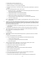
1
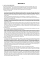
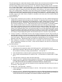
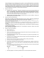
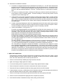
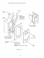
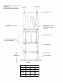
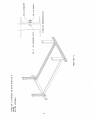
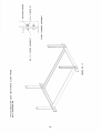
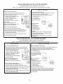
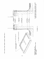
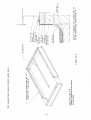
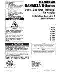
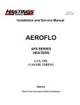
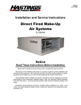
ISSB-1
July, 2007
Installation and Service Instructions
DIRECT FIRED, ELECTRIC, STEAM
AND HOT WATER
SB-112 through SB-240
NOTICE
Read These Instructions before installation
Project Name:________________________________________
Phone No.:__________________________________________
Location:____________________________________________
Installer:_____________________________________________
Phone No.:__________________________________________
Date Installed:________________________________________
FOR YOUR SAFETY
If you smell gas:
1. Open windows.
2. Don’t touch electrical switches
3. Extinguish any open flame.
4. Immediately call your gas supplier.
WARNING: Improper installation, adjustment, alteration, service or
maintenance an cause property damage, injury or death. Read the
installation, operating and maintenance instructions thoroughly before installing or servicing this equipment.
FOR YOUR SAFETY
The use and storage of gasoline or other flammable vapors and liquids in open containers in the vicinity of this appliance is hazardous.
ADDENDUM
NOTE: A low-temperature limit control is recommended in areas where freeze-up protection is needed
in the event of burner shutdown.
NOTE: Install heater such that the ignition system is not directly exposed to water spray, rain or dripping
water.
NOTE: If not supplied by the factory, provide an electric switch having adequate ampacity (see specification plate on heater for voltage and ampacity) and shall be installed in accordance with Article
430 of the National Electrical Code, ANSI/NFPA 70.
NOTE: Refer to markings on heater control box for locations for field installed wiring and control wiring.
NOTE: Refer to heater rating plate for determining the minimum gas supply pres sure for obtaining the
maximum gas capacity for which this heater is specified.
TABLE OF CONTENTS
SECTION 1 – General Information
A
– Installation and Service Instructions……………………………………………………………………... 2
B
– Notice to Equipment Users…………………………………………………...…………………………... 2
C
– Equipment Servicing and Shipping.,……………………………………………………………………..
2
D
– Specifications……………………………………………………………………………………………….
3
SECTION 2 – Installation
E
– Installation Procedures…..………………………………………………………………………………..
4
F
– Pre-Start Inspection………………………………………………………………………………………..
7
G
– Start-Up……………………………………………………………………………………………………... 8
H
– Sequence of Operation……………………………………………………………………………………. 10
I
– Miscellaneous Maintenance……………………………………………………………………………..
11
J
– Installation of Roof Curbs………………………………………………………………………………..
11
SECTION 3 – Trouble Shooting
K
– Trouble Shooting the Gas Unit……………………………………………..……………………………. 12
L
– Trouble Shooting the Electric Unit……………………………………………………………………….. 13
M
– Trouble Shooting the Steam or Hot Water Unit………………………………………………………… 14
SECTION 4 – Illustrations
Unit Assembly – Figure 1…………………………………………………………………………………………… 16
Unit Assembly – Figure 2…………………………………………………………………………………………... 17
Unit Suspension – Figure 3………………………………………………………………………………………… 18
Unit Suspension – Figure 4………………………………………………………………………………………… 19
Unit Assembly and Suspension – Figure 5……………………………………………………………………….. 20
Unit Assembly and Suspension – Figure 6……………………………………………………………………….. 21
Duct Connections – Figure 7……………………………………………………………………………………….. 22
Intake Hood – Figure 8……………………………………………………………………………………………… 23
Remote Control Panel – Figure 9………………………………………………………………………………….. 24
Remote Control Panel Installation – Figure 10…..………………………………………………………………. 25
Vertical Unit – Figure 11……………………………………………………………………………………………. 26
Vertical Unit Base Frame – Figure 12…………………………………………………………………………….. 27
Vertical Unit Base Frame – Figure 13…………………………………………………………………………….. 28
Valve Adjustments ………………………………………………………………………………………………….. 29
Roof Curbs – Figure 14……………………………………………………………………………………………... 30
Roof Curbs – Figure 15……………………………………………………………………………………………... 31
- 1-
SECTION 1 – General Information
A. INSTALLATION AND SERVICE INSTRUCTIONS
Installation and service manuals are made up for each individual order. The purpose of the following
instruction is to present a guide for proper installation and operation of said equipment and to act as
a supplement to the services of a qualified field service engineer at initial start-up of a Hastings piece
of equipment. We recommend that this manual be readily available to operating personnel for reference as an aid for trouble diagnosis and proper maintenance.
Information for installation of the heater (1) in airplane hangars in accordance with the Standard for
Aircraft Hangers, ANSI/NFPA 409, and (2) public garages in accordance with the standard for Parking Structures, ANSI/NFPA 88A, or the Standard for Repair Garages, ANSI/NFPA 88B, and with
CAN/CGA B149 Installation Codes.
The installation shall conform with local codes, or in the absence of local codes, in accordance with
the National Fuel Gas Code, ANSI Z223.1, or the CAN/CGA B149 Installation Codes.
Instructions requiring that if the failure or malfunction of this heater creates a hazard to other fuel
burning equipment in the building, (e.g. when the heater is providing the make-up air to a boiler
room), the unit is to be interlocked to open inlet air dampers or other such devices.
Authorities having jurisdiction should be consulted before installations are made. Local codes may
require additional safety controls and/or interlocks.
B. IMPORTANT NOTICE TO EQUIPMENT USERS
Models SBD-112 through SBD-218 are shipped with burner section and blower section assembled.
Intake hood and birdscreen, filter section, intake or discharge damper sections, or other large accessories are assembled, but shipped as individual items.
Models SBD-222 through SBD-240 are shipped as separate sections.
SBE, SBDR , SBS, SBW, and vertical units are shipped in the same manner as explained above.
All options and accessories are shipped mounted and wired whenever possible – within the limitations of shipping and handling. Any accessories which include wiring that are shipped separate (i.e.,
intake or discharge dampers) require no additional conduit or wiring in the field. All wire leads will be
tagged for reconnection in the field.
The SB unit is designed to simplify field installation. All parts have been designed in module form to
facilitate field installation of parts and accessories. The purpose of this manual is to supplement, but
not to replace the services of qualified field service personnel to supervise the initial start-up and
adjustment of the SB unit. Persons without previous experience with large commercial and industrial
make-up air equipment should not attempt the initial adjustment and check-out procedure essential
before such installations may be considered as ready for operation.
C. EQUIPMENT SERVICING AND SHIPPING INFORMATION
1.
Periodic Service
Periodic service on any piece of mechanical equipment is necessary for efficient operation. Hastings
has a nationwide service organization available to make quick and dependable servicing of make-up
air, return air, heating, ventilation, or air handling type equipment.
Representatives of this service organization are trained at the factory by qualified engineering and
service personnel. In addition, the company has trained service engineers who are always available
for consultation on any service problems in the field.
2.
Start-Up Service
This service includes the presence of a service engineer to perform the initial start-up and adjustment of the equipment, instruction of the owner’s maintenance personnel in proper operation and
maintenance, and return calls for any adjustments required to a particular unit within a period of
ninety (90) days after start-up is complete. Customer’s loss of power or fuel will not constitute need
for any return calls.
-2-
3. Factory Operations Test
All SB air handling, heating/ventilating, and make-up air units are given a complete operations test and control circuit check-out before final shipment. A copy of the flame test report and bill of material with testers
certifications stamp is included with each unit shipped.
4. Inspection of Shipment Upon Arrival
Shipments are made F.O.B. Hastings, Nebraska, by truck. The unit is securely strapped, tied, and
blocked to prevent shipping damage. All shipments are checked by an inspector before they are accepted
by the carrier. Parts that are shipped unmounted are noted on the bill of materials. These parts, where
feasible, are packaged and shipped with the units. Upon receipt of shipment, all units should be checked
against the bill of lading to insure all items have been received. The units should be checked carefully for
physical damage in the presence of the carrier’s representative. If parts are missing or damage has occurred, a claim should be filed immediately with the carrier. Widely varying conditions under which the units
are transported to the jobsite, unloaded, and installed make it impossible for Hastings to assume responsibility for handling of equipment in transit.
D. SPECIFICATIONS
1. General
Units are of the horizontal type with choice of HR-1, HR-2, and HR-3 blower discharge arrangements. Vertical units and units with a variety of blower discharge arrangements are available on request.
2. Cabinet
All cabinet parts are made from coated steels. All outside surfaces are primed and finish coated. Lifting
lugs are provided for ease in handling – see Figure No. 1 and Figure No. 2
3. Blower(s)
There are one or two centrifugal DWDI forward curved fan(s) (SB-240 provided with 2 backward incline
fans) with a one piece solid shaft or self-aligning prelubricated ball bearings on each unit. Blower wheel(s)
are statically and dynamically balanced. Adjustable drives are standard on all units through 10 HP. An
open drip-proof ball bearing squirrel cage induction T-frame motor is provided as standard for all voltages.
4. Gas Burner
The burner is a direct fired non-premix design with cast iron manifold and stainless steel mixing plates. A
spark ignited intermittent pilot for natural or propane gas at inlet pressure from 6 ounces through 1 pound is
standard. The burner is capable of a 22:1 turndown ratio. Maximum temperature rise is 119°F.
5. Gas and electric Controls
The following are furnished as standard components on all SBD gas fired units: NEMA 1 control box, remote control station with switches and indicating lights, electronic flame safeguard system with ignition
transformer, pilot controls, and electric safety shut-off valve, main gas hand shut-off valve, main and pilot
gas pressure regulators, motor starter, control transformer, high temperature limit switch, air flow switch,
automatic mild weather burner cut-out, and a modulating gas control system.
6 If the low-temperature control system is not an integral part of the heater, then it is recommended that a
low-temperature limit control be installed in areas where freeze-up protection is needed in the event of
burner shutdown.
7. Electric Heating
The following are furnished as standard components on all SBE electric heating units: the heating section
is UL listed with open type electric heating elements, control panel, circuit fuses, step controller and transformer with primary and secondary fusing, automatic reset thermal cut-out, heat limiter type secondary
safety protection, de-energizing contactors, and connecting block(s) for wiring of power supply. All fusing
per NEC and UL. Control transformer and disconnecting means are optional.
8. Steam or Hot Water Heating
The following is standard on all SBS and SBW units: coil section for indicated pressure or water temperature. Heating units shall have standard type coil. Heating/ventilating and make-up air units shall have
steam distributing type coil(s). Steam or hot water valves, linkage, and valve motors are shipped for field
mounting and wiring.
9. Control System
The standard control system permits the unit to operate for make-up air heating or heating and ventilating
purposes or run the blower(s) only for summer ventilation. Refer to the detailed sequence of operation included with this manual for exact unit operation.
-3-
SECTION 2
E. INSTALLATION PROCEDURE
The following recommendations are not intended to supplant any requirements of federal, state, or local
codes having jurisdiction. This equipment shall be installed and wired in accordance with regulations of
the National board of Fire Underwriters, National Electric Code, and local governing bodies. In Canada,
equipment should be installed in accordance with the applicable provincial regulations.
1. Handling the Equipment
The SB unit has been designed for rigging and handling through the units channel base frame and/or special
lifting lug hooks installed on the unit. All lifting operations must be accomplished with a load spreader of sufficient width to insure that the lifting cables clear the side of the unit. If this type of spreader is not available,
wood strips should be inserted between the cables and unit where necessary. See Figure No. 1 and No. 2
in this manual.
Units are suspended from same lifting lugs as used for handling. See Figure No. 3 and Figure No. 4
To be properly set, the SB unit should be placed on a solid flat and level foundation and set exactly as detailed later in the installation guide.
During the transit, unloading, and setting of the unit, bolts and nuts may have become loosened, particularly
in the pillow block ball bearing assemblies on blower section. It is recommended that all nuts and set screws
be tightened. Turn blower fan shaft by hand to make certain that no rubbing occurs and to check that bearing lock rings are tight.
Open the cover on the electrical control box located at the top on the side of the burner (blower section if air
handling unit only) section. Box can be opened by turning main fused disconnect switch to the “off” position
(disconnect is optional on air handling equipment). Inspect all wire terminals and wiring terminations to ensure connections are tight. If unit is supplied with an electric heating section, check the separate electrical
terminal box for any loose connections.
2. Locating the Unit
Prior to locating the unit, authorities having jurisdiction should be consulted before installations are made.
Approval permits should be checked against the unit received.
Locate the SB unit exactly level, making certain there is enough clearance for opening and removing access
doors. Special attention should be given to supply (if required) and discharge duct connections. Electrical
power and control hook-up points and steam or hot water supply and return lines (if required) should also be
noted. This information should be cross-checked with the position of support beams and stand pipes to insure that support structure dimensions coincide with those of the unit. Under structure beam spacing should
also be checked to preclude any interference with air ducts. Allow adequate clearance on both sides of unit
for access to bearings, motor, and all internal components. The heater inlet shall be located in accordance
with the applicable building code provisions for ventilation air.
3. Location of Accessories
The remote control panel will be located in the burner or electric section of the unit and must be removed
and installed by the electrical contractor. Remote control panels for air handling units will be located in the
blower section for shipment. See remote control panel details in this bulletin. Field constructed intake accessories should be properly designed to minimize the entry of snow and rain. Instructions that adequate building relief shall be provided so as to not over pressurize the building when the heating system is operating at
its rated capacity. It should be noted that this can be accomplished by taking into account, through standard
engineering methods, the structure’s designed infiltration rate; by providing properly sized relief openings; or
by interlocking a powered exhaust system; or by a combination of these methods.
4. Electrical Connections
All wiring must comply with all applicable local, state, provincial, and national electric codes.
Prior to running power to the unit, visually inspect all nameplates, control voltage wiring, control transformer,
and main fused disconnect switch on the unit – cross check with bill of material to insure that the voltage
option on the order is the voltage option received.
If optional motorized dampers are used, connect electrical wires supplied (in factory furnished conduit) with
unit to damper motor as shown on electrical wiring diagram. Adjust linkage so that damper will close when
blower switch in remote control panel is in ”off” position. If unit includes selectra modulation with discharge
temperature selector dial, the discharge temperature selector dial may be moved from shipping position inside master control panel on the unit to desired location. Run wires in separate conduit above is required.
Complete all wiring to any optional accessories as shown on unit bill of material and electrical wiring diagram
as required before applying voltage to the unit.
-4-
The total amperage of the main fused disconnect switch, blower motor, and control circuit transformer fusing
is affected by the addition of 25% to the full load amps as required by the National Electric Code.
Check the supply voltage before energizing the unit. The maximum voltage variations should not exceed ±
10%. Phase voltage unbalance must not exceed 2%. Use proper wire sizing practices when running wires
for the remote control panel. If the automatic gas ignition control system is exterior to the heater, a statement that the heater be installed such that the gas ignition control system is not directly exposed to water
spray, rain or dripping water. Identification of the entry location(s) for field-installed wiring and control wiring.
Adequate instructions shall be provided for field wiring of equipment,if applicable. Information that an electric disconnect switch having adequate ampacity (see marking on the heater for voltage and ampacity) if not
provided as part of the heater, shall be installed in accordance with Article 430 of the National Electrial
Code, ANSINFPA 70.
5. Piping Connections
a. All gas piping connections are not shown in this manual because of the many manifold arrangements
available due to approval codes and types of gas modulation. All gas piping must comply with “Standard
of National Board of Fire Underwriters” and all applicable local codes. Contact factory if exact gas piping
dimensions are required. Standard pipe caps are furnished on manifold for shipment from factory.
Run correctly sized gas line to unit. Install manual shut-off valve and regulator if not already installed.
Note: gas line pressure must be as shown on specification plate when unit is operating at full input.
Vent pressure regulator(s) and vent valve if included with unit to outside of building. With vent pipe outside, install a proper vent cap and/or screen to prevent entrance of foreign material and plugging. The
heater and its individual shutoff valve must be disconnected from the gas supply piping system during
any pressure testing of that system at test pressures in excess of 1/2 psi (3.5 kPa.) The heater must be
isolated from the gas supply piping system by closing its individual manual shutoff valve during any pressure testing of the gas supply piping system at test pressures equal to or less than 1/2 psi (3.5 kPa.).
b. If steam, hot water, or chilled water coils are used, all piping connections must be made according to
accepted trade practices or the general arrangement drawings furnished with the unit. Because of the
many variations of supply and drain connections required, it is not possible to include all piping connections in this manual. Piping must comply with “Standards of National Board of Fire Underwriters” and all
applicable local codes. Standard pipe caps are furnished on manifold for shipment from factory.
c. Pipe couplings for connection of condensate drains on applicable units are furnished. Standard pipe
caps are furnished for shipment from factory. A trap must be installed in the drain line to minimize the
loss of conditioned air.
6. Duct Connection(s)
a. Indoor Units – See Figures No. 3 and No. 4.
1.
Lifting lugs serve as suspension points on all indoor type units – see Figures No. 5 and 6.
2.
Make required opening in wall and line with an angle frame. Inside should be completed before outside is started to avoid any crumbing of penetrated wall. – see Figure No. 7.
3.
Insert insulated fresh air collar through the opening with flanges turned out to provide rigidity.
4.
Anchor intake hood with birdscreen to outside of wall – see dimensions for intake hoods on Figure
No. 8.
5.
Caulk perimeter of opening to make connection water tight.
6.
Units with a vertical – upblast discharge arrangement must have discharge ductwork supported from
building support members and not supported from the equipment. NO DISCHARGE DUCTWORK
IS TO BE SUPPORTED BY EQUIPMENT DISCHARGE OPENING CONNECTIONS.
NOTE: On indoor units, intake hood and birdscreen and any appropriate ductwork must be full size of
unit opening – see Figure No. 8.
b. Outdoor Units – See Figures No. 1 and No. 2
1.
Fasten intake hood and birdscreen directly to unit inlet. Caulk perimeter of opening to make connection watertight.
2.
Units with a vertical – upblast discharge arrangement must have discharge ductwork supported from
building support members and not supported from the equipment. NO DISCHARGE DUCTWORK IS
TO BE SUPPORTED BY EQUIPMENT DISCHARGE OPENING CONNECTIONS.
-5-
Connect discharge air duct or discharge grill to unit outlet. If unit is installed outdoors, be sure that duct
opening to building is adequately flashed and sealed to prevent leakage. All air to the heater must be
ducted directly from the outdoors. Recirculation of room air is not permitted. Adequate instructions shall
be provided to address heater installations where a duct work system is attached to the inlet of the
heater to purge the volume of the duct system with at least four air changes prior to an ignition attempt.
If in doubt regarding the application, consult the heater manufacturer.
7.
8.
Remote Control Panel
a.
Standard remote control panel: This panel is furnished with two heavy duty toggle switches and
three 115 volt signal lights. The switches control the blower (blower switch) and the burner (season
switch). The signal lights indicate supply blower operation (white light marked blower), burner operation (amber light marked heating), and safety lockout (red light marked lockout). See typical
remote control panel illustrated in Figure No. 9 in this manual.
b.
Optional remote control panel(s): Same as described above but with the addition of lights and
switches depending upon options ordered.
Remote Control Panel Specifications
Signal Lights: Pilot lights are rectangular neon type for 115 V.A.C. service. Lights are UL approved and
have 18 AWG 16/30 standard 105° C plastic wire leads. Bezel is chrome finished.
Switches: On-Off and On-Off-ON switch action with screw terminals. Rated at 15 AMPS at 115 V.A.C.
service with 3/4 HP rating at 115 V.A.C.
Lids and Cover: Remote control panel lids are 16 gauge brushed stainless steel. 1/8” high letters are
screen painted using Wornoy Duwell Enamel series 10-000 ink. Wiring box dimensions are 8” x 5” x 31/2” deep.
Terminal Blocks: Blocks are medium duty 15 AMP screw type. All terminals are numbered according to
corresponding wiring diagram.
Wiring: All wiring is 16 AWG 16/30 standard 105° C thermoplastic or equivalent. Wiring is color coded
per corresponding wiring diagram.
9.
Remote Control Panel Installation
a.
Refer to Figure No. 10.
b.
Align box with spirit level.
c.
If box is to be surface mounted, three (3) mounting holes in back of box are recommended. One in
each top corner and one at bottom center.
d.
If mounting holes are to be located in side of box as shown, four (4) holes are recommended. Two
at top and two at bottom.
e.
If wiring box is to be recessed, install so that open edge of box will be flush with finish wall. Install
optional flush mounting wall plate.
f.
Examine wiring box and control panel for clearance before providing conduit hole(s)
g.
All wiring must comply with applicable electric codes.
h.
Control panel is furnished with components wired to coded terminal strip. Installer to connect numbered terminal blocks on remote control panel to corresponding terminal block(s) in master control
panel on unit.
i.
The following table should be followed for proper low voltage wiring of remote control panel based
on a maximum voltage drop of two (2) volts.
Wire Size
Maximum Wire Length in Feet
16 ………………………………………………..160
14 ………………………………………………. 245
12 ………………………………………………. 395
j.
See Wiring diagram level referencing shielded cable for remote temperature dial connection.
-6-
10. Miscellaneous Installation Guidelines
a. All sections not shipped attached must be assembled in the field by 1/4 – 20 x 5/8” sheet metal screws
provided in the cloth bag with each ship along section. See previous instructions – Important Notice to
Equipment Users – or follow general arrangement drawing provided for this unit to determine which
items are crated and shipped separately. Figure No. 1 through Figure No. 4 show typical unit assemblies.
b. For outdoor or weather-proof models, a water-proof caulking is provided to seal all joints between optional sections as they are bolted together. Perimeter caulking on each ship along section must be
completed to insure a water tight unit.
C. If filter section is used, bolt to appropriate section by sheet metal screws provided. Provide caulking
as required. Filters and filter spacer(s) (if required) will be shipped installed in filter rack wherever possible. If filters are shipped separately, install filters and filter racks (see filter maintenance for details).
Filter spacer(s) will be banded to filter channel where shipping necessitates filters going separately
from filter section.
d. If intake or discharge dampers are used, bolt to appropriate section with sheet metal screws provided.
Provide caulking as required. Re-connect conduit and wiring to damper motor(s) as required. Electrical wires for damper motor(s) have been tagged for ease in connecting in the field.
e. Vertical Unit Installation – see Figure No. 11.
All sections not shipped attached must be assembled in the field with splice channels and 1/2” bolts
that are provided. Models SB-112 through SB-218 are shipped with burner section and blower section
assembled. Intake hood and birdscreen, filter section, intake or discharge damper sections, or other
large accessories are assembled, but shipped as individual items.
Models SB-222 through SB-240 are shipped as separate sections.
All sections are shipped in a horizontal position. SB-112 through SB-218 has top mounting channel
and base channel shipped assembled with blower/burner section. SB-222 through SB-240 has top
mounting channel shipped as one section, but not physically attached to either blower or burner section – see Figure No. 11.
Unit base assembly is shipped separately for field connection to mounting channels and anchoring to
floor. Optional filter and/or inlet damper section(s) mount in base assembly – see Figures No. 12 and
13. All 1/2” bolts and splice plates for unit assembly in the field are included with each unit.
The vertical SB unit is designed to simplify field installation. All parts have been designed in module
form to facilitate field installation of parts and accessories. The purpose of this manual is to supplement, but not to replace the services of qualified field personnel to supervise the initial start-up and
adjustment of vertical SB unit. Persons without previous experience with large commercial and industrial make-up air equipment should not attempt the initial adjustment and check-out procedure essential before such installations may be considered as ready for operation
F. PRE-START INSPECTION
This inspection is extremely important and should be completed with greatest care given to detail. A good
pre-start inspection will insure against possible unit damage on start-up and will save valuable analysis
time in the event malfunctions occur on start-up and check out.
1. Check to see that all factory installed pipe plugs have been removed.
2. Again, check supply voltage against unit voltage.
3. If an electric heating section is supplied, check supply voltage against element voltage.
4. Check all electrical connections in the main control panel and remote control panel.
5. Check that all fuses are installed and that fuse sizing agrees with the unit bill of material.
6. If optional steam, hot water, or chilled water coils are supplied, check to see that all piping connections are
secure and that face areas of coil(s) have not been damaged or blocked.
7. Check to see if all gas connections are tight and that all joints have been properly lubricated.
8. Check to see if all condensate drain piping has been completed (if required).
9.. Insure that all insulation is fastened securely to walls, ceiling, and floor areas.
-7-
10.
Check blower supply area to insure freedom of shaft rotation and proper belt tension.
11.
Check blower motor to insure that pulleys are secure and drive belts are tight
12.
Check filters for cleanliness, and in the case of throw-away; filters, make certain that they are free of
moisture. (Note: Wet filters will collapse under static pressure and the media will be sucked into the
downstream sections of the unit.)
13.
If any optional dampers are supplied, make certain that all dampers linkage is free to move and that no
binding will occur. If dampers are of the modulating type, check control capillary tubes to insure that the
tubes will not rub against any stationary objects.
14..
Check all areas for cleanliness.
15.
Secure all access doors.
16.
Check all canvas connectors (where used) between the unit and any duct work used.
17.
Instructions specifying that service personnel shall perform a gas leak check during heater start-up, to
verify the gas tightness of the heater’s components and piping under normal operating conditions.
18.
Adequate instructions shall be provided for adjusting the pilot flame.
19.
Adequate instructions shall be provided for checking the gas tightness of the safety shut-off valve(s).
G. START-UP
All safety and operating controls have been checked during the factory test period, however, it is advisable to
complete a similar check when first operating the unit.
1.
Remove any shipping blocks from (gas units only):
a. High limit switch (if mercury bulb type) mounted on burner cabinet. Remove limit switch cover, remove paper blocking, and tilt mercury bulb to reset.
b. Gas pressure switch(es) (if required) may have shipping screws. Remove screws if supplied.
c. Unit programming controller may be shipping with a paper shipping block. Remove programmer
cover and remove paper shipping block – re-install cover and adjust manual reset.
2.
Open pilot cock and purge air from gas line through plugged tee in pilot line, only if “Gas Pilot Ignition”
was provided.
3.
Check setting of inlet air controller. This is factory set at 65° F to shut down burner when outside temperature rises above 65° F. If unit is to be test run when outside temperature is above 65° F, this setting
will have to be raised for burner to operate. After unit has been test run, reset controller at 65° F.
4.
If 70° F discharge temperature is not desired, move appropriate discharge selector dial to new position
and set inlet air controller to a temperature at least 5° F below this setting. Note: No adjustment required on modulating gas valve. High and low fire positions are factory set for proper operation. In
some cases, it may be possible or desirable to reduce the low fire: be sure to keep continuous flame the
full length of burner.
5.
Close main disconnect switch.
6.
Standard units are operated from the toggle switches in the remote control panel. If it is necessary to
check blower motor rotation from the unit, jumper the respective electrical terminals at the unit as shown
on the electrical wiring diagrams.
Move blower switch to “on” position. White signal light marked “blower” should indicate that the blower is
operating. If blower runs but light does not come on, blower may be running in reverse direction. All
applicable safety controls are in series with blower motor starter coil and must be in the electrical circuit
for proper unit operation – see appropriate electrical wiring schematic.
7.
All three phase motors were properly phased during factory testing. If rotation is reversed, interrupt
main power supply and interchange any two of the incoming power leads .Re-establish power and recheck blower operation.
8,
On three phase unit, the starter contacts should pull in and hold quietly without “clatter” (relays serve as
starters on single phase units). If they do not operate quietly, check immediately for proper line voltage.
Even temporary low voltage at start-up will cause constant operating trouble and must be corrected before SB unit is placed in service.
-8-
9.
Re-check all set screws on motor sheave, blower sheave, and blower wheel(s). Check alignment of belts
and pulleys. Run blower for a few minutes and adjust motor take-up if necessary (see Figure No. 14). Do
not over-tighten belts since excessive tension will reduce belt life and cause excessive load on bearings.
After initial start has been made, give the belts a few days running time to become seated in pulley grooves
– re-adjust take-up bolt(s) as necessary. Run drive at full speed and adjust take-up until only a slight bow
appears in the slack side of the belts (see Figure No. 14). Do not roll belts over grooves or sheaves, as
this results in permanent belt damage.
10. Move season switch to “winter” position to light pilot – blower must be operating. Amber signal light marked
“heating” should indicate that the burner is operating. If pilot does not light, depress reset button on programming relay. If it becomes necessary to adjust pilot flame, check the micro ampere reading Adjust to obtain a micro ampere reading of 2. Make sure all gas cocks are open and gas pressure switch(es) (if required) are reset for burner operation.
11. Unit is factory pre-set to provide gas pressure as specified on unit spec/data plate mounted on unit for standard burner when firing at full input. Before making any regulator adjustments, be sure there is sufficient inlet
pressure.
12. Modulation System
a.
Unit with Selectra Modulation
1. Standard selectra system (Series 14)
a. MR212 valve high fire manifold adjustments
1. Disconnect wires from terminal #4 in the amplifier – see Figure No. 15 – this causes the
valve to call for continuous high fire.
2. Remove seal cap (A) and turn regulator pressure adjusting screw to obtain desired manifold
pressure. (Clockwise rotation increases pressure) - See Figure No. 17.
3. Reconnect the wires to terminal #4.
b. MR212 valve low fire or by-pass adjustment.
1. Disconnect wire from terminal #8 in the amplifier – see Figure No. 15. This causes the valve
to call for continuous low fire.
2. Remove seal cap (B) and loosen lock screw (C). Turn (D) to desired low fire adjustment.
(Clockwise rotation reduces minimum flow rate) - See Figure No. 17.
3. Tighten set screw (C), replace cap (B) and reconnect wire to terminal #8.
c.
MR611 valve high fire manifold adjustment.
1. Disconnect wires from terminal #4 in the amplifier – see figure No. 15. This causes the
valve to call for continuous high fire.
2. Adjust the pressure regulator to obtain the desired manifold pressure (7” WC. Max.).
3. Reconnect the wires to terminal #4.
d. MR611 valve low fire or by-pass adjustment.
1. Disconnect wire from terminal #8 in the amplifier – see figure No. 15. This causes the valve
to call for continuous high fire.
2. Remove cap (A) and turn adjusting screw (B) to desired low fire adjustment – see Figure No.
18.
3. Replace cap (A) and reconnect wire to terminal #8.
NOTE: If calibration of the amplifier or remote temperature selector is necessary, place an accurate
temperature measuring device as near the discharge air sensor as possible. Set the remote temperature at least 10° F above the outside air temperature.
1. If calibrating at the amplifier, adjust calibration potentiometer (A), Figure No. 15, until temperature reads the same as the set temperature. If the temperature is below the set point,
then rotate calibration potentiometer (A) clockwise. If the temperature is above the set point,
rotate the calibration potentiometer counter-clockwise.
-9-
2. If calibrating the remote temperature selector, rotate the calibration potentiometer (A), Figure No.
16, until the correct temperature is obtained. If the temperature is above the set point, the calibration potentiometer (A) should be turned counter-clockwise.
H. SEQUENCE OF OPERATION
1.
Typical sequence of operation – gas units: (see attached wiring schematic SBD-S2-AD - Figure No. 19)
Closing fused disconnect switch (FD) supplies 115 volt power to control circuit through 115 volt control transformer (T2). Unit is ready for operation.
Summer Operation
If three position season switch (SW ) is in the “summer” position and two position blower switch (BL) is “on“,
power is supplied to the two position fresh air/discharge air damper motor (DM). After approximately one
minute, the damper motor has reached its full open position, closing the damper proving switch (DP). Power
is supplied to blower motor starter (IM). Blower motor (MI) will run if blower motor overloads (OL’s) are not
tripped. Burner is inoperative. System white light (W) in remote control panel will be operational.
Winter Operation
If three position season switch is in the “winter” position, and if the high limit switch (HL) is operational,
blower starts as explained in summer operation above. If air flow is sensed by the air proving switch (AP)
and auxiliary starter contacts (IMI) are closed, power is supplied to burner protectorelay (PR).
If entering air temperature is below the setting of the entering air temperature controller (AT), protectorelay
powers ignition transformer (GN) and pilot valve (PV) opens. When pilot is lit, flame rod (FR) detects pilot
flame and ignition transformer drops out of electrical circuit. Main gas solenoid valve (MV) opens and pilot
lights main burner.
The alarm safety switch lockout terminals (AS) will close if detection of flame (or flame simulating conditions)
occur, if there is a failure to ignite or main flame, or on a loss of flame while burner is running. The alarm
lockout terminals will energize the safety lockout relay (2R) which will open the lockout relay contacts 2R1
and shut down the blower and burner. Safety lockout light (R) in remote control panel will be operational.
Burner flame is controlled by the modulating valve (MR) and discharge air controller (TD).
Flame is increased and decreased as discharge temperature rises and falls above and below setpoint of discharge air controller.
2.
Typical sequence of operation – electric units: (see attached wiring schematic EHV-ACD2T – Figure No. 20)
Closing optional main disconnect switch (FD) supplies 115 volt power to control circuit through 115 volt control
transformer (T2). Unit is ready for operation.
Summer Operation
If three position season switch (SW) is in the “summer” position and the three position blower switch (BL) is
in the “on” position, power is supplied to the blower motor starter (IM). Blower relay (6R) and blower delay
timer (DT) must be operational. Blower motor (MI) will run if blower motor overloads (OL’s) are not tripped.
Heater is inoperative. System white light (W) in remote control panel will be on if auxiliary blower motor
starter contacts (IMI) are closed. Optional clogged filter light (B) in remote control panel will be operational if
a blocked intake or clogged filter situation occurs.
Winter Operation
If three position season switch is in the “winter” position, heating control relay (7R) is operational, and air flow
through unit has been proven by blower air proving switch (AP), the electronic sequencer (SE) will modulate
for desired heat if power is supplied to sequencer through sequencer control transformer (T2) and automatic
reset thermal cutout (AR).
Heating is controlled by the modulating sequencer through the action of the over-riding modulating room
thermostat (MB). If the discharge temperature of the unit falls below the setting of the modulating discharge
air controller (MD), the over-riding room thermostat is over-ridden and heating output is increased until the
modulating discharge air controller is satisfied.
If the discharge temperature of the unit rises above the setting of the modulating high limit control (MC), the
over-riding room thermostat is over-ridden and heating output is decreased until the modulating high limit
control is satisfied.
The sequencer automatically recycles to the off position on any interruption of power.
System heating light (A) in remote control panel will be on when season switch is in the “winter” position.
- 10 -
I. MISCELLANEOUS MAINTENANCE
1.
Filters – check filters at least once each season and clean or replace as necessary.
Standard filters are of the heavy duty fiberglass mesh throw-away type. No attempt should be made to
clean and re-use these filters. Replacement filters should be an equivalent to the type supplied standardly
with the unit. See bill of material for size, type, and number required.
The optional cleanable filters are of the high velocity aluminum mesh type. These filters may be washed
with water, as the mesh is originally coated with a water soluble oil solution. The filters should be dried
and recoated with oil solution, such as “Evans Filter Fluid”. Replacements for damaged filters should be of
an equivalent type as originally supplied with the unit. See bill of material for size, type and number required. The oil coating solution is available from the filter manufacturer.
Filter racks as supplied with some sizes of SB units may have at least one filter spacer to eliminate the bypassing of unfiltered air. These spacers (if used) must be re-installed after the completion of any maintenance work.
2.
Blowers – check blower and related components at least twice yearly.
Blower motor has sealed bearings, thus eliminating the need for periodic oiling. Motor bearings vary with
size and type of application. Refer to motor instructions for proper maintenance schedule. Belts must be
tightened as explained previously if so required. Check pulleys for proper alignment
J. INSTALLATION OF ROOF CURBS
The SB unit can be supplied with an optional roof curb. The curb greatly facilitates installation thereby
reducing installation costs. All connections to the unit ductwork, piping, and electrical power and control
wiring can be made through the roof opening.
The curb may be shipped prior to unit shipment, or may accompany the SB unit to the jobsite. All SB
curbs are shipped knocked down from factory. The curb is 3 1/2” thick and includes a 2” high wood nailer
strip curb adaptor, and sealing tape. Curb is made from 18 gauge galvanized steel and painted. .Curb
does not include insulation or can’t strip (may be required to adapt to all types of roofing – including gypsum). See Figure No. 21 and Figure No. 22.
Use extreme caution in handling the curb. Proper handling and positioning will insure a water tight curb
unit installation.
Re-check approval prints prior to installation. Be sure that there are no obstructions to ducting and that
proper planning has been exercised in connection of piping and/or electrical services.
The curb assembly must be supported by roof trusses at intervals no greater than eight feet. It may; be
bolted or welded to either trusses or roof decking; however, connection to roof trusses is recommended.
The curb is designed to carry the weight of the unit. Additional support is required for certain applications.
Placement of the curb is critical in squareness and leveling. Shims for leveling must be applied to the curb;
application of shims to the unit will tend to destroy the sealing effect after installation. Make sure sealing
tape and adaptor strip are in place before unit is set. A bubble level must be used in the leveling process.
Squareness must be checked by measuring diagonals. Allowable tolerance is 1/4” difference between
diagonal measurements. Double check approval prints before setting of unit. Upon completion of setting
the curb, apply roofing material and flashing as required.
The unit manufacturer will not assume responsibility for leaks if the curb adaptor strip and sealing tape are
not used. Be careful not to allow gaps where two pieces of sealing tape meet. Unit is now ready for setting on the roof.
SBD-222, 227 233, and 240 require a field fabricated sheet metal skirt around base of unit. (Contact factory for details).
SECTION 3
K. TROUBLE SHOOTING THE GAS SB UNIT
1.
If Blower Fails to Operate, Check to See If:
a. Main disconnect switch or circuit breaker closed.
b. All main fuses (if disconnect switch used) are in line.
c. Control transformer is supplying 115 volts to control circuit.
- 11 -
d. Blower switch in remote control panel is “on”.
e. High limit control is in circuit (manual reset switch).
f.
Magnetic motor starter is in circuit (manual reset starter).
g. There are any loose wires or connections in blower circuit at either terminal block or control components.
Also check the following optional controls, if used, to see if:
a. Main gas cock is open – units equipped with manual reset low gas pressure switch must have
gas at switch for proper switch operation.
b. Low gas pressure switch in circuit (manual reset switch).
c.
High gas pressure switch in circuit (manual reset switch).
d. Damper motor end switch is closed (damper motor must be full open).
e. Low limit temperature control setting too high or n.c. over-riding timer contacts open.
f.
Access door switch(es) open.
NOTE: If other optional controls are supplied on special applications, check to see if they are in the
electrical circuit.
2.
If blower runs, but remote control panel blower light doesn’t come on, air proving switch is faulty, discharge is blocked, belt(s) loose and slipping, or blower is running backwards. Also check to see if air
proving switch sensing tube is plugged or has been crimped. Also check to see if RPM and CFM required match specification plate on unit.
a. If a pre-purge timer (separate from programming relay) is used, blower light won’t come on until
unit has purged.
b. Blower light in remote panel will not function until all air proving safety controls are operational
3.
Units equipped with filter sections will have a clogged filter or blocked intake light in remote control
panel. If filter light is on and blower light is off, check for:
a. Dirty filters.
b. Blocked intake.
4.
If blower starts and remote control panel blower light comes on, operates for a short time, and then
stops, check:
a. Starter reset and possible motor overloading.
b. To see if unit equipped with low outlet temperature shut-off with cold start time delay.
1. Low limit control setpoint too high.
2. Over-riding timer completing its cycle before burner operates.
3. Burner fails to operate.
5.
If blower operates and blower signal light is on, but burner fails to operate, check to see if:
a. Season switch in remote control panel is in “winter” position.
b. Auxiliary starter contact in magnetic motor starter closed.
c. Programming relay in safety lockout.
e. Intake air temperature controller set point above outdoor ambient temperature.
e. Ignition transformer functioning properly.
f.
Spark gap is approximately 3/8”.
g. Flame rod wire and spark ignition wire for loose connections and/or reversed wires.
h. Any electrode insulators are cracked – replace as required..
i.
Pilot gas valve is open and that pilot has been lit (purge pilot gas line to eliminate any air).
- 12 -
j.
A three to four micro-amp reading fof pilot is being attained.
k. Main gas valve(s) open.
6. If unit does not heat air, check to see if:
a. Modulating valve is functioning properly
b. All gas cocks are in full open position.
c. Inlet pressure to unit agrees with unit specification plate.
d. Gas pressure at burner is 4 1/2” W.C. If not, adjust main gas pressure regulators on unit until there is 4
1/2” W.C. at burner. (If unit is designed for reduced manifold pressure, correct pressure to agree with that
shown on unit specification plate),.
7. If burner ignites, but modulating valve fails to open, check to see if:
a. Temperature selector dial is set at proper temperature range.
b. Motor and controller are wired properly.
c. Setting of discharge temperature selector dial or modulating room thermostat.
8. If unit is equipped with motorized pre-mix burner and burner does not operate, check to see if:
a. Burner relay or starter coil energized.
b. Burner starter (if required) needs resetting.
c. Differential burner proving switch closing (blower must run for switch to close).
L. TROUBLE SHOOTING THE ELECTRIC SB UNIT
1. If blower fails to operate, check to see if:
a. Optional main disconnect switch or circuit breaker closed.
b. All main fuses (if disconnect switch used) are in line.
c. Control transformer is supplying 115 volts to control circuit.
d. Blower switch in remote control panel is “on” if unit used for make-up air, or in the “on” or “auto” position if
unit is being used for space heating or heating/ventilating.
NOTE: If blower switch is in “auto” position, blower will operate for approximately 90 seconds after
switch is turned off.
e. Blower start relay coil energized and contact closed.
f.
Fan delay timer heating element energized and contacts closed.
g. Magnetic motor starter is in circuit (manual reset starter).
h. There are any loose wires or connections in blower circuit at either terminal block or control components.
Also check the following optional controls, if used to see if:
a. Damper motor and end switch is closed (damper motor must be full open).
b. Low limit temperature control setting too high or n.c. over-riding timer contacts open.
c. Access door switch(es) open.
NOTE: If other optional controls are supplied on special applications, check to see if they are in the electrical circuit.
2. If blower runs, but remote control panel blower light doesn’t come on, auxiliary starter contact in magnetic
motor starter not closing.
3. Units equipped with filter sections will have a clogged filter or blocked intake light in remote control panel.
4. If blower operates, but electric heater fails to operate, check to see if:
a. Season switch in remote control panel is in “winter” position.
- 13 -
b. Air proving switch is closed – check to see if:
1. Discharge is blocked
2. Belt(s) are loose and slipping.
3. Blower is running backwards.
4. Sensing tube is blocked or crimped.
c. Heating relay coil is energized and contacts closed.
d. Standard modulating step controller has power – check to see if:
1. Step controller power transformer fuses are in electrical circuit.
2. Power transformer supplying 115 volts.
3. Automatic reset thermal cutout is closed.
e. Step controller is functioning.
f.
Any or all sub-circuiting heating element fuses in circuit.
g. Magnetic heating element contractor coils are energized and contacts are closed.
h. Thermally operated heat limiters are in power legs to heating elements.
5.
If unit does not heat air, check to see if:
a. Modulating step controller is operating through all heating steps.
b. Sub-circuit heating element fuses in circuit.
c. All magnetic heating element contactors are operational
d. Heat limiters are n.c. and in the electrical circuit.
NOTE: Electric heating SBE units may not be furnished with a disconnect switch or circuit breaker. If any
service work is to be required, opening more than one disconnect switch may be required to completely de-energize system. Make no attempt to re-wire any heating element circuits if a failure occurs. Contact home office.
M. TROUBLE SHOOTING THE STEAM OR HOT WATER SB UNIT
1.
If blower fails to operate, check to see if:
a. Main disconnect switch or circuit breaker closed.
b. All main fuses (if disconnect switch used) are in line.
c. Control transformer is supplying 115 volts to control circuits.
d. Season switch in remote control panel in “summer” position, or if in “winter” position that heating control relay coil is energized and contacts are closed.
e. Freezestat(s) are n.c. and in the electrical circuit.
f.
Freezestat control relay coil energized and contacts are closed.
Also check the following optional controls, if used, to see if:
a. Damper motor end switch is closed (damper motor must be full open).
2.
If blower runs, but remote control panel blower light doesn’t come on, air proving switch is faulty, discharge is blocked, belt(s) are loose and slipping, or blower is running backwards. Also check to see if air
proving sensing tube is plugged or has been crimped.
3.
If blower operates and blower signal light is on, but system fails to heat air to desired temperature, check
to see if:
a. Season switch in remote control panel is in ”winter” position.
b. Heating relay contacts are closed.
c. Two position or modulating valve (and controller if modulating system) is functioning properly.
- 14 -
d. All steam and hot water lines are open and free flowing.
e. Steam pressure, water temperature and flow rates are per specifications.
f.
On two coil systems that outside air temperature controller is functioning properly.
NOTE: We cannot guarantee coils against freezing, but the likelihood of freezing can be minimized if the
installer takes the following precautions:
1. Provide adequate sizing of condensate return lines, traps, and vents to provide for a speedy flow of condensaate from the coil
2. Do not bush or reduce return trapping size.
3. Do not drain steam mains or branch lines through coils. Steam lines should always be drained ahead of
control valves.
4. When more than one coil section is installed, a separate steam trap must be provided for each.
5. Use only bucket or float and thermostatic traps for condensate removal. Use thermostatic traps for venting only.
6. Steam traps should be sized for three (3) times the calculated condensate load at coil design conditions.
7. Traps should be selected for the pressure differential across the trap – not boiler pressure.
8. Strainers should be installed ahead of traps to prevent dirt and sludge from affecting operation.
9. Vacuum breakers should be provided. A 1/2” 15 degree swing check valve is recommended, installed as
close to the coil as possible. The vacuum breaker line can be vented to atmosphere or connected into the
return line on the distant side of the steam trap on low pressure systems. On steam systems at 15 PSIG
and above, air and non-condensable gases should be continuously vented from the return by a 1/4” petcock in a riser off the condensate return ahead of the trap. The petcock should be left open for continuous
venting. Vent air lines should not be returned to the condensate return main.
10. If condensate must be lifted above coil return level into overhead mains or if return mains are pressurized,,
a pump and receiver should be installed between condensate traps and return mains.
Most of the common causes of trouble have been covered and one of more remedies suggested to correct the
malfunction, but if SB unit still fails to operate properly, notify the nearest Hastings service representative.
- 15 -
- 16 -
INTAKE HOOD
AND
BIRDSCREEN
FILTER
SECTION
TYPICAL SB-112 THROUGH SB-218 UNIT ASSEMBLY
INCLUDING:
LIFTING LUGS
WEATHERPROOF CONSTRUCTION
LINE BURNER
FIGURE NO. 1
BURNER
SECTION
WEATHERPROOF
CONTROL
ENCLOSURE
BLOWER
SECTION
- 17 -
INTAKE HOOD
AND
BIRDSCREEN
FIGURE NO. 2
FILTER
SECTION
TYPICAL SB-222 THROUGH SB-240 UNIT ASSEMBLY
INCLUDING:
LIFTING LUGS
WEATHERPROOF CONSTRUCTION
LINE BURNER
WEATHERPROOF
CONTROL
ENCLOSURE
FIELD INSTALLED SPLICE CHANNELS REQUIRED TO ASSEMBLE SECTIONS
(SEE PAGE 7, SECTION 10 a.b.c. FOR ADDITIONAL DATA.)
BURNER
SECTION
BLOWER
SECTION
- 18 -
BURNER
SECTION
FIBURE NO. 3
FILTER
SECTION
TYPICAL SB-112 THROUGH SB-218 INDOOR SUSPENDED
UNIT INCLUDING:
SERVICE PLATFORM
LIFTING LUGS AND SUSPENSION POINTS
NOTE:
SERVICE PLATFORM SUSPENSION POINTS WILL VARY
WITH MANIFOLD AND CONTROL OPTIONS
BLOWER
SECTION
- 19 -
BURNER
SECTION
FIGURE NO. 4
FILTER
SECTION
TYPICAL SB-222 THROUGH SB-240 INDOOR SUSPENDED UNIT
INCLUDING:
SERVICE PLATFORM
LIFTING LUGS AND SUSPENSION POINTS
NOTE:
SERVICE PLATFORM SUSPENSION POINTS WILL VARY
WITH MANIFOLD AND CONTROL OPTIONS.
SUSPENSION RODS NOT FURNISHED BY UNIT
MANUFACTURER.
BLOWER
SECTION
- 20 FILTER
SECTION
TYPICAL SB-112 THROUGH SB-218 UNIT ASSEMBLY
INCLUDING:
LIFTING LUGS AND SUSPENSION POINTS.
FIGURE NO. 5
BURNER
SECTION
BLOWER
SECTION
NOTE:
SUSPENSION POINTS WILL VARY WITH MANIFOLD
AND CONTROL OPTIONS.
SUSPENSION RODS NOT FURNISHED BY UNIT
MANUFACTURER.
- 21 -
FILTER
SECTION
TYPICAL SB-222 THROUGH SB-240 UNIT ASSEMBLY
INCLUDING:
LIFTING LUGS AND SUSPENSION POINTS
FIGURE NO. 6
BURNER
SECTION
BLOWER
SECTION
NOTE:
SUSPENSION POINTS WILL VARY WITH MANIFOLD
AND CONTROL OPTIONS.
SUSPENSION RODS NOT FURNISHED BY UNIT
MANUFACTURER.
TYPICAL DUCT CONNECTION - INDOOR UNITS
Wall
Anchor
To Wall
Angle Frame
Birdscreen
Fresh Air
Duct
to unit intake
Duct Liner
Fresh Air Duct
FIGURE NO. 7
- 22 -
INTAKE HOOD AND BIRDSCREEN
Air Flow
TABLE OF DIMENSIONS (IN INCHES)
MODEL
A
B
SB-112
35
35 19/32
SB-115
40
43 5/16
35
SB-215
75 1/8
43 5/16
35
SB-218
79 1/8
46 7/8
39
SB-222
96 5/8
55 15/16
49
SB-227
114 3/8
59
58
SB-233
141
58 7/16
67
SB-240
150
66
80
FIGURE NO. 8
- 23 -
C
26 1/2
5
B
L
O
W
E
R
L
O
C
K
O
U
T
H
E
A
T
I
N
G
F
I
L
T
E
R
S
8
ON
SUMMER
OFF
OFF
WINTER
BLOWER
SEASON
FIGURE NO. 9
TYPICAL REMOTE CONTROL PANEL
REMOTE CONTROL PANEL DEPTH 3 1/2"
LID IS 16 GAGE BRUSHED STAINLESS STEEL
ALL LETTERS ARE SILKSCREENED BLACK
NOTE:
FILTER LIGHT MAY NOT BE REQUIRED ON ALL APPLICATIONS.
- 24 -
TYPICAL REMOTE CONTROL PANEL INSTALLATION
Wall
Stud or
Support
Installer to
provide mounting
holes & conduit
hole(s) as field
conditions require.
Wiring
Box
Typical installation
in Web of Bldg. Col.
Conduit or Flex
(not by unit manufacturer)
to main control panel.
Cut in wall for
Wiring Box.
Control Panel
Wall Plate. Use
only when Wiring
Box is to be recess
mounted.
Wall Plate optional - Supplied on Request.
FIGURE NO. 10
- 25 -
TYPICAL VERTICAL UNIT INSTALLATION
INCLUDING:
WEATHERPROOF CONSTRUCTION
SB-222 THROUGH SB-240 SHOWN
BLOWER SECTION
TOP MOUNTING CHANNEL
(112-240)
BASE CHANNEL FRAME
(222-240) OR
MOUNTING CHANNELS
(112-218)
BURNER SECTION
SPLICE PLATES PROVIDED
FOR FIELD ASSEMBLY
FILTER SECTION
BIRDSCREEN
20" (MIN.)
42" (MIN. 240)
BASE ASSEMBLY
FIGURE 11
UNIT SIZE
DIMENSIONS (IN INCHES)
A
B
C
112-218
4
4
4
222-233
6
5 1/8
5 1/8
240
6
6
- 26 -
6
- 27 -
TYPICAL SB-112 THROUGH SB-218 VERTICAL UNIT
FRAME
BOLTING ASSEMBLY
FIGURE NO. 12
5/8 - 11 HEX NUT
TYPICAL CORNER ASSEMBLY
5/8 - 11 1-1/2 HEX HEAD BOLT
5/8 LOCKWASHER
- 28 -
FIGURE NO. 13
TYPICAL SB-222 THROUGH SB-240 VERTICAL UNIT FRAME
BOLTING ASSEMBLY
5/8 - 11 HEX NUT
TYPICAL CORNER ASSEMBLY
5/8 - 11 1-1/2 HEX HEAD BOLT
5/8 LOCKWASHER
Valve Adjustments For A1014 Amplifier
(See bulletin MT2035 for additional M/MR valve information)
NOTE: Low fire adjustment should be checked whenever the high fire adjustment is changed.
MR 212 Valve
M411, 511, 611 VALVE
High Fire Manifold Adjustments:
1. Disconnect wires from amplifier terminal #4. This
causes the valve to call for continuous high fire.
2. Remove seal cal (a), and turn
regulator pressure adjusting screw
to obtain desired mainfold
pressure. (Clockwise rotation
increases pressure.)
3. Reconnect hte wires to amplifier
terminal #4.
NOTE: If low fire bypass is on
maximum, the desired high fire outlet
pressure may not be achieved.
High Fire Manifold Adjustments:
1. Disconnect wires from amplifier terminal #4, this causes
the valve to call for continuous high fire.
2. Adjust the pressure regulator to obtain the desired
manifold pressure (7"
w.c. maximum).
3. Reconnect the wires
to amplifier terminal
#4.
B
Low Fire ro Bypass
Adjustments:
1. Disconnect wire
from amplifier
terminal #8, this
A
causes the valve to
call for continuous
low fire.
2. Remove cap (A), and turn adjusting screw (B) to
desired low fire adjustment. (Clockwise rotation
reduces minimum flow rate.)
3. Replace cap (A), and reconnect wire to amplifier
terminal #8.
Low Fire or Bypass Adjustments:
1. Disconnect wire from amplifier terminal
#8, this causes valve to call for continuous low fire.
2. Remove cap (B), and loosen lock screw (C). Turn (D)
to desired low fire adjustment. (Clockwise rotation
reduces minimum flow rate.)
3. Tighten set screw (C), replace cap (B) and reconnect
wire to amplifier termnial #8.
Valve Adjustments For A1044 Amplifier
(See bulletin MT2035 for additional M/MR valve information)
NOTE: Low fire adjustment should be checked whenever the high fire adjustment is changed.
MR 212 VALVE
M411, 511, 611 VALVE
High Fire Manifold Adjustments:
1. Disconnect wires from amplifier terminal #2 & #4.
This causes the valve to go to continuous high fire.
2. Remove seal cap (a), and turn
MODULATOR
regulator pressure adjusting
screw to obtain desired manifold
pressure. (Clockwise rotation
increases pressure.)
3. Reconnect the wires to amplifier
terminal #2 & #4.
NOTE: If low fire bypass is on
maximum, the desired high fire
outlet pressure may not be achieved
Low Fire or Bypass Adjustments:
1. Disconnect wire from amplifier terminal
#8, this causes valve to go to continuous low fire.
2. Remove cap (B), and loosen lock screw (C). Turn (D)
to desired low fire adjustment. (Clockwise rotation
reduces minimum flow rate.)
3. Tighten set screw (C), replace cap (B) and reconnect
wire to amplifier terminal #8.
- 29 -
High Fire Manifold Adjustments:
1. Disconnect wires from amplifier terminal #2 and 34, this
causes the valve to go to continuous high fire.
2. Adjust the pressure regulator to obtain the desired
manifold presure
(7" w.c. maximum).
3. Reconnect the wires
to amplifier terminal
#2 & #4.
B
Low Fire or Bypass
Adjustments:
1. Disconnect wire from
amplifier terminal
A
#8, this causes the
valve to go to
continuous low fire.
2. Remove cap (A), and turn
adjusting screw (B) to desired low fire adjustment.
(Clockwise rotation reduces minimum flow rate.)
3. Replace cap (A), and reconnect wire to amplifier
terminal #8.
- 30 -
CONSTRUCTION NOTE:
CURB TO BE ASSEMBLED IN FIELD
BY INSTALLER
CROSSMEMBER (IF REQUIRED)
GASKET TO BE INSTALLED ON ENTIRE PERIMETER
OF CURB ASSEMBLY
TYPICAL SB-112 THROUGH SB-218 ROOF CURB DETAILS
FIGURE NO. 14
*GASKET FURNISHED BY HASTINGS IF ROOF
CURB IS PURCHASED FROM HASTINGS.
CANT STRIP
(NOT FURNISHED)
ROOFING FELT
(NOT FURNISHED)
RIGID INSULATION
(NOT FURNISHED)
CURB ADAPTER
(FURNISHED)
WOOD NAILER
(FURNISHED)
GASKET*
(FURNISHED)
- 31 -
CONSTRUCTION NOTE:
CURB TO BE ASSEMBLED IN FIELD
BY INSTALLER
GASKET TO BE INSTALLED ON ENTIRE
PERIMETER OF CURB ASSEMBLY
TYPICAL SB-222 THROUGH SB-233 ROOF CURB DETAILS
FIGURE NO. 15
WOOD NAILER
(FURNISHED)
GASKET*
(FURNISHED)
LAG BOLT
(NOT FURNISHED)
PRE-DRILLED HOLES
(FURNISHED)
UNIT BASE FRAME
CANT STRIP
(NOT FURNISHED)
*GASKET FURNISHED BY HASTINGS IF ROOF
CURB IS PURCHASED FROM HASTINGS.
ROOFING FELT
(NOT FURNISHED)
FLASHING
(NOT FURNISHED)
RIGID INSULATION
(NOT FURNISHED)
CROSSMEMBER
P.O. Box 669 · Hastings, Nebraska 68902-0669
Phone (402) 463-9821 · Fax (402) 462-8006
www.hastingshvac.com
E-mail: [email protected]