1
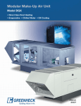
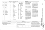
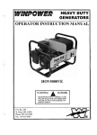
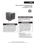
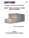
Part # 455305
READ AND SAVE THESE INSTRUCTIONS
Hooded Propeller Roof Fans
Belt Drive and Direct Drive
GREENHECK
®
P.O. BOX 410 SCHOFIELD, WISCONSIN 54476-0410
PH. 715-359-6171
Installation, Operating and Maintenance Manual
Upon receiving the unit, check for any damage and report it immediately to the shipper. Also assure all accessory
items are accounted for.
To minimize installation time, most fans are shipped completely assembled. Due to shipping size limitations, hoods for larger
fans will be shipped in sections. For these fans the hood and fan components can be transported to the roof location
separately. Hood assembly should begin after the fan is attached to the roof curb. Hood assembly instructions are included
with the hood components.
Care must be taken not to bend or distort the fan panel or drive components during installation.
All dimensions given in inches
Exhaust / Supply (Direct Drive Sizes 18-54 - Belt Drive Sizes 20-72)
W
C
B
TB
D
TD
Tall Base Option
2 1/2"
A sq.
Fan
Size
A
Base
Sq.
C
18
20
24
30
36
42
48
54
60
72
281/4
30 1/4
341/4
401/4
461/4
521/4
581/4
641/4
701/4
82 1/2
13
16
18
20
22
24
24
261/2
261/2
29
Filtered Supply
Standard
Base
B
23
27
29
34
391/2
421/2
431/2
49
50
53
D
10
11
11
14
171/2
181/2
191/2
221/2
231/2
24
Tall
Base
TB
401/4
441/4
461/4
511/4
563/4
593/4
603/4
661/4
671/4
701/4
WxL
TD
271/4 48 x 51
281/4 54 x 51
281/4 66 x 63
311/4 75 x 75
343/4 88 x 87
353/4 86 x 99
363/4 93 x 111
393/4 112 x 111
403/4 124 x 123
411/4 136 x 135
Damper Roof
Size
Opg.
Sq.
Sq.
18
20
24
30
36
42
48
54
60
72
20 1/2
22 1/2
26 1/2
32 1/2
38 1/2
44 1/2
50 1/2
56 1/2
62 1/2
74 1/2
(Belt Drive Sizes Only 20 - 72)
L
Tall Base Option
A sq.
Fan
Size
A
Base
Sq.
C
20
24
30
36
42
48
54
60
72
30 1/4
341/4
401/4
461/4
521/4
581/4
641/4
701/4
82 1/2
16
18
20
22
24
24
26 1/2
26 1/2
29
Standard
Base
B
27
29
34
391/2
421/2
431/2
49
50
53
D
11
11
14
171/2
181/2
191/2
221/2
231/2
24
Tall
Base
TB
441/4
461/4
511/4
563/4
593/4
603/4
661/4
671/4
701/4
TD
281/4
281/4
311/4
343/4
353/4
363/4
393/4
403/4
411/4
WxL
54 x 51
66 x 63
78 x 87
94 x 87
93 x 99
112 x 111
124 x 123
136 x 135
136 x 147
Damper Roof
Size
Opg.
Sq.
Sq.
20
24
30
36
42
48
54
60
72
Access to the motor compartment
On fan sizes 18 to 48:
- Remove two fasteners shown in fig. 1.
Carefully swing the hood 180 degrees and let it rest on
the roof. If desired, the entire hood may be removed
by removing the two additional fasteners on the
opposite side of the fan.
Use caution when handling the hood in strong winds.
On fan sizes 36 to 60 access to the motor compartment can
also be made by either:
- Removing birdscreen or filters and standing
under the hood of large fans.
- Removing one interlocking hood end section of
smaller units
Fig. 1
Fasteners
22 1/2
26 1/2
32 1/2
38 1/2
44 1/2
50 1/2
56 1/2
62 1/2
74 1/2
ELECTRICAL CONNECTIONS
Before electrical connections are made, the supply voltage, phase and ampere capacity must be checked for
compatibility with the fan motor. In addition, the supply wiring must be properly fused and conform to local and national
electrical codes.
If the electrical supply is to be routed to the fan from the interior of the building, it should pass through the conduit hole in
the fan panel. The supply wires are then connected to an optional safety disconnect switch (if supplied) or wired directly
to the motor.
PRESTARTING CHECKS
Check all fasteners and set screws for tightness. This is especially important for
bearing set screws.
The propeller should rotate freely and not rub on the fan panel venturi. Rotation
direction of the propeller should be checked by momentarily turning the unit on.
Rotation should be in the same direction as the rotation decal affixed to the unit
or as shown in Fig. 2. For 3-phase installations, fan rotation can be reversed by
simply interchanging any two of the three electrical leads. For single phase
installations follow the wiring diagram located on the motor.
Airflow
Airflow
Rotation
Rotation
FOR BELT DRIVE FANS
The adjustable motor pulley is preset at the factory for the specified fan RPM. Fan
speed can be increased by closing or decreased by opening the adjustable pulley.
Two or three groove variable pitch pulleys must be adjusted an equal number of turns
open. Any increase in fan speed represents a substantial increase in horsepower
required from the motor. Always check motor load amperage and compare to name
plate rating when changing fan speed.
Fig. 2
ROUTINE MAINTENANCE
WARNING
DISCONNECT AND SECURE TO THE "OFF" POSITION ALL ELECTRICAL POWER TO THE FAN
PRIOR TO INSPECTION OR SERVICING. FAILURE TO COMPLY WITH THIS SAFETY PRECAUTION
COULD RESULT IN SERIOUS INJURY OR DEATH.
Once the fan has been put into operation, a periodic maintenance program should be set up to preserve the reliability
and performance of the fan. Items to be included in this program are:
•
•
•
•
•
•
BELTS
BEARINGS
FASTENERS
SET SCREWS
LUBRICATION
REMOVAL OF DUST/DIRT
BELTS
Deflection =
Belt Span
64
Belt Span
Fig. 3
Premature belt failures are frequently caused by improper belt tension
(either too tight or too loose) or misaligned pulleys. The proper tension for
operating a V-belt is the lowest tension at which the belts will not slip at
peak load conditions. For initial tensioning, the proper belt deflection half
way between pulley centers is 1/64" for each inch of belt span. For
example, if the belt span is 64 inches, the belt deflection should be one
inch using moderate thumb pressure at midpoint of the drive (Fig. 3).
Check belt tension two times during the first 24 hours of operation and
periodically thereafter. To adjust belt tension, simply loosen four fasteners
(two on each side of the motor plate) and slide the motor plate away from
the fan shaft until proper belt tension is attained. On some fans, fasteners
attaching the motor to the motor plate must be loosened in order to
adjust the belt.
It is very important that the drive pulleys remain in proper alignment after
adjustments are made. Misalignment of pulleys will result in premature
belt wear, noise, vibration and power loss. See Fig. 4 .
WRONG
WRONG
WRONG
CORRECT
Fig. 4
BEARINGS (For belt drive fans only)
Bearings are the most critical moving part of the fan and should be inspected at periodic intervals. Locking collars
and set screws, in addition to fasteners attaching the bearings to the bearing plate, must be checked for tightness. In a
clean environment and temperatures above 32°F./below 200° F., fan shaft bearings with grease fittings
should be lubricated semi-annually using a high quality lithium based grease. If unusual environmental conditions exist
temperatures below 32°F./above 200°F., moisture or contaminants, more frequent lubrication is required.
With the unit running, add grease very slowly with a manual grease gun until a slight bead of grease forms at
the seal. Be careful not to unseat the seal by over lubricating or using excessive pressure. Bearings without grease fittings are
lubricated for life.
FASTENERS AND SET SCREWS
Any fan vibration has a tendency to loosen mechanical fasteners. A periodic inspection should include checking all
fasteners and set screws for tightness. Particular attention should be paid to set screws attaching the propeller to the
shaft and the shaft to the bearings. Loose bearing set screws will lead to premature failure of the fan shaft.
LUBRICATION
Refer to the paragraph on bearings for bearing lubrication. Many fractional horsepower motors installed on the smaller fans are
lubricated for life and require no further attention. Motors equipped with oil holes should be oiled in accordance with the
manufacturer's instructions printed on the motor. Use a high grade SAE 20 machine oil and use caution not to over lubricate.
Motors supplied with grease fittings should be greased according to directions printed on the motor.
REMOVAL OF DUST AND DIRT
Dirt clogs cooling openings on the motor housing, contaminates bearing lubricant and collects on propeller blades
causing severe imbalance if left unchecked. The exterior surface of the motor, fan panel and entire propeller should be
thoroughly cleaned periodically. Use caution and do not allow water or solvents to enter the motor or bearings. Under no
circumstances should motors or bearings be sprayed with steam or water.
DAMPER INSPECTION AND SERVICE
If an optional tall base with damper is supplied, access to the optional dampers and actuators is provided by a removable door.
Simply release the two cam latches and slide the damper out for inspection, cleaning or service.
For fan sizes 24 through 36 supplied without a tall base, the entire unit must be lifted off the roof curb for access to the damper.
For fan sizes 42 through 72 suppled without a tall base, access to the damper is made by removing one end birdscreen or filter
and working on the damper from above. SEE WARNING ON PAGE 2.
FILTER MAINTENANCE (FILTERED SUPPLY FANS)
Aluminum mesh filters should be cleaned on a regular basis
for optimum fan efficiency. The frequency of cleaning
depends upon the cleanliness of the incoming air.
To remove filters on fan sizes 24 to 30, first remove the hood
as shown in fig.1. The filters can then be pulled from the
slide-out racks (shown in photo). On fan sizes 36 to 60,
access panels on the end panels are provided which allow
the filters to be removed without removing the hood.
Filters should be washed with a mild detergent in warm
water. After the filters are dry, an adhesive spray available at
most filter distributors may be applied to increase filter
efficiency.
Sliding filter out of filter rack.
TROUBLESHOOTING
PROBLEM
CAUSE
Reduced airflow
Excessive Noise
CORRECTIVE ACTION
System resistance is too high.
Check backdraft dampers for proper operation.
Remove obstructions in ductwork. Clean dirty
filters. Check for adequate supply air for
exhaust fans or exhaust air for supply fans.
Fan too close to damper.
Increase distance between fan and damper.
Unit running backwards.
See pre-starting checks.
Fan speed too low.
Increase fan speed.
Excessive dirt on propeller.
Clean propeller.
Bearings
Tighten bearing collars and set screws
Lubricate bearings. Replace defective bearings.
V-Belt drive
Tighten pulleys on motor and fan shaft. Adjust
belt tension. Align pulleys. Replace worn belts
or pulleys. See "Routine Maintenance".
Excessive vibration
Remove dirt build-up from propeller. Check all set
screws and fasteners for tightness. Check for
worn bearing. Correct propeller imbalance.
Check for loose dampers, guards or ductwork.
Defective Motor
Replace motor.
Motor load amperage must be checked and compared to nameplate rating to avoid serious damage to motor when speed is increased.
Belt Drive Fans Parts List
10
Direct Drive Fans Parts List
6
4
7
5
9
4
3
8
3
5
2
2
1
1
1.
2.
3.
4.
5.
6.
7.
8.
9.
10.
11.
Fan Panel
Propeller
Drive Frame Channel (2)
Motor Plate
Motor
Motor Pulley
Shaft Pulley
Fan Shaft
Bearings (2)
Belt
Bearing Plate (Level 3 fans only - not shown)
1.
2.
3.
4.
5.
Fan Panel
Propeller
Drive Frame Channel (2)
Motor Plate
Motor
IOM RB 10-95