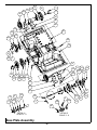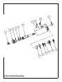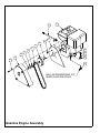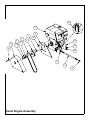
1
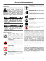
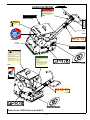
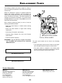
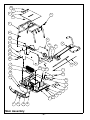
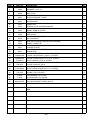
OPERATOR’S SAFETY
AND SERVICE MANUAL
GPR78
This manual covers the following serial numbers
and higher for each model listed:
GPR78...........................................7800110
VIBRATORY PLATES
MBW, Inc.
MBW (UK) Ltd.
250 Hartford Rd • PO Box 440
Slinger, WI 53086-0440
Phone: (262) 644-5234
Fax: (262) 644-5169
Email: [email protected]
Website: www.mbw.com
Units 2&3 CochraneStreet
Phone:+33 (0) 3 44 07 15 96
Bolton BL3 6BN
England, UK
Phone: 44 (0) 01204 387784
Fax: 44 (0) 01204 387797
E-mail: [email protected]
MBW FRANCE S.A.R.L.
L19604 / 07.15.E
©MBW, Inc. 2015
Printed in the USA
TABLE OF CONTENTS
Safety Information . . . . . . . . . . . . . . . . . . . . . . 1
Torque Chart . . . . . . . . . . . . . . . . . . . . . . . . . . . . . . . 9
Introduction . . . . . . . . . . . . . . . . . . . . . . . . . . . . . . . . . 1
Service Tools . . . . . . . . . . . . . . . . . . . . . . . . . . . . . . . 9
Safety Precautions . . . . . . . . . . . . . . . . . . . . . . . . . . . 1
Main Disassembly Procedure (Diesel Engine) . . . . . . 9
Safety Decals . . . . . . . . . . . . . . . . . . . . . . . . . . . . . . . 1
Main Disassembly Procedure (Gasoline Engine) . . . 10
Safety Decals: GPR78H (Decal Set #16031) . . . . . . . 3
Exciter Oil Change Procedure . . . . . . . . . . . . . . . . . 10
Lower Hydraulic Seal Replacement . . . . . . . . . . . . . 10
Specifications. . . . . . . . . . . . . . . . . . . . . . . . . . 4
Operation . . . . . . . . . . . . . . . . . . . . . . . . . . . . . 5
Bleeding And Adjustment of Hydraulic Controls. . . . 11
Base plate Disassembly Procedure . . . . . . . . . . . . . 12
Handle Disassembly Procedure . . . . . . . . . . . . . . . . 13
Introduction . . . . . . . . . . . . . . . . . . . . . . . . . . . . . . . . . 5
Control Head Disassembly Procedure . . . . . . . . . . . 13
Before Starting & Operating . . . . . . . . . . . . . . . . . . . . 5
Base plate Assembly Procedure . . . . . . . . . . . . . . . 14
Engine. . . . . . . . . . . . . . . . . . . . . . . . . . . . . . . . . . . . . 5
Control Head Assembly Procedure . . . . . . . . . . . . . 16
Starting Gasoline Engine . . . . . . . . . . . . . . . . . . . . . . 5
Handle Assembly Procedure . . . . . . . . . . . . . . . . . . 17
Starting Diesel Engine . . . . . . . . . . . . . . . . . . . . . . . . 5
Final Assembly . . . . . . . . . . . . . . . . . . . . . . . . . . . . . 17
Operating . . . . . . . . . . . . . . . . . . . . . . . . . . . . . . . . . . 5
Troubleshooting . . . . . . . . . . . . . . . . . . . . . . . . . . . . 18
Stopping Engine . . . . . . . . . . . . . . . . . . . . . . . . . . . . . 6
Parts Replacement Cycles and Tolerances . . . . . . . 19
Lifting/Transporting . . . . . . . . . . . . . . . . . . . . . . . . . . . 6
Maintenance . . . . . . . . . . . . . . . . . . . . . . . . . . . 7
Replacement Parts . . . . . . . . . . . . . . . . . . . . . 20
Main Assembly . . . . . . . . . . . . . . . . . . . . . . . . . . . . . 22
Maintenance Schedule . . . . . . . . . . . . . . . . . . . . . . . . 7
Handle Assembly . . . . . . . . . . . . . . . . . . . . . . . . . . . 24
Fluid Levels. . . . . . . . . . . . . . . . . . . . . . . . . . . . . . . . . 7
Base Plate Assembly . . . . . . . . . . . . . . . . . . . . . . . . 26
Engine Maintenance . . . . . . . . . . . . . . . . . . . . . . . . . . 7
Control Head Assembly . . . . . . . . . . . . . . . . . . . . . . 28
Engine Speed . . . . . . . . . . . . . . . . . . . . . . . . . . . . . . . 7
Gasoline Engine Assembly . . . . . . . . . . . . . . . . . . . 30
Belt Adjustment. . . . . . . . . . . . . . . . . . . . . . . . . . . . . . 7
Diesel Engine Assembly. . . . . . . . . . . . . . . . . . . . . . 32
Checking Hydraulic Fluid . . . . . . . . . . . . . . . . . . . . . . 8
Service . . . . . . . . . . . . . . . . . . . . . . . . . . . . . . . 9
Warranty . . . . . . . . . . . . . . . . . . . . . . . . . . . . . 34
WARNING
CALIFORNIA PROPOSITION 65 WARNING
Engine exhaust and some of its constituents are
known in the state of California to cause cancer, birth
defects, and other reproductive harm.
SAFETY INFORMATION
Introduction
SAFE DRESS: Do not wear loose clothing,
rings, wristwatches, etc. near machinery.
This Safety Alert Symbol is used to call attention
to items or operations which may be dangerous
to those operating or working with this
equipment.
The symbol can be found
throughout this manual and on the unit. Please read these
warnings and cautions, along with all decals, carefully
before attempting to operate the unit. Make sure every
individual who operates or works with this equipment is
familiar with all safety precautions.
NOISE PROTECTION: Wear OSHA specified
hearing protection devices.
EYE PROTECTION: Wear OSHA specified
eye shields, safety glasses, and sweat bands.
FOOT PROTECTION: Wear OSHA specified
steel-tipped safety shoes.
WARNING
HEAD PROTECTION: Wear OSHA specified
safety helmets.
GENERAL WARNING.
Indicates information
important to the proper operation of the
equipment. Failure to observe may result in
damage to the equipment and/or severe bodily
injury or death.
DUST PROTECTION: Wear OSHA specified
dust mask or respirator.
CAUTION
OPERATOR: Keep children and bystanders
off and away from the equipment.
GENERAL CAUTION.
Indicates information
important to the proper operation of the
equipment. Failure to observe may result in
damage to the equipment.
REFERENCES: For details on safety rules and regulations
in the United States, contact your local Occupational Safety
and Health Administration (OSHA) office. Equipment
operated in other countries must be operated and serviced
in accordance and compliance with any and all safety
requirements of that country. The publication of these
safety precautions is done for your information. MBW does
not by the publication of these precautions, imply or in any
way represent that these are the sum of all dangers present
near MBW equipment.
If you are operating MBW
equipment, it is your responsibility to insure that such
operation is in full accordance with all applicable safety
requirements and codes. All requirements of the United
States Federal Occupational Safety and Health
Administration Act must be met when operated in areas that
are under the jurisdiction of that United States Department.
Safety Precautions
LETHAL EXHAUST GAS: An internal
combustion engine discharges carbon
monoxide, a poisonous, odorless, invisible
gas. Death or serious illness may result if
inhaled. Operate only in an area with proper
ventilation.
NEVER OPERATE IN A
CONFINED AREA!
DANGEROUS FUELS: Use extreme caution
when storing, handling and using fuels, as
they are highly volatile and explosive in vapor
state. Do not add fuel while engine is running.
Stop and cool the engine before adding fuel.
DO NOT SMOKE!
Safety Decals
SAFETY GUARDS: It is the owner's
responsibility to ensure that all guards and
shields are in place and in working order.
Carefully read and follow all safety decals. Keep them in
good condition. If decals become damaged, replace as
required. If repainting the unit, replace all decals. Decals
are available from authorized MBW distributors. Order the
decal set listed on the following page(s).
IGNITION SYSTEMS: Breakerless, magneto,
and battery ignition systems can cause severe
electrical shocks. Avoid contacting these
units or their wiring.
-1-
',(6(/02'(/
IDLE STOP
THROTTLE
RUN
19493
#19493
HYDRAULIC OIL
15844
#15844
FORWARD
U.S. PATENT 7,165,469
CAUTION
19326 HYDRAULIC PLATE
#19326
REVERSE
14665
Machine may fall and cause
injury or damage if lifted
improperly.
Lift only by lift hook
Weight~ #570 (259kg)
#14665
15865
#15865
M-B-W
(BOTH SIDES)
#12500
#15846
DIESEL PLATE
OPERATING INSTRUCTIONS
1.
2.
3.
4.
Check engine oil level.
Check fuel level.
Set engine speed control in the middle position.
Move decompression lever (if equipped) to the up
position. (Located on top of the engine)
5. Use key (if equipped) or starting handle to start
engine (Refer to engine instruction book for proper
“Manual Starting” procedure.)
6. After starting return engine speed control to the idle
position and allow engine to reach operation
temperature.
7. During operation run engine at full throttle, when
excessive kickback is noticed maximum compaction
has been reached.
8. To stop, return throttle to the idle position and allow
engine to idle for one minute then move control to
stop position.
CAUTION
Read the Operation Instructions before operating this
piece of equipment.
Keep unauthorized and untrained people away from this
equipment.
ROTATING & MOVING PARTS! Make sure all guards
and safety devices are in place.
DO NOT RUN this machine in an enclosed area. The
engine produces carbon monoxide, a POISONOUS
GAS.
Wear approved hearing protection, foot protection, eye
protection and head protection.
SHUT OFF the engine before servicing, cleaning or
adding fuel.
Failure to comply could result in serious bodily injury.
15867
#13484
#15867
15832
#15832
ENGINE
OIL DRAIN
15845
#15845
15874
15848
#15848
M-B-W
#15846
15848
#15848
15874
WWW.MBW.COM
#15874
Safety Decals: GPR78S (Decal Set #16031)
-2-
WWW.MBW.COM
#15874
IDLE
*$62/,1(02'(/
RUN
THROTTLE
19492
#19492
WARNING
OPERATION OF THIS EQUIPMENT MAY
CREATE SPARKS THAT CAN START FIRES
AROUND DRY VEGETATION. A SPARK
ARRESTER MAY BE REQUIRED. THE
OPERATOR SHOULD CONTACT LOCAL FIRE
AGENCIES FOR LAWS OR REGULATIONS
19791
RELATING TO FIRE PREVENTION
UNLEADED GASOLINE
#15846
13481
#13481
(ON FUEL TANK)
FORWARD
CAUTION
Machine may fall and cause
injury or damage if lifted
improperly.
Lift only by lift hook
Weight~ #625 (284kg)
16025
#15865
REVERSE
14665
#14665
HYDRAULIC OIL
15844
#15844
M-B-W
#12500
(BOTH SIDES)
ENGINE
OIL DRAIN
#15846
15845
#15845
U.S. PATENT 7,165,469
19326 HYDRAULIC PLATE
#19326
CAUTION
Read the Operation Instructions before operating this
piece of equipment.
Keep unauthorized and untrained people away from this
equipment.
ROTATING & MOVING PARTS! Make sure all guards
and safety devices are in place.
DO NOT RUN this machine in an enclosed area. The
engine produces carbon monoxide, a POISONOUS
GAS.
Wear approved hearing protection, foot protection, eye
protection and head protection.
SHUT OFF the engine before servicing, cleaning or
adding fuel.
Failure to comply could result in serious bodily injury.
GASOLINE PLATE
OPERATING INSTRUCTIONS
1. Check engine oil level.
2. Open fuel valve.
3. Choke engine. A warm engine may not need to be
choked.
4. Open throttle part way.
5. Pull starter rope.
6. After starting: open choke, return throttle to idle
position.
7. During operation, when excessive kickback is
noticed, maximum compaction has been reached.
8. To stop, return throttle to the idle position, use
engine stop switch, close fuel valve.
15867
#15867
15874
15848
#15848
15866
#15866
#13484
M-B-W
#15846
15848
#15848
15874
WWW.MBW.COM
#15874
Safety Decals: GPR78H (Decal Set #16031)
-3-
WWW.MBW.COM
#15874
SPECIFICATIONS
CENTRIFUGAL FORCE
GRP78H
GPR78D
7875 lbf (35 kN)
7875 lbf (35 kN)
EXCITER (VPM)
4080 vpm
4080 vpm
TRAVEL SPEED
82 ft./min. (25 m/min.)
82 ft./min. (25 m/min.)
22 in. (56 cm)
22 in. (56 cm)
17.7 X 32.3 in. (45 X 82 cm)
17.7 X 32.3 in. (45 X 82 cm)
522 lb ( 237 kg)
567 lb ( 257 kg)
COMPACTION DEPTH
WIDTH x LENGTH
OPERATING WEIGHT
ENGINE
Honda GX270 16.5 in.Š (270 cmŠ)
Hatz 1B30 21.2 in.Š (347 cmŠ)
FUEL
Gasoline
Diesel
ENGINE SPEED
3600 rpm
3600 rpm
Recoil
Recoil
3 in. (7.6 cm) 40lb (18 kg)
3 in. (7.6 cm) 40lb (18 kg)
STARTER SYSTEM
PLATE EXTENSIONS
Specifications subject to change without notice.
No universal method or formula has been accepted for determining “Compaction Force”. All manufactures employ their
own method or formula.
-4-
OPERATION
Introduction
diesel fuel or unleaded gasoline dependent on engine
type. (See Engine “Owner’s Manual”)
MBW equipment is intended for use in very severe
applications. They are powered by four cycle engines and
are available in different sizes and a selection of engines.
• FUEL FILTER - If clogged or damaged, replace.
Engine
The MBW Reversible Plate Compactor is intended to
compact various soil types. Recommended soil types
include granular soils, gravel/sand mixtures, and semigranular cohesive soils.
Refer to the engine manual for location of all controls and
features.
Starting Gasoline Engine
The MBW Reversible Plate Compactor is not recommended
for use in cohesive soils nor for very hard surfaces such as
concrete or asphalt.
This parts manual contains only standard parts. Variations
of these parts as well as other special parts are not included.
Contact your local MBW distributor for assistance in
identifying parts not included in this manual.
Before Starting & Operating
After receiving your new MBW Inc. Reversible Plate
Compactor, inspect it for any visible damage done during
shipment. Make sure the engine throttle works properly.
Contact your nearest MBW Inc. Distributor if there are any
problems.
1.
Open fuel valve.
2.
Turn engine switch to “ON” position.
3.
Set throttle to idle position.
4.
Choke engine if necessary (you may not need to
choke a warm engine).
5.
Pull starter rope repeatedly until engine starts.
6.
Move choke lever to off or open position.
7.
Allow engine to warm up for one or two minutes.
Starting Diesel Engine
For detailed instructions refer to the engine Manual.
Your new MBW Inc. Reversible Plate Compactor is
shipped complete and ready for use.
• REMEMBER! It is the owner’s responsibility to
communicate information on the safe use and proper
operation of this unit to the operators.
1.
When starting the engine, the throttle lever on the
handle must be in the idle position.
2.
The engine has an automatic decompression
system, however it is recommended to slowly pull the
starter rope until you feel a slight resistance. Let the
starter rope recoil completely and pull the starter rope
quickly.
3.
Let the engine warm up in the idle position for one or
two minutes.
• Review ALL of the Safety Precautions listed on page 1 of
this manual.
• Familiarize yourself with the operation of the machine
and confirm that all controls function properly.
Operating
• Know how to STOP the machine in case of an
emergency.
• Make sure hands, feet, and clothing are at a safe
distance from any moving parts.
• OIL LEVEL - Check the oil level in the engine. For more
information see “Lubrication” under the respective
engine’s “Owners Manual” or the Maintenance section of
this manual.
• AIR CLEANER - Check to ensure element is in good
condition and properly installed.
• FUEL SUPPLY - The engines on MBW Inc. compaction
equipment require an automotive grade of clean, fresh,
-5-
1.
After the engine warms up, fully open throttle.
2.
The compactor will begin vibrating and moving in a
forward direction. Never leave compactor idling
unattended.
3.
The MBW Reversible Plate Compactor is designed to
shift into forward automaticly when control lever is
released. The number of passes needed to reach the
compaction level desired will depend on soil type and
moisture. Maximum compaction of the soil has been
reached when excessive kickback is noticed in the
compactor.
Stopping Engine
1.
To stop the compactor from traveling forward, return
the engine throttle to idle position.
2.
Whenever possible, it is recommended to let the
engine idle for one or two minutes before stopping.
3.
Gas engines: Turn the switch on the engine to
“STOP” position.
Diesel engines: Move the throttle control to the
“STOP” position.
4.
The unit must be transported in the upright position.
DO NOT lay machine on its side.
3.
Secure or tiedown unit using lift eye or roll cage when
transporting.
WARNING
Always stop the engine before:
Adding fuel.
Leaving the equipment unattended for any
amount of time.
Turn off the fuel valve where applicable.
Before making any repairs or adjustments to the
machine.
Lifting/Transporting
1.
2.
Lift unit by center lifting eye on roll cage.
/,)76(&85(+(5(
-6-
MAINTENANCE
WARNING
CAUTION
Always exercise the stopping procedure before
servicing or lubricating the unit.
Always verify fluid levels and check for leaks after
changing fluids.
After servicing the unit, replace and fasten all
guards, shields, and covers to their original
positions before resuming operation.
Do not drain oil onto ground, into open streams,
or down sewage drains.
Maintenance Schedule
MAINTENANCE
EACH
USE
Refer to engine operator/owner manual
X
SYSTEM
Engine
Clean cooling fins
EVERY 50
HOURS
EVERY 100
HOURS
EVERY 250
HOURS
YEARLY
X
Belt
Check for wear and retighten
Exciter
Check for oil leaks
X
X
X
Change oil
X
Tighten Bolts1
X
X
X
Hydraulics
Check level and refill
Hardware
Check and tighten as needed1
X
X
Shockmounts
Check for cracks or tears
X
X
1.
X
Check all hardware after the first 5 hours of use, then follow the maintenance schedule.
Fluid Levels
SYSTEM
FLUID VOLUME
RECOMMENDED OIL
Exciter
24 oz.
MBW Ground Pounder® Exciter Oil1
Hydraulic Oil
4 oz.
Chevron AW ISO or Rykon 32
Engine
1.
Refer to engine operator/owner manual
MBW #01058 ---- 6-Pack (8 oz. bottles)
MBW #17320 ---- 1 quart (32 oz.)
Engine Maintenance
3.
Refer to the engine owner’s manual for maintenance
intervals and procedures.
The engine operating speed should be set to 3600
RPM.
4.
The engine idle speed must not exceed 1800 RPM. If
the idle speed is greater than 1800 RPM the clutch
may not disengage.
Engine Speed
1.
2.
Engine speed is factory set according to the speeds
listed in the Specifications section of this manual. Do
not tamper with the governor setting. The governor
establishes safe operating limits which must not be
exceeded.
Belt Adjustment
If any belt stretch develops follow these steps:
Refer to MAIN ASSEMBLY, page 22.
Refer to the engine Owner’s Manual for procedure on
setting operating and idle speeds.
-7-
1.
Remove the belt guard, refer to engine assembly
pages.
2.
Loosen (do not remove) the four hex head
capscrews (#28) securing the engine deck to the
base plate.
3.
Tighten the belt by lifting the engine deck to provide
3/8 - 3/4 inch of “play” on one side of the belt. Be
sure to keep the engine deck level with the base
plate when adjusting the belt.
4.
Retighten the four hex head capscrews (#28).
5.
Reinstall the belt guard.
Checking Hydraulic Fluid
1.
To avoid contaminating the hydraulic oil clean all dirt
& debris from around the fill plug on handle.
2.
Remove fill plug. With handle in operating position, oil
level to be at bottom edge of inside hole as shown.
FLUID LEVEL TO BE UP
TO BOTTOM EDGE OF
INSIDE HOLE.
-8-
SERVICE
Assembly and disassembly should be performed by a
service technician who has been factory trained on MBW
equipment. The unit should be clean and free of debris.
Pressure washing before disassembly is recommended.
Service Tools
17320
Ground Pounder® Exciter Oil
• Prior to assembly, wash all parts in a suitable cleaner or
solvent.
016129
Rubber Test Mat
16031
Decal Set
Part No.
• Check moving parts for wear and failure. Refer to the
Replacement section in this manual for tolerance and
replacement cycles.
Main Disassembly Procedure (Diesel Engine)
Refer to Main Assembly, page 22 for disassembly.
• All shafts and housings should be oiled prior to pressing
bearings. Also, ensure that the bearings are pressed
square and are seated properly.
• All bearings should be replaced when rebuilding any
exciter or gearbox.
• All gaskets and seals should be replaced after any
disassembly.
GRADE 2
GRADE 5
76 in•lbs
49 in•lbs
87 in•lbs
56 in•lbs
13 ft•lbs
8 ft•lbs
14 ft•lbs
9 ft•lbs
23 ft•lbs
15 ft•lbs
26 ft•lbs
17 ft•lbs
37 ft•lbs
24 ft•lbs
41 ft•lbs
27 ft•lbs
57 ft•lbs
37 ft•lbs
64 ft•lbs
41 ft•lbs
82 ft•lbs
53 ft•lbs
112 ft•lbs
73 ft•lbs
112 ft•lbs
83 ft•lbs
200 ft•lbs
144 ft•lbs
483 ft•lbs
188 ft•lbs
541 ft•lbs
210 ft•lbs
1462 ft•lbs
652 ft•lbs
4 ft•lbs
3 ft•lbs
10 ft•lbs
6 ft•lbs
20 ft•lbs
10 ft•lbs
CONVERSIONS
in•lbs x 0.083 = ft•lbs
ft•lbs x 12 = in•lbs
ft•lbs x 0.1383 = kg•m
ft•lbs x 1.3558 = N•m
1.
Clean all visible debris from the machine before
servicing.
2.
Remove the four hex head capscrews (#29) securing
the engine deck (#22) to the base plate (#4). Use
caution as the engine deck will drop down.
Refer to Diesel Engine Assembly, page 32 Sections of
this manual for belt guard & belt removal.
Torque Chart
SIZE
1/4-20
1/4-28
5/16-18
5/16-24
3/8-16
3/8-24
7/16-14
7/16-20
1/2-13
1/2-20
9/16-12
5/8-11
5/8-18
3/4-16
1-8
1-14
1-1/2-6
M6
M8
M 10
Description
GRADE 8
9 ft•lbs
10 ft•lbs
18 ft•lbs
20 ft•lbs
33 ft•lbs
37 ft•lbs
52 ft•lbs
58 ft•lbs
80 ft•lbs
90 ft•lbs
115 ft•lbs
159 ft•lbs
180 ft•lbs
315 ft•lbs
682 ft•lbs
764 ft•lbs
2371 ft•lbs
7 ft•lbs
18 ft•lbs
30 ft•lbs
3.
Remove the four socket head capscrews (#16)
securing the belt guard (#5) to the mount plate (#10)
on the engine (#7) and remove the belt guard.
4.
Slide the belt (#3) off the clutch (#9).
5.
Remove the two flange screws (#24) securing the
bellows retainer (#13), and remove the retainer.
6.
Push the lip of the bellows (#3) through the hole in the
engine deck.
7.
Disconnect the hydraulic line (#20) from the control
head in the handle assembly. Keep the end of the
hydraulic line and control head fitting free of dirt and
debris by using tape. Remove tie strap holding
hydraulic hose & throttle cable together. Be careful
to use a drain pan to catch the hydraulic oil.
8.
Use the main lift hook on the roll cage (#5) to
separate the engine deck from the base plate. Be
careful to guide the hydraulic line through the
handle assembly and engine deck as the
subassemblies are separated to prevent damage
to components. If further disassembly of the engine
deck is required proceed to step 9. If base plate
service is required refer to the Base plate
Disassembly Procedure section of this manual.
9.
Disconnect the throttle cable (#21) from the engine.
10. Remove the handle assembly by removing the four
flange screws (#35) securing the shock mount (#19)
to the engine deck.
11. Remove the four hex head capscrews (#27) securing
the roll cage to the engine deck and remove the roll
cage.
-9-
Exciter Oil Change Procedure
Refer to DIESEL ENGINE ASSEMBLY, page 32.
12. Remove the four hex head capscrews (#13) securing
the engine to the engine deck and remove the
engine.
Refer to Figure 1.
Main Disassembly Procedure (Gasoline
Engine)
1.
Clean all dirt and debris from base plate before
disassembly to prevent contamination of exciter oil.
2.
If installed, remove the two 5/8-11 socket head
capscrews (#1) and bushings (#4) securing the base
plate extensions (#3) to the base plate (#5) from the
recoil/oil drain side of the base plate.
Refer to Main Assembly, page 22 for disassembly.
1.
Clean all visible debris from the machine before
servicing.
3.
Tilt the plate toward a drain pan to aid in the removal
of all used oil and particles.
2.
Remove the four hex head capscrews (#29) securing
the engine deck (#22) to the base plate (#4). Use
caution as the engine deck will drop down.
4.
Remove the socket head pipe plug (#2) from the base
plate and drain the oil. Examine the oil for metal
chips as a precaution to future troubles.
Refer to Gasoline Engine Assembly, page 30 Sections
of this manual for belt guard & belt removal.
5.
Tip the plate opposite the drain hole, and fill the base
plate through the pipe plug opening with exciter oil to
level specified in the Fluid Levels section of this
manual. Use only MBW Ground Pounder Exciter Oil.
6.
Reinstall the socket head pipe plug (#2) using sealant
(LOCTITE #565).
7.
If equipped, reinstall the bushings and base plate
extension using antisieze lubricant (LOCTITE #767).
3.
Remove the four socket head capscrews (#13)
securing the belt guard (#4) to the mount plate (#9)
and remove the belt guard.
4.
Slide the belt (#3) off the clutch (#7).
5.
Remove the two flange screws (#24) securing the
bellows retainer (#13), and remove the retainer.
6.
Push the lip of the bellows (#3) through the hole in the
engine deck.
7.
Disconnect the hydraulic line (#20) from the control
head in the handle assembly. Keep the end of the
hydraulic line and control head fitting free of dirt and
debris by using tape. Remove tie strap holding
hydraulic hose & throttle cable together. Be careful
to use a drain pan to catch the hydraulic oil.
8.
Use the main lift hook on the roll cage (#5) to
separate the engine deck from the base plate. Be
careful to guide the hydraulic line through the
handle assembly and engine deck as the
subassemblies are separated to prevent damage
to components and personal injury. If further
disassembly of the engine deck is required proceed
to step 9. If base plate service is required refer to
Base plate Disassembly Procedure section of this
manual.
9.
Disconnect the throttle cable (#21) from the engine.
10. Remove the handle assembly by removing the four
flange screws (#35) securing the shock mount (#19)
to the engine deck.
),*85(
Lower Hydraulic Seal Replacement
Refer to Base Plate Assembly, page 26 for disassembly.
Note: The seals (#26), guide ring (#9), and gaskets (#30
and #32) should be replaced as a set. MBW
recommends purchasing rebuild kit #17347 for ease
of repairs (Seals are pre-assembled to the spool).
11. Remove the four hex head capscrews (#27) securing
the roll cage to the engine deck and remove the roll
cage.
12. (Refer to Gasoline Engine Assembly, page 30)
Remove the four hex head capscrews (#12) securing
the engine to the engine deck and remove the
engine.
- 10 -
1.
Position the handle in locked position and set the lock
pin.
Refer to Main Assembly, page 22 for side cover
removal.
2.
Remove the six flange screws (#23) securing the side
cover (#14) to the recoil/oil drain side of the base
plate. Loosen hex head bolts (#29) on the oil drain
side only. Lift the engine deck up to allow the side
cover to be removed.
Refer to figure 2, page 12 for steps 3 & 4
3.
Remove the socket head pipe plug (#7) from control
head housing.
4.
Remove the hydraulic line (#4) from the 90 degree
fitting on the hydraulic housing. Be careful to use a
drain pan to catch the hydraulic oil.
18. Assemble the new guide ring (#9) to the shift spool
(#29).
19. Thread the shift spool (#29) onto the shift shaft (#28).
Note the left hand thread.
20. Install a new mount gasket (#30) on the hydraulic
housing (#31).
21. Guide the hydraulic housing over the shift spool seals
and guide ring and secure the cylinder mount plate
(#34) to the input shaft cover (#18) using the four
flange screws (#41) removed in step 5 using
LOCTITE #243 on the screw threads. Note: Tighten
the screws in a criss-cross pattern, tighten evenly
to prevent cocking the cylinder mount plate.
Refer to Base Plate Assembly, page 26
5.
Remove the four flange screws (#41) securing the
hydraulic housing (#31) and cylinder mount plate
(#34) to the input shaft cover (#18) and remove the
hydraulic housing.
6.
Remove the shift spool (#29) from the shift shaft (#28)
by sliding the shift spool out of the base plate and
holding it secure while un-threading the shift spool.
NOTE: This connection is left hand thread.
7.
If you purchased the rebuild kit (MBW Part Number
17347) go to step #12.
8.
Remove the seal guide ring (#9) from the shift spool.
9.
Remove the damaged or worn seals (#26) from the
shift spool (#29). Note the orientation of the
sealing lips of the seals to be replaced. Be careful
not to scratch the inner diameter sealing surface
of the shift spool when removing the seals.
Refer to figure 2 (page 12)
22. Clean and reattach the hydraulic line (#4) to the 90
degree fitting on the hydraulic housing. Be sure the
hydraulic line does not bind in the grommet.
Loosen and rotate the hydraulic fitting and rotate
it as required.
23. Follow the steps for Bleeding And Adjustment Of
Hydraulic Controls section of this manual.
24. Reinstall the side cover removed in step 2 using
LOCTITE #243 on the screw threads.
25. Lower engine deck to level position and tighten hex
head bolts (#29).
10. Remove the four flanged capscrews (#39), the
cylinder cover (#33) and the cylinder gasket (#32).
Be sure to remove all of the gasket pieces from
the hydraulic housing to provide a good seal
surface for the new gasket.
Refer to Base Plate Assembly, page 26
11. Remove the bleeder screw (#27) from its port on the
hydraulic housing (#31). Thoroughly clean and
inspect the bleeder screw for damage. Replace if
needed.
Refer to Figure 2, page 12
Bleeding And Adjustment of Hydraulic
Controls
1.
Remove the six flange screws (#2) securing the side
cover (#3) to the recoil/oil drain side of the base plate.
Loosen hex head bolts (#1) on the oil drain side only.
Lift the engine deck up to allow the hydraulic guard to
be removed.
2.
Position the handle in the operating position as
shown.
3.
Check the hydraulic line (#4) for loose fittings and
tighten as needed.
4.
Remove the pipe plug (#7) from the control head.
5.
Loosen the bleeder screw (#5) located at the
hydraulic control housing of the exciter.
6.
Fill the control head with hydraulic fluid as shown in
Maintenance section of this manual.
7.
Place a drip pan or shop rag below the bleeder to
catch any excess oil.
8.
Slowly operate the control handle (#6) from the
forward to the reverse position while watching the
bleeder screw hole for air bubbles. If no air bubbles
are seen, hold the control handle in the reverse
position and tighten the bleeder. If air bubbles are still
12. Clean and inspect the shift spool (#29) and the
hydraulic housing (#31).
13. Reinstall the bleeder screw(#27) into its port in the
hydraulic housing (#31).
14. Install the new cylinder gasket (#32), the cylinder
cover (#33) and the four flanged capscrews (#39).
15. Remove all mount gasket material from the input
shaft cover (#18). Be careful to keep debris and
gasket pieces from entering the exciter assembly
when cleaning the cover.
16. If you purchased the rebuild kit (MBW Part Number
17347) go to step #20.
17. Assemble the new seals (#26) to the shift spool (#29).
Note the orientation of the seal lips. Hint: use
hydraulic oil to lubricate the seal inner diameter
before pressing onto the spool. Beware the slot
cut on the shift spool it may be sharp. Press the
seal on “WITH” the slot and NOT “ACROSS” the
slot.
- 11 -
present at the end of the stroke, refill the control head
with hydraulic oil and repeat this procedure.
9.
Refer to Base Plate Assembly, page 26.
After the air bubbles have been removed, tighten the
bleeder screw (#5) and adjust the hydraulic oil level
in the control head by pushing the shift handle to the
forward position and then pulling it into the reverse
position until it stops. Repeat this procedure two
times.
10. With the shift lever in the forward position fill control
head with hydraulic oil as shown in step 6.
11. Reinstall the pipe plug (#7).
12. Reinstall the side cover removed in step 1 using
LOCTITE #243 on the screw threads.
13. Lower engine deck to level position and tighten hex
head bolts (#1).
Base plate Disassembly Procedure
Reference the Main Disassembly Procedure (diesel) or
(gasoline) engine, listed earlier in this section, to
separate the engine deck from the base plate.
Refer to Main Assembly, page 22.
1.
If installed, remove the four socked head capscrews
(#31), extension plates (#6) and bushings (#10) from
the sides of base plate (#4).
2.
Remove the twelve hex head flange screws (#23)
securing the side covers (#14) to the base plate.
3.
Remove the four hex head flange screws (#23)
securing the bellows mounts (#16) to the base plate
and remove the bellows mounts and bellows (#3).
4.
Disconnect the hydraulic line (#20) from the hydraulic
fitting.
5.
Remove the four hex head flange screws (#23)
securing the hydraulic guard (#15) to the base plate
and remove the hydraulic guard and hydraulic line
from the base plate.
),*85(
6.
Remove the flat torx head screw (#36) and washer
(#37) securing the pulley (#35) to the input shaft (#21)
and remove the pulley.
7.
Remove the hex head flange screws (#43) securing
the base plate cover (#25) to the base plate (#14) and
remove the base plate cover.
8.
Remove the oil drain plug (#46) and completely drain
the exciter oil into a drain pan. Examine the oil for
metal chips as a precaution to future troubles.
9.
Note the position of the gear timing marks.
10. Remove the socket head capscrews (#45) securing
the exciter weights (#24) to the shafts and remove the
exciter weights.
11. Place a shop rag under the hydraulic housing (#31)
to catch the oil and remove the four flange screws
(#41) securing the cylinder mount plate (#34) to the
input shaft cover and remove the hydraulic housing
(#31) from the base plate.
12. Remove the four hex head flange screws (#39)
securing the cylinder cover (#33) to the hydraulic
housing (#31) and remove the cylinder cover and
gasket (#32).
13. Remove the shift spool (#29) from the shift shaft (#28)
by sliding the shift spool out of the base plate and
holding it secure while unthreading the shift spool.
NOTE: This connection is left hand thread.
14. Remove the plastic plugs (#1) from the threaded
holes in the shaft covers (#16, #17, & #18). This can
be done using a #2 phillips screwdriver lightly tapped
into the center of the plug and unthreading it as a
screw.
15. Clean all dirt from the threaded holes in the shaft
covers which were not plugged and “chase” the
threads with a 5/16-18 UNC thread tap.
16. Remove the covers from the idler shaft (#23) ends of
the base plate by removing the flange screws (#44)
and using two 5/16-18 x 2” long screws to press off
the covers by installing them into the threaded holes
cleaned in the previous steps. Turn both screws
evenly to prevent binding of the cover in the bore.
17. Note: Make sure the bearings and their inner
races are kept as a matched set.
18. Remove the idler shaft (#23) and idler gear (#20)
from the base plate.
19. Press the inner bearing races from the ends of the
idler shaft (#23).
20. Press the idler gear (#20) off the idler shaft (#23) and
remove the key. (#11).
21. Repeat steps 16 and 17 for the input shaft covers.
22. Remove the input shaft (#21) as an assembly from
the base plate.
- 12 -
23. Slide the input gear (#19) to one end of the input shaft
and remove the helix pin (#5) from the input shaft and
slide out the helix pin carrier (#22) as a subassembly.
8.
Drive the spiral pin (#29) from the control handle
(#17) and separate the control handles from the
control shaft (#20).
24. Press the inner bearing races from the ends of the
input shaft (#21).
9.
Remove the four hex head flange screws (#30)
securing the handle bars (#11 and #12) to the handle
and remove the handlebars from the handle.
25. Slide the input gear (#19) off of the input shaft (#21).
10. Remove two self tapping screws (#1) from handle
tube (#8) and remove tube cap (#13).
26. Remove the roller bearings (#13) from the shaft
covers (#16, #17 & #18) by removing two 5/16” flange
head bolts (#44) from the covers and use a 1/4” x 2”
long pin punch to “tap” the bearings out of the covers.
Alternate between the access holes evenly to
prevent binding of the bearings in the covers.
11. Remove retaining rings (#6) from control shaft (#20)
and two flange lock screws (#24) from shift bracket
(#10) and slide control shaft (#20) out of handle tube.
12. Remove four flange lock screws (#27) from control
head (#9) and slide control head out end of handle
tube (#8).
27. Note: performance of the following steps will
require replacement of the ball bearings (#6).
M-B-W recommends replacement of these
bearings as a set at every complete disassembly
or rebuild.
28. Remove the internal retaining ring (#7) from the helix
pin carrier (#22) and remove the shift shaft (#28) and
bearings (#6) as a subassembly from the carrier.
29. Remove the e-clip retaining ring (#8) securing the
bearings to the shift shaft.
13. Remove bearings (#14) from handle tube (#8).
14. Remove shoulder bolts (#18), washer (#26) and
locknuts (#25) from shift linkage (#16).
Control Head Disassembly Procedure
Refer to Control Head Assembly, page 28.
30. Secure the bearings in a vice and press out the shift
shaft (#28). Note the position of the spacer
washer (#10).
Handle Disassembly Procedure
2.
Disconnect the hydraulic line (#20) from the fitting in
control head (#9). Use a drain pan to catch the
hydraulic oil.
Disconnect the throttle cable (#21) from the engine.
Remove the two flat head
washers (#23) and hex
throttle lever (#7) to the
throttle lever and throttle
from the handle.
flange screws (#21), lock
nuts (#22) securing the
handle and remove the
cable as a subassembly
Refer to Main Assembly, page 22 for steps 4 & 5
4.
Remove the four flange wiz lock screws (#35)
securing the shock mount to the engine deck (#22).
5.
Remove the handle assembly from the main
assembly.
Refer to Handle Assembly, page 24
6.
7.
2.
Push piston shaft (#12) out of control head by lightly
tapping the exposed end, being careful not to
damage the shaft.
3.
Remove seal (#5) and guide bearing (#10) from shaft
(#12).
4.
Remove seal cap (#13) and washer seal (#2) from
control head (#7).
Note: When removing seals be careful not to scratch or
damage seal mounting surfaces.
Refer to Handle Assembly, page 24
3.
Remove the hydraulic fitting (#1), adapter fitting (#14)
and O-ring (#3) from the control head housing (#7).
Note the orientation of hydraulic seal (#5) lip direction.
Refer to Main Assembly, page 22.
1.
1.
5.
Remove hydraulic seal (#9), guide ring (#11) and
wiper seal (#8) from seal cap (#13).
6.
Remove socket pipe plugs (#15 & 16), and hydraulic
fitting (#6) from control head (#7).
7.
If Required use a 1/4” pin punch to drive the slide
bushing (#4) out of the control head (#7).
8.
Clean the control head (#7) to remove any dirt or
debris, making sure all ports & passages are open.
Base plate Assembly Procedure
Refer to Base Plate Assembly, page 26.
Remove the four hex head flange screws (#31)
securing the handle mounts (#4) to the handle (#8)
from inside the tube.
Remove the two jam nuts (#32) securing the
threaded rod (#2) to the handle and remove the
handle bumper shock mount (#3) and threaded rod.
- 13 -
1.
Clean all base plate components.
2.
Note: Make sure the bearings and their inner
races are kept as a matched set.
3.
Inspect all bearings, shafts, helix pin carrier and
gears for wear, debris and discoloration from heat.
Replace as needed. Replace the roller bearings
and the inner races on each shaft as a set (both
bearings on the shaft) as needed. Replace the
helix carrier ball bearings as a set at each
complete disassembly or rebuild. Replace all
seals and gaskets removed at each disassembly
or inspection.
with four hex head flange screws (#44) using
LOCTITE #243 on the bolt threads and torque the
flange screws to 13 ft.-lbs. See the figure #3 for
LOCTITE #515 gasket maker application. Check
idler shaft for minimum of .020” end play after
covers are installed and the bolts are torqued.
4.
Install the input shaft cover seal (#4) into cover (#18).
5.
Press the roller bearings (#13) into all four of the
covers (#16, #17 & #18). Note: Make sure the
bearings and their inner races are kept as a
matched set.
13. Install the 90 degree fitting (#2) containing the roll pin
(#38) into the bearing cover (#16) using LOCTITE
#565 sealant on the threads. Make sure the port for
the breather faces the top of the base plate
housing.
6.
Install the hex head flange screws (#40) and washers
(#42) into the shaft bearing covers using LOCTITE
#243 thread locker sealant.
7.
Install the plastic plugs (#1) in the threaded holes
used to press the covers out of the base plate.
8.
Install the key (#11) into the idler shaft (#23).
9.
Align the idler gear (#20) with the key (#11) and idler
shaft (#23) and press the idler gear onto the idler
shaft using exciter oil as a lubricant. Reference the
figure 5 for the idler gear and shaft orientation.
10. Press the bearing inner races onto the idler shaft/
gear assembly. The flanged end of the inner race
goes toward the shoulder on the shaft.
11. Place the idler shaft and gear assembly into the base
plate housing in the forward location. Note: The
housing is not symmetric. The input/pulley side
of the housing has a pocket machined for the belt
bellows. This pocket is to be oriented toward the
front left side of the machine. The end of the idler
shaft with the hole goes toward the front right
side of the machine with the breather/cover (#16).
12. Install the idler shaft covers (#17) on the pulley side,
and (#16 on the hydraulic side). Secure each cover
FIGURE 3
3/16" BEAD
LOCTITE 515
GASKET MAKER
14. Install the breather (#3) into the 90 degree fitting (#2).
15. Install the exciter weights (#24) on the idler shaft
(#23) and secure with four socket head cap screws
(#45) using LOCTITE #243 thread locker sealant and
torque the cap screws to 32 ft.-lbs.
16. Press one bearing inner race onto one end of the
input shaft (#21). Note: Make sure the bearings
and their inner races are kept as a matched set.
The flange on the inner race goes toward the
shoulder of the shaft.
17. Install the input gear (#19) onto the input shaft (#21)
and slide to the end with the bearing inner race.
18. Press the other bearing inner race onto the input
shaft (#21).
19. Install the input shaft subassembly into the base plate
with the keyed end toward the left side (pulley side) of
the base plate.
20. Install the pulley side shaft cover (#18), containing
the shaft seal (#4) over the input shaft on the pulley
side of the base plate. See the figure #3 for
LOCTITE #515 gasket maker application.
Lubricate the input shaft seal and bearing with
exciter oil before inserting the input shaft through
FIGURE 4
MAIN HOUSING
COVER
HOUSING SIDE
OF COVER
1/8" BEAD
LOCTITE 515
GASKET MAKER
7 5/8"
12 3/16"
7/16"
SHAFT/BEARING
COVER
7/16"
BASE PLATE COVER SEALANT APPLICATION
- 14 -
the oil seal in the cover to prevent tearing the
seal.
28. Slide the helix pin/carrier to the middle of the helix
and orient the dowel pin parallel with the bottom of
the base plate housing (#14).
21. Secure the input shaft cover with the four flange head
crews (#44) using LOCTITE #243 thread locker
sealant on the bolt threads and torque the capscrews
to 13 ft.-lbs.
29. Align the timing marks on both gears and slide the
input gear over the helix pin/carrier and into mesh
with the gear on the idler shaft. See the figure #5 for
setting the gear timing.
22. Install the other input shaft cover (#18) and secure
with the four flange head screws (#44) using
LOCTITE #243 thread locker sealant and torque the
screws to 13 ft.-lbs. See the figure #3 for LOCTITE
#515 gasket maker application. Check input shaft
for minimum of .020” end play after covers are
installed and the bolts are torqued.
23. Install one exciter weight (#24) to the input shaft on
the hydraulic housing side of the base plate with two
socket head cap screws (#45) using LOCTITE #243
thread locker sealant and torque the cap screws to 32
ft.-lbs. Be careful to use a small amount of thread
locker to avoid dripping it into the helix pin carrier
bearings at installation.
24. Slide the input gear (#19) toward the pulley side of
the input shaft (#21). The gears should not be
meshing at this time.
30. Install the other exciter weight (#24) to the input shaft
(#21) with two socket head cap screws (#45) using
LOCTITE #243 thread locker sealant on the threads
and torque the cap screws to 32 ft.-lbs. Be careful to
use a small amount of thread locker to avoid
dripping it into the helix pin carrier bearings at
installation.
31. Check the gear timing to assure free motion of the
shift shaft/helix pin carrier within the helix of the input
shaft for the full range of motion from one end of the
helix to the other. Weights on both shafts to be down
when timed properly.
Note: The seals (#26), guide ring (#9), and gaskets (#30
and #32) should be replaced as a set. MBW
recommends purchasing rebuild kit #17347 for ease
of repairs (Seals are pre-assembled to the spool).
25. Install the ball bearings (#6) and the spacer washer
(#10) onto the shift shaft (#28) and secure with the
e-clip (#8).
26. Press the shift shaft and ball bearing assembly into
the helix pin carrier (#22) and secure with the internal
retaining ring (#7).
27. Lubricate the helix pin carrier/shift shaft assembly
with exciter oil and slide into the input shaft and install
the dowel pin (#5).
Note: Helix pin carrier MUST slide freely in input shaft.
32. If rebuild kit #17347 was purchased, skip to step #34.
33. Assemble the new seals (#26) to the shift spool (#29).
Note the orientation of the seal lips. Hint: use
hydraulic oil to lubricate the seal inner diameter
before pressing onto the spool. Beware the slot
cut on the shift spool. It may be sharp. Press the
seal on “WITH” the slot and NOT “ACROSS” the
slot.
34. Thread the shift spool with seals onto the shift shaft
(#28). Note the left had thread.
35. Assemble the new guide ring (#9) to the shift spool.
FIGURE 5
TIMING MARK LOCATION
HYDRAULIC HOUSING
SIDE OF BASEPLATE
HUB OF IDLER GEAR
OPPOSITE SHAFT
SHOULDER
HELIX PIN ORIENTED
HORIZONTALLY
EXCITER WEIGHTS
ROTATED AS SHOWN
BASEPLATE GEAR TIMING
- 15 -
36. Install a new mount gasket (#30) onto the hydraulic
housing (#31).
51. Install the bellows (#3) into the bellows mount plate
(#16) and secure it to the base plate with four hex
head flange screws (#23).
37. Lubricate the inside of the hydraulic housing (#31)
and the seal lips with hydraulic oil. See Maintenance
section for hydraulic fluid type.
52. Connect the hydraulic line (#20) to the 90 degree
fitting on the hydraulic housing.
38. Install the hydraulic housing over the hydraulic seals
and guide ring. Be careful not to damage the guide
ring and hydraulic seals during installation.
53. Install the grommet (#2) into the hydraulic guard
(#15).
54. Guide the hydraulic line(#20) through the grommet
(#2) in the hydraulic guard (#15) and secure the
guard to the hydraulic side of the base plate with the
four hex head flange screws (#23). Set the side
cover (#14) off to the side until bleeding and final
assembly is done. The exciter is now ready for
final assembly.
39. Secure the mount plate (#34) over the hydraulic
housing (#31) to the input shaft cover (#18) with the
four flanged cap screws (#41) using LOCTITE #243
thread locker sealant on the threads and torque the
cap screws evenly in stages to 13 ft.-lbs. Make sure
the bleeder screw port (#27) is in the vertical
position.
55. If required, install the bushings (#10), extension
plates (#6), and socket head cap screws (#31) to the
sides of base plate housing using LOCTITE #767
antisieze compound on the bushings and bolt
threads.
40. Install the gasket (#32) and cover (#33) to the
hydraulic housing (#31) with four hex head flange
screws (#39) using LOCTITE #243 thread locker
sealant on the threads and torque the cap screws to
76 in-lbs.
41. Install the 90 degree fitting (#15) into the port on the
hydraulic housing (#31).
42. Install the bleeder screw (#27) loosely into the port
fitting of the hydraulic housing.
Control Head Assembly Procedure
Refer to Control Head Assembly, page 28.
1.
Clean and dry all parts to be assembled.
43. Install the socket head pipe plug (#46) into the oil
drain port using LOCTITE #565 pipe sealant.
2.
If required press the slide bushing (#4) into the
control housing (#7).
44. Pour in the exciter oil. Use only MBW Ground
Pounder Exciter Oil. The amount of exciter oil
required is shown in the FLUID LEVELS section
of this manual.
3.
Press the hydraulic seal (#5) onto the piston shaft
(#12). Be careful to orient the seal lip to face away
from the guide ring groove. Tip: Use approved
hydraulic oil to lubricate the seal inside diameter
to ease assembly. See Maintenance Section for
type of hydraulic oil.
4.
Assembly the bearing guide ring (#10) to piston shaft
(#12) groove behind the hydraulic seal (#5).
45. Install the base plate cover (#25) using LOCTITE
#515 gasket maker on the lip of the mounting surface
and secure with twenty hex head flange screws (#43)
using LOCTITE #243 on the threads. See the figure
#4 for LOCTITE #515 gasket maker application.
46. Install the key (#12) into the input shaft (#21).
47. Install the pulley (#35) with the longer hub shoulder
toward the base plate housing.
Note: Use hydraulic oil to lubricate guide ring &
hydraulic seal before assembling into control
housing.
48. Install the pulley mount washer (#37) and secure it to
the input shaft with the flat torx HD screw (#36) using
LOCTITE #243 thread locker sealant on the threads.
5.
Slide the piston shaft assembly (#12) into the control
head housing (#7), being careful not to damage guide
ring or hydraulic seal when entering control housing.
6.
Install O-ring (#3) and hydraulic fitting (#1) to adapter
nut (#14).
7.
Install adapter nut assembly (#14) into control
head housing (#7).
Refer to engine pages (Gasoline or Diesel)
49. Install the v-belt (#3) to the pulley of the base plate
assembly.
Refer to Main Assembly, page 22
Note: Use hydraulic oil to lubricate guide ring &
hydraulic seals before assembling into seal cap.
50. Install the side cover (#14) on the pulley side of the
base plate housing and secure with six hex head
flange screws (#23) using LOCTITE #243 thread
locker sealant.
- 16 -
8.
Assemble guide ring (#11), hydraulic seal (#9) and
shaft wiper seal (#8) into seal cap (#13).
9.
Install washer seal (#2) and seal cap assembly (#13)
over piston shaft (#12) and into control head housing
(#7).
10. Assemble socket pipe plugs (#15 & 16) into control
head housing using LOCTITE #565 pipe sealant.
11. Install hydraulic fitting (#6) into control head housing.
Final Assembly
Refer to Main Assembly, page 22.
1.
Install the shock mounts (#19) to spindle mount (#12)
with flat head socket screw (#36) onto the handle
assembly (#18).
2.
Route the hydraulic line (#20) through engine deck
and up inside of the handle tube.
Handle Assembly Procedure
Refer to Handle Assembly, page 24.
1.
Install shift linkage (#16) to control head (#9) with
shoulder bolt (#18), washer (#26) and lock nut (#25).
3.
2.
Assemble shift bracket (#10) to shift linkage (#16)
with shoulder bolt (#18), washer (#26) and lock nut
(#25)
Secure the handle assembly (#18) to the engine deck
with four hex head flange screws (#35).
4.
Secure the hydraulic line (#20) to the hydraulic
control head fitting.
3.
Install the control head assembly (#9) into the handle
tube (#8) with four flange lock screws (#27).
5.
4.
Install plain bearings (#14) into each side of handle
tube (#8).
Install roll cage assembly (#5) to engine deck (#22)
using flange lock screws (#27) and flange lock nuts
(#28)
6.
5.
Install control shaft (#20) into handle tube (#8) and
secure with retaining rings (#6).
Lower engine deck assembly (#22) onto base plate
assembly (#4).
7.
Push lip of bellow (#3) through hole in engine deck
(#22) and secure with bellow retainer (#13) and
flange lock screws (#24).
8.
Install engine assembly to engine deck with four
bolts, lock washers and washers (#13, #15 & #16) or
(#12, #13 & #14) through the engine block into engine
deck. (gasoline engine may also require shims #10 &
#11).
9.
Install throttle cable (#21) to engine.
Note: Control shaft can be install for either right or left
hand operation.
6.
Install control handle (#17) to control shaft (#20) and
secure by driving spiral pin (#29) through handle hub
& control shaft.
7.
Assemble shift bracket (#10) to control shaft (#20)
with flange lock screws (#24).
8.
Install throttle lever (#7) to handle tube (#8) with flat
head screw (#21), lock washers (#23) and hex nuts
(#22).
9.
Install handle bars (#11 & 12) to handle tube (#8)
using flange lock screws (#30).
10. Install tube cap (#13) to handle tube (#8) with self
tapping screws (#1).
11. Install bumper bracket (#15) to handle tube (#8) using
flange lock screws (#28).
12. Assemble threaded rod (#2), hex nuts (#32) and
handle bumper (#3) to bumper bracket (#15).
13. Assemble handle mounts (#4) to handle tube (#8)
with flange lock screws (#31).
- 17 -
10. Install tie wrap at bottom of handle to hold hydraulic
hose & throttle cable together.
11. Install four bolts (#29) lock washers (#33) and
washers (#34) through engine deck into shock
mounts on bottom plate.
12. Refer to the Belt Adjustment section of this manual
to complete assembly.
13. Bleed the hydraulics according to the Bleeding and
Adjustment of Hydraulic Controls section of this
Manual.
14. Assemble side covers (#14) to bottom plate (#4)
using flange lock screws (#23).
Troubleshooting
SYMTOM
Engine does not start or stalls.
Engine does not accelerate, is hard to
start or runs erratically.
Engine over heats or runs hot.
Engine runs at full speed but machine
does not move.
Slow or no forward travel speed.
REPAIR
1.
Fuel valve is closed, open valve (gasoline engine).
2.
Engine switch is in “STOP” position, turn switch to “ON” position (gasoline
engine).
3.
Fouled spark plug, clean or replace spark plug (gasoline engine).
4.
Dirty or pugged injection nozzle, clean or replace if damaged.
5.
Defective or worn ignition switch, replace ignition switch.
1.
Improper or old fuel, remove all fuel from tank & engine and replace with
the proper fresh fuel.
2.
Fouled spark plug, clean or replace spark plug (gasoline engine).
3.
Dirty or pugged fuel filter, replace with new fuel filter.
4.
Dirty or pugged injection nozzle, clean or replace if damaged.
5.
Dirty or clogged air cleaner, clean or replace.
1.
Cooling fins are dirty or plugged, remove debris and clean.
1.
Belt tension too loose, tighten belt per Belt Adjustment section of this
Manual.
2.
Worn belt, replace belt.
3.
Clutch malfunction, replace clutch.
1.
Too much hydraulic fluid in control head, set fluid level per Bleeding and
Adjustment of Hydraulic Controls section of this manual.
2.
Improper adjustment of hydraulic control system, requires authorized
MBW service repair.
3.
Belt is slipping, tighten belt per Belt Adjustment section of this Manual.
4.
Incorrect engine rpm., reset engine rpm per Specifications section of this
manual.
5.
Material build-up on bottom of plate, remove all debris from bottom of
plate.
6.
Mechanical failure, requires authorized MBW service repair.
1.
Not enough hydraulic fluid in control head, set fluid level per Bleeding and
Adjustment of Hydraulic Controls section of this manual.
2.
Air in the hydraulic system, bleed system per Bleeding and Adjustment of
Hydraulic Controls section of this manual.
3.
Improper adjustment of hydraulic control system, requires authorized
MBW service repair.
4.
Incorrect engine rpm., reset engine rpm per Specifications section of this
manual.
5.
Material build-up on bottom of plate, remove all debris from bottom of
plate.
6.
Mechanical failure, requires authorized MBW service repair.
1.
Leaking hydraulic connections, tighten connections.
2.
Leaking hydraulic line, replace hydraulic hose.
3.
Worn or damaged piston seals, requires authorized MBW service repair.
Slow or no reverse travel speed.
Loss of hydraulic oil.
- 18 -
Parts Replacement Cycles and Tolerances
Bearings
Replace anytime a bearing is rough, binding, discolored or removed from housing or
shaft.
Clutch
Replace clutch if it does not disengage below 1800 rpm.
Engine Components
Refer to your engine manufacturer’s Owner’s Manual.
Hardware
Replace any worn or damaged hardware as needed. Replacement hardware should
be grade 5 and zinc plated unless otherwise specified.
Safety Decals
Replace if they become damaged or illegible.
Seals & Gaskets
Replace if a leak is detected and at every overhaul or teardown.
V-Belts
Replace if cracked, torn, or stretched to the point the belt won’t tension properly.
- 19 -
REPLACEMENT PARTS
The warranty is stated in this book on page 34. Failure to
return the Warranty Registration Card renders the warranty
null and void.
MBW has established a network of reputable distributors/
dealers with trained mechanics and full facilities for
maintenance and rebuilding, and to carry an adequate parts
stock in all areas of the country. Their sales engineers are
available for professional consultation. If you cannot locate
an MBW distributor in your area, contact MBW or one of our
Sales Branches listed below.
When ordering replacement parts, be sure to have the
following information available:
• Model and Serial Number of machine when ordering
MBW parts
• Model and Serial Number of engine when ordering
engine parts
• Part Number, Description, and Quantity
• Company Name, Address, Zip Code, and Purchase
Order Number
67$03('6(5,$/180%(5
'(&$/6(5,$/180%(5
• Preferred method of shipping
REMEMBER - You own the best! If repairs are needed,
use only MBW parts purchased from authorized
MBW distributors.
The unit’s serial number can be found in the following
locations:
• The model/serial number decal is located on the engine
deck side plate behind the engine as shown above.
• The serial number is stamped on the bottom plate
housing (top edge near right rear shockmount) and the
back end of the engine deck as shown above
Write Model Number here
Write Serial Number here
Contact Information
MBW, Inc.
MBW (UK) Ltd.
250 Hartford Rd • PO Box 440
Slinger, WI 53086-0440
Phone: (262) 644-5234
Fax: (262) 644-5169
Email: [email protected]
Website: www.mbw.com
Units 2 & 3 Cochrane Street
Bolton BL3 6BN, England
Phone: 01204 387784
Fax: 01204 387797
Email: [email protected]
- 20 -
MBW FRANCE S.A.R.L.
Phone:+33 (0) 3 44 07 15 96
This page intentionally left blank.
Main Assembly
- 22 -
ITEM
1.
2.
3.
4.
5.
6.
7.
8.
9.
10.
11.
12.
13.
14.
15.
16.
17.
18.
19.
20.
21.
22.
23.
24.
25.
26.
27.
28.
29.
30.
31.
32.
33.
34.
35.
36.
PART NO.
05477
10088
16442
16496
16525
16552
16654
16991
17021
17225
17340
17402
17462
17506
17507
17508
17997
19445
19533
19557
19591
20331
F042006FWS
F042008FWS
F051808FWS
F0518ELN
F061610FWS
F0616FN
F101108HCS
F101108SCS
F101128SCS
F1011HN
F10LW
F10PW
M08C020FWS
M08C025FSS
17346
DESCRIPTION
SWIVEL, THROTTLE CABLE
GROMMET, 11/16” I.D.
BELLOWS
BASE PLATE
ROLL CAGE
PLATE EXTENSION, 3” WIDE
MOUNT, PLATE
SHOCK MOUNT
RUBBER MAT
BUSHING, PLATE EXTENSION MOUNT
POP-PIN, HANDLE
MOUNT, SPINDLE, PLATED
BELLOWS RETAINER
SIDE GUARD
GUARD, HYDRAULIC, TOP
BELLOW MOUNT
SHIM, SHOCK MOUNT (MAY NOT BE REQUIRED)
HANDLE, COMPLETE
SHOCKMOUNT
HYDRAULIC HOSE
THROTTLE CABLE ASSEMBLY
ENGINE DECK
FLANGE LOCK SCREW, 1/4-20 x 3/4, PLATED
FLANGE LOCK SCREW, 1/4-20 x 1.0, PLATED
FLANGE LOCK SCREW, 5/16-18 x 1.0, PLATED
NYLOC LOCK NUT, 5/16-18, PLATED
FLANGE LOCK SCREW, 3/8-16 x 1-1/4, PLATED
FLANGE LOCK NUT, 3/8-16
HEX HEAD CAP SCREW, 5/8-11 x 1.0, PLATED
SOCKET HEAD SCREW, 5/8-11 x 1.0, PLATED
SOCKET HEAD SCREW, 5/8-11 x 3-1/2, PLATED
HEX NUT, 5/8-11, PLATED
LOCKWASHER, 5/8, PLATED
PLAIN WASHER, 5/8, PLATED
FLANGE WIZ LOCK SCREW, M8 X 20
FLAT HEAD SOCKET SCREW, M8 X 25
KITS:
KIT, PLATE EXTENSIONS, (includes items 6, 10 & 31)
- 23 -
QTY
1
1
1
1
1
2
1
4
1
4
1
2
1
2
1
1
2
1
2
1
1
1
20
2
3
3
4
4
4
4
4
4
8
8
4
4
Handle Assembly
- 24 -
ITEM
1.
2.
3.
4.
5.
6.
7.
8.
9.
10.
11.
12.
13.
14.
15.
16.
17.
18.
19.
20.
21.
22.
23.
24.
25.
26.
27.
PART NO.
11162
16410
16493
16543
17058
17177
19268
19411
19412
19414
19415
19416
19417
19418
19419
19420
19422
19442
19519
19526
F023204FSS
F0232HN
F02LW
F042004FWS
F0420ELN
F04PW
F051804FWS
DESCRIPTION
SCREW, 1/4 x 1.00, TEKS
THREADED ROD, 1/2-13 x 3.00, PLATED
HANDLE BUMPER
HANDLE MOUNT, PLATED
TUBE CAP, ROUND
RETAINING RING, EXTERNAL, 1.00
THROTTLE LEVER
TUBE, HANDLE
HYDRAULIC CONTROL HEAD, COMPLETE
BRACKET, SHIFT HANDLE
HANDLE BAR, LEFT
HANDLE BAR, RIGHT
TUBE CAP, SQUARE, 3-1/2
PLAIN BEARING, 1.00 I.D.
BRACKET, BUMPER MOUNT
SHIFT LINKAGE ASSEMBLY
CONTROL HANDLE
SHOULDER BOLT, 5/16 x 3/4, 1/4-20
HANDLE GRIP, 1.00 I.D. x 4-1/2, FOAM
SHAFT, CONTROL
FLAT SOCKET HEAD SREW, #8-32 x 1/2, PLATED
HEX NUT, #8-32, PLATED
LOCKWASHER, #8, PLATED
FLANGE LOCK SCREW, 1/4-20 x 1/2, PLATED
28.
29.
30.
31.
32.
F051807FWS
F0612SP
F061606FWS
F061608FWS
F0813HN
FLANGE LOCK SCREW, 5/16-18 x 7/8, PLATED
19445
LOCK NUT, 1/4-20, PLATED
WASER, 1/4, PLATED
FLANGE LOCK SCREW, 5/16-18 x 1/2, PLATED
SPIROL PIN,
FLANGE LOCK SCREW, 3/8-16 x 3/4, PLATED
FLANGE LOCK SCREW, 3/8-16 x 1 PLATED
HEX NUT, 1/2-13, PLATED
KITS:
HANDLE, COMPLETE (CONTAINS ALL ABOVE ITEMS)
- 25 -
QTY
2
1
1
2
3
2
1
1
1
1
1
1
1
2
1
1
1
2
3
1
2
2
2
2
2
2
4
2
1
4
4
2
%
$
'(7$,/$
6&$/(
'(7$,/%
6&$/(
Base Plate Assembly
- 26 -
ITEM
1.
2.
3.
4.
5.
6.
7.
8.
9.
10.
11.
12.
13.
14.
15.
16.
17.
18.
19.
20.
21.
22.
23.
24.
25.
26.
27.
28.
29.
30.
31.
32.
33.
34.
35.
36.
37.
38.
39.
40.
41.
42.
43.
44.
45.
46.
47.
PART NO.
05559
09748
09749
16382
16386
16387
16388
16389
16390
16391
16392
16393
16395
16444
16446
16448
16453
16459
16497
16498
16499
16500
16502
16503
16505
16545
17023
17228
17229
17234
17235
17236
17237
17238
17469
20385
M06C016FWS
20386
F0410SP
F042004FWS
F042004HCS
F042008FWS
F04PW
F051804FWS
F051808FWS
F061610SCS
M10C030SCS
F0618SPP
F101108SCS
17347
16496
DESCRIPTION
PLUG, PLASTIC
FITTING, PIPE, ELBOW, STR. x 1/8
PLUG, BREATHER
SHAFT SEAL
DOWEL PIN, A8m6 x 65
BALL BEARING, #626
RETAINING RING, INTERNAL, METRIC
E-RING, RETAINING RING, METRIC
GUIDERING SEAL
WASHER, METRIC, 6.5 x 12 x.5
KEY, METRIC, 14 x 9 x 28, ROUND ENDS
KEY, METRIC, 8 x 7 x 22, ROUND ENDS
ROLLER BEARING, METRIC, 90 x 40
BASE PLATE, GPR78 PLATE
FITTING, 90DEG.
BEARING COVER
BEARING COVER
BEARING COVER
GEAR, INPUT SHAFT
GEAR, IDLER SHAFT
EXCITER HELIX SHAFT, INPUT
PIN CARRIER, HELIX
EXCITER SHAFT, IDLER
EXCITER WEIGHT, GPR78
COVER PLATE, BASEPLATE
HYDRAULIC SEAL
BLEEDER SCREW, KIT
SHIFT SHAFT
SHIFT SPOOL
GASKET, CYLINDER MOUNT
HOUSING, CYLINDER
GASKET, CYLINDER COVER
CYLINDER COVER
CYLINDER MOUNT
PULLEY, EXCITER
FLAT TORX HD SCREW, 1/4”-20 X 3/4 (S/N 7800001 AND ABOVE)
FLANGE LOCK SCREW, M6 x 1.00 x 6 MM., (S/N 3030249 AND BELOW)
WASHER, COUNTERSUNK, 1/4 FLAT HD
SPIROL PIN, 1/4 x 1-1/4
FLANGE LOCK SCREW, 1/4-20 x 1/2, PLATED
HEX HEAD CAP SCREW, 1/4-20 x 1/2, GRADE 5, PLATED
FLANGE LOCK SCREW, 1/4-20 x 1.00, PLATED
WASHER, TYPE A 9/32 x 5/8 x 16GA
FLANGE LOCK SCREW, 5/16-18 x 1/2, PLATED
FLANGE LOCK SCREW, 5/16-18 x 1.00, PLATED
SOCKET HEAD CAP SCREW, 3/8-16 x 1-1/4, (S/N 7800035 AND ABOVE)
SOCKET HEAD CAP SCREW, M10 x 1.75 x 30, (S/N 7800034 AND BELOW)
PIPE PLUG, 3/8-18
SOCKET HEAD CAP SCREW, 5/8-11 x 1.00 GRADE 8, PLATED
KITS:
LOWER HYDRAULIC KIT (CONTAINS ITEMS #9, 26, 29, 30 & 32)
BASEPLATE, GPR78 (CONTAINS ALL ABOVE ITEMS)
- 27 -
QTY
8
1
1
1
1
2
1
1
1
1
1
1
4
1
1
1
1
2
1
1
1
1
1
4
1
2
1
1
1
1
1
1
1
1
1
1
1
1
1
4
8
4
8
16
16
4
4
1
4
16
6
7
15
12
14
3
5
10
1
13
4
Control Head Assembly
- 28 -
2
9
11
8
ITEM
1.
2.
3.
4.
5.
6.
7.
8.
9.
10.
11.
12.
13.
14.
15.
16.
PART NO.
08355
16359
16404
16468
16519
17250
19427
19430
19431
19433
19434
19527
19528
19529
F0227SPP
F1214SPP
19606
DESCRIPTION
HYDRAULIC FITTING
WASHER SEALING, METRIC
O-RING, METRIC, 30mm I.D. x 2 mm
SLIDE BUSHING
HYDRAULIC SEAL
FITTING, SOCKET HEAD PLUG
HOUSING, CONTROL HEAD
SHAFT WIPER SEAL
HYDRAULIC SHAFT SEAL
BEARING, GUIDE RING
BEARING, GUIDE RING
PISTON SHAFT
SEAL CAP FITTING
ADAPTER FITTING
SOCKET PIPE PLUG
PIPE PLUG, 3/4-14 NPTF
KITS:
REBUILD KIT, UPPER
- 29 -
QTY
1
1
1
1
1
1
1
1
1
1
1
1
1
1
1
1
21/<$65(48,5('0$;
6+,06,1$1<21(3/$&(
Gasoline Engine Assembly
- 30 -
ITEM
1.
2.
3.
4.
5.
6.
7.
8.
9.
10.
11.
12.
13.
14.
15.
16.
PART NO.
00808
15674
17440
16252
16538
16544
16559
16879
16974
18767
17465
00259
F052408FSS
F061614HCS
F061632SCS
F06LW
F06PW
F072008FSS
DESCRIPTION
KEY, 1/4” SQUARE x 1-3/4” LG.
ENGINE, HONDA GX270
ENGINE, ROBIN EX270
V-BELT
BELT GUARD
WASHER, CLUTCH
SPACER, ENGINE SHAFT
CLUTCH
LINE, OIL DRAIN HONDA 8HP+
LINE, OIL DRAIN, HONDA/ROBIN
BELT GUARD MOUNTING PLATE
SHIM, 5/8 I.D. x .005 THICK (MAY NOT BE REQUIRED)
FLAT SOCKET HEAD SCREW, 5/16-24 x 1.00
HEX HEAD SCREW, 3/8-16 x 1-3/4, GRADE 5, PLATED
SOCKET HEAD CAP SCREW, 3/8-16 x 4.00, PLATED
LOCK WASHER, 3/8, PLATED
FLAT WASHER, 3/8, PLATED
FLAT SOCKET HEAD SCREW, 7/16-20 x 1.00, PLATED
- 31 -
QTY
1
1
1
1
1
1
1
1
1
1
1
4
4
4
4
4
1
12
7
10
1
2
5
17
3
18
9
13
6
14
16
15
8
11
4
Diesel Engine Assembly
- 32 -
ITEM
1.
2.
3.
4.
5.
6.
7.
8.
9.
10.
11.
12.
13.
14.
15.
16.
17.
18.
PART NO.
00808
14992
16250
16523
16538
16559
16563
16578
16879
17466
19623
19483
F051812HCS
F05LW
F05SW
F061632SCS
F072010FSS
M10C025FSS
H50484100
H01635210
DESCRIPTION
KEY, 1/4 SQ. x 1-3/4 LG.
WASHER, COUNTERSINK
V-BELT
FITTING, PLUG, HYDRAULIC
BELT GUARD
SPACER, 1.375 x1.0 x .218
DIESEL ENGINE, HATZ-1B30
FITTING, ADAPTER, HYDRAULIC
CLUTCH
MOUNT, BELT GUARD
HOSE, OIL DRAIN, GPR78
BRACKET, THROTTLE, ENGINE
HEX HEAD SCREW, 5/16-18 x 1-1/2, GRADE 5, PLATED
LOCK WASHER, 5/16, PLATED
PLAIN WASHER, 5/16, PLATED
SOCKET HEAD CAP SCREW, 3/8-16 x 4.00, PLATED
FLAT SOCKET HEAD SCREW, 7/16-20 x 1-1/4, PLATED
FLAT SOCKET HEAD SCREW,M10 x 25mm
SERVICE ITEMS:
AIR FILTER HATZ DIESEL
FUEL FILTER (INSIDE TANK) HATZ DIESEL
- 33 -
QTY
1
1
1
1
1
1
1
1
1
1
1
1
4
4
4
4
1
4
WARRANTY
WHAT DOES THIS WARRANTY COVER? MBW, Incorporated (MBW)
warrants each New Machine against defects in material and workmanship
for a period of twelve (12) months. "New Machine" means a machine
shipped directly from MBW or authorized MBW dealer to the end user. This
warranty commences on the first day the machine is sold, assigned to a
rental fleet, or otherwise put to first use.
MBW warrants each Demonstration Machine against defects in material
and workmanship for a period of six (6) months. "Demonstration Machine"
means a machine used by MBW or its agents for promotional purposes.
This warranty commences on the first day the machine is sold, assigned to
a rental fleet, or otherwise put to first use.
This warranty covers the labor cost for replacement or repair of parts,
components, or equipment on New Machines or Demonstration Machines,
and MBW shall pay labor costs at MBW's prevailing rate to affect the
warranted repair or replacement. MBW reserves the right to adjust labor
claims on a claim-by-claim basis.
This warranty covers the shipping cost of replacement parts, components,
or equipment via common ground carriers from MBW to an authorized
MBW dealer. Air freight is considered only in cases where ground
transportation is not practical.
MAY THIS WARRANTY BE TRANSFERRED? This warranty is nontransferable and only applies to the original end user of a new machine or
demonstration machine.
WHAT DOES THIS WARRANTY NOT COVER?
1.This warranty does not cover any Used Equipment. "Used Equipment"
means any MBW machine or equipment that is not a New Machine or a
Demonstration Machine. All Used Equipment is sold AS IS/WHERE IS
WITH ALL FAULTS.
2.This warranty does not cover any New Machine, Demonstration
Machine, or their equipment, parts, or components altered or modified in
any way without MBW's prior written consent. This warranty does not
cover the use of parts not specifically approved by MBW for use on MBW
products. This warranty does not cover misuse, neglect, shipping damage,
accidents, acts of God, the operation of any New Machine or
Demonstration Machine in any way other than recommended by MBW in
accordance with its specifications, or any other circumstances beyond
MBW's control. This warranty does not cover any New Machine or
Demonstration Machine repaired by anyone other than MBW factory
branches or authorized MBW distributors.
3.This warranty does not cover, and MBW affirmatively disclaims, liability
for any damage or injury resulting directly or indirectly from design,
materials, or operation of a New Machine or Demonstration Machine or any
other MBW product. MBW's liability with respect to any breach of warranty
shall be limited to the provisions of this document and in no event shall
exceed an amount equal to the purchase price of the New Machine or
Demonstration Machine purchased from MBW.
4.This warranty does not cover engines, motors, and other assemblies or
components produced by other manufacturers and used on a New
Machine or Demonstration Machine, as said engines, motors, and other
assemblies or components may have warranties provided by the
manufacturer thereof. This warranty does not apply to consumable items,
such as v-belts, filters, trowel and screed blades, seals, shock mounts,
batteries, and the like, all of which are sold AS IS/WHERE IS WITH ALL
FAULTS.
5.This warranty does not cover the cost of transportation and other
expenses which may be connected with warranty service but not
specifically mentioned herein.
6.This warranty does not cover any updates to any New Machine,
Demonstration Machine, or any other MBW product. MBW reserves the
right to improve or make product changes without incurring any obligation
to update, refit, or install the same on New Machines or Demonstration
Machines previously sold.
WHAT MUST YOU DO TO OBTAIN WARRANTY COVERAGE? Each
New Machine or Demonstration Machine is accompanied by a Warranty
Registration Card. You must sign, date, and return the Warranty
Registration Card to the place of origin of the New Machine or
Demonstration Machine, either to MBW, Inc. at P.O. Box 440, Slinger,
Wisconsin 53086, MBW (UK), Ltd. at Units 2 & 3 Cochrane Street, Bolton
BL3 6BN, United Kingdom or MBW FRANCE SARL at
ZA D'Outreville, 5 Rue Jean Baptiste Neron, Bornel 60540 France, within
ten (10) days after purchase, assignment to a rental fleet, or first use. This
signed warranty card is the buyer's affirmation that he has read,
understood, and accepted the warranty at the time of purchase. Failure to
return the warranty card as specified herein renders the warranty null and
void. In order to receive warranty coverage consideration, warranty claims
must be submitted within thirty (30) days after the New Machine or
Demonstration Machine fails. Warranty claims must be submitted to MBW,
Inc., MBW (UK), Ltd. or MBW FRANCE SARL, and written authorization for
the return of merchandise or parts under the warranty must be obtained
before shipment to MBW.
WHAT WILL MBW DO? MBW's obligation under this warranty is limited to
the replacement or repair of parts for a New Machine or Demonstration
Machine at MBW factory branches or at authorized MBW distributors, and
such replacement or repair is the exclusive remedy provided hereunder.
Labor must be performed at an authorized MBW distributor. MBW
reserves the right to inspect and render a final decision on each warranty
case, and MBW's repair or replacement is solely within the discretion of
MBW.
IT IS EXPRESSLY AGREED THAT THIS SHALL BE THE SOLE AND
EXCLUSIVE REMEDY UNDER THIS WARRANTY. UNDER NO
CIRCUMSTANCES SHALL MBW BE LIABLE FOR ANY COSTS, LOSS,
EXPENSE, DAMAGES, SPECIAL DAMAGES, INCIDENTAL DAMAGES,
OR PUNITIVE DAMAGES ARISING DIRECTLY OR INDIRECTLY FROM
THE USE OF THE NEW MACHINE OR DEMONSTRATION MACHINE
WHETHER BASED UPON WARRANTY, CONTRACT, NEGLIGENCE,
STRICT LIABILITY, OR ANY OTHER LEGAL THEORY.
THE FOREGOING WARRANTY IS EXPRESSLY IN LIEU OF ALL
OTHER WARRANTIES, EXPRESS OR IMPLIED, INCLUDING THE
WARRANTIES OF MERCHANTABILITY, FITNESS FOR USE, AND
FITNESS FOR A PARTICULAR PURPOSE, AND ALL OTHER
OBLIGATIONS OR LIABILITY ON MBW'S PART. MBW NEITHER
ASSUMES NOR AUTHORIZES ANY OTHER PERSON TO ASSUME ON
BEHALF OF MBW ANY OTHER LIABILITY OR WARRANTY IN
CONNECTION WITH THE SALE OR SERVICE OF ANY NEW MACHINE,
DEMONSTRATION MACHINE , OR ANY OTHER MBW PRODUCT.
EXTENDED RAMMER WARRANTY - MODELS R422, R442,
R482 & R483.
This extended warranty commences on the last day of MBW’s standard,
one year, “limited warranty” and runs for an additional four years
(48 months). This extended warranty is limited to part replacement and
shipping costs of rammer bellows and non-metallic slide bearings only.
This extended warranty does not cover labor, down time, or any other cost
beyond that of component replacement and freight. This extended
warranty is subject to all limitations set fourth in MBW’s “limited warranty”,
above.
- 34 -