1
~ .....
SERVICE MANUAL
5.0KW BCG-60Hz', 4.2 KW BCG-50Hz
5.0KW BCGA-60Hz , 4.2KW BCGA-50Hz
7.0KW BCGC-60Hz '5.9KW BCGC-50Hz
7.0KW BCGD-60Hz , 5.9KW BCGD-50Hz
GASOLINE GENERl{ R~ : Single Phase'
,
NO. 052020
FIRST EDITION
MARCH 2005
~r~ rWESTERBEKE
member
~'lTr
~~~~
WESTERBEKE CORPORATION· 150 JOHN HANCOCK ROAD
•J MYLES
STANDISH INDUSTRIAL PARK • TAUNTON MA 02780
SITE:
~~B
WWW.WE~~ERBEKE.COM
Gasoline with an ETHANOL content
higher than 10% (E10) is not allowed
and may void warranty.
Engines & Generators
A
WARNING
Exhaust gasses contain Carbon Monoxide. an odorless and
colorless gas. Carbon Monoxide is poisonous and can cause
unconsciousness and death. Symptoms of Carbon Monoxide
exposure can include:
-Dizziness
- Throbbing in Temples
-Nausea
- Muscular Twitching
-Headache
- Vomiting
- Weakness and Sleepiness -Inability to Think Coherently
IF YOU OR ANYONE ELSE EXPERIENCE ANY OF THESE SYMPTOMS,
GET OUT INTO THE FRESH AIR IMMEDIATELY. If symptoms persist,
seek medical attention. Shut down the unit and do not restart
until it has been inspected and repaired.
A WARNING DECAL is provided by
WESTERBEKE and should be fixed to a
bulkhead near your engine or generator.
WESTERBEKE also recommends installing
CARBON MONOXIDE DETECTORS in the
living/sleeping quarters of your vessel.
They are inexpensive and easily
obtainable at your local marine store.
CALIFORNIA
PROPOSITION 65 WARNING
Marine diesel and gasoline engine
exhaust and some of its constituents
are known to the State of California
to cause cancer, birth defects,
and other reproductive harm.
SAFETY INSTRUCTIONS
PREVENT BURNS - FIRE
INTRODUCTION
Read this safety manual carefully. Most accidents are
caused by failure to follow fundamental rules and
precautions. Know when dangerous conditions exist and
take the necessary precautions to protect yourself, your
personnel, and your machinery.
The following safety instructions are in compliance with
the American Boat and Yacht Council (ABYC) standards.
•
Prevent flash fires. Do not smoke or permit flames or
sparks to occur near the carburetor, fuel line, filter, fuel
pump, or other potential sources of spilled fuel or fuel
vapors. Use a suitable container to catch all fuel when
removing the fuel line, carburetor, or fuel filters.
PREVENT ELECTRIC SHOCK
•
Do not operate without a Coast Guard Approved flame
arrester. Backfire can cause severe injury or death.
A WARNING: 00 not touch AC electrical connections
•
while engine is running, or when connected to shore
power. Lethal voltage is present at these connections!
Do not operate with the air cleaner/silencer removed.
Backfire can cause severe injury or death.
•
Do not smoke or permit flames or sparks to occur near
the fuel system. Keep the compartment and the
engine/generator clean and free of debris to minimize the
chances of fire. Wipe up all spilled fuel and engine oil.
•
Be aware -
•
Do not operate this machinery without electrical
enclosures and covers in place.
•
Shut off electrical power before accessing electrical
equipment.
•
Use insulated mats whenever working on electrical
equipment.
•
Make sure your clothing and skin are dry, not damp
(particularly shoes) when handling electrical equipment.
•
Remove wristwatch and all jewelry when working on
electrical equipment.
•
Do not connect utility shore power to vessels AC
circuits, except through a ship-to-shore double throw
transfer switch. Damage to vessels AC generator may
result if this procedure is not followed.
•
Electrical shock results from handling a charged
capacitor. Discharge capacitor by shorting terminals
together.
A WARNING: Fire can cause injury or death!
PREVENT BURNS - EXPLOSION
PREVENT BURNS - HOT ENGINE
A WARNING: Explosions from fuel vapors can cause
injury or death!
•
Follow re-fueling safety instructions. Keep the vessels
hatches closed when fueling. Open and ventilate cabin
after fueling. Check below for fumes/vapor before
running the blower. Run the blower for four minutes
before starting your engine.
•
All fuel vapors are highly explosive. Use extreme care
when handling and storing fuels. Store fuel in a
well-ventilated area away from spark-producing
equipment and out of the reach of children.
•
Do not fill the fuel tank(s) while the engine is running.
•
Shut off the fuel service valve at the engine when servicing
the fuel system. Take care in catching any fuel that might
spill. DO NOT allow any smoking, open flames, or other
sources of fire near the fuel system or engine when
servicing. Ensure proper ventilation exists when servicing
the fuel system.
•
Do not alter or modify the fuel system.
•
Be sure all fuel supplies have a positive shutoff valve.
•
Be certain fuel line fittings are adequately tightened and
free of leaks.
•
Make sure a fire extinguisher is installed nearby and is
properly maintained. Be familiar with its proper use.
Extinguishers rated ABC by the NFPA are appropriate
for all applications encountered in this environment.
A WARNING: 00 not touch hot engine parts or
exhaust system components. A running engine gets
very hot!
•
Always check the engine coolant level at the coolant
recovery tank.
A WARNING: Steam can cause injury Dr death!
•
diesel fuel will burn.
In case of an engine overheat, allow the engine to cool
before touching the engine or checking the coolant.
Engines & Generators
SAFETY INSTRUCTIONS
TOXIC EXHAUST GASES
ACCIDENTAL STARTING
A WARNING: Accidental starting can cause injury
A WARNING: Carbon monoxide (CO) is a deadly gas!
or death!
•
Ensure that the exhaust system is adequate to expel gases
discharged from the engine. Check the exhaust system
regularly for leaks and make sure the exhaust
manifolds/water-injected elbow is securely attached.
Make certain all personnel are clear of the engine before
starting.
•
Be sure the unit and its surroundings are well ventilated.
Run blowers when running the generator set or engine.
Make certain all covers, guards, and hatches are
re-installed before starting the engine.
•
Do not run the generator set or engine unless the boat is
equipped with a functioning marine carbon monoxide
detector that complies with ABYCA-24. Consult your
boat builder or dealer for installation of approved
detectors.
•
For additional information refer to ABYC T-22
(educational information on Carbon Monoxide).
•
Disconnect the battery cables before servicing the engine!
generator. Remove the negative lead first and reconnect
it last.
•
•
BATTERY EXPLOSION
A WARNING: Battery explosion can cause injury
or death!
•
•
Do not smoke or allow an open flame near the battery
being serviced. Lead acid batteries emit hydrogen, a
highly explosive gas, which can be ignited by electrical
arcing or by lit tobacco products. Shut off all electrical
equipment in the vicinity to prevent electrical arcing
during servicing.
A WARNING: Carbon monoxide (CO) is an invisible
odorless gas. Inhalation produces flu-like symptoms,
nausea or death!
Never connect the negative (-) battery cable to the
positive (+) connection terminal of the starter solenoid.
Do not test the battery condition by shorting the terminals
together. Sparks could ignite battery gases or fuel vapors.
Ventilate any compartment containing batteries to prevent
accumulation of explosive gases. To avoid sparks, do not
disturb the battery charger connections while the battery
is being charged.
•
Avoid contacting the terminals with tools, etc., to prevent
burns or sparks that could cause an explosion. Remove
wristwatch, rings, and any other jewelry before handling
the battery.
•
Always tum the battery charger off before disconnecting
the battery connections. Remove the negative lead first
and reconnect it last when disconnecting the battery.
•
Do not use copper tubing in diesel exhaust systems. Diesel
fumes can rapidly destroy copper tubing in exhaust
systems. Exhaust sulfur causes rapid deterioration of
copper tubing resulting in exhaust/water leakage.
•
Do not install exhaust outlet where exhaust can be drawn
through portholes, vents, or air conditioners. If the engine
exhaust discharge outlet is near the waterline, water could
enter the exhaust discharge outlet and close or restrict the
flow of exhaust. Avoid overloading the craft.
•
Although diesel engine exhaust gases are not as toxic as
exhaust fumes from gasoline engines, carbon monoxide
gas is present in diesel exhaust fumes. Some of the
symptoms or signs of carbon monoxide inhalation or
poisoning are:
BATTERY ACID
A WARNING: Sulfuric acid in batteries can cause
Inability to think coherently
Throbbing in temples
Headache
Muscular twitching
Nausea
Weakness and sleepiness
AVOID MOVING PARTS
severe injury or death!
•
Vomiting
Dizziness
A WARNING: Rotating parts can cause injury
When servicing the battery or checking the electrolyte
level, wear rubber gloves, a rubber apron, and eye
protection. Batteries contain sulfuric acid which is
destructive. If it comes in contact with your skin, wash it
off at once with water. Acid may splash on the skin or
into the eyes inadvertently when removing electrolyte
caps.
or death!
•
Do not service the engine while it is running. If a
situation arises in which it is absolutely necessary to
make operating adjustments, use extreme care to avoid
touching movmg parts and hot exhaust system
components.
Engines & Generators
ii
SAFETY INSTRUCTIONS
•
•
•
•
ABYC, NFPA AND USCG PUBLICATIONS FOR
INSTALLING DIESEL ENGINES
Do not wear loose clothing or jewelry when servicing
equipment; tie back long hair and avoid wearing loose
jackets, shirts, sleeves, rings, necklaces or bracelets that
could be caught in moving parts.
Read the following ABYC, NFPA and USCG publications
for safety codes and standards. Follow their
recommendations when installing your engine.
Make sure all attaching hardware is properly tightened.
Keep protective shields and guards in their respective
places at all times.
ABYC (American Boat and Yacht Council)
"Safety Standards for Small Craft"
Do not check fluid levels or the drive belts tension while
the engine is operating.
Order from:
ABYC
3069 Solomon's Island Rd.
Edgewater, MD 21037
Stay clear of the drive shaft and the transmission coupling
when the engine is running; hair and clothing can easily
be caught in these rotating parts.
NFPA (National Fire Protection Association)
HAZARDOUS NOISE
"Fire Protection Standard for Motor Craft"
Order from:
A WARNING: High noise levels can cause healing
NFPA
11 Tracy Drive
Avon Industrial Park
Avon, MA02322
loss!
•
•
Never operate an engine without its muffler installed.
Do not run an engine with the air intake (silencer)
removed.
•
Do not run engines for long periods with their enclosures
open.
USCG (United States Coast Guard)
"USCG 33CFR183"
Order from:
U.S. Government Printing Office
Washington, D.C. 20404
A WARNING: Do not wOlk on machinery when you ale
mentally or physically incapacitated by fatigue!
OPERATORS MANUAL
Many of the preceding safety tips and warnings are repeated
in your Operators Manual along with other cautions and
notes to highlight critical information. Read your manual
carefully, maintain your equipment, and follow all safety
procedures.
GASOLINE ENGINE AND GENERATOR INSTALLATIONS
Preparations to install an engine should begin with a
thorough examination of the American Boat and Yacht
Council's (ABYC) standards. These standards are a
combination of sources including the USCG and the NFPA.
Sections of the ABYC standards of particular interest are:
H-2 Ventilation
P-l Exhaust Systems
P-4 Inboard Engines
E-9 DC Electrical Systems
All installations must comply with the Federal Code of
Regulations (FCR).
...
Engines & Generators
III
INSTALLATION
When installing WESTERBEKE engines and generators it is important that strict
attention be paid to the following information:
CODES AND REGULATIONS
Strict federal regulations, ABYC guidelines, and safety codes must be complied with
when installing engines and generators in a marine environment.
SIPHON-BREAK
For installations where the exhaust manifold/water injected exhaust elbow is close to
or will be below the vessel's waterline, provisions must be made to install a siphonbreak in the raw water supply hose to the exhaust elbow. This hose must be looped a
minimum of 20" above the vessel's waterline. Failure to use a siphon-break when
the exhaust manifold injection port is at or below the load waterline will result in
raw water damage to the engine and possible flooding of the boat.
If you have any doubt about the position of the water-injected exhaust elbow relative
to the vessel's waterline under the vessel's various operating conditions, install a
siphon-break.
NOTE: A siphon-break requires periodic inspection and cleaning to ensure proper
operation. Failure to properly maintain a siphon-break can result in catastrophic
engine damage. Consult the siphon-break manufacturer for proper maintenance.
EXHAUST SYSTEM
The exhaust hose must be certified for marine use. The system must be designed to
prevent water from entering the exhaust under any sea conditions and at any angle
of the vessels hull.
Engines & Generators
iv
AVAILABLE FROM
YOUR WESTERBEKE
DEALER
TABLE OF CONTENTS
Parts Identi'fication ....................................................2
Testing for Overhaul ...................................................3
Troubleshooting Chart ............................................... .4
Generator/Engine Disassembly .................................. 6
Engine Assembly .........................................................7
Timing Belt Disassembly ............................................ 8
Engine Disassembly (p.12-p.31) ................................ 12
Service Data/Standards and Limits ..........................32
Engine Hardware Torques .. .....................................33a
Special Tools - Engine ..............................................34
Exhaust Manifoldmeat Exchanger ........................... 35
Coolant Circulating Pump ........................................36
Raw Water Pump .......................................................37
Carburetor .................................................................38
Distributor .................................................................39
Starter Motor ............................................................40
Wiring Diagram .........................................................44
Wiring Schematic .....................................................45
Remote Panel Wiring ................................................46
Testing Relays ...........................................................47
Testing the Igniter ................................................... .48
Governor System Components and Operation ........ .49
Panel Wiring Schematic ...........................................50
Electronic Governor Troubleshooting ......................51
Electronic Governor (Models Prior to June 2004) ........ 52
Electronic Governor Troubleshooting ...................... 54
Engine Adjustments ..................................................55
Battery Charge Controller ........................................58
Specifications 7.0Kw ...............................................59
Specifications 5.0Kw ...............................................60
Generator Information ..............................................61
BC Generator Testing and Troubleshooting ............. 62
(p.62-p.72)
Governor Wiring Diagram .........................................73
Terminal Board Connections ....................................74
Shore Power Transfer switch ...................................74
Special Tools-Generator ...........................................75
Bolt and Nut Tightening Method ..............................76
Standard Hardware ...................................................77
Sealants and Lubricants ...........................................77
Metric Conversion Charts ........................................78
Index..........................................................................81
Engines & Generators
1
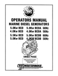
PARTS IDENTIFICATION
COOLANT FI
EXHAUST
MANI
FILL
THERMOSTAT
CONTROL
PANEL
DISTRIBUTOR
I
I
__- - - - THROTTLE
CONTROL
\\~,-----
OIL DRAIN HOSE
FLAME
SCREEN
FILTER
REAR
FUEL FILTER
RAW
WATER
PUMP
RIGHT SIDE
FUEL FILTER
FUEL
CHARGER
AIR BLEED
PETCOCK
__~"u .. FUSE
AC CIRCUIT
BREAKER
HEAT
EXCHANGER
ZINC ANODE
EXHAUST
SWITCH
FRONT
LEFT SIDE
,FLEXIBLE ISOLATED
MOUNTS
Engines & Generators
2
TESTING FOR OVERHAUL
HOW TO'DETERMINE ENGINE OVERHAUL PERIOD
Cause of Low Compression
ENGINE OVERHAUL
The following sections contain detailed information
relating to the major components and systems of the engine.
Included are disassembly and inspection instructions for the
guidance of suitable equipped and staffed marine engine service and rebuilding facilities. The necessary procedures
should be undertaken only by such facilities.
Generally, the time at which an engine should be overhauled
is detennined by various conditions such as lowered engine
power output, decreased compression pressure, and increased
fuel and oil consumption. The lowered engine power output
is not necessarily due to trouble with the engine itself, but is
sometimes caused by improper oil, clogged filters or a faulty
carburetor.
Additional detailed information and specifications are
provided in other sections of this manual, covering the
generator, alternator, starter. motof"engineadjllstments,
cooling pumps, etc.
The decrease in compression pressure is caused by many factors. It is, therefore, necessary to determine a cause or causes
on the basis of data produced by periodic inspection and
maintenance. Oil analysis on a seasonal basis is a good
means of monitoring engine internal wear. When caused by
worn cylinders or piston rings, the following symptoms will
occur:
1
2
3
4
5
DISASSEMBLY
1. Before disassembly and cleaning, carefully check for
defects which cannot be found after disassembly and
cleaning.
Low engine power output
Increased fuel consumption
Increased oil consumption
Hard engine starting
Noisy engine operation
2. Clean the engine exterior.
3. Perform disassembly in a proper order using proper tools.
Keep disassembled parts in order. Apply oil when neces. sary. Take special care to keep the fuel system parts fro~ .
intrusion of dust and dirt.
SERIAL NUMBE~ LOCATION~~ ~
These symptoms often appear together. Symptoms 2 and 4
can result also from improper fuel regulation or a faulty carburetor. They are caused also by defective electrical devices
such as the battery, starter or spark plugs. Therefore it is
desirable to judge the optimum engine overhaul time by the
lowered compression pressure caused by worn cylinders and
pistons plus increased oil consumption. Satisfactory combustion is obtained only under sufficient compression pressure.
If an engine lacks compression pressure, incomplete combustion of fuel will take place even if other parts of the engine
are operating properly. To detennine the period of engine
overhaul, it is important to measure the engine compression
pressure regularly. At the same time, the engine speed at
which the measurement of compression pressure is made
should be checked because the compression pressure varies
with engine rpm. The engine rpm can be measured at the
front end of the crankshaft.
FiII in the information
below for reference.
~~
f\ll
'~
~~~
~.'
The engine serial
t~(,~Ob').. ~,,!umber is st~mped
3?
. "\
~ \, mto the engme block.
~l
~
',<mo'-:;d~el~i~:~~~~~~~~~~
:
11
The engine
number ands~~al
number are printed
on a decal on the
engine manifold.
The generator serial
number is stamped
on the top of the
generator ILUL~~.LJ:~MIIIiI
NOTE: To test engine compression see the ENGINE
ADJUSTMENT section of this manual.
OVERHAUL CONDITIONS
Compression pressure tends to increase a little in a new
engine until piston rings and valve seats have been broken in.
Thereafter, it decreases gradually with the progress of wear
of these parts.
specijilcations are
on a decal
on the side of the
generator.
When decrease of compression pressure reaches the repair
limit, the engine must be overhauled.
An additional decal
is located on the top
of the generator
Iiousing.
The engine requires overhaul when oil consumption is high,
blowby evident, and compression values are at minimum or
below. Engine compression should be 178 psi (1260 Kpa) at
400 rpm. Wzth a limit 137 psi (860 /(paY. Pressure should not
differ by more than 14 psi (100 Kpa) between cylinders. See
ENGINE COMPRESSION in this manual.
Engines & Generators
3
BeG' GENERATOR TROUBLESHOOTING
This chart may be of assistance in determining the need for
an engine overhaul. For back-end troubleshoting, refer to the
BC GENERATOR ELECTRICAL TESTING section in this
manual.
The following troubleshooting chart describes certain
problems relating to engine service, the probable causes of
these problems, and the recommendations to overcome
these problems.
Problem
HARD STARTING
OR FAILURE TO START
SMOKY EXHAUST
VerificationJRemedy
Probable Cause
1. High exhaust pressure.
1. Install alarger diameter exhaust.
2. Timing belt.
2. Inspect timing be~-replace.
3. AC generator overload.
3. Remove loads before starting.
4. Check valve at fuel supply.
4. Repair or replace..
5. Defective starter.
5. Repair or replace starter.
6. Faulty fuel regulator.
6. Replace regulator.
7. Raw water in cylinders.
7. Failure of exhaust system or syphon break. Clear cylindersEngine may need overhaul.
WHITISH , PURPLE OR BLUE SMOKE
1. Excessive engine oil.
1. Correct oil level.
2. Excessive rise of oil into combustion chamber.
2. Engine overhaul.
a. Poor piston contact.
a. Check standam.
b. Seized piston ring.
b. Replace or clean.
c. Excessive piston-to-cylinder clearance.
c. Replace or correct.
d. Worn valve stem and valve guide.
d. Replace.
e. Low engine oil Viscosity.
e. Replace.
f. Excessive oil pressure.
f. Correct.
g. Piston rings are worn or unseated.
g. Engine overhaul.
3. Insufficient compression.
3. See LOW COMPRESSION; HARD STARTING.
BLACKISH OR DARK GRAY
EXCESSIVE OIL
CONSUMPTION
1. Poor compression.
1. See LOWCOMPRESSION.
2. Improper valve clearance.
2. Valve adjustment.
3. Insufficient intake air (air cleaner clogged).
3. Replace air cleaner.
4. Improper fuel.
4. Replace with proper fuel.
OIL LEAKAGE
1. Defective oil seals.
1. Replace oil seals.
2. Broken gear case gasket.
2. Replace gasket.
3. Loose gear case attaching bolts.
3. Retighten bolts.
4. Loose drain plug.
4. Retighten plug.
5. Loose oil pipe connector.
5. Retighten oil connections.
6. Broken rocker cover gasket.
6. Replace gasket.
7. Loose rocker cover attaching bolts.
7. Retighten attaching bolts.
OIL LEVEL RISING
ENGINE BACKFIRES,
MISFIRES
1. Dead cylinder.
1. Check compression.
2. Displaced or twisted connecting rod.
2. Replace connecting rod.
3. Worn piston ring.
3. Replace ring.
1. Incorrect valve clearances.
1. Adjust valves and clearances.
2. Valves are out of adjustment.
2. Adjust valves and clearances.
I~/WESTERBEKE
I
Engines & Generators
4
BCG ENGINE TROUBLESHOOTING
PROBLEM
ABNORMAL SOUND
OR NOISE
LOW COMPRESSION
EXCESSIVE FUEL
CONSUMPTION
KNOCKING
VERIFICATIO N/REMEDY
PROBABLE CAUSE
CRANKSHAFT AND MAIN BEARING
1. Badly worn bearing.
1. Replace bearing and grind crankshaft.
2. Badly worn crankshaft.
2. Grind crankshaft.
3. Melted bearing.
3. Replace bearing and check lubrication systern.
CONNECTING ROD AND CONNECTING ROD BEARING
1. Worn connecting rod big end bearing.
1. Replace bearing.
2. Worn crankpin.
2. Grind crankshaft.
3. Bent connecting rod.
3. Correct bend or replace.
PISTON, PISTON PIN, AND PISTON RING
1. Worn cylinder.
1. Rebore cylinder to oversize and replace piston.
2. Worn piston pin.
2. Replace piston.
3. Piston seized.
3. Replace piston and rebore cylinder.
4. Piston seized and ring worn or damaged.
4. Replace piston and rings.
VALVE MECHANISM
1. Worn camshaft.
1. Replace.
2. Excessive valve clearance.
2. Adjust.
3. Worn timing gear.
3. Replace.
4. Worn fan pulley bearing.
4. Replace.
MAIN ENGINE TROUBLES
1. Incorrect valve clearance.
1. Adjust valve clearance.
2. Inadequate contact of valve seat.
2. Lap valve.
3. Valve slem seized.
3. Replace valve and valve guide.
4. Broken valve spring.
4. Replace valve spring.
5. Compression leaks through cylinder head gasket.
5. Replace gasket.
6. Piston ring seized.
6. Replace piston and piston ring.
7. Worn piston ring and cylinder.
7. Overhaul engine.
S. Worn engine bearings.
S. Overhaul engine.
1. Noisy knocking.
1. See KNOCKING.
2. Smoky exhaust.
2. See SMOKY EXHAUST.
3. Moving parts nearly seized or excessively worn.
3. Repair or replace.
4. Poor compression.
4. See LOW COMPRESSION; HARD STARTING.
5. Improper valve timing.
5. Adjust.
6. Improper valve clearance.
6. Adjust.
INSUFFICIENT INTAKE AIR
1. Air intake obstructed.
1. Remove obstruction.
NOZZLE TROUBLES
1. Seized nozzle.
1. Replace.
2. Worn nozzle.
2. Replace.
ENGINE KNOCKS WITHOUT MUCH SMOKE
1. Main engine troubles.
a.Overheated cylinder.
a. See OVERHEATING; LOW OUTPUT.
b.Carbon deposits in cylinder.
b. Clean.
KNOCKING WITH DARK SMOKE
1. Poor compression.
LOW OIL PRESSURE
1. See LOW COMPRESSION; HARD STARTING.
1. Worn Bearings.
1. Engine overhaul replace bearings.
2. Relief valve malfunction.
2. Overhaul oil pump.
3. Clogged oil cooler/fdter.
3. Repair and replace.
4. Diesel dilution of the oil.
4. Injection pump repair.
Engines & Generators
5
GENERATOR/ENGINE DISASSEMBLY
DESCRIPTION
Unfasten the generator from its mounting rails or the
mounting rails from the platform and remove the generator
from the boat.
Once the generator is securely mounted on the work bench,
drain the engine oil and coolant.
Remove the starter motor. Disconnect and remove the wiring
harness, be certain to tag all the wiring -connections so you
can separate them.
The engine component of the BC generator is not as bulky or
heavy as most engines (approx. 75 lbs) so it can be
disassembled and repaired on a sturdy work bench. make
certain however that the engine is securely fastened so it can
not topple off the bench and that the bench also is secure and
can not tip over.
Set the generator breakers and panel switches in the off
position. Disconnect the AC wiring connections at the
terminal block/circuit breaker and unplug the harness at the
control pane. Disconnect the battery cable connections and
the engine ground cables.
Close off the raw water seacock and disconnect the raw
water components. Separate the exhaust at the water injection
elbow and disconnect the fuel supply.
Separate the generator back-end from the engine. Once the
housing is removed, the remaining generator components can
be disassembled from the engine back-plate.
NOTE: For servicing and testing of the back-end (generator),
refer to the GENERATOR section in this manual.
A CAUTION: Make certain the fuel lines are closed
ASSEMBLY
BOLTS
off and drained. Clean up all fuel and oil spills and
properly dispose of the rags.
STARTER
MOTOR
HOUSING
GENERATOR
TYPICAL BC GENERATOR
BACK-END ASSEMBLY
i:-REMOVE USING AN BMM (tt/t6') SOCKET
~ifl!(r? TO DRAIN THE OIL OR PUMP THE WARMED
OIL UP THRU THE HOSE.
GENERATOR BACK·END
SEE SPECIAL TOOLS FOR
DISASSEMBLING THE
GENERATOR COMPONENTS
COOLANT DRAIN
LOCATED JUST BELOW
THE INTAKE MANIFOLD
Engines & Generators
6
ENGINE ASSEMBLY
GENERAL INFORMATION
When installing gaskets that seal around water (coolant)
passages, coat both sides with WHITE SILICONE GREASE.
• Be careful not to mix bolts and nuts. Metric and S.A.E.
bolts are used on various engine assemblies.
Do not use sealant when installing a new gasket.
• During assembly, recheck clearances and insure that parts
are being assembled in their proper order and facing in the
correct direction in relation to the engine block, such as,
pistons, piston rings, bearings and bearing caps.
HIGH-COPPER ADHESNE SPRAYS are useful for holding a gasket in position during assembly.
Specialized gasket sealers such as HYLOMAR work well in
applications requiring non-hardening properties. HYL011AR
is particularly effective on copper cylinder-head gaskets and
resists fuel, oil , and water.
• Apply lubricating oil to moving parts during assembly.
Insure that moving parts, when assembled on the engine,
rotate or slide and are not subject to binding or
excessive tension.
NOTE: TAPE SEAlANTS should be used on pipe plugs and
fitting that connect water coolant passages.
• If !!here are mating marks scribed during disassembly,
reference them correctly for assembly.
• Use new gaskets, lockwashers, O-rings, packings and seals.
Bolts and Fasteners
• Tighten the bolts and nuts on important parts of the engine
to specified torques using a reliable torque wrench.
Lightly oil head bolts and other fasteners as you assemble
them. Bolts and other plugs that penetrate the water jacket
should be sealed with PERMATEX #2 or HIGH TACK.
• When required, use liquid sealants when required on nuts,
bolts and gaskets. Refrain from using tape sealants.
When assembling the flywheel, coat the bolt threads with
LOCTITE blue.
• Most gaskets and many bolt washers are asymmetrical,
make certain they are positioned properly.
LITHIUM based grease is waterproof, ideal for water pump
bearings and stuffing boxes.
Torquing Hardware
Antiseize compounds and thread locking adhesives such as
LOCTITE protect threaded components yet allow them to
come apart when necessary. LOCKTITE offers levels of
locking according to the job.
Prevent mechanical damage by running fasteners down in
three steps-1/2, 213, and 111 torque. Exceptions are torque-toyield bolts and rocker arm shaft fasteners. The former are
torqued as indicated. The latter-rocker shaft fasteners-should be
brought down in very small increments, working from the
center bolts out. Gaskets, especially head gaskets, might be
damaged during assembly, they should be positioned with great
care. See TORQUE SPECIFICATIONS thru out this manual.
Heavily oil all sliding and reciprocating components, always
use clean engine oil.
Sealants and Lubricants
Oil based PERMAlEX #2 and its HIGH TACK equivalent are
excellent all purpose sealers. They are effective in just about
any joint in contact with coolant, raw water, oil, or fuel. A light
coating of oil or LIQUID TEFLON can be used on rubber
gaskets and a-rings.
LOCTITE hydraulic red sealant should be used on oil adapter
hoses and the oil filter assembly.
Coat both surfaces of the oil pan gasket with high temp RED
SILICONE SEALER.
Engines & Generators
7
TIMING BELT DISASSEMBLY
NUMBERS INDICATE THE
SUGGESTED ORDER OF
DISASSEMBLY
9 CAMSHAFT SPROCKET
TORQUE 1 - 9 FT-LBS
10-12Nm
\
TORQUE 1 - 9 Ft-Lbs
10-12Nm
\
1 TIMING BELT
COVER A
3 ACCESS CDVER~
13 CRANKSHAFT 10 FLANGE NUT
12 CRANKSHAFT
SPROCKET
BOLT
TORQUE 98 - 105 Fr-LBS
135 -145 Nm
TORQUE 36 - 40 FHBS
[50 -56 NmJ
TIMING BELT
COVER C
TIMING BELT ADJUSTMENT,
INSPECTION AND REPLACEMENT
CAN BE PERFORMED WITH
ENGINE IN THE BOAT
(::::j.<,--....u..,~...,-~----'-'2.6 In [65 mm]
INSTRUCTIONS FOR INSPECTING AND REPLACING
THE TIMING BELT
WESTERBEKE requires as normal maintenance, replacing
the timing belt after 1000 engine operating hours. The timing
belt should always be replaced during an engine overhaul.
ROD 0.3110 [8 mm]
The adjustments, inspection, and replacement procedures
may be performed without removing the generator from the
boat THE TIMING BELT PART NUMBER IS #043036
Timing Belt Removal
3, Loosen the timing belt tensioner nut
4. Move the timing belt tensioner toward the water pump,
and temporarily tighten the nut to hold the tensioner in
that position.
1. Tum the crankshaft clockwise to align the timing mark on
the camshaft sprocket and timing belt rear cover.
NOTE: Always tum the crankshaft clockwise.
TIMING MARK -=>~-/'
2. Remove the plug on the left smface of the cylinder block
and insert a rod with a diameter of 0.31 in (8 mm) to lock
the counterbalance shaft.
NOTE: Be sure to use an inserting rod with a diameter of
0.31 in (8 mm).
Engines & Generators
8
CRANKSHAFT
SPROCKET
TIMING BELT DISASSEMBLY
5. Remove the timing belt.
Crankshaft Bolt Removal
NOTE: If the timing belt is to be reused, draw an arrow on
the belt to indicate the direction of rotation (clockwise).
1. Lock the crankshaft in position.
NOTE: Do not turn the crankshaft.
2. Remove the crankshaft bolt.
Timing Bell Inspection
Replace the belt if any of the following conditions exist:
• HllI'dening of the back rubber, leaves no indent when
pressed with fingernail (back side is glossy).
• Cracks on rubber back.
• Cracks or peeling of canvas.
• Cracks on tooth bottom.
Camshaft Sprocket Removal
• Cracks on belt.
• Abnormal wear of belt sides. The sides are normal if they
are sharp as if cut by a knife.
1. Remove the camshaft sprocket bolt without turning the
camshaft.
• Abnormal wear on teeth.
• Tooth missing and canvas fiber exposed.
CRACKS ON EDGE
SPROCKET BOLT
HARDENING
~
~
'v.
Oil Pump Sprock~t Flange Nut Removal
F
PEELING
1. Remove the plug from the left side of the cylinder block.
2. Insert an 0.31 in (8 mm) diameter round bar to lock the
counterbalance shaft.
3. Remove the oil pump sprocket flange nut.
00
ROUNDED EDGES
FLUFFY STRANDS
00
$
CRACKS ON UNDERSIZE
CRACKS ON TOP
Tensioner Inspection
TOOTH MISSING
CANVAS EXPOSED
1. Replace the tensioner if the pulley binds, rattles or is noisy
when turned.
OIL PUMP SPROCKET
Engines & Generators
9
ENGINE TIMING BELT
Flange Installation
Tensioner Spring/Timing Tensioner Installation
1. Mount the flange so that its side shown by the heavy
arrow in the illustration faces toward the sprocket.
1. Install the tensioner spring and timing belt tensioner.
2. Hook the tensioner spring onto the bend of the timing belt
tensioner bracket and the stopper pin on the cylinder block.
3. Move the timing belt tensioner as close as possible to the
water pump; temporarily tighten the tensioner nut.
R--rri~
-~
WASHER
Crankshaft Bolt Installation
1. Lock the crankshaft.
NOTE: Do not tum the crankshaft.
2. Tighten the crankshaft bolt to the specified torque.
Oil Pump Sprocket Flange Nut Installation
1. Insert the round _bar into the plug hole in the left side of
the cylinder block to keep the counterbalance shaft from
turning.
Timing Belt Installation
1. Align the triangular marking on the camshaft sprocket
with a marking on the timing belt rear cover.
2. Install the oil pump sprocket.
2. Align the notch in the crankshaft sprocket flange with the
marking on the front case.
3. Align the triangular marking on the oil pump sprocket
with the marking on the front case, and then insert a 2.56 in.
(65 mm.) or longer, 0.31 in (8mm.) diameter round bar into
the plug hole in the left side of the cylinder block.
MARK ON TIMING
BELT REAR COVER _ _N'-P
Camshaft Sprocket Bolt Installation
1. Tighten the bolt to the specified torque.
CAMSHAFT BOLT TORQUE 58 - 72 Ft-Ibs (80 -100 Nm)
NOTCH IN CRANKSHAFT
SPROCKET
MARK ON FRONT CASE
SPROCKET BOLT
Engines & Generators
10
ENGINE TIMING BELT
8. Tum the crankshaft clockwise by nine camshaft sprocket
teeth (81°) to align the timing mark on the camshaft
sprocket with the tensioner set mark on the timing belt
rear cover.
At this time, check that the moveable range of teeth on the
oil pump sprocket is according to specifications.
STANDARD VALUE: 410 5 teeth in forward direction.
1 to 2 teeth in reverse direction.
A CAUTION: This operation is performed to give a
proper tension to the timing belt, so do not tum the
crankshaft counterclockwise and push the belt to
check the tension.
TENSIONER SET MARK
4. If the movable range of the teeth on the oil pump sprocket
exceeds the specified range, correct as follows:
a. Pull out the round bar from the plug hole in the left
side of the cylinder block.
h. Turn the oil pump sprocket one tum at a time until the
round bar can again be inserted.
9. Make sure that the timing belt teeth are engaged with the
camshaft sprocket teeth along the portion of the sprocket
shown by the curved arrow in the illustration below. Then
tighten the tensioner nut.
c. Check that the movable range of the oil pump sprocket
is in the specified value.
lO.Pull the timing belt in the center of the tension side
toward the sealing gasket line for the belt cover, as illustrated. Make sure that the clearance between the back of
the belt and the sealing line is the standard value.
5. Set the timing belt over the crankshaft sprocket and then
over the oil pump sprocket and camshaft sprocket, in that
order.
NOTE: Ensure that the tension side of the timing belt is not
slack. Keep the round bar inserted until the timing belt has
been placed. After this step, be sure to remove the round bar.
STANDARD VALUE: O.47in. (12mm)
SEALING GASKET
LINE
6. Apply counterclockwise force to the camshaft sprocket to
make the belt taut on the tension side, and make sure that
all timing marks are lined up.
0.47 In [12 mmJ
CAMSHAFT SPROCKET
TENSION SIDE
1l.PulI out the rod from the plug hole on the left surface of
the cylinder block and apply the specified sealant. Then
tighten the plug to the specified torque.
Specified sealant value: 3M AID Part No. 8660 or
equivalent.
7. Loosen the temperorarily tightened tensioner nut on the
water pump side 1 or 2 turns, and tension the belt making
use of the spring force.
TIGHTENING TORQUE: 11-16 ft.lbs. (15-22 Nm)
Engines & Generators
11
ENGINE DISASSEMBLY
FILTER
~
Disconnect and drain the oil hoses. remove, clean and inspect
the oil gallery/filter assembly, replace the filter.
FUEL FILTER
ASSEMBLY
Remove the thermostat assembly and clean the interior
chambers. Inspect the seals in the pressure cap when
reassembling. Replace the thermostat and gasket.
Remove the fuel filter assembly. Drain and inspect the hoses.
Inspect the O-ring and replace the filter element.
GASKET
APPLY SEALANT
TO GASKET WHEN
INSTALLING
Remove the engines coolant pump. For servicing, refer to
COOLANT PUMP.
Detach and remove the ignition wires, the distributor and
spark plugs. Refer to DISTRIBUTOR DISASSEMBLY in this
manual.
THERMOSTAT
See ENGINE ADJUSTMENTS for information on ignition
wires and spark plugs.
Loosen the raw water pump, remove the drive belt and then
remove the raw water pump.
RAWWATEfi
PUMP
SPWFtU~· •
..-v- WESTERBEKE
Engines & Generators
12
\
4CYLINDER HEAD BOLTS.
TORQUE 43 - 51 FT-LI3S
60-10Nm
'\
~~.
r.
-~
7RETAlNINGLOCK~
.~
8 VALVE
S:~RIN:~~
~
15
RETAIN/
NUMBERS INDICATE THE
SUGGESTED ORDER OF
DISASSEMBLY
9 VALVE SPRING
SEAL
10 VALVE SPRING
CYLINDER HEAD
19VALVEGUIDE-
If
INTAKE VALVE SEAT
16 EXHAUST VALVE----4
8
6
CYLINDER HEAD BOLTS
LOOSENING SEQUENCE
REMOVING THE CYLINDER HEAD
FROM THE CYLINDER BLOCK
Disassemble the cover bolts as shown above, taking care not
to lose the washer and insert. Remove the rocker cover and
rocker cover gasket.
Loosen each of the cylinder head bolts, a little at a time so
as to avoid the possibility of distorting the cylinder. Repeat
several times until the bolts are unfastened. Follow the
sequence shown in the diagram.
Remove the cylinder head and the cylinder head gasket.
Engines & Generators
13
CYLINDER HEAD AND VALVES
VALVE ASSEMBLY INSPECTION
Valve SteroNalve Seat
Use pliers to remove the valve stem seals. Do not reuse the
stem seals.
If the valve stem is bent or worn, replace the valve. Check
contact between the valve and valve seat by applying a thin
coat of Prussion Blue (or Redhead) on the valve seat contact
face, then insert the valve into the valve guide and press-fit
the valve on the valve seat. Do not rotate the valve.
Check if the valve seat contact face contacts the center position 0f the valve contact face. If it is not correct concentric,
correct the valve seat If the margin is out of the limit, replace
the valve.
THICKNESS OF VALVE HEAD MARGIN
standard
Intake
0.0391n (1.0mm)
Exhaust
0:051In (1.3mm)
CYLINDER HEAD INSPECTION
Before cleaning check the cylinder head for water leaks,
cracks and other possible damage.
Clean by completely removing the oil, scaling, carbon and
sealant After flushing the oil passage, blow air thru to ensure
that no portion of the oil passage is clogged.
To check the cylinder head bottom surface for flatness and
distortion, as indicated in the diagram, use a straight edge
and a feeler gauge. If distortion exceeds the limit correct
by grinding.
Limit
0.02010 (0.508mm)
0.031 In (0.787mm)
----r--
CONTACT WITH
VAlVE SEAT
[to be at center
of sea
VALVE
LENGTH
VALVE HEAD
THICKNESS [MARGIN]
.L
VAlVE LENGTH: Intake 3.6010 (100.6mm)
'Exhaust 3.96810 (100.8mm)
VALVE SEAT WIDTH OF CONTACT
standard
0.03510 - 0.051 (0.9 -1.3mm)
Valve Spring
Measure the free height of the valve spring and replace the
spring if it is out of limit
VALVE SPRING FREE LENGTH
Standard 1.823In {46.3mm)_ _ _ _ Umlt
CYLINDER HEAD FLATNESS
standard O.02Oln (0.05mm)
Limit 0.079 (0.2mm)
CYLINDER HEAD GRINDING LIMIT
0.079In (0.2mm)
Total resurfacing depth of cylinder head and block
CYLINDER HEAD HEIGHT (NEW)
4.287 - 4.2951n (108.9 -109.1mm)
A
1.783ln (45.3 mm)
MEASURING VAlVE
SPRING FREE LENGTH
Also check the spring for squareness and if it exceeds the
limit replace the spring.
VAlVE SPRING SQUARENESS
Standard less than 2°
Limit
4°
Refer to the StandardslLimits chart for additional
specifications on valves.
CAUTION:
No more than 0.079In (O.2mm) of
stock may be removed from the cylinder head and
cylinder block mating surfaces in total.
See the STANDARDS AND UMITS CHART for cylinder
head rework dimensions of the valve seat hole.
TESTING SQUARENESS/ANGLE
Engines & Generators
14
CYLINDER HEAD AND VALVES
Valve Stem and Guides
VALVE STEM
SEAL INSTALLER
~
VALVE STEM
SEAL
Valve Springs
MEASUR;NG VALVE
STEM DIAMETER
Install the valve spring with it's enamel coated side toward
the rocker arm side.
~~~~ ~;---SPIRINIi RETAINER
VALVE STEM SEAL TO VALVE GUIDE CLEARANCE
Standard
Intake
0.0008 - 0.0020in (0.7 - 0.05mm)
Exhaust
0.020 - 0.0033in (0.50 - 0.085mm)
Limit
Intake
0.00391n (O.10mm)
Exhaust
O.0059in (0.15mm)
VALVE STEM OUTER DIAMETER
Intake
Standard
Exhaust
ENAMel
COATED
SIDE
0.2585 - 0.25911n (6.565 - 6.580mm)
0.2571 - 0.2579in (6.330 - 6.550mm)
SEAT
Use the valve spring compressor to compress the valve
Valve Seat Reconditioning
::,::: .tho v,"ve s;;;omP"~' remove the
Before correcting the valve seat, check for clearance
, between the valve guide and the valve. replace the valve
guide if necessary.
To recondition, use a valve and seat cutter and a pilot or a
seat grinder, repair so that the seat width and seat angle are
the specified configuration.
After correction, the valve and the valve seat should be
lapped with lapping compound.
I J VALVE SPRING
f
COMPRESSOR
REMOVING
RETAINER
LOCKS
VALVE SEAT CONTACT WIDTH
.035 - .051 in [0.9 -1.3 mml
Cylinder Head Gasket
Clean the residue of gasket and oil from the gasket mounting
surface of the cylinder block and the cylinder head.
Place a new cylinder head gasket on the cylinder block
facing its identification mark upward.
INSTALLATION
Valve Stem Seal
Install the valve spring seat, then using the valve stem seal
installer, install a new stem seal to the valve guide.
Do not use the old valve stem seal.
NOTE: Use the installer tool to insert the stem seal, improper
installation can cause oil to leak into the cylinder.
CYLINDER HEAD GASKET
Engines & Generators
15
CYLINDER HEAD AND VALVES
Cylinder Head Bolts
Tighten the cylinder head bolts in the order shown in the diagram using a stepped-up tightening torque.
INTAKE SIDE
1. Temporarily tighten the bolts in numerical order to 1422ft-lbs (20 - 30 Nm).
2. Tighten the bolts again in numerical order to 29 - 36ft-Ibs
(40- 50Nm).
3. Tighten the bolts in numerical order to the specified
torque.
CYLINDER HEAD TORQUE
ENGINE FRONT
43 -51fHbs (50- 70Nm)
Rocker Cover
Install the rocker cover using a new gasket (slightly coat both
sides with clean oil). Gradually tighten the cover bolts to the
specified torque making certain the cover gasket is positioned
properly.
EXHAUST SIDE
CYLINDER HEAD BOLTS
TIGHTENING SEQUENCE
ROCKER COVER BOLT TORQUE (5mm BOLT)
2.9·5.2 ft·lbs (4 ·7Nm)
Engines & Generators
16
CAMSHAFT AND ROCKER ARMS
TORQUE 21 - 25 FT-LBS
TORQUE 21 - 25 Ft-Lbs
21-35Nm
NUMBERS INDICATE THE
SUGGESTED ORDER OF
DISASSEMBLY
2! . 35 Nm
----,
~
il
®
10 ROCKER ARM
EXHAUST
1 ROCKER ARM, ROCKER
SHAFT ASSEMBLY
14 CAMSHAFT
12CAMSHAFT
OILSEAL
®
~
INSPECTING THE CAMSHAFT
CAMSHAFT HEIGHT
Intake
#1
#2
#3
Exhaust
#1
#2
#3
1. Visually inspection the camshaft for cracks and damage.
If necessary, replace the camshaft.
NOTE: lfthe damage is slight, you may be able to correct the
camshaft with an oil soaked fine emery grindstone. Take
special care to not damage the original cam/arm.
2. Inspect the camshaft journal and, if wearing exceeds the
limit, replace the camshaft.
STANDARD
1.38151n (35.09mm)
1.38071n (35.07mm)
1.38031n (35.06mm)
1.38391n (35.15mm)
1.38311n (35.13mm)
1.38541n (35~19mm)
LIMIT
1.36181n (34.59mm)
1.3610in (34.57mm)
1.3606in (34.56mm)
1.3642in (34.65mm)
1.3634in (34.63mm)
1.3657in (34.69mm)
CAMSHAFT JOURNAL DIAMETER
STANDARD '.6118 - 1.61241n (40.940 - 40.955mm)
C:C-~O'
CHECK CAM LOBES FOR WEAR &DAMAGE
CHECK JOURNAL BEARINGS
FOR WEAR DAMAGE
HEIGHT
~.
MEASURING
CAMSHAFT HEIGHT
4. Inspect the clearance between the camshaft journal and
the camshaft support bore as follows:
a. Measure the camshaft journal diameter and the
camshaft support bore.
Camshaft
NOTE: lfthe Journal is seized, also check the cylinder head!
h. Calculate the clearance and replace the camshaft or
cylinder head if the clearance exceeds the limit.
3. Measure the cam height and, if it is less than the limit,
replace the camshaft.
BEARING OIL CLEARANCE
STANDARD 0.0018 - 0.0033in (.045· 0.085mm)
Engines & Generators
17
CAMSHAFT AND ROCKER ARMS
Rocker Arm
3. Measure the end play of the camshaft by inserting a
feeler gauge in the gap between the rear of the thrust
plate and the new front camshaft journal.
Check each component part of the rocker arm assembly and
carefully inspect the individual rockers where the arrows
indicate.
VALVE
Standard
Limit
0.236 - 0.0551 in (0.06 - 0.14mm)
0.1181n (O.3mm)
ROCKER ARM
INSPECTION
Inspecting Clearance Rocker Arm And Shaft
Check the clearance between the rocker arm and shaft and, if
it exce,eds the limit, replace the rocker arm or shaft.
ROCKER ARM CLEARANCE (ROCKER ARM TO SHAFT)
Standard
0.0005 - O.0017in (D.012 - O.043mm)
Limit
0.004in (O.1mm)
4. Using the oil seal installer tool, install the front oil seal in
the cylinder head,
Rocker Shaft
1. Inspect the rocker shaft where the rocker arms sit for
water and damage. Replace the shaft if worn.
2. Measure the shaft length and the shaft outer diameter
(O.D.). If the shaft fails to meet the standards, replace
the shaft.
ROCKER SHAFT LENGTH
Standard 9.134in (232mm)
ROCKER SHAFT 0.0. Standard 16.985 • 16.988in (0.6687 - 0.6693mm)
~
OIL HOLES
~~II Or]
J
5. Install the rocker armlrockershaft assembly. Install the
rocker shaft so the portion shown in the diagram is
located on the front.
OIL HOLES
BOLT HOLE
INSTALLATION
1. Apply a coating of engine oil to the camshaft journals
and cams and insert the camshaft through the rear of the
cylinder head.
2. Install the camshaft thrust plate as shown in the diagram
tighten the bolts to the specified torque.
THRUST PLATE BOLTTORQUE
FRONT
BOTTOM VIEW
7 - 91t-lbs (10 -12Nm)
OIL HOLE
6. Tighten the rocker arm shaft bolts (4 bolts) uniformly and
then to the specified torque.
TORQUE
BOLT
ROCKER ARM SHAFT BOLT TORQUE
Engines & Generators
18
21 • 25ft·lbs (29 - 35 Nm)
PISTONS AND CONNECTING RODS
111 PISTON RING
ARROW
FRONT MARK
112 PISTON RING
gOIL RING
BOLT
STOPPER
NOTCH
CYLINDER
NUMBER
-,
NUMBERS INDICATE THE
SUGGESTED ORDER OF
DISASSEMBLY
REMOVING THE CONNECTING RODS/PISTONS
Tum the engine over and remove the connecting rod bearing
caps and the connecting rod bearings, note the markings on
the bearing cap and keep the disassembled parts (connecting
rod, rod cap, piston, etc. classified by cylinder. If the marks
are worn away be certain to remark them.
Disassemble the Pistons
Using the ring remover, remove the piston rings. While
removing the piston rings, note the order they are removed
and which side of the ring faces the piston crown.
Remove the Piston Pins
Insert the special tool, push the rod, and guide B into the
piston pin then set the piston and connecting rod assembly
on the pin setting base. Make certain that the front (arrow)
stamped on the piston top surface faces upwards. Using a
press, drive out the piston pin.
11 PISTON RING
\~~~
NOTE: Keep the disassembled piston, piston pin and
connecting rod in order according to the cylinder number.
Engines & Generators
19
PISTONS AND CONNECTING RODS
Check the piston ring for damage, wear, seizure and bends
replacing the rings if anything unusual is noted. Always
replace the piston rings when installing a new piston.
PISTON PIN INSPECTION
Reinsert the piston pin into the piston hole with your thumb..
You should feel a slight resistance, if the bore is misaligned·
the pin will click or bind as it enters. Try the pin from both
sides. Replace the piston if the pin can be too easily inserted
or if there is excessive play.
FEELER GAUGE
NOTE: The piston pin and piston are replaced as an assembly.
Measure the outside diameter of the piston pin.
PISTON PIN 0.0.0.6300 - 0.6302in (16.001 -16.007mm)
RING SIDE
CLEARANCE
Check the clearance between the piston ring and the ring
groove, if it exceeds the limit, replace the rings, the piston
or both.
Pistons
Check the piston surfaces for wear, seizure, cracks and
streaking. If any damage is evident, replace the piston.
Inspect the oil return hole in the oil ring groove and the oil
hole in the piston boss. Clean the piston if these are clogged.
Check the piston pin hole for signs of seizure or damage.
Replace the piston if damage is evident Measure the piston
diameter at 90° (perpendicular) to the pin bore axis.
PISTON RING SIDE CLEARANCE
Standard
0.0012' 0.0028in (0.03 - 0.07mm)
No.1 ring
0.0008· 0.0024in (0.02· 0.06mm)
No.2 ring
Connecting Rod Bearing
Visually check the surface of the bearing. Replace those
which are lopsided, streaked or seized. When streaks or
seizure are excessive, check the crankshaft. If damage is
discovered on the crankshaft, either replace it or reuse after
undersize machining. If the connecting rod bearing indicates
severe thermal damage, replace the bearing.
PISTON 0.0.2.5579 - 2.55911n (64.97 - 65.00mm)
If the piston diameter is less then the standard replace
the piston.
NOTE: The piston and piston pin are replaced as an assembly.
Measure the inner diameter of the connecting rod bearing
and the outer diameter of the crankshaft pin. If the gap (oil
clearance) exceeds the limit, replace the bearing, and, if necessary, the crankshaft...or undersize machine the crankshaft
and replace the bearings with an appropriate undersize type.
Piston Rings
Insert the piston ring into the cylinder bore placing it against
the top of the piston head and pressing it in. When it marks a
right angle, measure the piston ring gap with a feeler gauge.
When the gap is too large, replace the piston ring.
PISTON RING GROOVE
Standard
No.1
0.0480 • 0.04881n (1.22 ·1.24mm)
No 2
0.0476 - 0.04841n (1.21 • 1.23mm)
Oil
0.1108 -0.1116In (2.815 - 2.835mm)
PISTON RING END GAP
Standard
limit
No.1
0.0059· 0.01181n (0.15 - 0.30mm) 0.81n (0.0315mm)
No.2
0.0138· 0.01971n (0.35 - 0.50mm) 0.8in (0.0315mm)
Oil
0.008·0.028In (0.2 - 0.7mm)
1.Oin (0.0394mm)
CONNECTING ROD BEARING OIL CLEARANCE
Standard
0.009 - 0.00201n (0.022 - 0.052mm)
CONNECTING ROO __......... ....
PISTON
PISTON RING GAP
Limit
0.00471n (0.12mm)
0.00391n (0.10mm)
Engines & Generators
20
Limit
0.0041n (0.1mm)
PISTONS AND CONNECTING RODS
Oil Ring
NOTE: See Crankshaft/Bearing section for measuring the oil
clearance with a Plastigauge.
Assemble the oil ring spacer into the piston ring groove.
Then, after assembling the upper side rail, assemble the
lower side rail.
Use a rod aligner to check the connecting rod for bend and
twist.
CONNECTING ROD BEND LIMIT
D.DD4in (D.OSmm)
NOTE: There is no difference between the upper and lower
side rails or the spacers. //~~/-
m
SIDE RAIL
~~.,....,.-
'---.J-1~
SPACER
The chart below identifies the color coding on new spacer
and side rails according to size.
SPACER AND SIDE RAIL CODING
SIZE
Color Identification
S.lO.
D.DD98in (O.2Smm) Oversize
D.D197in (D.SDmm) Oversize
O.029Sin (0.7Smm) Oversize
0.D394in (1.DDmm) Oversize
CONNECTING ROD TWIST LIMIT
D.004in (0.1mm)
CONNECTING ROD BIG END TO CRANKSHAFT SIDE CLEARANCE
Standard
0.0039 - D.DD9Sin (0.10 - D.2Smm)
CONNECTING ROD CENTER LENGTH
Standard
4.0138 - 4.D178in (101.9S -1D2.0Smm)
Two Blue LInes
One Red Line
Two red lines
One Yellow Line
Install the three-piece oil ring in the piston. Then, make
certain the side rails move smoothly in both directions. The
side rail my be easily installed by pushing it in with your
finger after fitting the one end over the piston groove. Do not
use an expander ring on the oil ring.
ASSEMBLY
Piston Connecting Rod, Piston
END OF SIDE RAil
Using the special tool (pin setting base) assemble the
piston and connecting rod and press-in the piston pin. First,
install the piston pin into the special tool,
PUSH
ROD
Piston Rings
Use a piston ring expander and install the piston rings with
the marker and size marks facing up toward the piston top.
Notice the difference in shapes between No.1 and No.2 ring.
GUIDE A
Set up the piston and connecting rod on the piston pin setting
base. Make sure that the front marks are facing up. Apply
engine oil to the outer circumference of the piston pin and
insert the pin, Guide A and the push rod (assembled) into the
piston and connecting rod.
f..---...,/-"
~~1I2PISTONRING
Using a press, load the push rod top end and press-fit the
piston pin in the connecting rod. The piston pin is press
fitted in the specified position by press-fitt~ng the Guide A
bottom end surface until it is seated on the bottom surface of
the base. If the press-fitting load is out of the specification,
replace the pin (piston assembly) or connecting rod, or both.
PISTON PIN PRESS-FITTING LOAD
PISTON RING
1102 - 33071bs (SDDD -15DONm)
Engines & Generators
21
PISTONS AND CONNECTING RODS
Installing the Piston Assembly
Apply an ample amount of oil to the outside surfaces of the
piston and the piston rings. Position the piston rings and oil
ring (side rail spacer) end gaps as shown.
NO.2
~
SlDERAIL
FRONT
NO.3
NO.'1
+II
~
#2 SPACER
~
r - - - - N O . 1 ARM
/J
-;::::?
CRANKSHAFT PIN DIAMETER
Journal Diameter
Identification marks
1.4171 -1.4173in (35.995 - 36.ooomm)
(1) 1/\
1.4167 -1.4171In (35.985 - 38.995mm)
(2) G
1.4165 - 1.4167in (35.980 - 35.985mm)
(3) C
'-SIDE RAIL
Insert the piston and connecting rod assembly into the
cylinder, working from the arrow mark on the piston top
toward the camshaft spx;ocket side.
CONNECTING ROD BIG END INNER DIAMETER
Big End Inner Diameter
Identification Marks
1.5354 -1.5356In (39.000 - 39.005mm)
1.5356 -1.5360in (39.005 - 39.015mm)
I
o
1.5360 ·1.53~2In (39.015' 39.020rnrn)
II
FRONT
CONNECTING ROD BEARING THICKNESS
Bearing Thickness
Identification Color
0.0586 • 0.0588in (1.488 -1.493mm)
Brown
0.0588 - 0.05901n (1.493 -1.498mm)
0.0590 - 0.0592in (1.498 -1.503mm)
Blue
ARROW
MARK
Securely pressing the piston ring with the ring band, insert
the piston and connecting rod assembly into the cylinder.
Keep in mind that the piston ring may be damaged if hit too
strongly.
CONNECTING ROD BEARING SELECTION TABLE
Connecting Rod Bearing
Crankshaft Pin
Identification Marks
Identification Marks
Brown
I
(1) 1/\
Brown
1I
PISTON RING
BAND INSTALLER
m
(2)
B
I
m
(3)
[
Brown
]I
I
][
m
Crankshaft/Bearing Assembly
Blue
Blue
Blue
IDENTIFICATION
COLOR
When the bearings are to be replaced, select the appropriate
bearings for assembly according to the identification marks
for the crankshaft and the connecting rod.
...
IDENTlFICATlO
MARK
CRANKSHAFT
CONNECTING ROD
STOPPER'
NOTCH
Engines & Generators
22
CYLINDER
NUMBER
PISTONS AND CONNECTING RODS
Installing the Connecting Rod Bearing Caps
Since the connecting rod cap bolts and nuts are torqued
using the plastic area tightening method, the bolts should be
examined before reuse. If the bolt threads are "necked
down". the bolt should be replaced.
Necking can be checked by running a nut with fingers to the
full length of the bolt threads. If the nut does not run
smoothly, the bolt should be replaced.
Before installation of each nut, apply clean engine oil to the
thread portion and bearing surface of the nut.
Install each nut to the bolt and tighten it with your fingers.
Then tighten the nuts alternately to install the cap properly.
Tighten the nuts to the proper torque.
CAP NUT TIGHTENING TORQUE
11+90· turn (15Nm +90· turn)
A CAUTION: If the cylinder head has been installed
before installing the connecting rod cap nut, remove
the spark plugs.
Make a paint mark on the head of each nul Make a paint
mark on the bolt end at the position 90° to 100° from the
paint mark made on the nut in the direction of the tightening
nul
Give a 90° to 100° tum to the nut and make sure that the
paint mark on the nut and that on the bolt are in alignment.
If the nut is turned less than 90°, proper fastening
perfonnance may not be expected. When tightening the nut,
rum it sufficiently.
If the nut is overtightend (exceeding 100°), loosen-the nut
completely and then retighten it by repeating the tightening
procedure.
Engines & Generators
23
FRONT CASE I COUNTERBALANCE SHAFT AND OIL PAN
GASKET
ENGINE BLOCK
'-1
TORQUE 6 -7 R-Lbs
NUMBERS INDICATE THE
SUGGESTED ORDER OF
DISASSEMBLY
11 FRONT
OIL SEAl.
5 OIL PUMP COVER
CONFIGURAnON
OF FRONT CASE
ASSEMBLY
"
----------------------------~---------~---;~--------~
OIL PAN REMOVAL
2. Remove the oil pump cover and gasket. Discard
the gasket
3. Remove the oil pump driven gear tightening flange bolts
. to release the counterbalance shaft.
4. Remove the counterbalance shaft. Drive it from the front
Remove the oil drain hose assembly. Remove the oil pan
bolts and then use the special tool to break the pan seal.
IL PAN GASKET TOOL
COUNTERBALANCE SHAFT REMOVAL
1. Remove the plug on the cylinder block and insert an
0.32in (8mm) rod into the hole to lock the
counterbalance shaft.
FLANGE BOLT
OIL PUMP DRIVEN
GEAR
Engines & Generators
. 24
FRONT CASE I COUNTERBALANCE SHAFT AND OIL PUMP
FRONT CASE· INSPECTION
4. Using a special tool drive the counterbalance shaft front
bearing from the cylinder block.
Check the front case for cracks or other damage also inspect
the oil holes. If the oil holes are clogged, use compressed air
or solvent to clean them out
EARING REMOVER TOOL
S. Use the same tool and drive the counterbalance shaft rear
CRANKSHAFT
FRONTOtL
SEAL
bearing from the cylinder block.
CRANKSHAFT FRONT OIL SEAL • INSPECTION
Check the oil seal for wear and damage. Inspect the oil seal
lip for hardening. If there any signs of wear, replace the seal.
OIL PUMP ASSEMBLY· INSPECTION
COUNTERBALANCE SHAFT
Fit the oil pump gear into the cylinder block. then, using a
feeler gauge, check the clearance with the body at the points
indicated in the diagram below.
DRIVEN GEAR BODY CLEARANCE STANDARD
A.
0.0161 - O.0266ln (0.410 - O.675mm)
B.
0.0051- O.oo69ln (0.130 - 0.175mm)
DRIVE GEAR BODY CLEARANCE STANDARD
C.
0.0173 - 0.02761n (0.44 - 0.70mm)
D.
0.0059 - O.OTIln (o.150 - 0.195mm)
DRIVEN GEAR SIDE ClEARANCE .0024 - 0.00471n (0.06 - 0.12mm)
DRIVE GEAR SIDE CLEARANCE
0.0027 - 0.0051 In (0.07 - 0.13mm)
COUNTERBALANCE SHAFT· INSPECTION
Inspect the oil holes for clogging and clean if necessary.
Inspect the shaft journal for seizure. damage and its contact
with the bearing. Check the counterbalance shaft oil
clearance. Replace the counterbalance shaft if it fails to meet
the standards.
Using a straight edge, check the side clearance at the point
indicated in the illustration with a feeler gauge.
There should be no uneven wear on the contact surfaces of
the cylinder block or on the pump gear side of the pump
COUNTERBALANCE SHAfT STANDARDS
Front Journal Diameter
0.7869 - 0.78741n (19.987 - 20.DOOmm)
Rear Journal Diameter
1.7317 -1.7322In (43.984 - 44.DDOmm)
Front Journal 011 Clearance 0.0014· 0.00271n (0.035 - 0.068mm)
Rear Journal 011 Clearance 0.0014 - 0.00281n (0.035 - 0.071mm)
~--DRIVE
GEAR
Engines & Generators
25
FRONT CASE I COUNTERBALANCE SHAFT AND OIL PUMP
INSTALLATION
Crankshaft Oil Seal
Counterbalance Rear Bearing
1.
1. Install the special tool guide pins (bearing Installer) in the
tapered hole of the cylinder block as shown.
~()r---.,
OILHOL
\
~\
~
J
r
()r
BEARING
Front Case Assembly
2. Mate the ratchet ball of the bearing in the oil hole of the
rear bearing and install the bearing in the bearing
installer.
3. Apply clean engine oil to the outer circumference of the
bearing and the bearing hole in the cylinder block.
4. Insert the installer by mating it with the guide pins and
press-in the bearing.
'J ~
GUIDE PIN ____"'.H'
~
Install the front case assembly through the gasket and tighten
the bolts to the specified torque.
FRONT CASE BOLTS TORQUE
6 -7ft.lbs. (8 -10 Nm)
There are two different length front case bolts. Make certain
they are positioned properly. See the diagram.
a
NOTE: When installing the front case assembly, apply oil to
the inner circumference of the oil seal lip. When installing
the front case assembly take care not to damage the oil
seal lip on the stepped up portion of the front end of
the crOJ'lbhajt.
A
A BOLT -18mm (.71 in)
B BOLT -30mm (1.18 In)
A_~~\
::/
B
\
Counterbalance Front Bearing
B
1. Apply engine oil to the bearing outer circumference and
the bearing hole in the cylinder block.
2. Press-in the front bearing using the installer tool.
Oil Pump Driven Gear
1. Apply an ample amount of clean engine oil to the oil
pump driven gear and insert it so that the timing mark is
positioned as shown.
2. Using the same hole on the side of the cylinder block,
reinsert the 8mm rod to lock the counterbalance shaft.
Then tighten the flange bolt to the specified torque.
FRONT BEARING
INSTAu.ATION
~~ J~\-\
-
~;/
~lr
~,I
0
~
TIMING
n~~
DRIVEN GEAR FlANGE BOLT TORQUE
Engines & Generators
26
SETTING THE
DRIVEN GEAR
MARK
25 - 29ft.lbs. (34 • 4ONm)
FRONT CASE lOlL PUMP AND OIL PAN
OIL PUMP ASSEMBLY
TIMING MARKS
Oil Pump Cover Gasket
Fit a new oil pump cover gasket into the groove in the oil
pump cover. The fiat side of the gasket is positioned against
the pump cover.
FRONT CASE CONFIGURATION
Oil Pan
Remove the old gasket and sealant from the oil pan and
cylinder block with a scraper, wire brush, solvent, etc. Make
certain all residue is removed.
Oil Pump Seal
GASKET
Press the seal into the oil pump cover flush with the surface
using the seal installer tool.
INSTALLING THE
OIL PUMP SEAL
Engines & Generators
27
CRANKSHAFT I BEARINGS AND OIL SEAL
NUMBERS INDICATE THE
SUGGESTED ORDER OF
DISASSEMBLY
CYLINDER BLOCK
'="'__----.
8 CRANKSHAFT BEARING (UPPER)
THRUST BEARING
~
INSPECT THE JOURNALS
FOR UNEVEN WEAR.
CHECK FOR CRACKS, BENDS,
AND CLOGGED OIL HOLES.
~
TORQUE 98 - 105 FT-LBS
[135 - 145 Nm]
9 CRANKSHAFT
TORQUE 98 - 105 FT-LBS-----~
[135 - 145 Nmj
MAIN BEARING BOLT
TORQUE 36 - 40 FT-LBS
[50-56Nm]
~
_ _ _ _ _-6f'BEARING CAP BOLT
CRANKSHAFT INSPECTION
1. Check the journals and pins for damage, seizure and
cracks. Check the journals'contact surface for uneven
wear and replace if badly damaged.
2. Measure the outside diameter of the journal and the
inside diameter of the main bearing. If the clearance (oil
clearance) exceeds the limit, replace the main bearing and
also the crankshaft, if necessary. Otherwise, fabricate an
undersized crankshaft and replace the main bearing with
an undersized one.
Standard
0.0008· 0.0018in (0.021 - 0.D45mm)
MEASURING
DIRECTION
MEASURING THE
CRANKSHAFT 0.0.
AND BEARING 1.0.
limit
.004in (O.1mm)
MEASURING POSITION
3. When grinding the crankshaft to under-size, take note of
the "R" dimensions of the fillets of the journal and pin
area.
Q-w
Engines & Generators
28
CRANKSHAFT, BEARING AND OIL SEAL
R • 0.059 IN {1.5MM]
CRANKSHAFT BEARINGS SPECIFICATIONS
Upper and Lower
When the bearings are to be replaced, select the correct ones
and install them in positions according to the identification
marks stamped on the crankshaft and the top surface of the
cylinder block.
CRANKSHAFT JOURNAL DIAMETER
Identification Marks
Journal Diameter
1
1.5746 -1.5748 in (39.994 - 40.000mm)
1.5743 -1.5746 In (39.988 - 39.994mm)
2
1.5741-1.5743 in (39.982 - 39.988mm)
3
R. 0.059 IN {1.5MM]
MEASURE THE CRANKSHAFT OIL CLEARANCE
The crankshaft oil measured by using a plastic gauge
as follows:
1. The oil and grease and other foreign matters form the
crankshaft joumal and bearing inner surface.
CAMSHAFT JOURNAL
2. Install the crankshaft.
CRANKSHAFT BEARING THICKNESS
Identification Colors
Bearing Thickness
brown·
0.0783·0.0784 in (1.988 -1.991mm)
0.0784 - 0.0785 In (1.991 - 1.994mm)
blue
0.0785 - 0.0786 in (1.994 - 1.997mm)
0.0786 - 0.0787 in (1.997 - 2.000mm)
yellow
0.0787 - 0.0789 in (2.000 - 2.003mm)
green
3. Cut the plastic gauge to the same length as the width of
the bearing and place it on the journal in parrallel with its
axis.
4. Gently place the main bearing cap over it and tighten the
bolts to the specified torque.
S. Remove the bolts and gently remove the main bearing
cap. Measure the width of the smashed plastic gauge
(at its widest section) by using the scale printed on the
plastic gauge.
o
o
"'~N"I""'"
CYLINDER BLOCK
dodd
zzzz
MAIN BEARING BOLT
TORDUE 36 - 40 FT-LBS
[50-56Nm]
~
CYLINDER BLOCK BEARING DIAMETER
Identification Marks
Bearing Inner Diameter
'1.7323 -1.7325 in (44.000 - 44.o06mml
o
1.7325 -1.7328 in (44.006 - 44.012mm
I
1.7328 -1.7330 in (44.012 - 44.018mm
n:
SCALE
BEARING
IDENTIFICATION
MARKS
PlASTlGAUGE'
INSPECTING THE CRANKSHAFT REAR OIL SEAL
CRANKSHAFT BEARING SELECTION CHART
Crankshaft Journal Crankshaft Bearing Cylinder Block Bearing
Identification Marks Identification Marks Identification Marks
1
brown
0
1. Inspect the oil clearance lip for wear or damage. Check
the rubber portion for deterioration and hardening.
Replace the seal if at all suspect.
I
blue
2. Check the oil case for cracks and damage. If here is
damage, replace the case.
2
3
Engines & Generators
29
blue
yellow
blue
yellow
green
]I
0
I
]I
0
I
]I
CRANKSHAFTI BEARING AND OIL SEAL
MEASURING END PLAY
Push the crankshaft to the rear. Then, insert a feeler gauge in
the gap between the crankshaft journal side surface and the
thrust bearing end surface to measure the end play.
CRANKSHAFT END PLAY: 0.0020 - 0.0009in (0.05 - 0.02Smm)
CRANKSHAFT BEARINGS
CRANKSHAFT
CRANKSHAFT REAR OIL SEAL
INSTALLING THE THRUST BEARINGS
1. Apply engine oil to the rear cover and to the oil seal.
2. Press the oil seal into the seal case using the special tool.
1. Apply a coat of oil to the thrust beating and install so that
the oil groove faces outward as illustrated.
3.
2. Install the bearing cap paying careful attention to the cap
number and the arrow mark. Apply oil to the bolt
threads.
3. TIghten the bearing cap to the specified torque.
OIL SEAL CASE
BEARING CAP BOLT TORQUE 36 - 40 ft-Ibs (SO - 5SNm)
NOTE: Make certain the lips of the oil seal are not turned up.
OIL CASE BOLT TORQUE:
Engines & Generators
30
7 - 9 Ft-Ibs (10 -12Nm)
CYLINDER BLOCK INSPECTION AND PISTON CLEARANCE
NUMBERS INDICATE THE
SUGGESTED ORDER OF
DISASSEMBLY
CYLINDER
BLOCK
1OllU'EH PlUG 1/4'~
2 DOWEl----.o
•
6STUDS8X5D-7T/
.
8 KNOCK BUSHINGS 6 X
9~
CYLINDER BLOCK INSPECTION
1. Before inspecting, clean the cylinder block to ensure that
the water and oil holes are not plugged. If clogged, clear
with compressed air.
2. Check for cracks and damage. Use a flaw detecting compound as needed. Replace the block if defective.
3. Inspect the mating surface. Using a straight edge and
feeler gauge measure the flatness of the top surface.
Grind or replace if the limit is exceeded.
BORING THE CYLINDER
1. Select an oversize piston based on the cylinder with the
maximum bore and maximum damage depth.
2. Using the outer diameter (at the specified measurement
point) of the selected oversize piston, calculate the boring .
dimension.
FLATNESS STANDARD VALUE: 0.0020 in (0.05 mm)
LIMIT: 0.DD4 in (0.1 mm)
4. Inspect the cylinder bore. Using a cylinder gauge, measure the bore at six places (as shown in the diagram).
Calculate the difference between the max. and min. values. If worn or damaged, rebore or replace the cylinder.
Boring dimension =
(Piston D.O.) + (piston clearance) - (honing margin: 0.0008i" (0.02mm))
OVERSIZE PISTON OUTSIDE DIAMETER AND CYLINDER
(INNER DIAMETER FINISH DIMENSION (REF))
Mark
Cylinder loner Dia.
Size
Piston Dia.
25
2.5693 - 2.56971n
0.250.S.
2.5677 - 2.568910
(65.26· 65.27mm)
(65.22 - 65.25mm)
0.500.S.
50
2.5776 - 2.5787in
2.5791 ·2.5795in
(65.51 - 65.52mm)
(65.47 - 65.50mm)
2.5890 • 2.5894in
0.750.S.
75
2.5874 - 2.58861n
(65.72 - 65.75mm)
(65.76 - 65.77mm)
1.000.S. 100
2.5972 - 2.59841n
2.5988 - 2.5992in
(65.97 - 66.o0m)
(66.01 - 66.02mm)
CYLINDRICITY STANDARD VALUE: 0.0004 in (0.01 mm) or less
CYLINDER BORE: 2.5591 - 2.5602 in (65.00 - 65.03 mm)
0.47 IN [12rnrn) DOWN
UPPER
CENTER
MEASURING
DIRECTION
lOWER
MEASURING POSITION
CHECKING THE PISTON CLEARANCE
3. Bore the cylinder to obtain the calculated dimensions.
4. Hone to finish the cylinder inner diameter.
S. Check again for cylindricity and piston clearance .
Calculate the difference between the minimum cylinder bore
in the thrust directitm and the piston outer diameter shown in
. the illustration. If the difference exceeds the specified range,
replace the piston or cylinder block, or rebore the cylinder.
PISTON TO CYLINDER CLEARANCE STANDARD:
0.0008 - 0.0016 In (0.0 - 0.04 0101)
Engines & Generators
31
SERVICE DATA / STANDARDS AND LIMITS ~ BCG ENGINE/GENERATOR
Component
Specified Value I Standard
inches(mm)
Component
Repair limit
inches(mm)
Specified Value I Standard
inches(mm)
Repair Limit
inches(mm)
VAlVES
FRONTCAS~COUNTERBAlANCESHAFT
Valve Guide Service Size
Oil Pump Side Clearance
Driven Gear. ......................... 0.0024-0.0047 (0.06-0.12)
Drive Gear............................0.0027-0.0051 (0.07-0.13)
0.05, 0.25, 0.50 oversize
Valve Seat Width of
Seat Contact...............................035-.051 (0.9-1.3)
Counterbalance Shaft Front Journal Diameter
· ...............................0.7869-0.7874 (19.987-20.000)
Valve Seat Angle ..............................300/44°/65°
Counterbalance Shaft Rear Journal Diameter
· ............................... 1.7317-1.7322 (43.984-44.000)
Valve Spring Free Length ................ 1.823 (46.3) ......................1.783 (45.3)
Valve Seat Sink ............................................................................0.008 (0.2)
Valve Spring
Load/lnstaUed Height
Ibs.lin (N/mm) ...........................46/1.48 (210137.7)
Squareness ......................................Iess than 2° ............................. .40
Counterbalance Shaft Front Journal Oil Clearance
· ...............................0.0014 - 0.0027 (0.035 - 0.068)
Counterbalance Shaft Rear Journal Oil Clearance
· ...............................0.0014 - 0.0028 (0.035 - 0.071)
TIMING BELT
CYLINDER BLOCK
Cylinder Bore
....................................................47 (12)
2.5591-2.5602 (65.00-65.03)
Out-of-Roundness and
Taper of Cylinder Bore
0.0004 (less than 0.05)
Gasket Surface Flatness
0.0020 (less than 0.05)
ROCKER ARM
Camshaft Heig ht
No.1 (lntake) ..........................1.3815 (35.09) ..................1.3618 (34.59)
No.2 (Intake) ..........................1.3807 (35.07) ..................1.3610 (34.57)
No.3 (Intake) ..........................1.3803 (35.06) ..................1.3606 (34.56)
0.0039 (0.1)
CYLINDER HEAD
Flatness of Gasket Surface ...0..0019 (Less than 0.05) ............ 0.0079 (0.2)
No.1 (Exhaust) ....................... 1.3839 (35.15) ..................1.3642 (34.65)
No.2 (ExhalJst) .......................1.3831 (35.13) .................. 1.3634 (34.63)
NO.3 (Exhaust) ......................1.3854 (35.190) ................1.3657 (34.69)
Overall Height.. ................... .4.287-4.295 (108.9-109.1)
Cylinder Head oversize rework dimension of valve seat hole
Intake 0.3 0.S...... 1.2323 - 1.2333 (31.300 - 3.325)
Intake 0.60.S..... 1.2441 -1.2451 (31.600 - 31.625)
Camshaft Journal
Diameter ..........................1.6118-1.6124(40.940-40.955)
Bearing Oil Clearance ..........0.0018-0.0033 (.45-0.085)
Exhaust 0.3 0.S.... 1.1535 - 1.1544 (29.300 - 29.321)
Exhaust 0.6 0.S.... 1.1653 - 1.1662 (29.600 - 29.621)
End Play ....................................0024-.0055 (.06-.14) .................118 (.03)
Cylinder Head rework of valve guide hole (both intake and exhaust)
0.05 O.S..................0.4744 - 0.4751 (12.050 -12.068)
0.25 0.S..................0.4823 - 0.4830 (12.250 -12.268)
0.50 O.S..................0.4921 - 0.4928 (12.500 - 12.518)
Rocker Shaft Length........................ 9.134 (232)
Rocker Arm Shaft
Outer Diameter .......0.6687 - 0.6692 (16.985 - 16.998)
Clearance ...................0.0005 - 0.0017 (0.012 - 0.043) ......0.004 (0.1)
Intake Valve Seat Angle. ........................45°
PISTON AND CONNECTING ROD
Exhaust Valve Seat Angle ......................30°
Piston Outer Diameter ......2.5579-2.5591 (64.97-65.00)
Intake Valve Seat Width ..................0.079 (2.0) ........................0.004 (0.1)
Piston to Cylinder Clearance
..................................0.0008 - 0.0016 (0.02 - 0.04)
Exhaust Valve Seat Width ...............0.079 (~.O) ........................0.004 (0.1)
Valve Clearance .........................................
Exhaust... ...................................0.D12 (0.30)
Intake .....................................:...0.008 (0.20)
Piston Ring Grove Width
No.1 .............................0.0480 - 0.0488 (1.22 - 1.24)
No.2 .............................0.0476 - 0.0484 (1.21 - 1.23)
Oil ..............................0.1108 - 0.1116 (2.815 - 2.835
Valve Head Thickness (margin)
(Intake) .........................................039 (1.0) ...........................020 (.5)
(Exhaust) ......................................051 (1.3) .............................031 (8)
Piston Service Size ...............0.25, 0.50, 0.75, 1.00 OS
Valve Length
(Intake) .....................................3.960 (100.6)
(Exhaust) ..................................3.968 (100.8)
Piston Ring End Gap
No.1 .............................0.0059 - 0.0118 (0.15 - 0.30) ........0.0315 (0.8)
No.2 .............................0.0138 - 0.0197 (0.35 - 0.50) ........0.0315 (0.8)
011 ....................................0.008 - 0.028 (0.2 - 0.7) ............0.0394 (1.0)
Valve Stern 0.0.
Intake .......................:0.2585 - 0.2591 (6.565 - 6.580)
Exhaust......................O.2571 - 0.2579 (6.530 - 6.550)
Piston Side Clearance
No.1 .............................0.0012 - 0.0028 (0.03 - 0.07) ......0.0047 (0.12)
No.2 .............................0.0008 - 0.0024 (0.02 - 0.06) ......0.0039 (0.10)
Stem to Guide Clearance
Intake ......................... 0.0008 - 0.0020 (0.02 - 0.05) ......0.0039 (0.10)
Exhaust ...................0.0020 - 0.0033 (0.0050 - 0.0085) ..0.0059 (0.15)
Piston Pin 0.0..............0.6300 - 0.6302 (16.001 -16.007)
Piston Pin Press-in Load Ibs(N)
...................................1102 - 3307 (5000 - 15000)
Valve Guide Length
(Intake) .........................................1.73 (44)
(Exhaust) ...................................1.949 (49.5)
End Play ............................0.0059 - 0.0118 (0.15 - 0.28)
Engines & Generators
32
SERVICE DATA / STANDARDS AND LIMITS • BeG ENGINE/GENERATOR!
Component
Specified Value I Standard
inches(mm)
Component
Repair limit
inches(mm)
Specified Value I Standard
inches(mm)
Repair Limit
inches(mm)
CRANKSHAFT, BEARING
PISTON AND CONNECTING ROD
Piston Pin Press-in temperature
. . ..... ",., ...,., ... ,... """", .. " ...ordinary temperature
Crankshaft End Play .......... 0.0020 - 0.0098 (0,05 - 0.25) ..................
Crankshaft Journal 0.0, .. 1.5740 -1.5748 (39.98 - 40.0)
Connecting Rod Center length
................. " ............4.01384,0178 (101.95 -102,05)
Crankshaft Pin 0,0, ........1.4165 -1,4173 (35.98 - 36,00)
Parallelism between Big End and Small End
.. " .. " ... " ............... " .. "" ............0.004 (0,05)
Cylindericity of Journal and Pin
.....................................Less than 0.0002 (0.005)
Connecting Rod Twist...." ................0.004 (0.1)
Concentricity of Journal and Pin
, , .... " .. ".........................Less than 0,0006 (0.015)
Connecting Rod Big End to Crankshaft Side Clearance
.................. "..............0.0039 - 0.0098 (0.10 - 0.25) ..........0.16 (0.4)
Oil Clearance of Journal
, ........ "" ...................0.0008 - 0.0018 (0.021 - 0,045) ......0.0039 (0.1)
Oil Clearance of Pin ........ 0.0009 - 0,0020 (0.022 - 0.052)
Undersize rework dimension of Journal
0.25 U.S.................. 1.5644 - 1.5650 (39.735 - 39.750)
0.50 U.S, ................. 1,5545 - 1.5551 (39.485 - 39,500)
0.75 U.S... " ............1.5447 - 1.54539 (39.235 - 39,250)
Undersize rework of dimension of pin
0.25 U.S, .................1.4069 - 1.4075 (35.735 - 39.750)
0.50 U.S..................1,3970 - 1.3976 (35.485 - 35.500)
0.75 U.S....... ".........1,3872 -1.3878 (35.235 - 35.250)
Engines & Generators
33
ENGINE HARDWARE TORQUES
Timing Belt
Nm
ft.lbs.
Front case bolts
8-10
6-7
Oil pump cover bolts
8-10
6-7
58-72
Oil pan bolts
10-12
7-9
Nm
ft.lbs.
135-145
98-105
Timing belt cover bolts
10-12
7-9
Camshaft sprocket bolts
80-100
Crankshaft bolt
Front Case, Counterbalance Shaft
Oil pump sprocket nuts
50-57
36-41
Oil drain plug
35-45
25-33
Timing tensioner nuts
22-30
16-22
Oil screen bolts
15-22
11-16
Timing belt rear cover bolts
10-12
7-9
Oil pump driven gear bolt
34-40
25-29
Rear cover bolts
10-12
7-9
15 + 90' turn
11 + 90· turn
Oil seal case bolts
10-12
7-9
Bearing cap bolts
50-55
36-40
Rocker Arms and Rocker Shaft
Rocker cover shaft
29-35
21-25
Camshaft thrust plate bolt
10-12
7-9
Rocker arm adjust nut
8-10
6-7
Piston and Connecting Rod
Connecting rod cap nut
Crankshaft, Bearing
Cylinder Head, Valve
Cylinder head bolt (cold engine)
60-70
43-51
Spark plug
15.2
10.8
Rocket cover
12-13
9-10
Cylinder Block
Miscellaneous
Taper plug 1/16
8-12
6-9
Taper plug 1/8
15-22
11-16
Coolant temperature sender
12-18
9-13
Water drain plug
35-45
25-33
Coolant temperature switch
12-18
9-13
Taper plug 1/4 NPT
35-45
25-33
Generator mounts
34-47
23-34
Oil pressure switch
12-18
9-13
Exhaust manifold
16-23
12-17
Oil pressure sender
12-18
9-13
Thermostat housing
8-11
6-8
Carburetor to manifold
16-23
12-17
8-10
6-7
Water Pump
Water pump
Engines & Generators
33-a
SPECIAL TOOLS • ENGINE
NOTE: These special tools are available from
your local Mitsubishi Automotive Dealer
VALVE STEM SEAL INSTALLER
MD 998302
CAMSHAFT OIL SEAL INSTALLER
MD 999569
OIL PAN GASKET CUrrER
For removing the oil pan to
break the oil pan seal.
MD 998727
PISTON PIN SETTING BASE
Used to pUll-out and press in
the piston pin.
MD 999583
CRANKSHAFT REAR OIL SEAL INSTAllER
MD 998376
BEARING REMOVER
For pulling out the front and
rear bearings (counterbalance shaft).
MD 999593
PUSH ROD AND PIN SET GUIDE
Used to pUll-out and press in
the piston pin.
MD 999584
FRONT BEARING INSTALLER
(Counterbalance shaft).
MD 999591
PIN For supporting the sprocket
when the camshaft sprocket is
loosened or tightened.
MD 998715
INSTALLER FOR THE REAR OIL SEAL
(Counterbalance shaft).
MD 999592
END YOKE HOLDER
For supporting the sprocket
when the camshaft sprocket is
loosened or tightened.
MD990767
CRANKSHAFT FRONT OIL SEAL INSTALLER
MD 999570
OIL PUMP Oil SEAL INSTALLER
VALVE SPRING COMPRESSOR
MD 999597
Engines & Generators
34
EXHAUST MANIFOLD I HEAT EXCHANGER
EXHAUST MANIFOLD
The exhaust manifold, which was disassembled from the
cylinder head, should be inspected before reassembly.
INSPECT HOSES.
REPLACE IF SOFT
OR WORN ON THE
ENDS
1. Remove the exhaust elbow from the manifold. Scrape off
and discard the old gasket. Inspect the exhaust elbow for
corrosion and damage, replace if necessary.
2. If the exhaust elbow passes inspection, remove the high
temperature sensor and clean and re-paint the elbow with
WESTERBEKE heat resistant enamel.
3. Carefully inspect the exhaust manifold, remove the hose
connections noting the location of each for proper
alignment at reassembly. Clean the exterior and interior
manifold. If the manifold can be reused, repaint with
WESTERBEKE heat resistant enamel.
ASSEMBLY
1. If the manifold was removed as an assembly and left
intact, it can be replaced on the cylinder head in the
reverse order of ·rem<?val. Install a new gasket.
MANIFOLD MOUNTING BOLTS TORQUE 12 -17 ft-lb (16 - 23 Nrn)
2. Attach the hose connections to the manifold and the
exhaust elbow. Once the engine has been re-installed and
running, carefully check these assemblies and hose
connections for leaks.
HEAT EXCHANGER
The heat exchanger should be inspected and serviced during
an engine overhaul.
1. Disconnect the hoses and remove the hose fittings,
petcock, drain plugs and zinc anode. Also, remove the
end fittings and gaskets.
2. Inspect the tube (casing) for wear and dents, if at all
suspect replace the heat exchanger.
3. Clean out any zinc debris and pressure test the coolant
and raw water passages.
4~
When reassembling, install new gaskets and O-rings.
Apply some lubricant to the new gaskets and to the
petcocks and fittings as you install them.
5. Install a new zinc anode.
NOTE: All of the above can be accomplished by sending the
heat exchanger to a heat exchangerlradiator service shop.
They will also service transmission and engine oil coolers.
6. Repaint the assembled heat exchanger with
WESTERBEKE heat resistant spray enamel
HEAT EXCHANGER ASSEMBLY
Reinstall the heat exchanger. Tighten down the holdown
brackets and once the engine is running, check the heat
exchanger and hose connections for leaks.
Engines & Generators
35
COOLANT CIRCULATING PUMP
REMOVING THE COOLANT PUMP
1. Loosen the belt guards thumbscrews and remove the
COOLANT PUMP
engine's belt guard from its brackets at the front of the
engine.
2. Ease the belt tension by releasing the raw water pump and
remove the engine drive belt [on carburetor models it will
be necessary to remove the governor belt].
3. Unscrew the five bolts that hold the pump to the engine
and remove the coolant pump and its gasket. Note that the
pulley is an integral part of the pump assembly.
PULLEY
FLANGE
REPAIR
If the pump does not pass inspection, replace the entire pump
assembly which includes the pulley.
RAW WATER
PUMP PULLEY
INSPECTION
THREE BOLTS
0.24 X 1.38 IN
(96X35 mm)
Carefully check the pump body and impeller for cracks and
damage. Inspect the weep holes for sign~ of water leakage
and rust that would indicate a faulty seal. The pulley should
turn the shaft (and impeller) smoothly, without noise or
sluggish rotation.
The pulley edges should be smooth and undamaged and the
locknut should be drawn up tight.
TWO BOLTS'
0.24 X 0.71 IN
(6 X18 mm)
INSTALLATION
When reinstalling the pump use a new gasket. There are five
bolts in two sizes that fasten the pump in place, make certain
they are positioned properly. See the diagram above. Use
sealant when assembling the new gasket.
CIRCULATING PUMP BOLT TORQUE
Engines & Generators
36
6 - 7ft -Ibs (8 -10 Nm)
l
RAW WATER PUMP
PN.46120
13C1RClIP(EXTl'RNAL).~
17'""",,
1
-'>
Ii':.
·;::v. :....
:...;:-:'. :','
18 DUTBl
BEARING
" .
rQJ
I
",.
~
15 D-RiNG
~~
8
4 SCREW
9
I
WEAR PLATE
INSPECT THE a-RING
AND IMPELLER. REPLACE
IF THEY SHOW SIGNS
OF WEAR.
LIGHTLY GREASE THE
PUMP CHAMBER, O-RING,
AND IMPELLER WITH
GLYCERIN.
Inspection
Inspect all parts and replace those showing wear or corrosion.
---
Reassembly
1. Install a new shaft seal #5 in the pump body. Apply some
glycerin to the lip of the seal.
2. Install the circlip #13 on the shaft. Support the outer
bearing #18 and push the shaft into the bearing until the
bearing contacts circlip.
3. Install spacer # 17 against the circlip. Support the inner
bearing #16 and push the shaft into the bearing until it
contacts the spacer.
4. Apply some glycerin onto the O-ring #6 and install it on
the shaft approximately 1/8" away from the inner bearing.
S. SUp?ort ~e pump body on an arbor press. With a twisting
motion, mstall the shaft and bearing assembly into the
shaft seal #5 until the inner bearing contacts the pump
body. Then with the push shaft and bearing, assembly into
the pump body so that the outer bearing just clears the
boss for circlip #19.
6. Install circlip #19 and push the shaft and bearing
assembly so the outer bearing #18 contacts the circlip #19.
7. Install the dust plate #20.
8. Install wear plate #8, cam 32 and secure it in place with
washers and screw #4.
9. Apply some glycerin to the surface of the impeller
housing, impeller inner surface of the cover plate #11 and
O-ring #10.
10.With a twisting motion, install the impeller #9 into the
pump. Install the O-rinK # 10 and secure the cover plate
#11 with the four screws #12.
1l.Install the pulley on the shaft and the hose nipples back
into the pump. Mount the pump on the engine. Check
pulley alignment. Attach the raw water hoses.
PUMP OVERHAUL
Disassembly
The pump when removed from the engine will have the hose
attachment nipple threaded into the inlet and outlet ports of
the pump along with a drive pulley attached to the shaft of
the pump. Remove these attachments noting their positions
before starting the pump disassembly.
1. Remove the four cover plate screws #12, cover plate #11
and sealing O-ring #10.
2. Remove the im~lle~ #9 using a pair of pliers, grasping
the ~ub and pulling It out of the pump with a twisting
motion.
3. Remove the screw #4 and sealing washer #3 that hold the
cam in place. Remove the cam #2 and inner wear plate #8
behind it
4. Remove dust plate #20 and circlip #19.
5. Support the pump body on an arbor press and with a drift,
press the shaft and bearing assembly out the pulley end of
the pump.
6. Remove the O-ring from the shaft.
7. Support the outer bearing #18 and push the shaft out of
the bearing.
8. Remove the spacer #17 and circlip #13.
Engines & Generators
37
CARBURETOR • LOW PROFILE
CARBURETOR
ADJUSTMENT: THE IDLE MIXTURE CAN BE
The carburetor is a single barrel, side-draft type with a
cleanable metal screen air intake filter/spark arrester.
ADJUSTED BY PRYING OFF THE PLASnC CAP.
TURN THE SCREW ALL THE WAY DOWN - THEN
BACK THE SCREW OUT 3 112 TURNS. ONCE
RUNNING, ADJUST NO MORE THAN 1/2 TURN IN
EITHER DIRECTION WHEN STABILIZING THE ENGINE
SPEED.
Air Screen
The air screen can easily be removed. Clean after the first 50
hours of operation and every 100 hours from then on. Clean
the air screen in a water soluble cleaner such as GUNK.
CHOKE SOLENOID
The choke solenoid is a 12 volt DC operated unit that functions to close the choke plate in the carburetor when the ON
switch is depressed during engine start-up.
AIR
SPARK ARRESTER
SILENCER
ON SWITCH
{CHOKE ENERGIZED]
The choke solenoid de-energizes once the engine starts and
the ON switch is released. Some unstable running may be
present when the engine starts cold but should smooth out as
the engine reaches operating temperature.
NOTE: THE CHOKE MECHANISM SHOULD FLU7TER
Confirm Proper Operation
Start the engine and allow the engine to warm up. Once
warm, engage the ON switch. If the engine chokes and stops,
the choke linkage needs to be lengthened to hold the choke
open slightly more. If the engine slows but continues to run,
the adjustment is ok.
WHEN THE ENGINE IS CRANKING. THE RETURN
SPRING MUST REST AGAINST THE ACTUATORS
MOUNTING BRACKET - NOT IN THE HOLE IN THE
CASTING BOSS.
THE SPEED ACTUATOR
SHOULD MOVE FREELY.
. KEEP THE SOLENOID DRY
AND LUBRICATE THE
LINKAGE WITH TEFLON
OR GRAPHITE LUBRICANT
ONLY.
Linkage Adjustment
Adjust the linkage so that when the choke solenoid is
energized, the choke butterfiy/.lever is open approximately
1/16". Adjust the linkage so the pin hole in the linkage is
approximately 1116" beyond the fully closed choke lever..
then connect the choke lever to the linkage. Refer to the
IDLE MEASURE ADJUSTMENT at the top of this page.
BUnERFLY/lEVER
Speed Actuator Adjustment
The speed actuator adjustment should be the only device in
control of the throttle's position. The throttle linkage's eye
bolts must be 2 5/S" apart (see illustration. The throttle
should be in full fuel position when the unit is shutdown.
SPEED ACTUATOR:
OPEN 1/16"
Engines &-Generators
38
,!!~~~AnACHMENT
~
PIN HOLE
DISTRIBUTOR
3 COVER
2
1
VACUUM
CONTROL
CHECK THE DISmlBUTER
CAP FOR CRACKS, WEAR
AND EVIDENCE OF
OR BURNING. IF ANY OF
THESE CONDmONS EXIST.
REPLACE THE DlSmlBUTER CAP.
1
PICK·UP ASSEMBLY
NUMBERS INDICATE THE
SUGGESTED ORDER OF
DISASSEMBLY
WIRE SET
6
TESTING THE PICK UP COIL
STANDARD RESISTANCE VALUE;.420 ;540 m
Cheek that when a screwdriver is passed near the iron core
of the pick-up assembly the needle of the tester deflects.
Adjust the point 'gap of the pick-up assembly between the
rotor and the pick-Up.
STANDARD GAP: 0.35mm TO O.40mm
INSPECTING SPARK PLUGS
Check the plugs for carbon build-up and burning. Check the
plug gap.
SPARK PLUG GAP: 0.028·0.031 in (0.7 • 0.8 mm)
Engines & Generators
39
STARTER MOTOR
NOTE: To oider spare parts, contact your WESTERBEKE dealer.
Q)
;/ ~
COVER
\
o RETAINER
/)
/'" :----------------y
1
~ / ~BUSHIN~
:I WGEAR
:I
I
I
~----------------:
STATIONARY GEAR ASSEMBLY
~TW_
RETAINER
. D.E. HOUSING
/i
~
/"
SCREW
Ii SCREW
C.E. FRAME
(COVER)
BRUSH HOLDER ASSEMBLY
STARTER DISASSEMBLY
Disconnect the wires and remove the solenoid from the
motor.
Remove the thru bolts and screws from the back of the motor
and separate the frame. This will provide access to the brush
holder assembly and the armature.
Use this exploded view drawing to disassemble and
reassemble the starter motor.
The following pages describe the testing and repair of the
starter motor assembly.
Engines & Generators
40
STARTER MOTOR
DESCRIPTION
No-Load Test
The starter can be roughly divided into the following sections:
1. Connect the ammeter, voltmeter, and battery to the starter
as illustrated.
• A motor section which generates a drive power.
• An overrunning clutch section which transmits an armature torque, preventing motor overrun after starting.
2. When the switch is closed, the pinion must protrude and
the starter must run smoothly (at 3000 rpm or more), If
the current or starter speed is out of specification, disassemble the starter and repair it.
• A switch section (solenoid) which is operated when actuating the overrunning clutch through a lever and which
supplies load current to the motor.
The starter is a new type. small. light-weight and is called a
high-speed internal-reduction starter. The pinion shaft is separate from the motor shaft; the pinion slides only on the pinion shaft. A reduction gear is installed between the motor
shaft and a pinion shaft. The pinion sliding part is not
exposed outside the starter so that the pinion may slide
smoothly without becoming fouled with dust and grease. The
motor shaft is supported at both ends on ball bearings. The
lever mechanism. switch and overrunning clutch inner circuit
are identical to conventional ones.
.-------------1
e
BATTERY
A CAUTION: Use thick wires as much as possible and
ADJUSTMENT AND REPAIR
tighten every terminal securely. This is a solenoid shifttype starter which makss a rotating sound louder than
that of a direct-drive type starter.. When detecting
starter rotation at the pinion tip, be careful not to come
in contact with the pinion gear when It protrudes.
If any abnormality is found by the following tests. the starter
should be disassembled and repaired.
Pinion Gap Inspection
1. -Connect a battery (12V) between the starter terminal S
and the starter body, and the pinion drive should rotate out
and stop.
SOLENOID
Perform the following tests. If any test result is not
satisfactory, replace the solenoid assembly.
A CAUTION: Never apply battery voltage for over 10
1. Inspect the solenoid for continuity between terminals
seconds continuously.
(+) and (-) and between terminals S and the body and
M and the body. There should be no continuity found
between terminals S and M. Continuity will be found
between terminals S and the body and terminal M and
the body.
2. Lightly push the pinion back and measure the return
stroke (called pinion gap).
3. If the pinion gap is not within the standard range, (0.5 to
2.0 rom), adjust it by increasing or decreasing the number
of shims on the solenoid. The gap is decreased as the
number of shims increases.
MULTIMETER
NOTE: Disconnect the wire from terminal M.
2. Connect a battery to the solenoid's terminal S for (+)
and M for (-). Have a switch in the + lead and close it.
The pinion drive should extend fully out.
A CAUTION: Do not apply battery current for more
than 10 seconds when tsstinu the solenoid.
PINION GAP
Engines & Generators
41
STARTER MOTOR
STARTER INSPECTION
Solenoid
Inspect the solenoid for continuity between terminals S and
M and between tenninals S and body. No continuity should
be found between S and M. Continuity should be found
between S and the body and M and the body.
Brush and Brush Holder Inspection
1. Check the brushes. If worn out beyond the service limit,
replace the brushes.
Brush Height
Standard 17 mm (0.669 in)
Limit 6 mm (0.236 in)
CONTINUITY CHECK
BRUSHES
Inspecting The Armature
NEW
1. Check the armature with a growler tester. If it's short
circuited, replace the armature. Also check for insulation
between the communicator and its shaft. If poorly
insulated, replace the armature.
USED
2. Check the brush spring tension. A weak or defective
spring will cause excessive brush wear; replace the springs
if suspect.
ARMATURE
CHECK
BRUSH HOLDER
ASSEMBLY~
uu""""-___"
ARMATURE--H-~
3. Check for insulation between the positive brush holder
and holder base. If poorly insulated, replace the holder
assembly. Also check the brush holders for proper staking.
2. Measure the commutator O.D. and the depth of undercut.
Repair or replace it if the service limit is exceeded. Also
check the commutator outside surface for dirtiness and
roughness. If rough, polish the commutator with fine
crocus cloth.
Commutar O.D. Standard
Standard: 38.7 mm (1.523 in)
Service limit: -1.0 mm (-0.039 in)
COMMUTATOR 0.0.
Engines & Generators
42
STARTER MOTOR
2. Greasing. Whenever the starter has been overhauled,
Field Coil Inspection
apply grease to the following parts:
1. Check for insulation between one end (brush) of the
a. Armature shaft gear and reduction gear.
coil and yoke.
2. Check for continuity between both ends (brushes)
of the coil
h. All bearings.
3. Check the poles and coil for tightness.
d. Bearing sleeves.
c. Bearing shaft washers and snap rings.
e. Pinion.
f. Sliding portion of lever.
MUlTIMETER
A CAUTION: Never smear the starter fitting surface,
terminals, brushes, or commutator with grease.
3. After reassembly, check by conducting a no-load test
again.
GEAR
FIELD COIL TEST
WASHER
CONNECTOR
STARTER ADJUSTMENT AND REASSEMBLY
SNAP RING
A CAUTION: Before installing, thoroughly clean the
starter flange and mounting surfaces, remove a/l oil,
'old paint, and rust. Starter perfonnance largely
depends on the quality of the wiring. Use wire of sufficient size and grade between the battery and starter
and fully tighten to the tenninal.
PINION SHAFT END PLAY
Reassemble the starter assembly in the reverse order of
disassembly, making sure of the following:
1. Pinion shaft end play adjustment. Set the end play (thrust
gap) to between 0.5 to 2 mm by inserting an adjusting
washer between the center bracket and the reduction gear.
a. Fit the pinion shaft, reduction gear washer and snap
ring to the center bracket.
h. Measure end play by moving the pinion shaft in the
axial direction. If the end play exceeds 0.5 mm,
increase the number of adjusting washers inserted.
Engines & Generators
43
GENERATOR
WIRING DIAGRAM
CHOKE
SOLENOID
FUEL PUMP
-·l
==,=;~Pl
BATTERY 12 VDC
r
G
FUEL
i..i,. SOLENOID
'1
----.----.------~
OlL PRESS
)i\SWiTCH
'IwO)
,
'"'16 GRA
'-Il·
EXHAUST TEMPERATURE
SWITCH (N/C)
#- 12 8LK
,I
InI--
~II
IGNITI~Nf\
lJ
WATER TEMPERATURE
SWITCH IN/C)
COIL
DISTRIBUTOR
4114 RED/VIO
#12
AUX. OIL PRESS
SWITCH IN/C)
YEll RED
---+-+-------r--4~-
-# 12 RED
ON
SWITCH
#1 G RED/WHT
,-----------~----------~--_+--+0~~~
REMOVE (CUT OUT) RES I STOR R6
ON. OVERS PHD BOARi) FOR
OPERATION AT 1500 RPM (50Hz)
*'16 ORG
START/STOP
SWITCH
i 16 WHT
!f16 WHT
0
t 16 BLK
*' I G BlK
#16 RED/VIQ
o
OVERspnD BOARD
tl6 elK
12
METER
II I
III L - t - t - - - - _
't
IBARBER COcE"AN
I CONTROl I ER
----"#Ts
RE'"'.D"I"VI"'D:---'
f---'l.-----.----~~-~-!-~ _R_ED_ _ _ •
THESE TWO 'lfIRES ARE
POLAR lIED. OflSERVE
WIRE TERMINAL NUMBtRS.
OR CHECK WIRE WITH VOM
I ATTACH RED LEAD OF YOM TO RED WIRE FROM CONTROLLER.
2 ATTACH BLACK LEAD OF YOM TO EACH PURPLE WIRE iNDIVIDUAllY
OBSERVE POLAR I TV
Engines & Generators
44
GENERATOR
WIRING SCHEMATIC
~
12 VDC
I
).j___________BA_T_T_ER_V_D~~>-:-W-'T_C_"_____. : -jAI~I:; II' ~I~II--------~o----------~
t
JSTARTER
)~----------.---- > - - - - - !
'}.t 1 20
I(
~
t
AMP
I C I RCU I T
I BREAKER
~l"r
STARTER SOLENOID
2/A~P
rUSE 30A
F.W. RECTIFIER
II
J--
GENERA TOR
\ ;:>-----1
KI
®30A
~SE
BATTERY CHARGER
HOUR METER
K2
~----------~If-----------------------------'----------~-+~
CO I L
IL______
I
l~
f'll---40----------<n
DISTRIBUTOR
1
I
BARBER COLMAN
ELECTRON!C GOVERNOR
~~
~IL--+___~
~'"
-~ 1/ 0q~1~~________________~
~~~~~
FUEL PUMP
n
l
; ;
ru
FUEL SOL
o,----------{~
OVERSPEED
en
Y
+
r D.
"' ,
'-=-
K2-RUN RELAY
DS~.
s~_ _~_ _ _ _8~~6
~85_ _ _ _ _ _ _ _ _ ____
ACTUALT""O'--,----1~
L-_ _ _ _ _ _ _ _J.;(il"'--__
l
ON
SWITCH
~-'
~
di'__.j
CHOKE SOL
START
SWITCH
KI-START RELAY
~--~"_-,____--jf--_ _-j-_ _ _ _ _~_ _ _ _ _~86~
,8~5_ _ _ _ _ _ _ _ _ ____
r-:""L _,,_",oJ,----<I--Io-"!""" -
,..
CKf2~ -,
I
I
I
I
EXTHtMUpS T
L
SW ITCH
I
I
OIL
PRESS.
SW I TC H
I
I
I
WATER
I
Sm~H\----?-
I
I
AUX
I
~4
-,
OIL PRESS. SWITCH
1
11
L!_I
STOP SW
CKT I
elK
12
'3
REMOTE CONIIECTOR
NOTES'
SHORTING PLUG
TAIL WIRE iI6AWG(IOSOEG C 60QV-AlPHMf
1858/19-MIL-W-16878D TYPE B) UNLESS
Sf>EClrIED OTHERWISE,
2 WARNING - RELAYS KI, K2 HAVE INTERNAL
O!ODES ACROSS THEIR COilS, POLARITY AS
INDICATED MUST BE MAINTAINED TO AVOID
OA'-4AGE TO THE RELAYS
JUMPER PINS 2 TO 5
EnginesJt Generators
45
REMOTE PANEL WIRING
SCHEMATIC #043912
REMOTE PANEL
RED
RED
CKT 1L-------+---l{'.
W
I-
ON SW
WHITE
#14 WHT/RED
#14 VEl/RED
#14 WHT
WHITE
#14 RED/VIO
VIEWED FROM
MATING END
Engines & Generators
46
TESTING RELAYS
GENERAL
All DC voltage measurements are made to the engine battery
negative ground point unless specified otherwise. In making
test measurements, make sure that a good ground for the
meter is established, preferably the point where the negative
battery is connected to the engine. Battery positive voltage is
indicated as B+ and should measure no less than 11.5 volts.
____~
AC voltage measurements should be made with a true
RMS AC meter to insure measurement accuracy.
o
TO B(+)
ENG INE. GRO UNO -",""i-hJ!i'(I rn:....eil
TESTING THE RELAY
TERMINALS
GROUND AND 8(+)
CONNECTIONS
RELAYS
The relays used in the control system have coils which are
polarized by the fact that they have internal free wheeling
suppression diodes across them. Relay coil terminal 86 must
be maintained (+), terminal 85(-). The relay coil is rated 12V
DC, and the coil resistance is typically 85 ohms. With B+ on
terminal 86, direct grounding of terminal 85 is permissible
for testing purposes.
TESTING COIL RESISTANCE
RELAYS ARE MOUNTED
TO THE FLOOR OF THE
CONTROL PANEL
RELAYS
FOR WIRING CONNECTIONS,
REFER TO THE WIRING
, DIAGRAM
..
~~
~'l~
Engines & Generators
47
TAP THE GROUND
CONNECTION TO
THE TERMINAL.
RELAY SHOULD
"CLICK" ON.
TESTING THE IGNITER
DESCRIPTION
Unplug the two connector's at the distributor plug. Take care
to note the two separate connections as they must be
reconnected in the exact same position. Place your ohmmeter
leads on the terminals SG and C shown below and read the
meter. Then reverse the ohmmeter leads and again read the
meter.
In one direction the ohm reading will be 100 ohms less. In
the other direction there should be no ohm reading. Any
value above 100 ohms indicates a faulty igniter. Any ohm
value found with the meter connections in either direction,
the igniter is faulty.
SWITCH THE OHMMETER LEADS
BACK AND FORTH BETWEEN
TERMINALS SG AND.Q AND
READ THE VALUES.
Engines & Generators
48
GOVERNOR SYSTEM COMPONENTS
and OPERATION
DESCRIPTION
MAGNETIC PICK-UP [MPU] INSTALLATION
The Electronic Governor consists of three components, the
CONTROLLER, a pc board installed in the control panel. A
MAGNETIC PICK·UP (MPU) installed in the bellhousing over
the engine flywheel and the linear ACTUATOR mounted on the
engine and attached by linkage to the injection pump
throttle control.
The MPU is installed in the threaded opening on the side
of the flywheel bellhousing. This positions the MPU over
the teeth of the flywheel ring gear.
Viewing through this opening, manually rotate the engine
crankshaft so as to position the flat of one of the ring
gear's teeth directly under the opening. Thread the MPU
into the opening until it gently contacts the flat of this
tooth (Thread is 3/8" x 24). Back the MPU out of the
opening one tum and then lock it in this position with the
jam nut. This will position the end of the MPU
approximately 0.030 inches away from the flats of the ring
gear teeth.
To ensure the MPU is positioned correctly, slowly rotate
the crankshaft by 3600 by hand to assure there is no
physical contact between the MPU and the ring gear teeth.
If contact is felt between the MPU and the flywheel teeth,
the MPU may be damaged. Remove the MPU and inspect
it. Replace if necessary and repeat the above
installation procedure.
SYSTEM OPERATION
On start up system DC voltage is supplied to the controller to
use for actuator operation. When the starter is energized and
the engine cranks, the magnetic pick-up (MPU) that is
positioned over the engines flywheel ring gear sends a low
AC signal to the controller (1.5 - 2.5 AC volts).
The controller interprets this as engine cranking speed and
sends a DC voltage to the actuator to operate the carburetor's
throttle ann. The position of the throttle by the actuator has
been previously determined by the speed adjustment on the
speed controller. The engine carries up to a set speed
determined by the AC voltage sent by the MPU.
The speed controller maintains this signal no load to full load
by varying the DC voltage to the actuator providing more or
less tlu'ottle depending on the generator load.
Gain Adjustment
;=::,.=:===== D.D30in
The gain can be adjusted using a small screwdriver.
Adjustment should be between 30% and 40% as is required
to dampen speed oscillation under load. An adjustment of
more than 40% can cause the unit to race (speed up) when
the load is removed or go into a hunting mode.
.,
'(S);
\
50
-.,., ...-
NOTE: If replacing the Magnetic Pick-Up (MPU) it MUST
GAIN ADJUSTMENT
be replaced without cutting and splicing into the existing
wiring cable. Doing so will cause a erratiC AC signal to
the controller.
\
o
,,00
GOVERNOR CIRCUIT VOLTAGES
Speed Controller
The speed controller has a green LED indicating power to
the controller, a plus and minus speed adjustment (buttons)
and a gain adjustment. The green LED blinks when the
power is tumed on and after it receives a signal from the
magnetic pick-Up, it blinks at a faster rate.
GAIN
Monitoring the voltages found in the electronic governor's
circuit will be helpful in determining where in the circuit
the operating fault lies and with which component.
The circuit voltages listed with the circuit "wiring
schematic" are the approximate voltages found in the
governor circuit with the unit running at idle and at
normal 1800rpm.
The electronic governor's circuit voltages can all be read
and monitored from the connections on the 12 position
terminal strip as illustrated.
ELECTRONIC SPEED
CONTROLLER
Engines & Generators
49
PANEL COMPONENT,S/WIRING
6 OVERS PEED
PC
.BOARD PN 046732
.7
ELECTRONIC SPEED
CONTROllER PN 046945 / :
.
NOTE: For wiring connection :/'
refer to the diagram below.,
MAGNETIC PICK-UP
(MPU) PN 046874
[~t:,~c,~~~~p
...--,--,.1-.......
iH-}-
.
WIRING SCHEMATIC
NOMINAL VOLTAGES at IDLE and 1800 RPM
OVERSPEED PC .
BOARD PH 046490
\
I@I
(il i @j~i~
/
. 9. 8
IDLE
TERMINALS
#7
~#6
#9'~
6.5·7.0
~
12.2 DC
RED
#16
fER P. ,,-
1800 RPM
#16 VIOLfT/WHITE (+)
#16 VIOLET (-)
TERMINALS
\
NOTE:~E WIRE ARE
POLARITY SENSATIVE.
!.'l
'"
\
#16 BLACK (DC -J .
:"
OBSERVE WIRE TERMINAL
NUMBERS
#7~#6
4·7 AC
#9 ~ #8
5.5·6.5 DC
6.0 • 6.5 DC .
#10
~
#11
#16 -+ #16
8l
~
DC
BLACK
#16 WHITE
ELECTR ONIC SPEED
CONTRO
5.0 - 5.5 DC
#8
#10 ~ #11
#16
#16 BLACI<NVHITf
1.5 - 2.5 VAG
RED
HOURMETER
Engines & Generators
50
BLACK
13.2 DG
ELECTRONIC GOVERNOR TROUBLESHOOTING
PROBLEM
CORRECTION
TEST/CHECK
1. Check DC voltage between terminal
#12 and + connection on hourmeter
when ON switch is depressed.
1. Charge starting battery. Start unit, troubleshoot
battery, charge circuit.
2. Check the AC signal from the MPU
while cranking, voltage should be
1.5 - 2.5 VAC.
2. Check the MPU resistance value and positioning.
Adjust and replace as needed.
3. Check the actuator.
3. Check the resistance value. Apply 12VDC across leds.
Should fully retract. Replace as needed.
4. Check the controller.
4. Manually control unit. Start and check DC voltage
between #9 and #8, between #11 and #10.
Replace controller or as board as needed.
Unit starts, runs at idle.
1. Incorrect speed adjustments ..
1. Check and adjust speed adjustment.
NOTE: Less than one volt DC
found between terminals #9 and
#8 and high DC voltage-t 0 volts
or higher between terminals #11
and #10 indicated a faulty controller.
2. Faulty governor controller..
2. Check DC voltages from controller to OIS board
and O/S board to actuator.
Actuator hunts during operation.
1. Improper controller adjustment.
1. Lessen GAIN adjustment.
2. Linkage or rod end bearings are
sticking or binding.
2. Lubricate and replace as needed.
3. Inadequate DC supply voltage.
3. Manually stabilize the unit. Check the DC voltage
to the controller. Correct as needed.
4. MPU positioned marginally
too far away from the flywheel
teeth, giving an erratic AC input
signal to the controller.
4. Check the MPU signal. Adjust positioning
as needed.
Unit starts, then overspeeds
and shuts down.
NOTE: When troubleshooting,
manually operate the throttle to
prevent an overspeed or disconnect
the throttle from the actuator and
operate manually.
NOTE: Check carburetor
adjustments before proceeding.
Engines & Generators
51
THE ELECTRONIC GOVERNOR
GENERATOR MODELS UP TO JUNE 2004
DESCRIPTION
A generators engine must run at a constant speed to enable
the generator to produce the stable AC power (hertz)
required.
The Electronic Governor consists of three components, the
CONTROLLER, a pc board installed in the control panel. A
MAGNETIC PICK·UP (MPU) installed in the bellhousing over
the engine flywheel and the linear ACTUATOR.mounted on the
engine and attached by Linkage to the injection pump
throttle control.
The Electronic Governor regulates the engine speed by
sensing the engine's RPM with the magnetic pick-up at the
flywheel. The governor's controller continuously monitors
the engines speed and if there is any discrepancy, the
controller signals the actuator and the actuator adjusts the
engine to the desired speed electronically.
CONTROLLER ADJUSTMENT
The controller has two adjustments: the SPEED adjustment
is used to increase or decrease the the engine's speed to the
desired hertz. The GAIN adjustment affects the reaction
time of the actuator to the generator load changes.
NOTE: A high gain adjustment can induce an oscillating
of the actuator producing a hunting mode. In such cases,
lessen the gain adjustment.
CALIBRATION
1. With no power to the governor (engine not running),
adjust the GAIN potentiometer to 9:00 o'clock.
2. Start the engine and adjust the speed by turning the
speed pod clockwise to desired speed.
Sum the engine. The speed should be in the low idle range
600-700 rpm. If the engine speed is higher than this idle
range, shut the engine down. Check the linkage between
the actuator and throttle arm. The throttle arm stop should
be about touching the open idle stop screw boss. Adjust the
linkage to position the throttle lever. Restart the engine and
using the speed adjustment buttons bring the engine speed
to 1800 rpm (60Hz), 1500 rpm (50Hz). Momentarily push
the actuator linkage towards the actuator and release. The
actuator should quickly regain proper speed. If there is any
hunting, adjust the gain towards zero (0) until this hunting
is removed.
When the gain is adjusted, you may need to re-adjust the
speed at no load, shut the generator down.
NOTE: Controllers are factory adjusted to minimum
RPM. However, for safety, one should be capable of
disabling the engine if an overspeed should exist.
3. At no load, turn the GAIN potentiometer clockwise
until the engine begins to hunt If the engine does not
hunt, physically upset the actuator linkage.
4. Tum the GAIN potentiometer counterclockwise until
engine runs stable.
NOTE: Controllers are available in 12 and 24 VDC
models. The operating voltage range is + or - 20%. If
the voltage varies wove or below this range, the
controller will not operate and the engine will run in
the idle mode until proper DC voltage is supplied to
the controller.
Start the generator.
Check speed (hertz) set at 50Hz/60Hz.
ELECTRONIC GOVERNOR ADJUSTMENTS
Load the generator.
If the governor is slow to react and maintain 50Hz/60Hz,
adjust the gain clockwise. Again you may need to adjust
the speed at no load.
You will find the governor will maintain set engine RPM
± 0.5 Hz right up to the full rated amperage output for the
generator.
The controller has two adjustment pods. You need a mini
screwdriver to adjust these. One is speed and one is gain.
These are noted on the drawing of the controller.
Engines & Generators
52
THE ELECTRONIC GOVERNOR
GOVERNOR CIRCUIT VOLTAGES
MAGNETIC PICK-UP [MPU] INSTALLATION
Below are the voltages normally found in the governor
circuit when the system is functioning normally. These
voltages are an approximate and should be of help in
troubleshooting a system that is not functioning correGtly.
DC Voltage into Controller
Bat + to Bat - (battery charging voltage 13.5 -14.5 VDC)
(Terminal block #1 and #2)
The MPU is installed in the threaded opening on the side
of the flywheel bellhousing. This positions the MPU over
the teeth of the flywheel ring gear.
Viewing through this opening, manually rotate the engine
crankshaft so as to position the flat of one of the ring
gear's teeth directly under the opening. Thread the ~U
into the opening until it gently contacts the flat of this
tooth (Thread is 3/8" x 24). Back the MPU out of the
opening one turn and then lock it in this position with the
jam nut. This will position the end of the MPU
.
approximately 0.030 inches away from the fiats of the nng
gear teeth.
To ensure the MPU is positioned correctly, slowly rotate
the crankshaft by 3600 by hand to assure there is no
phy~ical contact between the MPU and the ring gear teeth.
If contact is felt between the MPU and the flywheel teeth,
the MPU may be damaged. Remove the MPU and inspect
it Replace if necessary and repeat the above
installation procedure.
NOTE:
DC Voltage to Actuator
ACT to ACT (5.5 - 6.5 VDC)
(Terminal block #5 and #6)
AC Voltage from MPU into Controller
MPU to MPU (2.5 - 7.0 VAC)
(Terminal block #3 and #4)
This voltage spread is the result of the distance the MPU is
positioned from the fiat of the flywheel ring gear tooth.
The closer to the tooth, the higher the AC signal. The
further away, the lower the AC signal.
When replacing tlie Magnetic Pick-Up (MPU) it
MUST be replaced without cutting and splicing into the
existing wiring cable. Doing so will cause a erratic A C
signal to the controller.
:=:==== O.030in
--
Engines & Generators
53
ELECTRONIC GOVERNOR TROUBLESHOOTING
Problem
Correct
Test/Check
System appears dead.
(No actuator movement)
Engine runs, but at idle speed
1. Check the battery voltage at the controller terminal block
with the Preheat/On switch depressed.
2. Inspect the linkage for binding or sticking.
3. If there is no signal or a weak signal from the
MPU, measure the AC voltage between the white
and black/white wire leads from the MPU on the controller
terminal block. While cranking the engine or with the engine
running at idle, voltage should be 1.5-2.5 VAC.
NOTE: The AC input impedance of meter must be
5000 ohms/volts or greater.
NOTE: When making this test on diesel units, disable
the preheat solenoid by disconnecting the "s" terminal
connection so as not to damage the glow plugs.
4. Check the actuator with the preheat/on switch depressed.
This provides DC voltage to the controller. Measure the
DC voltage between the actuator connections on the
controller block and the black DC (-) power connection
on the controller terminal block. Both connections should
have battery voltage +0.00 or -0.75 VDC.
a. Purple lead to Black DC (-).
b. Purple lead/purple/white lead to Black DC (0).
NOTE: Continue this test (ONLY) if the battery
voltage is not present.
c. The following checks are performed between the
connections at the actuator and the Black DC (-) connection
on the controller terminal block. This is to determine if there
is a break in the line between the controllers terminal block
connection and the actuator connections or the actuator
leads themselves.
1) Low voltage (1.0-2.0 VDC) at either actuator connections.
2) Battery voltage at both actuator connections.
3) Battery voltage at one actuator connection but
not at the second.
Actuator lever goes to full
extension when the preheat
switch is depressed and stays
extended.
Actuator hunts during operation.
1. Check the controlier by removing the two. purple leads
one at a time that come from the actuator off the controlier
terminal block. Lift one actuator lead and depress the
preheat/on switch. Reconnect and do the same with the second.
NOTE: Ear/y controllers had two solid purple leads for the
actuator connections. Later model controllers have one solid
purple and a purple/white stripe for the actuator connection.
The purple/white lead is designated (+) and is specific only in
gasoline DC circuits.
a. Actuator goes to full extension (Diesel),.
Does not retract (Gasoline).
b. Actuator does not extend (Diesel).
1. Inspect the DC circuit back to the starting battery.
2. Free up the linkage and clean and lubricate the linkage.
3. Check for damage to or improper adjustment of
magnetic pick-up. Replace or re-adjust.
4. Low voltage (1.0-2.0 VDC) at either actuator connections.
b. Replace the controller if battery voltage is not present at
both the Purple leads.
1) Broken actuator lead, repair.
2) Broken actuator lead, repair or replace actuator.
3) Check actuator winding for open. Replace actuator.
1. Check for a shorted actuator lead. Replace the
controller because it should not cause the actuator
lever to go to full fuel when the engine is not running.
a. Check for shorted actuator load.
b. Replace controller.
1. Linkage or rod end bearings are sticking or binding.
1. Lubricate or replace.
2. Improper governor adjustment.
2. Re-adjust the calibration.
3. Inadequate power supply voltage.
3. If actuator doesn't fully extend (diesels) or retract
a. Connect a DC voltmeter to Red (+) and Black (-) leads
(gasoline)then check the actuator leads.
at the controller terminal block.
If the voltage is less than specified, check for
b. Disconnect both leads coming from actuator from
loose or poor connections in the DC circuit back to
controller terminal block.
the battery, check the K2 relay and its connections.
c. Connect one lead from the actuator to the Red (+)
on the terminal block and the other actuator lead to
the Black (-)on the terminal block.
d. Momentarily depress the preheat/on switch. The actuator
should extend fully and stay extended (diesel) and
retract (gasoline) as long as the switch is depressed.
Measure the DC voltage across the Red (+) and Black (-)
leads while perfOrming this test. DC voltage must be greater
than 80% 0 the DC voltage measured across the battery supply.
24 VDC @ 80% =19.2 VDC
12 VDC @ 80% = 9.6 VDC
NOTE: Reconnect the actuator leads properly after completing this test.
e. MPU pOSitioned marginally too far away from flywheel
e. Check the position of the MPU.
teeth giving erratic AC input to controller.
If problems continue to perSist, contact your WESTERBEKE dealer for additional assistance.
Engines & Generators
54
ENGINE ADJUSTMENTS
ENGINE COMPRESSION TEST
TESTING OIL PRESSURE
1. To check the engine's compression pressure, warm up the
engine then shut it down.
2. Remove the three spark plug caps and remove the three
spark plugs.
3. Install a compression adapter and gauge in the spark plug
hole.
4. Close the raw water seacock.
5. Crank the engine with the start motor and unplug the
ignition coil and allow the compression gauge to reach a
maximum reading and record.
6. Measure the compression pressure for all the cylinders.
Ensure that compression pressure differential for each
cylinder is within the specified unit.
To test oil pressure, remove the hex head plug from the oil
gallery and install a mechanical oil pressure gauge in its
place. After warming up the engine, set the engine speed at
1800 rpm and read the oil pressure gauge.
OIL PRESSURE
BETWEEN 30 AND 40 PSI AT 1800/1500 RPM
NOTE: A newly staned, cold engine may have an oil pressure
reading up to 70 or 80 psi. A warmed engine can have an oil
pressure reading as low as 30 psi. Oil pressure will vary
depending upon the load placed on the generator.
OIL GALLERY
COMPRESSION PRESSURE
189PSI (1260 Kpa) at 400 RPM
Compression Pressure should not differ by more than 14 psi (100Kpa)
7. If a cylinder's compression or pressure differential is
below the limit, add a small amount of engine oil through
the spark plug hole and repeat steps 4 and 5.
a) If additional oil causes an increase of pressure, the
piston ring and/or cylinder wall may be worn or damaged.
b) If additional oil does not increase compression
pressure, suspect poor valve contact, valve seizure, or
valve wear.
8. Reinstall three plugs and ignition wires.
9. Open the raw water seacock.
HIGH TENSION CORDS (IGNITION WIRES)
Check the ignition wires every 500 operating hours as engine
compartment heat can deteriorate the wires.
Check the resistance of each wire. Do not pull on the wire
because the wire connection inside the cap may become
separated or the insulator may be damaged. When removing
the wires from the spark plug, grasp and twist the moulded
cap, then pull the cap~ff the spark plug.
TESTING ENGINE
~
~COMPRESSION
COMPRESSION
GAUGE
~
THE RESISTANCE VALUE IS 410 OHM PER INCH OF WIRE.
ADAPTER
NOTE: Do not guess the conditions of other cylinders from a
result of testing one cylinder. Be sure to measure the
compression pressure for each cylinder. Look for cylinders
with dramatically (at least 20%) lower compression than the
average of the other cylinders. If the weak cylinder is flanked
by healthy cylinders, the problem is either valve or headgasket related. very low compression in an adjacent cylinder
indicates gasket failure. Abnormally high readings on all
cylinders indicate heavy carbon accumulations, a condition
that might be accompanied by high pressure and noise.
TESTING
RESISTANCE
Engines & Generators
55
ENGINE ADJUSTMENTS
TORQUING THE CYLINDER HEAD BOLTS
VALVE CLEARANCE ADJUSTMENT
After the initial breal<-in period (approximately 50 hours), the
cylinder head bolts should be re-torqued.
NOTE: Retorque the cylinder head bolts before adjusting the
engine's valves (see TORQUING THE CYliNDER HEAD
BOLTS).
1. Remove the rocker cover and gasket.
2. Rotate the crankshaft in the normal direction of rotation,
placing the No.1 piston at the top of its compression
stroke with the exhaust and intake valves completely
closed. Adjust the intake and exhaust valves for No.1
cylinder, the exhaust valve for No.2 cylinder, and the
intake valve for NO.3 cylinder (see chart).
3. Rotate the crankshaft 1800 in its normal direction of
rotation. Locate the piston in No.1 cylinder at the top of
its exhaust stroke. Adjust the intake valve for No.2
cylinder and the exhaust valve for No.3 cylinder (see
chart).
Tighten the cylinde:r head bolts according to the sequence
shown. Make sure the engine is cold when this is done, and
loosen one head bolt one-half tum and then tighten it
between 43 - 51 Ib-ft (60 - 70 Nm). Then proceed to the next
head bolt in the sequence. Tighten the RS (rocker cover stud)
securely.
6
2
4
7
FRONTOF~
ENGINE ..........-...
CYLINDER #
CRANK ANGLE
1
When No. 1 piston is set at top of IN
compression stroke
EX
IGNITION TIMING
When No. 1 piston is positioned
at top of exhaust stroke
1. Attach a timing light to the #1 spark plug and mark the
front timing pointer to indicate 15°. Locate the timing
mark on the crankshaft pulley and mark it with white
chalk or a crayon.
IN
EX
2
3
•• • •
•
•
4.. Replace the rocker cover along with a new rocker cover
gasket..
2. Start the engine and warm it up to its normal operating
temperature. Make sure the generator is operating without
Rocker cover torque: 2.9-5.1 Ib-ft (4 - 7 Nm)
a loadoni(.
3. Using the timing light, align the timing mark in the front
crankshaft pulley so it is just slightly before the fIrst timing pointer. Do this by loosening and slowly rotating the
distributor body. Use the following timing specifIcations:
Timing Specifications: 15" ± .5° BTDC at 1800 rpm
(no load on generator)
VALVE
CLEARANCE
IGNITION TIMING
Valve Clearance:
Engines & Generators
56
INTAKE
.008 inches (O.20mm)
EXHAUST :012 inches (O.30mm)
ENGINE ADJUSTMENTS
SPARK PLUGS
DRIVE BELT ADJUSTMENT
The spark plugs should be cleaned and regapped after the
fIrst 50 hour break-in period, then inspected every 250 hours
thereafter and replaced as needed.
The drive belt must be properly tensioned. Excessive drive
belt tension can cause rapid wear of the belt and reduce the
service life of the fresh water pump's bearing. A slack belt or
the presence of oil on the belt can cause belt slipping,
resulting in high operating temperatures.
The BCGB generator has two drive belts. one drives the
governor and alternator and the other drives the raw water
pump. The tension adjustment procedure for both belts is as
follows:
1. Remove the belt guard.
2. To adjust the governor drive belt. loosen the two governor
mounting bolts.
To adjust the raw water pump/fresh water pump drive
belt, loosen the two raw water pump mounting bolts.
3. With the belt(s) loose, inspect for wear. cracks and frayed
edges, and replace if necessary.
4. To loosen or tighten the governor drive belt, slide the
governor in or out as required, then retighten its mounting
bolts.
To loosen or tighten the raw water pump/fresh water
pump drive belt. slide the raw water pump in or out as
required, then retighten its mounting bolts.
5. The drive belts are properly adjusted if it can be deflected
no less than 3/8 inch (IOmm) and no more than 112 inch
(l2mm) as the belt is depressed with the thumb at the
midpoint between the two pulleys on the longest span of
the belt
NOTE: Maintain a 22 lb pressure to the belt's outer face
for proper belt operation. Spare belts should always be
carried on board.
A WARNING: Do not remove the spark plugs while
the engine is hot. Allow the engine to cool before
removing them.
Spark plug gap: 0.031
+/~
0.0002 in. (0.8 -0.05 mm).
Spark plug torque: 10 -15Ib-H (1.5 - 2.31 kg-m).
NOTE: £octite Anti-Seize applied to the threaded portion of
the spark plugs will retard corrosion, making future removal
of the spark plugs easier.
GAP
INSPECT FOR
WEAR & CARBON
INSPECTING
THE SPARK
PLUGS
INSPECT FOR
DAMAGE
CHECK FOR
DETERIORATION
AND DAMAGE
CHOKE SOLENOID
The choke solenoid is a 12 volt DC 9perated unit that functions to close the choke plate in the carburetor when the ON
switch is depressed during engine start-up.
6. Operate the generator for about 5 minutes, then shut down
the generator and recheck the beJt(s) tension.
7. Replace the belt guard.
The choke solenoid de-energises once the engine starts and
.the ON switch is released. Spme unstable running may be
present when the engine starts cold but' should smooth out as
the engine reaches operating temperature.
Keep this solenoid dry and periodically lubricate the linkage
between the solenoid and the choke lever.
RAW WATER PUMP
BRACKET
~---CHOKE
SOLENOID
Engines & Generators
57
BATTERY CHARGE CONTROLLER
THE CHARGING SYSTEM
Testing the Battery Charger
Westerbeke's low profile generators are equipped with a
battery charge controller that is powered from a separate
winding in the generator. The battery charger controller is an
encapsulated, solid-state unit that supplies a DC charging
voltage to the generator's starting battery while the generator
is operating.
Charging Voltage: 13.1 - 13.4 volts DC
Charging Anlperage: 0 - 17- amps DC
To test the battery charger, put a multimeter between the
positive (+) and negative (") leads. to the battery. It should
indicate 13.1 V to 13.4V with the engine running. If only
the battery voltage is indicated, check that the battery charger
terminal connections are tight. With the unit running, test
between the (+) and (-) on the battery charger (as illustrated)
for 13. IV to 13.4V. If no charge is indicated, replace the
charger.
Use of a dedicated and isolated starting battery is strongly
recommended.
NOTE: The battery charging circuit is totally separate from
the AC output of the generator. The generator output affects
the circuits output, but not the reverse.
A separate group of stator windings supplies AC voltage to a
bridge rectifier which converts the AC current to supply the
charging unit. The unit senses the needs of the starting
battery and supplies a DC charge when one is needed. If you
suspect that the unit is faulty (if the battery'S charge is low),
check the charging circuit and it's components(see TESTING
THE BATTERY CHARGER). Check all connections for
cleanliness and tightness including the ground before
replacing the I.C. charger.
NOTE: When the generator is first started, the charger will
produce a low chargillg rate. This charging rate will rise as
the generator is operated.
FUSE - INTEGRAL CONTROLLER
WINDING: NO TIME DELAY---------.
Pn#43634 30A
250V MDA-30 B~IDGE
(+)
(-)
GROUND
FUSE· INTEGRAL CONTROLLER
WINDING: NO TIME DELAY
Pn#43634 30A
250V MDA-30~
n V2==IEl
Bew
Fuse Protection
A 30 amp fuse protects the windings from a failure of the
bridge rectifier or the battery charger caused by a high
amperage or a short circuit.
~ V1
!
BRIDGE
RECTIFIER
DC
CHARGE
(+)
ICHARG"~
. (0)
GROUND
CONTROL BOX
VOLTAGE ADJUSTMENT POD
TURN RIGHT TO INCREASE
OR LEFT TO DECREASE
(+ OR - 2VDC) OUTPUT
VOLTAGE SHOULD BE
13.1 TO 13.4 VDC
~.i'.....
30 AMP FUSE
q;·~I~(&)·"::··
.. ~
..:.,
~.
NOTE: ON SOME MODELS
THE BATTERY CHARGE CONTROLLER
IS MOUNTED AT THIS END
OF THE CONTROL BOX.
NEGATIVE TEST PROBE
Engines & Generators
58
7.0 KW BCGC/BCGD GENERATOR SPECIFICATIONS
ENGINE SPECIFICATIONS
Engine Type
3-cylinder, 4-cycle, , overhead camshaft
w/counterbalance shaft, water cooled
gasoline engine
Bore &Stroke
2.56 x 2.61 inches (65.0 x 66.3 rnm)
Total Displacement
40.3 cubic inches (0.66 liters)
General
Fresh water-cooled block through raw watercooled heat exchanger circuit
Bearings
Four main bearings
Fresh Water Pump
Centrifugal type, metal impeller, bell-driven.
Compression Chamber
Semi-spherical
Raw Water Pump
Compression Ratio
9.8:1
Positive displacement, rubber impeller,
belt-driven.
Hp@1800J1500 rpm
8.0/6.5
Raw Water Flow,
4.9 US gpm at 1800 rpm (approx. measure
before discharging into exhaust elbow).
Cooling Water Capacity
3 qts (2.8 liters).
Operating Temperature
150° -170° F (65 _77° C)
Rring Order
1-3-2
Aspiration
Naturally aspirated
Direction of Rotation
Counterclockwise viewed from the back end
Inclination
25° continuous, all directions
Dry weight
3071bs (139.3 Kgs)
General
Forced lubrication by gear pump.
Governor
Electronic
Oil Filter
Full flow, paper element spin-on disposals.
Oil Capacity
2.5 qts. (2.4 liters).
Operating Oil Pressure
40 - 60 psi (2.8 - 4.2 kg/cm').
Oil Grade
API Specification SJ class
LUBRICATION SYSTEM
FUEL SYSTEM
Fuel Pump
Open flow, self bleeding
Fuel
Unleaded 89 octane or liigher gasoline
Distributor
Breakerless distributor
Spark Plugs
14mm
Ignition Coil
12 volt
Flame Arrester
Metal screen type
Carburetor
Single draft type
Fuel Consumption
(Full Load)
.8 GPH@ 1800 rpm
AC GENERATOR (Single Phase)
Brushless, four-pole capaCitor, regulated.
1800 rpm/60Hz, 1500 rpm!50Hz
Single Phase
Ratings:
7.0KW
120 volts, 58.3 amps, 60Hz
single phase, 4 wire, 10. power factor
5.9KW
230 volts, 25.6 amps, 50Hz
single phase, 4 wire, 10. power factor
ELECTRICAL SYSTEM
TUNE-UP SPECIFICATIONS
Start Motor
12-Volt reduction gear with solenoid
Spark plug Gap
0.031 ±.002 inches (O.B ± O.05mm)
Starting Battery
12-Volt, (-) negative ground
Spark Plug Torque
10.8 - 15.2 Ib-ft
Battery Capacity
105 Cold Cranking Amps (CCA)(min))
Cylinder Head Torque
60-70 Nm (43-51 ft-Ibs)
Battery Charging
Integral electric, 17 amps
Bolt Torque
See TORQUING THE CYUNDER HEAD
Engines & Generators
59
5.0 KW BCG\BCGA GENERATOR SPECIFICATIONS
ENGINE SPECIFICATIONS
Engine Type
3 cylinder, 4 cycle, overhead camshaft
w/counterbalance shaft, water cooled
gasoline engine
Bore & Stroke
2.56 x 2.61 inches (65.0 x66.3 mm)
Total Displacement
40.3 cubic inches (.66Uter)
Bearings
Four main bearings
Combustion Chamber
Semi-spherical
Compression Ratio
9.8-1
Hp@180011500 rpm
8.0/6.5
Rring Order
1-3-2
Naturally aspirated
Direction of Rotation
Counterclockwise viewed from the back end
Inclination
25° continuous, all directions
Dry Weight
307 Ibs (139.3 Kg)
Governor
Electronic
Fuel
Unleaded 89 octane or higher gasoline
Distributor
8reakerless distributor
Spark Plugs
14mm
Ignition Coil
12 volt
Rame Arrester
Metal screen type
Carburetor
Single draft type
Fuel Consumption
(Full Load)
.8 GPH @1800 rpm
Fresh Water Pump
Centrifugal type, metal impeller, belt-driven
Raw Water Pump
Positive displacement, rubber impeller,
belt driven.
Cooling Water Capacity
3 qts (2.8 liters)
Operating Temperature
1500 - 1700 F(65 0
-
n° C)
LUBRICATING SYSTEM
Type
FUEL SYSTEM
Electric fuel pump
Fresh water-cooled block through raw watercooled heat exchanger circuit
Raw Water Flow
4.9 gpm at 1800 rpm
(measured before discharge
into exhaust elbow) Approx.
Aspiration
Fuel Pump
General
Forced lubrication by gear pump
Oil Riter
Fuel. flow, paper element, spin-on disposals
Oil Capacity
.2.5 qts. (2.4 liters)
Oil Grade
API Specification SJ class
Operating Oil Pressure
40 - 60 psi (2.8 - 4.2 kg/em')
AC GENERATOR (SINGLE PHASE)
Type
Brushless, four pole capacitor,regulated.
1800 rpm/60Hz, 1500 rpm/50Hz
Ratings
5.DKW
120 volts, 41.6 amps, 60 Hz
Single phase, 4 wire, 1.0 power factor
4.2KW
230 volts, 18.2 amps, 50 Hz, single phase,
4 wire, 1.0 power factor
TUNE-UP SPECIFICATIONS
ELECTRICAL SYSTEM
12 volt reduction gear with solenoid
Spark PI ug Gap
0.031 ±.002 inches (0.8±0.05 mm)
Starling Battery
12 volt negative ground
Spark Plug Torque
10.8 -15.2Ib-ft
Battery Capacity
105 Cold Cranking Amps(CCA)(min)
Cylinder Head Torque
60 - 70 Nm 43 - 511t-lbs
Battery Charg ing
Integral electric, 17 amps
Bolt Torque
See TORQUING THE CYLINDER HEAD
Start Motor
Engines & Generators
60
GENERATOR INFORMATION
USE OF ELECTRIC MOTORS
Generator Frequency Adjustment
The power required to start an electric motor is considerably
more than is required to keep it running after it is started.
Some motors require much more current to start them than
others. Split-phase (AC) motors require more current to start,
under similar circumstances, than other types. They are commonly used on easy-starting loads, such as washing
machines, or where loads are applied after the motor is
started, such as small power tools. Because they require 5 to
7 times as much current to start as to run, their use should be
avoided, whenever possible, if the electric motor is to be driven by a small generator. Capacitor and repulsion-induction
motors require from 2 to 4 times as much current to start as
to run. The current required to start any motor varies with the
load connected to it. An electric motor connected to an air
compressor, for example, will require more current than a
motor to which no load is connected.
In general, the current required to strut 115-Volt motors connected
to medium starting loads will be approximately ac; follows:
Frequency is a direct result of engine/generator speed, as indicated by the following:
When the generator is run at 1800 RPM, the AC voltage
output frequency is 60 Hertz.
Therefore, to change the generator's frequency, the generator's
drive engine's speed must be changed .along with a reconfiguring of the AC output connections at the generator.
MOTOR SIZE
(HP)
1/6
114
1/3
1/2
3/4
1
AMPS FOR
RUNNING
(AMPERES)
3.2
4.6
5,2
7.2
10,2
13
o
Generator Maintenance
D Maintaining reasonable cleanliness is important.
COlmections of terminal boards and rectifiers may become
corroded, and insulation surfaces may start conducting if
salts, dust, engine exhaust, carbon, etc. are allowed to
build up. Clogged ventilation openings may cause excessive heating and reduced life of windings.
For unusually severe conditions, thin rust-inhibiting
petroleum-base coatings, should be sprayed or brushed
over all surfaces to reduce rusting and corrosion.
D In addition to periodic cleaning, the generator should be
inspected for tightness of all connections, evidence of
overheated terminals and loose or damaged wires.
The drive discs on single bearing generators should be
checked periodically if possible for tightness of screws and
for any evidence of incipient cracking failure. Discs should
not be allowed to become rusty because rust may
accelerate cracking. The bolts which fasten the drive disc
to the generator shaft must be hardened steel SAE grade 8,
identified by 6 radial marks, one at each of the 6 comers of
the head.
The rear armature bearing is lubricaled and sealed; no
maintenance is required. However, if the bearing becomes
noisy or rough-sounding, have it replaced.
Examine bearing at periodic intervals. No side movement
of shaft should be detected when force is applied. If side
motion is detectable, inspect the bearing and shaft for
wear. Repair must be made quickly or major components
will rub and cause major damage to generator.
o
AMPS FOR
STARTING
(AMPERES)
6.4 to 22.4*
9.2 to 32,2*
10.4 to 72,8 *
14.4 to 29.2*
20.4 to 40.8*
26 to 52
o
*NOTE: In the above table the maximum Amps for Starting is
more for some small motors than for larger ones. The reason
for this is that the hardest starting types (split-phase) are not
made in larger sizes.
o
Because the heavy surge of current needed for starting
motors is required for only an instant, the generator will not
be damaged if it can bring the motor up to speed in a few
seconds. If difficulty is experienced in starting motors, tum
off all other electrical loads and, if possible, reduce the load
on the electric motor.
o
Required Operating Speed
Run the generator first with no load applied, then at half the
generator's capacity, and finally loaded to its full capacity as
indicted on the generator's data plate. The output voltage
should be checked periodically to ensure proper operation of
the generating plant and the appliances it supplies. If an AC
voltmeter or ampmeter is not installed to monitor voltage and
load, check it with a portable meter and amp probe.
Carbon Monoxide Detector
WESTERBEKE recommends mounting a carbon
monoxide detector in the vesssel's living quarters. Carbon
Monoxide, even in small amounts, is deadly.
'
The presence of carbon monoxide indicates an exhaust leak
from the engine or generator or from the exhaust elbow/
exhaust hose, or that fumes from a nearby vessel are
entering your boat.
If carbon monoxide is present, ventilate the area with clean
air and correct the problem immediately!
Engines & Generators
61
BC GENERATORS 5.0n.O KW
INTRODUCTION TO TROUBLESHOOTING
DESCRIPTION
The BC generator is a brushless, self-excited generator which
requires only the driving force of the engine to produce an
AC output. The stator houses two sets of windings; the main
stator windings and the exciter windings. When the generator
is started, residual magnetism in the four rotating poles
induces a voltage in the stator which then generates an even
larger voltage in the exciter windings. This mutual build up
of voltage in the four rotating poles and in the exciter windings quickly reaches the saturation point of the capacitor(s)
and a regulated energy field is then maintained in the stator.
At the same time, this regulated field produces a steady voltage in the stator windings which can then be drawn off the
generator's AC terminals to operate AC equipment. The
generator is a single-phase, reconnectable 120 volt AC
two-wire or 115 volt AC two-wire or 230 volt AC two-wire,
at 50 hertz.
The following test procedures can be used to troubleshoot
WESTERBEKE'S 4 POLE DUAL EXCITER CIRCUIT
BRUSHLESS GENERATORS. Due to the simplicity of the
generator, troubleshooting is relatively easy.
Field testing and repairing can be accomplished with basis
tools and repair parts which should include the following:
A quality multimeter (multitester) capable of reading less
than one ohm and with a specific diode testing function.
Basic electrical tools including cutters, soldering iron, wire
strapper/crimper, terminal connectors, etc.
Repair parts such as diodes, fuses, bridge rectifier, etc.
A CAUTION: (ON SOLDERING) When soldering,
use a large enough soldering iron to get the job done
quickly. Excessive heat will damage the diodes. Also
make certain nD soldering splashes Dnto the windings
as It will melt the insulation.
Winding Connections: The single-phase synchronous
generator has 4 stator leads and can be configured to
120 volt output.
Bearings: The bearings are sealed type and permanently
greased requiring no maintenance during their working life
(approx. 30,000 hours).
ROTATING FIELD/AUXILIARY WINDINGS
PRELIMINARY CHECKING
Before electrical testing, check for proper engine speed/hertz
adjustment. Low engine speed will cause low AC voltage
output, high engine speed-high AC output.
Refer to WESTERBEKE'S operators manual or service manual for engine speed/hertz adjustment or for other possible
engine related problems.
Before testing, get a clear explanation of the problem that
exists, be certain it relates to generator components.
A
WARNING: AC and DC circuits often share tlie
same distributor panel. Be certain to unplug AC power
cords and shut down DC/AC inverters. Simply switching
off circuit breakers will not do the job since It will still
leave hot wires on the supply side of the panel.
WINDINGS
WINDINGS
Two sets of windings are found in the rotor assembly. An AC
voltage is produced in two groups of windings as the rotor
turns at its rated rpm. This AC voltage passes through each
of the two diodes mounted on the isolated fixture just before
the rotor carrier bearing. The AC sine wave is changed to DC
and this DC voltage is passed through the two groups of
rotating field windings producing a DC field around these
windings. This field affects the AC winding of the two main
stator groups inducing an AC voltage in these windings that
is available at the AC terminal block connections.
Engines & Generators
62
BC GENERATORS TROUBLESHOOTING CHART MECC ALTE
(REFER TO THE WIRING SCHEMATIC BELOW)
A,B,C,&D refer to the components of the INTERNAL WIRING DIAGRAM and
their test procedures in the following pages.
NOTE: This fault finding chatt is compiled assuming the engine is operating at
the correct speedlhertz.
FAULT
CAUSE
No AC Output
Shorted stator
Open stator
Shorted diode (two)
Residual Voltage
4-6 VAC (Hot N)
at No-Load
TEST/CORRECTION
Faulty capacitor (two)
Open exciter
Shorted exciter
Engine speed (hertz)
is too low
Electrical connections
are faulty
High AC Output
at No-Load
B
B
A
C
B
B
Adjust·
ROTOR:
(Each pair)
4.0
2.0
EXCITER:
(Each winding)
3.9
2.5
CHARGE WINDING:
0.08
0.08
INTERNAL WIRING SCHEMATIC
Inspect wiring
connections
r - - - - - - - - - BRIDGE· - - - - - - - - - FUSE
- - - .,
•
Incorrect voltage tap
on capacitor
Incorrect capacitor
Incorrect hertz tap
on capacitor
Engine speed (hertz)
too high.
C
Faulty rotor winding
Faulty diode
A
A
:
A:
I
-,
Faulty capacitor
B
:
Faulty diode
A
:
•
: D
r - . - - - - •,
~~p~1~l:;:t(~ertz)
•
,
I
I
tEl 'b :
~ _______ jr.i-i---'iF -n
A~jUst.
8
I
1
':
:
:
:
I
-0- - •
--1
7760Hz
50H~2
JO
Faulty Bridge rectifier
Faulty integral controller
Blown fuse
Faulty wiring
0
0
B
B
High Voltage
Output when Load
is applied
Engine speed (hertz)
is too high
Adjust*
Unstable Voltage
Electrical connections
are faulty, loose
Inspect wiring
connections
Noisy Operation
Faulty support bearing
Inspect rear
bearing"
Check rotor
security**
Generator rotor
connection to engine
is loose
CHARGER,
0
I
: 50Hz 60Hz
No Battery Charge
Low Battery Charge
I
I
~-b----------- ~- ---, ---- -"~~U~J
D;O_DEfrJ·
Adjust'
I
r:r
I
C
- - - - - - - - DioDe
Voltage Drop
Under Load
(or at No-Load)
:
C
I
Low AC Output
60-160V
WINDING RESISTANCE VALUES (OHMS)
5.0KW
7.0KW
MAIN STATOR:
#1 TO #3
0.4
0.2
#4 TO #6
0.2
0.4
:
:
b ,0
J..
..
bb
A..
L..-fl-----l
. 00
00
i
.i.. 4.:
L_-U-_..l,
L __ ~~A~I~~ ______c~~~~.~ _1
A- ROTOR WINDINGS
B - STATOR WINDINGS
Refer to the GENERATORS OPERATOR MANUAL
•• Refer to the GENERATORS SERVICE MANUAL
*
Engines & Generators
63
C - CAPACITOR WINDING
D· BATTERY CHARGE WINDING
TESTING THE Be ROTOR (MECC ALTE MODEL)
TESTING THE ROTOR FIELD WINDINGS
Unsolder the winding connection from the diode and carefully remove the diode from its isolated heat sink using a thin
walled, deep well 7116" (llmm) socket.
THE MfCC ALTtE MODEL GENERATOR
IS IDENTIFIED BY ITS LOUVERED
. BACK COVER THAT IS FASTENED
BY FOUR HEX SCREWS
With the diode removed, both leads for the first group of
rotating field/auxiliary windings will be isolated with no
interference from a possibly faulty diode.
Check the resistance value of the rotating windings by
placing an ohmmeter's probes across the two exposed leads.
GOO
Testing the Mecc Aite generator can be accomplished without removing the bearing support bracket. Simply tum the
armature to allow access for the testing as shown.
POWER
a
TESTING THE WINDINGS THROUGH THE DIODES
.
DW~'A
~\Y*
Rotate the armature into position to access a diode. To make
a quick test of the windings, assume the diode to be OK and
test the connection at each end of the diode. Tum the armature and test the other side.
CONTINUITY TEST
I
~\
WINDlNGS'--
Check that no continuity exists between either of the winding
leads &I1d the generator shaft. If continuity is found, there is a
short in the windings.
Repeat these tests on the second set of windings on the
opposite side.
ROTATING FIELD/AUXILIARY
WINDING RESISTANCE VALUE
4.0 OHM
WINDING
TESTING FOR
CONTINUITY
(TEST BOTH LEADS)
Engines & Generators
64
BC GENERATORS TROUBLESHOOTING CHART COLISEUM MODEL
(REFER TO THE WIRING SCHEMATIC)
CAUSE
NO AC VOLTAGE OUTPUT
1. Shorted stator
2. Open stator
3. Rotor diode open/shorted
1. W1 & W2
2. W1 & W2
3.01 & 02
1. Faulty capacitor
2. Open exciter winding
3. Shorted exciter
4. Engine speed low
5. Electrical connection
1. C1
2. EW1 - EW2
3. EW1 • EW2
HIGH AC OUTPUT
AT NO LOAD
1. Engine speed too high
2. Capacitor connection
1. Adjust
2. Correct
LOW AC OUTPUT
60·100 VAC
1. Faulty rotor winding
2. Faulty diode (shorted)
3. Faulty capacitor
4. Faulty exciter windings
1.RW
2.01 or 02
3. Check rating
4. Check windings
VOLTAGE DROP
UNDER LOAD
1. Faulty diode
2.Engine speed low
3. Faulty capaCitor
1. 01 or 02
2. Check/adjust
3 Check rating
RESIDUAL VOLTAGE TEST (unit operating at rated hertz)
HIGH VOLTAGE OUTPUT
(NO LOAD/LOADEDj
1. Engine speed
1. Check/adjust
Exciter circuit capacitor disconnected from exciter windings
MAIN STATOR RESIDUAL VOLTAGE (Live to neutral)
3·4VAC
UNSTABLE OUTPUT
1. Electrical connection
2. Engine speed
1.CJ1eck
2. Check/adjust
RESIDUAL VOLTAGE 3·4 VAC
LINE TO N AT NO LOAD
TEST
POTENTIAL Be PROBLEMS
Diodes
FAULT
4. Adjust
5. Inspect
GENERATOR WINDING SCHEMATIC
NOTES: For 60Hz operation: Connect capacitors to
E31-E41 and to Ell-E21.
For 50Hz operation: Connect capacitors to E31-E42
and Ell-E22.
EW1-Exciter Windings 1
EW2-Exciter Windings 2
BCW-Battery charging windings
RW-Rotor Winding
""C:1JCl
Ell
E21
E22
..
"I--~"_
W1·Stator Winding 1
W2·Stator Winding 2
C·Capacitor
D1/D2·Diodes
...---------T11
r------T31
EWl
RW
W1
tfl--_....---'"
......---T41
02 rnr1lC1JL.V-1------~~~
~~E42
V2
Engines & Generators
65
1. An open diode will cause the loss of any rotating field.
2. A shorted diode will weaken the rotating field.
Field Windings
1. An open field winding will cause the loss of the rotating
field.
2. A shorted field winding will cause a weak rotating field.
3. Test each diode individually. A resistance value should be
found through the diode in one direction and, with the
meter probes reversed, show no ohm value.
EXCITER WINDING GROUP
EWI
E31·E42
EW2
Ell toE22
S-6VAC
5·6VAC
NOTE: The presence of correct residual voltage is an
indication the winding is O.K. (main stator or exciter
windings).
WINDING RESISTANCE VALUES (OHMS)
5.0KW
7.0KW
EXCITER WINDINGS:
EW1 (E11 & E22)
3.4
2.2
EW2 (E31 & E42)
3.4
2.2
BATTERY CHARGING:
BCW
0.5
0.5
STATOR WINDINGS:
W1 (T11 & T22)
W2 (T31 & T42)
0.6
0.6
0.9
0.9
ROTOR WINDINGS:
RW
1.7
2.2
TESTING THE BC ROTOR COLISEUM MODEL
~
COLISEUM MODEL
DIODE
"COVER PLATE SCREWS
.~
COVER
PULLING
BOLTS
POWER
ID
DCV~.A
TESTING FOR AWINDING SHORTED
'
TO GROUND
If ACV~+t
REMOVE THE COVER PLATE
1. Remove the four cover plate screws.
COM
y.n.A
©
2. Insert two 8mm x 35mm-1.25 pitch bolts into the two left
and right vacant holes as shown.
3. Tighten these two bolts in sequence. This will pull the
cover plate off the generator, exposing the rotor assembly
with the bearing in place.
4. When re-installing, place a small amount of petroleum
jelly on the rotor bearing "0" ring located in the cover
boss.
Position the cover onto the bearing and thread the allen
head screws back into place finger tight).
Tighten the screws in a cris-cross manner drawing the
end cover onto the bearing. When fully on, tighten the
screws securely.
TESTING THE ROTOR FIELD WINDINGS
IDA
f
CONTINUITY TEST
With the diode still removed from the isolated plate, test the
continuity between the winding/diode connection and the
generator case.
TESTING ROTATING FIELD
FOR SHORT TO GROUND
k
Use a thin walled, deep well 7/16" (llmm) socket and
.e
remove the diodes from the isolated plate. With the winding~
connection still attached to the diode test between the connection and'the metal of the rotor shaft as shown above,
I
check both sides.
I"....
"-..
~-.........
POWER
mJ~IOA
'~.
mA
"
GENERATOR
CASE
/
DCV.
ACV
.'
*
II
I
ROTOR WINDING RESISTANCE
5.0 KW
3.9 TO 4.0 OHM
7.0 KW
2.1 TO 2,2 OHM
RW
,]I--__H--...I
02
~
TESTING THE DIODES
Refer to the following pages.
Engines & Generators
66
TESTING THE DIODES/CONTROL PANEL
TESTING THE DIODES· ALL MODELS
A low resistance should be found with the leads in one direction and infinite resistance (blocking) in the other direction.
Carefully unsolder the winding connection to the diode and
remove the diode using a thin walled, deep well 7/16"
(llnun) socket and a box wrench as needed.
DIODES: 1.4 • 1.5 OHMS (APPROX.) USING A 260 FLUKE 76
METER.
NOTE: Different meter models may show different ohm
Test the diode as shown with ohmmeter leads at both ends,
then reverse the positions.
values, but should read the same for both diodes.
DIODES RATING
1600 VOLTS
26 AMPS
The diode's rating is far in excess of the circuit's
requirements. Most likely a diode failure will result from
a generator overspeed or load surge.
ISOLATOR POST (RED)
CONTROL BOX I CONTROL PANEL
COMPONENTS
BRIDGE
UNBUNDLE THESE WIRES TO
ACCESS THE WINDING
FOR TESTING.
ON SWITCH---lI4oI
ELECTRONIC
GOVERNOR
Engines & Generators
67
Be GENERATORS TROUBLESHOOTING
NO AC VOLTAGE OUTPUT
EW2
Cl
EXCITING THE GENERATOR
To quickly detennine a short or an open in the main stator
winding, excite the generator with 12 VDC using one exciter
winding group to accomplish this.
The AC voltage that the generator will produce measured
between the line and neutral during excitation will be very
low.
Ellr.iJ21
E22
DUAL EXCITEIII (MECC AlTE)
1:1~
2--0
3--0
W1
T41
t42
121
t22
MAIN STATOR
DUEL EXCITER
(COLISEUM)
EW'
NORMAL AC VOLTAGE DURING 12 VDC EXCITATION:
12 -16 VOLTS AC
111
131
E31
1:4~
50Hz 60Hz
8
9
9
7 8
50Hz 60Hz
•• ••• •••
•
~~
~
~C~
5.-....0
6--<)
MAIN STATOR
12 VOlTDC+
EXCITING PROCEDURE
Locate one of the exciter winding groups in the generator.
Unplug all connections from both capacitors. Connect
12 VDC across the winding using the winding end
connection.
For example: Winding group EWI between connection Ell
and E22. Winding group C between #50Hz and #9.
Engines & Generators
68
7
Be GENERATORS TROUBLESHOOTING
REACTION DURING EXCITATION
No Continuity between Isolated Stator Windings and Ground
(Unit running-12VDC applied to winding)
I
I
1. A very low AC outout and loading of the drive engine
and a growling noise from the generator end.
This indicates a shorted stator winding to ground or the
stator windings are shorted to each other. Isolate the
W1
winding groups and verify a short to ground. No
continuity should be found between the two isolated
stator winding groups.
2. No reaction from the generator or drive engine. No AC
output.
This is an indication of an open in one of the main stator
winding groups. Isolate the winding groups and verify an
open winding.
I
I
I
6 5
II
'--------T21
I
I
411 l:
I
---~E
YGROUND
No Continuity between Isolated Stator Winding Groups
.--------T11
....----,;--T31
W1
nn
,J !! J
65
......---141
432
1
' - - - - - - 42
'-------121
'------~- 122
TEST EACH OF THE WINDING LEADS
INDIVIDUALLY AS SHOWN
THERE SHOULD BE NO
CONTINUITY BETWEEN LEADS
Engines & Generators
69
TEST EACH WINDING TO CASE GROUND
Be GENERATORS TROUBLESHOOTING
TESTING THE EXCITER WINDINGS
MEASURING VOLTAGE /~
GENERATOR RUNNING"
AC voltage can be measured across the capacitor electrical
connections while the generator is operating. This voltage
may be as high as 350 to 400 volts AC.
This AC voltage build-up is accomplished as the exciter
winding for each capacitor charges the capacitor and the
capacitor discharges back into the winding. This flow of
saturating AC in the exciter winding produces a phaseimbalance type of filed that affects the auxiliary windings
of the rotor.
The AC voltage reading is taken between the two electrical
connections on each separate capacitor with the generator
operating at its correct no load speed.
./
EXCITER WINDING INTEGRITY (RESIDUAL AC VOLTAGE)
The condition of each exciter winding can be determined
by the residual AC voltage each exciter winding should be
producing with the generator running at proper no load speed.
To do this: Unplug all connections from the capacitor. Locate
the electrical connection for each winding end. Place your
AC volt meter connects across these two connections. Start
the generator and observe the residual AC voltage produced
by the winding. Check the other exciter winding in the same
way. Residual AC voltage lower than listed below will
indicate a faulty winding.
MECCALTE MODEL
.
9
50Hz 60Hz
RESIDUAL AG VOLTAGES (Each exciter winding)
5.0 KW
E11 • E22 AND E31 • E42_ 5·6 VAG
#50 • #9 AND #50 • #9_ 7 • 9 VAG
7.0KW
E11 • E22 AND E31 • E4L_ 5·6 VAG
#50 • #9 AND #50 • #9 _ 7 • 9 VAC
~
COLISEUM MODEL
CAPACITOR C1
E~21
•
~E22
E11r'. E
THERE SHOULD BE NO
CONTINUITY BETWEEN LEADS
50HZ AND #9 TO CASE
GROUNDS
EWl
CAPACITOR
/'
MEASURE THE RESISTANCE
VALUE OF THE EXCITER
WINDINGS BETWEEN THE
END LEADS OF EACH WINDING
·7
..
TESTING WINDING LEADS
FOR NO CONTINUITY
TO METAL CASE
MAIN STATOR WINDING RESISTANCE
LESS THAN ONE OHM FOR EACH WINDING GROUP
MAIN STATOR RESIDUAL VOLTAGE
LINE TO NEUTRAL 4-6 AC VOLTS
(THIS INDICATES GOOD STATOR WINDINGS)
EngInes & Generators
70
Be GENERATORS TROUBLESHOOTING
TESTING CONTINUITY
Quick field check (no capacitance scale on meter).
Connect a digital ohm meter or analog ohm meter
(high scale) to the capacitor terminals. The meter will
register and arbitrary ohm value for the material in the
capacitor. the meter's battery will then start to charge the
capacitor and the ohm value will increase.
If the meter does not react as above, the capacitor is faulty.
The method above indicates a presumably good capacitor,
but does not verify it's microfared rating as would be
necessary when troubleshooting a capacitor whose MF rating
has dropped causing a low AC voltage output. In such cases,
the capacitors rating MUST be verified accurately.
CAPACITOR RATINGS AND PART NUMBERS
A WARNING: Capacitors must be discharged before
25MFD
handling as they store electricity and can pack a potentially lethal charge even when disconnected from their
power source.
DISCHARGING
THE CAPACITOR
i\
Engines & Generators
71
35MFD
Pn#046875
Pn#049627
55MFD
Pn#048816
60MFD
Pn#048018
Be GENERATOR COMPONENTS
COLISEUM MODEL
DIODE ASSEMBLY
MECC ALTE MODEL
Engines & Generators
72
GENERATOR WIRING DIAGRAM #46876
CHOKE
SOLENOID
-[-1-----C
Y __
FUEL PUMP
Gi-~~..
..
D
-.~-
,------'------- J
D--SA TTERY 12
--
--~Z1
FUEL
SOLENOID
=-S116~'K
til
L-____
=
1~
'14 REO/VIQ
30 AMP
rUSE
/1 -
u
STARTER
[ =
R16 GRit
J
-0
®
e!OIL PRESS
SWITCH (NIDI
0"
vec
"2 IlLK
If
0
--
·
.-----~~
"",
EXHAUST TEMPERATURE
SWITCH IN/C)
~
~
N
-,,0
tr'~~yoo
.
~
-:' ."
.
WATER TEMPERATURE
SWITCH IN/C)
COIL
-D
l~® •"eu;t-----'" ,,,' '['ill"'"
n
.nr
DF
;
,"
~
N
BATTERY
CHARGeR
®
YIOI!!.~+
20A DC
CIRCUIT BREAKER
11& VIOIWH)
DISTRIBUTOR
0
~
! 14 fiEDIV 10
;;
w
AUX, 'OIL PRESS
SWITCH IN/Ct
*
'12 VEl/REO
FUSE SA
~
Q
.
~
,.
~
+.
I" R
.~
CiX1)
ON OVERS PHD BOARD FOR
OPERATION AT
1500 RPM {50Hll
\fr
•
'--
-c::Jo
,;
E
R
tl6 "HT
i I ' OMT
'"
/j
116 BlK
/; ~
.
~
116 BlK
'16 REO/VIO
~
I
c
--b
'IC"U~
[
c
'"
888®©
~
6
MrUA1Q~
BARBER COLE:,.
CONTRmLER
--.~---
I--
IGBe'Q8
I!~
r---
w
*
L
j-----
0
:
1
.--
1
tGfee©©
T
1
A
"16 RED/VIO
#16 R[O
-,
'-THrSE TlIO WIR[S ME
POLAR llED. OBSCRV(
WIRE TERMINAL NUIo48ERS.
Oft CHECK WIRE WITH VOM
I. ATTACH RI::O LEAD or VOM TO RED WIR( FRoM CONTI1QllER.
2. AHACH IlLACK LEAD
OSSE RilE POL fiR I T'I'
or
VOM To EAel1 PURPLE WIRE INDIVIDUALLY
Engines & Generators
73
HOUR METER
I(~ (~)I
e>
~
~J.(';
118 SlK
~
12
$[~-
-jll
0
"
'"
OV['SPEED BOARD
-r
~KT2
0
~~~r~
START/STOP
SWITCH
I"
116 ORG
tis REO/VIC
~D~
ON
SWITCH
~0
CMT I
116 REO/WHT
+
~--i
If- ~O~
1---.1
-=
I
'16 VIO
~OV[ I CUT DUll RES! STOR "
0
~
--
AC G(H .
AC TERMINAL BOARD CONNECTIONS
5
1
4
1
4
6
4
1
3
6
2
MECC ALTE
5.0 BCG
7.0 BCGD
ISOLATED
POST
ISOLATED
POST
(N.EUTRAL)
ISOLATED
POST
(NEUTRAL)
=-
N
L1
ISOLATED
POST
N
L1
120V/60Hz
230Vj50Hz
240V 60Hz
115V/50Hz
11
21
COLISEUM
31
41
CIRCUIT
BREAKER
5.0 BCGA
7.0 BCGC
=-
L1
L1
N
ISOLATED
POST
L1
SHORE POWER TRANSFER SWITCH
S_IN---,GLE LINE 120 VOLT SYSTEM
='----.-_ _ _
If the installer connects shore power to the vessel's AC circuit, this must be done by means of the Shore Power Transfer
Switch. Set the transfer switch shown in the diagrams to the
OFF position. This switch prevents simultaneous connection
of shore power to generator output.
''-~L
il!:
z·
/ .....--.~.\
~
N
L2
Generalor
~
11
ISOLATED
POST
ISOLATED
POST
(NEUTRAL)
k1--,-+-"
,--",,/
~
I/-·-'k'+~-+~~_~lJ
1£
i
' .... _"'/
Z
I.,
Ground
(GRN)
Ship's
A
CAUTION: Damage to the generator can result if
utility shore power and generator output are connected
at the same time. This type of generator damage is not
covered under the warranty; it is the installers responsibility to make sure all AC connections are correct.
Load
~~~40.vott
eqUIpment.
~
~
Shore PO\.\lsr
120 VOLT/50 HERTZ TWO WIRE CONFIGURATION
Generator
230 VOLT/50 HERTZGenerator
TWO WIRE CONFIGURATION
NOTE: Diagram shows connections for a two ..
wire. 120-Volt system from the generator.
with three ... wlre,120-Voll boat system.
~
r
Ship· to· Shore Switch (3 Pole)
I
,-_ /
PN 32008
(40 Amps/Pole)
PN 32009
(80 Ampsl Pole)
PN 32010
(125 Amps/ Pole)
,---+---'<-\<:ll
....
r4'
~
Jumper
<of
.
:;
'.,I
Z
II:
2
/_-... ......
~
\
Z
.I:+\-------'f-----,
z
w
W
PN 32133
(200 Ampsl Pole)
ID
/--~'-
;;17'-.)
I
~
Z
~
Shore Power
"
..J
~l
ID
&+\---i_N-:-:e-c-:U1..;;,ral'--...N
Ground
(GRN)
(WHTI
Ii,
PH 32008
PN 32009
PH 32010
PH 32133
GENERATOR
GROUND
II:
c:I
I
'--",,/
Ship-to .. ShOre Switch
...w
~
/'--,
I 1 ~L1
I
,---+-----1.-(3
2 I
"/
...... _""
,
SHIP'S
LOAD
Ships Load
~~~~:o-VOIt
~
,
(NEUTRAL)' 7 ®"
,
/ ' - .......
~----~5
E'luipmenl
WESTERBEKE
~N
/
~--'
Engines & Generators
74
_
--::-
SHORE
GROUND
SHIP'S
- GROUND
SPECIAL TOOLS - GENERATOR
FIELD FABRICATED TOOLS
Lifting Eye Tool
These drawings provide a means by which simple tools can be
made to assist in the removal of the generator end from the
engine and in the replacement of the generator end on the engine.
A local machine shop should be able to fabricate these tools at a
modest price, but first check with your local WES1ERBEKE
dealer to see if these tools are on hand for loan.
This tool allows a mechanic to safely remove the generator
end from the engine by attaching this Generator End Lifting
Eye to the four screw holes located under the control panel. To
use this Lifting Eye, remove the generator's control panel and
screw the Lifting Eye to the generator end.
Housing Puller Tool
This tool allows the bearing in the generator housing to be
gently pushed straight off the housing without any twisting. If
a nut of the same specifications as that of the tapped hole in
the pilot tool were to be welded on the end of the eye bolt, this
tool would be able to pull the bearing back into place without
any twisting. Please refer to these drawings before the generator end is removed.
4 HOLES
1/4"
1/2-13 UNC Store-bought
eye bolt with tapered tip.
HOUSING PULLER TOOL
(FIELD FABRICATED)
(6mm)
>
,
4"
I
450
(101.6• mm)--I
11
I
.-.1 ap~r ( \
r----I--+--,~
Z"
,/
~
Center lifting eye on
baseplate and weld securely.
'\ '®
J&---- 0
Disk Alignment Tool
1bis tool allows a mechanic to safely remove and install the
generator drive disks by aligning the disks with the Drive Plate
Guide Pin. The Pin screws into the flywheel and acts as a
guide. Also the pin helps to support some of the rotor and the
drive plate's weight while removing or replacing these parts.
1
Weld a 1/2-13 UNC Hex Nut to
one side of this center hole.
1/2" (12.7 mm) Cia.
Drill Typ. 4 holes
s
Material: Cold-roiled Steel
Material: One M8 bolt with the hex head machined off and a
screwdriver slot cut in the machined end.
Pilot Tool
Screwed into the end of the rotor shaft, this tool can be
used to pull the stator assembly away from the engine
without damaging the stator windings. This tool can be
used at reassembly.
ROUND TIP
('::'=f§).z~L
. . . .____
I
.....!-1- - -
15.5 mm Drill
1-1/4" (31.75 mm) Deep
M18 x 1.5 Pitch
Tap 1" (25.4 mm) Deep
12"
\4-(-----(304 8 m m ) - - - - - - , ·
.
(Approx.)
PROPER USE OF HOUSING PULLER
Material: Aluminum
Engines & Generators
75
~
ANGULAR NUT AND BOLT TIGHTENING METHOD
1. Carefully wash the nuts and bolts to remove all oil and
grease.
6. Draw another line (F-G) on the face of each of the parts
to be clamped. This line will be in the direction of the
specified angle (Q) across the center (E) of llle nut or
bolt.
7. Use a socket wrench to tighten each nut or bolt to the
point where the line (A-B) is aligned willl the line (F-G).
Example: Specified Angle and Tightening Rotation
A
300
1112 of a turn
60°
B
116 of a turn
C
900
1/4 of a turn
D
1800
112 of a turn
0
E
360
One full turn
2. Apply a coat of molybdenum disulfide grease to the
tlu'eads and setting faces of the nuts and bolts.
3. Tighten the nuts and bolts to the specified torque (snug
torque) with a torque wrench.
CENTER liNE
4. Draw a line (A-B) across the center of each bolt.
S. Draw another line (C-D) on the face of each of the parts
to be clamped. This line should be an extension of the
line (A-B).
COINCIDING LINE
G
Engines & Generators
76
STANDARD HARDWARE
BOLT HEAD MARKINGS
Metric bolt class numbers identify bolts by their strength with 10.9 the
strongest.
NOTES: 1. Use the torque values listed below when specific torque values are not available.
2. These torques are based on clean, dry threads. Reduce torque by 10% when engine oil is used.
3. Reduce torques by 30% or more, when threading capscrews into aluminum.
METRIC BOLT & NUT TORQUE SPECIFICATIONS
STANDARD BOLT &NUT TORQUE SPECIFICATIONS
SAE Grade 6-7
Torque
Ft-Lb (Nm)
SAEGrade 8
Torque
A·Lb (Nm)
Capsrew Body Size
(Inches) - (Thread)
SAE Grade 5
Torque
FI-Lb (Nm)
114 - 20
- 28
8 (11)
10 (14)
10 (14)
5/16 -18
-24
17 (23)
19 (26)
19 (26)
24 (33)
27 (37)
318 -16
-24
31 (42)
35 (47)
34 (46)
44 (60)
49 (66)
7/16-14
- 20
49 (66)
55 (75)
55 (75)
70 (95)
78 (106)
1/2 -13
-20
75 (102)
85 (115)
85 (115)
105 (142)
120 (163)
9/16 -12
-18
110 (149)
120 (163)
120 (163)
155 (210)
170 (231)
5/8-11
-18
150 (203)
170 (231)
167 (226)
210 (285)
240 (325)
314 -10
-16
270 (366)
295 (400)
280 (380)
375 (508)
426"(569)
7/8 - 9
-14
395 (536)
435 (590)
440 (597)
605 (820)
675 (915)
1- 8
-14
590 (800)
660 (895)
660 (895)
910 (1234)
990 (1342)
Ola.
Wrench Size
Grade 4.6
FI-Lb (Nm)
Grade 4.8
Ft-Lb (Nm)
M3
M4
M5
5.5mm
7mm
8mm
0.3 (0.5)
0.8(1.1)
1.5 (2.5
0.5 (0.7)
1 (1.5)
2 (3)
1 (1.3)
2 (3)
4.5 (6)
1.5 (2)
3 (4.5)
6.5 (9)
M8
M9
M10
10mm
13mm
16mm
3 (4)
7 (9.5)
14 (19)
4 (5.5)
10 (13)
18 (25)
7.5 (10)
18 (25)
37 (50)
11 (15)
35 (26)
55 (75)
M12
M14
M16
18mm
21 mm
24mm
26 (35)
37 (50)
59 (80)
33 (45)
55 (75)
85(115)
63 (85)
103 (140)
159 (215)
97 (130)
151 (205)
232 (315)
M18
M20
M22
27mm
30mm
33mm
81 (110)
118 (160)
159(215)
118 (160)
166 (225)
225 (305)
225 (305)
321 (435)
435 (590)
321 (435)
457 (620)
620 (840)
M24
M27
M30
36mm
41 mm
46mm
203 (275)
295 (400)
402 (545)
288 (390)
417 (565)
568 (770)
553 (750)
811 (1100)
1103 (1495)
789 (1070)
1154 (1565)
1571 (2130)
M33
M36
51 mm
55mm
546 (740)
700 (950)
774 (1050)
992 (1345)
1500 (2035)
1925 (2610)
2139 (2900)
2744 (3720)
Boll
12 (16)
14 (19)
Grade 8.8 - 9.8 Grade 10.9
Ft-Lb (Nm)
Ft·Lb (Nm)
SEALANTS & LUBRICANTS
GASKETS/SEALANTS
Oil based PERMATEX #2 and it's HIGH TACK equivalent are excellent all
purpose sealers. They are effective in just about any joint in contact with
coolan~ raw water, oil or fuel.
A light coating of OIL or LIQUID TEFLON can be used on rubber gaskets
and O-rings.
LOCTITE hydraulic red sealant should be used on oil adapter hoses and the oil
filter assembly.
Coat both surfaces of the oil pan gasket with high temp RED SILICONE sealer.
When installing gaskets that seal around water (coolant) passages, coat both
sides with WHITE SILICONE grease.
High-copper ADHESIVE SPRAYS are useful for holding gaskets in position during assembly.
Specialized gasket sealers such as HYLOMAR work well in applications requiring non-hardening properties. HYLOMAR is particlarly effective on
copper cylinder-head gaskets as it resists fuel, oil and water.
Use LIQUID TEFLON for sealing pipe plugs and fillings that connect coolant
passages. Do not use tape sealants!
BOLTS &FASTENERS/ASSEMBLIES
Lightly oil head bolts and other fasteners as you assemble them. Bolts and
plugs that penetrate the water jacket should be sealed with PERMATEX #2 or
HIGH TACK.
When assembling the flywheel, coat the bolt threads with LOCTITE blue.
Anti-seize compounds and thread locking adhesives such as LOCTITE protect
threaded components yet allows them to came apart when necessary.
LOCTITE offers levels of locking according to the job.
LITHIUM based grease is waterproof, ideal for water pump bearings and stuffing boxes.
Heavily oil all sliding and reciprocating components when assembling. Always
use clean engine oil!
Engines & Generators
77
STANDARD AND METRIC CONVERSION DATA
LENGTH-DISTANCE
Inches (in) x 25.4 = Millimeters (mm) x .0394 = Inches
Feet (tt) x .305 = Meters (m) x 3.281 = Feet
Miles x 1.609 =Kilometers (km) x .0621 = Miles
VOLUME
Cubic Inches (inS) x 16.387 = Cubic Centimeters x .061 =in 3
Imperial Pints (IMP pt) x .568 = Liters (L) x 1.76 = IMP pt
Imperial Quarts (IMP qt) x 1.137 = Liters (L) x.88 = IMP qt
Imperial Gallons (IMP gal) x 4.546 = Liters (L) x .22 = IMP gal
Imperial Quarts (IMP qt) x 1.201 = US Quarts (US qt) x .833 = IMP qt
Imperial Gallons (IMP gal) x 1.201 =US Gallons (US gal) x .833 =IMP gal
Fluid Ounces x 29.573 = Milliliters x .034 = Ounces
US Pints (US pt) x .473 = Liters(L) x 2.113 = Pints
US Quarts (US qt) x .946 =Liters (L) x 1.057 =Quarts
US Gallons (US gal) x 3.785 = Liters (L) x .264 = Gallons
MASS-WEIGHT
Ounces (oz) x 28.35 =Grams (g) x .035 =Ounces
Pounds (Ib) x .454 = Kilograms (kg) x 2.205 = Pounds
PRESSURE
Pounds Per Sq In (psi) x 6.895 = Kilopascals (kPa) x .145 = p.si
Inches of Mercury (Hg) x .4912 = psi x 2.036 =Hg
Inches of Mercury (Hg) x 3.377 = Kliopascals (kPa) x .2961 = Hg
Inches of Water (H20) x .07355 = Inches of Mercury x 13.783 = H20
Inches of Water (H20) x .03613 = psi x 27.684 = H20
Inches of Water (H20) x .248 = Kliopascals (kPa) x 4.026 = H20
TORQUE
Pounds-Force Inches (in-Ib) x .113 = Newton Meters (Nm) x 8.85 =in-Ib
Pounds-Force Feet (ft-Ib) x 1.356 =Newton Meters (Nm) x .738 =ft-Ib
VELOCITY
Miles Per Hour (MPH) x 1.609 = Kilometers Per Hour (KPH) x .621
POWER
Horsepower (Hp) x .745 = Kilowatts (Kw) x 1.34 =MPH
FUEL CONSUMPTION
Miles Per Hour IMP (MPG) x .354 = Kilometers Per Liter (Km/L)
Kilometers Per Liter (Km/L) x 2.352 = IMP MPG
Miles Per Gallons US (MPG) x .425 = Kilometers Per Liter (Km/L)
Kilometers Per Liter (Km/L) x 2.352 = US MPG
TEMPERATURE
Degree Fahrenheit (OF) =(OC X 1.8) + 32
Degree Celsius (OC) = (OF - 32) x .56
Engines & Generators
78
= MPH
DECIMAL TO METRIC EQUIVALENT CHART
Fractions of
an inch
Decimal (in.)
Metric (mm)
1/64
0.015625
0.39688
1/32
0.03125
3/64
Fractions of
Decimal (in.)
Metric (mm)
33/64
0.515625
13.09687
0.79375
17/32
0.53125
13.49375
0.046875
1.19062
35/64
0.546875
13.89062
1/16
0.0625
1.58750
9/16
0.5625
14.28750
5/64
0.078125
1.98437
37/64
0.578125
14.68437
3/32
0.09375
2.38125
19/32
0.59375
15.08125
7/64
0.109375
2.77812
39/64
0.609375
15.47812
1/8
0.125
3.175
5/8
0.625
15.87500
9/64
0.140625
3.57187
41/64
0.640625
16.27187
5/32
0.15625
3.96875
21/32
0.65625
16.66875
11/64
0.171875
4.36562
43/64
0.671875
17.06562
3/16
0.1875
4.76250
11/16
0.6875
17.46250
13/64
0.203125
5.15937
45/64
0.703125
17.85937
an inch
7/32
0.21875
5.55625
23/32
0.71875
18.25625
15/64
0.234375
5.95312
47/64
0.734375
18.65312
1/4
0.250
6.35000
3/4
0.750
19.05000
17/64
0.265625
6.74687
49/64
0.765625
19.44687
9/32
0.28125
7.14375
25/32
0.78125
19.84375
19/64
0.296875
7.54062
51/64
0.796875
20.24062
5/16
0.3125
7.93750
13/16
0.8125
20.63750
21/64
0.328125
8.33437
53/64
0.828125
21.03437
27/32
0.84375
21.43125
11/32
0.34375
8.73125
23/64
0.359375
9.12812
55164
0.859375
21.82812
3/8
0.375
9.52500
7/8
0.875
22.22500
25/64
0.390625
9.92187
57/64
0.890625
22.62187
23.01875
13/32
0.40625
10.31875
29/32
0.90625
27/64
0.421875
10.71562
59/64
0.921875
23.41562
7/16
0.4375
11.11250
15/16
0.9375
23.81250
29/64
0.453125
11.50937
61/64
0.953125
24.20937
15/32
0.46875
11.90625
31/32
0.96875
24.60625
31/64
0.484375
12.30312
63/64
0.984375
25.00312
1/2
0.500
12.70000
1
1.00
25.40000
Engines & Generators
79
ENGLISH TO METRIC CONVERSION CHART
. Ient number 0
To Qet eqUiva
Multiply Temperature
By
Degree Fahrenti'eit CF)
(OF-32) + 1.8
Deqree Celsius DC)
Multiply_ Acceleration
By
To qet equivalent number of:
FooVsecond2(ftlsec~
0.3048
Meterlsecond2(m/s2)
Inch/second 2(in.lsec 2 )
0.0254
Meterlsecond2 (m/s2)
:
Multiply Toraue
By
To Qet eauivalent number of:
Pound-inch lIb·in.)
0.11298
Newton-meters (N·m)
Pound·foot llb·ttl
1.3558
Newton-meters (N·m)
To get eauivalent number of:
Multiply Power
By
Horsepower (hp)
0.746
Kilowatts {kW}
Multiply Pressure or Stress
By
To oet eauivalent number of:
0)
0.2491
Kilopascals (kPa)
Pounds/square in. (lb/in. 2)
6.895
Kiloj:lascals (kPa)'
Multiply Eneray or Work
By
To aet eauivalent number of:
British Thermal Unit (Btu)
1055
Joules (J)
Foot-pound (ft·lb)
1.3558
Joules (J)
kilowatt-hour (kW·hr)
3,600,000. or
.3.6.X 106
Joules (J = one W/s)
Multiply Light
By
To get equivalent number of:
Foot candle (fc)
1.0764
Lumens/meter2(lm/m2)
Multiplv Fuel Performance
By
To oet eauivalent number of:
Miles/qal (mile/qa!)
0.4251
Kilometers/liter (km/Ll
Gallons/mile (oal/mile)
2.3527
Liter/kilometer (Llkm)
Mult!RJy Veloeitv
By
To aet equivalent number of:
Miles/hour (mile/hr)
1.6093
Kilometers/hour' (km/hr)
Multiolv Length
By
To Qet eauivalent number of:
Inch (in.)
25.4
Millimeters (mm)
Foot (ft)
0.3048
Meters (m)
Yard (vd)
0.9144
Meters (m)
Mile (mile)
1.609
Kilometers (km)
Multiply Area
Bv
To oet eauivalent number of:
Inch 2(in. 2)
6452
Millimeters2(mm~
Inch2(in. 2)
Centimeters2(em2 )
Foof2(fF)
6.45
0.0929
Yard2{yd")
0.8361
Meters2{m")
Multiolv Volume
By
To oet eauivalent number of:
Inch3(in.3)
16387
Millimeters~mm3)
Inch3(in. 3)
16.387
Centimeters3(em l )
Inch3{in. 3 )
0.0164
Liters (l)
Quart (at)
0.9464
Liters (Ll
·Gallon (oal)
:5.785
Liters (Ll
Yard3{vd 3)
0.7646
Meters3(ml )
Multiply Mass
Bv
To oet equivalent number of:
Pound (Ib)
0.4536
KiloQrams (ko)
...907•.1B
Kiloarams (kq)
Inches of water (in. H
Too_(ton)
Meters2(m2)
Ton (ton\
0.907
Tonne (t)
Multiply Force
By
To gel ~guivalent number of:
KiloQram (kq\
9.807
Newtons (N)
Ounce (oz)
0.2780
Newtons (N)
Pound (Ib)
4.448
Newtons{tJl
Engines & Generators
80
.-
INDEX
Oil Pump, Front Case, and Oil Pan ................ 24
Oil Seal ..................................... 29
Parts identification .............................. 2
Piston Clearance ..............................31
Pistons ...................................... 19
Pump - Coolant .............................. .36
Raw Water Pump ............................. .37
Relays - Testing ............................. .47
Remote Panel Wiring Schematic ................. .46
Rocker Arms ................................. 17
Safety Instructions .............................. 1
Schematic Windings (Coliseum) ...................65
Sealants and Lubricants ......................... 77
Service Standards and Limits ..................... 32
Shore Power Transfer Switch .....................74
Spark Plugs ..................................57
Special Tools - Engine .......................... 34
Special Tools - Generator .......................75
Specifications - 5.0 BCGIBCGA .................. 59
Specifications - 7.0 BCGCIBCGD .................59
Standard Hardware ............................ 77
Standards and Limits ........................... 32
Starter Motor . . . . . . . . . . . . . . . . . . . . . . . . . . . . . . . . .40
Torquing the Cylinder Head Bolts ................. 56
Terminal Board Connections .....................74
Testing Diodes ................................ 67
Testing Engine Compression .....................55
Testing for Overhaul ........................... .3
Testing Oil Pressure .......................... .55
Testing Relays ............................... .47
Testing the BC Ro~or (Coliseum) ..................66
Testing the BC Rotor (Mecc Aile) .................64
Testing the Igniter ............................ .48
Testing Windings .............................. 70
Timing Belt ................................... 8
Torques - Hardware ........................... 33a
Troubleshooting - Engine ....................... .4
Troubleshooting - Generator ..................... 69
Troubleshooting Chart (Coliseum) .................65
Troubleshooting Chart Governor ..................54
Troubleshooting Chart (Mecc Aile) ................63
Troubleshooting Governor ....................... 51
Valve Clearance ............................... 56
Valves ...................................... 13
Winding Schematic (Coliseum) ...................65
Wiring Diagram ...............................73
Wiring Diagram - Generator .................... .44
Wiring Schematic - Generator . . . . . . . . . . . . . . . .... .45
Wiring Schematic - Remote Panel ................ .46
BCGIBCGA Specifications ...................... 60
BCGCIBCGD Specifications ..................... 59
Angular Nut and Bolt Method ....................76
Assembly - Engine ............................ 12
Battery Charge Controller ...................... .58
BC Generators - Description .....................61
Bearings .................................... 28
Camshaft .................................... 28
Camshaft and Rocker Arms ...................... 17
Capacitors Testing ............................. 69
Carburetor ................................... 38
Choke Solenoid ...............................57
Compression Test ............................. 55
Connecting Rods . . . . . . . . . . . . . . . . . . . . . . . . . . . . . .19
Control Box Components .......................67
Coolant Circulation Pump ...................... .36
Counterbalance Shaft . . . . . . . . . . . . . . . . . . ........ .24
Crankshaft, Bearing, and Oil Seal ................. 29
Cylinder Block Inspection ....................... 31
Cylinder Head and Valves ....................... 13
DecimallMetric Chart .......................... 79
Diodes - Testing .............................. 67
Distributor ................................... 39
Electronic Governor ...................... .49,52,53
Engine Adjustments ............................ 57
Engine Assembly .............................. 12
Engine Assembly - General Data .................6,7
Engine Troubleshooting ......................... .4
Exciter Windings Testing ........................70
Exciting the Generator .......................... 68
Exhaust Manifold ............................ .35
Front Case ................................... 24
Generators - Maintenance ....................... 61
Generator Components .........................72
Generator Information .......................... 61
Generator Troubleshooting ...................... 69
Generator Wiring Diagram ......................44
Generator Wiring Schematic .................... .45
Governor Troubleshooting ....................... 54
Hardware Torques ............................ 33a
Heat Exchanger .............................. .35
High Tension Cords ............................ 55
Ignition Wires ................................ 55
Ignition Timing ...............................56
Igniter Testing .. . . . . . . . . . . . . . . . . . . . . . ........ .48
Magnetic Pick-Up .............................53
Maintenance - Generator ........................61
Manifold - Exhaust ............................ 35
Metric Conversion Chart ........................ 80
Metric/Standard Formulas .......................78
Oil Pump .. , .................................24
Wiring Schematic (Mecc Alfe) ..................63
Engines & Generators
81
Engines & Generators
WMDW6071120