1
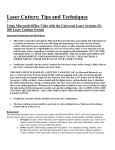
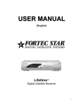
 HPD
D L15
5A7
Eng
gine Insta
allation Manu
M
al
DB-1 and
a DB-6
D 6 Cha
assis
s
8//2010 Swift Chassis DB-1 & DB-6
L15A7 Engine Installation Manual
Table of Contents
1. Safety Consideration and Warnings ..................................................... Page 2
2. Title Page ............................................................................................. Page 3
3. Bell Housing Adapter Preparation ........................................................ Page 4
4. Install Slave Cylinder ............................................................................ Page 6
5. Modify Shifter Rod ................................................................................ Page 8
6. Bell Housing / Oil Tank Preparation ..................................................... Page 9
7. Install Fuel System ............................................................................. Page 10
8. Engine Installation .............................................................................. Page 17
9. Oil System .......................................................................................... Page 20
10. Install Modified Shifter Rod ................................................................ Page 22
11. Miscellaneous ..................................................................................... Page 24
12. Completed Install ................................................................................ Page 25
13. Engine Side Cover Blister Installation. ................................................ Page 27
14. Contact Information ............................................................................. Page 30
1
8/2010
Swift Chassis DB-1 & DB-6
L15A7 Engine Installation Manual
Safety Precautions
The service information in this manual is intended for use by qualified, professional
technicians. Attempting service or repairs without the proper training, tools and
equipment could cause injury or death to you and others. It could also cause damage to
the engine / vehicle or create an unsafe condition.
This manual describes the proper methods and procedures for the race kit installation
related to your chassis, in addition to service and repair procedures described in the
Honda Fit service manual. Some procedures require the use of specifically designed
tools and dedicated equipment. Any person who intends to use a replacement part, a
service procedure, or a tool that is not recommended by Honda or the race sanctioning
body, must determine the risk to their personal safety, and the safe operation of the
vehicle. Any error or oversight while performing this conversion or service can result in
faulty operation, damage to the vehicle, or injury to yourself, or others.
Proper service and maintenance are essential to the racer‟s safety and the reliability of
the race car. If you need to replace any parts, always use the correct parts supplied by
Honda Performance Development or American Honda Motor Co., Inc. Do not use
inferior quality or unapproved parts.
Because this manual is intended for professional technicians, we do not provide
warnings for basic shop safety practices – for example, hot parts = wear gloves. If you
have not received shop safety training or do not feel confident about your knowledge
about safe servicing practices, we recommend that you do not attempt the procedures
described in this manual. We cannot warn you of every conceivable hazard that can
arise in doing service and repair procedures. Only you can decide whether or not you
should do a given task.
Improper service or repairs can create an
unsafe condition that can cause your
customer or others to be seriously hurt or
killed.
Failure to properly follow instructions and
precautions can cause you to be seriously
hurt or killed.
Carefully follow the procedures and
precautions in this manual.
Carefully follow the procedures and
precautions in this manual and other
service material.
2
8/2010
Swift Chassis DB-1 & DB-6
L15A7 Engine Installation Manual
This manual details the steps necessary to install the Honda L15A7 engine
with the HPD engine kit into a Swift DB-1 / DB-6 chassis. The converted
L15A7 engine is designed to be installed utilizing the existing mounting
points of your chassis without modification.
For the purpose of this manual, all photos are of a DB-1 chassis. Specific
parts and procedures unique to the DB-6 are explained when necessary.
3
8/2010
Swift Chassis DB-1 & DB-6
L15A7 Engine Installation Manual
Bell Housing Adapter Preparation
12
10
1.
2.
3
8
3.
3
11
2
7
4.
5.
6.
7.
8.
9.
10.
11.
12.
9
6
10
1
2
Adaptor plate.
Internal hex bolt 3/8-24 x 1-3/4”
(2x)
Internal hex bolt 3/8-24 x 1-1/2”
(2x)
Dowel - 12 x 10mm (2x)
Dowel – 14 x 20mm (2x)
Spherical Bearing (DB-1)
Circlip, Internal – 1.06” (DB-1)
Flange Bolt – 10 x 25mm
Flange Bolt – 10 x 40mm
Flange Bolt – 12 x 60mm (2x)
Flange Bolt – 12 x 65mm
12 x 28mm stud
Polish the circlip groove to remove
the sharp edge.
Circlip Groove.
Heat the adapter plate.
Install the spherical bearing. A light to
moderate press is normal.
Install the internal circlip.
4
8/2010
Swift Chassis DB-1 & DB-6
L15A7 Engine Installation Manual
Bell Housing Adapter Preparation cont’d
Install the locating dowels.
Dowels
Mock up the adapter plate to the
engine.
Note the area where the shifter rod
passes through. This area will need to
be tapered towards the bearing. Mark
the area of the engine block for
material removal. Remove only
enough material to allow the rod to
move freely, leaving enough material
to maintain a mating surface.
5
8/2010
Swift Chassis DB-1 & DB-6
L15A7 Engine Installation Manual
Install Slave Cylinder
For the DB-1
Install the HPD supplied slave
cylinder using the same procedure
used for the Swift slave cylinder.
NOTE: Use new seals and backing
rings.
Install a new release bearing onto the
slave cylinder.
Install the HPD chassis kit input shaft
using the same procedure as the
Swift unit.
Refer to the appropriate manual for
your type of gearbox for proper
installation.
It is suggested that the input shaft
seals be upgraded / replaced at this
time.
6
8/2010
Swift Chassis DB-1 & DB-6
L15A7 Engine Installation Manual
Install Slave Cylinder cont’d
For the DB-6
Remove the release bearing from the
Swift assembly.
Press on the HPD supplied adapter.
Install the new release bearing.
Clutch Slave Cylinder Placement
1. Measure distance from the back of the engine block to the end of the clutch fingers. This is dimension
“A”
2. Place a straight edge across the front of the bell housing and measure from the straight edge to to the
mounting surface of the slave cylinder. This is dimension “B”.
3. With the slave cylinder compressed into the bore, measure the installed height of the slave cylinder.
Add 4.0mm to this dimension for freeplay. This will be dimension “C”.
4. Use the following equation to determine the proper slave cylinder spacer length. B – C – A = XX
Spacer Length.
7
8/2010
Swift Chassis DB-1 & DB-6
L15A7 Engine Installation Manual
Modify Shifter Rod DB-1 Only
The middle shifter rod will need to be
modified to clear the C.V. joint flange.
HPD has supplied the rod for the rear
shifter link.
C.V. Joint Flange
Clearanced Area
The middle Apex joint will need to be
moved forward by 4 inches.
Cut the Apex joint from the rear shifter
rod, and the rear Apex joint of the
middle shifter rod. Weld one joint onto
the new rear rod (gearbox side).
Lay your, and HPD‟s, rod next to each
other and measure the difference in
length (approximately 4 inches). This
will be the amount to remove from the
middle rod.
Cut the middle rod.
Weld the second Apex joint onto the
middle rod.
Drill the bolt hole, being careful to line
up the linkage properly.
NOTE: It is suggested to wait until the
engine and gearbox are properly
installed before drilling the bolt hole.
This will better ensure that the linkage
is clocked properly.
8
8/2010
Swift Chassis DB-1 & DB-6
L15A7 Engine Installation Manual
Bell Housing / Oil Tank Preparation – DB-1 & DB-6
Using Hondalock 2, or its equivalent,
install the AN -10 plug in the upper
left oil return port. This is now an
engine mounting point.
Install oil tank cover using existing
bolts and an RTV-type sealant.
9
8/2010
Swift Chassis DB-1 & DB-6
L15A7 Engine Installation Manual
Install Fuel System – DB-1 & DB-6
The Fit Fuel system consists of the fuel pump, fuel filter, regulator, assorted fittings and hoses.
If you are using your own hose supply, ensure that it is rated for high pressure fuel injection systems. The
HPD-kitted fuel system runs at 50-60 PSI. The feed hose needs to be rated at a minimum of 150 psi.
Remove the regulator from the kit.
Discard the ring, the small O-ring and
the small clip.
Modify the fuel cell cover by using the
drawing provided to add a third outlet.
This will become the fuel out.
The AN-6 center hole (previously the
fuel out) will be for fuel pump harness.
The right side AN-4 will become the
fuel cell vent.
The left side AN-4 is the main fuel
feed out.
10
8/2010
Swift Chassis DB-1 & DB-6
L15A7 Engine Installation Manual
Install Fuel System – DB-1 & DB-6 cont’d
Regulator Housing
Install the regulator into the housing
using a light oil or silicone lubricant on
the O-rings.
Make sure to insert the regulator
square, as it will be easy to cut the
O-rings.
It will take some force by hand to
install the regulator.
Install the clip in the housing.
Pressure Regulator
Position the housing so the return fuel
port faces toward the bottom of the
fuel cell.
Fuel Return Port
Using a pipe thread sealant, install
the AN-4 to 1/8 NPT adaptor into the
housing, on the cover (top) side. This
will connect to the AN-4 bulkhead
feed fitting.
11
8/2010
Swift Chassis DB-1 & DB-6
L15A7 Engine Installation Manual
Install Fuel System – DB-1 & DB-6 cont’d
Using the pipe thread sealant, install
the 5/16‟ Barb to AN-4 ORB adaptor
into the housing, on the fuel cell
(bottom) side. This will connect to the
fuel pump.
NOTE: Be sure the regulator is
sending excess fuel back into the tank
(down) and not into the cover (up).
Install the fuel pump harness into the
AN-6 hole. Ensure the O-ring is in
place.
Snug down the connector.
Loosely install both 90° AN-4
bulkhead fittings in to their respective
positions.
Use the AN-4 crush washers between
the flange and the jam nuts.
12
8/2010
Swift Chassis DB-1 & DB-6
L15A7 Engine Installation Manual
Install Fuel System – DB-1 & DB-6 cont’d
Find the depth of your fuel cell.
Depending on your fuel cell configuration, you may need to remove the two middle sections of fuel cell
foam.
From the top of the cover retainer ring, measure to the bottom of the cell.
Subtract 1/8” – 1/4” from your measurement. This number is the target length for your fuel pump location.
Ensure the fuel pump does not rest on the bottom of the fuel cell.
NOTE: Be sure the cell is not collapsed; you may have to lift up on the retainer ring for an accurate
measurement.
Pressure Regulator Housing
Calculate the length of the
connector hose.
Install the pressure regulator housing
assembly onto the bulkhead fitting in
the cover. Snug the fitting.
Measure from the bottom of the cover
to the bottom of the hose nipple on
the housing, record this number.
Measure the length of the fuel pump
from the bottom of the hose nipple to
the bottom of the pick up screen record this number.
Bulkhead Fitting
Add these two numbers together and
subtract from the overall fuel cell
depth measurement. The final number
will be the length of the connector
hose.
Install the hose with the clamps.
13
8/2010
Swift Chassis DB-1 & DB-6
L15A7 Engine Installation Manual
Install Fuel System – DB-1 & DB-6 cont’d
Clock the fuel pump pick up towards
the rear of the cell.
Clock the regulator housing so fuel is
returned over the pickup.
Tighten all of the connections.
Clock the bulkhead fitting correctly on
the top of the fuel cell cover, so
access to the retainer bolts is possible
and supply and vent hoses are not
overly twisted.
Connect the fuel pump harness to the
pump.
Bulkhead Fittings
Pigtail the harness around the hose
being careful that the harness does
not chafe on the regulator housing.
Harness
You will need to cut out some of the
fuel cell foam from the left side piece.
Only remove enough to be able to
install the cover/pump assembly
easily.
Install the assembly.
14
8/2010
Swift Chassis DB-1 & DB-6
L15A7 Engine Installation Manual
Install Fuel System – DB-1 & DB-6 cont’d
Fuel hose routing
There are 4 cushion clamps supplied
with the kit to mount the fuel filter.
Using the adaptors and reducers
connect the fuel test port to the „out‟
side of the fuel filter.
Mount this assembly using the
cushion clamps about 4-5 inches from
the mid bulkhead (this is only a
suggested location).
Install the 45° push-loc fittings onto
the supplied hose.
Install the fuel feed line onto the fuel
cell cover and route the same as the
original. This will connect to the fuel
filter with another 45° degree pushloc.
Cut the hose to length and install.
15
8/2010
Swift Chassis DB-1 & DB-6
L15A7 Engine Installation Manual
Install Fuel System – DB-1 & DB-6 cont’d
Install the third 45° push-loc onto the
supplied hose.
Connect this to the „vent‟ fitting on the
fuel cell cover, route it the same as
the fuel feed line.
NOTE: You will need to supply your
own vent check valve.
Route the hose as normal.
16
8/2010
Swift Chassis DB-1 & DB-6
L15A7 Engine Installation Manual
Engine Installation
Install the lower rear mounting studs.
This engine will install in the same
manner as your previous engine.
Be sure the water lines are installed
on the engine per the engine race kit
manual.
Install the gearbox adaptor with the
supplied dowels and socket head
bolts to the bell housing.
The spacers in the chassis for the
lower front mounting studs need to be
a minimum length of 30mm, to
prevent the flange nut from bottoming
on the shank of the stud. (1.18”).
Four 3mm thick washers are included
in the kit to help adjust this dimension.
If needed, they are to be placed
between the flange nut and frame
member, indicated by the arrow.
17
8/2010
Swift Chassis DB-1 & DB-6
L15A7 Engine Installation Manual
Engine Installation cont’d
Loosely install the upper front mount.
Be sure the top hat is in the flange on
the head from the bottom.
(From Engine Kit Installation Manual –
Pg 17).
Slide the engine into position; thread
the nuts onto the front studs. Loosely
install the upper mount bolts into the
head.
Apply a small amount of anti-seize to
the splines of the input shaft.
Ensure the lower rear mount studs are
in position and not binding.
Introduce the bell housing assembly
onto the engine.
18
8/2010
Swift Chassis DB-1 & DB-6
L15A7 Engine Installation Manual
Engine Installation cont’d
Align the input shaft splines with the
clutch and mate the bell housing to
the engine.
When you have the dowels engaged,
you can thread in the four bolts and
snug up the bell housing.
Where the bell housing and the
adaptor meet on the underside, it may
be necessary to install shims before
tightening the bottom studs.
Shims are included in the kit (0.01mm
and 0.02mm thickness).
Install the main chassis bolts into the
bell housing. Install the 10mm flange
nut onto the engine stud.
Check the shim dimension on the
bottom of the engine/adaptor plate.
Install the k-nuts onto the studs and
tighten.
Tighten all studs and bolts.
19
8/2010
Swift Chassis DB-1 & DB-6
L15A7 Engine Installation Manual
Oil System
Layout all the hose and fittings before
assembly to understand how the
hoses are to be placed.
NOTE: If you are cutting the braided
hose to length and installing the
fittings yourself be sure you are
familiar with the proper procedures. If
not done correctly you could cause
damage or harm to yourself or others.
The oil feed for both chassis is on the
lower right side of the oil pan. This is
an AN-10 fitting.
There is an in line filter included in the
kit. This should be incorporated into
the oil feed line. Be sure it is installed
in the correct direction.
In-line Filter
The oil return line is a AN-12 at the
bottom of the scavenge pump.
Route the return line up between the
engine and bell housing.
20
8/2010
Swift Chassis DB-1 & DB-6
L15A7 Engine Installation Manual
Oil System cont’d
Route the breather lines, being sure to
check the following items:
1. That the 2mm breather
restrictor is in the valve cover.
2. That the valve cover breather
is not interfering with the
operation of the rear anti roll
bar.
3. That the DB-1 kit has AN-8
hose end fittings and adaptor
fittings for the breather lines.
4. That the DB-6 kit has push loc
fittings for all breather lines.
DB-6 owners may need to grind the
indicated area on the bell housing
adapter to prevent chafing of the oil
feed line.
Area to be clearanced
21
8/2010
Swift Chassis DB-1 & DB-6
L15A7 Engine Installation Manual
Install Modified Shifter Rod
Install the HPD supplied rear shifter
rod.
Install the bolt to the shaft and
selector fork at the gearbox.
Line up the shifter lever in the cockpit
and mark through the middle Apex
joint to place the new bolt hole.
Remove the shaft and drill new bolt
hole.
22
8/2010
Swift Chassis DB-1 & DB-6
L15A7 Engine Installation Manual
Install Modified Shifter Rod cont’d
Install the middle shifter rod; tighten
all bolts securing the shifter rod and
check that you can select all the
gears.
Make fine adjustments at the leverend in the cockpit if necessary.
23
8/2010
Swift Chassis DB-1 & DB-6
L15A7 Engine Installation Manual
Miscellaneous
Install the throttle cable.
Use the method described in the Race
Engine Assembly manual (pg 48) to
set full throttle.
Performance Tip:
Be sure your throttle pedal stop is
strong enough to withstand the force
of your foot.
The pedal should not be able to rock
side-to-side on its pivot point, as this
will lead to premature cable wear and
inconsistent full throttle applications.
Install the exhaust system. Depending
on your previous system you will need
to adjust the height of the tail pipe
support.
Install the Lambda sensor per the
Honda Fit service manual. Plug into
the engine harness.
24
8/2010
Swift Chassis DB-1 & DB-6
L15A7 Engine Installation Manual
Completed Install
Left Side View
Right Side View
25
8/2010
Swift Chassis DB-1 & DB-6
L15A7 Engine Installation Manual
Completed Install cont’d
Top View
Installing fluids:
The oil system will hold the same volume as your previous engine did.
The coolant bleed procedure is the same as your previous engine.
We recommend you prime the oil and fuel systems before starting your L15A7 engine for the first time.
See „Operating Parameters‟ section of your L15A7 Engine Kit Assembly Manual.
NOTE: HPD recommends installing a 19-20psi radiator cap.
Follow the Honda Fit Service manual guidelines for all fluid recommendations.
Connect the brake and clutch lines. Bleed the systems as normal.
26
8/2010
Swift Chassis DB-1 & DB-6
L15A7 Engine Installation Manual
Engine Side Cover Blister Installation
By Stan Clayton
Dauntless Racing Cars, February 2010
Safety Precautions
Personnel undertaking this procedure should read and understand all relevant MSDS documents before
using resins, hardeners, catalysts and solvents, as they can be hazardous to one's health. Use
appropriate safety equipment at all times while working with these materials, with a minimum of long
sleeves, protective gloves, respirator and eye protection.
This set of instructions presumes the reader is familiar with basic composites work. Read and understand
all steps of this procedure before starting it. If you doubt that you can correctly complete the task, do not
hesitate to have an experienced composites shop complete it for you.
Warning
Improper service or repairs can create an
unsafe condition that can cause your
customer or others to be seriously hurt or
killed.
Failure to properly follow instructions and
precautions can cause you to be seriously
hurt or killed.
Follow the procedures and precautions in
this manual carefully.
Follow the procedures and precautions in
this manual and other service materials
carefully.
27
8/2010
Swift Chassis DB-1 & DB-6
L15A7 Engine Installation Manual
Engine Side Cover Blister Installation cont’d
1. The blisters are made approximately one inch oversize to give the installer maximum flexibility to
match the body lines of the engine side covers. Feel free to trim the pieces during installation to
best match your car's side cover body lines. A pneumatic cut-off tool with a 3" x 3/64" narrow kerf
metal cutting wheel works well to make the holes, as well as to trim the blisters. A sanding block,
dremel or die grinder is also handy for making fine adjustments during fitting.
2. Before attempting to match the blister to each side cover, fit the side cover to the chassis with the
Honda Fit engine fully installed and mark the inside of the side cover where the obstruction
strikes it. Remove the side cover from the chassis and carefully cut away a minimum of material
to clear the obstruction. Several fittings may be needed to cut away just enough. Once the hole is
large enough to clear the obstruction, ensure the side cover can be fully installed and uninstalled
without the side cover hitting the obstruction. Measure and record how much clearance is needed
on either side to clear the obstruction.
3. With the trimmed side cover installed on the chassis, place the appropriate blister over the
opening and slide it around on the side cover to best match the side cover body lines, as well as
clear the obstruction. The flanges are left over sized, so the installer may need to trim them to
ensure a good fit. If trimming is needed, go slowly and trim just a little at a time to prevent
trimming too much from the blister. Once the blister is trimmed to best match the body lines, trace
the outline of the trimmed blister on the side cover and set the blister aside.
4. Remove the side cover from the chassis and carefully cut slightly inside the marked outline of the
trimmed blister with the cut-off wheel. Work slowly to ensure you don't remove too much material.
When the hole is roughly cut out inside the line a pneumatic die grinder with a porting stone or
flap wheel works well for final trimming. Or use sand paper held in the hand. Do not use a disc as
it can easily remove too much material. Once satisfied that trimming is complete and that there is
a close fit between the side cover and the blister, set the blister aside and invert the side cover so
that the inner surface (the surface facing the engine) is facing upwards, and support the side
cover on a work bench.
5. Trace a line around the opening approximately 2" outside the trimmed edge of the hole. Scrub the
area with acetone to remove all traces of dirt, grease and oil. It is critical to a successful
installation that all traces of dirt, oil and grease be removed from this area, or the new resin will
not properly adhere. Next, using a sanding block with medium grit paper or a die grinder and flap
wheel, abrade the surface inside the 2" line down to raw resin and/or glass. Remove just enough
material to get clean resin/glass. Don't grind through to the surface! Once the sanding is
complete, vacuum the area to remove the dust. Lightly abrade the inner face of the blister to
ensure a fresh bonding surface.
6. Place the trimmed blister on the fiberglass cloth you will use to make the bonding patch. Trace a
line approximately 1.5" outside the blister's outline and cut the fabric to match the line, then cut
out a matching outline approximately 1.5" inside the outline of the blister. You will now have a
roughly donut shaped piece of fiberglass cloth approximately 3" wide. Repeat the process to
produce two more donuts, approximately 2" wide and 1.5" wide. All three layers can be the full
width, but narrower strips will save a little weight. Three layers should do the job, but you may
add additional layers if you wish, so long as they do not conflict with the chassis tubes or engine
installation. Alternatively, if there is internal clearance, you may wish to use 3 solid patches
covering out to approximately 1.5" outside the blister outline. Cutting out the inside of the patches
(the "donut hole") is not critical...it just saves a little weight.
28
8/2010
Swift Chassis DB-1 & DB-6
L15A7 Engine Installation Manual
Engine Side Cover Blister Installation cont’d
7. It is now time to fit the blister to the side cover and tape the outside with 2" masking tape. Ensure
the entire outside outline of the opening is covered with masking tape, or resin may leak out onto
the outer surface of the side cover. You may also wish to tape the blister in place with additional
pieces of tape running fore and aft and up and down on the outside of the side cover.
8. With the blister securely taped in place (tape ONLY on the OUTSIDE surface!), place the side
cover inner surface up on a soft mount that will support the side cover without distorting it. You
are now ready to bond the blister in place.
9. Ensure the resin and hardener/catalyst and side cover are at or above the minimum working
temperature of the resin. Wear all appropriate safety gear and measure out the resin and
hardener. The blisters are made with epoxy resin, but satisfactory patches can be had with
vinylester or polyester resins, as well. Resin dye may be added to match the color of the patch to
the color of the side cover resin. Resin dyes suitable for all resin types may be purchased at:
Tap Plastics: http://www.tapplastics.com/shop/product.php?pid=50&
10. Once again clean the sanded inner surfaces of the side cover and blister with acetone on a paper
towel and let it dry while mixing the resin and hardener thoroughly. When the acetone is
evaporated and the resin and hardener are thoroughly mixed, brush a light layer of resin over the
sanded and cleaned surfaces, allowing the resin to fill the gap between the side cover and the
blister. Place the widest patching layer carefully in place, distributing it evenly inside and outside
the outline of the blister. Using the brush, gently wet it out with resin and work out any air bubbles
or creases in the fabric so it lies flat to the surface. When the widest layer is wetted out, carefully
place the next smaller layer on top of it and wet that layer out. Alternatively, you may start with
the narrowest layer; it is not critical. Repeat until all layers are in place and wetted out. Allow to
fully cure before proceeding.
11. Once the resin is fully cured (appropriately 24 hours for epoxy, or 12 hours for vinylester or
polyester), carefully remove the masking tape. Using a small sanding block and medium grit
paper, or a dremel or die grinder with a small stone, carefully sand down any resin bubbles that
are standing proud of the outer surface of the side cover.
12. If there are any unsightly transitions between the outer surface of the side cover and the blister,
sand the outer surfaces of the blister and side cover with medium grit paper and apply a thin layer
of body filler to smooth the transitions. Shape and sand the body filler to a smooth line. Repeat
thin layers of body filler as needed to get the desired smooth transition line, then sand and prep
for painting.
13. Prime and paint as desired.
29
8/2010
Swift Chassis DB-1 & DB-6
L15A7 Engine Installation Manual
Contact Information
Honda Performance Development, Inc.
25145 Anza Drive
Santa Clarita, CA. 91355
661-294-7300
Honda Racing Line
[email protected]
Phone: 661-702-7777
Fax: 661-294-7367
30
8/2010