1
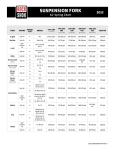
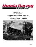
SPECIALIZED BICYCLE OWNER'S MANUAL APPENDIX A SUPPLEMENT 2014 RIDER/BIKE WEIGHT LIMITS AND TERRAIN CONDITIONS 2014 APPENDIX A SUPPLEMENT INTRODUCTION This Appendix A manual supplement is designed as an annual addition to the Appendix A section found in the Specialized Bicycle Owner’s Manual. This appendix is designed to help the rider differentiate between frame structural weight limits and braking distance weight limits. Each bike model is designed and tested to support a structural weight limit, which includes a cargo weight limit. As the weight of the rider approaches the structural weight limit of the bike, the allowable cargo weight might be reduced. For example, a bike may have a 55lb cargo weight limit, but if the weight of the rider is too close to the bike's structural weight limit, the rider may only be allowed to carry a smaller amount of cargo or no cargo at all. See following page for model-specific example and graphs. STRUCTURAL WEIGHT LIMIT CARGO WEIGHT RIDER WEIGHT 0 25 50 75 100 125 150 175 200 225 250 275 300 Additionally, CEN (European Committee for Standardization) has braking distance weight limits, which require that the combined weight of the rider and cargo can be stopped within a specified distance. Exceeding the max weight per CEN braking standards does not mean that the bike will not stop, but that it might not stop within the distance specified by CEN. The following information contains structural weight limits for frames, as well as recommended weight limits based on CEN standards for safe stopping distances. This information will also help determine if the rider and cargo weights are within the weight limits outlined in the Bike Model / Rider Weight Table (pages 5-6). UNDERSTANDING WEIGHT LIMITS FRAME STRUCTURAL WEIGHT LIMITS Structural weight limits for each bike are determined by Specialized Bicycles through extensive lab testing, and are listed in the Bike Model / Rider Weight Table. STRUCTURAL WEIGHT LIMIT: The maximum weight (rider and cargo) a bike can physically support. This limit is different from the MAX WEIGHT PER CEN BRAKING STANDARDS (see below). RIDER WEIGHT: The weight of the rider in riding gear (e.g., jacket, helmet cam, hydration pack, helmet, etc.). CARGO WEIGHT: The weight of any additional accessories (e.g., panniers, rear racks, saddle bags, handlebar bags, baskets, etc.) not accounted for in Rider Weight. CARGO WEIGHT LIMIT: The maximum cargo weight a bike has been tested to support structurally. TOTAL WEIGHT: The sum of Rider Weight and Cargo Weight. MAX WEIGHT PER CEN BRAKING STANDARDS Each bike model is tested to determine the maximum amount of weight (combined weight of Rider and Cargo) that can be applied to a bike and the capability to stop the bike within a prescribed distance. In situations where the weight limit for CEN braking standards does not exceed the structural weight limit, the maximum allowable weight limit is determined by the braking limit. In all other cases, the maximum allowable weight limit is determined by the structural weight limit. 1 DETERMINING MAXIMUM ALLOWABLE WEIGHT LIMITS 1. Find your bike in the Bike Model / Rider Weight Table. 2. Lookup the cargo weight limit and the Maximum Allowable Weight Limit of the bike model. 3. Determine the rider weight, which includes all riding gear. 4. Determine the cargo weight, which includes the weight of any additional accessories. 5. .Substract the rider weight from the recommended max weight. The result is the amount the rider is allowed for cargo weight, up to the cargo weight limit prescribed for the bike model. EXAMPLE: HARDROCK (Maximum Allowable Weight Limit = 300lb / 136kg. Cargo Weight Limit = 55lb / 25kg) STRUCTURAL WEIGHT LIMIT CARGO WEIGHT RIDER WEIGHT 0 25 50 75 100 125 150 175 200 225 250 275 300 Rider (255lb) + cargo (20lb) =275lb Total weight ok STRUCTURAL WEIGHT LIMIT CARGO WEIGHT RIDER WEIGHT 0 25 50 75 100 125 Rider (245lb) + cargo (55lb) = 300lb Total weight ok 150 175 200 225 250 275 300 STRUCTURAL WEIGHT LIMIT CARGO WEIGHT RIDER WEIGHT 0 25 50 75 100 125 150 175 200 225 250 275 290 300 275 300 Rider (290lb) + cargo (10lb) =300lb Total weight ok RIDE AT STRUCTURAL WEIGHT LIMIT CARGO WEIGHT RIDER WEIGHT 0 25 50 75 100 125 150 175 210 200 225 250 OWN RISK Rider (210lb) + cargo (65lb) = 275lb Total too heavy. Cargo weight exceeds cargo weight limit and has to be reduced. RIDE AT STRUCTURAL WEIGHT LIMIT CARGO WEIGHT RIDER WEIGHT 0 OWN RISK 25 50 75 100 125 150 175 200 225 250 275 310 300 225 250 275 310 300 Rider (255lb) + cargo (55lb) = (310lb) Total too heavy. Rider and/or cargo weight has to be reduced. RIDE AT STRUCTURAL WEIGHT LIMIT RIDER WEIGHT 0 OWN RISK 2 25 50 75 100 125 Rider (310lb) + no cargo = 310lb Rider weight exceed structural weight limit 150 175 200 INTENDED USE OF YOUR BICYCLE WARNING: Understand your bike and its intended use. Choosing the wrong bicycle for your purpose can be hazardous. Using your bike the wrong way is dangerous. No single type of bicycle is suited for all purposes. Your retailer can help you pick the “right tool for the job” and help you understand its limitations. There are many types of bicycles and many variations within each type. There are many types of mountain, road, racing, hybrid, touring, cyclocross and tandem bicycles. There are also bicycles that mix features. For example, there are road/racing bikes with triple cranks. These bikes have the low gearing of a touring bike, the quick handling of a racing bike, but are not well suited for carrying heavy loads on a tour, for which, you want a touring bike. Within each of type of bicycle, one can optimize the bicycle for certain purposes. Visit your bicycle shop and find someone with expertise in the area that interests you. Do your own homework. Seemingly small changes such as the choice of tires can improve or diminish the performance of a bicycle for a certain purpose. On the following pages, we generally outline the intended uses of all bike types and, based in part on max weight per CEN braking standards, we specify the maximum rider weights by bike family/model. Industry usage conditions are generalized and evolving. Consult your dealer about how you intend to use your bike. HIGH-PERFORMANCE ROAD 9ED:?J?ED'0Bikes designed for riding on a paved surface where the tires do not lose ground contact. ?DJ;D:;:0To be ridden on paved roads only. DEJ?DJ;D:;:0For off-road, cyclocross, or touring with racks or panniers. JH7:;E<<0Material use is optimized to deliver both light weight and specific performance. You must understand that (1) these types of bikes are intended to give an aggressive racer or competitive cyclist a performance advantage over a relatively short product life, (2) a less aggressive rider will enjoy longer frame life, (3) you are choosing light weight (shorter frame life) over more frame weight and a longer frame life, (4) you are choosing light weight over more dent resistant or rugged frames that weigh more. All frames that are very light need frequent inspection. These frames are likely to be damaged or broken in a crash. They are not designed to take abuse or be a rugged workhorse. See also Appendix B. GENERAL PURPOSE RIDING 9ED:?J?ED(0Bikes designed for riding Condition 1, plus smooth gravel roads and improved trails with moderate grades where the tires do not lose ground contact. ?DJ;D:;:0For paved roads, gravel or dirt roads that are in good condition, and bike paths. DEJ?DJ;D:;:0For off-road or mountain bike use, or for any kind of jumping. Some of these bikes have suspension features, but these features are designed to add comfort, not off-road capability. Some come with relatively wide tires that are well suited to gravel or dirt paths. Some come with relatively narrow tires that are best suited to faster riding on pavement. If you ride on gravel or dirt paths, carry heavier loads or want more tire durability talk to your dealer about wider tires. CYCLO-CROSS 9ED:?J?ED(0Bikes designed for riding Condition 1, plus smooth gravel roads and improved trails with moderate grades where the tires do not lose ground contact. ?DJ;D:;:0For cyclo-cross riding, training and racing. Cyclo-cross involves riding on a variety of terrain and surfaces including dirt or mud surfaces. Cyclo-cross bikes also work well for all weather rough road riding and commuting. DEJ?DJ;D:;:0For off road or mountain bike use, or jumping. Cyclo-cross riders and racers dismount before reaching an obstacle, carry their bike over the obstacle and then remount. Cyclo-cross bikes are not intended for mountain bike use. The relatively large road bike size wheels are faster than the smaller mountain bike wheels, but are not as strong. CROSS-COUNTRY, MARATHON, HARDTAILS 9ED:?J?ED)0Bikes designed for riding Conditions 1 and 2, plus rough trails, small obstacles, and smooth technical areas, including areas where momentary loss of tire contact with the ground may occur. NOT for jumping. All mountain bikes without rear suspension are Condition 3, as well as some lightweight rear suspension models. ?DJ;D:;:0For cross-country riding and racing which ranges from mild to aggressive over intermediate terrain (e.g., hilly with small obstacles like roots, rocks, loose surfaces, hard pack and depressions). Cross-country and marathon equipment (tires, shocks, frames, drive trains) are light-weight, favoring nimble speed over brute force. Suspension travel is relatively short since the bike is intended to move quickly on the ground. DEJ?DJ;D:;:0For Hardcore Freeriding, Extreme Downhill, Dirt Jumping, Slopestyle, or very aggressive or extreme riding. Not for spending time in the air, landing hard and hammering through obstacles. JH7:;E<<0Cross-Country bikes are lighter, faster to ride uphill, and more nimble than All-Mountain bikes. Cross-Country and Marathon bikes trade off some ruggedness for pedaling efficiency and uphill speed. 3 ALL MOUNTAIN 9ED:?J?ED*0Bikes designed for riding Conditions 1, 2, and 3, plus rough technical areas, moderately sized obstacles, and small jumps. ?DJ;D:;:0For trail and uphill riding. All-Mountain bicycles are: (1) more heavy duty than cross country bikes, but less heavy duty than Freeride bikes, (2) lighter and more nimble than Freeride bikes, (3) heavier and have more suspension travel than a cross country bike, allowing them to be ridden in more difficult terrain, over larger obstacles and moderate jumps, (4) intermediate in suspension travel and use components that fit the intermediate intended use, (5) cover a fairly wide range of intended use, with models that are more or less heavy duty. Talk to your retailer about your needs and these models. DEJ?DJ;D:;:0For use in extreme forms of jumping/riding such as hardcore mountain, Freeriding, Downhill, North Shore, Dirt Jumping, Hucking etc. Not for large drop offs, jumps or launches (wooden structures, dirt embankments) requiring long suspension travel or heavy duty components; and not for spending time in the air landing hard and hammering through obstacles. JH7:;E<<0All-Mountain bikes are more rugged than cross country bikes, for riding more difficult terrain. All-Mountain bikes are heavier and harder to ride uphill than cross country bikes. All-Mountain bikes are lighter, more nimble and easier to ride uphill than Freeride bikes. All-Mountain bikes are not as rugged as Freeride bikes and must not be used for more extreme riding and terrain. GRAVITY, FREERIDE AND DOWNHILL 9ED:?J?ED+0Bikes designed for jumping, hucking, high speeds, or aggressive riding on rougher surfaces, or landing on flat surfaces. However, this type of riding is extremely hazardous and puts unpredictable forces on a bicycle which may overload the frame, fork, or parts. If you choose to ride in Condition 5 terrain, you should take appropriate safety precautions such as more frequent bike inspections and replacement of equipment. You should also wear comprehensive safety equipment such as a full-face helmet, pads, and body armor. ?DJ;D:;:0For riding that includes the most difficult terrain that only very skilled riders should attempt. Gravity, Freeride, and Downhill are terms which describe hardcore mountain, north shore, slopestyle. This is “extreme” riding and the terms describing it are constantly evolving. Gravity, Freeride, and Downhill bikes are: (1) heavier and have more suspension travel than All-Mountain bikes, allowing them to be ridden in more difficult terrain, over larger obstacles and larger jumps, (2) the longest in suspension travel and use components that fit heavy duty intended use. There is no guarantee that extreme riding will not break a Freeride bike. The terrain and type of riding that Freeride bikes are designed for is inherently dangerous. Appropriate equipment, such as a Freeride bike, does not change this reality. In this kind of riding, bad judgment, bad luck, or riding beyond your capabilities can easily result in an accident, where you could be seriously injured, paralyzed or killed. DEJ?DJ;D:;:0To be an excuse to try anything. Read Section 2. F of the Bicycle Owner’s Manual, p. 12. JH7:;E<<0Freeride bikes are more rugged than All-Mountain bikes, for riding more difficult terrain. Freeride bikes are heavier and harder to ride uphill than All-Mountain bikes. DIRT JUMP 9ED:?J?ED+0Bikes designed for jumping, hucking, high speeds, or aggressive riding on rougher surfaces, or landing on flat surfaces. However, this type of riding is extremely hazardous and puts unpredictable forces on a bicycle which may overload the frame, fork, or parts. If you choose to ride in Condition 5 terrain, you should take appropriate safety precautions such as more frequent bike inspections and replacement of equipment. You should also wear comprehensive safety equipment such as a full-face helmet, pads, and body armor. ?DJ;D:;:0For man-made dirt jumps, ramps, skate parks other predictable obstacles and terrain where riders need and use skill and bike control, rather than suspension. Dirt Jumping bikes are used much like heavy duty BMX bikes. A Dirt Jumping bike does not give you skills to jump. Read Section 2. F of the Bicycle Owner’s Manual, p. 12. DEJ?DJ;D:;:0For terrain, drop offs or landings where large amounts of suspension travel are needed to help absorb the shock of landing and help maintain control. JH7:;E<<0Dirt Jumping bikes are lighter and more nimble than Freeride bikes, but they have no rear suspension and the suspension travel in the front is much shorter. KIDS Bikes designed to be ridden by children. Parental supervision is required at all times. Avoid areas involving automobiles, and obstacles or hazards including inclines, curbs, stairs, sewer grates or areas near drop-offs or pools. The Hotwalk Owner's Manual is available as a separate document, supplied with the Hotwalk bikes 4 BIKE MODEL / RIDER WEIGHT TABLE MAXIMUM CARGO WEIGHT MAXIMUM ALLOWABLE WEIGHT 4, 5 CATEGORY (See Intended Use Page 3) Alias All Models 1 5 / 2.3 1 240 / 109 3 S-Works 1 30 / 14 2 240 / 109 3 Expert, Race, Elite INT, Sport INT, Comp 1 30 / 14 2 275 / 125 Elite, Sport, Base * 1 30 / 14 2 220 / 100 3 * Sport, Sora * 1 5 / 2.3 220 / 100 3 * S-Works, Pro, Expert, Comp 1 5 / 2.3 1 240 / 109 3 Ariel All Models 2 55 / 25 300 / 136 AWOL AWOL Rare 2 55 / 25 300 / 136 S-Works, Expert 4 5 / 2.3 240 / 109 3 Comp Carbon 4 5 / 2.3 1 275 / 125 1 300 / 136 Allez Amira Camber FSR 1 1 EVO, Comp, Base 4 5 / 2.3 Crave All Models 3 30 / 14 2 300 / 136 Crossover All Models 2 55 / 25 300 / 136 Crossroads All Models 2 55 / 25 300 / 136 CrossTrail All Models 2 55 / 25 300 / 136 S-Works, Pro, Expert, Elite 2 5 / 2.3 240 / 109 3 Sport Carbon 105 2 5 / 2.3 1 275 / 125 Sport Apex Disc 2 30 / 14 2 275 / 125 Sora * 2 30 / 14 All Models * 2 55 / 25 220 / 100 3 * S-Works 5 5 / 2.3 240 / 109 3 I, II 5 5 / 2.3 1 300 / 136 I Carbon 5 5 / 2.3 1 275 / 125 Comp INT, Elite INT, Sport INT (Shimano Brakes) 1 55 / 25 275 / 125 Comp, Elite, Sport, Base * 1 55 / 25 220 / 100 3 * S-Works, Expert Carbon 4 5 / 2.3 1 240 / 109 3 Expert EVO, Comp, EVO 4 5 / 2.3 1 300 / 136 S-Works, Marathon Carbon, Expert Carbon 3 5 / 2.3 1 240 / 109 3 Comp Carbon 3 5 / 2.3 1 275 / 125 Comp 3 5 / 2.3 1 300 / 136 Base, all models 2 55 / 25 300 / 136 Step Through, all models 2 55 / 25 240 / 109 Fatboy All Models 3 55 / 25 275 / 125 Fate All Models 3 5 / 2.3 1 240 / 109 3 Hardrock All Models 3 55 / 25 300 / 136 24" XC Models 3 55 / 25 220 / 100 24" 21spd, 7spd, street; 20" 6spd, Coaster 6 30 / 14 2 220 / 100 16" and 12" Coasters 6 30 / 14 CruX Daily Demo FSR Dolce Enduro FSR Epic FSR Expedition Hotrock Jett Langster 1 2 1 2 220 / 100 3 * 100 / 45 Hotwalk boy/girl 6 0/0 40 / 18 All Models 3 55 / 25 300 / 136 Pro 1 30 / 14 2 240 / 109 3 Base * 1 30 / 14 2 265/120 3 * Street * 1 30 / 14 220 / 100 3 * 2 5 BIKE MODEL / RIDER WEIGHT TABLE MAXIMUM CARGO WEIGHT MAXIMUM ALLOWABLE WEIGHT 4, 5 CATEGORY (See Intended Use Page 3) Myka HT All Models 3 55 / 25 300 / 136 P.Slope, P.3, P.26 AM, P.Street 5 0/0 300 / 136 P.20, P.18, P.Grom 5 0/0 220 / 100 Rockhopper All Models 3 55 / 25 300 / 136 Roll All Models * 1 30 / 14 2 220 / 100 3 * Roubaix All Models 1 5 / 2.3 1 240 / 109 3 Ruby All Models 1 5 / 2.3 1 240 / 109 3 Rumor FSR All Models 4 5 / 2.3 240 / 109 3 Safire FSR All Models 3 5 / 2.3 1 300 / 136 Expert 1 55 / 25 240 / 109 3 Comp, Elite, Sport INT, Sport Disc 1 55 / 25 275 / 125 Base, X3, Sport * 1 55 / 25 220 / 100 3 * All Models * 1 5 / 2.3 1 220 / 100 3 * Pro, SL4, Expert 1 55 / 25 240 / 109 3 Comp Disc, Elite Disc, Elite INT, Sport, Sport Disc 2 55 / 25 300 / 136 Comp, Comp Carbon, Elite, Base * 2 55 / 25 265 / 120 3 * S-Works, Expert Carbon, Elite 4 5 / 2.3 240 / 109 3 Comp Carbon 4 5 / 2.3 1 275 / 125 Comp 4 5 / 2.3 1 300 / 136 S-Works, Marathon, Expert, Carbon SS 3 5 / 2.3 1 240 / 109 3 SJ HT Comp Carbon 3 5 / 2.3 1 275 / 125 Comp, EVO 3 30 / 14 2 300 / 136 P.Series Secteur Shiv Sirrus SJ FSR SJ HT 1 1 LTD Disc, Pro Disc 2 55 / 25 275 / 125 Source Eleven, Expert, Comp, Eight, Elite, Seven, Sport, Base 2 55 / 25 300 / 136 Status FSR All Models 5 30 / 14 2 300 / 136 Tarmac All Models 1 5 / 2.3 240 / 109 3 Transition All Models * 1 5 / 2.3 1 220 / 100 3 * Comp Disc 1 55 / 25 240 / 109 3 Elite Disc, Sport Disc 1 55 / 25 275 / 125 Base * 1 55 / 25 220 / 100 3 * Turbo All Models 2 55 / 25 300 / 136 Venge All Models 1 5 / 2.3 1 240 / 109 3 Pro Carbon 1 5 / 2.3 1 240 / 109 3 Expert Carbon 2 5 / 2.3 1 275 / 125 Comp Carbon * 2 5 / 2.3 1 220 / 100 3 * Comp, Base Sport * 2 55 / 25 265 / 120 3 * Elite, Sport Disc 2 55 / 25 300 / 136 All Models * 2 55 / 25 271 / 124 3 * TriCross Vita Work See following page for footnotes 6 1 FOOTNOTES 1 Seat Bag Only. 2 For ALLOY bikes manufactured without original equipment dropout rack mounts: A rear rack can be installed with the use of separate rack mount clips. Cargo capacity with separate mounting clips is limited to 30lb / 14kg. 3 STRUCTURAL WEIGHT LIMITS FOR FRAMES: 275lb / 125Kg 300lb / 126Kg Drop bar equipped carbon or alloy road bikes Alloy mountain bikes Carbon or alloy cyclocross bikes Flat bar equipped alloy hybrid / city bikes Carbon or alloy triathlon / aero / time trial bikes Flat bar equipped carbon hybrid / city bikes Carbon mountain bikes If any weight-bearing Specialized-branded carbon components (i.e. handlebar, seatpost, stem, crank, saddle, rim) are present, then the weight limit is 240lb / 109kg. This does not include non-weight-bearing carbon components such as brake levers, chainrings, bottle cages, etc. Roval wheels (complete wheelsets) are made to be lightweight, and are not suitable for all riders and all possible uses. If any Roval wheelsets are present, the rider (plus cargo) weight limit is 240lb (109Kg). Failure to follow this warning may result in a catastrophic failure of the wheel. * MODELS: The Maximum Allowable Weight Limit for these models are determined by CEN standards for stopping distance. The Structural Weight Limit for a particular model can exceed this maximum limit for stopping distance (see STRUCTURAL WEIGHT LIMITS FOR FRAMES, above). If a rider's weight is above the Maximum Allowable Weight Limit but below the Structural Weight Limit, the rider would be able to use the bike from a structural standpoint, but with reduced braking that does not conform to CEN requirements. IMPORTANT: Braking limits do not change regardless of carbon or alloy components. 4 Recommended max weights are based on European (CEN) testing standards (for cargo and rider only). 5 CEN braking standards are based on the brakes specified on the bike models from the manufacturer. Changing the brakes can result in an increase or decrease in the braking distance. WARNING: For riders at the RIDER WEIGHT LIMIT, you may not be able to carry cargo if the TOTAL WEIGHT LIMIT is exceeded. SPECIALIZED BICYCLE COMPONENTS 15130 Concord Circle, Morgan Hill, CA 95037 (408) 779-6229 0000037057_OM_EN R2, 09/13 Please note all instructions are subject to change and updates without notice. Please visit www.specialized.com for periodic tech updates. Feedback: [email protected] 7 2014 SUSPENSION FORK OIL, AIR, AND COIL CHARTS GEN.0000000004392 Rev A © 2013 SRAM LLC RockShox Oil Volume Chart 30 Gold Fork Drive Side Model Damper Technology TK Volume (mL) Lower Leg Oil wt Volume (mL) Oil wt 5 5 15 Turnkey TK 27 TK 29 143 3-8 BoXXer Domain Lyrik Oil wt - Solo Air Volume (mL) Oil wt 10 15 3-8 Solo Air 5 RC 130 15 10 - Motion Control DH 30 Solo Air with Volume Adjust 10 230 5 R2C2 10 15 Coil with Drop Stop RC Motion Control IS 290 Coil Dual Crown RC Motion Control IS 325 Coil Dual Crown R Rebound 370 RC 15 Coil Rebound 5 10 15 - 15 40 40 Coil U-Turn Coil - 15 30 Motion Control Coil U-Turn Coil 200 Pike Volume (mL) Lower Leg 105 World Cup Reba Upper Tube Motion Control R Recon Gold Spring Technology 85 RCT Argyle Upper Tube Non-Drive Side R Rebound RC2L RC2DH Mission Control Mission Control DH 184 RC Motion Control IS 187 R Rebound 213 Charger Bleed Dual Position Air Solo Air 5 10 15 - 10 15 Solo Air Coil RCT3 3 5 0w30 Solo Air - 15 0w30 5 5 15 Solo Air Grease 5 15 6 15 RC RLT, RL 106 Motion Control RL3 TK TK29 RL R 111 Turnkey Rebound Motion Control Solo Air 133 5 6 3 15 15 Coil - 10 2 RockShox Oil Volume Chart Recon Silver Model TK Revelation Fork Drive Side WC XXWC XX RCT3 RLT RL Damper Technology SID Volume (mL) Oil wt Lower Leg Volume (mL) Turnkey Oil wt 150 5 6 15 Motion Control WC XXWC XX RCT3 RLT RL 134 Volume (mL) Oil wt 6 - 15 12 Dual Position Air Solo Air Grease 5 15 5 5 15 Solo Air Grease 5 15 3-8 15 10-16 15 12 15 98 Motion Control 106 111 120 U-Turn 130 5 5-8 - 15 U-Turn 140 125 U-Turn 150 Sektor Silver 125 5 6 15 XC 32 Motion Control Turnkey Solo Air 150 TK Turnkey 150 5 6 15 Solo Air - 6 Solo Air - 15 12 Coil 100 TK Turnkey 122 5 5 15 Solo Air Coil - 5 10 15 Coil - 10 15 123 TK 27 93 80/100 Turnkey 120 Oil wt 15 Turnkey TK 29 Volume (mL) 5 130 RL TK Lower Leg 5 TK XC 30 Upper Tube Coil RLT3 RL3 XC 28 Spring Technology Solo Air WC 1 1/8 XXWC 1 1/8 Sektor Gold Upper Tube Non-Drive Side - 109 3 RockShox Air Spring Pressures by Rider Weight <140 LBS 140-160 LBS 160-180 LBS 180-200 LBS 200-220 LBS (<63 KG) (63-72 KG) (72-81 KG) (81-90 KG) (90-99 KG) 90-110 psi 110-125 psi 125-140 psi 140-160 psi 175+ psi 265 psi 50-70 psi 70-85 psi 85-100 psi 100-120 psi 135+ psi 205 psi Argyle 120-135 psi 135-150 psi 150-165 psi 165-180 psi 180+ psi 220 psi BoXXer 30-45 psi 45-60 psi 60-75 psi 75-90 psi 90-105 psi 165 psi Lyrik 45-55 psi 55-65 psi 65-75 psi 75-85 psi 85-95 psi 148 psi Lyrik 45-65 psi 65-85 psi 85-105 psi 105-125 psi 125-145 psi 248 psi Pike 45-55 psi 55-65 psi 65-75 psi 75-85 psi 85-95 psi 148 psi Pike 29 55-65 psi 65-75 psi 75-85 psi 85-95 psi 95-105 psi 163 psi 45-65 psi 65-85 psi 85-105 psi 105-125 psi 125-145 psi 248 psi Reba 70-90 psi 90-105 psi 105-120 psi 120-135 psi 135+ psi 200 psi Recon Gold 90-110 psi 110-125 psi 125-140 psi 140-160 psi 175+ psi 265 psi 50-70 psi 70-85 psi 85-100 psi 100-120 psi 135+ psi 205 psi 90-110 psi 110-125 psi 125-140 psi 140-160 psi 175+ psi 265 psi 50-70 psi 70-85 psi 85-100 psi 100-120 psi 135+ psi 205 psi Revelation 65-85 psi 75-100 psi 85-115 psi 95-125 psi 125+ psi 220 psi Revelation <110 psi 110-125 psi 125-140 psi 140-155 psi 155-170 psi 255 psi Sektor Gold 40-60 psi 60-75 psi 75-90 psi 90-105 psi 105+ psi 225 psi Sektor Silver 50-70 psi 70-85 psi 85-100 psi 100-120 psi 120+ psi 200 psi SID 70-90 psi 90-105 psi 105-120 psi 120-135 psi 135+ psi 200 psi XC32 90-110 psi 110-125 psi 125-140 psi 140-160 psi 175+ psi 265 psi 50-70 psi 70-85 psi 85-100 psi 100-120 psi 135+ psi 205 psi 90-110 psi 110-125 psi 125-140 psi 140-160 psi 175+ psi 265 psi 50-70 psi 70-85 psi 85-100 psi 100-120 psi 135+ psi 205 psi FORK 30 Gold 80 mm 30 Gold 100-120 mm Dual Position Air 120-140 mm Pike Dual Position Air 80 mm Recon Gold 100-120 mm Recon Silver 80 mm Recon Silver 100-120 mm Dual Position Air 80 mm XC32 100-120 mm XC30 80 mm XC30 100-120 mm MAX PSI 4 RockShox Coil Springs by Rider Weight FORK Argyle <140 LBS 140-160 LBS 160-180 LBS 180-200 LBS 200-220 LBS (<63 KG) (63-72 KG) (72-81 KG) (81-90 KG) (90-99 KG) Red Medium Blue Firm Black X-Firm Not Available Pink XXX-Firm Silver X-Soft Yellow Firm Red Medium Blue Firm Black X-Firm Silver X-Soft Yellow Firm Red Medium Blue Firm Black X-Firm Green X-Soft Black Soft Yellow Medium Red Firm Blue X-Firm Silver X-Soft Yellow Firm Red Medium Blue Firm Black X-Firm BoXXer Domain Lyrik Recon Silver Recon Gold Sektor XC 28 80 / 100 mm XC 28 120 mm XC30 XC32 5 2014 SUSPENSION FORK OIL, AIR, AND COIL CHARTS !"#$%%%%%%%%%&'()*+,-*.* /*)%0'*1+.2*334 RockShox Oil Volume Chart 30 Gold Fork Drive Side Model Damper Technology TK Volume (mL) Lower Leg Oil wt Volume (mL) Oil wt 5 5 15 Turnkey TK 27 TK 29 143 3-8 BoXXer Domain Lyrik Oil wt - Solo Air Volume (mL) Oil wt 10 15 3-8 Solo Air 5 RC 130 15 10 - Motion Control DH 30 Solo Air with Volume Adjust 10 230 5 R2C2 10 15 Coil with Drop Stop RC Motion Control IS 290 Coil Dual Crown RC Motion Control IS 325 Coil Dual Crown R Rebound 370 RC 15 Coil Rebound 5 10 15 - 15 40 40 Coil U-Turn Coil - 15 30 Motion Control Coil U-Turn Coil 200 Pike Volume (mL) Lower Leg 105 World Cup Reba Upper Tube Motion Control R Recon Gold Spring Technology 85 RCT Argyle Upper Tube Non-Drive Side R Rebound RC2L RC2DH Mission Control Mission Control DH 184 RC Motion Control IS 187 R Rebound 213 Charger Bleed Dual Position Air Solo Air 5 10 15 - 10 15 Solo Air Coil RCT3 3 5 0w30 Solo Air - 15 0w30 5 5 15 Solo Air Grease 5 15 6 15 RC RLT, RL 106 Motion Control RL3 TK TK29 RL R 111 Turnkey Rebound Motion Control Solo Air 133 5 6 3 15 15 Coil - 10 2 RockShox Oil Volume Chart Recon Silver Model TK Revelation Fork Drive Side WC XXWC XX RCT3 RLT RL Damper Technology SID Volume (mL) Oil wt Lower Leg Volume (mL) Turnkey Oil wt 150 5 6 15 Motion Control WC XXWC XX RCT3 RLT RL 134 Volume (mL) Oil wt 6 - 15 12 Dual Position Air Solo Air Grease 5 15 5 5 15 Solo Air Grease 5 15 3-8 15 10-16 15 12 15 98 Motion Control 106 111 120 U-Turn 130 5 5-8 - 15 U-Turn 140 125 U-Turn 150 Sektor Silver 125 5 6 15 XC 32 Motion Control Turnkey Solo Air 150 TK Turnkey 150 5 6 15 Solo Air - 6 Solo Air - 15 12 Coil 100 TK Turnkey 122 5 5 15 Solo Air Coil - 5 10 15 Coil - 10 15 123 TK 27 93 80/100 Turnkey 120 Oil wt 15 Turnkey TK 29 Volume (mL) 5 130 RL TK Lower Leg 5 TK XC 30 Upper Tube Coil RLT3 RL3 XC 28 Spring Technology Solo Air WC 1 1/8 XXWC 1 1/8 Sektor Gold Upper Tube Non-Drive Side - 109 3 RockShox Air Spring Pressures by Rider Weight <140 LBS 140-160 LBS 160-180 LBS 180-200 LBS 200-220 LBS (<63 KG) (63-72 KG) (72-81 KG) (81-90 KG) (90-99 KG) 90-110 psi 110-125 psi 125-140 psi 140-160 psi 175+ psi 265 psi 50-70 psi 70-85 psi 85-100 psi 100-120 psi 135+ psi 205 psi Argyle 120-135 psi 135-150 psi 150-165 psi 165-180 psi 180+ psi 220 psi BoXXer 30-45 psi 45-60 psi 60-75 psi 75-90 psi 90-105 psi 165 psi Lyrik 45-55 psi 55-65 psi 65-75 psi 75-85 psi 85-95 psi 148 psi Lyrik 45-65 psi 65-85 psi 85-105 psi 105-125 psi 125-145 psi 248 psi Pike 45-55 psi 55-65 psi 65-75 psi 75-85 psi 85-95 psi 148 psi Pike 29 55-65 psi 65-75 psi 75-85 psi 85-95 psi 95-105 psi 163 psi 45-65 psi 65-85 psi 85-105 psi 105-125 psi 125-145 psi 248 psi Reba 70-90 psi 90-105 psi 105-120 psi 120-135 psi 135+ psi 200 psi Recon Gold 90-110 psi 110-125 psi 125-140 psi 140-160 psi 175+ psi 265 psi 50-70 psi 70-85 psi 85-100 psi 100-120 psi 135+ psi 205 psi 90-110 psi 110-125 psi 125-140 psi 140-160 psi 175+ psi 265 psi 50-70 psi 70-85 psi 85-100 psi 100-120 psi 135+ psi 205 psi Revelation 65-85 psi 75-100 psi 85-115 psi 95-125 psi 125+ psi 220 psi Revelation <110 psi 110-125 psi 125-140 psi 140-155 psi 155-170 psi 255 psi Sektor Gold 40-60 psi 60-75 psi 75-90 psi 90-105 psi 105+ psi 225 psi Sektor Silver 50-70 psi 70-85 psi 85-100 psi 100-120 psi 120+ psi 200 psi SID 70-90 psi 90-105 psi 105-120 psi 120-135 psi 135+ psi 200 psi XC32 90-110 psi 110-125 psi 125-140 psi 140-160 psi 175+ psi 265 psi 50-70 psi 70-85 psi 85-100 psi 100-120 psi 135+ psi 205 psi 90-110 psi 110-125 psi 125-140 psi 140-160 psi 175+ psi 265 psi 50-70 psi 70-85 psi 85-100 psi 100-120 psi 135+ psi 205 psi FORK 30 Gold 80 mm 30 Gold 100-120 mm Dual Position Air 120-140 mm Pike Dual Position Air 80 mm Recon Gold 100-120 mm Recon Silver 80 mm Recon Silver 100-120 mm Dual Position Air 80 mm XC32 100-120 mm XC30 80 mm XC30 100-120 mm MAX PSI 4 RockShox Coil Springs by Rider Weight FORK Argyle <140 LBS 140-160 LBS 160-180 LBS 180-200 LBS 200-220 LBS (<63 KG) (63-72 KG) (72-81 KG) (81-90 KG) (90-99 KG) Red Medium Blue Firm Black X-Firm Not Available Pink XXX-Firm Silver X-Soft Yellow Firm Red Medium Blue Firm Black X-Firm Silver X-Soft Yellow Firm Red Medium Blue Firm Black X-Firm Green X-Soft Black Soft Yellow Medium Red Firm Blue X-Firm Silver X-Soft Yellow Firm Red Medium Blue Firm Black X-Firm BoXXer Domain Lyrik Recon Silver Recon Gold Sektor XC 28 80 / 100 mm XC 28 120 mm XC30 XC32 5 2013 Reba Service Manual GEN.0000000004216 Rev A © 2012 SRAM LLC SRAM LLC WARRANTY EXTENT OF LIMITED WARRANTY Except as otherwise set forth herein, SRAM warrants its products to be free from defects in materials or workmanship for a period of two years after original purchase. This warranty only applies to the original owner and is not transferable. Claims under this warranty must be made through the retailer where the bicycle or the SRAM component was purchased. Original proof of purchase is required. Except as described herein, SRAM makes no other warranties, guaranties, or representations of any type (express or implied), and all warranties (including any implied warranties of reasonable care, merchantibility, or fitness for a particular purpose) are hereby disclaimed. LOCAL LAW 7KLVZDUUDQW\VWDWHPHQWJLYHVWKHFXVWRPHUVSHFL¿FOHJDOULJKWV7KHFXVWRPHUPD\DOVRKDYHRWKHUULJKWVZKLFKYDU\IURPVWDWHWRVWDWH86$IURP SURYLQFHWRSURYLQFH&DQDGDDQGIURPFRXQWU\WRFRXQWU\HOVHZKHUHLQWKHZRUOG 7RWKHH[WHQWWKDWWKLVZDUUDQW\VWDWHPHQWLVLQFRQVLVWHQWZLWKWKHORFDOODZWKLVZDUUDQW\VKDOOEHGHHPHGPRGL¿HGWREHFRQVLVWHQWZLWKVXFKODZXQGHU VXFKORFDOODZFHUWDLQGLVFODLPHUVDQGOLPLWDWLRQVRIWKLVZDUUDQW\VWDWHPHQWPD\DSSO\WRWKHFXVWRPHU)RUH[DPSOHVRPHVWDWHVLQWKH8QLWHG6WDWHV RI$PHULFDDVZHOODVVRPHJRYHUQPHQWVRXWVLGHRIWKH8QLWHG6WDWHVLQFOXGLQJSURYLQFHVLQ&DQDGDPD\ a. Preclude the disclaimers and limitations of this warranty statement from limiting the statutory rights of the consumer HJ8QLWHG.LQJGRP b. Otherwise restrict the ability of a manufacturer to enforce such disclaimers or limitations. For Australian customers: 7KLV65$0OLPLWHGZDUUDQW\LVSURYLGHGLQ$XVWUDOLDE\65$0//&1RUWK.LQJVEXU\WKÀRRU&KLFDJR,OOLQRLV86$7RPDNHDZDUUDQW\ FODLPSOHDVHFRQWDFWWKHUHWDLOHUIURPZKRP\RXSXUFKDVHGWKLV65$0SURGXFW$OWHUQDWLYHO\\RXPD\PDNHDFODLPE\FRQWDFWLQJ65$0$XVWUDOLD Marco Court, Rowville 3178, Australia. For valid claims SRAM will, at its option, either repair or replace your SRAM product. Any expenses incurred in PDNLQJWKHZDUUDQW\FODLPDUH\RXUUHVSRQVLELOLW\7KHEHQH¿WVJLYHQE\WKLVZDUUDQW\DUHDGGLWLRQDOWRRWKHUULJKWVDQGUHPHGLHVWKDW\RXPD\KDYH under laws relating to our products. Our goods come with guarantees that cannot be excluded under the Australian Consumer Law. You are entitled to a replacement or refund for a major failure and for compensation for any other reasonably foreseeable loss or damage. You are also entitled to have the goods repaired or replaced if the goods fail to be of acceptable quality and the failure does not amount to a major failure. LIMITATIONS OF LIABILITY 7RWKHH[WHQWDOORZHGE\ORFDOODZH[FHSWIRUWKHREOLJDWLRQVVSHFL¿FDOO\VHWIRUWKLQWKLVZDUUDQW\VWDWHPHQWLQQRHYHQWVKDOO65$0RULWVWKLUGSDUW\ suppliers be liable for direct, indirect, special, incidental, or consequential damages. LIMITATIONS OF WARRANTY This warranty does not apply to products that have been incorrectly installed and/or adjusted according to the respective SRAM user manual. The SRAM user manuals can be found online at sram.com, rockshox.com, avidbike.com, truvativ.com, or zipp.com. This warranty does not apply to damage to the product caused by a crash, impact, abuse of the product, non-compliance with manufacturers VSHFL¿FDWLRQVRIXVDJHRUDQ\RWKHUFLUFXPVWDQFHVLQZKLFKWKHSURGXFWKDVEHHQVXEMHFWHGWRIRUFHVRUORDGVEH\RQGLWVGHVLJQ 7KLVZDUUDQW\GRHVQRWDSSO\ZKHQWKHSURGXFWKDVEHHQPRGL¿HGLQFOXGLQJEXWQRWOLPLWHGWRDQ\DWWHPSWWRRSHQRUUHSDLUDQ\HOHFWURQLFDQG electronic related components, including the motor, controller, battery packs, wiring harnesses, switches, and chargers. This warranty does not apply when the serial number or production code has been deliberately altered, defaced or removed. This warranty does not apply to normal wear and tear. Wear and tear parts are subject to damage as a result of normal use, failure to service according to SRAM recommendations and/or riding or installation in conditions or applications other than recommended. :HDUDQGWHDUSDUWVDUHLGHQWL¿HGDV Dust seals Bushings Air sealing o-rings Glide rings Rubber moving parts Foam rings Rear shock mounting hardware and main seals 8SSHUWXEHVVWDQFKLRQV 6WULSSHGWKUHDGVEROWVDOXPLQLXP WLWDQLXPPDJQHVLXPRUVWHHO Brake sleeves Brake pads Chains Sprockets Cassettes 6KLIWHUDQGEUDNHFDEOHVLQQHU DQGRXWHU Handlebar grips Shifter grips Jockey wheels Disc brake rotors Wheel braking surfaces Bottomout pads Bearings Bearing races Pawls Transmission gears Spokes Free hubs Aero bar pads Corrosion Tools Motors Batteries Notwithstanding anything else set forth herein, this warranty is limited to one year for all electronic and electronic related components including motors, controllers, battery packs, wiring harnesses, switches, and chargers. The battery pack and charger warranty does not include damage from power surges, use of improper charger, improper maintenance, or such other misuse. This warranty shall not cover damages caused by the use of parts of different manufacturers. This warranty shall not cover damages caused by the use of parts that are not compatible, suitable and/or authorised by SRAM for use with SRAM components. 7KLVZDUUDQW\VKDOOQRWFRYHUGDPDJHVUHVXOWLQJIURPFRPPHUFLDOUHQWDOXVH TABLE OF CONTENTS REBA EXPLODED VIEW ................................................................................................................................................................... 4 ROCKSHOX SUSPENSION SERVICE ............................................................................................................................................... 5 PARTS AND TOOLS NEEDED FOR SERVICE ............................................................................................................................................................................5 LOWER LEG REMOVAL ..................................................................................................................................................................... 6 LOWER LEG SEAL SERVICE ............................................................................................................................................................................................................ 8 SOLO AIR SPRING SERVICE .......................................................................................................................................................... 10 OPTIONAL TRAVEL CHANGE ADJUSTMENT ........................................................................................................................................................................10 SOLO AIR SPRING REMOVAL ........................................................................................................................................................................................................10 SOLO AIR SPRING INSTALLATION.............................................................................................................................................................................................. 13 DAMPER SERVICE ............................................................................................................................................................................15 COMPRESSION DAMPER REMOVAL .......................................................................................................................................................................................... 15 REBOUND DAMPER SERVICE ....................................................................................................................................................................................................... 17 COMPRESSION DAMPER INSTALLATION ...............................................................................................................................................................................20 LOWER LEG INSTALLATION...........................................................................................................................................................21 PUSHLOC™ REMOTE SERVICE .....................................................................................................................................................24 CABLE REMOVAL ...............................................................................................................................................................................................................................24 CABLE INSTALLATION .................................................................................................................................................................................................................... 25 SAFETY FIRST! We care about YOU. Please, always wear your safety glasses and protective gloves when servicing RockShox products. Protect yourself! Wear your safety gear! REBA EXPLODED VIEW RLT Remote Air Valve Cap Steerer Tube Top Cap Spool Cable Stop Collar Gate Adjuster Crown Compression Adjuster or Lockout RL Remote Spool Cable Stop Collar Air Piston Compression Damper Topout Bumper Cone Air Shaft Compression Piston Rebound Piston Floating Seal Head Damper Shaft Floating Seal Head Topout Bumper Aluminum Support Washer Rebound Seal Head Snap Ring Wavy Washer Air Shaft Guide Crush Washer Crush Washer Retainer Snap Ring Crush Washer Crush Washer Retainer Shaft Bolt Shaft Bolt Rebound Adjuster Lower Leg 4 REBA EXPLODED VIEW ROCKSHOX SUSPENSION SERVICE We recommend that you have your RockShox suspension serviced by a qualified bicycle mechanic. Servicing RockShox suspension requires knowledge of suspension components as well as the special tools and fluids used for service. For exploded diagram and part number information, please refer to the Spare Parts Catalog available on our website at sram.com/service. For order information, please contact your local SRAM distributor or dealer. Information contained in this publication is subject to change at any time without prior notice. For the latest technical information, please visit our website at sram.com/service. Your product‘s appearance may differ from the pictures contained in this publication. PARTS AND TOOLS NEEDED FOR SERVICE đƫ Safety glasses đƫ Rubber mallet đƫ Nitrile gloves đƫ Schrader valve core tool đƫ Apron đƫ 1.5, 2, 2.5, and 5 mm hex wrench đƫ Clean, lint-free rags đƫ 1.5, 2, 2.5, and 5 mm hex bit socket đƫ Oil pan đƫ 24 mm socket wrench đƫ Isopropyl alcohol đƫ Torque wrench đƫ RockShox 15wt suspension fluid đƫ Large internal snap ring pliers đƫ RockShox 5wt suspension fluid đƫ Pick đƫ Liquid O-Ring® PM600 military grease đƫ Long plastic or wooden dowel đƫ Buzzy's® Slick Honey bike grease đƫ Syringe đƫ Shock pump đƫ Optional travel change solo air spring assembly đƫ Seal installation tool đƫ Downhill tire lever SAFETY INSTRUCTIONS Always wear safety glasses and nitrile gloves when working with suspension fluid. Place an oil pan on the floor underneath the area where you will be working on the fork. NOTIC E Do not scratch any sealing surfaces when servicing your suspension. Scratches can cause leaks. When replacing o-rings, use your fingers or a pick to remove the o-ring. Clean the o-ring groove and apply grease to the new o-ring. 5 ROCKSHOX SUSPENSION SERVICE LOW E R L E G R E M OVA L 1 Remove the air valve cap from the top cap located on the non-drive side fork leg. 2 Use a small hex wrench to depress the Schrader valve and release all of the air pressure from the air chamber. Use a Schrader valve tool to remove the valve core from the valve body. Install a new Schrader valve. CAUTION - E YE HAZARD Verify all pressure is removed from the fork before proceeding. Failure to do so can result in injury and/or damage to the fork. 3 Remove the external rebound adjuster knob by pulling it from the shaft bolt at the bottom of the drive side fork leg. 4 Use a 5 mm hex wrench to loosen both shaft bolts 3 to 4 turns. 5 mm 6 LOWER LEG REMOVAL 5 Place an oil pan beneath the fork to catch any draining fluid. Insert a 5 mm hex wrench into the one of the shaft bolts. Use a plastic mallet to firmly strike the wrench and free the bolt from the lower leg. Remove the shaft bolt from the lower leg. Repeat this procedure for the other shaft bolt. 5 mm 6 Firmly pull the lower legs downward until fluid begins to drain. Remove the lower leg from the fork by pulling it downward, holding onto both legs or the brake arch. If the lower legs do not slide out of the upper tubes or if fluid doesn’t drain from either side, the press fit of the shaft(s) to the lower leg may still be engaged. Reinstall the shaft bolts 2 to 3 turns and repeat the previous step. NOTIC E Do not hit the brake arch with any tool when removing the lower leg as this could damage the fork. 7 Spray isopropyl alcohol on the inside and outside of the lower leg. Wipe the outside of the lower leg with a rag. Wrap a rag around a long dowel and insert it into the lower leg to clean the inside of each lower leg. 7 LOWER LEG REMOVAL LOWER LEG SEAL SERVICE 1 Place the tip of a downhill tire lever underneath the lower lip of the dust wiper seal. NOTIC E If using a flat head screwdriver, make sure it has a round shaft. A screwdriver with a square shaft will damage the fork leg. 2 Stabilize the lower legs on a bench top or on the floor. Hold the lower legs firmly and use downward force on the tool handle to leverage the dust wiper seal out. Repeat on the other side. NOTIC E Keep the lower leg assembly stable. Do not allow the lower legs to twist in opposite directions, compress toward each other, or be pulled apart. This will damage the lower leg. 3 Use your fingers to remove and discard the foam rings inside the lower legs. 4 Soak the new foam rings in RockShox 15wt suspension fluid. 8 Reinstall new foam rings on the top bushings in the lower legs. LOWER LEG SEAL SERVICE 5 Use a seal installation tool to install the new dust wiper seals. Position the dust wiper into the recessed side of the tool, so the grooved side of the seal is visible. 6 Hold one of the lower legs and use the seal installation tool to push the dust wiper seal evenly into the lower legs until there is no gap between the dust wiper seal and lower legs. 9 LOWER LEG SEAL SERVICE SOLO AIR SPRING SERVICE O P T I O N A L T R AV E L C H A N G E A DJ U S T M E N T To change the travel in your suspension fork, replace the entire solo air spring assembly according to the directions below. For part number information, please refer to the Spare Parts Catalog available on our website at sram.com/service. For ordering information, please contact your local SRAM distributor or dealer. Desired Travel Required Solo Air Spring Assembly Length for 26" Required Solo Air Spring Assembly Length for 27.5" and 29" 80 147.2 182.2 90 157.2 192.2 100 167.2 202.2 110 177.2 212.2 120 187.2 222.2 S O LO A I R S P R I N G R E M OVA L 1 Use a small hex wrench to depress the Schrader valve and release all of the air pressure from the air chamber. CAUTION - E YE HAZARD Verify all pressure is removed from the fork before proceeding. Failure to do so can result in injury and/or damage to the fork. 2 Use a 24 mm socket wrench to remove the air spring top cap. Once removed, clean the upper tube threads with a rag. 24 mm 3 Use a pick to remove the top cap o-ring. Apply a small amount of grease to a new top cap o-ring and install it. Apply a small amount of grease to the top cap threads. Do not scratch the top cap. Scratches can cause leaks. 10 SOLO AIR SPRING SERVICE 4 Use a pick to remove and replace the air valve cap o-ring. 5 Place the tips of large internal snap ring pliers into eyelets of the snap ring, located at the bottom of the non-drive side upper tube. Press firmly on the pliers to push the air shaft guide into the upper tube enough to compress and remove the snap ring. Guide the snap ring over the air shaft to prevent scratching. Scratches on the air shaft will allow air to bypass the seal head into the lower legs, resulting in reduced spring performance. 6 11 Firmly pull on the air shaft to remove the air shaft assembly from the upper tube. Clean and inspect the assembly for damage. SOLO AIR SPRING REMOVAL 7 Spray isopropyl alcohol on the inside and outside of the upper tube. Wipe the outside of the upper tube with a clean rag. Wrap a rag around a long dowel and insert it into the upper tube to clean inside the upper tube. 8 Remove the floating seal head, washers, floating seal head topout bumper, and air shaft guide from the air shaft. Spray isopropyl alcohol on the air shaft and clean it with a rag. 9 Use a pick to remove the inner and outer floating seal head o-rings. Inspect the seal head for scratches. Spray isopropyl alcohol on the seal head and clean it with a rag. Apply a liberal amount of grease to the new o-rings and install them. Do not scratch the floating seal head. Scratches can cause leaks. 10 Use a pick to remove the air piston outer o-ring. Inspect air piston for scratches. Spray isopropyl alcohol on the air piston and clean it with a rag. Apply a liberal amount of grease to the new o-ring and install it. Do not scratch the air piston. Scratches can cause leaks. 12 SOLO AIR SPRING REMOVAL 11 Use your fingers to remove the bumper cone from the air shaft. Install a new bumper cone onto the air shaft so it covers the tension pin hole. NOTICE If the pin tension is protruding or not centered, replace the piston assembly. S O LO A I R S P R I N G I N S TA L L AT I O N 1 Apply a liberal amount of grease to the inside of the upper tube, from the end of the tube to approximately 60 mm into the tube. 2 Apply a liberal amount of grease to the air piston. 3 Apply a liberal amount of grease 40-60 mm around the air shaft. 13 Install the floating seal head, a new floating seal head topout bumper, new aluminum support washer, new wavy washer and the air shaft guide, in that order, onto the air shaft. SOLO AIR SPRING INSTALLATION 4 Firmly push the air assembly into the bottom of the upper tube while gently rocking the air shaft side to side. Orient the washers so that the aluminum support washer goes into the upper tube first, followed by the wavy washer. 5 Install the snap ring onto internal snap ring pliers. Use the pliers to push the air shaft into the upper tube while installing the snap ring into its groove. The air shaft guide should be situated between the snap ring eyelets. Make sure the snap ring is securely fastened in the snap ring groove. Check this by using the snap ring pliers to rotate the snap ring back and forth a couple of times, then firmly pulling down on the air shaft. Snap rings have a sharper-edged side and a rounder-edged side. Installing snap rings with the sharper-edged side facing the tool will allow for easier installation and removal. 6 Insert the top cap into the top of the upper tube. Use a torque wrench with a 24 mm socket to tighten the top cap to 7.3 N·m (65 in-lb). 24 mm 14 7.3 N·m (65 in-lb) SOLO AIR SPRING INSTALLATION DAMPER SERVICE C O M P R E S S I O N DA M P E R R E M OVA L 1 RLT: Use a 1.5 mm hex wrench to remove the gate adjuster set screw. Remove the gate adjuster, compression adjuster knob, and the o-ring seal. 1.5 mm RLT 2.5 mm RL RL: Use a 2.5 mm hex wrench to remove the compression adjuster knob retention screw. Remove the compression adjuster knob. Remote Only: Use a 2 mm hex wrench to loosen the cable pinch bolt and remove the cable. 2 mm RL Use a 2 mm hex wrench to loosen the cable stop collar clamping bolt. Remove the cable stop collar. You do not need to remove the remote cable spool. 2 mm RLT 2 mm 15 DAMPER SERVICE 2 Use a 24 mm socket to loosen the compression damper top cap. Remove the compression damper by pulling up and gently rocking side to side. Clean the upper tube threads with a rag. 24 mm 3 Use a pick or your fingers to remove the compression damper top cap o-ring. Apply grease to the new o-ring and install it. RL RLT Only: Install a new o-ring on the cam. Do not scratch the top cap. Scratches can cause leaks. RLT 4 Use a pick or your fingers to remove the compression damper piston o-ring. Apply suspension fluid to the new o-ring and install it. Do not scratch the piston. Scratches may cause air to leak. 5 16 Remove the fork from the bicycle stand and pour the suspension fluid into an oil pan. COMPRESSION DAMPER REMOVAL REBOUND DAMPER SERVICE 1 Clamp the fork into the bicycle stand. From the bottom of the upper tube, push the rebound shaft in until enough shaft is exposed to hold onto with your fingers. Use internal snap ring pliers to remove the rebound damper seal head snap ring. 2 Remove the rebound damper and seal head assembly from the upper tube. 3 Spray isopropyl alcohol on the inside and outside of the upper tube. Wipe the outside of the upper tube with a rag. Wrap a rag around a long dowel and insert it into the upper tube to clean inside the upper tube. 4 17 Install a new piston glide ring on the rebound damper. REBOUND DAMPER SERVICE 5 Remove the rebound seal head from the damper shaft. Use a pick to remove the inner and outer rebound seal head o-rings. Inspect the rebound seal head for scratches and wipe it with a rag. Apply suspension fluid to the new o-rings and install. Spray isopropyl alcohol on the rebound damper shaft and clean it with a rag. Do not scratch the seal head. Scratches can cause leaks. 6 Spray isopropyl alcohol on the rebound damper shaft and clean it with a rag. Install the rebound seal head onto the shaft. 7 18 Insert the rebound damper piston into the bottom of the upper tube at an angle with the side opposite the glide ring split entering first. Continue to angle and rotate until the glide ring is in the upper tube. REBOUND DAMPER SERVICE 8 Push the rebound seal head firmly into the upper tube until the retaining ring groove is visible. Push the rebound damper shaft into the seal head, until enough shaft is exposed to hold onto with your fingers. 9 Use internal snap ring pliers to secure the snap ring into the retaining ring groove. Make sure the snap ring is securely fastened in the snap ring groove. Check this by using the snap ring pliers to rotate the snap ring back and forth a couple of times, then firmly pulling down on the air shaft. Snap rings have a sharper-edged side and a rounder-edged side. Installing snap rings with the sharper-edged side facing the tool will allow for easier installation and removal. 10 Clamp the fork vertically in the bicycle stand. Pull the rebound damper shaft down to the fully extended position. Use the chart to determine the amount of RockShox 5wt suspension fluid to measure and pour into the drive side upper tube. RLT, RL Reba RL3 106 mL 111 mL Suspension fluid volume is critical. Too much suspension fluid reduces available travel, too little suspension fluid decreases damping performance. 11 19 Turn the hex shaft to the unlocked position. Insert the compression damper into the upper tube. Press down and rock side to side until the damper is installed. REBOUND DAMPER SERVICE 12 Use a torque wrench with a 24 mm socket to tighten the compression damper to 7.3 N·m (65 in-lb). 24 mm 7.3 N·m (65 in-lb) CO M P R E S S I O N DA M P E R I N S TA L L AT I O N 1 RLT: Install a new o-ring on the cam, then install the compression adjuster knob so the knob dial is against the hard stop. 1.5 mm 0.6 Nm (5 in-lb) 2.5 mm 1.4 Nm (12 in-lb) Use a 1.5 mm hex bit socket to tighten the gate adjuster knob set screw to 0.6 Nm (5 in-lb). RLT RL: Install the compression adjuster knob with the knob dial against the hard stop. Use a 2.5 mm hex bit socket to install the compression adjuster knob retention screw to 1.4 Nm (12 in-lb). RL Remote Only: Install the cable stop collar onto the top cap with the cable stop facing toward the front of the fork, perpendicular to the crown. Use a 2 mm hex bit socket to tighten the collar clamp bolt to 1.4 Nm (12 in-lb). 2 mm 20 1.4 N·m (12 in-lb) COMPRESSION DAMPER INSTALLATION LOW E R L E G I N S TA L L AT I O N 1 Spray isopropyl alcohol on the upper tubes and clean them with a rag. 2 Apply a liberal amount of Buzzy's® Slick Honey grease to the inner surfaces of the dust wiper seals. Dust wipers may already be pregreased from the factory. If that is the case, do not apply more grease. 3 Slide the lower leg assembly onto the upper tube assembly just enough to engage the upper bushing with the upper tubes. Make sure both dust wiper seals slide onto the tubes without folding the outer lip of either seal. 4 21 Position the fork at a slight angle with the shaft bolt holes oriented upward, then inject 5 mL of RockShox 15wt suspension fluid into each lower leg through the shaft bolt hole. LOWER LEG INSTALLATION 5 Slide the lower leg assembly along the upper tubes until it stops and the spring and damper shafts are visible through the shaft bolt holes. Wipe all excess fluid from the outer surface of the lower legs. 6 Install a new o-ring into the top gland of a new shaft bolt. Install a new spring clip in the lower gland of the shaft bolt. Apply a thick layer of grease around the diameter of the bolt head and o-ring. Replace the crush washers and crush washer retainers. Dirty or damaged crush washers can cause leaks. 7 Insert the shaft bolts into the lower legs through the threaded shaft bolt holes. Use a torque wrench with a 5 mm hex bit socket to tighten the bolts to 7.3 N·m (65 in-lb). 5 mm 8 22 7.3 N·m (65 in-lb) Insert the external rebound damper knob into the rebound damper shaft bolt until it is secure. Adjust the rebound. LOWER LEG INSTALLATION 9 Refer to the air chart on the fork lower leg and pressurize the air spring to the appropriate pressure for your rider weight. You may see a drop in the indicated air pressure on the pump gage while filling the air spring, this is normal. Continue to fill the air spring to the recommended air pressure. 10 23 Spray isopropyl alcohol on the entire fork and clean it with a rag. LOWER LEG INSTALLATION PUSHLOC™ REMOTE SERVICE C A B L E R E M OVA L 1 Push the remote lever until it returns toward you. 2 RLT: Use a 2 mm hex wrench to loosen the cable pinch bolt on the spool and pull the cable out of the cable end slot. Use pliers to remove the cable end. 2 mm RL RL: Use a 2 mm hex wrench to loosen the cable pinch bolt on the spool. Use pliers to remove the cable end. 2 mm 3 Disconnect the cable from the damper and pull the cable housing off the cable. 4 Use a 2 mm hex wrench to open the cable hatch cover. RLT Push the cable through the remote until the cable head is far enough out of the lever to access. 2 mm 24 PUSHLOC™ REMOTE SERVICE 5 Pull the cable head to remove the cable from the remote system. C A B L E I N S TA L L AT I O N 1 If replacing the cable housing, detach the cable housing and end caps from the lever and the cable housing stop on the fork. Attach the new housing and end caps to the remote lever and the cable housing stop on the fork. Cut a length of shifter housing to accommodate travel and suspension movement. 2 Hold the remote lever in and install the new shifter cable through remote. Install the cable housing onto the new shifter cable. 3 Pull the cable until the cable head is seated in the remote lever. 25 With the cable head seated in the remote lever, close the cable hatch cover and push the lever to return it to the unlocked position. CABLE INSTALLATION 4 RLT: Wrap the cable around the spool and insert it through the cable fixing port. While firmly pulling the cable, use a 2 mm hex wrench to tighten the cable pinch bolt to 0.9 Nm (8 in-lb). 2 mm RL Cut the excess cable, leaving 30 mm protruding from the cable fixing port. Install a cable end fitting and tuck the cable end into the slot in the spool. RL: Wrap the cable around the spool. While firmly pulling the cable, use a 2 mm hex wrench to tighten the cable pinch bolt to 0.9 Nm (8 in-lb). Cut the excess cable and install a cable end fitting. 2 mm RLT This concludes the service for RockShox Reba front suspension forks. 26 CABLE INSTALLATION www.sram.com