1
KBCH 120, 130, 140
Transformer Differential
Protection Relay
Service Manual
KBCH/EN M/G11
Service Manual
KBCH/EN M/G11
KBCH 120, 130, 140
CURRENT DIFFERENTIAL RELAYS
KBCH 120, 130, 140
CONTENT
Errata Section
Handling of Electronic Equipment
Safety Instructions
Technical Description
Chapter 1/E11
Application Notes
Chapter 2/D11
Commissioning Instructions
Chapter 3/C11
Commissioning Test Results
Chapter 4/C11
Repair Form
KBCH/EN M/G11
Service Manual
KBCH 120, 130, 140
Service Manual
Issue Control
KBCH 120, 130, 140
KBCH/EN M/F11
ISSUE F
Amendments completed 07.01.2002
ISSUE E
Chapter
1
1
Section
2.10
5.3.2
15
Measurement
Sentence added at end of paragraph
40
Recorder Capture
Note amended
Technical Data
Frequency tracking range amended to 13-65Hz
1
8
54
1
8.17
62
ISSUE D
2
All
All
All
All
Layout of manual amended to corporate standard
Amendments completed 07.01.2002
All
ISSUE C
4
Model Numbers
Amend case details P - change Midos case size 8 to
“MiCOM Livery Size 8 (40TE)”
Amendments completed 07.01.2002
ISSUE C
3
Description
Page
Layout of manual amended to corporate standard
Amendments completed 07.01.2002
All
Layout of manual amended to corporate standard
KBCH/EN M/F11
Service Manual
Issue Control
KBCH 120, 130, 140
Pxxxx/EN SS/B11
SAFETY SECTION
Pxxxx/EN SS/B11
Safety Section
Page 1/10
CONTENTS
1.
INTRODUCTION
3
2.
HEALTH AND SAFETY
3
3.
SYMBOLS AND EXTERNAL LABELS ON THE EQUIPMENT
4
3.1
Symbols
4
3.2
Labels
4
4.
INSTALLING, COMMISSIONING AND SERVICING
4
5.
DECOMMISSIONING AND DISPOSAL
7
6.
EQUIPMENT WHICH INCLUDES ELECTROMECHANICAL ELEMENTS
7
7.
TECHNICAL SPECIFICATIONS FOR SAFETY
7
7.1
Protective fuse rating
7
7.2
Protective Class
7
7.3
Installation Category
7
7.4
Environment
8
8.
CE MARKING
8
9.
RECOGNIZED AND LISTED MARKS FOR NORTH AMERICA
9
Pxxxx/EN SS/B11
Page 2/10
Safety Section
BLANK PAGE
Pxxxx/EN SS/B11
Safety Section
1.
Page 3/10
INTRODUCTION
This guide and the relevant operating or service manual documentation for the equipment
provide full information on safe handling, commissioning and testing of this equipment and
also includes descriptions of equipment label markings.
Documentation for equipment ordered from AREVA Energy Automation & Information is
despatched separately from manufactured goods and may not be received at the same time.
Therefore this guide is provided to ensure that printed information normally present on
equipment is fully understood by the recipient.
Before carrying out any work on the equipment the user should be familiar with
the contents of this Safety Guide.
Reference should be made to the external connection diagram before the equipment is
installed, commissioned or serviced.
Language specific, self-adhesive User Interface labels are provided in a bag for some
equipment.
2.
HEALTH AND SAFETY
The information in the Safety Section of the equipment documentation is intended to ensure
that equipment is properly installed and handled in order to maintain it in a safe condition.
It is assumed that everyone who will be associated with the equipment will be familiar with
the contents of that Safety Section, or this Safety Guide.
When electrical equipment is in operation, dangerous voltages will be present in certain parts
of the equipment. Failure to observe warning notices, incorrect use, or improper use may
endanger personnel and equipment and cause personal injury or physical damage.
Before working in the terminal strip area, the equipment must be isolated.
Proper and safe operation of the equipment depends on appropriate shipping and handling,
proper storage, installation and commissioning, and on careful operation, maintenance and
servicing. For this reason only qualified personnel may work on or operate the equipment.
Qualified personnel are individuals who
• are familiar with the installation, commissioning, and operation of the equipment and
of the system to which it is being connected;
• are able to safely perform switching operations in accordance with accepted safety
engineering practices and are authorised to energize and de-energize equipment
and to isolate, ground, and label it;
• are trained in the care and use of safety apparatus in accordance with safety
engineering practices;
• are trained in emergency procedures (first aid).
The operating manual for the equipment gives instructions for its installation, commissioning,
and operation. However, the manual cannot cover all conceivable circumstances or include
detailed information on all topics. In the event of questions or specific problems, do not take
any action without proper authorization. Contact the appropriate AREVA technical sales
office and request the necessary information.
Pxxxx/EN SS/B11
Page 4/10
3.
Safety Section
SYMBOLS AND EXTERNAL LABELS ON THE EQUIPMENT
For safety reasons the following symbols and external labels, which may be used on the
equipment or referred to in the equipment documentation, should be understood before the
equipment is installed or commissioned.
3.1
Symbols
Caution: refer to equipment documentation
Caution: risk of electric shock
Protective Conductor (*Earth) terminal.
Functional/Protective Conductor Earth terminal
Note – This symbol may also be used for a Protective Conductor (Earth) terminal if that
terminal is part of a terminal block or sub-assembly e.g. power supply.
*NOTE:
3.2
THE TERM EARTH USED THROUGHOUT THIS GUIDE IS THE DIRECT
EQUIVALENT OF THE NORTH AMERICAN TERM GROUND.
Labels
See "Safety Guide" (SFTY/4L M) for equipment labelling information.
4.
INSTALLING, COMMISSIONING AND SERVICING
Equipment connections
Personnel undertaking installation, commissioning or servicing work for this
equipment should be aware of the correct working procedures to ensure safety.
The equipment documentation should
commissioning or servicing the equipment.
be
consulted
before
installing,
Terminals exposed during installation, commissioning and maintenance may
present a hazardous voltage unless the equipment is electrically isolated.
Any disassembly of the equipment may expose parts at hazardous voltage, also
electronic parts may be damaged if suitable electrostatic voltage discharge
(ESD) precautions are not taken.
If there is unlocked access to the rear of the equipment, care should be taken by
all personnel to avoid electric shock or energy hazards.
Voltage and current connections should be made using insulated crimp
terminations to ensure that terminal block insulation requirements are maintained
for safety.
To ensure that wires are correctly terminated the correct crimp terminal and tool
for the wire size should be used.
The equipment must be connected in accordance with the appropriate
connection diagram.
Pxxxx/EN SS/B11
Safety Section
Page 5/10
Protection Class I Equipment
-
Before energising the equipment it must be earthed using the protective
conductor terminal, if provided, or the appropriate termination of the
supply plug in the case of plug connected equipment.
-
The protective conductor (earth) connection must not be removed since
the protection against electric shock provided by the equipment would
be lost.
The recommended minimum protective conductor (earth) wire size is 2.5 mm²
(3.3 mm² for North America) unless otherwise stated in the technical data section
of the equipment documentation, or otherwise required by local or country wiring
regulations.
The protective conductor (earth) connection must be low-inductance and as
short as possible.
All connections to the equipment must have a defined potential. Connections
that are pre-wired, but not used, should preferably be grounded when binary
inputs and output relays are isolated. When binary inputs and output relays are
connected to common potential, the pre-wired but unused connections should be
connected to the common potential of the grouped connections.
Before energising the equipment, the following should be checked:
-
Voltage rating/polarity (rating label/equipment documentation);
-
CT circuit rating (rating label) and integrity of connections;
-
Protective fuse rating;
-
Integrity of the protective conductor (earth) connection (where
applicable);
-
Voltage and current rating of external wiring, applicable to the
application.
Equipment Use
If the equipment is used in a manner not specified by the manufacturer, the
protection provided by the equipment may be impaired.
Removal of the equipment front panel/cover
Removal of the equipment front panel/cover may expose hazardous live parts
which must not be touched until the electrical power is removed.
UL and CSA Listed or Recognized Equipment
To maintain UL and CSA approvals the equipment should be installed using UL
and/or CSA Listed or Recognized parts of the following type: connection cables,
protective fuses/fuseholders or circuit breakers, insulation crimp terminals, and
replacement internal battery, as specified in the equipment documentation.
Equipment operating conditions
The equipment should be operated within the specified electrical and
environmental limits.
Current transformer circuits
Do not open the secondary circuit of a live CT since the high voltage produced
may be lethal to personnel and could damage insulation.
Generally, for safety, the secondary of the line CT must be shorted before
opening any connections to it.
For most equipment with ring-terminal connections, the threaded terminal block
for current transformer termination has automatic CT shorting on removal of the
module. Therefore external shorting of the CTs may not be required, the
equipment documentation should be checked to see if this applies.
For equipment with pin-terminal connections, the threaded terminal block for
current transformer termination does NOT have automatic CT shorting on
removal of the module.
Pxxxx/EN SS/B11
Page 6/10
Safety Section
External resistors, including voltage dependent resistors (VDRs)
Where external resistors, including voltage dependent resistors (VDRs), are
fitted to the equipment, these may present a risk of electric shock or burns, if
touched.
Battery replacement
Where internal batteries are fitted they should be replaced with the
recommended type and be installed with the correct polarity to avoid possible
damage to the equipment, buildings and persons.
Insulation and dielectric strength testing
Insulation testing may leave capacitors charged up to a hazardous voltage. At
the end of each part of the test, the voltage should be gradually reduced to zero,
to discharge capacitors, before the test leads are disconnected.
Insertion of modules and pcb cards
Modules and pcb cards must not be inserted into or withdrawn from the
equipment whilst it is energised, since this may result in damage.
Insertion and withdrawal of extender cards
Extender cards are available for some equipment. If an extender card is used,
this should not be inserted or withdrawn from the equipment whilst it is
energised. This is to avoid possible shock or damage hazards. Hazardous live
voltages may be accessible on the extender card.
Insertion and withdrawal of integral heavy current test plugs
It is possible to use an integral heavy current test plug with some equipment.
CT shorting links must be in place before insertion or removal of heavy current
test plugs, to avoid potentially lethal voltages.
External test blocks and test plugs
Great care should be taken when using external test blocks and test plugs such
as the MMLG, MMLB and MiCOM P990 types, hazardous voltages may be
accessible when using these. *CT shorting links must be in place before the
insertion or removal of MMLB test plugs, to avoid potentially lethal voltages.
*Note – when a MiCOM P992 Test Plug is inserted into the MiCOM P991 Test
Block, the secondaries of the line CTs are automatically shorted, making them
safe.
Fibre optic communication
Where fibre optic communication devices are fitted, these should not be viewed
directly. Optical power meters should be used to determine the operation or
signal level of the device.
Cleaning
The equipment may be cleaned using a lint free cloth dampened with clean
water, when no connections are energised. Contact fingers of test plugs are
normally protected by petroleum jelly which should not be removed.
Pxxxx/EN SS/B11
Safety Section
5.
Page 7/10
DECOMMISSIONING AND DISPOSAL
Decommissioning:
The supply input (auxiliary) for the equipment may include capacitors across the
supply or to earth. To avoid electric shock or energy hazards, after completely
isolating the supplies to the equipment (both poles of any dc supply), the
capacitors should be safely discharged via the external terminals prior to
decommissioning.
Disposal:
It is recommended that incineration and disposal to water courses is avoided.
The equipment should be disposed of in a safe manner. Any equipment
containing batteries should have them removed before disposal, taking
precautions to avoid short circuits. Particular regulations within the country of
operation, may apply to the disposal of batteries.
6.
EQUIPMENT WHICH INCLUDES ELECTROMECHANICAL ELEMENTS
Electrical adjustments
It is possible to change current or voltage settings on some equipment by direct
physical adjustment e.g. adjustment of a plug-bridge setting. The electrical power
should be removed before making any change, to avoid the risk of electric shock.
Exposure of live parts
Removal of the cover may expose hazardous live parts such as relay contacts,
these should not be touched before removing the electrical power.
7.
TECHNICAL SPECIFICATIONS FOR SAFETY
7.1
Protective fuse rating
The recommended maximum rating of the external protective fuse for equipments is 16A,
high rupture capacity (HRC) Red Spot type NIT, or TIA, or equivalent, unless otherwise
stated in the technical data section of the equipment documentation. The protective fuse
should be located as close to the unit as possible.
DANGER
7.2
CTs must NOT be fused since open circuiting them may
produce lethal hazardous voltages.
Protective Class
IEC 61010-1: 2001
EN 61010-1: 2001
7.3
-
Class I (unless otherwise specified in the equipment
documentation). This equipment requires a protective
conductor (earth) connection to ensure user safety.
Installation Category
IEC 61010-1: 2001
EN 61010-1: 2001
Installation Category III (Overvoltage Category III):
Distribution level, fixed installation.
Equipment in this category is qualification tested at
5kV peak, 1.2/50µs, 500Ω, 0.5J, between all
supply circuits and earth and also between
independent circuits
Pxxxx/EN SS/B11
Page 8/10
7.4
Safety Section
Environment
The equipment is intended for indoor installation and use only. If it is required for use in an
outdoor environment then it must be mounted in a specific cabinet or housing which will
enable it to meet the requirements of IEC 60529 with the classification of degree of
protection IP54 (dust and splashing water protected).
Pollution Degree – Pollution
Degree 2
Altitude – operation up to
2000 m
IEC 61010-1: 2001
EN 61010-1: 2001
8.
Compliance is demonstrated by reference to safety
standards.
CE MARKING
Compliance with all
Community directives:
Marking
relevant
European
Product safety:
Low Voltage Directive - 73/23/EEC
amended by 93/68/EEC
EN 61010-1: 2001
EN 60950-1: 2001
EN 60255-5: 2001
IEC 60664-1: 2001
Compliance demonstrated by reference to
safety standards.
Electromagnetic Compatibility Directive
(EMC) 89/336/EEC amended by
93/68/EEC.
Compliance demonstrated via the Technical
Construction File route.
The following Product Specific Standard
was used to establish conformity:
EN 50263 : 2000
Where applicable :
II (2) G
ATEX Potentially Explosive
Atmospheres directive
94/9/EC, for equipment.
The equipment is compliant with Article 1(2) of
European directive 94/9/EC. It is approved for operation
outside an ATEX hazardous area. It is however
approved for connection to Increased Safety, “Ex e”,
motors with rated ATEX protection, Equipment Category
2, to ensure their safe operation in gas Zones 1 and 2
hazardous areas.
CAUTION – Equipment with this marking is not itself
suitable for operation within a potentially explosive
atmosphere.
Compliance demonstrated by Notified Body certificates
of compliance.
Radio and
Telecommunications Terminal
Equipment (R & TTE)
directive 95/5/EC.
Compliance demonstrated by compliance to the Low
Voltage Directive, 73/23/EEC amended by 93/68/EEC,
down to zero volts, by reference to safety standards.
Pxxxx/EN SS/B11
Safety Section
9.
Page 9/10
RECOGNIZED AND LISTED MARKS FOR NORTH AMERICA
CSA - Canadian Standards Association
UL
- Underwriters Laboratory of America
– UL Recognized to UL (USA) requirements
– UL Recognized to UL (USA) and CSA (Canada) requirements
– UL Listed to UL (USA) requirements
– UL Listed to UL (USA) and CSA (Canada) requirements
– Certified to CSA (Canada) requirements
Pxxxx/EN SS/B11
Page 10/10
Safety Section
BLANK PAGE
Service Manual
KBCH/EN M/E11
KBCH 120, 130, 140
CHAPTER 1
Technical Description
KBCH/EN M/E11
Service Manual
KBCH 120, 130, 140
Service Manual
Technical Description
KBCH 120, 130, 140
KBCH/EN M/E11
CHAPTER 1
Page 1/76
CONTENT
1.
HANDLING AND INSTALLATION
7
1.1
1.1.1
General considerations
Receipt of relays
7
7
1.1.2
Electrostatic discharge (ESD)
7
1.2
Handling of electronic equipment
7
1.3
Relay mounting
8
1.4
Unpacking
8
1.5
Storage
8
2.
DESCRIPTION OF THE RELAY
9
2.1
Introduction
9
2.2
2.2.1
Signal Conditioning
Analogue to Digital conversion
10
10
2.2.2
Calibration
10
2.2.3
Current Transformer (CT) ratio and phase compensation
10
2.2.4
Transformer configuration
10
2.2.5
Differential current
11
2.2.6
Fourier
11
2.2.7
Frequency tracking
11
2.3
2.3.1
Biased differential protection function
Low set protection function
11
11
2.3.2
Magnetising inrush current blocking
12
2.3.3
Overflux blocking
12
2.3.4
High set protection function
13
2.4
Restricted earth fault (REF) protection function
13
2.5
Overflux protection function
13
2.6
Opto-isolated control inputs
14
2.7
Output relays
14
2.8
Alternative setting group
14
2.9
Logic
15
2.10
Measurement
15
2.11
Fault records
15
2.12
Self monitoring and protection alarms
15
2.13
Password protection
16
2.14
Serial communication
2.14.1 Time tagged event records
16
17
2.14.2 Disturbance records
17
KBCH/EN M/E11
CHAPTER 1
Page 2/76
Service Manual
Technical Description
KBCH 120, 130, 140
2.14.3 Remote control functions
18
2.14.4 Notes on serial port
18
2.14.5 Notes on security of remote control via the serial port
18
3.
EXTERNAL CONNECTIONS
19
3.1
Auxiliary supply
20
3.2
Opto-isolated control inputs
21
3.3
Analogue inputs
21
3.4
Output relays
21
3.5
3.5.1
Alternative trip arrangements
DC shunt trip
22
22
3.5.2
AC no-volt trip
22
3.6
Serial communication port (K-BUS)
23
4.
USER INTERFACE
24
4.1
Front plate layout
24
4.2
LED indications
24
4.3
Keypad
25
4.4
Liquid crystal display
25
5.
MENU SYSTEM
26
5.1
5.1.1
Menu contents
System data
27
27
5.1.2
Fault records
30
5.1.3
Measurements(1)
30
5.1.4
Settings(1)
31
5.1.5
Settings(2)
33
5.1.6
Logic functions
34
5.1.7
Input masks
34
5.1.8
Relay masks
35
5.1.9
Recorder
35
5.1.10 Test/Control
36
5.2
5.2.1
Changing text and settings
Entering passwords
36
36
5.2.2
Changing passwords
37
5.2.3
Entering text
37
5.2.4
Changing function links
37
5.2.5
Changing setting values
37
5.2.6
Setting communication address
38
5.2.7
Setting control input masks
38
5.2.8
Setting relay output masks
38
5.2.9
Resetting values and records
38
Service Manual
Technical Description
KBCH 120, 130, 140
KBCH/EN M/E11
CHAPTER 1
Page 3/76
5.2.10 Resetting TRIP LED indication
39
5.2.11 Alarm records
39
5.2.12 Default display (LCD)
39
5.3
5.3.1
Disturbance recorders
Recorder control
40
40
5.3.2
Recorder capture
40
5.3.3
Recorder post trigger
40
5.3.4
Recorder logic trigger
41
5.3.5
Recorder relay trigger
41
5.3.6
Notes on recorded times
41
6.
SELECTIVE LOGIC
42
6.1
Biased differential trip logic
43
6.2
Differential high set trip logic
44
6.3
Restricted earth fault trip logic
44
6.4
Overflux trip logic
45
6.5
Auxiliary timers
46
6.6
6.6.1
Change of setting group control
Remote change of setting group
47
48
6.6.2
Local control of setting group
48
6.7
Manual tap changer control
48
6.8
Trip test facility
48
6.9
Trip and external alarm flag logic
49
6.10
Trip and external alarm flag display format
50
7.
CONFIGURATION
51
7.1
Basic configuration - factory settings
51
7.2
7.2.1
Initial factory applied settings
Initial protection settings
51
51
7.2.2
Initial control settings
52
7.2.3
Initial time delay settings
52
7.2.4
Initial allocation of opto-isolated control inputs
52
7.2.5
Initial allocation of output relays
52
7.3
Configuring for application
52
7.4
Selecting options
53
8.
TECHNICAL DATA
54
8.1
8.1.1
Ratings
Inputs
54
54
8.1.2
Outputs
54
8.2
Burdens
54
KBCH/EN M/E11
CHAPTER 1
Page 4/76
Service Manual
Technical Description
KBCH 120, 130, 140
8.2.1
Bias current circuit
54
8.2.2
REF current circuit
54
8.2.3
Voltage circuit
54
8.2.4
Auxiliary voltage
55
8.2.5
Opto-isolated inputs
55
8.3
8.3.1
Setting ranges
Transformer configuration
55
55
8.3.2
Protection settings
56
8.3.3
Auxiliary timers
56
8.4
Operating times
57
8.5
Accuracy
57
8.6
Opto-isolated inputs
57
8.7
Contacts
57
8.8
Operation indicator
58
8.9
Communication port
58
8.10
Current transformer requirements
58
8.11
REF requirements
58
8.12
High voltage withstand
8.12.1 Dielectric withstand IEC 255-5: 1977
58
58
8.12.2 Impulse IEC 255-5: 1977
58
8.12.3 Insulation resistance IEC 255-5: 1977
58
8.13
Electrical environmental
8.13.1 DC supply interruptions IEC 255-11: 1979
59
59
8.13.2 High frequency disturbance IEC 255-22-1: 1988
59
8.13.3 Fast transient IEC 255-22-4: 1992
59
8.13.4 Electrostatic discharge IEC 255-22-2:1989 & IEC 801-2: 1991
59
8.13.5 Conducted emissions EN 55011: 1991
59
8.13.6 Radiated emissions EN 5501: 1991
59
8.13.7 Radiated immunity IEC 255-22 -3:1989 & IEC 801-3:1984
60
8.13.8 Conducted immunity ENV 50141:1993 & IEC801-6
60
8.13.9 EMC Compliance
60
8.13.10 Power frequency interference
60
8.14
IEEE/ANSI specifications
8.14.1 IEEE Surge Withstand Capacity (SWC)
60
60
8.14.2 IEEE Radiated immunity
60
8.15
Atmospheric environmental
8.15.1 Temperature IEC 68-2-1/IEC 68-2-2: 1974
61
61
8.15.2 Humidity IEC 68-2-3: 1969
61
8.15.3 Enclosure protection IEC 529: 1989
61
8.16
Mechanical environmental
8.16.1 Vibration IEC 255-21-1: 1988
61
61
Service Manual
Technical Description
KBCH 120, 130, 140
KBCH/EN M/E11
CHAPTER 1
Page 5/76
8.16.2 Shock and bump IEC 255-21-2: 1988
61
8.16.3 Seismic IEC 255-21-3: 1993
61
8.16.4 Mechanical durability
61
8.17
Model numbers
62
9.
PROBLEM SOLVING
63
9.1
Password lost or not accepted
63
9.2
9.2.1
Protection settings
Settings for protection not displayed
63
63
9.2.2
Second setting group not displayed
63
9.2.3
Function links cannot be changed
63
9.2.4
Setting cannot be changed
63
9.3
9.3.1
Alarms
Watchdog alarm
63
63
9.3.2
Unconfigured or uncalibrated alarm
64
9.3.3
Setting error alarm
64
9.3.4
“No service” alarm
64
9.3.5
Fault flags will not reset
64
9.4
9.4.1
Records
Problems with event records
64
64
9.4.2
Problems with disturbance records
65
9.5
9.5.1
Communications
Measured values do not change
65
65
9.5.2
Relay no longer responding
65
9.5.3
No response to remote control commands
66
9.6
9.6.1
Output relays remain picked-up
Relays remain picked-up when de-selected by link or mask
66
66
10.
MAINTENANCE
67
10.1
Remote testing
10.1.1 Alarms
67
67
10.1.2 Measurement accuracy
67
10.1.3 Trip test
67
10.2
Local testing
10.2.1 Alarms
67
67
10.2.2 Measurement accuracy
67
10.2.3 Trip test
67
10.2.4 Additional tests
68
10.3
Method of repair
10.3.1 Replacing the user interface board
68
68
10.3.2 Replacing the analogue input daughter board
68
10.3.3 Replacing the main processor board
68
KBCH/EN M/E11
CHAPTER 1
Page 6/76
Service Manual
Technical Description
KBCH 120, 130, 140
10.3.4 Replacing the DSP board
69
10.3.5 Replacing the analogue input board
69
10.3.6 Replacing output relays and opto-isolators
69
10.3.7 Replacing the power supply board
69
10.3.8 Replacing the back plate
69
10.4
Recalibration
70
11.
LOGIC DIAGRAMS
71
12.
CONNECTIONS DIAGRAMS
72
Figure 2-1: Internal layout of relay.
9
Figure 2-2: Functional block diagram
10
Figure 2-3: Measurements for mesh corner applications
11
Figure 2-4: Differential low set characteristic
12
Figure 2-5: Typical magnetising inrush current waveforms
12
Figure 2-6: Typical overflux current waveforms
13
Figure 2-7: Overflux tripping IDMT characteristic
14
Figure 3-1: Connection to optical isolator control inputs
21
Figure 3-2: DC shunt trip arrangement
22
Figure 3-3: AC no volt trip arrangement
22
Figure 3-4: Termination arrangement for communications
23
Figure 4-1: Frontplate layout
24
Figure 5-1: Menu system of relay
26
Figure 6-1: Key to symbols used in logic diagrams
42
Figure 6-2: Operation of input/output masks
43
Figure 6-3: Differential low set trip logic
44
Figure 6-4: Differential high set trip logic
44
Figure 6-5: REF trip logic
45
Figure 6-6: Overflux trip & alarm logic
46
Figure 6-7: Auxiliary time delays
47
Figure 6-8: Change setting group control logic
48
Figure 6-9:
48
Remote control of transformer tap changer
Figure 6-10: Trip test facility
48
Figure 6-11: Trip and flag logic
49
Figure 11-1: KBCH Logic Diagram
71
Figure 12-1: Typical external connections for KBCH120
72
Figure 12-2: Typical external connections for KBCH130
73
Figure 12-3: Typical external connections for KBCH140
74
Figure 12-4: Typical restricted earth fault connections for KBCH140
75
Service Manual
Technical Description
KBCH 120, 130, 140
1.
HANDLING AND INSTALLATION
1.1
General considerations
1.1.1
Receipt of relays
KBCH/EN M/E11
CHAPTER 1
Page 7/76
Protective relays, although generally of robust construction, require careful treatment
prior to installation on site. Upon receipt, relays should be examined immediately, to
ensure no damage has been sustained in transit. If damage has been sustained
during transit, a claim should be made to the transport contractor, and an AREVA
T&D representative should be promptly notified.
Relays that are supplied unmounted and not intended for immediate installation
should be returned to their protective polythene bags.
1.1.2
Electrostatic discharge (ESD)
The relays use components that are sensitive to electrostatic discharges. The
electronic circuits are well protected by the metal case and the internal module should
not be withdrawn unnecessarily. When handling the module outside its case, care
should be taken to avoid contact with components and electrical connections. If
removed from the case for storage, the module should be placed in an electrically
conducting antistatic bag.
There are no setting adjustments within the module and it is advised that it is not
unnecessarily disassembled. Although the printed circuit boards are plugged
together, the connectors are a manufacturing aid and not intended for frequent
dismantling; in fact considerable effort may be required to separate them. Touching
the printed circuit board should be avoided, since complementary metal oxide
semiconductors (CMOS) are used, which can be damaged by static electricity
discharged from the body.
1.2
Handling of electronic equipment
A person’s normal movements can easily generate electrostatic potentials of several
thousand volts. Discharge of these voltages into semiconductor devices when
handling electronic circuits can cause serious damage, which often may not be
immediately apparent but the reliability of the circuit will have been reduced.
The electronic circuits are completely safe from electrostatic discharge when housed
in the case. Do not expose them to risk of damage by withdrawing modules
unnecessarily.
Each module incorporates the highest practicable protection for its semiconductor
devices. However, if it becomes necessary to withdraw a module, the precautions
should be taken to preserve the high reliability and long life for which the equipment
has been designed and manufactured.
1.
Before removing a module, ensure that you are at the same electrostatic
potential as the equipment by touching the case.
2.
Handle the module by its front plate, frame or edges of the printed circuit
board. Avoid touching the electronic components, printed circuit track or
connectors.
3.
Do not pass the module to another person without first ensuring you are both at
the same electrostatic potential. Shaking hands achieves equipotential.
KBCH/EN M/E11
CHAPTER 1
Page 8/76
Service Manual
Technical Description
KBCH 120, 130, 140
4.
Place the module on an antistatic surface, or on a conducting surface which is
at the same potential as yourself.
5.
Store or transport the module in a conductive bag.
If you are making measurements on the internal electronic circuitry of an equipment
in service, it is preferable that you are earthed to the case with a conductive wrist
strap. Wrist straps should have a resistance to ground between 500k-10M ohms. If
a wrist strap is not available, you should maintain regular contact with the case to
prevent a build-up of static. Instrumentation which may be used for making
measurements should be earthed to the case whenever possible.
More information on safe working procedures for all electronic equipment can be
found in BS5783 and IEC147-OF. It is strongly recommended that detailed
investigations on electronic circuitry, or modification work, should be carried out in a
Special Handling Area such as described in the above-mentioned BS and IEC
documents.
1.3
Relay mounting
Relays are dispatched, either individually, or as part of a panel/rack assembly. If
loose relays are to be assembled into a scheme, then construction details can be
found in Publication R7012. If a MMLG test block is to be included it should be
positioned at the right hand side of the assembly (viewed from the front). Modules
should remain protected by their metal case during assembly into a panel or rack.
The design of the relay is such that the fixing holes are accessible without removal of
the cover. For individually mounted relays, an outline diagram is normally supplied
showing the panel cut-outs and hole centres. These dimensions will also be found in
Publication R6530.
1.4
Unpacking
Care must be taken when unpacking and installing the relays so that none of the
parts are damaged, or the settings altered and they must only be handled by skilled
persons. The installation should be clean, dry and reasonably free from dust and
excessive vibration. The site should be well lit to facilitate inspection. Relays that
have been removed from their cases should not be left in situations where they are
exposed to dust or damp. This particularly applies to installations which are being
carried out at the same time as construction work.
1.5
Storage
If relays are not to be installed immediately upon receipt they should be stored in a
place free from dust and moisture in their original cartons. Where de-humidifier
bags have been included in the packing they should be retained. The action of the
de-humidifier crystals will be impaired if the bag has been exposed to ambient
conditions and may be restored by gently heating the bag for about an hour, prior to
replacing it in the carton.
Dust which collects on a carton may, on subsequent unpacking, find its way into the
relay; in damp conditions the carton and packing may become impregnated with
moisture and the de-humidifier will lose its efficiency.
Storage temperature −25ûC to +70ûC.
Service Manual
Technical Description
KBCH 120, 130, 140
KBCH/EN M/E11
CHAPTER 1
Page 9/76
2.
DESCRIPTION OF THE RELAY
2.1
Introduction
The relay types covered by this manual are:−
KBCH120
2 biased inputs per phase Transformer Differential Relay;
−
KBCH130
3 biased inputs per phase Transformer Differential Relay;
−
KBCH140
4 biased inputs per phase Transformer Differential Relay.
The relay is housed in size 8 Midos modular cases and is physically fully compatible
with the existing relays in the range. The Midos system provides compact construction
with a metallic case and integral-mounted screw/push-on terminal connections on
the rear of the housing. The case is suitable for rack or panel mounting, and makes
the relay ideally suited to retrofit applications
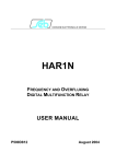
The relay contains a number of printed circuit boards as shown in Figure 2-1.
Instructions for removing each pcb are given in Section 10.
Screen plate
Main processor
board
Screen plate
DSP board
Screen plate
Power supply
board
User interface
board
Backplane
board
Analogue input
board
Analogue input
daugther board
REF current transformers
Figure 2-1:
Bias current input
transformers
Voltage transformer
Internal layout of relay.
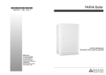
The relay is fully digital containing two microprocessors, a digital signal processor
(DSP) and a 80C196 which communicate with each other internally. The 80C196 is
responsible for the user interface, serial communications and scheme logic. The DSP
is responsible for the protection algorithms. The main functions performed in each
are shown in Figure 2-2.
KBCH/EN M/E11
CHAPTER 1
Page 10/76
Service Manual
Technical Description
KBCH 120, 130, 140
Optos
Protection
Status &
Magnitudes
Serial Data
from A/D
Relays
80C19
DSP
Settings
LCD Diplay
Serial Comms
Keypad
Low Set
High Set
Mag Inrush
Overflux Blocking
REF
Figure 2-2:
User Interface
Scheme Logic
Overflux Tripping & Alarm
Aux Time Delays
Functional block diagram
2.2
Signal Conditioning
2.2.1
Analogue to Digital conversion
The relay has up to sixteen analogue inputs, twelve are bias currents used in the
differential protection, three are currents used in the restricted earth fault (REF)
protection and one is a voltage used in the overflux protection. Each analogue input
is conditioned by a low pass anti-aliasing filter before passing to a 16 bit analogue to
digital converter via a 16 channel multiplexer. Each channel is sampled at forty times
per cycle, synchronised to the power system frequency. The digital data is passed to
a digital signal processor (DSP) which performs the protection algorithms.
2.2.2
Calibration
Calibration of each channel is performed in software, there are no hardware
adjustments in the relay. Calibration consists of gain and phase adjustment to
compensate for the hardware variations and the sequential sampling effect. Both
calibrations are done by adjusting the magnitude of each sample as they are read in
to the DSP. Phase calibration is not required for the REF and voltage channels as
phase plays no part in these algorithms.
2.2.3
Current Transformer (CT) ratio and phase compensation
Each of the bias current samples are further modified depending on the appropriate
relay settings for CT ratio and phase compensation as described in section 5.1.4.
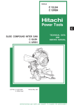
2.2.4
Transformer configuration
The transformer configuration setting is used to set unused channels to zero, to
ensure that they play no part in the algorithms. It also affects the relay measurements
and disturbance recorder functions as these display the current flowing into each of
the transformer windings. In cases where a single CT is used this is the same as the
bias current but where two CTs are used the winding current is calculated by
summing the two bias currents as shown in Figure 2-3.
Service Manual
Technical Description
KBCH 120, 130, 140
KBCH/EN M/E11
CHAPTER 1
Page 11/76
I2
Ihv
Ilv
I1
Ihv = I1 + I2
Figure 2-3:
2.2.5
Measurements for mesh corner applications
Differential current
The differential current, for each phase, is calculated by summing the four individual
bias currents related to that phase.
2.2.6
Fourier
The fundamental frequency magnitude and phase are calculated by a technique
which uses fourier transforms. A single cycle fourier is applied to each of the sixteen
channels, the three differential channels and the nine winding current channels.
Phase angle is not calculated for the three REF channels and the voltage channel as
these are not required for the algorithms. The fouriers are calculated eight times per
cycle.
2.2.7
Frequency tracking
The bias currents and voltage channels are used to determine the system frequency.
This is used to adjust the sample rate to maintain 40 samples per cycle and also in
the overflux protection algorithms.
2.3
Biased differential protection function
The relay contains two differential protection algorithms described below.
algorithm is applied to each of the three phases independently.
2.3.1
Each
Low set protection function
The biased low set differential element characteristic is shown in Figure 2-4. The
calculated bias current fourier magnitudes are summed to determine the through bias
current. The calculated fourier magnitude of the differential current is also used in
the algorithm. The minimum differential current required for operation is adjustable
between 0.1PU and 0.5PU based on rated current.
Under normal operation steady state magnetising current and the use of tap
changers result in unbalanced conditions and hence differential current. To
accommodate these conditions the initial slope is 20% for bias currents of zero up to
rated current. This ensures sensitivity to faults whilst allowing for up to 15% mismatch
when the power transformer is at the limit of its tap range. At currents above rated,
extra errors may be gradually introduced as a result of CT saturation. The bias slope
is therefore increased to 80% to compensate for this.
KBCH/EN M/E11
CHAPTER 1
Page 12/76
Service Manual
Technical Description
KBCH 120, 130, 140
3
2
Operate
Differential current (xIn) =
I1 + I2 + I3 + I4
8
1
Setting range
0.1 - 0.5In
e
lop
s
0%
Restrain
able
Allow tio error
a
20% r
lope
20% s
0
1
3
2
4
Effective Bias (xIn) = |I1| + |I2| + |I3| + |I4|
2
Figure 2-4:
2.3.2
Differential low set characteristic
Magnetising inrush current blocking
Particularly high inrush currents may occur on transformer energisation, depending
on the point on wave of switching as well as the magnetic state of the transformer
core. Since the inrush current flows only in the energised winding differential current
results. The use of traditional second harmonic restraint to block the relay during
inrush conditions may result in a significant slowing of the relay during heavy internal
faults due to the presence of second harmonics as a result of saturation of the line
current transformers. To overcome this, the relay uses a waveform recognition
technique to detect the inrush condition. The differential current waveform associated
with magnetising inrush is characterised by a period of each cycle where its
magnitude is very small, as shown in Figure 2-5. By measuring the time of this
period of low current, an inrush condition can be identified. The detection of inrush
current in the differential current is used to inhibit that phase of the low set algorithm.
A
B
C
Figure 2-5:
2.3.3
Typical magnetising inrush current waveforms
Overflux blocking
When a load is suddenly disconnected from a power transformer the voltage at the
input terminals of the transformer may rise by 10-20% of rated value causing an
appreciable increase in transformer steady state excitation current. The resulting
excitation current flows in one winding only and hence appears as differential current
which may rise to a value high enough to operate the differential protection. A
typical current waveform is shown in figure 2-6. A waveform of this type is
Service Manual
Technical Description
KBCH 120, 130, 140
KBCH/EN M/E11
CHAPTER 1
Page 13/76
characterised by the presence of fifth harmonic. A fourier technique is used to
measure the level of fifth harmonic in the differential current. The ratio of fifth
harmonic to fundamental is compared with a setting which if exceeded inhibits the
biased differential protection. Detection of overflux conditions in any phase blocks
that particular phase of the low set algorithm.
Figure 2-6:
2.3.4
Typical overflux current waveforms
High set protection function
An additional unrestrained instantaneous high set differential element is provided to
ensure rapid clearance of terminal faults. This element is essentially peak measuring
to ensure fast operation for internal faults with saturated CTs. The high set is not
blocked under magnetising inrush or over excitation conditions, hence the setting
must be set such that it will not operate for the largest inrush currents expected.
2.4
Restricted earth fault (REF) protection function
Restricted earth fault protection is included to give greater sensitivity to earth faults
and hence protect more of the winding. A separate element is provided for each
winding. An external resistor is required to provide stability in the presence of
saturated line current transformers.
The REF protection works on the high impedance circulating current principle as used
in the MCAG14 relays. When subjected to heavy through faults the line current
transformer may enter saturation unevenly, resulting in unbalance. To ensure
stability under these conditions the element uses a voltage operated, high impedance
circuit, set to operate at a voltage slightly higher than that developed by the current
transformers under maximum external fault conditions i.e. one CT fully saturated.
Harmonics, particular third, are rejected by basing the measurement on the
fundamental frequency fourier magnitude.
2.5
Overflux protection function
Power frequency overvoltage causes both an increase in stress on the insulation and
a proportionate increase in the working flux. The latter effect causes an increase in
the iron loss and a disproportionate increase in magnetising current. In addition flux
is diverted from the core into the steel structural parts, and in particular under
extreme over-excitation into the core bolts. These normally carry very little flux but
under these conditions they may be rapidly heated to a temperature which causes
their insulation to fail and eventually causes the main insulation to fail.
Over-excitation is caused by an increase in voltage or a reduction in frequency. It
follows therefore that transformers can withstand an increase in voltage with a
corresponding increase in frequency but not an increase in voltage with a decrease in
frequency.
KBCH/EN M/E11
CHAPTER 1
Page 14/76
Service Manual
Technical Description
KBCH 120, 130, 140
Operation cannot be sustained when the ratio of voltage to frequency, with these
quantities expressed as per unit of rated values, exceeds unity by more than a small
amount, for instance if V/f > 1.1. The base of “unit voltage” should be taken as the
highest voltage for which the transformer has been designed for.
Protection against overflux conditions does not call for high speed tripping, in fact
instantaneous tripping is undesirable as it would cause tripping for momentary system
disturbances which can be borne safely. Normal conditions must be resumed within
a minute or two at the most.
The relay contains two overflux algorithms, alarm and trip. The alarm, normally set
to operate at a lower level than the trip, will be used to initiate corrective action. Both
operate by comparing the ratio of Voltage to Frequency against a setting. The alarm
has a definite time delay, the trip has a choice of definite time delay or inverse
definite minimum time characteristic which is shown in Figure 2-7.
Operating time as a function of the actual excitation and the
set starting value for different time multiplier settings (K)
time (s)
1000
100
K = 63
K = 40
K = 20
10
K=5
K=1
1
1
1.1
1.2
1.3
M=
1.4
1.5
1.6
(V/f)
(V/f) setting
Figure 2-7:
2.6
Overflux tripping IDMT characteristic
Opto-isolated control inputs
There are eight opto-isolated control inputs to the relay and these can be arranged to
perform alternative functions as determined by the setting of the INPUT MASKS, so
making maximum use of the available control inputs. Software filtering is applied to
eliminate the adverse effects of induced ac signals in the external wiring.
2.7
Output relays
There are eight programmable output relays and these relays can be arranged to
operate in response to any, or all, of the available functions by suitably setting the
OUTPUT MASKS. In addition there is a watchdog relay for external indication of
equipment failure/healthy status.
2.8
Alternative setting group
An alternative group of settings is provided. The alternative settings can be selected
at any time, either by energising an opto-isolated control input assigned to this
function, or by a remote command via the serial communication port of the relay. A
decision has to be made during commissioning as to which method is to be used to
Service Manual
Technical Description
KBCH 120, 130, 140
KBCH/EN M/E11
CHAPTER 1
Page 15/76
select the alternative setting group. It is not possible to select by both local and
remote control at the same time.
2.9
Logic
All the settings for the auxiliary timing functions are located under the LOGIC
heading of the menu.
There are eight auxiliary timers in the relays which may be used as discrete time
delays for external functions. They may be initiated via the opto-isolated control
inputs and their outputs directed to any of the output relays by suitably setting the
associated RELAY MASKS.
2.10
Measurement
All measurement values can be displayed on the front of the relay. The display
consists of up to nine phase current values depending on model and configuration.
The currents displayed are those measured before the effects of phase compensation.
If the primary current transformer ratios are entered in the SETTINGS column the
phase current values will be in primary amperes. The default setting for these ratios
is 1:1; in which case the displayed measured values are then the secondary quantities
as seen by the relay. In the case of “mesh corner” where two current transformers
are used the displayed currents are the calculated current which is flowing in the
transformer winding. The differential and through bias currents are displayed in
secondary terms. The minimum current that is measured by KBCH is 30mA or
150mA for 1A or 5A respectively.
2.11
Fault records
Fault values are recorded for the last fault but the fault flags are recorded for the last
five faults. They are stored in non-volatile memory and can be accessed via the user
interface. There is provision for clearing these records.
A copy of the fault record is also stored in the event records and up to 50 of these
records can be held at any one time, provided all other events are de-selected.
These records will carry a time tag which is valid for 49 days. However, the event
records will be lost if the relay is de-energised and they can only be accessed via the
serial communication port.
2.12
Self monitoring and protection alarms
The monitoring circuits within the relay continuously perform a self test routine. Any
detected loss of operation in the first instance initiates a reset sequence to return the
equipment to a serviceable state. The voltage rails are also supervised and the
processors are reset if the voltage falls outside their working range. Should the main
processor fail and not restart, the watchdog relay will provide an alarm. This relay
will also signal an alarm on loss of the auxiliary energising supply to the relay.
In addition, the memory of the relay is checked for possible corruption of data and
any detected errors will result in an alarm being generated. An ALARM LED indicates
several states which can be identified by viewing the alarm flags that are to be found
towards the end of the SYSTEM DATA column of the menu and consist of seven
characters that may be either ”1” or “0” to indicate the set and reset states of the
alarm. The flags offer the following indications:
KBCH/EN M/E11
CHAPTER 1
Page 16/76
Service Manual
Technical Description
KBCH 120, 130, 140
Alarm Flags
6
5
4
3
2
Indication
1
0
1
1
1
1
1
1
1
Unconfig
Protection not operational –
needs to be configured
Uncalib
Protection is running
uncalibrated – calibration
error
Setting
Protection is running –
possible setting error
No service
Protection is out of service
No opto
Protection not sampling
opto inputs
No S/Logic
Protection not operational –
scheme logic not running
DSP Faulty
Protection not operational –
Fault detected in DSP
For the above listed alarms the ALARM LED will be continuously lit, the alarm bit will
be set in the STATUS word as a remote alarm and the watchdog relay will operate.
However, there is another form of alarm that causes the ALARM LED to flash; this
indicates that the password has been entered to allow access to change protected
settings within the relay and this is not generally available as a remote alarm.
Note:
2.13
No control will be possible via the key pad if the “Unconfigured”
alarm is raised because the relay will be locked in a non-operate
state.
Password protection
Password protection is only provided for the configuration settings of the relay. This
includes transformer configuration, phase compensation selection, CT ratio
correction, CT ratios, function link settings, opto-input and relay output allocation.
Any accidental change to configuration could seriously affect the ability of the relay to
perform its intended functions, whereas, a setting error may only cause a grading
problem. Individual protection settings are protected from change when the relay
cover is in place.
2.14
Serial communication
Serial communications are supported over K-BUS, a multidrop network that readily
interfaces to IEC870-5 FT1.2 Standards. The language and protocol used for
communication is Courier. It has been especially developed to enable generic Master
Station programs to access many different types of relay without continual
modification to the Master Station program. The relays form a distributed data base
for the Master Station and may be polled for any information required. This includes:
1.
Measured values
2.
Menu text
3.
Settings and setting limits
4.
Fault records
5.
Event records
Service Manual
Technical Description
KBCH 120, 130, 140
KBCH/EN M/E11
CHAPTER 1
Page 17/76
6.
Disturbance records
7.
Status - an eight bit word that identifies the trip and alarm state, busy state, also
the presence of event and disturbance records for collection.
2.14.1 Time tagged event records
An event may be a change of state of a control input or an output relay; it may be a
setting that has been changed locally; a protection or control function that has
performed its intended function. A total of 50 events may be stored in a buffer, each
with an associated time tag. This time tag is the value of a timer counter that is
incremented every 1 millisecond.
The event records can only be accessed via the serial communication port when the
relay is connected to a suitable Master Station. When the relay is not connected to a
Master Station the event records can still be extracted within certain limitations:
−
the event records can only be read via the serial communication port and a KBUS/IEC870-5 Interface Unit will be required to enable the serial port to be
connected to an IBM or compatible PC. Suitable software will be required to
run on the PC so that the records can be extracted.
−
when the event buffer becomes full the oldest record is overwritten by the next
event.
−
records are deleted when the auxiliary supply to the relay is removed, to ensure
that the buffer does not contain invalid data.
−
the time tag will be valid for 49 days assuming that the auxiliary supply has not
been lost within that time. However, there may be an error of ±4.3s in every
24 hour period due to the accuracy limits of the crystal. This is not a problem
when a Master Station is on line as the relays will usually be polled once every
second or so.
Events that are recorded include:
1.
change in state of logic inputs
2.
change in state of relay outputs
3.
change to settings made locally
4.
fault records as defined in the FAULT RECORDS column of the menu
5.
alarm messages
Items 1 and 2 may be deleted from the events so that up to 50 fault records may be
stored.
2.14.2 Disturbance records
The internal disturbance recorder has sixteen analogue channels plus one to record
the status of the eight control inputs and one to record the status of the eight relay
outputs. The analogue channels record up to nine phase currents, three per winding,
the three differential currents, the three calculated through bias currents and the
voltage channel. In the case of “mesh corner” where two current transformers are
used the phase currents are the calculated current which is flowing in the transformer
winding. As with the event recorder, when the buffer is full the oldest record is
overwritten and records are deleted if the auxiliary supply to the relay is removed.
This ensures that when the buffer is read the contents will all be valid.
KBCH/EN M/E11
CHAPTER 1
Page 18/76
Service Manual
Technical Description
KBCH 120, 130, 140
The disturbance recorder is stopped and the record frozen a set time after a selected
trigger has been activated. For example, a protection trip command could be the
selected trigger and the delay would then set the duration of the trace after the fault.
Each sample has a time tag attached to it so that when the waveform is reconstituted
it can be plotted at the correct point against the time scale, thus ensuring that the time
base is correct and independent of the frequency.
The disturbance records can only be accessed via the serial communication port.
2.14.3 Remote control functions
Control functions that affect the relay and that can be performed over the serial link
include the change of individual relay settings and the change between setting
groups. Plant control functions include remote manual tap up/tap down.
Note:
If it is considered essential that it must not be possible to perform
certain of these remote control functions, they can be inhibited
by setting software links in the relay. These links are password
protected, see Section 5.
2.14.4 Notes on serial port
Each relay in the K-Series has a serial communication port configured to K-BUS
Standards. K-BUS is a communication interface and protocol designed to meet the
requirements of communication with protective relays and transducers within the
power system substation environment. It has to be as reliable as the protective relays
themselves and must not result in their performance being degraded in any way.
Hence error checking and noise rejection have been major concerns in its design.
The communication port is based on RS485 voltage transmission and reception levels
with galvanic isolation provided by a transformer. A polled protocol is used and no
relay unit is allowed to transmit unless it receives a valid message, without any
detected error, addressed to it. Transmission is synchronous over a pair of screened
wires and the data is FM0 coded with the clock signal to remove any dc component
so that the signal will pass through transformers. This method of encoding the data
allows the connection to the bus wiring to be made in either polarity.
With the exception of the Master Units, each node in the network is passive and any
failed unit on the system will not interfere with communication to the other units. The
frame format is high level data link control (HDLC) and the data rate is 64kbits/s. Up
to 32 units may be connected to any bus at any point with a maximum length of
1000m.
2.14.5 Notes on security of remote control via the serial port
Access to the memory of the relay is restricted to that addressed via the menu system
of the relay. In addition, all setting changes are reflexed back to the Master Station
for verification before the EXECUTE command is issued. On reception of the
EXECUTE command the new setting is checked against the limits stored in the relay
before they are entered. Only then does the relay respond to the new setting.
All remote commands are reflexed back to the Master Station for verification before
they are executed and any command left set is automatically rejected if not executed
within the time-out period. No replies are permitted for global commands as this
would cause contention on the bus; instead a double send is used for verification
purposes with this type of command.
Remote control is restricted to those functions that have been selected in the relay’s
menu table and the selection cannot be changed without entering the password.
Cyclical redundancy checksum (CRC) and message length checks are used on each
Service Manual
Technical Description
KBCH 120, 130, 140
KBCH/EN M/E11
CHAPTER 1
Page 19/76
message received. No response is given for received messages with a detected error.
The Master Station can be set to re-send a command a set number of times if it does
not receive a reply or receives a reply with a detected error.
3.
EXTERNAL CONNECTIONS
Function
Terminal
Function
Earth Terminal
-
1
2
-
Not Used
Watchdog Relay
(Break contact)
b
-
3
5
4
6
m
-
(Make contact)
48V Field Voltage
[+]
7
8
[−]
48V Field Voltage
Not Used
-
9
10
-
Not Used
Not Used
-
11
12
-
Not Used
Auxiliary Voltage Input
(+)
13
14
(−)
Auxiliary Voltage Input
Not Used
-
15
16
-
Not Used
Voltage Input (Overflux)
In
17
18
Out
Voltage Input
(Overflux)
Not Used
-
19
20
-
Not Used
A Current (1)
In
21
22
Out
A Current (1)
B Current (1)
In
23
24
Out
B Current (1)
C Current (1)
In
25
26
Out
C Current (1)
E/F Current (1)
In
27
28
Out
E/F Current (1)
Function
Terminal
Function
Output Relay 4
-
29
31
30
32
-
Output Relay 0
Output Relay 5
-
33
35
34
36
-
Output Relay 1
Output Relay 6
-
37
39
38
40
-
Output Relay 2
Output Relay 7
-
41
43
42
44
-
Output Relay 3
Opto Control Input L3
(+)
45
46
(+)
Opto Control Input L0
Opto Control Input L4
(+)
47
48
(+)
Opto Control Input L1
Opto Control Input L5
(+)
49
50
(+)
Opto Control Input L2
Opto Control Input L6
(+)
51
52
(-)
Common L0/L1/L2
Opto Control Input L7
(+)
53
54
-
K-BUS Serial Port
Common L3/L4/L5/L6/L7
(+)
55
56
-
K-BUS Serial Port
Earth Terminal
-
57
58
-
Not Used
Not Used
-
59
60
-
Not Used
Not Used
-
61
62
-
Not Used
KBCH/EN M/E11
CHAPTER 1
Page 20/76
Service Manual
Technical Description
KBCH 120, 130, 140
Function
Terminal
Function
A Current (4)
In
63
64
Out
A Current (4)
(KBCH140 only)
B Current (4)
In
65
66
Out
B Current (4)
(KBCH140 only)
C Current (4)
In
67
68
Out
C Current (4)
(KBCH140 only)
A Current (3)
In
69
70
Out
A Current (3)
(Not on KBCH120)
B Current (3)
In
71
72
Out
B Current (3)
(Not on KBCH120)
C Current (3)
In
73
74
Out
C Current (3)
(Not on KBCH120)
E/F Current (3)
In
75
76
Out
E/F Current(3)
(Not on KBCH120)
A Current (2)
In
77
78
Out
A Current (2)
B Current (2)
In
79
80
Out
B Current (2)
C Current (2)
In
81
82
Out
C Current (2)
E/F Current (2)
In
83
84
Out
E/F Current (2)
Key to connection tables
[+] and [−] indicate the polarity of the dc output from these terminals.
(+) and (−) indicate the polarity for the applied dc supply.
In / Out
the signal direction for forward operation.
Note:
3.1
All relays have standard Midos terminal blocks to which
connections can be made with either 4mm screws or 4.8mm
pre-insulated snap-on connectors. Two connections can be
made to each terminal.
Auxiliary supply
The auxiliary voltage may be ac or dc provided it is within the limiting voltages for the
particular relay. The voltage range will be found on the front plate of the relay; it is
marked (Vx = 24V − 125V) or (Vx = 48V − 250V). An ideal supply to use for testing
the relays will be 50V dc or 110V ac because these values fall within both of the
auxiliary voltage ranges.
The supply should be connected to terminals 13 and 14 only. To avoid any
confusion it is recommended that the polarity of any applied voltage is kept to the
Midos standard:
−
for dc supplies the positive lead connected to terminal 13 and the negative to
terminal 14.
−
for ac supplies the live lead is connected to terminal 13 and the neutral lead to
terminal 14.
Note:
To avoid damage to the relay do not connect any auxiliary
supplies to terminals 7 and 8.
Service Manual
Technical Description
KBCH 120, 130, 140
3.2
KBCH/EN M/E11
CHAPTER 1
Page 21/76
Opto-isolated control inputs
The opto-isolated control inputs are rated for 48V dc and energised from the isolated
48V field voltage provided on terminals 7 and 8 of the relay. Terminal 8 (−) must be
connected to terminals 52 and 55. The opto-isolated control inputs can then be
energised by connecting a volt free contact between terminal 7 (+) and the terminal
associated with the required input, L0 to L7, given in the above table.
The circuit for each opto-isolated input contains a blocking diode to protect it from
any damage that may result from the application of voltage with incorrect polarity.
Where the opto-isolated input of more than one relay is to be controlled by the same
contact it will be necessary to connect terminal 7 of each relay together to form a
common line. In the example, shown in Figure 3-1, contact X operates L1 of relay 1
and contact Y operates L0 of relay 1 as well as L0 and L1 of relay 2. L2 is not used
on either relay and has no connections made to it.
L0
L1
L2
46
46
48
48
50
50
52
52
X
_
Figure 3-1:
3.3
L1
L2
Y
8
48V
7
+
Relay 1
L0
Common line
8
_
7
48V
+
Relay 2
Connection to optical isolator control inputs
Analogue inputs
The relays can have up to sixteen analogue inputs depending on the model. Each is
fed via an input transducer and low pass filter to a multiplexer and analogue to
digital converter. The analogue signals are sampled forty times per cycle on each
channel as the sampling rate tracks the frequency of the input signal.
3.4
Output relays
There are four programmable output relays on the microprocessor board and four on
the DSP board. These relays each have two make contacts connected in series to
increase their rating. The protection and control functions to which these relays
respond are selectable via the menu system of the relay. It is normal practice to
allocate RLY3 and RLY7 as trip relays as these relays also control the flagging (see
section 6.9).
In addition there is a watchdog relay which has one make and one break contact.
Thus it can indicate both healthy and failed conditions. As these contacts are mainly
used for alarm purposes, single contacts are used and their rating is therefore not
quite as high as that of the programmable outputs.
The terminal numbers for the output relay contacts are given in the table at the start
of Section 3.
KBCH/EN M/E11
CHAPTER 1
Page 22/76
3.5
Service Manual
Technical Description
KBCH 120, 130, 140
Alternative trip arrangements
Normal practice is to use a separate trip contact for each of the circuit breakers
associated with the transformer.
3.5.1
DC shunt trip
An auxiliary supply is required to trip the circuit breakers. This will normally be a dc
supply which is generally considered to be more secure than an ac supply. It would
be usual to use a shunt trip coil for dc energised trip circuits as shown in Figure 3-2.
The trip circuit current will normally be broken by an auxiliary contact on the circuit
breaker once the circuit breaker has opened. If this is not the case then a trip relay
with heavy duty contacts must be interposed between the relay trip contact and the
trip coil.
4
RLY3
+
4
Trip
supply
Trip
Relay
Figure 3-2:
3.5.2
_
DC shunt trip arrangement
AC no-volt trip
For ac tripping it may be considered safer to opt for an no-volt trip release. Tripping
from a make contact on the relay is still possible by using the circuit shown in Figure
3-3.
This arrangement will also trip the circuit breaker when the auxiliary trip supply is lost.
If the circuit breaker is fitted with a line VT, then this may be used to provide the trip
supply for the circuit breaker and the circuit breaker will then be tripped when the
protected circuit is de-energised.
The capacitor is included to reduce the release time and would tune the coil to the
power frequency. The series resistor would then limit the current in the coil to its
rated value.
Relay
4
RLY3
Figure 3-3:
4
AC no volt trip arrangement
Trip
Trip
supply
Service Manual
Technical Description
KBCH 120, 130, 140
Serial communication port (K-BUS)
Connection to the K-BUS Port is by standard Midos 4mm screw terminals or push-on
connectors. A twisted pair of wires is all that is required; the polarity of connection is
not important. It is recommended that an outer screen is used with an earth
connected to the screen at the Master Station end only. Termination of the screen is
effected with the ”U” shaped terminal supplied and which has to be secured with a
self tapping screw in the hole in the terminal block just below terminal 56 (see Figure
3-4). Operation has been tested up to 1,000 metres with cable to:
−
DEF Standard 16-2-2c
−
16/0.2mm dia
−
40mΩ/m per core
−
171pf/m core/core
−
288pf/m core/screen
The minimum requirement to communicate with the relay is a K-BUS/IEC870-5
converter box Type KITZ101/102 and suitable software to run on an IBM or
compatible personal computer.
Note:
K-Bus must be terminated with a 150Ω resistor at each end of
the bus. The Master Station can be located at any position, but
the bus should only be driven from one unit at a time.
54
This interface provides the user with a means of entering settings to the relay and of
interrogating the relays to retrieve recorded data.
56
3.6
KBCH/EN M/E11
CHAPTER 1
Page 23/76
Figure 3-4:
Termination arrangement for communications
KBCH/EN M/E11
CHAPTER 1
Page 24/76
Service Manual
Technical Description
KBCH 120, 130, 140
4.
USER INTERFACE
4.1
Front plate layout
The front plate of the relay carries an identification label at the top right hand corner.
This identifies the relay by both its model number and serial number. This
information is required when making any enquiry to the factory about a particular
relay because it uniquely specifies the product. In addition there is a rating label in
the bottom left hand corner which gives details of the auxiliary voltage Vx, reference
voltage Vn and current ratings Ιn (see Figure 4-1).
Two handles, one at the top and one at the bottom of the front plate, will assist in
removing the module from the case. Three light emitting diodes (LEDs) provide status
indication and, in addition, a liquid crystal display and a four key pad for access to
settings and other readable data.
Model number
Relay type
Liquid
crystal
display
KBCH12001H12LEA
No 000001A
KBCH120
Serial number
Digital identifiers
AUX0=
Led
indicators
FEDCBA9876543210
AUX1=
AUX2=
ALARM
AUX3=
TRIP
AUX4=
AUX5=
F
0
AUX6=
AUX7=
Made in UK
Ratings
In
Vn
Figure 4-1:
4.2
1
Entry keys
A Vx 24/125 V ~
V~ 50/60 Hz
100/120
Front plate layout
LED indications
The three LEDs provide the following functions:
GREEN LED
Indicates the relay is powered up and running. It reflects the
state of the watchdog relay.
YELLOW LED
Indicates alarm conditions that have been detected by the
relay. These may be external alarms via the logic inputs or
alarms detected during its self checking routine. The alarm
lamp flashes when the password is entered (password
inhibition temporarily overridden).
RED LED
Indicates a trip that has been issued by the relay. The trip flags
give further information.
Service Manual
Technical Description
KBCH 120, 130, 140
4.3
KBCH/EN M/E11
CHAPTER 1
Page 25/76
Keypad
Four keys on the front plate of the relay enable the user to select the data to be
displayed and settings to be changed. The keys perform the following functions:
4.4
[F]
- FUNCTION SELECT KEY
[+]
- INCREMENT VALUE KEY
[−]
- DECREMENT VALUE KEY
[0]
- RESET/ESCAPE KEY
Liquid crystal display
The liquid crystal display (LCD) has two lines, each of sixteen characters, that are
used to display settings, measured values and records which are extracted from the
relay data bank. A backlight is activated when any of the keys on the front plate of
the relay is momentarily pressed. This enables the display to be read in all conditions
of ambient lighting.
The numbers printed on the front plate just below the display, identify the individual
digits that are displayed for some of the settings, i.e. function links, relay masks etc.
KBCH/EN M/E11
CHAPTER 1
Page 26/76
5.
Service Manual
Technical Description
KBCH 120, 130, 140
MENU SYSTEM
Data within the relays is accessed via a MENU table. The table is divided into
columns and rows to form cells, rather like a spreadsheet. Each cell may contain text,
values, limits and functions. The first cell in a column contains a heading which
identifies the data grouped on that column (see Figure 5-1).
F2
F1
F
F
LONG
F SHORT
Figure 5-1:
F3
LONG
F SHORT
F SHORT
F5
F4
F
F
LONG
LONG
F SHORT
F
LONG
F SHORT
Menu system of relay
Four keys on the front plate of the relay allow the menu to be scanned and the
contents displayed on the liquid crystal display (LCD). The act of depressing any key
will result in the LCD backlight being switched on. The backlight will turn off again if
a key is not pressed again within one minute.
The display will normally be the selected default setting and a momentary press of the
function key [F] will change the display to the heading for the first column, SYSTEM
DATA. Further momentary presses of the [F] key will step down the column, row by
row, so that data may be read. If at any time the [F] key is pressed and held for one
second the cursor will be moved to the top of the next column and the heading for
that column will be displayed. Further momentary presses of the [F] key will then
move down the new column, row by row. In this way the full menu of the relay may
be scanned with just one key and this key is accessible with the cover in place on the
relay.
The other key that is accessible with the cover in place is the reset key [0]. A
momentary press of this key will switch on the back light for the LCD without
changing the display in any way. Following a protection trip the display will change
automatically from the default display to that of the fault flags for that fault and the
red trip LED will be lit to draw attention to this Input (Overflux). The trip LED can be
reset by holding down the reset key [0] for at least one second.
The fault information is not lost by this action, it is only cleared from the display. The
fault flags can be read by selecting FAULT RECORDS from the column headings and
stepping down until the flag data (Fn), the flags for the last fault, are displayed. The
red trip LED can be reset by holding the reset key [0] depressed for 1 second whilst
this cell is being displayed. The next cell down contains the flags for the previous
fault (Fn−1) and so on to (Fn−4). The currents measured during the last fault are also
recorded on this page of the menu. To delete all fault records the next cell after
Service Manual
Technical Description
KBCH 120, 130, 140
KBCH/EN M/E11
CHAPTER 1
Page 27/76
(Fn−4) must be selected. This cell will read “FLT Records Clear = [0]” and to
complete the reset action the [0] key must be held depressed for more than 1 second.
The only settings which can be changed with the cover in place are those that can be
reset either to zero or some pre-set value. To change any other settings the cover has
to be removed from the relay to gain access to the [+] and [−] keys, that are used to
increment or decrement a value. When a column heading is displayed the [−] key
will change the display to the next column and the [+] key will change the display to
the previous column, giving a faster selection.
When a cell containing a relay setting is displayed the action of pressing either the
[+] or [−] keys will indicate to the relay that a value is to be changed and a flashing
cursor will appear on the display. To escape from the setting mode without making
any change, the [0] key should be depressed for one second.
For instruction on how to change the various types of settings refer to Section 5.2.
5.1
Menu contents
Related data and settings are grouped together in separate columns of the menu.
Each column has a text heading that identifies the data contained in that column.
Each cell may contain text, values, limits and/or a function. The cells are referenced
by the column number/row number. For example 0201 is column 02, row 01.
The full menu is given in the following notes but not all the items will be available in a
particular relay. For example, a KBCH120 relay would not display any settings
related to the tertiary winding (LV2). Those cells that do not provide any useful
purpose are not made available in the factory configuration, to avoid the confusion
that would occur in deciding what values to set them to. In a similar way certain
settings will disappear from the menu when the user de-selects them; the alternative
setting group is a typical example. If System Data Link (SD4) is set to “0” alternative
settings SETTINGS(2) will be hidden and to select them and make them visible, link
SD4 must be set to “1”. This note is included at this time to explain why some of the
items listed below may not appear in the menu for the relay that is being compared
with the full list.
The menu cells that are read only are marked [READ].
Cells that can be set are marked [SET].
Cells that can be reset are marked [RESET].
Cells that are password protected are marked [PWP].
5.1.1
System data
0000 SYSTEM DATA
0001 SYS Language
The language used in the text [READ]
0002 SYS Password
Password [PWP]
0003 SYS Fn Links
Function Links [PWP]
LINK 0 [SYS Rem ChgStg ]
1 = Enable remote setting changes
LINK 1 [SYS Rem Tap Ctrl]
1 = Enable remote control of tap changer
LINK 3 [SYS Rem ChgGrp]
1 = Enable remote change of setting group
LINK 4 [SYS Enable Grp2 ]
1 = Enable setting group 2
LINK 5 [SYS Auto Reset]
1 = Enable auto flag reset function
LINK 6 [SYS Auto Rec]
1 = Enable auto reset of recorder
KBCH/EN M/E11
CHAPTER 1
Page 28/76
LINK 7 [SYS En Log Evts ]
Service Manual
Technical Description
KBCH 120, 130, 140
1 = Enable event records to be stored
0004 SYS Description
Description or user scheme identifier [PWP]
0005 SYS Plant Ref.
User plant/location identifier [PWP]
0006 SYS Model No.
Model number [READ]
0008 SYS Serial No.
Serial number [READ]
0009 SYS Frequency
Frequency [SET]
000A SYS Comms Level
Communication level [READ]
000B SYS Rly Address
Communication address [SET]
000C SYS Plant Status
Not used [READ]
000D SYS Ctrl Status
Not used [READ]
000E SYS Setting Grp
Setting group in use (1/2) [READ]
0011 SYS S/W Ref 1
Software reference number 1 [READ]
0012 SYS S/W Ref 2
Software reference number 2 [READ]
0020 SYS Logic Stat
Current state of logic control inputs [READ]
0021 SYS Relay Stat
Current state of output relays [READ]
0022 SYS Alarms
State of alarms [READ]
The following notes describe each setting:
0001 SYS Language [READ]
The language in which the text is displayed is shown at this location.
particular relays it is not selectable.
On these
0002 SYS Password [PWP]
The selected configuration of the relay is locked under this password and cannot be
changed until it has been entered. Provision has been made for the user to change
the password, which may consist of four upper case letters in any combination. In the
event of the password becoming lost a recovery password can be obtained on
request, but the request must be accompanied by a note of the model and serial
numbers of the relay. The recovery password will be unique to one relay and will not
work on any other unless the user set password is the same.
0003 SYS Function Links [PWP]
These function links enable selection to be made from the system options, for
example, which commands over the serial link will be acted upon.
0004 SYS Description [PWP]
This is text that describes the relay type, for example “2 Bias I/P + REF”. It is
password protected and can be changed by the user to a name which may describe
the scheme configuration of the relay if the relay is changed from the factory
configuration.
0005 SYS Plant Reference [SET]
The plant reference can be entered by the user, but it is limited to 16 characters. This
reference is used to identify the primary plant with which the relay is associated.
Service Manual
Technical Description
KBCH 120, 130, 140
KBCH/EN M/E11
CHAPTER 1
Page 29/76
0006 SYS Model Number [READ]
The model number that is entered during manufacture has encoded into it the
mechanical assembly, ratings and configuration of the relay. It is printed on the front
plate and should be quoted in any correspondence concerning the product.
0008 SYS Serial Number [READ]
The serial number is the relay identity and encodes also the year of manufacture. It
cannot be changed from the menu.
0009 SYS Frequency [SET]
The set frequency from which the relay starts tracking on power-up.
000A SYS Communication Level [READ]
This cell will contain the communication level that the relay will support. It is used by
Master Station programs to decide what type of commands to send to the relay.
000B SYS Relay Address [SET]
An address between 1 and 254 that identifies the relay when interconnected by a
communication bus.
These addresses may be shared between several
communication buses and therefore not all these addresses will necessarily be
available on the bus to which the relay is connected. The address can be manually
set. Address 0 is reserved for the automatic address allocation feature and 255 is
reserved for global messages. The factory set address is 255.
000C SYS Plant Status [READ]
The plant status is not used in these relays.
000D SYS Control Status [READ]
The control status is not used in these relays.
000E SY Setting Group [READ]
Where a relay has alternative groups of settings which can be selected, then this cell
indicates the current group being used by the relay. For these relays it is either
(Group 1) or (Group 2).
0011 SYS S/W Ref 1 [READ]
The version of software for the microprocessor is coded into this number. It cannot
be changed.
0012 SYS S/W Ref 2 [READ]
The version of software for the DSP is coded into this number. It cannot be changed.
0020 SYS Logic Stat
Current state of opto-isolated logic control inputs. Note this function is repeated in
cell 0D01.
0021 SYS Relay Stat
Current state of relay outputs. Note this function is repeated in cell 0D02.
0022 SYS Alarms
Current state of alarm flags (see Section 5.2.11).
KBCH/EN M/E11
CHAPTER 1
Page 30/76
5.1.2
5.1.3
Service Manual
Technical Description
KBCH 120, 130, 140
Fault records
01 00
FAULT RECORDS
[READ]
01 01
FLT Ιa HV
Fault Current in HV winding A phase
01 02
FLT Ιb HV
Fault Current in HV winding B phase
01 03
FLT Ιc HV
Fault Current in HV winding C phase
01 05
FLT Ιa LV1
Fault Current in LV1 winding A phase
01 06
FLT Ιb LV1
Fault Current in LV1 winding B phase
01 07
FLT Ιc LV1
Fault Current in LV1 winding C phase
01 09
FLT Ιa LV2
Fault Current in LV2 winding A phase
01 0A
FLT Ιb LV2
Fault Current in LV2 winding B phase
01 0B
FLT Ιc LV2
Fault Current in LV2 winding C phase
01 0D
FLT Ιa Diff
Fault Current in Differential circuit A phase
01 0E
FLT Ιb Diff
Fault Current in Differential circuit B phase
01 0F
FLT Ιc Diff
Fault Current in Differential circuit C phase
01 10
FLT Ιa Bias
Fault Current in Bias circuit A phase
01 11
FLT Ιb Bias
Fault Current in Bias circuit B phase
01 12
FLT Ιc Bias
Fault Current in Bias circuit C phase
01 13
FnowGx
Current state of flags (not latched)
01 14
Fn-Gx
flags for last fault (n) [RESET trip led only]
01 15
Fn−1Gx
flags for previous fault (n−1) - previous fault
01 16
Fn−2Gx
flags for previous fault (n−2)
01 17
Fn−3Gx
flags for previous fault (n−3)
01 18
Fn−4Gx
flags for previous fault (n−4)
01 19
FLT Records Clear = [0] Clear fault records [RESET]
Measurements(1)
02 00
MEASUREMENTS(1)
[READ]
02 01
MS1 Ιa HV
Current in HV winding A phase
02 02
MS1 Ιb HV
Current in HV winding B phase
02 03
MS1 Ιc HV
Current in HV winding C phase
02 05
MS1 Ιa LV1
Current in LV1 winding A phase
02 06
MS1 Ιb LV1
Current in LV1 winding B phase
02 07
MS1 Ιc LV1
Current in LV1 winding C phase
02 09
MS1 Ιa LV2
Current in LV2 winding A phase
02 0A
MS1 Ιb LV2
Current in LV2 winding B phase
02 0B
MS1 Ιc LV2
Current in LV2 winding C phase
02 0D
MS1 Ιa Diff
Current in Differential circuit A phase
02 0E
MS1 Ιb Diff
Current in Differential circuit B phase
02 0F
MS1 Ιc Diff
Current in Differential circuit C phase
02 10
MS1 Ιa Bias
Current in Bias circuit A phase
Service Manual
Technical Description
KBCH 120, 130, 140
5.1.4
KBCH/EN M/E11
CHAPTER 1
Page 31/76
02 11
MS1 Ιb Bias
Current in Bias circuit B phase
02 12
MS1 Ιc Bias
Current in Bias circuit C phase
02 13
MS1 F
Settings(1)
System frequency
05 00
SETTINGS(1)
[SET]
05 01
S1 Fn. Links
Setting 1 function links [PWP]
Link 1 [S1 Enable Ιd>
]
1 = Enable low set
Link 2 [S1 Enable Ιd>>
]
1 = Enable high set
Link 3 [S1 Enable Ιo> HV
]
1 = Enable REF on HV winding
Link 4 [S1 Enable Ιo> LV1 ]
1 = Enable REF on LV winding
Link 5 [S1 Enable Ιo> LV2 ]
1 = Enable REF on Tertiary winding (not
KBCH120)
Link 7 [S1 Enable OF Trip
]
1 = Enable Overflux Trip
Link 8 [S1 Enable OF Alm
]
1 = Enable Overflux Alarm
Link 9 [S1 Enable OF Blk
]
1 = Enable Overflux Block
05 02
S1 Configuration
See Note below [PWP]
05 03
S1 HV CT Ratio
HV side CT Ratio [PWP]
05 04
S1 LV1 CT Ratio
LV side CT Ratio [PWP]
05 05
S1 LV2 CT Ratio
LV2 side CT ratio (not KBCH120) [PWP]
05 06
S1 HV Ratio Cor
HV side CT correction ratio [PWP]
05 07
S1 HV VectorCor
HV Phase compensation [PWP]
05 08
S1 LV1 Ratio Cor
LV1 side CT correction ratio [PWP]
05 09
S1 LV1 VectorCor
LV1 Phase compensation [PWP]
05 0A
S1 LV2 Ratio Cor
LV2 side CT correction ratio (not
KBCH120) [PWP]
05 0B
S1 LV2 VectorCor
LV2 Phase compensation (not KBCH120)
[PWP]
05 0C
S1 Ιd>
Low set setting
05 0D
S1 Ιd>>
High set setting
05 0E
S1 Ιo> HV
REF setting HV winding
05 0F
S1 Ιo> LV1
REF setting LV winding
05 10
S1 Ιo> LV2
REF setting Tertiary winding (not
KBCH120)
05 11
S1 Ιof
5th harmonic Overflux setting
05 12
S1 tOF
5th harmonic Overflux detector time delay
05 15
S1 V/f(Trip)Char
Overflux Trip Characteristic
05 16
S1 V/f (Trip)
Setting for Overflux Trip
05 17
S1 tV/f (Trip)
Definite time setting for Overflux Trip
05 18
S1 V/f (Trip)TMS
Time multiplier for Overflux Trip
05 19
S1 V/f (Alarm)
Setting for Overflux Alarm
05 1A
S1 tV/f (Alarm)
Definite time setting for Overflux Alarm
KBCH/EN M/E11
CHAPTER 1
Page 32/76
Service Manual
Technical Description
KBCH 120, 130, 140
Notes on Configuration setting:
Setting
No of Bias
Inputs
HV+LV
2 bias inputs
HV+LV1+LV2
3 bias inputs
Configuration
Applicable to
KBCH120/130/140
HV
LV
LV1
HV(x2)+LV
KBCH130/140
HV
3 bias inputs
LV2
KBCH130/140**
HV
LV
HV+LV(x2)
3 bias inputs
KBCH130/140
HV
LV
HV(x2)+LV1+LV2
4 bias inputs
LV1
HV+LV1(x2)+LV2
4 bias inputs
LV2
Only KBCH140**
HV
LV1
HV(x2)+LV(x2)
Only KBCH140
HV
4 bias inputs
LV2
HV
Only KBCH140
LV
** Not available in Ιn = HV 1A/LV 5A versions of KBCH140
Notes on VectorCor setting:
Setting
Action
Phase Shift
Yy0
Do nothing
0û
Yd1
Ιa = (ΙA – ΙC) / 3
Ιb = (ΙB – ΙA) / 3
Ιc = (ΙC – ΙB) / 3
30û lag
Yd2
Ιa = (ΙA + ΙB)
Ιb = (ΙB + ΙC)
Ιc = (ΙC + ΙA)
60û lag
Yd3
Ιa = (ΙB – ΙC) / 3
Ιb = (ΙC – ΙA) / 3
Ιc = (ΙA – ΙB) / 3
90û lag
Yd4
Ιa = ΙB
Ιb = ΙC
Ιc = ΙA
120û
Yd5
Yd11 and Invert
150û lag
Yy6
Invert currents
180û lag
Yd7
Yd1 and Invert
150û lead
Yd8
Yd2 and Invert
120û lead
Where Ιa is the
corrected current and
ΙA is the uncorrected
current
Service Manual
Technical Description
KBCH 120, 130, 140
5.1.5
KBCH/EN M/E11
CHAPTER 1
Page 33/76
Setting
Action
Phase Shift
Yd9
Yd3 and Invert
90û lead
Yd10
Yd4 and Invert
60û lead
Yd11
Ιa = (ΙA – ΙB) / 3
Ιb = (ΙB – ΙC) / 3
Ιc = (ΙC – ΙA) / 3
30û lead
Ydy0
Ιa = ΙA − (ΙA + ΙB + ΙC ) / 3
Ιb = ΙB − (ΙA + ΙB + ΙC) / 3
Ιb = ΙC − (ΙA + ΙB + ΙC) / 3
0û
Zero sequence trap
Ydy6
Ydy0 and Invert
180û lag
Zero sequence trap
and invert
Settings(2)
06 00
SETTINGS(2)
06 01
S1 Fn. Links
[SET]
Setting 1 function links [PWP]
Link 1 [S2 Enable Ιd>
]
1 = Enable low set
Link 2 [S2 Enable Ιd>>
]
1 = Enable high set
Link 3 [S2 Enable Ιo> HV
]
1 = Enable REF on HV winding
Link 4 [S2 Enable Ιo> LV1
]
1 = Enable REF on LV winding
Link 5 [S2 Enable Ιo> LV2
]
1 = Enable REF on Tertiary winding (not
KBCH120)
Link 7 [S2 Enable OF Trip
]
1 = Enable Overflux Trip
Link 8 [S2 Enable OF Alm
]
1 = Enable Overflux Alarm
Link 9 [S2 Enable OF Blk
]
1 = Enable Overflux Block
06 02
S2 Configuration
See Note above [PWP]
06 03
S2 HV CT Ratio
HV side CT Ratio [PWP]
06 04
S2 LV1 CT Ratio
LV side CT Ratio [PWP]
06 05
S2 LV2 CT Ratio
LV2 side CT ratio (not KBCH120) [PWP]
06 06
S2 HV Ratio Cor
HV side CT correction ratio [PWP]
06 07
S2 HV VectorCor
HV Phase compensation [PWP]
06 08
S2 LV1 Ratio Cor
LV1 side CT correction ratio [PWP]
06 09
S2 LV1 VectorCor
LV1 Phase compensation [PWP]
06 0A
S2 LV2 Ratio Cor
LV2 side CT correction ratio (not KBCH120)
[PWP]
06 0B
S2 LV2 VectorCor
LV2 Phase compensation (not KBCH120)
[PWP]
06 0C
S2 Ιd>
Low set setting
06 0D
S2 Ιd>>
High set setting
06 0E
S2 Ιo> HV
REF setting HV winding
06 0F
S2 Ιo> LV1
REF setting LV winding
06 10
S2 Ιo> LV2
REF setting Tertiary winding (notKBCH120)
KBCH/EN M/E11
CHAPTER 1
Page 34/76
Service Manual
Technical Description
KBCH 120, 130, 140
06 11
S2 Ιof
5th harmonic Overflux setting
06 12
21 tOF
5th harmonic Overflux detector time delay
06 15
S2 V/f(Trip)Char
Overflux Trip Characteristic
06 16
S2 V/f (Trip)
Setting for Overflux Trip
06 17
S2 tV/f (Trip)
Time multiplier for Overflux Trip
06 19
S2 V/f (Alarm)
Setting for Overflux Alarm
06 1A
S2 tV/f (Alarm)
Definite time setting for Overflux Alarm
Note:
5.1.6
Settings 02 − 0B are common to both Settings groups 1 and 2 as
they relate to the transformer and line current transformers.
Logic functions
09 00
LOGIC FUNCTIONS
[SET]
09 02
LOG tAUX0
Time delay associated with AUX0 output
09 03
LOG tAUX1
Time delay associated with AUX1 output
09 04
LOG tAUX2
Time delay associated with AUX2 output
09 05
LOG tAUX3
Time delay associated with AUX3 output
09 06
LOG tAUX4
Time delay associated with AUX4 output
09 07
LOG tAUX5
Time delay associated with AUX5 output
09 08
LOG tAUX6
Time delay associated with AUX6 output
09 09
LOG tAUX7
Time delay associated with AUX7 output
09 0A
LOG tTEST
Test Relay close pulse setting
09 0B
LOG tTapUp
Tap Changer Tap Up closure time
09 0C
LOG tTapDown
Tap Changer Tap Down closing time
09 0D
LOG Default Dsply
Default Display [SET]
0=
AREVA K-SERIES MIDOS
1=
Description (or User Defined Scheme Reference)
2=
Plant Reference (User Defined)
3=
HV
Ιa
Ιb
Ιc
LV1
Ιa
Ιb
Ιc
LV2
Ιa
Ιb
Ιc
4=
5=
5.1.7
Selected default display
6 = F(now)
Input masks
0A 00
INPUT MASKS
[PWP]
0A 07
INP Blk V/f Trp
Input to Block Overflux Trip
0A 08
INP Blk V/f Alm
Input to Block Overflux Alarm
0A 09
INP Aux 0
Input to initiate tAUX0
0A 0A
INP Aux 1
Input to initiate tAUX1
Service Manual
Technical Description
KBCH 120, 130, 140
5.1.8
5.1.9
KBCH/EN M/E11
CHAPTER 1
Page 35/76
0A 0B
INP Aux 2
Input to initiate tAUX2
0A 0C
INP Aux 3
Input to initiate tAUX3
0A 0D
INP Aux 4
Input to initiate tAUX4
0A 0E
INP Aux 5
Input to initiate tAUX5
0A 0F
INP Aux 6
Input to initiate tAUX6
0A 10
INP Aux 7
Input to initiate tAUX7
0A 11
INP Set Grp 2
Input to select setting group
Relay masks
0B 00
RELAY MASKS
[PWP]
0B 01
RLY Ιd>A
Relay to be operated by A Phase low set trip
0B 02
RLY Ιd>B
Relay to be operated by B Phase low set trip
0B 03
RLY Ιd>C
Relay to be operated by C Phase low set trip
0B 04
RLY Ιd>>A
Relay to be operated by A Phase high set trip
0B 05
RLY Ιd>>B
Relay to be operated by B Phase high set trip
0B 06
RLY Ιd>>C
Relay to be operated by C Phase high set trip
0B 07
RLY Ιo> HV
Relay to close for REF trip HV winding
0B 08
RLY Ιo> LV1
Relay to close for REF trip LV winding
0B 09
RLY Ιo> LV2
Relay to close for REF trip Tertiary winding
(not KBCH120)
0B 0A
RLY Aux0
Relay to be operated by AUX 0 timer
0B 0B
RLY Aux1
Relay to be operated by AUX 1 timer
0B 0C
RLY Aux2
Relay to be operated by AUX 2 timer
0B 0D
RLY Aux3
Relay to be operated by AUX 3 timer
0B 0E
RLY Aux4
Relay to be operated by AUX 4 timer
0B 0F
RLY Aux5
Relay to be operated by AUX 5 timer
0B 10
RLY Aux6
Relay to be operated by AUX 6 timer
0B 11
RLY Aux7
Relay to be operated by AUX 7 timer
0B 12
RLY Tap Up
Relay to cause Tap Changer to Tap Up
0B 13
RLY Tap Down
Relay to cause Tap Changer to Tap Down
0B 15
RLY OF Alm
Relay to operate when any overflux condition
is detected (based on 5th harmonic)
0B 16
RLY V/f Trip
Relay to operate for Overflux Trip(V/f)
0B 17
RLY V/f Alarm
Relay to operate for Overflux Alarm(V/f)
Recorder
0C 00
RECORDER
0C 01
REC Control
RUNNING/TRIGGERED/STOPPED [SET]
0C 02
REC Capture
SAMPLES/MAGNITUDE/PHASE [SET]
0C 03
REC Post Trigger
Trace length after trigger [SET]
0C 04
REC Logic trig
Select logic input to trigger [SET]
KBCH/EN M/E11
CHAPTER 1
Page 36/76
Service Manual
Technical Description
KBCH 120, 130, 140
0C 05
REC Relay trig
5.1.10 Test/Control
Select relay output to trigger [SET]
0D 00
TEST/CONTROL
0D 01
TST Logic Stat
State of control inputs [READ]
0D 02
TST Relay Stat
State of relay outputs [READ]
0D 03
Select Relays
Relay to operate for trip test [SET]
To Test
5.2
0D 04
Test Relays = [0]
Facility to test relays using Relay Test mask
[SET]
0D 05
TST Tap Control
Tap Changer Control No Operation/Tap
Up/Tap Down [SET]
Changing text and settings
To enter the setting mode
Settings and text in certain cells of the menu can be changed via the user interface.
To do this the cover must be removed from the front of the relay to gain access to the
[+] and [−] keys. Give the [F] key a momentary press to change from the selected
default display and switch on the backlight; the heading SYSTEM DATA will be
displayed. Use the [+] and [−] keys, or a long [F] key press, to select the column
containing the setting or text cell that is to be changed. Then with the [F] key step
down the column until the contents of the cell are displayed. Press the [+] or [−] key
to put the relay into the setting mode, which will be indicated by a flashing cursor on
the bottom line of the display. If the cell is a read-only cell then the cursor will not
appear and the relay will not be in the setting mode.
To escape from the setting mode
TO ESCAPE FROM THE SETTING PROCEDURE WITHOUT EFFECTING ANY
CHANGE: HOLD THE [0] KEY DEPRESSED FOR ONE SECOND, THE ORIGINAL
SETTING WILL BE RETAINED.
To accept the new setting
Press the [F] key until the display reads:
Are You Sure?
+ = YES − = NO
5.2.1
1.
Press the [0] key if you decide not to make any change.
2.
Press the [−] key if you want to further modify the data before entry.
3.
Press the [+] to accept the change. This will terminate the setting mode.
Entering passwords
The [+] and [−] keys can be used to select a character at the position of the cursor.
When the desired character has been set the [F] key can be given a momentary press
to move the cursor to the position for the next character. The process can then be
repeated to enter all four characters that make up the password. When the fourth
character is acknowledged by a momentary press of the [F] key the display will read:
Service Manual
Technical Description
KBCH 120, 130, 140
KBCH/EN M/E11
CHAPTER 1
Page 37/76
Are You Sure?
+ = YES − = NO
5.2.2
1.
Press the [0] key if you decide not to enter the password.
2.
Press the [−] key if you want to modify the entry.
3.
Press the [+] to enter the password. The display will then show four stars
* * * * and if the password was accepted the alarm LED will flash. If the
password is not accepted a further attempt can be made to enter it, or the [0]
key used to escape. Password protection is reinstated when the alarm LED
stops flashing, fifteen minutes after the last key press, or by selecting the
PASSWORD cell and pressing the [0] key for more than one second.
Changing passwords
After entering the current password and it is accepted, as indicated by the alarm LED
flashing, the [F] key is pressed momentarily to move to the next menu cell. If instead,
it is required to enter a new password, the [+] key must be pressed to select the
setting mode. A new password can be entered with the same procedure described in
Section 5.2.1. Only capital (upper case) letters may be used for the password.
BE SURE TO MAKE A NOTE OF THE PASSWORD BEFORE ENTERING IT. ACCESS
WILL BE DENIED WITHOUT THE CORRECT PASSWORD.
5.2.3
Entering text
Enter the setting mode as described in Section 5.2 and move the cursor with the [F]
key to where the text is to be entered or changed. Then using the [+] and [−] keys,
select the character to be displayed. The [F] key may then be used to move the cursor
to the position of the next character and so on. Follow the instructions in Section 5.2
to exit from the setting change.
5.2.4
Changing function links
Select the page heading required and step down one line to FUNCTION LINKS and
press either the [+] or [−] to put the relay in the setting change mode. A cursor will
flash on the bottom line at the extreme left position. This is link “F”; as indicated by
the character printed on the front plate under the display.
Press the [F] key to step along the row of links, one link at a time, until some text
appears on the top line that describes the function of a link. The [+] key will change
the link to a “1” to select the function and the [−] key will change it to a “0” to
deselect it. Not all links can be set, some being factory selected and locked. The
links that are locked in this way are usually those for functions that are not supported
by a particular relay, when they will be set to “0”. Merely moving the cursor past a
link position does not change it in any way.
5.2.5
Changing setting values
Move through the menu until the cell that is to be edited is displayed. Press the [+] or
[−] key to put the relay into the setting change mode. A cursor will flash in the
extreme left hand position on the bottom line of the display to indicate that the relay
is ready to have the setting changed. The value will be incremented in single steps by
each momentary press of the [+] key, or if the [+] key is held down the value will be
incremented with increasing rapidity until the key is released. Similarly, the [−] key
can be used to decrement the value. Follow the instructions in Section 5.2 to exit
from the setting change.
KBCH/EN M/E11
CHAPTER 1
Page 38/76
Service Manual
Technical Description
KBCH 120, 130, 140
Note:
5.2.6
When entering CT RATIO the overall ratio should be entered, i.e.
2000/5A CT has an overall ratio of 400:1. With rated current
applied the relay will display 5A when CT RATIO has the default
value of 1:1 and when the RATIO is set to 400:1 the displayed
value will be 400 x 5 = 2000A.
Setting communication address
The communication address will normally be set to 255, the global address to all
relays on the network, when the relay is first supplied. Reply messages are not issued
from any relay for a global command, because they would all respond at the same
time and result in contention on the bus. Setting the address to 255 will ensure that
when first connected to the network they will not interfere with communications on
existing installations. The communication address can be manually set by selecting
the appropriate cell for the SYSTEM DATA column, entering the setting mode as
described in Section 5.2 and then decrementing or incrementing the address.
It is recommended that the user enters
then sets the address manually to “0”.
relay has been added to the network
address on the bus to which that relay
fully established.
5.2.7
the plant reference in the appropriate cell and
The Master Station will then detect that a new
and automatically allocate the next available
is connected and communications will then be
Setting control input masks
An eight bit mask is allocated to each protection and control function that can be
influenced by an external input applied to one or more of the opto-isolated control
inputs. When an input mask is selected the text on the top line of the display
indicates the associated control function and the bottom line of the display shows a
series of “1”s and “0”s for the selected mask. The numbers printed on the front plate
under the display indicate the number of the control input (L7 to L0) that is being
displayed. A “1” indicates that a particular input will effect the displayed control
function and a “0”indicates that it will not. The same input may be used to control
more than one function.
5.2.8
Setting relay output masks
An eight bit mask is allocated to each protection and control function. When a mask
is selected the text on the top line of the display indicates the associated function and
the bottom line of the display shows a series of “1”s and “0”s for the selected mask.
The numbers printed on the front plate under the display indicate the number of the
output relay (RLY7 to RLY0) that each bit controls. A “1” indicates that the relay will
respond to the displayed function and a “0” indicates that it will not.
The mask acts like an “OR” function so that more than one relay may be allocated to
the same function. An output mask may be set to operate the same relay as another
mask so that, for example, one output relay may be arranged to operate for all the
functions required to trip the circuit breaker and another for the functions that are to
initiate autoreclose.
5.2.9
Resetting values and records
Some values and records can be reset to zero or some predefined value. To achieve
this the menu cell must be displayed, then the [0] key must be held depressed for at
least one second to effect the reset. The fault records are slightly different because
they are a group of settings and to reset these the last cell under FAULT RECORDS
must be selected. This will display:
Service Manual
Technical Description
KBCH 120, 130, 140
KBCH/EN M/E11
CHAPTER 1
Page 39/76
FLT
clear
records = [0]
To reset the fault records hold the [0] key depressed for more than 1 second.
5.2.10 Resetting TRIP LED indication
The TRIP LED can be reset when the flags for the last fault are displayed. They are
displayed automatically after a trip occurs, or can be selected in the fault record
column. The reset is effected by depressing the [0] key for 1 second. Resetting the
fault records as described in 5.2.9 will also reset the TRIP LED indication. Set function
link SD5 to “1” for automatic reset of trip led.
5.2.11 Alarm records
The alarm flags are towards the end of the SYSTEM DATA column of the menu and
consist of seven characters that may be either “1” or “0” to indicate the set and reset
states of the alarm. The control keys perform for this menu cell in the same way as
they do for Function Links. The cell is selected with the function key [F] and the relay
then put in the setting mode by pressing the [+] key to display the cursor. The cursor
will then be stepped through the alarm word from left to right with each press of the
[F] key and text identifying the alarm bit selected will be displayed.
Alarm Flags
6
5
4
3
2
Indication
1
0
1
1
1
1
1
1
1
Unconfig
protection not operational
– needs to be configured
Uncalib
protection is running
uncalibrated – calibration
error
protection is running –
possible setting error
Setting
No Service
protection is out of service
No Opto
protection not sampling
opto inputs
No S/Logic
Protection not operational
– scheme logic not
running
DSP Faulty
Protection not operational
– Fault detected in DSP
For the above listed alarms the ALARM LED will be continuously lit. However there is
another form of alarm that causes the ALARM LED to flash and this indicates that the
password has been entered to allow access to change protected settings within the
relay. This is not generally available as a remote alarm and the alarm flags do not
change.
No control will be possible via the keypad if the “Unconfigured” alarm is raised
because the relay will be locked in a non-operate state.
5.2.12 Default display (LCD)
The LCD changes to a default display if no key presses are made for 15 minutes.
The default display can be selected to any of the options listed in Section 5.1.6
KBCH/EN M/E11
CHAPTER 1
Page 40/76
Service Manual
Technical Description
KBCH 120, 130, 140
LOGIC FUNCTIONS location LOG Default Display by following the setting procedure
given in Section 5.2.5. The display can be returned to the default value, without
waiting for the 15 minute delay, by selecting any column heading and then holding
the [0] reset key depressed for 1 second.
When the protection trips the display changes automatically to display the fault flags.
The trip LED indication must be reset, as described in Section 5.2.10, before the relay
returns to the selected default display.
5.3
Disturbance recorders
The disturbance recorder may be triggered by several different methods dependent
on the settings in this column of the menu. However, the records have to be read via
the serial communication port and suitable additional software is required to
reconstruct and display the waveforms. Only one complete record is stored and the
recorder must be retriggered before another record can be captured.
5.3.1
Recorder control
This cell displays the state of the recorder:
a)
RUNNING
-
recorder storing data (overwriting oldest data)
b)
TRIGGERED
-
recorder stop delay triggered
c)
STOPPED
-
recorder stopped and record ready for retrieval
When this cell is selected, manual control is possible and to achieve this the relay
must be put into the setting mode by pressing the [+] key. A flashing cursor will then
appear on the bottom line of the display at the left-hand side. The [+] key will then
select “RUNNING” and the [−] key will select “TRIGGERED”. When the appropriate
function has been selected the [F] key is pressed to accept the selection and the
selected function will take effect when the [+] key is pressed to confirm the selection.
To abort the selection at any stage, press the reset key [0].
5.3.2
Recorder capture
The recorder can capture:
a)
SAMPLES
-
b)
MAGNITUDES -
the Fourier derived amplitudes
c)
PHASES
the Fourier derived phase angles
-
the individual calibrated samples
The relay has no electro-mechanical adjustments, all calibration is effected in
software and all three of the above options are used in the calibration process. For
normal use as a fault recorder SAMPLES will be the most useful.
Note:
5.3.3
If the disturbance recorder is set to SAMPLES mode the bias
currents will indicate zero. This is due to the bias current being
calculated from the sample data.
Recorder post trigger
The Post Trigger setting determines the length of the trace that occurs after the stop
trigger is received. This may be set to any increment of 5 between 5 and 505
samples. When recording samples the total trace duration is 510/40 = 12 cycles
because the interval between the samples is equivalent to one fortieth of a cycle.
However, the Fourier derived values are calculated eight times per cycle and so the
total trace length when recording these calculated phase or amplitude values is
510/8 = 63 cycles.
Service Manual
Technical Description
KBCH 120, 130, 140
5.3.4
KBCH/EN M/E11
CHAPTER 1
Page 41/76
Recorder logic trigger
Any, or all, of the opto-isolated inputs may be used as the stop trigger and the trigger
may be taken from either the energisation or the de-energisation of these inputs. The
bottom line of the display for this cell will show a series of 16 characters, each of
which may be set to “1” or “0”. A “1” will select the input as a trigger and a “0” will
deselect it.
The selection is made using the instructions for the setting links in Section 5.2.4. The
opto-isolated input (L0 to L7) associated with each digit is shown on the top line of
the display for the digit underlined by the cursor. A + preceding it will indicate that
the trigger will occur for energisation and a − will indicate the trigger will occur for
de-energisation.
5.3.5
Recorder relay trigger
Any, or all, of the output relays may be used as a stop trigger and the trigger may be
taken from either the energisation or the de-energisation of these outputs. The
bottom line of the display for this cell will show a series of 16 characters, each of
which may be set to “1” or “0”. A “1” will select the output relay and a “0” will
deselect it.
The selection is made using the instructions for setting links in Section 5.2.4. The
output relay (RLY0 to RLY7) associated with each digit underlined by the cursor is
shown on the top line of the display. A + preceding it will indicate that the trigger
will occur for energisation and a − will indicate the trigger will occur for deenergisation.
5.3.6
Notes on recorded times
The times recorded for the opto-isolated inputs is the time at which the relay accepted
them as valid and responded to their selected control function. This will be 12.5 ±
2.5ms at 50Hz (10.4 ± 2.1ms at 60Hz) after the opto-input was energised. The time
recorded for the output relays is the time at which the coil of the relay was energised
and the contacts will close approximately 5ms later. Otherwise the time tags are
generally to a resolution of 1ms for events and to a resolution of 1µs for the samples
values.
KBCH/EN M/E11
CHAPTER 1
Page 42/76
6.
Service Manual
Technical Description
KBCH 120, 130, 140
SELECTIVE LOGIC
In this section the scheme logic is broken down into groups which are described
individually. The logic is represented in a ladder diagram format and the key to the
symbols used is shown in Figure 6-1.
INP BLOCK V/f Trip
Input mask
RLY V/f TRIP
Output mask
0
1
S7
V/f OF Trip
tV/f
Alarm
Hardware representation of software
Contact representation of
output
Time delayed
All contacts are shown in the de-energised
Figure 6-1:
Key to symbols used in logic diagrams
Contacts have been used to represent the output of the various protection and control
functions, even though they are actually implemented in software. The contacts are
all shown in the state they would take up with no inputs applied to the protective
relay.
The function links are also implemented in software but have been drawn as
mechanical links. They are shown in the factory default position for the basic factory
configuration. In position “0” the function is deselected and “1” the function is
selected.
Opto-isolated control inputs L7−L0, are represented by an eight bit mask with a
thicker line at the top and left hand side of the mask. The control asserted by the
nput is stated above the mask and the position of the “1”s within the mask will
determine the input(s) that assert the control. More than one control input may be
assigned by the mask and the same control inputs may be used in several masks.
The output relays RLY7 − RLY0 are represented by an eight bit mask with a thicker
line at the bottom and right hand side. A mask is allocated to each protection and
control function that can be assigned to an output relay. The function asserted on the
mask is stated by the text above it and the position of the “1”s in the mask determines
which relay(s) operate in response. More than one output relay may be assigned by
a mask and the same relay may be assigned by several masks.
Figure 6-2 shows by example how the input and output masks may be used.
Function 1 is initiated by L0 as indicated by the position of the “1” in the input mask.
The input masks act as an “OR” gate so that for function 2 it is initiated by either, or
both, L0 and L1, but L1 will not initiate function 1.
Service Manual
Technical Description
KBCH 120, 130, 140
KBCH/EN M/E11
CHAPTER 1
Page 43/76
Both functions 3 and 4 can be initiated by L3, but only function 4 is initiated by L5.
Similarly the output masks can be used to direct the output of a function to any relay.
The relay masks also act as “OR” gates so that several functions can be directed to a
particular output relay. In the example function 1 operates relays 3 and 6, however,
relay 3 is also operated by functions 2, 3, and 4.
0 0 0 0 0 0 0 1
Function 1
0 1 0 0 1 0 0 0
0 0 0 0 0 0 1 1
Function 2
0 0 1 0 1 0 0 0
0 0 0 0 1 0 0 0
Function 3
0 0 0 1 1 0 0 0
0 0 1 0 1 0 0 0
Function 4
0 0 0 0 1 0 0 0
0 0 1 0 1 0 1 1
L7
L6
L5
Figure 6-2:
6.1
L4
L3
L2
L1
Logic status
L0
Relay status 0 1 1 1 1 0 0 0
RLY0
RLY1
RLY2
RLY3
RLY4
RLY5
RLY6
RLY7
Operation of input/output masks
Biased differential trip logic
The biased differential trip logic is shown in Figure 6-3. If selected by link S1 the
output from the differential algorithm Ιd> sets a latch. The output of the latch is
directed to the [Trip Ιd>] mask. This will result in the output relay(s) designated by
the mask being energised. The t100ms timer ensures a minimum dwell time of
100ms.
Operation of the magnetising inrush detector blocks the differential algorithm
(integral part of algorithm).
Operation of any 5th harmonic overflux detector, 5th Harmonic, enabled by function
link S9 block its own phase differential algorithm (integral part of algorithm).
In addition the 5th harmonic overflux signal starts a timer tOF, the output of which is
directed to a [OF Alarm] mask to indicate an overflux condition exists.
KBCH/EN M/E11
CHAPTER 1
Page 44/76
Service Manual
Technical Description
KBCH 120, 130, 140
0
1
S1
Set
Reset
Id>
&
0
tOF
S9
6.2
t100ms
5th Harmonic
1
Figure 6-3:
RLY Trip Id>
RLY Trip OF Alarm
Differential low set trip logic
Differential high set trip logic
The differential high set trip logic is shown in Figure 6-4. If selected by link S2 the
output from the differential algorithm Ιd>> sets a latch. The output of the latch is
directed to the [Trip Ιd>>] mask. This will result in the output relay(s) designated by
the mask being energised. The t100ms timer ensures a minimum dwell time of
100ms. The high set is not restrained by the magnetising inrush or over excitation
detectors.
0
1
S2
Set
Reset
Id>>
&
Figure 6-4:
6.3
RLY Trip Id>>
t100ms
Differential high set trip logic
Restricted earth fault trip logic
The restricted earth fault (REF) trip logic is shown in Figure 6-5. The REF for the HV,
LV1 and LV2 windings are enabled by function links S3, S4 and S5 respectively and
the outputs are directed to [Trip Ιo> HV], [Trip Ιo> LV1] and [Trip Ιo> LV2] output
masks respectively. The t100ms timer ensures a minimum dwell time of 100ms.
Service Manual
Technical Description
KBCH 120, 130, 140
KBCH/EN M/E11
CHAPTER 1
Page 45/76
0
1
S3
Set
Reset
Io> HV
&
0
1
S4
t100ms
Set
Reset
Io> LV
&
0
1
S5
&
Figure 6-5:
6.4
RLY Trip Io>LV
t100ms
Set
Reset
Io> LV2
RLY Trip Io>HV
RLY Trip Io>LV2
t100ms
REF trip logic
Overflux trip logic
The overflux trip logic is shown in Figure 6-6. The overflux trip and alarm
characteristics operate using the V/f principle and are enabled by function links S7
and S8 respectively and the outputs directed to [V/f Trip] and [V/f Alarm] output
masks respectively. The algorithms can be individually blocked by energising the
appropriate control input.
KBCH/EN M/E11
CHAPTER 1
Page 46/76
Service Manual
Technical Description
KBCH 120, 130, 140
Inp Blk V/f Trip
&
0
1
S7
tV/f
Trip
V/f OF Trip
Set
Reset
&
RLY V/f Trip
t100ms
Inp Blk V/f Alarm
&
0
1
S8
tV/f
V/f OF Alarm
Set
Reset
&
Figure 6-6:
6.5
RLY V/f Alarm
t100ms
Overflux trip & alarm logic
Auxiliary timers
Figure 6-7 shows eight auxiliary timers that may be initiated from external inputs
assigned in the respective input masks and which, after the set time delay, operate
the relays assigned in the relay masks.
These inputs could be used for either tripping or alarm purposes following operation
of external protection for example a Buchholz relay or a Temperature relay. In this
way the operation of the Buchholz and/or Temperature relay is recorded and time
tagged and is then available over the serial communications link.
Service Manual
Technical Description
KBCH 120, 130, 140
KBCH/EN M/E11
CHAPTER 1
Page 47/76
RLY Aux0
INP Aux0
t
Aux0
RLY Aux1
INP Aux1
t
Aux1
RLY Aux2
INP Aux2
t
Aux2
RLY Aux3
INP Aux3
t
Aux3
RLY Aux4
INP Aux4
t
Aux4
RLY Aux5
INP Aux5
t
Aux5
RLY Aux6
INP Aux6
t
Aux6
RLY Aux7
INP Aux7
t
Figure 6-7:
6.6
Aux7
Auxiliary time delays
Change of setting group control
Figure 6-8 shows that when link SD4 is set to “0” only the settings for one of the
setting groups will be displayed: the other group will be inactive and hidden. To
activate the second group of settings link SD4 must be set to “1”. The second group
of settings will then appear in the menu and can be set in the usual way.
Group 1 settings are normally in use and switching to the group 2 settings requires
either a remote command to be received via the serial communication port or an
external input via one of the opto-isolated control inputs. For reasons of operational
safety it has not been made possible to control the setting group change both locally
and remotely at the same time. Link SD3 decides which method is to be used; it is set
to “1” for remote control of the change and to “0” for local control.
KBCH/EN M/E11
CHAPTER 1
Page 48/76
Service Manual
Technical Description
KBCH 120, 130, 140
INP Set
SD3
0
1
Remote change
SD4
Reset
set
1
Remote change
0
Figure 6-8:
6.6.1
Select
alternative
setting GRP2
Change setting group control logic
Remote change of setting group
Remote commands are not maintained, so a set/reset arrangement is used to store
the last received command. The setting group that is currently in use can be found by
looking at “SYS Setting Grp” in the SYSTEM DATA column of the menu, or “Fnow” in
the FAULT RECORDS of default display if selected. The setting group remains as
selected when the auxiliary supply is interrupted.
6.6.2
Local control of setting group
Local control is asserted via the input mask [INP Set Grp2] and the control input that
is set in this mask. The relay will respond to the group 2 settings whilst this input is
energised and the setting group 1 when it is de-energised.
Note:
6.7
To enable individual settings to be changed remotely System
Data Link SD0 must be set to “1”. If instead it is set to “0” then it
will not be possible to change individual settings over the
communication link.
Manual tap changer control
The transformer tap changer can be instructed to raise or lower a tap via commands
over the serial communications link or locally via the menu system. Two relay masks
[Tap Up] and [Tap Down] are provided for this purpose. On receiving the request to
change taps the appropriate relay is operated for a time given by the appropriate
setting as shown in Figure 6-9.
RLY Tap Up
SD1
6.8
TapUp
Remote change
TapDown
RLY Tap Down
1
0
Figure 6-9:
Remote change
Remote control of transformer tap changer
Trip test facility
As shown in Figure 6-10 a relay test facility allows each output relay to be operated
via the menu either individually or in groups as determined by the [RELAY TEST]
mask. The timer ensures there is a minimum closure time.
Relay Test
Figure 6-10: Trip test facility
t TEST
RLY Test
Service Manual
Technical Description
KBCH 120, 130, 140
6.9
KBCH/EN M/E11
CHAPTER 1
Page 49/76
Trip and external alarm flag logic
Not all protection functions will be used for tripping purposes; some may be used for
control or alarm. The trip flag latching has been made programmable so that it can
be set to suit the application. Figure 6-11 shows that the trip LED and the trip flags
are latched for operation of relays RLY3 and/or RLY7.
To ensure correct flagging RLY3 and RLY7 should not be used for alarm or control
functions.
Relay 3
Relay 7
Latch trip led
Log fault current
Log CB data
Latch fault flags
generate fault flags
Figure 6-11: Trip and flag logic
The status of external protection routed to the relay via the logic inputs and auxiliary
timers may not be required to trip the circuit breakers. In this case RLY3 or RLY7
would not be selected in the auxiliary timer output masks and the trip flag logic just
described would not operate. In this case the output from the auxiliary timers is
displayed on an additional “External Alarms” display which replaces the default
display. The Alarm LED and the flags are latched but are not stored in non volatile
memory nor do they effect the fault records. Event records are however generated.
KBCH/EN M/E11
CHAPTER 1
Page 50/76
6.10
Service Manual
Technical Description
KBCH 120, 130, 140
Trip and external alarm flag display format
Trip display
External alarm displays
Fn-GxA**B**C**F
External alarms
AUXO1234567Io123
AUXO1234567
FEDCBA9876543210
FEDCBA9876543210
Fnow
=
Current state of flags (not latched)
Fn
=
Flags for last fault
Fn−1
=
Flags for previous fault
Fn−2
=
Flags for previous fault
Fn−3
=
Flags for previous fault
Fn−4
=
Flags for previous fault
=
Setting group number
A*
=
Differential Trip on A Phase
A−*
=
High Set Trip on A Phase
A**
=
Differential + High Set Trip on A Phase
F
=
Overflux Trip
AUX 0
=
Auxiliary 0
AUX 1
=
Auxiliary 1
AUX
=
Auxiliary 2
=
Auxiliary 3
=
Auxiliary 4
=
Auxiliary 5
=
Auxiliary 6
=
Auxiliary 7
Ιo 1
=
REF Trip − HV Winding
Ιo 2
=
REF Trip − LV Winding
Ιo
=
REF Trip − Tertiary Winding (LV2)
Gx
x
2
AUX
3
AUX
4
AUX
5
AUX
6
AUX
7
3
Service Manual
Technical Description
KBCH 120, 130, 140
7.
KBCH/EN M/E11
CHAPTER 1
Page 51/76
CONFIGURATION
Configuration is the act of selecting from the available options, those that are
required for the application. It is also the software equivalent of rewiring a relay to
connect the functions together in a different way so that they operate in a new
sequence to provide the required composite function. At first this may seem to be a
complicated process but it will in fact be found very simple once the basic concept is
understood.
7.1
Basic configuration - factory settings
The basic configuration contains the factory settings and calibration data. It is not
generally accessible, because any incorrect changes would affect the accuracy and
performance of the relay. Any detected change to the basic configuration will cause
the protection to stop and give an alarm, since incorrect operation could follow.
7.2
Initial factory applied settings
7.2.1
Initial protection settings
As received the relay will be configured with all protection elements enabled.
The second setting group will be inhibited and its settings will not appear in the
menu. The settings for both setting groups will be set the same as follows:
Fn Links 0110111110
Configuration HV+LV1+LV2 (HV+LV on KBCH120)
HV CT ratio
1:1
LV1 CT ratio
1:1
LV2 CT ratio
1:1
HV Ratio Cor
1.0
HV VectorCor
Yy0 (0 deg)
LV1 Ratio Cor
1.0
LV1 VectorCor
Yy0 (0 deg)
LV2 Ratio Cor
1.0
LV2 VectorCor
Yy0 (0 deg)
Ιd>
0.2PU
Ιd>>
10PU
Ιo>HV
0.1PU
Ιo> LV1
0.1PU
Ιo> LV2
0.1PU
Ιof
50%
tOF
10s
V/f Trip Char
IDMT
V/f Trip
2.42 V/Hz
V/f (Trip)TMS
1
V/f Alarm
2.31 V/Hz
tV/f (Alarm)
10s
KBCH/EN M/E11
CHAPTER 1
Page 52/76
7.2.2
Service Manual
Technical Description
KBCH 120, 130, 140
Initial control settings
SYS Fn Links 10001011
Automatic reset of the flags and change of setting group will be inhibited and must
be selected via the SD links if required. Remote change of settings will be possible
over the serial communication port so that settings can be downloaded via this path.
The password when the relay leaves the factory will be AAAA.
The disturbance recorder will be set to not automatically reset on restoration of the
supply and will be triggered by operation of the trip relays (RLY3 or RLY7).
7.2.3
7.2.4
7.2.5
Initial time delay settings
tAUX0
=
1.0s
tAUX4 =
1.0s
tAUX1
=
1.0s
tAUX5 =
1.0s
tAUX2
=
1.0s
tAUX6 =
1.0s
tAUX3
=
1.0s
tAUX7 =
1.0s
tTEST
=
2.0s
tTapUp=
1.0s
tTapDown
=
1.0s
Initial allocation of opto-isolated control inputs
L0
Initiate auxiliary timer 0
L1
Initiate auxiliary timer 1
L2
Initiate auxiliary timer 2
L3
Initiate auxiliary timer 3
L4
Initiate auxiliary timer 4
L5
Initiate auxiliary timer 5
L6
Initiate auxiliary timer 6
L7
Initiate auxiliary timer 7
Initial allocation of output relays
RLY0 Trip (Ιd>A, B, C, Ιd>>A, B, C, Ιo>HV, LV1, LV2, V/f Trip)
RLY1 Trip (Ιd>A, B, C, Ιd>>A, B, C, Ιo>HV, LV1, LV2, V/f Trip)
RLY2 Trip (Ιd>A, B, C, Ιd>>A, B, C, Ιo>HV, LV1, LV2, V/f Trip)
RLY3 Trip (Ιd>A, B, C, Ιd>>A, B, C, Ιo>HV, LV1, LV2, V/f Trip)
RLY4 Tap Up
RLY5 Tap Down
RLY6 V/f Alarm
RLY7 Trip (Ιd>A, B, C, Ιd>>A, B, C, Ιo>HV, LV1, LV2, V/f Trip)
7.3
Configuring for application
Before attempting to change the configuration for a particular application it is
strongly recommended that experience is first gained with the initial factory selected
Service Manual
Technical Description
KBCH 120, 130, 140
KBCH/EN M/E11
CHAPTER 1
Page 53/76
options, as supplied. For example, practice moving through the menu and then
changing some of the visible individual protection settings.
When familiar with the relay it will be easier to configure it for a specific application.
This involves selecting, as described in Section 6, those available options that are
required for the application. These will then respond in the display; those that are
not selected will be inoperative and some of them will be hidden, their current set
values being of no concern.
The next stage is to allocate output relays to the chosen functions. This must be done
with care because it will determine which functions latch the flags and those which
latch the TRIP LED.
7.4
Selecting options
1.
Select SYSTEM DATA heading from the menu, step down to SYS Password and
enter the password. The alarm LED will flash to indicate that the relay is no
longer password protected.
2.
If required a new password can be entered at this stage.
3.
Select the function link settings in the next menu cell down and enter any
changes.
4.
The Description will state the main functions, for example “ Bias I/P + REF” This
may be changed to the user configuration reference.
5.
The Plant Reference can be used to identify the plant, circuit or circuit breaker
that the relay is associated with.
6.
The communication address is to be entered manually or by the autoaddressing function of the Master Station as described in Section 5.2.6.
7.
Moving to the SETTINGS column of the menu, the function links are first
selected. Any protection not required is disabled by setting the appropriate bit
t0. This will remove the unrequired settings from the menu.
8.
The CT ratios for each winding, may be entered if it is required to display the
line currents in primary values of current. Otherwise these ratios should be set
at 1:1 when the measured values will be displayed in the secondary quantities
applied to the relay terminals.
9.
Next, select the configuration appropriate to the transformer being protected.
Again unrequired settings will be removed from the menu.
10.
Next, the setting related to the vector group compensation and CT ratio
mismatch for each winding can be entered.
11.
The protection settings can now be entered. (Note these do not require the
password to be entered first)
12.
The timers in the LOGIC column of the menu should now be set to the required
times.
13.
The input and output masks are then set. Section 6.9 gives some important
notes on the allocation of output relays.
14.
Finally the password protection should be established.
This will occur
automatically fifteen minutes after the last key press, alternatively, select the
password cell and hold the reset key pressed until the alarm LED stops flashing.
The backlight on the display is turned off one minute after the last key press.
KBCH/EN M/E11
CHAPTER 1
Page 54/76
Service Manual
Technical Description
KBCH 120, 130, 140
The relay is now configured for the application and the configuration may be stored
on a disc and referenced with a suitable name. The file can then be retrieved and
down-loaded to other relays that require the same configuration. This provides a
quick method of setting the relay but requires the use of additional equipment, such
as a KITZ101 interface unit and a portable PC with suitable software such as
“Protection Access Software and Toolkit” from AREVA T&D.
8.
TECHNICAL DATA
8.1
Ratings
8.1.1
Inputs
Reference Current (In)
Nominal Rating
Ιn = 1A
Ιn = 5A
Continuous
3Ιn
3Ιn
3s
30Ιn
30Ιn
1s
100A
400A
Reference Voltage (Vn)
Nominal Rating
Vn = 100/120V
Nominal Range
0 − 140V phase/phase
Continuous Rating
180V phase/phase
Auxiliary Voltage (Vx)
Nominal Rating
Operative Range
Absolute
DC Supply
AC 50/60Hz Maximum
24 − 125V ac/dc
48 − 250V ac/dc
20 − 150V
33 − 300V
50 − 133V
87 − 265V
190V crest
380V crest
Frequency (Fn)
Nominal Rating
50 Hz or 60 Hz
Tracking Range
13 − 65Hz
Opto-Isolated Inputs Supply
Nominal Rating
50V dc only
8.1.2
Outputs
Field Voltage
8.2
Burdens
8.2.1
Bias current circuit
Ιn = 1A
Ιn = 5A
8.2.2
48V dc (Current limited to 60mA)
<0.045VA {at rated current
<0.22VA {
REF current circuit
Ιn = 1A
Ιn = 5A
8.2.3
Reference Range
25 − 60V dc only
<0.085VA {at rated current
<0.24VA {
(excludes stabilising resistor)
Voltage circuit
Vn = 100/120V
<0.002 VA at 110V
Service Manual
Technical Description
KBCH 120, 130, 140
8.2.4
KBCH/EN M/E11
CHAPTER 1
Page 55/76
Auxiliary voltage
Auxiliary Supply
DC supply
AC supply
Low Voltage Version High Voltage Version
4.8 − 8.0W
4.8 − 12.0W
6.7 − 12.0VA
7.0 − 21.0VA
The burden depends upon the power supply rating, the applied voltage, the number
of inputs and outputs energised and the status of the backlight.
8.2.5
Opto-isolated inputs
DC supply
0.25W per input (50V 10k½)
8.3
Setting ranges
8.3.1
Transformer configuration
External CT ratio
HV CT ratio
}
{steps of 0.001 to 10
LV1 CT ratio } 1:1 to 9999:1
{steps of 0.01 to 100
LV2 CT ratio }
{steps of 0.1 to 1000
{steps of 1 to 9999
Transformer configuration.
The following list shows the options:Setting
No of Bias
Inputs
HV+LV
2 bias inputs
HV+LV1+LV2
3 bias inputs
Configuration
Applicable to
KBCH120/130/140
HV
LV
LV1
HV(x2)+LV
3 bias inputs
KBCH130/140
HV
LV2
KBCH130/140**
HV
LV
HV+LV(x2)
3 bias inputs
KBCH130/140
HV
LV
HV(x2)+LV1+LV2
4 bias inputs
LV1
HV+LV1(x2)+LV2
4 bias inputs
4 bias inputs
LV2
Only KBCH140**
HV
LV1
HV(x2)+LV(x2)
Only KBCH140
HV
LV2
HV
Only KBCH140
LV
**Note: Not available on In = 1A/LV 5A versions of KBCH 140
CT ratio mismatch correction
HV Ratio Cor }
LV1 Ratio Cor } 0.05 to 2 in steps of 0.01
LV2 Ratio Cor }
KBCH/EN M/E11
CHAPTER 1
Page 56/76
Service Manual
Technical Description
KBCH 120, 130, 140
Phase compensation correction
8.3.2
HV VectorCor
}
Yy0 (0deg), Yd1 (−30deg), Yd2 (−60deg), Yd3
(−90deg),
LV1 VectorCor
}
Yd4 (−120deg), Yd5 (−150deg), Yy6 (+180deg),
LV2 VectorCor
}
Yd7 (+150deg), Yd8 (+120deg), Yd9 (+90deg),
}
Yd10 (+60deg), Yd11 (+30deg),
}
Ydy0 (0deg), Ydy6 (+180deg).
Protection settings
Differential Protection settings
Protection settings
Setting range
Step size
Ιd>
0.1 to 0.5PU
0.1
Ιd>>
5 to 20PU
0.5
Ιοf
10 to 50%
5
tOF
0.1s to 14.4ks (4 Hours)
0.01
REF Protection settings
Ιο> HV
}
Ιο> LV1
}0.05 to 1.0PU
Ιο> LV2
}
0.005
Overflux Protection settings
8.3.3
V/f (Trip)Char
DT, IDMT
V/f (Trip)
1.5 to 3 V/Hz
0.01
tV/f (Trip)
0.1 to 60s
0.1 (DT selected)
V/f (Trip)TMS
1 to 63
1 (IDMT selected)
V/f (Alarm)
1.5 to 3 V/Hz
0.01
tV/f (Alarm)
0.1 to 60s
0.1
Setting range
Step size
Auxiliary timers
Auxiliary timers
tAUX0
}
{
tAUX1
}
{
tAUX2
}
{0.01 to
100s
tAUX3
}
{ 0.1 to
1000s
tAUX4
}
{
1 to
10,000s
tAUX5
}
{ 10 to
14,400s
tAUX6
}
{
tAUX7
}
{
0 to 14.4ks(4 Hours)
Service Manual
Technical Description
KBCH 120, 130, 140
8.4
tTEST
0.5 to 10s
0.1
tTapUp
0.5 to 10s
0.1
tTapDown
0.5 to 10s
0.1
Element
Operating time
Disengagement time
Ι d>
typically 30 to 35ms
typically <50ms**
Ιd>>
typically 15ms
typically <30ms**
Ιο>
typically 20 to 40ms
typically <25ms**
V/f
−
typically <30ms**
Operating times
**Note:
8.5
KBCH/EN M/E11
CHAPTER 1
Page 57/76
A minimum contact dwell time of 100ms is incorporated on the
protection trip functions, such that if a fault condition is removed
within the 100ms then the disengagement times will be extended
by the dwell.
Accuracy
The accuracy under reference conditions is 7.5%.
8.6
Opto-isolated inputs
Capture time
12.5 ± 2.5ms at 50Hz
10.4 ± 2.1ms at 60Hz
Release time
12.5 ± 2.5ms at 50Hz
10.4 ± 2.1ms at 60Hz
8.7
Maximum series lead resistance
5kΩ (2 optos in parallel)
Maximum ac induced loop voltage
50Vrms (thermal limit)
Maximum capacitance coupled ac voltage
<250Vrms via 0.1µF
Contacts
Output relays
Eight single make
Make:
30A and carry for 0.2s
Carry:
5A continuous
Break:
DC:
50W resistive
25W inductive
(L/R) = 0.04s
AC:
1250VA (5A maximum)
Subject to maxima of 5A and 300V
Watchdog relays
One make and one break
Make:
10A and carry for 0.2s
Carry:
5A continuous
Break:
DC:
30W resistive
KBCH/EN M/E11
CHAPTER 1
Page 58/76
Service Manual
Technical Description
KBCH 120, 130, 140
15W inductive
(L/R) = 0.04s
AC:
1250VA (5A maximum)
Subject to maxima of 5A and 300V
8.8
Operation indicator
3 Light Emitting Diodes - internally powered.
16 character by 2 line Liquid Crystal Display (with backlight).
8.9
8.10
Communication port
Language
Courier
Transmission
Synchronous - RS485 voltage levels
Format
HDLC
Baud Rate
64k/bit per second
K-Bus Cable
Screened twisted pair
K-Bus cable length
1000m of cable.
K-Bus Loading
32 units (multidrop system)
Current transformer requirements
See Application section for details
8.11
REF requirements
See Application section for details
8.12
High voltage withstand
8.12.1 Dielectric withstand IEC 255-5: 1977
2.0kVrms for one minute between all terminals and case earth.
2.0kVrms for one minute
including contact circuits.
between
all
terminals
of
independent
1.5kVrms for one minute across open contacts of output relays 0 to 7.
1.0kVrms for one minute across open contacts of the watch-dog relay.
8.12.2 Impulse IEC 255-5: 1977
5kV peak, 1.2/50µs, 0.5J between
(i) all terminals connected together and case earth
(ii) independent circuits
(iii) terminals of the same circuit (except output contacts)
8.12.3 Insulation resistance IEC 255-5: 1977
The insulation resistance is greater than 100MΩ
circuits,
Service Manual
Technical Description
KBCH 120, 130, 140
8.13
KBCH/EN M/E11
CHAPTER 1
Page 59/76
Electrical environmental
8.13.1 DC supply interruptions IEC 255-11: 1979
The relay can withstand a 10ms interruption in the auxiliary voltage with up to 4
inputs energised.
The relay can withstand a 10ms interruption in the auxiliary voltage with 2 inputs and
2 outputs energised at battery (auxiliary) voltages of not less than 48V.
8.13.2 High frequency disturbance IEC 255-22-1: 1988
The relay complies with Class III, 1MHz bursts decaying to 50% of peak value after 3
to 6 cycles, repetition rate 400/second
(i) 2.5kV between independent circuits connected together and case earth
(ii) 2.5kV between independent circuits
(iii) 1kV between terminals of the same circuit (except output contacts)
8.13.3 Fast transient IEC 255-22-4: 1992
Class IV
(4kV, 2.5kHz) - applied directly to all inputs.
- applied via a capacitive clamp to the K-Bus port.
8.13.4 Electrostatic discharge IEC 255-22-2:1989 & IEC 801-2: 1991
Class III
(8kV) - discharge in air with cover in place
Class III
(8kV) - discharge in air with cover removed
Level 2
(4kV) - point contact discharge with cover removed
8.13.5 Conducted emissions EN 55011: 1991
Group 1 class A limits.
Frequency range (MHz)
Limits of conducted Interference
Quasi-Peak (dBµV)
Average (dBµV)
0.15 to 0.50
79
66
0.50 to 30
73
60
The lower limit shall apply at the transition frequency.
8.13.6 Radiated emissions EN 5501: 1991
Alternatively EN 55022: 1994
Group 1 Class A limits.
Frequency range (MHz)
Limits of Radiated Interference Field Strength
Quasi-Peak (dBµV/m) at 30m *
30 to 230
30
230 to 1000
37
The lower limit shall apply at the transition frequency.
* For measurements made at 10m the limits are increased by 10dB.
KBCH/EN M/E11
CHAPTER 1
Page 60/76
Service Manual
Technical Description
KBCH 120, 130, 140
8.13.7 Radiated immunity IEC 255-22 -3:1989 & IEC 801-3:1984
Reference document is EN 50082-2:1995 Immunity Standard for Industrial
Environments.
Frequency
Level/Class
Modulation
20 to 1000MHz*
10V/m, Class III
1kHz, 80% AM
1.7 to 1.9GHz#
10V/m
Keyed Carrier 50% duty
cycle, 200Hz prf.
* Note extended frequency range.
# Additional range for digital mobile phones.
Additional spot frequency checks at 27MHz, 86MHz, 100MHz, 170MHz, 460MHz,
and 934MHz.
8.13.8 Conducted immunity ENV 50141:1993 & IEC801-6
Frequency
Level/Class
Modulation
0.15 to 80MHz
10Vrms, Level 3
1kHz, 80% AM
Additional spot frequency checks at 200kHz, 1MHz, 8MHz and 20MHz.
8.13.9 EMC Compliance
Compliance to the European Commission Directive 89/336/EEC on EMC is claimed
via the Technical Construction File route.
Generic Standards EN 50081-2:1994 and EN 50082-2:1995 were used to establish
conformity.
8.13.10 Power frequency interference
EA PAP Document, Environmental Test Requirements for Protection relays and
Systems Issue I, Draft 4.2.1 1995.
500 V a.c. common mode, 250 V a.c. differential mode, via 0.1µF for 2s applied to
all inputs except those for which 50Hz input is normal.
Class 3, 50mV, 0.1% unbalance applied to all communication circuits.
8.14
IEEE/ANSI specifications
8.14.1 IEEE Surge Withstand Capacity (SWC)
ANSI C37.90.1 - 1990: (Reaff 1994)
4 - 5kV fast transient and 2.5kV oscillatory. Applied directly to each input and earth.
Applied directly across the auxiliary power supply, opto isolated input and each
output contact.
8.14.2 IEEE Radiated immunity
ANSI C37.90.2 - 1995
25 - 1000MHz, zero and 100% square wave modulated. Field strength 35V/m.
Service Manual
Technical Description
KBCH 120, 130, 140
8.15
KBCH/EN M/E11
CHAPTER 1
Page 61/76
Atmospheric environmental
8.15.1 Temperature IEC 68-2-1/IEC 68-2-2: 1974
Storage and transit −25ûC to +70ûC
Operating −25ûC to +55ûC
8.15.2 Humidity IEC 68-2-3: 1969
56 days at 93% relative humidity and 40ûC
8.15.3 Enclosure protection IEC 529: 1989
IP50 (Dust protected)
8.16
Mechanical environmental
8.16.1 Vibration IEC 255-21-1: 1988
Vibration Response Class 2
1g between 10Hz and 150Hz
Vibration Endurance Class 2
2g between 10Hz and 150Hz
8.16.2 Shock and bump IEC 255-21-2: 1988
Shock response Class 2
10g 3 pulses
Shock withstand Class 1
15g 3 pulses
Bump Class 1
10g 1000 pulses
8.16.3 Seismic IEC 255-21-3: 1993
Class 2
Frequency range
1-35Hz
8.16.4 Mechanical durability
Loaded contact
-
10,000 operations minimum
Unloaded contact
-
100,000 operations minimum
KBCH/EN M/E11
CHAPTER 1
Page 62/76
8.17
Service Manual
Technical Description
KBCH 120, 130, 140
Model numbers
Configuration (i.e. settings as supplied) and
connection diagram (Sheet. No. varies with
external connection arrangement).
KBCH140 CO CS
RTG
A
Issue
Rating
}
Case details
} Mechanical assembly
Relay Type
}
KBCH 1X X
0
2
3
4
1
H
C
B
K
- First Version
- 2 bias inputs per phase
- 3 bias inputs per phase
- 4 bias inputs per phase
- Auxiliary Powered (V)
- Inrush proof
- current operated
- biased differential
- K-Series Midos
01
- Standard configuration
1
- Back connected flush mounting (standard mounting) May be
used as an additional digit for configuration later
P
- MiCOM Livery Size 8" (40TE)
E
F
G
S
L
M
P
2
5
- Standard (English text)
- French text
- German text
- Spanish text
- Vn = 100-120V, In = 1A, 50/60Hz
- Vn = 100-120V, In = 5A, 50/60Hz
- Vn = 100-120V, In = HV 1A/LV 5A, 50/60Hz**
- Vx = 24-125V ac/dc
- Vx = 48-250V ac/dc
CO
CS
RTG
** Note: Option P (1A/5A rating) is only available on KBCH120 and KBCH140
Service Manual
Technical Description
KBCH 120, 130, 140
KBCH/EN M/E11
CHAPTER 1
Page 63/76
9.
PROBLEM SOLVING
9.1
Password lost or not accepted
Relays are supplied with the password set to AAAA.
Only uppercase letters are accepted.
Password can be changed by the user see Section 5.2.2.
There is an additional unique recovery password associated with the relay which can
be supplied by the factory, or service agent, if given details of its serial number. The
serial number will be found in the system data column of the menu and should
correspond to the number on the label at the top right hand corner of the front plate
of the relay. If they differ, quote the one in the system data column.
9.2
Protection settings
9.2.1
Settings for protection not displayed
Check the protection is enabled in the function links found in either Settings(1) or
Settings(2) which ever is applicable.
9.2.2
Second setting group not displayed
Set function link SD4 to “1” to turn on the group 2 settings.
9.2.3
Function links cannot be changed
Enter the password as these menu cells are protected.
Links are not selectable if associated text is not displayed.
9.2.4
Setting cannot be changed
Check if it is a password protected setting. If so enter the password.
9.3
Alarms
If the watchdog relay operates, first check that the relay is energised from the
auxiliary supply. If it is, then try to determine the cause of the problem by examining
the alarm flags towards the bottom of the SYSTEM DATA column of the menu. This
will not be possible if the display is not responding to key presses.
Having attempted to determine the cause of the alarm it may be possible to return
the relay to an operable state by resetting it. To do this, remove the auxiliary power
supply for 10 seconds, or so, possibly by withdrawing the module from its case. Then
re-establish the supplies and the relay should in most cases return to an operating
state.
Recheck the alarm status if the alarm LED is still indicating an alarm state. The
following notes will give further guidance.
9.3.1
Watchdog alarm
The watchdog relay will pick-up when the relay is operational to indicate a healthy
state, with its “make” contact closed. When an alarm condition that requires some
action to be taken is detected the watchdog relay resets and its “break” contact will
close to give an alarm.
Note:
The green LED will usually follow the operation of the watchdog
relay.
KBCH/EN M/E11
CHAPTER 1
Page 64/76
Service Manual
Technical Description
KBCH 120, 130, 140
There is no shorting contact across the case terminals connected to the “break”
contact of the watchdog relay. Therefore, the indication for a failed/healthy relay will
be cancelled when the relay is removed from its case.
If the relay is still functioning, the actual problem causing the alarm can be found
from the alarm records in the SYSTEM DATA column of the menu (see Section 2.12).
9.3.2
Unconfigured or uncalibrated alarm
For a CONFIGURATION alarm the protection is stopped and no longer performing
its intended function. For an UNCALIBRATED alarm the protection will still be
operational but there will be an error in its calibration that will require attention. It
may be left running provided the error does not cause any grading problems.
To return the relay to a serviceable state the initial factory configuration will have to
be reloaded and the relay recalibrated. It is recommended that the work be carried
out at the factory, or entrusted to a recognised service centre.
9.3.3
Setting error alarm
A SETTING alarm indicates that the area of non-volatile memory where the selected
protection settings are stored, has been corrupted. The current settings should be
checked against those applied at the commissioning stage or any later changes that
have been made.
If a personal computer (PC) is used during commissioning then it is recommended
that the final settings applied to the relay are copied to a floppy disc with the serial
number of the relay used as the file name. The setting can then be readily loaded
back into the relay if necessary, or to a replacement relay.
9.3.4
“No service” alarm
This alarm flag can only be observed when the relay is in the calibration or
configuration mode when the protection program will be stopped.
9.3.5
Fault flags will not reset
These flags can only be reset when the flags Fn are being displayed or by resetting
the fault records, see Section 5.2.10.
9.4
Records
9.4.1
Problems with event records
Fault records will only be generated if RLY3 is operated as this relay is the trigger to
store the records.
Fault records can be generated in response to another protection operating if RLY3 or
RLY7 are operated by one of its trip contacts via an auxiliary input. This will result in
the fault values, as measured by the relay, being stored at the instant RLY3 and RLY7
resets. The flag display will include a flag to identify the auxiliary input that initiated
the record.
Fault currents recorded are lower than actual values; as the fault is interrupted before
measurement is completed.
Few fault records can be stored when changes in state of logic inputs and relay
outputs are stored in the event records. These inputs and outputs can generate a lot
of events for each fault occurrence and limit the total number of faults that can be
stored. Setting System Data Link 7 to “0” will turn off this feature and allow the
maximum number of fault records to be stored.
Service Manual
Technical Description
KBCH 120, 130, 140
KBCH/EN M/E11
CHAPTER 1
Page 65/76
The event records are erased if the auxiliary supply to the relay is lost for a period
exceeding the hold-up time of the internal power supply.
Events can only be read via the serial communication port and not on the LCD.
Any spare opto-inputs may be used to log changes of state of external contacts in the
event record buffer of the relay. The opto-input does not have to be assigned to a
particular function in order to achieve this.
The oldest event is overwritten by the next event to be stored when the buffer becomes
full.
When a Master Station has successfully read a record it usually clears it automatically
and when all records have been read the event bit in the status byte is set to “0” to
indicate that there are no longer any records to be retrieved.
9.4.2
Problems with disturbance records
Only one record can be held in the buffer and the recorder must be reset before
another record can be stored. Automatic reset can be achieved by setting function
link SD6 to 1. It will then reset the recorder 3 seconds after current has been restored
to the protected circuit.
The disturbance records are erased if the auxiliary supply to the relay is lost for a
period exceeding the hold-up time of the internal power supply.
Disturbance records can only be read via the serial communication port. It is not
possible to display them on the LCD.
No trigger selected to initiate the storing of a disturbance record.
Disturbance recorder automatically reset on restoration of current for greater than 3
seconds. Change function link SD6 to 0 to select manual reset.
Post trigger set to maximum value and so missing the fault.
When a Master Station has successfully read a record it will clear it automatically and
the disturbance record bit in the status byte will then be set to “0” to indicate that
there is no longer a record to be retrieved.
9.5
Communications
Address cannot be automatically allocated if the remote change of setting has been
inhibited by function link SD0. This must be first set to “1”, alternatively the address
must be entered manually via the user interface on the relay.
Address cannot be allocated automatically unless the address is first manually set to
0. This can also be achieved by a global command including the serial number of
the relay.
Relay address set to 255, the global address for which no replies are permitted.
9.5.1
Measured values do not change
Values in the MEASUREMENTS(1) column are snap shots of the values at the time
they were requested. To obtain a value that varies with the measured quantity it
should be added to the poll list as described in the communication manual.
9.5.2
Relay no longer responding
Check if other relays that are further along the bus are responding and if so power
down the relay for 10 seconds and then re-energise to reset the communication
KBCH/EN M/E11
CHAPTER 1
Page 66/76
Service Manual
Technical Description
KBCH 120, 130, 140
processor. This should not be necessary as the reset operation occurs automatically
when the relay detects a loss of communication.
If relays further along the bus are not communicating, check to find out which are
responding towards the Master Station. If some are responding then the position of
the break in the bus can be determined by deduction. If none are responding then
check for data on the bus or reset the communication port driving the bus with
requests.
Check there are not two relays with the same address on the bus.
9.5.3
No response to remote control commands
Check that the relay is not inhibited from responding to remote commands by
observing the system data function link settings. If so reset as necessary; a password
will be required.
System data function links cannot be set over the communication link if the remote
change of settings has been inhibited by setting system data function link SD0 to 0.
Reset SD0 to 1 manually via the user interface on the relay first.
9.6
Output relays remain picked-up
9.6.1
Relays remain picked-up when de-selected by link or mask
If an output relay is operated at the time it is de-selected, either by a software link
change or by de-selecting it in an output mask it may remain operated until the relay
is powered down and up again. It is therefore advisable to momentarily remove the
energising supply after such changes.
Service Manual
Technical Description
KBCH 120, 130, 140
10.
MAINTENANCE
10.1
Remote testing
KBCH/EN M/E11
CHAPTER 1
Page 67/76
K-Series Midos relays are self-supervising and so require less maintenance than
earlier designs of relay. Most problems will result in an alarm so that remedial action
can be taken. However, some periodic tests could be done to ensure that the relay is
functioning correctly. If the relay can be communicated with from a remote point, via
its serial port, then some testing can be carried out without actually visiting the site.
10.1.1 Alarms
The alarm status LED should first be checked to identify if any alarm conditions exist.
The alarm records can then be read to identify the nature of any alarm that may
exist.
10.1.2 Measurement accuracy
The values measured by the relay can be compared with known system values to
check that they are in the approximate range that is expected. If they are, then the
analogue/digital conversion and calculations are being performed correctly.
10.1.3 Trip test
A trip test can be performed remotely by using the options under the TEST/CONTROL
column in the menu.
Note:
These are password protected cells
If a failure to trip occurs the relay status word can be viewed, whilst the test is
repeated, to check that the output relay is being commanded to operate.
If it is not responding then an output relay allocated to a less essential function may
be reallocated to the trip function to effect a temporary repair, but a visit to site may
be needed to effect a wiring change. See Section 5.2.8 for how to set relay masks.
10.2
Local testing
When testing locally, similar tests may be carried out to check for correct functioning
of the relay.
10.2.1 Alarms
The alarm status LED should first be checked to identify if any alarm conditions exist.
The alarm records can then be read to identify the nature of any alarm that may
exist.
10.2.2 Measurement accuracy
The values measured by the relay can be checked against own values injected into
the relay via the test block, if fitted, or injected directly into the relay terminals.
Suitable test methods will be found in the section of this manual dealing with
commissioning. These tests will prove the calibration accuracy is being maintained.
10.2.3 Trip test
A trip test can be performed remotely by using the options under the TEST/CONTROL
column in the menu.
Note:
These are password protected cells
If an output relay is found to have failed, an alternative relay can be reallocated until
such time as a replacement can be fitted. See Section 5.2.8 for how to set relay
masks.
KBCH/EN M/E11
CHAPTER 1
Page 68/76
Service Manual
Technical Description
KBCH 120, 130, 140
10.2.4 Additional tests
Additional tests can be selected from the Commissioning Instructions as required.
10.3
Method of repair
Please read the handling instructions in Section 1 before proceeding with this work.
This will ensure that no further damage is caused by incorrect handling of the
electronic components. Refer to Figure 2-1 in Section 2 for the module layout.
10.3.1 Replacing the user interface board
Withdraw the module from its case.
Remove the six screws on the front plate.
Remove the front plate.
Lever the top edge of the user interface board forwards to unclip it from its mounting.
Then pull the pcb upwards to unplug it from the connector at its lower edge.
Replace with a new interface board and assemble in the reverse order.
10.3.2 Replacing the analogue input daughter board
Remove the six screws on the front plate.
Remove the front plate.
Lever the top edge of the analogue input daughter board forwards to unclip it from
its mounting.
Then pull the pcb upwards to unplug it from the connector at its lower edge.
Replace with a new analogue input daughter board and assemble in the reverse
order.
10.3.3 Replacing the main processor board
This is the pcb at the extreme left of the module, when viewed from the front.
To replace this board:
First remove the screws holding the side screen in place. There are two screws
through the top plate of the module and two more through the base plate.
Remove screen to expose the pcb.
Remove the two retaining screws, one at the top edge and the other directly below it
on the lower edge of the pcb.
Separate the pcb from the sockets at the front edge of the board. Note that they are
a tight fit and will require levering apart, taking care to ease the connectors apart
gradually so as not to crack the front pcb card. The connectors are designed for ease
of assembly in manufacture and not for continual disassembly of the unit.
Reassemble in the reverse of this sequence, making sure that the screen plate is
replaced with all four screws securing it.
Service Manual
Technical Description
KBCH 120, 130, 140
KBCH/EN M/E11
CHAPTER 1
Page 69/76
10.3.4 Replacing the DSP board
This is the second board in from the left hand side of the module.
To replace this board:
Remove the processor board as described above.
Remove the two securing screws that hold the DSP board in place.
Remove the two screws at the rear of the module which secure the screening plate
between the power supply and DSP board.
Unplug the pcb from the front bus as described for the processor board and
withdraw.
Replace in the reverse of this sequence, making sure that the screen plate is replaced
with all four screws securing it.
10.3.5 Replacing the analogue input board
It is not recommended to remove this board.
10.3.6 Replacing output relays and opto-isolators
These are located on the main microprocessor board and on the DSP board. To
replace remove these boards as detailed above. They are replaced in the reverse
order. Calibration is not usually required when a pcb is replaced unless either of the
two boards that plug directly on to the left hand terminal block are replaced, as these
directly affect the calibration.
Note:
That this pcb is a through hole plated board and care must be
taken not to damage it when removing a relay for replacement,
otherwise solder may not flow through the hole and make a
good connection to the tracks on the component side of the pcb.
10.3.7 Replacing the power supply board
Remove the two screws securing the centre terminal block to the top plate of the
module.
Remove the two screws securing the centre terminal block to the bottom plate of the
module.
Remove the two screws securing the back plane to the metalwork.
Unplug the back plane from the power supply pcb.
Withdraw the power supply board from the rear, unplugging it from the front bus.
Reassemble in the reverse of this sequence.
10.3.8 Replacing the back plate
Remove the two screws securing the centre terminal block to the top plate of the
module.
Remove the two screws securing the centre terminal block to the bottom plate of the
module.
Remove the two screws securing the back plane to the metalwork.
Unplug the back plane from the power supply pcb.
Twist outwards and around to the side of the module.
KBCH/EN M/E11
CHAPTER 1
Page 70/76
Service Manual
Technical Description
KBCH 120, 130, 140
Replace the pcb and terminal block assembly.
Reassemble in the reverse of this sequence.
10.4
Recalibration
Whilst recalibration is not usually necessary it is possible to carry it out on site, but it
requires test equipment with suitable accuracy and a special calibration program to
run on a PC. This work is not within the capabilities of most engineers and it is
recommended that the work is carried out by an authorised agency.
After calibration the relay will need to have all the settings required for the
application re-entered and so it is useful if a copy of the settings is available on a
floppy disk. Although this is not essential it can reduce the down time of the system.
Service Manual
Technical Description
KBCH 120, 130, 140
11.
KBCH/EN M/E11
CHAPTER 1
Page 71/76
LOGIC DIAGRAMS
0
1
S1
RLY Trip Id>
Set
Reset
Id>
RLY Aux0
INP Aux0
&
t100ms
t
Aux0
RLY Aux1
INP Aux1
t
0
5th Harmonic
1
tOF
S9
Aux1
RLY Aux2
INP Aux2
RLY Trip OF Alarm
t
Aux2
RLY Aux3
INP Aux3
0
1
S2
t
RLY Trip Id>>
Set
Reset
Id>>
Aux3
RLY Aux4
INP Aux4
&
t100ms
t
Aux4
RLY Aux5
INP Aux5
0
1
S3
Io> HV
t
RLY Trip Io>HV
Set
Reset
Aux5
RLY Aux6
INP Aux6
&
t100ms
t
Aux6
RLY Aux7
INP Aux7
t
0
1
S4
Set
Reset
Io> LV
INP Set Grp2
t100ms
Remote change 1
SD4
1
Remote change 2
0
0
1
RLY Trip Io>LV2
Set
Reset
Io> LV2
&
SD1
1
0
Inp Blk V/f Trip
&
0
1
tV/f
Trip
V/f OF Trip
Set
Reset
RLY V/f Trip
&
t100ms
Inp Blk V/f Alarm
&
0
1
S8
tV/f
Alarm
V/f OF Alarm
Set
Reset
RLY V/f Alarm
&
0
1
S1
RLY Trip Id>
Set
Id>
INP
&
RLY Aux0
Aux0
t100ms
t
INP
5th Harmonic
1
INP
tOF
RLY Aux1
RLY Aux2
t
INP
1
RLY Aux3
t
INP
&
RLY Aux4
t
INP
&
Aux4
RLY Aux5
Aux5
RLY Trip Io>HV
Set
Io> HV
t
Aux5
t
Aux6
t
Aux7
RLY Aux6
Aux6
t100ms
INP
0
1
Aux3
Aux4
t100ms
INP
1
Aux2
Aux3
RLY Trip Id>>
Set
Id>>
0
S4
Aux1
Aux2
RLY Trip OF Alarm
0
S3
Aux0
Aux1
t
0
S9
S2
RLY Aux7
Aux7
RLY Trip Io>LV
Set
Io> LV
INP
Set
SD
0
&
t100ms
Remote change
SD
1
Remote change
0
Select
alternative
setting
1
Reset
set
RLY Tap Up
0
1
S5
RLY Trip Io>LV2
Set
Io> LV2
&
SD
1
0
Remote change
TapU
Remote change
TapDown
RLY Tap Down
t100ms
Relay Test
RLY Test
TEST
Inp Blk V/f Trip
&
0
1
S7
tV/f
Trip
V/f OF Trip
Set
&
RLY V/f Trip
t100ms
Inp Blk V/f Alarm
&
0
1
S8
tV/f
V/f OF Alarm
Set
&
RLY V/f Alarm
t100ms
Figure 11-1: KBCH Logic Diagram
t100ms
Reset
set
t TapUp
Remote change 2
t TapDown
t100ms
Select
alternative
setting GRP2
1
Remote change 1
Relay Test
S7
SD3
0
&
S5
Aux7
RLY Trip Io>LV
t TEST
RLY Tap Up
RLY Tap Down
RLY Test
KBCH/EN M/E11
CHAPTER 1
Page 72/76
12.
Service Manual
Technical Description
KBCH 120, 130, 140
CONNECTIONS DIAGRAMS
Figures 12-1, 12-2, 12-3 and 12-4 show the external connection for KBCH120, 130
and 140 respectively.
P1
A
P2
S1
B
P2
S2
HV
P1
S2
LV
C
S1
A
B
C
63
69
64
65
70
71
66
67
72
73
68
74
75
KBCH 120
21
76
77
22
23
78
79
24
25
80
81
26
27
82
83
28
84
HV lo> (see Figure 12.4)
LV1 lo> (see Figure 12.4)
A
B
A
C
A
B
C
C
B
Phase rotation
AC/DC
supply
Vx
4
13
WD
14
WD
RL0
c
RL2
1
64
65
66
67
68
69
70
71
72
73
74
4
29
30
5
6
31
32
7
8
33
34
9
10
35
36
37
38
13
14
39
40
41
42
17
18
43
44
45
46
Logic input common (1)
47
48
Initiate aux. timer 3 L3
49
50
51
52
53
54
55
56
76
77
78
21
22
79
80
23
24
81
82
25
26
83
84
27
28
SCN
Module terminal blocks
viewed from rear
Trip
36
Trip
40
Trip
42
RL3
18
3
75
32
38
17
63
Relay failed
34
RL1
57
5
30
n
b
Relay healthy
3
N
a
6
44
Trip
29
Initiate aux. timer 0 L0
Initiate aux. timer 1 L1
Initiate aux. timer 2 L2
Initiate aux. timer 4 L4
Initiate aux. timer 5 L5
See Note 4
Initiate aux. timer 6 L6
Initiate aux. timer 7 L7
Logic input common (2)
RL4
31
Tap up
33
46
48
RL5
35
Tap down
37
50
RL6
39
RL7
43
Trip
1
45
47
57
49
54
51
Alarm
41
52
56
See Note 4
Case earth
K-Bus communications port
SCN
53
7
55
8
Notes:
1. (a)
CT shorting links make
before (b) and (c) disconnect.
2. VT input must be supplied with phase - phase voltage.
Connections are typical only.
(b)
Short terminals break before (c).
3. Earth connections are typical only.
(c)
Long terminals.
4. SCN = Screen connection for K-Bus.
(d)
Pin terminal (PCB type)
Figure 12-1: Typical external connections for KBCH120
+48V field voltage
Service Manual
Technical Description
KBCH 120, 130, 140
KBCH/EN M/E11
CHAPTER 1
Page 73/76
P1
A
P2
P2
S1
B
S2
HV
P1
S2
LV1
S1
A
B
C
C
LV2
P2
P1
S2
S1
A
B
C
63
69
64
65
70
71
66
67
72
73
68
74
75
LV2 lo> (see Figure 12.4)
KBCH 130
21
76
77
22
23
78
79
24
25
80
81
26
27
82
83
28
84
LV1 lo> (see Figure 12.4)
HV lo> (see Figure 12.4)
A
B
A
C
A
B
C
C
B
Phase rotation
AC/DC
supply
Vx
4
13
WD
14
WD
RL0
c
RL2
1
64
65
66
67
68
69
70
71
72
73
74
4
29
30
5
6
31
32
7
8
33
34
9
10
35
36
37
38
13
14
39
40
41
42
17
18
43
44
45
46
Logic input common (1)
47
48
Initiate aux. timer 3 L3
49
50
51
52
53
54
55
56
76
77
78
21
22
79
80
23
24
81
82
25
26
83
84
27
28
SCN
Module terminal blocks
viewed from rear
36
Trip
40
Trip
RL3
44
Trip
29
Initiate aux. timer 0 L0
Initiate aux. timer 1 L1
Initiate aux. timer 2 L2
Initiate aux. timer 4 L4
Initiate aux. timer 5 L5
See Note 4
Initiate aux. timer 6 L6
Initiate aux. timer 7 L7
Logic input common (2)
RL4
31
CT shorting links make
before (b) and (c) disconnect.
Tap up
33
46
48
RL5
35
Tap down
37
50
RL6
39
RL7
43
Trip
1
45
47
57
49
54
51
Alarm
41
52
56
See Note 4
53
7
55
8
2. VT input must be supplied with phase - phase voltage.
Connections are typical only.
(b)
Short terminals break before (c).
3. Earth connections are typical only.
(c)
Long terminals.
4. SCN = Screen connection for K-Bus.
(d)
Pin terminal (PCB type)
Figure 12-2: Typical external connections for KBCH130
Case earth
K-Bus communications port
SCN
Notes:
1. (a)
Trip
42
18
3
75
32
38
17
63
Relay failed
34
RL1
57
5
30
n
b
Relay healthy
3
N
a
6
+48V field voltage
KBCH/EN M/E11
CHAPTER 1
Page 74/76
Service Manual
Technical Description
KBCH 120, 130, 140
P2
HV
P1
S2
LV1
S1
A
B
C
P1
A
P2
S1
B
P2
LV2
P1
S2
S2
S1
P2
C
P1
S2
S1
A
B
C
63
69
64
65
70
71
66
67
72
73
68
74
75
LV2 lo> (see Figure 12.4)
KBCH 140
21
76
77
22
23
78
79
24
25
80
81
26
27
82
83
28
84
LV1 lo> (see Figure 12.4)
HV lo> (see Figure 12.4)
A
B
A
C
A
B
C
C
B
Phase rotation
AC/DC
supply
Vx
4
13
WD
14
WD
RL0
c
RL2
1
64
65
66
67
68
69
70
71
72
73
74
4
29
30
5
6
31
32
7
8
33
34
9
10
35
36
37
38
13
14
39
40
41
42
17
18
43
44
45
46
Logic input common (1)
47
48
Initiate aux. timer 3 L3
49
50
51
52
53
54
55
56
76
77
78
21
22
79
80
23
24
81
82
25
26
83
84
27
28
SCN
Trip
36
Trip
40
Trip
42
RL3
18
3
75
32
38
17
63
Relay failed
34
RL1
57
5
30
n
b
Relay healthy
3
N
a
6
44
Trip
29
Initiate aux. timer 0 L0
Initiate aux. timer 1 L1
Initiate aux. timer 2 L2
Initiate aux. timer 4 L4
Initiate aux. timer 5 L5
See Note 4
Module terminal blocks
viewed from rear
Initiate aux. timer 6 L6
Initiate aux. timer 7 L7
Logic input common (2)
RL4
31
Tap up
33
46
48
RL5
35
Tap down
37
50
RL6
39
RL7
43
Trip
1
45
47
57
49
54
51
Alarm
41
52
56
See Note 4
Case earth
K-Bus communications port
SCN
53
7
55
8
Notes:
1. (a)
CT shorting links make
before (b) and (c) disconnect.
2. VT input must be supplied with phase - phase voltage.
Connections are typical only.
(b)
Short terminals break before (c).
3. Earth connections are typical only.
(c)
Long terminals.
4. SCN = Screen connection for K-Bus.
(d)
Pin terminal (PCB type)
Figure 12-3: Typical external connections for KBCH140
+48V field voltage
Service Manual
Technical Description
KBCH 120, 130, 140
KBCH/EN M/E11
CHAPTER 1
Page 75/76
P1
A
P2
S1
B
P2
S2
P1
S2
S1
C
A
B
C
P2
P1
S2
S1
See
Note 2
See Note 1
RS
See
Note 2
63
69
64
65
70
71
66
67
72
73
68
74
75
RS
See
Note 1
KBCH 120
21
76
77
22
23
78
79
24
25
80
81
26
27
82
83
28
84
Notes:
1.
See Service Manual R8530 for the setting of the external stabilising resistor.
2.
Optional voltage limiting non-linear resistor (see Service Manual R8530).
Figure 12-4: Typical restricted earth fault connections for KBCH140
KBCH/EN M/E11
CHAPTER 1
Page 76/76
Service Manual
Technical Description
KBCH 120, 130, 140
Service Manual
KBCH\EN M\D11
KBCH 120, 130, 140
CHAPTER 2
Application
KBCH\EN M\D11
Service Manual
KBCH 120, 130, 140
Service Manual
Application
KBCH 120, 130, 140
KBCH\EN M\D11
CHAPTER 2
Page 1/38
CONTENT
1
INTRODUCTION
3
1.1
Protection of transformers
3
1.2
1.2.1
KBCH Protection relay
Protection Features
6
6
1.2.2
Non protection features
7
2
APPLICATION OF INDIVIDUAL PROTECTIVE FUNCTIONS
8
2.1
2.1.1
Overall Differential Protection (87)
Biased elements
8
8
2.1.2
Ratio correction
10
2.1.3
Phase correction and zero sequence current filtering.
11
2.1.4
Magnetising inrush
15
2.2
High set operation
17
2.3
2.3.1
Restricted Earth Fault Protection
Basic principles
18
18
2.3.2
Stability requirements
20
2.3.3
Operating times
22
2.3.4
Setting procedure
2.3.4.1 VK/VS ratio
22
23
2.3.4.2 Stability voltage setting
23
2.3.4.3 CT kneepoint voltage requirement
23
2.3.4.4 Required current setting and CT magnetising current
24
2.3.4.5 Required stabilising resistor setting
24
2.3.4.6 Metrosil assessment
24
2.4
2.4.1
Overfluxing protection and blocking
Basic principles
25
25
2.4.2
Transformer overfluxing
25
2.4.3
Time delayed Overfluxing protection
26
2.4.4
5th Harmonic blocking
26
2.4.5
Required settings
27
3
OTHER PROTECTION CONSIDERATIONS
28
3.1
Use of auxiliary opto isolated inputs
28
3.2
Tap changer control
29
3.3
Generator / Reactor / Auto-transformer protection
30
3.4
Generator transformers / Unit transformers
30
KBCH\EN M\D11
CHAPTER 2
Page 2/38
Service Manual
Application
KBCH 120, 130, 140
3.5
K-Series and MiCOM schemes
32
4
RECOMMENDED SETTINGS AND CT/VT REQUIREMENTS
33
4.1
Recommended settings
33
4.2
CT connection requirements
34
4.3
4.3.1
C.T Requirements
Minimum requirements
35
35
4.3.2
Requirements for the biased differential protection
35
4.4
Voltage transformer requirements
36
Figure 1:
Typical Transformer Protection Package
4
Figure 2:
Typical protection package for a Generator transformer
5
Figure 3:
KBCH Fixed Bias Characteristic (Showing setting range)
9
Figure 4:
Application of a KBCH120 to a two winding transformer.
Figure 5:
11
13
Figure 6:
Incorrect software ICT’s
13
Figure 7:
Correct software ICT’s
13
Figure 8:
Phase shift compensation and Zero sequence filtering on a three winding
transformer.
14
Phase shift compensation and Zero sequence filtering on a d10 transformer.
14
Figure 9:
Figure 10: Transformer magnetising characteristic
16
Figure 11:
16
Figure 12: Inrush currents to a transformer star winding seen by differential elements
after star/delta phase correction or to a delta winding with no phase correction. 17
Figure 15:
High Impedance principle
20
Figure 16: Restricted earth fault operating characteristics
22
Figure 17: Restricted earth fault setting procedure
23
Figure 18: Inverse time (IDMT) Overfluxing protection characteristic
26
Figure 19:
28
Figure 20: Use of opto isolators with protection Auxiliary supply.
29
Figure 21: Tap changer controls
30
Figure 22: Generator and Generator Transformer protection
31
Figure 23: Unit transformer configurations
31
Figure 24: Combined digital protection scheme.
32
Figure 25: Digital relays on a K-bus communications network
32
Figure 26: Current transformer location requirements
34
Service Manual
Application
KBCH 120, 130, 140
1
INTRODUCTION
1.1
Protection of transformers
KBCH\EN M\D11
CHAPTER 2
Page 3/38
The development of modern power systems has been reflected in the advances in
transformer design. This has resulted in a wide range of transformers with sizes from a
few kVA to several hundred MVA being available for use in a wide variety of
applications.
The considerations for a transformer protection package vary with the application and
importance of the transformer.
To reduce the effects of thermal stress and
electrodynamic forces it is advisable for the overall protection package to minimise the
time that a fault is present within a transformer.
On smaller distribution transformers effective and economically justifiable protection can
be achieved by using either fuse protection or IDMT/instantaneous overcurrent relays.
Due to the requirements of co-ordination with the down stream power system protection
this results in time delayed fault clearance for some low level faults. Time delayed
clearance of major faults is unacceptable on larger distribution, transmission and
generator transformers, where the effects on system operation and stability must be
considered. High speed protection is desirable for all faults.
Transformer faults are generally classified into four categories:
−
Winding and Terminal faults
−
Core faults
−
Abnormal operating conditions such as over voltage, overfluxing and overload
−
Sustained or uncleared external faults
All of the above conditions must be considered individually and the transformer
protection package designed accordingly.
To provide effective protection for faults within a transformer and security for normal
operation and external faults, the design and application of transformer protection must
consider factors such as:
−
Magnetising Inrush current
−
Winding arrangements
−
Winding connections
−
Connection of protection secondary circuits
The way that the protection of larger transformers is typically achieved is best illustrated
by examining the protective devices associated with common applications.
KBCH\EN M\D11
CHAPTER 2
Page 4/38
Service Manual
Application
KBCH 120, 130, 140
WT
B
OT
51
50N
51N
64
87
Figure 1:
ICT
WT
B
OT
64
87
51N
50N
51
24
=
=
=
=
=
=
=
=
=
Winding Temp'
Buchholz
Oil Temp'
REF
Biased Diff'
Standby E/F
Inst' earth fault
IDMT overcurrent
Overfluxing relay
Typical Transformer Protection Package
Overview of existing Practices
Figure 1 shows a typical protection package for a sub-transmission or large distribution
transformer.
High speed protection is provided for faults on both the HV and LV windings by a biased
differential relay (87). The relay operates on the basic differential principle that HV and
LV CT secondary currents entering and leaving the zone of protection can be balanced
under load and through fault conditions, whereas under internal fault conditions
balance will be lost and a differential current will cause the relay to trip. The zone of
protection is clearly defined by the CT locations and, as the protection is stable for
through faults, it can be set to operate without any intentional time delay.
Figure 1 illustrates the application of an overall differential relay where an interposing
CT is used to provide phase and ratio correction of CT signals in addition to trapping LV
zero sequence current to prevent maloperation of the differential element for external LV
earth faults.
More sensitive high speed earth fault protection for the LV winding is provided by a high
impedance restricted earth fault relay (64). Due to the limitation of phase fault current
on the HV side for LV winding earth faults and the fact that any un-restricted earth fault
protection in the transformer earth path requires a discriminative time delay, restricted
earth fault protection is widely applied. The application of restricted earth fault
protection is further discussed in section 2.3.
Earth fault protection is provided on the HV winding by the inherently restricted earth
fault element associated with the HV overcurrent CT’s (50N). The Delta winding of the
transformer draws no HV zero sequence current for LV earth faults and passes no zero
sequence current to upstream HV earth faults, hence there is no requirement to grade
this element with other earth fault protection and it can be set to operate without any
intentional time delay. The high impedance differential principle is used to ensure
stability in the event of asymmetric CT saturation for external phase faults and during
inrush conditions.
Sustained external LV faults are cleared by the IDMT overcurrent protection on the HV
winding (51) or by the standby earth fault relay (51N) in the transformer earth
Service Manual
Application
KBCH 120, 130, 140
KBCH\EN M\D11
CHAPTER 2
Page 5/38
connection. The extent of backup protection employed will vary according to the
transformer installation and application.
The protection scheme may be further enhanced by the use of other protective devices
associated with the transformer, such as the Buchholz, pressure relief and winding
temperature devices. These devices can act as another main protective system for large
transformers and they may also provide clearance for some faults which might be
difficult to detect by protection devices operating from line current transformers, e.g.
winding inter turn faults or core lamination faults. These devices are connected to
directly trip the breaker in addition to operating auxiliary relays for flagging purposes.
WT
B
OT
64
24
51N
64
87
Figure 2:
ICT
WT
B
OT
= Winding Temp'
= Buchholz
= Oil Temp'
64
87
51N
51
24
=
=
=
=
=
REF
Biased Diff'
Standby E/F
IDMT overcurrent
Overfluxing relay
Typical protection package for a Generator transformer
The protection package for a generator transformer is similar to that for any other large
transformer.
High speed protection is provided for phase to phase faults by the provision of a biased
differential relay. In addition, for large generators, the transformer is commonly
included within an overall second main differential arrangement, which incorporates the
generator and transformer within the overall zone of protection. Earth fault protection is
provided by a restricted earth fault relay on the star winding.
Overfluxing protection is commonly applied to generator circuits to prevent generator or
transformer damage from prolonged overfluxing conditions.
Other protection devices will again complement the relay protection package.
Auto-transformers are commonly used to couple EHV and HV power networks if the ratio
of their voltages is moderate. The protection arrangements for an auto transformer are
similar in most respects to the protection of a two winding transformer. Differential
protection can be provided by high impedance relays. Where a delta tertiary winding is
present the tertiary winding will not be protected by the high impedance protection for
the main windings. Protection of all windings can be offered by a biased differential
relay such as the KBCH, this is further discussed in section 3.3.
KBCH\EN M\D11
CHAPTER 2
Page 6/38
1.2
Service Manual
Application
KBCH 120, 130, 140
KBCH Protection relay
The KBCH relay has been designed to bring the latest digital technology to the
protection of power transformers. The increased functionality of digital relays allows an
enhanced protection package to be offered for a wide variety of applications, which,
when combined with a host of non-protective features, can contribute to system
information gathering requirements.
1.2.1
Protection Features
The protection features offered by the KBCH are listed below:
−
Biased differential protection
−
Restricted earth fault protection for individual transformer windings
−
Overfluxing protection
−
Instantaneous high set operation
−
Magnetising inrush restraint
−
5th Harmonic Overfluxing blocking
−
8 opto-isolated inputs for alarm/trip indication of external devices
The biased differential element has a dual slope bias characteristic to ensure sensitivity,
with load current, to internal faults and stability under heavy through fault conditions.
The differential element is blocked for magnetising inrush conditions by utilising the
waveform gap detection technique successfully employed in the MBCH relay. In
addition, the differential element can be optionally blocked under transient overfluxing
conditions by a 5th Harmonic blocking feature. Reduced operating times for heavy
internal faults are achieved by the use of a differential instantaneous high set element.
Restricted earth fault protection, based upon the high impedance stability principle, is
available for each transformer winding, to offer increased sensitivity to low-level winding
earth faults.
The V/f overfluxing element provides protection against damage that may result from
prolonged overfluxing. Independent alarm and trip characteristics are provided to
enable corrective action to be undertaken prior to tripping being initiated.
Use of the eight available opto isolators as trip repeat and alarm paths for other
transformer protection devices, (Buchholz, Oil pressure, winding temperature etc.,)
allows operation of these devices to be event-logged. Interrogation of the relay fault,
event and disturbance records offers an overall picture of an event or fault, of the
transformer protection performance and sequences of operation.
All models of the KBCH are three phase units with internal phase compensation, CT
ratio correction and zero sequence filtering, thus eliminating the need for external
interposing transformers in virtually all applications. Up to four biased inputs can be
provided to cater for power transformers with more than two windings and/or more than
one set of CT’s associated with each winding, e.g. in mesh or one-and-a-half circuit
breaker substation arrangements.
The variety of protective functions offered by the KBCH makes it ideal not only for the
protection of power transformers but also for a variety of applications where biased
differential or high impedance protection is commonly applied, these include:
Service Manual
Application
KBCH 120, 130, 140
1.2.2
−
Overall Generator/Transformer protection
−
Generators
−
Reactors
KBCH\EN M\D11
CHAPTER 2
Page 7/38
Non protection features
In addition to providing all of the common relaying requirements for a transformer
protection package, the KBCH relay shares many common features with the other relays
in the K-range.
The KBCH offers this variety of additional features by virtue of its digital design and
standardisation of hardware. These features are listed below:
−
Electrical Instrumentation with local/remote display
−
Fault records (summary of reasons for tripping etc.)
−
Event records (summary of alarms and relay events)
−
Disturbance records (record of analogue wave forms and operation of opto
isolated inputs / output relays)
−
Date and time tagging of all records
−
Commissioning aids
−
Remote communications with a K-bus network interface
−
High level of continuous self monitoring and diagnostic information
−
Remote manual Tap changer control
−
Relay menu available in English, French, German or Spanish
KBCH\EN M\D11
CHAPTER 2
Page 8/38
Service Manual
Application
KBCH 120, 130, 140
2
APPLICATION OF INDIVIDUAL PROTECTIVE FUNCTIONS
2.1
Overall Differential Protection (87)
In applying the well established principles of differential protection to transformers, a
variety of considerations have to be taken into account. These include compensation for
any phase shift across the transformer, possible unbalance of signals from current
transformers either side of windings and the effects of the variety of earthing and
winding arrangements. In addition to these factors, which can be compensated for by
correct application of the relay, the effects of normal system conditions on relay
operation must also be considered. The differential element must be blocked for system
conditions which could result in maloperation of the relay, such as high levels of
magnetising current during inrush conditions or during transient overfluxing.
In traditional transformer differential schemes, the requirements for phase and ratio
correction were met by the application of external interposing current transformers, as a
secondary replica of the main transformer winding arrangements, or by a delta
connection of main CT’s (phase correction only). Within the KBCH, software interposing
CT’s (ICT’s) are provided where the same setting criteria apply. The advantage of
having replica interposing CT’s in software is that it gives the KBCH the flexibility to cater
for line CT’s connected in either star or delta as well as being able to compensate for a
variety of system earthing arrangements.
2.1.1
Biased elements
The number of biased differential inputs required for an application depends upon the
transformer and its primary connections. It is recommended that, where ever possible, a
set of biased CT inputs is used per set of current transformers.
There are three basic models of the KBCH relay;
−
KBCH120:- Two biased differential inputs
−
KBCH130:- Two or Three biased differential inputs
−
KBCH140:- Two, Three or Four biased differential inputs
Where a KBCH 140/130 is chosen they can be programmed to provide 2, 3, 4 and 2 or
3 biased windings respectively.
Versions of the KBCH120 and KBCH140 are available with 1A HV CT inputs and 5A LV
CT inputs for applications where the CT’s either side of a transformer are of different
secondary ratings.
Table 1 shows the variety of connections which can be catered for by the range of KBCH
relays.
Menu setting
HV+LV
No. of biased
inputs
Configuration
2
Required relay type
KBCH120/130/140
HV
LV
HV+LV1+LV2
3
KBCH130/140
HV
LV1
LV2
Service Manual
Application
KBCH 120, 130, 140
KBCH\EN M\D11
CHAPTER 2
Page 9/38
Menu setting
No. of biased
inputs
HV(x2)+LV
Configuration
3
Required relay type
KBCH130/140**
HV
LV
HV+LV(x2)
3
KBCH130/140
HV
LV
HV(x2)+LV1+LV2
4
HV+LV1(x2)+LV2
4
LV2
Only KBCH140**
HV
LV1
HV(x2)+LV(x2)
Only KBCH140
HV
LV1
4
LV2
Only KBCH140
HV
LV
** Note: Not available on In = HV 1A/LV 5A versions of KBCH140
Table 1:
Biased input configurations available on the KBCH
To ensure that the KBCH looks at the currents into the transformer windings for
instrumentation and differential purposes it is important that the correct configuration is
chosen on the KBCH relay menu. When applied to a three winding transformer [HV +
LV1 + LV2] should be chosen, whereas for a two winding transformer with a
requirement for three biased inputs either HV(x2) +LV or HV + (LVx2) should be chosen.
The KBCH relay achieves stability for through faults in two ways, both of which are
essential for correct relay operation. The first consideration is the correct sizing of the
current transformers as described in Chapter 4, the second is by providing a relay bias
characteristic as shown in Fig 3.
3
Differential current (xIn)
2
Operate
Slope
80%
1
Restrain
Setting range
(0.1 - 0.5In)
Slope
20%
0
1
2
3
4
Effective Bias (xIn)
Figure 3:
KBCH Fixed Bias Characteristic (Showing setting range)
The differential current on a per phase basis is defined as the vectorial sum of all the
input currents after phase, ratio and zero sequence correction has been performed. The
bias current on a per phase basis is defined as half the scalar sum of all the input
currents after phase, ratio and zero sequence correction.
KBCH\EN M\D11
CHAPTER 2
Page 10/38
Service Manual
Application
KBCH 120, 130, 140
For KBCH140:_
_
_
_
Ιd = | I1 + I2 + I3 + I4 | i.e. vectorial sum
_
_
_
_
Ιb = ( |I1| + |I2| + |I3| +|I4| ) / 2 i.e. scalar sum
The basic pick up level of the low set differential element is variable between 0.1In and
0.5In in 0.1Ιn steps (where In is the rated current of the relay). The setting chosen is
dependant upon the item of plant being protected and by the amount of differential
current that might be seen during normal operating conditions. A setting of 0.2In is
generally recommended when the KBCH is used to protect a transformer.
The initial bias slope, from zero up to rated current, is fixed at 20% to ensure sensitivity
to internal faults up to load current. This allows for the 15% mismatch which can occur
at the limit of the transformer’s tap-changer range and an additional 5% for any CT
ratio errors. The slope is then increased to 80% for bias currents above rated current.
This ensures stability under heavy through fault conditions which could lead to increased
differential current due to asymmetric saturation of CT’s.
No adjustment of the bias slopes is provided.
When protecting generators and other items of plant, where shunt magnetising current is
not present, a lower differential setting can be used and 0.1 In would be more typical.
The biased low-set differential protection is blocked under magnetising inrush conditions
and optionally during transient over fluxing conditions on a per phase basis.
2.1.2
Ratio correction
To ensure correct operation of the differential element it is important that under load
and through fault conditions the currents into the differential element of the relay
balance. In many cases, the HV and LV current transformer primary ratings will not
exactly match the transformer winding rated currents. Ratio correction factors are
therefore provided. The CT ratio correction factors are applied to ensure that the signals
to the differential algorithm are correct. A ratio correction factor is provided which is
adjustable from 0.05 to 2.0 in steps of 0.01, for each set of CT inputs. This range
should be adequate for virtually all applications.
To provide instrumentation in primary quantities, the main current transformer ratios can
be entered in the locations “HV CT ratio”, “LV1 CT ratio” and “LV2 CT ratio” in the
settings column. The appropriate number of CT ratios will appear dependent upon the
number of in-service biased inputs selected.
Alternatively the CT ratio can be set to 1:1, so that all currents shown on the relay menu
will appear as secondary values.
To minimise unbalance due to tap changer operation, current inputs to the differential
element should be matched for the mid-tap position.
The CT ratio correction factors are found in the settings column of the KBCH menu.
Their use is best illustrated with an example.
Service Manual
Application
KBCH 120, 130, 140
KBCH\EN M\D11
CHAPTER 2
Page 11/38
Example 1: Two winding transformer (KBCH120)
20MVA Transformer, Dyn1, 33/11kV
HV CT ratio - 400/1
LV CT ratio - 1500/1
400/1
0.875A
350A
0
Dyn1
20MVA 33/11kV
1500/1
1050A
-30
0
0.7A
-30
KBCH Relay
Yy0
Software ICT
Figure 4:
0
1A
Differential
element
0
1A
Yd11
Software ICT
Application of a KBCH120 to a two winding transformer.
Phase correction is applied as detailed in section 2.1.3, with the Yy0 option chosen for
the HV CT’s and with the Yd11 option chosen for the LV CT’s.
33kV full load current =
Secondary current
= 350 x 1/400 = 0.875 Amps
11kV full load current =
Secondary current
20 MVA
= 350 Amps
33kV 3
20 MVA
= 1050 Amps
11kV 3
= 1050 x 1/1500 = 0.7 Amps
Each of these secondary currents are corrected to relay rated current, in this case 1A.
HV ratio correction factor 1/0.875 = 1.14 [Setting applied to relay]
LV ratio correction factor 1/0.7
= 1.43 [Setting applied to relay]
When a Star/Delta software interposing CT is chosen no additional account has to be
taken for the 3 factor which would be introduced by the delta winding. This is
accounted for by the relay.
Further examples for applying ratio compensation in KBCH are given in Appendix C.
2.1.3
Phase correction and zero sequence current filtering.
To compensate for any phase shift between two windings of a transformer it is necessary
to provide phase correction. This was traditionally provided by the appropriate
connection of physical interposing current transformers, as a replica of the main
transformer winding arrangements, or by a delta connection of main CT’s.
Phase correction is provided in the KBCH via software interposing CT’s for each
transformer winding i.e. HV, LV1, LV2 and, as with the ratio correction, the appearance
KBCH\EN M\D11
CHAPTER 2
Page 12/38
Service Manual
Application
KBCH 120, 130, 140
of the facility in the relay menu will depend upon the selected configuration for biased
inputs.
The phase correction settings available with KBCH are as follows;
Yy0 (0deg), Yd1 (−30deg), Yd2 (−60deg), Yd3 (−90deg), Yd4 (−120deg),
Yd5 (−150deg), Yy6 (+180deg), Yd7 (+150deg), Yd8 (+120deg), Yd9 (+90deg),
Yd10 (+60deg), Yd11 (+30deg), Ydy0 (0deg), Ydy6 (+180deg).
In addition to mimicking the phase shift of the protected transformer, it is also necessary
to mimic the distribution of primary zero sequence current in the protection scheme. The
necessary filtering of zero sequence current has also been traditionally provided by
appropriate connection of interposing CT’s or by delta connection of main CT secondary
windings. In the KBCH, zero sequence current filtering is implemented in software when
a delta connection is called up for a software interposing CT.
Where a transformer winding can pass zero sequence current to an external earth fault it
is essential that some form of zero sequence current filtering is employed. This ensures
out of zone earth faults will not cause the relay to maloperate.
An external earth fault on the star side of a Dyn11 transformer will result in zero
sequence current flowing in the current transformers associated with the star winding
but, due to the effect of the delta winding, there will be no corresponding zero sequence
current in the current transformers associated with the delta winding.
In order to ensure stability of the protection, the LV zero sequence current must be
eliminated from the differential current. Traditionally this has been achieved by either
delta connected line CT’s or by the inclusion of a delta winding in the connection of an
interposing current transformer.
Selection of the phase correction settings will be dependant on the phase shift required
across the transformer and on zero sequence filtering requirements. As with ratio
correction factors, the phase correction is applied either side of the relay element.
Providing replica interposing CT’s in software has the advantage of being able to cater
for line CT’s connected in either star or delta as well as being able to cater for in-zone
earthing transformers. To aid selection of the correct setting on the relay menu, the
description of the available phase correction factors has been simplified by the use of
the reference system described in Appendix 1.
Phase correction and zero sequence current filtering worked examples.
Service Manual
Application
KBCH 120, 130, 140
KBCH\EN M\D11
CHAPTER 2
Page 13/38
Example 1:- Transformer connection Ynd1
Ynd1
0
-30
0
-30
KBCH Relay
Yd1
Software ICT
-30
Differential
element
Yy0
Software ICT
-30
Figure 5:
The transformer connection shows that the delta connected low voltage line current lags
the high voltage line current by 30û (−30ûphase shift). To ensure that this phase shift
does not create a differential current, the same phase shift must be introduced in the
secondary circuit. The HV software interposing CT is effectively a winding replica of the
main power transformer. It not only provides a -30û phase shift, but also performs the
necessary function of filtering out any HV zero sequence current component.
The KBCH has internal zero sequence traps which are selected by the correct selection of
software interposing CT’s (ICT’s) (see table 2).
Dyn1
Dyn1
0
- 30
0
- 30
- 30
0
0
- 30
KBCH Relay
Yd1
Differential
element
Software ICT
- 30
KBCH Relay
Yy0
Yy0
Software ICT
Software ICT
- 30
Figure 6: Incorrect software ICT’s
Differential
element
0
Yd11
Software ICT
0
Figure 7: Correct software ICT’s
Figure 6 shows an application of the KBCH where the required phase shift has been
provided by selecting a Yd1 software interposing current transformer on the HV side.
Although phase correction is provided, instability would exist for an LV earth fault as no
LV zero sequence filtering is present. Figure 7 shows the correct application of the
software ICT’s, where the required phase shift and zero sequence compensation is
provided by the selection of Yd11 software ICT’s.
Further examples for applying zero sequence current filtering in KBCH are given in
Appendix 2.
KBCH\EN M\D11
CHAPTER 2
Page 14/38
Service Manual
Application
KBCH 120, 130, 140
Example 2:- Transformer connection Dyn1yn11
Dyn1yn11
LV1
-30
0
+30
LV2
0
+30
Yd1
KBCH Relay
Yy0
0
Software ICT
Figure 8:
Differential
element
-30
Software ICT
Yd11
Software ICT
0
Phase shift compensation and Zero sequence filtering on a three winding
transformer.
The transformer connection shows that the first LV winding (LV1) line current lags the HV
line current by 30û lag (−30û phase shift), the phase displacement of the second LV
winding with respect to the HV winding is 30û lead (+ 30û phase shift). To compensate
for these phase shifts the HV phase compensation factor would be uncorrected [select
Yy0, on the relay menu] the LV1 vector would then be shifted by +30û [Select Yd11,
on the relay menu] and the LV2 vector would then be shifted by −30û [Select Yd1,
Phase shift on the relay menu].
Example 3:- Transformer connection Dd10
Dd10
0
+60
0
+60
KBCH Relay
Yd11
Software ICT
Figure 9:
+30
Differential
element
Yd1
+30
Software ICT
Phase shift compensation and Zero sequence filtering on a d10 transformer.
Where less common transformer connections are encountered a combination of the
phase compensation factors provided can be used to achieve the desired phase shift. In
the case of a Dd10 transformer the LV current leads the HV current by 60û. By
correcting the HV current by +30û (Select Yd11 on the relay menu) and the LV
current by −30û (Select Yd1 on the relay menu) the required 60û phase shift and zero
sequence filtering is achieved.
Service Manual
Application
KBCH 120, 130, 140
KBCH\EN M\D11
CHAPTER 2
Page 15/38
Transformer Connection
Dd0
Yy0
Dz0
Dy1
Transformer
Phase Shift
Phase Compensation
Factor (Relay Setting)
HV
LV
0û
Y(d)y0
Y(d)y0
−30û
Yy0
Yd11
Yd1
Yz1
−30û
Yd1
Y(d)y0
Dd2
Dz2
−60û
Yd1
Yd11
Dd4
Dz4
−120û
Yd11
Yd7
−150û
Yy0
Yd7
−150û
Yd5
Y(d)y0
180
Y(d)y0
Y(d)y6
+150û
Yy0
Yd5
+120û
Yd7
Yd11
+90û
Yd9
Y(d)0
Dy5
Yd5
Yz5
Dd6
Yy6
Dy7
Dd8
Dz8
Yd9
Dz6
Dd10
Dz10
+60û
Yd11
Yd1
Yd11
Yz11
+30û
Yd11
Y(d)y0
Table 2:
Selection of phase compensation factors
Table 2 indicates the phase shifts associated with a variety of transformers as well as the
suggested phase compensation factors to be employed on KBCH. This assumes that the
line current transformers are star connected. The required phase shifts can be achieved
using alternative correction factors if desired.
Where an in-zone earthing connection is provided, and no phase shift compensation is
necessary with the chosen software ICT, the required zero sequence filtering is provided
by selection of a software delta tertiary winding (d) as indicated in table 2.
In some applications the line current transformers are connected in Delta to provide the
required phase compensation and a zero sequence trap. If this is the case, and if the
phase correction is correct, both the HV and LV phase compensation factors on the
KBCH can be set to give a 0û phase shift i.e. Yy0 setting on the relay.
2.1.4
Magnetising inrush
The magnetising inrush phenomenon is associated with a transformer winding which is
being energised where no balancing current is present in the other winding(s). This
current appears as a large operating signal for the differential protection. Special
measures are taken with the relay design to ensure that no maloperation occurs during
inrush.
The wave form gap detection method which has been successfully implemented within
the MBCH transformer differential relay, and which has gained many relay years of
service experience is the basis for KBCH inrush restraint.
KBCH\EN M\D11
CHAPTER 2
Page 16/38
Service Manual
Application
KBCH 120, 130, 140
Flux
2F
F
m
m
Magnetising current, Ie
Figure 10:
Transformer magnetising characteristic
Figure 10 portrays a transformer magnetising characteristic. To minimise material costs,
weight and size, transformers are generally operated near to the “knee point” of the
magnetising characteristic. Consequently, only a small increase in core flux above
normal operating levels will result in a high magnetising current.
+F
m
V
F
Im
Steady state
- F
m
2F
Im
m
F
V
Switch on at voltage
zero - No residual flux
Figure 11:
Under normal steady state conditions, the magnetising current associated with the
operating flux level is relatively small (usually less than 1% of rated current). However, if
a transformer winding is energised at a voltage zero, with no remnant flux, the flux level
during the first voltage cycle (2 x normal max flux) will result in core saturation and in a
high, non-sinusoidal magnetising current waveform. This current is commonly referred
to as magnetising inrush current and may persist for several cycles.
The magnitude and duration of magnetising inrush current waveforms are dependant
upon a number of factors such as transformer design, size, system fault level, point on
wave of switching, number of banked transformers etc.
Service Manual
Application
KBCH 120, 130, 140
Figure 12:
KBCH\EN M\D11
CHAPTER 2
Page 17/38
Inrush currents to a transformer star winding seen by differential elements
after star/delta phase correction or to a delta winding with no phase
correction.
Figure 12 shows typical magnetising inrush wave forms seen by differential protection
elements for a three phase transformer. As can be seen from these typical examples,
the magnetising inrush wave forms are characterised by the presence of a period during
each cycle when relatively little current flows. By measuring the duration of the low
current periods in any cycle (quarter of a cycle minimum), the relay is able to determine
whether the differential current is due to magnetising inrush or due to a genuine fault.
Low set differential element operation is inhibited only with inrush current. This wave
form gap measuring technique ensures that operating times remain unaffected even
during periods of significant line CT saturation.
2.2
High set operation
The KBCH relay incorporates an independent differential high set element to
complement the protection provided by the biased differential low set element. The
instantaneous high set offers faster clearance for heavy internal faults and it is not
blocked for magnetising inrush or transient overfluxing conditions.
The high set element is a peak measuring device and is not subject to the inherent time
delay required for magnetising inrush detection and the delay produced by the fourier
filter. Stability is provided for heavy external faults, but the operating threshold of the
high set differential element must be set to avoid operation with inrush current.
As described in section 2.1.4 when a transformer is energised, a high magnetising
inrush current is drawn. The magnitude and duration of this inrush current is dependant
upon several factors which include;
−
Size and impedance of the transformer,
−
Point on wave of switching,
−
Remnant flux in the transformer,
−
Number of transformers connected in parallel.
KBCH\EN M\D11
CHAPTER 2
Page 18/38
Service Manual
Application
KBCH 120, 130, 140
It is difficult to accurately predict the maximum anticipated level of inrush current.
Typical waveform peak values are of the order of 8 - 10x rated current. A worst-case
estimation of inrush could be made by dividing the transformer full load current by the
per-unit leakage reactance quoted by the transformer manufacturer.
A setting range of 5-20In (RMS values) is provided on the KBCH relay. The high set RMS
setting should be set in excess of the anticipated or estimated peak value of inrush
current after ratio correction.
2.3
Restricted Earth Fault Protection
2.3.1
Basic principles
The KBCH uses biased differential protection to provide fast clearance for faults within
the protected zone. The value of earth fault current, however, may be limited by any
impedance in the earth path or by the percentage of the winding involved in the fault.
The KBCH offers a restricted earth fault element for each winding of the protected
transformer to provide greater sensitivity for earth faults which will not change with load
current.
The levels of fault current available for relay measurement are illustrated in figures 13
and 14. If an earth fault is considered on an impedance earthed star winding of a Dyn
transformer (Fig 13), the value of current flowing in the fault (If) will be dependant upon
two factors. These are the value of earthing impedance and the fault point voltage,
which is governed by the fault location. The value of fault current (If) is directly
proportional to the location of the fault. A restricted earth fault element (64) is
connected to measure If directly, to provide more sensitive earth fault protection. The
overall differential protection is less sensitive, since it only measures the HV current Is.
The value of Is is limited by the number of faulted secondary turns in relation to the HV
turns.
Service Manual
Application
KBCH 120, 130, 140
KBCH\EN M\D11
CHAPTER 2
Page 19/38
87
87
If
Source
If
Is
Is
If
If
64
1.0
10
I
Current
(x full load)
64
Current
(x full load)
F
8
I
F
6
4
0.2
IS
1.0
0.2
Fault position from neutral
(Impedance earthing)
Figure 13: Fault limitation on an
impedance earthed system.
I
2
0.2
0.4
0.6
S
0.8
1.0
Fault position from neutral
(Solid earthing)
Figure 14: Fault limitation on
a solidly earthed system.
If a fault on a solidly earthed star winding (Fig 14) is considered, the fault current is
limited by the leakage reactance of the winding, any impedance in the fault and by the
fault point voltage. The value of fault current varies in a complex manner with fault
location. As in the case of the impedance earthed transformer, the value of current
available as an overall differential protection operating quantity is limited. More
sensitive earth fault protection is provided by a restricted earth fault relay (64), which is
arranged to measure If directly. Although more sensitive protection is provided by REF,
the operating current for the overall differential protection is still significant for faults
over most of the winding. For this reason, independent REF protection may not have
previously been considered necessary for a solidly earthed winding; especially where an
additional relay would have been required. With the KBCH, the REF protection is
available at no extra cost if a neutral CT is available.
Restricted earth fault protection is also commonly applied to Delta windings of large
power transformers, to improve the operating speed and sensitivity of the protection
package to winding earth faults. When applied to a Delta winding this protection is
commonly referred to as “balanced earth fault protection”. It is inherently restricted in its
zone of operation when it is stabilised for CT spill current during inrush or during phase
faults. The value of fault current flowing will again be dependant upon system earthing
arrangements and the fault point voltage.
The application of the KBCH Restricted Earth Fault (REF) elements is based on the high
impedance differential principle, offering stability for any type of fault occurring outside
the protected zone, but operation for earth faults within the zone.
KBCH\EN M\D11
CHAPTER 2
Page 20/38
Service Manual
Application
KBCH 120, 130, 140
Rl
If(prim)
Rct
Rl
If(prim)
Rl
R stab'
64
Rl
Figure 15:
2.3.2
High Impedance principle
Stability requirements
The RMS voltage seen across an infinite impedance relay differential circuit for an
external fault, with one CT totally saturated and with the other CT(s) totally unsaturated,
is given by equation (1). This assumed state of CT’s has been the traditional basis for
high impedance protection stability calculations.
Vr = If(Rct + 2Rl + RB)
(1)
Where:
Vr
=
Relay circuit voltage
If
=
Secondary external fault current
Rct
=
CT secondary winding resistance
Rl
=
Resistance of longest CT lead
RB
=
Resistance of other relays/components in CT circuit
For a relay element which is sharply tuned to operate with fundamental frequency
current, the stability of the differential protection scheme for an external fault has been,
shown by conjunctive tests, to be a function of the RMS differential voltage, given by
equation (1).
To achieve through fault stability, the differential relay operating voltage must be
increased by adding a stabilising resistor to the relay circuit, as given by equation (2).
By increasing the impedance of the relay circuit, most of the spill current resulting from
asymmetric CT saturation will be forced to flow through the relatively low impedance of
the saturated CT circuit, rather than through the relay circuit. The differential operating
voltage required for stability is usually known as the stability voltage setting of the
protection
Vs = Is.Rs
Where:
Vs
=
Stability voltage setting
Is
=
Relay current setting
Rs
=
Stabilising resistance
(2)
Service Manual
Application
KBCH 120, 130, 140
KBCH\EN M\D11
CHAPTER 2
Page 21/38
In equation (2), the resistance of the relay element itself has been ignored, since the
resistance of a modern electronic relay is much lower than the external resistance
required for through fault stability.
The general stability voltage requirement is described by equation (3), which expresses
the required stability voltage setting (VS) in relation to the relay differential voltage that is
given by equation (1) for an external fault. The relationship is expressed in terms of a
required stability factor (K).
Vs > K.If(Rct + 2Rl + RB)
(3)
The assumption that one CT is completely saturated for an external fault does not
describe what actually happens when asymmetric CT saturation occurs. The CT that
saturates will only saturate during parts of each current wave form cycle. This means
that the spill current wave form seen by the restricted earth fault element will be highly
non-sinusoidal. The sensitivity of the relay element to non-sinusoidal spill wave forms
for through faults will be a function of the relay element frequency response, its
operating speed, the differential voltage setting (Vs) and the wave shapes.
Relay frequency response and operating speed are factors which are inherent to the
relay design. Spill current wave shapes will be related to the ratio of the CT kneepoint
voltage (Vk) to relay circuit impedance. The relay element current setting (Is) will control
its susceptibility to given levels of spill current let through the relay circuit impedance (Rs).
Since the relay circuit impedance and relay current setting are factors which determine
the stability voltage setting (Vs), it is the ratio Vk/Vs which will govern the stability of the
restricted earth fault protection for through faults. This ratio, has an influence on the
required K factor for stability.
The relationship between the ratio VK/VS and the required stability factor K has been
found to be of a general form for various relay designs that have undergone conjunctive
testing by AREVA. It is the absolute values of VK/VS and K that vary in the relationship for
different relay designs. Graph 1 displays the relationship that has been found for KBCH
restricted earth fault protection by conjunctive testing.
For a selected VK/VS ratio, Figure 16 can be used to determine the required factor K so
that the stability voltage setting (VS) can be calculated. Some application complication
arises due to the fact that VS is derived by knowing the required factor K and that the
required factor K is dependent on VS, through the ratio VK/VS. An iterative approach is
required if the optimum factor K is to be identified for a particular application (figure
17).
The approach with older electromechanical restricted earth fault relays was to use a
universally safe K factor of 1.0, but the older relays operated quickly with a lower Vk/Vs
ratio (Vk/Vs = 2.0). With more modern relays it is desirable to identify the optimum K
factor for stability, so that the required Vk/Vs ratio for stability and operating speed will
not make CT kneepoint voltage requirements worse than traditional requirements.
KBCH\EN M\D11
CHAPTER 2
Page 22/38
Service Manual
Application
KBCH 120, 130, 140
70
0.1
60
50
0.2
40
0.3
Av Op Times
30
0.4
UNSTABLE
0.5
20
K Factor
STABLE
10
0.6
0.7
0.8
0.9
0
1
0
Figure 16:
2.3.3
1
2
3
4
5
Vk/Vs
6
7
8
9
10
Restricted earth fault operating characteristics
Operating times
Having considered attaining stability of restricted earth fault protection for through faults,
the next performance factor to consider is the operating time for internal faults.
The CT kneepoint voltage as a multiple of the protection stability voltage setting (VK/VS)
will govern the operating time of a differential relay element for heavy internal faults
with transiently offset fault current waveforms.
With the aid of the operating time curve derived for KBCH (Figure 16), it is possible to
identify the ratio VK/VS that is required to achieve a desired average operating speed for
internal faults.
2.3.4
Setting procedure
To simplify the procedure for setting a KBCH restricted earth fault element the following
flow chart has been produced.
Service Manual
Application
KBCH 120, 130, 140
KBCH\EN M\D11
CHAPTER 2
Page 23/38
Revise
Vk/Vs ratio
N
Select suitable
Vk/Vs ratio
& K factor
from figure 16
2.3.4.1
Calculate Vs
2.3.4.2
Calculate Vk,
required
2.3.4.3
Does
actual Vk,
equal
the value
above
2.3.4.4
Figure 17:
Y
Calculate Is,
Calculate Rs,
from formula 4
from formula 2
2.3.4.5
2.3.4.6
Check Metrosil
Requirements
from formula 5
2.3.4.7
Restricted earth fault setting procedure
2.3.4.1 VK/VS ratio
From the operating time curve (Figure 16), a minimum VK/VS ratio should be selected to
give satisfactory average internal fault operating times. It is recommended that this ratio
should be at least 4.0, to give average operating times of two cycles for a 50Hz system.
2.3.4.2 Stability voltage setting
From figure 16, the required K factor can be read off once the minimum VK/VS ratio has
been decided. The required K factor will be 0.5 when the target VK/VS ratio is 4.0.
Once the required K factor has been established, equation (3) can be applied to
determine the required stability voltage setting.
2.3.4.3 CT kneepoint voltage requirement
Once the stability voltage setting has been determined, the REF CT kneepoint voltage
requirement can be calculated using the VK/VS ratio that was decided upon in section
2.3.4.1.
If the REF CT kneepoint voltage requirement is less than the required voltage for the
biased differential protection, see section 4, the CT’s must be designed to meet the
higher requirement. This means that the REF application procedure, so far, must be
repeated using higher VK/VS ratios, until the REF CT kneepoint voltage requirement
matches the requirement of the biased differential protection. If the required REF CT
kneepoint voltage cannot be met for some reason, the application procedure, so far,
must be repeated using lower VK/VS ratios, until the REF CT kneepoint voltage
requirement can be met. This situation might arise when using CT’s that are already in
situ. The penalty for using a lower VK/VS ratio is that the protection average operating
times could be longer.
KBCH\EN M\D11
CHAPTER 2
Page 24/38
Service Manual
Application
KBCH 120, 130, 140
2.3.4.4 Required current setting and CT magnetising current
To achieve the required primary operating current a suitable setting (Is) must be chosen
for the relay.
The recommended primary operating current for REF protection is usually determined by
the minimum fault current available for operation.
Typical settings for REF protection are:
Solidly earthed system:-
10 − 60% of winding rated current
Resistance earthed system:-
10 − 25% minimum earth fault current for
fault at the transformer terminals.
The primary operating current (Ip), in secondary terms, is a function of the CT ratio, the
relay operating current (Is), the number of CT’s in parallel with the relay element (n), and
the magnetising current of each CT (Ie) at the stability voltage (Vs).
Ip = CT ratio x (Is + nIe)
The required relay current setting (Is) can be determined by equation (4).
IS < {IOP/(CT ratio)} - n.Ie
(4)
2.3.4.5 Required stabilising resistor setting
Once the relay current setting has been decided upon, the required stabilising resistor
setting can be determined from the relationship described by equation (2).
The stabilising resistors supplied with KBCH are adjustable wire-wound resistors. For
1 Amp rated relays the range of adjustment is 0 − 220Ω, for 5 Amp rated relays the
range of adjustment is 0 − 47Ω.
2.3.4.6 Metrosil assessment
For applications where the maximum internal earth fault level is higher than the though
fault current used to derive the required stability voltage setting, a check should be made
on the peak voltage that might be produced for an internal earth fault, using the
traditional formula below. If this voltage to exceeds 3kV peak, a voltage-limiting nonlinear resistor (Metrosil) should be applied in parallel with the restricted earth fault relay
and stabilising resistor circuit. This requirement should only arise with some applications
of restricted earth fault protection for the primary winding of a power transformer on a
multiple-earthed system.
The peak voltage can be estimated by using the formula below:
Vp = 2
Where;
2 Vk (Vf - Vk)
Vf = If (Rct+2Rl+Rs)
Vk = Actual CT kneepoint voltage
If = maximum internal secondary fault current
Rct = CT secondary winding resistance
Rl = maximum lead burden from CT to relay
Rs = value of stabilising resistor.
(5)
Service Manual
Application
KBCH 120, 130, 140
KBCH\EN M\D11
CHAPTER 2
Page 25/38
The required metrosil for 1Amp relay applications can be chosen as follows,
For stability voltage settings 0 - 125Volts, C = 450
For stability voltage settings
>125Volts, C = 900
For 5 Amp applications AREVA T&D should be consulted.
2.4
Overfluxing protection and blocking
2.4.1
Basic principles
The KBCH relay offers an overfluxing protection element which can be used to raise an
alarm or initiate tripping in the event of prolonged periods of transformer overfluxing.
In addition, a differential current 5th harmonic blocking feature is also provided within
the KBCH, which can be used to prevent possible maloperation of the differential
element under transient overfluxing conditions.
To make use of the time delayed overfluxing protection, the KBCH relay must be
supplied with a voltage signal which is representative of the primary system voltage on
the source side of the transformer. The 5th harmonic blocking feature does not require
a voltage signal. A 5th harmonic signal is derived from the differential current wave
form on each phase and blocking is on a per phase basis.
2.4.2
Transformer overfluxing
Transformer overfluxing might arise for the following reasons:
−
High system voltage
Generator full load rejection
Ferranti effect with light loading transmission lines
−
Low system frequency
Generator excitation at low speed with AVR in service
−
Geomagnetic disturbance
Low frequency earth current circulation through a transmission system
The initial effects of overfluxing will be to increase the magnetising current for a
transformer. This current will be seen as a differential current. If it reaches a high level
without a waveshape which would cause operation of the inrush blocking system, there
would be a risk of differential protection tripping.
Persistent overfluxing may result in thermal damage or degradation of a transformer as
a result of heating caused by eddy currents that may be induced in non-laminated
metalwork of a transformer. The flux levels in such regions would normally be low, but
excessive flux may be passed during overfluxed operation of a transformer.
The following protection strategy is proposed to address potential overfluxing conditions:
−
Maintain protection stability during transient overfluxing
−
Ensure tripping for persistent overfluxing
In most applications, the recommended minimum differential trip threshold for KBCH, its
filtering action and possible operation of the inrush detector will ensure stability of the
differential element. If more difficult situations exist, the KBCH relay is offered with a 5th
KBCH\EN M\D11
CHAPTER 2
Page 26/38
Service Manual
Application
KBCH 120, 130, 140
harmonic differential current blocking facility. This facility could be applied with some
study of the particular problem.
To ensure tripping for persistent overfluxing, due to high system voltage or low system
frequency, the KBCH is provided with time delayed Volts per Hertz protection. Where
there is any risk of persistent geomagnetic overfluxing, with normal system voltage and
frequency, the 5th harmonic differential current facility could be used to initiate tripping
after a long time delay.
2.4.3
Time delayed Overfluxing protection
Two independently adjustable V/f elements are available for overfluxing protection. A
definite-time element, with a time setting range of 0.1- 60 seconds, is provided for use
as an alarm element. The settings of this element should be such that the alarm signal
can be used to prompt automatic or manual corrective action.
Protection against damage due to prolonged overfluxing is offered by a V/f protection
element with an inverse time (IDMT) tripping characteristic. The setting flexibility of this
element, by adjustment of the time multiplier setting (see figure 18), makes it suitable for
various applications. The manufacturer of the transformer or generator should be able
to supply information about the short-time over-excitation capabilities, which can be
used to determine appropriate settings for the V/f tripping element. The IDMT
overfluxing protection would be used to trip the transformer directly.
If preferred, the V/f tripping element can be set with a definite time characteristic.
1000
Operating
time (s)
t = 0.8 + 0.18 x K
(M - 1) 2
100
K = 63
K = 40
K = 20
10
1
K=5
K=1
1
1.1
1.2
1.3
M=
1.4
1.5
1.6
V f
Setting
Figure 18:
2.4.4
Inverse time (IDMT) Overfluxing protection characteristic
5th Harmonic blocking
The 5th Harmonic blocking feature is available for possible use to prevent unwanted
operation of the low set differential element under transient overfluxing conditions.
When overfluxing occurs, the transformer core becomes partially saturated and the
resultant magnetising current waveforms increase in magnitude and become
harmonically distorted. Such waveforms have a significant 5th harmonic content, which
can be extracted and used as a means of identifying the abnormal operating condition.
The 5th harmonic blocking threshold is adjustable between 10 - 50% differential current
(Id). The threshold should be adjusted so that blocking will be effective when the
Service Manual
Application
KBCH 120, 130, 140
KBCH\EN M\D11
CHAPTER 2
Page 27/38
magnetising current rises above the chosen threshold setting of the low-set differential
protection. Where the magnetising current is just in excess of the differential element
setting, the magnetising inrush detection will not be effective in all applications with all
types of transformers. AREVA T&D intend to offer some guidance in this respect.
To offer some protection against damage due to persistent overfluxing that might be
caused by a geomagnetic disturbance, the 5th harmonic blocking element can be routed
to an output contact via an associated timer. Operation of this element could be used to
give an alarm to the network control centre. If such alarms are received from a number
of transformers, they could serve as a warning of geomagnetic disturbance so that
operators could take some action to safeguard the power system. Alternatively this
element can be used to initiate tripping in event of prolonged pick up of a 5th harmonic
measuring element. It is not expected that this type of overfluxing condition would be
detected by the AC overfluxing protection. This form of time delayed tripping should
only be applied in regions where geomagnetic disturbances are a known problem and
only after proper evaluation through simulation testing.
2.4.5
Required settings
IDMT / DT V/f element
The pick up for the overfluxing elements will be dependant upon the nominal core flux
density levels.
Generator transformers are generally run at higher flux densities than transmission and
distribution transformers and hence require a pick up setting and shorter tripping times
which reflect this. Transmission transformers can also be at risk from overfluxing
conditions and withstand levels should be consulted when deciding upon the required
settings.
A setting range of 1.5 to 3 Volts/Hz is provided
Example
A required setting of 1.05 pu overfluxing factor with a 110V VT secondary on a 50Hz
system would require a setting on the relay of 110/50Hz x 1.05 = 2.31 V/Hz.
KBCH\EN M\D11
CHAPTER 2
Page 28/38
Service Manual
Application
KBCH 120, 130, 140
3
OTHER PROTECTION CONSIDERATIONS
3.1
Use of auxiliary opto isolated inputs
KBCH provides 8 auxiliary timer circuits, Aux0 − Aux7, as shown in Figure 19. These
can be used as timers or, if the time setting is set to zero, as simple auxiliary follower
relays, with the advantage that operation of these followers will be event- logged and
monitored via the K bus communication link. Operation of any auxiliary timer will
illuminate the yellow warning LED on the relay front plate.
RLY Aux0
INP Aux0
t
Aux0
RLY Aux1
INP Aux1
t
Aux1
RLY Aux2
INP Aux2
t
Aux2
RLY Aux3
INP Aux3
t
Aux3
RLY Aux4
INP Aux4
t
Aux4
RLY Aux5
INP Aux5
t
Aux5
RLY Aux6
INP Aux6
t
Aux6
RLY Aux7
INP Aux7
t
Aux7
Figure 19:
Buchholz protection could be connected in a protection scheme with a KBCH relay. The
Buchholz alarm (gas) contact could energise an opto input which is programmed to
operate one of the auxiliary timer paths. Operation of the opto input will be logged as
an event in the relay’s event record. A replacement alarm output contact can be
provided, if required, by using the follower elements output relay mask. The timer could
be set to zero.
Since the Buchholz relay provides independent protection it should be able to initiate
tripping independently of the KBCH. This means that the Buchholz trip (surge) contact
should be wired to trip the transformer circuit breaker(s) directly or via a separate
Service Manual
Application
KBCH 120, 130, 140
KBCH\EN M\D11
CHAPTER 2
Page 29/38
auxiliary relay. Where Buchholz trip operation is to be event-logged by KBCH, the
auxiliary relay approach can be adopted so that a volt free contact will be available for
KBCH opto control. Alternatively, a group of opto isolators could be fed from the
protection auxiliary supply, rather than the 48V field voltage of the relay, as long as
suitable series resistors are used (see below Figure 20).
With this approach the Buchholz surge contact could initiate breaker tripping directly,
through a suitable diode, as well as through the KBCH auxiliary path (see Figure 20).
Breaker
Trip coil
Buch' surge
Winding Temp'
KBCH
Dropping Resistor
Dropping Resistor
Aux 0
Aux 1
Aux 2
Other Opto's
48V Field
Supply
Figure 20:
Use of opto isolators with protection Auxiliary supply.
Opto-inputs for the KBCH are 50V, 10kΩ.
Required values of dropping resistor:
Auxiliary supply
110/125V − 10kΩ, 1.0W
220/250V − 33kΩ, 2.0W
A label area is provided on the front of the relay where the function of each KBCH
auxiliary element can be described.
Other transformer ancillary protection or alarm devices, e.g. winding/oil temperature,
low oil level, pressure relief valves etc, may be connected in a similar fashion to provide
event record data. All ancillary trip paths should be independent of the KBCH, as
described for Buchholz protection.
3.2
Tap changer control
The KBCH offers the possibility of remote manual tap changer control, via K-bus
communication. Remote commands act on KBCH scheme logic timers which can be set
KBCH\EN M\D11
CHAPTER 2
Page 30/38
Service Manual
Application
KBCH 120, 130, 140
up to operate any of the output relays, as illustrated in Fig 21. This remote control
facility may be of interest for tapping parallel transformers apart to reduce reactive load
current prior to switching out a transformer. This practice is often adopted to minimise
step changes in consumer supply voltage when switching out a transformer.
SD1
1
0
Figure 21:
3.3
Remote change
TapUp
Remote change
TapDown
RLY Tap Up
RLY Tap Down
Tap changer controls
Generator / Reactor / Auto-transformer protection
As with any biased differential relay, the KBCH can be applied as differential protection
for any item of plant which has some internal impedance.
Auto-transformers can be adequately protected by a high impedance relay circulating
current scheme, but where a delta tertiary winding is present, protection of this winding
will not be provided by such a scheme. Application of a biased differential relay in the
conventional way will give a measure of inter turn fault protection and it will also detect
delta tertiary phase faults. Detection of tertiary earth faults will be dependant on tertiary
winding earthing.
For some auto transformer applications, with a loaded tertiary winding, the range of
ratio compensation offered by KBCH may not be sufficient for the tertiary CT signals. In
rare cases, an external interposing current transformer may be required.
3.4
Generator transformers / Unit transformers
For large generator applications it is common to provide separate differential protection
schemes for the generator, main transformer and for the unit transformer. In addition,
an overall system differential relay is often employed as back up.
The KBCH compliments the P340 range integrated generator protection package and
the P140 digital overcurrent relay range to offer protection for generating plant.
Overfluxing protection for the entire plant is provided by the KBCH (see Fig 22).
Service Manual
Application
KBCH 120, 130, 140
KBCH\EN M\D11
CHAPTER 2
Page 31/38
LGPG
KCGG
51N
2
KBCH
51
50
64 = REF
87 = Biased Diff
51 = IDMT overcurrent
51N = Standby E/F
50 = Instantaneous o/c
24 = Overfluxing relay
6
8
Figure 22:
Generator and Generator Transformer protection
If a unit transformer is directly connected at the generator terminals a number of
considerations apply.
The unit transformer current for an LV system fault must be eliminated for large unit
transformers in the Generator/transformer differential protection by connecting the
protection as a three ended scheme. Practice has varied in the past and Figure 23
shows that the unit transformer CTs can be placed on the primary or secondary side of
the unit transformer.
87
UT
87
UT
87
GT
87
GT
23a
23b
87 GT Main Transformer protection
87 UT Unit Transformer protection
Figure 23:
Unit transformer configurations
Placing the unit transformer in-zone, as figure 23a, may not afford adequate protection
for the unit transformer. The unit transformer’s relatively low rating, and corresponding
high impedance, may mean that the main generator/transformer differential protection
will not be sensitive to faults within the unit transformer. The degree of ratio
compensation required for the unit transformer LV CT’s may also be in excess of the
KBCH ratio compensation setting range.
KBCH\EN M\D11
CHAPTER 2
Page 32/38
Service Manual
Application
KBCH 120, 130, 140
The unit transformer should generally have separate protection, for example a dedicated
differential relay, and the unit transformer may be placed outside the main generator
transformer differential zone to give correct discrimination and relay operation for all
faults, as illustrated in figure 23b.
3.5
K-Series and MiCOM schemes
The Midos K-range of relays offers integrated protection modules which cover numerous
applications - such as directional and non-directional overcurrent protection, autoreclose and check synchronising. In combination with the P340 range integrated
generator protection package, the KBCH transformer differential protection offers a
completely digital protection approach for generating plant as well as for substations
(Fig 24).
KCGG
KBCH
LGPG
KCGG
KCGG
Figure 24:
KCGG
Combined digital protection scheme.
Simple serial communications hardware enables the numerical relays to be accessed
locally or remotely from a common point (Fig 25). This allows the user access to a
comprehensive array of fault records, event records and disturbance records.
KCGG
KCGG
KBCH
LGPG
KITZ
Figure 25:
Digital relays on a K-bus communications network
Facilities are not provided within the KBCH to record circuit breaker trip times, number
of circuit breaker operations or the summated contact breaking duty that can be
Service Manual
Application
KBCH 120, 130, 140
KBCH\EN M\D11
CHAPTER 2
Page 33/38
recorded by K series overcurrent relays. If this information is required, the overcurrent
relay fitted as back-up protection can be utilised. When the KBCH initiates tripping an
output contact from the KBCH can be programmed to activate an auxiliary element via
an opto-isolated input on the K-series overcurrent relay. The activated auxiliary on the
overcurrent relay must have relay 3 or 7 programmed as its output contact to enable it
to log the circuit breaker data.
4
RECOMMENDED SETTINGS AND CT/VT REQUIREMENTS
4.1
Recommended settings
The following settings are recommended and are applied to the relay as default settings.
The relevant sections of the application notes should be cross referenced prior to
applying the settings ensuring they are correct for the application.
Setting Function links
Fn Links
0 1 1 0 1 1 1 1 1 0
Link 0 - Not used
Link 1 - Enable Id>
Link 2 - Enable Id>>
Link 3 - Enable Io>HV
Link 4 - Enable Io>LV1
Link 5 - Enable Io>LV2
Link 6 - Not used
Link 7 - Enable V/f Trip
Link 8 - Enable V/f Alarm
Link 9 - Enable OF Block
Differential element (Sections 2.1 and 2.2)
−
Differential setting of biased differential element, Id>= 0. 2In
−
Differential high set setting, Id>> = 10 In
Restricted earth fault element (Section 2.3)
−
Restricted earth fault setting HV, Io> = 0.1
−
Restricted earth fault setting LV, Io> = 0.1
−
Stabilising resistor value , see section 2.3.2
Overfluxing protection and blocking (Section 2.4)
−
5th harmonic blocking % setting = 50%
−
5th harmonic blocking timer, tOF = 10.0s
−
V/f overfluxing pick up setting, trip=2.42V/Hz (110V VT on a 50Hz system, 10%
overflux)
−
V/f (Trip) characteristic = IDMT
−
V/f (Trip) TMS = 1.0
KBCH\EN M\D11
CHAPTER 2
Page 34/38
4.2
Service Manual
Application
KBCH 120, 130, 140
−
V/f overfluxing pick up setting, alarm=2.31V/Hz (110V VT on a 50Hz system, 5%
overflux)
−
V/f (Alarm) timer setting = 10s
CT connection requirements
As with any protection relay the current transformer requirements have to be given
careful consideration. This consideration is particularly important when applying
differential relays, as the location of the CT’s and their performance under through fault
conditions can have a significant affect on operation of the protection.
The location of the CT’s effectively defines the zone of operation of the protection for
both the differential element and for the restricted earth fault element. The number of
CT’s required is dependant upon the transformer configuration as shown in figure 26.
3 Phase 3 wire
Delta winding
Rs
3 Phase 4 wire
Figure 26:
KBCH
Alt 3 phase 4 wire
Metrosil
Current transformer location requirements
Since the majority of faults are caused by flashovers at the transformer bushings, it is
advantageous to locate the CT’s in adjacent switchgear. This also has the advantage of
incorporating the LV cables within the zone of protection.
To provide effective protection, CT’s should be arranged to overlap other zones of unit
protection, so that no blind spots exist.
Where suitable ratio correction or phase compensation can not be provided with the
KBCH software interposing CT’s, an external interposing CT should be used. A range of
suitable interposing CT’s are available from AREVA. These should be used wherever
possible to ensure proper protection performance.
To guarantee high set stability for very heavy through faults, when using a KBCH
130/140 on a mesh substation connection, the leads from the mesh CT’s or one and a
half switch bay should be approximately balanced.
To ensure that the quoted operating times and through fault stability limits are met the
ratio of VkA/RtotA : VkB/RtotB, at biased inputs either side of the protected impedance,
should not exceed a maximum disparity ratio of 3:1. This ensures that during a through
fault condition the flux density in the current transformers is not greatly different.
Where;
VkA
=
Knee point voltage of CT at end A
Service Manual
Application
KBCH 120, 130, 140
4.3
KBCH\EN M\D11
CHAPTER 2
Page 35/38
RtotA =
Total burden connected to CT at end A = (RCT + 2Rl + RB)
VkB
=
Knee point voltage of CT at end B
RtotB
=
Total burden connected to CT at end B = (RCT+ 2Rl + RB)
C.T Requirements
When deciding upon the current transformer requirements for the KBCH three factors
must be taken into account;
4.3.1
−
The CT’s must meet the minimum requirements for relay operation.
−
The CT’s must meet the requirements for through fault stability of the differential
element.
−
The CT’s must meet the requirements for operation and through fault stability of
the restricted earth fault element(s). (see section 2.3.4.3)
Minimum requirements
The knee point voltage of the CT must meet with the requirements given in sections
4.3.2 and 2.3.4.3 with a minimum value:
4.3.2
Star connected CT’s
60
Ιn
Delta connected CT’s
100
Ιn
Requirements for the biased differential protection
Application
Transformers
Generators,
or
Generator transformers,
or
Block Differential
(Overall generator,
generator transformer
and unit/station
transformer),
or
Motors,
or
Shunt reactors.
Knee point voltage, Vk
Through fault stability
limit
X/R
Ιf
Vk>24Ιn[Rct+2R1+RB]
40
15Ιn
Vk>24Ιn[Rct+2R1+RB]
40
15Ιn
Vk>48Ιn[Rct+2R1+RB]
120
15Ιn
KBCH\EN M\D11
CHAPTER 2
Page 36/38
Service Manual
Application
KBCH 120, 130, 140
Application
Knee point voltage, Vk
Through fault stability
limit
Series reactors
or
Transformers connected
to a mesh corner with
two sets of CT’s
supplying separate
biased relay inputs.
Vk>24Ιn[Rct+2R1+RB]
40
15Ιn
40
40Ιn
120
15Ιn
Vk>48Ιn[Rct+2R1+RB]
Where RB = Resistance of interposing CT and other relays/components in CT circuit.
In the majority of cases interposing current transformers are not required and the CT
requirements should be modified to remove the burden of the ICT (RB).
Where line CT’s are connected in Delta, an additional factor must be taken account of in
the CT requirements i.e.
Vk . 24.
3.In[Rct+ 2Rl].
The above current transformer requirements are based upon results of conjunctive
relay/C.T tests performed by AREVA with a heavy current test plant.
It may be necessary on occasions to use CT’s where the requirements detailed above for
biased differential operation are not met. If this is the case the following should be
taken into account when modifying the CT equation.
The degree of CT saturation that could occur for a through fault will be dependant upon
the through fault current magnitude and the X/R ratio for the impedance limiting the
current (X/R ratio governing the rate of decay of any transient DC component of current
waveform). For a transformer differential application, the X/R ratio will be moderate
(less than 30) and the through fault current will be fairly high (above 10In). For a
generator differential application, the X/R ratio could be fairly high (above 100) but the
maximum through fault current could be fairly low (less than 5In). It is more difficult to
assure stability for a generator circuit application, due to the fact that the bias current
can be fairly small in magnitude compared to the degree of CT saturation that could
occur in the presence of a transient DC component with a slow rate of decay. This is
why better CT’s are required for high X/R applications.
As can be seen, the KBCH CT requirements are specific to two categories; one for X/R
ratios up to 40 (representative of transformer differential applications) and the second
for X/R ratios up to 120 (representative of generator circuit applications). A reduction in
the required CT Vk requirements can not be recommended on the basis of reduced
through fault current for the reasons given above. On the assumption that the level of
CT saturation will be proportional to If x X/R, the CT Vk factor for a generator circuit can
be reduced from 48 depending on the actual X/R in proportion to 120. The following
formula would then apply:Vk > [24 + 24(X/R − 40)/(120 − 40)] . [Rct + 2R1]
4.4
Voltage transformer requirements
When using the V/f overfluxing protection element a voltage transformer signal is
required from the source side of the protected transformer; i.e. the side from which the
overfluxing condition may be imposed. To cover all applications, a phase to phase
Service Manual
Application
KBCH 120, 130, 140
KBCH\EN M\D11
CHAPTER 2
Page 37/38
connection is used. If phase to neutral volts were used there is a possibility that fast IDMT
V/f tripping times could occur due to voltage rises on healthy phases during earth faults.
With multiple earthed systems, the healthy phase to neutral voltages are allowed to rise
to 80% of the phase to phase voltage. This means that the phase to neutral voltage
could rise to 139% on healthy phases during an earth fault.
The V.T input is rated 100 −120V A.C.
KBCH\EN M\D11
CHAPTER 2
Page 38/38
Service Manual
Application
KBCH 120, 130, 140
Service Manual
KBCH\EN M\D11
KBCH 120, 130, 140
APPENDIX A
KBCH\EN M\D11
Service Manual
KBCH 120, 130, 140
Service Manual
KBCH 120, 130, 140
KBCH\EN M\D11
APPENDIX A
Page 1/2
APPENDIX A
Transformer connection referencing system
The transformer HV windings are indicated by capital letters, and the LV winding by
small letters. The numbers refer to positions on a clock face and indicate the phase
displacement of balanced 3-phase LV line currents with respect to balanced 3-phase HV
line currents. An additional N, Ynd1, (lower case for LV, n) indicates a neutral to earth
connection on the respective winding of the power transformer. This bears no
relationship to the required phase connection and has been omitted from the relay
menu. The presence of an in-zone earth connection does, however, demand a zero
sequence current filter, as discussed in section 2.1.3.
Example 1:- A Ynd1 connection indicates a two winding transformer with an earthed,
Star-connected, high voltage winding and a Delta-connected low voltage winding. The
low voltage balanced line currents lag the high voltage balanced line currents by 30û
(−30û phase shift).
Example 2:- A Dyn1yn11 connection indicates a three winding transformer with a Deltaconnected high voltage winding and two earthed Star-connected low voltage windings.
The phase displacement of the first LV winding with respect to the HV winding is 30û lag
(−30û phase shift), the phase displacement of the second LV winding with respect to the
HV winding is 30û lead (+30û phase shift).
KBCH\EN M\D11
APPENDIX A
Page 2/2
Service Manual
LFCB 120, 130, 140
Service Manual
KBCH\EN M\D11
KBCH 120, 130, 140
APPENDIX B
KBCH\EN M\D11
Service Manual
KBCH 120, 130, 140
Service Manual
KBCH\EN M\D11
APPENDIX B
Page 1/2
KBCH 120, 130, 140
APPENDIX B
Zero sequence current filtering worked examples.
Example:-
Transformer connection, Dyn11
Dyn11
0
+30
0
+30
KBCH Relay
Differential
element
Yy0
Software ICT
0
Yd1
0
Software ICT
The phase correction for the transformer is provided by the selection of the phase
correction factors;
−
HV phase correction factor: Yy0
−
LV phase correction factor:
Yd1
As can be seen, the delta winding introduced with the LV software interposing CT will
provide the required zero sequence trap, as would have been the case if the vector
correction factor has been provided using an external interposing current
transformer.
If, in the above example, the line CTs on the LV side of the transformer are connected
in delta then the HV and LV software Interposing CT’s could both be set to Yy0, since
the required phase shift and zero sequence trap is provided by the line CT’s.
Example 2:- Transformer connection, YNd1 with in zone earthing transformer.
YNd1
0
-30
Z
0
-30
KBCH Relay
Yd1
Software ICT
-30
Differential
element
Ydy0
-30
Software ICT
KBCH\EN M\D11
APPENDIX B
Page 2/2
Service Manual
KBCH 120, 130, 140
The phase compensation for the transformer is chosen to compensate for the −30û
phase shift across the transformer. Before setting the software interposing CT’s the
earthing arrangements and the requirements for zero sequence traps must be
considered.
With the star point of the HV winding earthed there is a possibility that an external HV
earth fault could cause relay maloperation as a corresponding zero sequence current
would not flow in the LV CT’s. This matter can be dealt with by selecting a Yd1 HV
software ICT, which also provides the required phase correction.
With the LV earthing transformer connected within the zone of protection, it is also
possible for an external earth fault on the LV side of the transformer to cause the
differential element to become unstable. A zero sequence trap is therefore also
required for the LV side of the transformer. This can be arranged by selecting a Ydy0
LV software interposing current transformer to provide the required zero sequence
trap without adding any additional phase shift.
Example 3:- Transformer connection YNyn0
YNyn0
0
0
0
0
KBCH Relay
Ydy0
Software ICT
0
Differential
element
Ydy0
0
Software ICT
Whenever an in zone earthing connection is provided, a zero sequence trap should
always be provided. In this example, there will be some difference between HV and
LV zero sequence currents as a result of the zero sequence magnetising current of the
transformer. This is normally small, but not if a three limb core is used. To avoid any
problems with any application the above rule for zero sequence traps should be
applied with earthed windings.
Service Manual
KBCH\EN M\D11
KBCH 120, 130, 140
APPENDIX C
KBCH\EN M\D11
Service Manual
KBCH 120, 130, 140
Service Manual
KBCH\EN M\D11
APPENDIX C
Page 1/4
KBCH 120, 130, 140
APPENDIX C
Setting examples.
Example 1:- Ratio compensation with tap changer.
When deciding upon the required ratio connection factors for the differential element,
checks should be made to ensure that the optimum differential setting has been chosen.
For simplicity the following procedure can be followed:−
Calculate HV full load current at mid tap volts and LV full load current
−
Adjust ratio compensation for In to relay on both sides at mid tap
−
Calculate HV full load current at both tap extremities
−
Determine Idiff at both tap extremities (with mid tap correction)
−
Determine Ibias at both tap extremities (with mid tap correction)
Ibias = (IRHV + IRLV) / 2
Where IR = current to the relay after ratio compensation has been applied.
−
Determine relay operating current, Iop = Is + 0.2 Ibias (Ibias < In)
−
Check Idiff , <Iop by a 10% margin for each tap extremity and adjust Is as
necessary
−
Calculate HV full load current at mid tap volts and LV full load current
30/60MVA
ONAN/OFAF
132kV
300/1
+10% / -20%
19 Taps
33kV
YNd1
0
1200/1
-30
1050A FLC
0
19 Ohms
0.92Amps (mid tap)
1.003
Yd1
Software ICT
-30
KBCH120
Differential
element
-30
0.875 Amps
1.006
Ydy0
-30
Software ICT
19 Tap positions = 18 Tap increments; Tap 1 = +10%, Tap 19 = −20%
10% - (-20%)
= 1.67%
18
Tap increment
=
Mid Tap range
= 132kV
100 + (10 - 20) /2
= 95% of 132kV = 125.4kV
100
= (Tap No 10)
KBCH\EN M\D11
APPENDIX C
Page 2/4
Service Manual
KBCH 120, 130, 140
HV FLC on Tap 10 =
60 x 103
125.4 x
3
= 276A Primary = 276 x 1/300A Secondary
= 0.92A secondary
LV FLC =
60 x 103
33 x
3
= 1050A Primary = 1050 x 1/1200A Secondary
= 0.875A secondary
−
Adjust ratio compensation for In to relay on both sides at mid tap.
Required HV ratio compensation factor = 1.0/0.92 = 1.087, select 1.09
Required LV ratio compensation factor = 1.0/0.875 = 1.142, select 1.15
(1.14 could be selected for the LV compensation factor but 1.15 gives the lowest
spill current).
−
Calculate HV full load current at both extremities
HV Full load current on tap 1 (10%)
=
60 x 103
132 x 1.1 3
= 293A Primary
= 239 x 1/300 Amp secondary
= 0.797A secondary
HV corrected current on tap 1
HV Full load current on tap 19 (−20%)
= 1.09 x 0.797 = 0.869 Amps
60 x 103
=
= 328A Primary
132 x 0.8 3
= 328 x 1/300 Amp secondary
= 1.093A secondary
HV corrected current on tap 19 = 1.09 x 1.093 = 1.191 Amps
−
Determine Idiff at both extremities (with mid tap correction).
LV corrected current = 0.875 x 1.15 = 1.06 Amps
Idiff at tap 1 = 1.006 − 0.869 = 0.137A
Idiff at tap 19 = 1.191 − 1.006 = 0.185A
−
Determine Ibias at both extremities (with mid tap correction).
Ibias = (IRHV + IRLV) / 2
Bias current on tap 1 = (0.869 + 1.006) / 2 = 0.9375 Amps
Bias current on tap 19 = (1.191 + 1.006) / 2 = 1.0985 Amps
−
Determine relay operating current, Iop
−
Operating current at tap 1 with Ibias = 0.9375A, Is = 0.2
Iop = Is + 0.2Ibias = 0.2 + 0.2 x 0.9375 = 0.3875A
Operating current at tap 19 with Ibias = 1.0985A, Is = 0.2
Service Manual
KBCH\EN M\D11
APPENDIX C
Page 3/4
KBCH 120, 130, 140
Iop = Is + 0.2 + (Ibias −1.0) x 0.8 = 0.2 + 0.2 +(1.0985−1.0) x 0.8
= 0.4788A
−
Check Idiff < Iop by a 10% margin for each tap extremity and adjust Is as
necessary.
Tap 1:- Since Idiff = 0.137A and 0.9Iop at tap 1 = 0.9 x 0.3875 = 0.349A
Therefore there is sufficient security with Is=0.2
Tap 19:- Since Idiff = 0.185A and 0.9Iop at tap 1 = 0.9 x 0.4788 = 0.431A
Therefore there is sufficient security with Is=0.2
Example 2:- Ratio correction for a three winding transformer with no tap changer.
30/60MVA
ONAN/OFAF
132kV
300/1
+10% / -20%
19 Taps
33kV
YNd1
0
1200/1
-30
1050A FLC
0
1.003
Yd1
Software ICT
−
-30
19 Ohms
0.92Amps (mid tap)
-30
KBCH120
Differential
element
1.006
Ydy0
-30
Software ICT
Calculate HV and LV full load currents.
The HV full load current of the transformer
0.875 Amps
50MVA
=
= 0.875A secondary
The LV1/2 full load current of the transformer =
3
22kV
50MVA
11kV
3
= 1312 Amps
= 2624 Amps
= 1.75A secondary
It is necessary to calculate the low voltage winding full load currents based on the HV
winding MVA rating to ensure secondary currents balance for all conditions.
−
Adjust ratio compensation for In to relay on both sides.
The HV ratio compensation factor would be set to 1/0.875 = 1.14
The LV1 and LV2 ratio compensation factor would be set to 1/1.75 = 0.57
−
Determine Idiff, Ibias and Iop (with a 20% setting)
Idiff = (1.14 x .875) − (.57x1.75) = 0
Ibias =(0.9975 + 0.9975)/2 = 0.9975
Iop = 0.2 + 0.2x.9975 = 0.3995
Since Idiff=0 and 0.9Iop = 0.9 x 0.399 =0.36A, there is sufficient security with Is
= 0.2
KBCH\EN M\D11
APPENDIX C
Page 4/4
Service Manual
KBCH 120, 130, 140
Service Manual
KBCH\EN M\D11
KBCH 120, 130, 140
APPENDIX D
KBCH\EN M\D11
Service Manual
KBCH 120, 130, 140
Service Manual
KBCH\EN M\D11
APPENDIX D
Page 3/4
KBCH 120, 130, 140
APPENDIX D
Restricted earth fault setting example
10 MVA
10% imp
33kV
11kV
600/1
Rl
Rct
525 Amps FLC
Rl
Rl
R stab'
600/1
64
6.3 Ohms
Rl
Where Rct = 3.70, Vk = 91 volts, Rstab = 0 – 220Ω
Max lead length = 50m, Rl = 0.057 (1.14/km)
Following the procedure detailed in Figure 17 a suitable Vk/Vs ratio, K Factor and
hence operating speed can be chosen.
−
Select suitable Vk/Vs ratio and K Factor.
For general applications a typical operating speed of two cycles is sufficient and a K
Factor of 0.5 with a VK/Vs ratio of 4 can be chosen.
−
Calculate stability voltage, Vs.
The required stability voltage can be calculated using formula 3
Vs = K.If (Rct + 2RI)
If = max’ secondary through fault current
As the earth fault current in this application is limited to 1000A the maximum through
fault current will be an external three phase current. An estimation of the maximum
three phase fault current can be estimated by ignoring source impedance;
If = secondary full load current / transformer % impedance.
If = 0.875A / 0.1 = 8.75 Amps
Vs = 0.5 x 8.75 (3.70 + 2x0.057) = 16.7 volts
Calculate and check Vk requirements.
Vk = 4 Vs = 66.8 volts
Actual Vk = 91 volts, which results in a Vk/Vs ratio = 5.5 and, as can be seen from
figure 16, with a factor of 0.5 the protection would be unstable. An iterative
approach is adopted to achieve the desired settings.
From figure 16 a Vk/Vs ratio = r requires a K Factor = 0.6 for stability.
Vs can now be re-calculated based on these values.
Vs = 0.60 x 8.75 (3.70 + 2 x 0.114) = 20.0 volts
KBCH\EN M\D11
APPENDIX D
Page 4/4
Service Manual
KBCH 120, 130, 140
Vk = 4 Vs = 80.0 volts
Actual Vk = 91 volts, which results in a Vk/Vs ratio = 4.55 and, as can be seen from
figure 16, with a K Factor of 0.36 the protection is stable.
−
Calculate relay setting, Is.
Required primary operating current = 25% of earth fault current
= 6350V/6.3 x 25% = 252Amps
Setting current Is = (Iop/CT ratio) – n Ie
Ie for the chosen CT = 1% at voltage setting (from CT magnetising characteristic)
Is = (252x1/600) – 4 x 0.01 = 0.38 (select this setting on the relay)
−
Calculate required stabilising resistance value, Rs
Rs = Vs / Is = 20 / 0.38 = 53
−
Check Metrosil requirements
If the peak voltage appearing across the relay circuit under maximum internal fault
conditions exceeds 3000V peak then a suitable non-linear resistor (“metrosil”),
externally mounted, should be connected across the relay and stabilising resistor.
The peak voltage can be estimated by the formula:
Where
2Vk (Vf - Vk)
Vp = 2
Vk : actual CT knee point voltage
Vf = If’ (Rct + 2RI + Rstab)
Where
If’: maximum prospective secondary internal fault current
As the earth fault current in this application is limited to 1000A the maximum internal
fault current is limited to 1000A;
If’
Vp
=
1000/600 = 1.67
Vf
=
1.67 (3.70 + 0.114 + 53)
=
94.88V
=
2 x 91 x (94.88 - 91)
2
=
53.15V
This value is below maximum of 3000V peak and therefore no Metrosils are required
with the relay.
Service Manual
KBCH\EN M\C11
KBCH 120, 130, 140
CHAPTER 3
Commissioning Instructions
KBCH\EN M\C11
Service Manual
KBCH 120, 130, 140
Service Manual
Commissioning
Instructions
KBCH 120, 130, 140
KBCH\EN M\C11
CHAPTER 3
Page 1/52
CONTENT
1.
COMMISSIONING PRELIMINARIES
5
1.1
Quick guide to local menu control
5
1.2
Electrostatic discharge (ESD)
6
1.3
Equipment required
6
1.4
Inspection
7
1.5
Earthing
8
1.6
Main current transformers
8
1.7
Test block
8
1.8
Insulation
8
2.
COMMISSIONING TEST NOTES
9
2.1
Commissioning the relay with its calculated application settings
9
2.2
Commissioning the relay with the selective logic functions
9
2.3
Resetting fault flags
10
2.4
Configuration of output relays
10
3.
AUXILIARY SUPPLY TESTS
11
3.1
Auxiliary supply
11
3.2
Energisation from auxiliary voltage supply
11
3.3
Field voltage
11
4.
SETTINGS
12
4.1
Changing the settings
12
4.2
Changing the system frequency.
13
4.3
Relay operation
13
5.
KBCH 120
14
5.1
5.1.1
Measurement checks
HV and LV1 winding measurement checks
14
14
5.1.2
Frequency measurement check
14
5.2
5.2.1
Differential Protection
Low set element current sensitivity (Id>)
15
15
5.2.2
Low set element operating time
16
5.2.3
High set element current sensitivity (Ιd>>)
16
5.2.4
High set element operating time
17
5.3
Restricted Earth Fault Protection
17
KBCH\EN M\C11
CHAPTER 3
Page 2/52
Service Manual
Commissioning
Instructions
KBCH 120, 130, 140
5.3.1
REF current sensitivity HV side (Io> HV)
17
5.3.2
REF element HV side operating time
18
5.3.3
REF current sensitivity LV1 side (Io> LV1)
18
5.3.4
REF element LV1 side operating time
18
6.
KBCH 130
19
6.1
6.1.1
Measurement checks
HV + LV1 + LV2 winding measurement checks
19
19
6.1.2
Frequency measurement check
20
6.2
6.2.1
Differential Protection
Low set element current sensitivity (Id>)
20
20
6.2.2
Low set element operating time
21
6.2.3
High set element current sensitivity (Ιd>>)
21
6.2.4
High set element operating time
22
6.3
6.3.1
Restricted Earth Fault Protection
REF current sensitivity HV side (Io> HV)
23
23
6.3.2
REF element HV side operating time
23
6.3.3
REF current sensitivity LV1 side (Io> LV1)
23
6.3.4
REF element LV1 side operating time
24
6.3.5
REF current sensitivity LV2 side (Io> LV2)
24
6.3.6
REF element LV2 side operating time
24
7.
KBCH 140
25
7.1
7.1.1
Measurement checks
HV + LV1 winding measurement checks
25
25
7.1.2
LV2 + LV3 winding measurement check
26
7.1.3
Frequency measurement check
26
7.2
7.2.1
Differential Protection
Low set element current sensitivity (Id>)
26
26
7.2.2
Low set element operating time
28
7.2.3
High set element current sensitivity (Id>>)
28
7.2.4
High set element operating time
29
7.3
7.3.1
Restricted Earth Fault Protection
REF current sensitivity HV side (Io> HV)
29
29
7.3.2
REF element HV side operating time
30
7.3.3
REF current sensitivity LV1 side (Io> LV1)
30
7.3.4
REF element LV1 side operating time
30
7.3.5
REF current sensitivity LV2 side (Ιo> LV2)
30
7.3.6
REF element LV2 side operating time
31
Service Manual
Commissioning
Instructions
KBCH 120, 130, 140
KBCH\EN M\C11
CHAPTER 3
Page 3/52
8.
PHASE COMPENSATION
32
9.
Low set element bias characteristic
34
10.
Magnetising inrush restraint
36
11.
OVERFLUX PROTECTION
37
11.1
Overflux alarm sensitivity
37
11.2
Overflux trip sensitivity
37
11.3
Overflux fifth harmonic
38
11.4
Overflux fifth harmonic relay operating time
39
12.
Selective logic
41
12.1
Opto input checks
41
12.2
Controlled blocking of overflux protection
41
12.3
Auxiliary timers
42
12.4
Change of setting group
42
12.5
Remote control of transformer tap changer
43
13.
FUNCTION LINKS
44
14.
REF PRIMARY INJECTION TESTS
45
14.1
Correct set up check
45
15.
ON LOAD TEST
47
15.1
Correct set up check
47
16.
TYPICAL APPLICATION DIAGRAMS
48
Figure 1:
HV and LV1 windings measurement check.
14
Figure 2:
HV, LV1 and LV2 windings measurement check
19
Figure 3:
HV, LV1 windings measurement check
25
Figure 4:
LV2 and LV3 winding measurement check
26
Figure 5:
Phase Compensation Test.
32
Figure 6:
Low set bias characteristic
34
Figure 7:
Magnetising inrush restraint circuit
36
Figure 8:
Figure 9:
38
Fifth harmonic blocking circuit
39
Figure 10: REF Primary injection test set up
45
Figure 11: Typical external connections for KBCH 120
48
Figure 12: Typical external connections for KBCH130
49
Figure 13: Typical external connections for KBCH140
50
Figure 14: Typical restricted earth fault connections for KBCH12
51
KBCH\EN M\C11
CHAPTER 3
Page 4/52
Service Manual
Commissioning
Instructions
KBCH 120, 130, 140
Service Manual
Commissioning
Instructions
KBCH 120, 130, 140
1.
KBCH\EN M\C11
CHAPTER 3
Page 5/52
COMMISSIONING PRELIMINARIES
When commissioning a K-series relay for the first time the engineer should allow an
hour to get familiar with the menu. Please read section 1.1 which provides simple
instructions for negotiating the relay menu using the push buttons [F] [+] [−] and [0]
on the front of the relay. Individual cells can be viewed and the settable values can
be changed by this method.
If a portable PC is available together with a K-Bus interface unit (Kitz 101/102) and
the Courier access software, then the menu can be viewed one page at a time to
display a full column of data and text. Settings are more easily entered and the final
settings can be saved as a file on a disk for future reference or for printing a
permanent record. The instructions are provided with the Courier access software.
1.1
Quick guide to local menu control
With the cover in place, only the [F] and [0] push buttons are accessible, so data can
only be read and flags reset. No protection or configuration settings can be
changed. The table below lists the possible key presses and the relevant functions
that they perform. In the table [F]long indicates that the key is pressed for 1s and
[F]short for less than 0.5s. This allows the same key to perform more than one
function.
WITH THE COVER FITTED TO THE CASE
Current Display
Key Press
Effect of Action
Default display or fault
flags after a trip
[F]short
or
[F]long
Changes display to first menu
column heading “SYSTEM DATA”
[0]short
Turns on backlight
[0]long
Resets the trip led if the fault flags
are displayed and returns to the
selected default display
[F]short
Displays the next item of data in the
column
[0]long
Returns to the selected default display
without waiting for the 2 minute
delay
[F]short
Turns on backlight
[F]long
Displays the heading for the next
column
[0]short
Turns on backlight
[0]long
Resets a cell if it is resettable
Column heading
Anywhere in the menu
Table 1
KBCH\EN M\C11
CHAPTER 3
Service Manual
Commissioning
Instructions
KBCH 120, 130, 140
Page 6/52
WITH THE COVER REMOVED FROM THE CASE
The key presses listed above still apply and in addition the [+] and [−] keys are
accessible:
Current Display
Key Press
Effect of Action
Column heading
[+]
[−]
Moves to the previous heading
Moves to the next column heading
A settable cell
[+] or [−]
Puts the cell in the setting mode
(flashing cursor on bottom line of
display) if the cell is password
protected the password must be
entered first.
Setting mode
[+]
Increments value
[−]
Decrements value
[F]
Changes to the confirmation display.
If the function links, relay or input
masks are displayed then the [F] key
will step through them from left to
right. Once the end is reached a
further key press will change to the
confirmation display
[0]
Escapes from the setting mode without
the setting being changed
[+]
Confirms setting and enters new value
[−]
Returns prospective value of setting for
checking and further modification
[0]
Escapes from the setting mode without
the setting being changed.
Confirmation display
Table 2
1.2
Electrostatic discharge (ESD)
The relays use components that are sensitive to electrostatic discharges. The
electronic circuits are well protected by the metal case and the internal module should
not be withdrawn unnecessarily. When handling the module outside its case, care
should be taken to avoid contact with components and electrical connections. If
removed from the case for storage, the module should be placed in an electrically
conducting anti-static bag.
There are no user serviceable parts within the module and it is advised that it is not
unnecessarily disassembled. Touching the printed circuit boards should be avoided,
since complementary metal oxide semiconductors (CMOS) are used, which can be
damaged by static electricity discharged from the body.
1.3
Equipment required
1.
Continuity tester (multimeter)
2.
Overcurrent test set (CFBA) with time interval meter
3.
Multifinger test plug type MMLB01 for use with test block type MMLG01
Service Manual
Commissioning
Instructions
KBCH 120, 130, 140
KBCH\EN M\C11
CHAPTER 3
Page 7/52
4.
Two 8A Variacs
5.
2 variable resistors (0 − 150Ω) of as high a current rating as possible.
6.
Timer (if not available on the overcurrent test set)
7.
Two pole switch
8.
Two 2.5A diodes
9.
Two multimeters
10.
Frequency counter
11.
Test plugs, multi-finger and single finger
12.
Primary Injection Test Kit
The following equipment would be useful but is not essential to commissioning.
1.4
1.
Programmable, synchronised, variable frequency current source capable of
producing up to 55% 5th harmonic superimposed on the fundamental, and
also two currents in anti-phase (180ûout of phase).
2.
Portable PC with suitable software and a KITZ101/102 K-bus/IEC870/5
interface unit.
Inspection
Remove the polycarbonate front cover by unscrewing the four knurled plastic nuts
with a small screwdriver. The module can now be withdrawn by pulling the black
handles at the top and the bottom. Care should be taken as some force is required
to do so and the relay module is heavy.
Once removed carefully examine the module and case to see that no damage has
occurred since installation and visually check that the current transformer shorting
switches in the case are wired into the correct circuit and are closed when the module
is withdrawn. Check that the serial number on the module and case are identical
and that the model number and rating information are correct. The serial number of
the relay appears on the label on the inside of the cover and on the front plate of the
relay module. The serial numbers marked on these two locations should match. The
only time that they may not match is when a faulty relay module has been replaced
for continuity of protection.
Check that the external wiring is correct to the relevant relay diagram or scheme
diagram. The relay diagram number appears inside the case on a label at the left
hand side.
With the relay removed from its case, check that it is isolated from the voltage and
current transformer inputs, and ensure that the terminals listed below in table 3 are
closed by checking with a continuity tester.
TERMINALS
21 & 22
65 & 66
75 & 76
23 & 24
67 & 68
77 & 78
25 & 26
69 & 70
79 & 80
27 & 28
71 & 72
81 & 82
63 & 64
73 & 74
83 & 84
Table 3
KBCH\EN M\C11
CHAPTER 3
Page 8/52
1.5
Service Manual
Commissioning
Instructions
KBCH 120, 130, 140
Earthing
Check that the case earthing connection, above the rear terminal block, is used to
connect the relay to a local earth bar and, where there is more than one relay, the
copper earth bar is in place connecting the earth terminals of each case in the same
tier together. Check that the local earth bar is solidly connected to the cubicle earth
terminal.
1.6
Main current transformers
DO NOT OPEN THE SECONDARY CIRCUIT OF A LIVE CT SINCE THE HIGH
VOLTAGE PRODUCED MAY BE LETHAL TO PERSONNEL AND COULD DAMAGE
THE INSULATION.
1.7
Test block
If the MMLG test block is provided, the connections should be checked to the scheme
diagram, particularly that the supply connections are to the live side of the test block
(coloured orange) with the terminals allocated odd numbers (1, 3, 5, 7 etc.). The
auxiliary supply is normally routed via terminals 13 (+) and 15 (−), but check this
against the schematic diagram for the installation.
1.8
Insulation
Insulation tests only need to be done when required.
Isolate all wiring from the earth and test the insulation with an electronic or brushless
insulation tester at a dc voltage not exceeding 1000V. Terminals of the same circuits
should be temporarily strapped together.
Service Manual
Commissioning
Instructions
KBCH 120, 130, 140
2.
KBCH\EN M\C11
CHAPTER 3
Page 9/52
COMMISSIONING TEST NOTES
All the tests in these instructions should be carried out unless stated otherwise.
Section 5 is applicable to the KBCH 120 model, section 6 to the KBCH 130 and
section 7 to the KBCH 140 model. Sections 3, 4, 8, 9, 10, 11, 12, 13 and 14 are
applicable to all relay models.
The values quoted in these instructions make no allowance for errors due to
tolerances of measuring equipment or site conditions.
Note:-
2.1
1.
The relay has internal transformer phase compensation which can be set in the
SETTINGS menu depending on the transformer winding configuration. As this
compensation is based on manipulating three phase currents it is advised that
for all secondary injection commissioning tests and checks the cells [HV
VectorCor], [LV1 VectorCor] and [LV2 VectorCor] in the SETTINGS(1) or
SETTINGS(2) menu are set to Yy0 unless stated otherwise. This is because all
the tests are performed with single phase rather than three phase currents.
Note that the LV2 VectorCor will only appear on the KBCH 130 and 140
models.
2.
All the current settings in the relay are in per unit values and therefore should
be multiplied by 5 if the relay is rated at 5 amps (In = 5A), to convert to the
equivalent actual value.
3.
Once all the commissioning tests are complete the function link cells [S1 Fn.
Links] and [S2 Fn. Links] and the vector correction factors should be set back to
their calculated application settings. Finally all the calculated application
settings should be checked.
Commissioning the relay with its calculated application settings
After the auxiliary supply tests in section 3, the settings required for the particular
application should be entered as described in section 4. It is important that once
entered these settings are not changed as the relay should be commissioned at its
calculated application settings. If these are not available then the relay should be
commissioned at the factory default settings.
2.2
Commissioning the relay with the selective logic functions
The relay should be commissioned with the selective logic settings required for a
particular application. Table 4 lists the selective logic schemes and the tests that must
be performed on the relay to ensure that these work correctly.
SELECTIVE LOGIC FUNCTION
TEST
Opto Blocking Logic
12.1
Overflux Blocking Function
12.2
Timer Blocking Functions
12.3
Change of Setting Group
12.4
Tap Changer Control
12.5
Table 4
KBCH\EN M\C11
CHAPTER 3
Service Manual
Commissioning
Instructions
KBCH 120, 130, 140
Page 10/52
2.3
Resetting fault flags
When the relay trips and the red trip LED is illuminated, this can be reset by pressing
[0] long. This should be done each time the relay trips, in order to both reset the LED
and to clear the fault indication on the display. The output relays will not latch when
they have tripped and will reset when the fault condition has been removed. Note
that the LED and the fault display can only be reset when the fault condition has been
removed.
2.4
Configuration of output relays
The relay has 8 output relays, each of which can be configured to operate for more
than one protection function. Which relay is configured to which protection function
can be found in the cells under the RELAY MASKS menu heading. Each protection
function has its own cell followed by an 8 bit binary number. Each bit in this binary
number corresponds to an output relay as shown in table 5 below.
Terminals
Bit7
Bit6
Bit5
Bit4
Bit3
Bit2
Bit1
Bit0
RLY7
RLY6
RLY5
RLY4
RLY3
RLY2
RLY1
RLY0
41&43
37&39
33&35
29&31
42&44
38&40
34&36
32&30
Table 5
If a bit is set to 1 then the relay which corresponds to that bit will be selected to
operate for that particular protection function.
For example, the cell [RLY Id>A] defines which relays are to be operated by the A
phase low set trip. If the bits in this cell are set as in table 6 below, this means that
relays 7, 3, 2, 1 and 0 will trip when this particular protection function operates. Any
one relay can have more than one protection and control function assigned to it.
Bit7
Bit6
Bit5
Bit4
Bit3
Bit2
Bit1
Bit0
1
0
0
0
1
1
1
1
Table 6
Note that the LCD display will only give a trip indication if the protection and control
function is configured to operate either relay 3, terminals 42 and 44, or relay 7,
terminals 41 and 43. If relays other than 3 or 7 are selected for a certain function
then the display will not give an indication of a trip and the red trip LED will not be
illuminated, although the output relay contacts will still close.
It is advised in all cases that a continuity tester be used to monitor the output relay
contacts and to ensure that the appropriate output relay has energised. The display
should only be used for visual indication of a trip condition.
Service Manual
Commissioning
Instructions
KBCH 120, 130, 140
3.
KBCH\EN M\C11
CHAPTER 3
Page 11/52
AUXILIARY SUPPLY TESTS
Tests 3.1, 3.2 and 3.3 have to be performed for each relay model.
3.1
Auxiliary supply
The relay can be operated from either an AC or a DC auxiliary supply but the
incoming voltage must be within the operating range specified in Table 7. Check
that the auxiliary supply voltage is within the range shown below, and where
applicable check that it is connected in the correct polarity.
Relay rating (V)
DC operating
range (V)
AC operating
range (V)
Maximum crest
voltage (V) DC/AC
24 / 125
20 – 150
50 – 133
169 / 190
48 / 250
33 – 300
87 – 265
338 / 380
Table 7
CAUTION: THE RELAY CAN WITHSTAND SOME AC RIPPLE ON A DC AUXILIARY SUPPLY.
HOWEVER, IN ALL CASES THE PEAK VALUE OF THE AUXILIARY SUPPLY MUST
NOT EXCEED THE MAXIMUM CREST VOLTAGE. DO NOT ENERGISE THE
RELAY USING A BATTERY CHARGER WITH THE BATTERY DISCONNECTED.
3.2
Energisation from auxiliary voltage supply
For secondary injection testing using the test block type MMLG, insert test plug
MMLB01 with CT shorting links fitted. It may be necessary to link across the front of
the test plug to restore the auxiliary supply to the relay.
Isolate the relay trip contacts and insert the module. With the auxiliary disconnected
from the relay use a continuity tester to monitor the state of the watchdog contacts as
listed in table 8.
Connect the auxiliary supply to the relay. The relay should power up with the LCD
showing the default display and the centre green led being illuminated, this indicates
that the relay is healthy. The relay has a non-volatile memory which remembers the
state (ON or OFF) of the red led trip indicator when the relay was last powered, and
therefore the indicator may be illuminated. With a continuity tester monitor the state
of the watchdog contacts as listed in table 8.
Terminals
With relay not powered
With relay powered
3 and 5
contact closed
contact open
4 and 6
contact open
contact closed
Table 8
3.3
Field voltage
The relay generates a field voltage that should be used to energise the opto-isolated
inputs. With the relay energised, measure the field voltage across terminals 7 and 8.
Terminal 7 should be positive with respect to terminal 8 and should be within the
range specified in Table 9 when no load is connected.
Nominal dc rating (V)
Range (V)
48
45 >V >60
Table 9
KBCH\EN M\C11
CHAPTER 3
Page 12/52
4.
Service Manual
Commissioning
Instructions
KBCH 120, 130, 140
SETTINGS
The commissioning engineer should be supplied with all the required settings for the
relay. The settings should be entered into the relay via the front keypad or by using a
portable PC with a K-Bus connection and recorded on the commissioning test record
sheet. If the K-Bus communications are being used then the master station can
download the settings to the relay, record any relay settings on disc and download
recorded settings to other relays.
The protection settings for the relay are contained in the SETTINGS (1) and SETTINGS
(2) menu columns. SETTINGS (2) is only required if group 2 is used.
The characteristics of the relay can be further changed by setting the FUNCTION
LINKS. These links change the logic within the relay so that the auxiliary functions
can be used for alternative tasks. They can also turn OFF or block some of the
unwanted functions therefore this is the first place to look if the relay is not configured
as required. The FUNCTION LINKS are found in the following menu headings.
SYSTEM DATA heading in the cell [SYS Fn. Links]
SETTINGS(1) heading in the cell [S1 Fn. Links]
SETTINGS(2) heading in the cell [S2 Fn. Links]
INPUT MASKS heading
RELAY MASKS heading
Table 10
The INPUT MASKS are used to assign the opto isolated inputs of the relay to control
specific functions.
The RELAY MASKS are used to assign the output relays to operate for a specific
protection or control function.
4.1
Changing the settings
Settings and text in certain cells of the menu can be changed using either the keypad
on the front of the relay or a PC and the suitable software as described in section 1.
When using the keypad, select the menu heading in which the cell to be changed is
found by pressing [F]long. Select the cell to be changed by pressing [F]short. To
enter the setting mode press either the [+] or [−] key. This will cause the cursor to
flash on the bottom line of the display. The contents of the cell can then be changed
by pressing [+] to increment the value and [−] to decrement the value.
Some of the settings on the relay are password protected and it is therefore necessary
to enter the password before the relay configuration can be changed. The password
can be entered in the SYSTEM DATA menu heading. The relay is supplied with a
factory default password of AAAA. When the password has been successfully
entered, the yellow ALARM led will flash on and off indicating that the relay
configuration can now be changed. This will reset after 15 minutes if no further keys
are pressed and the password will have to be entered again.
If required, a new password can be entered immediately after the default password is
entered by following the same procedure as for entering the default password. If the
password has been changed and forgotten or lost a unique recovery password is
available which can be supplied by the factory, or service agent, if given details of the
Service Manual
Commissioning
Instructions
KBCH 120, 130, 140
KBCH\EN M\C11
CHAPTER 3
Page 13/52
relay model and serial number. This will be found in the SYSTEM DATA column of
the menu and should correspond to the number on the label on the top right hand
corner of the front plate of the relay.
Care should be taken to ensure that no unwanted changes are entered. Refer to
Table 2 for details on how to enter a new setting or how to escape from the setting
mode without the setting being changed. The following points should be noted:
For each protection and control function input required, at least one opto-input must
be allocated in the INPUT MASK menu.
For each protection and control function output required, at least one output relay
must be allocated in the RELAY MASK menu.
When the relay leaves the factory it is configured with a set of default relay masks,
input masks and protection settings. Any of these settings can be left at the default
value if required.
4.2
Changing the system frequency.
All relays will leave the factory set for operation at a system frequency of 50Hz. If
operation at 60Hz is required then this must be set as follows:
Go to the SYSTEM DATA menu, press [F]short until [SYS FREQUENCY 50Hz] appears
on the LCD. Press the [+] key until the display shows [SYS FREQUENCY 60Hz]. Then
press [F]short once more followed by the [+] key to confirm the change.
4.3
Relay operation
This test will ensure that each output relay operates correctly and closes on
command.
Go to the TEST/CONTROL menu heading and step down until the
[Select Relays To Test] cell is displayed. Each bit in this cell corresponds to an output
relay. Bit 0 is for relay 0, bit 1 for relay 1 and so on. Select one relay at a time by
setting the appropriate bit to 1. Then, step down one to the [Test Relays = [0]] cell.
The output relay will close for the duration that the [0] key is pressed plus the time set
in the cell [LOG tTest] which is found under the menu heading LOGIC FUNCTIONS.
Operation of the relay can be monitored by indication from the relay contacts, e.g.
continuity meter. Test each relay in turn as described above.
RELAY
TERMINALS
Relay 0
30, 32
Relay 1
34, 36
Relay 2
38, 40
Relay 3
42, 44
Relay 4
29, 31
Relay 5
33, 35
Relay 6
37, 39
Relay 7
41, 43
Table 11
KBCH\EN M\C11
CHAPTER 3
Service Manual
Commissioning
Instructions
KBCH 120, 130, 140
Page 14/52
5.
KBCH 120
The following tests are all applicable to the KBCH 120 model. It is recommended
that these tests are performed with both the phase compensation factors [HV
VectorCor] and [LV1 VectorCor] set to Yy0.
5.1
Measurement checks
To test the relay measurement functions a current of known value should be injected
into each phase input. With the CT ratios in the cells [HV CT Ratio] and [LV1 CT
Ratio] in the SETTINGS menu set to the values of the line CT’s, the displayed
measured values will be in the equivalent primary quantities.
5.1.1
HV and LV1 winding measurement checks
Connect the CT inputs to the relay as shown below.
OVERCURRENT
TEST SET
+
21
KBCH
120
22
23
24
25
26
77
78
79
80
82
Figure 1:
81
HV and LV1 windings measurement check.
Go to the SETTINGS menu and set all the bits in the cell [S1 Fn. Links] to 0. This
disables all the protection elements so that the relay will not trip. Then go to the
MEASUREMENTS menu and step down one until the cell [MS1 IaHV] is displayed.
Inject rated current and ensure that the displayed value lies within ±10% of the
injected value. By pressing [F]short, step down until the cell [MS1 IcLV1] is reached,
checking each time that the displayed value lies in this range.
Check that the cells [MS1 Ia Diff], [MS1 Ib Diff] and [MS1 Ic Diff] display the correct
values of differential current. In this case it should be
(Injected I)x2±10%
Check that the cells [MS1 Ia Bias], [MS1 Ib Bias] and [MS1 Ic Bias] display the correct
values of bias current. In this case it should be
Injected I±10%
5.1.2
Frequency measurement check
Inject a current of known frequency to terminals 21 and 22 of the relay. The
frequency must be in the range 15 to 65 Hz. In the MEASUREMENTS menu step
down until the cell [MS1F] is displayed. Check that the displayed value lies in the
range
Injected frequency ±2%.
Service Manual
Commissioning
Instructions
KBCH 120, 130, 140
5.2
KBCH\EN M\C11
CHAPTER 3
Page 15/52
Differential Protection
The relay should be commissioned with the settings calculated for the application.
5.2.1
Low set element current sensitivity (Id>)
In the SETTINGS menu go to cell [S1 Fn. Links] and set all bits to 0, except bit 1,
{S1 Enable Id>}, which should be set to 1. This will ensure that only the low set
protection function is enabled.
The operation of the relay can be monitored as described in section 4.3 Relay
operation. The relays selected for the low set differential protection function can be
found under the RELAY MASKS heading. The phase A relay will be found in the cell
[RLY Id>A], phase B relay in cell [RLY Id>B] and phase C in [RLY Id>C]. Each bit in
these cells which is set to 1 corresponds to an output relay which is selected for this
function. See section 2.4 for a fuller explanation on the configuration of the output
relays.
Connect the equipment so that current can be injected through terminals 21 and 22.
Slowly increase the current from 0 amps and note the pick-up value at which the
relay operates. Reduce the current slowly and note the drop off value at which it
resets. Check that the pick-up and drop-off are within the range shown in Table 12.
1.1 [Id >]
Is = [CT Ratio Cor]
In table 12 below,
Id> is the low set setting which will be found in the cell [Id>] under the SETTINGS
menu heading. CT Ratio Cor is the CT ratio correction which is used to compensate
for a mismatch in currents due to the line side current transformer ratios. There is
one ratio correction factor for the HV side, which is found in the cell [HV Ratio Cor],
and one for the LV1 side found in the cell [LV1 Ratio Cor]. Both of these are found
under the SETTINGS menu headings. The appropriate CT ratio factor should be used
to calculate the current to inject depending upon whether it is being injected into the
HV or the LV1 inputs.
Current Level
Pick-up
0.9 x Is to 1.1 x Is
Drop-off
0.9 x Pick-up to 1.0 x Pick-up
Table 12
Repeat the above test for each of the remaining phases on the HV side, and for all
three phases on the LV1 side. These are listed in table 13.
Input
Terminals
IA HV
21 , 22
IB HV
23 , 24
IC HV
25, 26
IA LV1
77, 78
IB LV1
79, 80
IC LV1
81, 82
Table 13
KBCH\EN M\C11
CHAPTER 3
Service Manual
Commissioning
Instructions
KBCH 120, 130, 140
Page 16/52
Note:
5.2.2
As the CT inputs to each phase have been verified by both the
measurement checks and the low set differential trip checks it is
only necessary to check the operating time and the high set
current sensitivity for each phase element on one side of the
transformer only.
Low set element operating time
Connect the relay so that current can be injected through terminals 21 and 22, but in
addition connect the relay contacts for this protection function to both trip the test set
and to stop a timer. Configure the test set so that when the current is applied to the
relay, the timer starts.
Inject 5xIs into the A phase low set element (terminals 21 & 22). Check that the
operating time for the relay is within the range
30ms to 40ms
Repeat this test for both of the remaining phases on the HV side, as listed in table 13
above.
5.2.3
High set element current sensitivity (Id>>)
WARNING: THE RELAY MAY BE DAMAGED BY APPLYING EXCESSIVE CURRENT FOR LONG
DURATIONS DURING TESTING, OR IN RECURRENT BURSTS WITHOUT
ALLOWING TIME FOR THE RELAY TO COOL DOWN.
This test checks the instantaneous current sensitivity of the differential high set element
relay. This test can only be performed if the test set is able to inject sufficient current
into the relay to cause the element to trip at the calculated application setting.
Go to the cell [S1 Fn. Links] in the SETTINGS menu and set bit 2 {S1 Enable Id>>}
to 1, thus enabling the high set function. Then disable the low set element by setting
bit 1 {S1 Enable Id>} to 0. Ensure that all the other bits are set to 0.
The relays selected to operate for the Id>> trip can be found under the RELAY
MASKS heading. The phase A relay will be found in the cell [RLY Id>>A], phase B
relay in cell [RLY Id>>B] and phase C in [RLY Id>>C]. Each bit in these cells which
is set to 1 corresponds to an output relay which is selected for this function. See
section 2.4 for a fuller explanation of the configuration of the output relays.
Operation of the relays can be monitored as described in section 4.3.
The relay should be connected so that current can be injected through terminals 21 &
22. In addition the output relays should be connected to trip the test set and to stop a
timer. IT IS IMPORTANT TO TRIP THE TEST SET IN ORDER TO AVOID SUSTAINED
APPLICATION OF EXCESSIVE CURRENTS. The timer should be started when the
current is applied to the relay.
As the setting is above the continuous current rating of the relay, DO NOT INCREASE
THE CURRENT SLOWLY, since this may damage the relay before it can operate.
Instead the current level should be set and then suddenly applied.
Two tests have to be performed for his particular protection function. These are listed
in table 14.
Id>> (Trip)
Id>>(No Trip)
1.1x Is
0.9x Is
Table 14
Service Manual
Commissioning
Instructions
KBCH 120, 130, 140
KBCH\EN M\C11
CHAPTER 3
Page 17/52
The first test to be performed is at the higher current level, to check that the
instantaneous element operates.
In table 14 above,
[Id >>]
Is = [CT Ratio Cor]
Id>> is the high set setting which will be found in the cell [Id>>] under the
SETTINGS menu heading. CT Ratio Cor is the CT ratio correction which is used to
compensate for a mismatch in currents due to the line side current transformer ratios.
This is found in the cell [HV Ratio Cor] under the SETTINGS menu heading.
Inject 1.1xIs and ensure that the selected output relay operates.
FOR THE SECOND TEST IT IS IMPORTANT THAT THE CURRENT IS NOT APPLIED
FOR LONGER THAN 1 SECOND.
Inject 0.9xIs for 1 second and ensure that the selected output relay does not operate.
Repeat the above two tests for the two remaining elements of the HV side of the
transformer as listed in table 13.
5.2.4
High set element operating time
This test can only be performed if the test set is able to inject sufficient current into the
relay to cause the element to trip at the calculated application setting.
Connect the relay so that current can be injected through terminals 21 and 22, but in
addition connect the relay contacts for this protection function to both trip the test set
and to stop a timer. Configure the test set so that when the current is applied to the
relay, the timer starts.
Inject 3xIs into the A phase low set element (terminals 21 & 22). Check that the
operating time for the relay is within the range
10ms to 20ms
Repeat this test for both of the remaining phases on the HV side, as listed in table 13.
5.3
Restricted Earth Fault Protection
There are two restricted earth fault elements for this relay model, one on the high
voltage side of the transformer and one on the low voltage side of the transformer.
5.3.1
REF current sensitivity HV side (Io> HV)
In the SETTINGS(1) menu go to cell [S1 Fn. Links] and set all the bits to 0 except bit 3,
{S1 Enable Io>HV} which should be set to 1. This will ensure that only the REF
protection on the high voltage side of the transformer is enabled.
The relays selected for the REF protection on the HV side of the transformer can be
found under the RELAY MASKS heading in the cell [RLY Io> HV]. Each bit in this cell
which is set to 1 corresponds to an output relay for this protection function. See
section 2.4 for a fuller explanation of the configuration of the output relays. The
operation of the relay can be monitored as described in section 4.3.
Connect the equipment so that current can be injected through terminals 27 & 28.
Slowly increase the current from 0 amps and note the pick-up value at which the
relay operates. Reduce the current slowly and note the drop-off value at which it
resets. Check that the pick-up and drop-off values are within the range shown in
Table 15.
KBCH\EN M\C11
CHAPTER 3
Service Manual
Commissioning
Instructions
KBCH 120, 130, 140
Page 18/52
Current Level
Pick-up
0.9 x Is to 1.1 x Is
Drop-off
0.9 x Pick-up to 1.0 x Pick-up
Table 15
In table 15 above, Is corresponds to the settings for the earth fault elements. These
are found in the cells [Io> HV], [Io>LV1] in the SETTINGS menu heading.
5.3.2
REF element HV side operating time
Connect the relay as in section 5.3.1 above, but in addition connect the relay
contacts for this protection function to both trip the test set and to stop a timer.
Configure the test set so that when the current is applied to the relay, the timer starts.
Inject 5 x Is into the relay and check that the operating time for the relay is within the
range,
20ms to 30 ms
5.3.3
REF current sensitivity LV1 side (Io> LV1)
In the SETTINGS menu go to cell [S1 Fn. Links] and set all the bits to 0 except bit 4,
{S1 Enable Io> LV1} which should be set to 1. This will ensure that only the REF
protection on the low voltage side of the transformer is enabled.
The relays selected for the REF protection on the LV1 side of the transformer can be
found under the RELAY MASKS heading in the cell [RLY Io> LV1]. Each bit in this cell
which is set to 1 corresponds to an output relay for this protection function. See
section 2.4 for a fuller explanation of the configuration of the output relays. The
operation of the relay can be monitored as described in section 4.3.
Connect the equipment so that current can be injected through terminals 83 & 84.
Slowly increase the current from 0 amps and note the pick-up value at which the
relay operates. Reduce the current slowly and note the drop-off value at which it
resets. Check that the pick-up and drop-off values are within the range shown in
Table 15.
In this case Is corresponds to the LV1 side earth fault element setting and is found in
the cell [Io> LV1] under the SETTINGS menu heading.
5.3.4
REF element LV1 side operating time
Connect the relay as in section 5.3.3 above, but in addition connect the relay
contacts for this protection function to both trip the test set and to stop a timer.
Configure the test set so that when the current is applied to the relay, the timer starts.
Inject 5 x Is into the relay and check that the operating time for the relay is within the
range,
20ms to 30ms
Service Manual
Commissioning
Instructions
KBCH 120, 130, 140
6.
KBCH\EN M\C11
CHAPTER 3
Page 19/52
KBCH 130
The following tests are all applicable to the KBCH 130 model. It is recommended
that these tests are performed with the phase compensation factors [HV VectorCor],
[LV1 VectorCor] and [LV2 VectorCor] set toYy0.
6.1
Measurement checks
To test the relay measurement functions a current of known value should be injected
into each phase input. With the CT ratios in the cells [HV CT Ratio], [LV1 CT Ratio]
and [LV2 CT Ratio] in the SETTINGS menu set to the values of the line CT’s, the
displayed measured values will be in the equivalent primary quantities.
6.1.1
HV + LV1 + LV2 winding measurement checks
Connect the CT inputs to the relay as shown below
OVERCURRENT ++
21
-
KBCH
130
74
Figure 2:
22
23
24
25
26
77
78
79
80
81
82
69
70
71
72
73
HV, LV1 and LV2 windings measurement check
Go to the SETTINGS menu and set all the bits in the cell [S1 Fn. Links] to 0. This
disables all the protection elements so that the relay will not trip. Then go to the
MEASUREMENTS menu and step down one until the cell [MS1 IaHV] is displayed.
Inject rated current and ensure that the displayed value lies within ±10% of the values
listed in table 16. By pressing [F]short, step down until the cell [MS1 Ic Bias] is
reached, checking each time that the displayed value lies in this range.
KBCH\EN M\C11
CHAPTER 3
Service Manual
Commissioning
Instructions
KBCH 120, 130, 140
Page 20/52
CONFIGURATION
CURRENT
HV+LV
HV+LV1+LV2
HV(X2)+LV
HV+LV(X2)
HV – Phase
Iinj
Iinj
2x Iinj
Iinj
LV1 – Phase
Iinj
Iinj
Iinj
2x Iinj
LV2 – Phase
0
Iinj
0
0
Differential
2x Iinj
3x Iinj
3x Iinj
3x Iinj
Bias
Iinj
3/2x Iinj
3/2x Iinj
3/2x Iinj
Table 16
6.1.2
Frequency measurement check
Inject a current of known frequency to terminals 21 and 22 of the relay. The
frequency must be in the range 15 to 65 Hz. In the MEASUREMENTS menu step
down until the cell [MS1F] is displayed. Check that the displayed value lies in the
range
Injected frequency ±2%.
6.2
Differential Protection
The relay should be commissioned with the settings calculated for the application.
6.2.1
Low set element current sensitivity (Id>)
In the SETTINGS menu go to cell [S1 Fn. Links] and set all bits to 0, except bit 1,
{S1 Enable Id>} which should be set to 1. This will ensure that only the low set
protection function is enabled.
The operation of the relay can be monitored as described in section 4.3 Relay
operation. The relays selected for the low set differential protection function can be
found under the RELAY MASKS heading. The phase A relay will be found in the cell
[RLY Id>A], phase B relay in cell [RLY Id>B] and phase C in [RLY Id>C]. Each bit in
these cells which is set to 1 corresponds to an output relay which is selected for this
function. See section 2.4 for a fuller explanation on the configuration of the output
relays.
Connect the equipment so that current can be injected through terminals 21 and 22.
Slowly increase the current from 0 amps and note the pick-up value at which the
relay operates. Reduce the current slowly and note the drop off value at which it
resets. Check that the pick-up and drop-off are within the range shown in Table 17.
In table 17 overleaf,
1.1 [Id >]
Is = [CT Ratio Cor]
Id> is the low set setting which will be found in the cell [Id>] under the SETTINGS
menu heading. CT Ratio Cor is the CT ratio correction which is used to compensate
for a mismatch in currents due to the line side current transformer ratios. There is
one ratio correction factor for the HV side, which is found in the cell [HV Ratio Cor],
one for the LV1 side found in the cell [LV1 Ratio Cor], and one for the LV2 side found
in the cell [LV2 Ratio Cor]. All of these are found under the SETTINGS menu
heading. The appropriate CT ratio factor should be used to calculate the current to
inject depending upon whether it is being injected into the HV, LV1 or the LV2 inputs.
Service Manual
Commissioning
Instructions
KBCH 120, 130, 140
KBCH\EN M\C11
CHAPTER 3
Page 21/52
Current Level
Pick-up
0.9 x Is to 1.1 x Is
Drop-off
0.9 x Pick-up to 1.0 x Pick-up
Table 17
Repeat the above test for each of the remaining phases on the HV side, and for all
three phases on the LV1 side and all three on the LV2 side. These are listed in table
18 below.
Input
Terminals
IA HV
21, 22
IB HV
23, 24
IC HV
25, 26
IA LV1
77, 78
IB LV1
79, 80
IC LV1
81, 82
IA LV2
69, 70
IB LV2
71, 72
IV LV2
73, 74
Table 18
Note:
6.2.2
As the CT inputs to each phase have been verified by both the
measurement checks and the low set differential trip checks it is
only necessary to check the operating time and the high set
current sensitivity for each phase element on one side of the
transformer only.
Low set element operating time
Connect the relay as in section 6.2.1 above, but in addition connect the relay
contacts for this protection function to both trip the test set and to stop a timer.
Configure the test set so that when the current is applied to the relay, the timer starts.
Inject 5xIs into the A phase low set element (terminals 21 & 22). Check that the
operating time for the relay is within the range
30ms to 40ms
Repeat this test for both of the remaining phases on the HV side listed in table 18
above.
6.2.3
High set element current sensitivity (Id>>)
WARNING: THE RELAY MAY BE DAMAGED BY APPLYING EXCESSIVE CURRENT FOR LONG
DURATIONS DURING TESTING, OR IN RECURRENT BURSTS WITHOUT
ALLOWING TIME FOR THE RELAY TO COOL DOWN.
This test checks the instantaneous current sensitivity of the differential high set element
relay. This test can only be performed if the test set is able to inject sufficient current
into the relay to cause the element to trip at the calculated application setting.
KBCH\EN M\C11
CHAPTER 3
Service Manual
Commissioning
Instructions
KBCH 120, 130, 140
Page 22/52
Go to the cell [S1 Fn. Links] in the SETTINGS menu and set bit 2 {S1 Enable Id>>}
to 1, thus enabling the high set function. Then disable the low set element by setting
bit 1 {S1 Enable Id>} to 0. Ensure that all the other bits are set to 0.
The relays selected to operate for the Id>> trip can be found under the RELAY
MASKS heading. The phase A relay will be found in the cell [RLY Id>>A], phase B
relay in cell [RLY Id>>B] and phase C in [RLY Id>>C]. Each bit in these cells which
is set to 1 corresponds to an output relay which is selected for this function. See
section 2.4 for a fuller explanation of the configuration of the output relays.
Operation of the relays can be monitored as described in section 4.3.
The relay should be connected so that current can be injected through terminals 21 &
22. In addition the output relays should be connected to trip the test set and to stop a
timer. IT IS IMPORTANT TO TRIP THE TEST SET IN ORDER TO AVOID SUSTAINED
APPLICATION OF EXCESSIVE CURRENTS. The timer should be started when current
is applied to the relay.
As the setting is above the continuous current rating of the relay, DO NOT INCREASE
THE CURRENT SLOWLY, since this may damage the relay before it can operate.
Instead the current level should be set and then suddenly applied.
Two tests have to be performed for his particular protection function. These are listed
in table 19.
Id>> (Trip)
Id>>(No Trip)
1.1x Is
0.9x Is
Table 19
The first test to be performed is at the higher current level, to check that the
instantaneous element operates.
In table 19 above,
[Id >>]
Is = [CT Ratio Cor]
Id>> is the high set setting which will be found in the cell [Id>>] under the
SETTINGS menu heading. CT Ratio Cor is the CT ratio correction which is used to
compensate for a mismatch in currents due to the line side current transformer ratios.
This is found in the cell [HV Ratio Cor] under the SETTINGS menu heading.
Inject 1.1xIs and ensure that the selected output relay operates
FOR THE SECOND TEST IT IS IMPORTANT THAT THE CURRENT IS NOT APPLIED
FOR LONGER THAN 1 SECOND.
Inject 0.9xIs for 1 second and ensure that the relay does not operate.
Repeat the above two tests for the two remaining elements of the HV side of the
transformer as listed in table 18.
6.2.4
High set element operating time
This test can only be performed if the test set is able to inject sufficient current into the
relay to cause the element to trip at the calculated application setting.
Connect the relay so that current can be injected through terminals 21 and 22, but in
addition connect the relay contacts for this protection function to both trip the test set
and to stop a timer. Configure the test set so that when the current is applied to the
relay, the timer starts.
Service Manual
Commissioning
Instructions
KBCH 120, 130, 140
KBCH\EN M\C11
CHAPTER 3
Page 23/52
Inject 3xIs into the A phase low set element (terminals 21 & 22). Check that the
operating time for the relay is within the range
10ms to 20ms
Repeat this test for both of the remaining phases on the HV side, as listed in table 18.
6.3
Restricted Earth Fault Protection
There are three restricted earth fault elements for this relay model, one on the high
voltage side of the transformer and two on the low voltage side of the transformer.
6.3.1
REF current sensitivity HV side (Io> HV)
In the SETTINGS menu go to cell [S1 Fn. Links] and set all the bits to 0 except bit 3,
{S1 Enable Io> HV} which should be set to 1. This will ensure that only the REF
protection on the high voltage side of the transformer is enabled.
The relays selected for the REF protection on the HV side of the transformer can be
found under the RELAY MASKS heading in the cell [RLY Io> HV]. Each bit in this cell
which is set to 1 corresponds to an output relay for this protection function. See
section 2.4 for a fuller explanation of the configuration of the output relays. The
operation of the relay can be monitored as described in section 4.3.
Connect the equipment so that current can be injected through terminals 27 & 28.
Slowly increase the current from 0 amps and note the pick-up value at which the
relay operates. Reduce the current slowly and note the drop-off value at which it
resets. Check that the pick-up and drop-off values are within the range shown in
Table 20.
Current Level
Pick-up
0.9 x Is to 1.1 x Is
Drop-off
0.9 x Pick-up to 1.0 x Pick-up
Table 20
In table 20 above, Is corresponds to the settings for the earth fault element. These
are found in the cells [Io>HV], [Io>LV1] and [Io>LV2] in the SETTINGS menu
depending upon which winding is being tested.
6.3.2
REF element HV side operating time
Connect the relay as in section 6.3.1 above, but in addition connect the relay
contacts for this protection function to both trip the test set and to stop a timer.
Configure the test set so that when the current is applied to the relay, the timer starts.
Inject 5xIs into the relay and check that the operating time for the relay is within the
range,
20ms to 30ms
6.3.3
REF current sensitivity LV1 side (Io> LV1)
In the SETTINGS menu go to cell [S1 Fn. Links] and set all the bits to 0 except bit 4,
{S1 Enable Io> LV1} which should be set to 1. This will ensure that only the REF
protection on the LV1 side of the transformer is enabled.
The relays selected for the REF protection on the LV1 side of the transformer can be
found under the RELAY MASKS heading in the cell [RLY Io> LV1]. Each bit in this cell
which is set to 1corresponds to an output relay for this protection function. See
KBCH\EN M\C11
CHAPTER 3
Service Manual
Commissioning
Instructions
KBCH 120, 130, 140
Page 24/52
section 2.4 for a fuller explanation of the configuration of the output relays. The
operation of the relay can be monitored as described in section 4.3.
Connect the equipment so that current can be injected through terminals 83 & 84.
Slowly increase the current from 0 amps and note the pick-up value at which the
relay operates. Reduce the current slowly and note the drop-off value at which it
resets. Check that the pick-up and drop-off values are within the range shown in
Table 20.
6.3.4
REF element LV1 side operating time
Connect the relay as in section 6.3.3 above, but in addition connect the relay
contacts for this protection function to both trip the test set and to stop a timer.
Configure the test set so that when the current is applied to the relay, the timer starts.
Inject 5xIs into the relay and check that the operating time for the relay is within the
range,
20ms to 30ms
6.3.5
REF current sensitivity LV2 side (Io> LV2)
In the SETTINGS menu go to cell [S1 Fn. Links] and set all the bits to 0 except bit 5,
{S1 Enable Io> LV2} which should be set to 1. This will ensure that only the REF
protection on the LV2 side of the transformer is enabled.
The relays selected for the REF protection on the LV2 side of the transformer can be
found under the RELAY MASKS heading in the cell [RLY Io> LV2]. Each bit in this cell
which is set to 1 corresponds to an output relay for this protection function. See
section 2.4 for a fuller explanation of the configuration of the output relays. The
operation of the relay can be monitored as described in section 4.3.
Connect the equipment so that current can be injected through terminals 75 & 76.
Slowly increase the current from 0 amps and note the pick-up value at which the
relay operates. Reduce the current slowly and note the drop-off value at which it
resets. Check that the pick-up and drop-off values are within the range shown in
Table 20.
6.3.6
REF element LV2 side operating time
Connect the relay as in section 6.3.5 above, but in addition connect the relay
contacts for this protection function to both trip the test set and to stop a timer.
Configure the test set so that when the current is applied to the relay, the timer starts.
Inject 5xIs into the relay and check that the operating time for the relay is within the
range,
20ms to 30ms
Service Manual
Commissioning
Instructions
KBCH 120, 130, 140
7.
KBCH\EN M\C11
CHAPTER 3
Page 25/52
KBCH 140
The following tests are all applicable to the KBCH 140 model. It is recommended
that these tests are performed with the phase compensation factors [HV VectorCor],
[LV1 VectorCor] and [LV2 VectorCor] set toYy0.
7.1
Measurement checks
To test the relay measurement functions a current of known value should be injected
into each phase input. With the CT ratios in the cells [HV CT Ratio], [LV1 CT Ratio]
and [LV2 CT Ratio] in the SETTINGS menu set to the values of the line CT’s, the
displayed measured values will be in the equivalent primary quantities.
7.1.1
HV + LV1 winding measurement checks
Connect the CT inputs to the relay as shown below:
OVERCURRENT
TEST SET
++
21
KBCH
140
82
Figure 3:
22
23
24
25
26
77
78
79
80
81
HV, LV1 windings measurement check
Go to the SETTINGS menu and set all the bits in the cell [S1 Fn. Links] to 0. This
disables all the protection elements so that the relay will not trip. Then go to the
MEASUREMENTS menu and step down one until the cell [MS1 IaHV] is displayed.
Inject rated current and ensure that the displayed value lies within ±10% of the
injected value. By pressing [F] short, step down until the cell [MS1 IcLV1] is reached,
checking each time that the displayed value lies in this range.
Only perform the checks below if the cell [S1 Configuration] is set to {HV + LV},
otherwise go to section 7.1.2.
Check that the cells [MS1 Ia Diff], [MS1 Ib Diff] and [MS1 Ic Diff] display the correct
values of differential current. In this case it should be
(Injected I) x2±10%
Check that the cells [MS1 Ia Bias], [MS1 Ib Bias] and [MS1 Ic Bias] display the correct
values of bias current. In this case it should be
Injected I±10%
KBCH\EN M\C11
CHAPTER 3
Service Manual
Commissioning
Instructions
KBCH 120, 130, 140
Page 26/52
7.1.2
LV2 + LV3 winding measurement check
Connect the CT inputs to the relay as shown below:
OVERCURRENT
TEST SET
++
63
-
64
65
66
KBCH
140
67
68
69
70
71
72
74
Figure 4:
73
LV2 and LV3 winding measurement check
In the MEASUREMENTS menu step down until the cell [MS1 IaLV2] is displayed. Inject
rated current and ensure that the displayed value lies within ±10% of the injected
value. By pressing [F] short, step down until the cell [MS1 IcLV2] is reached, checking
each time that the displayed value lies in this range.
CONFIGURATION
HV(x2)+LV1+LV2
or
HV+LV1(x2)+LV2
HV(x2)+LV(x2)
0
Iinj
0
Iinj
Iinj
2xIinj
2x Iinj
1/2xIinj
1/2xIinj
Iinj
Iinj
CURRENT
HV+LV1+LV2
LV2 – Phase
Iinj
Differential
Bias
HV(x2)+LV
or
HV+LV(x2)
Table 21
7.1.3
Frequency measurement check
Inject a current of known frequency to terminals 21 and 22 of the relay. The
frequency must be in the range 15 to 65 Hz. In the MEASUREMENTS menu step
down until the cell [MS1F] is displayed. Check that the displayed value lies in the
range.
Injected frequency±2%
7.2
Differential Protection
The relay should be commissioned with the settings calculated for the application.
7.2.1
Low set element current sensitivity (Id>)
In the SETTINGS menu go to cell [S1 Fn. Links] and set all bits to 0, except bit 1,
{S1 Enable Id>} which should be set to 1. This will ensure that only the low set
protection function is enabled.
The operation of the relay can be monitored as described in section 4.3 Relay
operation. The relays selected for the low set differential protection function can be
found under the RELAY MASKS heading. The phase A relay will be found in the cell
Service Manual
Commissioning
Instructions
KBCH 120, 130, 140
KBCH\EN M\C11
CHAPTER 3
Page 27/52
[RLY Id>A], phase B relay in cell [RLY Id>B] and phase C in [RLY Id>C]. Each bit in
these cells which is set to 1 corresponds to an output relay which is selected for this
function. See section 2.4 for a fuller explanation on the configuration of the output
relays.
Connect the equipment so that current can be injected through terminals 21 and 22.
Slowly increase the current from 0 amps and note the pick-up value at which the
relay operates. Reduce the current slowly and note the drop off value at which it
resets. Check that the pick-up and drop-off are within the range shown in Table 22.
1.1 [Id >]
Is = [CT Ratio Cor]
In table 22 below,
Id> is the low set setting which will be found in the cell [Id>] under the SETTINGS
menu heading. CT Ratio Cor is the CT ratio correction which is used to compensate
for a mismatch in currents due to the line side current transformer ratios. There is
one ratio correction factor for the HV side, which is found in the cell [HV Ratio Cor],
one for the LV1 side found in the cell [LV1 Ratio Cor], and one for the LV2 side found
in the cell [LV2 Ratio Cor]. All of these are found under the SETTINGS menu
heading. The appropriate CT ratio factor should be used to calculate the current to
inject depending upon whether it is being injected into the HV, LV1 or the LV2 inputs.
Current Level
Pick-up
0.9 x Is to 1.1 x Is
Drop-off
0.9 x Pick-up to 1.0 x Pick-up
Table 22
Repeat the above test for each of the remaining phases on the HV side, and for all
three phases on the LV1 side, all three on the LV2 side and the LV3 side. These are
listed in table 23.
Input
Terminals
IA HV
21, 22
IB HV
23, 24
IC HV
25, 26
IA LV1
77, 78
IB LV1
79, 80
IC LV1
81, 82
IA LV2
69, 70
IB LV2
71, 72
IV LV2
73, 74
IA LV3
63, 64
IB LV3
65, 66
IC LV3
67, 68
Table 23
Note:
As the CT inputs to each phase have been verified by both the
measurement checks and the low set differential trip checks it is
KBCH\EN M\C11
CHAPTER 3
Service Manual
Commissioning
Instructions
KBCH 120, 130, 140
Page 28/52
only necessary to check the operating time and the high set
current sensitivity for each phase element on one side of the
transformer only.
7.2.2
Low set element operating time
Connect the relay as in section 7.2.1 above, but in addition connect the relay
contacts for this protection function to both trip the test set and to stop a timer.
Configure the test set so that when the current is applied to the relay, the timer starts.
Inject 5xIs into the A phase low set element (terminals 21 & 22). Check that the
operating time for the relay is within the range
30ms to 40ms
Repeat this test for both of the remaining phases on the HV side as listed in table 23
above.
7.2.3
High set element current sensitivity (Id>>)
WARNING: THE RELAY MAY BE DAMAGED BY APPLYING EXCESSIVE CURRENT FOR LONG
DURATIONS DURING TESTING, OR IN RECURRENT BURSTS WITHOUT
ALLOWING TIME FOR THE RELAY TO COOL DOWN.
This test checks the instantaneous current sensitivity of the differential high set element
relay. This test can only be performed if the test set is able to inject sufficient current
into the relay to cause the element to trip at the customers setting.
Go to the cell [S1 Fn. Links] in the SETTINGS menu and set bit 2 {S1 Enable Id>>}
to 1, thus enabling the high set function. Then disable the low set element by setting
bit 1 {S1 Enable Id>} to 0. Ensure that all the other bits are set to 0.
The relays selected to operate for the Id>> trip can be found under the RELAY
MASKS heading. The phase A relay will be found in the cell [RLY Id>>A], phase B
relay in cell [RLY Id>>B] and phase C in [RLY Id>>C]. Each bit in these cells which
is set to 1 corresponds to an output relay which is selected for this function. See
section 2.4 for a fuller explanation of the configuration of the output relays.
Operation of the relays can be monitored as described in section 4.3.
The relay should be connected so that current can be injected through terminals 21 &
22. In addition the output relays should be connected to trip the test set and to stop a
timer. IT IS IMPORTANT TO TRIP THE TEST SET IN ORDER TO AVOID SUSTAINED
APPLICATION OF EXCESSIVE CURRENTS. The timer should be started when the
current is applied to the relay.
As the setting is above the continuous current rating of the relay, DO NOT INCREASE
THE CURRENT SLOWLY, since this may damage the relay before it can operate.
Instead the current level should be set and then suddenly applied.
Two tests have to be performed for his particular protection function. These are listed
in table 24.
Id>> (Trip)
Id>>(No Trip)
1.1x Is
0.9x Is
Table 24
The first test to be performed is at the higher current level, to check that the
instantaneous element operates.
Service Manual
Commissioning
Instructions
KBCH 120, 130, 140
In table 24 above,
KBCH\EN M\C11
CHAPTER 3
Page 29/52
[Id >>]
Is = [CT Ratio Cor]
Id>> is the high set setting which will be found in the cell [Id>>] under the
SETTINGS menu heading. CT Ratio Cor is the CT ratio correction which is used to
compensate for a mismatch in currents due to the line side current transformer ratios.
This is found in the cell [HV Ratio Cor] under the SETTINGS menu heading.
Inject 1.1xIs and ensure that the selected output relay operates
FOR THE SECOND TEST IT IS IMPORTANT THAT THE CURRENT IS NOT APPLIED
FOR LONGER THAN 1 SECOND.
Inject 0.9xIs for 1 second and ensure that the relay does not operate.
Repeat the above two tests for the two remaining phases of the HV side of the
transformer listed in table 21.
7.2.4
High set element operating time
This test can only be performed if the test set is able to inject sufficient current into the
relay to cause the element to trip at the calculated application setting.
Connect the relay so that current can be injected through terminals 21 and 22, but in
addition connect the relay contacts for this protection function to both trip the test set
and to stop a timer. Configure the test set so that when the current is applied to the
relay, the timer starts.
Inject 3xIs into the A phase low set element (terminals 21 & 22). Check that the
operating time for the relay is within the range
10ms to 20ms
Repeat this test for both of the remaining phases on the HV side, as listed in table 23.
7.3
Restricted Earth Fault Protection
There are three restricted earth fault elements for this relay model, one on the high
voltage side of the transformer and two on the low voltage side of the transformer.
7.3.1
REF current sensitivity HV side (Io> HV)
In the SETTINGS menu go to cell [S1 Fn. Links] and set all the bits to 0 except bit 3,
{S1 Enable Io> HV} which should be set to 1. This will ensure that only the REF
protection on the high voltage side of the transformer is enabled.
The relays selected for the REF protection on the HV side of the transformer can be
found under the RELAY MASKS heading in the cell [RLY Io> HV]. Each bit in this cell
which is set to 1corresponds to an output relay for this protection function. See
section 2.4 for a fuller explanation of the configuration of the output relays. The
operation of the relay can be monitored as described in section 4.3.
Connect the equipment so that current can be injected through terminals 27 & 28.
Slowly increase the current from 0 amps and note the pick-up value at which the
relay operates. Reduce the current slowly and note the drop-off value at which it
resets. Check that the pick-up and drop-off values are within the range shown in
Table 25.
KBCH\EN M\C11
CHAPTER 3
Service Manual
Commissioning
Instructions
KBCH 120, 130, 140
Page 30/52
Current Level
Pick-up
0.9 x Is to 1.1 x Is
Drop-off
0.9 x Pick-up to 1.0 x Pick-up
Table 25
In table 25 above, Is corresponds to the settings for the earth fault element. These
are found in the cells [Io>HV], [Io>LV1] and [Io>LV2], in the SETTINGS menu
heading depending upon which winding is being tested.
7.3.2
REF element HV side operating time
Connect the relay as in section 7.3.1 above, but in addition connect the relay
contacts for this protection function to both trip the test set and to stop a timer.
Configure the test set so that when the current is applied to the relay, the timer starts.
Inject 5xIs into the relay and check that the operating time for the relay is within the
range,
20ms to 30ms
7.3.3
REF current sensitivity LV1 side (Io> LV1)
In the SETTINGS menu go to cell [S1 Fn. Links] and set all the bits to 0 except bit 4,
{S1 Enable Io> LV1} which should be set to 1. This will ensure that only the REF
protection on the low voltage side of the transformer is enabled.
The relays selected for the REF protection on the LV1 side of the transformer can be
found under the RELAY MASKS heading in the cell [RLY Io> LV1]. Each bit in this cell
which is set to 1corresponds to an output relay for this protection function. See
section 2.4 for a fuller explanation of the configuration of the output relays. The
operation of the relay can be monitored as described in section 4.3.
Connect the equipment so that current can be injected through terminals 83 & 84.
Slowly increase the current from 0 amps and note the pick-up value at which the
relay operates. Reduce the current slowly and note the drop-off value at which it
resets. Check that the pick-up and drop-off values are within the range shown in
Table 25.
7.3.4
REF element LV1 side operating time
Connect the relay as in section 7.3.3 above, but in addition connect the relay
contacts for this protection function to both trip the test set and to stop a timer.
Configure the test set so that when the current is applied to the relay, the timer starts.
Inject 5xIs into the relay and check that the operating time for the relay is within the
range,
20ms to 30ms
7.3.5
REF current sensitivity LV2 side (Io> LV2)
In the SETTINGS menu go to cell [S1 Fn. Links] and set all the bits to 0 except bit 5,
{S1 Enable Io> LV2} which should be set to 1. This will ensure that only the REF
protection on the LV2 side of the transformer is enabled.
The relays selected for the REF protection on the LV2 side of the transformer can be
found under the RELAY MASKS heading in the cell [RLY Io> LV2]. Each bit in this cell
which is set to 1corresponds to an output relay for this protection function. See
Service Manual
Commissioning
Instructions
KBCH 120, 130, 140
KBCH\EN M\C11
CHAPTER 3
Page 31/52
section 2.4 for a fuller explanation of the configuration of the output relays. The
operation of the relay can be monitored as described in section 4.3.
Connect the equipment so that current can be injected through terminals 75 & 76.
Slowly increase the current from 0 amps and note the pick-up value at which the
relay operates. Reduce the current slowly and note the drop-off value at which it
resets. Check that the pick-up and drop-off values are within the range shown in
Table 25.
7.3.6
REF element LV2 side operating time
Connect the relay as in section 7.3.5 above, but in addition connect the relay
contacts for this protection function to both trip the test set and to stop a timer.
Configure the test set so that when the current is applied to the relay, the timer starts.
Inject 5xIs into the relay and check that the operating time for the relay is within the
range,
20ms to 30ms
KBCH\EN M\C11
CHAPTER 3
Service Manual
Commissioning
Instructions
KBCH 120, 130, 140
Page 32/52
8.
PHASE COMPENSATION
This test will verify that the relays internal phase compensation is functioning correctly.
In this test, current is injected through the A phase HV and LV1 windings. The phase
compensation for both these windings should be set to the same value, which will
result no differential current if the magnitudes of the injected currents are equal. The
differential currents can be monitored using the MEASUREMENTS menu. One of the
phase compensation factors on one of the windings is then changed which should
result in differential current.
Using the MEASUREMENTS menu the resultant
differential current can be noted and compared with the values listed in table 26
below.
Note:
It is important in this case that the injected currents are in antiphase, i.e. 180û out of phase. This is achieved by having two
current sources that are in phase and swapping the inputs into
terminals 77 and 78 as shown below.
I1
21
22
KBCH
I2
Figure 5:
77
78
Phase Compensation Test.
Connect the relay as shown in figure 5 above. Go to the SETTINGS menu and set
both cells [S1 HV VectorCor] and [S1 LV1 VectorCor] to the same phase
compensation setting. Inject rated current, ensuring that the currents injected are
effectively 180û out of phase. Go to the MEASUREMENTS menu and ensure that
there are no measured values of differential current. The differential current
measurements are found in the cells [Ia Diff], [Ib Diff] and [Ic Diff].
Then go to the SETTINGS menu and change the cell [S1 LV1 VectorCor] to the
corresponding “opposite” setting listed in table 26. Go to the MEASUREMENTS menu
and check that this time there are displayed values of differential current and that the
values correspond with those listed in table 26, where Iinj is the value of injected
current.
It is not necessary to perform checks on all the possible combinations of settings but it
is recommended that the tests should be carried out with those settings that are to be
used in the relay application.
Once the checks are complete both the cells [S1 HV Vector Cor] and [S1 LV1 Vector
Cor] should be set to Yy0 as the rest of the commissioning checks are performed at
this default setting.
Service Manual
Commissioning
Instructions
KBCH 120, 130, 140
HV VectorCor
KBCH\EN M\C11
CHAPTER 3
Page 33/52
LV1 VectorCor
Displayed Measured Values
Ia DIFF
Ib DIFF
Ic DIFF
Yy0
Yy6
2xIinj
0
0
Yd1
Yd7
2xIinj/ 3
2xIinj/ 3
0
Yd2
Yd8
2xIinj
0
2xIinj
Yd3
Yd9
0
2xIinj/ 3
2xIinj/ 3
Yd4
Yd10
0
0
2xIinj
Yd5
Yd11
2xIinj/ 3
0
2xIinj/ 3
Yd6
Yy0
2xIinj
0
0
Yd7
Yd1
2xIinj/ 3
2xIinj/ 3
0
Yd8
Yd2
2xIinj
0
2xIinj
Yd9
Yd3
0
2xIinj/ 3
2xIinj/ 3
Yd10
Yd4
0
0
2xIinj
Yd11
Yd5
2xIinj/ 3
0
2xIinj/ 3
Ydy0
Ydy6
4/3xIinj
2/3xIinj
2/3xIinj
Ydy6
Ydy0
4/3xIinj
2/3xIinj
2/3xIinj
Table 26
KBCH\EN M\C11
CHAPTER 3
Service Manual
Commissioning
Instructions
KBCH 120, 130, 140
Page 34/52
9.
LOW SET ELEMENT BIAS CHARACTERISTIC
This test checks the low set element bias characteristic. The relay has a dual slope
bias characteristic, therefore this test is performed at two points on the bias curve,
one at 20% slope and the other at 80% slope, corresponding with bias currents of 0.5
p.u. and 1.5 p.u. respectively.
In the SETTINGS menu go to cell [S1 Fn. Links] and set all the bits to 0 except bit 1,
{S1 Enable Id>}, which should be set to one. This will ensure that only the low set
protection function is enabled.
The operation of the relay can be monitored as described in section 4.3 Relay
operation. The relays selected for the low set differential protection function can be
found under the RELAY MASKS heading. The relay to be monitored in this case is the
A phase relay which is found in the cell [RLY Id>A]. Each bit in this cell which is set to
1 corresponds to an output relay which is selected for this function. See section 2.4
for a fuller explanation on the configuration of the output relays.
Note:
It is important in this case that the injected currents are in antiphase, i.e. 180û out of phase. This is achieved by having two
current sources that are in phase and swapping the inputs into
terminals 77 and 78 as shown below.
I1
21
22
KBCH
I2
Figure 6:
77
78
Low set bias characteristic
In total 4 tests should be performed, one to cause the relay to trip and one to not
cause the relay to trip, for both sections of the bias curve.
From table 27, select the appropriate values of currents for each test, depending
upon the setting and rating of the relay. Using the equations below calculate the
values of currents to apply to the relay, (I1' and I2'). In all cases the current should
not be applied for longer than 1 second. In all cases the applied current should be
within ±5% of the calculated values.
I1' =
I1
HV CT Ratio Cor
I1' =
I2
LV1 CT Ratio Cor
Service Manual
Commissioning
Instructions
KBCH 120, 130, 140
KBCH\EN M\C11
CHAPTER 3
Page 35/52
20% Characteristics
Trip
80% Characteristics
No Trip
Trip
No Trip
In
Id>
(amps)
(p.u.)
I1
(amps)
I2
(amps)
I1
(amps)
I2
(amps)
I1
(amps)
I2
(amps)
I1
(amps)
I2
(amps)
1
0.1
0.65
0.35
0.55
0.45
1.95
1.05
1.80
1.20
1
0.2
0.70
0.30
0.60
0.40
2.00
1.00
1.85
1.15
1
0.3
0.75
0.25
0.65
0.35
20.5
0.95
1.90
1.10
1
0.4
0.80
0.20
0.70
0.30
2.10
0.90
1.95
1.05
1
0.5
0.85
0.15
0.75
0.25
2.15
0.85
2.00
1.00
5
0.1
3.25
1.75
2.75
2.25
9.75
5.25
9.00
6.00
5
0.2
3.50
1.50
3.00
2.00
10.00
5.00
9.25
5.75
5
0.3
3.75
1.25
3.25
1.75
10.25
4.75
9.75
5.25
5
0.5
4.25
0.75
3.75
1.25
10.75
4.25
10.00
5.0
Table 27
Note:
It is important to ensure that the currents I1’ and I2’ when
applied to the relay are in anti phase, i.e. 180û out of phase.
KBCH\EN M\C11
CHAPTER 3
Service Manual
Commissioning
Instructions
KBCH 120, 130, 140
Page 36/52
10.
MAGNETISING INRUSH RESTRAINT
This test checks that the magnetising inrush restraint is functioning by simulating a
typical magnetising inrush waveform by half wave rectifying an AC input signal.
In the SETTINGS menu go to cell [S1 Fn. Links] and set all bits to 0 except bit 1,
{S1 Enable Id>} which should be set to 1. This will ensure that only the low set
protection function is enabled.
The relays selected to operate when the low set protection function operates on phase
A will be found in the cell [RLY Id>A]. See section 2.4 for a fuller explanation of the
configuration of the output relays. The operation of the relays can be monitored as
described in section 4.3.
Connect the relay as shown below, ensuring that the diode is able to withstand the
applied current.
S1
Figure 7:
OVERCURRENT
+
TEST SET
-
21
S2
22
KBCH
Magnetising inrush restraint circuit
With switch S1 closed and switch S2 open, inject 4xIs, where
1.1 [Id>]
Is = [HV Ratio Cor]
Id> is the low set setting found under the SETTINGS menu heading. HV Ratio Cor is
the CT ratio correction factor which is used to compensate for a mismatch in currents
due to the line side current transformer ratios. This is found in the cell [HV RatioCor]
in the SETTINGS menu heading. Ensure that the relay selected for the low set
differential protection trips.
Then open switch S1 and close switch S2 and inject 4xIs. Ensure that the relay
selected for the low set differential protection does not trip, thus indicating that the
magnetising inrush detector has successfully blocked the low set differential
protection.
Service Manual
Commissioning
Instructions
KBCH 120, 130, 140
11.
KBCH\EN M\C11
CHAPTER 3
Page 37/52
OVERFLUX PROTECTION
The overflux protection has two independent elements, one which is used to give an
alarm indication and one which is used to cause a trip. Note that the yellow alarm
LED on the relay is used to indicate an internal fault in the relay and not a protection
function alarm.
11.1
Overflux alarm sensitivity
In the SETTINGS menu heading, go to cell [S1 Fn. links] and set all bits to 0 except bit
8, {S1 Enable OF Alm} which should be set to 1. This will ensure that only the
overflux alarm is enabled.
The relay selected to operate for this protection function can be found under the
RELAY MASKS heading in the cell [RLY V/f Alarm]. Each bit in this cell which is set to
1corresponds to an output relay which is selected for this function. For a fuller
description of the configuration of output relays see section 2.4.
Configure the equipment so that an AC voltage can be applied to terminals 17 and
18, starting a timer when the voltage is applied, and stopping the timer when the
output relay energises.
For a duration greater than the time set in the cell [t V/f (Alarm)], found in the
SETTINGS menu heading, apply a voltage of
V = settingxfx0.95 volts
to terminals 17 and 18, where setting = V/f alarm setting found in the cell [S1 V/f
(Alarm)], and f = system frequency.
Ensure that the selected output relay does not energise.
Next, apply a voltage of
V = settingxfx1.05 volts
to terminals 17 and 18 and ensure that the selected output relay does energise and
that the time is within ±20% of the time set in the cell [t V/f (Alarm)] found in the
SETTINGS menu heading.
11.2
Overflux trip sensitivity
In the SETTINGS menu go to cell [S1 Fn. Links] and set all the bits to 0 except bit 7,
{S1 Enable OF Trip} which should be set to 1. This will ensure that only the overflux
trip function is enabled.
The relay selected to operate for this protection function can be found under the
RELAY MASKS heading in the cell [RLY V/f Trip]. Each bit in this cell which is set to 1
corresponds to an output relay for this function. For a fuller description of the
configuration of output relays see section 4.2.
The timing for this function can be either definite time (DT) or inverse minimum
definite time (IDMT). This will be found under the SETTINGS menu heading in the cell
[S1 V/f (Trip) Char]. If this cell is set to DT then operation of the output relay should
occur in
T±10%
Where T is the value in the cell [S1 t V/f (Trip)] which is also found in the SETTINGS
menu heading.
KBCH\EN M\C11
CHAPTER 3
Service Manual
Commissioning
Instructions
KBCH 120, 130, 140
Page 38/52
If the cell [S1 V/f (Trip) Char] is set to IDMT, then operation should occur in
0.18* K
± 10%
(M - 1) 2
t = 0.8 +
where K = Time Multiplier found in cell [S1 V/f (trip) TMS] in the SETTINGS menu and
Vapplied
M=
/f
( V/f ) setting
This characteristic is plotted on the graph shown below.
Operating time as a function of the actual excitation and the
set starting value for different time multiplier settings (K)
time (s)
1000
100
K = 63
K = 40
K = 20
10
K=5
K=1
1
1
1.1
1.2
1.3
M=
1.4
1.5
1.6
(V/f)
(V/f) setting
Figure 8
With the relay connected as in section 11.1, for a duration greater than the time t
calculated from the equation above, apply a voltage of
V = settingxfx0.95
where setting = V/f trip setting found in the cell [S1 V/f Trip] in the SETTINGS menu,
and f = system frequency, and ensure that the selected output relay does not
energise.
Next apply a voltage of
V = settingxfx1.05
and ensure that the selected output relay does energise and that the time is within
±20% of the time t above.
11.3
Overflux fifth harmonic
This test checks the overflux fifth harmonic function of the relay. The overflux fifth
harmonic function blocks the low set differential protection from operating if fifth
harmonic current above setting is detected in the input current. This test can only be
performed if the equipment is able to superimpose up to 55% fifth harmonic on the
fundamental.
Service Manual
Commissioning
Instructions
KBCH 120, 130, 140
KBCH\EN M\C11
CHAPTER 3
Page 39/52
In the SETTINGS menu go to cell [S1 Fn. Links] and set all bits to 0 except bits 1 and
9, which should be set to 1. This will ensure that only the fifth harmonic blocking
function of the relay and the low set differential protection are enabled.
The output relay selected to operate for the low set differential protection can be
found under the RELAY MASKS heading in the cell [RLY Id>A]. Each bit in this cell
which is set to 1 corresponds to an output relay for this function. For a fuller
description of the configuration of output relays see section 2.4.
Connect the relay as shown below in Figure 9.
Iinj
Figure 9:
KBCH
21
22
Fifth harmonic blocking circuit
Inject the following current into the relay and ensure that the output relay for the low
set differential protection operates.
Id>
Iinj = 1.1 HV Ratio Cor + [Iof + 5%]
where,
Id> = low set setting found in the cell [Id>A]
HV Ratio Cor = CT ratio correction found in the cell [HV RatioCor]
Iof = Fifth harmonic current setting found in the cell [S1 Iof]
All of the above settings are found under the SETTINGS menu heading. In this case
the fifth harmonic content of the input current is below setting and the low set
differential protection should operate.
Next inject the following current and ensure that the output relay for the low set
differential protection does not operate.
Id>
Iinj = 1.1 HV Ratio Cor + [Iof + 5%]
In this case the fifth harmonic content of the input current is above setting and the low
set differential protection should be blocked from operating.
11.4
Overflux fifth harmonic relay operating time
The overflux fifth harmonic detector can be selected to operate an output relay if
required. The output relay selected to operate for this function is found under RELAY
MASKS heading in the cell [RLY OF Alarm]. Each bit in this cell which is set to 1
corresponds to an output relay for this function. For a fuller description of the
configuration of output relays see section 2.4. If there are no bits in this cell set to 1
then there is no need to perform this test.
There is a settable time delay associated with this function which results in a delay
between the detection of the fifth harmonic current above setting and operation of the
output relay. This time delay is found in the cell [S1 tOF] under the SETTINGS menu
KBCH\EN M\C11
CHAPTER 3
Service Manual
Commissioning
Instructions
KBCH 120, 130, 140
Page 40/52
heading. This test should only be performed if the timer setting is not so high that
testing is impractical. It should be noted that the timer setting can go up to 4 hours.
Connect the relay as in Figure 9, but in addition connect the relay selected to operate
for the fifth harmonic detector to stop the timer. Configure the current source such
that the timer starts upon application of the current. Apply the following current to
the relay:
Id>
Iinj = 1.1 HV Ratio Cor + [Iof + 5%]
Record the operating time and ensure that it lies within the range.
[S1tOF] ± 10%
Service Manual
Commissioning
Instructions
KBCH 120, 130, 140
12.
KBCH\EN M\C11
CHAPTER 3
Page 41/52
SELECTIVE LOGIC
For the selective logic tests, only the features that are to be used in the application
should be tested. Relay settings must not be changed to enable other logic functions
that are not being used to be tested.
12.1
Opto input checks
To enable energisation of the opto inputs, terminal 8 should be linked to terminals 52
and 55. The opto inputs can then be energised by connecting terminal 7 to the
appropriate opto input listed in table 28.
Note:
The opto isolated inputs may be energised from an external 50V
battery in some installations.
Check that this has been
disconnected before connecting the field voltage to the terminals
otherwise damage to the relay may result.
Opto Input
Terminal
Number
Bit
L0
46
0
L1
48
1
L2
50
2
L3
45
3
L4
47
4
L5
49
2
L6
51
6
L7
53
7
Table 28
The status of each opto input can be viewed by monitoring the cell [SYS Logic Stat] in
the SYSTEM DATA menu heading. When an opto input is energised, the appropriate
bit in this cell will be set to 1. Which bit corresponds to which opto-input is listed in
table 28. When the opto input is de-energised the bit will be reset to 0.
Test each opto-input in turn by applying a DC voltage from terminal 7 and
monitoring the cell [SYS Logic Stat]. Ensure that the correct bit is set to 1 when the
corresponding opto-input is energised.
12.2
Controlled blocking of overflux protection
This test need only be done if the relay application requires blocking of the overflux
protection. As there are two elements to the overflux protection, there are two
possibilities shown in table 29 below.
Input to Block
Input Mask
Overflux trip
INP Blk V/f Trp
Overflux alarm
INP Blk V/f Alm
Table 29
To perform the overflux blocking tests, one or more opto isolated input has to be
allocated for each blocking function. When the allocated opto input is energised, as
in section 11.1, the appropriate protection function will be blocked.
KBCH\EN M\C11
CHAPTER 3
Service Manual
Commissioning
Instructions
KBCH 120, 130, 140
Page 42/52
For the overflux trip function energise the appropriate opto input and repeat test 11.2
at the higher voltage setting (V= fxsettingx1.05) and check that the element is
correctly blocked and does not operate.
For the overflux alarm function energise the appropriate opto input and repeat test
11.1 at the higher voltage setting and check that the element is correctly blocked and
does not operate.
12.3
Auxiliary timers
The auxiliary timers present in the relay should only be tested if they are to be used in
the intended application and if the timer settings are not so high that testing is
impractical. It should be noted that the timer settings can go up to 4 hours.
Which opto isolated inputs are configured to initiate which timers can be found under
the INPUT MASKS menu heading. These are listed in table 30.
Input Mask
Description
INP Aux 0
Input to initiate taux0
INP Aux 1
Input to initiate taux1
INP Aux 2
Input to initiate taux2
INP Aux 3
Input to initiate taux3
INP Aux 4
Input to initiate taux4
INP Aux 5
Input to initiate taux5
INP Aux 6
Input to initiate taux6
INP Aux 7
Input to initiate taux7
Table 30
Each bit in the cells [INP Aux 0] to [INP Aux 7] which is set to1 corresponds to the
opto input which, when energised will initiate the appropriate timer.
The time delay associated with each timer can be found in the LOGIC FUNCTIONS
menu heading in the cells [LOG tAUX 0] to [LOG tAUX 7]. The relays operated by
the auxiliary timers can be found under the RELAY MASKS menu heading in the cells
[RLY Aux 0] to [RLY Aux 7].
To test any of the auxiliary time delays, an external switch must be connected to start
an external timer and to energise the opto input which activates the relevant auxiliary
timer. The external timer must be stopped by the selected relay when it operates.
The measured time delay should be within the range
set time ±10%.
12.4
Change of setting group
This test will check that the setting group i.e. SETTINGS(1) and SETTINGS(2), can be
changed remotely, either from the master station or via a local p.c. equipped with the
suitable software.
This test need only be performed if bit 4 {SYS Enable Grp2} in the cell [SYS Fn. Links]
under the SYSTEM DATA menu heading is set to 1. If bit 4 is set to 0 then there is no
need for the tests in this section to be carried out.
Service Manual
Commissioning
Instructions
KBCH 120, 130, 140
KBCH\EN M\C11
CHAPTER 3
Page 43/52
If bit 3 {SYS Rem ChgGrp} in the cell [SYS Fn. Links] is set to 0, then the setting group
can be changed by energising the opto input allocated in the INPUT MASKS menu
heading in the cell [INP Set Grp2]. However, if bit 3 is set to 1, then the setting group
can only be changed using the communications channel, either from the master
station or a local p.c. equipped with suitable software.
To test the change of setting group, initiate the change described above either by
energising the relevant opto input or by a command over the communications
channel.
The active setting group can be observed in the SYSTEM DATA column of the menu in
the cell [SYS Setting Grp]. This will display the current selected group. The current
setting group is stored with flags for each fault record.
If necessary, some of the earlier setting tests can be repeated on setting group 2 to
verify the settings in that group.
12.5
Remote control of transformer tap changer
The tap changer can be instructed to raise or lower a tap via commands over the
serial communications link or locally via the menu system. Two cells in the RELAY
MASKS menu heading, [TapUp] and [TapDown], are provided for this purpose. Each
bit in these cells which is set to 1 corresponds to an output relay for this function. On
receiving the request to change the taps the appropriate relay is operated for a time
given by the appropriate setting. The times are found in the LOGIC FUNCTIONS
menu in the cells [LOG tTapUp] and [LOG tTapDown].
Go to the TEST/CONTROL menu heading and step down to the cell [TST Tap
Control]. Set this to {TapUp}. When the prompt:
Are You Sure?
+ = Yes − = No
is displayed and the [+] button is pressed, the relay selected for the tap up operation
will close for the duration set in the cell [LOG tTapUp]. Verify this by configuring the
relay so that it both starts and stops a timer. The measured time should be in the
range [LOG tTapUp]±10%. The [TST Tap Control] cell will then reset back to the
default, {NoOperation}.
Repeat this test for the tap down function by setting the cell [TST Tap Control] to
{Tap Down}.
KBCH\EN M\C11
CHAPTER 3
Page 44/52
13.
Service Manual
Commissioning
Instructions
KBCH 120, 130, 140
FUNCTION LINKS
This check is to make sure that the function links are reset to the calculated
application setting.
Go to cell [S1 Fn. Links] in the SETTINGS(1) menu and ensure that it is set to the
calculated application setting as recorded at the start of the commissioning test
record.
If group 2 is required, go to cell [S2 Fn. Links] in the SETTINGS(2) menu and ensure
that it is set to the calculated application setting.
In the SETTINGS(1) and SETTINGS(2) menus, ensure that the phase compensation
cells {HV Vector Cor}, {LV1 Vector Cor} and {LV2 Vector Cor} are set back to the
calculated application settings. Note that {LV2 Vector Cor} will only appear on the
KBCH130 and KBCH140 models.
Service Manual
Commissioning
Instructions
KBCH 120, 130, 140
14.
KBCH\EN M\C11
CHAPTER 3
Page 45/52
REF PRIMARY INJECTION TESTS
Primary injection tests will be used to check that the current transformers for the
restricted earth fault scheme are correctly connected.
14.1
Correct set up check
Before commencing any primary injection tests it is essential to ensure that the circuit
is dead, isolated from the remainder of the system and that only those earth
connections associated with the primary injection test equipment are in position.
This test should only be performed for each REF input that has a neutral CT
connected to it. If there is no neutral CT then there is no need to perform the test on
that particular input. Figure 10 shows the connections for the LV1input. This and the
other restricted earth fault inputs are listed below.
REF Input
Relay Terminals
HV
27, 28
LV1
83, 84
LV2
75, 76
Table 31
Note that the LV2 winding does not appear on the KBCH120, and will only appear
on the 130 and 140 models if they are configured to have the LV2 winding
connected.
Connect the relay shown below.
P2
A
P1
S2
B
S1
A
B
C
C
P2
A2
S2
A1
P1
S1
Stabilising
Resistor
63
69
64
65
70
71
66
67
72
73
68
Metrosil
RS
74
75
KBCH 120
21
76
77
22
23
78
79
24
25
80
81
26
27
82
83
28
84
Figure 10:
REF Primary injection test set up
Temporary
Connection
Primary Injection
Test Set
KBCH\EN M\C11
CHAPTER 3
Page 46/52
Service Manual
Commissioning
Instructions
KBCH 120, 130, 140
During this test it is necessary to measure the spill current in the relay circuit, and
short out the relay and stabilising resistor, (if fitted). The current should be increased
up to as near full load as possible and the current flowing through ammeter A1
noted. If the connections are correct then this current should be very low, only a few
milliamps. A high reading, (twice the injected current, referred through the current
transformer ratio) indicates that one of the current transformer connections is
reversed.
This test should be repeated for the B-phase CT and neutral CT and then the C-phase
CT and neutral CT, and every REF input that has a neutral CT connected to it.
Service Manual
Commissioning
Instructions
KBCH 120, 130, 140
15.
KBCH\EN M\C11
CHAPTER 3
Page 47/52
ON LOAD TEST
There are some tests that may be carried out with the circuit on-load, provided that
there are no operational restrictions in force that prohibit this.
15.1
Correct set up check
The correct connection of CT’s and the selection of phase and ratio correction factors
are essential to the operation of the relay. This test will check that the relay has been
correctly configured with the settings and is correctly wired to the line CT’s. These
tests should be performed at the transformer tap changer position that the settings
calculations were made at. If this is not possible a difference of up to 15% should be
allowed for.
When the transformer is under normal steady state load conditions and the relay is
configured and wired correctly, then the differential current should be less than 5% of
the bias current. Go to the MEASUREMENTS menu and note the current flowing in
each of the following cells.
MS1 Ia Diff
MS1 Ia Bias
MS1 Ib Diff
MS1 Ib Bias
MS1 Ic Diff
MS1 Ic Bias
If the differential current is greater than 5% of the bias current then the following
should be checked.
Ensure that the phase compensation and ratio correction settings are set to the
calculated application settings. These are found under the SETTINGS menu heading
in the cells;
HV Ratio Cor
HV VectorCor
LV1 Ratio Cor
LV1 VectorCor
LV2 Ratio Cor
LV2 VectorCor
Note that the LV2 cells do not appear on the KBCH120 model and will not appear on
the KBCH130 and KBCH140 models if they are configured as [HV + LV].
If the phase compensation and ratio correction settings are correct, and the
differential current is still larger than expected then check that the relay is correctly
wired at the relay terminals and that the connections from the line CT’s are of the
correct polarity.
KBCH\EN M\C11
CHAPTER 3
Service Manual
Commissioning
Instructions
KBCH 120, 130, 140
Page 48/52
16.
TYPICAL APPLICATION DIAGRAMS
P1
A
P2
S1
B
P2
S2
HV
P1
S2
LV
C
S1
A
B
C
63
69
64
65
70
71
66
67
72
73
68
74
75
KBCH 120
21
76
77
22
23
78
79
24
25
80
81
26
27
82
83
28
84
HV lo> (see Figure 14)
LV1 lo> (see Figure 14)
A
B
A
C
A
B
C
C
B
Phase rotation
AC/DC
supply
Vx
4
13
WD
14
WD
RL0
c
RL2
1
64
65
66
67
68
69
70
4
29
30
5
6
31
32
7
8
33
34
9
10
35
36
37
38
13
14
39
40
41
42
17
18
43
44
45
46
Logic input common (1)
47
48
Initiate aux. timer 3 L3
49
50
51
52
53
54
55
56
72
73
74
75
76
77
78
21
22
79
80
23
24
81
82
25
26
84
27
28
83
SCN
Module terminal blocks
viewed from rear
Trip
36
Trip
40
Trip
42
RL3
18
3
71
32
38
17
63
Relay failed
34
RL1
57
5
30
n
b
Relay healthy
3
N
a
6
44
Trip
29
Initiate aux. timer 0 L0
Initiate aux. timer 1 L1
Initiate aux. timer 2 L2
Initiate aux. timer 4 L4
Initiate aux. timer 5 L5
See Note 4
Initiate aux. timer 6 L6
Initiate aux. timer 7 L7
Logic input common (2)
RL4
31
Tap up
33
46
48
RL5
35
Tap down
37
50
RL6
39
52
RL7
43
Trip
1
45
47
57
49
54
51
Alarm
41
56
See Note 4
Case earth
K-Bus communications port
SCN
53
7
55
8
Notes:
1. (a)
CT shorting links make
before (b) and (c) disconnect.
2. VT input must be supplied with phase - phase voltage.
Connections are typical only.
(b)
Short terminals break before (c).
3. Earth connections are typical only.
(c)
Long terminals.
4. SCN = Screen connection for K-Bus.
(d)
Pin terminal (PCB type)
Figure 11:
Typical external connections for KBCH 120
+48V field voltage
Service Manual
Commissioning
Instructions
KBCH 120, 130, 140
KBCH\EN M\C11
CHAPTER 3
Page 49/52
P1
A
P2
P2
S1
B
S2
HV
P1
S2
LV1
S1
A
B
C
C
LV2
P2
P1
S2
S1
A
B
C
63
69
64
65
70
71
66
67
72
73
68
74
75
LV2 lo> (see Figure 14)
KBCH 130
21
76
77
22
23
78
79
24
25
80
81
26
27
82
83
28
84
LV1 lo> (see Figure 14)
HV lo> (see Figure 14)
A
B
A
C
A
B
C
C
B
Phase rotation
AC/DC
supply
Vx
4
13
WD
14
WD
RL0
c
RL2
1
64
65
66
67
68
69
70
71
72
73
74
4
29
30
5
6
31
32
7
8
33
34
9
10
35
36
37
38
13
14
39
40
41
42
17
18
43
44
45
46
Logic input common (1)
47
48
Initiate aux. timer 3 L3
49
50
51
52
53
54
55
56
76
77
78
21
22
79
80
23
24
81
82
25
26
83
84
27
28
SCN
Module terminal blocks
viewed from rear
36
40
RL3
44
Initiate aux. timer 0 L0
Initiate aux. timer 1 L1
Initiate aux. timer 2 L2
Initiate aux. timer 4 L4
Initiate aux. timer 5 L5
See Note 4
Initiate aux. timer 6 L6
Initiate aux. timer 7 L7
RL4
Trip
Trip
31
CT shorting links make
before (b) and (c) disconnect.
Tap up
33
46
48
RL5
35
Tap down
37
50
RL6
39
RL7
43
Trip
1
45
47
57
49
54
51
Alarm
41
52
56
See Note 4
53
7
55
8
2. VT input must be supplied with phase - phase voltage.
Connections are typical only.
(b)
Short terminals break before (c).
3. Earth connections are typical only.
(c)
Long terminals.
4. SCN = Screen connection for K-Bus.
(d)
Pin terminal (PCB type)
Typical external connections for KBCH130
Case earth
K-Bus communications port
SCN
Notes:
Figure 12:
Trip
29
Logic input common (2)
1. (a)
Trip
42
18
3
75
32
38
17
63
Relay failed
34
RL1
57
5
30
n
b
Relay healthy
3
N
a
6
+48V field voltage
KBCH\EN M\C11
CHAPTER 3
Service Manual
Commissioning
Instructions
KBCH 120, 130, 140
Page 50/52
P2
HV
P1
S2
LV1
S1
A
B
C
P1
A
P2
S1
B
P2
LV2
P1
S2
S2
S1
P2
C
P1
S2
S1
A
B
C
63
69
64
65
70
71
66
67
72
73
68
74
75
LV2 lo> (see Figure 14)
KBCH 140
21
76
77
22
23
78
79
24
25
80
81
26
27
82
83
28
84
LV1 lo> (see Figure 14)
HV lo> (see Figure 14)
A
B
A
C
A
B
C
C
B
Phase rotation
AC/DC
supply
Vx
4
13
WD
14
WD
RL0
c
RL2
17
64
65
66
67
68
69
70
4
29
30
5
6
31
32
7
8
33
34
9
10
35
36
37
38
13
14
39
40
41
42
17
18
43
44
45
46
Logic input common (1)
47
48
Initiate aux. timer 3 L3
49
50
51
52
53
54
55
56
72
73
74
75
76
77
78
21
22
79
80
23
24
81
82
25
26
83
84
27
28
SCN
Trip
36
Trip
40
Trip
42
RL3
18
3
71
32
38
1
63
Relay failed
34
RL1
57
5
30
n
b
Relay healthy
3
N
a
6
44
Trip
29
Initiate aux. timer 0 L0
Initiate aux. timer 1 L1
Initiate aux. timer 2 L2
Initiate aux. timer 4 L4
Initiate aux. timer 5 L5
See Note 4
Module terminal blocks
viewed from rear
Initiate aux. timer 6 L6
Initiate aux. timer 7 L7
Logic input common (2)
RL4
31
Tap up
33
46
48
RL5
35
Tap down
37
50
RL6
39
52
RL7
43
Trip
1
45
47
57
49
54
51
Alarm
41
56
See Note 4
Case earth
K-Bus communications port
SCN
53
7
55
8
Notes:
1. (a)
CT shorting links make
before (b) and (c) disconnect.
2. VT input must be supplied with phase - phase voltage.
Connections are typical only.
(b)
Short terminals break before (c).
3. Earth connections are typical only.
(c)
Long terminals.
4. SCN = Screen connection for K-Bus.
(d)
Pin terminal (PCB type)
Figure 13:
Typical external connections for KBCH140
+48V field voltage
Service Manual
Commissioning
Instructions
KBCH 120, 130, 140
KBCH\EN M\C11
CHAPTER 3
Page 51/52
P1
A
P2
S1
B
P2
S2
P1
S2
S1
C
A
B
C
P2
P1
S2
S1
See
Note 2
See Note 1
RS
See
Note 2
63
69
64
65
70
71
66
67
72
73
68
74
75
RS
See
Note 1
KBCH 120
21
76
77
22
23
78
79
24
25
80
81
26
27
82
83
28
84
Notes:
1.
See Service Manual R8530 for the setting of the external stabilising resistor.
2.
Optional voltage limiting non-linear resistor (see Service Manual R8530).
Figure 14:
Typical restricted earth fault connections for KBCH12
KBCH\EN M\C11
CHAPTER 3
Page 52/52
Service Manual
Commissioning
Instructions
KBCH 120, 130, 140
Service Manual
KBCH\EN M\C11
KBCH 120, 130, 140
CHAPTER 4
Commissioning Test Result
KBCH\EN M\C11
Service Manual
KBCH 120, 130, 140
Service Manual
Commissioning
Test Results
KBCH 120, 130, 140
KBCH\EN M\C11
CHAPTER 4
Page 1/22
Transformer Differential Relay
KBCH
Relay Model Number
Date
Serial Number
Station
Circuit
Front plate information
Transformer Differential Relay Type
KBCH
Model No.
Serial No.
Rated Current In
Aux Voltage Vx
Voltage Vn
Frequency
1.4
Inspection
tick
Check for damage
CT shorting switches in case checked
Serial number on module and case checked
External wiring checked to diagram (if available)
Terminals checked for continuity
tick
tick
tick
21 & 22
65 & 66
75 & 76
23 & 24
67 & 68
77 & 78
25 & 26
69 & 70
79 & 80
27 & 28
71 & 72
81 & 82
63 & 64
73 & 74
83 & 84
tick
1.5
Earth connection to case checked
1.7
Test block connection checked
1.8
Insulation checked
KBCH\EN M\C11
CHAPTER 4
Service Manual
Commissioning
Test Results
KBCH 120, 130, 140
Page 2/22
3
AUXILIARY SUPPLY TESTS
3.1
Auxiliary voltage at relay terminals
Vac/dc
3.2
Energisation from auxiliary voltage supply
Watchdog contacts checked
tick
Supply off
Terminals 3 & 5 (closed)
Terminals 4 & 6 (open)
Supply on
Terminals 3 & 5 (open)
Terminal 4 & 6 (closed)
3.3
Field Voltage
Vdc
4
SETTINGS
System Data Settings
F
E
D
C
B
A
9
8
0
0
0
0
0
0
0
0
SYS Password
SYS Fn. Links
SYS Description
SYS Plant Ref.
SYS Model No.
SYS Serial No.
SYS Frequency
SYS Comms Level
SYS Rly Address
SYS Setting Grp.
SYS S/W Ref 1
SYS S/W Ref 2
7
6
5
4
3
2
1
0
Service Manual
Commissioning
Test Results
KBCH 120, 130, 140
SETTINGS 1
KBCH\EN M\C11
CHAPTER 4
Page 3/22
F
E
D
C
B
A
9
8
7
6
5
4
3
2
1
0
F
E
D
C
B
A
9
8
7
6
5
4
3
2
1
0
S1 Fn. Links
S1 Configuration
S1 HV CT Ratio
S1 LV1 CT Ratio
S1 LV2 CT Ratio
S1 HV Ratio Cor
S1 HV Vector Cor
S1 LV1 Ratio Cor
S1 LV1 Vector Cor
S1 LV2 Ratio Cor
S1 LV2 Vector Cor
S1 Id>
S1 Id>>
S1 Io> HV
S1 Io> LV1
S1 Io> LV2
S1 Iof
S1 tof
S1 V/f (Trip) Char
S1 V/f (Trip)
S1 V/f (Trip) TMS or
S1 t V/f (Trip)
S1 V/f (Alarm)
S1 t V/f (Alarm)
SETTINGS 2
S2 Fn. Links
S2 Configuration
S2 HV CT Ratio
S2 LV1 CT Ratio
S2 LV2 CT Ratio
S2 HV Ratio Cor
S2 HV Vector Cor
S2 LV1 Ratio Cor
KBCH\EN M\C11
CHAPTER 4
Service Manual
Commissioning
Test Results
KBCH 120, 130, 140
Page 4/22
S2 LV1 Vector Cor
S2 LV2 Ratio Cor
S2 LV2 Vector Cor
S2 Id>
S2 Id>>
S2 Io> HV
S2 Io> LV1
S2 Io> LV2
S2 Iof
S2 tof
S2 V/f (Trip) Char
S2 V/f (Trip)
S2 V/f (Trip) TMS or
S2 t V/f (Trip)
S2 V/f (Alarm)
S2 t V/f (Alarm)
LOGIC FUNCTIONS
LOG tAUX0
LOG tAUX1
LOG tAUX2
LOG tAUX3
LOG tAUX4
LOG tAUX5
LOG tAUX6
LOG tAUX7
LOG tTest
LOG tTapUp
LOG t TapDown
LOG DefaultDsply
INPUT MASKS
INP Blk V/F Trp
INP Blk V/f Alm
INP Aux 0
INP Aux 1
7
6
5
4
3
2
1
0
Service Manual
Commissioning
Test Results
KBCH 120, 130, 140
KBCH\EN M\C11
CHAPTER 4
Page 5/22
INP Aux 2
INP Aux 3
INP Aux 4
INP Aux 5
INP Aux 6
IN Aux 7
INP Set Grp 2
RELAY MASKS
7
6
5
4
3
2
1
0
RLY Id>A
RLY Id>B
RLY Id>C
RLY Id>>A
RLY Id>>B
RLY Id>>C
RLY Io>HV
RLY Io>LV1
RLY Io>LV2
RLY AUX 0
RLY AUX 1
RLY AUX 2
RLY AUX 3
RLY AUX 4
RLY AUX 5
RLY AUX 7
RLY Tap Up
RLY Tap Down
RLY Of Alarm
RLY V/F Trip
RLY V/f Alarm
RECORDER
REC Control
REC Capture
REC Post Trigger
REC Logic trig
F
E
D
C
B
A
9
8
7
6
5
4
3
2
1
0
KBCH\EN M\C11
CHAPTER 4
Service Manual
Commissioning
Test Results
KBCH 120, 130, 140
Page 6/22
REC Relay trig
4.3
Relay Operation
tick
tick
Relay 0
Relay 4
Relay 1
Relay 5
Relay 2
Relay 6
Relay 3
Relay 7
5
KBCH 120
5.1.1
HV + LV1 Winding Measurements Checks
HV CT Ratio
HV Ratio Correction
HV Phase Compensation
LV1 CT Ratio
LV1 Ratio Correction
LV1 Phase Compensation
PHASE CURRENT
Injected current
A
EXPECTED VALUES
RELAY MEASURED VALUES
Ia HV
A
A
Ib HV
A
A
Ic HV
A
A
Ia LV1
A
A
Ib LV1
A
A
Ic LV1
A
A
DIFFERENTIAL CURRENT
Theoretical value
A
RELAY MEASURED VALUE
Ia Diff
A
Ib Diff
A
Ic Diff
A
BIAS CURRENT
Service Manual
Commissioning
Test Results
KBCH 120, 130, 140
KBCH\EN M\C11
CHAPTER 4
Page 7/22
Theoretical value
A
RELAY MEASURED VALUE
5.1.2
Ia Bias
A
Ib Bias
A
Ic Bias
A
Frequency Measurement
F injected
Hz
F measured
Hz
5.2
Differential Protection
5.2.1
Low set element current sensitivity (Id>)
Setting Group 1
5.2.2
Setting Group 2
(if required)
Setting (Is)
A
A
Ia HV Pick-up
A
A
Ia HV Drop-off
A
A
Ib HV Pick-up
A
A
Ib HV Drop-off
A
A
Ic HV Pick-up
A
A
Ic HV Drop-off
A
A
Ia LV1 Pick-up
A
A
Ia LV1 Drop-off
A
A
Ib LV1 Pick-up
A
A
Ib LV1 Drop-off
A
A
Ic LV1 Pick-up
A
A
Ic LV1 Drop-off
A
A
Low set element operating time
Expected 30ms to 40ms
Ia HV
ms
ms
Ib HV
ms
ms
Ic HV
ms
ms
KBCH\EN M\C11
CHAPTER 4
Service Manual
Commissioning
Test Results
KBCH 120, 130, 140
Page 8/22
5.2.3
High set element (Id>>)
Setting Group 1
Setting Group 2
(if required)
Setting (Is)
A
tick
Setting (Is)
A
tick
Ia HV Trip
Ia HV No Trip
Ib HV Trip
Ib HV No Trip
Ic HV Trip
Ic HV No Trip
5.2.4
High set operating time
Expected – 10ms to 20ms
5.3.1
Ia HV
ms
ms
Ib HV
ms
ms
Ic HV
ms
ms
REF HV side current sensitivity (Io>HV)
Setting Group 1
Setting Group 2
(if required)
5.3.2
Setting (Is)
A
A
Io HV Pick-up
A
A
Io HV Drop-off
A
A
REF HV side operating time
Expected – 20ms to 30ms
Operating time
5.3.3
ms
ms
Setting (Is)
A
A
Io LV1 Pick-up
A
A
Io LV1 Drop-off
A
A
REF LV1 side current sensitivity (Io>LV1)
Service Manual
Commissioning
Test Results
KBCH 120, 130, 140
5.3.4
KBCH\EN M\C11
CHAPTER 4
Page 9/22
REF LV1 side operating time
Expected – 20ms to 30ms
Operating time
6
KBCH 130
6.1.1
HV + LV1 + LV2 measurement checks
ms
ms
HV CT Ratio
HV Ratio Correction
HV Phase Compensation
LV1 CT Ratio
LV1 Ratio Correction
LV1 Phase Compensation
LV2 CT Ratio
LV2 Ratio Correction
LV2 Phase Compensation
PHASE CURRENT
Injected current
A
EXPECTED VALUES
RELAY MEASURED VALUES
Ia HV
A
A
Ib HV
A
A
Ic HV
A
A
Ia LV1
A
A
Ib LV1
A
A
Ic LV1
A
A
Ia LV2
A
A
Ib LV2
A
A
Ic LV2
A
A
DIFFERENTIAL CURRENT
Theoretical value
A
RELAY MEASURED VALUE
Ia Diff
A
Ib Diff
A
Ic Diff
A
KBCH\EN M\C11
CHAPTER 4
Service Manual
Commissioning
Test Results
KBCH 120, 130, 140
Page 10/22
BIAS CURRENT
Theoretical value
A
RELAY MEASURED VALUE
6.1.2
Ia Bias
A
Ib Bias
A
Ic Bias
A
Frequency Measurement
F injected
Hz
F measured
Hz
6.2
Differential Protection
6.2.1
Low set element current sensitivity (Id>)
Setting Group 1
Setting Group 2
(if required)
Setting (Is)
A
A
Ia HV Pick-up
A
A
Ia HV Drop-off
A
A
Ib HV Pick-up
A
A
Ib HV Drop-off
A
A
Ic HV Pick-up
A
A
Ic HV Drop-off
A
A
Ia LV1 Pick-up
A
A
Ia LV1 Drop-off
A
A
Ib LV1 Pick-up
A
A
Ib LV1 Drop-off
A
A
Ic LV1 Pick-up
A
A
Ic LV1 Drop-off
A
A
Ia LV2 Pick-up
A
A
Ia LV2 Drop-off
A
A
Ib LV2 Pick-up
A
A
Ib LV2 Drop-off
A
A
Ic LV2 Pick-up
A
A
Ic LV2 Drop-off
A
A
Service Manual
Commissioning
Test Results
KBCH 120, 130, 140
6.2.2
KBCH\EN M\C11
CHAPTER 4
Page 11/22
Low set element operating time
Setting Group 1
Setting Group 2
(if required)
Expected – 30ms to 40ms
6.2.3
Ia HV
ms
ms
Ib HV
ms
ms
Ic HV
ms
ms
High Set element (Id>>)
Setting (Is)
A
Setting
(Is)
tick
A
tick
Ia HV Trip
Ia HV No Trip
Ib HV Trip
Ib HV No Trip
Ic HV Trip
Ic HV No Trip
6.2.4
High set element operating time
Expected – 10ms to 20ms
6.3.1
Ia HV
ms
ms
Ib HV
ms
ms
Ic HV
ms
ms
REF HV side current sensitivity (Io>HV)
Setting Group 1
Setting Group 2
(if required)
Setting (Is)
A
A
Io HV Pick-up
A
A
Io HV Crop-off
A
A
KBCH\EN M\C11
CHAPTER 4
Service Manual
Commissioning
Test Results
KBCH 120, 130, 140
Page 12/22
6.3.2
REF HV side operating time
Expected - 20ms to 30ms
Operating time
6.3.3
6.3.4
ms
ms
REF LV1 side current sensitivity (Io>LV1)
Setting (Is)
A
A
Io LV1 Pick-up
A
A
Io LV1 Drop-off
A
A
ms
m
s
Setting (Is)
A
A
Io LV1 Drop-off
A
A
ms
m
s
REF LV1 side operating
Expected - 20ms to 30ms
Operating time
6.3.5
6.3.6
REF LV2 side current sensitivity (Io>LV2)
REF LV2 side operating time
Expected - 20ms to 30ms
Operating time
7
KBCH 140
7.1.1
HV + LV1 Measurement checks
HV CT Ratio
HV Ratio Correction
HV Phase Compensation
LV1 CT Ratio
LV1 Ratio Correction
LV1 Phase Compensation
LV2 CT Ratio
LV2 Ratio Correction
LV2 Phase Compensation
Service Manual
Commissioning
Test Results
KBCH 120, 130, 140
KBCH\EN M\C11
CHAPTER 4
Page 13/22
PHASE CURRENT
7.1.2
Injected current
A
EXPECTED VALUES
RELAY MEASURED VALUES
Ia HV
A
A
Ib HV
A
A
Ic HV
A
A
Ia LV1
A
A
Ib LV1
A
A
Ic LV1
A
A
Ia LV2
A
A
Ib LV2
A
A
Ic LV2
A
A
LV2 + LV3 measurement check
DIFFERENTIAL CURRENT
Theoretical value
A
RELAY MEASURED VALUE
Ia Diff
A
Ib Diff
A
Ic Diff
A
BIAS CURRENT
Theoretical value
A
RELAY MEASURED VALUE
7.1.3
Ia Bias
A
Ib Bias
A
Ic Bias
A
Frequency Measurement
F injected
Hz
F measured
Hz
KBCH\EN M\C11
CHAPTER 4
Service Manual
Commissioning
Test Results
KBCH 120, 130, 140
Page 14/22
7.2
7.2.1
Differential Protection
Low set element current sensitivity (Id>)
Setting Group 1
Setting Group 2
(if required)
Setting (Is)
A
A
Ia HV Pick-up
A
A
Ia HV Drop-off
A
A
Ib HV Pick-up
A
A
Ib HV Drop-off
A
A
Ic HV Pick-up
A
A
Ic HV Drop-off
A
A
Ia LV1 Pick-up
A
A
Ia LV1 Drop-off
A
A
Ib LV1 Pick-up
A
A
Ib LV1 Drop-off
A
A
Ic LV1 Pick-up
A
A
Ic LV1 Drop-off
A
A
Ia LV2 Pick-up
A
A
Ia LV2 Drop-off
A
A
Ib LV2 Pick-up
A
A
Ib LV2 Drop-off
A
A
Ic LV2 Pick-up
A
A
Ic LV2 Drop-off
A
A
Ia LV3 Pick-up
A
A
Ia LV3 Drop-off
A
A
Ib LV3 Pick-up
A
A
Ib LV3 Drop-off
A
A
Ic LV3 Pick-up
A
A
Ic LV3 Drop-off
A
A
Service Manual
Commissioning
Test Results
KBCH 120, 130, 140
7.2.2
KBCH\EN M\C11
CHAPTER 4
Page 15/22
Low set element operating time
Setting Group 1
Setting Group 2
(if required)
Expected – 30ms to 40ms
7.2.3
Ia HV
ms
ms
Ib HV
ms
ms
Ic HV
ms
ms
High Set element (Id>>)
Setting (Is)
A
Setting (Is)
tick
A
tick
Ia HV Trip
Ia HV No Trip
Ib HV Trip
Ib HV No Trip
Ic HV Trip
Ic HV No Trip
7.2.4
High set element operating time
Expected – 10ms to 20ms
7.3.1
Ia HV
ms
ms
Ib HV
ms
ms
Ic HV
ms
ms
REF HV side current sensitivity (Io>HV)
Setting Group 1
Setting Group 2
(if required)
7.3.2
Setting (Is)
A
A
Io HV Pick-up
A
A
Io HV Crop-off
A
A
REF HV side operating time
Expected - 20ms to 30ms
Operating time
ms
ms
KBCH\EN M\C11
CHAPTER 4
Service Manual
Commissioning
Test Results
KBCH 120, 130, 140
Page 16/22
7.3.3
7.3.4
REF LV1 side current sensitivity (Io>LV1)
Setting (Is)
A
A
Io LV1 Pick-up
A
A
Io LV1 Drop-off
A
A
ms
m
s
Setting (Is)
A
A
Io LV1 Drop-off
A
A
ms
ms
REF LV1 side operating
Expected - 20ms to 30ms
Operating time
7.3.5
7.3.6
REF LV2 side current sensitivity (Io>LV2)
REF LV2 side operating time
Expected - 20ms to 30ms
Operating time
Service Manual
Commissioning
Test Results
KBCH 120, 130, 140
8
KBCH\EN M\C11
CHAPTER 4
Page 17/22
PHASE COMPENSATION
Injected current
A
VECTOR GROUP SETTINGS
DISPLAYED MEASURED VALUES
HV Vector Cor
Ia DIFF
9
LV1 Vector Cor
Ib DIFF
Ic DIFF
LOW SET ELEMENT BIAS CHARACTERISTICS
Setting Group 1
Tick
Trip 20%
I1
A
I2
A
No trip 20%
I1
A
I2
A
Trip 80%
I1
A
I2
A
No trip 80%
I1
A
I2
A
Setting Group 2 (if required)
Tick
Trip 20%
I1
A
I2
A
No trip 20%
I1
A
I2
A
Trip 80%
I1
A
I2
A
No trip 80%
I1
A
I2
A
10
MAGNETISING INRUSH RESTRAINT
Setting Group 1
Setting Group 2
(if required)
I injected
A
tick
Switch S1 Closed, S2 Open
Low Set Differential Trip
Switch S1 Open, S2 Closed
Low Set Differential No Trip
A
tick
KBCH\EN M\C11
CHAPTER 4
Service Manual
Commissioning
Test Results
KBCH 120, 130, 140
Page 18/22
11
OVERFLUX PROTECTION
11.1
Overflux alarm sensitivity
Setting Group 1
Setting Group 2
(if required)
11.2
11.3
Overflux alarm relay no trip
V
V
Overflux alarm relay trip
V
V
Operating time
ms
m
s
Overflux alarm relay no trip
V
V
Overflux alarm relay trip
V
V
Operating time
ms
m
s
A
A
Overflux trip sensitivity
Overflux fifth harmonic blocking
I injected
tick
tick
Low set differential no trip
Low set differential trip
11.4
Overflux fifth harmonic relay operating time
S1 tOF
s
Operating time
s
S2 tOF
s
s
Service Manual
Commissioning
Test Results
KBCH 120, 130, 140
12
SELECTIVE LOGIC
12.1
Opto input checks
KBCH\EN M\C11
CHAPTER 4
Page 19/22
tick
12.2
tick
L0
L4
L1
L5
L2
L6
L3
L7
Controlled blocking of overflux protection
tick
Overflux trip successfully blocked
Oveflux alarm successfully blocked
12.3
Auxiliary timers
Setting
Measured value
Auxiliary timer 0
Auxiliary timer 1
Auxiliary timer 2
Auxiliary timer 3
Auxiliary timer 4
Auxiliary timer 5
Auxiliary timer 6
Auxiliary timer 7
12.4
Change of setting group
tick
Change to setting group 2
12.5
Remote control of transfomer tap changer
Tap up
ms
Tap down
ms
KBCH\EN M\C11
CHAPTER 4
Service Manual
Commissioning
Test Results
KBCH 120, 130, 140
Page 20/22
13
FUNCTION LINKS
Setting Group 1
Setting Group 2
(if required)
tick
tick
Relay final settings entered
and checked
14
REF PRIMARY INJECTION TEST
Inject
Into
HV A Phase
Inject
Into
HV B Phase
Inject Int
HV C Phase
Inject
Into
LV1 A Phase
Inject
Into
LV1 B Phase
Inject Int
LV1 C Phase
Inject
Into
LV2 A Phase
Inject
Into
LV2 B Phase
Inject Int
LV2 C Phase
CT Ratio
Primary Current
Spill Current
CT Ratio
Primary Current
Spill Current
CT Ratio
Primary Current
Spill Current
Service Manual
Commissioning
Test Results
KBCH 120, 130, 140
15
KBCH\EN M\C11
CHAPTER 4
Page 21/22
ON LOAD TEST
MS1 Ia Diff
A
MS1 Ia Bias
A
MS1 Ib Diff
A
MS1 Ib Bias
A
MS1 Ic Diff
A
MS1 Ic Bias
A
Commissioning Engineer
Customer Witness
Date
Date
KBCH\EN M\C11
CHAPTER 4
Page 22/22
Service Manual
Commissioning
Test Results
KBCH 120, 130, 140
REPAIR FORM
Please complete this form and return it to AREVA T&D with the equipment to be repaired. This
form may also be used in the case of application queries.
AREVA T&D
St. Leonards Works
Stafford
ST17 4LX
England
For :
After Sales Service Department
Customer Ref:
___________________
Model No:
___________________
AREVA Contract Ref:
___________________
Serial No:
___________________
Date:
___________________
1. What parameters were in use at the time the fault occurred?
AC Volts
___________________
Main VT/Test set
DC Volts
___________________
Battery/Power supply
AC current
___________________
Main CT/Test set
Frequency
___________________
2. Which type of test was being used?
3. Were all the external components fitted where required?
(Delete as appropriate)
Yes / No
4. List the relay settings being used
5. What did you expect to happen?
!
continued overleaf
6. What did happen?
7. When did the fault occur?
Instant
Yes / No
Intermittent
Yes / No
Time delayed
Yes / No
(Delete as appropriate)
By how long?
___________________
8. What indications if any did the relay show?
9. Was there any visual damage?
Signature
Title
Name (in capitals)
Company name
!
10. Any other remarks which may be useful:
Publication: KBCH/EN M/G11
AREVA T&D's Automation & Information Systems Business www.areva-td.com
T&D Worldwide Contact Centre online 24 hours a day: +44 (0) 1785 25 00 70 http://www.areva-td.com/contactcentre/