1
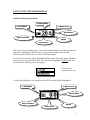
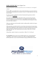
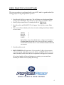
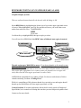
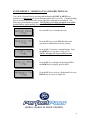
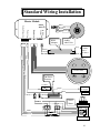
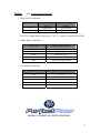
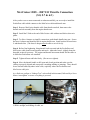
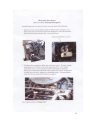
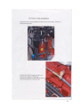
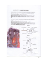
Stern Drive Service Manual
v. 6.5NG
October 2006
PerfectPass Control Systems Inc.
14 Trider Crescent
Dartmouth, NS
B2W 2R3
Phone: (902) 468-2150
Fax:
(902) 468-8837
Stern Drive Service Manual 6.5NG
Table of Contents
Page
Key Components
1
Navigating the Screen (Changing modes)
2
Common Problems
3
Appendix
-
Servo Motor Test
4
Linkage Test
5
Servo Phase Test
6
RPM Mode Testing (On Water or Fake A Lake)
7
System Reset
8
Investigating Blown Fuse
9
Paddlewheel Troubleshooting
9
System Wiring Diagram
10
MerCruiser Install Tips
12, 13
Volvo Install Tips
14, 15
KEY COMPONENTS
The PerfectPass kit for this boat includes the following key components:
1. Master Module Control Box
2. In Dash Display Gauge
3. 12V Power Cable & RPM Cable
4. Servo Power Cable (Master Module to Servo Motor)
5. Servo Motor & throttle cable (Connected to engine)
6. Thru-hull Paddle Wheel Speed Transducer
(See full system wiring diagram on Page 10).
How PerfectPass Works
Through the in-dash display the driver sets the desired boat speed or engine RPM depending upon
which mode of operation the driver has selected. The master module computer calculates the
speed of the boat from the paddlewheel signal and the engine RPM from the engine tachometer
signal. The servo motor control cable is connected to the throttle arm of the engine, which allows
the servo motor to control the engine’s power. This control cable operates the throttle in
cooperation with the manual throttle cable so that both the driver and the servo motor are able to
change the engine output.
As the driver advances the throttle handle to bring the boat up to speed, the servo motor prepares
to take control, at the point where the boat speed or engine RPM has reached the desired level, the
system beeps to indicate it is beginning to control and the driver stops moving the throttle handle.
The servo motor adjusts the engine throttle as required to continuously maintain the set speed or
RPM. The driver is able to change the set speed or RPM while the system is engaged by simply
pressing the up or down keys for each ¼ mph change in speed or 25 RPM change desired. At any
time the driver may pull back on the manual throttle to slow the boat down, the PerfectPass
system immediately stops controlling the engine and the driver once again has full control.
Start Up Procedure
The Master Module is the heart of the system and requires a solid and continuous 12 volts before
the “relay” will allow the Intel Processor to start. Upon proper start up, the Dash Display will
become active and the servo motor will power up and perform an “auto- tighten” rotation check.
A great deal can be confirmed from visually watching this routine start up. If the key is moved to
the on position, the PerfectPass Display should become active & beep and servo motor is
powered. If you then spin the paddle wheel you should see a speed signal register on the
PerfectPass Display confirming proper operation.
1
NAVIGATING THE DASH DISPLAY
Wakeboard Mode (Speed Based)
2. Name/Mode
3. Menu Arrow
1. SETPOINT
Speed Base
Mode Indicator
Speed
Tachometer
There are two key operating modes. The main Wakeboard Mode is speed based from the
“thru hull” paddle wheel. In this mode you select a mph setting such as 20 mph.
The other mode is RPM, where you select an RPM set point.
To move between modes, simply highlight the Menu Arrow Icon in the upper right hand
part of the screen using the Menu Key. Once this Icon is highlighted, quickly press the
Up Key and the following screen will appear.
Use Menu Key to
highlight desired mode.
To select the RPM mode, you would press the UP Key when RPM is highlighted.
2. Menu Arrow
1. SETPOINT
Speed Base
Mode Indicator
Tachometer
Speed
2
COMMON PROBLEMS
Control Issues – Any complaint that the PerfectPass is surging or not holding speed
properly should lead you to a Servo Motor and Linkage Test. If the boat is in the
shop, run the boat in RPM Mode (See procedure on page 7 to confirm if the system
is mechanically working properly).
1.
Customer Complaint: System Surging / not holding speed
Action: Perform a Servo Motor Auto Tighten Test and Phase Test. Perform a
Linkage Test. (Pages 4, 5 &6).
These will confirm whether the servo motor & mechanical connection are OK.
Ideally, run the engine on a Fake A Lake in RPM mode. (See RPM Mode Testing
Page 7). Inspect paddlewheel for damage.
2.
Customer Complaint: System engages and controls, but boat speed all of sudden
slows right down to 5 or 6 miles per hour.
Action: A loose wire or crimp in the main servo motor power cable could cause
this. (See Servo Motor Test & Phase Test. Pages 4 & 6).
3.
Customer Complaint: No Speed Reading / Very Low Speed Reading
Action: Inspect paddle wheel speed sensor under boat to ensure it is not
damaged. If you spin paddle you should see at least 7 mph on screen.
If the speed reading is very low, perform a quick “System Reset” that will reestablish the calibration points. (See Page 8).
4.
Customer Complaint: LCD Screen on Display going black or characters upside
down
Action: Electrical interference from an outside source such as operating the
“trim” system can cause this. This can be solved by moving the PerfectPass
Display cable behind dash as far away from the other boat wiring (including trim
electrical) as possible.
5.
Customer Complaint: Hard to read LCD Display
Action: Press Menu & Up Key together to access “Contrast Adjustment”
6.
Customer Complaint: System beeps to confirm engagement, but system never
takes control.
Action: This means the Master Module is taking control, but the servo motor is
not responding. (See Servo Motor Test Page 4).
3
SERVO-MOTOR TEST (Auto-Tighten Test)
Each time PerfectPass is powered, the position of servo is checked by an “auto tighten”
rotation.
With key OFF, you should be able to easily turn the black knob on servomotor shaft. (If
you cannot turn the knob then the servomotor is seized). The black knob moves the shaft
on servo motor.
To check servomotor, turn knob in clockwise direction until snug, then turn it back
counterclockwise one full turn.
Now turn key ON which will power PerfectPass. When you hear the beep from the
PerfectPass Display the servo will perform its “auto tighten” function and wind in the
servo in a clockwise direction by ¾ of a turn. (Gently hold the knob during this rotation
test to add a little resistance).
If the servo winds in the cable smoothly, then this would generally confirm the wiring to
servomotor is good.
If the motor does not wind in the cable or it just vibrates, then an electrical connection or
crimp is bad. Unplug the two white connectors at servomotor and inspect the wires going
into the connectors. Gently pull on each wire to see if one is loose or not securely in
crimp. Also, check the wires at plug in the gray servo power cable where it exits the
Master Module.
If the problem cannot be located, you can perform a “Phase Test”. (See Page 6).
New Installation: If the system was just installed and the servo will not perform the
“auto tighten”, check to make sure the gray servo cable is not plugged into Master
Module upside down. Tips on connector should be facing up towards label on module.
4
LINKAGE TEST
This test should confirm whether the PerfectPass throttle cable & linkage connection is
properly working.
With key OFF, push the manual throttle to 3/4 open position. Now take black knob on
servo and slowly turn the knob in a counterclockwise direction, and then in a clockwise
direction.
As you rotate the knob back & forth, you should see the throttle lever on engine opening
& closing very smoothly with each step of the motor. As you turn the knob
counterclockwise, which lets out cable, the throttle will close back towards neutral. When
you rotate it clockwise the throttle will open.
As you rotate the knob back and forth (slowly and quickly), the throttle should open &
close very smoothly and the brass L Adapter at linkage should be rotating as well to
follow cable. At no point should the throttle cable catch, hook or come into interference
with any part that could disrupt the cable movement.
At no point should you see “slack” or loose Dacron cord on the servo shaft unless the
throttle lever on engine is back to full neutral stop.
Make sure there are no bends in the inner PerfectPass stainless cable where it connects to
throttle lever (last two inches at brass L adapter). The PerfectPass cable and the boat
throttle cable must seamlessly join together.
If the cable is rubbing against a decorative engine cover, fuel rail, motor box etc., or does
not align properly as cables come together at neutral, adjust servomotor and cable to
improve alignment. Many plastic decorative engine shrouds can cause this problem.
Remove temporarily and run boat if you suspect this could be a problem.
Final Test: With key OFF, push manual throttle to full open position. Watch PerfectPass
throttle cable to ensure it can move freely without binding or interference.
Throttle Return Spring – PerfectPass relies on the engine’s throttle return spring for
proper operation. PerfectPass turns the servo counterclockwise to slow engine, at which
point the arm is pulled back by the return spring. An engine without a spring (or very
weak spring) may speed past the set point and never settle back.
5
SERVO PHASE TEST 6.5NG SOFTWARE
This test procedure is performed with control ON, and is a good method for
testing proper wiring & operation of servo.
1. Press Menu & Up Keys at same time. This will bring you to background Menu
starting with CONTRAST. Press Menu key until you get to “DEVICE TEST”
2. Press Up Key to enter Device Test and you will see: SERVO ON
SERVO OFF
3. Press Menu Key and PHASE TEST will appear. Press Up Key to enter Phase
Test.
4. The screen will now identify each color wire in the cabling from Master Module
to servo motor:
GREEN
BLACK
BROWN
WHITE
.3
.3
.3
.3
Each of these wire colors should show a voltage level of about .3.
If a wire shows 0, then that color wire does not have continuity
and should be checked where it exits the Master Module and at the
servo motor.
5. Press Menu Key to exit.
6. ROTATE SERVO will appear next. If you press the Up Key the servo motor
will rotate back & forth until you press the Up Key to RESET SERVO. If servo
rotates smoothly back & forth, then servo operation would appear to be normal.
(If you have handle well forward during servo rotation, you can watch how
smoothly the throttle arm is opening and closing).
6
RPM MODE TESTING (ON WATER OR FAKE A LAKE)
Graphics Display Systems
This test confirms that mechanically the throttle cable & linkage is OK.
Go to RPM Mode by highlighting the Menu Arrow Icon in the upper right hand corner
of screen. When highlighted, press Up Key and this will move you to the other event
modes from which to select. WAKEBOARD
RPM
SLALOM
Use Menu Key to highlight RPM, then press up key to select.
You will now be in RPM Mode. Set RPM Value at 2400 and start engine in neutral.
2. Menu Arrow
1. SETPOINT
Speed Base
Mode Indicator
Speed
Tachometer
Speed will read O when
on a hose.
Throttle engine up to 3000 RPM or more. (If you do not throttle up far enough system
will surge up & down) Does it lock in and hold at 2400 RPM ?
(If you were to watch black knob on servo, the servo motor will turn counter clockwise to
slow engine after engagement. As it counter rotates, the throttle lever on engine will
slowly move back & slow engine speed until it reaches 2400)
In RPM Mode it should hold very tightly at 2400, if it does not settle down to 2400 or
controls erratically, Perform a “Linkage Test”.
While it is controlling at 2400, advance throttle lever an inch or two and engine should
throttle up, but PerfectPass will slow engine speed back to 2400.
Control Problem- If customer indicated it did not hold a steady speed in Wakeboard
Speed Mode, but it controls well during this test then you must inspect the paddle wheel.
Contact us for more details.
7
SYSTEM RESET - VERSION 6.5 NG (GRAPHIC DISPLAY)
You can do a System Reset by pressing and holding the ON/OFF & MENU keys
together as you power-up the system (turning ignition ON or to ACC). Continue holding
keys as the skier moves across the screen and system information is displayed. The
following screen should now appear. NOTE if this screen does not appear turn off the
ignition and try again, making sure to hold ON/OFF and MENU keys.
Press the UP key to continue the reset
Press the UP key to reset RPM Baselines and
speedometer calibrations to factory settings
Press the UP if you have a standard engine. Press
the DOWN key if you have a 6.0L or 8.1L
NOTE: Message will vary on OEM versions
Press the UP key to display the speed in MPH or
the DOWN key to display speed in KPH
Press the UP key to reset as a Wakeboard Pro or the
DOWN key to reset as a Digital Pro
8
INVESTIGATING BLOWN FUSE
Fuse - 1.25” 5 AMP
Typically, a fuse will only blow if there is a short in the red wire found within the gray servo
power cable, which carries 12 volts from the Master Module to the servo motor.
Closely inspect the servo motor power cable connector both at the Master Module end and at the
servo motor and gold resistor end located at the engine. If the red wire is split, frayed, etc, it
could be the cause of the “grounding out” of this 12 volt supply causing the fuse to blow.
Pinching or crushing of this cable could also cause a “ground out” of the 12 volt supply and blow
the fuse.
If after careful inspection of this cable, the problem has not been found then the following
procedure can be followed to help identify the source of the blown fuse:
Step.1. With the key off, unplug all plugs from the Master Module, except the Display.
Step.2. Turn key on and go to the Battery Voltage reading on the PerfectPass Display. (Press
Menu & Up Keys together, then press the Menu key. Make a note of the battery voltage
displayed).
Step.3 Now plug in the paddle wheel plug. The displayed voltage should not change.
Step.4 Now plug in servo power cable with the servo motor connections intact. The voltage
reading with a good cable should drop about 0.3 volts. [A significant voltage drop (1 volt
or more) would confirm a problem with the servo motor or cable].
Step.5 You can also perform this test with the servo motor and resistor unplugged. This would
test the servo power cable independently, if no problem is found with the cable alone,
then plugging in the servo motor will help identify the location of the problem.
PADDLEWHEEL TROUBLESHOOTING
If your system works very well and controls smoothly in the rpm mode, but surges and hunts in
the speed based mote, it is likely a paddlewheel related problem.
1.
2.
3.
4.
5.
6.
Does the paddlewheel impeller spin freely? (if not, change impeller).
Is the paddlewheel housing under the hull pointing straight forward. The arrow on the
housing must be pointing straight ahead.
Is the impeller installed in the assembly in the correct direction?
Is the paddle insert fully and properly set in the housing?
Are the two side shields bent?
Is the paddlewheel installed in the correct location? Call for details on your boat model.
It cannot be installed directly behind a strake, water intake, etc. which could disturb the
flow of water.
9
Standard Wiring Installation
Master Module
White
Bare
Brown
Green
Red
RPM
Sensor
Display
Power
Servo Motor
Paddle
Wheel
RPM
Adapter
Paddlewheel Unit
Grey
Black
Green
Red
Black
To RPM
Source
See Note 1
Black
Green
Purple
Brown
Black White
ON/OFF
MENU
Perfect Pass
Red
5Ω Power
Resistor
5 A Fuse
Switched
12V Supply
Purple
Black
Red
Ground
Red
Red
Red
Red
Servo
Motor
White
Black
Brown
Green
10
Notes:
from ‘Standard Wiring Diagram’
1. RPM Source Connection
Wire Color
Standard Signal
Input
Low Level Signal
Input*
Grey
To RPM Signal
Not Connected
Black
To Ground
To RPM Signal
*Low Level Signal Inputs are given by LTR, LT-1, and LS1 engines prior to 2002
2. Paddle Wheel Cable Data
Wire Color
Signal Carried by Wire
Red
+12 V
Green
Speed Signal
Brown
Temperature Signal
Bare
Speed Signal Ground
White
Temperature Signal Ground
3. Servo Motor Cable Data
Wire Color
Signal Carried by Wire
Red
+12 V
White
White Motor Phase
Brown
Brown Motor Phase
Black
Black Motor Phase
Green
Green Motor Phase
11
MerCruiser 2005 – 2007 I/O Throttle Connection
(5.0, 5.7 & 6.2 )
After you have servo motor connected to exhaust manifold, you are ready to install the
PerfectPass cable which connects to the MerCruiser cable and throttle arm.
Step 1. Remove MerCruiser throttle cable from throttle arm bolt, then remove the
throttle arm bolt assembly from the engine throttle arm.
Step 2. Install the U Bolt to the end of MerCruiser cable with nut and bolt as shown in
photo.
Step 3. To allow clearance to simplify connection, push throttle handle into gear. Secure
the brass L adapter and shoulder bolt to engine throttle arm. Install washer between brass
L and throttle arm. (The brass L adapter must be able to swivel freely).
Step 4. Before final tightening, bring throttle back to neutral and the PerfectPass and
MerCruiser cable should come together and touch. Adjust the brass L slightly along the
threaded section if necessary. The engine and throttle movement should feel the same as
it did before PerfectPass was installed.
Step 5. Tighten all nuts and bolts firmly. (Do not over tighten).
Step 6. Move the throttle handle to full open and closed position and make sure the
cabling is properly aligned and at no point is anything rubbing or jamming. There should
be no extreme bends anywhere in the cable, especially where the PerfectPass and
MerCruiser cable join.
As a final test, perform a “Linkage Test” as described in this manual, followed by a Servo
Motor “auto tighten” test once everything is powered.
Image shows proper alignment in neutral.
U Bolt is straight, no bending of cable, etc.
12
13
14
15