1
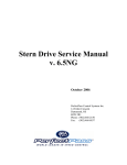
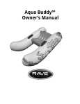
PerfectPass
Correct Craft
General Information/Troubleshooting
Guide
February 2005
(902) 468-2150
1
Table of Contents
Page
Number
List of Major Components
1
System Schematic/Wiring Detail
2
How PerfectPass Works
4
Thru-Hull Paddlewheel
5
Installing New Impellar
5
Servo Motor Operation
6
Servo Motor Testing
6
Quick Reference Trouble Shooting Guide
7
Trouble Shooting Q & A
8
Linkage Test
10
System Reset
11
Paddlewheel Trouble Shooting
11
Switching Between WakeboardPro and DigitalPro
11
KDW / NN Wakeboard Settings
12
Investigating Blown Fuse
12
Tank Testing – Fake A Lake
13
Excalibur Installation Photo
14
GT-40 Installation Photo
15
2
1. Master Control Module
2. Servo Motor Power Cable (from Master Module to Servo Motor)
3. Servo Motor & Throttle Cable
4. In-Dash Display Gauge
5. Thru Hull Paddle Wheel Speed Sensor
6. Power Cable & RPM Cable (Both connected to back of tachometer to provide 12
volts to power system as well as provide rpm signal).
See wiring schematic on next page.
3
Standard Wiring Installation
Master Module
White
Bare
Brown
Green
Red
RPM
Sensor
Display
Power
Servo Motor
Paddle
Wheel
RPM
Adapter
Servo
Motor
Grey
Black
Green
Red
Black
To RPM
Source
See Note 1
Black
Green
Purple
Brown
Black White
ON/OFF
MENU
Perfect Pass
Red
5Ω Power
Resistor
5 A Fuse
Switched
12V Supply
Purple
Black
Red
Ground
Red
Red
Red
Red
Servo
Motor
White
Black
Brown
Green
4
Notes:
from ‘Standard Wiring Diagram’
1. RPM Source Connection
Wire Color
Standard Signal Input
Grey
To RPM Signal (SND POST ON TACH)
Black
To Ground (GRD POST ON TACH)
2. Paddle Wheel Cable Data
Wire Color
Signal Carried by Wire
Red
+12 V
Green
Speed Signal
Brown
Temperature Signal
Bare
Speed Signal Ground
White
Temperature Signal Ground
3. Servo Motor Cable Data
Wire Color
Signal Carried by Wire
Red
+12 V
White
White Motor Phase
Brown
Brown Motor Phase
Black
Black Motor Phase
Green
Green Motor Phase
5
How PerfectPass Works
Through the in-dash display the driver sets the desired boat speed or engine RPM
depending upon which mode of operation the driver has selected. The master module
computer calculates the speed of the boat from the paddlewheel signal and the engine
RPM from the engine tachometer signal. The servo motor control cable is connected to
the throttle arm of the engine, which allows the servo motor to control the engine’s
power. This control cable operates the throttle in cooperation with the manual throttle
cable so that both the driver and the servo motor are able to change the engine output.
As the driver advances the throttle handle to bring the boat up to speed, the servo motor
prepares to take control, at the point where the boat speed or engine RPM has reached the
desired level, the system beeps to indicate it is beginning to control and the driver stops
moving the throttle handle. The servo motor adjusts the engine throttle as required to
continuously maintain the set speed or RPM. The driver is able to change the set speed
or RPM while the system is engaged by simply pressing the up or down keys for each ¼
mph change in speed or 25 RPM change desired. At any time the driver may pull back
on the manual throttle to slow the boat down, the PerfectPass system immediately stops
controlling the engine and the driver once again has full control.
Start Up Procedure
The Master Module is the heart of the system and requires a solid and continuous 12 volts
before the “relay” will allow the Intel Processor to start. Upon proper start up, the Dash
Display will become active and the servo motor will power up and perform an “autotighten” rotation check.
A great deal can be confirmed from visually watching this routine start up. If the key is
moved to the on position, the PerfectPass Display should become active & beep and
servo motor is powered. If you then spin the paddle wheel you should see a speed signal
register on the PerfectPass Display confirming proper operation.
The WakeboardPro has two operating modes:
1.
Speed Based Wakeboard designed primarily for wakeboarding in the 15 – 25 mph
range. User sets a speed on the main screen.
[ WKB D 20.0 0.0 ]
set speed digital speedometer
2.
RPM Mode where the user sets an rpm value. Designed for higher speed use such
as open water skiing or cruising.
Set rpm
[ 2800 00 0.0 ]
tach
digital speedometer
6
Thru Hull Paddle Wheel
White
Bare
Brown
Green
Red
Red – 12-V Power
Bare – Ground
Green – Speed
White – Water Temp
Brown – Water Temp
The Thru Hull Paddle Wheel (Model ST300) is manufactured by AirMar Technologies.
Its primary purpose is to provide a digital speed signal to the PerfectPass Gauge. It also
has a water temperature probe built in which can be displayed on the PerfectPass gauge.
The paddle wheel impellar must be able to turn freely in order for an accurate signal to be
produced. It must be properly installed in an area of the hull where the water flowing
back over the paddle is clean and undisturbed. It must be installed facing straight ahead.
If any part of the paddle wheel or shaft becomes damaged or slightly bent, the speed
signal will not appear on the screen or will be inconsistent. The impellar can be quickly
changed.
The paddle wheel is designed to be most accurate at speeds under 35 mph. At high speeds
depending on trim position and hull dynamics, the speed displayed may not be accurate.
Wakeboarding is typically enjoyed at speeds in the 16 – 22 mph range. At higher speeds,
and for skiing, users will typically find the rpm mode smoother.
If the displayed speed on the PerfectPass gauge is incorrect, ( ie: the system indicates 20,
but actual speed is 22) this can be easily calibrated by pressing the Menu Key to enter
“Speedo Adjust” then press the down key to lower speed by 2 mph.
Changing Impellar – The life of the paddle wheel axle and bearing is designed for years of
trouble free operation. In the event of damage to the rotating paddle or axle, ideally the boat
should be removed from the water for inspection. (Clean debris if necessary.) If the paddle
requires replacement, remove large housing nut and pull paddle assembly out of housing.
(Note the direction of rotation of impellar so flat surfaces are toward bow as per arrow on
assembly). Press the axle out of position and install new one. You may wish to install new
“O rings” at this time as well. Re-insert paddle wheel assembly ensuring the unit is in the
“notch”. Re-install locking cap.
(If your digital speed readout is suddenly reading extremely low or not at all, check paddle
assembly).
7
Servo Motor
Red
Red
Red
Green
Brown
Black
Red
Red
White
Yellow
White
Black
Red
Green
Blue
LIN
Engineering
The 4 – Phase servo motor can make hundreds of adjustments per second to maintain the
correct speed. It is vitally important that the throttle cable has free movement and the
brass L Adapter (Volvo only) connecting the PerfectPass throttle cable to throttle arm can
swivel and rotate smoothly.
If a servo motor is not installed in the correct location, the throttle cable may have too
much of a bend or may jam against the engine cover which will cause improper
operation.
Anytime you suspect the system is not controlling properly, A Servomotor Test should be
performed as follows. If servo motor test is successful, perform a linkage test on page
10.
Servo Motor Test / Auto Tighten Test
Every time you return the boat to neutral when PerfectPass is on, the servo will wind in
the cable until snug in a clockwise direct. This is the normal starting point for the servo.
Each time you turn the key on or start the boat, PerfectPass becomes powered and the
servo will perform an “auto tighten” function and will attempt to wind in the cable to
confirm it is in normal position. (If in proper position, it will appear simply as a “click”,
“click”, “click”).
To check servo & servo power wire, with key off turn black knob on servo motor counter
clockwise ¾ of a turn. Now turn key on and black knob should turn clockwise about ¾ of
a turn as part of auto tighten. If it does, repeat procedure, except this time hold black
knob gently to apply some resistance to auto tighten. If it rotates with good strength then
it would appear servo & servo power cable are fine.
If it does not rotate or just vibrates, then a wiring phase coming to the servo may be loose
or broken. Inspect all wiring around servo. Pull both white plugs apart at servo & inspect
pins to ensure they are in place. Gently tug on each wire to ensure they are securely in
crimp. Check at Master Module where cable is connected.
If you cannot locate problem, contact PerfectPass.
Important Notes:
1. The gold resistor will run extremely hot. This is normal.
2. If system is new, make sure servo power cable is plugged into Master Module
correctly and not upside down. Tips on plug should point up towards label on
Module.
8
Quick Reference Trouble Shooting Guide
Problem
Possible Cause (Action)
Display does not power up.
Is display plugged into master module.
Check fuse. Check 12-volt power
source, ground to PerfectPass.
No speed reading.
Is paddle cable connected to master
module. Is paddle damaged. Does it
spin freely.
Not controlling well.
Not controlling at all.
Perform servo motor test, perform
linkage test.
System beeps to confirm engagement,
but continues past set speed and does not
control.
Perform servo motor test, linkage test
and return spring test.
Button on keypad does not work.
Unplug display connector at master
module and check pins.
Replace display.
System controls well in RPM mode, but
not smooth in speed mode.
Is speed mode setting 25 mph or less? Is
paddle wheel in good condition.
Paddlewheel impellar damaged.
Install new impellar kit available from
PerfectPass.
Displayed speed not correct. i.e. system
says 20, actual speed 22.
In Wakeboard mode, press menu to enter
“Speed Adjust”. Quickly press down
key and lower speed by 2 mph.
System disengages on its own and boat
slows.
Is manual throttle handle pulling back on
its own, if not perform servo motor test.
Blowing 5 amp fuse.
Inspect red wiring around servo motor
for a ground or short.
9
Troubleshooting Q & A.
1.
Condition:
In both Speed & RPM Mode the system beeps to engage, but speed never settles
in and hunts beyond & below target speed.
Solution:
It appears that the PerfectPass throttle cable does not have free movement and is
rubbing against engine cover or some other obstacle. A Linkage Test should be
performed.
2.
Condition:
System beeps to confirm engagement, but boat continues past set speed and never
locks in.
Solution:
Computer is attempting to control, but servo not responding. Perform Servo
Motor Test. (Servomotor could be seized).
3.
Condition:
System hunting in speed mode only. RPM Mode working perfectly.
Solution:
1.
Inspect paddle wheel for damage…does it spin very freely.
2.
Is paddle wheel fully seated in housing, is arrow pointing forward.
4.
Condition:
PerfectPass digital speed reading shows 22 mph, but GPS indicates boat speed is
actually 24 mph.
Solution:
Press menu key once and “Speedo Calibrate” will appear. Quickly press down
key several times and drop calibration speed by 2 mph. (Can be done in the shop
or on the water). Remember, the LCD screen simply shows the data from Master
Module so there is no reason to suspect the Display is a problem.
5.
Condition:
PerfectPass green light in display is on, but no data on screen.
Solution:
Check to see if servo motor is powered, if not then the system does not have
adequate voltage or is poorly grounded and will not start. (Measure voltage on
PerfectPass power cable, which should be in excess of 12v).
Note: When key is off, the black knob on servo turns very easily. When powered,
knob is stiff and is difficult to turn.
If servo is powered and performs auto tighten rotation but Display has no data,
then Display should be changed.
10
Troubleshooting Q & A. (Cont’d)
6.
Condition:
PerfectPass has no digital speed reading
Solution:
1.
Check Master Module to ensure paddle wheel cable is properly connected
and pins are in proper position and not bent.
2.
Does paddle spin freely.
3.
If all looks well, perform a “System Reset”
7.
Condition:
Up key on Display does not respond.
Solution:
Make sure all 10 pins on Master Module are in-line where display connects. If
connection is OK, key pad switch is faulty, return to PerfectPass for repair.
8.
Condition:
Boat speed drops and throttle handle must be pushed far down to get acceleration.
Solution:
Servo Motor is not holding and rotating properly usually due to a bad connection
at servo. See Servo Motor Test, page 6.
9.
Condition:
System is blowing the 5 amp fuse on 12v power cable.
Solution:
Generally caused by a short or “grounding” problem with the red 12v power
cable on servo motor. Closely inspect wiring particularly around gold resistor.
(Remember, resistor & servo will run very hot which is normal).
10.
Condition
Speed control sometimes disengages on its own.
Solution:
Is manual handle pulling back. Does “#” sign appear on screen?
11.
Condition
Customer ordered a DigitalPro, but on start up it say’s WakeboardPro.
Solution:
Switch software by holding Menu and Down keys together as you turn key on to
power system.
11
LINKAGE TEST
This test should confirm whether the PerfectPass throttle cable & linkage connection is
properly working.
With key OFF, push the manual throttle to 1/2 open position. Now take black knob on
servo and slowly turn the knob in a counterclockwise direction, and then in a clockwise
direction.
As you rotate the knob back & forth, you should see the throttle lever on engine opening
& closing very smoothly with each step of the motor. As you turn the knob
counterclockwise which lets out cable, the throttle will close back towards neutral. When
you rotate it clockwise the throttle will open.
As you rotate the knob back and forth (slowly and quickly), the throttle should open &
close very smoothly and the brass L Adapter at linkage should be rotating as well to
follow cable. At no point should the throttle cable catch, hook or come into interference
with any part that could disrupt the cable movement.
If the cable is rubbing against a decorative engine cover, fuel rail, motor box etc, adjust
servomotor and cable to improve alignment. Many plastic decorative engine shrouds can
cause this problem. Remove temporarily and run boat if you suspect this could be a
problem.
Final Test: With key OFF, push manual throttle to full open position. Watch PerfectPass
throttle cable to ensure it can move freely without binding or interference.
Boat Speeds Past Set Speed
If the system beeps to confirm engagement, but continues past set speed, perform a Servo
Motor Test and Linkage Test. If these tests indicate all is well, it could be a Throttle
Return Spring problem.
Throttle Return Spring: PerfectPass can open the throttle (by turning clockwise), but
relies on the engine return spring to close the throttle when the servo turns
counterclockwise. (The return spring is always applying pressure against the throttle
back towards the neutral position). If the servo turns counterclockwise to slow the boat,
but the throttle lever on engine does not move or moves very slowly, the return spring
could be weak, broken, etc.
If you feel the spring is weak or damaged, an external return spring can be added.
12
Resetting a Wakeboard Pro
Version 6.3/6.4/ 6.5
You can do a System Reset by pressing and holding the ON/OFF & MENU Keys
together as you turn key on to power system. Continue holding as the Perfect Pass
display goes through its normal start up procedure until [System Reset ^ = Yes] appears.
Press the UP key to continue the reset. It will then display [Reset RPM @ ^ = Yes].
Answer yes by pressing the UP key. Next on the display will be [Read in MPH ^ = Yes].
Answer yes by pressing the UP key. Next [Wakeboard Only ^ = Yes] will appear.
Answer yes, by pressing the UP key. For WakeboardPro, press Down for DigitalPro.
Paddle Wheel Troubleshooting
If your system works very well and controls smoothly in the rpm mode, but surges and
hunts in the speed based mode, it is likely a paddle wheel related problem.
1. Does the paddle wheel impeller spin freely? (If not, change impeller).
2. Is the paddle wheel housing under the hull pointing straight forward. The arrow
on the housing must be pointing straight ahead.
3. Is the impeller installed in the assembly in the correct direction?
4. Is the paddle insert fully and properly set in the housing?
5. Is the paddle wheel installed in the correct location? Call for details on your boat
model. It can not be installed directly behind a strake, water intake, etc. which
could disturb the flow of water.
6. Perform a System Reset. Press & hold the ON/OFF & MENU Keys together as
you power up the system. Continue holding until you see the System Reset
Prompt.
7. If it only surges when the boat is heavily loaded in a certain configuration, it may
be a location problem.
TEST – Drive boat in RPM mode at a value of 2800 RPM. When RPM is locked on,
watch PerfectPass digital speed reading. It should only be varying by one or 2 tenth’s. If
it is varying more than this, then the paddle signal to PerfectPass is not consistent.
Switching from WakeboardPro <> DigitalPro
The Master Module for both systems is identical and the software for both is stored
inside. If a system was set up incorrectly (ie: customer ordered a WakeboardPro but when
he turns it on it says DigitalPro) this can be easily changed.
Simply press & hold the Menu & Down Keys together as you turn the key on to power
system. Keep holding for a few seconds until you see “Servo Test ^ = Yes”. Press no or
down key to move into sub menu. When you see [ Wakeboard only ^ = Yes ] press up for
WakeboardPro or down for DigitalPro.
13
Adjusting KDW / NN
KDW
If you wish to change this control parameter, press OFF, then press the UP & DOWN
Keys together. You can then change the KDW using the up or down keys. Higher values
= more aggressive control response. Factory setting is 60. (Example: Heavily loaded
boats may need a higher value to maintain a steady, crisp pull. Try 100 – 150). After
adjustment, press MENU to process.
NN
This follows KDW and represents the filter factor of the paddle wheel. Typical values
(120 – 160). Higher values mean the system will sample more revolutions prior to
making a speed adjustment. If you feel the system should be “smoother”, try raising the
NN.
Investigating Blown Fuse
Fuse - 1.25” 5 AMP
Typically, a fuse will only blow if there is a short in the red wire found within the gray
servo power cable, which carries 12 volts from the Master Module to the servo motor.
Closely inspect the servo motor power cable connector both at the Master Module end
and at the servo motor and gold resistor end located at the engine. If the red wire is split,
frayed, etc, it could be the cause of the “grounding out” of this 12 volt supply causing the
fuse to blow.
Pinching or crushing of this cable could also cause a “ground out” of the 12 volt supply
and blow the fuse.
If after careful inspection of this cable, the problem has not been found then the following
procedure can be followed to help identify the source of the blown fuse:
Step.1. With the key off, unplug all plugs from the Master Module, except the Display.
Step.2. Turn key on and go to the Battery Voltage reading on the PerfectPass Display.
(Press Menu & Up Keys together, then press the Menu key. Make a note of the
battery voltage displayed).
Step.3 Now plug in the paddle wheel plug. The displayed voltage should not change.
Step.4 Now plug in servo power cable with the servo motor connections intact. The
voltage reading with a good cable should drop about 0.3 volts. [A significant
voltage drop (1 volt or more) would confirm a problem with the servo motor or
cable].
Step.5 You can also perform this test with the servo motor and resistor unplugged. This
would test the servo power cable independently, if no problem is found with the
cable alone, then plugging in the servo motor will help identify the location of the
problem.
14
PerfectPass Tank Testing
1. Move screen function to RPM Mode. Press Menu twice and [ Wkbd Spd ^ =
SLM ] will appear. Press up key twice to move to RPM Mode which will appear
as
2400
Set RPM
750
0.0
Tachometer
Actual Speed
2. With throttle locked in neutral, aggressively accelerate engine up and well beyond
2800. You will see the digital tachometer in center of screen. (You will feel a soft
spot in throttle as you accelerate…continue pushing throttle up and past 2800.)
When 2800 is reached you will hear a beep to confirm engagement and system
should start controlling. The digital tach should settle in and hold steady at about
2800.
3. As system is controlling at 2800, you can press throttle handle forward which will
cause engine to speed up briefly…it will then settle back at lock in again at 2800.
4. If you then bring throttle to neutral, servo motor will wind in cable clockwise to
its normal starting position.
5. With key on, spin paddle wheel and a digital speed signal will register on screen.
6. Throttle on boat should feel the same as a boat without PerfectPass, it should
smoothly go into and out of gear.
The key to a good installation is to ensure the PerfectPass throttle cable has a smooth
alignment to where it attaches to boat throttle cable. There should be no excessive bends
where cable could bind. Perform a Linkage Test if necessary.
15
1.
16
17