1
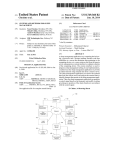
Official Speed Control of USA WaterSki & U.S. National’s
Official Speed Control of the Pro Tour, Masters, U.S. Open, Malibu Open
DigitalPro
By PerfectPass
User Manual
Version 6.5NG
June 2005
Information or assistance:
PerfectPass Control Systems Inc.
14 Trider Crescent
Burnside Industrial Park
Dartmouth, Nova Scotia
CANADA B3B 1R6
By phone
(902) 468-2150
By fax
(902) 468-8837
By email [email protected]
TABLE OF CONTENTS
Page Number
Section 1
- Getting Started
1
Initial Setup
Getting Familiar with PerfectPass
Changing Modes
Section 2
- Slalom Mode
Using Slalom Mode
RPM Based Slalom
Speed Based Slalom
Setting Baselines
Additional Information & Settings
Section 3
- Jump Mode
3
6
7
9
Using Jump Mode
Jump Driving
Additional Information & Settings
Section 4
- Trick Mode
14
Using Trick Mode
Trick Settings
Section 5
- RPM Mode
16
Section 6
- Wakeboard Mode
17
Using Wakeboard Mode
Wakeboard Settings
Section 7
- Calibrating PerfectPass Speedometer (Trick /Wakeboard)
19
Section 8
- Integrated Timing
20
Using integrated Timing
Placing Smart Timers
Placing Magnets
Section 9
- Magnet Test Mode
23
Section 10
- Addition Features
23
Screen Contrast
Name List
System Info
Control Parameters (CS / CR)
Override ON/OFF
Device Test
23
24
APPENDIX
All Ball Timing Information
Warning: PerfectPass highly recommends you become familiar with the operation of your new boat prior to using the speed control. (Leave in
OFF position). Once you are familiar and comfortable with the operation and handling of your boat, try the speed control in the different modes
without a skier to familiarize yourself with its operation. If you feel it is not working properly or have questions, leave in the OFF position and
contact PerfectPass or your dealer immediately.
USER’S GUIDE
Section 1. GETTING STARTED
INITIAL SETUP - The display will guide you through this set up. Read slowly and carefully.
Your new PerfectPass system must now complete a short set up procedure to familiarize itself with your
particular boat and engine. (This may have been performed by your dealer if factory installed)
Step (1)
Engine Selection. On some systems you will be asked to select the engine in your boat. It will appear as [5.7L
^ = Yes]. This means if you have standard engine, press UP. For optional big block 6L or 8.1L, press DOWN.
Step (2)
The display will now show [read in MPH ^ = Yes]. It is asking you if you would like the display to operate in
mph. If you do, confirm by pressing the UP key. If you want kph press the DOWN key. (We have selected
mph for illustration purposes)
Step (3)
[WAKEBOARDPRO ^=Y] The display will now ask if want the system to be a WakeboardPro or a 3-event
DigitalPro: For WakeboardPro Press UP, for DigitalPro press DOWN.
Step (4)
The display will now move into the Slalom mode, described in the next section.
GETTING FAMILIAR WITH PERFECTPASS
Turning System ON and OFF – All system functions require the PerfectPass control system to be powered up (ignition in
ON or Accessory position). The ON/OFF key turns the PerfectPass control ON or OFF. The system requires the boat to
be in neutral before turning the system ON or OFF. After pressing the ON/OFF key [IN NEUTRAL ^ =Yes] may appear
to remind the driver, and confirm the boat has been returned to neutral. When PerfectPass is OFF it will not engage. Any
time you operate your boat the system will be powered up, although it can be in the OFF mode. Every time you power up
PerfectPass it will return to the last event and speed that was used.
System ON
System OFF
Engaging System – With PerfectPass ON, the system will automatically engage once the SETPOINT is reached.
PerfectPass requires the driver to bring the boat up to and slightly past the SETPOINT before it will engage. When the
system engages it will sound an audible beep and the top line will become highlighted. In Slalom mode the screen appears
as follows:
Disengaging System – The PerfectPass system is unable to increase throttle position past the physical position of the
throttle handle. This important feature gives the driver the power to over ride the system at any point by simply pulling
back on the throttle. If the throttle handle is moved back past a point slower then where the system needs to be to control it
will disengage and boat will be under manual control.
Moving Around The Screen– The MENU key allows you to move around the screen to the various features. Any time
you scroll to the Menu Arrow Icon the system is prompting you to press either the UP or DOWN keys to select or
1
confirm an option. Pressing the DOWN key on the brings you into a calibration screen. The calibration screen varies
depending on the mode; the specifics of these screens will be covered within each mode description. Pressing the UP key
on the brings you into the Mode Select Screen.
MODE SELECT SCREEN
To change modes press the MENU key until the desired mode is highlighted. Press the UP key to go into the highlighted
mode. Press DOWN to go into the Mode’s background Setting Screens.
DOWN key for Mode settings
UP key to Select Highlighted Mode (Trick)
SUBMENU SCREEN
To enter the SUBMENU press the MENU and UP keys together, on any of the main mode screens.
Contrast – To adjust the darkness of the lettering on the screen you can change the contrast. This value can be adjusted
from 0-5 and is saved in the memory. The smaller the number, the brighter the screen will be in bright sun.
If you turn your boat on but cannot see the screen, press MENU & UP Keys together and adjust contrast Up or Down.
Name List – You can pull or enter a name from the name list here. The full description of the Name List is in Section 10
of the manual
System Info – General system information can be found here. The software version, engine selection, system voltage and
water temperature (not equipped on all boats) can be found here. See Section 10. ADDITIONAL FEATURES for more
information on this feature.
Device Test – This test allow you to test for proper control of the rope switches and for system troubleshooting. See
Section 10.
2
Section 2.
SLALOM MODE
USING SLALOM MODE
The Slalom mode is designed to give a skier an optimum and consistent pull through a Slalom course while producing
perfect timing passes. This section covers the various Slalom Modes within the PerfectPass system.
The main RPM based Slalom (36 mph – 24.9 mph) screen appears as follows:
2. Name/Mode/Crew
1. RPM Adjust
3. Menu Arrow
8. KX (Pull)
4. Speed/SETPOINT
7. PX (Rope)
6. Skier Weight
5. Course Times
Tachometer
As you press the MENU key you will move around the circle following the numbers above.
1.
RPM Adjust
This value directly adjusts the RPM/Speed value the system is trying to hold. If a time is fast or slow, you can
enter an RPM value for the next pass. Example: A time was a little fast and PerfectPass suggested “-20 RPM”.
Enter –20 on RPM Adjust. You may also use this in a headwind/tailwind situation.
2.
Name/Mode/Crew Weight
This section of the screen displays either the Mode, Slalom or a Skier’s Name pulled from the Name List.
Press UP key to access the Name List:
Name List is discussed in Section 10.
Press DOWN key to access the Crew Weight
Enter the Crew Weight in pounds using the
UP and DOWN keys. Press the MENU
key to confirm and continue.
3.
Menu Arrow
Press UP key to change modes or mode settings:
Change between modes using Menu Key.
3
Press DOWN key to Calibrate system:
The calibration screen is described
below in this section on Page 6.
4.
Speed/SETPOINT
The speed readout will turn into the SETPOINT when the engine is below 1500 RPM or the Speed/SETPOINT is
highlighted. When this is highlighted the metric conversion will appear in this area of the screen.
Press UP or DOWN keys to select desired SETPOINT:
5.
Course Times
This section of the screen displays the timing information from the last pass. As well as the suggested RPM
adjustment based on the times. These screens will scroll automatically at the end of each pass. The result of this
check is shown to the right of the times as shown below.
Tolerance Indicator
= Good Times
= Slow Times
= Fast Times
Full Course Error and Time
1st and 2nd Segment
1st and 2nd Segment Errors
Suggested RPM Adjust
With the times highlighted on the screen you can press the DOWN key to view the All Buoy Timing information.
ABT
All buoy times are displayed on one
screen with full course error and full
course time at the top. Press any key to
return to main screen.
4
6.
Skier Wight
To enter or adjust skier weight simply highlight this section of the screen and press the UP or DOWN keys to
make adjustments. The skier weight is entered in pounds, i.e. the above example shows a skier with a weight of
135 pounds. The skier weight is required so the PerfectPass system can apply the correct amount of RPM to
compensate for their pull. ( 1 pound = 1 RPM).
7.
PX (Rope Switch Setting)
Factory setting is 0, which is the off position (typical values range from 5 – 10). If the optional Slalom Switch is
used, this is the percentage of skier weight which is applied during each pull (i.e. A value of 10 would apply 20
rpm to a 200 pound skier). A value of 0 means no pull from the switch.
8.
KX (Throttle Response)
The KX value represents the throttle control response of the system. Under the current rules, a skier is encouraged
to use the factory settings or normal (represented by an “n” on the screen), but has the option for a higher more
immediate throttle response setting (+ or ++). As well they have the option for a lower KX (-).
Tips:
(1)
(2)
A shortcut to skier weight in Slalom Mode … press and hold MENU Key.
Crew Weight Calculator – When crew weight is on screen, press UP and DOWN
Keys together.
5
SLALOM CALIBRATION / SETTING BASELINES
(Your new system must be calibrated for accuracy)
4. Menu Arrow
1. Quick Calibrate
3. Baseline
2. SETPOINT
RPM Adjust
Course Time
Tachometer
Your system must be calibrated for accuracy in a course. This is often called setting Baseline RPM Values. In slalom
mode (without a skier) you must complete a timed slalom pass at each official speed you intend to use.
This must be done in a course using magnets and Mag Sensor or a PerfectPass Hand Timer. Once calibrated, these new
settings will be maintained in the system memory.
Step 1. In Slalom Mode, enter accurate Crew Weight, set Skier Weight to 0 and RPM Adjust to 0.
Step 2. Set speed (ex: 34.2) and engage system prior to course.
Step 3. Mag Sensor will trigger at entrance gate, ball 3 gate and exit gate. (Alternatively, if using Hand Timer push
button at same gate locations).
Step 4. Stop boat, highlight
Key and press Down to access “Quick Calibrate”. Press Up Key to confirm Quick
Calibration request. System will confirm “Baseline and Speedometer Calibrated”.
Step 5. After system confirms calibration at 34.2, change speed and repeat procedure.
23 MPH AND LOWER
As you calibrate the various slalom speeds, you will note that 23 mph and lower are speed based. After you do a Quick
Calibrate at 23 mph, you will be asked to perform a “Master Recal”. A yes to “Master Recalibrate” will automatically
calibrate all other “under 23 mph” slalom speeds.
(These under 23 mph speeds can be timed and calibrated independently for greater accuracy if desired).
TOWING A SKIER (The Basics)
Step 1. Enter Crew Weight, Enter Speed and Skier Weight.
Step 2. Pull skier up and engage system prior to course. (You will hear an audible beep).
Step 3. As you exit course review times on screen. If time was not perfect, the system will show an rpm suggested
change. I.e. “+20 ADJUST”. You should enter an RPM Adjust value or 20 on main screen for next pass. This will speed
up boat by 20 RPM. You may also use this feature in a headwind / tailwind situation.
6
ADDITIONAL SLALOM SETTINGS
Additional Slalom Settings are accessed by pressing the UP key on the Main Slalom Screen with the highlighted. Then
press the DOWN key when SLALOM is highlighted on the Mode Select Screen. The first two options can be accessed
from the Main Slalom Screen as described above as well as here in the Slalom Settings Screen.
Crew Weight – This setting can also be accessed on the main Slalom Screen as mentioned above on Page 3 or through
the Slalom Settings screen. This value should be set to represent the total Crew Weight in pounds in the boat. It is
essential this value be properly setup to ensure you get good times.
Crew Weight Calculator - The system will add the weight of up to 3 individual crewmembers. Simply go to
“Crew Adj” on the list, then press the DOWN and UP keys together, enter the weight of crew member #1, press
MENU and do the same for crew member #2. The system will total the weight automatically.
Calibrate – Press the UP key to enter the Baseline Calibration screen. This can also be accessed by pressing the DOWN
key with the highlighted on the Main Slalom Screen. To check baselines, complete a timing pass and then go to this
calibrate option. Press Up to enter Calibration Screen and then Up on Quick Calibrate to confirm calibration.
SSB (Second Segment Balance) - The percentage of skier value driven RPM that is removed during the second
segment to maintain an ideal time in slalom.
Example: If your 2nd segment is running a little on the fast side relative to the first segment time, you would raise
the SSB. The higher the value, the more RPM removed from the boat speed in the 2nd. Typical value is about 10.
RPM OFFSET – Press the UP key on this feature to view and edit the 3 Offset values, 36, 34.2 and LWR. The lower
(LWR) is used for all slower speeds. If you are finding that you are continually running less (or more) than a skiers weight
to achieve a good time, you can enter an rpm offset value. The OFFSET value is only applied when a skier weight is
entered. With a zero skier weight the OFFSET value has no effect.
Example: On a typical boat with a skier’s actual weight entered, you have to run 25 less rpm to achieve an
accurate time. If you are consistently seeing this, you can enter an offset rpm value (i.e.: -25) and the system will
allow you to run all other values as you normally would.
The offset value is independently set for 36.0, 34.2 and speeds 32.3-24.9 (LWR).
RPM Offsets
WT (Wait Time) - For tournament use to provide each skier the same wait time between passes. The number of seconds
between passes (i.e. 40 seconds). Starts timing as boat exits the course. Two short beeps are indicated with 10 seconds left,
followed by three long beeps when time is up.
Previous Times – To reload the previous times simply highlight this item and press the UP key. The full course and
segment times can be viewed from the Main Slalom Screen. The ABT’s can be viewed by pressing the DOWN key with
the Timing Information highlighted on the Main Slalom Screen.
7
ADDITIONAL SLALOM INFORMATION
Digital Speed Readout – The digital speedometer on the screen is for information only in RPM based Slalom. If you
feel it is not reading accurately, go into Quick Calibrate feature after running any timed pass and press the UP key to
recalibrate the speedometer.
Setting Baselines / Calibrating Speedometer without a Course – If you do not have the benefit of a course, you
can manually set baselines and calibrate the speedometer. This must be done at each slalom speed and you will require an
accurate boat speedometer or GPS.
Example: Starting at 36 mph, you engage system and note actual speed on the GPS is 35. Go into the Baseline
Calibration screen and raise the RPM Baseline about 100 rpm. This will speed up the boat to about 36 (100 rpm =
1 MPH). If speed is now accurate, the final step is to calibrate digital speedometer. Note the digital speed readout
and if it is reading 37, go into Speedometer Calibration Screen. Now press the DOWN key and lower
speedometer calibration by one mph. Run boat again to confirm accuracy. Once the baseline and calibration is set,
it will be saved within the system memory. Now change speed to 34.2 and repeat. All speeds you plan to use must
be done.
More Throttle – If you see the replace the on the Main Slalom Screen, the system is indicating it needs more
manual throttle in order to maintain the speed. In this case just move the manual throttle forward a little.
Comment [AA1]: This should be
mentioned in a more general portion of
the manual
Smart Timer False Triggered - The Smart Timer is sensitive and will false trigger outside the course on waves, etc.
To avoid false triggering, always slow the boat slightly to disengage the system after exiting the course between passes.
The system will not false trigger if it is not engaged. (In the event the Timer does trigger before the course, press the UP
key to reset Timer).
CR – Control Setting - The “CR” value can be adjusted to improve engagement, lock in and control. (See page 23 for
details). Recommended values: 2005 MasterCraft 1600
2006 MasterCraft 1950
Optional Slalom Switch - If you have a Slalom Switch, refer to detailed instructions sent with switch. The switch is
beneficial to “short line skiers”. For full details, please contact PerfectPass, or log on to www.perfectpass.com.
8
Section 3. JUMP MODE
USING JUMP MODE
WARNING: (Timing must be used in Jump mode and a proper two segment jump course is required for system to work
properly. Do not use PerfectPass in Jump mode without a proper course, integrated timing and experienced operator.
Because the counter cut pull and cut to the ramp are different, you must have timing activated and running as the boat
heads towards the ramp.
The Jump mode is RPM based and therefore baseline values must be established just as in Slalom mode. Setting the jump
baseline values must be done in a proper two segment jump course. Jump Letter must be set at A for this process.
The Jump mode main screen will appear as follows:
2. Name/Mode/Crew/
New Jumper
1. RPM Adjust
3. Menu Arrow
8. S2 Fine
4. Speed/SETPOINT
7. S2 Percent
6. Jump Letter
1.
5. Course Times
Tachometer
RPM Adjust
RPM adjust allows the driver to increase or decrease the overall times (1st & 2ng segment) by putting in a positive
or negative RPM adjustment.
Example: If the times are running consistently slow on both segments, you could add a value such as +20 rpm and
the speed will be increased. You may wish to do this for a particular jumper (a heavy puller) or for a number of
jumpers if the times are drifting in a certain direction
2.
Name/Mode/Crew/New Jumper
This section of the screen displays either the Mode Name or a Skier’s Name pulled from the Name List.
Press UP key to access the Name List:
Name List is discussed in Section 10.
Press DOWN key to access the New Jumper and Crew Weight
Press the UP key to enter a new jumper or
DOWN key to enter or edit the crew
weight. New Jumper is covered below.
9
Enter the Crew Weight in pounds using the
UP and DOWN keys. Press the MENU
key to confirm and continue.
3.
Menu Arrow
Press UP key to change modes or mode settings:
This allows you to change modes and
mode settings. The Additional Jump
Settings will be discussed below.
Press DOWN key to Calibrate system:
The calibration screen is described
below in this section.
4.
Speed/SETPOINT
The speed readout will turn into the SETPOINT when the engine is below 1500 RPM or the Speed/SETPOINT is
highlighted. When this is highlighted the metric conversion will appear in this area of the screen.
Press UP or DOWN keys to select desired SETPOINT.
5.
Course Times
This section of the screen displays the timing information from the last pass If Jump Letter is set to A and RTB,
the second segment error from Return to Baseline will be displayed after segment errors as seen below:
Tolerance Indicator
= Good Times
= Slow Times
= Fast Times
1st and 2nd Segment
1st and 2nd Segment Errors
2nd Segment Error
from Return to
Baseline Times
10
6.
Jump Letter
The Jump Letter is a combination of Jumper Weight, Jumper Distance and ability. . This Jump Letter represents
how much throttle will be applied once the Rope Switch is closed as the skier pulls. The higher the Jump Letter
selected the more aggressive the pull will be. If you are unsure what Jump Letter you should use then start by
using the ‘New Jumper’ feature as described below. This will automatically generate a Jump Letter based on your
weight and distance.
7.
Second Segment Percent (S2%)
This is a percent of the Jump Letter RPM that is applied once the boat enters the 2nd segment. Under IWSF and
AWSA rules, the boat is permitted to speed up in the 2nd segment. The higher the number, the more the boat will
accelerate. A typically value for S2% is +60, the higher the value, the faster the 2nd segment.
Example: If the 1st segment times are good, but the 2nd is a little slow, you would raise the number.
S2 RTB – Works similar to S2%. Used when “Return to Baseline” is selected. Only applicable if skiers are
activating switch and use a Jump Letter of J or higher.
8.
Second Segment Fine Adjust (S2 Fine)
This adjustment allows the driver to effectively fine adjust the 2nd segment only. It comes set at 0, which means a
neutral effect. A number such as 30 would increase the 2nd segment by 30 rpm. Higher number speeds up the
second segment. If skier does not trigger switch or has a letter less than J, S2 fine should be used to speed up
second segment.
Example: A jumper that does not cut and does not fully activate the switch may require extra rpm in the
2nd segment to keep the 2nd segment in tolerance. (In this case, S2 Fine is more effective than S2%).
Entering a New Jumper – To enter a new jumper highlight the NAME/MODE/CREW/NEW JUMPER section of the
screen and press the DOWN key. Then press the UP key to confirm you would like to enter a New Jumper.
You will be asked to enter and answer the following information after which a Jump Letter will be calculated for you and
displayed on the main screen. Move to the next selection by pressing MENU.
Select desired SETPOINT
Enter jumper weight in pounds
Enter typical jumping distance in feet
Toggles between Fast Second Segment
and Return to Baseline
to the right of the Jump Letter.
Return to Baseline (RTB) – If you selected Return to Baseline the screen will show
When RTB is selected the boat speed will immediately go to the baseline value as boat enters the second segment. If you
have a skier using the switch with a value of J or higher, you can enter an S2 value which is a % of switch driven RPM. A
setting above 0 will speed up boat in second segment if required to balance times. (This is similar to S2% used when
Faster 2nd Segment is selected).
Fast 2nd Segment – If you selected to run the fast 2nd segment, the screen will show
Comment [AA2]: Same thing here I
need a leason on how this workds
to the right of the Jump Letter.
Calibrating RPM Baselines - You can set RPM Baseline values for all of the official jump speeds (28, 29.8, 31.7, 33.6,
and 35.4) or just the ones you use regularly. Let us assume you wish to set up 33.6 mph (54 kph). Enter the SETPOINT
of 33.6 mph by pressing the MENU key until the ‘Speed/SETPOINT’ section of the screen is highlighted, then adjust the
SETPOINT to 33.6 = 54K. Set the Jump Letter to A. Now bring the boat smoothly up to the SETPOINT to engage the
system. (The system engages as soon as the default RPM Baseline value is reached, the NAME/MODE section will become
highlighted, and an audible beep will sound). Enter the jump course and time both segments. As you exit the course the
11
times will be displayed and then the difference from actuals. The display screen will show the 33.6 mph times. The jump
letter is set at A, RTB (return to baseline times are used). An example of this is shown in JUMP TIMING screens shown
earlier in this section.
If the times are not in tolerance or close to actuals then the RPM Baseline values will require adjustment. The easiest way
to do this in Jump mode is to go to Quick Recalibrate by pressing the DOWN key with the highlighted. This will bring
you to the Calibration screen as seen below.
4. Menu Arrow
1. Quick Calibrate
2. SETPOINT
3. Baseline
RPM Adjust
Course Time
Tachometer
Press the UP key on the Quick Calibrate message to recalibrate the baseline based on the times recorded from the last pass.
In this example it is suggesting your RPM Baseline should be increased by 135 rpm. When you perform a Quick Calibrate
the suggested adjust of 135 will be added to the baseline and saved in memory. The system will also calibrate the digital
speedometer if the times are with in the “OK” tolerance.
Now engage system and time boat again. If the times are still not close enough, repeat above steps until accurate. If you
wish to set up RPM Baseline values for other speeds (i.e. 31.7 mph), change the SETPOINT and repeat the above steps.
JUMP DRIVING
WARNING – Using the Jump mode with Jump Switch is for experienced drivers and skiers only. Please read carefully prior to
operating. The pull is very aggressive and designed for tournament water skiers only. You MUST have integrated timing and a proper
jump course for system to operate properly.
Assuming the RPM Baseline values have been accurately set, you are now ready to tow skiers.
First enter your Jump Letter or enter a “New Jumper” as explained above. The Jump Letter can be changed by pressing the
UP or DOWN keys with the Jump Letter highlighted on the screen.
The key to a good pull and good times is to get the correct Jump Letter. If the pull to the ramp is solid and the first
segment time is good, you know the Jump Letter is OK. If the time on the 1st segment was slow, you will require a higher
letter on the next pass and vice versa. (Once engaged, push handle to full open position to allow PerfectPass room to
throttle up when pulling long distance jumpers).
If the first segment time was good, but the 2nd was slow, raise the S2%.
Important Note: If the timer is triggered prior to entering the course, it must be reset by pressing the UP key. Failure to
reset will result in an improper pull to the ramp.
ADDITIONAL SETTINGS
Additional Jump Settings are accessed by pressing the UP key on the Main Slalom Screen with the highlighted. Then
press the DOWN key when JUMP is highlighted on the Mode Select Screen. The first three options can be accessed from
the Main Slalom Screen as described above as well as in the Jump Settings Screen.
12
Crew Weight – This setting can also be accessed on the main Slalom Screen as mentioned above or through the Jump
Settings screen. This value should be set to represent the total Crew Weight in pounds in the boat. It is essential this value
be properly setup to ensure you get good times.
Crew Weight Calculator - The system will add the weight of up to 3 individual crewmembers. Simply go to
“Crew Adj” on the list, then press the DOWN and UP keys together, enter the weight of crew member #1, press
MENU and do the same for crew member #2. The system will total the weight automatically.
Calibrate – Press the UP key to enter the Baseline Calibration screen. This can also be accessed by pressing the DOWN
key with the highlighted on the Main Jump Screen.
New Jumper – Details for entering a new jumper are outlined above. This should be used when unsure what Jump Letter
to select.
CT (Counter Cut Time) - The maximum length of time the system will throttle once the skier pulls and closes the switch
on the counter cut. Example: a value of 175 is 1.75 seconds and may be used in a tail wind. In a head wind you may want
a longer pull so you could move it to 200 – 220 (2.0 – 2.2 seconds). The factory default is 190, or 1.9 seconds.
x8u and x8d - These settings were always riding in the software, but were not adjustable values. With the higher
horsepower engines and strong props being produced, these values are available for adjustment if needed for high-end
jumpers.
x8u – Represents the rate of throttle up on counter cut and cut for ramp once switch is activated. The larger the
value, the softer the start will be. In other words, the pull will not be as aggressive on the start, but more gradual.
The smaller the value, the more aggressive it will throttle up as switch closes.
Example: A strong 6 Litre engine may need a larger X8u to avoid a strong initial pull as switch closes.
x8d – Represents the rate of throttle down once skier stops pulling. The higher the value, the slower (softer) the
throttle will return. The lower the value, the more aggressive it will throttle back.
Example: If a boat was not slowing quickly enough in the 2nd segment, you would lower the value.
Typical values 2006 Promo Boats with DBW PerfectPass
5.7L
6.0L
x8u
x8d
85
275
650
275
ADDITIONAL INFORMATION
Jump Switch - For details on the optional Jump Switch (Slalom Switch) contact PerfectPass or log on to
www.perfectpass.com .
Jump Settings
New Times (Faster Second Segment)
Examples for when towing jumpers over 120 Feet.
Jump Settings
S2%
S2 RTB
CT
Ski Nautique
Faster 60 – 120
Faster 10
190
MasterCraft
Faster 60 – 120
Faster 10
190
Malibu
Faster 60 – 120
Slower 5
190
Others
Faster 60 – 120
Slower 5
190
Important Tip: Once engaged, the throttle handle should be pushed forward to provide the system with room to throttle
up. For long distance jumpers, it should be moved to full open.
13
Section 4.
TRICK MODE
USING TRICK MODE
The trick mode is controlled via the speed signal from the paddle wheel. (You simply select the desired speed and go. RPM
values are not used and no other settings are required)
The main Trick screen will appear as:
2. Name/Mode
3. Menu Arrow
1. SETPOINT
Mode Indicator
Speed
Tachometer
1. SETPOINT
The speed at which would like the boat to engage and control. This number is adjusted in 0.1 mph (0.2 kph)
increments. It can be adjusted while engaged (“on the fly”), or before it is engaged.
2. Name/Mode/Crew
This section of the screen displays either the Mode Name or a Skier’s Name pulled from the Name List.
Press UP key to access the Name List:
Name List is discussed in Section 10.
3. Menu Arrow
Press UP key to change modes or mode settings:
As mentioned above this allows you to
change modes and mode settings. The
setting for the Trick mode will be
discussed below.
Press DOWN key to go to Speedometer Calibrate screen (Speedo Cal):
TRICK DRIVING
Using Trick mode is relatively easy. Turn control ON, select the desired speed and drive smoothly to the SETPOINT so
PerfectPass can seamlessly take over. If you accelerate aggressively past the SETPOINT, it will take the system several
seconds to lock in the speed.
14
You should keep your hand on the throttle to ensure it does not pull back and disengage the system. If you see the “#” sign
on the screen, this indicates the system needs a little more manual throttle.
If the skier falls, pull back on the throttle to disengage system. Slowly return to skier and pull them back up again. System
will take over automatically once SETPOINT is reached. Speed changes can be made “on the fly”.
When you are finished with the speed control, go to neutral and press the ON/OFF key.
TRICK SETTINGS
Trick Settings are accessed by pressing the UP key on the Main Trick Screen with the
DOWN key when TRICK is highlighted on the Mode Select Screen.
highlighted. Then press the
Calibrate – Used to calibrate the PerfectPass digital speedometer readout. The procedure for adjusting this can be found
in the Digital Speedometer Calibrate Section 7, Page 19. The calibration screen can also be accessed from the Main Trick
Screen by pressing the DOWN key with the highlighted.
Kd – This adjustable parameter controls the “firmness of the Pull”. Higher the number, more aggressive the pull. Normal
range 14 – 18.
NN (Paddle Filter Factor) – NN is set at 120 and represents the “Filter Factor” of the paddle. The higher the value, the
more speed samples are taken from the Paddle prior to speed adjustment. It is rare for NN to require adjustment from
Factory setting. If you believe your system is more “nervous” than it should be, try raising the NN. If the speed is floating
too much, try lowering NN. This value is shared with Wakeboard Mode. Adjustments made in either mode will change
the value in both modes.
CS (Control Setting) This controls how well your system engages. (MENU and UP Key to control settings). See Section
10 for details.
15
Section 5.
RPM MODE
USING RPM MODE
In this mode, the screen will appear as follows:
2. Menu Arrow
1. SETPOINT
Mode Indicator
Speed
Tachometer
Operating in this mode is very similar to using the Wakeboard or Trick modes, except the system is now controlling to an
RPM SETPOINT.
RPM DRIVING
Prior to towing the rider / skier, select the RPM SETPOINT by using the UP or DOWN keys with the SETPOINT
highlighted on the screen. Pull the rider up smoothly and continue to accelerate up to or beyond the RPM SETPOINT so
the system can engage and take control.
Changes can be made to the RPM SETPOINT while the system in engaged (“on the fly”) to fine-tune the RPM you desire.
Note: You cannot enter “Names” in this mode.
16
Section 6. WAKEBOARD MODE
USING WAKEBOARD MODE
This is a speed-based mode using the paddlewheel to control similar to the TRICK mode. The Main Wakeboard Screen
will appear as follows:
2. Name/Mode
3. Menu Arrow
1. SETPOINT
Mode Indicator
Speed
Tachometer
1.
SETPOINT
The speed at which would like the boat to engage and control. This number is adjusted in 0.25 mph (0.5 kph)
increments. It can be adjusted while engaged (“on the fly”), or before it is engaged.
2.
Name/Mode/Crew
This section of the screen displays either the Mode Name or a Skier’s Name pulled from the Name List.
Press UP key to access the Name List:
Name List is discussed in Section 10.
3.
Menu Arrow
Press UP key to change modes or mode settings:
As mentioned above this allows you to
change modes and mode settings.
Press DOWN key to go to Speedometer Calibrate screen (Speedo Cal):
Details Section 7.
DRIVING WAKEBOARD
Select the desired SETPOINT by pressing the UP or DOWN keys. Pull the rider up normally and accelerate smoothly up
to or slightly beyond the target speed. Once PerfectPass sees the actual speed reach the SETPOINT it will automatically
take control and will notify you of this with an audible beep. (Top line will become highlighted during engagement).
17
While in engaged the WakeboardPro should hold a smooth steady speed in a straight course down the lake. The driver
should keep their hand on the throttle for safety, and to prevent it from pulling back on its own which will cause
PerfectPass to disengage.
The key to driving is to smoothly drive to the SETPOINT so the system can seamlessly take control. If you accelerate
aggressively past the SETPOINT it will hunt around for several seconds before settling in. You will hear an audible beep
when the system automatically takes control. If the rider falls, simply pull back on the throttle and the system will
disengage.
To Disengage System: If the rider falls simply slow the boat down. This will disengage speed control. Return to rider
slowly and pull up again. System will once again take over when SETPOINT is reached.
Turns / Over-riding the system: As the boat enters a turn, the engine RPM may increase to keep the craft at the
SETPOINT. If the driver would like less throttle (so the rider does not get whipped) then simply pull back some on the
throttle and help the system maintain a safe speed. As you complete the turn, move the throttle gently forward and the
system will re-take control. (The driver can override the system at any time by pulling back or advancing the throttle).
Wake Surfing in Wakeboard mode is excellent in the 9 – 11 mph range. Prior to using your boat for wake surfing, check
with your boat builder or dealer to confirm it is safe for this sport.
WAKEBOARD SETTINGS
Wakeboard Settings are accessed by pressing the UP key on the Main Wakeboard Screen with the
press the DOWN key when WAKEBOARD is highlighted on the Mode Select Screen.
highlighted. Then
Calibrate – Used to calibrate the PerfectPass digital speedometer readout. The procedure for adjusting this can be found
on Page 19. The calibration screen can also be accessed from the Main WAKEBOARD Screen by pressing the DOWN
key with the highlighted.
KdW (Pull Characteristic) - KdW can be changed using the UP or DOWN keys with it highlighted on the screen.
Higher values = more aggressive control response. Factory setting is 80. (Example: Heavily loaded boats may need a
higher value to maintain a steady, crisp pull. Try 100– 150). After adjustment, press MENU to proceed. (Maximum
recommended setting 200).
NN (Paddle Filter Factor) – NN is set at 120 and represents the “Filter Factor” of the paddle. The higher the value, the
more speed samples are taken from the Paddle prior to speed adjustment. It is rare for NN to require adjustment from
Factory setting. If you believe your system is more “nervous” than it should be, try raising the NN. If the speed is floating
too much, try lowering NN. This value is shared with Wakeboard Mode. Adjustments made in either mode will change
the value in both modes. (Normal range 80 – 150).
NOTE:
CS (Control Setting) This controls how well your system engages. (MENU and UP Key to control settings). See Section
10 for details.
18
Section 7.
CALIBRATING PERFECTPASS SPEEDOMETER
(Trick / Wakeboard)
If your digital speedometer is not accurate, you can go into the Speedo Cal screen of the system. This is accessed by
pressing the DOWN key with the highlighted on the:
• Main Trick or Main Wakeboard Screen – Trick and Wakeboard Modes
Paddlewheel Factor
2. Menu Arrow
SETPOINT
1. Calibration Adjust
Speed
There is one speedometer calibration value for Wakeboard and Trick Modes: (If you calibrate in Trick Mode, Wakeboard
is adjusted as well). If you calibrate, we recommend you do so at 20 mph .
With the Calibration Adjust highlighted on the screen press either the UP or DOWN keys to speed or slow the boat.
CASE 1: Boat speedometer reading lower then PerfectPass Speedometer
Press the UP key until the boat speedometer matches the PerfectPass speedometer
CASE 2: Boat speedometer reading higher then PerfectPass Speedometer
Press the DOWN key until the boat speedometer matches the PerfectPass speedometer
When the speed readout matches the boat or reference speed press MENU once to highlight the then press the UP arrow
to return to main screen.
Example: If you are set and engaged at 20 mph, but the analog speedometer or GPS is reading 22 mph, go into the Speedo
Cal screen and press the DOWN key several times until the boat speed drops to 20 mph so the PerfectPass Digital
Speedometer matches the GPS or boat’s speedometer.
Paddlewheel Factor – This value is the actual calibration value much like an RPM baseline. This number can be used to
quickly determine where the calibration is at when troubleshooting the paddlewheel. This number is also very useful when
trying to set calibration to match another system or to reset the calibration after a system RESET had been performed.
19
Section 8. INTEGRATED TIMING
USING INTERGRATED TIMING
An integrated timing system is another unique feature of PerfectPass. This timing system is set up for both the Slalom and
Jump modes. For tournament skiing and in Jump mode timing must be used and be interfaced into the Master Module
for PerfectPass to work properly.
The system has been loaded with the USA Water Ski / I.W.S.F. Record Capability time tolerance chart for the Slalom and
Jump modes. At the end of each timed pass the display will briefly display the full course time. It will then show the 1st
and 2nd segments and variance from actual. To review the times again, simply press the MENU button to highlight the
timing section of the screen. The system always resets after a few seconds. If the skier has fallen or the run has ended
early, PerfectPass will know and resets.
PerfectPass All Ball Timing – Our simplified “All Ball Timing” Method 4 is also loaded on this DigitalPro System. For
operating details, see information in the Appendix at rear of manual. All Ball Timing is for tournament use only, and is not
required for daily practice.
Hand Timer - The optional Hand Timer is used much like a stopwatch when you do not have magnets in your course. As
you enter the course press the button, then again at the ball three timing gate and again at the exit gate. If you have a Smart
Timer & magnets, the timer will pick up each magnet automatically and an audible beep will be heard.
Smart Timer - If you have a Smart Timer magnetic sensor and magnets you will not require the Hand Timer. The Smart
Timer plugs into Timer 1 or Timer 2 input jack on the Master Module. If you do not have magnets in your course,
disconnect the Smart Timer and plug the optional Manual Hand Timer into Timer 1 or Timer 2. If you have magnets and a
Smart Timer, you do not require the Hand Timer.
PLACING SMART TIMERS
The sensor should be placed as close as possible to the outside of the boat. Typically the sensor is beside and under the
passenger seat in a dry location. The Velcro should hold it firmly on the carpet. Place the timer in the direction as
indicated on the Timer label to match the polarity of the magnets. If you are using 2 Smart Timers they should be lined up
evenly so they are across from each other in the boat.
In tournament use it is recommended that two Smart Timer pick-ups be used. One will be plugged into Timer 1 and the
other into Timer 2. Both Timers should be used to test the strength and polarity of jump magnets.
Note: For the jump event and for all buoy timing (ABT) you may require two Smart Timers, one located on each side of
the boat. Both will plug into the Master Module. If using one Smart Timer you may have to move it to the driver’s side
depending on where your magnets are located.
Note: Some two way radios operating from the towboat can activate the timing system. In tournament conditions only
press the talk button and communicate with shore officials before the boat is up to SETPOINT and after it has exited the
course.
Note: Whether using the Hand Timer or Smart Timer magnetic sensor, they will not operate or register a signal unless the
boat is up to SETPOINT and system has engaged. This feature helps to avoid false triggering.
Note: Smart Timer is designed for tournament skiing under tournament conditions. In other conditions such as lake
cruising it will likely false trigger if you engage the system in Slalom or Jump mode. In this case you may wish to
disconnect the Smart Timer when not in tournament like conditions.
False Triggering - To reduce the chance of false triggering, drive a few miles per hour below the SETPOINT after exiting
the course and during the turning route between passes. If you are not dropping skiers between passes do not fully
accelerate to SETPOINT until you have passed through the boat wakes from the previous pass. (Smart Timer will not
accept signals until speed control is engaged). In the event the timer false triggers outside the course and system is
engaged, press the UP key to clear timer.
20
INSTALLING COURSE MAGNETS
Magnets should be placed as close to the surface as possible for the most accurate and reliable timing.
It is very important that all timing magnets in a given course have similar field strengths and all have the same polarity
(North Pole facing up). With the same polarity each magnet will generate the timing trigger pulse exactly at the centerline
of the timing buoy. A reversed magnet causes this trigger point to move towards the oncoming boat, this change in trigger
location can be as much as four feet. At the higher boat speeds these timing errors can cause a perfectly in tolerance pass
to become an out of tolerance re-ride. With a reversed magnet this error is also affected by boat path, depending upon
which magnet is reversed either one or both timing segments can be affected.
If you are unsure about the actual polarity of your magnets and are not getting the REV message, then make a pass with the
Smart Timer arrow pointing towards the bow and make a note of the values displayed. Then reverse the direction of the
Smart Timer sensor by pointing it towards the stern and make another pass in the same direction. The correct direction to
point the Smart Timer is the direction, which produces the largest field strength values.
Jump Magnets: It is very important that no other magnets are present in the course other than the official jump course
magnets. For example, if the jump course runs next to the slalom course any slalom course magnets that could trigger the
jump timer should be removed.
For quality magnets contact PerfectPass at (902) 468-2150.
21
Section 9. MAGNET TEST MODE
TESTING MAGNETS
This mode allows you to test the timing magnets in the slalom and jump course for field strength and polarity. This mode
uses a set RPM value (approximately 3080 rpm) to control. If you are running “All Ball Timing” or are in the jump mode,
you should check that both of the Smart Timers are detecting properly, to do this you may need to drive the boat beside the
course to test each sensor alone. Your test can and should be done in both directions through the course.
The boat is brought up to the set RPM to engage the system and the boat is driven through the course. After engagement
the screen should appear as follows:
Drive a split boat path and note the magnet strength readings. After passing two magnets using 2 Timers the system could
display a message similar to the following:
Mode
Magnet Strength
1. Menu Arrow
Magnet Count
2. Clear Magnets
Polarity
Timer Number
Timer Number- indicates the timer which has been triggered (labeled on Master Module “Timer 1” or “Timer 2”).
Polarity -the direction of the magnet. In the above example Magnet#0 is “-“ Magnet#1 is “+”. This indicates the magnet
is pointing in the wrong direction relative to the Smart Timer. If the polarity is “-“ you should review the ‘Placing
Magnets’, Section 8 information and make the appropriate changes to the magnet. NOTE: A very large or strong magnet
can saturate the sensor and cause the “-” message to occur incorrectly. In this case move the sensor towards the middle of
the boat by about 16 inches and retest. Your test can and should be done in both directions through the course.
Magnet Count - increments each time a magnet is detected. Counts from 0 to 7 then scrolls back around to 0.
Magnet Strength – indicates the strength of a particular magnet. Acceptable values for magnetic strength are 30 or
greater. Values below 30 may not produce accurate times. To have extremely accurate times, it is best that all magnets
have a similar strength (usually within 5). You can drive back through in the opposite direction and should see similar
readings. Sometimes you may need to unplug one sensor and test each one separately or run slightly wide and then slightly
narrow in order to separate the sensor readings.
Understanding Magnet Test Results
One or more (not all) magnets are showing a low values or “-“ polarity
-Check the depth of that magnet.
-Check magnet polarity. See ‘Placing Magnets’.
All magnets are showing low values
-Check the depth of that magnet.
-If this course is known to be good, the Smart Timer may be failing.
All magnets are showing “-“ polarity
-Check direction of the Smart Timer. Possibly needs to be reversed.
22
Section 10. ADDITIONAL FEATURES (Menu & UP Keys together)
Additional PerfectPass features are accessed by pressing the MENU & UP keys together from any main screen. The
features available vary depending on the make and model of your boat. If a feature is not present on your PerfectPass then
it is not available on your system. To move to the next feature press the MENU key.
SCREEN CONTRAST
You can adjust screen contrast by pressing UP or DOWN Keys. (Setting 0-5). In bright sun, you may have to use a
smaller value to improve visibility.
NAME LIST
This version of PerfectPass allows you to store up to eight names and their preferred speed. The Name List can be
accessed by pressing the UP key when the NAME/MODE section is highlighted or by going into the SUBMENU and
selecting the Name List. Once in the Name List press the MENU key to move through the list. With the desired name
highlighted press the UP key to select the name from the list and load their settings or press the DOWN key to edit the
name.
Creating Names – First enter the Name List. Press the MENU key until [NEW ENTRY] is highlighted. Then press the
UP key to enter a new name. The following screen will then appear:
Scroll through the alphabet using UP & DOWN keys, and then press MENU to move to next position. Press the MENU
key to move through the settings. If you are programming a JUMP or SLALOM name there will be another page of
settings to enter.
Editing Names – As you scroll through list of names, instead of pressing UP key to select that name, press the DOWN
key to edit.
Note: Names can be changed by “Editing Names” but can only be deleted by performing “System Reset”.
CS & CR (Control Settings)
CS is a control parameter for the speed based modes. (Trick, Wakeboard and under 24 mph Slalom) This adjustable
parameter allows you to tune the engagement of the system so it is ideal for your boat. Heavily weighted boats may need a
higher CS to engage and control properly. Factory value on DigitalPro is about 750.
Example:
1. You are set for 22 mph, but system overshoots and goes to 26 mph before settling back. CS should be lowered.
(Try adjustments of 20 at a time)
2. You are set for 23 mph, but boat will not get to 23 mph and engage.
CS must be raised to allow for a faster engagement point.
CR is for RPM modes including slalom & jump. Factory setting about 1600.
Example:
1. If your system in slalom will not engage at 34.2 mph, raise CR value.
2. If system overshoots speed to far before engaging, lower the setting.
Throttle Override ON/OFF - Some boats have throttle override capability. This means if you advance the throttle once
PerfectPass is engaged, the boat speed will move ahead to where the handle is positioned. For PerfectPass to regain
control, you must pull the throttle back to the previous position. Throttle override can be used by expert drivers for
“Double Up” maneuvers. For most users, we recommend override be left in OFF position.
23
XU – Throttle Override Setting
If activated on your boat, this allows you to advance the throttle while PerfectPass is engaged and override the system. The
value range is 3 – 6, normal is 4.
The higher the XU value, the more aggressive override is once activated.
If you use override, you must pull the throttle back to its former position for it to re-take control.
SYSTEM INFO
General system information can be found here. The software version, engine selection, system voltage, system hours, and
water temperature (not equipped on all boats) can be found here.
Version
Engine Selection
Water Temperature
System Voltage
System Hours
NOTE - System Hour and Water Temperature are only available on limited boats)
DEVICE TEST (Rope Switch, Servo Motor) (MENU and UP Key together)
Other test features such as Jump Switch Testing, Voltage Supply Testing and Servo Motor Testing are found here via
MENU and UP Key. Test mode or through the SUBMENU. These tests can be performed with or without engine running.
PerfectPass must be switched ON.
Rope Switch Test – This feature allows you to test the rope switch to be used prior to a tournament and will appear as
[ROPE SWITCH TEST]. Pull hard on the rope to close switch and it will change to [ROPE SWITCH ON] and there will
be an audible beep to confirm proper operation. Since it takes 250 pounds of force to trigger a Slalom Switch, it is very
difficult to do. The easiest way to confirm operation is to ski with it and watch the symbol in the upper right corner.
This symbol will turn into when the switch is activated.
Servo Motor Test – After Rope Switch Test, Servo Test will appear as follows:
SERVO TEST
CONTROL 1.0
R
00 RPM
24
APPENDIX
PerfectPass All Buoy Timing
Version 4 IWSF Approved 2001
The All Buoy Timing Method (ABT) eliminates the need for a fall button. In Tournament Use, after a skier falls or misses
during a pass, the boat is timed to the next set of boat gates. Because the boat travels only a relatively short distance before
the time is measured, the boat speed does not change significantly. Thus the time is an accurate measure of the speed of
the boat while pulling the skier.
If the skier runs a full pass, the full course time is used to determine if the boat speed was within tolerance. For scores less
than six, a chart showing the timing tolerances for each buoy score is used. This method uses the cumulative time from the
gates up to the last ball scored. With this approach, only one segment time is required.
After each pass, the PerfectPass system briefly displays the Full Course Time and then the two separate segments as in this
34.2 mph example. [ 0.0 16.95 OK ] then [ 7.13 9.82 OK ] If the score was less than six, then the ABT sub-menu
is entered via the Down Key. The times are displayed in pairs preceded by the score identification and a colon. (Press any
key to take you to the next set of scores). For example: if the score were four and a quarter, you would scroll through the
ABT times until the 4 ID is found which would appear as: “ 4: 12.50 5: 15.19 ” The time of 12.50 would be called in. For
a score of one and a half the display showing “ 0: 1.77 1: 4.45 ” is used and only the 4.45 time is reported. All of the
existing rules for optional and mandatory rerides are applied to the ABT times. (The guide is to always refer to the time
segment corresponding to the score. Example: If the score starts with a 4 you look at the time following the 4 and call in
that time only.
Magnets: A minimum of eight magnets and two Smart Timers are required to run ABT, a course with ball one magnets
had eight magnets already, two are on the entrance and exit gates and two Smart Timers are required for the jump event, so
for many sites the equipment necessary to use ABT already exists.
(Check with our website at www.perfectpass.com for more details).
PerfectPass All Buoy Timing
36mph/58kph IWSF approved method 4
score
0 to 0.5
1 to 1.5
2 to 2.5
3 to 3.5
4 to 4.5
5 to 5.5
6
score id.
0:
1:
2:
3:
4:
5:
fast in
1.64
4.15
6.67
9.20
11.73
14.25
15.92
actual
1.68
4.22
6.77
9.31
11.86
14.40
16.08
slow in
1.71
4.28
6.84
9.41
11.97
14.53
16.22
PerfectPass All Buoy Timing
34.2mph/55kph IWSF approved method 4
score
0 to 0.5
1 to 1.5
2 to 2.5
3 to 3.5
4 to 4.5
5 to 5.5
6
score id.
0:
1:
2:
3:
4:
5:
fast in
1.73
4.37
7.03
9.69
12.35
15.02
16.78
actual
1.77
4.45
7.13
9.82
12.50
15.19
16.95
slow in
1.80
4.51
7.23
9.93
12.64
15.34
17.12
WARNING
RELEASE OF LIABILITY – ASSUMPTION OF RISK
IMPORTANT
(Detach, sign and mail immediately)
YOU MUST READ THIS!
The PerfectPass Speed Control device is a high performance mechanism designed solely for use with
competitive water ski and wakeboard boats operating under ideal, calm conditions utilizing a spotter
and all other safety crew and requirements of tournament water skiing. The PerfectPass Speed Control
device should not be used for any other purpose or under any other conditions.
YOUR USE OF YOUR PERFECTPASS SPEED CONTROL DEVICE IS CONDITIONAL
UPON YOU ASSUMING ALL RISKS, LOSSES AND DANGERS RELATING TO USE OF
THIS DEVICE.
Both purchaser and/or anyone utilizing the PerfectPass Speed Control device acknowledges that their
purchase and or use of this device is conditional upon them releasing and forever discharging
PerfectPass Speed Control Systems Inc., its directors, officers, employees, agents and/or dealers, their
heirs, and assigns from any and all liability for personal injury or property loss and from any other
claims, demands, losses or causes of action, whether occurring prior to, during, or subsequent to or
directly or indirectly connected with the use of the PerfectPass Speed Control device, and whether
caused by any persons negligence or otherwise.
The PerfectPass release of liability, and warranty agreement shall be interpreted in accordance with
the laws of the Province of Nova Scotia, Canada, and IT IS FURTHER AGREED that any legal
proceedings that either directly or indirectly relate to the PerfectPass Speed Control device shall be
conducted within the Province of Nova Scotia, Canada, regardless of where arising.
The purchaser hereby agrees to inform any subsequent purchasers or anyone using the PerfectPass
Speed Control device, of the conditions of this Release of Liability, Assumption of Risk Agreement.
It is agreed that there shall be absolutely no alterations to this agreement whether by implication or
otherwise.
__________________________________________________
___________________________________
Purchaser Signature
Date
__________________________________________
Address
__________________________________________
_____________________________
Serial Number (found on Master Control Module)
__________________________________________
Name (Please Print)
(Must be signed to affect valid purchase and activate warranty agreement, detach and mail immediately to PerfectPass
Control Systems Inc., 14 Trider Crescent Dartmouth, Nova Scotia, B3B 1R6, Canada).
LIMITED WARRANTY
During the first 12 months from date of original retail purchase, any PerfectPass component that fails
due to defects in materials or workmanship will be repaired or replaced at the option of PerfectPass at
no charge.
All warranty claims must be authorized in advance and a Return Authorization (R/A #) issued. All
packages, correspondence, documents and packing slips must reference this R/A #.
Warranty excludes components damaged my improper installation or improper use of boat. Servo
Motors are water resistant, but not water proof. Servo motors may become damaged if excess water is
run in a boats bilge and this may void warranty. Ensure your boat is properly “bilged” prior to
operating.
Warranty Service:
1. If your PerfectPass was factory installed, any warranty issues should be directed to your
authorized dealer. PerfectPass encourages all customers to contact us prior to visiting your
dealer for “technical support” as many issues may be easily handled direct with customer.
2. If your PerfectPass was purchased and installed by a dealer you may contact your dealer direct
or initiate a warranty claim with PerfectPass.
3. If your PerfectPass was purchased directly from the Company, contact us at the number below.
Warranty Service / Technical Support
PerfectPass Control Systems Inc.
14 Trider Crescent
Dartmouth, Nova Scotia
CANADA B3B 1R6
(902) 468-2150
(Hours: Monday to Friday 8:00 am – 4:00 pm EST)