1
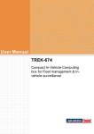
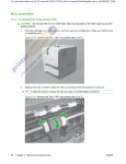
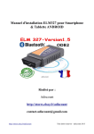
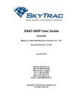
Morgan 4/4 Ford 1.8 Black Top Zetec Rev Hang Problems.
(Rev Hang) No discernable engine braking when deceleration was expected in fact
my 4/4 would continue as if I had not taken my foot completely off the accelerator.
(Flare) Driving at power given an engine speed of 2000 RPM and in the situation
above when the clutch is “dipped to change gear” the revs would flare to 3000 to 3500
revs and again hang at that level for some considerable amount of time.
(Idle speed) The 4/4 brought to rest when stopping at junctions etc, the idle speed
revs could be in excess of 1100 to 1500 revs sometimes more. (ISCV failing to
operate via pulses from the ECU.)
Having researched the control and operation of the ISCV (Idle Speed Control Valve.)
my understanding is that this device is operated from the ECU by electronic pulses to
part close the device to control the idle speed of the engine. (e.g.; no pulses ISCV
fully open, a high frequency of pulses to part close and then limit control the engine
speed with the vehicle at rest with the desired frequency pulse.)
Further research showed that on the Zetec Black Top engines there are two elements
to the TPS throttle closed position.
"The TPS reading sets the ECU in various throttle position categories; the relevant
ones here being the lowest two; "part" and "closed." When the ECU is in "part"
throttle mode the ISCV is held fully open; [capable of giving 2-3,000 revs unloaded]
when the TPS voltage drops into the tolerance zone, then it changes to "closed" and
actuates idle protocols to reduce the ISCV opening to give an enhanced idle if there is
still a pulse from the VSS [vehicle speed sensor] or a normal idle if there isn't."
The idle control on these systems is unique. It's an adaptive, learning, measurement of
the lowest TPS [throttle position sensor] voltage encountered in that drive-cycle, [the
"ratch" voltage] with the addition of a small tolerance, being compared to the current
reading from the TPS.
This is it's great weakness; if a low “ratch” voltage has been set, then the current
readings from the TPS never get low enough to be recognized as "closed" - the ECU
still remains in "part" and the ISCV stays wide open. Hence the frantic idle speed,
"idle flare" and the "cruise control" effect until long after the vehicle is stationary. The
TPS should only be able to initiate enhanced idle - the fact that it caused a lot more
would indicate that it has back-fed interference and confused the ECU [through one of
many software holes?] into going back into "part throttle" mode.
The TPS rarely fail; it's more usual that they can't get down to the centre-pin voltage
that they registered when cold; in-line joint corrosion and induced noise are only two
possibilities. As far as the TPS goes; if water had got in and was producing a fastchanging signal, that would likely be beyond the software's ability to cope. A
“flickering shash” would likely make the ECU lose its marbles.
A solution is to drill-out the TPS “screw fixing holes” and use the slack to be able to
rotate the TPS counter clock to achieve the lowest possible signal voltage. The ECU
doesn't seem to be able to accept a “ratch” voltage below 0.8v; so if you can get 0.7v
at the TPS - it can't follow it down and gets the message - throttle closed!
De-powering or resetting the ECU erases all the learned values; it needs 20 miles or
more of varied driving before it hones its settings somewhere near right and then
adjusts itself to your style over a longer period of driving.
The potentiometer type of TPS is a variable resistor, effectively supplying a gradually
increasing supply of voltage to the computer as the throttle is gradually opened. These
sensors are usually not adjustable. The two outer pins join to each end of the
carbon/resistive track and the middle pin is the arm which sweeps across this track. In
the car one end of the track is connected to 5v, the other to ground, and the wiper
output will vary from say Zero to five volts (not quite, more like 0.25-4.75v).
Although there are literally dozens of sensors that provide critical data to the engine
management computer of a modern, fuel-injected engine, few are actually adjustable,
or can be affected by adjustments of related components. The throttle position sensor,
often referred to as the TP sensor or TPS, is one of these rare devices.
It is important to get to know the function and servicing of this sensor for a couple of
reasons. As with any electro-mechanical moving part, they have been known to
malfunction or ultimately just plain wear out. Besides that, they are often victims of
improper service procedures. These procedures will either result in damage to the
sensor, or impair its range of operation. In any event, a malfunctioning damaged, or
misadjusted TPS will cause a variety of driveability symptoms, often accompanied by
a “check engine” MIL (malfunction indicator light) displayed on the instrument panel.
The TPS does just what its name implies; it provides input to the engine management
computer regarding the position of the throttle. How the computer processes that data
depends on other prevailing conditions: engine speed, load, vehicle speed, engine and
ambient temperatures, and so on. This information from the TPS is especially critical
for proper start up and idle, as well as smooth throttle response.
Early designs were often adjustable, later designs are not.
Throttle Stop and Throttle Cable Adjust.
You may already be imagining what kinds of failure and maladjustment scenarios are
possible with the different types of sensors. We'll get there momentarily, but no
discussion of proper diagnosis and adjustment of the TPS would be right without first
addressing the throttle stop, and throttle cable adjustments.
The reason that these adjustments are so important is that if they are incorrect, that is
they are holding the throttle plate open beyond specification; the TPS will not be able
to give an idle (throttle closed) signal to the computer. Driveability symptoms that
result include poor start up, engine stall after start up, poor idle, engine stall at idle,
poor throttle response at throttle "tip-in" or possibly even engine "ping." Besides those
things, you may also discover that you are unable to access the vehicle on-board
diagnostic tests, and/or unable to properly set the ignition timing!
While it may be true that adjusting the TPS may correct some of these symptoms
caused by a maladjusted throttle cable or stop, the throttle plate would still be
admitting more than its share of air at throttle close. This will cause the idle air
control valve to operate out-of-parameter, which will lead to similar, if not new and
unusual problems. If the TPS is not adjustable, the throttle cable and stop adjustments
are even more critical.
Rules of Thumb.
It's best to consult the service manual for specifics on any adjustments that we are
about to discuss, but here are a couple of rules of thumb: To make sure that the
throttle cable is only as tight as it needs to be, have a friend push the accelerator pedal
to the floor (with the engine off, please!) and then adjust the cable so that the throttle
plate just reaches the fully open position without stressing the cable.
As for the throttle stop adjustment, while it may look like an idle speed adjustment, if
it has a direct effect on throttle position, don't use it as such. Set it so that the throttle
plate is only held open enough to prevent binding of the throttle plate in the bore. At
that position, the throttle cable should have at least a little slack in it, so that the
throttle can consistently return to its stop. Do not proceed until these relationships are
correct.
Regarding TPS adjustment, most TP sensors are adjusted at throttle close. Generally
speaking, if the other adjustments are O.K., and the sensor is otherwise fully
functional, getting this adjustment correct will finish the job.
Setting potentiometer-type sensors will require the use of a voltmeter. You'll really
need the service manual for the exact voltage spec, as well as the correct wires to
connect up to. This type of sensor is usually set with the ignition on, engine off. On
ODB2 compliant ECU’s an ODB2 reader is a must use tool to enable the resetting of
the ECU adaptive learning stored information. (An ODB2 reader can be obtained for
as little as £55.00p when used with any windows USB lap top computer.)
Sometimes problems will show up during the adjustment procedure. They may point
to a malfunction in the sensor, a wiring problem, or perhaps a computer problem. If
you're feeling confident and adventurous, with the help of the service manual and a
digital volt/ohmmeter and an ODB2 reader, you might even be able to tackle those
problems too.
Adjusting your throttle position sensor.
(1) Locate the Throttle and the TPS. (Centre of the picture.)
(2) Using an ODB2 reader take a reading of the TPS at throttle closed.
(3) Disconnect the TPS flying lead.
(4) Using the following tools remove the TPS.
(5) Using a 5mm drill bit, drill out the left hand TPS “slot” biased to removing the
upper part of the slot.
(6) Using a 5mm drill bit, drill out the right hand TPS bush biased to removing
the lower part of the bush. (Allows for slight turning movement anti-clock.)
(7) Loosely refit with the screws and test the TPS throttle closed reading using the
ODB2 to be approx 0.8 volts or 16%.
(8) If required remove the TPS and using a small round file remove more of the
biased plastic refitting and testing until the desired 0.8 volts or 16% is
achieved.
(9) When the desired value has been achieved re-fit the TPS using only the tools
above and secure tight. (NB do not over tighten.) and reconnect the flying
lead.
Finally reset ECU MIL, alarms and adaptive RAM using the ODB2 reader and start
the engine and allow the engine to idle only until the “choke” cycle has been
completed and the engine is fully up to temperature. (2 cycles of the cooling fan or 15
minutes or more.) The idle speed should have set itself to approximately 750 to 800
rpm. Switch off the engine and remove the ODB2. Fundamental calibration of the
ECU will now take place over the next 20 miles of very “easy and careful” driving.
Next step is to find a long fast road where the throttle can be opened up to the max
power for some distance. (Top speed is not the objective.) To be followed by many
miles of more Morgan style driving your ECU should achieve full calibration.
Notes from the author.
This procedure is for 1.8 Zetec Black Tops only.
1.8 Zetec Silver Tops may vary.
Elmscan5 OBD2 used to measure TPS reading in % format. Other ODB2 readers
may vary by design.
Austrian/German ISCV restrictor plate fitted has not been removed. (procedure works
well with or without the plate insitu.)
This procedure may only be used at your own risk.
TPS Ford Part No 1071403.
Ford Engineering ref 988F-9B989-BB (etched on front of TPS)
BH11248 Version 2. Date 19/09/2010.