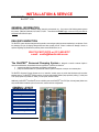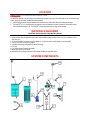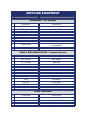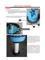
1
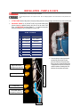
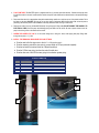
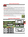
BioSTEP® Screened Pumping System Installation & Service Manual FOR USE WITH BioSTEP® 1618 BioSTEP Manual © Bio-Microbics, Inc. Revised June 2013. BioSTEP is a registered trademark owned by Bio-Microbics, Inc. INSTALLATION & SERVICE FOR USE WITH BioSTEP® 1618 GENERAL INFORMATION All BioSTEP® products are ETL certified for safety (electrical, environmental, etc.). One or more of the following patents protects this process: 3,966,599; 3,966,608; 3,972,965; 5,156,742. These directions DO NOT apply to the use of any parts that are substituted for Bio-Microbics parts. DELIVERY INSPECTION The BioSTEP® system has been designed and inspected to meet stringent quality assurance standards prior to shipment. Check the packaging for signs of shipping damage before and after uncrating the unit. If there is evidence of damage or abuse, or questions regarding any Bio-Microbics products, please contact Bio-Microbics, Inc. at: 800-753-FAST (3278) or (913) 422-0707 e-mail: [email protected] The BioSTEP® Screened Pumping System is designed to transfer screened liquids in numerous small-diameter, decentralized collection applications. It performs two functions: screens large solids from wastewater (processed or unprocessed) pumps the screened waste into a pressurized collection system for disposal or transport to a treatment plant. The BioSTEP® Screened Pumping System acts as a “sewer-like” transfer system to provide land developers with innovative treatment options. The BioSTEP® package consists of a robust solids-handling effluent pump capable of passing ¾” solids (most STEP pump systems only handle 1/8” solids), a control panel, and level controls. Additionally, the BioSTEP® ScumGuard® acts as a shield to protect each BioSTEP® from FOG (fats, oils and grease)-laden scum and provides flexible installation options for most tank, manhole and riser configurations. A. Control Panel B. Discharge Line C. ScumGuard® D. Screen E. Pump F. Screen Cleaning Swab G. Support Leg LOCATION Always have all utility lines and equipment marked by a locating service prior to performing any work. Failure to do so could result in severe bodily injury or death. The BioSTEP® system(s) may be located in the same position relative to the house and water supply as any conventional septic system. However, some basic guidelines should be followed: Avoid locating the tank in high groundwater areas where the tank could possibly float up and become dislodged. The BioSTEP® unit should be placed in the manhole as close as possible to the tank’s outlet end. This manhole should have a minimum diameter of 18”. The BioSTEP® unit should be placed in the center of this manhole. MATERIALS REQUIRED CONTRACTOR SUPPLIED FOR INSTALLATION Materials/tools required for installation: (Note: other tools may be needed to complete installation) 1. Septic tank that meets all applicable requirements and standards including manhole access >18” [46 cm] diameter for the BioSTEP® unit. 2. ¾” [19 mm] schd 80 PVC pipe is required if manhole is >22” [56 cm] and/or if swab handles are to be extended. 3. 4” Ø [101 mm] schd 40 pipe for leg support 4. Safe lifting mechanism (pump weighs 55-85 lbs [25-39 kg]) 5. PVC saw 6. PVC primer and glue (weather appropriate) 7. Mounting screws for control panel 8. All electrical conduit, fittings, specified wires and other supplies per applicable codes SYSTEM COMPONENTS Includes the following components: *assuming all parts are supplied by Bio-Microbics, Inc. SUPPLIED EQUIPMENT COMMON NAME PART NUMBER SCREENING – All Packages 1 2 3 ScumGuard® 180-SG1624 ® BioSTEP filter (1/8” slots) ® BioSTEP Screen Cap 180-SANSPMB1618 180-CAPSANSTM16 BioSTEP® Cleaning Swab 4 Wiper Blade 180-SWBREXT16 5 Handles (2) 180-HAN3/4 6 ¾” Pipe (2) 090-PIPE34SCH80 7 Retainer Parts (2) 180-STCP3/4 (2) 180-SBCP3/4 8 Foot (4” pipe not included) Top 010-FT Bottom 010-FB PUMP & DISCHARGE PIPING – Complete System 9 Pump dependant on model 10 MPT x Slip ftg 062-FTGMIP1 2” L x 2” Ø Pipe 090-PIPE2 Check Valve 059-VLV CHK 4”L x 2” Ø Pipe 090-PIPE2 Street Elbow 065-ELPCS40 Elbow 065-ELP2 33.5” L x 2”Ø 090-PIPE2 Union 059-UNION Ball Valve 059-VLVBALL 2” Ø Flex Hose 090-PIPEFLX2 Lifting Cable 096-CABLESS18 11 12 LEVEL CONTROLS 13 Control Panel 035-CPS2201 14 Junction Box 090-BOXJ Cord Grips (4) 096-GRIPSCORD Floats (4) 040-FLSWT 15 INSTALLATION - SCREENING Hazards exist in confined spaces such as a septic tank. All confined space precautions must be followed if entering a tank. Always keep tank openings covered during storage and installation 1. Place ScumGuard® (black) in center of manhole. a. If manhole is larger than 22” diam then ¾” diam Schd 80 PVC pipe should be used to hang the ScumGuard® in the manhole by drilling a hole in the ScumGuard® in the designated location and running the pipe through the hole. 2. Place the screen (w/ exterior swab) inside the ScumGuard®. The screen MUST rest as far down in the ScumGuard® as possible. 2 MIN N) 1 1a 3 ¾” [9.5 cm] clearance 3. SUPPORT LEG The support leg (if needed) is meant to support the pump. Cut a piece of 4”Ø [101 mm] schd 40 PVC pipe to the desired length (be sure length is correct). Glue the pipe to the two leg ends. Attach the leg to the bottom of the BioSTEP® screen using stainless steel screws. 4. EXTENDING SWAB HANDLES –The exterior cleaning swab pipes may be easily extended using ¾” schd 80 pipe and matching couplings. Cut ¾“ pipes to the desired length, glue and connect each extension pipe to the existing pipes using slip-to-slip couplings. When completed, glue the supplied swab handle to each pipe end. INSTALLATION - PUMP & FLOATS Hazards exist in confined spaces such as a septic tank. All confined space precautions must be followed if entering a tank. Always keep tank openings covered during storage and installation Use safe lifting techniques to set components in tank. Be sure all lifting equipment is clear of obstructions such as power lines and trees. 1. LIFTING CABLE Attach a lifting cable to the pump making sure that it is long enough to extend to the top of the manhole riser. 2. DISCHARGE PIPING Dry fit (DO NOT GLUE) the provided outlet piping (pieces should be numbered) starting with piece #1 at the outlet of the pump. It is IMPORTANT to arrange pieces # 1 – 7 so that the piping exits the screen through the hole in the BioSTEP® screen’s cap. STEP 2 PARTS NAME PART NUMBER 1 MPT x slip ftg 062-FTGMIP1 2 2”L x 2”Ø pipe 090-PIPE2 3 Check valve 059-VLV CHK 4 4”L x 2” Ø Pipe 090-PIPE2 5 Street Elbow 065-ELPCS40 6 Elbow 065-ELP2 7 33.5” L x 2”Ø 090-PIPE2 Clamps w/ snubbers at desired levels High water alarm/ emergency pump ON Pump ON Pump OFF Low water alarm/ emergency pump OFF Pump 3. Once the piping is properly positioned, permanently glue the parts in place (piece #1 screws into the pump outlet). Be sure to use a primer and solvent that is appropriate for schd 40 PVC and your weather conditions. Carefully follow all directions for the primer and solvent. 4. FLOAT SWITCHES The BioSTEP system is supplied with four (4) normally open float switches. Determine the proper level for each float switch in the tank. Install each float switch clamp with cord snubber at the desired levels on the pump discharge piping. 5. Place each float switch in its appropriate clamp with snubber being careful not to strip the nut out of the plastic snubber. Place the floats so that they CAN NOT get hung up on any other piece of equipment. Mark the float wire ends so that the person performing the electrical portion of the installation can easily determine which wires go to which float. 6. Remove the screen’s top cap (left hand/CCW thread). Using the pump’s lifting cable (DO NOT HANDLE THE PUMP BY ITS ELECTRICAL CORD) lower the pump with discharge piping and floats into the screen. Be sure to place at least one of the pump’s feet in the groove on the bottom of the screen. 7. SCREW THE SCREEN TOP CAP on to the screen being sure to bring ALL wires, outlet piping and pump lifting cable through the top cap’s ~2 ½” hole. 8. INSTALL THE REMAINING DISCHARGE PIPE AND FITTINGS. a. b. c. d. e. Glue the male half of the pipe union to the 33.5” L x 2”Ø pipe from step 2. Glue the remaining parts of the pipe union to a proper length of 2”Ø pie (contractor supplied). Glue the ball valve to the other end of the 2”Ø pipe from step b. Glue the 2”Ø flex hose piping into the other end of the ball valve. Glue the other end of the 2”Ø flex hose piping to the collection system piping. STEP 8 PARTS Step NAME PART NUMBER 8a & b Union 059-UNION 8c Ball Valve 059-VLVBALL 8d 2” Ø Flex Hose 090-PIPEFLX2 8d 8a 8b 8c INSTALLATION-ELECTRICAL All electrical work shall be performed by a qualified electrician per all applicable codes. Failure to do so may result in severe bodily injury or death. Always have all utility lines and equipment marked by a locating service prior to performing any work. Failure to do so could result in severe bodily injury or death. 1. BEFORE STARTING Check the electrical specifications of the supplied components. If you have ANY questions please call Bio-Microbics, Inc. at 800-735-3278 or (913)422-0707. It is the responsibility of the contractor/ electrician to use proper installation materials for compliance with all codes and prevention of any electrical problems such as interference, transients (spikes), conduit transmission of moisture and sewer gasses, etc. 2. JUNCTION BOX Bio-Microbics recommends mounting the junction box outside of the BioSTEP® tank and access riser. The pump and each float switch will have a set of wires coming from the BioSTEP® into the junction box(es). The float switch wires and pump wires MUST be run in separate conduits and junction boxes UNLESS each float switch uses class SJOOW insulation or better. Use the supplied cord grips (or other fittings as appropriate) to bring each set of wires into the junction box(es). The supplied cord grips require a ¾”Ø hole in the junction box. Use appropriate exit fitting(s) and conduit(s) for running the wires to the control panel. The junction box’s water tight integrity must be maintainted. 3. Mount the control panel at a suitable location. Some factors when considering location are: accessibility for different peoples (or not), flooding/wetness potential, code requirements, access for system repair, voltage drop, to name a few. Run all wires to and from the panel using the appropriate fitting(s) and conduit(s). Incoming and pump power wires may be run in the same conduit (provided code requirements are met). Make all wire connections inside the panel using the picture below as a guide. Always maintain the watertight integrity of the control panel. 4. DO NOT TURN POWER ON YET (this will cause the pump to run dry). To turn the pump ON and OFF manually use the HOA switch inside the control panel (see picture on right). ELECTRICAL WIRING DIAGRAM BioSTEP® Control Panel Detail: FOR 110V POWER: Power IN L N HWA ON OFF LWA L1 L2 Low Water OFF ON L1 L2 High Water External input Signal Dialer contacts “Optional” L N N FLOATS EXT To PUMP N T1 T2 G POWER IN L1 L2 G To PUMP FOR 220V POWER: FINAL INSPECTION & START UP It is the responsibility of the installer to ensure that the tank will not float due to hydraulic conditions at the site. Your local BioMicrobics distributor may provide installation inspection services. If you have questions, call Bio-Microbics at 800-753-FAST (3278) or (913) 422-0707. Persons coming in contact with wastewater, must immediately wash all exposed areas with disinfecting cleaner and contact your personal physician. Failure to do so could result in severe sickness or death. 5. Fill the tank with water to prevent floatation so that the BioSTEP® system can be safely tested. DO NOT test run the pump if it is not fully submerged. To turn the pump ON and OFF manually use the HOA switch inside the control panel (see picture on right). 6. Check the alarm and pump for proper function. The system automatically goes into ON mode (pump obeys the floats) five (5) seconds after power is supplied to the control panel. Set the floats to test for each of the following conditions: Normal pump ON, normal pump OFF, lower water alarm & emergency pump OFF, high water alarm & emergency pump ON. If the alarm does not sound within 15 seconds after the alarm floats are activated, then review the electrical installation procedures. 7. Backfill the excavation. 8. Lastly, record the BioSTEP® unit’s serial number on the back page of this manual. OPERATION & MAINTENANCE The BioSTEP® System should be checked and maintained for optimal performance. BioSTEP® SCREEN The screen should be cleaned periodically according to conditions at each point of use. To clean the screen, simply move the screen’s swab up and down vigorously at least 6 times. Be sure to move the two handles evenly. ALARM PANEL Check the alarm and pump for proper function. FLOATS Set the floats to test for each of the following conditions: Normal pump ON, normal pump OFF, lower water alarm & emergency pump OFF, high water alarm & emergency pump ON. If the alarm does not sound within 15 seconds after the alarm floats are activated, then review the electrical installation procedures. PUMP If you need to turn the pump On or OFF manually, use the HOA switch in the panel (see picture above). If you are using a Bio-Microbics supplied Goulds pump, then you should reference the Goulds manual concerning pump operation and maintenance. If you are not using a Bio-Microbics supplied pump then reference the manual supplied with the pump being used. PARTS Replacement and spare parts can be obtained from your local Bio-Microbics distributor. For assistance in locating a distributor near you call Bio-Microbics at 800-753-3278 or (913) 422-0707. LIMITED 12-Month WARRANTY Bio-Microbics, Inc. warrants every new BioSTEP® system against defects in materials and workmanship for a period of one year after installation or eighteen months from date of shipment, whichever occurs first, subject to the following terms and conditions: During the warranty period, if any part is defective or fails to perform as specified when operating at design conditions, and if the equipment has been installed and is being operated and maintained in accordance with the written instructions provided by BioMicrobics, Inc., Bio-Microbics, Inc. will repair or replace at its discretion such defective parts free of charge. Defective parts must be returned by owner to Bio-Microbics, Inc.’s factory postage paid, if so requested. The cost of labor and all other expenses resulting from replacement of the defective parts and from installation of parts furnished under this warranty and regular maintenance items such as filters or bulbs shall be borne by the owner. This warranty does not cover general system misuse or any components that have been disassembled by unauthorized persons, improperly installed or damaged due to altered or improper wiring or overload protection. This warranty applies only to the pumping system and does not include any of the house wiring, plumbing, drainage, septic tank or disposal system. Bio-Microbics, Inc. reserves the right to revise, change or modify the construction and/or design of the BioSTEP system, or any component part or parts thereof, without incurring any obligation to make such changes or modifications in present equipment. Bio-Microbics, Inc. is not responsible for consequential or incidental damages of any nature resulting from such things as, but not limited to, defect in design, material, or workmanship, or delays in delivery, replacements or repairs. THIS WARRANTY IS IN LIEU OF ALL OTHER WARRANTIES EXPRESS OR IMPLIED. BIO-MICROBICS SPECIFICALLY DISCLAIMS ANY IMPLIED WARRANTY OF MERCHANTABILITY OR FITNESS FOR A PARTICULAR PURPOSE. NO REPRESENTATIVE OR PERSON IS AUTHORIZED TO GIVE ANY OTHER WARRANTY OR TO ASSUME FOR BIOMICROBICS, INC., ANY OTHER LIABILITY IN CONNECTION WITH THE SALE OF ITS PRODUCTS. Contact your local distributor for parts and service. BioSTEP Device