1
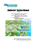
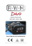
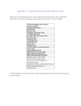
BioBarrier® Installation Manual
FOR USE WITH
NSF/ANSI Std. 40 Class I / 245 / 350 Class R
BioBarrier® 0.5, 1.0, and 1.5
NSF/ANSI Std. 40 Class I / 245 / 350 Class R
BioBarrier® 0.5-N, 1.0-N, and 1.5-N
non- ANSI/NSF certified
BioBarrier® 2.0, 2.5 3.0
BioBarrier® HSMBR® 1.5, 3.0, 4.5, 9.0
BioBarrier Installation Manual © 2015 Bio-Microbics, Inc. Revised April 2015.
BioBarrier and HSMBR are registered trademarks owned by Bio-Microbics, Inc.
Other trademarks used are registered by their respective owners.
INSTALLATION MANUAL
FOR USE WITH
NSF/ANSI Std. 40 Class I / Std. 245 / STD. 350 Class R
BioBarrier® 0.5, 1.0, and 1.5
BioBarrier® 0.5-N, 1.0-N, and 1.5-N
non-NSF certified BioBarrier® HSMBR® 1.5, 3.0, 4.5 and 9.0
GENERAL INFORMATION
The BioBarrier® 0.5, 0.5-N, 1.0, 1.0-N, 1.5 & 1.5-N membrane bioreactor wastewater treatment systems are certified by the NSF
International/ American National Standards Institute Organizations to meet NSF/ANSI Standard 40, Class 1 certification for
single residence wastewater treatment devices, NSF/ANSI Standard 245 for nitrogen reduction, and NSF/ANSI Standard 350
Class R for restricted indoor and unrestricted outdoor use, such as toilet, urinal flushing and surface and subsurface irrigation. All
BioBarrier® products are ETL certified for safety (electrical, environmental, etc.). If you have questions regarding any BioMicrobics products please contact us at:
800-753-FAST (3278) or (913) 422-0707
e-mail: [email protected]
DELIVERY INSPECTION
The BioBarrier® system has been carefully manufactured, checked and tested at the factory before shipment. Before and after
uncrating the unit, check the packaging for signs of shipping damage. If there is evidence of damage or abuse, notify BioMicrobics, Inc. at (800) 753-3278 or (913)422-0707.
THE BIOBARRIER® SYSTEM
The BioBarrier® System, is a membrane bioreactor providing primary settling, fecal coliform, BOD, TSS and nitrogen reduction
(if needed) using aeration and anoxic zones, and membrane filtration. The system is contained in locally supplied tanks, either in
a two or three compartment tank, or multiple tanks, with the membrane module always in the last compartment/ tank of the
system. The membrane module itself consists of flat sheet membranes arranged in a cartridge. A high mixed liquor suspended
solids concentration in the aeration zone provides biological treatment and nitrification. The final effluent or permeate is pulled
out by the permeate pump through the MBR membranes leaving behind large organic and inorganic particles for further digestion
or wasting.
If nitrogen removal is not needed the system (BioBarrier® 0.5, 1.0, and 1.5) consists of a tank with two compartments or two
separate tanks. The first compartment or tank provides primary treatment - sedimentation and separation of floatables and
solids, and is equipped with an outlet screening device called SaniTEE®. From this screened compartment or tank, the
wastewater will flow into the second compartment or tank, which is the aeration/membrane zone.
A. Tank
B. SaniTEE®
C. Blower & Housing
D. Control Panel
E. Vent
F. Float Tree
G. BioBarrier Reactor
H. Optional Mixing
Pump
If nitrogen removal is needed the system (The BioBarrier® 0.5-N, 1.0-N, 1.5-N) consists of a tank with three compartments, or
two tanks totaling at least three compartments, with exactly two compartments in the second or final tank. The first compartment
or tank provides primary treatment - sedimentation and separation of floatables and solids, and is equipped with an outlet
screening device called SaniTEE®. The second and third compartments must be in the same tank, and the second compartment
is where denitrification takes place under anoxic conditions. The third compartment, the aeration/membrane zone, is separated
from the anoxic zone by a baffle wall between the two zones to allow nitrified waste to enter into the anoxic area for
denitrification.
NSF Standard 350 Class R Restricted Indoor Urban Reuse Water
The BioBarrier® system has been tested under NSF Standard 350 Class R (Residential) and is capable of treating residential
wastewater for restricted indoor urban water reuse, which is toilet and urinal flushing. The system design requires a holding tank
and plumbing system for reuse water and shall meet all applicable codes; have proper backflow prevention and protection
against cross connections; and is the responsibility of the local designer/installer. When the reuse water is used for toilet and
urinal flushing, additional disinfection should be considered to provide adequate assurance in preventing microorganism growth
in the treated reuse water storage tank and as required by applicable codes.
The reuse tank shall be located after the BioBarrier® system. This tank shall also incorporate an overflow that allows excess
reuse water to be dispersed in a locally approved soil dispersal system or released into a sanitary sewer system. A potable
water make up system shall also be available to supply water when treated reuse water is not available. This potable water make
up system shall include a properly designed backflow preventer that meets all applicable codes.
NSF Standard 350 Class R Unrestricted Outdoor Urban Reuse Water
The BioBarrier® system has been tested under NSF Standard 350 Class R (Residential) and is capable of treating residential
wastewater for unrestricted outdoor urban water reuse, which is acceptable for use in surface and subsurface irrigation, including
irrigation of edible crops without the edible portion being in direct contact with the treated water. A reuse tank may be required if
the irrigation system requires it. The holding tank and plumbing system for reuse water shall meet all applicable codes; have
proper backflow prevention and protection against cross connections; and is the responsibility of the local designer/installer.
Additional disinfection should be considered to provide adequate disinfection to prevent microorganism growth in the treated
reuse water storage tank and as required by applicable codes.
If a reuse tank is required for irrigation, it shall be located after the BioBarrier® system. This tank shall also incorporate an
overflow that allows excess reuse water to be dispersed in a locally approved soil dispersal system or released into a sanitary
sewer system. If a potable water make up system is required for irrigation, it shall include a properly designed backflow preventer
that meets all applicable codes.
INSTALLATION PROCEDURE
Always have all utility lines and equipment marked by a locating service prior to performing any work. Failure to do so
could result in severe bodily injury or death.
Hazards exist in confined spaces such as a septic tank. All confined space precautions must be followed if entering a
tank. Always keep tank openings covered during storage and installation
MATERIALS REQUIRED FOR INSTALLATION
A. Septic tank that meets all applicable requirements and standards.
B. Recognized, safe lifting mechanism for treatment module (e.g. a tripod).
C. Non-corrosive strut channel or equivalent material that is able to hold down at least 550 pounds [250 kg] of
buoyant force (see step 29).
D. Stainless steel anchor bolts to secure strut channel to tank riser and blower housing to concrete base.
E. Piping for all air and vent lines. Check the install procedure all specs, and plans to determine what sizes
and types of pipe you may need.
F. PVC saw
G. Pipe joint lubricant/soap.
H. PVC primer and glue.
I. Concrete base for blower assembly.
J. Mounting screws for control panel.
K. Electrical conduit, fittings and wire for required wiring.
L. Hammer Drill and concrete bits.
SaniTEE® Installation Screen
1. Check the specifications of the BioBarrier unit to determine the required number
of SaniTEE screens to be installed.
2. A 4” SaniTEE® fits in the 4” septic tank outlet tee or sweep (Schd 35, 40 & 80)
JUST PRIOR to the BioBarrier system. The center of the SaniTEE® outlet
MUST be at least 38 inches [96.5 cm] off the bottom of the tank.
3. Place the SaniTEE® into the outlet tee. DO NOT USE GLUE. The SaniTEE
should fit snugly into the outlet tee.
4. OPTIONAL - EXTENDING SWAB HANDLES – The exterior cleaning swab
pipes may be easily extended using ¾” schd 80 pipe and matching couplings.
Cut ¾” pipes to the desired length, glue and connect each extension pipe to the
existing pipes using slip-to-slip couplings. When completed, glue the supplied
swab handle to each pipe end.
5. Reattach the SaniTEE® handle with solvent welding to the ¾” Schd 80 swab
shaft or added extension pipe.
BioBarrier MODULE INSTALLATION
Use safe lifting techniques to set module in tank. Be sure all lifting equipment is clear of obstructions such as power
lines and trees.
1.
The BioBarrier system should be placed as far toward the outlet end of the treatment tank as possible.
2. Before installation may begin, check the tank to ensure it is level within ¼” [6 mm] from inlet to outlet and ¼”
[6 mm] from side to side to side.
3. Install the SaniTEE® wastewater screen in the outlet tee of the settling tank/compartment (see SaniTEE®
Installation instructions).
4. If a pump tank is used after the BioBarrier system,
then this tank must be placed as close to the
BioBarrier tank as possible.
5. If the tank is smaller than the minimum dimensional
range specified, the BioBarrier® system may not
operate properly. The effluent quality could suffer
and may not meet site requirements.
INITIAL CONNECTIONS Steps 6 -10 are best performed prior to placing the module in
the tank.
6. Screw the provided 2” Ø PVC MPT x slip fitting into the air line grid.
7.
Measure the depth of the tank from the bottom to the top of the tank manhole. Cut one section of 2” Ø PVC
schedule 40 pipe [51 mm] for the air line and two sections of schedule 80 ¾” [19 mm], for bracing the
system, to this length.
8. Solvent weld the 2” air line to the
BioBarrier’s air line connection.
9. Use the supplied stainless steel bolts and
nuts to secure the ¾” pipes to the top of the
BioBarrier housing at the provided recesses.
10. Make the initial discharge line connections
by attaching a piece of 5/16” [8 mm] tubing to the
water discharge port of the BioBarrier’s pump. Make
sure this length of tubing is long enough to reach the
tank exit once the unit is placed in the tank.
11. For BioBarrier 0.5, 1.0, 1.5 ONLY - Attach
the ¾” schedule 40 (or schd 80) pipe for the
discharge pump vent to the supplied discharge
assembly. Make sure the piping is long enough to
reach into the air space in the tank’s manhole. Water
MUST NEVER enter this vent pipe (see step 15 pic).
12. Using the supplied lifting cables, lower the
BioBarrier unit into the treatment tank and postion the
unit so that it is directly under the manhole.
AIR LINE
13. In the manhole, make connections so that the BioBarrier air line exits the tank for connection to the blower.
The air line must be firmly secured to the tank to prevent vibrational breakage.
14. From the blower, run 2” [51 mm] schedule 40 PVC piping to the connection point at the treatment tank.
Make sure pipe union is installed as shown and that all connections are permanent. This line may not
exceed 40 ft [12 m] in total length. DO NOT use any more than four elbows in this line.
15. At the blower, use the supplied fittings to connect the inlet filter assembly and initial outlet piping.
DISCHARGE PUMP
16. Residential BioBarrier® - The Discharge Pump, pump vent line, and discharge
tubing MUST be assembled at the job to prevent shipping damage.
17.
Pump fittings:
a. Screw PVC Tee on to pump intake. DO NOT glue Tee to pump intake.
b. Solvent weld short piece of ¾” Ø PVC pipe into Tee (see picture).
c. Connect and clamp 1” ID x 3.5” L flex tubing to PVC pipe from previous
step (16b). Firmly tighten the clamp to between 2 – 10 ft-lbs of torque. DO
NOT crack the PVC pipe.
d. Connect and clamp ½” ID x 10’ L flex tubing to the
threaded pump discharge. Firmly tighten the clamp to
between 2 – 10 ft-lbs of torque. DO NOT crack the pastic
pump nipple.
e. Connect and clamp 1” ID x 3.5” L flex tubing and entire
pump assembly to BioBarrier outlet nipple.
18. Make connections in the treatment tank manhole for the 5/16” [8 mm] discharge line (from step 9) to exit the
tank. This exit point MUST NOT be any higher than five feet above the pump. It is preferred that this exit
point be placed in the manhole access.
19. Outside of the treatment tank the discharge may be increased in size. Make connections from the treatment
tank exit to the final discharge tank/method. The discharge line MUST NOT increase in elevation in
reference to its exit point from the treatment tank.
20. Install a vent line on the Discharge Pump by solvent welding ¾” Ø PVC pipe to the opposite side of the PVC
Tee (see #20 in above picture). Vent line must terminate in the access riser for easy use. See step 22.
21. BioBarrier HSMBR® discharge pump MUST be installed in an area that will not allow moisture to get to the
motor.
a. Firmly secure the pump so that its torque does not damage the piping.
b. We recommend the use of a vacuum gauge and one way valve on the pump intake. The pump has a
built-in screw for priming the pump, however a ball valve on the outlet may be preferred. All of these
recommended parts can make service easier.
c. Connect the discharge piping from the membrane treatment system to the discharge pumps.
VENTING
22. The ¾” [19 mm] vent/Clean In Place (CIP) line for the discharge pump (connected in step 20) should be
terminated with a ball valve in the manhole in a location that is easy to reach. Make sure the ball valve is in
the CLOSED position until the tank is to be filled with water (see FINAL INSPECTION & STARTUP).
23. A treatment tank aeration vent must be installed in the manhole riser. This vent must be at least 4” diameter
[101 mm] and must drain all moisture that will build up in the vent. The vent opening must contain at least
7.1 in2 [45.8 cm2] open surface area and be properly secured to prevent unauthorized access. The vent line
MUST NOT allow excess moisture nor back pressure to build up.
If you have any questions
please call Bio-Microbics at
800-753-3278 or 913-422-0707
CONTROL PANEL & FLOATS
All electrical work shall be properly performed by a qualified electrician per all applicable codes. Always
have all utility lines and equipment marked by a locating service prior to performing any work. Failure to
do so may result in severe bodily injury or death.
The BioBarrier control panel, and all electrical parts supplied with the BioBarrier® system are ETL (UL equivalent) certified for
electrical safety. The control panel meets NEMA4X standards for all weather use (not explosive or submerged environments).
24. Install the floats on a pipe within 24” [61] of a BioBarrier membrane
module. DO NOT attach the floats to the aeration piping. Attach the
BLUE and YELLOW floats to the float tree at the locations shown. The
BLUE float switch uses ONLY the brown and black wires. The
YELLOW FLOAT switch MUST be installed no higher than 2 inches [5
cm] BELOW the tank’s inlet.
25. In the treatment tank, make connections to facilitate exiting of the
wiring from the discharge pump and the float switches. If a junction box
is used inside the treatment tank manhole, waterproof connectors must
be used.
26. Run these wires to the control panel. The float wires MUST be run
in separate conduit from any power wires.
27. Mount the BioBarrier control panel in a location that is accesible to
a service person, meets all code requirements and prevents voltage
drop. The 110VAC panel requires a 15A breaker minimum. The
220VAC control requires a 20A breaker minimum.
28. Make connections inside the control panel as shown in the
diagrams included with the panel (and at the end of this manual). Note
that ONLY the BROWN and BLACK wires on the BLUE float are to be
connected to the control panel.
SECURING THE SYSTEM
29. Mount the 3 supplied channel strut pieces and associated hardware in the manhole so that the ¾” bracing pipes (from
steps 7 & 9) can be secured to the strut channel. Mount the strut end pieces to the tank riser using the supplied
stainless steel anchor bolts or other corrosion proof hardware.
30. Use “C” shaped brackets to fasten the ¾” bracing pipes to the strut channel so that the the BioBarrier system is held in
place in the tank.
31. Backfill the tank per professional judgment/requirements.
BLOWER INSTALLATION
Always have all utility lines and equipment marked by a locating service prior to performing any work. All electrical work
shall be properly performed by a qualified electrician per all applicable codes. Failure to do so could result in severe
bodily injury or death.
The blower housing should be placed on a concrete slab. Both the electrical conduit and air supply line should pass through the
concrete slab from below grade. The electrical supply conduit should be run from the control panel to the desired blower location.
A precast concrete slab can be used by drilling the appropriate holes for the air supply line.
CONNECT BLOWER PIPING
a. Longest pipe
b. Elbow
c. Air filter assembly
d. Shortest pipe
e. Reducer bushing
a
c
d
b
32
33
USE TEFLON SEALANT TAPE
ON ALL PIPE CONNECTIONS.
e
32. Secure blower assembly to base using four (4) 14# x 1½” self-tapping screws (supplied w/ unit). Drill
screws directly into blower base.
33. Connect air line (supplied by contractor) from blower outlet to BioBarrier® unit from step 2 (MODULE
INSTALLATION) using required piping (check unit specs). Blower piping to BioBarrier® may not exceed 40
ft (12 m) total length and use a maximum of 4 elbows. ALL CONNECTIONS MUST BE AIR-TIGHT AND
PERMANENT. We recommend the use of a union for easy disconnection of the blower piping. Keep all
debris out of air line.
34. Wire the blower to accept the proper voltage for your specific location according to the diagrams of each
blower.
FINAL INSPECTION & START UP
It is the responsibility of the installer to ensure that the tank will not float due to hydraulic conditions at the
site. Your local BIOBARRIER® Systems distributor may provide installation inspection services. If you have
questions, call Bio-Microbics at 1-800-753-3278 ((913)422-0707).
Persons coming in contact with wastewater, must immediately wash all exposed areas with disinfecting cleaner and
contact your personal physician. Failure to do so could result in severe sickness or death.
BEFORE THE UNIT IS BACKFILLED:
A. Open the vent/CIP ball valve from STEP 22 so that air can escape while filling the tank with water. This
valve MUST be closed prior to turning the system ON
B. Fill the tank to the normal operating level. AT LEAST 2 GALS OF ACTIVATED SLUDGE MUST BE PUT
INTO THE BIO BARRIER TANK.
C. Fill the tank to the normal operating level.
D. Check for leaks in all water-tight seals.
E. CLOSE THE VENT/CIP BALL VALVE.
F. Turn on power to the control panel. The green light will flash for ~5 seconds and then the blower will start.
Once the blower has started a robust boiling action should be present in the tank. The system is now in
automatic run mode.
G. Determine if excessive back pressure is present: Replace all access covers, place hand about 8 inches [20
cm] from BioBarrier® vent, if air flow is felt then excessive back pressure exists and the system’s vent must
be upgraded.
H. Check for proper alarm function. Press the ENTER/MANUAL switch. The alarm should sound. Once this
has taken place press the ENTER/MANUAL switch again to return the system to automatic running mode.
Use the YELLOW FLOAT switch to activate the high water alarm of the system.
I. Backfill the excavation.
J. Lastly, record the BioBarrier® unit’s serial number in the Service Manual.
NSF® INTERNATIONAL
CERTIFIED SYSTEMS SERVICE POLICY
All NSF (National Sanitation Foundation)/ANSI Standard 40 Class I / Standard 245 / Standard 350 Class R certified
wastewater treatment systems (BioBarrier® 0.5, 0.5-N, 1.0, 1.0-N, 1.5, and 1.5-N) have an initial two-year service agreement
included with the system’s initial purchase price (two service calls per year). The NSF service calls ONLY cover NSF certified
systems; other components of the septic system are NOT covered.
If there are any deficiencies in the BioBarrier® system’s operation or components, the service person will notify the owner in
writing and detail when these deficiencies can be fixed.
The company listed on the blower housing or control panel label performs this service. During an NSF service call, the
service company shall inspect the blower for proper operation, visually inspect the system’s effluent for clarity, clean the
blower air filter and assure proper function of the control panel. If these service calls are not performed on your NSF certified
system, or not all of the items are checked, please call Bio-Microbics at:
800-753-FAST(3278) or (913)422-0707
For continual service of NSF certified systems beyond the first two years, an extended service agreement is available through
your local Distributor or current service provider. This policy should provide the same services and may include any
additional services that are required by local regulation.
WIRING DIAGRAMS
SMALL CONTROL PANEL
FOR BioBarrier® (0.5-1.5) UNITS ONLY (not HSMBR® units)
BLOWER FOR BioBarrier 0.5
LIMITED WARRANTY
Bio-Microbics, Inc. warrants every new residential BioBarrier® system against defects in materials and workmanship for a period of two years after installation or three years
from the date of shipment, subject to the following terms and conditions, and commercial BioBarrier HSMBR® system for a period of one year after installation or eighteen
months from date of shipment, whichever occurs first, subject to the following terms and conditions:
During the warranty period, if any part is defective or fails to perform as specified when operating at design conditions, and if the equipment has been installed and is being
operated and maintained in accordance with the written instructions provided by Bio-Microbics, Inc., Bio-Microbics, Inc. will repair or replace at its discretion such defective
parts free of charge. Defective parts must be returned by owner to Bio-Microbics, Inc.’s factory postage paid, if so requested. The cost of labor and all other expenses
resulting from replacement of the defective parts and from installation of parts furnished under this warranty and regular maintenance items such as filters or bulbs shall be
borne by the owner. This warranty does not cover general system misuse, aerator components which have been damaged by flooding or any components that have been
disassembled by unauthorized persons, improperly installed or damaged due to altered or improper wiring or overload protection. This warranty applies only to the
treatment plant and does not include any of the house wiring, plumbing, drainage, septic tank or disposal system. Bio-Microbics, Inc. reserves the right to revise, change or
modify the construction and/or design of the BioBarrier® system, or any component part or parts thereof, without incurring any obligation to make such changes or
modifications in present equipment. Bio-Microbics, Inc. is not responsible for consequential or incidental damages of any nature resulting from such things as, but not
limited to, defect in design, material, or workmanship, or delays in delivery, replacements or repairs.
THIS WARRANTY IS IN LIEU OF ALL OTHER WARRANTIES EXPRESSED OR IMPLIED. BIO-MICROBICS SPECIFICALLY DISCLAIMS
ANY IMPLIED WARRANTY OF MERCHANTABILITY OR FITNESS FOR A PARTICULAR PURPOSE.
NO REPRESENTATIVE OR PERSON IS AUTHORIZED TO GIVE ANY OTHER WARRANTY OR TO ASSUME FOR BIO-MICROBICS,
INC., ANY OTHER LIABILITY IN CONNECTION WITH THE SALE OF ITS PRODUCTS.
Contact your local distributor for parts and service.
SERVICE AFTER THE FIRST TWO YEARS
An Extended Service Policy is available and may be purchased through your local Bio-Microbics distributor. The extended service policy should provide the same service
checks as the initial NSF service policy, sludge accumulation levels in the septic and FAST tanks, and perform any additional service required by local regulation. Extended
service on NSF certified systems should be performed twice per year.
BioBarrier ID