1
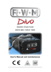
BioBarrier® Service Manual FOR USE WITH NSF/ANSI Std. 40 Class I / 245 / 350 Class R BioBarrier® 0.5, 1.0, and 1.5 NSF/ANSI Std. 40 Class I / 245 / 350 Class R BioBarrier® 0.5-N, 1.0-N, and 1.5-N non- ANSI/NSF certified BioBarrier® 2.0, 2.5, 3.0, BioBarrier® HSMBR® 1.5, 3.0, 4.5, 6.0, 9.0 BioBarrier Installation Manual © 2015 Bio-Microbics, Inc. Revised April 2015. BioBarrier and HSMBR are registered trademarks owned by Bio-Microbics, Inc. Other trademarks used are registered by their respective owners. SERVICE MANUAL FOR USE WITH NSF/ANSI Std. 40 Class I/Std. 245/Std. 350 Class R BioBarrier® 0.5, 1.0, and 1.5 non-NSF certified BioBarrier® 2.0, 2.5, 3.0 BioBarrier® HSMBR® 1.5, 3.0, 4.5, 6.0, 9.0 GENERAL INFORMATION The BioBarrier® 0.5, 1.0 and 1.5 systems are certified by the NSF International/ American National Standards Institute Organizations to meet NSF/ANSI Standard 40, Class 1 certification for single residence wastewater treatment devices, NSF/ANSI Standard 245 for nitrogen reduction, and NSF/ANSI Standard 350 Class R for Residential water reuse applications. All BioBarrier® products are ETL certified for safety (electrical, environmental, etc.). If you have questions regarding any Bio-Microbics products please contact us at: 800-753-FAST (3278) or (913) 422-0707 e-mail: [email protected] DELIVERY INSPECTION The BioBarrier® system has been carefully manufactured, checked and tested at the factory before shipment. Before and after uncrating the unit, check the packaging for signs of shipping damage. If there is evidence of damage or abuse, notify Bio-Microbics, Inc. at (800) 753-3278 or (913)422-0707. THE BIOBARRIER® SYSTEM The BioBarrier® Membrane Bioreactor combines the activated sludge treatment process with the exceptional clarification properties of a membrane. The system utilizes a three compartment tank (or separate tanks). Primary treatment consists of sedimentation and separation of floatables and solids, and occurs in the first compartment. The second compartment can be used to enhance the BioBarrier’s nitrogen reducing capabilities. The third compartment houses the BioBarrier system. The BioBarrier’s blower aerates the wastewater for naturally occurring bacteria (biomass) to grow and treat the sewage. The membrane prevents most particles from being discharged into the receiving environment. The clean water is discharged to the receiving environment by the effluent pump. The aerator also helps limit the rate of fouling on the membrane sheets. This is a continuous process provided the biomass is supplied with waste (food) and air in a suitable environment. Bio-solids (sludge) settle in the bottom of the septic tank for periodic pump-out removal. A vent pipe allows for venting of non-harmful by-products created by the process. The entire process produces effluent with very low levels of coliform bacteria, organic matter (BOD), solids (TSS) and Total Kjeldal Nitrogen. Only qualified service persons should open any access port or cover on the system. Hazards such as electric shock and Infectious organisms exist in these areas. Persons coming in contact with wastewater, must immediately wash and disinfect all exposed areas and contact your personal physician. Failure to do so could result in severe sickness or death. If nitrogen removal is needed the system (The BioBarrier® 0.5-N, 1.0-N, 1.5-N) consists of a tank with three compartments, or two tanks totaling at least three compartments, with exactly two compartments in the second or final tank. The first compartment or tank provides primary treatment - sedimentation and separation of floatables and solids, and is equipped with an outlet screening device called SaniTEE®. The second and third compartments must be in the same tank, and the second compartment is where denitrification takes place under anoxic conditions. The third compartment, the aeration/membrane zone, is separated from the anoxic zone by a baffle wall between the two zones to allow nitrified waste to enter into the anoxic area for denitrification. NSF Standard 350 Class R Restricted Indoor Urban Reuse Water The BioBarrier® system has been tested under NSF Standard 350 Class R (Residential) and is capable of treating residential wastewater for restricted indoor urban water reuse, which is toilet and urinal flushing. The system design requires a holding tank and plumbing system for reuse water and shall meet all applicable codes; have proper backflow prevention and protection against cross connections; and is the responsibility of the local designer/installer. When the reuse water is used for toilet and urinal flushing, additional disinfection should be considered to provide adequate assurance in preventing microorganism growth in the treated reuse water storage tank and as required by applicable codes. The reuse tank shall be located after the BioBarrier® system. This tank shall also incorporate an overflow that allows excess reuse water to be dispersed in a locally approved soil dispersal system or released into a sanitary sewer system. A potable water make up system shall also be available to supply water when treated reuse water is not available. This potable water make up system shall include a properly designed backflow preventer that meets all applicable codes. NSF Standard 350 Class R Unrestricted Outdoor Urban Reuse Water The BioBarrier® system has been tested under NSF Standard 350 Class R (Residential) and is capable of treating residential wastewater for unrestricted outdoor urban water reuse, which is acceptable for use in surface and subsurface irrigation, including irrigation of edible crops without the edible portion being in direct contact with the treated water. A reuse tank may be required if the irrigation system requires it. The holding tank and plumbing system for reuse water shall meet all applicable codes; have proper backflow prevention and protection against cross connections; and is the responsibility of the local designer/installer. Additional disinfection should be considered to provide adequate disinfection to prevent microorganism growth in the treated reuse water storage tank and as required by applicable codes. If a reuse tank is required for irrigation, it shall be located after the BioBarrier® system. This tank shall also incorporate an overflow that allows excess reuse water to be dispersed in a locally approved soil dispersal system or released into a sanitary sewer system. If a potable water make up system is required for irrigation, it shall include a properly designed backflow preventer that meets all applicable codes. EVALUATION OF SYSTEM PERFORMANCE A general evaluation of a BioBarrier® system’s performance can be made using some simple observations which are outlined in the “Trouble Shooting” guide below. Normal operation of the system would include the following: NORMAL OPERATING CONDITIONS SOUND SMELL SIGHT The BioBarrier® system's blower makes a constant humming noise, much like a household refrigerator. Under normal conditions, the blower should last 5+ years without need for replacement. If an unusual noise is heard, refer to the Trouble-Shooting Guide. A musty, earthy-type of odor is normal. However, if a sewage odor (rotten egg smell) is detected, refer to the Trouble-Shooting Guide. A properly loaded and operated BioBarrier® system will produce effluent that looks like tap water. If the effluent is turbid, opaque, or suddenly changes, refer to the Trouble-Shooting Guide. OPERATION & MAINTENANCE Persons coming in contact with wastewater, must immediately wash all exposed areas with disinfecting cleaner and contact your personal physician. Failure to do so could result in severe sickness or death. Only qualified service persons should open any access port or cover on the system. Hazards such as electric shock and Infectious organisms exist in these areas. Persons coming in contact with wastewater, must immediately wash and disinfect all exposed areas and contact your personal physician. Failure to do so could result in severe sickness or death. CONTROL PANEL The control panel starts up automatically when it is powered up. The green power LED blinks on and off while the controller boots up. Once the boot up period is over the blower starts and the system goes into AUTOMATIC run mode. AUTOMATIC & MANUAL MODES The control mode can be switched between AUTO and MANUAL by pressing and holding the “MODE/ENTER” switch for 5 seconds. The visual and audio alarm will activate whenever the “MODE/ENTER” switch is pressed, and ceases when MANUAL (or AUTO) mode is reached. AUTOMATIC MODE Automatic mode is the standard running mode for the system. When in AUTOMATIC mode the blower and pumps operate according to the inputs given by the float switches, and the settings programmed into the controller. There are two states of operation when the system is in AUTOMATIC mode; ACTIVE FILTRATION (DFC) and LONG TERM RELAXATION PERIOD (LTRP). ACTIVE FILTRATION (DFC) The system is actively filtering wastewater and producing high quality effluent while in this state of operation. The system’s BLUE FLOAT will be in the UP position. The system’s component’s operations are: BLOWER: DISCHARGE PUMP: CONTROLLER: ALWAYS ON (ON TIMER) 30 MIN ON, 5 MIN OFF LTRP (hh:mm) (displayed) DFC: (hh:mm) (displayed) LONG TERM RELAXATION PERIOD (LTRP) The system enters this state of operation as soon as ACTIVE FILTRATION is finished. There is no effluent being discharged during LTRP. The system’s BLUE FLOAT will be in the DOWN position. The system’s component’s operations are: BLOWER: DISCHARGE PUMP: CONTROLLER: (ON SFR® TIMER) ALWAYS OFF FCP: (hh:mm) (displayed) BLOWER TIMER FEATURE-SFR® While in LTRP the blower is cycled ON and OFF, this is the SFR feature. The default SFR timer setting is for 30 mins ON/ 90 mins OFF. Please contact the factory to adjust the SFR timer. MANUAL MODE Manual mode allows the operator to manually run the BioBarrier’s components. To get the system into MANUAL mode, press and hold the MODE/ENTER button until the buzzer stops. IN MANUAL MODE Turn blower ON and OFF by pressing and holding the BLOWER ON/OFF button for 1 second. The visual and audio alarm will activate when this button is depressed AND when the blower is OFF. The audio alarm may be silenced by pressing the ALARM RESET button. The discharge pump can be switched ON and OFF by depressing the DISCHARGE PUMP ON/OFF button. DO NOT run the discharge pump manually for longer than 3 minutes. The optional sludge mixing pump can be manually run by depressing the OPTIONAL PUMP ON/OFF button. CERTIFICATIONS BioBarrier® 0.5, 1.0, and 1.5 systems are NSF/ANSI Standard 40 (Class I), 245 (nitrogen reduction), and 350 (class R water reuse) tested/ certified to: PARAMETER CBOD5 TSS 30 day avg. 7 day avg. 30 day avg. 7 day avg. pH Total Nitrogen NSF Minimum LIMIT 25 mg/L 40 mg/L 30 mg/L 45 mg/L 6-9 s.u. 50% reduction of influent COLLECTION OF EFFLUENT SAMPLE If an effluent sample is required for regulatory purposes, it should be collected at a point in the BioBarrier® pump discharge line as close to the pump as is feasible. For guidance, please ask for the “Testing Protocol” document. If an effluent sample is required, follow this recommended procedure: 1. Collect it at a free falling point after the discharge from the BioBarrier® system OR from the outlet piping of the filtrate pump. 2. All samples must be collected, stored, transported and tested according to the most current version of Standard Methods. 3. A sample can be collected while the system is in AUTOMATIC MODE/ ACTIVE FILTRATION or in Manual mode. REGULAR MAINTENANCE SCHEDULE Persons coming in contact with wastewater, must immediately wash all exposed areas with disinfecting cleaner and contact your personal physician. Failure to do so could result in severe sickness or death. MAINT AREA MAINT. NEED OPERATION BLOWER INTAKE FILTER CONTROL PANEL REACTION CHAMBER WATER QUALITY MEMBRANE CARTRIDGE CHEMICAL CLEANING AUDIO & VISUAL FUNCTION PROCEDURE Open blower housing, check to confirm that blower is running (be sure blower is not OFF due to SFR® timer in LTRP state). Remove wing nut from intake assembly on blower, remove all debris from filter element. Put assembly back together. Place control panel into MANUAL MODE. See "Manual Mode" directions for proper execution of this task. Remove cover from manhole over BioBarrier® system and check to be sure vigorous boiling is occurring (unless system is in LTRP with SFR® activated). Check "Bio‐Solids Removal" procedure under "DO'S & DON’T'S ‐in the yard" SOLIDS REMOVAL section of this manual. Visually observe final effluent of system of BioBarrier system. Effluent should VIEW EFFLUENT be clear. Smell odor at BioBarrier vent, it should be a damp, earthy odor. CHECK ODOR COLLECT SAMPLE Refer to the "COLLECTION OF EFFLUENT SAMPLE" section of this manual. Check DFC or FCP hours on control panel. If either exceed 16:00 hrs in one day OR the vacuum gauge (supplied on HSMBR) on the filtration pump reads CLEAN IN PLACE ‐7 psi (‐14 “Hg) or LESS (‐8, ‐9, etc.), AND the system floats are operating (CIP) correctly, then perform the CIP procedure according to the instructions below. INTENSE OXIDATIVE Perform this cleaning procedure after four consecutive CIP procedures have CLEANING & CITRIC been performed. See instructions below for proper procedures. ACID CLEANING BEING AERATED NSF® INTERNATIONAL CERTIFIED SYSTEMS SERVICE POLICY All NSF (National Sanitation Foundation)/ANSI Standard 40 Class I / Standard 245 / Standard 350 Class R certified wastewater treatment systems (BioBarrier® 0.5, 0.5-N, 1.0, 1.0-N, 1.5, and 1.5-N) have an initial two-year service agreement included with the system’s initial purchase price (two service calls per year). The NSF service calls ONLY cover NSF certified systems; other components of the septic system are NOT covered. If there are any deficiencies in the BioBarrier® system’s operation or components, the service person will notify the owner in writing and detail when these deficiencies can be fixed. The company listed on the blower housing or control panel label performs this service. During an NSF service call, the service company shall inspect the blower for proper operation, visually inspect the system’s effluent for clarity, clean the blower air filter and assure proper function of the control panel. If these service calls are not performed on your NSF certified system, or not all of the items are checked, please call Bio-Microbics at: 800-753-FAST(3278) or (913)422-0707 For continual service of NSF certified systems beyond the first two years, an extended service agreement is available through your local Distributor or current service provider. This policy should provide the same services and may include any additional services that are required by local regulation. CHEMICAL CLEANING PROCEDURES The membrane plates are fragile. Care must be used in cleaning them. Carefully follow the instructions below. Always keep the membrane plates thoroughly wetted. Only authorized service personnel are to perform chemical cleaning on the BioBarrier. Hazardous chemicals and infectious waste material are present when cleaning the system. Proper protective clothing, equipment and practices must be implemented when attempting the procedures described below. CIP (CLEAN IN PLACE) PROCEDURE The following procedure is to be performed for each membrane module/stack in the entire system. 1. Shut OFF air to unit(s) to be cleaned. 2. Open ball valve on vent/CIP pipe to membrane’s discharge pump. 3. Mix chlorine cleaning solution a. Each single stack module - Premix 0.8 L (~1/4 gal) household bleach (5.2 – 6.2% NaOHCl (sodium hypochlorite)) into 10 gals tap water. Warm water is best (~80°F/26°C). b. Each double stack module - Premix 1.6 L (~1/2 gal) household bleach (5.2 – 6.2% NaOHCl (sodium hypochlorite)) into 20 gals tap water. Warm water is best (~80°F/26°C). 4. 5. 6. 7. Use a funnel to pour this mixture into the CIP pipe. Close CIP pipe ball valve. Let the unit sit NOT RUNNING for at least 4 hours (longer is better). After 4 hours, turn ON the power to the unit (should return to AUTOMATIC operation). INTENSE OXIDATIVE CLEANING PROCEDURE: Chlorine and chlorine gas can be lethally toxic. Proper safety precautions as detailed in the Material Safety Data Sheets for the chemical being used must be followed. Use ONLY the substances mentioned in these instructions. Using additional substances could be lethally hazardous. 1. 2. 3. 4. 5. 6. Remove membrane unit from the aeration tank. Remove the membrane module from its housing. Carefully remove any large solids or sludge cake from the surface of the membrane by rinsing each membrane plate with tap water. DO NOT touch the surface of the membrane sheet with any foreign substance including a hand. Prepare a chlorine cleaning solution in a container large enough to fully submerge the membrane module. For every 10 gallons of water mix 0.8 L (~1/4 gal) household bleach (5.2 – 6.2% NaOHCl (sodium hypochlorite)). Typically, 30 gallons of water is needed per module for complete submergence of the module. Soak the membrane modules in this solution for a minimum of four hours. The entire module must be submerged for the entire cleaning period. Perform acid cleaning (see below), if necessary. Place the cleaned membrane back into the aeration tank. The membrane plates MUST ALWAYS remain thoroughly wetted, whether during cleaning, storage or transportation. CITRIC ACID CLEANING PROCEDURE: Citric acid can be lethally toxic. Proper safety precautions as detailed in the Material Safety Data Sheets for the chemical being used must be followed. Use ONLY the substances mentioned in these instructions. Using additional substances could be lethally hazardous. 1. Clean the membrane module using the above described Intense Oxidative Cleaning method BEFORE performing this procedure. 2. Prepare a citric acid and tap water solution in a container large enough to fully submerge the membrane. Powder citric acid and warm water (~80°F/26°C) are best. Approximately 100g of citric acid/ gallon of water (25 g/L) will be required. The amount of citric acid will vary greatly depending on the chemistry of the tap water. The resulting solution must have a pH of 2.0 – 2.5 for proper cleaning. A pH testing device/kit is recommended for determining the pH level. 3. Soak the membrane module in the acid solution for four to eight hours. The entire module must be submerged for the entire cleaning period 4. Place the cleaned membrane back into the aeration tank. 5. The membrane plates MUST ALWAYS remain thoroughly wetted, whether during cleaning, storage or transportation TANK PUMPING PROCEDURE: Only qualified service personnel should open access ports/covers. If any contact is made with wastewater, immediately wash and disinfect all exposed areas and contact personal physician. Failure to do so could result in severe sickness or death. Avoid pumping down after periods of heavy rain or when the ground water is likely to be above the bottom of the concrete tank. Emptying the tank under these conditions could cause the tank to float up and become dislodged. DETERMINING IF SOLIDS WASTING IS REQUIRED: The BioBarrier® system operates under very high MLSS. The traditional “settleable solids” test might not provide accurate results for sludge wasting determination. If accurate MLSS concentration is not available, use the formula below to estimate the number of months in between solids removal service: Treatment Tank Liquid Volume (US gal) US units: x 12 = estimated # of months until solids removal 215 x # of people 1. Open the access ports/cover(s) and insert the hose. Be sure to leave about 5 inches of mixed liquor in the tank. 2. Once the treatment tank has been pumped out, immediately refill the tank with enough clean water to cover membrane unit and reduce the risk of the tank floating. Membranes have to stay wet at all times. Close the access ports/cover(s) making sure it is watertight. 3. Properly dispose of the solids removed in compliance with local regulations. MAINTENANCE CHECKLIST & TROUBLE-SHOOTING GUIDE Contact factory or local distributor for all other issues: (913) 422-0707 VENTS, ODORS, AND INTAKES Clear the vent(s) and blower housing intakes of any obstructions. Contact your local BioMicrobics distributor if you detect septic odors coming from the BIOBARRIER® vent as this may indicate a problem with the system. SANITEE® EFFLUENT SCREEN. Clean by using the built in swab or other method. WATER QUALITY effluent should be clear and odorless. SLUDGE WASTING OF SETTLING TANK Scheduling sludge removal depends on the size and design of the septic tank and the number of people in the home. SOLIDS WASTING OF TREATMENT TANK. The pump out schedule is predetermined using the formula under the TANK PUMPING PROCEDURE found in this manual. OTHER SYSTEM COMPONENTS (IF APPLICABLE) LIXOR® PRE-AERATION DEVICE blower, inlet filter, blower manufacturer’s recommendation. All stricter, applicable regulations supersede these operational directions. Always pump out both zones, even if only one zone may require it. Effluent is Dirty/No water produced DISPERSAL SYSTEM (not by Bio-Microbics) follow Water in blower/ housing the screening device by using built in swab or other method. If problem persists, call distributor Please check the following. POSSIBLE CAUSE / SOLUTION Breaker has tripped – turn blower switch ON…If the switch will not stay ON, see next steps… Breaker trips after 2-3 seconds – blower is over amping – electrician needs to check blower wiring. Breaker trips immediately – electrical system has a short – electrician must investigate Blower is seized – cooling fan will not spin freely with power OFF – replace blower – call service provider Vent(s) or airline is blocked or undersized – remove blockage (typically water), repair to prevent blockage. Check vent specs for the model in use, when in doubt increase vent size High Water Condition – high water float is activated. Determine cause of high water. See next steps… Pump is not running – have qualified person check pumping system for mechanical and/or electrical failures. Membrane Filtration Rate - If DFC or FCP hours on panel exceed 16 hours perform a CIP. Check for source of excess water, including all interior pluming, ground or surface water infiltration, hydraulic overloading. Pump's Level Controls are improperly set or have failed. Have service provider check/adjust pumping system. housing, and air delivery system for proper function. INFLUENT BIOSTEP® PUMP(S) for proper function. Clean If problem persists, call distributor ALARM PANEL AND ALARM SOUNDS The alarm has a ~10 second built-in delay. Test the audible alarm by pressing the ENTER/MODE bottom. To silence the alarm, use the “RESET” button on the panel’s front. If the alarm is activated for an unknown reason, please refer to the “Troubleshooting Guide” located in this manual. Septic Odor BLOWER OPERATION DO NOT turn off the blower. Check the blower for proper function. Clean the blower’s inlet air filter element. Contact your local Bio-Microbics distributor for more information. If the blower is malfunctioning for an unknown reason, please refer to the “Troubleshooting Guide” or Blower Replacement Section located in this manual. Blower Runs Backwards Blower Sound is Bothersome or Loud AND VACUUM GUAGE READINGS. If DFC or FCP hours on panel exceed 16 hours in one day or vacuum reading on the filtration pump is -7 psi (-14 “Hg) or less perform a CIP. See procedure for cleaning the membrane in this manual. Check the filtration pump operation. If the system is in the LTRP mode, put the system in the MANAUL mode then turn on the pump by pressing the DISCHARGE Pump bottom. Make sure the system is returned to the AUTO Mode after testing the pump. DO NOT OPERATE THE SYSTEM IN MANUAL MODE FOR MORE THAN 3 MINUTES. Alarm is activated (sounding) PANEL Blower is not running… PROBLEM SITUATION Blower is running… been damaged due to excessive weight loading (>1,750 lb. point load). Reinforce with the owner that only normal yard traffic (lawn mowers, etc.) is acceptable. Traffic bearing (H-20) tanks can be made for using BIOBARRIER® (w/ feet) under roadways. Please check the following. TRAFFIC Check to ensure that the BIOBARRIER® system has not Blower operating – NO, check “blower is not running” above, YES see next step Proper aeration in reaction chamber – NO – air line is broken, find break and repair Create bio-filter vent - create a remote vent by placing a well perforated vent line in a trench with shredded bark mulch - contact local installer 3-Phase - Power connection was wired incorrectly or power out of phase. Switch any two “hot legs” at the panel or blower AFTER turning OFF the power. Only a QUALIFIED electrician can do this work. After rewiring, it may be necessary to dry the blower's internal parts. . Single Phase - was wired incorrectly. Some blowers have wires numbered "5" and "8". After turning OFF the power, switch these two wires. Only a QUALIFIED electrician can do this work. After re-wiring, it may be necessary to dry the blower's internal parts. Blower housing can be supplemented with additional sound reducing measures, contact your service provider. Blower may be re-located from its current location and can be placed up to 40 ft away from unit. Blower bearings are going bad - replace blower. Vibration between the blower and housing – tighten or place rubber washers in mounting screws between blower and housing Damaged Membrane - Replace membrane module. Contact local distributor. Check Connections - Inspect all connections under water between membrane module and the effluent line. Check Pump Operation – Replace filtrate pump if necessary Move blower above flood level Check blower rotation – see “Blower runs backwards” section above Move blower to location higher than the BioBarrier® system DO’S & DON’TS…...DOWN THE DRAIN Please refer to the list below to help keep your treatment system performing, as it should. Do not put these items down the drain: ANIMAL BONES/SKIN EGG SHELLS PESTICIDES AUTOMOTIVE FLUIDS FILM DEVELOPING WASTE PLASTICS BANDAGES FLOOR STRIPPER RAGS CAT LITTER HERBICIDES RV WASTE CAUSTIC CLEANERS HOME BREWERY WASTE SANITARY NAPKINS CIGARETTE BUTTS MELON RINDS SOLVENTS COFFEE GROUNDS METAL OBJECTS STICKS CONDOMS MODELING CLAY STRING CORN COBS PAINT THINNERS DISPOSABLE DIAPERS PAPER TOWELS WET WIPES RECORD KEEPING Keep a copy of all pertinent literature (including this manual), plans and service records about your wastewater system along with other home appliance documents, which may include drawings/plans of the site and all installed equipment. Record all applicable information at the back of this manual. REGULAR MAINTENANCE should be performed by a qualified service company. Regular, professional maintenance is the best method for ensuring long life for your system. LAUNDRY/WATER USAGE Spread wash loads throughout the week. Instead of liquid fabric softener, dryer sheets should be used. Use low-suds, biodegradable and low phosphate detergents. Always follow manufacturer’s directions. A wastewater treatment system will perform most efficiently when water consumption is spread evenly throughout the week. LEAKY FIXTURES Large quantities of water are added to your wastewater treatment system when you have leaking fixtures and can reduce the life of the BioBarrier® MBR. Timely detection and repair can help to maximize the life of your system). WATER SOFTENERS CAN HARM THE SYSTEM. The BioBarrier® process may tolerate discharge from demand initiated regeneration softeners. However, these discharges can possibly damage other parts of the septic system. PAPER PRODUCTS Use white toilet paper products. Avoid any toilet paper over two ply thickness and choose the non-quilted brand. DISINFECTANTS/CLEANERS Use according to the manufacturer(s)’s recommendations. Products containing quaternary ammonia sanitizers (active ingredient listed as ammonium chloride, etc.) or pine oil cleaners should not be used. Use drain cleaners as a last resort to unclog pipes. MEDICINES ALL antibiotic medicines are harmful to the treatment quality. Unused medications should be returned to your pharmacy, doctor, or thrown away in the trash. DO NOT FLUSH THEM DOWN A DRAIN. As the human body only absorbs ≤20% of these substances, please notify your service provider if a person in the house is using medicine. This could reduce troubleshooting efforts and possibly your maintenance bill. SEPTIC TANK ADDITIVES/ENZYMES should not be used. These may do more harm than good. The natural sewage present in the system contains all required bacteria and enzymes for proper operation. HARSH CHEMICALS/TOXINS Should NOT be put into the system. This includes, but is not limited to: floor stripper, paint, solvents, thinners, caustic cleaners, pesticides, herbicides, film processing waste, etc. FOOD WASTES from a garbage disposal is acceptable, if allowed by your local regulatory authority. Be aware too much food and FOG (Fats, Oils, and Grease) through the garbage disposal may overload or prevent the system from operating correctly. Both natural FOG (i.e. animal fat, canola, oil, etc.) and synthetic oils can prevent the bacteria from fully breaking down the waste. PERSONAL CARE PRODUCTS Be aware that some hair care products add harmful oils and chemicals to the system. Use anti-bacterial products and other personal cleaning products according to product instructions. DO’S AND DONT’S – IN THE YARD Always secure all access covers in place so that people cannot enter the tank, control panel or blower without the use of proper tools. DO NOT use flame or spark near a septic tank’s access points. Gasses emanating from septic tanks can explode if ignited or deadly if inhaled. Only qualified service persons should open any access port or cover on the system. Hazards such as electric shock and Infectious organisms exist in these areas. Persons coming in contact with wastewater must immediately wash and disinfect all exposed areas and contact your personal physician. Failure to do so could result in severe sickness or death. BLOWER OPERATION If the blower appears to be functioning improperly, reference the Trouble Shooting guide in this manual. If the property is being vacated for an extended period (> 3 weeks), see the section of this manual titled “Intermittent Use”. BioBarrier® wastewater treatment systems are equipped with SFR® (Sequencing Fixed Reactor). This feature allows the blower to be turned off at appropriate intervals. Consult your local Bio-Microbics Distributor or the factory before altering the settings. TRAFFIC The BioBarrier® system’s plastic lid can withstand a 1,750 lb point load. This equates to normal yard traffic with lawn mowers, etc. DO NOT drive over a plastic BioBarrier® lid with an automobile. Traffic bearing (H-20) tanks can be made for using BioBarrier® under roadways. ALARM The alarm may be silenced using the “RESET” button on the panel’s front. Service assistance may be obtained from the local Bio-Microbics distributor or Bio-Microbics, Inc. Information located on the control panel labels may be required to obtain accurate assistance. VENTS/INTAKES Keep the BioBarrier® system’s vent clear of debris such as leaves and snow. Do not allow the blower housing louvers to become blocked with any debris. Clean the blower’s inlet filter at least annually. SEASONAL / INTERMITTENT USE PROPERTIES The BioBarrier® System will function normally even if there is no wastewater flowing during short periods of vacancy. Typical examples of Seasonal / Intermittent Use and suggested operational procedures: Summer use property (shut down all winter) - Turn off the power at end of summer and restarted upon return. Weekend property (used at least once every three weekends) - maintain normal operation. If necessary consult your service provider and local regulations prior to any system changes. Note Before Return: If the system was shut down completely for an extended period of time (i.e. Summer use only), we suggest to restart the system a week or two in advance of the owners returning to the property. Check with local regulations. CONTROL PANEL & FLOATS REPLACEMENT Always have all utility lines and equipment marked by a locating service prior to performing any work. All electrical work shall be properly performed by a qualified electrician per all applicable codes. Failure to do so may result in severe bodily injury or death. The BioBarrier® systems, including all electrical parts, are ETL (UL equivalent) certified for electrical safety. The control panel meets NEMA4X standards for all weather use (not explosive or submerged environments). 1. Examine wiring directions inside the supplied BIOBARRIER® control panel (also found at the end of this Manual). Confirm a dedicated breaker is supplied for the system in the building’s master electrical panel. Make connections between the electro-mechanical devices of the system and BioBarrier® control panel per the electrical diagram. 2. 3. Always have all utility lines and equipment marked by a locating service prior to performing any work. Failure to do so could result in severe bodily injury or death. 1. Attach the blue and yellow floats to the float tree line at the locations shown. The BLUE switch MUST be installed at the minimum height (or higher) shown in the picture for the single-stacked units. The YELLOW switch MUST be installed no higher than 2 inches [5 cm] below the tank’s inlet. 2. In the treatment tank, make connections to facilitate exiting of the wiring from the discharge pump and the float switches. If a junction box is used inside the treatment tank manhole, waterproof connectors must be used. 3. Insure the float wires are run in separate conduit from any power wires. 4. Mount the BioBarrier control panel in a location that is accesible to a service party, meets all code requirements and prevents voltage drop. The 110VAC panel requires a 15A breaker minimum. The 220VAC control requires a 20A breaker minimum. 5. Make connections inside the control panel as shown in the diagrams. BLOWER REPLACEMENT All electrical work shall be properly performed by a qualified electrician per all applicable codes. Failure to do so may result in severe bodily injury or death. Hazards exist in confined spaces such as a septic tank. All confined space precautions must be followed if entering a tank. Always keep tank openings covered during storage and installation If installing a new blower and/or blower housing, place the blower housing on the original concrete slab. Pass the air supply line and electrical conduit through the concrete slab from below grade. Run the electrical supply conduit from the control panel to the desired blower location. REPLACEMENT BLOWER CONNECTION A. B. C. D. E. Longest pipe Elbow Air filter assembly Shortest pipe Reducer bushing (not included on all models) NOTE: USE TEFLON SEALANT TAPE ON ALL PIPE CONNECTIONS. 1. Secure blower assembly to base using four (4) 14# x 1½” self-tapping screws (supplied w/ unit). Drill screws directly into blower base. 2. Connect air line (supplied by contractor) from blower outlet to BioBarrier® unit from step 2 (MODULE INSTALLATION) using required piping (check unit specs). Blower piping to BioBarrier® may not exceed 40 ft (12 m) total length and use a maximum of 4 elbows. ALL CONNECTIONS MUST BE AIR-TIGHT AND PERMANENT. Keep all debris out of air line. 3. Wire the blower to accept the proper voltage for your specific location according to the diagrams of each blower. Introducing harmful or damaging substances into the BioBarrier® system may void the warranty. ELECTRICAL WIRING DIAGRAMS Only the BioBarrier® 0.5, 1.0, and 1.5 system diagrams are displayed here. Information for larger BioBarrier ® systems ships with those units or can be obtained from Bio-Microbics LIMITED WARRANTY Bio-Microbics, Inc. warrants every new residential BioBarrier® system against defects in materials and workmanship for a period of two years after installation or three years from the date of shipment, subject to the following terms and conditions, and commercial BioBarrier HSMBR® system for a period of one year after installation or eighteen months from date of shipment, whichever occurs first, subject to the following terms and conditions: During the warranty period, if any part is defective or fails to perform as specified when operating at design conditions, and if the equipment has been installed and is being operated and maintained in accordance with the written instructions provided by Bio-Microbics, Inc., Bio-Microbics, Inc. will repair or replace at its discretion such defective parts free of charge. Defective parts must be returned by owner to Bio-Microbics, Inc.’s factory postage paid, if so requested. The cost of labor and all other expenses resulting from replacement of the defective parts and from installation of parts furnished under this warranty and regular maintenance items such as filters or bulbs shall be borne by the owner. This warranty does not cover general system misuse, aerator components which have been damaged by flooding or any components that have been disassembled by unauthorized persons, improperly installed or damaged due to altered or improper wiring or overload protection. This warranty applies only to the treatment plant and does not include any of the house wiring, plumbing, drainage, septic tank or disposal system. Bio-Microbics, Inc. reserves the right to revise, change or modify the construction and/or design of the BioBarrier® system, or any component part or parts thereof, without incurring any obligation to make such changes or modifications in present equipment. Bio-Microbics, Inc. is not responsible for consequential or incidental damages of any nature resulting from such things as, but not limited to, defect in design, material, or workmanship, or delays in delivery, replacements or repairs. THIS WARRANTY IS IN LIEU OF ALL OTHER WARRANTIES EXPRESSED OR IMPLIED. BIO-MICROBICS SPECIFICALLY DISCLAIMS ANY IMPLIED WARRANTY OF MERCHANTABILITY OR FITNESS FOR A PARTICULAR PURPOSE. NO REPRESENTATIVE OR PERSON IS AUTHORIZED TO GIVE ANY OTHER WARRANTY OR TO ASSUME FOR BIO-MICROBICS, INC., ANY OTHER LIABILITY IN CONNECTION WITH THE SALE OF ITS PRODUCTS. Contact your local distributor for parts and service. SERVICE AFTER THE FIRST TWO YEARS An Extended Service Policy is available and may be purchased through your local Bio-Microbics distributor. The extended service policy should provide the same service checks as the initial NSF service policy, sludge accumulation levels in the septic and FAST tanks, and perform any additional service required by local regulation. Extended service on NSF certified systems should be performed twice per year. BioBarrier ID