1
Eaton® DuraForce™ HPV
Service
Manual
Table of Contents
Content
Hydraulic Neutral Adjustment for HPV Pumps
Set Up and Procedure
Regulation Begin Adjustment or HPV with Electro-Hydraulic Remote Control
Set Up
Procedure for Right-Hand Rotation
Procedure for Left-Hand Rotation
Maximum Flow Adjustment Procedure for HPV Pumps with "H" or "E" Controls
Set Up
Procedure
HPV Hydraulic Neutral Adjustment Procedure for M1 (Cam) Control
Set Up
Procedure
HPV CCW (Left Hand) Rotation Pumps with "M2P" Control with Pressure Override (POR)
Set Up
Procedure
HPV CCW (Left Hand) Rotation Pumps with "E1P" Control with Pressure Override (POR)
Set Up
Procedure
HPV CCW (Left Hand) Rotation Pumps with "H1P" Control with Pressure Override (POR)
Set Up
Procedure
HPV CW (Right Hand) Rotation Pumps with "M2P" Control with Pressure Override (POR)
Set Up
Procedure
HPV CW (Right Hand) Rotation Pumps with "E1P" Control with Pressure Override (POR)
Set Up
Procedure
HPV CW (Right Hand) Rotation Pumps with "H1P" Control with Pressure Override (POR)
Set Up
Procedure
Maximum Flow Adjustment Procedure for HPV Pumps with "M2P" (Mechanical-Hydraulic with POR) Controls
Set Up
Procedure
Adjusting the Deadband on HPV- Pumps with "M2P" (Mechanical-Hydraulic with POR) Controls
Set Up and Procedure
HPV Maximum Displacement Adjustment for M1 (Mechanical-Hydraulic) Control
Set Up and Procedure
Regulation Begin Adjustment for HPV Pump with Hydraulic Remote Control
Set Up
Procedure for Right-Hand (CW) Rotation
Procedure for Left-Hand (CCW) Rotation
Regulation Begin Adjustment for HPV Pumps with "M2P" (Mechanical-Hydraulic with POR) Controls
Set Up
Procedure for Right-Hand (CW) Rotation
Procedure for Left-Hand (CCW) Rotation
Cold Start Valve Adjustment for HPV Pump with CA Control
Set Up and Procedure
D3.1 Variable Orifice Adjustment for HPV with CA Control (Regulation Begin Setting)
Set Up and Procedure
Power Limiter Valve Adjustment for HPV Pump with CA Control
Set Up and Procedure
Switching Valve Adjustment for HPV Pump with CA Control
Set Up and Procedure
IMPORTANT INFO (will be moving this to the front with generic tool list)
2
EATON Duraforce HPV Service Manual E-PUPI-TS020-E July 2012
Page #
3
4
5
6
7
8
9
10
11
12
15
16
19
20
23
24
27
28
31
32
35
36
37
38
39
40
41
42
43
44
45
46
47
48
42
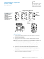
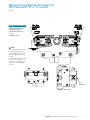
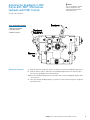
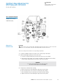
Hydraulic Neutral Adjustment
for HPV Pumps
Note
This Service Bulletin is valid for
HPV pumps controls, except
the “M1” control. For HPV
pumps with "M1" Control, refer
to pages 9-10 for the hydraulic
neutral adjustment instructions.
Set Up and Procedure
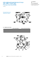
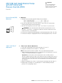
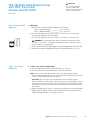
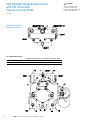
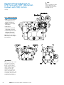
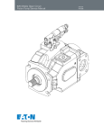
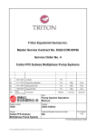
Hydraulic Neutral Adjustment
14.75
Z
Tools / Equipment Required
• Two (2) 0-600 psi pressure
gauges or transducers
Ms
Solenoid
• 16mm wrench
(optional: adjustable wrench)
Y
• Digital calipers
(optional: depth micrometers)
• Hammer and punch
H1 Control
E1 Control
E2 Control
Hydraulic
Neutral
Adjustment
M2P Control
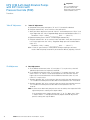
Adjustment Procedure:
1. Install the 0-600 psi pressure gauges into gauge ports "Mp" and "Ms" to measure
work-port pressures "P" and "S".
2. Set the input speed to high idle.
3. With the pump in neutral, measure the pressure difference between work-ports
"P" and "S".
Note: Pump in neutral means no control pressure or current supplied to the controls. For
M2P controls, the lever must be in neutral position.
a. If the maximum pressure difference is 29 psi (2 bar) or less, then adjustment to
the hydraulic neutral is NOT required, Remove all gauges from the pump.
b. If the maximum pressure difference is greater than 29 psi (2 bar), then go to step #4.
4. Loosen the Spanner Nut with the hammer and punch.
5. Using a 16mm wrench and the digital calipers, adjust the Hydraulic Neutral
Adjustment to 14.75mm as illustrated in the sketch above.
6. Repeat steps #2 and #3. Continue to make small adjustments to the Hydraulic
Neutral Adjustment until the pressure difference between work-ports "P" and "S" is
less than 29 psi.
7. Secure the Hydraulic Neutral Adjustment by tightening the Spanner Nut once all
settings are final. Remove all gauges from the pump.
EATON Duraforce HPV Service Manual E-PUPI-TS020-E July 2012
3
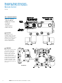
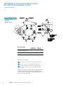
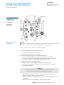
Regulation Begin Adjustment
for HPV With Electro-Hydraulic
Remote Control
Set Up
Tools / Equipment Required
• Multi-meter (capable of
reading 0 to 1000 mA)
• 0-6000 psi pressure gauge
or transducer
• 13mm offset
closed-end wrench
• Hammer and punch
Important
AFTER adjusting the
regulation begin, you must
reset the pump maximum
displacement setting. Follow
the instructions on pages
7-8 to reset the pump
maximum displacement.
WARNING
If performing this procedure
on a vehicle, care must
be taken. The pump will
be put on stroke during
this procedure, hence the
vehicle must be safely
elevated to allow the motor
to free-wheel. If this is NOT
possible, then the pump
workports "P" and "S" must
be short circuited to each
other to avoid movement of
the motor.
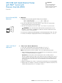
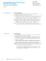
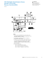
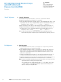
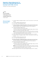
Ms
Solenoid
E2 Control
4
EATON Duraforce HPV Service Manual E-PUPI-TS020-E July 2012
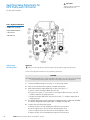
Regulation Begin Adjustment
for HPV With Electro-Hydraulic
Remote Control
Procedure for Right-Hand Rotation
Note
Prior to performing this
procedure, verify that the
hydraulic neutral on the pump
is correctly adjusted.
Adjustment Procedure
for Right-Hand Rotation
(CW) Pump:
1. Connect the multi-meter to measure current at solenoid “My”.
2. Install the 0-6000 psi gauge into gauge port "Mp".
3. Set the pump input speed to high idle.
4. For E2 controls, make sure that Ms Solenoid is energized.
a. 1.82A (12VDC)
b. 1.10A (24VDC)
5. While simultaneously monitoring the gauge and multi-meter, slowly energize
solenoid "My". Note the current on the multi-meter when you first see pressure
increase at port "Mp". This is the regulation begin setting for workport "P".
6. To Adjust the Regulation Begin Setting:
a. Use the hammer and punch to loosen "Spanner Nut #2".
b. U
se the 13mm wrench on "Locking Nut #2" to adjust "Regulation Begin Cup #2".
Turn it IN to increase the regulation begin setting or turn it OUT to decrease it.
c. Use the hammer and punch to tighten "Spanner Nut #2".
d. Repeat steps #3 through #5 to verify that the regulation begin setting is:
Control Range: A (2-8bar) B (4-10bar) C(4-16bar)
Regulation Begin for 12 VDC: 350 mA 450 mA 450 mA
Regulation Begin for 24 VDC: 175 mA 225 mA 225 mA
7. Repeat steps #1 through #6 for solenoid “Mz” and gauge port “Ms” to adjust the
regulation begin setting for workport “S”.
Note: Adjustments should be made to “Regulation Begin Cup #1”
EATON Duraforce HPV Service Manual E-PUPI-TS020-E July 2012
5
Regulation Begin Adjustment
for HPV With Electro-Hydraulic
Remote Control
Procedure for Left-Hand Rotation
Note
Prior to performing this
procedure, verify that the
hydraulic neutral on the pump
is correctly adjusted.
Adjustment Procedure
for Left-Hand Rotation
(CCW) Pump:
1. Connect the multi-meter to measure current at solenoid “Mz”.
2. Install the 0-6000 psi gauge into gauge port "Mp".
3. Set the pump input speed to high idle.
4. For E2 controls, make sure that Ms Solenoid is energized.
a. 1.82A (12VDC)
b. 1.10A (24VDC)
5. While simultaneously monitoring the gauge and multi-meter, slowly energize
solenoid "Mz". Note the current on the multi-meter when you first see pressure
increase at port "Mp". This is the regulation begin setting for workport "P".
6. To Adjust the Regulation Begin Setting:
a. Use the hammer and punch to loosen "Spanner Nut #1".
b. U
se the 13mm wrench on "Locking Nut #1" to adjust "Regulation Begin Cup #1".
Turn it IN to increase the regulation begin setting or turn it OUT to decrease it.
c. Use the hammer and punch to tighten "Spanner Nut #1".
d. Repeat steps #3 through #5 to verify that the regulation begin setting is:
Control Range: A (2-8bar) B (4-10bar) C(4-16bar)
Regulation Begin for 12 VDC: 350 mA 450 mA 450 mA
Regulation Begin for 24 VDC: 175 mA 225 mA 225 mA
7. Repeat steps #1 through #6 for solenoid “My” and gauge port “Ms” to adjust the
regulation begin setting for workport “S”.
Note: Adjustments should be made to “Regulation Begin Cup #2”.
6
EATON Duraforce HPV Service Manual E-PUPI-TS020-E July 2012
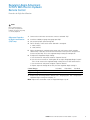
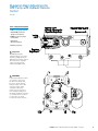
Maximum Flow Adjustment Procedure for
HPV Pumps with “H” or “E” Controls
Set Up
Tools / Equipment Required
• 0-600 psi pressure gauge or
transducer (optional)
• 13mm offset closed-end
wrench
• 4mm Allen wrench
Note
This Service Bulletin is valid
for HPV pumps with either
"H" (Hydraulic Remote) or "E"
(Electro-Hydraulic Remote)
Controls
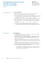
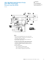
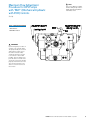
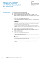
The drawing below illustrates
an "H1" Control, but the
information is also valid for
“H1P”, “E1”. “E1P, and “E2”
Controls.
Ms
Solenoid
E2 Control
EATON Duraforce HPV Service Manual E-PUPI-TS020-E July 2012
7
Maximum Flow Adjustment Procedure for
HPV Pumps with “H” or “E” Controls
Adjustment Procedure
WARNING
If performing this procedure on a vehicle, care must be
taken. The pump will be put on stroke during this procedure;
hence the vehicle must be safely elevated to allow the
motor to free-wheel. If this is NOT possible, then the pump
work-ports "P" and "S" must be short circuited to each other.
Install a properly sized flow-meter in the short circuit line
between "P" and "S" to avoid movement of the motor.
1
(Optional) Install the 0-600 psi gauge into gauge port "Y".
7
(Optional) Install the 0-600 psi gauge into gauge port "Z".
2
Set the input speed to high idle.
8
Set the input speed to high idle.
3
For E2 Controls, make sure that Ms Solenoid is
energized.
9
For E2 Controls, Make sure that Ms Solenoid is
energized.
a. 1.82A (12VDC)
a. 1.82A (12VDC)
b. 1.10A (24VDC)
b. 1.10A (24VDC)
4
Supply full control pressure to port "Y" or full current
to solenoid "My". (Optional) Confirm that the pressure
at port "Y" is adequate to put the pump at full
displacement.
5
Measure the rotational speed of the motor, the
wheel, the gearbox, etc. and calculate if the pump
is supplying enough flow. If using a short circuit line,
measure the flow from the flow-meter.
6
To Adjust the Maximum Flow:
a. Use the 13mm wrench to loosen "Locking Nut #2".
10
11
12
WARNING
c. O
nce the desired maximum flow has been
acquired, hold the flow adjustment stud stationary
with the 4mm Allen wrench and tighten the
locking nut with the 13mm wrench (the proper
torque for the locking nut is 10 ft-lb [14 N-m].
8
EATON Duraforce HPV Service Manual E-PUPI-TS020-E July 2012
Measure the rotational speed of the motor, the
wheel, the gearbox, etc. and calculate if the pump is
supplying enough flow. If using the short circuit line,
measure the flow from the flow-meter.
To Adjust the Maximum Flow:
a. Use the 13mm wrench to loosen "Locking Nut #1".
b. U
se the 4mm Allen wrench to turn "Max. Flow
Adjustment Stud #1". Turn it IN to decrease the
maximum flow or turn it OUT to increase it.
b. U
se the 4mm Allen wrench to turn "Max. Flow
Adjustment Stud #2". Turn it IN to decrease the
maximum flow or turn it OUT to increase it..
The flow adjustment stud is NOT mechanically
restricted from being removed completely from
the pump. Care should be taken when turning
the flow adjustment stud OUT. DO NOT turn
the adjustment stud OUT more than 26mm as
illustrated on previous page.
Supply full control pressure to port "Z" or full current
to solenoid "Mz". (Optional) Confirm that the pressure
at port "Z" is adequate to put the pump at full
displacement.
WARNING
The flow adjustment stud is NOT mechanically restricted
from being removed completely from the pump. Care should
be taken when turning the flow adjustment stud OUT. DO
NOT turn the adjustment stud OUT more than 26mm as
illustrated on previous page.
13
Once the desired maximum flow has been
acquired, hold the flow adjustment stud stationary
with the 4mm Allen wrench and tighten the locking
nut with the 13mm wrench (the proper torque for
the locking nut is 10 ft-lb [14 N-m]).
HPV Hydraulic Neutral Adjustment
Procedure for M1 (Cam) Control
Set Up
Tools / Equipment Required
• Two (2) high pressure gauges
or transducers (6000 psi)
• 16mm wrench (optional:
adjustable wrench)
• Special pointing device
provided by Eaton
• Digital calipers
(optional: depth micrometers)
• Hammer and punch
WARNING
If performing this procedure
on a vehicle, care must be
taken. The pump will be
put on stroke during this
procedure; hence the vehicle
must be safely elevated to
allow the motor to free-wheel.
If this is NOT possible, then
clear all personnel from the
machine to avoid injury when
the machine moves.
Note:
The maximum displacement on this control must be set prior to using this Service
Bulletin. Please follow all steps on page 38 before continuing with this Service Bulletin.
Note:
The following steps are ONLY to be carried out by those individuals trained on this
particular procedure.
EATON Duraforce HPV Service Manual E-PUPI-TS020-E July 2012
9
HPV Hydraulic Neutral Adjustment
Procedure for M1 (Cam) Control
Procedure
Adjustment Procedure:
1. Install the two high pressure gauges to measure work-port pressure "P" and "S".
2. Orient the alignment marks so that they are parallel with the centerline of the
hydraulic neutral adjustment as illustrated above.
3. Set the input speed to high idle.
4. Measure the pressure difference between work-ports "P" and "S".
• If the maximum pressure difference is 29 psi (2 bar) or less, then adjustment to
the hydraulic neutral is NOT required - Remove all gauges from the pump.
• If the maximum pressure difference is greater than 29 psi (2 bar), then go to step #5.
5. Loosen the spanner nut on the Hydraulic Neutral Adjustment with the hammer
and punch.
6. Using a 16mm wrench and the digital calipers, adjust the hydraulic neutral
adjustment to 14.75mm as illustrated in the sketch above.
7. Install the special pointing device onto the cam lever.
8. With the pump aligned in neutral (as described in step #2), make a small mark on
the pump control (either with a pen or a magic-marker) where the pointer of the
pointing device is pointing.
9. Move the control lever in one direction until the pressure difference between the
work-ports "P" and "S" is 580 psi (40 bar). Make a small mark where the pointer is.
10. Move the control lever in the opposite direction until the pressure difference is 580
psi (40 bar). Make a small mark where the pointer is.
11. The initial mark made in step #8 should be directly in the middle of the other two
marks made in steps #9 and #10. If not, make a very small adjustment to the
hydraulic neutral adjustment. Erase all previous marks and repeat steps #8 through
#11 until the initial mark is directly in the middle of the other two marks.
12. Repeat steps #1 through #4 and verify that the maximum pressure difference
between work-ports "P" and "S" is 29 psi (2 bar) or less. If not, confirm gauges (or
transducers) are calibrated and functioning correctly. You may need to repeat the
entire procedure to insure the hydraulic neutral is set correctly.
13. Secure the Hydraulic Neutral Adjustment by tightening the spanner nut. Remove all
gauges from the pump.
10
EATON Duraforce HPV Service Manual E-PUPI-TS020-E July 2012
HPV CCW (Left Hand) Rotation Pumps
with “M2P” Control with
Pressure Override (POR)
Important
This is a "field adjustment"
procedure valid for HPV
pumps with CCW (Left-Hand)
rotation and M2P control.
Set Up
Notes:
• Since the oil is being bled over the main relief valves
during this procedure, monitor the oil temperature in the
main loop to avoid over heating.
• Oil Temperature Limitations for Eaton Components:
(-4)°F to 194°F (-20)°C to 90°C
• Changes to any pump setting, control supply pressure,
or system hardware after the POR has been adjusted
could alter the performance of the POR. It may be
necessary to readjust the POR to compensate for any
of these changes.
• Recommended Gauges:
- (Qty 1) 7,500 psi Liquid-filled gauge
(Qty 2 recommended for ease of testing)
- (Qty 1) 0-200 psi np-gauge or np-transducer
EATON Duraforce HPV Service Manual E-PUPI-TS020-E July 2012
11
HPV CCW (Left Hand) Rotation Pumps
with “M2P” Control with
Pressure Override (POR)
Set Up
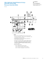
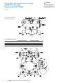
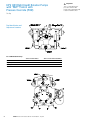
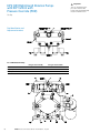
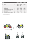
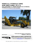
Port Identification and
Adjustment Locations:
For a CCW Rotation Pump:
12
Turn Lever Clockwise Turn Lever Counter-Clockwise
Control Pressure At Port Pump Output Pressure at Port Must Adjust Z P Valve I Y
S
Valve II
EATON Duraforce HPV Service Manual E-PUPI-TS020-E July 2012
Important
This is a "field adjustment"
procedure valid for HPV
pumps with CCW (Left-Hand)
rotation and M2P control.
HPV CCW (Left Hand) Rotation Pumps
with “M2P” Control with
Pressure Override (POR)
Important
This is a "field adjustment"
procedure valid for HPV
pumps with CCW (Left-Hand)
rotation and M2P control.
Procedure
Pressure Override (POR)
Adjustment:
1. POR Setup:
A. Measure and record the regulation begin pressures below.
“nPy-z” Regulation Begin:_____________ psi…..(value “a”)
“nPz-y” Regulation Begin:_____________ psi…..(value “b”)
B. Turn OUT the adjustment screw for “Valve III” all the way (it is mechanically
restricted from being removed completely).
C. Turn OUT the adjustment screw for “Valve I” and “Valve II” by 3-4 full turns.
Warning: Care should be taken NOT to remove the adjustment screw
in “Valve I” and “Valve II” completely. Do NOT turn OUT the adjustment screw
more than 19mm as illustrated left.
“Valve I” and “Valve II”
Adjustments:
D. C
onnect the 0-7500 psi liquid-filled gauges to work port gauge ports “Mp” and “Ms”.
E. Connect the 0-200 psi np-gauge/transducer to control gauge ports “Y” and “Z”.
2. “Valve I” and “Valve II” Adjustments:
A. Close OFF or block both of the pump work ports “P” and “S”.
B. Turn the control lever Counter-Clockwise (CCW) fully and hold it.
Note: System pressure will be unstable - This is an expected pump reaction.
C. While monitoring work port pressure “S”, SLOWLY turn the adjustment screw for
“Valve II” IN until the pressure just stabilizes.
Important: You must slowly turn the adjustment screw in ONLY until the
pressure stabilizes and then stop. If you continue to turn the adjustment screw in,
system pressure will continue to increase and an unnecessary amount of oil will
be forced over the main relief valve, thus the operation of the POR will become
less efficient.
D. Tighten the locking nut on “Valve II” and return the control lever to its neutral position.
E. Repeat steps “A” through “D” but turn the control lever Clockwise (CW) fully and
monitor work port pressure “P” and adjust “Valve I”.
EATON Duraforce HPV Service Manual E-PUPI-TS020-E July 2012
13
HPV CCW (Left Hand) Rotation Pumps
with “M2P” Control with
Pressure Override (POR)
Important
This is a "field adjustment"
procedure valid for HPV
pumps with CCW (Left-Hand)
rotation and M2P control.
Procedure
“Valve III” Adjustment:
3. “Valve III” Adjustment:
A. Keep both of the pump work ports (“P” and “S”) closed off or blocked.
B. Turn the control lever Counter-Clockwise (CCW) fully and hold it.
C. Slowly turn IN the adjustment screw for “Valve III” until control pressure “nPy-z” is 10
-15 psi higher than the “nPy-z” Regulation Begin pressure recorded above (value “a”).
D. Tighten the locking nut on “Valve III” and return the control lever to its neutral position.
E. Turn the control lever Clockwise (CW) fully and hold it. Verify that the pressure
is 10 - 15 psi higher than the “Pz-y” Regulation Begin pressure recorded above
(value “b”).
Final Adjustment:
Record the “nPy-z” setting: _____________ psid……….(value “e”)
Record the “nPz-y” setting: _____________ psid……….(value “f”)
Hint: If “Valve III” gets too hot, it will be difficult to adjust and/or get consistent
results. Allow the pump to cool off if you encounter difficulty adjusting “Valve III”.
4. Final Adjustment:
A. IF the difference between (value “e”) and (value “f”) is 5 psi or less, then NO
additional adjustments are required to the POR.
B. IF the difference between (value “e”) and (value “f”) is greater than 5 psi, then
either “Valve I” or “Valve II” needs to be backed out. The side which has the
higher value must be backed out until the difference between (value “e”) and
(value “f”) is 5 psi or less.
C. Turn the control lever Counter-Clockwise (CCW) fully and verify that work port
pressure “S” is stable and control pressure does NOT increase/decrease for ~10
seconds.
D. Turn the control lever Clockwise (CW) fully and verify that work port pressure “P”
is stable and control pressure does NOT increase/decrease for ~10 seconds.
Note: If either one or both work port pressures are not stable, then repeat the POR
adjustment process starting with step #1 above.
If the control pressure changes during steps “C” or “D” above, then “Valve
I” and/or “Valve II” is not adjusted correctly. Repeat the POR adjustment
process starting with step #1 above.
14
EATON Duraforce HPV Service Manual E-PUPI-TS020-E July 2012
HPV CCW (Left-Hand) Rotation Pumps
with E1P Control with
Pressure Override (POR)
Important
This is a "field adjustment"
procedure valid for HPV
pumps with CCW (Left-Hand)
rotation and E1P Control
Set Up
Notes:
• Since the oil is being bled over the main relief valves
during this procedure, monitor the oil temperature in the
main loop to avoid over heating.
• Oil Temperature Limitations for Eaton Components:
(-4)°F to 194°F (-20)°C to 90°C
• Changes to any pump setting, control supply pressure,
or system hardware after the POR has been adjusted
could alter the performance of the POR. It may be
necessary to readjust the POR to compensate for any
of these changes.
• Recommended Gauges:
- (Qty 1) 7,500 psi Liquid-filled gauge
(Qty 2 recommended for ease of testing)
- (Qty 1) 0-200 psi np-gauge or np-transducer
EATON Duraforce HPV Service Manual E-PUPI-TS020-E July 2012
15
HPV CCW (Left-Hand) Rotation Pumps
with E1P Control with
Pressure Override (POR)
Set Up
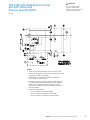
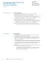
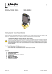
Port Identification and
Adjustment Locations:
For a CCW Rotation Pump:
16
Energize Solenoid My Energize Solenoid Mz
Control Pressure At Port Pump Output Pressure at Port Must Adjust Y S Valve II Z
P
Valve I
EATON Duraforce HPV Service Manual E-PUPI-TS020-E July 2012
Important
This is a "field adjustment"
procedure valid for HPV
pumps with CCW (Left-Hand)
rotation and E1P Control
HPV CCW (Left-Hand) Rotation Pumps
with E1P Control with
Pressure Override (POR)
Important
This is a "field adjustment"
procedure valid for HPV
pumps with CCW (Left-Hand)
rotation and E1P Control
Procedure
Pressure Override (POR)
Adjustment:
1. POR Setup:
A. Measure and record the regulation begin pressures below.
“nPy-z” Regulation Begin:_____________ psi…..(value “a”)
“nPz-y” Regulation Begin:_____________ psi…..(value “b”)
B. Turn OUT the adjustment screw for “Valve III” all the way (it is mechanically
restricted from being removed completely).
C. Turn OUT the adjustment screw for “Valve I” and “Valve II” by 3-4 full turns.
Warning: Care should be taken NOT to remove the adjustment screw
in “Valve I” and “Valve II” completely. Do NOT turn OUT the adjustment screw
more than 19mm as illustrated left.
“Valve I” and “Valve II”
Adjustments:
D. C
onnect the 0-7500 psi liquid-filled gauges to work port gauge ports “Mp” and “Ms”.
E. Connect the 0-200 psi np-gauge/transducer to control gauge ports “Y” and “Z”.
2. “Valve I” and “Valve II” Adjustments:
A. Close OFF or block both of the pump work ports “P” and “S”.
B. Energize solenoid “My” to its maximum value and hold it.
Note: System pressure will be unstable - This is an expected pump reaction.
C. While monitoring work port pressure “S”, SLOWLY turn the adjustment screw for
“Valve II” IN until the pressure just stabilizes.
Important: You must slowly turn the adjustment screw in ONLY until the
pressure stabilizes and then stop. If you continue to turn the adjustment screw in,
system pressure will continue to increase and an unnecessary amount of oil will
be forced over the main relief valve, thus the operation of the POR will become
less efficient.
D. Tighten the locking nut on “Valve II” and de-energize solenoid “My”.
E. Repeat steps “A” through “D” for solenoid “Mz” while monitoring work port pressure
“P” and adjusting “Valve I”.
EATON Duraforce HPV Service Manual E-PUPI-TS020-E July 2012
17
HPV CCW (Left-Hand) Rotation Pumps
with E1P Control with
Pressure Override (POR)
Important
This is a "field adjustment"
procedure valid for HPV
pumps with CCW (Left-Hand)
rotation and E1P Control
Procedure
“Valve III” Adjustment:
3. “Valve III” Adjustment:
A. Keep both of the pump work ports (“P” and “S”) closed off or blocked.
B. Energize solenoid “My” to its maximum value and hold it.
C. Slowly turn IN the adjustment screw for “Valve III” until control pressure “nPy-z” is 10
-15 psi higher than the “nPy-z” Regulation Begin pressure recorded above (value “a”).
D. Tighten the locking nut on “Valve III” and de-energize solenoid “My”.
E. Energize solenoid “Mz” to its maximum value and hold it. Verify that the pressure
is 10 -15 psi higher than the “nPz-y” Regulation Begin pressure recorded above
(value “b”).
Final Adjustment:
Record the “nPy-z” setting: _____________ psid……….(value “e”)
Record the “nPz-y” setting: _____________ psid……….(value “f”)
Hint: If “Valve III” gets too hot, it will be difficult to adjust and/or get consistent
results. Allow the pump to cool off if you encounter difficulty adjusting “Valve III”.
4. Final Adjustment:
A. IF the difference between (value “e”) and (value “f”) is 5 psi or less, then NO
additional adjustments are required to the POR.
B. IF the difference between (value “e”) and (value “f”) is greater than 5 psi, then
either “Valve I” or “Valve II” needs to be backed out. The side which has the
higher value must be backed out until the difference between (value “e”) and
(value “f”) is 5 psi or less.
C. E
nergize solenoid “My” to its maximum value and verify that work port pressure
“S” is stable and control pressure does NOT increase/decrease for ~10 seconds.
D. E
nergize solenoid “Mz” to its maximum value and verify that work port pressure
“P” is stable and control pressure does NOT increase/decrease for ~10
seconds.
Note: If either one or both work port pressures are not stable, then repeat the POR
adjustment process starting with step #1 above.
If the control pressure changes during steps “C” or “D” above, then “Valve
I” and/or “Valve II” is not adjusted correctly. Repeat the POR adjustment
process starting with step #1 above.
18
EATON Duraforce HPV Service Manual E-PUPI-TS020-E July 2012
HPV CCW (Left Hand) Rotation Pumps
with H1P Control with
Pressure Override (POR)
Important
This is a "field adjustment"
procedure valid for HPV
pumps with CCW (Left-Hand)
rotation and H1P Control
Set Up
Notes:
• Since the oil is being bled over the main relief valves
during this procedure, monitor the oil temperature in the
main loop to avoid over heating.
• Oil Temperature Limitations for Eaton Components:
(-4)°F to 194°F (-20)°C to 90°C
• Changes to any pump setting, control supply pressure,
or system hardware after the POR has been adjusted
could alter the performance of the POR. It may be
necessary to readjust the POR to compensate for any
of these changes.
• Recommended Gauges:
- (Qty 1) 7,500 psi Liquid-filled gauge
(Qty 2 recommended for ease of testing)
- (Qty 1) 0-200 psi np-gauge or np-transducer
EATON Duraforce HPV Service Manual E-PUPI-TS020-E July 2012
19
HPV CCW (Left Hand) Rotation Pumps
with H1P Control with
Pressure Override (POR)
Set Up
Port Identification and
Adjustment Locations:
For a CCW Rotation Pump:
20
Control Pressure Into Port Y Control Pressure Into Port Z
Pump Output Pressure At Port Must Adjust S Valve II P
Valve I
EATON Duraforce HPV Service Manual E-PUPI-TS020-E July 2012
Important
This is a "field adjustment"
procedure valid for HPV
pumps with CCW (Left-Hand)
rotation and H1P Control
HPV CCW (Left Hand) Rotation Pumps
with H1P Control with
Pressure Override (POR)
Important
This is a "field adjustment"
procedure valid for HPV
pumps with CCW (Left-Hand)
rotation and H1P Control
Procedure
Pressure Override (POR)
Adjustment:
1. POR Setup:
A. Measure and record the regulation begin pressures below.
“nPy-z” Regulation Begin:_____________ psi…..(value “a”)
“nPz-y” Regulation Begin:_____________ psi…..(value “b”)
B. Turn OUT the adjustment screw for “Valve III” all the way (it is mechanically
restricted from being removed completely).
C. Turn OUT the adjustment screw for “Valve I” and “Valve II” by 3-4 full turns.
Warning: Care should be taken NOT to remove the adjustment screw
in “Valve I” and “Valve II” completely. Do NOT turn OUT the adjustment screw
more than 19mm as illustrated left.
“Valve I” and “Valve II”
Adjustments:
D. C
onnect the 0-7500 psi liquid-filled gauges to work port gauge ports “Mp” and “Ms”.
E. Connect the 0-200 psi np-gauge/transducer to control gauge ports“My” and “Mz”.
2. “Valve I” and “Valve II” Adjustments:
A. Close OFF or block both of the pump work ports “P” and “S”.
B. Supply full control pressure into port “Y” and hold it.
Note: System pressure will be unstable - This is an expected pump reaction.
C. While monitoring work port pressure “S”, SLOWLY turn the adjustment screw for
“Valve II” IN until the pressure just stabilizes.
Important: You must slowly turn the adjustment screw in ONLY until the
pressure stabilizes and then stop. If you continue to turn the adjustment screw in,
system pressure will continue to increase and an unnecessary amount of oil will
be forced over the main relief valve, thus the operation of the POR will become
less efficient.
D. Tighten the locking nut on “Valve II” and remove the control pressure from port “Y”.
E. Repeat steps “A” through “D” for control port “Z” while monitoring work port
pressure “P” and adjusting “Valve I”.
EATON Duraforce HPV Service Manual E-PUPI-TS020-E July 2012
21
HPV CCW (Left Hand) Rotation Pumps
with H1P Control with
Pressure Override (POR)
Important
This is a "field adjustment"
procedure valid for HPV
pumps with CCW (Left-Hand)
rotation and H1P Control
Procedure
“Valve III” Adjustment:
3. “Valve III” Adjustment:
A. Keep both of the pump work ports (“P” and “S”) closed off or blocked.
B. Supply full control pressure into port “Y” and hold it.
C. Slowly turn IN the adjustment screw for “Valve III” until control pressure “nPy-z” is 10
-15 psi higher than the “nPy-z” Regulation Begin pressure recorded above (value “a”).
D. Tighten the locking nut on “Valve III” and remove the control pressure from port “Y”.
E. Supply full control pressure into port “Z” and hold it. Verify that the pressure is 10 - 15
psi higher than the “nPz-y” Regulation Begin pressure recorded above (value “b”).
Final Adjustment:
Record the “nPy-z” setting: _____________ psid……….(value “e”)
Record the “nPz-y” setting: _____________ psid……….(value “f”)
Hint: If “Valve III” gets too hot, it will be difficult to adjust and/or get consistent
results. Allow the pump to cool off if you encounter difficulty adjusting “Valve III”.
4. Final Adjustment:
A. IF the difference between (value “e”) and (value “f”) is 5 psi or less, then NO
additional adjustments are required to the POR.
B. IF the difference between (value “e”) and (value “f”) is greater than 5 psi, then
either “Valve I” or “Valve II” needs to be backed out. The side which has the
higher value must be backed out until the difference between (value “e”) and
(value “f”) is 5 psi or less.
C. S
upply full control pressure into port “Y” and verify that work port pressure “S”
is stable and control pressure does NOT increase/decrease for ~10 seconds.
D. S
upply full control pressure into port “Z” and verify that work port pressure “P” is stable and control pressure does NOT increase/decrease for ~10 seconds.
Note: If either one or both work port pressures are not stable, then repeat the POR
adjustment process starting with step #1 above.
If the control pressure changes during steps “C” or “D” above, then “Valve
I” and/or “Valve II” is not adjusted correctly. Repeat the POR adjustment
process starting with step #1 above.
22
EATON Duraforce HPV Service Manual E-PUPI-TS020-E July 2012
HPV CW (Right Hand) Rotation Pumps
with “M2P” Control with
Pressure Override (POR)
Important
This is a "field adjustment"
procedure valid for HPV
pumps with CW (Right-Hand)
rotation and M2P control
Set Up
Notes:
• Since the oil is being bled over the main relief valves
during this procedure, monitor the oil temperature in the
main loop to avoid over heating.
• Oil Temperature Limitations for Eaton Components:
(-4)°F to 194°F (-20)°C to 90°C
• Changes to any pump setting, control supply pressure,
or system hardware after the POR has been adjusted
could alter the performance of the POR. It may be
necessary to readjust the POR to compensate for any
of these changes.
• Recommended Gauges:
- (Qty 1) 7,500 psi Liquid-filled gauge
(Qty 2 recommended for ease of testing)
- (Qty 1) 0-200 psi np-gauge or np-transducer
EATON Duraforce HPV Service Manual E-PUPI-TS020-E July 2012
23
HPV CW (Right Hand) Rotation Pumps
with “M2P” Control with
Pressure Override (POR)
Set Up
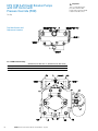
Port Identification and
Adjustment Locations:
For a CW Rotation Pump:
24
Turn Lever Clockwise Turn Lever Counter-Clockwise
Control Pressure At Port Pump Output Pressure at Port Must Adjust Z S
Valve II Y
P
Valve I
EATON Duraforce HPV Service Manual E-PUPI-TS020-E July 2012
Important
This is a "field adjustment"
procedure valid for HPV
pumps with CW (Right-Hand)
rotation and M2P control
HPV CW (Right Hand) Rotation Pumps
with “M2P” Control with
Pressure Override (POR)
Important
This is a "field adjustment"
procedure valid for HPV
pumps with CW (Right-Hand)
rotation and M2P control
Procedure
Pressure Override (POR)
Adjustment:
1. POR Setup:
A. Measure and record the regulation begin pressures below.
“nPy-z” Regulation Begin:_____________ psi…..(value “a”)
“nPz-y” Regulation Begin:_____________ psi…..(value “b”)
B. Turn OUT the adjustment screw for “Valve III” all the way (it is mechanically
restricted from being removed completely).
C. Turn OUT the adjustment screw for “Valve I” and “Valve II” by 3-4 full turns.
Warning: Care should be taken NOT to remove the adjustment screw
in “Valve I” and “Valve II” completely. Do NOT turn OUT the adjustment screw
more than 19mm as illustrated left.
“Valve I” and “Valve II”
Adjustments:
D. C
onnect the 0-7500 psi liquid-filled gauges to work port gauge ports “Mp” and “Ms”.
E. Connect the 0-200 psi np-gauge/transducer to control gauge ports“Y” and “Z”.
2. “Valve I” and “Valve II” Adjustments:
A. Close OFF or block both of the pump work ports “P” and “S”.
B. Turn the control lever Counter-Clockwise (CCW) fully and hold it.
Note: System pressure will be unstable - This is an expected pump reaction.
C. While monitoring work port pressure “P”, SLOWLY turn the adjustment screw for
“Valve I” IN until the pressure just stabilizes.
Important: You must slowly turn the adjustment screw in ONLY until the
pressure stabilizes and then stop. If you continue to turn the adjustment screw in,
system pressure will continue to increase and an unnecessary amount of oil will
be forced over the main relief valve, thus the operation of the POR will become
less efficient.
D. Tighten the locking nut on “Valve I” and return the control lever to its neutral position.
E. Repeat steps “A” through “D” but turn the control lever Clockwise (CW) fully and
monitor work port pressure “S” and adjust “Valve II”.
EATON Duraforce HPV Service Manual E-PUPI-TS020-E July 2012
25
HPV CW (Right Hand) Rotation Pumps
with “M2P” Control with
Pressure Override (POR)
Important
This is a "field adjustment"
procedure valid for HPV
pumps with CW (Right-Hand)
rotation and M2P control
Procedure
“Valve III” Adjustment:
3. “Valve III” Adjustment:
A. Keep both of the pump work ports (“P” and “S”) closed off or blocked.
B. Turn the control lever Counter-Clockwise (CCW) fully and hold it.
C. Slowly turn IN the adjustment screw for “Valve III” until control pressure “nPy-z” is 10
-15 psi higher than the “nPy-z” Regulation Begin pressure recorded above (value “a”).
D. Tighten the locking nut on “Valve III” and return the control lever to its neutral position.
E. Turn the control lever Clockwise (CW) fully and hold it. Verify that the pressure is 10 - 15
psi higher than the “nPz-y” Regulation Begin pressure recorded above (value “b”).
Final Adjustment:
Record the “nPy-z” setting: _____________ psid……….(value “e”)
Record the “nPz-y” setting: _____________ psid……….(value “f”)
Hint: If “Valve III” gets too hot, it will be difficult to adjust and/or get consistent
results. Allow the pump to cool off if you encounter difficulty adjusting “Valve III”.
4. Final Adjustment:
A. IF the difference between (value “e”) and (value “f”) is 5 psi or less, then NO
additional adjustments are required to the POR.
B. IF the difference between (value “e”) and (value “f”) is greater than 5 psi, then
either “Valve I” or “Valve II” needs to be backed out. The side which has the
higher value must be backed out until the difference between (value “e”) and
(value “f”) is 5 psi or less.
C. Turn the control lever Counter-Clockwise (CCW) fully and verify that work port
pressure “P” is stable and control pressure does NOT increase/decrease for ~10
seconds.
D. Turn the control lever Clockwise (CW) fully and verify that work port pressure “S”
is stable and control pressure does NOT increase/decrease for ~10 seconds.
Note: If either one or both work port pressures are not stable, then repeat the POR
adjustment process starting with step #1 above.
If the control pressure changes during steps “C” or “D” above, then “Valve
I” and/or “Valve II” is not adjusted correctly. Repeat the POR adjustment
process starting with step #1 above.
26
EATON Duraforce HPV Service Manual E-PUPI-TS020-E July 2012
HPV CW (Right-Hand) Rotation Pumps
with E1P Control with
Pressure Override (POR)
Important
This is a "field adjustment"
procedure valid for HPV
pumps with CW (Right-Hand)
rotation and E1P Control
Set Up
Notes:
• Since the oil is being bled over the main relief valves
during this procedure, monitor the oil temperature in the
main loop to avoid over heating.
• Oil Temperature Limitations for Eaton Components:
(-4)°F to 194°F (-20)°C to 90°C
• Changes to any pump setting, control supply pressure,
or system hardware after the POR has been adjusted
could alter the performance of the POR. It may be
necessary to readjust the POR to compensate for any
of these changes.
• Recommended Gauges:
- (Qty 1) 7,500 psi Liquid-filled gauge
(Qty 2 recommended for ease of testing)
- (Qty 1) 0-200 psi np-gauge or np-transducer
EATON Duraforce HPV Service Manual E-PUPI-TS020-E July 2012
27
HPV CW (Right-Hand) Rotation Pumps
with E1P Control with
Pressure Override (POR)
Set Up
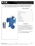
Port Identification and
Adjustment Locations:
For a CW Rotation Pump:
28
Energize Solenoid My Energize Solenoid Mz
Control Pressure At Port Pump Output Pressure at Port Must Adjust Y
P Valve I
Z
S
Valve II
EATON Duraforce HPV Service Manual E-PUPI-TS020-E July 2012
Important
This is a "field adjustment"
procedure valid for HPV
pumps with CW (Right-Hand)
rotation and E1P Control
HPV CW (Right-Hand) Rotation Pumps
with E1P Control with
Pressure Override (POR)
Important
This is a "field adjustment"
procedure valid for HPV
pumps with CW (Right-Hand)
rotation and E1P Control
Procedure
Pressure Override (POR)
Adjustment:
1. POR Setup:
A. Measure and record the regulation begin pressures below.
“nPy-z” Regulation Begin:_____________ psi…..(value “a”)
“nPz-y” Regulation Begin:_____________ psi…..(value “b”)
B. Turn OUT the adjustment screw for “Valve III” all the way (it is mechanically
restricted from being removed completely).
C. Turn OUT the adjustment screw for “Valve I” and “Valve II” by 3-4 full turns.
Warning: Care should be taken NOT to remove the adjustment screw
in “Valve I” and “Valve II” completely. Do NOT turn OUT the adjustment screw
more than 19mm as illustrated left.
“Valve I” and “Valve II”
Adjustments:
D. C
onnect the 0-7500 psi liquid-filled gauges to work port gauge ports “Mp” and “Ms”.
E. Connect the 0-200 psi np-gauge/transducer to control gauge ports“Y” and “Z”.
2. “Valve I” and “Valve II” Adjustments:
A. Close OFF or block both of the pump work ports “P” and “S”.
B. Energize solenoid “My” to its maximum value and hold it.
Note: System pressure will be unstable - This is an expected pump reaction.
C. While monitoring work port pressure “P”, SLOWLY turn the adjustment screw for
“Valve I” IN until the pressure just stabilizes.
Important: You must slowly turn the adjustment screw in ONLY until the
pressure stabilizes and then stop. If you continue to turn the adjustment screw in,
system pressure will continue to increase and an unnecessary amount of oil will
be forced over the main relief valve, thus the operation of the POR will become
less efficient.
D. Tighten the locking nut on “Valve I” and de-energize solenoid “My”.
E. Repeat steps “A” through “D” for solenoid “Mz” while monitoring work port pressure
“S” and adjusting “Valve II”.
EATON Duraforce HPV Service Manual E-PUPI-TS020-E July 2012
29
HPV CW (Right-Hand) Rotation Pumps
with E1P Control with
Pressure Override (POR)
Important
This is a "field adjustment"
procedure valid for HPV
pumps with CW (Right-Hand)
rotation and E1P Control
Procedure
“Valve III” Adjustment:
3. “Valve III” Adjustment:
A. Keep both of the pump work ports (“P” and “S”) closed off or blocked.
B. Energize solenoid “My” to its maximum value and hold it.
C. Slowly turn IN the adjustment screw for “Valve III” until control pressure “nPy-z” is 10
-15 psi higher than the “nPy-z” Regulation Begin pressure recorded above (value “a”).
D. Tighten the locking nut on “Valve III” and de-energize solenoid “My”.
E. Energize solenoid “Mz” to its maximum value and hold it. Verify that the pressure is 10 15 psi higher than the “nPz-y” Regulation Begin pressure recorded above (value “b”).
Final Adjustment:
Record the “nPy-z” setting: _____________ psid……….(value “e”)
Record the “nPz-y” setting: _____________ psid……….(value “f”)
Hint: If “Valve III” gets too hot, it will be difficult to adjust and/or get consistent
results. Allow the pump to cool off if you encounter difficulty adjusting “Valve III”.
4. Final Adjustment:
A. IF the difference between (value “e”) and (value “f”) is 5 psi or less, then NO
additional adjustments are required to the POR.
B. IF the difference between (value “e”) and (value “f”) is greater than 5 psi, then
either “Valve I” or “Valve II” needs to be backed out. The side which has the
higher value must be backed out until the difference between (value “e”) and
(value “f”) is 5 psi or less.
C. E
nergize solenoid “My” to its maximum value and verify that work port pressure
“P” is stable and control pressure does NOT increase/decrease for ~10 seconds.
D. E
nergize solenoid “Mz” to its maximum value and verify that work port pressure
“S” is stable and control pressure does NOT increase/decrease for ~10
seconds.
Note: If either one or both work port pressures are not stable, then repeat the POR
adjustment process starting with step #1 above.
If the control pressure changes during steps “C” or “D” above, then “Valve
I” and/or “Valve II” is not adjusted correctly. Repeat the POR adjustment
process starting with step #1 above.
30
EATON Duraforce HPV Service Manual E-PUPI-TS020-E July 2012
HPV CW (Right Hand) Rotation Pumps
with H1P Control with
Pressure Override (POR)
Important
This is a "field adjustment"
procedure valid for HPV
pumps with CW (Right-Hand)
rotation and H1P Control
Set Up
Notes:
• Since the oil is being bled over the main relief valves
during this procedure, monitor the oil temperature in the
main loop to avoid over heating.
• Oil Temperature Limitations for Eaton Components:
(-4)°F to 194°F (-20)°C to 90°C
• Changes to any pump setting, control supply pressure,
or system hardware after the POR has been adjusted
could alter the performance of the POR. It may be
necessary to readjust the POR to compensate for any
of these changes.
• Recommended Gauges:
- (Qty 1) 7,500 psi Liquid-filled gauge
(Qty 2 recommended for ease of testing)
- (Qty 1) 0-200 psi np-gauge or np-transducer
EATON Duraforce HPV Service Manual E-PUPI-TS020-E July 2012
31
HPV CW (Right Hand) Rotation Pumps
with H1P Control with
Pressure Override (POR)
Set Up
Port Identification and
Adjustment Locations:
For a CW Rotation Pump:
32
Control Pressure Into Port Y Control Pressure Into Port Z
Pump Output Pressure At Port Must Adjust P Valve I
S
Valve II
EATON Duraforce HPV Service Manual E-PUPI-TS020-E July 2012
Important
This is a "field adjustment"
procedure valid for HPV
pumps with CW (Right-Hand)
rotation and H1P Control
HPV CW (Right Hand) Rotation Pumps
with H1P Control with
Pressure Override (POR)
Important
This is a "field adjustment"
procedure valid for HPV
pumps with CW (Right-Hand)
rotation and H1P Control
Procedure
Pressure Override (POR)
Adjustment:
1. POR Setup:
A. Measure and record the regulation begin pressures below.
“nPy-z” Regulation Begin:_____________ psi…..(value “a”)
“nPz-y” Regulation Begin:_____________ psi…..(value “b”)
B. Turn OUT the adjustment screw for “Valve III” all the way (it is mechanically
restricted from being removed completely).
C. Turn OUT the adjustment screw for “Valve I” and “Valve II” by 3-4 full turns.
Warning: Care should be taken NOT to remove the adjustment screw
in “Valve I” and “Valve II” completely. Do NOT turn OUT the adjustment screw
more than 19mm as illustrated left.
“Valve I” and “Valve II”
Adjustments:
D. C
onnect the 0-7500 psi liquid-filled gauges to work port gauge ports “Mp” and “Ms”.
E. Connect the 0-200 psi np-gauge/transducer to control gauge ports“My” and “Mz”.
2. “Valve I” and “Valve II” Adjustments:
A. Close OFF or block both of the pump work ports “P” and “S”.
B. Supply full control pressure into port “Y” and hold it.
Note: System pressure will be unstable - This is an expected pump reaction.
C. While monitoring work port pressure “P”, SLOWLY turn the adjustment screw for
“Valve I” IN until the pressure just stabilizes.
Important: You must slowly turn the adjustment screw in ONLY until the
pressure stabilizes and then stop. If you continue to turn the adjustment screw in,
system pressure will continue to increase and an unnecessary amount of oil will
be forced over the main relief valve, thus the operation of the POR will become
less efficient.
D. Tighten the locking nut on “Valve I” and remove the control pressure from port “Y”.
E. Repeat steps “A” through “D” for control port “Z” while monitoring work port
pressure “S” and adjusting “Valve II”.
EATON Duraforce HPV Service Manual E-PUPI-TS020-E July 2012
33
HPV CW (Right Hand) Rotation Pumps
with H1P Control with
Pressure Override (POR)
Important
This is a "field adjustment"
procedure valid for HPV
pumps with CW (Right-Hand)
rotation and H1P Control
Procedure
“Valve III” Adjustment:
3. “Valve III” Adjustment:
A. Keep both of the pump work ports (“P” and “S”) closed off or blocked.
B. Supply full control pressure into port “Y” and hold it.
C. Slowly turn IN the adjustment screw for “Valve III” until control pressure “nPy-z” is 10
-15 psi higher than the “nPy-z” Regulation Begin pressure recorded above (value “a”).
D.Tighten the locking nut on “Valve III” and remove the control pressure from port “Y”.
E. Supply full control pressure into port “Z” and hold it. Verify that the pressure is 10 - 15
psi higher than the “nPz-y” Regulation Begin pressure recorded above (value “b”).
Final Adjustment:
Record the “nPy-z” setting: _____________ psid……….(value “e”)
Record the “nPz-y” setting: _____________ psid……….(value “f”)
Hint: If “Valve III” gets too hot, it will be difficult to adjust and/or get consistent
results. Allow the pump to cool off if you encounter difficulty adjusting “Valve III”.
4. Final Adjustment:
A. IF the difference between (value “e”) and (value “f”) is 5 psi or less, then NO
additional adjustments are required to the POR.
B. IF the difference between (value “e”) and (value “f”) is greater than 5 psi, then
either “Valve I” or “Valve II” needs to be backed out. The side which has the
higher value must be backed out until the difference between (value “e”) and
(value “f”) is 5 psi or less.
C. S
upply full control pressure into port “Y” and verify that work port pressure “P”
is stable and control pressure does NOT increase/decrease for ~10 seconds.
D. S
upply full control pressure into port “Z” and verify that work port pressure “S” is stable and control pressure does NOT increase/decrease for ~10 seconds.
Note: If either one or both work port pressures are not stable, then repeat the POR
adjustment process starting with step #1 above.
If the control pressure changes during steps “C” or “D” above, then “Valve
I” and/or “Valve II” is not adjusted correctly. Repeat the POR adjustment
process starting with step #1 above.
34
EATON Duraforce HPV Service Manual E-PUPI-TS020-E July 2012
Maximum Flow Adjustment
Procedure for HPV Pumps
with "M2P" (Mechanical-Hydraulic
with POR) Controls
Note
This Service Bulletin is ONLY
valid for HPV pumps with the
"M2P" (Mechanical-Hydraulic
with POR) control.
Set Up
Tools / Equipment Required
• 17mm wrench
• 5mm Allen wrench
WARNING
If performing this procedure on
a vehicle, care must be taken.
The pump will be put on stroke
during this procedure; hence
the vehicle must be safely
elevated to allow the function
to free-wheel. If this is NOT
possible, then the pump work
ports "P" and "S" must be short
circuited to each other. Install a
properly sized flowmeter in the
short circuit line between "P"
and "S" to avoid movement of
the function.
EATON Duraforce HPV Service Manual E-PUPI-TS020-E July 2012
35
Maximum Flow Adjustment
Procedure for HPV Pumps
with "M2P" (Mechanical-Hydraulic
with POR) Controls
Note
This Service Bulletin is ONLY
valid for HPV pumps with the
"M2P" (Mechanical-Hydraulic
with POR) control.
Procedure
Set the pump input speed to operational speed.
Adjustment Procedure
1. Turn the cam lever CCW (as illustrated above) fully.
2. Measure the rotational speed of the motor, the wheel, the gearbox, etc. and
calculate if the pump is supplying enough flow. If using a short circuit line, measure
the flow from the flowmeter.
3. To adjust the maximum flow:
a. Use a 17mm wrench to loosen Locking Nut #2.
b. U
se a 5mm Allen wrench to turn Adjustment Stud #2. Turn it IN to decrease the
maximum flow or OUT to increase it.
WARNING
The flow adjustment stud is NOT mechanically restricted from being removed completely
from the pump. Care should be taken when turning the flow adjustment stud OUT as to
prevent it from being removed from the pump control.
c. O
nce the desired maximum flow has been acquired, hold Adjustment Stud #2
stationary with the 5mm Allen wrench and tighten Locking Nut #2 with the 17mm
wrench.
4. Turn the cam lever CW (as illustrated on the previous page) fully.
5. Measure the rotational speed of the motor, the wheel, the gearbox, etc. and
calculate if the pump is supplying enough flow. If using a short circuit line, measure
the flow from the flowmeter.
6. To adjust the maximum flow:
a. Use a 17mm wrench to loosen Locking Nut #1.
b. U
se a 5mm Allen wrench to turn Adjustment Stud #1. Turn it IN to decrease the
maximum flow or OUT to increase it.
WARNING
The flow adjustment stud is NOT mechanically restricted from being removed completely
from the pump. Care should be taken when turning the flow adjustment stud OUT as to
prevent it from being removed from the pump control.
36
c. Once the desired maximum flow has been acquired, hold Adjustment Stud #1
stationary with the 5mm Allen wrench and tighten Locking Nut #1 with the 17mm
wrench.
EATON Duraforce HPV Service Manual E-PUPI-TS020-E July 2012
Adjusting the Deadband on HPV
Pumps with "M2P" (MechanicalHydraulic with POR) Controls
Note
This Service Bulletin is ONLY
valid for HPV pumps with
"M2P" (Mechanical-Hydraulic
with POR) controls.
Set Up and Procedure
Tools / Equipment Required
• 16mm wrench (optional:
adjustable wrench)
• Hammer and punch
Adjustment Procedure
1. With the hammer and punch, loosen the Spanner Nut on the Deadband Adjustment.
2. With the 16mm wrench, either turn the Deadband Adjustment IN or OUT to adjust
the cam lever deadband to the desired range.
Hint: Turn the Deadband Adjustment IN to reduce the cam lever deadband range or OUT
to increase it.
3. Once the desired deadband range is acquired, use the hammer and punch to tighten
the Spanner Nut.
EATON Duraforce HPV Service Manual E-PUPI-TS020-E July 2012
37
HPV Maximum Displacement Adjustment for
M1 (Mechanical-Hydraulic) Control
Set Up and Procedure
Tools / Equipment Required
• 13mm open or close
end wrench
• 4mm Allen wrench
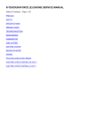
Flow Orientation:
Turn Lever
In Direction
Pressure
From Port
For CW (Right Hand) Rotation
For CCW (Left Hand) Rotation
X
P
YS
X
S
YP
Adjustment Procedure:
1
Loosen the flow-stop lock nut with 13mm wrench.
2
Turn the cam lever in the appropriate direction.
Turn the adjustment stud IN to decrease the flow
3
or OUT to increase the flow using the 4mm Allen
wrench.
When desired flow is acquired, hold the adjustment stud
stationary with the 4mm Allen wrench and tighten the
lock nut with the 13mm wrench (the proper torque for the
lock nut is 14 N-m [10 ft-lb]).
38
EATON Duraforce HPV Service Manual E-PUPI-TS020-E July 2012
Regulation Begin Adjustment for
HPV Pump with Hydraulic Remote
Control
Set Up
Tools / Equipment Required
• 0-600 psi np-gauge (optional:
two(2) 0-600 psi pressure
gauges or transducers)
• 0-6000 psi pressure gauge
or transducer
• 13mm offset
closed-end wrench
• Hammer and punch
Important
AFTER adjusting the
regulation begin, you must
reset the pump maximum
displacement setting. Follow
the instructions on pages
7-8 to reset the pump
maximum displacement.
WARNING
If performing this procedure
on a vehicle, care must
be taken. The pump will
be put on stroke during
this procedure, hence the
vehicle must be safely
elevated to allow the
function to free-wheel. If
this is NOT possible, then
the pump workports "P" and
"S" must be short circuited
to each other to avoid
movement of the function.
EATON Duraforce HPV Service Manual E-PUPI-TS020-E July 2012
39
Regulation Begin Adjustment for HPV
Pump with Hydraulic
Remote Control
Procedure for Right-Hand (CW) Rotation
Note
Prior to performing this
procedure, verify that the
hydraulic neutral on the pump
is correctly adjusted. Use the
instructions on page 3 to check
and adjust the hydraulic neutral
setting if required.
Adjustment Procedure
for Right-Hand Rotation
(CW) Pump:
1. Install the 0-600 psi np-gauge into ports "Y" and "Z" ("HI" side into "Y" and "LO" side
into "Z").
2. Install the 0-6000 psi gauge into gauge port "Mp".
3. Set the input speed to Operational Speed.
4. While simultaneously monitoring both gauges, slowly supply control pressure into
port "Y". Note the pressure on the np-gauge when you first see pressure at port
"Mp". This is the regulation begin pressure for workport "P".
5. To Adjust the Regulation Begin Pressure:
a. Use the hammer and punch to loosen (rotate CCW) "Spanner Nut #2".
b. U
se the 13mm wrench on "Locking Nut #2" to adjust "Regulation Begin Cup #2".
Turn it IN to increase the regulation begin pressure or turn it OUT to decrease it.
c. Use the hammer and punch to tighten (rotate CW) "Spanner Nut #2".
d. Repeat steps #3 and #4 to verify that the regulation begin pressure is correct.
6. Install the 0-600 psi np-gauge into ports "Z" and "Y" ("HI" side into "Z" and "LO" side
into "Y").
7. Install the 0-6000 psi gauge into gauge port "Ms".
8. Set the input speed to operational speed.
9. While simultaneously monitoring both gauges, slowly supply control pressure into
port "Z". Note the pressure on the np-gauge when you first see pressure at port
"Ms". This is the regulation begin pressure for workport "S".
10. To Adjust the Regulation Begin Pressure:
a. Use the hammer and punch to loosen (rotate CCW) "Spanner Nut #1".
b. U
se the 13mm wrench on "Locking Nut #1" to adjust "Regulation Begin Cup #1".
Turn it IN to increase the regulation begin pressure or turn it OUT to decrease it.
c. Use the hammer and punch to tighten (rotate CW) "Spanner Nut #1".
d. Repeat steps #8 and #9 to verify that the regulation begin pressure is correct.
11. Follow all steps on pages 7-8 to reset the maximum displacement.
40
EATON Duraforce HPV Service Manual E-PUPI-TS020-E July 2012
Regulation Begin Adjustment for HPV
Pump with Hydraulic
Remote Control
Procedure for Left-Hand Rotation (CCW) Pump
Note
Prior to performing this
procedure, verify that the
hydraulic neutral on the pump
is correctly adjusted. Use the
instructions on page 3 to check
and adjust the hydraulic neutral
setting if required.
Adjustment Procedure
for Left-Hand Rotation
(CCW) Pump:
1. Install the 0-600 psi np-gauge into ports "Y" and "Z" ("HI" side into "Y" and "LO" side
into "Z").
2. Install the 0-6000 psi gauge into gauge port "Ms".
3. Set the input speed to operational speed.
4. While simultaneously monitoring both gauges, slowly supply control pressure into
port "Y". Note the pressure on the np-gauge when you first see pressure at port
"Ms". This is the regulation begin pressure for workport "S".
5. To Adjust the Regulation Begin Pressure:
a. Use the hammer and punch to loosen (rotate CCW) "Spanner Nut #2".
b. U
se the 13mm wrench on "Locking Nut #2" to adjust "Regulation Begin Cup #2".
Turn it IN to increase the regulation begin pressure or turn it OUT to decrease it.
c. Use the hammer and punch to tighten (rotate CW) "Spanner Nut #2".
d. Repeat steps #3 and #4 to verify that the regulation begin pressure is correct.
6. Install the 0-600 psi np-gauge into ports "Z" and "Y" ("HI" side into "Z" and "LO" side
into "Y").
7. Install the 0-6000 psi gauge into gauge port "Mp".
8. Set the input speed to operational speed.
9. While simultaneously monitoring both gauges, slowly supply control pressure into
port "Z". Note the pressure on the np-gauge when you first see pressure at port
"Mp". This is the regulation begin pressure for workport "P".
10. To Adjust the Regulation Begin Pressure:
a. Use the hammer and punch to loosen (rotate CCW) "Spanner Nut #1".
b. U
se the 13mm wrench on "Locking Nut #1" to adjust "Regulation Begin Cup #1".
Turn it IN to increase the regulation begin pressure or turn it OUT to decrease it.
c. Use the hammer and punch to tighten (rotate CW) "Spanner Nut #1".
d. Repeat steps #8 and #9 to verify that the regulation begin pressure is correct.
11. Follow all steps on pages 7-8 to reset the maximum displacement.
EATON Duraforce HPV Service Manual E-PUPI-TS020-E July 2012
41
Regulation Begin Adjustment for
HPV Pumps with "M2P" (MechanicalHydraulic with POR) Controls
Set Up
Tools / Equipment Required
• 0-600 psi np-gauge (optional:
two(2) 0-600 psi pressure
gauges or transducers)
• 0-6000 psi pressure gauge
or transducer
• 24mm wrench
• torque wrench capable of
setting 150 N-m (111 ft-lb)
• regulation begin shims (refer
to the Eaton spare parts
catalog for part numbers)
Note: for shim set #2: 0.1mm
shim change = 0.38° change in
lever movement
WARNING
If performing this procedure
on a vehicle, care must
be taken. The pump will
be put on stroke during
this procedure, hence the
vehicle must be safely
elevated to allow the
function to free-wheel. If
this is not possible, then
the pump workports "P" and
"S" must be short circuited
to each other to avoid
movement of the function.
42
EATON Duraforce HPV Service Manual E-PUPI-TS020-E July 2012
Note
This Service Bulletin is ONLY
valid for HPV pumps with
"M2P" (Mechanical-Hydraulic
with POR) controls.
Regulation Begin Adjustment for
HPV Pumps with "M2P" (MechanicalHydraulic with POR) Controls
Procedure for Right-Hand (CW) Rotation
Note
Prior to performing this
procedure, verify that the
hydraulic neutral on the pump
is correctly adjusted. Use the
instructions on page 3 to check
and adjust the hydraulic neutral
setting if required.
Adjustment Procedure for
Right-Hand (CW) Rotation
Pumps:
1. Install the 0-600 psi np-gauge into port "Y" and "Z" ("HI" side into "Y" and "LO" side
into "Z").
2. Install the 0-6000 psi gauge into port "Mp".
3. Set the input speed to operational speed.
4. While simultaneously monitoring both gauges, slowly turn the cam lever CCW (as
illustrated on page 42). Record the pressure on the np-gauge when you first see
pressure at port "Mp". This is the regulation begin pressure for workport "P".
5. To adjust the regulation begin pressure:
a. Remove End Plug #2 with the 24mm wrench.
b. Add shims to Shim Set #2 to INCREASE the regulation begin setting, or remove
shims to DECREASE the regulation begin setting.
Note: You may need to add or remove shims to or from Shim Set #1 if you cannot
acquire the desired regulation begin pressure by changing shims from Shim Set #2.
c. Reinstall End Plug #2 and torque it to 150 N-m (111 ft-lb).
6. Repeat steps #4 and #5 until the desired regulation begin pressure is acquired.
7. Install the 0-600 psi np-gauge into ports "Z" and "Y" ("HI" side into "Z" and "LO" side
into "Y").
8. Install the 0-6000 psi gauge into port "Ms".
9. Set the input speed to operational speed.
10. While simultaneously monitoring both gauges, slowly turn the cam lever CW (as
illustrated on page 42). Record the pressure on the np-gauge when you first see
pressure at port "Ms". This is the regulation begin pressure for workport "S".
11. To adjust the regulation begin pressure:
a. Remove End Plug #1 with the 24mm wrench.
b. Add shims to Shim Set #2 to INCREASE the regulation begin setting, or remove
shims to DECREASE the regulation begin setting.
Note: You may need to add or remove shims to or from Shim Set #1 if you cannot
acquire the desired regulation begin pressure by changing shims from Shim Set #2.
c. Reinstall End Plug #1 and torque it to 150 N-m (111 ft-lb).
12. Repeat steps #10 and #11 until the desired regulation begin pressure is acquired.
EATON Duraforce HPV Service Manual E-PUPI-TS020-E July 2012
43
Regulation Begin Adjustment for
HPV Pump with M2P (MechanicalHydraulic with POR) Controls
Procedure for Left-Hand (CCW) Rotation
Note
Prior to performing this
procedure, verify that the
hydraulic neutral on the pump
is correctly adjusted. Use the
instructions on page 3 to check
and adjust the hydraulic neutral
setting if required.
Adjustment Procedure
for Left-Hand (CCW)
Rotation Pumps:
1. Install the 0-600 psi np-gauge into ports "Y" and "Z" ("HI" side into "Y" and "LO" side
into "Z").
2. Install the 0-6000 psi gauge into port "Ms".
3. Set the input speed to operational speed.
4. While simultaneously monitoring both gauges, slowly turn the cam lever CCW (as
illustrated on page 42). Record the pressure on the np-gauge when you first see
pressure at port "Ms". This is the regulation begin pressure for workport "S".
5. To adjust the regulation begin pressure:
a. Remove End Plug #2 with the 24mm wrench.
b. Add shims to Shim Set #2 to INCREASE the regulation begin setting, or remove
shims to DECREASE the regulation begin setting.
Note: You may need to add or remove shims to or from Shim Set #1 if you cannot
acquire the desired regulation begin pressure by changing shims from Shim Set #2.
c. Reinstall End Plug #2 and torque it to 150 N-m (111 ft-lb).
6. Repeat steps #4 and #5 until the desired regulation begin pressure is acquired
7. Install the 0-600 psi np-gauge into ports "Z" and "Y" ("HI" side into "Z" and "LO" side
into "Y").
8. Install the 0-6000 psi gauge into port "Mp".
9. Set the input speed to operational speed.
10. While simultaneously monitoring both gauges, slowly turn the cam lever CW (as
illustrated on page 42). Record the pressure on the np-gauge when you first see
pressure at port "Mp". This is the regulation begin pressure for workport "P".
11. To adjust the regulation begin pressure:
a. Remove End Plug #1 with the 24mm wrench.
b. Add shims to Shim Set #2 to INCREASE the regulation begin setting, or remove
shims to DECREASE the regulation begin setting.
Note: You may need to add or remove shims to or from Shim Set #1 if you cannot
acquire the desired regulation begin pressure by changing shims from Shim Set #2.
c. Reinstall End Plug #1 and torque it to 150 N-m (111 ft-lb).
12. Repeat steps #10 and #11 until the desired regulation begin pressure is acquired.
44
EATON Duraforce HPV Service Manual E-PUPI-TS020-E July 2012
Cold Start Valve Adjustment for
HPV Pump with CA Control
Important
This procedure is intended for
field adjustments only.
Set Up and Procedure
Tools / Equipment Required
• 0-600psi Pressure Gauge.
• 10mm wrench (X2)
Adjusting the
Cold Start Valve
Important
Vehicle’s drive system must be kept in Neutral throughout this procedure. In order to insure this
condition, it is recommended to disconnect both My and Mz solenoid connections.
This test must be performed with the oil at operating temperature.
1. Install the 0-600psi Gauge on test port “Mt” of the pump’s filter block.
2. While monitoring the pressure on the “Mt” port.
a. Increase the Engine RPM from the low idle all the way to max RPM.
b. The pressure value at port “Mt” during max RPM is the Cold Start Valve setting.
Contact Eaton Engineering for the correct value for your pump.
DANGER
In order to prevent damages to the filter element,
this value must be kept lower than 580psi
3. To adjust the Cold Start Valve setting:
a. Loosen the lock nut while holding the adjustment stud in place
b. Turn the adjustment in to increase the Cold Start Valve setting.
c. Turn the adjustment out to decrease the Cold Start Valve setting.
d. Tighten the lock nut while holding the adjustment stud in place.
EATON Duraforce HPV Service Manual E-PUPI-TS020-E July 2012
45
D3.1 Variable Orifice Adjustment
for HPV with CA Control
(Regulation Begin Setting)
Important
This procedure is intended for
field adjustments only.
Set Up and Procedure
Tools / Equipment Required
• Engine RPM Tachometer.
• 13mm wrench
• 4mm Allen key
Adjusting D3.1
Variable Orifice:
Important
Eaton recommends that the vehicle be lifted off the ground throughout this procedure.
This test must be performed with the oil at operating temperature.
DANGER
The HPVCA pump will be put on stroke during this procedure; as a result, the vehicle’s propel
motor(s) will be turning while measurements / adjustments are taking place.
1. While monitoring the Engine RPM, slowly increase the Engine RPM until the
vehicle’s propel motor(s) start to rotate.
2. Record the Engine RPM at which the propel motor(s) started their rotation. This
RPM Value is the pump’s regulation begin RPM and must match the value specified
for the vehicle. Contact Eaton Engineering for this value
3. To adjust the D3.1 variable orifice setting:
46
a. Loosen the lock nut while holding the adjustment stud in place
b. Turn the adjustment in to decrease the Regulation Begin RPM Setting.
c. Turn the adjustment out to increase the Regulation Begin RPM Setting.
d. Tighten the lock nut while holding the adjustment stud in place.
EATON Duraforce HPV Service Manual E-PUPI-TS020-E July 2012
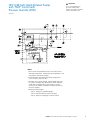
Power Limiter Valve Adjustment
for HPV Pump with CA Control
Important
This procedure is intended for
field adjustments only.
Set Up and Procedure
Tools / Equipment Required
• 0-600psi Differential
Pressure Gauge.
• 11mm wrench
• 10mm Wrench
• 3mm Allen Key
Adjusting the Power
Limiter Valve
Important
Vehicle’s drive system must be kept in Neutral throughout this procedure. In order to insure this
condition, it is recommended to disconnect both My and Mz solenoid connections.
This test must be performed with the oil at operating temperature.
1. Install the 0-600psi Differential Gauge as follows:
a. Connect the HI side to the “ML” port
b. Connect the LO side to the “Msp” port.
2. While monitoring the pressure on the Differential Gauge:
a. Increase the Engine RPM from the low idle all the way to max RPM.
b. The pressure value on the Differential Gauge during max RPM is the Power
Limiter Valve setting. Contact Eaton Engineering for this value.
3. To adjust the Power Limiter Valve setting:
a Loosen the lock nut while holding the adjustment stud in place
bC
rack open the upper part of the power limiter valve body while holding the
adjustment stud in place.
DANGER
Do not move this portion of the valve body more than 1/8 of a turn.
Excessive movement can result in disassembly of the valve.
c. While holding the Valve body in place, turn the adjustment in to increase the
Power Limiter Valve setting, or out to decrease it.
d. Tighten the upper part of the Power Limiter valve while holding the adjustment
stud in place.
e. Tighten the lock nut while holding the adjustment stud in place.
EATON Duraforce HPV Service Manual E-PUPI-TS020-E July 2012
47
Switching Valve Adjustment for
HPV Pump with CA Control
Important
This procedure is intended for
field adjustments only.
Set Up and Procedure
Tools / Equipment Required
• 0-600psi Pressure Gauge.
• Engine RPM Tachometer.
• 13mm wrench
• 4mm Allen key
Adjusting the
Switching Valve
Important
Eaton recommends that the vehicle be lifted off the ground throughout this procedure.
This test must be performed with the oil at operating temperature.
DANGER
The HPVCA pump will be put on stroke during this procedure; as a result, the vehicle’s propel
motor(s) will be turning while measurements / adjustments are taking place.
1. Install the 0-600psi Gauge on test port “Y” of the pump control.
2. With the vehicle lifted off the ground, Energize solenoid Mz.
3. While monitoring the Engine RPM and the pressure in port “Y”:
a. Slowly increase the Engine RPM from low idle.
b. The pressure in port “Y” will increase as the Engine RPM increases, then will
suddenly drop back to charge pressure.
c. R
ecord the Engine RPM when the pressure in port “Y” suddenly drops back to
charge pressure.
4. This Engine RPM value must be equal to the mid point between “Engine low idle RPM”
and “Pump’s Regulation Begin Engine RPM” ± 20RPM (see page 46).
5. To adjust the Switching Valve Setting:
48
a. Loosen the lock nut while holding the adjustment stud in place
b. Turn the adjustment in to increase the Switching Valve value.
c. Turn the adjustment out to decrease the Switching Valve value.
d. Tighten the lock nut while holding the adjustment stud in place.
EATON Duraforce HPV Service Manual E-PUPI-TS020-E July 2012
Additional Information
Environmental Concerns
Important
Protection of the natural fundamentals of life is one of our
predominant tasks. We are continuously improving the
protection of the environment as far as applications are
concerned. We encourage you to contribute your share to
comply with this demand. In connection with work to be
performed, the environmental regulations of the machine
manufacturer must be respected.
You have been provided information on the conversion of
DuraForce products. Proper application of the information
requires specific training and may require use of specialized
tooling and equipment. All requests for training must be
coordinated through your Eaton Account Manager. He can
also provide you price and availability of any specialized
tooling. If you choose to proceed with the conversion of the
DuraForce products absent the necessary training and/or
these specialized tools, you do so at your risk.
In general:
• Greases and oils which cannot be used any more have to
be collected. They are normally a threat to water reserves
and must be kept away from the environment.
• Adhere to national and local regulations for waste disposal.
Eaton will accept no claim for warranty resulting from
deficiencies in the conversion. Please refer to the
Eaton literature web site for warranty information at
www.eaton.com/hydraulics/warranty.
EATON Duraforce HPV Service Manual E-PUPI-TS020-E July 2012
49
50
EATON Duraforce HPV Service Manual E-PUPI-TS020-E July 2012
EATON Duraforce HPV Service Manual E-PUPI-TS020-E July 2012
51
Eaton
Hydraulics Group USA
14615 Lone Oak Road
Eden Prairie, MN 55344
USA
Tel: 952-937-9800
Fax: 952-294-7722
www.eaton.com/hydraulics
© 2012 Eaton Corporation
All Rights Reserved
Printed in USA
Document No. E-PUPI-TS020-E
July 2012
Eaton
Hydraulics Group Europe
Route de la Longeraie 7
1110 Morges
Switzerland
Tel: +41 (0) 21 811 4600
Fax: +41 (0) 21 811 4601
Eaton
Hydraulics Group Asia Pacific
Eaton Building
No.7 Lane 280 Linhong Road
Changning District, Shanghai
200335 China
Tel: (+86 21) 5200 0099
Fax: (+86 21) 2230 7240