1
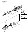
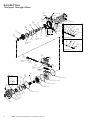
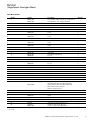
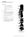
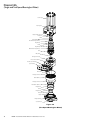
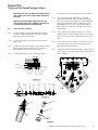
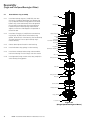
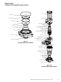
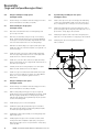
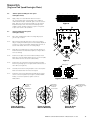
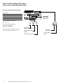
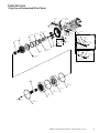
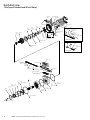
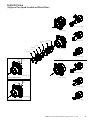
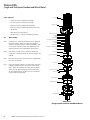
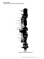
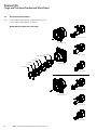
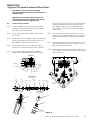
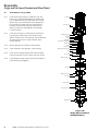
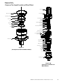
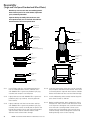
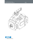
Char-Lynn®
HP30 Motors
Design code - 002
Parts and repair
information
Table of contents
Bearingless motors
Section
Description
1.0
Exploded View
2.0
Part List
3.0Disassembly
4.0Reassembly
5.0
How to Order Replacement Parts
Page No.
3-4
5-8
9-10
11-15
16
Standard and wheel motor
6.0
Exploded View 17-19
7.0
Part List
20-23
8.0Disassembly
24-26
9.0Reassembly
27-33
10.0
How to Order Replacement Parts
34
2
EATON HP-30 MOTOR SERVICE MANUAL E-MOGG-RR001-E June 2015
Exploded View
(Single Speed - Bearingless Motor)
Housing,
Valve
1
7 Plug
SubAssembly
Nameplate
98
6
Plug
Sub-Assembly
Ring,
Backup
16
Drive,
Valve
20
Ring,
Backup
16
Ring,
Backup
13
Cap Screw, 12 Pt
34
O-ring
12
10 Plug
Sub-Assembly
9
Seat, Ball Sub-Assy
36
Poppet
38
Spring
Valve
19
For Relief
Valve Option
18
Pin,
Dowel
15
O-ring
8 Ball, Steel
Sleeve,
Dash Pot
5
Spring
4
Poppet
Piston, Shuttle
3
2
Poppet
3
Spring
4
Sleeve,
Dash Pot
5
39
Plug S/A
11
Spring,
Compression
Plug
Sub-Assembly
6
For Closed Loop Design
14
Inner Balance Ring
Sub-Assy
Spring
4
Ball
47
Spring
4
17
Outer Balance Ring
Sub-Assy
Plug
Sub-Assembly
6
For Open Loop Design
For Open Loop
Design
Plug,
Orifice
48
33
Drive
O-ring
(Section Seal)
21
49
Strainer
Plate, Valve
22
Geroler
Sub-Assy
32
O-ring
(Section Seal)
21
O-ring
(Section Seal)
21
Flange,
Mounting
35
Seal, Shaft face
40
EATON HP-30 MOTOR SERVICE MANUAL E-MOGG-RR001-E June 2015
3
Exploded View
(Two Speed - Bearingless Motor)
7
Plug Sub-Assembly
Housing,
Valve
1
6
Plug
Sub-Assembly
Ring,
Backup
13
Ring,
Backup
16
Nameplate
98
34
Cap Screw,
12 Pt
O-ring
12
Ring,
Backup
16
10 Plug
Sub-Assembly
9 Seat,
Ball Sub-Assy
Poppet 36
Spring 38
Valve
19
8 Ball, Steel
For Relief
Valve Option
18
Pin,
Dowel
Drive,
Valve
20
39 Plug S/A
11
Spring,
Compression
14
Inner Balance Ring
Sub-Assy
15
O-ring
Sleeve,
Dash Pot
5
Spring
4
Poppet
3
Piston, Shuttle
2 Poppet
Sleeve,
3 Spring
Dash Pot
4
5
Plug
Sub-Assembly
6
For Closed Loop Design
Spring
4
17
Outer Balance Ring
Sub-Assy
Ball
54
For Open Loop Design
Plug,
Sub-Assy
30
Plug,
Sub-Assy
28
27
Spring,
Compression
26
Spring,
Compression
25
Spool,
Control
24
Housing,
Spool
For Open Loop
Design
Plug,
Orifice
55
Ring,
Backup
47
56
Strainer
Plate,
Balance
Sub-Assy
52
29
Plug,
Sub-Assy
23
Gasket,
Spool Housing
Drive
33
21
O-ring (Section Seal)
22
Plate, Selector Sub-Assy
O-ring
48
21
O-ring (Section Seal)
Plug,
Sub-Assy
53
32
Geroler Sub-Assy
O-ring
49
40
Seal,
Shaft face
4
31
Screw,
Cap
35
Flange,
Mounting
Ring,
Backup
50
21
O-ring (Section Seal)
Spring®
51
EATON HP-30 MOTOR SERVICE MANUAL E-MOGG-RR001-E June 2015
Spring
4
Plug
Sub-Assembly
6
Part List
(Single Speed - Bearingless Motor)
Item Description
Ref No.
Part No.
1
5998727-001 5998727-007
2
201494-002
3
8567-000
4
230079-000
5
112126-001
6
9266-006
X
250003-904
7
9266-006
X
250003-904
8
18026-000
9
5992342-001
X
250003-902
10
9266-006
X
250003-904
11
6203-000
X 12
14502-032
X
13
5989483-001
14
5991782-001
268009-005
X 15
14502-040
X
16
5989483-002
17
5991783-001
268009-005
18
5987800-001
19
5987445-001
20
5987844-001
X
21
250002-161
22
5989335-001
32
*
33
*
34
*
35
5987755-007
5987755-009
36
113538-001
38
113186-001
39
9072-006
X
250003-905
X
40 9080-001
47
285020-140
48
9289-001
49
31500-452
9900847-000
Description
Quantity
Housing, Valve 1.0625-12 UN-2B SAE O-Ring Ports (2)
1
Housing, Valve G 1 BSP Straight Thread Ports
1
Piston, Shuttle
1
Poppet
2
Spring
2
Sleeve, Dash Pot
2
Plug Sub-Assembly
2
O-ring
2
Plug Sub-Assembly
1
O-ring
1
Ball, Steel
1
Seat, Ball Sub-Assy
1
O-ring
1
Plug Sub-Assembly
1
O-ring
1
Spring, Compression
10
O-ring
1
Ring, Backup
1
Inner Balance Ring Sub-Assy
1
Pin, Roll
2
O-ring
1
Ring, Backup
2
Outer Balance Ring Sub-Assy
1
Pin, Roll
2
Pin, Dowel
1
Valve
1
Drive, Valve
1
O-ring (Section Seal)
3
Plate,Valve
1
Geroler Sub-Assy
1
Drive, Main
1
Cap Screw, 12 PT
9
Flange, Mounting Shuttle Valve With .5625-18 UNF-2B 1
SAE O-Ring Case Drain Port In Mounting Flange .
Flange, Mounting Check Valve With Orifice Plug, 1
5625-18 UNF-2B SAE O-Ring Case
Drain Port In Valve Housing
Poppet (for relief valve unit only)
1
Spring (for relief valve unit only)
1
Plug Sub-Assembly
1
O-ring
Seal, Shaft Face
1
Ball (for open loop design only)
2
Plug, Orifice (for open loop design only)
1
Strainer (for open loop design only)
Seal Kit - Contains Parts Indicated by X
1
* = See Chart
EATON HP-30 MOTOR SERVICE MANUAL E-MOGG-RR001-E June 2015
5
Part List
(Single Speed - Bearingless Motor)
Displacement
Ref. No. 32
Width
Ref. No. 33
Length
Ref. No. 34
Length
cm3 /r [in3/r]
Geroler
mm [inch]
Drive
mm [inch]
Cap Screw
mm [inch]
343.8 [20.98]
400.0 [24.40]
434.2 [26.50]
479.5 [29.26]
677.3 [41.33]
5991701-001
5991701-002
5991701-006
5991701-003
5991701-007
32,1 [1.26]
37,3 [1.47]
40,6 [1.60]
44,7 [1.76]
63,2 [2.49]
5992182-001
5992182-002
5992182-006
5992182-003
5992182-008
130,4 [5.13]
135,7 [5.34]
138,9 [5.47]
143,1 [5.63]
161,2 [6.35]
114154-025
114154-026
114154-026
114154-027
114154-029
185,2 [7.29]
190,5 [7.50]
190,5 [7.50]
197,9 [7.79]
216,4 [8.52]
6
EATON HP-30 MOTOR SERVICE MANUAL E-MOGG-RR001-E June 2015
Part List
(Two Speed - Bearingless Motor)
Item description
Ref No.
Part No.
1
5998727-001 5998727-007
2
201494-002
3
8567-000
4
230079-000
5
112126-001
6
9266-006
X
250003-904
7
9266-006
X
250003-904
8
18026-000
9
5992342-001
X
250003-902
10
9266-006
X
250003-904
11
6203-000
X12
14502-032
X
13
5989483-001
14
5991782-001
268009-005
X15
14502-040
X
16
5989483-002
17
5991783-001
268009-005
18
5987800-001
19
5987445-001
20
5987844-001
X
21
250002-161
22
5991781-001
5989384-001
X
23
5990046-001
24
5989326-002
25
112850-002
26
112211-001
27
114587-001
28
9151-002
X
250003-908
29
9072-006
250003-908
X
30
9266-003
X
250003-904
31
16148-320
32
*
33
*
34
*
Description
Quantity
Housing, Valve 1.0625-12 UN-2B SAE O-Ring Ports (2)
Housing, Valve G 1 BSP Straight Thread Ports (2)
Piston, Shuttle
Poppet
Spring
Sleeve, Dash Pot
Plug Sub-Assembly
O-ring
Plug Sub-Assembly
O-ring
Ball, Steel
Seat, Ball Sub-Assy
O-ring
Plug Sub-Assembly
O-ring
Spring, Compression
O-ring
Ring, Backup
Inner Balance Ring Sub-Assy
Pin, Roll
O-ring
Ring, Backup
Outer Balance Ring Sub-Assy
Pin, Roll
Pin, Dowel
Valve
Drive, Valve
O-ring (Section Seal)
Plate, Selector Sub-Assy
Insert, Sleeve
Gasket, Spool Housing
Housing, Spool
Spool, Control
Spring, Compression
Spring, Compression
Plug Sub-Assembly
O-ring
Plug Sub-Assembly
O-ring
Plug Sub-Assembly
O-ring
Screw, Cap
Geroler Sub-Assy
Drive, Main
Cap Screw, 12 PT
1
1
1
2
2
2
2
2
1
1
1
1
1
1
1
10
1
1
1
2
1
2
1
2
1
1
1
3
1
1
1
1
1
1
1
1
1
1
1
1
1
10
1
1
9
EATON HP-30 MOTOR SERVICE MANUAL E-MOGG-RR001-E June 2015
7
Part List
(Two Speed - Bearingless Motor)
Item description
Ref No.
Part No.
Description
Quantity
35
5991797-005
Flange, Mounting Shuttle Valve With .5625-18 UNF-2B SAE O-Ring Case Drain Port
5987755-010
Flange, Mounting Shuttle Valve With .5625-18 UNF-2B SAE O-Ring Case Drain Port In Mounting Flange .
36
113538-001
Poppet (for relief valve unit only)
38
113186-001
Spring (for relief valve unit only)
39
9072-006
Plug Sub-Assembly
X
250003-905
O-ring
X
40 9080-001
Seal, Shaft Face
X
47
5989483-004
Ring, Backup
X
48
112530-044
O-ring
X
49
112530-139
O-ring
X
50
14649-003
Ring, Backup
51
6023120-001Spring
52
6023947-001 Plate, Balance Sub-Assy 53
9266-006
Plug Sub-Assembly
X
250003-904
O-ring
54
285020-140
Ball (for open loop design only)
X
55
9289-001
Plug, Orifice (for open loop design only)
X
56
31500-452
Strainer (for open loop design only) 9900682-000
Seal Kit Contains Parts Indicated by X
1
1
1
1
1
1
1
1
1
1
1
1
1
1
1
2
1
1
* = See Chart
Displacement
Ref. No. 32
Width
Ref. No. 33
Length
Ref. No. 34
Length
cm /r [in3/r]
Geroler
mm [inch]
Drive
mm [inch]
Cap Screw
mm [inch]
343.8 [20.98]
400.0 [24.40]
434.2 [26.50]
479.5 [29.26]
677.3 [41.33]
5991701-001
5991701-002
5991701-006
5991701-003
5991701-007
32,1 [1.26]
37,3 [1.47]
40,6 [1.60]
44,7 [1.76]
63,2 [2.49]
5992182-001
5992182-002
5992182-006
5992182-003
5992182-008
130,4 [5.13]
135,7 [5.34]
138,9 [5.47]
143,1 [5.63]
161,2 [6.35]
114154-025
114154-026
114154-026
114154-027
114154-029
185,2 [7.29]
190,5 [7.50]
190,5 [7.50]
197,9 [7.79]
216,4 [8.52]
3 8
EATON HP-30 MOTOR SERVICE MANUAL E-MOGG-RR001-E June 2015
Disassembly
(Single and Two speed Bearingless Motor)
Tools required
•
7/32 inch Hex Key (Relief Valve Plug)
•
1/4 inch Hex Key (Shuttle Valve Plug)
•
5/16 inch Hex Key (Spool Housing Plug)
•
5/32 inch Hex Key (Spool Housing Screw, Cap)
•
7/8 Socket
•
9/16 Socket (12 Point Drive)
•
Torque wrench - 142 Nm [1260 lb-in] capacity
3.0Disassembly
3.0.1
3.0.2
3.0.3
3.0.4
Cleanliness is extremely important when repairing
hydraulic motors. Work in a clean area. Before
disconnecting the hydraulic motor thoroughly clean
the exterior. Remove motor from application and
drain the oil from the motor before disassembly.
Remove the 9 cap screws and disassemble the
motor in the vertical position as shown in
Figure 1A & 1B.
Remove shuttle valve (and relief valve if applicable)
from Valve Housing.
Check all mating surfaces. To reduce the chance of
leakage, replace any parts that have scratches or
burrs. Wash all metal parts in clean solvent. Blow
them dry with pressurized air. Do not wipe parts
dry with paper towels or cloth as lint in a hydraulic
system will cause damage.
Screws, Cap
Housing, Valve
Spring, Compression
Pin, Dowel
O-ring
Ring, Backup
Inner Balance Ring Sub-Assy
Ring, Back-up
O-ring
Ring, Back-up
Outer Balance Ring Sub-Assy
Valve
Drive, Valve
O-ring (Section Seal)
Plate, Valve
O-ring (Section Seal)
Drive, Main
Geroler Sub-Assy
O-ring (Section Seal)
Flange, Mounting
Seal, Shaft Seal
Figure 1A
(Single Bearingless Motor)
EATON HP-30 MOTOR SERVICE MANUAL E-MOGG-RR001-E June 2015
9
Disassembly
(Single and Two Speed Bearingless Motor)
Screws, Cap
Housing, Valve
Spring, Compression
Pin, Dowel
O-ring
Ring, Backup
Inner Balance Ring Sub-Assy
Ring, Back-up
O-ring
Ring, Back-up
Outer Balance Ring Sub-Assy
Valve
Drive, Valve
O-ring (Section Seal)
Plate, Selector Sub-Assy
Gasket, Spool Housing
Spool Housing
Drive, Main
O-ring (Section Seal)
Geroler Sub-Assy
O-ring (Section Seal)
Plate Balance Sub-Assy
Ring, Backup
O-ring
Ring, Backup
O-ring
Spring
Flange, Mounting
Seal, Shaft Seal
Figure 1B
(Two Speed Bearingless Motor)
10
EATON HP-30 MOTOR SERVICE MANUAL E-MOGG-RR001-E June 2015
Reassembly
(Single and Two Speed Bearingless Motor)
Note: Always use new seals when reassembling hydraulic
motors. Refer to parts list for seal kit number and replacement parts.
Important: During reassembly, lubricate the new seals
with a petroleum jelly such as Vaseline®. Also lubricate
machined surfaces with clean hydraulic fluid.
4.0
Valve housing assembly
4.0.1
Install one poppet, spring, dash pot and threaded
internal hex plug with O-ring into shuttle valve bore
from one end of Valve Housing.
4.0.2
Install shuttle piston from opposite end of shuttle
valve cavity.
4.0.3
Install one shuttle valve poppet, spring, dash pot onto
piston and threaded internal hex plug with O-ring
from opposite end of shuttle valve cavity.
4.0.4
preservative. Torque both plugs to 360 +/- 36 lbf-in.
4.0.5. For a motor with open loop design, Install Ball,
Spring and threaded internal hex plug with O-ring
form one end of cavity. And then install another Ball,
Spring and threaded internal hex plug with O-ring
from opposite end of cavity. Torque both plugs to
360 +/- 36 lbf-in. Plugs may have light coat of oil or
preservative.
4.0.6. For a motor with low pressure relief valve, install
poppet, spring and plug. Plug threads may have light
coat of oil or preservative. Torque plug to 180+/-18
lb-in.
Shuttle plug threads may have light coat of oil or
4.0.7. For a motor without low-pressure relief valve, Install
and torque plug to 180 ± 18 lbf-in. Plug may have
light coat of oil or preservative.
4.0.8. Install ball and seat ball sub-assembly. Torque seat to
60 +/- 6 lbf-in. Install plug sub-assembly and torque to
360 +/- 36 lbf-in.
Shuttle Valve
Shuttle
Valve
Plug O-ring
Sleeve,
Dash Pot
Sleeve, Dash Pot
Spring
Spring
Poppet
Poppet
Piston, Shuttle
Shuttle Valve Parts
(Shown Enlarged)
Plug
O-ring
Sleeve,
Dash Pot
Spring
Poppet
Relief Valve
Piston,
Shuttle
Poppet
Spring
Sleeve,
Dash Pot
Relief
Valve
Relief Valve Parts
(Shown Enlarged)
Poppet
Poppet
Spring
Spring
Plug
O-ring
Plug
O-ring
Figure 2
EATON HP-30 MOTOR SERVICE MANUAL E-MOGG-RR001-E June 2015
11
Reassembly
(Single and Two Speed Bearingless Motor)
4.1
Outer balance ring assembly
4.1.1
Install one backup ring (75,1 [2.96] OD), then one
O-ring (72,7 [2.86] ID) followed by one backup ring
(75,1 [2.96] OD) into the O-ring groove in the outer
balance ring. Seals and backups are to be greased.
Ensure splits in backup rings are mated correctly.
Location of splits in backup rings should not be
aligned, a minimum of 90 degrees of separation is
recommended.
4.1.2
4.1.3
Install one O-ring (47,3 [1.86] ID) then one backup
ring (48,6 [1.91] OD) into the inner balance ring
groove, located in the valve housing. Seal and backup
are to be greased. Ensure split in backup ring is
mated correctly.
Grease dowel pin and install in valve housing.
4.1.4
Install 10 balance ring springs in valve housing.
4.1.5
Install inner and outer balance ring sub-assemblies
into valve housing. Ensure O-rings seals are seated.
4.1.6
Install greased O-ring section seal (139,4 [5.49] ID) in
valve housing O-ring groove.
Screws, Cap
Housing, Valve
Spring, Compression
Pin, Dowel
O-ring
Ring, Backup
Inner Balance Ring Sub-Assy
Ring, Back-up
O-ring
Ring, Back-up
Outer Balance Ring Sub-Assy
Valve
Drive, Valve
O-ring (Section Seal)
Plate, Valve
O-ring (Section Seal)
Drive, Main
Geroler Sub-Assy
O-ring (Section Seal)
Flange, Mounting
Seal, Shaft Seal
Figure 3A
(Single Speed Bearingless Motor)
12
EATON HP-30 MOTOR SERVICE MANUAL E-MOGG-RR001-E June 2015
Reassembly
(Single and Two Speed Bearingless Motor)
Screws, Cap
O-ring (Section Seal)
Housing, Valve
Plate Balance Sub-Assy
Ring, Backup
Spring, Compression
Pin, Dowel
O-ring
Ring, Backup
Inner Balance Ring Sub-Assy
O-ring
Ring, Backup
O-ring
Ring, Back-up
O-ring
Spring
Ring, Back-up
Outer Balance Ring Sub-Assy
Valve
Flange, Mounting
Drive, Valve
Seal, Shaft Seal
Plate, Selector Sub-Assy
Gasket, Spool Housing
O-ring (Section Seal)
Spool Housing
Figure 4
(Two Speed Bearingless Motor)
Drive, Main
O-ring (Section Seal)
Geroler Sub-Assy
O-ring (Section Seal)
Plate Balance Sub-Assy
Ring, Backup
O-ring
Ring, Backup
O-ring
Spring
Flange, Mounting
Seal, Shaft Seal
Figure 3B
(Two Speed Bearingless Motor)
EATON HP-30 MOTOR SERVICE MANUAL E-MOGG-RR001-E June 2015
13
Reassembly
(Single and Two Speed Bearingless Motor)
4.2
Flange assembly (For single speed
bearingless motor)
4.5
Spool housing assembly (For two speed
bearingless motor)
4.2.1
Position flange on workbench with the O-ring grooves face
down and install face seal (54,1 [2.13] OD).
4.5.1
Install control spool into spool housing by first lubricating
control spool with DTE26. Install control spool into spool
bore, verifying that the control spool moves freely in bore.
4.3
Final assembly (For single speed
bearingless motor)
4.5.2
4.3.1
Place drive in build fixture. Place mounting flange (seal
grooves up) over drive.
Install nested springs and counter bored plug into end of
spool housing spool bore. Plug may have light coat of oil or
preservative. Torque plug to 46 +/-2 lbf-ft.
4.5.3
Install plug in opposite end of spool bore. Plug may have
light coat of oil or preservative. Torque plug to 46 +/-2 lbf-ft.
4.5.4
Install plug into spool housing port and torque to
192 +/- 19 lbf-in.
4.3.2
Place Geroler assembly (seal groove up) over mounting
flange. Install greased O-ring section seal (139,4 [5.49] ID)
in seal groove of Geroler assembly. Align shuttle flow hole
of Geroler with shuttle flow hole of mounting flange.
4.3.3
Mark drive teeth that align (See Figure A) with dykem pen.
Install valve drive into internal star spline (See Figure B or C
for motor timing).
4.3.4
Install valve plate onto Geroler sub-assembly (valve plate
valve slots up). Align shuttle flow hole of valve plate with
shuttle flow hole of Geroler sub-assembly.
4.3.5
Install valve onto valve drive and selector plate assembly.
Ensure long leakage groove is aligned with marked tooth on
valve drive (see Figure D).
4.3.6
Carefully invert valve housing and place onto valve plate.
Make sure that shuttle flow holes are aligned.
4.3.7
Install nine cap screws lubricated with DTE-26. Pre-torque
each in a crisscross pattern (see Figure 7) to 80+/-10 lb-ft.
Finally, in a crisscross pattern, tighten screws to
105+/-5 lb-ft.
4.4
Flange assembly (For two speed
bearingless motor)
4.4.1
Position flange on workbench with the O-ring grooves face
down and install face seal (54,1[2.13] OD).
4.4.2
With mounting flange O-ring grooves up (see Figure 4),
install O-ring section seal (139,4 [5.49] ID) into flange. Install
back-up ring (62,1 [2.45] OD) over O-ring (55,2 [2.18] ID)
with flat side up. Back-up ring and O-rings may be greased
to assist in retaining parts.
4.4.3
Install spring in groove in mounting flange.
4.4.4
Install back-up ring (99,7 [3.93] OD) in groves of balance
plate sub assembly and then install O-ring (95,0 [3.74] ID)
over back-up ring from tapered side.
4.4.5
Install balance plate sub assembly in mounting flange with
tapered side down.
4.4.6
Install plug at 41 degree from horizontal centerline while
viewing from drive end (balance plate port), see Figure 5.
Plug may have light coat of oil or preservative. Torque plug
to 46 +/-2 lbf-ft.
14
EATON HP-30 MOTOR SERVICE MANUAL E-MOGG-RR001-E June 2015
41°
Figure 5
Reassembly
(Single and Two Speed Bearingless Motor)
4.6
Selector plate assembly (For two speed
bearingless motor)
4.6.1
Apply 1 drop of Loctite 290 in all 10 screw holes in
the selector plate while ensuring that no air is trapped
underneath the droplet. Install the gasket onto the selector
plate. Place the spool housing assembly onto the gasket.
Install and torque each of the 10 screws starting in the
middle working outwards using the sequence in Figure 6.
Torque each screw to 70 +/- 8 lbf-in.
4.7
Final assembly (For two speed
bearingless motor)
4.7.1
Place drive in build fixture. Place mounting flange (seal
grooves up) over drive.
8
6
9
3
2
1
4
10
5
7
Figure 6
2
7
5
4
4.7.2
Place Geroler assembly (seal groove up) over mounting
flange. Install greased O-ring section seal (139,4 [5.49] ID) in
seal groove of Geroler assembly. Align shuttle flow hole of
Geroler with shuttle flow hole of mounting flange.
4.7.3
Mark drive teeth that align (See Figure A) with dykem pen.
Install valve drive into internal star spline (See Figure B or C
for motor timing).
8
1
3
9
4.7.4
4.7.5
Install selector plate onto Geroler sub-assembly (selector
plate valve slots up). Align shuttle flow hole of selector plate
with shuttle flow hole of Geroler sub-assembly.
6
Figure 7
Install valve onto valve drive and selector plate assembly.
Ensure long leakage groove is aligned with marked tooth on
valve drive (see Figure D).
4.7.6
Carefully invert valve housing and place onto selector plate.
Make sure that shuttle flow holes are aligned.
4.7.7
Install nine cap screws lubricated with DTE-26. Pre-torque
each in a crisscross pattern (see Figure 7) to 80+/-10 lb-ft.
Finally, in a crisscross pattern, tighten screws to
105+/-5 lb-ft.
Mark two teeth that
align
Figure A (Mark aligning teeth)
Orient Mark to the
right of lobe
centerline for
Standard Rotation
Figure B (Timing Standard Rotation)
Mark any teeth
Orient Mark to
the left of lobe
centerline for
Reverse Rotation
Figure C (Timing Reverse Rotation)
Align Mark on Valve
Drive with long leakage
slot on Valve
Figure D (Valve
Orientation)
EATON HP-30 MOTOR SERVICE MANUAL E-MOGG-RR001-E June 2015
15
How to order replacement parts
(Single and Two Speed Bearingless Motor)
Each order must include the following:
Product Number
Date Code
Part Name
Part Number
Quantity of Parts
For more detailed information,
please contact:
Eaton’s Hydraulics Operations
14615 Lone Oak Road
Eden Prairie, MN 55344
For Specification and Performance data,
refer to catalog C-MOLO-TM012-E2
Serial Number
5 Digit Product
Serial Number
186
189
192
Product Number
0000
001
0000
001
0000
001
Product Line
Identification Number
Product Identification
Number
Engineering Change Code
16
EATON HP-30 MOTOR SERVICE MANUAL E-MOGG-RR001-E June 2015
Date Code
000
00
Day of Year
001 Thru 365
Last two numbers
of Year
Exploded view
(Single Speed Standard and Wheel Motor)
Plug Sub-Assembly
7
Nameplate
98
Housing,
Valve
1
6
Plug
Sub-Assembly
Ring, Backup
16
Ring, Backup
16
Ring,
O-ring
Backup 12
13
10 Plug
Sub-Assembly
36
Poppet
Valve
19
Drive, Valve
20
38
Spring
For Relief
Valve Option
9
Seat, Ball Sub-Assy
8
Ball,
Steel
39
Plug S/A
11 Spring,
18
Compression
Pin,
Dowel
15
O-ring
Cap Screw, 12 Pt
34
Sleeve,
Poppet
Dash Pot
3
Piston, Shuttle
5
Spring
2 Poppet
4
3 Spring
4
Sleeve,
Dash Pot
5
Plug
Sub-Assembly
6
For Closed Loop Design
14
Inner Balance Ring
Sub-Assy
Spring
4
Ball
47
17
Outer Balance Ring
Sub-Assy
Spring
4
Plug
Sub-Assembly
6
For Open Loop Design
33
Drive
O-ring
(Section Seal)
21
Plate, Valve
22
Geroler
Sub-Assy
32
Bearing Housing
(See Page 19)
O-ring
(Section Seal)
21
O-ring
(Section Seal)
21
EATON HP-30 MOTOR SERVICE MANUAL E-MOGG-RR001-E June 2015
17
Exploded view
(Two Speed Standard and Wheel Motor)
Plug Sub-Assembly
7
Nameplate
98
Housing,
Valve
1
6
Plug
Sub-Assembly
Ring,
Backup
16
Ring,
Backup
16
Drive,
Valve
20
Ring,
Backup
13
Cap Screw, 12 Pt
34
O-ring
12
10 Plug SubAssembly
36
Poppet
Valve 19
18
Pin,
Dowel
15
O-ring
14
Inner Balance Ring
Sub-Assy
9 Seat Ball, Sub-Assy
38
Spring
For Relief
Valve Option
Sleeve,
Dash Pot
5
Spring
4
Poppet
3
Piston, Shuttle
8 Ball, Steel
39
Plug S/A
11 Spring,
Compression
For Closed Loop Design
Spring
4
For Open Loop Design
Screw, Cap
31
Plug, Sub-Assy 30
27 Spring,
Compression
26
Spring,
Compression
25
Housing,
Spool,
Spool 24
Control
Plug, Sub-Assy
29
Gasket, Spool Housing
23
Spring®
51
O-ring
49
Ring,
O-ring
Backup 48
50
Ring,
Backup
47
Plate,
Balance Sub-Assy
52
33
Drive
O-ring
(Section Seal)
21
Geroler
Sub-Assy
32
O-ring (Section Seal)
21
Bearing Housing (See Page 19)
18
EATON HP-30 MOTOR SERVICE MANUAL E-MOGG-RR001-E June 2015
O-ring
(Section Seal)
21
Poppet
3 Spring
4 Sleeve,
Dash Pot Plug
5
Sub-Assembly
6
17
Outer Balance Ring
Sub-Assy
28
Plug,
Sub-Assy
2
Plate,
Selector Sub-Assy
22
Ball
54
Spring
4
Plug
Sub-Assembly
6
Exploded view
(Single and Two Speed Standard and Wheel Motor)
57.15 [2.250] .125/1 Tapered
41
Standard Mount (SAE)
35
Seal, Shaft Face
40
Shaft, Sub-Assembly
41
O-ring
57.15 [2.250] Straight
41
42
Shaft Seal
43
Front Retainer
44
Dust Seal
46
Retaining Ring
45
Wheel Mount (SAE)
35
53.98 [2.125] 16T Splined
41
Plug,
Orifice
55
56
Strainer
WHEEL MOUNT (SAE)
35
For Two Speed Open Loop Design
Plug, Orifice 48
44.45 [1.750] .125/1 Tapered
41
Standard Mount (SAE)
35
49
Strainer
40.01 [1.575] Straight
41
WHEEL MOUNT (SAE)
35
For Single Speed Open Loop Design
38.10 [1.500] 17T Splined
41
EATON HP-30 MOTOR SERVICE MANUAL E-MOGG-RR001-E June 2015
19
Part list
(Single Speed Standard and Wheel Motor)
Item description
Ref No.
Part No.
1
5998727-001 5998727-007
2
201494-002
3
8567-000
4
230079-000
5
112126-001
6
9266-006
X
250003-906
7
9266-006
X
250003-906
8
18026-000
9
5992342-001
X
250003-902
10
9266-006
X
250003-906
11
6203-000
X12
14502-032
X
13
5989483-001
14
5991782-001
268009-005
X15
14502-040
X
16
5989483-002
17
5991783-001
268009-005
18
5987800-001
19
5987445-001
20
5987844-001
X
21
250002-161
22
5989335-001
32
*
33
*
34
*
35
5991796-018
5991797-003
5992224-005
5991797-002
36
113538-001
38
113186-001
39
9072-006
X
250003-905
X
40
9080-001
20
Description
Quantity
Housing, Valve 1.0625-12 UN-2B SAE O-Ring Ports (2)
Housing, Valve G 1 BSP Straight Thread Ports
Piston, Shuttle
Poppet
Spring
Sleeve, Dash Pot
Plug Sub-Assembly
O-ring
Plug Sub-Assembly
O-ring
Ball, Steel
Seat, Ball Sub-Assy
O-ring
Plug Sub-Assembly
O-ring
Spring, Compression
O-ring
Ring, Backup
Inner Balance Ring Sub-Assy
Pin, Roll
O-ring
Ring, Backup
Outer Balance Ring Sub-Assy
Pin, Roll
Pin, Dowel
Valve
Drive, Valve
O-ring (Section Seal)
Plate, Valve
Geroler Sub-Assy
Drive, Main
Cap Screw, 12 PT
Bearing Housing (Standard) Shuttle Valve With .
5625-18 UNF-2B SAE ORing Case Drain Port In Mounting Flange
Bearing Housing (Wheel) Shuttle Valve With .
5625-18 UNF-2B SAE O-Ring Case Drain Port
In Mounting Flange
Bearing Housing (Standard) Shuttle Valve With G 1/4 BSP Straight Thread Case Drain Port
In Mounting Flange
Bearing Housing (Wheel) Check Valve With Orifice
Plug, .5625-18 UNF-2B SAE O-Ring Case Drain
Port In Valve Housing
Poppet (for relief valve unit only)
Spring (for relief valve unit only)
Plug Sub-Assembly
O-ring
Seal, Shaft Face
1
1
1
2
2
2
2
2
1
1
1
1
1
1
1
10
1
1
1
2
1
2
1
2
1
1
1
3
1
1
1
9
1
EATON HP-30 MOTOR SERVICE MANUAL E-MOGG-RR001-E June 2015
1
1
1
1
1
1
1
Part list
(Single Speed Standard and Wheel Motor)
Item description
Ref No.
Part No.
41
6028182-003
6028182-002
6028182-001
6028182-007
6028182-008
X42
112530-045
X
43
14878-001
44
5991645-002
45
16077-066
X
46
14850-001
47
285020-140
X
48
9289-001
X
49
31500-452
62
9266-006 X250003-906 9900846-000 Description
Quantity
Shaft, Sub-Assy(57.15mm .125/1 Tapered
Shaft, Sub-Assy(57.15mm Straight)
Shaft, Sub-Assy(53.98mm 16 Tooth Splined)
Shaft, Sub-Assy(40.01mm Straight)
Shaft, Sub-Assy(38.10mm 17 Tooth Splined)
O-ring
Shaft Seal
Front Retainer
Retaining Ring
Dust Seal
Ball (for open loop design only)
Plug, Orifice (for open loop design only)
Strainer (for open loop design only)
Plug Sub-Assembly O-ring Seal Kit - Contains Parts Indicated by X 1
1
1
1
1
1
1
1
1
1
2
1
1
2
2
* = See Chart
Displacement
Ref. No. 32
Width
Ref. No. 33
Length
Ref. No. 34
Length
cm3 /r [in3/r]
Geroler
mm [inch]
Drive
mm [inch]
Cap Screw
mm [inch]
343.8 [20.98]
400.0 [24.40]
434.2 [26.50]
479.5 [29.26]
677.3 [41.33]
5991701-001
5991701-002
5991701-006
5991701-003
5991701-007
32,1 [1.26]
37,3 [1.47]
40,6 [1.60]
44,7 [1.76]
63,2 [2.49]
5992182-001
5992182-002
5992182-006
5992182-003
5992182-008
130,4 [5.13]
135,7 [5.34]
138,9 [5.47]
143,1 [5.63]
161,2 [6.35]
114154-025
114154-026
114154-026
114154-027
114154-029
185,2 [7.29]
190,5 [7.50]
190,5 [7.50]
197,9 [7.79]
216,4 [8.52]
EATON HP-30 MOTOR SERVICE MANUAL E-MOGG-RR001-E June 2015
21
Part list
(Two Speed Standard and Wheel Motor)
Item description
Ref No.
Part No.
1
5998727-001 5998727-004
5998727-007
2
201494-002
3
8567-000
4
230079-000
5
112126-001
6
9266-006
X
250003-904
7
9266-006
X
250003-904
8
18026-000
9
5992342-001
X
250003-902
10
9266-006
X
250003-904
11
6203-000
X12
14502-032
X 13
5989483-001
14
5991782-001
268009-005
X15
14502-040
X 16
5989483-002
17
5991783-001
268009-005
18
5987800-001
19
5987445-001
20
5987844-001
X 21
250002-161
22
5991781-001
5989384-001
X 23
5990046-001
24
5989326-002
25
112850-002
26
112211-001
27
114587-001
28
9151-002
X
250003-908
29
9072-006
250003-908
X
30
9266-003
X
250003-904
31
16148-320
32
*
33
*
34
*
22
Description
Quantity
Housing, Valve 1.0625-12 UN-2B SAE O-Ring Ports (2)
Housing, Valve 1.3125-12 UN-2B SAE O-Ring Ports (2)
Housing, Valve G 1 BSP Straight Thread Ports
Piston, Shuttle
Poppet
Spring
Sleeve, Dash Pot
Plug Sub-Assembly
O-ring
Plug Sub-Assembly
O-ring
Ball, Steel
Seat, Ball Sub-Assy
O-ring
Plug Sub-Assembly
O-ring
Spring, Compression
O-ring
Ring, Backup
Inner Balance Ring Sub-Assy
Pin, Roll
O-ring
Ring, Backup
Outer Balance Ring Sub-Assy
Pin, Roll
Pin, Dowel
Valve
Drive, Valve
O-ring (Section Seal)
Plate, Selector Sub-Assy
Insert, Sleeve
Gasket, Spool Housing
Housing, Spool
Spool, Control
Spring, Compression
Spring, Compression
Plug Sub-Assembly
O-ring
Plug Sub-Assembly
O-ring
Plug Sub-Assembly
O-ring
Screw, Cap
Geroler Sub-Assy
Drive, Main
Cap Screw, 12 PT
1
1
1
1
2
2
2
2
2
1
1
1
1
1
1
1
10
1
1
1
2
1
2
1
2
1
1
1
3
1
1
1
1
1
1
1
1
1
1
1
1
1
10
1
1
9
EATON HP-30 MOTOR SERVICE MANUAL E-MOGG-RR001-E June 2015
Part list
(Two Speed Standard and Wheel Motor)
Item description
Ref No.
Part No.
Description
Quantity
35
5991796-020
Bearing Housing (Standard) Shuttle Valve With .5625-18 UNF-2B SAE O-Ring Case Drain Port In Mounting Flanget
5991797-004
Bearing Housing (Wheel) Shuttle Valve With .5625-18 UNF-2B
SAE O-Ring Case Drain Port In Mounting Flange
5992224-009
Bearing Housing (Standard) Shuttle Valve With G 1/4 BSP Straight Thread Case Drain Port In Mounting Flange
5991797-005
Bearing Housing (Wheel) Check Valve With Orifice Plug, G 1/4 BSP Straight Thread Case Drain Port In Valve Housing
36
113538-001
Poppet (for relief valve unit only)
38
113186-001
Spring (for relief valve unit only)
39
9072-006Plug Sub-Assembly
X
250003-905
O-ring
X
40 9080-001 Seal, Shaft Face
41
6028182-003
Shaft, Sub-Assy(57.15mm .125/1 Tapered)
6028182-002
Shaft, Sub-Assy(57.15mm Straight)
6028182-001
Shaft, Sub-Assy(53.98mm 16 Tooth Splined)
6028182-015
Shaft, Sub-Assy(44.45mm .125/1 Tapered)
6028182-007
Shaft, Sub-Assy(40.01mm Straight)
6028182-008
Shaft, Sub-Assy(38.10mm 17 Tooth Splined)
42
112530-045O-ring
43
14878-001Shaft Seal
44
5991645-002
Front Retainer
45
16077-066Retaining Ring
46
14850-001Dust Seal
X
47
5989483-004
Ring, Backup
X
48
112530-044
O-ring
X
49
112530-139
O-ring
X
50
14649-003
Ring, Backup
51
6023120-001
Spring, Wavo
52
6023947-001 Plate, Balance Sub-Assy 53
9266-006 Plug Sub-Assembly X
250003-904 O-ring 54
285020-140
Ball (for open loop design only)
X
55
9289-001
Plug, Orifice (for open loop design only)
X
56
31500-452
Strainer (for open loop design only)
9900986-000
Seal Kit - Contains Parts Indicated by X
1
1
1
1
1
1
1
1
1
1
1
1
1
1
1
1
1
1
1
1
1
1
1
1
1
1
1
1
2
1
1
* = See Chart
Displacement
Ref. No. 32
Width
Ref. No. 33
Length
Ref. No. 34
Length
cm3 /r [in3/r]
Geroler
mm [inch]
Drive
mm [inch]
Cap Screw
mm [inch]
343.8 [20.98]
400.0 [24.40]
434.2 [26.50]
479.5 [29.26]
677.3 [41.33]
5991701-001
5991701-002
5991701-006
5991701-003
5991701-007
32,1 [1.26]
37,3 [1.47]
40,6 [1.60]
44,7 [1.76]
63,2 [2.49]
5992182-001
5992182-002
5992182-006
5992182-003
5992182-008
130,4 [5.13]
135,7 [5.34]
138,9 [5.47]
143,1 [5.63]
161,2 [6.35]
114154-025
114154-026
114154-026
114154-027
114154-029
185,2 [7.29]
190,5 [7.50]
190,5 [7.50]
197,9 [7.79]
216,4 [8.52]
EATON HP-30 MOTOR SERVICE MANUAL E-MOGG-RR001-E June 2015
23
Disassembly
(Single and Two Speed Standard and Wheel Motor)
Tools required
•
7/32 inch Hex Key (Relief Valve Plug)
•
1/4 inch Hex Key (Shuttle Valve Plug)
•
5/16 inch Hex Key (Spool Housing Plug)
•
5/32 inch Hex Key (Spool Housing Screw, Cap)
•
7/8 Socket
•
9/16 Socket (12 Point Drive)
•
Torque wrench - 142 Nm [1260 lb-in] capacity
8.0 Disassembly
8.0.1
Cleanliness is extremely important when repairing hydraulic motors. Work in a clean area. Before
disconnecting the hydraulic motor thoroughly clean
the exterior. Remove motor from application and
drain the oil from the motor before disassembly.
Screws, Cap
Housing, Valve
Spring, Compression
Pin, Dowel
O-ring
Ring, Backup
Inner Balance Ring Sub-Assy
8.0.2
Remove the 9 cap screws and disassemble the
motor in the vertical position as shown in Figure 8A
and 8B.
8.0.3
Remove shuttle valve (and relief valve if applicable)
from Valve Housing.
8.0.4
Check all mating surfaces. To reduce the chance of
leakage, replace any parts that have scratches or
burrs. Wash all metal parts in clean solvent. Blow
them dry with pressurized air. Do not wipe parts
dry with paper towels or cloth as lint in a hydraulic
system will cause damage.
Ring, Back-up
O-ring
Ring, Back-up
Outer Balance Ring Sub-Assy
Valve
Drive, Valve
O-ring (Section Seal)
Plate, Valve
O-ring (Section Seal)
Drive, Main
Geroler Sub-Assy
O-ring (Section Seal)
Bearing, Housing
Figure 8A
(Single Speed standard and Wheel Motor)
24
EATON HP-30 MOTOR SERVICE MANUAL E-MOGG-RR001-E June 2015
Disassembly
(Single and Two Speed Standard and Wheel Motor)
Screws, Cap
Housing, Valve
Spring, Compression
Pin, Dowel
O-ring
Ring, Backup
Inner Balance Ring Sub-Assy
Ring, Back-up
O-ring
Ring, Back-up
Outer Balance Ring Sub-Assy
Valve
Drive, Valve
O-ring (Section Seal)
Plate, Selector Sub-Assy
Gasket, Spool Housing
Spool Housing
Drive, Main
O-ring (Section Seal)
Geroler Sub-Assy
O-ring (Section Seal)
Plate Balance Sub-Assy
Ring, Backup
O-ring
Ring, Backup
O-ring
Spring
Bearing, Housing
Figure 8B
(Two Speed standard and Wheel Motor)
EATON HP-30 MOTOR SERVICE MANUAL E-MOGG-RR001-E June 2015
25
Disassembly
(Single and Two Speed Standard and Wheel Motor)
8.5
Disassembly Geroler Motors
8.5.1
Disassemble bearing housing (3 bearing housings, and
6 shaft sub-assembly options are shown).
Note: Do NOT disassemble shaft sub-assembly.
57.15 [2.250] .125/1 Tapered
Standard Mount (SAE)
57.15 [2.250] Straight
Seal, Shaft Face
Shaft, Sub-Assembly
O-ring
Shaft Seal
Front Retainer
Wheel Mount (SAE)
Dust Seal
Retaining Ring
53.98 [2.125] 16T Splined
44.45 [1.750] .125/1 Tapered
Standard Mount (SAE)
40.01 [1.575] Straight
38.10 [1.500] 17T Splined
26
EATON HP-30 MOTOR SERVICE MANUAL E-MOGG-RR001-E June 2015
Reassembly
(Single and Two Speed Standard and Wheel Motor)
Note: Always use new seals when reassembling
hydraulic motors.Refer to parts list for seal kit number and
replacement parts.
Important: During reassembly, lubricate the new seals
with a petroleum jelly such as Vaseline®. Also lubricate
machined surfaces with clean hydraulic fluid.
form one end of cavity. And then install another Ball,
Spring and threaded internal hex plug with O-ring
from opposite end of cavity. Torque both plugs to
360 +/- 36 lbf-in. Plugs may have light coat of oil or
preservative.
9.0
Valve housing assembly
9.0.1
Install one poppet, spring, dash pot and threaded
internal hex plug with O-ring into shuttle valve bore
from one end of Valve Housing.
9.0.2
Install shuttle piston from opposite end of shuttle
valve cavity.
9.0.3
Install one shuttle valve poppet, spring, dash pot onto piston and threaded internal hex plug with O-ring
9.0.7
from opposite end of shuttle valve cavity.
9.0.4
9.0.5
9.0.6
Shuttle plug threads may have light coat of oil or
preservative. Torque both plugs to 360 +/- 36 lbf-in.
9.0.8
For a motor with open loop design, Install Ball,
Spring and threaded internal hex plug with O-ring
For a motor with low pressure relief valve, install
poppet, spring and plug. Plug threads may have light
coat of oil or preservative. Torque plug to 180+/-18
lb-in.
For a motor without low-pressure relief valve, Install
and torque plug to 180 ± 18 lbf-in. Plug may have
light coat of oil or preservative.
Install ball and seat ball sub-assembly. Torque seat to
60 +/- 6 lbf-in. Install plug sub-assembly and torque to
360 +/- 36 lbf-in.
Shuttle Valve
Shuttle
Valve
Plug O-ring
Sleeve,
Dash Pot
Sleeve, Dash Pot
Spring
Spring
Poppet
Poppet
Piston, Shuttle
Shuttle Valve Parts
(Shown Enlarged)
Plug
O-ring
Sleeve,
Dash Pot
Spring
Poppet
Relief Valve
Piston,
Shuttle
Poppet
Sleeve,
Dash Pot
Spring
Relief
Valve
Relief Valve Parts
(Shown Enlarged)
Poppet
Poppet
Spring
Spring
Plug
O-ring
Plug
O-ring
Figure 9
EATON HP-30 MOTOR SERVICE MANUAL E-MOGG-RR001-E June 2015
27
Reassembly
(Single and Two Speed Standard and Wheel Motor)
9.1
Outer balance ring assembly
9.1.1
Install one backup ring (75,1 [2.96] OD), then one
O-ring (72,7 [2.86] ID) followed by one backup ring
(75,1 [2.96] OD) into the O-ring groove in the outer
balance ring. Seals and backups are to be greased.
Ensure splits in backup rings are mated correctly.
Location of splits in backup rings should not be
aligned, a minimum of 90 degrees of separation
is recommended.
9.1.2
Install one O-ring (47,3 [1.86] ID) then one backup
ring (48,6 [1.91] OD) into the inner balance ring
groove, located in the valve housing. Seal and backup
are to be greased. Ensure split in backup ring is
mated correctly.
Screws, Cap
Housing, Valve
Spring, Compression
Pin, Dowel
O-ring
Ring, Backup
Inner Balance Ring Sub-Assy
Ring, Back-up
9.1.3
Grease dowel pin and install in valve housing.
9.1.4
Install 10 balance ring springs in valve housing.
9.1.5
Install inner and outer balance ring sub-assemblies
into valve housing. Ensure O-rings seals are seated.
O-ring
Ring, Back-up
Outer Balance Ring Sub-Assy
Valve
9.1.6
Install greased O-ring section seal (139,4 [5.49] ID) in valve housing O-ring groove.
Drive, Valve
O-ring (Section Seal)
Plate, Valve
O-ring (Section Seal)
Drive, Main
Geroler Sub-Assy
O-ring (Section Seal)
Bearing, Housing
Figure 10A
(Single Speed standard
and Wheel Motor)
28
EATON HP-30 MOTOR SERVICE MANUAL E-MOGG-RR001-E June 2015
Reassembly
(Single and Two Speed Standard and Wheel Motor)
Screws, Cap
O-ring (Section Seal)
Housing, Valve
Plate Balance Sub-Assy
Spring, Compression
Ring, Backup
Pin, Dowel
O-ring
Ring, Backup
Inner Balance Ring Sub-Assy
O-ring
Ring, Backup
Ring, Back-up
O-ring
Ring, Back-up
O-ring
Outer Balance Ring Sub-Assy
Spring
Valve
Drive, Valve
O-ring (Section Seal)
Plate, Selector Sub-Assy
Gasket, Spool Housing
Spool Housing
Bearing, Housing
Drive, Main
O-ring (Section Seal)
Geroler Sub-Assy
O-ring (Section Seal)
Plate Balance Sub-Assy
Ring, Backup
Figure 11
(Two Speed standard and Wheel Motor)
O-ring
Ring, Backup
O-ring
Spring
Bearing, Housing
Figure 10B
(Two Speed standard and
Wheel Motor)
EATON HP-30 MOTOR SERVICE MANUAL E-MOGG-RR001-E June 2015
29
Reassembly
(Single and Two Speed Standard and Wheel Motor)
Note: Always use new seals when reassembling hydraulic
motors. Refer to parts list for seal kit number, replacement
parts, and ordering information.
Important: During reassembly, lubricate the new seals
with a petroleum jelly such as Vaseline®. Also lubricate
machined surfaces with clean hydraulic fluid.
Shaft Face Seal
Installation Tool
Retaining Ring
Shaft Face Seal
(in Installation Tool)
Front Retainer
with Seals
Bearing Housing
Tool (Shaft Bullet)
Shaft Face Seal
(Installed in Bearing Housing)
O-ring
Installation Tool
Shaft and Bearing
Assembly
Shaft Seal
Lock Nut
Lock Washer
Front Retainer
Installation Tool
Housing
Dust Seal
Front Retainer
with Shaft Seal
9.1.7
Install Teflon shaft face seal into bearing housing.
Use an installation tool as shown, lubricate seal
with Mobilith EP-111 grease or petroleum jelly (e.g.
Vaseline) and compress seal into place.
9.1.10 Invert the front retainer, place dust seal on assembly
tool, and press into bore of front retainer. Press until
seal makes positive stop with front retainer shoulder.
Protect inside diameter dust seal area from damage.
9.1.8
Lightly lubricate seal with Mobilith EP-111 grease or petroleum jelly (e.g. Vaseline). Install in groove on
front retainer.
9.1.11 Install shaft/bearing sub-assembly into housing with press force of 3300 +/- 200 Lbf.
9.1.9
Lightly Lubricate seal Shaft seal and dust seal lips
with Mobilith EP-111 grease or petroleum jelly (e.g.
Vaseline). Place seal on assembly tool, and press into
bore of front retainer. Press until seal makes positive
stop with front retainer shoulder. Protect inside
diameter shaft seal area from damage.
30
9.1.12 Before installing retainer, place a protective sleeve
of bullet over shaft. Grease inside diameter of shaft
seal. To prevent damage to seal, install front retainer
over shaft with a twisting motion. Do not cut or
distort shaft seal. Damage to shaft seal will cause
external leakage. After installing front retainer into
bearing housing secure it with snap ring.
EATON HP-30 MOTOR SERVICE MANUAL E-MOGG-RR001-E June 2015
Reassembly
(Single and Two Speed Standard and Wheel Motor)
see Figure 12. Plug may have light coat of oil or
preservative. Torque plug to 46 +/-2 lbf-ft.
9.2
Final assembly (For single speed standard and
wheel motor)
9.2.1
Install main drive with longest spline length (if
asymmetric) into output shaft spline.
9.2.2
Place Geroler assembly (seal groove up) over Bearing
Housing. Install greased O-ring section seal (139,4
[5.49] ID) in seal groove of Geroler assembly. Align
shuttle flow hole of Geroler with shuttle flow hole of
Bearing Housing.
9.2.3
9.2.4
Mark drive teeth that align (See Figure E) with dykem
pen. Install valve drive into internal star spline (See
Figure F or G for motor timing).
Install valve plate onto Geroler sub-assembly (valve
plate valve slots up). Align shuttle flow hole of valve
plate with shuttle flow hole of Geroler sub-assembly.
9.2.5
Install valve onto valve drive and selector plate
assembly. Ensure long leakage groove is aligned with
marked tooth on valve drive (see Figure H).
9.2.6
Carefully invert valve housing and place onto valve
plate. Make sure that shuttle flow holes are aligned.
9.2.7
Install nine cap screws lubricated with DTE-26. Pretorque each in a crisscross pattern (see Figure 14) to
80+/-10 lb-ft. Finally, in a crisscross pattern, tighten
screws to 105+/-5 lb-ft.
9.2.8
Install two cap plugs in main ports (Optional).
9.2.9
Install key and hex nut into shaft if required.
9.3
Bearing housing assembly (For two speed
standard and wheel motor)
9.3.1
With Bearing Housing O-ring grooves up (see Figure
11), install O-ring section seal (139,4 [5.49] ID)
Bearing Housing. Install back-up ring (62,1 [2.45] OD)
over O-ring (55,2 [2.18] ID) with flat side up. Back-up
ring and O-rings may be greased to assist in retaining
parts.
9.4
Spool housing assembly (For two speed
bearingless motor)
9.4.1
Install control spool into spool housing by first
lubricating control spool with DTE26. Install control
spool into spool bore, verifying that the control spool
moves freely in bore.
9.4.2
Install nested springs and counter bored plug into end
of spool housing spool bore. Plug may have light coat
of oil or preservative. Torque plug to 46 +/-2 lbf-ft.
9.4.3
Install plug in opposite end of spool bore. Plug may
have light coat of oil or preservative. Torque plug to
46 +/-2 lbf-ft.
9.4.4
Install plug into spool housing port and torque to 192
+/- 19 lbf-in.
43°
Figure 12
8
6
3
9
9.3.2
Install wavo spring in groove in Bearing Housing.
9.3.3
Install back-up ring (99,7 [3.93] OD) in groves of
balance plate sub assembly and then install O-ring
(95,0 [3.74] ID) over back-up ring from tapered side.
2
1
4
10
5
7
Figure 13
2
7
5
4
8
1
9.3.4
9.3.5
Install balance plate sub assembly in Bearing Housing with tapered side down.
Install plug at 43 degree from horizontal centerline
while viewing from shaft end (balance plate port),
3
9
6
Figure 14
EATON HP-30 MOTOR SERVICE MANUAL E-MOGG-RR001-E June 2015
31
Reassembly
(Single and Two Speed Standard and Wheel Motor)
9.5
Selector plate assembly (For two speed
bearing less motor)
9.5.1. Apply 1 drop of Loctite 290 in all 10 screw holes in
the selector plate while ensuring that no air is trapped
underneath the droplet. Install the gasket onto the
selector plate. Place the spool housing assembly onto
the gasket. Install and torque each of the 10 screws
starting in the middle working outwards using the
sequence in Figure 13. Torque each screw to
70 +/- 8 lbf-in.
9.6
Final assembly (For two speed
standard and wheel motor)
9.6.1
Install main drive with longest spline length (if
asymmetric) into output shaft spline.
9.6.2
Place Geroler assembly (seal groove up) over Bearing
Housing. Install greased O-ring section seal (139,4
[5.49] ID) in seal groove of Geroler assembly. Align
shuttle flow hole of Geroler with shuttle flow hole of
Bearing Housing.
9.6.3
9.6.4
Install selector plate onto Geroler sub-assembly
(selector plate valve slots up). Align shuttle flow hole
of selector plate with shuttle flow hole of Geroler
sub-assembly.
9.6.5
Install valve onto valve drive and selector plate
assembly. Ensure long leakage groove is aligned with
marked tooth on valve drive (see Figure H).
9.6.6
Carefully invert valve housing and place onto selector
plate. Make sure that shuttle flow holes are aligned.
9.6.7
Install nine cap screws lubricated with DTE-26. Pretorque each in a crisscross pattern (see Figure 14) to
80+/-10 lb-ft. Finally, in a crisscross pattern, tighten
screws to 105+/-5 lb-ft.
9.6.8
Install two cap plugs in main ports (Optional).
9.6.9
Install key and hex nut into shaft if required.
Mark any teeth
Mark drive teeth that align (See Figure E) with dykem
pen. Install valve drive into internal star spline (See
Figure F or G for motor timing).
Mark two teeth that
align
Figure E (Mark aligning teeth)
Orient Mark to the
right of lobe
centerline for
Standard Rotation
Figure F (Timing Standard Rotation)
32
Orient Mark to
the left of lobe
centerline for
Reverse Rotation
Figure G (Timing Reverse Rotation)
EATON HP-30 MOTOR SERVICE MANUAL E-MOGG-RR001-E June 2015
Align Mark on Valve
Drive with long leakage
slot on Valve
Figure H (Valve
Orientation)
Reassembly
9.7
against the (gear/target) tooth, damage may occur.
Make sure the O-ring or the washer do not touch
housing – see Figure 16.
Speed Sensor
9.7.1
Rotate the motor shaft until a (gear/target) tooth is
centered in the speed sensor port. If this is not done,
the sensor may be damaged during the operation of
the motor.
9.7.2
Make sure the locknut and its threads are clean and
dry for the proper torque. Position the locknut against
the alignment nut as shown in Figure 15.
9.7.3
Move the washer and the O-ring up as against the
speed sensor body threads as shown in Figure 15.
9.7.4
By hand, lightly thread the speed sensor body into
the housing until the sensor touches against the
motor (gear/target) tooth. Do not force the sensor
9.7.5
Turn the speed sensor body out one quarter turn
(CCW) plus the additional amount (CCW) plus the
additional amount (CCW) needed to make the
alignment notches perpendicular to motor centerline
(90° +/- 5 degrees from the motor shaft centerline –
Figure 17 and 18).
9.7.6
Maintain the speed sensor body alignment (Figure
18), and tighten the locknut to 8.5–14 Nm [75-125
lb-in.] (torque values are for clean and dry threads).
9.7.7
Check the speed sensor body for correct alignment
(Figure 18), reinstall the sensor if it is not correct.
Speed Sensor Installation
Gear/Target
Tooth
Speed Sensor
Port
Washer
60°
O-ring
Washer
Lock Nut
Alignment Nut
Figure 16
Housing, Valve
Back out
Speed Sensor Body
Caplug Protective Closure
Figure 15
Alignment Notch
Alignment Notchs
Perpendicular to
Centerline of Motor
rline
nte
h Ce
of
wit
llel aft
a
r
a
P or Sh
t
Mo
Alignment Nut
9/16 inch
Hex Head
90°
Alignment Notch
Figure 17
Alignment
Notch
Lock Nut
11/16 inch
Hex Head
Figure 18
EATON HP-30 MOTOR SERVICE MANUAL E-MOGG-RR001-E June 2015
33
How to order replacement parts
(Single and two speed standard and wheel motor)
Each order must include the following:
Product Number
Date Code
Part Name
Part Number
Quantity of Parts
For more detailed information,
please contact:
Eaton’s Hydraulics Operations
14615 Lone Oak Road
Eden Prairie, MN 55344
For Specification and Performance data,
refer to catalog C-MOLO-TM012-E2
Serial Number
5 Digit Product
Serial Number
187
188
190
191
Product Number
0000
002
0000
002
0000
002
0000
002
Product Line
Identification Number
Product Identification
Number
Engineering Change Code
34
EATON HP-30 MOTOR SERVICE MANUAL E-MOGG-RR001-E June 2015
Date Code
000
00
Day of Year
001 Thru 365
Last two numbers
of Year
Notes
EATON HP-30 MOTOR SERVICE MANUAL E-MOGG-RR001-E June 2015
35
Eaton
Hydraulics Group USA
Airflex Division
9919 Clinton Road
Cleveland, OH 44144-1077
Tel: 216-281-2211
Fax: 216-281-3890
© 2015 Eaton
All Rights Reserved
Printed in USA
Document No. E-MOGG-RR001-E
June 2015
Eaton
Hydraulics Group Asia Pacific
Airflex Division
281 Fa Sai Road
Waigaoqiao Free Trade Zone
Shanghai 200131
China
Tel: +8621) 5048-4811
Fax: +8621) 5048-4911
Eaton
Hydraulics Operations Europe
Route de la Longeraie 7 1110
Morges
Switzerland
Tel: +41 (0) 21 811 4600
Fax: +41 (0) 21 811 4601