1
GRUNDFOS HANDBOOK
Hydronic Heating and
Hot Water Recirc Systems
Introduction
Your personal guide for hydronic heating
and hot water recirculation systems
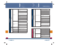
The guide contains the
following elements:
1. HEAT SOURCES
1
2. PIPING STRATEGIES
2
Disclaimer
This Technicians Service Manual is intended to assist you with an
overview of various systems and processes that incorporate Grundfos
products. The information presented here is only for illustration and
discussion purposes. The manual is not intended as a substitute for
the documentation that accompanies Grundfos products or other
products discussed in this publication.
Whenever undertaking any of the projects described here or using any
Grundfos product, you should always determine and comply with the
applicable building codes, permit requests, and other laws. There may
be national, state, or local codes that govern the installation of equipment set forth herein.
Boilers, furnaces, pumps, and other similar equipment are sophisticated products that require caution. Working with water, glycol and other
materials, alone or in conjunction with electricity, gas or other energy
sources, presents certain dangers both to persons and property. It is
critical that technicians, installers, system designers, and owners be
aware of all dangers inherent in the products and systems. You should
consult, understand, and heed all cautions, warnings, and danger designations that are listed in the product or process documentation.
Nothing herein shall be construed as a warranty, expressed or implied.
All Grundfos products carry warranties. You should consult the specific
product information to determine the terms of such warranties.
1
3. RADIANT HEATING
3
4. HOT WATER RECIRCULATION
5. PUMP SELECTION
4
5
6. INSTALLATION TIPS
6
7. TROUBLE SHOOTING
7
8. REFERENCES
8
2
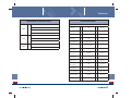
Content
1. HEAT SOURCES
Boiler types .................................................................................................................... 7 - 8
Solid fuel.......................................................................................................................9
Condensing - oil and gas.....................................................................................10
Converting steam to hot water .......................................................................... 11
Integrating condensing/modulation ...............................................................12
Annual maintenance .............................................................................................13
Direct hot water - Boiler generated .................................................................14
Indirect and direct water heaters ...................................................................... 15
Tankless water heaters ..................................................................................................16
Solar hot water ........................................................................................................ 17 - 18
2. PIPING STRATEGIES
Basic piping strategies ...................................................................................................19
Pumping away ................................................................................................................. 20
Primary, secondary, & tertiary .....................................................................................21
Series ....................................................................................................................................22
One-pipe distribution .....................................................................................................23
Parallel .................................................................................................................................24
Two-pipe direct return ...................................................................................................25
Two-pipe reverse return................................................................................................ 26
Zoning ..................................................................................................................................27
Zoning with circulators ................................................................................................. 28
Zoning with valves.......................................................................................................... 29
Injection ............................................................................................................................. 30
ALPHA pump..............................................................................................................31 - 32
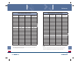
3. RADIANT HEATING
Introduction .......................................................................................................................33
Concrete slab .................................................................................................................... 34
Under-floor........................................................................................................................ 34
Above-floor.........................................................................................................................35
Walls and ceiling ..............................................................................................................35
Snow melting ............................................................................................................36 - 37
4. HOT WATER RECIRCULATION
New construction ...................................................................................................38 - 40
Retrofit solution ...................................................................................................... 41 - 42
Potable hot water recirculation ................................................................................. 43
Annual savings ................................................................................................................ 44
3
5. PUMP SELECTION
Determining metallurgy ...............................................................................................45
Static, dynamic, and total dynamic head ............................................................... 46
Selecting the right circulator .............................................................................. 47 - 48
UP10-16B5/BN5/BU ....................................................................................................... 50
UP15-10SU7P Comfort System ................................................................................... 51
UP15-10B5/7, BUC5/7 ......................................................................................................52
UP15-18B5/7, BUC5/7.......................................................................................................53
UP15-29 SU/SF ..................................................................................................................54
UP15-42B5/7, BUC5/7 ......................................................................................................55
UP(S)15-35, 55 SU/SF....................................................................................................... 56
UPS15-58, 26-99, 43-44................................................................................................... 57
UPS26-150, 43-100, 50-60 .............................................................................................58
UP15-42FC, BUC5/7 Miximizer ................................................................................... 59
UP15-42, 26-64, 26-96 Variable Speed .....................................................................60
ALPHA ......................................................................................................................... 61 - 62
MAGNA.......................................................................................................................63 - 64
VersaFlo UP ....................................................................................................................... 65
VersaFlo UPS .....................................................................................................................66
Dielectric isolation valves..............................................................................................67
Pump zone controls........................................................................................................ 68
6. INSTALLATION TIPS
Eliminating air .........................................................................................................69 - 70
Pump installation ............................................................................................................ 71
Thermal expansion tank sizing ...........................................................................72 - 73
Sizing water heater - tank and tankless.................................................................74
Calculating heat losses ..........................................................................................75 - 76
Outdoor reset ....................................................................................................................77
Pipe sizing...........................................................................................................................78
7. TROUBLE SHOOTING
Hot water systems and boilers ..........................................................................79 - 80
Circulators ................................................................................................................. 81 - 82
Baseboard heating ................................................................................................. 82 - 83
Valves .................................................................................................................................. 84
Water heaters, radiators ....................................................................................... 85 - 86
Noises ..................................................................................................................................87
Piping .................................................................................................................................. 88
Air, Outdoor reset control, recirculation, ................................................................. 89
8. REFERENCES
4
Introduction
BE
THINK
Be–Think–Innovate and Grundfos
INNOVATE
Be responsible
Being responsible is our foundation.
Grundfos is a company that changes as the world changes – but
our fundamental values remain constant. Over the years, our way
of doing things has proved to be successful. We have always been
innovative, we have always thought ahead and we have always been
responsible. Be–Think–Innovate – the values underlying these words
have consistently been a part of Grundfos, but now we want the world
to know: Be–Think–Innovate is Grundfos.
We know that we have a responsibility towards the people who are
Grundfos, towards the innovative soul of Grundfos, as well as towards
the surrounding world. Whatever we do, we make sure that we have a
firm and sustainable basis for doing so.
Think ahead
Thinking ahead makes innovation possible.
Guide to this Technician’s Handbook
Your time is valuable and we recognize that you are under more
pressure today to do more in less time than ever before.
That’s why we developed this booklet, which, by the way, is in direct
response to your expressed interest in it. You’ll find useful information
about hydronic piping strategies and circulation, charts, graphs, and
technician tips, all offered here to assist you while on the job.
We hope that technicians, installers, system designers, and owners
alike will value this resource. We designed it for tough service, just like
our products. Put it to use… and let us know what you think of it. We
value your insight and opinion. Visit our website and click on the “give
us your feedback” tab. See back cover for specific handbook websites.
5
We encourage a certain Grundfos way of thinking, which is founded
upon the belief that everyone must contribute by using his or her
judgment and foresight. We are looking for commitment and ideas in
everything we do so we can come up with the best solutions. We think
– and then we act.
Innovate
Innovation is the essence.
It is innovation that makes Grundfos unique. We stand out because
of our ability to constantly create new solutions to the ever-changing
demands of the pump business. We meet every challenge and we are
never afraid of taking the initiative – remaining true to our ideals calls
for renewal. Innovation is the soul of Grundfos.
6
Heat sources
1
Boilers are typically the heart of a contemporary hydronic system.
Atmospheric vented (newer style)
Boiler types:
Later generations of boilers became smaller while offering much greater energy efficiency. Internal flue passageways grew closer together
and with design improvements that further increased operational
efficiency. At the time of their development, these types of boilers
delivered 80% to 83% efficiency, considered then to be ‘high efficiency.’
Most were vented directly into chimneys.
• Atmospheric vented with draft diverter (chimney) – older style, low
efficiency non-condensing boiler, On/Off operation
• Atmospheric vented with draft diverter (chimney) – newer style,
medium efficiency non-condensing boiler, On/Off operation
• Indirect, side wall vented to exterior with fan assisted exhaust
– older style, low efficiency non-condensing boiler, On/Off operation
• Indirect, side wall vented to exterior, fan assisted (stainless steel
exhaust) – newer style, higher efficiency non-condensing boiler,
On/Off operation
• Direct vent, sealed combustion vented to the exterior, fan assisted
(stainless steel or plastic exhaust) – high efficiency condensing,
On/Off or modulating operation. Condensate drained by gravity or
pump
• Solid fuel boilers, wood/coal, indoor atmospheric chimney vented,
outdoor with exhaust stack and open relief or relief valved on water
side, normally isolated through a heat exchanger from the home’s
hydronic heating system
Boilers – atmospheric vented (old style)
Built long before fuel efficiency was a concern, their internal passageways were designed to handle raw gases, soot, and smoke from solid
fuels. Heating of domestic water was typically accomplished by gravity flow to a storage tank.
Old chimneys are often unlined; it’s vitally important to check the base
each year to remove debris; this protects against infiltration of CO2
and other by-products of combustion.
7
1
As developments continued, new boilers soon exceeded to 85% efficiency range. But with system advancements, a key change involved
the lowering of boiler flue gas temperatures. As these cooler exhaust
gasses enter old chimneys, condensation can form easily (when flue
temps fall below 350°F, the formation of acidic condensate becomes a
constant challenge and can ruin masonry chimneys, especially those
that are older and unlined). A flue liner must be installed to protect
the occupants. Aluminum may be used for gas-fired systems and
stainless steel must be used for oil.
Boilers – indirect side wall vented (low efficiency)
These systems offer no improvement in efficiency, but give greater
flexibility when placing a boiler where a conventional chimney is not
available.
Boilers – indirect side wall vented (high efficiency)
These boilers provide higher efficiency operation. Venting material
changes to high temp plastic or stainless steel. Boilers, for the first
time, now include a secondary heat exchanger within the exhaust
stream to harvest waste energy, greatly improving efficiency.
Boilers – direct vent, sealed combustion (higher efficiency)
These systems – designed to achieve mid-90s efficiency – extract a
significant amount of waste energy from the waste stream. These
boilers are ideal for low temp hydronic systems, such as radiant heat
and snow melt. One of the latest advancements is modulation of
the burner. No longer an on/off appliance, these boilers dramatically
reduce fuel use and can actually match heat output to the building’s
heat loss. Flue gas temps are often well below 350°F. Stainless steel or
aluminum is the required venting material. Condensate is acidic and
must be neutralized before drain discharge.
8
Heat sources
1
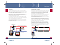
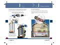
Solid fuel
Condensing – oil / gas
Wood- and coal-fired boilers can be open or closed systems. Open
systems tend to be large in water volume and located outdoors. Wood
varies in BTU content, depending on the species and moisture content.
Coal also varies in BTU content due to impurities.
The emergence of early condensing boilers began in this country about
one decade ago. A few cast iron models were available with efficiencies approaching 90% and required stainless steel indirect venting.
Draft inducer fans drew combustion gases through the boiler and
rejected the gases to a sidewall vent termination.
Open systems use a heat exchanger loop when connected to a
building’s hydronic system. If subjected to freezing temperatures, the
loop must be filled with a glycol solution.
Closed systems can be made to work in conjunction with an existing
hydronic heating system and must be provided with an uninterrupted
means for moving energy from the solid fuel boiler.
A relief valve with a BTU rating that equals or exceeds the maximum
BTU capacity of the vessel and its fuel must be installed to direct any
discharge away from people.
Controlled by room
thermostat
Check valves permit dual/individual use
1
More recently, these systems have advanced technologically and are
plentiful. Stainless steel is used for many of the heat exchangers
and extract sufficient heat from the combustion process to maintain
exhaust temperatures well below 350° F.
Condensate is mildly acidic and must be neutralized before discharging into metal drain line piping. This new generation of condensing
boilers can achieve mid-90% efficiencies. They’re ideally suited for low
temperature radiant heat and snow melt systems.
One of the latest advancements to these systems is modulation of
the burner. No longer an on/off appliance, these boilers are adept
at dramatically reducing fuel use. Venting requirements vary widely
between manufacturers, as do piping and pumping needs. Setting up
combustion using a calibrated combustion analyzer is necessary to
ensure proper boiler function.
Controlled by
aquastat only
Relief valve sized
properly and safely
Solid fuel boiler
Add strainer
Neutralizer
Condensate drain
9
10
Heat sources
Converting steam to hot water
1
Many two-pipe steam systems can be converted to hot water. Energy
savings can be dramatic if a modulating condensing boiler is used.
If the radiators are connected across both the top and bottom, you can
begin to determine if hot water heating is an option. The first step
requires a complete room-by-room heat loss and survey of the heat
emitters to ensure they’ll meet design-load conditions.
Each radiator will need to have the older-style steam valve replaced
and either the bellows removed from its trap or replaced with a return
union/elbow. Many cast iron radiators were designed to be used for
steam or hot water and will have a threaded plug near the top of one
end section. This can be removed by center-drilling the plug and gently
extracting it. A loose-key air vent can then be installed and the radiator made ready for service by tightening both supply/return unions.
Integrating condensing/modulation with older
systems
Existing high-temp hydronic systems with baseboards, convectors, or
cast iron radiators can be switched over to condensing, modulating
operation.
The first step requires a room-by-room heat loss survey; be sure to
include each room’s existing heat emitter. Each type of heat emitter
will have a limited amount of BTU output, which will be based on its
size and heating curve. By using the charts included in this booklet,
you can determine the output of each room’s heat source at varying
water temperatures. Once you’ve completed the heat loss survey and
know that room’s BTU load, the heat emitter’s capacity will determine
how low you can go with water temperature delivery.
Rust and debris will likely find their way to the boiler; installation of
a strainer is recommended. Replace the strainer’s plug with a boiler
drain to quickly blow-down the unit’s screened compartment.
The ∆T across each heat emitter can be quickly determined by subtracting the BTU output from the GPM flow rate. The purpose behind
the math? If you can keep the return water’s temperature below 140°
F (what is needed to achieve condensate heat recovery within the
boiler), you’ll maximize the “mod-con’s” energy efficiency.
Once filled with water, any leaks can be found. It’s a good idea to tell
the owner that this is a possibility and, if so, repairs will be necessary.
A homeowner may also enjoy knowing that a hot water system – especially if you’ve used outdoor reset – will be safer, more comfortable,
and more energy
gy efficient.
The addition of a Y-strainer to capture water-borne debris is recommended. Primary/secondary piping is an excellent method to ensure
the boiler has the required GPM flow rate at all times.
Hot water
1
Cut & connect new piping
Steam
Add strainer
Cut and connect new piping
Neutralizer
11
Condensate drain
12
Heat sources
1
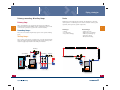
Annual maintenance
Direct hot water – boiler generated
Most heating systems suffer from neglect. As you well know, homeowners often forget about mechanical systems – until there’s a crisis.
Lucky you! Here are some tips that may help you on the job.
There are a number of boiler manufacturers that offer models which
also heat potable water.
Older style boilers often vent into chimneys:
•
•
•
•
Clean and inspect flue passageways and exhaust piping
Inspect piping, circulators, and controls
Inspect and clean chimney
Perform combustion analysis
Indirect-vent boilers (non-condensing):
In addition to the above . . .
• Exhaust vent piping must be adequately supported (no sags)
• Exhaust termination points - inspect for blockages: bee’s nests,
rodents, perimeter clearance from landscaping, and potential for
snow drifting/accumulation
Direct-vent condensing boilers:
In addition to the above . . .
• Open combustion chamber to chemically clean all internal passageways
• Inspect and clean condensate trap/drain line
• Inspect and verify condensate pump operation (if present)
• Clean or replace flame sensors and/or probes
• Recharge condensate neutralizer
• An electronic combustion analyzer must be used for proper combustion analysis, operation, and to maintain peak efficiency
• Print out results to document your work
Solid fuel boilers:
• Thoroughly clean all interior combustion and flue passageways
• Inspect and clean chimney, flue piping, and anything used to
transport exhaust gases
• Relief valves should be tested
• Test glycol for pH level
• Inspect door gaskets, controls, and circulators
13
1
Some use a three-way valve to divert hydronically heated water
through a flat-plate heat exchanger to produce hot potable water;
the GPM flow rate is dependent upon net BTU input from the boiler
(see tankless water heaters). During production of potable hot water,
hydronic heating zones are disabled so that the boiler’s full energy is
prioritized to making potable hot water. Temperature fluctuations and
the potential for scalding make it important to use an ASSE 1016/1017
thermostatic scald-guard.
Other models have dual storage tanks – a tank within a tank – to
maintain separation between the hydronic and potable waters.
Heat-energy is transferred directly through the walls of the two tanks.
A time-out feature can be programmed to temporarily shut down
hydronic zones while domestic potable hot water is in use. While potable hot water outlet temperatures tend to be relatively stable, they
will often be within scalding ranges, so be sure to use an ASSE certified
1016/1017 thermostatic scald-guard.
Hydronic
supply
Hydronic
return
Motorized
3-way valve
Potable cold in
Potable hot out
ASSE 1016/1017 valve
14
Heat sources
1
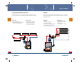
Indirect and direct water heaters
Tankless water heaters
Basic indirect and direct storage-tank water heaters have a well insulated tank and lose very little heat to the surrounding area. Both types
must be connected to an external energy source that generates heated
water.
Tankless water heaters heat water on-the-fly. If you apply the BTU
ratings for the fuel type, know the ∆T and the appliance net input, the
maximum delivery flow rate can be determined.
On average, an indirect tank has an internal coil through which hydronically heated water is circulated. A sensor or aquastat is used to
monitor the storage temperature and activate/deactivate the external
energy source. A properly sized circulator is used to move energy from
the heat source through the tank’s coil. The circulator should pump towards the highest head loss. GPH rating for heating potable water will
be dependent on the GPM flow rate through the coil and the delivery
temperature from (and net BTU rating of) the energy source.
On systems with a direct style storage tank, potable water is circulated
through the energy-producing device to maintain temperature. All
components must be rated for direct contact with potable water. Circulators must have bronze or stainless steel impellers and water-ways
and must be sized to meet the required GPM.
•
•
•
•
•
Presdrop may create the need for a booster pump
Venting requirements must be followed exactly
In retrofit applications, gas and electric lines must be increased
Not suitable for use with aggressive or high mineral content water
Direct recirculation is not recommended due to high head loss
* Consult tankless manufacturer’s recommendations before installing
recirculation system.
• If an quastat and timer is not used, the electric water heater may
not have enough recovery rate to keep up with BTU losses.
Example: Indirect recirculation
To point of use
Meeting peak demand determines the sizing. As the storage tank volume increases, the net BTU rating of the heat source can be decreased.
Multiple storage tanks can be combined with a single heat source to
increase peak-demand storage.
1
Aquastat
Tankless potable
water heater
Timer
Dedicated
return
line
6-8 gal. electric
water heater
15
16
Heat sources
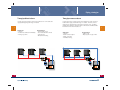
Solar hot water – storage tank
1
1
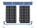
Three basic types of solar panels are the vacuum tube, flat enclosed
panel, and soft roll mat. Vacuum tube array panels offer some of the
highest efficiencies and potential for the hottest water (in excess of
160° F). Flat enclosed panels are less expensive and produce slightly
lower temperatures, while soft roll mat panels are typically used for
pool heating applications.
Potable
Hot out Cold in
Common to all three: panels work best in a south-facing orientation.
Storage volume is chiefly dependent on panel style, number of panels,
solar radiation (amount of sunshine), lifestyles of the occupants, and
other sources of hot water.
In warm climates where freezing is not a concern, the entire solar heat
system (including the tank) may be located on the roof, or collectors
may be lower in elevation than the storage tank. All other types will
incorporate one or more circulators to move heated water.
ASSE
1016/1017
In areas subject to freezing temperatures (solar panels can freeze at
temperatures below 32° F), the solar heat system will either be pressurized and filled with a glycol/water mixture or self-draining to a tank
that can accept the drained volume without overflowing.
Heat exchanger
Stored water is often above scalding temperatures. An ASSE-1016/1017
certified scald-guard mixing valve is required to regulate delivery
temperatures. A differential temperature control turns the pump(s) on
and off when the solar collector temperature rises above stored water
temperature.
Overflow
receiver
Solar
storage
tank
17
Auxiliary
water
heater
18
Piping strategies
2
Basic piping strategies
Pumping away
Piping is used as the energy-transportation network. Its job is to
permit sufficient flow to move enough BTUs within a given time frame
so that comfort levels can be maintained under design conditions.
Once you’ve calculated the heat loss, the design process and installation methods you choose will determine pipe sizing.
In any hydronics system, the point where the thermal expansion tank
joins the piping is called the “Point of No Pressure Change”. Since
water cannot be compressed or stretched, no water can leave the hydronic loop when a pump starts/stops. Circulator pumps create a pressure differential when running, which upsets the pressure balance and
causes fluid to flow. The pump’s differential pressure will be added to
the loop if it is installed after the thermal expansion tank – Pumping
Away.
Manufacturers of pipe and tubing provide flow charts detailing maximum flow rates and head loss per foot for various sizes. Size matters:
maximum tubing lengths are limited by flow rate and total head loss.
If multiple loops are attached to a single manifold, the highest head
loss of any single loop is the number used when selecting a pump to
serve this manifold.
Circulators create a pressure differential that induces flow. The combined GPM flow rate required and single largest head loss determine
which pump is the best match.
2
The added pressure causes air bubbles to shrink, which makes them
less buoyant and helps carry them through the loop where they can be
removed by an air elimination device such as an automatic air vent or
separator. Pumping Away helps eliminate air, enhances quiet performance, and helps systems run more efficiently.
Warning: Pumping towards a thermal expansion tank has the opposite
effect: pressure will decrease at the system’s highest elevation; air
bubbles will expand and gather together; noise will be created during
operation; customers will complain; nuisance no-heat calls will occur;
and the potential to damage system components will be present.
Pumping Away – Piping
19
20
Piping strategies
2
Primary, secondary, & tertiary loops
Series
Primary loop:
All fluid passes throughout this network. Air elimination is critical at
start-up and on a continuing basis in order to maintain comfort, quiet
operation, and to protect system components.
This is normally the loop connected to the heat source with the
thermal expansion tank. Multiple boiler configurations may each be
connected to a primary loop (see boiler section for details).
Secondary loops:
These are connected to the primary loop and serve separate heating
loads.
Tertiary loops:
2
Advantages:
• Simple
• Less expensive
• Easy control strategy
Disadvantages:
• Single zone only
• High head loss potential
• BTU drop-off along loop
• Flow rates critical
• Over/under heating
These can be connected to secondary loops, as in the example below,
where the return water temperature from the baseboard loop is the
required supply temperature for the wall-panel radiator.
Primary
Secondary
21
Secondary
Tertiary
22
Piping strategies
One-pipe distribution systems
Parallel
Flow of water (BTUs) is accomplished by using tees with flow restrictors that cause some of the water to divert through the heat emitter.
Balancing for equal flow through parallel piping loops is accomplished
by installing balancing valves or reducing/increasing pipe size in the
supply/return lines
Advantages:
• Reduced material cost
• Individual heat emitter control
• Enhanced heat distribution
Advantages:
• Simple
• Moderate cost increase
• Easy control strategy
• Individual heat emitter control
• Easy to balance heat output
• Consistent temperature supply
2
23
2
Disadvantages:
• High head loss potential
• BTU drop-off along loop
• Flow rates very critical
• Air elimination difficult
Disadvantages:
• High head loss potential
• Flow rates more critical
• Velocity noise
• Pipe sizing more critical
24
Piping strategies
Two-pipe direct return
Two-pipe reverse return
In a two-pipe direct return system, heat emitters are connected to the
supply/return piping like rungs of a ladder.
In a two-pipe reverse return system, heat emitters are still connected
between the supply return like rungs on a ladder. However, reverse
return has its supply/return connected at opposite ends – pushing/
pulling with equal force through all the connected heat emitters that
have identical or similar head losses.
2
Advantages:
• Simple
• Control heat emitters individually
• Zoning is possible
25
Disadvantages:
• Flow balance issues
• Uneven distribution of heat
• Velocity noise
• Over/under heating
Advantages:
• Simple
• Balanced heat output
• Quiet, even flow
• Individual zoning
2
Disadvantages:
• Higher cost
• May require a by-pass valve
26
Piping strategies
2
Zoning
Zoning with circulators
Zoning can be accomplished by using circulators, motorized valves,
manifold telestats, or solenoid valves, giving owners/occupants more
control to manage room-to-room comfort levels. Zoning reduces
energy consumption by heating only spaces during operatorprogrammed time periods.
Not long ago, it was more complicated and expensive to zone with
circulators than it was with zone valves. Not any more. Today’s compact wet-rotor circulators are extremely versatile, rugged, and no more
expensive than zone valves. Circulators are available in multi-speed,
and with or without integral flow checks. Add air purge and isolation
flanges and you’ll soon see how simple air elimination can be. Servicing a single circulator is quickly accomplished without interrupting the
operation of other zones.
Advantages:
• Reduced energy cost
• Independent control of space
• Design flexibility
Example 1:
Disadvantages:
• Higher installation cost
2
Zoning with circulators offers the ability to deliver multiple temperatures from either a single-source set-point or graduated temperatures
from a primary loop with outdoor reset. As the reset curve changes, so
will the mixed-down temperatures – allowing the secondary circuits to
use the same reset ratio. The highest temperature zone becomes the
reset target temperature and determines the reset ratio.
Multi-speed circulators, like the SuperBrute, allow the designer or installer to adjust flow rates for reduced energy consumption and silent
operation. In fact, the SuperBrute lineup, each with a flip-of-a-switch,
three-speed adjustability, offers versatility unmatched in the industry.
These multi-speed circs improve your ability to do more with less –
reducing inventory and increasing profits.
Example 2:
27
28
Piping strategies
Zoning with valves
2
Injection piping
Properly sizing a circulator includes totaling all zone-connected circuit
GPM flow rates and the single greatest resistance to flow in any of
the connected circuits. As zone valves open/close, flow rates and fluid
velocities vary. Most zone valves need to close against flow to avoid
slamming shut.
In order to avoid flow and velocity related noises, a differential by-pass
regulator may be needed. As valves close and head increases, the bypass regulator opens to maintain proper flow/velocity.
Injection piping serves as a thermal bridge between two circuits for
transferring BTUs. Being hydraulically separated, the primary and
secondary circuits can have varying flow rates with no affect on the
other. The injection bridge circuit can also operate at a different flow
rate. If the ∆T is allowed to widen, more BTUs can be transferred over
the injection bridge at lower flow rates. With low flow rates required
to transfer large amounts of energy, the injection bridge will allow
manifolds serving large areas to be remotely located, away from the
mechanical room.
2
Note 1: Reduced diameter injection piping (supply and return).
Circuits can be quickly charged by installing a purge valve on the main
return or on individual returns to eliminate air. A single purge fitting
can be used to quickly charge all zones.
Advantages:
• Manifold zoning
• Less expensive
Disadvantages:
• Wiring can be difficult
• May require larger transformer
• Frequent replacement
• System debris failure
• Drain system to replace
• Frequent leaks
Zone valves
By-pass
relief valve
assembly
Note 2: There must be a maximum of 6 pipe diameters between the
tees in the boiler and system loops in order to prevent heat migration
(ghost flow).
Note 3: There must be at least 6 pipe diameters of straight pipe on
either side of the tees in order to prevent turbulent flow which could
encourage heat migration.
Note 4: To prevent heat migration through the injection loop, there
should be a minimum 18-inch drop to create a thermal trap.
Reset controller
Outdoor
reset
3
Supply
sensor
1
4
Purge valve
1
2
3
Boiler
return
sensor
29
Purge valve
Manifold telestats
30
Piping strategies
ALPHA™ Pump
2
A new generation of piping strategies will emerge with the Grundfos
ALPHA pump. By incorporating a permanent magnet motor design,
power consumptions are now reduced by a minimum of 50%. Utilizing the AUTOADAPT™ control feature will ensure automatic hydraulic
adjustments to system demand changes.
Differential pressure
by-pass valve
not required
Usin
Using the ALPHA™
pum
pump in a controlled
mod
mode, will eliminate
the n
need for
diffe
erential pressure
by-p
by-pass valves.
2
Seven hydraulic control options
• 3 Fixed speeds
• 3 Constant pressure settings
• AUTOADAPT ™
Easy-to read LED displays
• Power consumption
• Flow indicator
• Seven hydraulic settings
Simple plug in design for power connection
P
Differential pressure
by-pass valve
not required
31
Constant pressure or
AUTOADAPT™ mode, will
automatically adapt to meet
eet
the demands of your heating
ting
system. By measuring and
d
analyzing power demands,
s,
pumping speeds are adjusted
sted
to maximize comfort levels
els
and energy consumption..
32
Radiant heating
3
Radiant heating
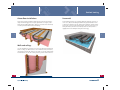
Concrete slab installations
In a radiant heating application, liquid is pumped through distribution
piping, providing heat to be transferred to floors, walls, or ceilings.
These surfaces radiate heat in all directions, with warmth always moving to colder, solid objects.
Tubing layouts vary widely. The intent, ideally, is to run warmest water
along the coldest sides first. Rooms with a single exposed wall might
be served by a simple back and forth serpentine loop. For long walls or
multiple exposed walls, two loops (or more) can be run in a counterflow pattern with each loop’s water flowing in opposite directions to
minimize any noticeable floor temperature difference.
The water temperature for radiant heating systems is typically much
lower than what’s used with other types of heat transfer – such as
with radiators and baseboard systems. Putting heat where it’s most
needed and the use of lower liquid temperatures improves comfort,
control, and reduces energy consumption.
3
It’s not uncommon for a radiant system to vary its water delivery temperatures from 75° F to 140° F to offset building heat losses. During
the heat loss calculation and design phase, a reset ratio is calculated
to determine the upper and lower water delivery temperature limits.
Floor surface materials must be considered and will affect the rate of
heat transfer.
Multi-speed, low wattage circulators, like the SuperBrute, give you
greater flexibility to match wide varieties of required flow/head rates
for floor, wall, and/or ceilRadiant vs. Forced air heating
ing applications.
There are a number of
installation methods for
radiant heating applications. Each one provides
varying degrees of
energy efficiency and
comfort. The correct
application will be the
one that most closely
matches a given installation and its design.
Under-floor installations
There are four basic types of installation for under-floor designs:
suspended tube, staple-up, thin plate, and extruded plate. Thermal
performance varies between each style.
y Insulation installed below the
tubing
bing directs heat upward through the flooring materials.
The finished surface materials will determine
maximum allowable
water temperatures.
33
34
Radiant heating
Above-floor installations
Snow melt
There are four basic installation applications for above-floor designs:
staple-down with gypcrete over-pour, plated tube on sleepers, structural sub-floor with built-in tube channels, and several non-structural,
over-floor products with channels for tubing.
Snow melting systems are a popular addition to hydronic systems. In
some cases, the snow melting load will be far greater than the home
or business heating needs. This may mean installing a separate standalone heat source for snow melting. Glycol solutions are more viscous
than plain water, which increase head (resistance to flow) and also
slightly
heat-energy.
g y reduces the abilityy to transport
p
gy
3
3
Walls and ceilings
In some installations, it may be necessary or desirable to run tubing in
walls or ceilings to offset heat loss. For a walk-in shower, for instance,
it may be best to heat all surfaces for a warm cocoon-like environment.
Towel warmers can also be used to p
provide a p
portion of the heat load.
35
36
Radiant heating
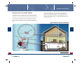
Hot water recirculation
Snow melting
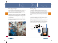
Why wait for hot water?
Snow melting systems are sometimes required for safety in public
areas and helipads at hospitals. Residential snow melting systems are
a popular addition to hydronic systems. In some cases, the snow melting load will be far greater than the home or business heating needs.
This may mean installing a separate stand-alone heat source for snow
melting. Or, for a swimming pool, you could offer the temperature
conditioning to extend the swimming season.
There are three key reasons your customers should want a “recirc”
system:
3
It saves water – It saves money – It saves time
The average home wastes 11,461 gallons of water per year due to
unnecessary wait for hot water to reach showers and faucets. Installation of a dedicated hot water return line, “recirc” system, means a
continuous flow of hot water without having to wait.
Fresh water is a precious natural resource that is slowly being depleted. In many parts of the world, stringent water conservation is
already a part of everyday life. Even in the U.S., rising populations and
arid climates in some Western states have resulted in higher costs
and stronger focus on water conservation. Hot water recirculation is a
cost-effective method of controlling and additional waste of water.
4
Glycol loop
Snow melt
circuit
Neutralizer
Condensate drain
Liquid glycol solutions are more viscous than plain water, which
increases head - resistance to flow - and also slightly reduces the ability to transport heat-energy (see glycol information in the pumping
section). Condensing modulating boilers are often used for these lowtemperature applications because they do not require boiler flue gas
condensation or thermal shock protection. Hydronic glycol pH should
be tested annually. Thermal expansion is greater when glycol is added
and the expansion tank must be rated for use with glycol.
37
38
Hot water recirculation
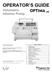
One preferred method is by installing a pump with Timer and Aquastat
on the return line. This method of installation will ensure maximum
energy savings when both controlling limits are satisfied, fluid temperature observed by the aquastat, and the timer setting.
Pump with Timer and Aquastat
For new construction
One possible solution is the UP10-16 for new homes, designed
with dedicated return lines. The one-piece HWR solution is easily
installed at the water heater. This innovative pump comes with
an integrated aquastat and timer to meet your customers specific
demands.
Isolation
Valve
Integrated
Aquastat
4
Hot
water
+RWZDWHU
supply
to
VXSSO\WR
KRXVH
house
Timer
Integrated
Aquastat
Pump
Timer
&ROGZDWHUVXSSO\
Cold
water supply
Hot
water return line
+RWZDWHUUHWXUQOLQH
Check Valve
Hot water
+RWZDWHU
VXSSO\WR
supply to
KRXVH
house
4
Cold water
&ROGZDWHU
VXSSO\
supply
Hot water
+RWZDWHU
UHWXUQOLQH
return
line
Purging a hot water recirculation system is very imprtant
upon installation. Ensures
proper operation of the pump
and system components.
39
40
Hot water recirculation
Hot water recirc: the retrofit solution
The Comfort System is a one-pump, one-valve combo that’s typically
installed in one hour – without the need to install a return line to the
water heater, or an electrical connection outside the mechanical room.
The unit begins working when the timer-activated pump at the hot
water tank pushes hot water toward a valve beneath the furthest
fixture in the house. The valve connects the hot and cold water supply
lines.
4
As long as the water in the hot line remains cold, the valve stays
open and the cold water is sent back to the heater through the cold
water line. Hot water stands ready to come out when the tap is
turned on. Contractors also appreciate the fact that there’s no need
for electric service under the sink – a common requirement for other
recirculation systems.
Typical Comfort System installation
4
Bypass
valve
Flex hose
ater
Hot water
ply
supply
Pump
ump
Cold w
ate
er su
upp
water
supply
Timer
Hot Water Tank
For more information on either system, go to www.SaveWaterNow.com
41
42
Hot water recirculation
4
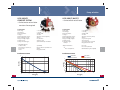
Potable hot water recirculation
Example 1:
A common homeowner complaint is the long wait for hot water in the
bathroom. Frequently, that wait can last for one or two minutes. Toss
in a family with several bathrooms, and the potential exists for large
volumes of water to be wasted. Our chart with the calculation based
on pipe size, length of run, and daily usage indicates 9,855 to 55,115 gallons of wasted water per year (www.SaveWaterNow.com).
Operating costs for recirculation – constant circulation:
• 25W circulator running 24/7/365 costs $20.15 at $.092 kWh
• Average annual heat loss cost $138.33 (1/2-inch copper tubing covered with 1/2-inch fiberglass insulation)
Annual savings: $275.12 - $20.15 - $138.33 = $116.64
Hot water recirculation system applications:
• 24/7/365 constant circulation with a dedicated return line
• Dedicated return line with an aquastat to turn the pump on and off
• Dedicated return line with timed pump circulation
• Hot-to-cold timed circulation with an aquastat to limit the cold
water line’s temperature
• Thermal by-pass systems can be motion-sensor, infrared, or
manually activated
Example 2:
Operating costs for recirculation – timed circulation:
• 25W circulator running 2 hours per day costs $1.68 at $.092 kWh
• Average annual heat loss cost $14.62 (1/2-inch copper tubing covered
with 1/2-inch fiberglass insulation)
Annual savings: $275.12 - $1.68 - $14.62 = $258.82
4
Why is it important?
Water use:
• An average home over 2,000 square feet has 125 feet of 3/4-inch pipe
• 125 feet of 3/4-inch Type L copper pipe holds 3.14 gallons of water
• 10 draws per day wastes about 31.4 gallons of water
• Over a year, the use equals 11,461 gallons
• 25.2 million homes waste 288,817,200,000 gallons of water per year
Wasted water cost analysis:
• Assume 12,000 gallons water wasted per year
• At $.007 per gallon, that comes to $84 down the drain
• At 82% efficiency, heating water from 55° F to 140° F costs $138.33
(natural gas costs $.01335 per 1 cu. ft.)
• Add yearly sewage treatment cost of $52.79
• The total wasted-water-cost would come to $275.12
The system’s initial cost and fees to install an electrical outlet may
seem like a deal-killer. But if you promote the return on investment,
your sales will increase. ROI is calculated by dividing the system’s cost
into the annual fuel savings. If you project an annual saving of $100
and the system costs $600 installed, the ROI is an attractive 16.7%,
which is also a tax-free ROI.
43
38
39
44
Pump selection
Determining metallurgy
Static, dynamic, & total dynamic head
One aspect of your pump selection should be determining the metallurgical makeup of your pump. What should your metallurgy be, based
on application, fluid medium, and any governing standards?
The term “head” is used often and has many different meanings – no
wonder it’s confusing. Let’s untangle the head knot a bit.
Static head:
First Step:
Defined as the pressure required to adequately fill the hydronic system. Static head needs to be greater than the highest elevation within
the hydronic system.
• Will this be an Open or Closed system?
• Open system is defined as a piping system moving fresh
water or is exposed, at any point, to atmosphere - specifically oxygen.
One PSI will cause water contained in a column to rise 2.31 feet. You’ll
often see the rise in feet shown as ‘altitude’ on gauges. 12 PSI = 27.72feet of static pressure. Static head does not relate to the selection of
circulators.
• Closed systems are hermetically sealed piping systems,
fresh water is never required after commissioning and is
usually pressurized. No interaction with the atmosphere.
Dynamic head:
Second Step:
Defined as one half of the required information to properly select
circulators. Hydronic systems move liquid containing heat-energy from
the heat source to all points where warmth is needed. Pressure-energy
is exerted by circulators to meet or exceed resistance to flow (dynamic
head) to move the liquids at required GPM. The pathway from heat
source to areas where heat is needed (or points of comfort) and back
again creates a loop.
• What is the fluid being pumped?
• Fresh water, chemical (pH), glycol, etc…
Third Step:
5
• Any federal, state, or local standards governing metallurgy?
• Some states are requiring “lead free” or only traceable
amounts of lead present in potable pumping systems.
The following parameters may influence your metallurgical selection
• Aggressive carbon dioxide CO2 , chloride CL• Free chlorine CL2
• Oxygen O2
• Acidity pH
• Hydrogen sulphide H2S
• Temperature
Within each loop, there are multiple sources of friction that create
resistance to flow (dynamic head). Look for the one component that
has the highest resistance to flow. Examples: longest single length of
PEX connected to a manifold; mixing valve; total developed length of
supply/return piping; heat emitters; or monoflow tees. As GPM flow
rates change, the dynamic head will also change.
Common metallurgy available, corrosion resistance increasing left to
right
Total dynamic head:
5
Each component through which hydronic fluid passes has a specific
“dynamic head.” This number will increase or decrease as flow rate
increases or decreases. Once you know the GPM flow rate, you need
to determine total dynamic head – often expressed as “head losses” or
“feet of head,” a number arrived at by adding up the various dynamic
head losses for all components in that loop.
Cast iron -> Bronze -> Stainless steel
GPM rates, along with total dynamic head, are the two factors used
when selecting circulators (See next page).
45
40
46
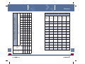
Pump selection
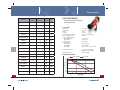
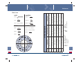
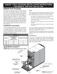
Selecting the right circulator, made easy
By now, you have completed several steps along the path to selecting
the best circulator that will use the least amount of energy to overcome dynamic head.
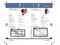
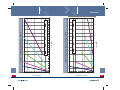
Example 3:
Head loss 3/4-inch copper = .04/100 ft. @ 170°F. 150-foot total equivalent length; 150 x .04 = 6-foot of dynamic head and 4 GPM is required.
Find the intersecting points for 6 feet of total dynamic head and 4 GPM.
Low speed is correct.
The heat loss, fluid temperature, and potential BTU output of the
heat emitter(s) determine GPM flow rates, which guide you toward
circulator selection. In the following examples, we’ll use the UPS1558 SuperBrute. You will see three colored bands that represent three
different speed ranges (Hi-Med-Low). Reference the dotted lines for
applications when integral flow-checks are required.
LOW SPEED
Example 1:
At 1 GPM and 140° F fluid temperature, head losses for the 3-way
valve is rated at 15.5 feet, piping 1-foot, and radiator 2-feet. Find the
intersecting points for 18.5 feet of total dynamic head and 1 GPM.
High speed is correct.
SuperBrute UPS15-58F/FC performance curves
HI SPEED
20
5
Without Check Valve
18
5
With Check Valve
16
14
12
Head (ft.)
Example 2:
Assume a total flow requirement of 5.6 GPM (1.4 GPM per loop). Head
loss 5/8-inch Pex @ 1.4 GPM = .03 per foot. 350 feet of Pex x .03 = 10.5
feet of head. Find intersecting point for 10.5 feet of total dynamic head
and 5.6 GPM. Medium speed is correct.
10
8
HI
6
Med
4
Low
2
MED SPEED
0
0
1
2
3
4
5
6
7
8
9
10
11
12
13
14
15
16
17
18
Flow (GPM)
47
48
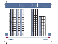
Pump selection
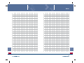
Flow Range
(GPM)
Head
Range (ft.)
UP10-16
0 - 2.5
0-5
50
UP15-10SU7P
0 - 6.5
0-6
51
UP15-10B/BUC 5/7
0 - 8.5
0-6
52
UP15-18B/BUC 5/7
0 - 15
0 - 14.5
53
UP15-29
0 - 22
0 -10
54
UP15-42B/BUC 5/7
0 - 18
0 -15.5
55
UPS15-35
0 - 21
0 -12
56
UPS15-55
0 - 24
0 -18
56
UPS15-58
0 - 18
0 - 19
57
UPS26-99
0 - 33
0 - 30
57
• Standard features:
UPS43-44
0 - 64
0 - 14
57
• Optional features:
UPS26-150
0 - 52
0 - 47
58
Performance curves
UPS43-90
0 - 60
0 - 31
58
UPS50-60
0 - 110
0 - 21
58
UP15-42 MR/VS
2 - 36
2 - 30
59-60
ALPHA™
0 - 22
0 - 19
61-62
MAGNA
0 - 170
0 - 42
63-64
VersaFlo UP/UPS
0 - 240
0 - 62
65-66
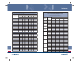
Page
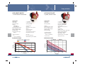
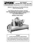
– for hot water recirculation
with return line
Technical data
Flow range:
Head range:
Motor:
Voltage:
Fluid temperature range:
Max. working pressure:
Flange to flange length:
UP10-16B5/BN5
UP10-16BU
Pump housing:
Connection type:
UP10-16B5
UP10-16BN5
UP10-16BU
3-1/8 inches
4-1/3 inches
Brass MS 58
1/2-inch sweat
1/2-inch FNPT
GF 125 union - 1-1/4” NPSM
5 foot line cord w/plug
Mating flanges available
Timer, aquastat
43
5
UP10-16BU
5
4.5
4
3.5
3
2.5
2
1.5
1
0.5
0
49
0 - 2.5 GPM
1 - 5 feet
25W
1 x 115V
36°F (2°C) to 203°F 95°C
145 PSI
UP10-16B5/BN5
Head (ft.)
5
MultiSpeed
UP10-16B5/BN5/BU
Model
0.5
1
1.5
Flow (gpm)
2
2.5
3
50
Pump selection
UP15-10B5/7, BUC5/7
UP15-10SU7P
COMFORT SYSTEM
– for hot water recirculation
– for hot water recirculation
no return line required
5
Technical data
Flow range:
Head range:
Motor Hp, watts:
Voltage:
Fluid temperature range:
Max. working pressure:
Flange to flange length:
Pump housing:
Pump connection type:
0 - 6.5 GPM
0 - 6 feet
1/25Hp, 25W
1 x 115V
36°F (2°C) to 150°F (66°C)
145 PSI
5-7/16 inches
Stainless steel
3/4-inch M X 3/4-inch FNPT
• Standard features:
Isolation valve:
Flex stainless steel hoses:
Power cord:
Timer:
1/2”M NPS
(2) 1/2” FNPS x 1/2”FNPS x 12”
10 feet
Integrated 24-Hr.
Technical data
Flow range:
Head range:
Motor Hp, watts:
Voltage:
Fluid temperature range:
Max. working pressure:
Flange to flange length:
Pump housing:
Connection type:
BUC5/7
• Optional features:
*
5
Performance curves
UP15-10B5
UP15-10BUC5
7
6
7
5
6
4
Head (ft.)
Head (ft.)
Line cord
Line cord w/timer
Max fluid temp. 150°F (66°C)
* Line cord w/timer:
Performance curves
3
2
UP15-10B7
UP15-10BUC7
5
4
3
2
1
1
0
0
0
51
0 - 8.5 GPM
0 - 6 feet
1/25Hp, 25W
1 x 115V
36°F (2°C) to 230°F (110°C)
145 PSI
See product guide
Silicon bronze
1/2-inch & 3/4-inch sweat
Integrated check valve
2
4
Flow (gpm)
0
6
44
45
3
6
Flow (gpm)
9
52
Pump selection
5
UP15-18B5/7 BUC5/7
UP15-29 SU(1)/SF(2)
– for hot water recirculation
– for hot water recirculation
Technical data
Flow range:
Head range:
Motor Hp, watts:
Voltage:
UP15-18B5/7
UP15-18BUC5/7
Fluid temperature range:
Max. working Pressure:
Flange to flange length:
Pump housing:
Pump connection type:
BUC5/7
Technical data
Flow range:
Head range:
Motor Hp, watts:
Voltage:
Fluid temperature range:
Max. working pressure:
Flange to flange length:
Pump housing:
Connection types:
• Optional features:
*
0 - 15 GPM
0 - 14.5 feet
1/25 Hp, 85/96W
1 x 115V, 230V
1 x 115V
36°F (2°C) to 230°F (110°C)
145 PSI
See product guide
Silicon bronze
1/2-inch or 3/4-inch sweat
Integrated check valve
• Optional features:
*
UP15-18B5
UP15-18BUC7
UP15-18B7
With check valve
8
Head (ft.)
12
Head (ft.)
Without check valve
10
15
9
6
6
4
2
3
0
0
0
53
5
Performance curves
Performance curves
UP15-18BUC5
*
* Line cord w/timer:
Line cord
Line cord w/timer
Max fluid temp. 150°F (66°C)
Line cord w/timer:
0 - 22 GPM
0 - 10 feet
1/12 Hp, 87W
1 x 115V(1), 230V(2)
36°F (2°C) to 230°F (110°C)
145 PSI
6-1/2 inches
Stainless steel
(2) 1/2” dia. bolt holes (GF 15/26)(2)
1-1/4 inch union (GU 125)(1)
Removable check valve
Line cord
Line cord w/timer
Max fluid temp. 150°F (66°C)
5
10
Flow (gpm)
15
0
46
47
2
4
6
8
10 12 14
Flow (gpm)
16
18
20
22
54
Pump selection
5
UP15-42B5/7, BUC5/7
UPS 15-35, 55 SU/SF
– for hot water recirculation
3-speed, stainless steel
Technical data
Flow range:
Head range:
Motor Hp, watts:
Voltage:
UP15-42B5/7
UP15-42BUC5/7
Fluid temperature range:
Max. working pressure:
Flange to flange length:
Pump housing:
Pump connection type:
BUC5/7
Technical data
Flow range:
Head range:
Motor Hp, watts:
0 - 18 GPM
0 - 15.5 feet
1/25 Hp, 85/95W
• Optional features:
*
1 x 115V, 230V
1 x 115V
36°F (2°C) to 230°F (110°C)
145 PSI
See product guide
Silicon bronze
1/2-inch & 3/4-inch sweat
Integrated check valve
Voltage:
Fluid temperature range:
Max. working pressure:
Flange to flange length:
Pump housing:
Connection type:
• Standard features:
• Optional features:
0 - 24 GPM
0 - 18 feet
UPS15-35 1/15 Hp, 110W
UPS15-55 1/12 Hp, 87W
1 x 115V, 230V
36°F (2°C) to 230°F (110°C)
145 PSI
6-1/2 inches
Stainless steel
(2) 1/2” dia. bolt holes (GF 15/26)
1-1/4 inch union (GU 125)
Removable check valve
Timer w/line cord
Line cord
Line cord w/timer
Max fluid temp. 150°F (66°C)
* Line cord w/timer:
• 230V models
Max fluid temp. 150°F (66°C)
Single speed only
*
Line cord w/timer:
UP15-42BUC5
UP15-42B5
UP15-42BUC7
UP15-42B7
UPS15-35
18
UPS15-55
15
16
14
12
10
8
6
4
2
0
Head (ft.)
Head (ft.)
5
Performance curves
Performance curves
12
9
6
3
0
55
*
3
6
9
Flow (gpm)
12
15
0
18
0
48
49
5
10
15
Flow (gpm)
20
25
56
Pump selection
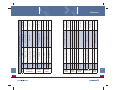
UPS15-58(1), 26-99(2), 43-44(3)
3-speed SuperBrute
UPS26-150(1), 43-100(2), 50-60(3)
3-speed SuperBruteXL
– for heating systems
– for heating systems
Technical data
Flow range:
Head range:
Motor Hp, watts:
Voltage:
Fluid temperature range:
Max. working pressure:
Flange to flange length:
Pump housing:
Pump connection type:
• Standard features:
Technical data
Flow Range:
Head Range:
Motor:
Voltage:
Fluid Temperature Range:
Max. Working Pressure:
Flange to Flange Length:
Pump Housing:
Pump Connection Type:
0 - 64 GPM
0 - 30 feet
1/25 Hp(1), 1/6 Hp(2,3)
1 x 115V (1,2,3), 230V (2,3)
36°F (2°C) to 230°F (110°C)
145 PSI
6-1/2 inches(1,2), 8-1/2 inches(3)
Cast iron(1,2,3), bronze(2,3)
(2) 1/2” dia. bolt holes (GF 15/26)
(2) 1/2” dia. bolt holes (GF 40/43)
0 - 120
0 - 47
1/3 Hp
1 x 115, 230V
36F (2C) to 230F (110C)
150 PSI
6-1/2(1), 8-1/2 inches(2,3)
Cast iron, Stainless steel
(2) 1/2” dia. bolt holes (GF 15/26)(1,2)
(2) 1/2” dia. bolt holes (GF 40/43)(2)
(4) 1/2” dia. bolt holes (GF 50)(3)
Removable check valve
• Standard features:
Run light
5
5
Performance curves
UPS15-58
UPS43-44
25
45
20
35
UPS43-100
UPS50-60
40
15
10
30
25
20
15
5
10
5
0
0
57
UPS26-150
50
Head (ft.)
Head (ft.)
30
Performance curves
UPS26-99
5
0
10 15 20 25 30 35 40 45 50 55 60 65
Flow (gpm)
0
50
10
20
30
40
50
60
70
Flow (gpm)
80
90
100 110 120
58
Pump selection
UP15-42FC, BUC5/7 MR
UP15-42(1), 26-64(2), 26-96(3) F VS
– Miximizer
Mixing reset control
Variable speed
– Variable speed
Technical data
Flow range:
Head range:
Motor Hp, watts:
Voltage:
Fluid temperature range:
Max. working pressure:
Flange to flange length:
Pump housing:
Connection type:
UP15-42FC
UP15-42BUC5
UP15-42BUC7
1 - 15.5 GPM
1 - 15 feet
1/25Hp, 85W
1 x 115V
36°F (2°C) to 205°F (96°C)
145 PSI
6-1/2 inches
Cast iron
(2) 1/2” dia. bolt holes (GF 15/26)
1/2-inch sweat
3/4-inch sweat
• Standard features:
Removable check valve
Two water temperature sensors
One outdoor temperature sensor
Boiler ON/OFF output
Line cord
5
Performance curves
UP15-42 BUC5
5
Performance curves
32
14
28
12
24
10
20
6
Boiler ON/OFF output
Manual % speed control
Voltage: 0-10 DC or 2-10 V(DC)
Current: 0-20 mA or 4-20 mA
Line cord
Signal:
16
UP15-42
UP26-64
UP26-96
16
12
4
8
2
4
0
0
0
59
• Standard features:
UP15-42 BUC7
8
4 - 35 GPM
4 - 30 feet
1/25(1), 1/12(2), 1/6(3) Hp
1 x 115V
36°F (2°C) to 205°F (96°C)(1),
to 195°F (91°C)(2,3)
145 PSI
6-1/2 inches
Cast iron
(2) 1/2” dia. bolt holes (GF 15/26)
Max. working pressure:
Flange to flange length:
Pump housing:
Connection type:
Head (ft.)
Head (ft.)
UP15-42 FC
Technical data
Flow range:
Head range:
Motor Hp:
Voltage:
Fluid temperature range:
2
4
6
8
Flow (gpm)
10
12
14
16
0
4
8
12
16
20
Flow (gpm)
24
28
32
36
60
Pump selection
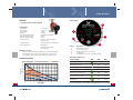
ALPHA™
Control display
– 3-speed and variable speed
Technical data
Flow Range:
Head Range:
Motor watts:
Voltage:
Fluid Temperature Range:
Max. Working Pressure:
Flange to Flange Length:
Pump Housing:
0 - 22 GPM
0 - 19 Feet
5-45W
1 x 115V
36F (2C) to 230F (110C)
150 PSI
6-1/2”
Cast iron, Cast iron rotated,
Stainless steel
GF 15/26, (2) 1/2” Dia. Bolt Holes
Connection Type:
Standard Features:
5
1
2
3
5
4
LED display
Removable check valve
Line cord plug
AUTOADAPT ™ Feature
This function controls pump performance automatically within
defined performance range. Ensuring lowest possible energy
consumption, while maintaining maximum comfort levels.
Position
1
2
3
4
5
Description
Watt or flow indicator
Three fixed speeds
Three constant pressure settings
AUTOADAPT™
Push-button for selection of pump settings
5
Approximate power usage
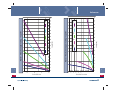
Performance curves
Head (ft.)
3 Fixed Speeds
AUTOADAPT ™
20
18
16
14
12
10
8
6
4
2
0
0
61
Speed setting
3 Constant Pressures
2
4
6
8
10 12 14
Flow (gpm)
16
18
20
Min.
Max.
High fixed speed
LED
39W
45W
Medium fixed speed
15W
30W
Low fixed speed
5W
8W
Low constant pressure
8W
45W
Medium constant pressure
14W
45W
High constant pressure
22W
45W
AUTOADAPT™
5W
45W
22
See UP Product Guide or visit www.poweredby.grundfos.com for details.
62
Pump selection
MAGNA
40-120(1), 65-60(2), 65-120(3)
Standard control features
• AUTOADAPT™
• Constant Curve
• Constant Pressure
• Proportional Pressure
• Night set back
– Variable Speed Pumps
Technical data
Flow Range:
Head Range:
Motor Hp:
Voltage:
Fluid Temperature Range:
Max. Working Pressure:
Pump Housing:
Connection Options:
5
Optional communications features
GENI Module
• Max. curve
• Min. curve
• 0-10 V analog input
• Parallel pumping
LonTalk®
10-170GPM
1-42 Feet
1/3(1,2) to 1(3) HP
1x230V
59°F to 230°F
145 PSI
Cast iron, Stainless steel
2-bolt (GF15/26)(1)
2-bolt (GF40/43)(1)
4-bolt 2”, 2.5”, 3” (GF53) (2,3)
Magna 65-120
Magna 65-60
Head (ft.)
45
40
Control
Modes
5
Permanent Magnet Motor Design
The permanent magnet rotor is designed to create greater energy savings than any other speed controlled circulator on the market.
35
30
25
20
15
10
5
0
0
63
Indicates
Flow
AUTOADAPT ™
AUTOADAPT™ is an automatic control mode designed for heating applications and is unique to the Grundfos MAGNA and ALPHA™. AUTOADAPT™
not only adjusts the pumps performance along the set control curve, but
it can also actually optimize the control curve for the particular system.
While ensuring comfort, this automatic adaptive control can reduce
energy consumption compared to traditional circulators by more than
70%.
Performance curves
Magna 40-120
Indicates
Head
20
40
60
80 100 120
Flow (gpm)
140
160
180
See product guide or visit www.grundfos.com/magna for details.
64
Pump selection
VersaFlo UP
VersaFlo UPS
– Single speed
– 3-speed
UP43-70 (1)
UP43-110 (2)
UP53-45 (3)
UP53-46 (4)
Technical data
Flow range:
Head range:
Motor Hp:
Voltage:
Fluid temperature range:
Max. working pressure:
Flange to flange length:
13 - 97 GPM
18 - 35 feet
1/2(1,3), 3/4(2,4) HP
1 x 115/230V
32°F (0°C) to 230°F (110°C)
175 PSI
8.5-inch (1,2)
10-inch (3,4)
Pump housing:
Cast iron (1,2)
Silicon bronze (3,4)
Technical data
Flow range:
Head range:
Motor Hp:
Voltage:
2-speed models
Fluid temperature range:
Max. working pressure:
Pump housing:
Connection type:
Connection types:
1.5-inch, 2-bolt (GF40/43) (1,2)
2”, 2.5”, 3” Non-ANSI (4 bolt) (3,4)
5
Connection to VFD:
Optional features:
9 - 245 GPM
1 - 59 feet
1/3 to 3 Hp
1 x 115/230V
3 x 208-230V, 460V, 575V
460V, 575V
32°F (0°C) to 248°F (120°C)
175 PSI
Cast iron, Silicon bronze
Oval flange 1-1/4 inch
Oval flange 1-1/2 inch
2”, 2.5”, 3” Non-ANSI
3” or 4” ANSI
All 3-phase units are suitable
Relay or protection module
5
• Consult VersaFlo product guide for specific performance curves
Performance curves
UP43-70
Performance curves
UP43-110
UP53-46
UP53-45
40
70
60
50
Head (ft.)
Head (ft.)
30
20
40
30
20
10
10
0
0
0
65
25
50
Flow (gpm)
75
100
0
50
100
150
Flow (gpm)
200
250
66
Pump selection
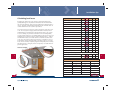
Dielectric Isolation Valves
Pump Zone Controls
UPZC-1
UPZC-3
UPZC-4/6
Technical data
Pump Connection
Pipe Connection
NPT
(inch)
GF 15/26
Bronze
1/2
591202
3/4
591203
1
591204
1/1/4
591205
1-1/2
5
Rotating flange
Wrench
boss
Dielectric sleeve
67
Solder
(inch)
Material
Numbers
591206
1/2
591207
3/4
591208
1
591209
1-1/4
591210
1-1/2
591211
Technical data
Max Number of Zones:
Priority Options:
Transformer Voltage:
Input Power 50/60HZ:
Min./Max. Ambient Temp.:
Wiring Options:
Features
1, 3, 4/6-Zones
Models UPZC-3, 4/6
No priority
Zone 1 priority
Zone 1 w/freeze protection
Freeze protection
120VAC, 24V, 15VA
1 x 120VAC +/-10%
32°F(0°C) / 104°F(40°C)
2 or 3-wire thermostats
X-X, ZC-ZR terminals
LED external diagnostics
Powder coated cover
Socketed relays (one size all
models)
5
• Full port shut-off ball valve
• Dielectric isolation = no
galvanic (dissimilar metal)
corrosion
• Service pump without
draining system
• Swivel flange allows
optimum pump
mounting position
• All hardware included
68
Installation tips
Eliminating air – purging, bleeding, & quiet comfort
Water contains dissolved gasses. Cold water contains more dissolved
gasses than hot water. When filling a hydronic system for the first
time, proper procedures must be followed to manage air elimination.
The most important requirement is to purge all free air from the
hydronic system. Elimination of free air ensures quiet operation, protects system components and provides proper transfer of heat-energy.
By raising the system pressure during purging, air bubbles trapped in
upper floor loops are re-absorbed and carried down to the purge location . The sudden discharge of water through the purge valve creates
rapid flow that forces trapped air within the system to be expelled.
• Zoning with circulators, utilizing isolation valves and a purge
fitting, will allow for fast elimination of air in primary, secondary,
and tertiary piping
• Radiant loops are easily purged if you use valved manifolds to
purge one loop at a time
• Standing cast iron radiators will have individual vents for purging
air prior to starting the system
69
• Devices, such as air-scoops or micro-bubble scrubbers are very
effective at removing dissolved air – if installed correctly!
• Gravity float-vents are typically located where air collects and will
automatically allow gasses to pass out of the hydronic system
• Unchecked air trapped in hydronic systems can accelerate
corrosion, damage components, create system noise, and lead to
no-heat calls
Straight pipe distance
can be less than 18-inches
{
6
{
18-inches minimum or 18 pipe diameters
of straight pipe before air-scoop
Once free air is eliminated and the first heating cycles begin, dissolved
gasses will come out of solution and create problems – unless you’ve
planned for eliminating air on an ongoing basis. The best location for
air elimination devices is immediately after the heat source: that’s
where the majority of air will be forced out of solution.
6
70
Installation tips
Pump installation
Thermal expansion tank sizing
•
Always point the cable entry downwards to prevent water from
entering the terminal box
•
Wet-rotor pumps must always be mounted with the shaft in a
horizontal position
•
Before starting the pump, flush clean water through the system to
remove all foreign material
Water expands when it’s heated. The level of expansion (in volume) is tied
directly to system volume in gallons, the starting and ending temperatures or
∆T, static pressure, and expansion tank volume. If you adjust the air pressure
in the thermal expansion tank so that it matches the system static pressure,
the calculations are easy to master. We’ll use Boyle’s Law, which states that
P1 x V1 = P2 x V2 ( P = pressure and V = volume). P1 x V1 = Constant Value.
P2 x V2 must equal the Constant Value.
•
Never start the pump before the system is filled with water and
properly vented. Even short periods of dry-running can damage
the pump
•
The pump inlet should be placed as close as possible to the
expansion tank (pumping away)
•
Make sure it will be possible to vent the pump and the pipe
system when making the installation. Follow proper piping
procedures when installing venting components
•
Never install a larger pump than necessary; pump noise in the
system can result
•
6
Do not install a circulator pump with aquastat too close to water
heaters or storage tanks. Heat transfer may affect the aquastat
operation
p
Total system volume is 50 gallons
P1 = 12 PSI
V1 = 4.5 gal.
P2 = ??
V2 = 3.193 gal.
Water is being heated from 70° F to 180° F
Determine final system pressure – example calculation:
Step 1: Determine the constant value
• V1 = 4.5 gal.
• P1 = 12 PSI
• 4.5 x 12 = 54 Constant Value
6
Step 2: Calculate thermal expansion for V2
• System volume = 50 gal.
• Determine ∆T (finish 180°F – start 70°F) = 110°F
• Expansion multiplier = .02614 (expansion table for water)
• 50 gal. x .02614 = 1.307 gal. of thermal expansion
• V2 = 4.5 (V1) – 1.307 = 3.193 gal.
71
Step 3: Determine P2 for final system pressure
• P2 x V2 must equal 54
• 54 ÷ 3.193 (V2) = 16.91 PSI
• 16.91 x 3.193 = 54
72
Installation tips
Determining system volume
Sizing water heaters – tank and tankless
Total system volume ??
Step 1: Determine percentage of hot water in flow
*
(Desired bathing temperature – cold water temperature )
*
(Hot water temperature – cold water temperature )
=
(110° F – 40° F) ÷ (140° F – 40° F) = .7 (70%)
* Must be coldest inlet temperature seen during the year
P1 = 16 PSI
V1 = 4.5 gal.
P2 = 28 PSI
V2 = ??
Water is being heated from 70° F to 180° F
You find the pressure in a hydronic system is higher than you’d like. Let’s say it
rises to 28 PSI, which is too close to the relief valve’s 30-lb limit. You’d like the
final pressure to be less than 20 lbs, but you’re not sure which size thermal
expansion tank will be the best fit. (This same formula can be used for potable
water thermal expansion by substituting pressure and relief values).
System fluid volume calculation example:
6
Step 1: Identify total system volume
• 16 PSI x 4.5 gal. = 72 (constant value)
• 72 ÷ 28 PSI = 2.57 gal. (V2) tank volume
• 4.5 gal - 2.57 gal. = 1.93-gallons of thermal expansion
• Determine ∆T (finish 180° F - start 70° F) = 110°
• Expansion multiplier = .02614 (from thermal expansion table)
Total System Volume 1.93 gal. ÷ .02614 = 73.73 gal.
Let’s move up to a 10-gallon thermal expansion tank, pumped up to 16 PSI.
• 16 PSI x 10 gal. = 160, our new constant value
• V2 = 10 gal. – 1.93 gal = 8.07 gal.
• P2 x 8.07 gal. = 160
• 160 ÷ 8.07 gal. = 19.83 PSI, which is exactly what you wanted
73
Step 2: Hot water required
• Measure GPM flow rate of desired bathing temperature
(Use bucket and time fill rate)
• Example: 3 GPM x .7 = 2.1 GPM of hot water
2.1 GPM x 30 minutes = 63 gal. of hot water required
Step 3: Energy required per gallon of hot water
• A gallon of water weighs 8.33 lbs. and it takes 1 BTU to raise 1 lb. of
water 1° F.
• ∆T = 100° F x 8.33 lbs./gal. = 833 BTU/gal. required net input
Step 4: Determine water heater size requirements
Tankless:
• 2.1 GPM x 833 BTU/gal. = 1,749.3 BTU/min. or 104,958 net BTU/hr.
input
• Net input = gross input x operating efficiency
• The net input must meet or exceed 104,958 BTU/hr. in this case
6
Storage tank:
• Assume 50 gallons/40,000 BTU gross input @ 82% operating
efficiency 40,000 BTU x .82 =32,800 BTU net input.
• 32,800 BTU ÷ 833 BTU/gal. = 39.4 GPH recovery rate
• 39.4 GPH ÷ 60 minutes = .657 GPM
• 30-minute run-time = 19.7 gal. recovery
• Turbulent mixing of cold with hot water in the tank will reduce
the available storage from 50 gallons to about 44 gallons
• Add 19.7 gal. to 44 gal. and you’ll have a net available hot water
draw of 63.7 gallons for a 30-minute draw
74
Installation tips
Calculating heat losses
Energy moves from hot to cold – always. The ∆T determines how
quickly that happens. Any materials in-between the ∆T will slow the
rate of energy transfer. A few easy steps will help you build a heat loss
survey – the rock-solid foundation from which you can build castles of
comfort that will exceed customer expectations.
You need to measure each room’s surface area that is exposed to colder air. The net square footage (subtract windows and doors) is then
multiplied by a factor that represents the BTU energy loss per square
foot. For example, if you want to maintain 70°F in 0°F temperature,
use the column under “70.” Insert that number in the “factor” box and
multiply your net square footage to obtain the BTU heat loss. Add up
all of the BTU heat losses in that column to obtain the total for that
room. You can use this room-by-room heat loss calculation to choose
heat emitters and/or determine why an existing room over- or underheats. There are many computer programs that quickly and accurately
determine heat loss and gain, and are accepted by code authorities for
permit applications.
Heat loss example:
Design ∆T for location
80
70
60
50
40
Window - single pane
138
121
104
86
69
Window – double pane
92
81
69
58
46
Frame wall no insulation
32
21
17
15
12
Frame wall R-11
7
5.8
4.8
4.6
3.5
Frame wall R-19
3.7
3.2
2.8
2.3
1.8
Ceiling no insulation
55
48
41
35
28
Ceiling R-11
7.5
7
5.8
4.5
3.5
Ceiling R-19
4.6
4.4
3.5
2.3
2.1
Ceiling R-30
3
2.5
2.2
1.8
1.3
Ceiling R-38
2.1
1.8
1.6
1.3
1.1
Floor R-11
6.6
5.8
4.9
4.1
3.2
Floor R-19
4.1
3.7
3.1
2.6
2
Door – wood solid core
37
32
28
23
18
Door – insulated core
38
33
28
24
19
Door – glass single pane
92
81
69
58
46
Door – glass double pane
58
51
44
36
29
Slab – No edge insulation
64.8
56.7
48.6
40.5
32.4
Slab – 2-inch edge insulation
16.8
14.7
12.6
10.5
8.4
Slab heat loss per linear foot exposed
6
6
Square foot x factor = BTU loss
Sq. ft.
Factor
BTUs
Window
Item
12
81
972
Door
21
32
672
Net wall
47
3.2
150.4
Ceiling
120
1.8
216
100
14.7
Floor
Slab: exp. feet
75
Total BTUs for room
1,470
3,480.4
76
Installation tips
Outdoor reset
Pipe sizing
Heat loss is directly affected by outdoor air temperatures: the colder
the outdoor temperature, the greater the heat loss. Non-modulating
boilers run until the thermostat is satisfied; the burner is turned on
and off by the aquastat. This wastes energy by overheating the water
during most of the heating season. Outdoor sensor monitors the
outdoor air temperature and may also include sensors to monitor
return water temperature to prevent sustained flue gas condensation
within the boiler and/or cold-shocking cast iron boilers. More
advanced outdoor reset controls monitor outdoor, supply, and return
water temperatures and even the amount of fuel that should be
burned.
The flow rate required is determined by how many BTUs must be
transported and the ∆T of the supply/return. If we use a 20° F ∆T, the
transfer rate will be 10,000 BTUs per each GPM of flow. Water weighs
8.34 lbs. per gallon and it takes one BTU to raise 1 lb. of water 1° F. 8.34
x 60 (minutes for 1 GPM) x 20 (∆T) = 10,008 BTUs. Rounding down to
10,000 makes it easy to calculate flow rates. If the heat source has a
net output of 100,000 BTUs, the flow rate needs to be 10 GPM at 20°
∆T.
You can quickly match tubing sizes to required BTU loads. The maximum fluid velocity should be no more than 4 feet per second to avoid
velocity noise and or erosion corrosion . The following charts show
GPM flow rates for each pipe size.
To use outdoor reset control properly, you need to know four things:
1.
2.
3.
4.
Maximum supply-water temperature (MT)
Lowest supply-water temperature (LT)
Indoor supply-water ∆T (= MT – LT)
Outdoor temperature ∆T (= 68°F – coldest air temperature)
This chart is for copper tubing. If you need 15,000 BTUs delivered, then
½” copper (nominal pipe size) would be a perfect match.
Pipe
Size
The reset ratio = (MT – 68) ÷ (68 – coldest outdoor air temperature)
Max.
GPM
Example: 180°F MT; 68°F LT; Designed for 10°F outdoor air
Reset ratio = (180 – 68) ÷ (68 – 10) = 112 ÷ 58 = 1.9
For every 1°F drop in outdoor air temperature, the supply water
temperature will be increased 1.9°F (starting at 68°F).
1/2” 3/4”
3.2
6.5
1”
1¼”
1½”
2”
10.9 16.3 22.9 39.6
2½”
3”
75
120
The following flow chart is for PEX tubing.
6
Pipe
Size
Supply sensor
Max.
GPM
Outdoor
sensor
3/8” 1/2” 5/8” 3/4”
1.2
2
4
6
1”
6
9.5
Reset controller
Return sensor
77
65
78
Trouble shooting
Check air / Remove air from zone
Check circulator function
No heat - One zone
Check thermostat function
Check switching relay function
Clean/adjust check valve
Check for water / Slab leaks
No heat
No heat - One radiator
Check electrical supply
Is there fuel?
Check oil or gas supply
Check for air in unit / Purge coil
What is the boiler pressure?
Check if PRV is functioning
Is circulator functioning?
Check power, flow
What is the boiler
temperature?
Check aquastat function
Is there air in the
boiler?
Vent boiler / Add air eliminator
Is LWCO functioning?
Test LWCO / Replace if not functioning
Observe silica-carbide
Ignitor
No visible glow - if voltage present,
replace ignitor
Flame sensor fault
code
Clean sensor and electrical contacts
or replace
Is thermostat calling
for heat?
Test thermostat function, wire
Is flame relay in lockout?
Check burner function
Is pilot light on?
Relight pilot / Test thermal couple
Is gas burner flame
small?
Check gas pressure with manometer
∆T @ coil
Check for air, flow, ∆T
Check mixing valve function,
temperature
Check injection control and circulator
Check radiator for air
Low heat
7
Check radiator for restricted air flow
Check radiator piping
Check length of baseboard & piping
Not enough heat Baseboard
Check if vent louver is open
Check for blocked air flow
Monoflow system / Check distance
between tees
79
66
67
No heat
Check reverse aquastat function
Not enough heat - One
radiator
Install thermostatic radiator valve
Is there power?
Check flow / Check zone valve
No heat - Radiant zone
Too much heat
Check distance between tees on
main
Check temperature of water?
No heat - Air handler
Throttle radiator valve
Close baseboard louver
No air, look for flow problem/open
radiator valve
Hot Water Boilers
Hot Water Systems
Bleed radiator
Check thermostat function
High heat
Look for air - if none, raise pressure
Hot Water Systems
No heat - Upper floors
7
80
Trouble shooting
3-piece circulator / Oil bearing
assembly
Check power supply (Voltage)
Check for air / Install air eliminator
Check system pressure
Check for good, clean neutral
Air scoop not installed correctly, requires 18 pipe diameters of straight
piping before entering air scoop
Circulators
Purge system
Is air scoop installed properly?
Install wet rotor circulator
Power head mounted in wrong
position
Performance
Check function of flow valve
Check system temperature / Limit
function
Noise
Circulators
Squealing
Is direction of flow correct?
No heat / Low heat
Check that all valves on zone are
open
Check for proper sizing of circulator
Check proper speed if circulator is
variable
Replace circulator if not functioning
Replace circulator coupler
Rattling / Banging /
Grinding
Check operation of flow valve
Misaligned motor mount / Replace
motor
Too much heat
Worn bearing assembly or impeller
/ Replace
81
Replace bearing assembly or
circulator
Copper adapter
Replace or repair fitting
Flange thread
Replace adaptor, nipple, or flange
Bleed baseboard / Purge zone
68
69
Check that valve is open
No heat / Low heat
Cast Iron
Bearing assembly
Baseboard Heating
Leaking
7
Replace flange gasket / Flanges if
needed
IFC Model - Clean or replace checkvalve
Check limit control function /
On/Off contact / Replace if needed
Replace circulator with wet rotor
model
From flanges
IFC Model - Remove / Clean /
Replace valve
Check for air flow disruption
Increase system temperature
7
Add more baseboard
Zone system
Overheating
Check thermostat operation/
Replace if needed
Re-pipe system using reverse-return
method
82
Trouble shooting
Check system pressure
Open louvers
Check PVR function
Boiler Relief
Remove carpeting to increase air
flow
Open / adjust old-style check valve
Move drapes or furniture away from
baseboard
Check if expansion tank is full Drain / could be non-bladder tank
Leaking
Check expansion tank sizing
Clean debris and pet hair from fins
Check relief valve spring / Replace
valve
Purge air from zone / Test for slab
leak
Check water pressure/ Install PRV
T & P Valves
Add more baseboard
Check Circulator function / Replace
if needed
Valves
Check thermostat function / Replace if needed
Close louvers
Remove some of the fin
Zone system
Overheating
Check thermostat operation /
Replace if needed
Check cold water line for check
valve
Leaking
Check water temperature / Test
aquastat
Check zone valve function
No heat
Check circulator function
Check reverse aquastat function
Check thermostat function
Decrease system temperature
Check for power, voltage
Radiator
Valve
Install outdoor reset control
Check flow valve operation
Check for system or slab leak
Thermostatic
Radiator Valve
7
83
Thermal expansion / Install Thermal expansion tank
Check location of circulator
Three Way
Increase system temperature
Fin-Tube
Baseboard Heating
No heat / Low heat
Check expansion tank diaphragm /
Change tank
70
71
Check to see if valve is open
No heat - One
radiator
Check for valve obstruction
7
Check operation of actuator
Check for valve operation
No heat - One
radiator
Check for valve obstruction
84
Trouble shooting
Check Upper / Lower aquastat
function
Test / Replace Thermal couple
Vent spill switch tripped - reset/replace
Gas
Check aquastat / gas valve operation / Vapor safe limit
Check aquastat well, calcium build
- up / Replace
Water Heaters
Not enough hot water
Cracked electrode ceramic - replace
Clean, tune up
Radiators
Check oil primary control operation
/ Replace
Oil
Not enough hot water
Survey hot water load / Install larger
heater
Raise temperature / Install ASSE
1016/1017 mixing valve
Bleed air
Check aquastat operation / Replace
if needed
Check oil supply, oil pump operation
Check aquastat well for calcium
build - up / Replace
Not enough hot water
Check electrical supply, circuit
breaker
Test element operation / Replace
if needed
Survey hot water load / Install larger
heater
Raise temperature / Install mixing
valve
No hot water
No hot water
Survey hot water load / Install larger
heater
Raise temperature / Install mixing
valve
7
Panel Recessed Freestanding Convectors
No hot water
Electric
Water Heaters
Check / Relight pilot
Check that valve is open
Check radiator / system piping
No air, then look at flow problem
No heat / Low Heat
Check circulator operation / sizing
Check radiator sizing
Disassemble, check radiator valve
for broken stem
Increase system temperature
Zone system
Install thermostatic radiator valve
Over heating
Check thermostat operation /
Replace if needed
Re-pipe system using reverse-return
method
7
Decrease system temperature
85
72
73
86
Trouble shooting
Check ΔT / Slow down flow of
system
Performance
System
Expansion
Check sizing of expansion tank
Align friction glides on brackets
Pipe penetrations at walls must be
oversized
Baseboard radiation
Check for correct sizing for BTU
output
Low heat
Check that system piping is correct
Long runs must have expansion
compensators
Is fluid velocity too high?
Element must have play and not be
too rigid
Erosion / Noise
Oversize penetration openings in
walls and floors
Pex tubing
Staples or J-hooks too tight
Corrosion
Is there a bad ground wire on water
main?
Proper air eliminator to remove
micro bubbles
Is pipe supported correctly?
Are pipe hangers too tight?
Purge into bucket to see micro
bubbles
Expansion and
contraction
Raise system fill pressure when
purging
7
Does piping rub against any wood?
Is there room for the copper to
expand?
Flow meters always on supply
manifolds
Radiant manifolds
Is PH of the system fluid too high
or low?
Is the electrical system grounded
correctly?
Leaking
End loops must be large / mushroom heads
Injection pumping minimizes noise
and expansion
Radiant
Are there any dissimilar metals
connected?
Piping
Noises
Must not touch each other / Space
properly
Air in tubing
Is flow restricted at inlet of circulator?
Is system fluid dirty or full of debris?
Allow for tubing to expand
Extruded aluminum
plates
Check for flow restrictions
7
Clean joint thoroughly and re-solder
Valves or actuators always on return
manifolds
Solder joints
Circulator too large
Replace copper pipe and fitting and
re-solder
Check by-pass valves
87
74
75
88
Trouble shooting
References
Drawing symbols
Air in System or Noise
Air
Install air eliminator
+RW:D
Hot
water piping
No heat - Air bound
Air scoops need 18 pipe diameters of
straight pipe before entering scoop
&ROG:
Cold
water piping
Check autovent / Replace if needed
3XUJLQ
Hose
bib / boiler drain
Bleed radiators or purge zones
Globe
valve
*OREH
Remove air scoop, install micro
bubble design
Pressure
3UHVVX reducing valve
Horizontal tube
+R
radiator
+RVH%
Hose
bib / boiler drain
3UHVVX relief valve
Pressure
0
Check system fill pressure
Radiant panel circuit
w/zone valves
3-way
motorized mixing valve
:D\
3-way
thermostatic valve
:D\
Check relief valve
Radiant panel circuit
Condensing boiler
Outdoor Reset Control
Zone
valve 2-way
=RQH9
Test outdoor sensor
Diverter
'LYHUWHtee
P/S36)LW
fitting
Test supply/mix sensor
Gas fired boiler
%DFNIOR
Backfl
ow preventer
Test reset control function
6WUDLQH
Strainer
Check reset control perimeters
)ORDW7
Float
type air vent
Sensor placed next to heated
ventilation
Air $LU6H
separator
No heat
Oil fired boiler
&DVW,U
Cast
iron air scoop
Sensor placed in direct sun light,
place on north facing wall
Circulator
&LUFXOD w/isolation flanges
Check boiler command
Circulator
&LUFXOD w/integral flow check
Recirculation
Solar collector array
7
Install recirculation line, install
UP10-16B
'LDSKU
Diaphram-type
expansion tank
Install Comfort System
+HDW(
Heat
exchanger
Long wait for hot water at tap
Check valve operation
Fin tube baseboard
8
Properly sized circulator
&DVW
Cast iron radiator
89
76
77
Gas fired
water heater
Indirect
DHW tank
90
References
Abbreviations used in heating
Equivalent value in different units
British Thermal Unit
BTU
Gallons per minute
GPM
British Thermal Unit
per hour
BTUh
Gallons per hour
GPH
Cubic centimeter
cc
Ounce
oz
Cubic foot
cu ft
Pound
lb
Cubic feet per min.
cfm
Pounds per square inch
psi
Cubic feet per sec.
cfs
Pounds per square inch, gauge
psig
cu in
Pounds per square IN, absolute
psia
deg or °
Revolutions per min.
rpm
Degree, Celsius
°C
Revolutions per sec.
rps
Degree, Fahrenheit
°F
Second
sec
746 W
1 hp
=
0.746 kW
33,000 ft-lb per minute
550 ft-lb per second
1 hp
=
33.475 BTUh
34.5 lbs of steam/hr from and at 212°F
1,000 W
Cubic inches
Degree
1 kW
1.34 hp
3.53 lbs water evaporated per hour from
and at 212°F
1W
=
0.00134 hp
0.0035 lb of water evaporated per hour
1,000 Whr
Diameter
diam
Specific gravity
sp gr
Direct-current
d-c
Specific heat
sp ht
Feet per min.
fpm
Square foot
sq ft
3.53 lbs water evaporated from and at 212°F
Feet per sec.
fps
Square inch
sq in
22.75 lbs of water raised from 62°F to 212°F
Foot
Foot-pound
ft
Volt
V
ft-lb
Watt
W
1.34 hp/hr
1 kwhr
8
Freezing point
91
=
Watt hour
Whr
Watt min.
Wmin
fp
78
79
=
1 Joule
=
MJ
(Megajoule)
=
3,600,000 joules
1 watt second
0.000000278 kWhr
1,000,000 Joule = 948 BTU
8
239 kcal
92
References
Equivalents of electrical units
1 kW
=
Conversion factors
1.34 hp
Water
0.955 BTUs
U.S. Gallons
x
8.34
=
Pounds
U.S. Gallons
x
0.13368
=
Cubic Feet
U.S. Gallons
x
231
=
Cubic Inches
42.746 BTUm
U.S. Gallons
x
3.78
=
Liters
2564.76 BTUh
Imperial Gallons
x
277.3 Cubic Inches
17.452 Wmin
Imperial Gallons
at 62°F
=
10.0 Pounds
Cubic In. of
Water (39.2°)
x
0.03613
=
Pounds
Cubic In. of
Water (39.2°)
x
0.004329
=
U.S. Gallons
Cubic In. of
Water (39.2°)
x
0.576384
=
Ounces
Cubic Feet of
Water (39.2°)
x
62.427
=
Pounds
Cubic Feet of
Water (39.2°)
x
7.48
=
U.S. Gallons
Cubic Feet of
Water (39.2°)
x
0.028
=
Tons
Pounds of Water
x
27.72
=
Cubic Inches
Pounds of Water
x
0.01602
=
Cubic Feet
Pounds of Water
x
0.12
=
U.S. Gallons
57.3 BTUm
3438 BTUh
746 W
1 hp
1 BTU
=
=
0.2909 Whr
8
93
80
81
8
94
References
Converting PSI to Head (ft.)
Pressure
144 Pounds Per Square Foot
170
2.0355 Inches of Mercury at 32°F.
1 Pound Per Square Inch
=
70
2.0416 Inches of Mercury at 62°F.
2.31 Feet of Water at 62°F.
160
150
27.71 Inches of Water at 62°F
=
Pressure in Pounds per square inch (PSI)
1 Ounce Per Square Inch
60
0.1276 Inches of Mercury at 62°F.
1.732 Inches of Water at 62°F.
2116.3 Pounds Per Square Foot
33.947 Feet of Water at 62°F.
30 Inches of Mercury at 62°F.
1 Atmosphere
(14.7 Lbs. Per Sq. In.)
=
29.922 Inches of Mercury at 32°F.
760 Millimeters of Mercury at 32°F.
101.3 kilopascal
235.1 Ounces Per Square Inch
0.03609 Pounds Per Square Inch
0.5774 Ounce Per Square Inch
1 Inch Water (at 62°F.)
=
5.196 Pounds per Square Foot
0.248 kilopascal
235.1 Ounces Per Square Inch
1 Foot Water (at 62°F.)
=
1 Inch Mercury (at 62°F.)
=
120
50
110
100
40
80
30
1.132 Feet Water at 62°F.
70
60
50
20
62.355 Pounds Per Square Foot
7.86 Ounces Per Square Inch
90
40
30
10
20
8
10
13.58 Inches Water at 62°F.
95
130
0.433 Pounds Per Square Inch
0.491 Pounds Per Square Inch
8
140
Head of Water in feet (ft.)
6.895 kilopascal
0
82
81
8
0
96
References
Water Pressure to Feet Head
Feet Head of Water to PSI
Feet Head
Pounds Per
Square Inch
Feet Head
Pounds Per
Square Inch
1
0.43
100
43.31
Pounds Per
Square Inch
Feet Head
1
2.31
100
230.90
2
4.62
110
253.98
0.87
110
47.64
3
1.30
120
51.97
3
6.93
120
277.07
9.24
130
300.16
11.54
140
323.25
4
1.73
130
56.30
4
5
2.17
140
60.63
5
6
2.60
150
64.96
6
13.85
150
346.34
7
16.16
160
369.43
392.52
7
3.03
160
69.29
8
3.46
170
73.63
8
18.47
170
77.96
9
20.78
180
415.61
10
23.09
200
461.78
3.90
180
10
4.33
200
86.62
15
6.50
250
108.27
15
34.63
250
577.24
129.93
20
46.18
300
692.69
808.13
20
8.66
300
25
10.83
350
151.58
25
57.72
350
30
12.99
400
173.24
30
69.27
400
922.58
40
92.36
500
1154.48
40
17.32
500
216.55
50
21.65
600
259.85
50
115.45
600
1385.39
138.54
700
1616.30
800
1847.20
60
25.99
700
303.16
60
70
30.32
800
346.47
70
161.63
80
34.65
900
389.78
80
184.72
900
2078.10
433.00
90
207.81
1000
2309.00
90
38.98
1000
NOTE: One foot of water at 60°F equals .433 pounds pressure per square inch.
97
Pounds Per
Square Inch
2
9
8
Feet Head
NOTE: One pound of pressure per square inch of water equals 2.31 feet of water
at 60°F.
To find the pressure per square inch for any feet head not given in this table
above, multiply the feet head by .433.
Therefore, to find the feet head of water for any pressure not given in this
table above, multiply the pressure (pounds per square inch) by 2.31.
82
8
98
423
534
660
800
952
5
360
470
596
734
899
1057
5-1/2
73
130
201
290
396
517
655
808
978
1163
6
79
141
219
315
432
564
714
880
1066
1268
6-1/2
88
155
236
340
468
611
770
954
1156
1374
1480
7
92
165
255
368
504
658
832
1028
1244
7-1/2
99
179
278
396
540
705
889
1101
1335
1586
8
106
190
291
423
576
752
949
1175
1424
1691
9
119
212
330
476
648
846
1071
1322
1599
1903
10
132
236
366
529
720
940
1189
1463
1780
2114
12
157
282
440
634
864
1128
1428
1762
2133
2537
14
185
329
514
740
1008
1316
1666
2056
2490
2960
Example:
• 60” length x 36” width x 48” height = 103,680 cu. in.
• 103,680 ÷ 231 = 448.8 Gallons
1.65
1.00
3.02
1.84
1.00
1.00
4.25
2.50
1.25
6.39
11.70
39
68
133
273
3.89
1.50
1.00
2.12
7.12
11.90
6.50
23
13
37
19
166
81
44
90
377
205
3.87
2.70
4.50
1.82
3.06
1.00
6
324
264
5
238
181
4
165
3-1/2
107
119
3
59
66
1.67
4-1/2
1.00
846
1.00
740
712
2
623
586
2-1/2
513
475
9
416
376
6.13
329
288
3.34
252
210
2.00
184
147
1.00
129
95
1-1/2
83
53
12
46
4
9.10
3-1/2
5.25
635
3.10
534
1.50
440
1.00
357
1-1/4
282
65
216
30
158
42.50
100
20.90
71
11.40
40
23.30
3
6.82
530
14.00
445
3.45
367
6.97
298
2.25
235
4.30
180
2.05
131
1.00
91
1.00
59
1
33
3/4
423
2-1/2
140
356
96.90
14.81
294
52.90
12.24
238
31.70
9.91
188
15.80
7.83
144
10.00
5.99
105
4.88
4.41
73
2.27
3.06
47
1.00
1.96
26
1/2
1.1
4
17.62
1
2
3-1/2
72
3
66
2-1/2
60
2
54
1-1/2
48
1-1/4
42
1
36
3/4
30
1/2
24
Pipe
Size (in.)
18
Number of Smaller Pipes Equivalent to One Larger Pipe
Inside Diameter (inches)
• Measure tank (inches): Length, Width, Height
• Then multiply Length x Width x Height ÷ 231
99
5
Number of Gallons
Capacity of Rectangular Tanks in U.S. Gallons:
8
19.60
Depth
or
Length
(ft.)
6
Capacity of Round Storage Tanks
620
References
8
100
101
0.006
0.007
0.008
Gallon
per Foot
Gallon
per Foot
Gallon
per Foot
0.013
0.012
0.011
1/2
–
0.017
0.017
5/8
0.027
0.025
0.023
3/4
0.063
1-1/4
0.065
0.045
0.068
Type M
0.043
Type L
0.040
1
0.095
0.092
0.089
1-1/2
0.165
0.161
0.156
2
0.254
0.248
0.242
2-1/2
0.016
Gallon
per Foot
0.023
3/4
0.040
1
0.063
1-1/4
0.102
1-1/2
0.170
2
0.275
2-1/2
0.390
3
0.530
3-1/2
.50
Gallon(s)
.92
1/2
* Check manufacturer for specific capacities
3/8
Tubing Size (in.)
1.33
5/8
1.84
3/4
3.04
1
PEX - Approximate - Water Capacity (Gal.) / 100 Foot)*
1/2
Pipe Size
(in.)
0.690
4
5
1.100
Steel & Wrought Iron Pipe - Water Capacity Per Linear Foot
3/8
Pipe Size
(in.)
8
Type K
Copper Tubing - Water Capacity (Gal.) / Linear Foot
1.500
6
0.363
0.354
0.345
3
References
8
102
8
103
1-1/2”
1-1/4”
1”
3/4”
Nominal
Iron
Pipe Size
(inches)
730
350
190
20
890
590
285
152
30
760
500
245
130
40
79
150
305
460
84
160
320
490
90
170
350
530
70
96
180
370
560
105
195
400
610
115
215
440
670
100
90
80
120
60
50
100
150
64
120
250
380
125
72
130
275
410
Cast Iron
Brass or
Copper
Stainless
Steel
Carbon
Steel
Wrought
Iron
0.4
0.5
0.6
0.4
0.4
0.7
1.1
1.1
0.8
0.8
0.9
1.4
1.4
0.9
1
140
1.1
1.6
1.6
1.1
1.2
180
1.3
2.1
2
1.4
1.4
200
1.5
2.3
2.2
1.5
1.7
220
1.7
2.5
2.5
1.7
1.9
1100
1050
520
278
10
LENGTH OF PIPE (FEET)
(Based on 0.60 Specific Gravity, 0.30” W.C. Pressure Drop)
50
Temp.
Degrees
(F)
260
1.9
3.0
2.9
2.0
2.1
1600
1.61
1.38
1.049
0.824
Internal
Diameter
(inches)
Capacity of Pipe in Cubic Feet of Gas Per Hour
200
55
100
210
320
175
59
110
225
350
References
Linear Expansion of Pipe - Inches per 100 feet
280
2.2
3.2
3.2
2.2
2.4
300
2.4
3.5
3.4
2.4
2.6
340
2.8
3.9
3.9
2.7
2.9
8
104
References
Heat Losses From Insulated Pipe
Heat Losses From Bare Steel Pipe Based on 70°F Surrounding Air
85 Percent Magnesia Type
BTU per Linear Foot Per Hour Per °F
Difference (Surrounding Air Assumed 75°F)
Temperature of Pipe, °F
Diameter of Pipe
(inches)
100
200
150
180
210
240
Heat Loss per Lineal Foot of Pipe - BTU per Hour
1/2
13
22
40
60
82
106
3/4
15
27
50
74
100
131
1
19
34
61
90
123
160
1-1/4
23
42
75
111
152
198
1-1/2
27
48
85
126
173
224
2
33
59
104
154
212
275
2-1/2
39
70
123
184
252
327
3
46
84
148
221
303
393
3-1/2
52
95
168
250
342
444
4
59
106
187
278
381
496
Pipe Size
(inches)
8
105
1/4
4
8
14
21
3/8
6
1/2
7
5/8
3/4
29
37
10
18
13
22
28
37
48
33
45
59
8
15
26
39
53
9
17
30
45
61
Max. Temp. of Pipe Surface °F
125
175
225
275
0.160
1/2
1
0.145
0.150
0.157
3/4
1
0.165
0.172
0.177
0.180
1
0.190
0.195
0.200
0.203
1-1/2
0.160
0.165
0.167
0.170
1
0.220
0.250
0.232
0.237
1-1/2
0.182
0.870
0.193
0.197
0.260
1
1-1/4
1-1/2
Heat Losses From Bare Copper Pipe Based on 70°F Surrounding Air
Insulation
Thickness
(inches)
2
1
0.240
0.247
0.255
1-1/2
0.200
0.205
0.210
0.215
1
0.282
0.290
0.297
0.303
1-1/2
0.230
0.235
0.240
0.243
2
0.197
0.200
0.205
0.210
1
0.322
0.330
0.340
0.345
1-1/2
0.260
0.265
0.270
0.275
68
2
0.220
0.225
0.230
0.237
79
1
0.375
0.385
0.395
0.405
1-1/2
0.300
0.305
0.312
0.320
2-1/2
1
11
21
37
55
75
97
1-1/4
14
25
45
66
90
117
2
0.253
0.257
0.263
0.270
1-1/2
16
29
52
77
105
135
1
0.419
0.430
0.440
0.450
2
20
37
66
97
132
171
1-1/2
0.332
0.340
0.345
0.352
2-1/2
24
44
78
117
160
206
2
0.280
0.285
0.290
0.295
1
0.460
0.470
0.480
0.492
3
28
51
92
136
186
240
3-1/2
32
59
104
156
212
274
4
36
66
118
174
238
307
3
3-1/2
4
90
91
1-1/2
0.362
0.370
0.379
0.385
2
0.303
0.308
0.315
0.320
8
105
107
Flow Rate (GPM)
Flow Rate (GPM)
1.0
1.5
2.0
2.5
3.0
3.5
4.0
4.5
5.0
5.5
6.0
6.5
7.0
7.5
8.0
8.5
9.0
9.5
10.0
1.0
1.5
2.0
2.5
3.0
3.5
4.0
4.5
5.0
5.5
6.0
6.5
7.0
7.5
8.0
8.5
9.0
9.5
10.0
8
988
1 , 4 82
1 , 97 6
2 , 47 0
2 , 964
3 , 45 8
3 , 95 2
4, 446
4, 940
5 , 43 4
5 , 92 8
6, 42 2
6,916
7,410
7,904
8,398
8,892
9,386
9,880
494
741
988
1,235
1,482
1,729
1,976
2,223
2,470
2,717
2,964
3,211
3,458
3,705
3,952
4,199
4,446
4,693
4,940
3°
1 , 4 82
2,223
2 , 964
3 , 7 05
4, 446
5 , 1 87
5 , 92 8
6, 669
7 , 41 0
8,151
8,892
9,633
10,374
11,115
11,856
12,597
13,338
14,079
14,820
4°
5°
2 , 47 0
3 , 7 05
4, 940
6, 1 7 5
7 , 41 0
8,645
9,880
11,115
12,350
1 3 , 5 85
1 4 , 82 0
1 6, 05 5
1 7 , 2 90
1 8, 5 2 5
1 9, 7 60
2 0, 995
22, 230
2 3 , 465
2 4, 7 00
6°
2 , 964
4, 446
5 , 92 8
7 , 41 0
8,892
10,374
11,856
1 3, 338
1 4 , 82 0
1 6, 3 02
1 7 , 7 84
1 9, 2 66
2 0, 7 48
22, 230
23, 7 1 2
2 5 , 1 94
2 6, 67 6
2 8, 1 5 8
2 9, 640
HEAT OUTPUT IN (BTUH)*
1 , 97 6
2 , 964
3 , 95 2
4, 940
5 , 92 8
6, 91 6
7 , 904
8,892
9,880
10,868
11,856
12,844
1 3 , 83 2
1 4 , 82 0
1 5 , 808
1 6, 7 96
1 7 , 7 84
1 8, 7 7 2
1 9, 7 60
7°
3 , 45 8
5 , 1 87
6, 91 6
8, 645
10,374
1 2 , 1 03
1 3 , 83 2
1 5 , 5 61
1 7 , 2 90
1 9, 01 9
2 0, 7 48
2 2 , 47 7
2 4, 2 06
2 5 , 93 5
2 7 , 664
2 9, 3 93
31 , 1 22
3 2 , 85 1
3 4 , 5 80
92
93
13°
6, 42 2
9,633
1 2 , 84 4
1 6, 05 5
1 9, 2 66
2 2 , 47 7
2 5 , 688
2 8, 899
32, 1 1 0
35 , 321
3 8, 5 3 2
41 , 7 43
44, 95 4
48, 1 65
5 1 , 37 6
5 4 , 5 87
5 7 , 7 98
61 , 009
64, 2 2 0
14°
15°
7 , 41 0
1 1 ,1 1 5
1 4 , 82 0
1 8, 5 2 5
22, 230
2 5 , 93 5
2 9, 640
3 3 , 3 45
3 7 , 05 0
40, 7 5 5
44, 460
48, 1 65
5 1 , 87 0
5 5 ,5 7 5
5 9, 2 80
62 , 985
66, 690
7 0, 3 95
7 4, 1 00
16°
7 , 904
1 1 , 85 6
1 5 , 808
1 9, 7 60
23, 7 1 2
2 7 , 664
3 1 , 61 6
3 5 , 5 68
3 9, 5 2 0
43 , 47 2
47 , 42 4
5 1 , 37 6
5 5 , 328
5 9, 2 80
63 , 2 3 2
67 , 1 84
7 1 , 1 36
7 5 , 088
7 9, 040
HEAT OUTPUT IN (BTUH)*
6, 91 6
10,374
1 3 , 83 2
1 7 , 2 90
2 0, 7 48
2 4, 2 06
2 7 , 664
31 , 1 22
3 4 , 5 80
3 8, 03 8
41 , 496
44, 95 4
4 8, 4 1 2
5 1 , 87 0
5 5 , 328
5 8, 7 86
62 , 2 44
65 , 7 02
69, 1 60
* 100% Water mean temperature of 120°F
12°
5 , 92 8
8, 892
1 1 , 85 6
1 4 , 82 0
1 7 , 7 84
2 0, 7 48
23, 7 1 2
2 6, 67 6
2 9, 640
3 2 , 604
3 5 , 5 68
3 8, 5 3 2
41 , 496
44, 460
47 , 42 4
5 0, 3 88
5 3, 35 2
5 6, 3 1 6
5 9, 2 80
11°
5,434
8,151
10,868
13,585
16,302
19,019
21,736
24,453
27,170
29,887
32,604
35,321
38,038
40,755
43,472
46,189
48,906
51,623
54,340
8, 3 98
1 2 , 5 97
1 6, 7 96
2 0, 995
2 5 , 1 94
2 9, 3 93
3 3 , 5 92
3 7 , 7 91
41 , 990
46, 1 89
5 0, 3 88
5 4 , 5 87
5 8, 7 86
62 , 985
67 , 1 84
7 1 , 3 83
7 5 , 5 82
7 9, 7 81
83 , 980
17°
HEAT OUTPUT TABLE - 2 Temperature Differential (°F)
* 100% Water mean temperature of 120°F
2°
1°
HEAT OUTPUT TABLE - 1 Temperature Differential (°F)
8°
8, 892
1 3, 338
1 7 , 7 84
22, 230
2 6, 67 6
31 , 1 22
3 5 , 5 68
40, 01 4
44, 460
48, 906
5 3, 35 2
5 7 , 7 98
62 , 2 44
66, 690
7 1 , 1 36
7 5 , 5 82
80, 02 8
84 , 4 7 4
88, 92 0
18°
3 , 95 2
5 , 92 8
7 , 904
9,880
1 1 , 85 6
1 3 , 83 2
1 5 , 808
1 7 , 7 84
1 9, 7 60
21 , 7 36
23, 7 1 2
2 5 , 688
2 7 , 664
2 9, 640
3 1 , 61 6
3 3 , 5 92
3 5 , 5 68
3 7 , 5 44
3 9, 5 2 0
9°
9, 3 86
1 4, 07 9
1 8, 7 7 2
2 3 , 465
2 8, 1 5 8
3 2 , 85 1
3 7 , 5 44
42 , 2 3 7
46, 93 0
5 1 , 62 3
5 6, 3 1 6
61 , 009
65 , 7 02
7 0, 3 95
7 5 , 088
7 9, 7 81
84 , 4 7 4
89, 1 67
93 , 860
19°
4, 446
6, 669
8, 892
11,115
1 3, 338
1 5 , 5 61
1 7 , 7 84
2 0, 007
22, 230
2 4, 45 3
2 6, 67 6
2 8, 899
31 , 1 22
3 3 , 3 45
3 5 , 5 68
3 7 , 7 91
40, 01 4
42 , 2 3 7
44, 460
10°
9,880
14,820
19,760
24,700
29,640
34,580
39,520
44,460
49,400
54,340
59,280
64,220
69,160
74,100
79,040
83,980
88,920
93,860
98,800
20°
4,940
7,410
9,880
12,350
14,820
17,290
19,760
22,230
24,700
27,170
29,640
32,110
34,580
37,050
39,520
41,990
44,460
46,930
49,400
References
8
108
Velocity (ft./Sec.)
109
Head Loss (ft./100 ft.)
0
2
4
6
8
10
12
14
16
18
20
22
0.5
1
1.5
2
2.5
3
3.5
4
0
0
2
2
1
1
4
5
6
8
Flow (GPM)
7
1/2
9
10
3/4
11
3
4
5
6
8
8
Flow (GPM)
7
3/8
1/2
9
10
3/4
11
Water – Head Loss Copper Tubing – Type K
3
3/8
Water – Velocity Copper Tubing – Type K
12
1
12
1
13
13
14
1-1/4
14
1-1/4
15
15
References
8
110
Velocity (ft./Sec.)
111
4
0
0
2
4
6
8
10
12
14
16
18
0.5
1
1.5
2
2.5
3
3.5
Head Loss (ft./100 ft.)
8
0
2
2
1
1
4
5
6
7
8
Flow (GPM)
9
1/2
10
3
4
5
6
8
Flow (GPM)
7
3/8
9
1/2
10
11
3/4
12
11
3/4
Water – Head Loss Copper Tubing – Type L
3
3/8
Water – Velocity Copper Tubing – Type L
13
1
12
1
14
13
15
1-1/4
14
1-1/4
16
15
References
8
112
113
Velocity (ft./Sec.)
0
2
4
6
8
10
12
14
16
18
20
0.5
1
1.5
2
2.5
3
3.5
4
0
0
8
Head Loss (ft./100 ft.)
1
1
2
2
4
5
6
7
8
9
Flow (GPM)
1/2
10
11
12
3/4
3
4
5
6
8
Flow (GPM)
7
3/8
9
1/2
10
11
3/4
13
12
Water – Head Loss Copper Tubing – Type M
3
3/8
Water – Velocity Copper Tubing – Type M
1
14
13
1
14
15
15
1-1/4
16
1-1/4
16
17
References
8
114
115
Estimated Velocity (ft./Sec.)
0
1
2
3
4
5
6
7
8
9
10
0
0
0.5
1
1.5
2
2.5
3
3.5
4
4.5
0
8
Estimated Head Loss (PSI/100 ft.)
1
1
3
1/2
5/8
3
4
1/2
5
5/8
6
Flow (GPM)
1
Check with PEX manufacturer for specicic Head Loss figures
2
3/8
Estimated Water – Head Loss – PEX Tubing 1
4
5
6
Flow (GPM)
1
Check with PEX manufacturer for specicic Velocity figures
2
3/8
Estimated Water – Velocity – PEX Tubing 1
3/4
3/4
7
7
1
1
8
8
References
8
116
References
Freezing point*
Maximum Tubing Flow Rates and BTU/h Loads (at 20°F ΔT)
Concentration by
volume
Ethylene Glycol
Propylene Glycol
55%
-50°F
-40°F
Pipe Size (Copper)*
Maximum Flow
Rate (GPM)**
Heat Carrying Capacity (BTUhr)
1/2”
3.2
32,000
50%
-37°F
-28°F
40%
-14°F
-13°F
3/4”
6.5
65,000
1”
10.9
109,000
30%
+2°F
+4°F
1-1/4”
16.3
163,000
20%
+15°F
+17°F
1-1/2”
22.9
229,000
2”
39.6
396,000
* Nominal pipe size
** Maximum 4 ft./sec.
*Check with glycol manufacturer for specific volume concentration
Method to increase concentration of glycol in a hydronic
system:
Vg = TSV (PSd – PSt)
(100-PSt)
BTU per hour glycol based:
BTU/h (water @ 68°F)
= GPM x 500 x ΔT (°F)
BTU/h (30% E. glycol @ 68°F)
= GPM x 445 x ΔT (°F)
BTU/h (50% E. glycol @ 32°F)
= GPM x 395 x ΔT (°F)
BTU/h (30% P. glycol @ 68°F)
= GPM x 465 x ΔT (°F)
BTU/h (50% P. glycol @ 32°F)
= GPM x 420 x ΔT (°F)
Vg = Quantity of glycol, in gallons, to be added
TSV = Total System volume in gallons
PSd = Percent of glycol solution desired
PSt = Percent of system solution by test (initial percent)
Example:
Total system volume (TSV) =
125 gal.
Initial percent of system solution from test (PSt) =
25%
Percent of glycol solution desired (PSd) =
45%
Vg = 125(45-25)
(100-25)
Drain 33.3 gallons from the system and then refill the system with 33.3
gallons of glycol concentrate.
8
117
= 33.3 gallons of glycol concentrate required
8
118
References
General Formulas:
8
119
Water Heating:
Horsepower Water
=
GPM x head (ft.) x specific gravity
3960
% Efficiency
=
GPH x 8.34 x Temp. Rise x 1.0 (Specific Heat)
BTU/h. Input
Horsepower Brake
=
GPM x head (ft.) x specific gravity
3960 x pump efficiency
BTU/Output
=
GPH x 8.34 lbs/Gal. x Temp. Rise x 1.0
BTU/Input
=
Horsepower Brake
=
GPM x PSI x specific gravity
1713 x pump efficiency
GPH x 8.34 x Temp. Rise x 1.0
% Efficiency
GPH
=
Efficiency (pump)
=
GPM x head (ft.) x specific gravity
3960 x pump BHP
BTU/h. Input x % Efficiency
Temp. Rise x 8.34
Rise (DF)
=
BTU/h. Input x % Efficiency
GPH x 8.34
KW
=
GPH x 8.34 x Temp. Rise x 1.0
3413
Brake horsepower (motor) =
Watts input x motor efficiency
746
Pressure (lbs./sq. in.)
=
Head (ft.) x specific gravity
2.31
Head (ft.)
=
lbs./sq. in. x 2.31
Specific gravity
GPM
=
BTU/h
500 x ΔT (°F)
ΔT (°F)
=
BTU/h
500 x GPM
Pressure (PSI)
=
Head (ft.) x Specific Gravity
2.31
Head (ft.)
=
Pressure (PSI) x 2.31
Specific Gravity
Determine % of hot water portion:
MWT - C = 140 – 50 = 90
H-C
180 – 50
130 = 69.2% Hot Water
Determine % of cold water portion:
H - MWT = 180 – 140 = 40
H-C
180 – 50
130 = 30.8% Cold Water
MWT = Mixed Water Temperature (°F)
H
= Hot Water Temperature (°F)
C
= Cold Water Temperature (°F)
Fluid Velocity:
Velocity (ft./sec.)
=
Velocity Head (ft.) =
.408 x GPM
(pipe diameter in inches)2
(pipe velocity ft./sec.)2
64.4
8
120
8
121
Watts
Volts
Volts = Amperes X Ohms
Amperes =
Watts
Ohms
OHMS
WATTS
Ohms =
Ohms =
Volts
Amperes
W
I
IR
V
I
W
I2
Watts = Volts x Amperes
Watts
Amperes2
Watts = Amperes2 x Ohms
Watts =
WR
(VOLTS)
V
V
R
(AMPS)
I
(OHMS) (WATTS)
R
W
V2
W
V2
R
Volts2
Ohms
Volts2
Watts
W
V
I2R
(V • I • 2) / 1000
(V • I • Eff • Pf • 2) / 746
(V • I) / 1000
(V • I • Eff • Pf) / 746
Three Phase
(1.73 • V • I • Eff • Pf) / 746
(1.73 • V • I) / 1000
(1.73 • V • I • Pf) / 1000
(1000 • KVA) / (1.73 • V)
(1000 • KW) / (1.73 • V • Pf)
(746 • Hp) / (1.73 • V • Eff • Pf)
Voltage
Kilowatts
Kilovolt-Ampere
(V • I • Pf • 2) / 1000
(V • I • Pf) / 1000
V
KW
KVA
(1000 • KVA) / (V • 2)
(1000 • KVA) / V
Motor power factor
Motor efficiency
Horsepower
Amperes
(1000 • KW) / (V • Pf • 2)
(1000 • KW) / (V • Pf)
Pf
Eff
Hp
I
(746 • Hp) / (V • Eff • Pf • 2)
(746 • Hp) / (V • Eff • Pf)
VI
Two Phase 4-Wire
W
R
Hp =
Amperes =
KVA =
Watts
Amperes
KW =
Volts
Ohms
I=
Ohms =
AMPERES
I=
Volts =
Amperes =
Watts X Ohms
Single Phase
Ohm’s Law
I=
Volts =
Value
VOLTS
MOTOR EQUATIONS
References
8
122
Notes
8
8
123
124
ALPHA 15-55
UPS15-58F/FC
UPS2699BF/BFC
UPS4344BF/BFC
UPS1535SFC
UPS1535SUC
UPS1535SUC/TLC
UPS15-55SFC
125
Model
8
UPS1555SUC
005-BF2, 005-BF2-1 IFC,
007-BF5, 007-BF5-1 IFC
High
003-B4-2-IFC
Low
Medium
High
Low
NBF-22U, SSF-22U
Astro 30BF
High
Astro 30 SP-1,
Astro 50 SP-1
Astro 30BF SP-2
Astro 25BU-T
Medium
Medium
Astro 25BU-T
Astro 25BU
Astro 25BU
Astro 20BF,
Astro 30 SP-1
Astro 30 SP-2
H32
Astro 30
Astro 50, H41
E7
Astro 20
Astro 25
Astro 30
Armstrong
High
NBF-22, SSF-22
NBF-9U/LW
008-BF6, 008-BF6-1 IFC,
008-BC6-IFC, 00R-BF6-IFC
NBF-12U/LW, SSF-12U/LW
006-BC4-1, 006-B7-IFC
High
NBF-12F/LW, SSF-12F/LW
Medium
Medium
0010-MSF1-IFC
Low
NRF-33
0010, 0012-IFC
Medium
Medium
HV
0011, 0013-IFC, 0014
0011, 0011-IFC, 0014,
0014-IFC
High
0012,
NRF-36 SP-2, NRF-45 SP-2
Series 100, PL-30, PR, NRF-36
SP-1, NRF-45 SP-1
005, 005-IFC, 006, 006-IFC,
00R-MSF1-IFC
Low
High
NRF-9F/LW
005, 005-IFC, 007, 007-IFC,
008, 008-IFC, 0010-IFC,
00R-IFC, 00R-MSF1-IFC
Medium
LR-15BWR
NRF-22, LR-20WR
005, 007, 008, 0010-IFC,
00R-MSF1-IFC
High
Low
Bell & Gossett
TACO
Speed
Competitive Cross-Reference Table
References
8
126
Being responsible is our foundation
Thinking ahead makes innovation possible
Innovation is the essence
We hope that technicians, installers, system designers, and owners
alike will value this resource. We built it for tough service, just like our
products. Put it to use, and let us know what you think of it. We value
your insight and opinion. Visit one of the websites below and click on
the “give us your feedback” tab.
If someone you know would like to order a FREE copy of the Grundfos
Handbook, please use the appropriate website below:
U.S.A.
www.grundfos.us/handbook
Promo Code: 101
CANADA
www.grundfos.ca/handbook
Promo Code: 401
U.S.A.
GRUNDFOS Pumps Corporation
17100 West 118th Terrace
Olathe, Kansas 66061
Phone: (913) 227-3400
Telefax: (913) 227-3500
Mexico
Bombas GRUNDFOS de Mexico S.A. de C.V.
Boulevard TLC No. 15
Parque Industrial Stiva Aeropuerto
C.P. 66600 Apodaca, N.L. Mexico
Phone: 011-52-81-8144 4000
Telefax: 011-52-81-8144 4010
www.grundfos.com
L-UP-SL-033 4/09 (US)
Canada
GRUNDFOS Canada Inc.
2941 Brighton Road
Oakville, Ontario
L6H 6C9
Phone: (905) 829-9533
Telefax: (905) 829-9512