1
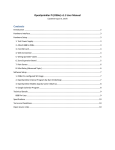
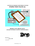
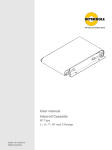
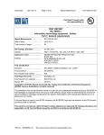
BASIC SETUP AND
INSTALLATION MANUAL
AIM FOR EXCELLENCE
Please read these instructions carefully before
setup and installation of the machine.
Keep this manual in a safe place for future
reference.
Table Of Contents
Safety Precautions .........................................................
1
1. Basic Specifications ...................................................
2
2. Spectrum Avanti
Parts .......................................
3
3. Cabinet Configuration ................................................
4
4. Assembly And Installation Instructions ......................
7
5. Camera Installation And Setup ................................... 11
6. Technical Information ................................................. 12
6A. Exploded Drawing ................................................ 12
6B. I.O. Board Layout ................................................. 20
6C. Main Board Connections
................................... 22
6D. Wiring Diagram .................................................... 23
7. Troubleshooting ......................................................... 24
8. Software Settings ...................................................... 26
9. Program Mode Diagram ............................................. 30
Safety Precautions
Spectrum Avanti
has been engineered and manufactured to ensure
personal safety. However, improper use can result in potential electrical shock
or fire hazard. You must observe the following basic rules for installation, use
and servicing. Failure to do so may defeat the safe guards incorporated into
the Spectrum Avanti
and may result in injury.
Warning
1. It is critical that the step/dart skirt is installed and the board is leveled
prior to opening the upper cabinet door to prevent the game from
falling over.
2. Be extremely careful when moving the dart board into position; leg
levelers may catch on the floor causing the dart board to tip over.
3. Always unplug the power to the dart board before moving.
4. To reduce the risk of fire or electrical shock, DO NOT expose the dart
board to any moisture.
5. To reduce the risk of electrical shock or possible death, DO NOT
touch these areas where high voltage is present; power supply,
voltage terminal strip and lamps.
Caution
1. Before power is connected, confirm the game is level. If the game is
not level/stable, adjust the leg levelers.
2. The Spectrum Avanti
is equipped with a grounded AC line plug.
This safety feature allows the plug to fit into any local grounded power
outlet. If ground is not present in AC system the Aux ground should be
properly connected to the nearest ground point. If you have any problems,
contact a licensed electrician.
3. Operate the dart board from a power source as indicated in the
specification of this manual. If you are not sure what type of power
you have, consult your local power company.
4. Overloaded AC plugs, power strips, extension cords, frayed power
cords and broken plugs may cause system overload and/or fire.
5. DO NOT allow anything to rest upon or roll over the power cord.
6. DO NOT place the dart board where the power cord is subject to
damage.
1
1-Basic Specifications
1. Main Unit
Height
Top Mount
94½” with LCD monitor installed
79¾” without LCD monitor installed
Width
29”
Depth
13¾”
Weight
95 kilos, 209 pounds
Max environment temperature 105 F
Mid Mount
86½” with crown installed
75½” without crown installed
29”
13¾”
94.5 kilos, 208 pounds
2. Step Extension
Height
4½”
Depth
8”
Width
29”
3. Monitor
Screen
17” LCD
4. *Motherboard
Make/model
CPU
Memory
Embedded peripherals
15” LCD
MSI K8MM-V
AMD, Socket 754, Sempron 2600/2800
256 MB/DDR
Audio, video, USB, LAN
5. I.O. Board
Designed and developed by Medalist
I.O. board software version 5.4
6. *Power Supply
Type
Input
Output
Max output power
ATX
120/230 VAC (selectable)
+3.3Vdc/28A
+5Vdc/40A
+12Vdc/12A
-5Vdc/0.3A
-12Vdc/0.8A
400W
*Main board and power supply specifications are subject to change without notice
2
2-Spectrum Avanti
Parts Check List
Unpacking And Inspection
1. Remove Spectrum Avanti
lower cabinet, upper cabinet,
step/dart skirt and LCD monitor/crown from the boxes and
inspect for any damage.
2. Confirm that all parts are included.
Parts List
1. Spectrum Avanti
upper cabinet assembly
2. Spectrum Avanti
lower cabinet assembly
3. LCD monitor assembly
4. Step/dart skirt assembly
5. Hardware kit
A. Step skirt mounting bolts (4)
B. Monitor/crown assembly bolts (3)
C. Key set (2)
6. Accessory kit
A. Bar darts (6)
B. Bar dart tips (1 bag)
C. Throw line (1)
3
4
Front
Side
13) GND Terminal
12) Back Door
(T)
11) Soft Shutdown Switch
7) Mail Slot
10) AC Input
9) Hand Cup
8) Fan-Air Out
Figure 1.1: Cabinet configuration
6) Coin Door
Bill Validator (Optional)
5) Player Button-Yellow
4) Select/Change
Button-Red
3) Target
2) Camera (Optional)
1) LCD Monitor
3-Cabinet Configuration
Back
15) Fan-Air In
(Fan With Filter)
14) Speaker
5
Front
Side
13) GND Terminal
12) Back Door
(M)
11) Soft Shutdown
Switch
7) Mail Slot
10) AC Input
9) Hand Cup
8) Fan-Air Out
Figure 1.2: Cabinet configuration
6) Coin Door
Bill Validator (Optional)
5) Player Button-Yellow
4) Select/
Change Button-Red
3) LCD Monitor
2) Target
1) Camera (Optional)
Back
(Fan With Filter)
15) Fan-Air In
14) Speaker
Technical Information
Name
Item
Function
1 LCD Monitor
For display. Can adjust the display
quality by using the LCD button under
the LCD button cover
2 Camera
For Player and Top Ten List pictures
3 Target
Primarily to register dart scores, also used
to input various information
4
Interfaces with software. Normally this button
Select/
Change Button-Red is used to scroll cursor and change players
5 Player Button-Yellow
Interfaces with software. Normally this
button is used for selecting games and
selecting the number of players to play
the game
6 Coin Door
Where coins are inserted/DBA knockout plate
7 Mail Slot
To send mail to operators/dealers, such
as records of tournaments or league
8 Fan-Air Out
To blow hot air from inside the cabinet out
9 Hand Cup
For transportation and assembly of
the cabinet
10 AC Input
Insert for the AC power cord
11 Soft Shutdown Switch Use for software shutdown (recommended)
12 Back Door
Additional access door
13 GND Terminal
Connects the cabinet ground to earth ground
14 Speaker
Sound
15 Fan-Air In
To bring filtered air from outside the
cabinet in
6
4-Assembly And Installation Instructions
1. Install the leg levelers to the bottom of the lower cabinet.
2. Place the lower cabinet in the desired location and adjust
each leg leveler until the lower cabinet is level from front to
back and side to side.
3. Install the step/dart skirt assembly flush to the floor using
the four bolts provided.
Leg Leveler
Figure 2.1: Installation of lower cabinet
7
A bolt set consists of a
M8 bolt, a lock washer
and a washer
Figure 2.2: Lower cabinet complete unit
Install 1 bolt
from outside
LCD
Monitor Unit
Camera
(Optional)
Install 2 bolts
from inside
Upper Cabinet
Fiber Door
Locks
Figure 3.1: Installation of upper cabinet
(T)
Figure 3.2: Upper cabinet complete unit
(T)
4. Using two people, lift the upper cabinet and place it
on top of the lower cabinet.
5. With someone stabilizing the upper cabinet, open the
back door and lock the four hook latches to secure the upper
cabinet to the lower cabinet.
6. Install the monitor/crown to upper cabinet using the three
bolts provided.
*
7. Route the VGA cable up through the hole in the top of
the cabinet and connect it to the LCD.
*
8. Route the LCD power connector down through the hole in the
top of the cabinet and connect it to the 9 pin power connector
inside the cabinet.
*For top mount board only
8
9. Connect the connectors from the lower wiring harness to the
upper wiring harness.
10. Connect the power cord to power input module on the back
of the cabinet.
11. Adjust leg levelers as needed then proceed to game setup.
12. Double check all of the connections before powering up the
Spectrum Avanti
.
13. Lock the fiber door with key.
Lock hook latches
Connect the lower
harness set with the
upper harness set.
Then connect VGA,
DB9 and Audio cables
to the main board.
Figure 4.1: Install upper cabinet
to lower cabinet
(T)
9
Figure 4.2: Complete unit
installation
(T)
Back Door
Access
Figure 4.3: Open the back door to
lock the hook latches
(T)
10
Figure 4.3: Install upper cabinet
to lower cabinet
(M)
Figure 4.4: Complete unit
installation
(M)
Figure 4.5: Open the back door to
lock the hook latches
(M)
Connect the lower
harness set with the
upper harness set.
Then connect VGA,
DB9 and Audio cables
to the main board.
Back Door
Access
Lock Cabinet
Latches (4)
5-Camera Installation And Setup
(Digital Camera Optional)
Installation
1. Thread the USB camera cable through the 1” hole in the upper
right side of the game.
2. While holding the camera box to the upper right hand side of the
game with the camera hole facing outwards, thread two 6mm bolts
from the inside of the game into the camera box inserts.
3. Plug the USB camera cable into one of the two USB ports.
Setup
1. Press the Program Mode Access Button located on the I.O. board to
enter game setup mode. Go to Diagnostics/Webcam test to set focus.
Go to Game Settings/Player Pix to set pricing and the Photo Delete
password.
Note: The Photo Delete password is set in Game Settings/
Player Pix by using the Yellow Player Buttons to set a numeric
password that corresponds to the Yellow Player Buttons
(i.e. 1111 equals pressing the player one button four times).
The password must be four to eight numbers in length.
2. Adjust focus by turning the black focus ring around the camera lens.
Focus the camera to the distance of the throw line.
3. To access Photo Delete without entering the Operators' Setup Mode,
go to Main Menu/Player Pix. Press and hold the Yellow Player Buttons
two and three simultaneously. This will take you to the enter password
screen. The password is entered by using the Yellow Player Buttons.
Once the password is accepted, follow the screen prompts to
delete photos.
11
12
Hard Drive
And Rack
(Electrical, PE 0608 L)
(Cabinet, PE 0610 L)
Main Board
(Electrical, PE 0601)
I.O. Board
(Electrical, PE 0609)
Ballast-110
(Electrical, PA 0620 1)
Fluorescent Lamp
(Electrical, PA 0619)
(T)
ATX Power Supply (Electrical, PE 0614)
Figure 5.1: Exploded upper cabinet
Mounting StrapPower Supply
(Cabinet, PE 0137)
Fluorescent Lamp Assembly
(Electrical, PA 0618)
Speaker
(Electrical, PA 0626)
Starter-110
(Electrical, PA 0621 1)
6A. Exploded Drawing
6-Technical Information
Cabinet Latch
(Cabinet, PA 0114)
Power Input Module
(Electrical, PA 0623)
Hand Cup
(Cabinet, PA 0121)
Fan
(Electrical, PE 0612)
Camera
(Optional)
Hand Cup
(Cabinet, PA 0121)
13
LCD Button Cover
(Cabinet, PA 0143)
15" LCD Monitor
(Video, PA 0508)
Hard Drive And Rack
(Electrical, PE 0608
Cabinet, PE 0610)
Mounting StrapPower Supply
(Cabinet, PE 0137)
Starter-110
(Electrical, PA 0621 1)
Ballast-110
(Electrical, PA 0620 1)
Fluorescent Lamp
(Electrical, PA 0619)
Fluorescent Lamp Assembly
(Electrical, PA 0618)
Figure 5.2: Exploded upper cabinet
LCD Rack
(Cabinet, PA 0129)
Main Board
ATX Power Supply (Electrical, PE 0601)
(Electrical, PE 0614)
Speaker
(Electrical, PA 0626)
(M)
Cabinet Latch
(Cabinet, PE 0114)
Power Input Module
(Electrical, PE 0623)
I.O. Board
(Electrical, PE 0609)
Fan
(Electrical, PE 0612)
Camera (Optional)
Hand Cup
(Electrical, PA 0121)
14
Player Button-Yellow
(Electrical, PA 0627)
Catch Ring Section
(Dart Head, PG 0221)
Light Diffuser
(Cabinet, PE 0124 R)
Door
(Door, PA 0021)
Select/Change Button-Red
(Electrical, PA 0628)
Catch Ring Screw
(Dart Head, PA 0222)
Figure 6.1: Exploded door
Diffuser Mounting Nut
(Cabinet, PA 0125)
Light Diffuser
(Cabinet, PE 0124 L)
Wing Nut, Star Washer
(Dart Head, PA 0219)
(T)
15
Catch Ring Section
(Dart Head, PG 0221)
Light Diffuser
(Cabinet, PO 0124 R)
(M)
(Dart Head, PA 0222)
Catch Ring Screw
Figure 6.2: Exploded door
Door
(Door, PE 0021 T)
Diffuser Mounting Nut
(Cabinet, PA 0125)
Light Diffuser
(Cabinet, PO 0124 L)
Wing Nut, Star Washer
(Dart Head, PA 0219)
16
Mounting Bolt
(Dart Head, PA 0231)
Figure 7: Exploded dart head
Spider
(Dart Head, PA 0202)
Back Board
Segments:
(Dart Head, PA 0215)
(Dart Head,
Rubber
Center Bull: PA 0203
(Dart Head, PA 0213)
Outer Bull: PA 0204
Pie: PA 0205, PA 0206
Triple: PA 0207, PA 0208
Block: PA 0209, PA 0210
Double: PA 0211, PA 0212)
Target Interface Board
(Electrical, PA 0613)
Switch Matrix
(Dart Head, PA 0214)
Wing Nut, Star Washer
(Dart Head, PA 0219)
17
LCD Button Cover
(Cabinet, PA 0143)
17" LCD Monitor
(Video, PE 0508)
Figure 8: Exploded monitor unit
(T)
LCD Rack
(Cabinet, PE 0129 S)
18
Step Rubber
(Cabinet, PA 0103)
Bolt
(Cabinet, PA 0105)
Washer
(Cabinet, PA 0106)
Bill Validator
(Optional)
Cabinet Latch Assembly
(Cabinet, PA 0114)
Step
(Cabinet, PA 0102)
Figure 9: Exploded lower cabinet
GND Terminal
(Electrical, PE 0629)
Hand Cup
(Cabinet, PA 0121)
Back Door
(Cabinet, PT 0119)
Soft Shutdown Switch
(Electrical, PE 0628)
Lock Assembly # 1111
(Cabinet, PA 0140)
(T)
19
Lock Assembly #2000
(Cabinet, PA 0141)
Bill Validator (Optional)
(Coin Door, PA 0405)
Meter
(Coin Door, PA 0420)
Figure 10: Exploded coin door
Cash Can
(Coin Door, PA 0403 F)
Die Cast Frame Holder
With Hex Flange Bolt
6B. I.O. Board Layout
Port
Description
CN1
CN2
CN3
CN4
CN5
CN6
CN7
CN8
CN9
CN10
CN11
CN12
CN13
CN14
CN15
CN16
CN17
CN18
CN19
CN20
CN21
CN22
CN23
CN24
CN25
CN26
CN27
CN28
Load Program ISP
RS232 Communication
DC Power
Audio Signal Input
Audio Signal Output To Speaker
Target Input
Button/Lights
Input Signal Of Coin Count-Up
Player Change Sensor
Missed Dart Sensor
Bill Validator Input
Soft Power Down
Coin Box Sensor
Spare Input 1
Spare Input 2
Spare Input 3
Spare Input 4
Coin Counter 1
Coin Counter 2
Meter Counter
Flashing Lights
Solid State Switch 1
Solid State Switch 2
Spare Output 1
Spare Output 2
Spare Output 3
Spare Output 4
Spare Output 5
Input Output
4
1
1
16
5
2
1
1
1
1
1
1
1
1
1
-
1
1
4
5
1
1
1
1
1
1
1
1
1
1
1
20
21
5V
GND
12V
POWER
CN3
RS232
CN2
RESET
CN1
LOAD PROGRAM
BV
CN11
PO406BDN
2
HC08
CN/UP
CN8
PCS
CN9
LS541
LS541
MDS
CN10
LS244
POWER RUN
LS244
CN6
TARGET INPUT
CB
CN13
IN1
CN14
16.0
M
ULN2803
CN19
C/CT
IN2
CN15
74HC595D
CN18
C/CT
Figure 11: I.O. board layout
CD
CN12
LS244
MB90F5
62B
74HC595D
CN7
BUTTONS/LIGHTS
IN3
CN16
ULN2803
CN20
METER
IN4
CN17
R9
R8
R7
R6
R5
R4
CN22
SSR1
PROGRAM
MODE
ACCESS
BUTTON
CN21
FL
CN23
SSR2
SPEAKER
CN5
CN28
OUT5
CN27
OUT4
CN26
OUT3
CN25
OUT2
CN4
AUDIO IN
VOLUME CONTROL
M2 D7
M2 D4
M2 D5
M2 D6
M2 D2
M2 D3
M2 D1
CN24
OUT1
6C. Main Board Connections
LAN (Optional)
Mouse
MIC
L-In
Keyboard
Com
VGA
USB
L-Out
Figure 12: Main board connections
Name
AC Power Input
Com Port
VGA Port
USB Port
Audio Signal Out
Function
Supply AC Power To PC
Unit
Serial Communication With
I.O. Board
Send Video Signal To
Monitor
Multi-Function
- Software Update
- Camera
Send Audio Signal To I.O.
Board
Connect to
AC Power
DB9 Cable
VGA Cable
Thumb Drive,
Camera Cable
Audio Cable
22
23
Come With ATX Power Supply
Come With ATX Power Supply
Come With Fan
Main Board
6D. Wiring Diagram
7-Troubleshooting
No Power
1. Check for correct voltage at wall receptacle using digital voltmeter.
2. Check fuse with digital voltmeter or continuity tester.
3. Remove power cord and check wiring from AC power cord to
power supply.
4. Reapply power cord and check for correct voltage at power supply
AC input plug.
5. Check on/off switch with digital voltmeter or continuity tester.
6. Check AC power cord.
No Display On LCD
1. Check power to LCD.
2. Check the VGA cable.
3. If the main board appears to be booting up and there is still no
display, the LCD may need to be replaced.
No Sound
1. Check the volume control on the I.O. board.
2. Check for proper connections at the main board, I.O. board and
speaker.
3. If the connections are good and there is still no sound, the
speaker may need to be replaced.
No Lamps
1. If one side is working, swap lamps and starters to determine if
either is defective.
2. If neither side is working, check for correct voltage at the lamp
connector located just below the lamp holder.
3. If the voltage is correct, install a new lamp and/or starter.
24
No Lamps (Continued)
4. If voltage is not present, trace the wiring back to the terminal strips
located behind the power supply using a digital voltmeter.
5. If voltage is present but lamps do not work, install a new lamp
holder.
No Coin-up
1. Check wiring from the coin switches to the I.O. board connector
CN 8.
2. Manually short ground pin to the center pin of connector CN 8
on the I.O. board using a small metal screwdriver and check for
coin-up.
3. If the dart board can be manually coined-up at the I.O. board, the
problem is the wiring or the coin switches.
4. If the dart board cannot be coined-up at the I.O. board, the
I.O. board may need to be replaced.
Stuck Segment
1. Unplug the ribbon cable from the target interface board. If the
stuck segment error message goes away, the problem is in the
dart head assembly.
• If the problem is in the dart head assembly, first remove and
clean the rubber and matrix and remove all tips from behind the
rubber as well as in and around the target segments
• The rubber may need to be replaced if it is severely indented
• The matrix may need to be replaced if the problem still exists
2. Unplugging the ribbon cable from the target interface board does
not eliminate the stuck segment error message, re-install ribbon
cable into the target interface board and remove the other end
from the I.O. board located inside the upper cabinet.
• If the problem goes away, the ribbon cable may need to be
replaced
• If the problem does not go away, the target interface board may
need to be replaced
25
8-Software Setting
To access the Spectrum Avanti
software on the I.O. board, find
and press the S2 PM black button on the I.O. board. This will take you
to the Program Mode. Changes to Games, Display, Date & Time, the
File and the Board itself can be made from here. You may also run
Diagnostics and check Reports. Use the Red Player Change Button to
scroll to a desired category and then any Yellow Player Button to select
that category.
Selecting Game Settings
1. 01 Games
2. Cricket Games
3. Practice Games
Selecting any of these first four options will allow you to choose
if the game is displayed or not, the Happy Hour and Regular
Price Credits, Round Limit, Single or Double Bull, Robo Rival
(depending on game), Extended Play Credits and Extended Play
Rounds
4. Goodtime Games
5. Game Options
Selecting this brings up a submenu with 01 Games, Cricket
Games, Goodtime Games, League Settings, Match Play Settings,
and General Settings
The first three: 01 Games, Cricket Games and Goodtime Games,
will show the options for those games. Selecting the option will
allow you to take it off the menu or charge for using the option
in a game
General Settings will allow you to change the number of times
Correct-A-Dart can be used. General Settings allows you to turn
on/off Handicapping, Non Cut-Throat Games, Medalist Rating,
Out Chart Displayed and Freeze Warning
You can also set the pricing for Doubles and Trios in League and
select the stat format (PPD/PPR)
League Settings will allow you to set the pricing for Doubles, Trios
and Playoffs. You may also disable auto handicap
26
Selecting Game Settings (Continued)
6. Player Pix Options
Set Happy Hour and Regular Pricing. Password allows you to
give a password to the location in case they would like to delete
pix that have been placed on the board thus saving a service call
(to use set password enter Player Pix screen and press Yellow
Player Buttons 2 and 3 simultaneously
Enter password using player buttons and follow instructions to delete).
Set the amount of time before the picture is snapped and set the
number of times a password may be tried and also time between
password retry
Selecting Display Settings
1. Language
Changes instructions to the selected language
2. Top Ten List
Brings up submenu with Count-Up, Cricket Count-Up, Eagles Eye,
Half-It, Super Count-Up and Super Cricket Count-Up
Selecting any of these will allow you to view and edit list, clear
current list and set the amount of time before the list clears
automatically or if the list is displayed at all
Selecting Date & Time Settings
1. Date & Time
Changes date and time displayed by the board
2. Pricing
Displays the days of the week. By selecting a day you can change
the pricing for any hour during that day from Normal Play to
Happy Hour or Free Play
3. Auto Soft Shutdown
This allows you to set a time when the board will shut down
Selecting Report
1. Event Log
Displays all events that happened on the board (i.e. stuck segments
or buttons)
2. Counters
Shows coin and bill amounts that have gone into the board
27
Selecting Reports (Continued)
3. Delete Credits
Clears any credits currently on the board
4. Delete Photos
Brings up a screen to show you how to delete any photos
currently on the dart board
Selecting Diagnostics
1. Matrix
A target will appear on screen. To check your Matrix touch
segments on the dart board and see if they correspond to the
screen
2. Button & Lights
A button panel will appear on screen. Press buttons to test
3. Coin/Bill Latch Test
Insert coins or bills and screen will show amount inserted
4. Audio Test
A small audio clip will run
5. Video test
Test using several standard formats
6. Webcam Test (Digital Camera)
Displays camera view, adjust if necessary
Selecting Board Setting
1. Credit Settings
Choose credits for pulses to be selected
2. Anti-Free Darts
Turn on or off and select amount of darts thrown before
warning will sound
3. Operator Settings
Turn on or off: Power Recovery, Extended Play,
Erase Credits Timer and Free Play features
Change the amount of time from when a player hits the
Red Player Change Button to the next player’s turn
Enable or disable Automatic Player Change and change
the amount of time between player’s turn
Enable or disable Match-It
28
Selecting File Load Setting
Selecting file load setting allows you to load either Factory Settings 1, 2 or 3.
Game
Factory Setting 1 Factory Setting 2 Factory Setting 3
01
301
501
701
901
1101
1501
Cricket
Standard
Random
Select-A
Hidden
U Pick-I Pick
Team
Practice
Count-Up
Cricket Count-Up
Eagles Eye
Rotation
Polarity
Super Count-Up
Super Count-Up Crkt
Goodtime
Air Attack
Out-On-A-Lim
Ladies & Gentlemen
Splat
Half-It
1
2
3
4
5
6
3
3
3
3
3
3
1
2
3
4
5
6
2
2
2
2
2
2
1
4
4
4
4
4
4
4
4
4
4
4
1
1
1
1
1
2
2
1
1
1
1
1
1
1
2
2
2
2
2
3
3
2
2
2
2
2
1
1
1
2
1
2
2
2
2
2
Figure 13: Factory settings
29
Counters
Delete Credits Delete Photos
301
501
701
901
1101
1501
01
Games
Cricket
Games
Practice
Games
From (Date)
To (Date)
Good Time
Games
Game
Options
Extended Play Credits
Extended Play Round
Bullseye S/D
Robo Rival (Y/N)
Depending On Game
Round Limits#
Regular Play
Credits#
Happy Hour
Credits#
Display On Menu
(Y/N)
Random
Standard
Options
Displayed(Y/N)
Single Option
Cost
Multi Option
Cost
Exit
Shanghai
Dbl In
Dbl Out
Master Out
Parity Play
Fast Finish
No Bull
Team Play
Split
01
Games
Button
& Lights
Press Button
To Test
Audio
Test
Pressing Will
Play A Small
Audio Clip
Coin Bill
Latches
Screen Has 3
Latches
Left Coin
Right Coin
Bill Validator
Player Pix
Options
Options
Overkill
Feature
(Y/N)
General
Settings
Cricket
Games
League
Settings
Single Option
Cost#
Multi Option
Cost#
Display Menu
(Yes/No)
League Dbls
Options
Credit/Ply $
Nudity
Settings
League Trios
Credit/Ply $
Splat
Playoff Dbls
Credit/Ply $
Half-It
Playoff Trios
Credit/Ply $
Auto Handicap
Options
(On/Off)
Displayed (Y/N)
Ladies &
Gentlemen
Good Time
Games
Selecting Will
Give You
That Screen
Cross Hatch
Color Bar
Black Screen
White Screen
Borders
Video
Test
Pressing Will
Allow You To
View The
Camera And
Adjust Focus
Web Cam
Test
Bill Validator
#Pulse
=#Credits
Right Coin Slot
#Coin
=#Credit
Left Coin Slot
#Coin
=#Credit
Match Play Settings
Correct-A-Dart
Limit#
Handicapping
(On/Off)
Non Cut Throat
Games (Y/N)
Stat Format
PPR/MPR (100%)
Medalist Rating (Y/N)
Out Chart Displayed
(Y/N)
Freeze Warning (Y/N)
General
Settings
Factory 1 Settings
Factory 2 Settings
Factory 3 Settings
Selecting Will Load
Setting
Load Settings
Free Darts
#Of Darts
Enabled
(Y/N)
Credit Settings Anti-Free Darts
To access the program mode press and hold the S2 PM
button in the upper left hand corner of the I.O. board
Press Player
Change Button
To Exit
Symbols Will
Press Player Press Segment Appear When You
Coin-Up
Change To Exit
To Exit
Game
Touch Each
Segment
To Test
Screen Shows Shows A Button
Dart Board
Panel
Matrix
Happy Hour
Count-Up
01 Games
Air Attack
Credits#
Super Count-Up Out-On-A-Lim Cricket
Games Regular Price#
Cricket Count-Up
Ladies & Good Times Password#
Select-A
Super Cricket Gentlemen
Games
Retry#
Hidden
Count-Up
League
Capturing
Splat
Settings
U Pick-I Pick Rating Test
Delay (Secs)#
-10 Gms
Match Play
Team
Half-It
Eagles Eye
Settings
Password
Rotation
General Delay (Mins)#
Polarity
Settings
From (Date)
To (Date)
Selecting Will If No Photo
Delete Credits Press Player
On The Board Button To Exit
Non-Resetable
Time And Day Counter Total And Keep You Press Player
In The Report
Of Event
L R Bill
Change Button
Screen
####
For Next Pix
Resetable
If None To
Display Press Counter Total
Hit Any Target
L R Bill
Player Button
Segment To
####
Delete Pictures
Service Counter
Total L R Bill
####
Event Log
Click Player
Button To Change
Settings
Month
Day
Year
Hour
Minute
AM/PM
Date & Time
Language
(Select)
Language
Top Ten List
(On/Off)
View/Edit List
Clear
Current List
Names Clear
After
# Of Weeks
Count-Up
Cricket Count-Up
Eagles Eye
Half-It
Super Count-Up
Super Cricket
Count-Up
Top 10
List
Display Settings
Match-It
Enable/Disable
Power Recovery
(On/Off)
Overtime
Extended Play
Sudden Death
(On/Off)
Erase Credits
Timer
(On/Off)
Player Change
Delay
(#Seconds)
Automatic
Player Change
(#Seconds)
Free Play (Y/N)
Operator
Settings
Sunday
Monday
Tuesday
Wednesday
Thursday
Friday
Saturday
Pricing
Enable
(Y/N)
Hour
X
Minute
X
AM/PM
X
Auto Soft
Shutdown
Program Mode Diagram
30
Medalist Marketing Corporation
201C Frontage Rd. N.
Pacific, WA 98047 USA
Tel: 1-253-939-2900 Fax: 1-253-939-0128
Medalist USA Asia
2F Nihon Build Mihashi 1 Chome Bldg.
1-1201 Mihashi, Omiya-ku, Saitama-shi
Saitama 330-0856 Japan
Tel: 81 (0) 48-648-5346 Fax: 81 (0) 48-648-5347
Medalist Asia Limited
50/8-9 Moo 5, Salaya-Nakorn Chaisri Rd., Salaya,
Phuttamonton, Nakornpathom, Thailand 73170
Tel: 66 (0) 2800-2737 Fax: 66 (0) 2800-2650
Mida-Medalist Entertainment Public Co., Ltd.
96/2 Moo 4, Tambol Lamphaya, Amphur Muang
Nakornpathom, Thailand 73000
Tel: 66 (0) 3427-2581-3 Fax: 66 (0) 3427-2585
www.medalistgames.com