1
Service
Manual
Generator and
Controls
Description
Troubleshooting Chart
Testing Procedures
Repairs
Wiring Diagrams
900-0196
9-96
Redistribution or publication of this document
by any means, is strictly prohibited.
Safety Precautions
Before operating ttre generator set, read ttte Optator's
Manual and b e m e familiar with it and the equipment. Safo
and sfficlnnt operation can be achiovsd onty If ttto unit i t
properly operated and maintained. Many accidents are
caused by failure to fdlow fundamental rdes and precautions.
o not wear l o w clothing or jewelry while mrwicing any
part of the generator set. LOSS doihing and jewelty GXI
become caught in moving park Jewelry can short out
electrical oontacts and cause shock or burning.
If adjustment must be made while ttrs unit is running, urn
extreme caution around hot rnanifoids, moving pa&. etc.
The followtng symbols,found throughout this manual, alert you
to potentiallydangerouscwtditionstotheoperator, service per-
sonnel. or the equipment.
ELECTRICAL SHOCK WILL CAUSE SEVERE
PERSONALINJURY OR DEATH
TItls symbol warns of immediate hazards whlch wlll result In severe personal Injury or
death.
Remove 8Iectricpower before rarnovingpratectiveshfe1d.r;
or touching electrical equipment. Use rubber insulabiw
mats placed on dry w d platfarms aver Rmrs that are
metal or mcrete when around electrical equipment Da
not wear damp clothing (particularlywet shoes)or al6ow
skin surfaces to be damp when handling eleetrical equip-
n m N q Thissymbolrefersio a hazard or unsafe
practice whkh can result in severe pemnal h j u y
or death
ment.
Use extreme caution when waking on electrical components. Highvoltages rn cause injury or death, P
1
I
b3iKunQN I ?hlssymbolmfersio a hazard or unsafe
pxactlce Wlch c%nresult In pmonal Injury orproduct or property damage.
tamper with interlocks.
FUEL AND FUMES ARE FLAMMABLE. Fire, explosion, and
Follow all state and local electrical 8s. Have all eladrical installations performed by a qualrfied fimnsed electrician. Tag open switches to avoid accidental dosure.
personal injury can result fram improper practices.
DO NOTCONNECTTHE GENERATOR SET DIRECTLY
TO ANY BUiLDfNG ELECTRICAL POWER SYSTEM.
Hazardous voitages can R
w &om the generator set into
the utili line. This creates a patential far slectrenrtim or
propertydamage. Connect only through ati approved deVice and after building main switch is opn. GonsuH an
electrician in regad to emergency power use.
NOT fill fmlfankswiththeenginerunning unlesstanks
oreowtsldetheengine compartment. Fuel contact with Rot
engina M exhaust is a potential fire hazard.
50NOT SMOKE OR ALLOW AN OPEN FUME near the
generator set or fuel tank. Internal combustionengine fuels ars highly flammable.
Fuel lines must t;s adequately searreci and free of leaks.
Fuelconnectionsat theengineshould bemadewithanapproved fXexibleiine. Do not use copper piping on flexible
lines as copper will work harden and beoome brittle.
GENERAL SAFETY PRECAUnONS
Provide apprupriate fire extinguishersand insfallthem in
convenient locations. Consult your Imal fire department
forthecorrecttypeof sxtinguishsrtause. ~ ~ R ~
on electrical fires. Use extinguisher rated A3C by NFPA.
Ele sure that all fuel supplies have a positive shutoff valve.
RQ NDTSMOKE while servicingbatteries. Leadacid batteries emit a highly expksive hydrogen gasthat can be ignited by electrical arcing or by smoking.
Provide an adequate exhaust system to properlyexpel dbcharged gases. Inr;per;2fieexhaust system daily far leaks
per the maintenance schedule. See fhat edtausf manifolds .are secure and are not warped. Do nat use exhaust
gae: to heat a compartment.
or adding gasoline. take care not to ingest. breathe t h
fumes, or contact gasoline.
Make sure Sfiat rags are not left
or near the engine.
Keep your hands away from moving parts.
Remove all unnecessary Qreasoand ail horn the unit. Accumulated grease and ail can MUS^ over heating and engine damage, and present a potential fire hazard.
Bsfore petfarming any maintenance on the generatorset,
disctxlnect the starting battery negative (-) ground lead
had first. This will prevent a
Keep the generator set and the surraunding area dean
and free from obstructions. Remove any debris from the
set and keep the floor clean and dry.
Make sure that fastsners on the generator set are secure.
g
~clamps, keep
~ guards,in position
~ ower
fans, drive belts, etc.
s
Benzene d lead, fourid in soma gasoline, have h e n
identifiedby some state and federal agsncies as c a u ~ w
cancer or reproductive loxicity. When checking, draining
Be sum tfts unit is welt usntilated.
MOVING PARTS CAN CAUSE SEVERE PERSONAL
INJURY OR DEATH
~
~
Usedengineoilshave beenidentified bysmestat&xfdera1 agencies as causing cancer Or reproductive toxicity.
When chec)cingor changingengine Oil, take care not to ingest, breathe the fumes, or c~ntaetused oil.
EXHAUST GASES ARE DEADLY
0
-
~
DDnofworkOn~isetlujpmenfwhenrnenlallyar physiwlly
~
~
~ afcakal~GI drug that
a
fatigued,
or ~affer consuming
any
makes the operation of e q ~ i p t ~unsafe.
~~nt
ss-7
~
Redistribution or publication of this document
by any means, is strictly prohibited.
e
Table Of Contents
PAGE
SECTION TITLE
SAFETY PRECAUTIONS..........................................
1
2
Inside front cover
1-1
Test Equipment ............................................................
1-1
1-2
Load Wire Connections .....................................................
1-4
Reconnectible Single-phase Generator .......................................
Three-phase Delta Wound Generator ........................................
1-4
1-6
Three-phase Wye Connected Generator ......................................
GENERATOR ................................................................
2-1
Generator Disassembly ..................................................... 2-1
2-3
Generator Troubleshooting ..................................................
Generator Service Procedures and Tests
2-4
2-11
Generator Assembly .......................................................
CONTROL SYSTEM ..........................................................
3-1
Operation Description ......................................................
3-1
3-1
NBModels ................................................................
3-2
MCCK (Spec D) and NH (Spec A through C) Models............................
CCK (Spec R). MCCK (begin Spec E). and NH (Spec D through F) Models ........ 3-4
BF. CCK (begin Spec U). LK (begin Spec M). and NH (begin Spec J) Models ...... 3-6
BFA (Spec A). BGA (Spec A). and NH (Spec K) Models .......................... 3-7
3-8
MCCK Spec H Models ......................................................
TROUBLESHOOTING ........................................................
4-1
4-1
NBModels ................................................................
4-5
MCCK (Spec D) and NH (Spec A through C) Models............................
CCK (Spec R). MCCK (begin Spec E). and NH (Spec D through F) Models ........ 4-9
4-16
BF. CCK (begin Spec U). LK (begin Spec M). and NH (begin Spec J) Models
BFA (Spec A). BGA (Spec A). and NH (Spec K) Models ......................... 4-20
POWER DRAWER MODELS.......................................
.:.......... 5-1
Generator Disassembly .....................................................
5-1
Generator Troubleshooting Guide ............................................5-2
5-4
Generator Service Procedures and Tests .....................................
WIRING DIAGRAMS..........................................................
6-1
INTRODUCTION .............................................................
.....................................
3
4
.....
5
6
i
Redistribution or publication of this document
by any means, is strictly prohibited.
.
Redistribution or publication of this document
by any means, is strictly prohibited.
Introduction
.
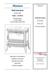
TEST EQUIPMENT
This manual providestroubleshootingand repair information for Onan UN generators. It includes procedures for
repairing the generator and control system. This information does not apply to the engine; engine information
is provided in the ENGINE Dortion of the Master Service
Manual (922-0501).
Most of the tests described inthis manual can be made
with an Ac-Dc multimeter,
Other test equipment
includes:
0 Onan Multi-Tester 420-0303
0 Wheatstone or Kelvin bridge (tests resistance values
below one ohm)
0 Continuity tester (6 volt)
Jumper wires
Onan loadtest panels420-0413,420-0414,420-0501
0 Onan armature growler 420-0194
Many troubleshoofingprocedurespreIAWAR"G1
sent hazards which can result in
severe personal injury or death. Only qualitied service
personnel with knowledgeof electricityandmachinery
hazards should perform service procedures. Review
safety precautions on inside cover page.
Electrical shock can cause severe
personalinjury ordeafh. Do nottouch
electrical wiring or components during testing. Disconnect electricalpower by removing the sfariing battery negative (-)cablebeiore handling electrical wiring
or components.
Electrical shock can cause severe
(BWARNINGI personalinjuryordeath.Useextreme
caution when working on electrical cjrcuitry. Affach
and removemeter leads only when generator set is not
operating. Do not touch meter or meter leads during
testing.
FIGURE
1-1. TEST EQUIPMENT
1-1
Redistribution or publication of this document
by any means, is strictly prohibited.
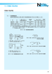
LOAD WIRE CONNECTIONS
The genset nameplate displays its electrical output
rating in watts, volts and hertz. Table 1-1 lists these
figures for gensets using the UN generator. Contractor
and portable gensets are prewired, and include a
receptacle box with b o duplex 12O-volt, 15-ampere
grounding receptacles and two 240-voltI 20-ampereI
twist-lock receptacles(Figure 1-2). Figures 1-4 and 1-5
show the electrical circuitsand connectionsfor various
voltages on all other UN-based generator sets.
7
1
Electrical shock can Cause severe
*WARN"G
personal injury deafh. Check vol-
or
fageat the maiflhJftCtiOn box tobe SurepoWefhaSbeefl
disconnected before disconnecfing load wires.
TABLE 1-1. ELECTRICAL DATA FOR UN GENERATORS
60 HERTZ, 800 r/min
GENERATOR SET
SERIES
LK (RV)
NB
BF (RV)
BF (Power Drawer)
BFA (RV)
BGA (RV)
~
WATTS
2500
3000
4000
4000
4000
5000
VOLTAGE
1201240
1201240
1201240
120
120
1201240
PHASE
1
1
1
1
1
1
AMPERES
21110.5
25112.5
34117
34
34
42121
CCK
MCCK
CCK
MCCK
4000
4000
5000
6500
1201240
1201240
1201240
1201240
1
1
1
1
34117
34117
42121
54127
NH
CCK
CCK
CCK
6500
4000
5000
5000
1201240
1201208
1201208
1201240
1
3
3
3
54127
11*
14*
12*
CCK
NH
NH
NH
NH
5000
6500
6500
6500
6500
NB
CCK
MCCK
CCK
2300
3500
3500
4200
3
2771480
3
1201208
3
1201240
3
2771480
1
120
50 HERTZ, 500 r/min
1
1201240
1
1201240
1
1201240
1
1201240
NH
MCCK
CCK
5500
5500
4200
1201240
1201240
1201240
1
1
3
46123
46123
1o*
CCK
NH
NH
4200
5500
5500
2201380
1201240
2201380
3
3
3
6.4*
13.2"
8.4"
STACK LENGTH
Inches
(mm)
3.1 2
6"
18"
15.5"
7.8"
50
1919.5
30115
30115
35117.5
5.50
5.50
5.50
(140)
(140)
(140)
*Current rating for three-phasevoltage only (higher nameplaterating).
(RV) Special generator set model for recreationalvehicles.
1-2
Redistribution or publication of this document
by any means, is strictly prohibited.
The AC output box has openings for load wires (Figure
1-3). Connect each load wire to the proper generator
Output lead inside the AC output box (descriptions
following). hsulate the bare ends of ungrounded wires.
Install a fused main switch (or circuit breaker) between
the generator set and the load.
Meet all applicable code requirements. A qualified
serviceman or electrician must install the genset, and
the installation must be inspected and approved. Use
flexible conduit and stranded load wires near the set, to
absorb vibration. Strip enough insulation from the wire
ends for clean connections.
Electrical shock can cause severe
personal injury or death. Check volfage at the mainjunction box to be sure power has been
disconnected before attempting load wire disconnecfion/reconnecfion.
.
CONTRACTOR MODEL SHOWN
24O-VOLT,
TWIST-LOCK
120-VOLT, 15 AMPERE
.DUPLEX RECEPTACLES
M-1773
FIGURE 1-2. CONTRACTOR AND PORTABLE GENSETS
OTHER RV MODELS
"POWER DRAWER" MODELS
STANDARD MODELS
3,
BOX
GROUND LUG - GROUND
GENERATOR SET TO
CLEAN, BARE GROUND
ON VEHICLE FRAME
CONNECTION
BOX .
KNOCKOUTS
ES-1810
FIGURE 1-3. AC OUTPUT BOX LOCATION
1-3
Redistribution or publication of this document
by any means, is strictly prohibited.
ReconnectibleSingle-phase Generator
Usethe connection for two-wire service when one load
exceeds one-half rated capacity. Balance the load
when connecting for three-wire service. Currentfor any
one output lead must not exceed the nameplate rating.
Serious overloading can damage the generator windings. When two or more single-phasecircuits are available~divide the load equally among them.
Electrical shock can
severe
1 -tage at the vehiclepersonalinjury
or death. checkvoltjunction box io be sum power has
been disconnected beiore attempting load wire disc on n e c t i 0 n / r e c 0 n n e c f io n , Re c 0 n n e ct i b / e
single-phase generators can supply the fo/lowing volfages (Figure 7-4);
,
720/240 volts, 3 wire
720 volts, 2 wire
240 volts, 2 wire
1 2 0 VOLT, 2 WIRE
UNGROUNDED LOAD WIRE
240 VOLT, 2 WIRE
In
n
M1. M 3
(LJOIN)
(BLACK)
u)
t
w
-I
120 V.(FuII nameplate rating)
(JOIN AND
GROUND)
M3
(BLACK)
GROUNDED LOAD WIRE
w
z
(WHITE)
Lu
-I
MI. M4
(JOIN)
M2
0
2
5
(3
(3
7
5
II:
V. (Full nameplate rating)
0
(WHITE)
0
UNGROUNDED LOAD WIRE
a
I D 0 NOT USE FOR "RV')
I
NOTE: Only half nameplate
rating can be taken off each
120 volt connection.
t
120
240
v.
+
t
120
II:
v.
GROUNDED LOAD W I R E (WHITE)
0
IM2, M 3 (JOIN) Q:
U
w
v.
ES-1811
FIGURE 1-4.120/240 VOLT RECONNECTIBLE GENERATOR LOAD CONNECTIONS
1-4
Redistribution or publication of this document
by any means, is strictly prohibited.
Three-phase Delta Wound Generator
120/240 Volt (Code 5D)
Connect the “hot” (black) load wire to either M1 or M2
for 120-volt single-phase service. Connect the neutral
(white) wire to MO. Two 120-volt circuits are available.
Electrical shock can cause severe
b%@@
personalinjury or death. Check voltage at
mainjunction box to be surepower has been
Do not use MO and M3 as a 120-volt circuit.
fhe
For single-phase 240-volt service, connect the load
between M1 and M2, or between M2 and M3, or
between M1 and M3 (three circuits available). MO is not
used.
disconnected before attempting load wire disconnection/reconnection. Three-phase delta-connected
generafor sets can supply fhe following voltages (figure 1-5):
Any combinationof single-phase and three-phase loading can be used if no one terminal current exceeds the
generator nameplate rating. Single-phase loads as
large as two-thirds of the three-phase rating may be
used if no other load exists on the generator.
7 20- volt, single-phase current
24O-volt, single-phase current
240-vo/t, three-phase current
For three-phase operation, connect the three load wires
to the three terminals M1, M2 and M3, one wire per
terminal. MO is neutral, and is not used for three-phase
operation.
DELTA GENERATOR CONNECTlONS FOR VOLTAGE CODE -5D
3 PHASE
UNGROUNDED LOAD WIRE
(BLACK)
UNGROUNDED LOAD WIRE
GROUNDED LOAD WIRE
(WHITE)
FIGURE 1-5. THREE PHASE 1201240 VOLT (DELTA)
GENERATOR LOAD CONNECTIONS
1-5
M2
M3
MQ
Es-1812
Redistribution or publication of this document
by any means, is strictly prohibited.
Three Phase (Wye Connected) Generator
1201208 Volt (Code 4)
2771480 Volt (Code 4X)
For three-phase current, connect separate load wires to
generator terminals M1, M2 and M3.Single-phase current is found between any two three-phase terminals.
If using single-phase and three-phase current at the
same time, take care to balance the single-phase load
properly.
Electrical shock can cause severe
lage
eWAR"G1
personal injury or death. Check voltat the main junction box to be sure power has been
disconnectedbeforeattemptingload wiredisconnection/
reconnection.
Continuous generator set overload@
!
ing
@
can causehigh
@
operating temper!I
atures that could damage the generator windings. Use
Three-phase (wye-connected) generator sets produce
single-phase voltage of the lower nameplate voltage
(e.g. 120 volts) and three-phase voltage of the higher
nameplate voltage (e.g. 208 volts). The MO terminal is
grounded. For single-phase current, connect the neutral
(white) load wire to MO. Connect the "hot" (black) load
wire to either M1, M2 or M3. Three separate singlephase circuits are available, each having no more than
one-third the rated genset capacityfrom any one circuit.
any combination of single-phase and three-phase
loads, as long as the current in each load line of the
generator does not exceed rated current.
i { {
W E GENERATOR CONNECTIONS FOR VOLTAGE CODES 4 (120/206) and 4X (277/480)
UNGROUNDED LOAD WIRE
3-PHASE
HIGHER
NAMEPLATE
VOLTAGE
UNGROUNDED LOAD WIRE
UNGROUNDED LOAD WIRE
(BLACK)
A
GROUNDED LOAD WIRE
(WHITE)
A
- Lower nameplate voltage,
I phase circuit.
M2
M3
A
A
--
MO
6 - Higher nameplate voltage, Iphase circuit.
ES-1813
FIGURE 1-6. THREE-PHASE, FOUR WIRE (WYE)
GENERATOR LOAD CONNECTIONS
1-6
Redistribution or publication of this document
by any means, is strictly prohibited.
Section 2. Generator
~
~
t
h
e
h
k@?@&l
sion, which can result in severe
personal injury. Because batteries produce explo-
Onan Power Drawer gensets and controls are described in a separate section of this manual.
GENERATOR DISASSEMBLY
.
f
sive gas, do not smoke orallow any arc-producing
devices in the battery area. To avoid excessive
arcing, always disconnect the negaiive (-) cable
first, and connect it last.
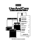
Before disassembling the generator, mark all leads and
note their connection points. Figure 2-1 illustrates a
typical generator parts breakdown.
Inadvertent starting of the
generator set can cause damage
to the generator set, severe personal injury, or
death. For this reason, do not reconnecf the negative (-)battery cable untilinstructed to do so in this
procedure.
Many service procedures present
hazards which can result in severe
personal injury, death, and/or equipment damage.
Only qualified service personnel with knowledge of
fuels, electricify, and machinery hazards should perform service procedures. Review safety precaufions
on inside cover page.
@@!!&I
2. Remove the control leads and other electrical leads
to the engine.
3. Disconnectthe load wires from the generator output
wires in the AC output box.
4. Remove all accessories attached to the generator.
5. Remove the generator fan cover and end bell
wrapper.
6. Loosen and lift out the brush rigs, or use wooden
dowels or alligator clips to hold the brushes out of
the way, to remove the end bell.
1. Disconnect the battery cables from the generator
set, negative (-) cable first.
WRAPPER
1
COLLECTOR RINGS
COMMUTATOR 7
o
ARMATURE BEARING
DC CONDENSER
m
FAN COVER
FRAME ASSEMBL
BRUSH BLO
FIGURE 2-1. TYPICAL GENERATOR DISASSEMBLY (EARLY MODELS)
2-1
Redistribution or publication of this document
by any means, is strictly prohibited.
1 - ACAUT'oN
The brushes may be damaged
during removalif not heldoff the
slip rings. Make certain to hold the brushes out of
the way before removing the generator end bell.
12. While pulling outward on the armature with one
hand, strike a blow on the end of the armature
through-stud with the nut on the stud, to loosen the
armature. Remove the armature and drive hub as a
unit. Do not lose the key from the drive hub on the
engine shaft.
7. Remove the generator fan, mounting nut and
washer.
6
If the armature does not come loose, place a heavy
brass rod on the armature shaft near the ball bearing and strike a sharp downward blow on the rod
with a hammer. Rotate the armature 180' before
repeating.
8. Remove all the generator wire leads from the end
bell assembly.
9. Remove the four generator through-bolts.
1-
Inadvertently striking the commutator, collector rings or bearing can damage these parts severely. Use extreme
care when performing this procedure.
10. Lift or pull the end bell from the frame assembly (do
not pry with a screwdriver). Tap aroundthe edges of
the end bell with a plastic hammer.
11. Remove the frame assembly. Screwdriver slots in
the engine-generator adapter enable the frame to
be pried loose. Be careful not to let the frame rest or
drag on the armature during removal.
13. Remove the engine-generatoradapter by removing
the mounting screws.
2-2
Redistribution or publication of this document
by any means, is strictly prohibited.
GENERATOR TROUBLESHOOTING
Many troubleshootingprocedures present hazards which can result in severe personal injury or
death. Only qualified servicepersonnel with knowledge of fuels, elecfricity, and machineryhazards
should perform service procedures. Review safety precautions on inside cover page.
TROUBLE
NO AC VOLTAGE
POSSIBLE CAUSE
1. Blown fuse or circuit
breaker (if used)
2. Disconnected wire or
lead brushes.
3. Brushes not making contact
with collector rings.
4. Open, grounded or short circuit
in field or armature winding.
LOW AC OUTPUT
1. External short circuit on line.
2. Generator overloaded.
3. Shorted or grounded circuit in
field or armature winding.
4. Engine not running properly
causing generator to slow
NOISY GENERATOR
GENERATOR
OVERHEATS
1. Defective bearing in end bell.
2. Brush rig loose.
3. Armature and field frame
rubbing together.
1. Generator overloaded.
2. Windings and parts covered
with oil or dirt.
3. Air intake restricted or
incoming air too hot.
4. Shorted, open or grounded
circuit in armature or
field windings.
2- 3
CORRECTIVE ACTION
1. Look for cause and repair.
Then replace fuse or reset
breaker.
2. Reconnect wire or wires.
3. Check brush springs for free
movement or brushes which
may be excessively worn.
4. Test with ohmmeter or
continuity tester and repair or
replace as necessary.
1. Locate and eliminate short
circuit problem.
2. Remove part of load.
3. Test with continuity tester or
ohmmeter and replace
if defective.
4. Refer to Engine SectionTroubleshooting.
1. Replace bearing.
2. Retorque.
3. Check generator alignment and
clean air gap between arm and
field of varnish lumps.
1. Remove part of load.
2. Clean generator.
3. Take necessary steps to allow
for proper cooling.
4. Test with ohmmeter or
continuity tester and replace
if defective.
Redistribution or publication of this document
by any means, is strictly prohibited.
GENERATOR SERVICE PROCEDURES AND
TESTS
Brush Replacement
Install new brushes when the old ones are worn to the
dimensions shown in Figure 2-2. Replace the brush
springs if they aredarnaged, or if their correct tension is
doubtful.
MEASURE FROM TOP FACE OF
BRUSHBLOCKTOTOPOFBRUSH
6-1218
6-1217
FIGURE 2-3. GENERATOR BRUSH REMOVAL
Using the wrong brush can
AcAUT~ON damage
or destroy the generator. Never substitute a brush which appears to be
the same, because if may have difierent electrical
characteristics. Always use the correct Onan
brush (correct part number listed in parts catalog).
6. Install the brush blocks and the generator end bell
wrapper.
FIGURE 2-2. MEASURING BRUSH WEAR
New brushes are shaped to fit, and seldom need sanding to fit properly. If brush sparking occurs, run the
generator set with a light load until the brushes are
properly seated.
1. Remove the generator end bell wrapper to expose
the brushes.
2. Measure the brush wear.
3. Remove the threescrews holding each brush block
in place (Figure 2-3).
4. Remove the old brushes and clean the holders so
the new brushes can move easily in their holders.
5. Install the new brushes.
2-4
Redistribution or publication of this document
by any means, is strictly prohibited.
1-
lncorrect use of a lathe or other
power tools can cause severe personal injury, death, or equipment damage. Service
personnel must be fully qualified to operate a lathe
before attempting this service procedure. Wear eye
and hand protection while performing this procedure.
Collector Rings and Commutator
If the collector rings are so grooved or pitted that good
brush seating cannot be maintained, remove the armature and refinish the collector rings in a lathe. If the
commutator appears rough or scored, refinish it at the
same time.
lncorrect use of a lathe or other
power tools can cause severe personal injury, death, or equipment damage. Service
personnel must be fully qualified to operate a lathe
before attempting this service procedure. Wear eye
and hand protection while performing this procedure.
lZ!BiEl
’
The lathe refinishing process can
damage the ball bearing. Shield the
ball bearing during refinishing to prevent damage.
The commutator gradually wears with use. If the proper
brushes have been used, and ifthey have been replaced
at proper intervals, the commutator will wear slowly and
evenly. In dusty conditions, or if the wrong brushes are
used, wear occurs faster. Improper or excessive cleaning with sandpaper may cause the commutator to
become grooved or out of round. If this condition exists,
refinish the commutator in a lathe.
Lathe-Turning Collector Rings or Commutator
When a collector ring or commutator becomes grooved
or pitted, turn it true in a lathe, as follows.
Remove the armature and center it on a lathe. Turn the
commutator or collector ring just enough to provide a
true concentricsurface. Use#240 sandpaper to remove
tool marks.
2-5
After turning the slip rings, cut a slight chamfer on them
to remove burrs and sharp edges. This reduces the
possibility of a “flash over” between the rings. After the
commutator is turned, undercut the mica insulation
between the commutator bars as described in the paragraph Undercutting the Mica Insulation.
Undercutting the Mica Insulation:When the commutator
wears down to the point that the mica insulation
between bars contacts the brushes, the brushes will
“jump”, spark, operate noisily, and wear rapidly. This
lowers the efficiency of the generator, and burns the
commutator (Figure 2-4). When allhigh mica” condition
exists, or after the commutator has been turned on a
lathe, the mica insulation must be undercut. A tool for
this task is illustrated in Figure 2-4.
The undercuttingprocess can easily
@
%
damage the
!%
slip rings. Use
%
extremeI
care not to draw the undercutting tool into the slip
rings.
To undercut the mica, center the cutting tool over the
mica, and draw the tool the length of the commutator
with a firm, steady pull. Repeat the cutting operation
until the mica is removed to approximately 1/32 inch
(0.8 mm) below the surface of the commutator.
When each section of mica is cut to the proper depth,
proceed to the next section, until all are equally undercut. Carefully remove any burrs by holding a piece of
#240 sandpaper against the commutator with a flat
piece of wood, while the commutator turns rapidly.
Redistribution or publication of this document
by any means, is strictly prohibited.
Contact with rotating machinery can
IBWAR"G/
resultin severepersonalin~ury.Wear
eye protection andgloves, anduse extreme care when
performing this burr-removal procedure.
Before returning the armature to service, blow or brush
all mica dust, metallic particles, etc. from the commutator grooves and surface. Bevel the edges of the bars on
the larger commutators.
WOODENHANDLE
HACK SAW BLAD
rcI
f
RIGHT
WAY TO
GRIND
TEETH
WRONG
WAY T O
GRIND
TEETH
GRIND TEETH T O
WIDTH OF MICA
COMMUTATOR BARS
WORN BELOW L E V E L
OF MICA SEPARATORS
CAUSE SPARKING.
JUMPING, NOISY BRUSHES
M-1775
FIGURE 2-4. UNDERCUTTINGMICA INSULATION
2-6
Redistribution or publication of this document
by any means, is strictly prohibited.
-
Testing Armature AC Windings Continuity
Single Phase Models:
Using a Continuity Tester (6-volt Buzzer or Test Lamp):
Continuity should exist between collector rings M1-M2,
and between rings M3-M4. (On single-phase BFA rnodels, continuity should exist only between MI and
MP.)There should be no continuity between M2-M3
(Figure 2-5).
Three-phase Models:
Using a Continuity Tester (6-volt Buzzer or Test Lamp):
Continuityshould exist between collector rings M1-M2,
M2-M3, and M1-M3 (Figure 2-5).
Using an Accurate Ohmmeter: Resistances between
collector rings Ml-M2, M2-M3, and MI-M3 should
match values in Table 2-2.
Using an Accurate Ohmmeter: Resistances between
collector rings M1-M2 and between M3-M4 should
match values in Table 2-1. (On single-phase BFA rnodels, measure resistance only between M1 and M2.)
TABLE 2-2.
THREE-PHASE ARMATURE RESISTANCES
TABLE 2-1.
SINGLE-PHASE ARMATURE RESISTANCES
I
I
VOLTAGE
120/240
120/240
1201240
120
120/240
120/240
120/240
I
I
kW
6.5
5.5
5.0
4.0
4.0
3.0
2.3
~ESISTANCE
0.15 ohms
0.25ohms
10.141 ohms
0.27 ohms
0.39 ohms
0.30 ohms
0.56 ohms
I
COLLECTOR RING
COMMUTATOR
TEST PRODS ON
TWO SLIP RINGS
f i
COLLECTOR RINGS
I
-BEARING
-
'
7
'
\
M4 M3 M2
M3 M2 MO
M1 SINGLEPHASE
M1 THREEPHASE
COMMUTATOR
ES-1814
FIGURE 2-5. ARMATURE AC OPEN TEST
2- 7
Redistribution or publication of this document
by any means, is strictly prohibited.
Testing DC Armature Windings
Armature Short Circuit Test
Open Circuit Test: Using a six-volt continuity tester,
touch one prod to a commutator bar and hold it there.
Touch the other prod to successive bars, working
completely around the commutator. If the light does not
glow and the buzzer does not buzz, there is an open DC
winding. Replace the armature.
Totestforashortcircuit, place thearmaturein agrowler
(Figure 2-7). With the growler current on, hold a steel
strip about Vi inch (13 mm) above the armature laminations. Pass the strip back and forth over the lamination.
Cover as much of the lamination area as possible. If the
strip is magnetically attracted to the armature at any
point, this indicates a short circuit.
The growler can also indicatean open circuit. Place the
armature in the growler and turn the current on. Pass a
smooth steel strip across the commutator bars (Figure
2-6). Rotate the armature to check all bars and coils. A
spark should occur between the commutator bars. No
spark indicates an open coil. Replace the armature.
TO
A.C.'SOL
ES-1816
FIGURE 2-7. ARMATURE SHORT CIRCUIT TEST WITH GROWLER
After testing in one position, rotate the armature slightly
in the growler and repeat the test. Continue until the
armature is completely rotated in the growler. Replacea
short-circuited armature with a new one.
ES-1815
FIGURE 2-6. ARMATURE DC OPEN TEST WITH GROWLER
2-8
The continuity tester may be used to test for a short
circuit betweenAC and DC circuits of thearmature. With
one test prod contacting the commutator, contact the
second test prod to the slip rings (Figure2-8). If the lamp
lights or buzzer sounds, a short circuit exists. Replace
the armature.
Redistribution or publication of this document
by any means, is strictly prohibited.
To test the AC winding, place one test prod on the
armature shaft and the other prod to a slip ring (Figure
2-10). If the tester lights or buzzer sounds, a grounded
winding or slip ring is indicated (repeat for each slip
ring). Replace the armature.
ONE TEST PROD ON COMMUTATOR.
ONE TEST PROD ON SLIP RINGS.
LAMP SHOULD NOT LIGHT OR
BUZZER SHOULD NOT SOUND.
ES-1817
ONE TEST PROD ON SLIP RING.
ONE TEST PROD ON ARMATURE SHAFT.
LAMP SHOULD NOT LIGHT OR BUZZER
SHOULD NOT SOUND.
FIGURE 2-8. ARMATURE SHORT CIRCUIT TEST
WITH CONTINUITY TESTER
Armature Ground Test
Use a continuity tester. To test the DC winding, place
one test prod on the armature shaft and the other on a
commutator bar (Figure 2-9). If the tester lights or buzzer
sounds, a grounded circuit is indicated. Replace the
armature.
n
ES-1819
FIGURE 2-10. ARMATURE AC GROUND TEST
Field Winding Tests
The following tests can be performed without disassembling the generator. Disconnect the field coil
leads from their terminal points on brush blocks and
disconnect the S1 terminal from the start solenoid.
Electrical shock can cause severe
[BWARNINGI personal injury or death. Use extreme
caution when working on electrical circuitry. Attach
and remove meter leads only when generator set is not
operating. Do not touch meter or meter leads during
testing.
w
ONE TEST PROD ON COMMUTATOR.
ONE TEST PROD ON ARMATURE SHAFT.
LAMP SHOULD NOT LIGHT OR BUZZER
SHOULD NOT SOUND.
ES-1818
FIGURE 2-9. ARMATURE DC GROUND TEST
2-9
Redistribution or publication of this document
by any means, is strictly prohibited.
Electrical shock can cause severe
lcaution
aWAR"G1
personalinjury or death. Use extreme
when working on electrical circuitry. Attach
If the frame assembly failure is an external lead between
coils or the coil lead, the connection may easily be
repaired. If the problem lies inside a coil, replace the
entire frame assembly (wound stator). Figure 2-11
shows the wound stator assembly separated from the
other generator components, to simplify the wire lead
illustration.
and remove meter leads only when generator set is not
operating. Do not touch meter or meter leads during
testing.
Field Ground Tests
DC field voltage during no-load operation for the LK is
17 volts, 27 to 33 volts for the CCK, MCCK, and NH.
With an ohmmeter or continuity tester, touch one prod to
each coil terminal and the other test prod to a clean,
paint-free part of the generator frame. If the lamp lights
or the ohmmeter shows continuity, replace the frame
assembly.
S1 TERMINAL
(CONNECTS TO START
SOLENOID)
Field Open Tests
Check the shunt winding resistance between SI and F2.
Table 2-3 lists field winding resistances. Measure the
series winding resistances between S1 and S2, and S1
and S3. If resistanceis high, an open circuit is likely, and
the frame assembly should be replaced.
TABLE 2-3. FIELD WINDING RESISTANCES
GENERATOR
ES-1820
FIGURE 2-11. GENERATOR FRAME(W0UNDSTAT0R)ASSEMBLY
To connect thevoltmeter, first remove the wrapper from
the end bell. With the generator set stopped, connect
one voltmeter lead to the top commutator brush lead
which goes to ground, and connect the other voltmeter
lead to the commutator brush lead on the left. Start the
generator set and note the DC field voltage. Stop the
generator set, remove the voltmeter lead from the brush
on the left side and connect it to the other commutator
brush lead on the right side. Restart the generator set
and check the DC voltage again. Stop the generator set
when finished.
I
BFA
BGA
CCK
NB
NH
*-
I
SHUNT
WINDING
SERIES
WINDING
1.82
1.oo
1.88
1.48
0.01 5
0.01 9
0.019
0.01 4
0.01 4
0.67
0.94
I
~~
I
0.01 6
0.01 0
Resistance values 35% at 77'F or 25°C.See Generator section
in Service Manual 900-0196 for procedure.
TABLE 2-4. ROTOWSTATOR RESISTANCE
VALUES
COMPONENT
RESISTANCE, OHMS Q 77"F (25" C)
4.0 MCCK-3CR I 6.5 MCCK-3CR
ROTOR
0.194 TO 0.238
0.103 TO 0.127
15.23to 16.17
3.81 to4.04
11.42to12.13
3.83 to 4.07
STATOR
(Shunt Field)
FI-F2
F2-F3
F3-F1
2-10
15.33to 16.27
'11.50to12.20
Redistribution or publication of this document
by any means, is strictly prohibited.
GENERATOR ASSEMBLY
10. Tap the end bell in the horizontaland vertical planes
1. Clean and inspect all mating surfaces.Thesurfaces
must be clean and smooth.
2. Coat the mating area between the generator shaft
and the engine crankshaft with a thin film of lubricating oil.
3. Assemble the armature through-stud to the engine
crankshaft with required torque.
4. Make certain that the key is in the crankshaft.
5. Slide the armature over the through-stud and onto
the crankshaft, taking care not to let the weight of
the armature rest on the through-stud.
with a lead hammer to relieve stresses on the
components, then recheck the torque.
11. Install the generator fan cover.
12. Reconnectthe wire leads to the engine.
13. Reinstall the battery cables.
Arcing or inadvomt sfarting of
ldamage
ZEEE3
the generator set can cause
to the generator tef, swore personal
injury, or death. For this reason, do not reconnect
the negaflve (-)betfery cable untllhrfrucfed to do
so in this pmcedure.
Misalignment can shorten the
l i f e of the rear main and
outboard bearings. If can also double cranking
forque requirements, resulting in dumage to fhe
commutator and DC brushes. For fhls reason, do
not tighten fhe armature or rotor through-stud
before mounfhg fhe frame and end hll.
6. Install the frame and end bell (with bearing).
7. Install the four generator through-bolts, washers,
lockwashers and nuts. Tighten to the specified
torque.
8. Install the generator fan cover.
9. Torque down the armature through-stud nut.
2-1 1
Redistribution or publication of this document
by any means, is strictly prohibited.
Redistribution or publication of this document
by any means, is strictly prohibited.
Section 3. Control System
OPERATION DESCRIPTION
IGNITION
This manual section is divided into five parts, corresponding to the different types of controls used with the UN
generators. Table 3-1 indexes the operation descriptions for the different types of controls. Troubleshooting
procedures are described in Section 4 of this manual.
The generator acts as a motor to crank the engine. If
ignition voltage and fuel are present, the engine starts,
and attains rated speed. After starting, the start switch
can be released, because generator voltage is connected through resistor R1 to keep relay K2 energized,
connecting voltage through R1 and diode CR1 to
ignition coil T1 and breaker point assembly S2 to keep
the engine running.
NOTE Section 5 of this manual describes the generators and
controls of the Onan “Power Drawer” gensets.
BATTERY CHARGING
TABLE 3-1.
INDEX OF CONTROL SYSTEM DESCRIPTIONS
UNIT
NB
MCCK (Spec D)
NH (Spec A through C)
CCK (Spec R)
MCCK (Begin Spec E)
NH (Spec D through F)
I
CCK (Begin Spec U)
LK (Begin Spec M)
NH (Begin Spec J)
BFA (Spec A)
BGA (Spec A)
NH (Spec K) ’
MCCK (Spec H)
I
PAGE
I
3-1
II
3-6
I
I
I
II
3-7
3-8
The two-stage battery charging circuit provides a
continuous low-current charge from the generator
through resistor R1, diode CR1, and ammeter M1 to
battery BT1. If this charging rate is too low, the circuit
automatically switches to a higher rate, as follows.
Voltage regulator relay K3 receives too low a voltage to
energize, so its N.C. contacts remain closed, allowing
generator current to pass through resistor R2, K3
contacts, diode CRI, and to the battery. When the
battery is fully charged, enough voltage is present to
energize K3, opening its contacts to remove the high
charge rate from the circuit.
STOPPING
Moving switch S1 to STOP grounds the positive side of
stop relay K2. K2 deenergizes, opening its contacts to
remove B+from the primary side of the ignition coil. This
prevents a make and break of the ignition primary, to
eliminate the spark at the plug, stopping the engine.
NOTEWhen relay operation is described, “N.O.” refers to normally
open relays, and “N.C.” refers to normally closed relays.
NB MODELS
STARTING
When switch S1 is moved to START (Figure3-l), battery
negative (-) is connected to start solenoid relay K1.
(Battery positive B+ is already present.)Relay K1 closes
its N.O. contacts to connect B+ to the series field
cranking windings of the generator. K1 also connects
B+ to stop relay K2. The N.O. contacts of K2 close to
connect B+ to ignition coil T1 and breaker points S2.
Solenoid K4 energizes to release gaseous fuel to the
engine, or electric fuel pump E2 operates to pump
gasoline to the engine.
3-1
Redistribution or publication of this document
by any means, is strictly prohibited.
BT1.. .... Battery
CR1
Reverse Current Diode
El
Electric Choke
E2
Fuel Pump (When Used)
E3 ....... Spark Plug
G1 ....... Generator
K1 ....... Start Solenoid Relay
K2.. ..... Stop Relay
K3
Two-step Voltage Regulator Relay
K 4 . . ..... Gas Solenoid (When Used)
M1 .......Charge Ammeter
Rl,R2,R3. Resistor
SI ....... Start-Stop Switch
S2
Breaker and Cap Assembly
T1
Ignition Coil
.....
.......
.......
.......
.......
.......
f'i
FIGURE 3-1.TYPICAL SCHEMATIC FOR NB
MCCK (SPEC D) AND NH
(SPEC A THROUGH C) MODELS
IGNITION
The generator acts as a motor and cranks the engine. If
ignition voltage and fuel are present, the engine starts
and reaches rated speed. Generator DC output, after
reaching 10 to 11 volts, energizes the transistor in start
disconnect relay K4 assembly, which connects ground
to start disconnect relay K4. K4 remains energized
during genset operation, holding its N.O. contacts
closed to keep stop relay K2 energized, and providing
voltage for the ignition circuit and battery charging
through ammeter M1. The N.C. contacts of K4 are
opened at this time, breakingthe start signal from switch
S1 and start solenoid K1. Optionally, another set of K4
contacts are closed, connecting B+ to the choke and its
heating element (when used).
This description refers to an NH generator set, but
applies for the most partto the Spec D MCCK generator
set as well. See Figure 3-2.
STARTING
When switch S1 is moved to START, battery negative (-)
is connected through switch S1, closed K4 contacts,
and start disconnect relay assembly K4 terminals 6 and
7, to start solenoid relay K1. The N.O. contacts of K1 are
closed to connect B+to the choke, and to connect B+ to
the series field windings of the generator and stop relay
K2. K2 closes its N.O. contacts to connect B+ to the
two-step voltage regulator relay K3, to the fuel pump or
gas valve E2 (if used),and to ignition coil T1 and breaker
points assembly 52.
3- 2
Redistribution or publication of this document
by any means, is strictly prohibited.
To test the start disconnect relay, check the coil
resistance (20 to 24 ohms) and the contact operation
A low oil pressure circuit (optional on the NH) includesa
non-adjustable low oil pressure switch (shown as S4 in
when the unit starts.
Figure 3-2). This switch closes if low oil pressure
occurs, grounding the ignition breaker points. On the
MCCK, this switch closes during low oil pressure
conditions, but connects ground to a low oil pressure
relay, which opens contacts that remove B+ from the
ignition coil.
BATTERY CHARGING CIRCUIT
The generator DC windings supply battery charging
current through adjustablecharge rate resistor R2, start
disconnect relay K4 contacts, and ammeter M1 to
battery BT1. The slider on R2 adjusts the charge rate
between two and five amperes.
When the genset is used with an automatic transfer
switch or automatic demand control and one of the
emergency stopping devices operates, the engine
stops, then cranks until the control cranking limiter
opens.
AUTOMATIC EMERGENCY STOPPING
The emergency stopping system consists of two
devices; the high temperature cut-off and the low oil
pressure cut-off.
STOPPING
Moving switch S1 to STOP grounds the positive side of
stop relay K2. K2 deenergizes, opening contacts that
remove B+fromthe primarysideof the ignition coil. This
eliminates spark at the plugs, stopping the engine.
The optional high air temperature switch (S3in Figure
3-2) for the NH generator set closes during high
temperatures, grounding the coil side of the ignition
points, to stop the engine. A high water temperature
shutdown on MCCK marine generator set also shuts
down the engine for high water coolanttemperature,by
opening to remove B+ from the ignition coil.
The six-volt stop relay is used in series with the 30-ohm
voltage drop resistor. Coil resistance of the stop relay is
roughly 30 ohms. If a problem arises, check the
resistance, inspect the contacts, and check contact
operation when voltage is applied to the coil.
c
.... Battery
....... Electric Choke (When Used)
E2 ....... Fuel Pump or Gas Valve (When Used)
E3,E4 .... Spark Plug
G1. ...... Generator
K1 ....... Start Solenoid Relay
K2 ....... Stop Relay
K3 ....... Two-step Voltage Regulator Relay
K4 ....... Start Disconnect Relay Assembly
BT1..
El
r
-I
i- --$- --- -
M1.. ..... Charge Ammeter
Rl,R2,R3. Resistor
S1
Start-Stop Switch
S2
Breaker and Cap Assembly
S3
High Air Temperature Switch (When Used)
S4
Low Oil Pressure Switch (When Used)
T1
Ignition Coil
AI J
.......
.......
.......
.......
.......
E?
FIGURE 3-2.TYPICAL SCHEMATIC FOR NH
3-3
Redistribution or publication of this document
by any means, is strictly prohibited.
CCK (SPEC R), MCCK (BEGIN SPEC E),
AND NH (SPEC D THROUGH F) MODELS
Controls Without Start Disconnect Adapter
Switch AlS2, when moved to START, closes a circuit
through diode AlCR1, switch A1S1 and to terminal 6.
This energizes ignition coil T1, electric fuel pump E l
(when used), and fuel solenoid K2 (when used).
This description refers to CCK and NH generator sets,
but applies for the most part to the MCCK generator set
(begin Spec E) as well. See Figure 3-3.
When switch A1S2 closes, transistor A1Q2 turns on,
energizingterminal 9 and start solenoid K1. K1 contacts
close, connecting the battery to the generator, which
acts as a motor and cranks the engine. If proper coil
voltage and fuel are available, the engine starts and
accelerates to governed speed. On some models, start
solenoid K1 also energizes a choke.
STARTING AND IGNITION
Controls With 300-1227 Start Disconnect Adapter
Switch AlS2, when moved to START, (Figure 3-3),
closes a circuit through diode AlCR1 and switch A l S l
to terminal 6. This energizes ignition coil T1 and either
electric fuel pump E l orfuel solenoid K2,for gasolineor
gaseous fuel, respectively.
For generator sets with a three-wire start adapter A2,
moving the switch to START energizes relayA2K2, closing itscontacts.This places B+ on terminal 16, connecting through transistor A1Q2 to start solenoid K1.
When switch A1S2 closes, it places B+ on terminal 16 of
start disconnect adapter A3. Transistor A3Q1 is energized,and connects B+ to start solenoid K1. K1 contacts
close, connecting B+ to the generator. The generator
actsasa motor and cranks the engine. If ignition voltage
and fuel are present, the engine starts and accelerates
to governed speed. On some models, the start solenoid
K1 also energizes a choke.
For generator sets with a three-wire start adapter A2,
moving the switch to START energizes relay A2K2,
which closes contactsA2K2. This connects B+ to terminal 16and start disconnect adapter A3, which energizes
start solenoid K1.
* A l F l FUSE (USED ON EARLIER MODELS)
Later models use a 9 ampere in-line fuse (Fl) lor protecting
board against reverse battery connections. This fuse Is
located in wiring harness between terminal 5 and battery.
.......
.......
.......
.......
Generator Set Control Assembly
A1
A2
Start Adapter Control (4 to 3 wire)
Disconnect Adapter Control
A3
BT1. ..... Battery
Fuel Pump or Gas Valve (When Used)
El
E2,E3 .... Spark Plug
E4....... Electric Choke (When Used)
G1
Generator
K1 ....... Start Solenoid Relay
K2..
Fuel Solenoid (When Used)
S1 ....... Low Oil Pressure Switch (When Used)
S2 ....... High Air Temperature Switch (When Used)
S3 ....... Breaker and Cap Assembly
S4
Remote Start-Stop Switch (Customer Remote)
S5
Vacuum Switch (When Used)
T1
Ignition Coil
AlSl
Hand Crank Electric Start Switch
AlS2.
Start-Stop Switch
.......
.....
I
'
1
LSTART
.......
.......
.......
.....
....
i
r
AICRIO
u
'
1
-
FIGURE 3-3. TYPICAL SCHEMATIC FOR CCK (SPEC R) AND NH
(SPEC D THROUGH F)
3- 4,
Redistribution or publication of this document
by any means, is strictly prohibited.
START DISCONNECT
High Charge Rate Control Circuit
Battery voltage and switching transistors A1Q1, A1 Q3,
AlQ4, and A1Q5 control the high charge rate control
circuit (Figure 3-3). This circuit switches on when
battery voltage drops to 13 volts, automatically turning
off transistor AlQ5. This action turns on AlQ4, which
then turns on A1 Q3. This turns on A1Q1, which completesthe high charge circuit to the batteryfor charging
at the high rate.
Controls With 300-1227 Start Disconnect Adapter
When the engine starts, generator DC voltage supplied
to terminal 2 turns on transistor A303 of the start
disconnect adapter and turns off transistors A301 and
A3Q2. Start solenoid K1 is deenergized and breaks the
starting circuit. At thesame time, the generator output at
terminal 8 supplies currentthrough diode A1CR2 through
switch AlS1, to ignition coil T1 and either electric fuel
pump El or fuel solenoid K2 (gasoline or LPG-fueled
sets respectively).
The circuit switches off when battery voltage rises to 15
volts, automatically turning on transistor A1Q5. This
action turns off A1Q4 which then turns off AlQ3. This
turns off A l Q l , which opens the high charge circuit to
the battery, to stop charging at the high rate.
Controls Without Start Disconnect Adapter
When the engine starts, generator DC voltage supplied
to terminal 8 causes AlCR5 to stop conducting, and
turns off transistor A1 Q2. This deenergizes start solenoid K1 and breaks the starting circuit. Atthesametime,
the generator output at terminal 8 supplies current
through AlCR2 diode, to ignition coil T1, and electric
fuel pump E l or fuel solenoid K2.
STOPPING
The generator set stops when switch A1S2 is moved to
the STOP position. This switch grounds the point side of
the coil, preventing a make and break of the ignition
primary, cutting off spark to the plugs. At the same time,
the battery is prevented from discharging through the
generator by A1CR3 diode.
BATTERY CHARGING
The two-step battery charging circuits (Figure 3-3)
provide either a continuous low 1.5-ampere or a high
5.26-ampere charge rate.
On generator sets with a three-wireadapter A2, moving
the switch to STOP energizes relay A2K1, and A2K1
contacts close which ground terminal 14, the point side
of the coil, etc.
The low charge circuit (about 1.56 amperes) from
generator G1 passes through charge resistor G1R1 (8.3
ohm side) terminal 2, control terminal 8, through A I CR3,
control terminal 5, through fuse A1F2, and fuse F1 to the
battery.
The high charge circuit (about 3.7 amperes) goes
through charge resistor G1R l (3.8ohm side), terminal 4,
control terminal 7, transistor A1Q1, diode A1CR3, fuse
AlF2, control terminal 5, and fuse F1 to the battery.
Together the low and high charge circuits provide
roughly 5.26 amperes during high charging periods.
The high charging circuit switches on each time the
generator set is started, and switches off when the
battery is almost fully charged. Blocking diode A1CR3
prevents the battery from discharging when the generator is stopped.
3-5
Redistribution or publication of this document
by any means, is strictly prohibited.
BF, CCK (BEGIN SPEC U),
IGNITION
LK (BEGIN SPEC M), AND
NH (BEGIN SPEC J) MODELS
The generator acts as a motor to crank the engine. If
ignition voltage and fuel are present, the engine starts
and reaches rated speed. At this time, the operator can
releasethe start switch, because the generator, through
resistor R1 and fuse F2, suppliesvoltageto fuel solenoid
E5, ignition coil T1, and breaker point assembly S2.It
also supplies voltage through diode CR1 to recharge
and maintain the battery. Generator voltage also operates the Onan electric choke El, which slowlyopensas
the engine runs.
This operation description applies to all the series listed
above except the Spec A series BF. The Spec A BF
operates identically, except that it does not have a
separate crank ignition relay for the ignition circuit (see
Wiring Diagrams section).
START1NG
When switch S1 is moved to START (Figure 3-4), battery
negative (-) is connected through switch S1 to start
solenoid K1 and crank ignition relay K2. Start solenoid
relay K1 closes its N.O. K1 contactsto connect B+ to the
series field cranking windings of the generator. Ignition
relay K2 closes'its N.O. K2 contacts to connect B+ to
ignition coil T1, breaker pointsassembly S2,and electric
fuel pump E4 or fuel solenoid E5. E5 opens the fuel line
to permit gaseous fuel flow from the fuel pump to the
carburetor.
STOPPING
Moving switch S1 to STOP connects battery ground to
terminal 2, to ground the point side of the ignition coil.
This prevents a make and break of the ignition primary,
to eliminate spark at the plugs. As the engine stops,
blocking diode CR1 prevents battery discharge through
the generator.
r--1
.......
....
....
.....
A2
Deluxe Remote Control
Battery
BT1..
E l ....... Electric Choke
E2,E3
Spark Plug
E4..
Fuel Pump (When Used)
E5 ....... Fuel Solenoid (When Used)
G1 ....... Generator
K1 ....... Start Solenoid
K 2 . . ..... Crank Ignition Relay
SI
Start-Stop Switch
S2
Breaker and Cap Assembly
S3
Low Oil Pressure Switch (When Used)
S4 ....... High Air Temperature Switch (When Used)
T1 ....... Ignition Coil
.......
.......
.......
FIGURE 3-4. TYPICAL SCHEMATIC FOR BF (BEGIN SPEC B), CCK
(BEGIN SPEC U), LK (BEGIN SPEC M), AND NH (BEGIN SPEC J)
3-6
Redistribution or publication of this document
by any means, is strictly prohibited.
BFA (SPEC A), BGA (SPEC A)
IGNITION
AND NH (SPEC K) MODELS
The generator acts as a motor and cranks the engine. If
sufficient ignitionvoltage and fuel are present,the engine
starts and reaches rated speed. Generator output energizes run ignition relay K3 which connects Bc to ignition
coil T1 and fuel pump E4.This enables the operator to
release start-stop switch which causes start solenoid K1
and crank ignition relay K2 to de-energize. Generator
output also supplies a voltage through diode CR1 to recharge and maintainthe battery, and to operatethe Onan
choke E l (which slowiyopensas the engine continuesto
run).
STARTING
When start-stop switch S1 is moved to “START” (see
schematic), ground is connected from the battery
through switch S1 to start solenoid K1 and crank ignition
relay K2.Start solenoid relay K1 closes its normally-open
contacts to connect battery positive to the series field
cranking windings of the generator and to the electric
choke E l . Crank ignition relay K2 closes its normallyopen contactsto connect battery positivethrough ignition
fuse F2 to electric fuel pump E4 and ignition coil TI. The
fuel pump begins to pump fuel to the carburetor.
STOPPlNG
Moving start-stop switch S1 to “STOP connects battery
ground to run ignition relay K3 and resistor R1. Relay K3
is de-energizedand opens its normally-opencontacts to
remove battery positive from fuel pump E4 and ignition
coil T1. This prevents a make and break of the ignition
.primary to eliminate spark at the plugs and stop the engine. After the engine stops, blocking diode CR1 prevents battery discharge through the generator.
A2 ....... Deluxe Remote Control
BT1 ..... Battery
El ....... Electric Choke
E2,E3 ... Spark Plug
E4.. ..... Fuel Pump
GI ...... Generator
K1 . . . . . . . Start Solenoid Relay
K2 ....... Crank Ignition Relay
K3.. ..... Run Ignition Relay
R1, R2 ... Resistor
S1 ....... Start-Stop Switch
S2 ....... Breaker and Cap Assembly
S3.. . . . . . Low Oil Pressure Switch
T1 ....... Ignition Coil
CBI ..... Circuit Breaker
KI
I
El
en1
,
FIGURE 3-4. TYPICAL SCHEMATIC FOR
BFA, BGA, AND NH (SPEC K)
3- 7
Redistribution or publication of this document
by any means, is strictly prohibited.
MCCK SPEC “H” MODELS
BATTERY CHARGING AND
CHOKE HEATER CIRCUIT
STARTING
Choke heater E5 is connected in series with the battery
charging circuit. Power is taken from thegenerator120volt AC winding M1, M2. The AC current is rectified by
diode CR2 and flows through resistors R4 and R5 (7.5
ohm each), fuse F3 (3A), choke heater E5 (40 ohm),
resistor R2 (25 ohm) and fuse F2 (5A). The circuit
components limit the charging current to about one
ampere.
When switch S i is moved to the START position, the
ground circuit is completed for start solenoid coil K1
and crank ignition relay coil K2. Battery current flows
through fuse F2 (SA), relay coil K2, normally closed
contacts of K3 (run ignition, start disconnect relay), and
relay coil K1 to ground.
Solenoid contacts K1 close and connect B+ to starter
motor B1, which cranks the engine. The contacts of
relay K2 close, connecting B+ to the ignition circuit and
fuel pump E4.
IGNITION
Fuse F3 protects the battery charging circuit. If blown,
the battery will not receive any charging current, and the
carburetor choke will notopen, resultingin poor engine
performance after warm-up.
During cranking, battery ignition current is conducted
by the relay contacts of K2. As the engine starts and oil
pressure switch S3 closes, relay K3 is energized by
current build-up in the generator field. Relay contacts
K3 open cranking solenoid K1 (cranking stops), and
completethe “run ignition” circuit (K2 contactsareopen
when start switch is released).
When switch Si is held in the STOP position, current
flows from B+ through the coil of relay K4, to ground. K4
energizes and opens the circuit to K3, which breaksthe
ignition circuit. With the ignition current cut off, the
generator set stops.
STOP CIRCUIT
BATTERY CHARGING DIODE
The ignition current flows through resistor R3 (1.72
ohm), high water temperature switch S5,feedthrough
capacitor C1, ignition coil T1 and the breaker assembly
to ground.
CR2 rectifies the AC power from the generator, preventing battery discharge through the generator on shutdown. The diode replaces the reverse current relay
used on some earlier models.
Run ignition start disconnect relay K3 gets its operating
current from a tap on the generator shunt field. The
circuit is completed by resistor R1 (100 ohm), oil
pressure switch S3 and the normally closed contact of
stop relay K4.
SHUNT FIELD BRIDGE RECTIFIER CR1
Diode bridge CR1 is located on the top brush holder of
the generator. It rectifies AC power from generator terminals M1 and M2, and supplies DC currentfor energizing the generator shunt field. At normal operating conditions, field voltage measured between F1 and F2 is 100
to 110 volts DC. If there is no generator output, check
CR1 as a possible fault. The residual magnetism may
need restoring, as shown in Figure 3-6.
3-8
Redistribution or publication of this document
by any means, is strictly prohibited.
A2 .....................................
A3 ...................................
BT1
Deluxe Remote Control
Standard Remote Control
Battery
B1
.Starter Motor
C1
Condenser Assembly
CR1 ..........................................
Bridge Rectifier
Silicon Rectifier
CR2 ..........................................
E2. E3.. ...........................................
Spark Plug
E4 .................................................
Fuel Pump
E5 .............................................
Electric Choke
F1,2
Fuse (5 amp, 32 V)
Fuse (3 amp)
F3 ...............................................
G1 .................................................
Generator
Start Solenoid Relay
K1 ........................................
Crank Ignition Relay
K2 ........................................
.Run Ignition Relay
K3.. .......................................
K4 ................................................
.Stop Relay
R1. R2 ...............................................
Resistor
R3, R4,
R5
S1 ..........................................
Start/Stop Switch
S2 ...............................
Breaker and Cap Assy. Switch
S3 ....................................
Low Oil Pressure Switch
55 .............................
High Water Temperature Switch
T1 ...............................................
.Ignition Coil
TB1 ..........................................
..Terminal Block
TB2, ...........................................
Terminal Block
...................................................
..............................................
.......................................
........................................
FIGURE 3-5. TYPICAL SCHEMATIC FOR MCCK SPEC “H” GENERATOR SETS
RESTORING RESIDUAL MAGNETISM
Residual magnetism in shunt field F1 may be lost if
diode bridge CR1 fails, or if the shunt field is replaced.
This renders the genset inoperative. The set will not
operate because start-disconnect relay ~3 is not
energized.
Residual magnetism is restored through the following
procedure:
1. Remove the generator end bell wrapper and locate
the CRl bridge rectifier on the top brush holder.
2. Make a jumper lead containing a 12-ampere300volt
diode and a 20 ohm 10 watt resistor in series as
shown. Observe diode polarity. The lead must reach
from the genset B+ terminalto the positiveterminal of
bridge rectifier CR1. Install clips at each end, and
insulate bare wires and connections.
3. Connect the diode end of the jumper lead to the
genset B+ terminal, and the resistor end to the positive (+) terminal of the bridge rectifier. Maintain the
connection for 5 seconds maximum.
4- h n o v e the jumper lead connections and test
genset operation. Replace the end bell wrapper.
TO
SHUNT
FIELD
CR1
BRIDGE RECTIFIER
TO GENSET ~ATTERY
POSITIVE (+) TERMINAL
ES-1065
FIGURE 3-6.RESTORING RESIDUAL MAGNETISM
Redistribution or publication of this document
by any means, is strictly prohibited.
Redistribution or publication of this document
by any means, is strictly prohibited.
Section 4.Troubleshooting
NB MODELS
This section is divided into five parts, corresponding to
the types of control circuitry used with the UN generator.
An index for this section is shown below.
To correct a problem, answer the question in the
appropriate troubleshooting chart either YES or NO.
Refer to the number in that column and proceed to that
step.
Many troubleshootingprocedurespresent hazards which can result in
severe personal injury, death, and/or equipment
damage. Only qualified service personnel with knowledge of fuels, electricity, and machinery hazards
should perform service procedures. Review safety
precautions on inside cover page.
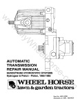
Use the wiring diagrams (see Wiring Diagrams section)
to locate terminals, relays, etc. Figure 4-1 shows some
of the control components for the NB model generator
sets.
Many troubleshooting procedures
IBWARNINZ;) present hazards which can result in
UNIT
NB
MCCK (Spec D)
NH (Spec A through C)
CCK (Spec R)
MCCK (Begin Spec E)
NH (Spec D through F)
BF
CCK (Begin Spec U)
LK (Begin Spec M)
NH (Begin Spec J)
BFA (Spec A)
BGA (Spec A)
NH (Spec K)
severe personal injury, death, and/or equipment
damage. Only qualified service personnel with knowledge of fuels, electricity, and machinery hazards
should perform service procedures. Review safefy
precautions on inside cover page.
PAGE
4-1
4-5
4-9
4-16
I
4-20
RESISTOR R2
SWITCH
SC-1620
FIGURE 4-1. NB GENERATOR SET CONTROL
4-1
Redistribution or publication of this document
by any means, is strictly prohibited.
PROBLEM
A.
B.
C.
D.
E.
_ _ _ ~ _ _
~
SEE PAGE
Engine does not crank.
Engine cranks but does not start.
Engine starts but stops when start switch is released.
Generator set is running then stops.
Low battery no high charge rate.
-
__
-
4-3
4-4
~~
A.
ENGINE DOES NOT CRANK
1.
Check battery. Are battery cables tight?
2.
Is battery voltage present between control TB1 terminal 3 and B+ terminal when
start switch S1 is pushed to “START?”
Batteries present the hazard of explosion, which can result in
IBWARNING]severe personal injury. Because batteries produce explosive gas,
do not smoke or allow any arc-producing devices in the battery area.
3.
Replace start-stop switch S1.
4.
Is battery voltage present between start solenoid terminal S1 and ground when
start switch S1 is pushed to “START?”
5.
Replace start solenoid K1 which is defective.
Perform generator tests. See Generator section.
6
ENGINE CRANKS BUT DOES NOT START
B.
1.
YES
Is battery voltage present between stop relay K2 terminal 5 and a good ground
when start switch is pushed to “START?”
(Open control cover.)
3
Batteries present the hazard of explosion, which can result in
kdo@not%
! lsmoke or allow
severe personal injury. Because batteries produce explosive gas
any-arc producing devices in the battery area
2.
Check wiring to stop relay K2 and connections. Replace stop relay if necessary.
-
3.
Does unit have fuel solenoid?
4
4.
Does fuel solenoid operate when start switch is pressed to “START?”
6
5.
Check wires to fuel solenoid, check solenoid, and replace if necessary.
-
6.
Does generator set have an electric fuel pump?
7
7.
Remove fuel line from carburetor and momentarily jumper control positive terminal
of ignition coil to battery positive post. Does fuel pulsate from fuel line?
9
Fuel presents the hazard of fire or explosion which can cause
k@@@l
severe personal injury or death. Do not permit any flame, spark,
pilot light, cigarette, or other ignition source near the fuel system. Use extreme
care during this test. Run fuel into a suitable container and make sure area is
well-ventilatedto prevent accumulation of explosive gasoline fumes. Keep an
ABC iype fire exiinguisher near.
4-2
Redistribution or publication of this document
by any means, is strictly prohibited.
B.
I ENGINE CRANKS BUT DOES NOT START
a. Check wire lead to fuel pump, check fuel pump, and replace if necessary.
I YES I
NO
YES
NO
See the lgnition System section in the ENGINE portion of the Master Service
Manual (922-0501).
9
ENGINE STARTS BUT STOPS WHEN START SWITCH IS RELEADED
C.
Connect DC voltmeter to start solenoid relay K1 terminal S1, and to a good ground.
Crank the engine until it starts, release start switch and note voltmeter. Did voltmeter indicate a voltage after start switch was released?
1.
Electrical shock can cause severe personal injury or death. Use
extreme caution when working on electrical circuitry. Attach and
remove meter leads only when generator set is not operating. Do not touch meter
or meter leads during testing.
2.
Check wire connections from generator to start solenoid K1 terminal S1. If OK,
perform generator test Generator Troubleshooting and Procedures).
3.
Check resistor R1 and resistor connections. Are they OK?
4.
Replace resistor or wire leads as necessary.
5.
Check reverse current diode CR1 for short or open, and diode connections.
Replace if necessary.
D.
GENERATOR SET IS RUNNING-THEN STOPS
YES
1.
Press start switch S1 to “START”. Did engine start but stop when switch Sl is
released?
1c
2.
Connect a DC voltmeter between stop relay K2 terminal 5 and a good ground.
(Open control cover.) Is battery voltage present when start switch is pushed to
“START?”
38
Jumper stop relay terminals 5 and 11. Crank the engine. Does engine start and
run?
4
Stop the engine. Jumper battery positive to stop relay K2 terminal 9. Does stop
relay operate?
6
-
3.
4.
-
Batteries present the hazard of explosion, which can result in
1 -do not smoke or allow
severe personal injury. Because batteries produce explosive gas,
any arc-producing devices in the battery area.
5.
Replace stop relay K2.
-
6.
Check resistor R1 and resistor connections. Are they OK?
8
7.
Repair wire leads or replace resistor as necessary.
-
8.
Perform generator tests (See Generator Troubleshooting and Procedures).
-
4-3
Redistribution or publication of this document
by any means, is strictly prohibited.
-
E.
LOW BATTERY NO HIGH CHARGE RATE
1.
Jumper two-step voltage regulator relay terminals “BAT” and “B’. Start generator
set. (Open control cover.) Does ammeter indicate higher charge rate?
YES
NO
2
3
Batteries present the hazard of explosion, which can resulf in
laWAR”Gl
severe personal injury. Because batteries produce explosive gas,
do not smoke or allow any arc-producing devices in the battery area.
2.
Replace two-step voltage regulator relay K3.
-
-
3.
Check resistor R2, resistor connections, and replace if necessary.
-
-
4-4
Redistribution or publication of this document
by any means, is strictly prohibited.
MCCK (SPEC D) MODELS AND
NH (SPEC A THROUGH C) MODELS
To correct a problem, answer the question in the
appropriate troubleshooting chart either YES or NO.
Refer to the number in that column and proceed to that
step.
Use the wiring diagrams (see Wiring Diagrams section)
to locate terminals, relays, etc. Figure 4-2 shows some
of the control componentsfor NH generator sets, Spec A
through c.
Many troubleshooting procedures
k%!
!
@
%l
present hazards which can result in
severe personal injury or death. Only qualified service
personnel with knowledge of fuels, electricify, and
machinery hazards should perform service procedures. Review safety precautions on inside cover
page-
RESISTOR R2, rl
/
START-STOP
SWITCH
TERMINAL
,JY I START DISCONNECT
RELAY
SC-1621
FIGURE 4-2. GENERATOR SET CONTROLS, MCCK (SPEC D),
NH (SPEC A THROUGH C)
I
I
I
SEE PAGE
PROBLEM
A. Engine does not crank.
B. Engine cranks but does not start.
C. Engine starts but stops when start switch is released.
D. Engine is running then stops.
E. Low battery no charge rate.
-
-
4-8
~~
A.
ENGINE DOES NOT CRANK
1.
Check battery. Are battery cables tight?
YES
Batteries present the hazard of explosion, which can result in
1 -do not smoke or allow
severe personal injury. Because batteries produce explosive ga!
any arc-producing devices in the battery area.
2.
Connect a DC voltmeter between control terminal 3 and B+ terminal. (Open control
cover.) Is battery voltage present when start switch is pushed to “START?”
Electrical shock can cause severe personal injury or death. Use
IBWARNINF] extreme caution when working on electrical circuitry. Attach and
remove meter leads only when generator set is not operating. Do not touch meter
or meter leads during fesfing.
3.
Replace start-stop switch SI
4-5
Redistribution or publication of this document
by any means, is strictly prohibited.
ENGINE DOES NOT CRANK
Connect the DC voltmeter between terminal 7 of the start disconnect relay assemb
and battery B+ terminal. Is battery voltage present when start switch S1 is pushed t
“START”?
Replace start disconnect relay from start disconnect assembly.
Connect the DC voltmeter to the start solenoid relay terminal S1 and to a good
ground. Is battery voltage present when start switch is pushed to “START”?
Replace start solenoid relay K1.
Perform generator tests. See Generator section.
ENGINE CRANKS BUT DOES NOT START
Connect a DC voltmeter between the control B+ terminal and terminal 9 of the start
disconnect relay assembly. (Open control cover.) Is battery voltage present when
start switch S1 is pushed to “START”?
3
2
Replace the start disconnect printed circuit board.
-
-
Connect a DC voltmeter between control terminal 2 and 1. Is battery voltage
present when the start switch is pushed to “START”?
7
4
Check resistor R3 and resistor connections. Are they OK?
6
5
Repair wire lead connections or replace resistor as required.
-
-
Replace start disconnect relay K4.
-
-
Is the unit an MCCK series generator set?
8
20
Is the red button on the low oil pressure relay K5 out? (Wait at least one minute,
then push in red button.)
9
11
Check oil level. If okay, remove wire lead from low oil pressure switch S4 and push
start switch. Does engine crank and run?
10
11
Check for a grounded wire lead to the low oil pressure switch S4. Check low oil
pressure switch S4 and resistor R4. Replace as necessary.
-
-
Connect the DC voltmeter to stop relay K2 terminal 5 and to a good ground. Is battery voltage present when start switch S1 is pushed to “START”?
13
12
Electrical shock can cause severe personal injury or death. Use
laWAR”Gl
extreme caution when working on electrical circuitry. Attach ani
remove meter leads only when generator set is not operating. Do not touch meter
or meter leads during testing.
Operating the engine with inadequate oil and oil pressure can
1 -oil pressure. Otherwise,
damage or destroy it. Make sure the engine has sufficient oil anr
engine damage will occur.
4-6
Redistribution or publication of this document
by any means, is strictly prohibited.
B.
I ENGINE CRANKS BUT DOES NOT START
12. Check wiring to stop relay K2 and connections. Replace stop relay if necessary.
.
13.
Jumper resistor RT1 terminal with wire lead which goes to low oil pressure relay K
and push start switch S1.Does engine crank and run?
I YES I NO
-
-
14
15
Electrical shock can cause severe’personal injury or death. Use
extreme caution when working on electrical circuitry. Aitach anc
remove jumper leads only when generator set is not operating. Do not touch
jumper leads during testing.
14.
Check low oil pressure relay K5 and replace if necessary.
-
-
15.
Jumper high water temperature switch S3 and push start switch. Does engine cran
and run?
16
17
16.
Check high water temperature switch S3 and wiring. Replace as necessary.
-
17.
Does generator set have a fuel solenoid K6?
18
20
18.
Does fuel solenoid K6 operate when you push start switch S1 to “START”?
20
19
19.
Check wire to fuel solenoid, check fuel pump, and replace if necessary.
-
-
20.
Connect a DC voltmeter to the “+” terminal of the ignition coil and to a good grounc
Is battery voltage present when the start switch S1 is pushed to “START”?
22
21
21.
Check wiring to stop relay K2 and connections. Replace stop relay if necessary.
-
-
22.
Does unit have a low oil pressure switch?
23
27
23.
Check oil level. If okay, remove wire lead from low oil pressure switch and push
start switch. Does engine crank and run?
24
27
Operating the engine with inadequate oil and oil pressure can
damage or destroy if. Make sure the engine has sufficient oil and
oil pressure. Otherwise, engine damage will occur.
24.
Is wire lead from low pressure switch grounded?
25
26
25.
Repair or replace wire lead.
-
-
26.
Check low oil pressure switch and replace if necessary.
-
27.
Does unit have high air temperature switch?
28
32
28.
Remove wire lead from high air temperature switch and push start switch S1. (Do
not let wire lead ground while disconnected). Does engine crank and run?
29
32
29.
Is wire lead from high air temperature switch grounded?
30
31
30.
Repair or replace wire lead.
-
-
31.
:heck high air temperature switch and replace if necessary.
-
-
32. loes qenerator set have an electric fuel pump?
4-7
33 35
Redistribution or publication of this document
by any means, is strictly prohibited.
YES
B.
ENGINE CRANKS BUT DOES NOT START
33.
Remove fuel line from carburetor and jumper momentarily B+ to fuel pump. Does
fuel pulsate from fuel line?
35
Fuel presents the hazard of fire or explosion which can cause
severe personal injury or death. Do not permit any flame, spark,
pilot light, cigarette, or other ignition source near the fuel system. Use extreme
care during this test. Run fuel into a suitable container and make sure area is
well-ventilatedto prevent accumulation of explosive gasoline fumes. Keep an ABC
type fire extinguisher nearby.
34.
Check wire lead to fuel pump, check fuel pump and replace if necessary.
-
35.
See the lgnition System section in the ENGINE portion of the Master Service
Manual (922-0501).
-
C.
ENGINE STARTS BUT STOPS WHEN START SWITCH IS RELEASED
1.
Check resistor R2 and resistor connections in control (open cover). Are they OK?
3
2.
Replace resistor or wire leads as necessary.
-
3.
Check wire connections from generator to start solenoid K1 terminal S1.If OK, perform generator tests (see Generator Troubleshooting and Procedures).
-
D.
ENGINE IS RUNNING THEN STOPS
1.
Check the unit for a high air temperature, high water temperature, or low oil pressure condition (if applicable) which would shut down the engine.
-
YES
-
If no safety shutdown occurred, connect a DC voltmeter to the “IGN” terminal of
control terminal block TI31 (control cover open). Crank the engine. Does engine
start?
NO
YES
-
2
1B
1c
Electrical shock can cause sewere personal injury or death. Use
b!%%@
extreme caution when working on electrical circuitry. Attach and
remove meter leads only when generator set is not operating. Do not touch meter
or meter leads during testing.
2.
Did engine keep running after start switch was released?
3
3.
Recheck for high air temperature, low oil condition, etc., which may have
occurred.
-
E.
LOW BATTERY NO HIGH CHARGE RATE
-
YES
Jumper two-step voltage regulator relay terminals “BAT” and “B.”(Open control
cover.) Start generator set. Does ammeter indicate higher charge rate?
NO
2
Batteries present the hazard of explosion, which can result in
severe personal injury. Because batteries produce explosive gas,
do not smoke or allow any arc-producing devices in the battery area.
Replace two-step voltage regulator relay K3.
Check resistor R1 and resistor connection and replace if necessary.
4-8
-
Redistribution or publication of this document
by any means, is strictly prohibited.
Many troubleshooting procedures
present hazards which can result in
severe personal injury, death, and/or equipment dam-
CCK (SPEC R)
MCCK (BEGIN SPEC E), AND
NH (SPEC D THROUGH F) MODELS
age. Only qualified service personnel with knowledge
-ro correct
a problem, answer the question in the
appropriate troubleshooting either YES or NO. Refer to
the number in that column and proceed to that step.
OffUe/Sye/eCfficifYyandmachineryhazafds shouldper-
form service PrOCdUreS. fieview Safefy precautions
on inside cover page.
Usethe wiring diagram (see Wiring Diagramssection)to
locate terminals, relays, etc. Figure 4-3 shows some of
the control components for NH generator sets, Spec D
through F; CCK generator sets, Spec R; and MCCK
generator sets, begin Spec E (except automatic-starting
MCCK units, described under CONTROL-0-MATIC in
Part 111, Section 5 of the Onan Master Service Manual).
SC-1622
FIGURE 4-3. GENERATOR SET CONTROLS, CCK (SPEC R),
MCCK (BEGIN SPEC E), NH (SPEC D THROUGH F)
~
PROBLEM
’
A. Engine does not crank.
6.Engine cranks but does not start.
i C. Engine starts but stops when start switch is released.
D. Engine is running - then stops.
E. Low battery - no high charge rate.
F. Battery loses excess water.
SEE PAGE
4-10
4-1 1
4-12
4-13
4-13
4-13
I
4-9
Redistribution or publication of this document
by any means, is strictly prohibited.
A.
-
NO
I YES
--
ENGINE DOES NOT CRANK
For generator sets with a three-wire start adapter printed circuit (P.C.) board (below the control P.C.
board) and a remote start-stop station, perform start tests first from the generator set control. If the
generator set starts using the generator set control, the problem lies in the three-wire adapter board or
Ihe remote switch. Check relay K2 of the adapter by jumping terminal 3 to ground. If the relay does not
operate or its contacts do not close to energize the start circuit, replace the board.
2
-
3
5
Jumper between control terminal 16 and start solenoid terminal K1-S. Press start
switch A1S1. Does engine crank?
4
5
4.
Replace start disconnect adapter P.C. board.
-
-
5.
Push “Hand Crank” ELECTRIC (called “ROPE START“ or “NONFUNCTIONAL” on
some models) switch AlS1. Is battery voltage present between control terminal 6
and ground?
9
6
Remove control cover and jumper terminal 5 to terminal 6. Is battery voltage presen
between terminal 6 and ground?
7
8
-
-
1.
Check battery. Are battery cables tight?
Batteries present the hazard of explosion, which can result in
severe personal injury. Because batteries produce explosive gas
do not smoke or allow any arc-producing devices in the battery
area.
2.
Does generator set have a start disconnect adapter P.C. board below the generator set control assembly P.C. board (don’t confuse this board with a three-wire
adapter, P.C. board on some models which has a terminal block).
For marine applications, be sure bilge blower has operated and
@
@
%
!
I
time delay (if applicable) on start has completed. Otherwise,
fhere is potential danger of explosion or fire from fuel vapors.
3.
6.
Electrical shock can cause severe personal injury or death. Use
[BWARNINGI
extreme caution when working on electrical circuitry. Attach anc
remove meter leads only when generator set is not operating. Do
not touch meter or meter leads during testing.
7.
Replace switch A1S1.
8.
Check battery cables for correct polarity. Replace fuse F1 with a 9-ampere, in-line
fuse. Push start switch AlS2.
9.
10.
9
With start switch A I S2 depressed, is at least 8 volts present from terminal 9 to
ground?
10
14
Jumper solenoid coil terminal S to battery. Does start solenoid K1 operate?
11
12
-
4-1 0
Redistribution or publication of this document
by any means, is strictly prohibited.
A.
11.
ENGINE DOES NOT CRANK
Is battery voltage present from right-hand terminal of start solenoid to ground wher
start solenoid is energized?
12.
Start solenoid is defective and must be replaced.
13.
Perform generator tests. See Generator section.
14.
Is voltage present from terminal 15,17, or 18 to ground?
15.
With start switch A1S2 depressed, jumper terminal 5 to terminal 1517 or 18. Does
engine crank and start?
16.
Remove control P.C. board. Replace A1 F2 fuse path with a one-inch (25 mm) lengtl
of number 22 wire. Solder in place through holes provided.
17.
Jumper control terminal 5 to 16. Does engine crank?
18.
Replace start switch A1S2.
19.
With start switch A1S2 depressed, jumper control terminals 9 to 16. Does engine
crank?
20.
Check transistor AlQ2. If defective, replace control P.C. board.
6.
ENGINE CRANKS BUT DOES NOT START
1.
Is battery voltage present between control terminal 6 and ground when start switch
A1S2 is depressed?
YES
4
2
Is battery voltage present between control terminal 6 and ground when switch AIS’
is depressed?
3
-
3.
Faulty switch A I S1 or diode A1CR1. Replace control P.C. board.
-
-
4.
Is operation with gasoline?
9
5
5.
Does gaseous fuel solenoid operate when switch AIS1 is pressed?
15
6
6.
Jumper terminal “VALVE” of gaseous vacuum switch (on intake manifold) to contrc
terminal 6. Does fuel solenoid operate when switch A1Sl is pressed?
7
8
7.
Check wire leads to vacuum switch, check switch and replace if necessary.
-
-
8.
Check wire leads to gaseous fuel solenoid, check solenoid and replace if
necessary.
-
-
9.
Does generator set have an electric fuel pump?
10
15
IO.
Does generator set have a gasoline shutoff solenoid?
11
13
11.
Fuel solenoid must open during cranking and running. Remove the fuel line from
carburetor and push switch AlSl. Does fuel pulsate from fuel line?
15
12
Electrical shock can cause severe personal injury or death. Use
extreme caution when working on electrical circuitry. Attach ani
remove meter leads only when generator set is not operating. Do not touch meter
or meter leads during testing.
2.
4-1 1
Redistribution or publication of this document
by any means, is strictly prohibited.
B.
Fuel presents the hazard of fire or explosion which can cause
severe personal injury or death. Do not permit any flame, spark,
pilot light, cigarette, or other ignition source near the fuel system. Use extreme
care during this test. Run fuel into a suitable container and make sure area is
well-ventilated to prevent accumulation of explosive gasoline fumes. Keep an ABC
fype fire extinguisher nearby.
Remove the fuel solenoid from the fuel line. Push switch A1S1. Does fuel pulsate
from the line?
14
13
13.
Check wire lead to fuel pump, check fuel pump and replace if necessary.
-
-
14.
Check wire leads to gasoline solenoid, check solenoid and replace if necessary.
-
-
15.
Check oil level. If okay, remove wire lead for low oil pressure switch S1 from control
16
terminal 4 and push start switch AlS2. Does engine crank and run?
19
12.
Operating the engine with inadequate oil and oil pressure can
koil@pressure.
@
! l Otherwise,
damage or destroy it. Make sure the engine has sufficient oil and
engine damage will occur.
16.
Is wire lead from low oil pressure switch grounded?
17
18
17.
Repair or replace wire lead.
-
-
18
Check low oil pressure switch S1 and replace if necessary.
-
-
19.
Is unit water-cooled and does it have a high water temperature switch?
20
22
20.
Jumper across high water temperature switch and push start switch A1 S2.Does
engine crank and run?
21
27
21.
Check high water temperature switch and replace if necessary.
-
-
22.
Is unit air cooled and have a high air temperature switch?
23
27
23.
Remove wire lead from high air temperature switch from control terminal 3 and
push start switch AlS2. Does engine crank and run?
24
27
24.
Is wire lead from high air temperature switch grounded?
25
26
25.
Repair or replace wire lead.
-
-
26.
Check high air temperature switch and replace if necessary.
-
-
27.
See the Ignition System section.
-
-
C.
ENGINE STARTS BUT STOPS WHEN START SWITCH IS RELEASED
YES
NO
1.
Connect voltmeter from control terminal 8 to ground. Crank engine. Is there DC voltage output from generator?
3
2
--
Electrical shock can cause severe personal injury or death. Use
extreme caution when working on electrical circuitry, Attach and
remove meter leads only when generator set is not operating. Do not touch meter
or meter leads during fesfing.
4-12
Redistribution or publication of this document
by any means, is strictly prohibited.
ENGINE STARTS BUT STOPS WHEN START SWITCH IS RELEASED
C.
2. Check resistor G1R11 and all resistor connections.
3.
Is voltage present from terminal 6 to ground after engine starts and start switch
A1 S2 is released?
4.
D.
1.
Replace control P.C. board.
-
ENGINE IS RUNNING THEN STOPS
Check the unit for a high air temperature, high water temperature or low oil condition (if applicable) which would shut down unit.
If no safety shutdown occurred, connect a DC voltmeter from control terminal 8 to
ground. Crank the engine. Is there generator DC output voltage?
2.
-
Check resistor G1R11 and all resistor connections. If OK, perform generator tests
(Generator Troubleshootingand Procedures).
-
E.
LOW BATTERY NO HIGH CHARGE RATE
1.
Remove wire lead from fuse F1 to control terminal 5. Connect DC ammeter betweer
wire lead and terminal 5. Start generator set. Is high battery charge rate present
(over 3 amperes)?
2.
Measure battery terminal voltage with voltmeter (one percent accuracy or better).
Does voltage rise to 14 volts or more?
-
Batteries present the hazard of explosion, which can result in
severe personal injury. Because batteries produce explosive gat
do not smoke or allow any arc-producing devices in the battery area.
Electrical shock can cause severe personal injury or death. Use
extreme caution when working on electrical circuitry. Attach ant
remove meter leads only when generator set is not operating. Do not touch mete
or meter leads during testing.
3.
Remove control cover and jumper control terminals 7 and 8. Does charge rate
increase?
4.
Check battery and replace if necessary.
5.
Stop generator set. Check wire leads to charge resistor G1 R1. Check resistor and
replace if necessary.
6.
Replace control P.C. board.
F.
BATTERY LOSES EXCESS WATER
1.
Connect a voltmeter (one percent accuracy or better) to battery terminals, start and
run generator set for 30 minutes. Does battery terminal voltage exceed:
a. 14 volts at 100°F (38°C) or above; or
b. 15 volts at 50 to 100°F (10 to 38°C); or
c. 16 volts at 50°F (10OC) or below?
Electrical shock can cause severe personal injury or death. Use
(BWARNINGI extreme caufion when working on electrical circuifry. Attach anc
remove meter leads only when generator set is not operating. Do not touch meter
or meter leads during testing.
2.
Replace control P.C. board.
4-1 3
Redistribution or publication of this document
by any means, is strictly prohibited.
SYMPTOM:
Engine won’t start and electric fuel pump won’t work unless hand crank switch AIS1 is pushed
during cranking. Engine runs okay after starting with hand crank switch.
PROBLEM:
Diode AlCR1 is destroyed through accidental grounding of terminal 6 or the leads supplying
current to the ignition coil, electric fuel pump or fuel solenoid when start switch closes.
SOLUTION:
To prevent future failure of diode A1 CR1 on units without 9-ampere fuse on terminal 5, add in-line
fuse package #321-0212. Refer to Product Support Bulletin #57.
SYMPTOM:
Engine stops running as soon as start switch is released.
PROBLEM:
Diode A1 CR2 is destroyed through accidentalgrounding of terminal 6 or the leads supplying current
to the ignition coil, electric fuel pump or fuel solenoid, while engine is running.
SOLUTION:
To prevent future failure of diode A1CR2 on units without 9-ampere fuse on terminal 5, add inline
fuse package #321-0212. Refer to Product Support Bulletin #57.The fuse does not protect A1CR2,
but will blow during cranking if terminal 6 is grounded.
~
~____
~~~~
SYMPTOM:
~
___
~
~
~
~
~~
Start solenoid will not energize (check for faulty solenoid before checking following).
1. PROBLEM:
Diode AlCR4 may be burned out if battery connections are accidentally reversed on units not
protected by 9-ampere fuse F1 on terminal 5.
SOLUTION:
To prevent future failure of diode A1 CR4 on units without 9-ampere fuse on terminal 5, add inline
fuse package #321-0212. Refer to Product Support Bulletin #57.
2. PROBLEM:
Accidental reverse battery connectionto units not protected by in-line fuse package#321-0212may
damage diode AlCR5.
SOLUTION:
To prevent future failure of diode AlCR5 on units without 9-ampere fuse on terminal 5,add in-line
fuse package #321-0212. Refer to Product Support Bulletin #57.
Controls Without Start Disconnect Adapter
SYMPTOM:
Start solenoid won’t energize.
PROBLEM:
On units without 9-ampere fuse on terminal 5, accidental grounding of terminal 9or reverse battery
connections may damage transistor A1Q2.
SOLUTION:
To prevent future failure of transistor AlQ2, on units without 9-ampere in-line fuse on terminal 5,
install in-line fuse package #321-0212. Refer to Product Support Bulletin #57.
SYMPTOM:
Engine cranks but will not start (no battery voltage at terminal 6).
PROBLEM:
Ashort circuit or accidental ground on terminal 6 may burn the copper path from terminal 6 toAlS1
when start switch is pushed and/or burn the copper path from terminal 5 to A1S1 if handcrank
switch is pushed.
SOLUTION:
To prevent future burning of copper path, on units not having 9-ampere fuse on terminal 5, add
in-line fuse package #321-0212. Refer to Product Support Bulletin #57.
SYMPTOMS:
1. Engine won’t crank. F1 or A1F2 open.
2. Remote running time meter or generating lamp won’t work. A1F3 fuse open.
PROBLEM:
On units not having a 9-ampere fuse protection on terminal 5, customer wiring errors including
reverse battery connections, causes A1 F2 and A1 F3 to blow.
SOLUTION:
F1-On units not having a 9-ampere in-line, F1 fuse protection, solder a wire in place of A1 F1 fuse
link on printed circuit board (wire size not important). Add in-line fuse package #321-0212. Refer to
Product Support Bulletin #57.
4-14
,
Redistribution or publication of this document
by any means, is strictly prohibited.
GENERAL CONTROL P.C. BOARD PROBLEMS AND SYMPTOMS (Continued)
A1 F2-On units not having a 9-ampere fuse protection on terminal 5, install insulated jumper wire
from TB2-18 to TB1-5. Add in-line fuse package#321-0212. Refer to Product Support Bulletin #57.
A1 F3-Connect bypass fuse assembly #321-0210 between TB1-2 and TB2-10. Refer to Product
Support Bulletin #40.
SYMPTOM:
Engine won't stop on low oil pressure or may not stop with stop watch.
PROBLEM:
Customer wiring errors which place battery voltage on terminal 14 destroys diode AlCR8 and/or
copper path from terminal 4 through switch A1S2 and AlCR8 (may also destroy copper path from
terminal 1 to 14).
SOLUTION:
Correct the problem (wiring, etc.). To prevent future failure of diode A I CR8 or burnt copper paths,
install in-line fuse package#321-0212. Older units havingfuse link A1 F1 on the printed circuit board
may also have blown. Replace A1F1 fuse link with jumper wire.
SYMPTOM:
Engine won't stop with stop switch pushed or from low oil pressure.
PROBLEM:
On units without 9-ampere fuse on terminal 5, accidentalconnectionof battery positive voltage from
terminal 15 or 16 to terminal 14, burns one of the following copper paths.
Path
Path
Path
Path
from
from
from
from
terminal
terminal
terminal
terminal
1 to 14.
4 to switch AlS1.
12 to switch AlS1.
14 to diode AlCR8.
SOLUTION:
To prevent future burning out of copper paths, on units without9-ampere fuseon terminal 5, add the
in-line fuse package #321-0212. Refer to Product Support Bulletin #57.
SYMPTOMS:
Excessive current overheats and destroys diode AlCRlO and copper path from AlCR10 to
terminal 2.
PROBLEM:
There are three known causes of excessive currents which may cause this problem.
1. Reverse battery connections on units not having the 9-ampere in-line fuse F1 and diode
A i CR11 protection.
2. Improper transfer switch that may connect AC utility power to the generator output while
transferring from utility to generator power. See Product Support Bulletin #58.
3. Starting solenoid chatter or sticking solenoid at high cranking current causes current surges
beyond the thermal capability of diode AlCRlO.
SOLUTION:
To prevent future failure of diode AlCRlO on units without a 9-ampere fuse on terminal 5 for
symptoms 1 and 2 above, add in-line fuse package #321-0212. Refer to Product Support Bulletins
#57 and #58.
To preventfuture failureofdiode AlCRlOdueto start solenoid chatterorstickingforsymptom 30n
units without a start disconnect adapter, add a start disconnect package #300-1231.
.
PROBLEM:
AIS1 push button and A1S1 spring can snap off if care is not used in removing cover.
SOLUTION:
Install cover and switch repair package (part #300-1232) which contains all necessary hardware
and parts to repair a missing switch push buttonor spring. This means it is not necessary to replace
the complete printed circuit board unless the entire switch itself becomes broken. In order to prevent
either problem, exercise greater care when removing the printed circuit board cover. Refer to
Product Support Bulletin #57.
Corroded or burned printed circuit parts can and should be repaired by soldering a piece of #20 gauge or larger
insulated wire between soldered connections on the printed circuit board. Soldering on the printed circuit paths
themselves on the bottom of the board is difficult and should be avoided.
In some cases a jumper wire can be connected between terminals on the terminal strips.
4-15
Redistribution or publication of this document
by any means, is strictly prohibited.
BF, CCK (BEGIN SPEC U),
LK (BEGIN SPEC M), AND
NH (BEGIN SPEC J) MODELS
FUSES F1 AND F2
r
I.
To correct a problem, answer the question in the
appropriate troubleshooting chart either YES or NO.
Refer to the number in that column and proceed to that
step.
CRANK IGNITION
Use the wiring diagrams (see Wiring Diagrams section)
to locate terminals, relays, etc. Figure 4-4 shows some
of the control components for these generator sets.
Many troubleshooting procedures
present hazards which can result in
severe personal injury, death, and/or equipment damage. Only qualified service personnel with knowledge
of fuels, electricity, and machinery hazards shouldperform service procedures. Review safety precautions
on inside cover page.
SC-1623
FIGURE 4-4. GENERATOR SET CONTROLS, BF, CCK
(BEGIN SPEC U), LK (BEGIN SPEC M), NH (BEGIN SPEC J)
PROBLEM
A. Engine does not crank.
8. Engine cranks but does not start
C. Engine starts but stops when start switch is released.
D. Engine is running -then stops.
E. Low battery - no charge rate.
F. Running time meter inoperative.
G. Battery condition meter inoperative.
I
SEEPAGE
4-16
4-17
4-18
4-18
4-18
4-18
4-19
~
A.
ENGINE DOES NOT CRANK
1.
Check battery. Are battery cables tight?
YES
-
2
Batteries present the hazard 01 explosion, which can result in
severe personal injury. Because batteries produce explosive gas,
do not smoke or allow any arc-producing devices in the battery area.
2.
Is battery voltage present between control terminal 3 and 5 when switch S1 is
pushed to “START?”
4
Electrical shock can cause severe personal injury or death. Use
extreme caution when working on electrical circuitry. Attach and
remove meter leads only when generator set is not operating. Do not touch meter
or meter leads during testing.
4-1 6
Redistribution or publication of this document
by any means, is strictly prohibited.
ENGINE DOES NOT CRANK
A.
3. Replace start-stop switch S1.
4.
Is battery voltage present between start solenoid K1 terminal S1 and ground when
start switch is pushed to “START?”
5.
Replace start solenoid.
6.
Perform generator tests. See Generator section.
B.
1.
ENGINE CRANKS BUT DOES NOT START
Is battery voltage present at control terminal 6 and ground when start switch S1 is
pushed to “START?”
2.
Is fuse F2 in circuit to control terminal 6 “blown?”
3.
Replace fuse.
4.
Make sure Faston terminals are making good connections. If OK, replace defective
start solenoid on 4.0 BF (Spec A) or crank ignition relay K2 on 2.5 LK (Spec M), 4.0
BF (Spec B),CCK (Spec U), and NH (Spec J).
5.
Fuel solenoid must open during cranking and running. Remove the fuel line from
carburetor and momentarily jumper control terminal 5 to 6. Does fuel pulsate from
fuel line?
Fuel presents the hazard of fire or explosion which can cause
IBWAR”G( severe personal injury or death. Do not permit any flame, spark,
pilot light, cigarette, or other ignition source near the fuel system. Use extreme
care during this test. Run fuel into a suitable container and make sure area is
well-ventilated to prevent accumulation of explosive gasoline fumes. Keep an
ABC type fire extinguisher nearby.
6.
Check wire lead to fuel pump. Check fuel pump and replace if necessary.
7.
Does engine have oil pump and full pressure lubrication?
8.
Check oil level. If okay, remove wire lead from low oil pressure switch and push
start swtich. Does engine crank and run?
Operating the engine with inadequate oil and oil pressure can
damage or destroy it. Make sure the engine has sufficient oil
and oil pressure. Otherwise, engine damage will occur.
9.
Is wire lead from low oil pressure switch grounded?
10.
Repair or replace wire lead.
11.
Check low oil pressure switch and replace if necessary.
12.
Does unit have a high air temperature switch?
4-1 7
Redistribution or publication of this document
by any means, is strictly prohibited.
B.
I ENGINE CRANKS BUT DOES NOT START
13.
Remove wire lead from high air temperature switch and push start switch S1
(do not let wire lead ground while disconnected). Does engine crank and run?
14.
Is wire lead from high air temperature switch grounded.?
15.
Repair or replace wire lead.
16.
Check high air temperature switch and replace if necessary
17.
See the Ignition System section.
C.
ENGINE STARTS BUT STOPS WHEN START SWITCH IS RELEASED
1.
Connect DC voltmeter from control terminal 6 to ground. Crank engine. Is there DC
voltage output from generator (fuse F2 should be OK if unit started initially)?
Electrical shock can cause severe personal injury or death.
Use extreme caution when working on electrical circuitry.
Attach and remove meter leads only when generator set is not operating. Do not
touch mefer or meter leads during tesfing.
2.
Check resistor R1 and resistor connections. If OK, perform generator tests (see
Generator Troubleshootingand Procedures).
D.
ENGINE IS RUNNING THEN STOPS
1.
Check the unit for a high air temperature, or high water temperature (whichever
applies) or low oil pressure condition which would shut down the engine.
-
If no safety shutdown has occurred, connect a DC voltmeter from control terminal
6 to ground. Crank the engine. Is there DC generator output voltage?
2.
Is fuse F2 in circuit to control terminal 6 “blown?”
3.
Replace fuse.
4.
Check resistor R1 and all resistor connections. If OK, perform generator tests. See
Generator Troubleshooting and Procedures.
E.
LOW BATTERY NO CHARGE RATE
1.
Is reverse current diode CRI shorted or open?
2.
Replace diode.
3.
Check wiring from diode CR1 to start solenoid and to battery.
F.
RUNNING TIME METER INOPERATIVE
1.
Check wires between control terminal 6 and battery positive terminal for running
time meter, and ground wire and connection to meter. Does this correct the
problem?
2.
Replace defective running time meter.
-
4-1 8
Redistribution or publication of this document
by any means, is strictly prohibited.
BATTERY CONDITION METER INOPERATIVE
YES
NO
Is fuse F1 “blown?”
2
3
Replace fuse with equivalent type fuse.
-
-
Check wires between control terminal 5 and battery positive terminal for battery
condition meter terminal and ground wire and connection to meter. Does this
correct problem?
-
4
Replace defective battery condition meter.
-
-
4-1 9
Redistribution or publication of this document
by any means, is strictly prohibited.
step.
Use the wiring diagrams (see Wiring Diagrams section)
for location of terminals, relays etc. Figure 4-5 shows
some of the control components for the generator sets.
procedures. Review safety precautions on inside cover
page-
J
-
C0NTR0L
BOX
FEED-THROUGH
k
OIL PRESSURE SWITCH)
REVERSE CURRENT
CRANK IGNlTiON
RELAY K2
START-STOP
SWITCH S1
FUSE F1-
NOTE CONTROL PANEL
SHOWNROTATED90”
TO ENABLEILLUSTRATION
OF CONTROLCOMPONENTS.
@
FUELF2
SC-1624
FIGURE 4-5. GENERATOR SET CONTROLS,
BFA, BGA, NH (SPEC K)
PROBLEM
I SEEPAGE
A. Engine does not crank.
B. Engine cranks but does not start.
C. Engine starts but stops when start switch is released.
1 D. Engine is running then stops.
E. Low battery - no charge rate.
F. Running time meter inoperative.
G. Battery condition meter inoperative.
-
4-20
Redistribution or publication of this document
by any means, is strictly prohibited.
A.
ENGINE DOES NOT CRANK
1.
Check battery. Are battery cables tight?
~
~~
Batteries present the hazard of explosion, which can result in
severe personal injury. Because batteries produce explosive gas
do not smoke or allow any arc-producing devices in the battery area.
2.
Is battery voltage present between control remote connector plug terminals 3 and 5
(or between TB1-3 and TB1-5 where applicable) when start-stop switch S1 is
pushed to “START?” (See drawing of connector plug in Figure D.)
Electrical shock can cause severe personal injury or death. Use
extreme caution when working on electrical circuitry. Attach and
remove meter leads only when generator set is not operating. Do not touch meter
or meter leads during testing.
3.
Replace start-stop switch S1.
4.
Is battery voltage present between start solenoid K1 terminal S1 and ground when
start switch is pushed to “ON?”
5.
Replace start solenoid.
6.
Perform generator tests. See Generator section.
B.
ENGINE CRANKS BUT DOES NOT START
1.
Is 5-ampere fuse F2 blown?
2.
Replace fuse.
3.
Is battery voltage present between control remote connector plug terminal 6 (or
terminal TB1-6 where applicable) and ground when start-stop switch SI is pushed
to “START?” (Figure D shows locations of connector plug terminals.)
4.
Make sure Faston terminals are making good connections to crank ignition relay
K2. If OK, replace crank ignition relay.
5.
Disconnect B+ wire from ignition coil. Remove the fuel line from the carburetor,
connect a flexible hose long enough to run fuel in a suitable container. Momentarill
push start-stop switch to “START.” Does fuel pulsate into container? (Reconnect
line and wire to ignition coil after test.)
Fuel presents the hazard of fire or explosion which can cause
severe personal injury or death. Do not permit any flame, spark,
pilot light, cigarette, or other ignition source near the fuel system. Use extreme
care during this test. Run fuel into a suitable container and make sure area is
well-ventilated to prevent accumulation of explosive gasoline fumes. Keep an
ABC type fire extinguisher nearby.
4-21
Redistribution or publication of this document
by any means, is strictly prohibited.
B.
ENGINE CRANKS BUT DOES NOT START
6.
Check lead to fuel pump. Check fuel element to see if it needs cleaning. Replace
fuel pump if necessary.
7.
See the Ignition System section.
C.
ENGINE STARTS BUT STOPS WHEN START SWITCH IS RELEASED
1.
Is engine oil level OK?
2.
Add oil as needed.
3.
Remove cover from control assembly. Are resistor R1 (120-ohm) and resistor connections OK (located near bottom of control).?
4.
Remedy or replace as needed.
5.
If oil level was OK in Step 1, pull apart feed-through connector (shown in Figure
4-5) in control from run ignition relay K3 and connect lead from K3 to a good
ground. Push start switch. Does engine crank and run?
~
~
~~
1-
Operating the engine with inadequate oil and oil pressure can
damage or destroy it. Make sure the engine has sufficient oil and
oil pressure. Otherwise, engine damage will occur.
6.
Stop engine and reconnect feed-through connector. Check low oil pressure
switch, check lead to low oil pressure switch and repair or replace as needed.
7.
Reconnect feed-through connector in control, jumper remote connector plug terminals 5 and 6 (or terminals TB1-5 and TB1-6 if applicable), and push start switch
S i to “START” (fuse F1 must be OK for this test). Does engine crank and run?
(Figure 4-5 shows locations of connector plug terminals.)
8.
With engine running, is there 12 VDC from remote connector plug terminal 2 (or
terminal block terminal TB1-2) to ground?
9.
Replace run ignition relay K3.
10.
See Generator Troubleshooting and Procedures.
D.
GENERATOR SET IS RUNNING-THEN STOPS
Is there fuel in the fuel tank?
Does engine have a low oil level (pressure)condition?
Refill oil to proper oil level.
See “ENGINE STARTS BUT STOPS WHEN START SWITCH IS RELEASED‘ in
Troubleshooting.
E.
LOW BATTERY-NO CHARGE RATE
1
Is reverse current diode CR1 shorted or open?
2.
Replace diode.
3.
Is wiring from reverse current diode to battery OK?
4.
Remedy as necessary.
NO
4-22
,
Redistribution or publication of this document
by any means, is strictly prohibited.
,
1 YES
E.
LOW BATTERY-NO
7.
Remove wrapper from around the generator. Is resistor R2 and are resistor
connections OK?
7
6.
Remedy or replace as necessary.
-
7.
See Generator Troubleshooting and Procedures.
-
F.
RUNNING TIME METER INOPERATIVE
1.
Check wires between control remote connector plug terminal 6 (or TBl-6 where
applicable) and battery positive terminal for running time meter, and ground wire
and connection to meter. Does this correct problem? (Figure 4-5 shows locations of
connector plug terminals.)
2.
Replace defective running time meter.
G.
BATTERY CONDITION METER INOPERATIVE
1.
Is fuse F1 “blown?”
2
2.
Replace fuse with equivalent type fuse.
-
3.
Check wires between control remote connector plug terminal 5 (or TB1-5 where
applicable) and battery positive terminal for battery condition meter terminal and
ground wire and connection to meter. Does this correct problem? (Figure 4-5
shows locations of connector plug terminals.)
-
Replace defective battery condition meter.
-
4.
CHARGE RATE
YES
YES
I
4-23
Redistribution or publication of this document
by any means, is strictly prohibited.
,
Redistribution or publication of this document
by any means, is strictly prohibited.
Section 5. Power Drawer Models
GENERATOR DISASSEMBLY
The generator used in the Power Drawer genset normally needs little care, otherthan a periodiccheck of the
brushes and collector rings. If a major repair is necessary, have the genset checked and tested by an Onan
service technician or a qualified electrician.
Many troubleshooting procedures
lnWAR"Gl
present hazards which can result in
severe personal injuryydeath, and/or equipment damage. Only qualified servicepersonnel with knowledge
of fuels, electricityyand machineryhazards shouldperform service procedures. Review safety precautions
on inside cover page.
1.
2.
3.
4.
Remove the unit from its slide rails.
Remove all accessories attached to the generator.
Tag and remove all leads.
Loosen and lift out both brush rigs (Figure 5-1).
The brushes will be damaged
during disassembly if not held
off the slip rings. Use extreme care whenremoving
the brush rigs.
5. Remove four generator through-stud nuts.
6. Lift or pull the end bell from the frame assembly. Do
not pry it loose with a screwdriver; rather, tap
around the edges of the end bell with a plastic
hammer to loosen it.
5-1
Striking the end bell or other
lliEEEl
generator parts can damage or
destroy them. Use extreme care while tapping the
edges of the end bell to loosen it.
7. Remove the frame (field) assembly, being careful
not to let it rest or drag on the armature.
The generator will overheat if it
k%%!
@
l
is reassembled incorrectly. Four
seals are used between the frame (field) assembly
and engine-to-generator adapter. These seals
must be used to reassemble the generator
correctly8. Insert a square 3/8 inch drive into the 12-point
(internal wrenching) armature holddown nut to
remove it.
9. While pulling outward with one hand under the
armature, strike a sharp blow on the end of the
armature shaft to loosen the armature. The armature
has an internal taper which fits onto the external
taper of the engine adapter. If the armature does not
come loose, place a heavy brass rod on the armature shaft near the ball bearing and strike a sharp
downward blow on the rod with a hammer. Rotate
the armature 112 turn before repeating.
Striking the collector rings or
bearing can severely damage or
destroy them. Use extreme care when performing
the procedure described above.
Redistribution or publication of this document
by any means, is strictly prohibited.
GENERATOR-TOADAPTER SEALS
ARMATURE (ROTOR)
THROUGH-STUD
U I
R
vu
B-
FRAMEANDSTATOR
IYUI
/
/
GROMMET FOR
OUTPUT LEADS
GENERATOR
AIR DUCTS
GENERATOR
MOUNTING
STUDS
6-1219
FIGURE 5-1. EXPLODED VIEW OF AC GENERATOR
GENERATOR TROUBLESHOOTING GUIDE
-
Many troubleshooting procedures
present hazards which can result in
severe personal injury or death. On/yqualified service
personnel with knowledge of fuels, electricity, and
ma chin ery hazards sh ould perform service
procedures. Review safetyprecautions on inside cover
page.
Electrical shock can cause severe
lextreme
aWAR"G1
personal injury or death. Use
caution when working on electrical circuitry.
Attach and remove meter leads only when generator
set is not operating. Do not touch meter or meter leads
during testing.
Thebrushes are easily damaged dur@%!!@I
ing genset disassembly/assembly.
Use extreme care whileinsfalling/removingthe genset
Fuel presents the hazard of fire or
explosion which can cause severe
personal injury or death. Do not permit any flame,
spark, pilot light, cigarette, or oiher ignition source
near the fuel system. Keep an ABC type fire extinguisher nearby.
[BWARNINGI
brushes.
Continuous generator set overloading can cause high operating temperatures that could damage the generator windings.
Keep the load within the nameplate rating.
Arcing or inadvertenf starting of the
(BWARNINGI generator set can cause damage to
the generator set, severepersonal injury, or death. For
this reason, disconnect the negative f-) battery cable
beiore beginning these procedures, and do not reconnect the negative (-) battery cable until these procedures are complete.
5-2
Redistribution or publication of this document
by any means, is strictly prohibited.
POSSIBLE CAUSE
TROUBLE
NO AC OUTPUT
I
CORRECTIVE ACTION
1. Blown fuse or circuit breaker.
1. Look for cause and repair. Then
replace fuse or reset circuit breaker.
2. Disconnected wire or lead on
2. Reconnect wire or wires.
VOLTAGE
brushes, bridge rectifier or
reactor assembly.
3. Brushes not making contact with
collector ring.
3. Check brush springs for
free movement or brushes which
may be excessively worn.
4. Open, grounded or
4. Test with tester or
short circuit in field
or armature winding.
ohmmeter and replace if
defective.
5. Defective bridge
rectifier assembly.
5. Test with ohmmeter and
replace if defective.
6. Bridge rectifier
assembly installed
wrong in its case.
6. Reinstall making sure
marks on case and rectifier
match.
LIGHTS FLICKER
INTERMITTENTLY
1. Loose or broken lead/
1. Repair broken lead or
LOW AC OUTPUT
VOLTAGE
1. External short circuit
on line.
.reconnect loose lead.
leads in generator.
NOISY GENERATOR
K c a t e and iiminate s h o r t
circuit problem.
2. Generator overloaded.
2. Remove part of load.
3. Shorted or grounded
circuit in field or
armature winding.
3. Test with ohmmeter or
tester and replace
if defective.
4. Engine not running
properly causing generator
to slow down.
4. Refer to Engine Troubleshooting
guide.
1. Defective bearing in
1. Replace bearing.
end ball.
~
GENERATOR
OVERHEATS
~~~~
1. Generator overloaded.
1. Remove part of load.
2. Windings and parts
2. Clean generator.
covered with oil or dirt.
AC OUTPUT VOLTAGE
HIGH WITH NO LOAD
CONNECTED AND
GENERATOR RUNNING
AT 1800 RPM
3. Air intake restricted
or incoming air too hot.
3. Take necessary steps to
allow for proper cooling.
4. Shorted or grounded
circuit in armature
or field windings.
4. Test with ohmmeter or
tester and replace
if defective.
1. Compounding reactor
1. Remove, test and replace.
5-3
Redistribution or publication of this document
by any means, is strictly prohibited.
GENERATOR SERVICE PROCEDURES
AND TESTS
BRUSH REMOVAL AND REPLACEMENT
To reach the brushes, remove the plastic end bell
screens. (See Figure 5-1 for location of generator components.) Measure brush wear as shown in Figure 5-2,
by inserting a small, narrow scale into the top of the
brush block. If the brushes need replacing, remove and
tag the wires connected to the brush blocks. Then
removethe brush blocks and lift them out of the end bell.
Pull the brushes and springs out from the bottom of the
brush block. Clean the brush block at this time.
The brushes are easily damaged during genset disassembly/assembly.
Use extreme care while installing/removingthe genset
brushes.
New brushes are shaped to fit, and seldom need sanding to seat properly. Always replace brushes as a set,
and use only the correct brushes. Never use asubstitute
brush, which may appear to be the same, but have
different electrical characteristics.
Note that brush blocks are stamped “BRG END” on one
side. Be sure that this stamped side faces the bearing
end of the generator for correct brush alignment.
Tighten the brush block screws to 40 to 70 in.lb or 4 to 6
ft.lb (5 to 8 Nom). If sparking occurs after replacing the
brushes, run the generator with a light load until they
seat properly. Check the brush springs for freedom of
movement.
1
’
ARMATURE GROUND TEST
While the armature is removed for checking shorts
using a growler, additional checks can be made. If the
armature is still installed,liftthe brushes before conducting these tests. These tests use either the continuity
tester buzzer or the test light.
Place one test prod on one of the collector rings and the
other test prod on the armature shaft (Figure 5-3). The
tester buzzer should not buzz(lampshou1dnot light). If it
buzzes (or lights), the AC winding or a collector ring is
grounded to the shaft. Test each collector “ring” in this
manner.
TOP VIEW OF
BRUSH BLOCK
MAXIMUM WEAR
LIMIT ONE INCH
mm) c
CROSS SECTION OF
BRUSH
NOTE:
BRUSH BLOCK
LOCATION
REPLACEWHEN WORN
TO THIS DIMENSION, OR
IF MEASUREMENT“A”
EXCEEDS ONE INCH (25 mm)
MEASURE FROM TOP FACE OF
BRUSH BLOCK TO TOP OF BRUSH
6-1220
FIGURE 5-2. BRUSH WEAR LIMITS
5-4
Redistribution or publication of this document
by any means, is strictly prohibited.
Electrical shock can cause severe
or death. Use
extreme caution when working on electrical circuitry.
Attach and remove meter leads only when the generator set is not operating. Do not touchthe meter or meter
leads during testing.
(BWARNINGI personal injury
6-1222
FIGURE 5-4. ARMATURE OPEN TEST
TESTING FIELD WINDINGS FOR GROUNDS
6-1221
FIGURE 5-3.ARMATURE GROUND TEST
Before testing, disconnect all field leads. Touch one test
prod to F1 (+) and the other prod to the frame (Figure
5-5). The buzzer should not sound or the lamp should
not light. If the tester buzzes or lights, the field is
grounded, and must be replaced. Test lead F2 (-) in the
same manner.
ARMATURE OPEN TEST
Place one test prod on each collector ring (Figure 5-4).
The tester should buzz or light. If it does not do so, the
armature has an open or a bad connection.
Electrical shock can cause severe
@@%!&I
personal injury or death. Use
extreme caution when working on electrical circuitry.
Electrical shock can cause severe
injury or death. Use
extreme caution when working on electrical circuitry.
Attach and remove meter leads only when generator
set is not operating. Do not touch meter or meter leads
during testing.
[BWARNINGI personal
Attach and remove meter leads only when generator
set is not operating. Do not touch meter or meter leads
during testing.
5-5
Redistribution or publication of this document
by any means, is strictly prohibited.
Electrical shock can cause severe
personal injury or death. Use
extreme caution when working on electrical circuitry.
Affach and remove meter leads only when generator
set is not operating. Do not touch meter or meter leads
during testing.
Using a Continuity Tester
Disconnect the external leads and touch the test prods
to F1 and F2.The lamp should light or the buzzer should
sound. If not, the field winding is open, and must be
replaced. Check the terminal ends closely for loose
connections. These can be tightened without replacing
the assembly.
TESTING BRIDGE RECTIFIER
To accurately test the bridge rectifier proceed as
follows:
1. Loosen the screw to remove the bridge rectifier
assembly (see Figure 5-6 for location).
2. Disconnect the nylon connector from the bridge
rectifier assembly, notingthe polarity marking of the
bridge rectifier assembly and connector.
3. Pull the assembly out from the end bell and remove
the bridge rectifier from its case.
Thebridge rectifier and attached
components may be damaged or
destroyed by incorrect mounting. Note that the
Connector can only be mounted in the end bell in
one direction, but the bridge rectifier can be
mounted in four (4) directions, of which only one
will work. Use extreme care to mount the bridge
rectifier correctly.
TESTING FOR OPENS
FIGURE 5-5. TESTING FIELD WINDINGS
TESTING FIELD WINDINGS FOR
AN OPEN CIRCUIT
Use either a continuity tester or an ohmmeter for this
test.
Using an Ohmmeter
Disconnectthe external leads and connect the ohmmeter leads to F1 (+) and F2 (-).
At 70" F (21 O C), resistance should be 28.8 ohms (+ 3%)
for the BF and 38 ohms (t3%) for the NH.
5-6
Redistribution or publication of this document
by any means, is strictly prohibited.
COMPOUNDING
REACTOR
LOAD WIRES
X1 LEAD
BRIDGE RECTIFIER
ASSEMBLY
\
ASSEMBLY
40-70 IN LB (5 TO 8 Nom)
TORQUE
TORQUE TO
40-70 INCH LBS.
(5 TO 8 Nom)
M-1776
FIGURE 5-6. END BELL ASSEMBLY
OHMMETER
BUCK LEAD'
bridge rectifier and the nylon case.
Observe the proper polarity when reinstalling. If
installed incorrectly, generator voltage will not build
up to the proper level.
B
RESISTANCE
C
B
'8 Ohms
'8 Ohms
'8 Ohms
'8 Ohms
Infinity
Infinity
Infinity
C
D
Infinity
A
A
B
D
B
D
4. Use an ohmmeter to test the bridge rectifier. Set the
ohmmeter dial to R x 1 scale.
OHMMmR
RED LEAD
D
C
C
A
A
FIGURE 5-7. TESTING BRIDGE RECTIFIER
5-7
Redistribution or publication of this document
by any means, is strictly prohibited.
GENERATOR BEARING
COMPOUNDING REACTOR
The generator is pre-lubricated and double-sealed.
Replace the bearing approximately every 5 years, or
each engine overhaul, or whenever the generator is
disassembled.
With the generator running at 1800 rpm, if the output
voltage is high with no electrical load attached,then the
compounding reactor is probably defective. Test as
shown in Figure 5-8using a variac.
WITH ONE AMPERE INPUT THE
VOLTAGE SHOULD READ
HI
VARIAC
COMPOUNDING
60 HZ
12ov
I
ES-1821
FIGURE 5-8. TESTING COMPOUNDING REACTOR
ES-1822
FIGURE 5-9. AC GENERATOR SCHEMATIC
APPROXIMATE GENERATOR VALUES
TYPICAL
TYPICAL
N.L. VOLTS
N.L. VOLTS
F.L. VOLTS
X1 lo H1
F1 to F2
F1 to F2
RESISTANCE
H1 to X1
FULL LOAD
4 kW
125
112
100 VAC
6 kW
123
113
80 VAC
40 V DC
50 V DC
28 Ohms
38 Ohms
0.83Ohms
0.85Ohms
33 Amps
50 Amps
MODEL
N.L. VOLTS RESISTANCE
CURRENT
N.L. - No Load
F.L. Full Load
-
GENERATOR TORQUE VALUES
DESCRIPTION
Generator Through Studs (4)
Armature Hold-down Nut .12 Point..
Compounding Reactor Studs.
Brush Block Assembly Studs.
........................................
.................................
...........................................
...........................................
5-8
TORQUE VALUE
.15 to 18 ft Ib (20 to 24 Nom)
.45 to 50 ft Ib (61 to 67 Nom)
4 to 6 fl Ib (5 to 8 Nom)
4 to 6 fl Ib (5 to 8 Nom)
Redistribution or publication of this document
by any means, is strictly prohibited.
ST0PPING
CONTROL SYSTEM OPERATION
DESCRIPTION
Relay K3,energized by K2, maintainsthe ignition. Push-
ing the stop switch shorts K3, which drops out to remove
power from the fuel pump, fuel solenoid and ignition
coil. Resistor R2 absorbs the powerthat was supplied to
K3 while the stop switch is held closed, as the engine
stops.
When relay operation is described, "N.O." refers to normally open
relays, and "N.C." refers to normally closed relays.
STARTING
When switch S3 (Figure 5-10) is moved to the START
position, B t current flows through K1 solenoid, K2 contacts and switch S3 to battery negative (-). K1 solenoid
closes contacts, feding current to the starter motor and
to choke E l and relay K3. Relay K3 contacts close the
circuit to the ignition coil T1 and fuel pump E2/fuel
solenoid K4. The engine cranks and the fuel pump, fuel
solenoid and ignition operate, starting the engine.
LOW OIL PRESSURE SHUTDOWN
If oil pressure is low, switch S2 closes to charge capacitor C3 through resistor R3. This provides a time delay of
2 to 4 seconds. When the voltage on capacitor C3
matches the voltage of the divider R5-R6, programmable unijunction transistor Q1 fires, to trigger CR8. CR8
turns on to deenergize K3 relay. K2 contacts open as the
engine stops and CR8 turns off.
IGNITION
BATTERY VOLTAGE SENSING
The battery voltage sensing portion of the voltage regu-
After the engine starts and its rpm increases, the flywheel alternator developsavoltage which is rectifiedto
DC, energizing relay K2. K2 N.O. contacts close to hold
relay K3 energized, and K2 N.C. contacts open to drop
K1 start solenoid. K3 contacts maintain current to the
ignition coil, the fuel pump and the fuel solenoid. As the
engine runs, K2 remains energized.
lator determines whether the voltage regulator should
turn on or off. To test battery charging, connect a DC
voltmeter from B+ of the regulator to ground. A reading
of 14.1 to 14.5 volts is acceptable.
BTI
All,-
BTI ......................................
Battery
B1 ........................................
Starter
El ................................. Electric Choke
E2.. ...................................
Fuel Pump
E3, E4 ...............................
Spark Plugs
F1 ...................................
5 amp. Fuse
G1 .....................
Battery Charging Alternator
K 1 . .................................Start Solenoid
S1, ..................................
Breaker Box
S2........................ Low Oil Pressure Switch
53..............................
.Start-Stop Switch
T1 ....................................Ignition Coil
VR1 ............................Voltage Regulator
RTM .....................Running Time Meter (Opt.)
BCM ................ .Battery Condition Meter (Opt.)
K4.................................. Fuel Solenoid
FIGURE 5-10. CONTROL SYSTEM SCHEMATIC
5-9
Redistribution or publication of this document
by any means, is strictly prohibited.
EMERGENCY START-STOP OPERATION
k@@@l
disconnect or
This emergency operation DOES
NOT provide fuse protection, starf
low oil pressure shutdown, and should
not be used without monitoring the generator set.
In an emergency, the control board can be bypassed to
start or stop the genset. Connect a jumper between
terminals 9 and 11to energize the ignition, fuel solenoid
and fuel pump. Then temporarilyjumper terminals 1and
7 to energize starter. Removethis jumper assoon as the
engine starts and runs. DO NOT jumper these terminals
while the engine is running. To stop the genset, remove
the jumper from terminals 9 and 11.
FUSE PROTECTION
A 5-ampere fuse, installedon the control board, protects
the board from shorts in the remote wiring. If the fuse is
blown, correct the situation that blew the fuse, then
remove the cover on the control and replace it with an
identical fuse (Figure 5-11).
-
1
CONTROL
I
STOP
5 AMP
:REMOVE COVER
TO REPLACE)
\
7-1
I 1
I
1
I I
[GI
L1
ELECTRIC POWER
11.
FS-1779
FIGURE 5-11. FUEL LOCATION
5-10
Redistribution or publication of this document
by any means, is strictly prohibited.
CONTROL SYSTEM TROUBLESHOOTING
After removing the control cover, use a long-nosed pliers to remove the flag connectors from the terminals on
the board. Pull these connectors straight out to avoid
breaking the control board terminals. Do not attempt to
adjust the contacts on relays K2 and K3; they are
precision-set at the factory. Blow dirt out of the relay
contacts with a low-pressure compressed air source.
To correct a problem, answer the question in the
appropriatetroubleshootingchart either “YES’ or “NO”.
Refer to the number in that column and proceed to that
step.
Many troubleshooting procedures
1 severe
- personal injury
present hazards which can result in
or death. Only qualified service
personnel with knowledge of fuels, electricity, and
machinery hazards should perform service procedures. Review safety precautions on inside cover
Page-
i
I
PROBLEM
SEE PAGE
A. Engine does not crank.
B. Engine cranks but does not start.
C. Engine runs for 3 or 4 seconds, then stops
D. Low battery no charge rate.
5-11
5-12
5-13
5-13
-
~
~~
~
A.
ENGINE DOES NOT CRANK
1.
Check battery. Are battery terminals clean and are cables tight?
2.
Check battery cables for polarity. Is 12 volts present across battery terminals with
engine stopped and is 8 volts or higher present with engine cranking?
YES
NO
1-
Arcing or inadvertent starting of the generator set can cause
damage to fhe generator set, severe personal injury, or death.
For this reason, disconnect the negative (-)battery cable before beginning these
procedures, and do not reconnect the negative (-)battery cable until these procedures are complete.
3.
Remove cover on printed circuit board. Jumper terminal 7 to 3. Press start switch.
Does engine crank?
Electrical shock can cause severe personal injury or death. Use
extreme caution when working on electrical circuitry. Attach and
remove jumpers only when generator set is not operating. Do not touch jumpers
during testing.
IBWAR“G1
.
5-11
Redistribution or publication of this document
by any means, is strictly prohibited.
A.
ENGINE DOES NOT CRANK
4.
K2 contact is defective. Replace printed circuit board.
5.
Jumper terminal 7 to 1. Does engine crank?
6.
Start switch 53 is defective. Replace printed circuit board.
7.
Jumper from S terminal of B1 starter motor to positive (+). Does engine crank?
8.
Replace K1 start solenoid.
9.
Starter is defective. Remove and perform tests listed in Starter section of master
service manual and/or replace starter.
10.
Replace battery.
B.
ENGINE CRANKS BUT DOES NOT START
1.
Is F1 fuse on control board OK?
2.
Replace with an identical 5-ampere fuse. Correct problem which caused fuse to
burn. Note: Remote leads may be shorted or grounded.
3.
While engine cranks, check K1-l start solenoid voltage. Is 12 volts present between
terminals 10 and l?
4.
Replace K1 start solenoid.
5.
Jumper terminals 9 to 1 1 . Does engine start when start switch is pushed?
6.
K3 contacts are defective. Replace printed circuit board.
7.
Fuel solenoid K4 must be open during starting and running. Remove fuel line from
carburetor. Does fuel pulsate from line when start switch is pushed?
Fuel presents the hazard of fire or explosion which can cause
lpilot
aWAR"G1
severe personal injury or death. Do not permit any flame, spark,
light, cigarette, or other ignition source near the fuel system. Keep an ABC
type fire extinguisher nearby.
8.
Disconnect fuel solenoid from line and check fuel pump E2. Pump will click when
operating properly. Does fuel pulsate from pump (solenoid disconnected) when
start switch is pushed?
9.
Fuel pump (or wiring) is defective and must be replaced.
5-12
Redistribution or publication of this document
by any means, is strictly prohibited.
ENGINE CRANKS BUT DOES NOT START
B.
10. Fuel solenoid is defective and must be replaced.
1.
Is electric choke closed when engine is cranking?
12.
Voltage at choke terminal when engine is cranking should be 12 volts. If choke
does not move (at room temperature) with 12 volts applied, replace it. Also check
wire from choke to control for shorts to ground.
13.
The fault is in the ignition system. Check points, plugs, wires and coil. Refer to Ignition section of master service manual.
C.
1.
-
ENGINE RUNS 3 OR 4 SECONDS THEN STOPS*
NO
-
Check oil level. Refill to FULL mark on dipstick. Does engine now continue to run?
2
Operating the engine with inadequate oil and oil pressure can
damage or destroy it. Make sure fhe engine has sufficient oil and
oil pressure. Otherwise, engine damage will occur.
2.
3.
4.
D.
-
Check voltage from terminal 11 to 12. Is it 12 volts with engine stopped and does
voltage drop to zero when engine runs?
3
Check oil pressure sensor wire for shorts to ground by visually tracing wire from S:
low oil pressure switch to control. Is wire grounded?
5
Replace or repair wire making sure it isn’t rubbing against anything that may again
cause a ground problem.
-
*
- Remote lead 1 may be shorted to remote lead 2. Lead 2 may be grounded.
LOW BATTERY-LOW CHARGE RATE
1.
With engine cranking, measure voltage at terminal 8 to BAT terminal of K1 start
solenoid. Is 6 volts present?
2.
Check battery connections. They must be clean and tight.
3.
Check flywheel alternator G1 output. Disconnect AC lead that connects to voltage
regulator V R l and connect voltmeter to this lead and BAT terminal of K1 start solenoid. This checks AC open circuit voltage. Start engine. Is AC output voltage
approximately 28 volts with unit running at 1800 rpm?
4.
Replace alternator stator G1.
5.
Connect a voltmeter across battery terminals. Start engine. Does DC voltage
increase to 13 to 14-1/2 volts after engine is running for a few minutes?
6.
Remove and replace voltage regulator VR1.
-
5-13
Redistribution or publication of this document
by any means, is strictly prohibited.
Redistribution or publication of this document
by any means, is strictly prohibited.
Section 6. Wiring Diagrams
All the wiring diagrams includedin this section apply to generator sets equippedwith the UN generator. To find the correct
wiring diagram, proceed to the page correspondingto the generator set series.
WIRING DIAGRAM
SEE PAGE
BF-1R/9000A (9500A)
BF-1R/9000B
BF-3CR/16000A
BF-3CR/16000B
611-1094
611-1109
611-1123
611-1127
6-11
6-13
6-14
6-15
BFA-1R/16000A
BFA-1R/16000B
611-1135
611-1146
BGA-3CR/l6000A
BGA-SCR/I6000B
611-1135
611-1146
6-19
6-17
CCK-3CE/2236R
CCK-3CE/13276R
CCK-3CP/l R
CCK-R/l R
CCK-BCR/I2000R
CCK-3CR/16OOOU
606-0203
606-0203
602-0245
6 11-1090
611-1086
611-1127
6-4
6-14
6-3
6-10
6-9
6-15
LK-3CR/I M
610-0350
6-6
MCCKBCFUIE
MCCK-3CR/l F
MCCK-3CR/l G
MCCWH
MCCWJ
611-1096
611-1096
611-1143
611-1145
611-1185
6-12
6-12
6-16
6-20
6-18
NB-3CM/l A
NB-BCR/lA
601-0197
610-0326
6-2
6-5
NH-3CR/16OOOA
NH-1R/9000A (9500A)
NH-1R/9000B
NH-3CE/2236D
NH-R/6000A
NH-RIA
NH-RIl R
NH-3CR/l2000D
NH-3CR/l6OOOJ
611-1135
611-1094
611-1109
606-0203
611-1052
611-1019
611-1090
611-1086
611-1127
6-19
6-11
6-13
6-4
6-8
6-7
6-10
6-9
6-15
SERIES
6-1
.
6-19
6-17
Redistribution or publication of this document
by any means, is strictly prohibited.
1
I
1
6-2
Redistribution or publication of this document
by any means, is strictly prohibited.
1:
I-I*
I
!ill
L
I
I
S+Z0-209
I
I
x
0
m
LL
0
.
6-3
Redistribution or publication of this document
by any means, is strictly prohibited.
*
LL
0
Sa
WO
7l-
5
W
a
I
I
L
I
d
6-4
Redistribution or publication of this document
by any means, is strictly prohibited.
e
r”’
$0
I
I
I
I
I
I
L
6-5
Redistribution or publication of this document
by any means, is strictly prohibited.
7
r----
1
6-6
Redistribution or publication of this document
by any means, is strictly prohibited.
.
i'l
X
0
N I':
4 y:
z
o!
-
I
,
I
I
1
L
1-
I
I
c
6-7
Redistribution or publication of this document
by any means, is strictly prohibited.
---+---
--
1
Ml
=I I
D
6-8
Redistribution or publication of this document
by any means, is strictly prohibited.
...
C
F-I
~
I
a--
I
I
a
a
0
Q
n
0
3
K
5
6-9
Redistribution or publication of this document
by any means, is strictly prohibited.
,
6-10
Redistribution or publication of this document
by any means, is strictly prohibited.
i
a
All,
'-
-1
3
6-1 1
Redistribution or publication of this document
by any means, is strictly prohibited.
I
I
I
L
s
a
W
5
n
6-12
Redistribution or publication of this document
by any means, is strictly prohibited.
I
.
0
4
6-13
Redistribution or publication of this document
by any means, is strictly prohibited.
?
6-14
Redistribution or publication of this document
by any means, is strictly prohibited.
I
I
1
-
t-z---
II
0
.
I
t
6-15
Redistribution or publication of this document
by any means, is strictly prohibited.
6-16
Redistribution or publication of this document
by any means, is strictly prohibited.
?
..
I
I
]
,I
+
--TI---
s
I
Z h
I
6-17
Redistribution or publication of this document
by any means, is strictly prohibited.
6-18
Redistribution or publication of this document
by any means, is strictly prohibited.
I
I
.D
"
Redistribution or publication of this document
by any means, is strictly prohibited.
.
*
I
I
.
.I
.
.
.
I.
6-20
.
..
Redistribution or publication of this document
by any means, is strictly prohibited.
Redistribution or publication of this document
by any means, is strictly prohibited.
Onan Crirporation
1400 73id Avenue N.E.
Minneapolis, MN 55432
TeIcx. 275477
Fax 612-575-8087
Redistribution or publication of this document
by any means, is strictly prohibited.