1
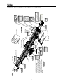
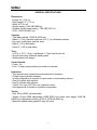
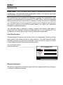
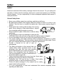
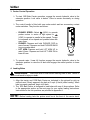
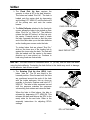
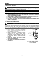
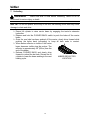
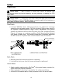
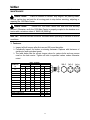
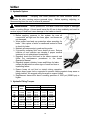
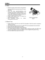
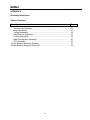
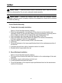
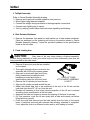
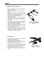
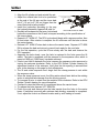
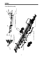
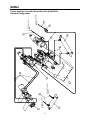
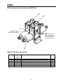
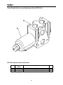
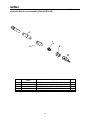
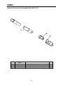
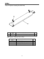
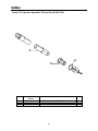
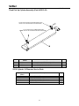
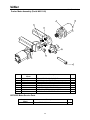
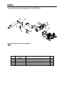
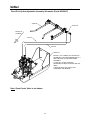
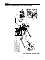
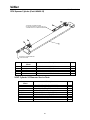
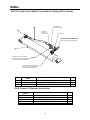
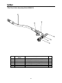
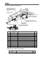
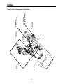
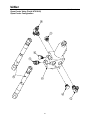
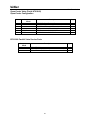
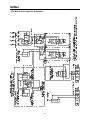
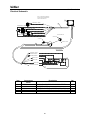
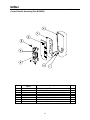
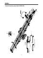
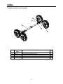
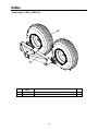
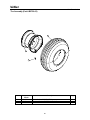
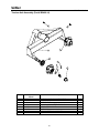
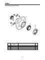
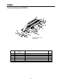
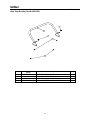
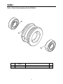
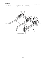
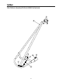
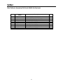
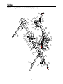
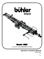
inland
Model 1500
For serial number 08BM1500001 and later
Operator’s and Parts Manual
Bale Carrier
46912
04/08
INLAND WARRANTY POLICY
Buhler Manufacturing products are warranted for a period of twelve (12) months (90 days for commercial
application) from original date of purchase, by original purchaser, to be free from defects in material and
workmanship under correct, normal agricultural use and proper applications.
Buhler Manufacturing’s obligations under this warranty shall be limited to the repair or exchange, at Buhler
Manufacturing’s option, of any Buhler Manufacturing product or part which proves to be defective as provided.
Buhler Manufacturing reserves the right to either inspect the product at the buyer’s location or have it returned to the
factory for inspection.
The above warranty does not extend to goods damaged or subject to accident, abuse or misuse after shipment from
Buhler Manufacturing’s factory, nor to goods altered or repaired by anyone other than an authorized Buhler
Manufacturing representative.
Buhler Manufacturing makes no Express Warranties other than those, which are specifically described. Any
description of goods, including any references and specifications in catalogues, circulars and other written material
published, is for the sole purpose of identifying goods and shall conform to such descriptions. Any sample or model
is for illustrative purposes only and does not create an Express Warranty that the goods conform to sample or model
shown.
The purchaser is solely responsible for determining suitability of goods sold. This warranty is expressly in lieu of
all other warranties expressed or implied. Buhler Manufacturing will in no event be liable for any incidental or
consequential damages whatsoever. Nor for any sum in excess of the price received for the goods for which liability
is claimed.
WARRANTY CLAIMS:
Warranty requests must be prepared on Buhler Manufacturing Warranty Claim Forms with all requested information
properly completed. Warranty Claims must be submitted within a thirty (30) day period from date of failure repair.
WARRANTY LABOR:
Any labor subject to warranty must be authorized by Buhler Manufacturing. The labor rate for replacing defective
parts, where applicable, will be credited at 100% of the dealers posted shop rate. Defective parts will receive an
extra 10% discount to assist with freight or other incidental costs.
GOVERNMENT LEGISLATION:
Warranty terms and conditions are subject to Provincial or State legislation.
IMPORTANT FACTS:
Buckets and Bucket Tines Carry No Warranty
Bent Spears Carry No Warranty
Snowblower Fan Shafts Carry No Warranty
Mower Blades Carry No Warranty
Portable Auger Parts Have Two (2) Year Warranty
Printed in U.S.A.
bühler
1500 Bale Carrier
OPERATORS AND PARTS MANUAL
Table of Contents
Description
TERMINOLOGY AND DECAL LOCATIONS ILLUSTRATIONS……..………...
GENERAL SPECIFICATIONS…..…………………………………………………
INTRODUCTION…………………………………………………………………….
Serial Decal Location…………………………………………………………….
Warranty Registration…………………………………………………………….
SAFETY………………………………………………………………………………
General Safety Notes…………………………………………………………….
Safety Decals……………………………………………………………………..
Important Precautions……………………………………………………………
PRE OPERATION CHECKLIST...…………………………………………………
OPERATION.………………………………………………………………………..
Attaching Bale Carrier to Tractor………………………………………………..
Attaching Bale Carrier Controls to Tractor……………………………………..
Carrier Controls Operation………………………………………………………
Loading Bales……………………………………………………………………..
Bale Pusher Operation…………………………………………………………...
Transporting 1500 Bale Carrier…………………………………………………
Unloading……..…………………………………………………………………..
LUBRICATION.………………………………………………………………………
Pivot Points………………………………………………………………………..
Roller Chain……………………………………………………………………….
Carrier Beams…………………………………………………………………….
MAINTENANCE…………………………………………………………………….
Fasteners………………………………………………………………………….
Hydraulic System…………………………………………………………………
Hydraulic Fitting Torques………………………………………………………..
Chain……………………………………………………………………………….
Wheels/Tires………………………………………………………………………
Storage…………………………………………………………………………….
APPENDIX LIST……………………………………………………………………..
APPENDIX A ASSEMBLY INSTRUCTIONS…………………………………….
APPENDIX B HYDRAULIC ASSEMBLY………………………………………...
APPENDIX C ELECTRICAL ASSEMBLY………………………………………...
APPENDIX D GENERAL ASSEMBLY…………………………………………...
CHECKLIST………………………………………………….………………………
Predelivery………………………………………………………………………...
Customer Delivery………………………………………………………………..
1
Page
2
3
4
4
4
5
5
7
8
9
10
10
10
12
12
14
14
15
16
16
16
16
17
17
18
18
19
19
20
21
22
30
55
59
78
78
78
16
YELLOW
RED
RED
15
15
16
YELLOW
18
1500
2
16
15
10
12. Part # 814490
12
Slow Moving
Vehicle
RED
7
YELLOW
13. Part # 814457
13
AMBER
REFLECTOR
Carrier Beam
Note: 1) Refer to page 7 for detailed
information on safety decals.
2) Awarness signs are shown on one
side only for clarification. Signs are
provided on both left and right sides
except for numbers 1, 2, 5, 6, 8, 9
and14 which are only on the position
indicated.
RIGHT SIDE
BACK
4
11
YELLOW
16
Second Crossmember
Front Crossmember
Side
Bale Fork
Bale Lift Arm
Valve Bank
Front Stop
2
Jack
16 YELLOW
Bale Stop
Pusher
LEFT SIDE
End
9
14
8
5
1
6
FRONT
Clevis
9. Part # 813634
bühler
1500 Bale Carrier
TERMINOLOGY AND DECAL LOCATIONS ILLUSTRATION
bühler
1500 Bale Carrier
GENERAL SPECIFICATIONS:
Dimensions:
- Length: 44’ (13.4 m)
- Deck Length: 37’ (11.3 m)
- Width: 8’6” (2.6 m)
- Weight (empty): 5495 LB (2498 kg)
- Drawbar Vertical Load (empty): 1365 LBF (6071 N)
- GVW: 18720 LB (8491 kg)
Capacity:
- Total bale payload: 13225 LB (6000 kg)
- Bales 6’ (1.8 m) diameter maximum to 4’ (1.2 m) diameter minimum
- Hay crop, small grains, and flax straw
- Eight 4’ (1.2 m) wide bales
- Seven 5’ (1.52 m) wide bales
Tires:
- 4-12.5L x 15 FI - 12 ply, Load Range F, Farm Hwy Service tire
- Six bolt heavy-duty hubs with twine guards
- Walking beam axle design
Control Handle:
- Power: 12v
- Fuse: 15 amp (surge protection provided on machine)
Hydraulics:
- Two remote tractor hydraulics circuits required for operation
- Closed-center hydraulic standard.
- In-field configuration is required for open-center or load-sensing tractors
- One Lift cylinder with restrictor
- One Tilt cylinder with restrictor
- Two 22.2 cu. inch (363.79 cu cm) hydraulic motors
- See Appendix B for details on hydraulic components
Tractor:
- Size: 60 hp (45kW) recommended
- Weight: As per ASAE specification ASAE S365.4 the tractor must weight 12480 LB
(5660 kg) to adequately handle a GVW of 18720 LB (8491 kg)
- Maximum loaded towing speed 20 mph (32 km/h)
3
bühler
1500 Bale Carrier
INTRODUCTION
CAUTION:
Your 1500 Bale Carrier requires a recommended minimum 60 hp
(75kw) tractor. The maximum loaded transportation speed of 20 mph (32 km/h) and
18720 LB (8491 kg) must not be exceeded.
This manual has been provided as information regarding the specifications, safe
operation and maintenance of your agricultural 1500 Bale Carrier. Read and understand
this manual and the tractor manual prior to operating to obtain the best use of operating
your 1500 Bale Carrier. Keep this manual for reference and to forward to new operators
and owners. Contact your local Buhler Inland dealer if you require any assistance,
information or additional manuals.
Your new bale carrier is designed to retrieve, transport, and unload a wide range of
round bales. Sizes that can be accommodated range from 4’ (1.2 m) diameter to 6’ (1.8
m) diameter in a variety of hay crops as well as small grain and flax straw.
Serial Decal Location
The serial decal is located on the left side of the front crossmember. Please record the
serial number in the space provided for future reference. The serial decal will provide
the model and date of manufacture of the Bale Carrier and will be required to obtain
correct replacement parts and complete warranty claims.
For your records, record
Serial Number here: ________________________
B.I.I. FARGO INC.
FARGO NORTH DAKOTA
versatile
farm king
allied
inland
Warranty Registration
The warranty registration and delivery report MUST be completed within thirty (30) days
of delivery to validate the warranty.
4
bühler
1500 Bale Carrier
SAFETY
Read and understand all the safety messages listed in this manual. For your safety and
the safety of others near the machine, learn how to control and operate your 1500 Bale
Carrier properly. It is your responsibility to inform subsequent operators and owners of
these precautions.
General Safety Notes
Keep young children away from machinery and bales at all times.
Be aware that accidents often happen when the operator is tired or in a hurry to get
finished. Take the time to consider the safest way. Never ignore warning signs of
fatigue.
Keep hands, feet, clothing and hair away from moving
parts. Never attempt to clear obstructions or objects
from a machine while the engine is running.
Keep all shields in place. Never alter or remove safety
equipment.
Do not attempt to clear any blockage or reach into the
1500 Bale Carrier with your arm or leg unless the tractor engine is stopped.
Do not load bales of sizes not out lined in the specifications section.
Use proper lighting and safety warnings when transporting equipment on public
roads and during darkness. The slow moving vehicle emblem must be visible. Check
with your local law enforcement agency for specific requirements.
Provide a first-aid kit for use in case of
emergencies.
The safety information in this manual does not
replace safety codes, insurance needs, or laws
governing your area. Be sure your machine
meets the standards set by these regulations.
Keep a fire extinguisher with the machine. Be
sure the extinguisher is properly maintained and
be familiar with its proper use.
Wear close-fitting clothing and cover long hair. Never wear
dangling items such as scarves or bracelets.
Remember that YOU are the key to safety. Good safety
practices protect you and the people around you.
Follow all safety messages in the manual and on safety
signs located on the machine.
It is your responsibility to read and understand this manual completely before
operating the bale carrier.
5
bühler
1500 Bale Carrier
Never leave the tractor unattended while the 1500 Bale Carrier is hooked up, always
shut tractor off and remove key before leaving the tractor seat. A child or even a pet
could engage an idling machine.
Keep the 1500 Bale Carrier on solid ground; rocks and holes can be dangerous for
operation and movement.
Prior to use, check to ensure the attachment is properly hitched.
Improper use of the 1500 Bale Carrier and tractor can cause serious injury or death.
Never operate 1500 Bale Carrier with frayed or damaged hoses or leaking fittings. A
burst could cause one or more hydraulic components to behave erratically causing
serious injury or loss of life.
Operate 1500 Bale Carrier only while seated in the tractor seat.
Do not load bales improperly; always load according to the manual’s operation
procedures.
If for some reason you feel the tractor tipping immediately lower lift arms.
Do not raise lift arms to extreme heights while tractor is on an incline. Be alert for
terrain changes and adjust accordingly.
Allow for 1500 Bale Carrier and tractor length when turning.
Do not overload the GVW of 18720 LB (8491 kg) and when loaded keep the speed
below 20 mph (32 km/h).
Before allowing anyone to operate the machine, for however a short time or
distance, make sure they have been instructed in its safe and proper use.
Review the manual and all safety related items with all operators annually.
Correct other operators not using recommended procedures before an accident
occurs.
When assembling, operating and servicing machinery, wear all the protective
clothing and personal safety devices that could be necessary for the job at hand.
Never work beneath a raised lift arm unless it is securely supported. The control
handle can be moved or a hydraulic leak could cause the arm to drop resulting in
serious injury or death.
Use only service and repair parts made or approved by the equipment manufacturer.
Substituted parts may not meet strength, design, or safety requirements.
Do not modify the machine. Unauthorized modifications may impair the function
and/or safety and affect machine life.
Keep the area used for servicing machinery clean and dry. Wet
or oily floors are slippery. Wet spots can be dangerous when
working with electrical equipment. Be sure all electrical outlets
and tools are properly grounded.
Keep machinery clean. Straw and chaff on hot surfaces are a fire hazard. Do not
allow oil or grease to accumulate on service platforms, ladders or controls. Clean
machines before storage.
Never use gasoline, naphtha or any volatile material for cleaning purposes. These
materials may be toxic and/or flammable.
When storing machinery, cover sharp or extending components to prevent injury
from accidental contact.
6
bühler
1500 Bale Carrier
Safety Decals
The terminology and decal location illustration shows the approximate location and
detail of safety decals. To install safety decals ensure the installation area is clean and
dry. Decide on the exact position before you remove the backing paper. Remove the
smallest portion of the split backing paper and align over the specified area. Carefully
press in place. Slowly peel back the remaining paper and smooth the remaining portion
in place. Small air pockets can be pierced with a pin and smoothed out. Keep all decals
clean and replace any that are damaged or missing. Replacement decals are available
from you local dealer. The following pictorials indicate important precautions to be used
during the operation of the 1500 Bale Carrier.
1. Part # 813624
5. Part # 813627
2. Part # 813625
3. Part # 21867 4. Part # 813626
6. Part # 813632
7. Part # 813633
8. Part # 813635
WARNING
HIGH-PRESSURE FLUID HAZARD
To prevent serious injury or death:
Relieve pressure on system
before repairing or adjusting or disconnecting.
Wear proper hand and eye protection
when searching for leaks. Use wood or
cardboard instead of hands.
Keep all components in good repair.
10. Part # 813637
SW700
11. Part # 813636
12. Part # 814490
13. Part # 814457
19. Part # A7017-00
1500
14. Part # 813952
15. Part # 967053
RED RELFECTIVE
BUHLER BALE CARRIER 1500/2500 SNUBBER UNIT
P/N: 813949
(NO SERVICEABLE PARTS INSIDE)
CONTINUITY LIGHT
DECAL PN: 813952
16. Part # 967055
YELLOW REFLECTIVE
7
17. Part # 813631
ORANGE FLOURESCENT
18. Part # 813628
AMBER REFLECTIVE
bühler
1500 Bale Carrier
Important Precautions
The alert symbol is used throughout this manual. It indicates attention is required and
identifies hazards and alerts you that your safety is involved. Follow the recommended
precautions.
CAUTION
Indicates a potentially hazardous situation, which may result in
injury. It may also be used to alert against unsafe practices.
WARNING
The warning symbol indicates a potentially hazardous
situation, which could result in death or serious injury and includes hazards that are
exposed when guards are removed. It may also be used to alert against unsafe
practices.
DANGER
The danger symbol indicates an imminently hazardous
situation, which will result in death or serious injury. This signal word is limited to the
most extreme situations, typically for machine components, which for functional
purposes, cannot be guarded
8
bühler
1500 Bale Carrier
PRE-OPERATION CHECKLIST
CAUTION
Make sure the tractor has a 60 hp (45 kw) or greater rating
and a mass of 12480 LB (5660 kg). Make sure the drawbar is capable of supporting the
1500 Bale Carrier empty or loaded.
WARNING
The tractor must be equipped with an approved Roll over
Protection Structure (ROPS) and safety belts to help prevent personal injury or death
caused by tractor roll over.
To ensure safe and proper operation of the 1500 Bale Carrier, inspect the following
items prior to operation and daily thereafter. Refer to operation, lubrication and
maintenance sections for detailed instructions.
Prior to first use verify that the 1500 Bale Carrier has been properly assembled and
that the operator understands the safety, operating, and maintenance requirements.
Check for missing fasteners and replace if necessary. Refer to maintenance section
for details.
Check and maintain proper tire pressure of 90 psi (620 kpa).
Check for loose wheel bolts. Bolts must be torqued to 125 ft LB (170 Nm).
Clean 1500 Bale Carrier of any foreign material that may have accumulated from
previous run.
Lubricate all points requiring daily lubrication.
Check chain tension and adjust if necessary with front sprocket adjusting bolt
(approximately 6” (15 cm) of upward slack). This is verified by raising the chain by
hand.
Ensure top surface of bale carrier beams are properly coated with a graphite coating
to reduce bale friction while pushing bales back.
Ensure that the tractor used to pull the 1500 Bale Carrier is in working order
according to the tractor manual.
Verify the 1500 Bale Carrier is properly coupled to the tractor with the safety chain.
Inspect all safety reflective decals, slow moving vehicle decals and lights where
applicable.
Inspect the hydraulic system on the 1500 Bale Carrier and your tractor for leaks or
any other damage.
Ensure the control handle actions reflect the movements of the 1500 Bale Carrier.
Inspect all electrical connections to ensure proper function of the machine
Ensure transport safety chain is disengaged from bale lift arm and stored on chain
lug located on second cross member. Failure to do so may cause damage to lift arm.
.
9
bühler
1500 Bale Carrier
OPERATION
CAUTION
Prior to operation ensure the operator has read and
understands the safety requirements of the 1500 Bale Carrier. Ensure the pre-operation
checks have been completed prior to operation.
1. Attaching Bale Carrier To Tractor
CAUTION
Shut off tractor, engage parking brake and remove key before
working around 1500 Bale Carrier. Refer to tractor manual for tractor parking
procedures.
CAUTION
Use only the drawbar to couple the 1500 Bale Carrier to the
tractor. Ensure drawbar is capable of handling the 1500 Bale Carrier load. The tractor
must have a minimum mass of 12480 LB (5660 kg) and recommended 60 hp (45 kw).
Using the tongue jack, raise tongue to align with hitch pin, adjust clevis position
as necessary to level the carrier beams.
Position tractor and secure with locking type drawbar pin (not supplied). Use an
approved hitch pin with a mechanical retainer.
Route safety chain around the hitch clevis, around drawbar support and back
hook. Refer to tractor manual for further drawbar instructions.
Do not use intermediate support on drawbar as attaching point.
Store safety chain off the ground when not in use. If safety chain is damaged in
any way, contact your dealer for a replacement.
For serial number 08BM1500001 and later, open-center valve is a factoryinstalled feature
Note: The bale carrier is factory-configured to operate with tractors
having CLOSED-CENTER hydraulic systems (page 31).
For tractors with OPEN-CENTER or LOAD-SENSING hydraulic systems,
refer to the configuration on pages 33, 50 and 51.
2. Attaching Bale Carrier Controls To Tractor
Bale lift and push functions are controlled by the 1500 Bale Carrier valve. Two
hoses complete with black hydraulic tip covers supply pressure and tank. The
retraction hose is designated with a check valve and ensures proper flow through
the valve. Connect the return hose to the retract circuit and the extend hose to
opposite extend port.
The tilt function is controlled by the tractor’s remote valve. Two hoses complete
with red hydraulic tip covers supply extension and retraction.
Connect control handle harness to the machine harness. Connection is made at
the snubber unit by matching the appropriate socket and plug.
10
bühler
1500 Bale Carrier
The power required to operate the 1500 Bale Carrier is supplied by the tractors
12-volt electrical system. Connect the red wire to the tractor positive and green to
tractor ground. Connection may be made via tractor accessory plug or alternate
method. The 15-amp fuse must be used on the positive wire as supplied.
Verify 1500 Bale Carrier operation matches 1500 Bale Carrier control handle
decal.
11
bühler
1500 Bale Carrier
3. Carrier Control Operation
To start 1500 Bale Carrier operation, engage the remote hydraulic valve in the
extension position. Lock valve in detent. Valve to remain constantly on during
operation.
The control handle is fitted with one rocker switch and two momentary contact
rocker switches. They function as follows:
o PUSHER SPEED: Select
(HIGH) to operate
pusher motors in series at high speed or
(LOW) to operate in parallel at low speed. Torque
is increased at low speed and pushes bales with
more force.
o PUSHER: Depress and hold PUSHER FWD to
move forward. Depress and hold PUSHER BACK
to move pusher back.
o LIFT ARM: Depress and hold LIFT ARM UP to
raise lift-arm. Depress and hold LIFT ARM DN to
lower lift-arm.
CONTROL
HANDLE
To operate raise / lower tilt function engage the remote hydraulic valve in the
extension position to raise the tilt deck and engage the retract position to lower
the deck.
4. Loading Bales
WARNING Make sure area is clear before lowering bale lift-arm. Failure to
do so could result in injury or death.
Align the tractor and 1500 Bale Carrier as indicated in the pictoral for pick up
method used. Slowly approach the bale at 5 mph (8 km/h) while loading. When
bale is properly captured, begin to lift bale.
The 1500 Bale Carrier is designed to load bales with one of three options. Refer
to the appropriate section on the next page for your option loading instructions.
Instructions for the fork positions are provided in appendix A.
NOTE:
Before loading bale the pusher must be at the front of the carrier deck.
12
bühler
1500 Bale Carrier
The Fixed Pick Up Arm requires the
operator to drive at 90° to the bale direction.
The bales are loaded “End On”. The bale is
loaded onto the carrier deck by depressing
and holding LIFT ARM UP until the bale rolls
off the pickup arm and onto the carrier
beams.
The Bale Deflector attached to the fixed pick
up arm allows the bales to be picked up from
either “End On” or “Side On.” The deflector
rotates the bale 90° before it is lifted up onto
the carrier. Forward travel is used to rotate
the bale. Approach the bale so that the outer
end of the bale rides up on the bale deflector
as the loading arm moves under the bale.
To pickup bales that are placed “End On,”
drive so the inner arm of the loading fork is
against the inner edge the bale. The bale will
then be loaded onto the carrier in the same
direction as it was picked up. Continue to
load using fixed arm instrucitons.
FIXED PICK UP ARM
BALE DEFLECTOR
NOTE:
The bale should be contacted about 12” (30 cm) from its outer end when
using the bale deflector. Contacting the bale further to the inside may result in damage
to the deflector, bale lift arm or bale.
The Rotating Pick Up Arm (RPU) loads
bales “side on”. The lift arm starts in the
lowered position. Drive forward until the forks
are positioned around the ends of the bale
with the inside stationary fork as close as
possible to the bale. Depress and hold LIFT
ARM UP. The bale is then squeezed on end
until the pressure matches the sequence
valve setting that rotates and raises the bale.
RPU LOADING BALE
When the bale is lifted above, the bale is
released by depressing LIFT ARM DN. This
releases the bale and returns the RPU to the
ready state for the next bale. Refer to the
assembly instructions for adjusting RPU’s
settings.
RPU LIFTING BALE
13
bühler
1500 Bale Carrier
5. Bale Pusher Operation
CAUTION
To avoid misbalanced loads the operator is only required to
push back one bale length to prepare for the next bale.
NOTE: Lower loading arm before operating the pusher.
Depress and hold PUSHER BACK and move bales far enough to the rear to
provide room to load the next bale.
Return pusher all the way to the front by depressing and holding PUSHER FWD.
Hi speed / Low torque mode is recommended for normal use.
Low speed / High torque mode is for heavier payloads or situations where bales
are wet or resist sliding.
6. Transporting 1500 Bale Carrier
WARNING
Do not tow over 20 mph (32 km/h) when loaded. Turn on
flashing lights when transporting on public roadways. Obey local regulations regarding
road transport. Raise bale lift arm and use the safety chain when transporting. Ensure
the lift arm chain latch is used to prevent the safety chain from dislodging or loosening.
Do not transport if end bale is overhanging
beams. Beam should extend beyond last bale
for a minimum of 2’ (61 cm).
Raise lift arm prior to transport. Always
engage lift arm safety chains when
transporting on public roadways or when not
in field. Lock chain in position with latch
provided.
Monitor the condition and position of bales
that are being transported.
Slow speed when transporting over bumps or
rough terrain.
14
LATCH
SAFETY CHAIN
LIFT ARM
LIFT ARM SAFETY CHAIN
ILLUSTRATION
bühler
1500 Bale Carrier
7. Unloading
DANGER
Make sure area is clear before unloading. Failure to do so
could result in serious injury or death.
NOTE: Do not run pusher all the way to the end, the resulting shock load may cause
damage to chain and drive.
Extend tilt cylinder to raise carrier beam by engaging the tractor’s extension
hydraulics.
Depress and hold the PUSHER BACK switch to push the bales off the carrier
beam.
Once the rear bale has been pushed off the carrier, slowly drive forward while
pushing the bales back (unloading) to keep all bale ends in contact.
When amber reflector on inside of the carrier
beam becomes visible stop the pusher. The
reflector is approximately 26” (66cm) from the
end of the beam.
Release PUSHER BACK and slowly drive
forward to unload the last bale. Retract the tilt
cylinder to lower the beam and begin the next
AMBER REFLECTOR
loading cycle.
LOCATION
15
bühler
1500 Bale Carrier
LUBRICATION
CAUTION
Place all controls in neutral, stop engine, set parking brake
and remove ignition key before inspecting, servicing, adjusting or repairing the 1500
Bale Carrier.
CAUTION
Ensure the 1500 Bale Carrier tires and hitch are securely
blocked. Otherwise, verify the 1500 Bale Carrier is properly coupled to the drawbar on a
tractor with a minimum mass of 12480 LB (5660 kg).
Pivot Points
Lubricate 1500 Bale Carrier bushings and pivots every eight hours of average
operation with high-grade grease at all fitting locations. Select grease based on
the expected outside temperature range. Lithium, Molybdenum and synthetic
greases are preferred. Use the tractor hour meter as a guide. Increase lubrication
intervals for extreme use or adverse conditions. Each pivot should be lubricated
until grease is visible at pin. The fixed arm carrier has 12 lubrication points and
the RPU carrier has 13 points. Refer to the illustrations below for locations.
HYDRAULIC CYLINDER ENDS
HITCH BEAM
AXLE BEARING
RPU PIVOT LEFT
AND RIGHT SIDES
HYDRAULIC CYLINDER
ENDS
AXLE BEARING
RPU LUBRICATION
ILLUSTRATION
BUSHINGS
LUBRICATION ILLUSTRATION
Roller Chain
Manually brush SAE lubricant while chain is stationary.
Lubricate the chain every time bolt torque maintenance is performed.
Carrier Beams
Apply a graphite coating such as Slip PlateTM to the carrier beams as required to
ensure a smooth push back operation.
Follow application instructions as provided by the coating manufacturer.
At the end of the season apply a coating to prevent rust on the carrier beams.
16
bühler
1500 Bale Carrier
MAINTENANCE
CAUTION
Place all controls in neutral, stop engine, set parking brake,
remove ignition key and wait for all moving parts to stop before servicing, adjusting or
repairing the 1500 Bale Carrier.
CAUTION
Ensure the 1500 Bale Carrier tires and hitch are securely
blocked. Otherwise, verify the 1500 Bale Carrier is properly coupled to the drawbar on a
tractor with a minimum mass of 12480 LB (5660 kg).
NOTE:
Service intervals should be increased when operating in extreme or difficult
conditions.
1. Fasteners
Inspect all bolt torques after first use and 50 hours thereafter.
Periodically inspect for broken or missing fasteners. Replace with fasteners of
similar size and equivalent grade.
The table below lists the correct torque values for various bolts and cap screws
used on the bale carrier. Tighten all bolts to specified values unless otherwise
noted.
BOLT TORQUE
SAE 5
BOLT
DIAMETER
"A"
lb-ft
N.m
lb-ft
N.m
lb-ft
N.m
1/4"
6
8
9
12
12
17
5/16"
10
13
19
25
27
36
3/8"
20
27
33
45
45
63
7/16"
30
41
53
72
75
100
SAE 2
SAE 8
1/2"
45
61
80
110
115
155
9/16"
70
95
115
155
165
220
5/8"
95
123
160
215
220
298
3/4"
155
225
290
390
400
540
7/8"
170
230
420
570
650
880
1"
225
305
630
850
970
lb-ft
125
33
1320
LOCATION
WHEEL HUB BOLTS
ALL CARRIAGE BOLTS
N.m
170
45
17
bühler
1500 Bale Carrier
2. Hydraulic System
WARNING
Escaping fluid under pressure can have sufficient force to
penetrate the skin, causing serious personal injury. Before repairing, adjusting, or
disconnecting lines, be sure to relieve all pressure.
WARNING
Never operate the 1500 Bale Carrier with frayed or damaged
hoses or leaking fittings. A burst would cause the lift arm to drop suddenly and result in
serious injury or death and cause damage to the loader or tractor.
Before applying pressure to the system, be sure all
connections are tight and the lines, pipes, and hoses are
not damaged.
Wear proper hand and eye protection when searching for
leaks. Use a piece of wood or cardboard instead of hand
to check for leaks.
Maintain all components in good working order.
If injured by escaping fluid, see a doctor at once. Serious
infection or toxic reaction can develop if proper medical
treatment is not administered immediately.
Regularly check the fluid level in the tractor reservoir and
follow the maintenance procedures in the tractor
Operator’s Manual.
Regularly inspect cylinders, hoses and fittings for leaks,
crimps and abrasions or other signs of wear and tear or
impending failure.
Ensure hoses do not bind or stretch during operation.
Always keep hoses tied or supported to prevent rubbing against sharp areas or
being pinched. We suggest using tie wraps to support hoses.
Replacement hoses must have a working pressure of 3000 psi (20685 kpa) or
higher.
3. Hydraulic Fitting Torques
Dash Size
Thread
Size
-04
-05
-06
-08
-10
-12
-14
-16
-20
-24
7/16-20
1/2-20
9/16-18
3/4-16
7/8-14
1-1/16-12
1-3/16-12
1-5/16-12
1-5/8-12
1-7/8-12
Jam Nut or Straight
ORB Fitting Torque
(ft-lbs)
(NM)
14-16
20-22
18-20
24-27
24-26
33-35
50-60
68-78
72-80
98-110
125-135
170-183
160-180
215-245
200-220
270-300
210-280
285-380
270-360
370-490
SAE 37° (JIC)
Swivel Nut Torque
(ft-lbs)
(NM)
10-11
13-15
13-15
18-20
17-19
23-26
34-38
47-52
50-56
69-76
70-78
96-106
80-90
110-122
94-104
127-141
124-138
169-188
156-173
212-235
18
bühler
1500 Bale Carrier
4. Chain
Check for proper chain tension and sprocket
alignment after first use and every 50 hours
thereafter.
Turn the front sprocket-adjusting bolt
clockwise until there is approximately 6” (15
cm) of upward slack in the chain at the center
of the track. Clockwise increases tension and
counter clockwise reduces tension.
Proper chain tension may be verified by
raising the chain by hand.
See
lubrication
section
for
further
maintenance instructions.
FRONT ADJUSTING
BOLT
5. Wheels / Tires
Inspect hub bolts after first use and 50 hrs thereafter. Hub bolts must be torqued to
125 ft-lb (170 Nm).
Thread-locking compound such as Locktite 242 is recommended for the hub bolts.
Ensure that dust caps are firmly in place.
Check tires pressure regularly: 90 psi (620 kpa).
The wheel bearings should be inspected and re-packed annually with SAE multi
purpose type grease. Grease every 500hrs if hub is supplied with grease fitting.
Air valve should face away from the hub.
19
bühler
1500 Bale Carrier
6. Storage
CAUTION
Place all controls in neutral, stop engine, set parking brake and
remove ignition key before inspecting, servicing, adjusting or repairing the 1500 Bale
Carrier.
CAUTION
Ensure the 1500 Bale Carrier tires and hitch are securely blocked.
Otherwise, verify the 1500 Bale Carrier is properly coupled to the drawbar on a tractor with
a minimum of 12480 LB (5660 kg).
Start of Season
Clean and inspect the bale carrier when taking it out of storage. Ensuring that the
bale carrier is in optimum condition at the start of the season reduces the chances of
a costly breakdown during the season.
Clean and inspect chains and chain rollers for excessive wear or stiffness. Check for
proper adjustment and alignment.
Lubricate entire bale carrier. Ensure that all grease fittings are in place and taking
grease properly.
Operate the bale carrier for a short time. Check that all moving parts are operating
freely. Check for hydraulic leaks.
Inspect and repack wheel bearings with SAE multi purpose type grease.
Replace and secure safety shields. Review safety regulations.
Check all bolts for tightness. Replace lost or worn bolts.
Check that tires are properly inflated.
Review the Operator’s Manual.
During The Season
At the end of each day of operation park the bale carrier in a clean, dry, sheltered
area.
Lubricate areas requiring daily lubrication.
Remove any build up of hay or straw.
End Of Season
Replace worn or damaged parts and replace if necessary. To avoid costly delays
contact your dealer for replacement parts before the start of the next season.
Store the bale carrier in a clean, dry, sheltered area.
Replace all missing or broken bolts with bolts of similar size and grade.
Clean the baler carrier thoroughly. Dirt draws moisture that rusts metal.
Repaint chipped or worn areas. Paint is available from your dealer.
Clean chains and brush with SAE light machine oil (or equivalent) to prevent rust.
Repaint the top of the carrier beams with graphite paint such as Slip PlateTM to
prevent rust.
20
bühler
1500 Bale Carrier
APPENDIX LIST
Description
Appendix
Assembly Instructions…..…………………………………………………….
A
Hydraulic Assembly……………………………………………………………
B
Electrical Assembly………..…………………………………………………..
C
General Assembly….…………………………………….…………………...
D
21
bühler
1500 Bale Carrier
APPENDIX A
Assembly Instructions
Table of Contents
Description
Carrier Bundled Assembly……………………………………………………….
Tandem Axle Assembly………………………………………………………
Brace Weldment……………………………………………………………...
Taillight Assembly…………………………………………………………….
Bale Retainer Weldment……………………………………………………..
Fixed Loading Arm…………………………………………………………..
Bale Deflector Arm Assembly……………………………………………...
RPU Assembly………………………………………………………………...
Carrier Bundled Assembly Drawing…………………………………………….
Carrier Bundled Assembly Parts List…………………………………………...
22
Page
23
23
23
24
24
24
25
25
27
28
bühler
1500 Bale Carrier
CAUTION
Make sure area is clear of obstructions, well lit, and has sufficient
room for safe assembly. Do not work underneath raised assembly.
CAUTION
Ensure the carrier’s tires and hitch are securely blocked.
Otherwise, verify the carrier is properly coupled to the drawbar on a tractor with a minimum
of 12480 LB (5660 kg).
Carrier Bundled Assembly
1. Tandem Axle Assembly Installation
Refer to Carrier Bundled Assembly drawing:
Raise the main assembly to a maximum of three feet to insert the tandem axle
assembly (A2400-14) on both sides. Make sure that the assembly is securely held in
place. Support assembly with the appropriate rated stands for the load.
Insert the tandem axle assembly on to the axle Beam (C2407-00).
Insert the tandem axle locator (C8005-00) between the tandem axle assembly
bushings, continue to insert the axle assembly.
Insert nut (984077) and set screw (813547) into the locator.
Install tires
Torque all fasteners to the torque specifications listed in the maintenance section of
this manual.
Lubricate axle and hubs; refer to lubrication section for details.
Recheck all bolt torques after first use.
2. Brace Weldment Installation
Refer to Carrier Bundled Assembly drawing:
The carrier has six braces that need to be installed on the undercarriage of the main
assembly.
All fasteners require a flat washer and a lock nut.
Loosely assemble and fasten all braces.
Torque all hardware to the required torque specifications listed on the maintenance
section of this manual.
23
bühler
1500 Bale Carrier
3. Taillight Assembly
Refer to Carrier Bundled Assembly drawing:
Remove and inspect all required hardware from parts box.
Mount lights using fasteners supplied
Connect the taillight wiring harnesses to their appropriate connections.
Connect main lighting plug to tractor.
Test by verifying correct lamps illuminate when signalling and braking.
.
4. Bale Retainer Weldment
Remove the hardware from parts box and transfer on to bale retainer weldment.
Place the weldment on the matching bolt holes in the position shown in Carrier
Bundled Assembly drawing. Torque the provided hardware to the specifications
listed on the bolt chart.
5. Fixed Loading Arm
CAUTION
Stay clear of the arm when testing a finished assembly.
Ensure during assembly to keep your entire body out from underneath parts that are
being attached to the main frame.
Remove lift arm pivot pins that are installed
on the carrier.
Thoroughly lubricate all pins involved in the
assembly with SAE multi purpose grease.
36.0"
Align arm to pivots with open end of arm
facing forward and reinstall pins with
hardware provided and torque to
FIXED LIFT ARM
specifications called for in the bolt chart.
ATTACHMENT ASSEMBLY
Remove the lift cylinder pin from the arm.
LAYOUT
Align the lift cylinder rod and reinstall the pin.
Adjust the outside bale fork to be positioned at the end of the lift arm and the
inner bale fork about 36” (91 cm) from the end.
Recheck all hardware so that every bolted connection on the lift arm is torqued
according to the specifications of the bolt chart.
Approach the bale and inspect to ensure the spacing of the forks is accurate.
For first operation, cycle the lift arm slowly with a bale and inspect just before
lifting bale from ground.
Finish the cycle and observe how the bale transits from the forks to the carrier
beam. If transition is smooth with minimum bale binding, assembly is completed.
If not, adjust the forks to a different location and try until loading is smooth.
24
bühler
1500 Bale Carrier
6. Bale Deflector Arm Assembly
Remove all hardware that is included with the
deflector assembly.
Remove the two top bolts from outer fork on
lift arm.
Maintain the spacing of the forks if already
preset. If not, set spacing as described in the
fixed pick up arm assembly section.
Insert the coned end of the deflector onto the
end of the outer fork.
Align the bolt holes from the removed bolts
on the outer fork and the end of the deflector
attachment.
Insert hardware supplied with the deflector
the same way the hardware was installed
before the attachment was added.
Torque all hardware according to the bolt
chart and tighten the set screws on the cone
also according to the chart.
During first bale lift, cycle slowly and watch
for excessive flexing or movement of the
deflector. If movement is detected, stop cycle
and retorque all hardware involved.
BALE DEFLECTOR
ATTACHMENT ASSEMBLY
LAYOUT
7. RPU Assembly
Remove lift cylinder and install Pilot Check
assembly (see Appendix B)
Reinstall cylinder at base end only.
Lubricate all pins involved in RPU attachment
with a SAE multi purpose grease.
Align arm to pivots with open end of arm
facing away from the carrier and reinstall pins
with hardware provided and torque to
specifications called for in the bolt chart.
Remove the lift cylinder pin from the RPU
arm.
25
RPU ATTACHMENT
ASSEMBLY LAYOUT
bühler
1500 Bale Carrier
Align the lift cylinder rod and reinstall the pin.
ADJUSTABLE FORK
Adjust the outside bale fork to be positioned
at the end of the lift arm and the inner bale
fork 6” (15 cm) to 8” (20 cm) bigger than the
BALE WIDTH + 6” TO 8”
size of bale that is being loaded.
Install the hydraulics according to the way
the hydraulic assembly Appendix B calls for.
ROTATING PICK UP ARM
Recheck all hardware so that every bolted and
hydraulic connection on the lift arm is torqued according to the specifications of
the torque charts.
Depress LIFT ARM UP. The RPU cycle should begin with a squeeze action, then
lift and rotate. After rotation is complete the lift continues until the bale is above
the carrier beams.
Release LIFT ARM UP when bale is above the carrier beam. Depress LIFT ARM
DN to release the bale and return to ground level ready for the next bale.
For the first operation, cycle the lift arm slowly with the bale and observe the
RPU operation.
Approach the bale slowly; once the bale is captured in the forks press the lift
switch. The bale is squeezed until the pressure in the sequence valve, which is
preset at 1800 psi (12400 kpa), has been achieved
If bale is not held in between the forks increase the sequence valve pressure by
turning the setscrew clockwise. Refer to the RPU Rotate Cylinder drawing for
adjustment location of the setscrew. Verify that the fork spacing is accurate and
refer to the drawing on this page for fork adjustments.
The lift and rotate sequence won’t begin until the clamp pressure is met within
the sequence valve.
When the clamp pressure is met, the lifting action should start before the rotating
action to minimize bale damage from the moving ground.
To increase lift prior to rotate turn the restrictor knob clockwise. Refer to the RPU
Rotate Cylinder drawing for more information.
Continue to raise the bale until it is positioned above the carrier beam.
To release the bale, depress LIFT ARM DN.
Finish the cycle and observe how the bale transits from the forks to the carrier
beam. If transition is smooth with minimum bale binding, assembly is completed.
If not, adjust the forks to a different location and try until loading is smooth.
26
5
9
B B
14 17 17 20
27
6
3
8
BALE CARRIER ASSEMBLED
7
13 17 20
23 18
REAR VIEW OF BALESTOP PLACEMENT
AS VIEWED FROM A A
13 17 20
12 19
1
6 BOLTS PER
WHEEL
2 11
TO MAIN WIRING HARNESS
4
A
BRACES USE SAME HARDWARE AS AXLE
A
UNDERSIDE VIEW OF TAILLIGHTS / WIRING HARNESS
AS VIEWED FROM B B
10
YELLOW LENSE
21
12 19
24
15 16 19
25
bühler
1500 Bale Carrier
Carrier Bundled Assembly
bühler
1500 Bale Carrier
Carrier Bundled Assembly
ITEM
COMPONENT
DESCRIPTION
QTY
PART NUMBER
1
B2400-14
AXLE ASSEMBLY
2
2
B2700-03
TIRE ASSEMBLY
4
3
C2407-00
TANDEM AXLE LOCATOR
2
4
C2907-00
SMV BRACKET & TAIL LIGHT MOUNT
1
5
C7035-00
REAR BRACE WELD'T
2
6
C7036-00
CENTER BRACE
2
7
C8005-00
AXLE
1
8
C8006-00
FRONT BRACE WELD'T
2
9
C8009-00
BALE RETAINER WELD'T-YELLOW
1
10
INE7045-00
LIGHT MOUNT BRACKET
1
11
813653
BOLT 0.563 NF X 1.75 (WB12)/HUB
24
12
81527
BOLT HEX 0.25NC X 1.00 GR5 PL
10
13
967274
BOLT HEX 0.500NC X 1.50 GR8 PL
34
14
81629
BOLT HEX 0.500NC x 3.5 GR5 PL
4
15
81525
BOLT HEX 0.250NC X 0.75 UNC GR5 PL
2
16
812624
WASHER 0.250 FLAT BS PL
2
17
84048
WASHER 0.500 FLAT SAE BS PL
18
948077
NUT HEX JAM 0.500NC GR2PL
19
81922
NUT LOCK (NYLON) 0.25NC GR B PL
12
20
813663
NUT LOCK (STEEL) 0.500NC X 1.50 GRC PL
38
21
814196
LAMP-AG/DUAL/LH/4-WAY WP
1
22
814195
LAMP-AG/DUAL/RH/4-WAY WP
1
23
813547
SET SCREW SQHDCUP 0.500 NC
2
24
967075
SMV SPADE MOUNT
1
25
967066
SMV SIGN
1
28
42
2
bühler
1500 Bale Carrier
NOTE PAGE
29
bühler
1500 Bale Carrier
APPENDIX B
Hydraulic Assembly
NOTE:
1) Hydraulic Assembly methods and layouts are common to the right and
left sides. Only one side of each component is shown in this manual.
2) Seal Kits and Service Parts are only listed in the parts lists and are not indicated on
the illustrations.
Table of Contents
Description
Carrier Hydraulic Assembly Schematic (Standard Configuration). ……………
Valve Bank Assembly………….….……………………………………….…....
FPS Directional Valve Bank Assembly……………………………………...
Series Parallel Valve (Low and High Speed)……………………………….
Hydraulic Return Line Assembly………………………………………………..
Hydraulic Pressure Line Assembly…………………………………………...
Carrier Tilt Assembly……………………………………………………………..
Carrier Tilt Cylinders Hydraulic 3/8 line………………………………………...
Fixed Pick Up Cylinder Assembly………………………………………………
Pusher Motor Assembly………………………………………………………….
Carrier Hydraulic Assembly Hardware…………………………………………
Fixed Pick Up Arm Hydraulic Assembly Schematic……………………………..
RPU Hydraulic Assembly…………………………………………………………...
RPU Squeeze Cylinder…………………………………………………………..
RPU Lift Cylinder………………………………………………………………….
Pilot Check Valve Assembly………………………………………………….
RPU Rotate Cylinder……………………………………………………………..
Open-Center Configuration Schematic……………………………………………
Open-Center Valve………………….……………………………………………
1500 Bale Carrier Hydraulic Schematic…………………………………………..
30
Page
31
33
35
36
37
38
39
40
41
42
43
44
45
46
47
48
49
50
51
53
TO TRACTOR COUPLER
(RETRACT)
TO TRACTOR COUPLER
(EXTEND)
TO TRACTOR COUPLER
(RETRACT)
TO TRACTOR COUPLER
(EXTEND)
bühler
1500 Bale Carrier
Carrier Hydraulic Assembly Schematic (Part # A8000-04)
Standard Configuration
31
bühler
1500 Bale Carrier
Carrier Hydraulic Assembly (Part # A8000-04)
Standard Configuration
Item
1
2
3
4
5
6
7
8
9
10
11
Component
Part #
A8002-01
A7010-00
A7011-00
A8012-00
A8013-00
A7013-00
A8011-00
115001
812176
29105
886704
Description
1500 BALE CARRIER VALVE BANK ASSEMBLY
HYD ASSY 1/2 X 130 RETURN LINE
HYD ASSY 1/2 X 130 PRESSURE LINE
TILT CYLINDER ASSY 3 X 10 PIN EYED
TILT CYLI ASSY HYD 3/8 HOSE
TILT ASSY LIFT ARM CYLINDER
MOTOR MT ASSY 1500 BALE CARRIER 22.2 CU
HOSE 1/2 X 24 3/4 SWFJIC X 7/8
HOSE 3/8 X 96 9/16 SWF X JIC
HOSE 1/2 X 28 3/4 SWFJIC
ADAPTOR STR 3/4 MJIC
32
Qty
1
1
1
1
2
1
1
4
2
4
1
bühler
1500 Bale Carrier
**
Valve Bank Assembly (Part # A8002-01)
(**) To be used only with OPEN-CENTER Configuration.
33
bühler
1500 Bale Carrier
Valve Bank Assembly (Part # A8002-01)
Item
1
2
3
4
5
6
7
8
9
10
11
Component
Part #
C8013-00
B7010-00
B8008-00
E2781-00
81549
812362
813667
811916
811414
812080
810582
Description
VALVE BANK MOUNT WELDMENT
SERIES/PARALLEL VALVE (2-SPEED)
VALVE ASSY FPS DIRECTIONAL
FLOW RESTRICTOR
BOLT HEX 0.313NC X 0.75 GR5PL
NUT LOCK (STEEL) 0.313NC GRBPL
TEE RUN 1/2 MJIC X 3/4 MORB
ELBOW 90 3/4 MORB X 9/16 MJIC
ELBOW 90 3/4 MORB X 3/4 MJIC
ADAPTOR STR 3/4 MORB X 3/4 MJIC
BOLT HEX 0.313NC X 3.00 GR5PL
34
Qty
1
2
1
1
4
8
3
2
4
3
4
bühler
1500 Bale Carrier
FPS Directional Valve Assembly (Part # B8008-00)
5
2
1
2450 PSI PLUG
FACING FORWARD
4
NOTE: THE SECOND ITEM
4 IS NOT VISIBLE BUT IS
ON THE OPPOSITE SIDE IN
THE POSITION OF THE
OPEN HOLE IN THIS VIEW
3
B8008-00 FPS Valve Service Parts
Item
1
2
3
4
5
6
Compone
nt
Part #
22208-01
22149
222083-03
812081
22208-02
X2684
Description
MV4-17 SPOOL SECTION
CROSS OVER RELIEF VALVE BALE CARRIER SET 2400
C07-12TD COIL
PLUG 3/4 MORB STL
MV4-A LOCK VALVE
SEAL KIT VALVE BANK (ITEM NOT VISIBLE)
35
Qty
2
1
4
2
1
2
bühler
1500 Bale Carrier
Series/Parallel Valve Low and High Speed (Part # B7010-00)
2
1
B7010-00 Parallel Valve Service Parts
Item
1
2
3
Component
Part #
22083-03
22083-01
X2684
Description
C07-12TD COIL
SERIES/PARALLEL VALVE (LOW &HIGH SPEED)
SEAL KIT VALVE BANK (ITEM NOT VISIBLE)
36
Qty
1
1
1
bühler
1500 Bale Carrier
Hydraulic Return Line Assembly (Part # A7010-00)
1
3
2
5
4
Item
1
2
3
4
5
Component
Part #
29170
812841
813119
813305
813666
Description
HOSE 1/2 X 130 3/4 MORB X 3/4
MALE TIP 0.5 BODY 0.75 ORB
ADAPTOR STR 3/4 MORB X 3/4 MORB
DUST CAP 0.5 BLACK
VALVE CHECK 3/4 ORB LINE
37
Qty
1
1
1
1
1
bühler
1500 Bale Carrier
Hydraulic Pressure Line Assembly (Part # A7011-00)
1
2
3
Item
1
2
3
Component
Part #
29170
812841
813305
Description
HOSE 1/2 X 130 3/4 MORB X 3/4
MALE TIP 0.5 BODY 0.75 ORB
DUST CAP 0.5 BLACK
38
Qty
1
1
1
bühler
1500 Bale Carrier
Carrier Tilt Cylinder Assembly (Part # A8012-00)
1
2
Item
1
2
Component
Part #
813640
24895
Description
Qty
ELBOW 90 9/16 MORB ADJ 9/16 MJIC
CYLINDER 3.0 DIA X 10 PIN EYED W / RESTRICTOR
2
1
24895 Cylinder 3.0 Diameter Service Parts
Component
Part #
812655
X2353
24899
115288
24897
Description
LOCKNUT 0.875 NF
SEAL KIT FOR ITEM 24895
TUBE WELDMENT 3.0 DIA
SHAFT WELDMENT 1.25 X 16.75 LG
HEADPLATE 3.0 X 1.250 ROD
39
Qty
1
1
1
1
1
bühler
1500 Bale Carrier
Carrier Tilt Cylinders Hydraulic 3/8 Line (Part # A8013-00)
1
3
2
Item
1
2
3
Component
Part #
29174
812841
813303
Description
HOSE 3/8 X 168 9/16 SWFJIC X 3/4RB
MALE TIP 0.5 BODY 0.75 ORB
DUST CAP 0.5 RED
40
Qty
1
1
1
bühler
1500 Bale Carrier
Fixed Pick Up Cylinder Assembly (Part # A7013-00)
TO LIFT PORT ON MAIN VALVE BANK (FRONT PORT)
USE 3/8 X 96" HOSE SUPPLIED WITH MAIN FRAME
1
TO LIFT PORT ON VALVE BANK (REAR PORT)
USE 3/8 X 96" HOSE SUPPLIED WITH MAIN FRAME
3
2
Item
1
2
3
Component
Part #
813640
22510
E2872-00
Description
Qty
ELBOW 90 9/16 MORB ADJ 9/16 MJIC
CYLINDER 3.0 DIA X 16 INLAND
ELBOW RESTRICTOR MALE 90°
1
1
1
22510 Cylinder 3.0 Diameter Service Parts
Component
Part #
813407
X2504
24957
115519
24598
Description
LOCKNUT 1.00 NF
SEAL KIT FOR ITEM 22510
TUBE WELDMENT 3.0 DIA
SHAFT WELDMENT 1.50 X 22.63
HEAD PLATE 3.0 X 1.50
41
Qty
1
1
1
1
1
bühler
1500 Bale Carrier
Pusher Motor Assembly (Part # A8011-00)
8
4
6
7
1
5
2
3
Item
1
2
3
4
5
6
7
8
Component
Part #
C7031-00
C7030-00
C2768-00
967275
84051
84048
813663
B2799-00
Description
Qty
SPROCKET DRIVE WELDMENT
MOTOR 22.2 CU MT WELDT
SPROCKET ADJUSTING BOLT FRONT 1NC
BOLT HEX 0.500 NC X 2.00 GR8PL
NUT HEX JAM 1.00 NC GR2
WASHER 0.500 FLAT SAE BS PL
NUT LOCK (STEEL) 0.500 NC GRCPL
MOTOR 22.2 CU PAINT YELLOW
1
1
1
4
1
4
4
2
B2799-00 Motor Service Parts
Component
Part #
X2725
Description
SEAL KIT FOR B2799-00
42
Qty
1
bühler
1500 Bale Carrier
Carrier Hydraulic Assembly Hardware (Part # A8000-04)
5
1
3
1
2
3
4
1
3
5
3
Note: Open-Center Valve is not shown
Item
1
2
3
4
5
Component
Part #
811795
E2345-00
812363
84072
E1932-00
Description
BOLT HEX 0.375 NC X 2.00 GR5PL
CYL PIN 1 DIA X 4.5
NUT LOCK (STEEL) 0.375 NC GRBPL
BOLT HEX 0.375 NC X 0.75 GR5PL
CYL PIN 1 DIA X 5 9/16 C1045
43
Qty
3
1
7
4
2
bühler
1500 Bale Carrier
Fixed Pick Up Arm Hydraulic Assembly Schematic (Part # A2300-87)
A2300-87
*A7013-00
FRONT OF
CARRIER
*812176
*812176
*A8002-01
NOTES: 1) ALL ITEMS IN THE HYDRAULIC
SCHEMATIC THAT ARE MARKED WITH A "*"
ARE SUPPLIED ON THE MAIN FRAME
ASSEMBLY.
2) LOOP ALL HOSES THROUGH
APPROPRIATE HOSE HOLSTERS AND TIE
WRAP.
3) DURING FIRST USE CHECK FOR
CLEARANCE AND BINDING.
Note: Open-Center Valve is not shown
44
45
DETAIL B
R6
R5
R1
NOTES: 1) THE LABELLED LINES IN THE
SCHEMATIC CORRESPOND WITH THE PORTS
IN DETAIL VIEWS A AND B. BRACKETS
REPRESENT THE PART NUMBER.
2) LOOP ALL HOSES THROUGH APPROPRIATE
HOSE HOLSTERS AND TIE WRAP.
3) CHECK FOR HOSE CLEARANCE AND
BINDING DURING FIRST USE.
4) ALL ITEMS THAT ARE MARKED WITH A "*"
ARE SUPPLIED ON THE MAIN FRAME.
FRONT OF
CARRIER
R5 (29150)
A
R4 (IN29067)
B
R6
(812176)
R2 (*812176)
R4
R2
R3 (IN29074)
R5
DETAIL A
R6
R1 (*812176)
R3
bühler
1500 Bale Carrier
Hydraulic RPU Assembly Schematic (Part # A2400-32) (Optional)
Note: Open-Center Valve is not shown
bühler
1500 Bale Carrier
RPU Squeeze Cylinder (Part # A2400-35)
5
3
TO ROTATE CYLINDER ROD END
9/16 TEE OPEN END THAT POINTS IN
THE DIRECTION OF CYLINDER EXTENSION
2
1
4
TO ROTATE CYLINDER BASE END
9/16 TEE OPEN END
Item
1
2
3
4
5
Component
Part #
IN29074
813640
IN29067
24367
813640
Description
Qty
HOSE 3/8 X 60 9/16 SWFJIC
ELBOW 90 9/16 MORB ADJ X 3/8
HOSE 3/8 X 68 9/16 SWFJIC
CYLINDER 2.0 X 18.0 INLAND
ELBOW 90° 9/16 MORB ADJ X 3/8
1
1
1
1
2
24367 Cylinder 2.0 Diameter Service Parts
Component
Part #
811843
X1348
83224
812655
114521
114520
24366
115042
24516
Description
NOT GREASE NIPPLE 90 DEGREES
SEAL KIT FOR 24367 2.0 DIA CYLINDER
BACKUP WASHER 1.75 ID X 2.00 OD
0.875 UNF LOCKNUT
2.00 DIA PISTON HALF (NARROW)
2.00 DIA PISTON HALF (WIDE)
2.00 DIA TUBE WELDMENT
SHAFT WELDMENT 1.25 DIA X 24.125 LG
2.00 DIA HEAD PLATE
46
Qty
1
1
1
1
1
1
1
1
1
bühler
1500 Bale Carrier
RPU Lift Cylinder (Part # A2400-37 Assembled To Existing 22510 Cylinder)
CYLINDER PORT
(CHECKED FLOW IN)
3
2
SIDE PUMP
PORT (FREE
FLOW IN)
PILOT PORT
TO LIFT LOWER PORT ON MAIN VALVE
(FRONT PORT) USE EXISTING 3/8 X 96
HOSE SUPPLIED WITH MAIN FRAME
1
TO SEQUENCE VALVE (PORT #2)
USE EXISTING 3/8 X 108 HOSE SUPPLIED
WITH ROTATE CYLINDER ASSEMBLY
TO ROTATE CYLINDER BASE END
USE 3/8 X 96 HOSE SUPPLIED WITH
ROTATE CYLINDER ASSEMBLY
Item
1
2
3
Component
Part #
22510
E2872-00
A2400-37
Description
Qty
CYLINDER 3.0 DIA X 16 INLAND
RESTRICTOR ELBOW MALE 90°
PILOT CHECK VALVE ASSEMBLY
1
1
1
22510 Cylinder 3.0 Diameter Service Parts
Component
Part #
813407
X2504
24957
115519
24598
Description
LOCKNUT 1.00 NF
SEAL KIT FOR ITEM 22510
TUBE WELDMENT 3.0 DIA
SHAFT WELDMENT 1.50 X 22.63
HEAD PLATE 3.0 X 1.50
47
Qty
1
1
1
1
1
bühler
1500 Bale Carrier
Pilot Check Valve Assembly (Part # A2400-37)
1
3
2
4
5
6
7
Item
1
2
3
4
5
6
7
Component
Part #
IN29098
29043
22203
29020
29023
29039
29015
Description
HOSE 3/8 X 14 3/8 FNPT X 9/16 SWFJIC
ADAPTOR STR 9/16 MJIC X 3/8 MNPT
PILOT CHECK VALVE PC-37
CONNECTOR 9/16 MJIC X 1/4 MNPT
TEE 1/4 FNPT RUN X 1/4 MNPT
ADAPTOR STR 1/4 MNPT X 9/16 FJIC
TEE 9/16 MJIC RUN X 9/16 MORB
48
Qty
1
1
1
1
1
1
1
bühler
1500 Bale Carrier
RPU Rotate Cylinder (Part # A2400-36)
NOTES: 1) REMOVE TIE ROD
SUPPLIED BY MANUFACTURER AND
REPLACE WITH MANUFACTURED TIE
ROD (ITEM 16). USE NEW ROD TO
MOUNT SEQUENCE VALVE HOLDER
(ITEM 15).
2
3
1
4
TO LIFT CYLINDER PILOT
CHECK VALVE "SIDE"
PUMP PORT
8
5
6
2
TO SQUEEZE CYLINDER ROD END
USE 3/8 X 68 HOSE SUPPLIED WITH
SQUEEZE CYLINDER ASSEMBLY
1
3
FLOW CONTROL
CLOCKWISE ADJUSTMENT
-INCREASES LIFT
-DECREASES ROTATE
COUNTER CLOCKWISE ADJUSTMENT
-INCREASES ROTATE
-DECREASES LIFT
7
11
TO LIFT RAISE PORT ON MAIN VALVE
(REAR PORT) USE BASE END LIFT CYLINDER
3/8 X 96 HOSE SUPPLIED WITH MAIN FRAME
ASSEMBLY
SEQUENCE VALVE
THAT CONTROLS
THE LIFT AND
ROTATION ACTION.
TO SQUEEZE CYLINDER BASE END
USE 3/8 X 60 HOSE SUPPLIED WITH
SQUEEZE CYLINDER ASSEMBLY
9
13
12
15
TO LIFT CYLINDER ROD END USE
9/16 MJIC TEE FOR CONNECTION
14
16
10
"BOTTOM ISOMETRIC VIEW"
Item
1
2
3
4
5
6
7
8
9
10
11
12
13
14
15
16
Component
Part #
29150
29149
22060
29016
20877
811631
29015
29022
22075
984077
29047
813691
887572
E2430-00
812176
E2478-00
Description
Qty
HOSE 3/8 X 108 9/16 SWFJIC X 3
RESTRICTOR ONE WAY ADJ PARKER
3 X 8 TIE ROD CYLINDER
ELBOW 90 1/4 MNPT X 9/16 MJIC
PRESSURE LINE / SEQUENCE TUBE
BOLT HEX JAM 0.500 NC GR2PL
TEE 9/16 MJIC RUN X 9/16 MJIC
ELBOW 90 1/4 MNPT X 9/16 MORB
SUN SEQUENCE VALVE SET 1800 psi
NUT HEX JAM 0.500 NC GR2PL
ELBOW 90 9/16 MORB X 3/8 MJIC LG
SEQUENCE VALVE VENT TUBE
TEE 9/16 MJIC X 9/16 SWFJIC
SEQUENCE VALVE HOLDER
HOSE 3/8 X 96 9/16 SWFJIC X 3
HYDRAULIC CYLINDER TIE ROD
1
1
1
1
1
2
3
1
1
1
1
1
1
1
1
1
22060 Cylinder 3.0 Diameter Service Parts
Component
Part #
22060-02
Description
SEAL KIT FOR 22060 CYLINDER
49
Qty
1
A8002-00
29105
29105
813667
A7010-00
A7011-00
TO TRACTOR
COUPLER (EXTEND)
TO TRACTOR
COUPLER (RETURN)
bühler
1500 Bale Carrier
Open-Center Configuration Schematic
50
bühler
1500 Bale Carrier
Open-Center Valve (Part # A7016-00)
Open-Center Configuration
51
bühler
1500 Bale Carrier
Open-Center Valve (Part # A7016-00)
Open-Center Configuration
Item
1
2
3
4
5
6
Component
Part #
B7010
812081
812080
811414
813667
29105
Description
Qty
SERIES/PARALLEL VALVE
PLUG 3/4 MORB STL 721-FS0-08
ADAPTOR STR 3/4 MORB X 3/4 MJIC
ELBOW 90 3/4 MORB X 3/4 MJIC
TEE RUN 3/4 MJIC X 3/4 MORB
HOSE 1/2 X 28 - 3/4 SWFJIC
1
3
1
1
1
2
B7010-00 Parallel Valve Service Parts
Component
Part #
22083-03
22083-01
X2684
Description
C07-12TD COIL
SERIES PARALLEL VALVE (LOW &HIGH SPEED)
SEAL KIT VALVE BANK
52
Qty
1
1
1
bühler
1500 Bale Carrier
1500 Bale Carrier Hydraulic Schematic
53
bühler
1500 Bale Carrier
NOTES PAGE
54
bühler
1500 Bale Carrier
APPENDIX C
Electrical Assembly
WARNING
Read and understand the safety messages listed in the 1500
Bale Carrier operator manual. Shut off all power to unit before inspecting, servicing,
adjusting or repairing the 1500 Bale Carrier.
WARNING
For proper operation of the Snubber, power must be supplied
to the RED power wire from the control handle. Ensure that there is a 15-amp fuse in
place to protect this circuit. Verify prior to installing Snubber. Incorrect wiring will result
in electrical failure.
NOTE:
The snubber unit is designed to protect the momentary control switches.
The snubber minimizes coil voltage discharge during the de-energizing of the valve
solenoid coils. There are no serviceable parts within the unit. Ensure that all electrical
connections are clean and dry. Test the 1500 Bale Carrier and view to see if the
hydraulic system is operating correctly. If any wires are damaged or cut, the schematic
on the next page will assist in repair and maintenance. All wire is 18 gage.
Table of Contents
Description
Page
Electrical Schematic………………………………………………………………... 56
Electrical Assembly ………………………………………………………………… 57
55
bühler
1500 Bale Carrier
Electrical Schematic
NOTE: VALVE HARNESS (1) TERMINATES
WITH THE FEMALE SPADE CONNECTORS
TO MATCH THE SOLENOID COIL.
2
LOW SPEED 1 - BLACK
1
PUSHER BACK 7 - BROWN
3
PUSHER FWD. 6-BLUE
ARM DN. 4-PINK
4
OPEN CENTER 5-ORANGE
5
GROUND 12- GREEN
END VIEW CONNECTOR
ARM UP 2 - TAN
POWER 3-RED
15 AMP FUSE
GROUND 12- GREEN
POWER 3-RED
GROUND 12- GREEN
FRONT OF HAYLINER
LOW SPEED 1-BLACK
PUSHER FWD. 6-BLUE
PUSHER BACK 7-BROWN
ARM DN. 4-PINK
2b
2
2a
2b
1b
1
1a
1b
2
2a
24
25
11
12
ARM UP 2-TAN
1
1a
POWER 3-RED
OPEN CENTER 5-ORANGE
Item
1
2
3
4
5
Component
Part #
A8018-02
813949
I20024
A8002-01
A7016-00
Description
Qty
MACHINE HARNESS 1500 BALE CARRIER
SNUBBER UNIT
CONTROL HANDLE HARNESS ASSY 1500
VALVE BANK ASSEMBLY 1500 BALE CARRIER
OPTIONAL OPEN CENTER KIT
1
1
1
1
1
56
bühler
1500 Bale Carrier
Control Handle Assembly (Part # I20024)
Item
1
2
3
4
5
6
7
8
Component
Part #
INE22105-01
22105
813539
813540
814445
813779
I100016
814448
Description
WIRE CLAMP PLATE
CONTROL HANDLE
8-32 X 3/8 TRUSS HEAD MACHINE SCREW
8-32 X 1/2 ROUND HEAD MACHINE SCREW
ROCKER SWITCH ON/OFF/ON MOMENTARY
ROCKER SWITCH ON / OFF
SWITCH COVER PLATE - 1500
DECAL BUHLER 1500
57
Qty
1
1
4
2
2
1
1
1
bühler
1500 Bale Carrier
NOTES PAGE
58
bühler
1500 Bale Carrier
APPENDIX D
General Assembly
Table of Contents
Description
Page
Carrier Final Assembly…………………..…………………………………………. 60
Carrier Initial Assembly……………………………………………………….……. 62
Tandem Axle Assembly…………………………………………………………. 64
Tandem Axle / 1500………………………………………………………….. 65
Tire Assembly………………………………………………………………. 66
Tandem Axle Assembly…………………………………………………… 67
Hub Assembly……..……………………………………………………. 68
Pusher Assembly………………………………………………………………… 69
Bale Stop Bundle………………………………………………………………… 70
Roller / Chain Guide Assembly…………………………………………………. 71
Fixed Pick Up Arm Assembly……………………………………………………… 72
Bale Deflector Assembly.……………………….……………………….………..
74
RPU Assembly……………………………….…………………………………….
76
59
AMBER LAMP TO
THE OUTSIDE
A-A
60
15
7
AS VIEWED FROM BACK OF TRAILER
RED LAMP
TO THE INSIDE
16
AMBER LAMP TO
THE OUTSIDE
5
24
DETAIL AA
28
MAIN ELECTRICAL HARNESS
2
18
6
12
8
23
14
9
1
3
11
10
17
22 27 31
33 34 35 36 37
22 26 32
13
4
20 25
30
29
19
bühler
1500 Bale Carrier
Carrier Final Assembly (Part # A8000-04)
bühler
1500 Bale Carrier
Carrier Final Assembly (Part # A8000-04)
Item
1
2
3
4
5
6
7
8
9
10
11
12
13
14
15
16
17
18
19
20
21
22
23
24
25
26
27
28
29
30
31
32
33
34
35
36
Component
Part #
A7006-00
A7008-00
A8011-00
B2363-00
E2345-00
E2413-00
E2937-00
E7038-00
E7040-00
INE7039-00
813949
813643
52955-456
81620
814193
814199
814198
813602
814434
813958
99053
81549
81552
811795
812537
84541
812362
812363
812364
813581
81570
81546
909277
46912
814433
814449
37
814450
Description
Qty
PUSHER ASSEMBLY
CHAIN GUIDE ROLLER ASSEMBLY
MOTOR MOUNT ASSEMBLY
HOSE HOLDER
CYL PIN / 1.0" X 4 1/4"
ARM CUSHION
PLATE 1500/2500 LIGHTING KIT
MOUNTING BRACKET / SHIELD
CUSHION / PUSHER STOP
SHIELD / CHAIN DRIVE
SNUBBER UNIT 1500/2500 BALE CARRIER
C2080H CONNECTOR LINK HD
C2080H ROLLER CHAIN
CAPSCREW 0.500NC X 1.250 GR 5 ZPL
ENHANCED AG LIGHTING MODULE
EXTENSION HARNESS 27” LONG
MAIN HARNESS 48 FT LONG 7 PIN PLUG
RIVET 1/4" X 3/4" FLHD
SAFETY CHAIN 20M GVW
SCREW MACH #8-32X 0.75
SLIP PLATE BEAM COATING (ITEM NOT VISBLE)
BOLT HEX 0.313NC X 0.75GR5 PL
BOLT HEX 0.313NC X 1.25GR5 PL
BOLT HEX 0.375NC X 2.00GR5 PL
NUT LOCK (NYLOCK) #8-32 STEEL
NUT LOCK (NYLON) 0.313NC GR8PL
NUT LOCK (STEEL) 0.313NC GR8PL
NUT LOCK (STEEL) 0.375NC GR8PL
NUT LOCK (STEEL) 1/2" NC GR. 8 ZPL.
WASHER FLAT 0.5X0.531X0.25 PL
WASHER FLAT STD 0.375 HS PL
WASHER 0.313 FLAT STD HS PL
MANUAL HOLDER
OPERATOR’S & PARTS MANUAL
WARRANTY REGISTRATION SHEET
GOODYEAR TIRE WORKMANSHIP WARRANTY
(700-862-905-128)
GOODYEAR TIRE STUBBLE WARRANTY
(700-