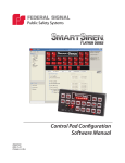
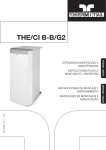
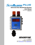
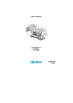
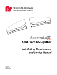
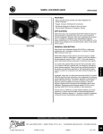
1
LED JetSolaris® Lightbar
with ROC™ Technology
JLX 48”, 54”, 60”, and 72” Series
TM
Installation and Service Manual
2562335C
REV. C 512
Printed in U.S.A.
3
Contents
Chapter 1: Safety Messages.......................................................................................... 5
Safety Messages to Installers and Service Personnel of Warning Light Equipment................. 5
Safety Message to Operators of Warning Light Equipment................................................. 8
Chapter 2: An Overview of the JLX JetSolaris............................................................... 10
Product Overview.......................................................................................................10
Lightbar Specifications................................................................................................10
Unpacking the Product................................................................................................11
Before You Begin........................................................................................................11
Chapter 3: Installing the JLX JetSolaris....................................................................... 12
Connecting the Power Leads for the Standard JLX...........................................................12
Control Wires For the Standard JLX Lightbar..................................................................13
Control Wires for the UNICOR® JLX Lightbar...................................................................15
Wiring the Controls for White Light and Front/Rear Cutoff
(Except Lightbars with 23-Pin Shell Connectors).............................................................16
Selecting Flash Patterns for Primary and Secondary Mode................................................16
Testing the System.....................................................................................................20
Chapter 4: Installing the SignalMaster (Option)........................................................... 22
Assembling and Mounting the Control Head...................................................................22
Wiring the Control Head..............................................................................................23
Operating the Control Head.........................................................................................24
Chapter 5: Installing the Solar Panel Charging System (Option)................................. 25
An Overview of the Solar Panel Charging System............................................................25
Product Specifications.................................................................................................25
Mounting the Charger.................................................................................................26
Wiring the Solar Panel Charging System........................................................................26
Chapter 6: Servicing the Lightbar................................................................................ 28
Establishing a Maintenance Schedule............................................................................28
Cleaning the Plastic Domes..........................................................................................28
Cleaning the Reflectors...............................................................................................29
Replacing the Halogen Lamps.......................................................................................29
Aiming the Halogen Lamps..........................................................................................32
Replacing an End Board...............................................................................................33
Replacing the Control Board.........................................................................................35
Replacing a Fuse........................................................................................................36
Replacing a Center Board............................................................................................37
Replacing the Solar Panel............................................................................................38
Chapter 7: Ordering Parts and Service........................................................................ 39
Getting Technical Support and Service...........................................................................39
Ordering Replacement Parts.........................................................................................39
Returning a Product to Federal Signal............................................................................39
4
Contents
Tables
Table 3.1: 9-conductor cable wires (12 AWG) (Standard JLX)...............................................14
Table 3.2: 11-conductor cable wires (12 AWG) (Standard JLX).............................................14
Table 3.3: 23-conductor cable wires (12 AWG) (UNICOR)....................................................15
Table 3.3: 23-conductor cable wires (12 AWG) (UNICOR) (continued)...................................16
Table 3.4: Lightbar Flash Patterns for Standard JLX ROC Lightbars........................................19
Table 4.1: SignalMaster control cable wires.........................................................................24
Figures
Figure 3.1: Location (circles) of screws securing end dome..................................................18
Figure 3.2: Location (circle) of S1 PROGRAM button............................................................19
Figure 4.1: SignalMaster control head................................................................................22
Figure 4.2: Connections for SignalMaster control head..........................................................24
Figure 6.1: Halogen worklight and takedown replacement types...........................................31
Figure 6.2: Alley lamp replacement PN 8107241.................................................................32
Figure 6.3: Adjustment screw for aiming the halogen lamp..................................................33
Figure 6.4: Center board and end board exploded view.......................................................34
Figure 6.5: Control board removed from bracket.................................................................36
Figure 6.6: Solar panel....................................................................................................38
5
Chapter 1: Safety Messages
In this chapter:
■
Safety Messages to Installers and Service Personnel of Warning Light Equipment
■
Safety Message to Operators of Warning Light Equipment
Safety Messages to Installers and Service Personnel of Warning
Light Equipment
People’s lives depend on your proper installation and servicing of Federal Signal
products. It is important to read and follow all instructions shipped with this product.
In addition, listed below are some other important safety instructions and precautions
you should follow:
Before Installation or Service
Qualifications
•
To properly install or service this equipment, you must have a good understanding of
automotive mechanical and electrical procedures and systems along with proficiency in the
installation and service of safety warning equipment. Always refer to the vehicle service
manuals when performing equipment installations on a vehicle.
Light Hazards
•
To be an effective warning device, this product produces bright light that can be hazardous
to your eyesight when viewed at a close range. Do not stare directly into this lighting
product at a close range or permanent damage to your eyesight may occur.
•
Do not install the light system in an area that would block, impair, or blind the driver’s
vision. Ensure that the light system is mounted in a position that is outside of the driver’s
field of vision, so the driver can safely operate the vehicle.
•
Federal Signal power supplies and light heads are designed to work together as a system.
Combining light heads and a power supply from different manufacturers may reduce the
warning effectiveness of the lighting system and may damage the components. You should
verify or test your combination to ensure the system works together and meets federal,
state, and local standards or guidelines.
Electrical Hazards
•
Strobe systems present a shock hazard because they use high voltage to operate. Do not
handle strobe cables, the power supply, or bulbs or remove the lens while the equipment
is connected. Strobe systems can also hold their charge even after they have been turned
6
Chapter 1: Safety Message to Installers and Service Personnel
off. After disconnecting power to the unit, wait five minutes before handling any parts of the
strobe system.
•
A light system is a high current system. In order for the system to function properly, a
separate negative (–) connection and positive (+) connection must be made. All negative
connections should be connected to the negative battery terminal and a suitable fuse
should be installed on the positive battery terminal connection as close to the battery
as possible. Ensure that all wires and fuses are rated correctly to handle the device and
system amperage requirements.
•
Never attempt to install aftermarket equipment that connects to the vehicle wiring without
reviewing a vehicle wiring diagram available from the vehicle manufacturer. Ensure that
your installation will not affect vehicle operation or mandated safety functions or circuits.
Always check the vehicle for proper operation after installation.
•
The lighting system components, especially light bulbs, strobe tubes, LEDs, and the outer
housing, get hot during operation. Be sure to disconnect power to the system and allow the
system to cool down before handling any components of the system.
•
Halogen light bulbs and strobe tubes are pressurized and if broken, can burst and result in
flying glass. Always wear gloves and eye protection when handling these components.
•
Do not mount a radio antenna within 18 inches (45.7 cm) of the lighting system. Placing
the antenna too close to the lighting system could cause the lighting system to malfunction
or be damaged by strong radio fields. Mounting the antenna too close to the lighting system
may also cause the radio noise emitted from the lighting system to interfere with the
reception of the radio transmitter and reduce radio reception.
•
Do not attempt to wash any unsealed electrical device while it is connected to its power
source.
During Installation and Service
•
DO NOT get metal shavings inside the product. Metal shavings in the product can cause the
system to fail. If drilling must be done near the unit, place an ESD-approved cover over the
unit. Inspect the unit after mounting to be sure there are no shavings present in or near
the unit.
•
DO NOT connect this system to the vehicle battery until ALL other electrical connections are
made, mounting of all components is complete, and you have verified that no shorts exist.
If the wiring is shorted to the vehicle body or frame, high current conductors can cause
hazardous sparks resulting in electrical fires or flying molten metal.
•
DO NOT install equipment or route wiring (or the plug-in cord) in the deployment path of an
airbag.
•
Before mounting any components, check the manual to be sure that the component you are
installing is suitable for use in that area of the vehicle. Many components are not suitable
for use in the engine compartment or other extreme environmental exposure areas.
•
Service life of light bulbs and strobes tubes will be shortened if the glass portion is touched
during installation. Use gloves when handling these components. If the glass portion has
been touched, clean the glass carefully with isopropyl alcohol.
Chapter 1: Safety Message to Installers and Service Personnel
•
When drilling into a vehicle structure, be sure that both sides of the surface are clear of
anything that could be damaged. Remove all burrs from drilled holes. To prevent electrical
shorts, grommet all drilled holes through which wiring passes. Also, ensure that the
mounting screws do not cause electrical or mechanical damage to the vehicle.
•
Refer to the manual packed with the lighting system for proper electrical connections,
additional precautions, and information.
•
Because vehicle roof construction and driving conditions vary, do not drive a vehicle with
a magnetically mounted warning light installed. The light could fly off the vehicle causing
injury or damage. Repair of damage incurred because of ignoring this warning shall be the
sole responsibility of the user.
•
To avoid denting the roof of the vehicle, place the lightbar mounting feet as close to the
outer edge of the roof as possible.
•
Roof damage can occur if the hook adjustment bolts are over-tightened. Tighten
adjustment bolts 10 to 11 ft-lb to prevent the lightbar from sliding front-to-back when
pulling on the mounting bracket.
•
Locate the light system controls so the VEHICLE and CONTROLS can be operated safely
under all driving conditions.
After Installation or Service
•
After installation, test the light system to ensure that it is operating properly.
•
Test all vehicle functions, including horn operation, vehicle safety functions, and vehicle
light systems, to ensure proper operation. Ensure that the installation has not affected the
vehicle operation or changed any vehicle safety function or circuit.
•
Scratched or dull reflectors, mirrors, or domes will reduce the effectiveness of the
lighting system. Avoid heavy pressure and use of caustic or petroleum based products
when cleaning the lighting system. Replace any optical components that may have been
scratched or crazed during system installation.
•
Do not attempt to activate or de-activate the light system control while driving in a hazardous
situation.
•
You should frequently inspect the light system to ensure that it is operating properly and
that it is securely attached to the vehicle.
•
After installation and testing are complete, provide a copy of these instructions to
instructional staff and all operating personnel.
•
File these instructions in a safe place and refer to them when maintaining or re-installing
the product.
Failure to follow all safety precautions and instructions may result in property
damage, serious injury, or death to you or others.
RETAIN AND REFER TO THIS MESSAGE
7
8
Chapter 1: Safety Message to Installers and Service Personnel
Safety Message to Operators of Warning Light Equipment
People’s lives depend on your safe use of our products. Listed below are some
important safety instructions and precautions you should follow:
•
Do not attempt to activate or de-activate the light system control while driving in a hazardous situation.
•
Although your warning system is operating properly, it may not be completely effective.
People may not see or heed your warning signal. You must recognize this fact and continue
driving cautiously.
•
Also, situations may occur which obstruct your warning signal when natural and man-made
objects are between your vehicle and others, such as raising your hood or trunk lid. If these
situations occur, be especially careful.
•
All effective sirens and horns produce loud sounds that may cause, in certain situations,
permanent hearing loss. You and your passengers should consider taking appropriate safety
precautions, such as wearing hearing protection.
•
In order to be an effective warning device, this product produces bright light that can be
hazardous to your eyesight when viewed at a close range. Do not stare directly into this
lighting product at a close range or permanent damage to your eyesight may occur.
•
It is important that you fully understand how to safely operate this warning system before
use.
•
You should only operate your vehicle and its light/sound system in accordance with your
department’s Standard Operating Procedures.
•
If a selected function does not perform properly or if any of the lamps remain illuminated
when the control is off, disconnect the power connector from the control unit and contact
the nearest service center.
•
At the start of your shift, you should ensure that the entire warning light system and the
siren system is securely attached and operating properly.
•
Suction cup mounting is for temporary applications only. The unit should be removed from
the window and stored securely when not in use. Temperature changes and sunlight can
cause suction cups to lose holding power. Periodically check the unit to be sure the suction
cups have a firm grip on the mounting surface. An improperly secured light could fall off of
the vehicle causing injury and damage.
•
Holding power of magnetic mounting systems is dependent upon surface finish, surface flatness, and thickness of the steel mounting surface. Therefore, to promote proper magnetic
mounting:
✓
Mounting surface and magnets must be kept clean, dry, and free of foreign particles that
prevent good surface contact.
✓
Ensure that mounting surface is flat.
Chapter 1: Safety Message to Installers and Service Personnel
✓
A magnet mounting system should not be used on vehicles with vinyl tops.
✓
To prevent sliding of light assembly on mounting surface, quick acceleration and hard
stops should be avoided.
Failure to follow these precautions may result in property damage, serious injury, or
death to you, to passengers, and to others.
RETAIN AND REFER TO THIS MESSAGE
9
10
Chapter 2: An Overview of the JLX JetSolaris
In this chapter:
■
Product Overview
■
Lightbar Specifications
■
Unpacking the Product
■
Before You Begin
Product Overview
The JetSolaris® is an LED lightbar that can be used in a variety of applications for Fire/Rescue,
Police, DOT, and Tow/Recovery. The JetSolaris features the latest in Solaris® LED and ROC
(Reliable Onboard Circuitry) technology. ROC substantially reduces wiring and connections
with its consolidated design of printed circuit boards, and the Solaris LED reflectors provide
maximum LED performance. Solaris LED and ROC technology improves the performance and
virtually eliminates any maintenance while being supported by a five year warranty on the LED
components.
The standard JetSolaris comes with 40 selectable flash patterns, including a test pattern. The
LEDs are available in amber, blue, red, white, and green. Dome colors are available in amber,
blue, red, and clear. Halogen worklight options are also available.
Lightbar Specifications
Dimensions (H x L x W):
JLX 48"
4.7 in x 47.5 in x 11.2 in (119 mm x 1207 mm x 284 mm)
JLX 54"
4.7 in x 54 in x 11.2 in (119 mm x 1372 mm x 284 mm)
JLX 60"
4.7 in x 60 in x 11.2 in (119 mm x 1524 mm x 284 mm)
JLX 72"
4.7 in x 72 in x 11.2 in (119 mm x 1829 mm x 284 mm)
Current Draw:
Three-button Solaris LED 0.5 A
reflector (any color)
Six-button Solaris LED
reflector (any color)
1.0 A
Traffic Clearing Light:
4.3 A
Halogen Worklight:
4.0 A
Stop/Tail/Turn Light:
0.32 A
Voltage:
12 Vdc
Cable Length:
15 ft (457.2 cm)
Chapter 2: An Overview of the JLX JetSolaris
Shipping Weight:
JLX 48"
32.0 lb (14.5 kg)
JLX 54"
33.5 lb (14.2 kg)
JLX 60"
35.0 lb (16.3 kg)
JLX 72"
38.0 lb (17.2 kg)
Approvals:
NFPA 1901 compliant models are available.
SAE J1318, J595, and J845 Class 1
Unpacking the Product
After unpacking the product, examine it for damage that may have occurred in transit. If the
product has been damaged, file a claim immediately with the carrier stating the extent of
damage. Carefully check all envelopes, shipping labels, and tags before removing or destroying
them.
Before You Begin
AIRBAG DEPLOYMENT
Locate the controls for the light system so that the vehicle and control can be operated
safely under all driving conditions.
Failure to heed this precaution could result in driver distraction or driver error while
operating the vehicle.
Before you begin, ensure that the lightbar has been installed on the vehicle roof according to the
instructions included with the mounting kit. An installer-supplied control head controls the basic
functions of the lightbar.
11
12
Chapter 3: Installing the JLX JetSolaris
In this chapter:
■
Connecting the Power Leads for the Standard JLX
■
Control Wires for the Standard JLX
■
Control Wires for the UNICOR® JLX Lightbar
■
Wiring the Controls for Front and Rear Light Cutoff (Except Lightbars with 23-Pin Shell Connectors)
■
Selecting Flash Patterns for Primary and Secondary Mode
■
Testing the System
Connecting the Power Leads for the Standard JLX
The lightbar is completely wired at the factory and does not require any additional internal
wiring. All the conductors necessary to control the lightbar’s functions are contained in the cable.
Installation of options requires additional wiring to the warning light system and vehicle battery.
An installer-supplied switch or relay rated at 30 A is required for the connection between the JLX
red power lead and the fused power source. If additional wire length is needed, splice wire of
the same gauge or heavier to the leads.
AIRBAG DEPLOYMENT
Do not install equipment or route wiring in the deployment path of an airbag.
Failure to observe this warning will reduce the effectiveness of the airbag, damage the
airbag or potentially dislodge the equipment, causing serious injury to you or others.
1.
Route the control cable into the vehicle and under the dash, near the eventual location of
the installer-supplied control head. Apply sealant to all drilled holes.
2.
For proper lightbar operation, the control cable must be properly terminated inside the installer-supplied control head. The current capacities of the switch for the control head should be
at least 15 A. See Tables 3.1 and 3.2 on page 10 for the wire colors and functions.
PROPER GROUNDING
The lightbar WILL NOT light up or flash if it is improperly grounded. Be sure that
the lightbar is connected to a good vehicle ground.
Failure to observe this warning can lead to equipment failure and may result in
serious injury or death to you or others.
Chapter 3: Installing the JLX JetSolaris
3.
Connect the black 10 AWG ground lead to a good battery or chassis ground.
SPARK HAZARD
If wires are shorted to the vehicle frame or each other, high current conductors
can cause hazardous sparks resulting in electrical fires and molten metal.
Verify that no short circuits exist before connecting to the positive (+) battery
terminal.
CURRENT CAPABILITY
To provide safe operation of the lightbar, the power control switch and wiring
must be capable of handling the rated current of the fuse at the source.
HIGH CURRENT ARCING
Do not connect this system to the vehicle battery until ALL other electrical
connections are completed, mounting of all components are complete, and you
have verified that no shorts exist.
High current shorts can cause hazardous sparks or burning wire resulting in an
electrical fire.
FUSE ELECTRICAL SOURCES
Always fuse the current/voltage sources with a fuse connected near the power
source. Be sure that the fuse is properly rated to protect the electrical load, the
wiring, and the connectors in the circuit.
Failure to follow this notice could result in vehicle or equipment damage.
4.
Connect the red 10 AWG power lead from the lightbar to an installer-supplied switch or relay rated at 30 A.
5.
Connect the other side of the fuse/circuit breaker to the +12 Vdc supply.
NOTE: The driver and passenger sides of the lightbar are individually and internally fused
with a 15 A fuse located on the lightbar control board at F3 and F4. See "Replacing a Fuse"
on page 32.
Control Wires For the Standard JLX Lightbar
All of the lightbar controls are integrated in the ROC PC board. Lightbars are manufactured with
either a 9-conductor control cable or a 11-conductor control cable. See Tables 3.1 and 3.2 on
page 10 for the functions of the control wires. You can activate any of the lightbar functions by
applying 12 Vdc to the wire that controls the function.
13
14
Chapter 3: Installing the JLX JetSolaris
For information on the option to enable the lightbar to cut off certain lights, see “Wiring the
Controls for White Light and Front/Rear Cutoff (Except Lightbars with 23-Pin Shell Connectors”
on page 12.
Table 3.1: 9-conductor cable wires (12 AWG) (Standard JLX)
Wire Color**
Function
Red*
PRIMARY MODE: +12 Vdc: Activates the lightbar in Primary Mode. For a
description of Primary Mode, see page "Selecting Flash Patterns for Primary
and Secondary Mode" on page 12.
Black
GND (–): Connects to a good battery/chassis ground.
Gray
Takedown lights, traffic clearing light, worklights, or SignalMaster left
directional lights.
Green
Front light cutoff, rear light cutoff, or SignalMaster center-out directional lights.
Blue*
SECONDARY MODE: Applying +12 Vdc changes the pattern of the lightbar
to the pattern selected for Secondary Mode. The function is only active if the
lightbar is flashing in Primary Mode. For a description of Secondary Mode, see
page "Selecting Flash Patterns for Primary and Secondary Mode" on page 12.
Orange
PROGRAM (for Primary Mode): Applying GND (–) advances the flash pattern
to the next pattern in the library and stores it in memory. For a description of
the flash patterns, see Table 3.4 on page 15 for the flash patterns.
Yellow
WHITE LIGHT CUTOFF: Used only in lightbars that have white light in the
front positions. White lights flash with the rest of the lightbar when +12 Vdc
is applied to the yellow wire. White lights are cut off when disconnected or
power is removed. See "Wiring the Controls for White Light and Front/Rear
Cutoff (Except Lightbars with 23-Pin Shell Connectors" on page 12. If the wire
is not used for white light cutoff, other options are takedown lights, traffic
clearing lights, or worklights.
Brown
Driver-side alley light, driver-side stop/turn/tail light, steady burn lights,
worklights, driver traffic clearing light.
Brown/White
Passenger-side alley light. If there is no alley light option, the wire is used for
SignalMaster right directional lights, passenger side stop/turn/tail lights, or the
passenger-side traffic clearing light.
Table 3.2: 11-conductor cable wires (12 AWG) (Standard JLX)
Wire Color
Function
Red*
PRIMARY MODE: +12 Vdc: Activates the lightbar in Primary Mode. For a
description of Primary Mode, see page 12.
Black
GND (–): Connects to a good battery/chassis ground.
Gray
Takedown, traffic clearing light, worklight, or SignalMaster left directional lights.
Green
Front light cutoff, rear light cutoff, driver-side stop/turn/tail lights, steady burn,
or SignalMaster center out directional lights.
Blue*
SECONDARY MODE: Applying +12 Vdc changes the pattern of the lightbar to
the pattern selected for Secondary Mode. Only active if the lightbar is normally
flashing in Primary Mode. For a description of Secondary Mode, see page 12.
Orange
PROGRAM for Primary Mode: Applying GND (–) advances the flash pattern to
the next pattern in the library and stores it in memory. For a description of the
flash patterns, see Table 3.4 on page 15.
continues on next page
Chapter 3: Installing the JLX JetSolaris
Table 3.2: 11-conductor cable wires (12 AWG) (Standard JLX) (continued)
Yellow
WHITE LIGHT CUTOFF: Used only in lightbars that have white light in the front
three positions. White lights flash with the rest of the lightbar when +12 Vdc
is applied to the yellow wire. White lights are cut off when disconnected or
power is removed. See "Wiring the Controls for White Light and Front/Rear
Cutoff (Except for Lightbars with 23-Pin Shell Connectors" on page 12. If the
wire is not used for white light cutoff, other options are takedown lights, traffic
clearing lights, or worklights.
Brown
Driver-side brake, turn, or alley lights.
Brown/White
Passenger-side brake, turn, alley light, or passenger-side traffic clearing light.
Black/White
Tail lights, takedown lights, traffic clearing lights, or worklights.
Red/White
SignalMaster right directional lights, passenger-side stop/turn/tail lights, or both
alleys simultaneously.
*The red and blue wires also serve as programming wires for Secondary Mode. See
"Programming Secondary Mode" on page 13.
** The wire color for a function (with the exceptions of the red, blue, and orange wires) may
vary depending on the configured options in the lightbar.
Control Wires for the UNICOR® JLX Lightbar
Custom JLX Lightbars built for UNICOR have wiring that is terminated in a 23-pin shell
connector. Table 3.3 describes the wires from the connector to the lightbar.
Table 3.3: 23-conductor cable wires (12 AWG) (UNICOR)
Number
Letter
Wire Color
1
A
Open
2
B
Open
Function
3
C
Open
4
D
Black
Chassis ground to the lightbar
5
E
Black
Chassis ground to the lightbar
6
F
Black
Chassis ground to the lightbar
7
G
Black
Chassis ground to the lightbar
8
H
Red
Red wire to solar panel
9
J
Red with white stripe
Front of lightbar
10
K
Red with black stripe
Steady burn
11
L
Open
12
M
Blue
13
N
Open
14
P
Yellow
15
R
Open
16
S
Orange with black stripe
17
T
Open
18
U
Orange
Right alley
19
V
Green with black stripe
Rear of lightbar
Takedowns
Yellow wire to solar panel
Left alley
continues on next page
15
16
Chapter 3: Installing the JLX JetSolaris
Table 3.3: 23-conductor cable wires (12 AWG) (UNICOR) (continued)
20
W
Open
21
X
Open
22
Y
Open
23
Z
Black
Black wire to solar panel
Wiring the Controls for White Light and Front/Rear Cutoff
(Except Lightbars with 23-Pin Shell Connectors)
The standard lightbar can be configured when ordered from the factory with options that turn
off white lights or turn off the front or rear of the lightbar. The options are controlled by applying
and removing power to the control wire of the function in the lightbar’s cable.
White Light Cutoff
The option to cut off the standard lightbar’s white lights is set at the factory with dip
switches on the lightbar's control board. The cable’s yellow wire controls White Light Cutoff.
When +12 Vdc is applied to the wire, the white lights flash in the same flash pattern as the
rest of the lightbar. When +12 Vdc is removed from the wire, the white lights turn off. If
white light cutoff is not needed, fold and insulate the wire.
Front or Rear Light Cutoff
The lightbar may be equipped to shut off the front of the lightbar or the rear of the lightbar,
while the rest of the lightbar is still flashing. The option is controlled by the green wire in the
lightbar control cable. When +12 Vdc is applied to the wire, the lights flash. When +12 Vdc
is removed from the wire, the lights shut off. If front or rear light cutoff is not needed, fold
and insulate the wire.
Selecting Flash Patterns for Primary and Secondary Mode
Although the standard JetSolaris is shipped with preselected flash patterns for Primary and
Secondary Mode, you can select new patterns from the lightbar internal library of 40 flash
patterns. A pattern displayed in Primary Mode is typically more active than the pattern displayed
in Secondary Mode. It indicates the primary purpose of the vehicle; for example, the vehicle is
on its way to the scene of an emergency or is towing a car. A pattern displayed in Secondary
Mode is a more relaxed pattern, indicating that the vehicle is returning from the scene.
The default pattern in Primary Mode is Pattern 1, Alternating Quad Flash 76 QFPM. In Secondary
Mode, it is Pattern 2, Overlapping Penta Flash 87 FPM. Table 3.4 on page 15 lists the flash
patterns in the lightbar pattern library.
We recommended that you select flash patterns for both Primary and Secondary Mode during
the installation of the lightbar. There are two methods of selecting a flash pattern for Primary
and Secondary Mode. One method enables you to directly apply ground or 12 Vdc power to
wires in the lightbar control cable. This method is best suited for a lightbar not yet connected to
a control head. The other method enables you to press a mode button on the control head and
select a pattern using a programming button inside the lightbar. The two methods are described
in the next sections. For descriptions of the control wires, see Tables 3.1 and 3.2 on page 10.
Chapter 3: Installing the JLX JetSolaris
NOTE: To return to the default flash pattern while programming Primary or Secondary Mode
using the control wire method, apply GND (–) to the orange wire for 5 seconds.
Programming Primary Mode
Table 3.4 on page 15 lists the flash patterns in the lightbar library.
1.
Apply +12 Vdc to the Primary (red) wire in the lightbar cable.
2.
Apply GND (–) to the orange wire in the lightbar cable.
LIGHT HAZARDS
To be an effective warning device, this product produces bright light that can
be hazardous to your eyesight when viewed at a close range. Do not stare
directly into this lighting product at a close range or permanent damage to
your eyesight may occur.
3.
When the pattern changes, disconnect the orange wire for a few seconds and observe
the pattern. To display the next pattern in the library, apply and remove GND (–) to the
orange wire.
4.
To select the pattern, allow it to run for at least 15 seconds to set it in memory.
Programming Secondary Mode
Table 3.4 on page 15 lists the flash patterns in the lightbar library
1.
Apply +12 Vdc to both the Primary (red) and Secondary (blue) Mode wires to turn on
the lightbar in Secondary Mode.
2.
Apply GND (–) to the orange wire in the lightbar cable.
LIGHT HAZARDS
To be an effective warning device, this product produces bright light that can
be hazardous to your eyesight when viewed at a close range. Do not stare
directly into this lighting product at a close range or permanent damage to
your eyesight may occur.
3.
When the pattern changes, disconnect the orange wire for a few seconds and observe
the pattern. To display the next pattern in the library, apply and remove GND (–) to the
orange wire.
4.
To select a pattern, allow it to run for at least 15 seconds to save it in memory.
17
18
Chapter 3: Installing the JLX JetSolaris
Programming with the PROGRAM Pushbutton
The S1 PROGRAM pushbutton is on the underside of the passenger-side end PCB directly
below the label "PROGRAM" silkscreened on the top of the board (Figure 3.2 on page 15).
Table 3.4 on page 15 lists the flash patterns in the lightbar’s library
STATIC-SENSITIVE DEVICE
This product's circuitry can be damaged by electrostatic discharge (ESD). Follow
anti-static procedures while installing this product.
NOTE: To return to the default flash pattern while programming Primary or Secondary Mode
using the pushbutton method, apply GND (–) to the orange wire for 5 seconds.
1.
Use a large flat-head screwdriver to remove the two 1/4-20 screws that secure the
passenger side end dome to the aluminum extrusion (Figure 3.1) and remove the
nameplate.
Figure 3.1: Location (circles) of screws securing end dome
2.
Slide the end dome off the aluminum extrusion.
3.
Apply power to flash the lightbar in Primary Mode.
LIGHT HAZARDS
To be an effective warning device, this product produces bright light that can
be hazardous to your eyesight when viewed at a close range. Do not stare
directly into this lighting product at a close range or permanent damage to
your eyesight may occur.
4.
Press the S1 PROGRAM button on the underside of the passenger-side end PCB (Figure
3.2 on page 15). The lightbar turns off momentarily and flashes the next pattern. When
the pattern changes, observe the pattern.
Chapter 3: Installing the JLX JetSolaris
TOP OF
PASSENGER SIDE
END PCB
BOTTOM OF
PASSENGER SIDE
END PCB
Figure 3.2: Location (circle) of S1 PROGRAM button
5.
To see the next pattern in the library, press the PROGRAM button until the lightbar
again changes patterns.
6.
To select a pattern, allow it to run for at least 15 seconds to save it in memory.
Table 3.4: Lightbar Flash Patterns for Standard JLX ROC Lightbars
Pattern
Description
Pattern 1*
175 Alternating Single
Pattern 2*
Overlapping Penta Flash—87 FPM
Pattern 3*
Overlapping Alternating—95 FPM
Pattern 4*
Alternate Quad Flash—76 QFPM
Pattern 5*
Simultaneous/Overlapping Triple/Nine
Pattern 6
Alternating Single
Pattern 7
640 FPM Overlapping With Overlap 5/2
Pattern 8
2 at 60 FPM 4 Pulse Alternating, then 2 at 60 FPM 2 Pulse Simultaneous
Pattern 9
Driver-Side End Rear Alt with Passenger-Side End Rear—120 Single FPM
Pattern 10
Driver Side End Rear Alt with Passenger Side End Rear—90 Single FPM
Pattern 11
Driver-Side End Rear Alt with Passenger-Side End Rear Alternate with Center
Rear—80 Double FPM
Pattern 12
Driver-Side / Passenger-Side Center Rear Alternate with Center Rear/Driver and
Passenger Ends—80 Double FPM
Pattern 13
Lightheads Oscillate In/Out
Pattern 14
Driver and Passenger Front Ends Alt with Center Front
Pattern 15
Driver and Passenger Front Ends Alt with Center Front Followed by Center Front
Alt with Driver and Passenger Front Ends—80 Double FPM
Pattern 16
Wraparound Inside to Outside
Pattern 17
Wraparound Inside to Outside to Inside Followed by Wig/Wag Alt Flash
Pattern 18
Wig/Wag Driver-Side Front Alt with Passenger Side Front
Pattern 19
In Tow Mode Pattern 1—Mode 2, Pattern 1
continues on next page
19
20
Chapter 3: Installing the JLX JetSolaris
Table 3.4: Lightbar Flash Patterns for Standard JLX ROC Lightbars (continued)
Pattern 20
In-Tow Mode Pattern 2—Mode 2, Pattern 2
Pattern 21
In-Tow Mode Pattern 3—Mode 2, Pattern 3
Pattern 22
Flash—Mode 2, Pattern 4
Pattern 23
Quad—Wraparound In-Out—Full Quad
Pattern 24
Wraparound In-Out—40 mS Per Lighthead
Pattern 25
Wig/Wag Driver-Side Front Alt with Passenger Side Front Followed by Alt Flash
Pattern 26
Quad Flash
Pattern 27
Wraparound Inside to Outside to Inside Followed by Wig/Wag Alt Flash Followed
by Full Quad Flash
Pattern 28
Wraparound Inside to Outside to Inside Followed by a Quad Flash
Pattern 29
Double Flash of Pairs Followed by a Quad Flash of Pairs and End Caps
Pattern 30
Quadrant Flash Followed by Wraparound Inside to Outside Followed by a Triple
Full Flash
Pattern 31
Increasing-Rate Alt Flash Followed by a Triple Full Flash
Pattern 32
Alternate Triple Flash of Entire Lightbar
Pattern 33
Double Flash Driver and Passenger Front with Driver and Passenger Rear
Pattern 34
Double Flash Driver and Passenger Front with Driver and Passenger Rear
Followed by Wraparound Inside to Outside
Pattern 35
Double Flash Driver and Passenger Front Wraparound In-Out Followed by Double
Flash of Driver and Passenger Rear Wraparound Out-In
Pattern 36
Wraparound In-Out, Alt Double Flash, Wraparound Out-In, Full Quad Flash
Pattern 37
Full Quad Flash, Wraparound Out-In, Alt Double Flash, Wraparound In-Out
Pattern 38
Alternate Triple Flash Entire Lightbar Twice, Wraparound In-Out, Alt Double
Flash, Wraparound In-Out
Pattern 39*
Alternating 90 FPM
Pattern 40
Test Pattern—Rotate Entire Lightbar 750 mS Per Head
* Denotes that the pattern is SAE compliant.
Testing the System
SOUND HAZARD
All effective sirens and horns produce loud sounds (120 dB) that may cause
permanent hearing loss. Always minimize your exposure to siren sound and wear
hearing protection. Do not sound the siren indoors or in enclosed areas where you and
others will be exposed to the sound.
After the installation, test the emergency warning system to ensure that it is operating properly.
Also test all vehicle functions, including horn operation, vehicle safety functions, and vehicle
lighting systems to ensure proper operation. Ensure that the installation has not affected the
vehicle operation or changed any vehicle safety functions or circuits. After testing is complete,
provide a copy of these instructions to the instructional staff and all operating personnel.
Chapter 3: Installing the JLX JetSolaris
Do not test the sound and light system of the vehicle while driving. Operating the vehicle
warning systems may pose a hazard to the operator and other drivers if the systems do not
function as expected. Test the vehicle only in a controlled environment.
21
22
Chapter 4: Installing the SignalMaster (Option)
In this chapter:
■
Assembling and Mounting the Control Head
■
Wiring the Control Head
■
Operating the Control Head
Assembling and Mounting the Control Head
AIRBAG DEPLOYMENT
Do not install equipment or route wiring in the deployment path of an airbag.
Failure to observe this warning will reduce the effectiveness of the airbag, damage the
airbag or potentially dislodge the equipment, causing serious injury to you or others.
The SignalMaster option includes a control head with a cable that has five 22 AWG leads and one
18 AWG jumper wire. If additional wire length is need, splice wire of the same gauge or heavier
to the leads.
1.
Assemble the control head as shown in Figure 4.1. The switches must be installed as shown
for the control head to operate properly. Two installer-supplied sheet-metal screws are required for mounting the control head.
22 AWG CHASSIS
GROUND LEAD FROM
SIGNALMASTER
SWITCH
BRACKET
NOTE:
GOLD
(NO. 3)
TERMINAL
ON TOP
F
A
IGN
LS
RA
E
ED
ION
AT
OR
RP
O
LC
D
R
ZA
SWITCH
ON/OFF/ON
HA
ON
F
OF
DECAL
RED
SWITCH ON/OFF
Figure 4.1: SignalMaster control head
290A5308-01
Chapter 4: Installing the SignalMaster (Option)
NOTE: When selecting a mounting location for the control head, it is necessary to keep in mind
the SignalMaster’s cable length. Plan wiring and cable routing before installation.
1.
Select a mounting location for the control head that allows the vehicle and controls to be
operated safely at all times.
2.
Use the control head as a template and scribe two drill position marks at the selected
mounting location.
DRILLING PRECAUTIONS
Before drilling holes, check the area into which you plan to drill to ensure you do
not damage vehicle components while drilling. All drilled holes should be deburred
and all sharp edges should be smoothed. All wires going through drilled holes
should be protected by a grommet or convolute/split-loom tubing.
3.
Drill a hole at each drill-position mark.
4.
Secure the control head to the mounting surface with two installer-supplied sheet metal
screws.
Wiring the Control Head
SPARK HAZARD
If wires are shorted to the vehicle frame or each other, high current conductors can
cause hazardous sparks resulting in electrical fires and molten metal.
Verify that no short circuits exist before connecting to the positive (+) battery terminal.
HIGH CURRENT ARCING
Do not connect this system to the vehicle battery until all other electrical connections
are completed, mounting of all components is complete, and you have verified that no
shorts exist.
High-current shorts can cause hazardous sparks or burning wire resulting in an
electrical fire.
1.
Wrap the control cable’s stripped wire ends with tape and route the cable to the control
head mounting location.
2.
Crimp the 1/4-inch FASTON terminals on the ends of the cable leads.
3.
Connect the terminals on the switch as shown in Figure 4.2 on page 20.
4.
Ensure that there are no loose wire strands or other bare wires that may cause a short
circuit. All wires must be protected from any sharp edges that could eventually cut through
the insulation.
23
24
Chapter 4: Installing the SignalMaster (Option)
SWITCH BRACKET
REAR VIEW
HAZARD
SWITCH
CHASSIS GROUND
BROWN
WHITE
3
1
2
3
BLACK
RED
2
OFF-ON
SWITCH
GOLD
TERMINAL
1
RED
GREEN
NOTE: TWO WIRES ARE
CRIMPED IN ONE TERMINAL
JUMPER WIRE FROM
INSTALLATION KIT
CONTROL CABLE
ASSEMBLY
NOTE: MATING FEMALE TERMINALS ARE CRIMPED
ON WIRES BEFORE CONNECTING TO SWITCHES.
CAUTION
IMPROPER WIRING OF THE ILLUMINATED SWITCH FEATURE
WILL RESULT IN P.C.B. DAMAGE. ENSURE THAT THE CHASSIS GROUND
LEAD (22 AWG BROWN) IS CONNECTED TO THE GOLD (PIN #3) TERMINAL.
290A5309-01
Figure 4.2: Connections for SignalMaster control head
Table 4.1: SignalMaster control cable wires
Color
Description
Red
+12 Vdc
Brown
Chassis
Green
Center Out directional pattern
White
Left arrow directional pattern
Black
Right arrow directional pattern
White/Green
Not used
Operating the Control Head
The control head has a power switch and a rocker switch that enables the operator to select
SignalMaster patterns.
ON/OFF Switch
When the control head's power switch is in the ON position, the LED in the switch turns on.
If the LED does not turn on, check the ground lead on the control head's mounting bracket
properly grounded to the vehicle chassis.
Rocker Switch
The patterns the switch positions display override the turn signal/brake option.
LEFT position: Displays a left-arrow flashing pattern, directing traffic to proceed around the
vehicle to the left.
CENTER position: The middle lights alternate with two outer lights on each side.
RIGHT position: Displays right-arrow flashing pattern, directing traffic to proceed around the
vehicle to the right.
25
Chapter 5: Installing the Solar Panel Charging System
(Option)
In this chapter:
■
An Overview of the Solar Panel Charging System
■
Product Specifications
■
Mounting the Charger
■
Wiring the Solar Panel Charging System
An Overview of the Solar Panel Charging System
The Solar Panel Charging System comprises a solar panel mounted inside the lightbar and a
charger that is mounted near the vehicle battery with installer-supplied hardware. The system
has two functions:
•
It provides a charge to the battery to offset parasitic loads on the lead-acid vehicle battery,
such as a radio, computer, or alarm. These key-off loads drain the battery even when the
ignition is turned off.
•
It provides a constant electronic direct-current pulse that removes lead sulfates on the
lead-acid vehicle battery. Cleaning the battery plates of sulfates helps batteries maintain
maximum power and extends battery life.
IMPORTANT: For the Solar Panel Charging System to be effective, the vehicle must be parked
in an area exposed to DIRECT SUNLIGHT.
Although the Solar Panel Charging System is inside the lightbar, it is not electrically connected
to the lightbar electronics. Instead, it has a 28 ft. 3-conductor cable exiting the bottom of the
lightbar that you splice to the same color leads from the charger during the lightbar installation.
The charger also has 33-inch power leads with ring terminals that you will connect to the vehicle
battery.
Product Specifications
Battery Type:
Lead acid (flooded, AGM, gel cell)
Poise Frequency:
22–28 kHz: Extends battery life by cleaning
battery plates of large, damaging lead sulfates
Max. Charging DC Voltage:
16.5 V, 365 mA
Charger Dimensions
(H x L x W):
3.25 in x 2.25 in x 1.5 in
(82.6 mm x 57.2 mm x 38.1 mm)
Reverse polarity protected
26
Chapter 5: Installing the Solar Panel Charging System (Option)
Mounting the Charger
The charger has two mounting tabs on the housing. The hardware to install the charger is
installer-supplied.
1.
Select a permanent mounting location for the charger near the battery that is protected
from the elements and is undisturbed by mechanics or other devices. The location also
must be close enough to the battery so that the 18 AWG 33" red and black power leads
from the charger can be connected to the battery without splicing.
DO NOT MOUNT Charger ON BATTERY
Do not mount or fasten the charger directly to the surface of the battery.
Failure to heed this warning may damage the equipment or cause personal injury.
DRILLING PRECAUTIONS
Before drilling holes, check the area into which you plan to drill to ensure you do
not damage vehicle components while drilling. All drilled holes should be deburred
and all sharp edges should be smoothed. All wires going through drilled holes
should be protected by a grommet or convolute/split-loom tubing.
2.
To mount the charger, use the tabs as a template and mark two drill-position marks at the
mounting location.
3.
Use the installer-supplied hardware to secure the charger box to the mounting location.
Wiring the Solar Panel Charging System
AIRBAG DEPLOYMENT
Do not install equipment or route wiring in the deployment path of an airbag.
Failure to observe this warning will reduce the effectiveness of the airbag or
potentially dislodge the equipment, causing serious injury to you or others.
Installer-supplied connectors are required for splicing wires from the solar panel to the charger.
1.
Route the solar panel 28 ft cable through the vehicle toward the charger. Apply sealant to
all drilled holes.
SHOCK HAZARD
DO NOT hold the positive and negative ends of the terminal wires at the same
time if the solar panel is in sunlight as it can inflict an electric charge to the body.
Chapter 5: Installing the Solar Panel Charging System (Option)
SHORT CIRCUIT HAZARD
DO NOT hold the ends of the solar panel wires together while the panel is in
sunlight.
Failure to heed this notice will short out the output of the solar panel and can
cause the panel to fail.
DO NOT SPLICE LEADS TO BATTERY
Do not splice the leads between the charger and the battery. Increasing the lead
length will decrease the effectiveness of the charger.
2.
Remove excess cable and splice the 18 AWG red, yellow, and black wires from the lightbar
cable to wires of the same gauge and color in the charger cable.
HIGH-CURRENT ARCING
DO NOT connect this system to the vehicle battery until ALL other electrical
connections are completed, mounting of the components is complete, and you
have verified that no shorts exit.
High-current shorts can cause hazardous sparks or burning wire resulting in an
electrical fire.
DO NOT SPLICE CHARGER WIRES
Do not splice the leads between the charger and the battery, increasing the
distance from the charger to the battery. Increasing the lead length will decrease
the effectiveness of the charging module.
REVERSE POLARITY
The red positive (+) wire must be connected to the red positive (+) battery
terminal and the black negative (–) wire to the black (–) battery terminal.
Reversing connections could drain the battery.
3.
Remove the nut securing the battery clamp to the positive (+) battery terminal.
4.
Slip the ring terminal on the red positive (+) wire from the charger on the battery clamp
and securely tighten the nut onto the clamp.
5.
Remove the nut securing the battery clamp to the negative (+) battery terminal.
6.
Slip the ring terminal on the black negative (–) 18 AWG wire from the charger on the battery clamp and securely tighten the nut onto the clamp.
27
28
Chapter 6: Servicing the Lightbar
In this chapter:
■
Establishing a Maintenance Schedule
■
Cleaning the Plastic Domes
■
Cleaning the Reflectors
■
Replacing the Halogen Lamps
■
Aiming the Halogen Lamps
■
Replacing an End Board
■
Replacing the Control Board
■
Replacing a Fuse
■
Replacing a Center Board
■
Replacing the Solar Panel
Establishing a Maintenance Schedule
QUALIFICATIONS
To properly service a lightbar, you must have a good understanding of automotive
electrical procedures and systems along with proficiency in the installation and use of
safety warning equipment.
Establishing a regular maintenance schedule for the LED JLX extends the life of the lightbar
and ensures safety. Periodically check that the lightbar operates properly and that all mounting
hardware is securely fastened to the vehicle. Also, inspect the domes and reflectors for cracks,
crazing (hairline cracks), discoloration, and other defects.
This chapter has information for replacing components such as lamps, printed circuit boards
(PCBs) and fuses. For service, support, or replacement parts, contact the Federal Signal Service
Department at 1-800-433-9132, 7 am to 5 pm, Monday through Friday (CT).
Cleaning the Plastic Domes
CRAZING/CHEMICALS
Crazing (cracking) of domes will cause reduced effectiveness of the light. Do not
use cleaning agents (which will cause crazing) such as strong detergents, solvents,
or petroleum products. If crazing of domes does occur, the reliability of light for
emergency signaling purposes may be reduced until domes are replaced.
Chapter 6: Servicing the Lightbar
Failure to follow this warning can damage the domes and may result in bodily injury or
death to you or others.
1.
Rinse the domes with lukewarm water to loosen dirt and debris.
2.
Use a mild soap, lukewarm water, and a soft cloth to gently clean the domes. To avoid damaging the lens, do not use heavy pressure or caustic, abrasive, or petroleum-based cleaners.
3.
Rinse, then dry the domes with a soft cloth to prevent water spotting.
4.
To remove fine scratches and haze, use a specialty plastic cleaner/polish and a soft cloth.
You can also use a high quality automotive paste cleaner/wax that is non-abrasive.
The most effective product you can use for cleaning, protecting, and polishing clear and colored
plastics is Plexus® Plastic Cleaner, Protectant & Polish. Over time, exposure to heat, sunlight,
and smog causes plastic to fade, discolor, scratch, or become brittle. Plexus seals the pores
of the plastic, making the plastic easier to clean, improving scratch resistance, and increasing
product longevity. Plexus is available in cases of twelve 13-ounce cans (PX13) from Federal
Signal Corporation.
Cleaning the Reflectors
1.
Use a large flat-head screwdriver to remove the two 1/4-20 screws that secure the end
dome to the aluminum extrusion (Figure 3.1 on page 14) and remove the nameplate.
2.
Slide the end dome off the aluminum extrusion along with any additional domes to access
the PCB containing the reflectors.
3.
Use a soft tissue to clean the reflectors. Avoid heavy pressure and the use of caustic or petroleum base solvents, which will scratch or dull the surface.
Replacing the Halogen Lamps
CAREFULLY HANDLE THE HALOGEN LAMP
Halogen lamps get hot enough to burn you. Always allow these devices to cool before
handling them. Halogen lamps are also pressurized and if broken can result in flying
glass. Always wear gloves and eye protection when handling these devices.
Failure to follow this caution may result in personal injury.
LAMP WATTAGE
This device is designed to use a halogen lamp of 50 watts only. Use of a lamp of more
than 50 watts can result in damage to the lens, property damage, or injury to you or
others.
HANDLE STROBE AND HALOGEN LAMPS CAREFULLY
Strobe and halogen lamps get hot enough to burn you. Always allow the lamps to
cool before handling these devices. Halogen and strobe lamps are also pressurized
29
30
Chapter 6: Servicing the Lightbar
and if broken can result in flying glass. Always wear gloves and eye protection when
handling these devices.
Failure to follow this caution may result in personal injury.
DO NOT TOUCH LAMPS WITH BARE HANDS
Oil deposits on the glass portion of a halogen lamp can cause the glass to facture
during use. If you are unsure whether the glass portion has been handled without
gloves, clean the glass using a soft cloth and isopropyl alcohol before installing the
lamp.
DO NOT OVERTIGHTEN SCREWS/NUTS
To avoid damage to the lightbar, do not overtighten the screws and nuts.
STATIC SENSITIVE DEVICE
The PCBs can be damaged by an electrostatic discharge (ESD). Follow anti-static
procedures while servicing the PCB.
Replacing the Worklight and Takedown Halogen Lamps
Depending on your lightbar configuration, the lightbar may be equipped with either type of
lamp shown in Figure 6.1 on page 27.
1.
Disconnect power to the lightbar.
2.
Use a large flat-head screwdriver to remove the two 1/4-20 screws that secure the end
dome to the aluminum extrusion (Figure 3.1 on page 14) and remove the nameplate.
3.
Slide the end dome off the aluminum extrusion along with any additional domes to
access the PCB containing the lamp.
4.
Replace the lamp:
•
If the lamp is P/N 810A119 (Figure 6.1, left): Twist the lamp counterclockwise to
unlock it, then pull it out of the socket. Insert a lamp that is an exact replacement
and gently twist it clockwise into the socket until it locks.
•
If the lamp is P/N 8107169 (Figure 6.2, right), pull it straight out of the socket.
Align the two pins of the new lamp with the pin holes in the socket and gently push
the lamp into the socket until the lamp is properly seated.
5.
Reinstall the domes and secure the end dome and nameplate with the two 1/4-20
screws.
6.
Reconnect power to the lightbar.
Chapter 6: Servicing the Lightbar
PART NO. 810A119
PART NO. 8107169
SOCKET
LAMP
SOCKET
LAMP
290A5758B
Figure 6.1: Halogen worklight and takedown replacement types
Replacing the Alley Lamps
1.
Disconnect power to the lightbar.
2.
Access the PCB containing the alley lamp:
3.
a.
Use a large flat-head screwdriver to remove the two 1/4-20 screws that secure the
end dome to the aluminum extrusion and remove the nameplate (Figure 3.1 on
page 14).
b.
Slide the end dome off the aluminum extrusion.
c.
Use a 1/4" nutdriver to remove the eight hex head screws that secure the lamp
PCB to the bracket and turn the PCB over.
d.
Use a 1/16" hex key to remove the lamp's retaining screws and clamps (Figure 6.2
on page 28).
Replace the lamp:
a.
Slide the lamp and socket from the housing just far enough to grasp the socket.
You may need to unplug the connector to gain adequate slack in leads.
b.
Hold the socket firmly and unplug lamp.
c.
Insert a new lamp and reinstall the clamps and retaining screws. Do not
overtighten screws.
4.
Turn the PCB over and secure it to the bracket with the eight 1/4" screws.
5.
Secure the end dome and nameplate with the two 1/4-20 screws.
6.
Reconnect power to the lightbar.
31
32
Chapter 6: Servicing the Lightbar
SOCKET
RETAINING CLAMP (2)
RETAINING SCREW (2)
LAMP
290A5759B
Figure 6.2: Alley lamp replacement PN 8107241
Aiming the Halogen Lamps
You can adjust the aim of the halogen lamps horizontally +/– 8 degrees and vertically +2
degrees/–5 degrees.
STATIC SENSITIVE DEVICE
The PCBs can be damaged by an electrostatic discharge (ESD). Follow anti-static
procedures while servicing the PCB.
1.
Disconnect power to the lightbar.
2.
Remove the appropriate end dome.
DO NOT OVERTIGHTEN SCREWS/NUTS
To avoid damage to the lightbar, do not overtighten the screws and nuts.
3.
Adjust the horizontal or vertical aim of the lamp (Figure 6.4 on page 30):
a.
Horizontal adjustment: Loosen the lock nut with a 3/8" wrench while holding the adjusting
screw with a small screwdriver. Aim the lamp, then carefully tighten the locknut with the
wrench while holding the adjusting screw with screwdriver.
b.
Vertical adjustment: Loosen the lock nut with a 3/8" wrench while holding the adjusting
screw with a small screwdriver. Turn the screw clockwise to lower the aim or counterclockwise to raise the aim. Carefully tighten locknut with wrench while holding adjusting
screw with screwdriver.
Chapter 6: Servicing the Lightbar
ADJUSTING SCREW
LOCK NUT
290A5760B
Figure 6.3: Adjustment screw for aiming the halogen lamp
Replacing an End Board
If the LEDs and halogen lamps on the end board do not light, the fuse at F3 or F3 on the control
board is intact, and you have replaced the lamps, the problem may lie with the end board or
the control board. For additional information, see "Replacing the Halogen Lamps" on page 25,
"Replacing the Control Board" on page 31, and "Replacing a Fuse" on page 32.
Removing an End Board
1.
Disconnect power to the lightbar.
2.
Use a flat-head screwdriver to remove the two 1/4-20 screws that secure the passenger
side end dome to the aluminum extrusion and remove the nameplate (Figure 3.1 on
page 14).
3.
Slide the end dome off the aluminum extrusion.
STATIC SENSITIVE DEVICE
The PCBs can be damaged by an electrostatic discharge (ESD). Follow antistatic procedures while servicing the PCB.
4.
Use a 1/4" nutdriver to remove the eight hex-head screws securing the end board to
the end bracket.
5.
Turn the endboard over, noting the placement of the ground lead on the aluminum
extrusion.
33
34
Chapter 6: Servicing the Lightbar
1/4" HEX HEAD SCREWS (4)
SECURING THE CENTER BOARD
TO THE BRACKET
CENTER BOARD
1/4" HEX HEAD SCREWS (8)
SECURING THE END BOARD
TO THE BRACKET
5/16" HEX HEAD SCREWS (4)
SECURING THE CENTER
BRACKET TO THE
ALUMINUM EXTRUSION
END BOARD
5/16" HEX HEAD SCREWS (10)
SECURING THE END BRACKET
TO THE ALUMINUM EXTRUSION
CENTER BRACKET
END BRACKET
ALUMINUM EXTRUSION
290A6262
Figure 6.4: Center board and end board exploded view
6.
Use a 5/16" nutdriver to remove the nut securing the ground connection to the
aluminum extrusion. Remove the ring terminal from the ground stud.
7.
Remove the #8-32 Phillips screw securing the ground wire (GND) to the end PCB and
remove the wire from the board.
8.
Cut any wire ties that group the wire connections to the end board.
NOTE: The colors of the wires connected to the end board are silkscreened next to their
connectors.
9.
Disconnect wires and harnesses from the end board and remove it from the lightbar.
Installing an End Board
1.
Reconnect the wires and harness to the end board and secure them with plastic ties.
2.
Reconnect the black ground wire (GND) to the end board with the #8-32 Phillips screw.
DO NOT OVERTIGHTEN SCREWS/NUTS
To avoid damage to the lightbar, do not overtighten the screws and nuts.
3.
Reconnect the ground wire to the aluminum extrusion with the 5/16" nut.
4.
Secure the end board to the end bracket with the eight 1/4" hex-head screws.
5.
Slide the end dome onto the aluminum extrusion.
6.
Secure the nameplate and end dome with the two 1/4-20 screws.
Chapter 6: Servicing the Lightbar
Replacing the Control Board
The control board generates and receives the signals that control the lightbar’s flash patterns. If
the lightbar fails, the problem may lie with the board. The board is underneath the passengerside end PCB. The board also has two 15 A fuses that protect the lightbar. To replace them, see
"Replacing a Fuse" on page 32.
STATIC SENSITIVE DEVICE
The PCBs can be damaged by an electrostatic discharge (ESD). Follow anti-static
procedures while servicing the PCB.
Removing the Control Board
1.
Disconnect power to the lightbar.
2.
Remove the end dome and end board from the passenger side of the lightbar as
described in "Removing an End board" on page 29.
3.
Use a 5/16" nutdriver to remove the ten hex-head screws securing the end bracket to
the aluminum extrusion (Figure 6.4 on page 30).
4.
Turn the bracket over to expose the control board.
5.
Remove the #8-32 Phillips screw securing the black ground wire (GND) to the control
board and remove the wire from the board.
NOTE: The colors of the wires connected to the control board are silkscreened next to
their connectors.
6.
Disconnect wires and harnesses from the control board and remove it from the lightbar.
7.
Remove the six #6 Phillips screws securing the control board to the end bracket.
8.
Remove the control board from the end bracket.
Installing the Control Board
DO NOT OVERTIGHTEN SCREWS/NUTS
To avoid damage to the lightbar, do not overtighten the screws and nuts.
1.
Secure the control board to the end bracket with the six #6 Phillips screws.
2.
Reattach the black ground wire (GND) to the control board with the #8-32 Phillips
screw.
NOTE: The colors of the wires connected to the control board are silkscreened next to
their connectors.
3.
Reconnect the wires and harnesses to the control board and secure them with wires
ties.
35
36
Chapter 6: Servicing the Lightbar
4.
Secure the end bracket to the aluminum extrusion with the ten 5/16" screws.
5.
Install the end PCB and end dome as described in "Installing an End Board" on page 30.
6.
Reconnect power to the lightbar.
5/16" HEX HEAD SCREWS (10)
SECURING THE END BRACKET
TO THE ALUMINUM EXTRUSION
END BRACKET
(WITHOUT THE
END PCB)
CONTROL BOARD
#6 PHILLIPS SCREWS (6)
SECURING THE CONTROL
BOARD TO THE BRACKET
290A6259
Figure 6.5: Control board removed from bracket
Replacing a Fuse
The control board, which is beneath the passenger-side PCB, has two 15 A automotive miniblade fuses to protect the lightbar. The fuse in position F3 is for the passenger side of the lightbar
and the fuse at F4 is for the driver side, if available in your model, and the driver side of the
lightbar. Before replacing a fuse, investigate the cause of the circuit failure.
STATIC SENSITIVE DEVICE
The PCBs can be damaged by an electrostatic discharge (ESD). Follow anti-static
procedures while servicing the PCB.
1.
Disconnect power to the lightbar.
2.
Use a flat-head screwdriver to remove the two 1/4-20 screws that secure the passenger
side end dome to the aluminum extrusion and remove the nameplate (Figure 3.1 on page
14).
3.
Slide the dome off the aluminum extrusion.
4.
Use a 5/16" nutdriver to remove the ten hex-head screws securing the end bracket to the
aluminum extrusion.
5.
Turn the bracket over to expose the control board.
Chapter 6: Servicing the Lightbar
6.
Use needle-nose pliers to pull the fuse straight out off the board.
7.
Insert a new fuse of the same type and amperage into the slots and ensure that it is properly seated.
DO NOT OVERTIGHTEN SCREWS/NUTS
To avoid damage to the lightbar, do not overtighten the screws and nuts.
8.
Secure the end bracket to the aluminum extrusion with the ten 5/16" hex head screws.
9.
Reinstall the dome.
10. Reconnect power to the lightbar.
Replacing a Center Board
The center board is approximately one third the size of an end board. The 54" JLX has one
center board, the 60" JLX has three, and the 72" JLX has four. If the LEDs and halogen lamps
on the center board do not light, the fuse at F3 or F3 on the control board is intact, and you
have replaced the lamps, the problem may lie with the center board. For additional information,
see "Replacing the Halogen Lamps" on page 25, "Replacing the Control Board" on page 31, and
"Replacing a Fuse" on page 32.
STATIC SENSITIVE DEVICE
The PCBs can be damaged by an electrostatic discharge (ESD). Follow anti-static
procedures while servicing the PCBs.
Removing a Center Board
1.
Disconnect power to the lightbar.
2.
Use a flat-head screwdriver to remove the two 1/4-20 screws that secure the
passenger-side or driver-side end dome to the aluminum extrusion and remove the
nameplate (Figure 3.1 on page 14).
3.
Slide the dome off the aluminum extrusion.
4.
Slide domes off the lightbar to expose the appropriate center board.
5.
Use a 1/4" hex wrench to remove the four hex-head screws securing the board to the
end bracket.
6.
Remove the #8-32 screw securing the ground wire (GND) to the center board and
remove the wire from the board.
NOTE: The colors of the wires connected to the center board are silkscreened next to
their connectors.
7.
Disconnect wires and harnesses from the center board and remove it from the lightbar.
37
38
Chapter 6: Servicing the Lightbar
Installing a Center Board
1.
Reconnect the wires and harness to the center board and secure them with plastic ties.
DO NOT OVERTIGHTEN SCREWS/NUTS
To avoid damage to the lightbar, do not overtighten the screws and nuts.
2.
Secure the ground wire to the ground connection (GND) on the center board with the
#8-32 Phillips screw.
3.
Secure the center board to the bracket with the four 1/4" hex head screws.
4.
Reinstall the domes.
5.
Reconnect power to the lightbar.
Replacing the Solar Panel
The solar panel is attached to the driver-side end board with Velcro. It is connected to the
charger cable with a red, yellow and black wire (Figure 6.6).
290A6258
Figure 6.6: Solar panel
1.
Disconnect power to the lightbar.
2.
Use a flat-head screwdriver to remove the two 1/4-20 screws that secure the driver-side end
dome to the aluminum extrusion and remove the nameplate (Figure 3.1 on page 14).
3.
Slide the end dome off the aluminum extrusion.
4.
Disconnect the three wires to the solar panel by grasping the connectors and pulling them
apart.
5.
Grasp the solar panel by the edges and pull it from the Velcro.
6.
Press the new solar panel onto the Velco and ensure that the panel is securely attached.
7.
Reconnect the wires from the solar panel to the wires of the same color from the charger
cable.
8.
Reinstall the dome.
9.
Reconnect power to the lightbar.
39
Chapter 7: Ordering Parts and Service
In this chapter:
■
Getting Technical Support and Service
■
Ordering Replacement Parts
■
Returning a Product to Federal Signal
Getting Technical Support and Service
For technical assistance and service for your Federal Signal product, please contact:
Federal Signal Corporation
Mobile Systems Service Department
Phone: 1-800-433-9132
Fax: 1-800-343-9706
Email: [email protected]
Ordering Replacement Parts
To order replacement parts, please contact your local dealer/distributor or:
Mobile Systems Customer Support
Federal Signal Corporation
Phone: 1-800-264-3578
Returning a Product to Federal Signal
Before returning a product to Federal Signal, call 800-264-3578, 800-433-9132, or 800-8240254 to obtain a Returned Merchandise Authorization number (RMA number). To expedite the
process please be prepared with the following information:
• Your Federal Signal customer or account number.
• The purchase order number under which the items were purchased.
• The shipping method.
• The model or part number of the product being returned.
• The quantity of products being returned.
• Drop ship information as needed.
• Any estimate required.
40
Chapter 7: Ordering Parts and Service
When you receive your RMA Number:
• Write the RMA number on the outside of the box of returned items.
• Reference the RMA number on your paperwork inside of the box.
• Write the RMA number down, so that you can easily check on status of the returned
equipment.
Send all material with the issued RMA Number to:
Federal Signal Corporation
2645 Federal Signal Drive
University Park, IL 60466
Attn: Service Department
RMA: #__________
www.fedsig.com
© 2009 Federal Signal Corporation