1
AUTOMATIC PRODUCTS international, ltd .
OPERATING SYSTEM
SERVICE MANUAL
MODEL 223
PLEASE
HOT BEVERAGE MERCHANDISER
DO NOT REMOVE
MANUAL FROM
MACHINE
75 West Plato Blvd, Saint Paul, MN 55107
Automatic Products
223 V3.0
2/2004
I
PART # 27500015
WARRANTY
Automatic Products international ltd. (APi) expressly warrants these automatic merchandisers
(the "Unit"), manufactured by it, to be free under normal use and service from defects in material
or workmanship for a period of two (2) years from the date of delivery of this Unit to the original
purchaser. This warranty extends only to the original purchaser of the Unit. The exclusive remedy
for this warranty is limited to the repair or replacement, at APi's sole option, of any part or parts
of the Unit that are returned to APi or to the authorized dealer or distributor of APi from whom
the unit was purchased with all transportation charges prepaid, and which, on APi's examination,
shall, conclusively appear to have been defective. This warranty does not:
a) extend to any Unit, or part thereof, that was subjected to misuse, neglect, or accident by other
than APi after its delivery to the original purchaser;
b) extend to any Unit, or part thereof, that was modified, altered, incorrectly wired or
improperly installed by anyone other than APi or used in violation of the instructions
provided by APi;
c) extend to a Unit which has been repaired or altered by anyone other than APi or authorized
dealer/ distributor;
d) extend to a Unit which has had the serial number removed, defaced or otherwise altered;
e) extend to plastic or glass windows, lamps, fluorescent tubes and water contact parts;
f) extend to any unit used outdoors
g) extend to accessories used with the Unit that were manufactured by some person or entity
other than APi.
APi DISCLAIMS ALL OTHER WARRANTIES OF ANY KIND AS TO THE UNIT AND
ALL WARRANTIES OF ANY KIND AS TO ANY ACCESSORIES. THIS DISCLAIMER
OF WARRANTIES INCLUDES ANY EXPRESS WARRANTIES OTHER THAN THE
LIMITED WARRANTY PROVIDED ABOVE AS TO THE UNIT AND ALL IMPLIED
WARRANTIES OF MERCHANTABILITY AND FITNESS FOR A PARTICULAR
PURPOSE AS TO THE UNIT AND ANY ACCESSORIES. UNDER NO
CIRCUMSTANCES SHALL APi BE RESPONSIBLE FOR ANY INCIDENTAL,
CONSEQUENTIAL OR SPECIAL DAMAGES, LOSSES OR EXPENSES ARISING
FROM OR IN CONNECTION WITH THE USE OF, OR THE INABILITY TO USE, THE
GOODS FOR ANY PURPOSE WHATSOEVER. No representative of APi or any other
person is authorized to assume for APi, or agree to on the behalf of APi, any other liability or
warranty in connection with the sale of this Unit.
APi reserves the right to make any changes or improvements in its products without notice and
without obligation and without being required to make corresponding changes or improvements
in Unit theretofore manufactured or sold.
Automatic Products
223 V3.0
2/2004
II
PART # 27500015
EC DECLARATION OF CONFORMITY
Machines manufactured by Automatic Products int’l ltd. are tested on an annual basis to ensure conformity with
required EC Directives and Applicable Harmonized Standards. Each machine manufactured is provided with a
unique Declaration of Conformity that details the specific information for that machine. This document should be
retained with the Service Manual in the envelope provided with each machine.
If the Declaration of Conformity is missing from the machine, the Machine Description, Machine Type, Serial
Number, and other essential information can be found on the serial number decal. This decal is located inside
the cabinet adjacent to the incoming power cord on the rear of the machine. The machine Serial number details
the exact date of manufacture. See below to determine the date of manufacture contained in the serial number.
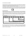
Serial Number Definition
Automatic Products int’l ltd. has introduced a new serial numbering method to permit better tracking of
machines, and any changes that occur. This information is being provided to you so that you understand the
information contained in the serial number, and so that when you are making an inquiry about a specific
machine, or require a warranty replacement, that you provide us with the complete serial number. The location
of the serial number plate in the machines has not changed. The serial number plates are located inside the
machine in the upper right hand corner of the cabinet, and adjacent to the power cord on the back of the
cabinet.
It is essential that the complete serial number be reported when reporting any problems or claiming any
warranty replacements.
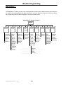
The new serial number format is explained in the example below:
4
2
2
0
Ï
2
3
Ï
6
5
0
0
1
Ï
Ï
Sequential build
number
Starts at 001 every day.
Numerical day of the year – Jan 1st = 001, Dec 31
= 365.
Year 02 – Last two digits of the year. 2002
First digits indicates model, example shown is a 223 (Export Hot Beverage Merchandiser – The
machine identification may contain up to six characters dependent upon the model.
All equipment manufactured by Automatic Products intl. ltd. is designed to work properly in a temperature range
of 10° C to +38° C (50° F to 100° F) in still air (75% R.H. non-condensing). The unit is capable of being of being
stored in a temperature range of -18° C to +68° C (0° F to 155° F). Provided proper precautions are taken for
machines that contain a water system to prevent physical damage to components due to freezing, and that the
machine is not stored in direct sunlight
Automatic Products
223 V3.0
2/2004
III
PART # 27500015
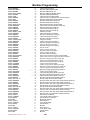
Table of Contents
Rack Configuration “C” (1-1-2 -3)..................... 405
Rack Configuration “D” (1-2-2-2)...................... 406
Rack Configuration “E” (1-1-1 -4) ..................... 407
Rack Configuration “F” (1-1-1-1 - 3) ................. 408
Rack Configuration “G” (1-1-1-1-1 -2) .............. 409
Rack Configuration “H” (1-1-1-2 -2).................. 410
Rack Configuration “F/FDX” (1-1-1-1-3-X4) ...... 411
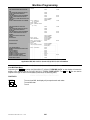
FEATURES / OPTIONS...................................... 100
Standard Features ........................................... 100
Options ............................................................. 100
Specification ..................................................... 100
Electrical Requirement ..................................... 100
Water Requirements ........................................ 100
Model and Capacities ....................................... 101
Cup Models & Capacities ................................. 101
Compatible Coin Mechs & Bill Validators ......... 101
MasterMenu Online™ Software ........................ 102
Personal Computer Requirements ................... 102
Touch Memory Button (TMU) ........................... 102
TMU Upload / Download .................................. 102
Hosting APi 127 Expander ............................... 100
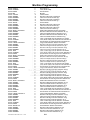
MACHINE PROGRAMMING
MIS (Management Information System).............. 500
Setup Menu ........................................................ 513
Bill Escrow Menu .......................................... 513
Free Vend Menu .......................................... 513
Winner Vend Menu ...................................... 513
Multiple Vends Menu .................................... 514
Force Vend Menu ....................................... 514
Set Max Payout Menu .................................. 514
Set Payout type ............................................ 515
Temperature Override Menu ........................ 515
Own Cup Discount ....................................... 515
Executive Vend Menu .................................. 515
Energy Shaver ............................................. 516
Configuration Menu Items Introduction
. ........ 517
Configuration Upload/Download Menu ......... 517
Water Set Temperatures Menu .................... 517
Set Function Keys Menu ............................. 518
Cup Substitution .......................................... 519
Printer Setup Menu ..................................... 519
Beverage Definition Menu ................................. 520
Recipe Definition Menu ................................ 520
Brewer Controls ........................................... 521
Setting Duration Times Menu ....................... 522
Name Creations Menu ................................. 524
Name Assignment Menu ............................. 525
Drink Size Definition Menu ........................... 526
Price Menu Items Introduction ............................ 600
Price Assignment Menu ............................... 600
Check Prices Menu Item .............................. 600
Diagnostic Menu Items Introduction ................... 601
View Errors Menu ......................................... 601
Clear Errors Menu ........................................ 601
Test Vend Menu ...........................................601
Motor Test Menu .......................................... 602
Brewer Test Menu ........................................ 602
Water Valve Test Menu ................................ 602
Whipper Test Menu ...................................... 603
Water Tank Check ....................................... 603
Auxiliary Functions Test Menu ...................... 603
UNPACKING / INSTALLING
Shipping Damage ............................................. 200
Location Site Requirements ............................. 200
Location Set-Up Instruction .............................. 200
COMPONENTS
Numbered Keypad System .............................. 300
MasterMenu Keypad ........................................ 300
Function Buttons .............................................. 300
Coin Payout Buttons ........................................ 301
Control Systems & Boards ............................... 301
Coffee Control Board (CCB) ............................. 301
Coffee Driver Board (CDB) ............................... 301
Front Scrolling Display ...................................... 302
Power Supply .................................................... 302
Lighting System................................................. 302
Cup Dispensing Assembly ................................ 302
Selection System ............................................. 302
Door Service Switch.......................................... 302
Automatic Vend Door ........................................ 302
Canister Rack Assembly ................................... 302
Water Tank ....................................................... 303
Brewer Unit ....................................................... 303
Cupwell Assembly............................................. 303
Cup Catch Assembly......................................... 304
Use Yur Own Cup Feature ................................ 304
Hopper Swing-Out Assembly ............................ 304
OPERATIONAL SET-UP.................................... 400
Configuration Layout ......................................... 400
Ingredient Product in Canisters ........................ 400
Selection Buttons .............................................. 400
Selection Log Table .......................................... 401
Gram Throw Instructions ................................... 402
Cup Cabinets .................................................... 403
Set Prices.......................................................... 403
Cup Level Adjustment ....................................... 403
Rack Configuration Drawings
Rack Configuration “B” (1-2 -4) ........................ 404
Automatic Products
223 V3.0
2/2004
SERVICE INDEX . .........................................….700
...........................................................................................................................
IV
PART # 27500015
The Automatic Products int'l 223 Hot Beverage Merchandiser contains the state of the art in vending
technology. The APi 223 is equipped with MasterVend™ Control System and the MasterMenu™ System. The
MasterMenu™ System provides a text based user-friendly menu system that is used to set-up and configure
the APi 223 Hot Beverage Machine. The simple operation and built-in flexibility of this system allows each user
to customize the menu system to their preference. The system can be configured to display service and
operational mode messages in any of eight different languages and support a variety of drink "recipes" and
ingredient selections. Robust testing capability as well as extensive diagnostics and error reporting facilities are
built into the APi 223 to provide ease of maintenance. The APi 223 includes a fully configurable front panel and
internal inventory assignment, random free vend, four (4) levels of security, a real time clock, a variety of
discount and pricing options, storage/retrieval of MIS information, and the Quick Select vending feature.
HOW TO USE THIS MANUAL
This manual is divided into five sections:
SECTION TOPIC
100
Features / Options
200
Unpacking / Installation
300
Components
400
Operational Set-Up
500
Machine Programming
600
Service / Troubleshooting
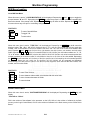
WATCH THROUGHOUT THE MANUAL FOR THIS
SPECIAL “ X “ DIAMOND MARK. THIS INDICATES
A POINT OF SPECIAL INFORMATION OR HINT
THAT WILL ASSIST YOU IN SETTING UP,
OPERATIONG, OR TROUBLESHOOTING THE
MACHINE
CCAUTION: Certain procedures in both the operating section and the service section
require that voltage be on in the machine. Only trained personnel should perform this
function. Exercise extreme caution while performing these procedures. These procedures
will be marked with the lightening bolt symbol as it appears at left.
CCAUTION: Certain procedures in both the operating section and the service section
requires a qualified trained technician to perform the particular task at hand. These
procedures will be marked with the exclamation symbol as it appears at left.
CNOTE: The APi 223 machine operates at a level of less than 75dba.
Automatic Products
223 V3.0
2/2004
V
PART # 27500015
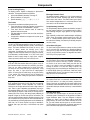
Features / Options
STANDARD FEATURES
•
15 or 10 Beverage Selections
•
Up to four coffees, multiple blended drinks, soluble
gourmet beverages, soup, tea, cocoas, and
compliments.
•
Consumer Friendly selection system utilizing
tactile feel buttons and flashing buttons.
•
Three programmable beverage strengths.
•
Universal Swing-Out Hopper Assembly
•
USE YOUR OWN CUP option with or without
discount feature.
•
Dual Adjustable Cup Dispensers.
•
Brewer Assembly with programmable five speed
motor & function delays
•
Multi Drop Bus capabilities.
•
Extensive Diagnostics capabilities.
•
Friendly Text Based Interface.
•
Configuration Upload and Download capabilities.
•
User Programmable function keys.
•
Cupwell Assembly: illuminating lamp, cup sensors,
motorized two position spout and automatic vend
door.
•
MasterMenu ready
•
Programmable Automatic Cleaning cycles
•
Point of Sale window (Odyssey style)
•
“Quick Select” numeric key pad with Braille buttons
•
Four Program Security Levels.
•
Six Programmable Languages.
•
Machine Reset capability.
•
Real Time Clock.
•
Personal Computer Interface.
•
Printer Interface.
•
Chime
•
Price line Accountability
•
Global Pricing by Machine
•
Pricing by Selection and Size
•
Extensive Discounting capabilities.
•
Shutdown capabilities.
•
Programmable Winner Mode available as
standard.
•
Free Vend Feature.
•
Forced Vend and Bill Escrow features.
•
Upload and Download capabilities for Pricing and
MIS.
•
Programmable maximum payout.
•
Extensive Accountability, including all Discounts
and SCROLLING DISPLAY
•
User-friendly scrolling display to help with the
selection process and provide customer feedback.
•
User programmable point of sale and operational
messages.
•
20 Character Display.
•
Stores three different Point of Sale Messages.
•
User Settable After Sale and Out of Order
messages Free Vends.
Automatic Products
223 V3.0
2/2004
OPTIONS
•
10 Selection Button Panel
•
Non-Back lit “C” Graphics
•
Five Canister Rack Configurations
•
Swing-Out Hoppers-from 1 to 3 compartments
with varies Loose ground and grinder
configurations
•
Whipped Soluble Gourmet Coffee (SGC).
•
Point of Sale Window (traditional style)
•
MasterMenu Online Software hardware package.
•
Rinse Drip Tray
•
Kick Plate Asm.
•
Transportable Memory Unit (TMU).
•
All soluble machine with up to eleven canisters
SPECIFICATIONS
•
Height – 72” (183cm)
•
Width – 38” (97cm)
•
Depth – 31” (78cm)
•
Floor space required – 9.5 SQ. FT
•
Shipping container size – 72.5 CU. FT.
•
Shipping Weight (approximate):
All Soluble Unit = 460 lbs (209kg)
Loose Ground = 500 lbs (227kg)
Bean Grinder = 560 lbs (254kg)
ELECTRICAL REQUIREMENTS
Electrical: 120 VAC (+/-10) ; 60 Hz
20 Amp Dedicated Line
Maximum Operating Amperes – 16 amps
WATER REQUIREMENTS
•
Potable Drinking Water
•
Cold Tap Water
•
20 PSI minimum
•
Minimum 3/8” O.D. water line recommended to
machine.
•
Manual shutoff within six feet of the machine
100
PART # 27500015
Features / Options
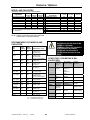
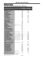
MODEL AND CAPACITIES
Ingredients measured in pounds unless specified.
1/3
2/3
3/3
Ingredients
Hopper Hopper Hopper
Loose Ground Coffee
6 lbs
12 lbs
18 lbs
Loose Ground Decaf
6 lbs
12 lbs
18 lbs
Loose Ground Dark
6 lbs
12 lbs
18 lbs
Fresh Bean Coffee
6 lbs
12 lbs
18 lbs
Fresh Bean Decaf
6 lbs
12 lbs
18 lbs
Fresh Bean Dark
6 lbs
12 lbs
18 lbs
Note: above weights are approximate and can vary by
(+/-) 1/2 pound
1 Level
2 Level
Ingredients
Soluble 'FD' Coffee
1.5
3.0
Soluble 'FD' Decaf
1.5
3.0
Soluble ‘FD’ Tea
1.5
3.0
Sugar
4.0
8.0
Sugar Substitute
10 oz
-Whitener
2.0
4.0
Chocolate
3.0
6.0
SGC
2.5
5.0
Soup
2.0
4.0
Note: above numbers are in ounces
3 Level
-----6.0
9.0
7.5
6.0
Canisters may be expanded
Level = number of canister levels that includes the
bottom base + extension sections.
NOTE: IN MACHINE, THE
PERIFERIALS BELOW SHOULD BE
PAIRED TO THE SAME
COMMUNICATION TYPE. EXAMPLE;
MDB COIN MECH WITH MDB
VALIDATOR. PULSE 24 VOLTS
VALIDATER WITH 24VOLTS COIN
MECH.
RECOMMENDED CUP MODELS AND
CAPACITIES:
Cup
Size
Large
Cabinet
Small
Cabinet
7 oz.
656
429
(Swt♥) PV577,
(IP) SVR-0070
8¼ oz.
590
378
(Swt♥) PV588,
(IP) SVR-0080
Conf Cup 210-2000AV
Manufacturer Cup #
8 oz. insul
262
170
(Swt♥) V8X
COMPATIBLE COIN MECHS & BILL
VALIDATORS:
9 oz.
552
356
10 oz.
543
354
(Swt♥) PV509,
(IP) SVS-9
(IP) SVR-10
(IP) SMR-10
12 oz. tall
533
341
(IP) SVR-0120A
12 oz. squat
552
352
(IP) SVS-0120
(Swt♥) PV512T
Conf Cup 355-2000AV
12 oz. squat
334
228
(ICC) HM1200
12 oz. squat
549
366
(Sw♥t) PV512
12 oz insul
tall-squat
240
158
(Swt♥) V12TX
12 oz. insul
321
203
14 oz.
14 oz.
Cup Brand Indicators:
Automatic Products
Coin Mech
Micro 24V
15 Pin
Bill Validator
Pulse 24 Volts
Validator
Harness #
MARS
TRC6010XV
680637 (APi)
COINCO
9302 LF
USD-L701
USLX-00101F
VN2502-U5E
VFM1-L2U4C
VFM3-L2U4C
BA32SA
BA32R
CONLUX
MARS
(Swt♥) V12X
COINCO
(IP) SRV-14
CONLUX
(ICC) HV1400
Swt ♥= Sweetheart Cup
IP = International Paper Co.
ICC = International Cup Corp.
223 V3.0
2/2004
101
680637 (APi)
680637 (APi)
MDB Coin
Mechanism
TRC-6510
TRC-6512
VN-4510
9302-GX
USD-L701
MDB Bill
Validator
VN2502-U5M
USLZ-00401F
USLZ-00401F
Validator
Harness
26800008 (APi)
BA32A**
BA32R
26800008 (APi)
26800008 (APi)
PART # 27500015
Features / Options
MASTERMENU ONLINE (MMOL) SOFTWARE
Kit # 17500005
(MMOL) software gives you the capability of completely
setting up any 223/423 Hot Beverage Merchandiser, 120
Series snack Merchandiser, 310 Control Module, or 320 Food
Merchandiser machine on your personal computer (PC).
(MMOL) also has the ability to load complete new logic board
software revisions to a machine. To load complete new
software into a machine the PC must be connected directly to
the machine logic board via a cable P/N 56800022 and the
DEX/UCS harness P/N 680509. These updates can be sent to
you via e-mail or as a file on a floppy disk.
Personal Computer Minimum Requirements:
To install the MMOL Program you need:
•
•
•
•
•
•
•
•
Personal or Multimedia computer with 486 or higher
processor
Microsoft Windows 95 operating system or later. (NT not
compatible)
16 MB of RAM with Windows 95. Newer Widow systems
requires more memory.
20MB of hard disk space required.
VGA or higher resolution video adapter.
Microsoft Mouse or compatible pointing device.
RS232 -9 pin Com connection or USB to serial adapter.
3.5 inch floppy drive.
Touch Memory Button P/N 17500003
The Touch Memory Button (also called CHIP) can be used to
download or upload from any APi 120 / 320 / 223 Series
Automatic Products
223 V3.0
2/2004
Machine. CHIP is capable of storing all settable data from a
machine, with the exception of the time and date. Once CHIP
is programmed; you can take it to as many machines as you
wish to upload the information stored in CHIP. CHIP can be
overwritten and reused as many times as desired. Chip is
mounted on a key chain holder. CHIP can be programmed
from a machine that is already set up and then used to set up
other machines that are to be programmed identically. CHIP
can also be programmed from (MMOL). (MMOL) is a
software program that allows you to set up any of these
machine on your personal computer (PC). This information
can then be stored by filename in your PC and is always
accessible for any changes you may want to make the
machine in the future, including pricing. To load CHIP from
your PC requires harness P/N 17500004, included in this
package.
TOUCH MEMORY BUTTON (CHIP) AND
UPLOAD/DOWNLOAD HARNESS P/N 16800013
The CHIP upload/download harness is attached to the Logic
Board (CCB) on J1 (upper right hand corner) and the other
end is mounted on the selector panel flange just below the
free vend switch. Six of these harnesses included in the
package.
Hosting APi 127 Expander
The Café Diem can host and operate a Model 127 add on
snack/pastry machine. (must order harness # 26800068).
102
PART # 27500015
Unpacking / Installation
The APi 223 is assembled and packed so that a minimum amount
of time is necessary for preparation to install it on location. The
following steps are recommended to insure correct unpacking.
1. SHIPPING DAMAGE: Thoroughly inspect the exterior of the
carton for damage, which may have occurred during
shipment. If damage is present, remove shipping carton and
plastic bag from vendor. Inspect exterior and interior of
cabinet for damage. Report any damage to delivering carrier
and follow their instructions.
2. Remove clip from lock handle and open front door. If machine
is equipped with a lock, the keys will be in the cupwell.
Inspect cabinet interior for evidence of damage.
3. Remove cardboard canister rack insert and all packing tape
from coffee hopper swing out bracket, cup dispenser door,
commodity trough and steam deflector, overflow and grounds
waste bucket floats.
Warranty: The warranty card is attached to the cover of this
manual. It must be filled out in full and mailed at once to insure
coverage.
1. Remove all cartons from floor of machine. These
Cartons may contain the kick plate, grinder swing out bracket,
coffee or bean hoppers.
Location Site Requirements
This vendor requires an external source of water and electricity
for operation. The minimum requirements for these utilities are as
follows:
IMPORTANT!
A dedicated grounded electrical outlet rated at 120 volts, 60Hz,
single phase and capable of delivering 20 amperes must be
available within six feet of the vendor. Only a receptacle that
contains a right angle neutral should be used and the Hot
Beverage Merchandiser should be the only unit connected to this
outlet.
Voltage and Polarity Check
It is important that this machine is hooked up to proper voltage
and polarity. Using a voltmeter, perform the following checks
from the illustration below.
Operating Environment
This machine is designed to operate properly in a temperature
range between 40F to 104F degrees in still air (75% R.H. oncondensing). This Unit is capable of being stored in a dry area
within temperature range of 10F to 155F degrees.
At temperatures below freezing, the water tank and water lines
must be drained from machine in order to prevent damage due to
freezing. The machine should not be stored in direct sunlight
Location Set-Up Instructions
CAUTION: THIS MACHINE IS DESIGNED FOR
INDOOR USAGE ONLY. ANY OTHER USAGE MAY
VOID THE MANUFACTURERS WARRANTY
Water
The installation site must have a cold drinking water supply line
that can be permanently coupled to the vendor. The water supply
line should be 3/8 inch minimum diameter and be equipped with
a manual shutoff within six feet of the machine. Water
pressure should maintain 20 PSI minimum while the vendor is
taking onwater. If water pressure exceeds 90 PSI, a pressure
regulator should be installed in the line. The standard plumbing
connection shipped with the machine is a " male flare fitting.
ENSURE THAT THE WATER SHUT OFF LEVER THAT'S
ON THE INLET WATER FILTER HEAD ASM IN THE MACHINE
IS CLOSED BEFORE HOOK UP OF WATER SUPPLY (TURN
LEVER CCW).
Electricity
CAUTION: THE FOLLOWING
PROCEDURE REQUIRES THAT THE
MACHINE HAVE POWER APPLIED
AND A POTENTIAL ELECTRICAL
SHOCK HAZARD EXISTS
Automatic Products
223 V3.0
2/2004
115 VAC
(+15/-10)
Between
Hot to
Neutral or
Ground
1 Volt AC
Maximum
Between
Neutral
& Ground
CAUTION: THE FOLLOWING
PROCEDURE REQUIRES THAT THE
MACHINE HAVE POWER APPLIED
AND A POTENTIAL ELECTRICAL
SHOCK HAZARD EXISTS
Set up the vendor at the location as follows:
1. On the power switch panel, located on right side wall, upper
corner of cabinet, set all switches to the OFF positions.
2. Leveling the Machine: This step is very important for the
proper function of machine. The four leveling screws in the
legs are the means of leveling the machine. After positioning
the machine, level machine in front to rear and right to left
directions. After leveling, turn front right (lock side) leveling
screw in about one-half turn to drop this corner slightly to
make the door easier to close and lock.
3. If machine is not equipped with a large bean grinder, swing
the coffee hopper out and install hopper. Be sure to engage
auger driver with motor drive pin.
4. If machine is equipped with a bean grinder, swing out
bracket assembly and hopper will be packed separately and
placed on the floor of the machine. Install the grinder swing
out asm on the hinge bracket and connect the electrical
harness. Be sure to secure the sliding gate (located on the
sloped surface of the bean hopper) in the fully open position
to allow beans into the grinder(s). Push the swing out asm
against brewer and verify that the spring lever latches itself.
200
PART # 27500015
Unpacking / Installation
5.
6.
7.
X
8.
9.
Install water filter cartridge (if so equipped) onto the filter
head asm. Open the water line by turning the lever on the
filter head fully clockwise.
Remove all shipping screws and bottom shipping bracket
from cup dispenser assemblies.
Connect the vendor to the water supply line using 3/8" O.D
compression fitting. We recommend using soft copper
tubing. The tubing should be coiled one complete circle
approximately three feet in diameter between the water
supply line and vendor to allow movement of the vendor for
cleaning and to reduce noise due to water pressure surges.
ENSURE THE VENDOR MAINTAINS A SIX- INCH
DISTANCE FROM BEHIND WALL. THIS IS NECESSARY
FOR VENTALATION.
Plug the machine into a 120 volts 60Hz, 20
Amps DEDICATED receptacle. Set all power
switches to the ON position. Check that the tank starts to fill
and that there are no leaks. The cup spiral motor will run for
thirty seconds and time out or if cups are installed, until the
cup present switches are depressed.
The machine will energize the water Inlet Valve to allow
water into the tank. The machine is equipped with a 90
second safety feature - that if the inlet water valve is on for
more than 90 seconds, it will put the machine out of order
with a display message of "WATER LEVEL LOW". To
complete the filling process, power the machine OFF/ON to
Automatic Products
223 V3.0
2/2004
10.
11.
12.
13.
14.
15.
♦
201
reset the 90-second timer. It may be necessary to reset the
90-second timer twice in order to fill the tank completely.
Remove all packing material.
Loosen the two screws holding the brewer grounds
splashguard on the front of brewer. The shield is designed
to be able to swing a little as the spent grounds fall against
it.
Place plastic bag liner into grounds bucket. Install grounds
bucket behind front flange of rear splashguard. Be sure that
the float is inside the bucket.
Install overflow bucket under the cupwell assembly and
position against and between guides. Be sure that the float
and overflow hose are hanging over the bucket.
Open cup dispenser doors and load with cups. Cup
dispensers are factory set to cup sizes specified during
ordering process. If other cup size is desired, refer to
service section for Cup Dispenser Adjustments. Also in the
program you will need to reset Drink Size under the
“Beverage Definition” Menu.
Install coin mechanism and bill Validator and connect to
applicable harnesses. See decal on Coin Mechanism
enclosure for list of acceptable coin mechanisms.
223 HBM. SUPPORTS THE EXECUTIVE AND
MDB PROTOCOLS FOR COIN MECHS,
VALIDATORS, AND CARD READERS.
PART # 27500015
Components
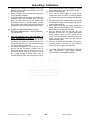
Number-Keypad System
The keypad system used with the MasterVend™ Control System
is different from all previous alphanumeric systems we have
manufactured. The eleven digit selection panel (see Figure 2.1)
is located on the front control bezel and consists of the numbers
0 through 9 and the letter C, which is defined as a clear button.
The selection system used with the MasterVend™ Control
System consists of a 15 or 10 selection panel and a numeric
keypad to identify all the selections.
MasterMenu™ Keypad
The MasterMenu™ keypad (see below) is located on the front of
the machine directly to the right of the main selection keypad.
The MasterMenu™ keypad is only active when the main door is
open and the interlock switch is actuated, so even in the event of
vandalism to the control bezel, no access to the control functions
is permitted. The MasterMenu™ keypad consists of seven
function buttons, a key, four coin payout buttons and the eight
keys used to operate the MasterMenu™ functions. The entire
keypad becomes active once the machine door is opened.
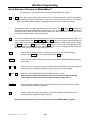
Function Buttons
The seven MasterMenu™ function keys (F1-F7) are assigned to
specific pre-determined functions, primarily for route service
personnel. The MasterMenu™ function keys are also assigned to
specific functions while in Beverage Definition / Recipe Definition
to build a drink.
Pressing the key along with one of the function keys F1
through F7 are specific to the second level of menu heading /
items currently active. The key can also be used for
wildcarding in the pricing of all selections for the particular cup
size.
The Quick Select Keypad allows items to be selected when the
machine is in Operational Mode. A Four (4) digit code can be
entered via the Quick Select Key Pad rather than using the
normal selection process. The Four (4) digit code will correspond
to a unique drink in the machine. The numeric keys on the
selector panel can also be used to enter numeric data any time it
is required during setup or maintenance of the equipment.
F1
F2
.05
F3
F4
.10
ESC
F5
F6
.25
INS
1.00
DEL
F7
Automatic Products
NOTE: Upon Depressing the ENTER button, the
MasterMenu System will then be in the enhanced
program mode. At this point the ‘F’ button keys
will not function. To reuse the ‘F’ buttons you will
need to reinitialize the machine by depressing the
door Service Switch.
223 V3.0
w
2/2004
+
400
ENTER
PART # 27500015
Components
Coin Payout Buttons
The four coin payout buttons are used to pay coins out of a MDB
or 24 Volt compatible US Coin Mech. The four coin payout
buttons are .05 , .10 , .25 , and 1.00. The four coin payout
buttons may also be used to enter pricing information while
assigning prices. For example, to enter a price of $.65, pressing
the .25 key twice, the .10 Key once and the .05 key once,
would result in .65 appearing on the display. See the Price
Setting section for additional information.
The ESC key is used for exiting the current menu without
making any changes prior to commitment. Note: Closing the main
cabinet door will have the same effect as if the user depressed
the ESC key and causes the machine to exit the MasterMenu™
System and return to Operational Mode.
The ENTER key provides a dual-purpose operation. It provides a
mechanism for choosing a menu heading. It also provides a
means to commit insertions / modifications / deletions made in a
menu item.
Note: Depressing a function key will not cause
you to enter the MasterMenu™ System.
The + and – keys provided are used for increasing and
decreasing the available choices in a menu.
Note: Anywhere in this manual that the + and –
keys are defined to sequence through numeric
data, the front panel may be used as an alternate
input source.
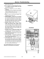
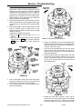
Coffee Control Board (CCB)
The CCB controls the overall operation of the machine. It
interfaces with the Coffee Driver Board, Display Board, Selector
Panel, MasterMenu keypad, Coin Mech, Bill Validator and all
other peripherals. The CCB also stores all the programming and
MIS information. This circuit board is universal for all 20 series
machines that includes the Models 120 Snack/Candy, 320 Food,
and Café Diem Hot Beverage Machine. The board is mounted in
a box attached to the right side of the Coin Mech housing box
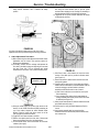
Coffee Driver Board (CDB)
This circuit board is located on ceiling of the cabinet. It monitors
and supplies power to all 24DC volt devices. It has it’s own
microprocessor that controls and monitors many of the machine
functions.
The Coffee Driver Board contains all the inputs and outputs
controlling all functions for machine motors, water valves, and
pumps. The Coffee Driver Board communicates with the CCB via
a 6 wire computer level interconnect harness called the MDB
harness. The front of the CDB contains eight LED’s and three
momentary switches that are labeled. The status of the CDB can
be determined by observing the LED’s when the machine is in an
operational standby condition:
Ο - LED is off during standby
n - LED is on during standby
}
- LED is blinking in standby
Ο/n - LED can be Off or On during standby
Chiller
comp.
Tank
level
low
Tank
heater
on
Cups
needed
Spout
home
Cupwell
no
obstacle
Ο
Ο
Ο/n
Ο
n
n
The < and > keys have a dual-purpose operation. They provide
a means to select the menu heading immediately to the left or
right of the current menu heading. When inserting data within a
menu, these keys also provide a means to move the cursor from
its current position to the position directly to its left or right.
Chiller Compressor
Tank level low
The DEL key is used to delete the character on the current
cursor position, shifting all subsequent characters to the right of
that position left by one.
Cups needed
The INS key provides a mechanism to insert a character to the
left of the current cursor position, shifting all characters to the
right of that position (including the current character) right by one.
Or, down when inserting Recipe steps.
CONTROL SYSTEM AND BOARDS
The MasterVend™ Control System consists of up to three
different boards, depending on the configuration. All 223 Models
consist of the Logic control board (CCB) and the Coffee Driver
Board (CDB). When a machine is equipped with a grinder unit
the machine will have a third board. The third board is the
Grinder Driver Board (GDB) located along the rear right wall of
the cabinet.
Automatic Products
223 V3.0
2/2004
Tank Heater on
Spout home
Cupwell no obstacle
Motor Power Ready
MDB Status Heartbeat
Motor MDB Status
power Heartbeat
ready
}
This LED should not be lit (Ο).
The LED is on (n) only when the
tank water level is low
The LED is on (n) only when the
heater is on. (on steadily means
heater is on)
The LED flashes once (}) when
dispenser 1 is out or 2 flashes when
dispenser 2 is out of cups.
The LED is on (n) steadily in standby.
The LED is steadily on (n) until a
cup is placed into cupwell.
Flashing off/on (}) in standby.
Flashing off/on (}) in standby.
The three momentary switches serve as service test switches for
the coffee and tea brewers. The push button switches are located
to the right of the LED status indicator lights on the CDB.
The board is easily accessible by loosening the two outer thumb
screws and tilting the board down from the panels hinges.
401
PART # 27500015
}
Components
Front Scrolling Display
The display board is capable of displaying 20 alpha-numeric
characters. The supported character set includes:
• Upper case alphabetic characters "A" through "Z"
• Numeric characters "0" through "9"
• Special characters: (, ), [, ], ., ', -, =, $, /, \, *, ^, +,", ?,
The Chime
The chime will sound when the following events occur:
• Three times when an invalid key sequence is entered from
either the front panel or the MasterMenu™ Keypad.
• Three times when the customer enters an invalid key
sequence from the front panel.
• Five times when the customer has won a free vend due to
WINNER MODE.
• A single time to indicate the acceptance of an action by the
control system.
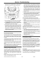
Power Supply
The APi 223 Hot Beverage Machine utilizes the incoming 115
VAC to power the heating elements, grinders, and fluorescent
lamps. The Power Distribution Box located at rear top right
corner of cabinet, houses the following power supply
components: A transformer that converts the input 115 VAC
voltage to 24 VAC and 8 VAC used by the Coffee Control Board,
Coin Mechanism, and Bill Validator. A 24 VDC Power Supply
Module is used to supply voltage to auger motors, whippers,
valves, spout motor, brewer motor, and vend door motor.
Lighting System
In the APi Café Diem machine with back-lit graphics, there are
four fluorescent lamps in the main door powered by one ballast.
There are two lamps located in the top section of the door,
one along the left vertical side, and one in the bottom. These
lamps are used to light up the front “C” shape graphic
section. A Service light is located along the top front section
of the cabinet. The service light will come on whenever the
main door is opened causing the light switch to activate the
lamp circuit.
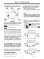
Cup Dispenser Asm.
Every beverage sold through the 223 Cafe Diem hot beverage
merchandiser requires a clean disposable cup. Inside the
machine are two storage cabinets that house a large number of
cups. There is a pair of adjustable cup separators (cup ring) to
accommodate different size cups. The adjustable cup ring has
been designed to dispense a wide variety of vending and nonvending cups. Each cup ring, after being properly adjusted, will
dispense a single cup for each vend cycle of the machine. The
cups are stored in between spiral that will index the stack of cups
over to replenish the cup ring when low. Both cup dispensers are
fully convertible by performing adjustments to accommodate cup
sizes from 6 to 14 ounces. Special cup rings are available to
dispense foam cups (red cams) or thick-rimmed cups (black
cams).
Automatic Products
223 V3.0
2/2004
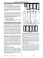
SELECTION SYSTEM
Beverage Selector Panel
The selection system is available in a 10 or 15 button panel that
utilizes tactile feel buttons. Beverage type labels are inserted
behind these clear buttons. The plastic buttons push against
micro switches located behind on a circuit board. Next to each
micro switch is an LED to indicate when selected.
Complimentary Switches
The Complimentary Selection Switches are located to the right of
the main selection switches. The complement board is used to
select beverage strengths, sugar, lightener, & sugar substitute
(optional).
Each commodity contains three variable strengths and flashing
LED’s. During the customer selection process, the LED’s will
flash to indicate available options. When customer chooses
the button that is flashing, it will then stay lit indicating this option
has been chosen.
Quick-Select Keypad
The Quick-Select Keypad allows the customer to select a coffee
item for purchase when the machine is in Operational Mode by
entering a four (4) digit code via the numeric keypad rather than
using the normal selection process. The keypad is also used to
enter settings in the program mode.
Door Service Switch
The Door Service Switch allows the MasterMenu Keypad to
become ACTIVE when the front door is opened. This also puts
the machine in the service mode. Closing the main door will
press in the interlock switch and reinitialize the machine by
scanning for devices to be home and ready to operate. The
following devices are checked during the initialization scan: cups
in the Cup Rings, Spout up & down home, Vend Door closed,
and Brewer Motor homed. This switch is located on main door
edge next to the coin mechanism box
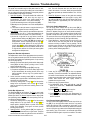
Automatic Vend Door
The Cupwell Vend Door is an automatic motorized door. The
doors main function is for safety and sanitary requirements.
During a vend cycle, the cupwell door will remain closed and the
cupwell lamp will be illuminated. At the end of the vend cycle, the
cupwell door shall open and wait until the cup is removed before
closing.
Canister Rack Asm.
The canister rack provides support for the entire dry product
commodity system. Containers for the dry product are made of
rugged translucent plastic. They are designed to dispense
products on a first-in / first- out basis in order to insure fresh
product delivery. All motors on the canister assembly are 24 Volt
DC. The main canister rack will support up to seven canisters.
On FDX models that vend all soluble, an extension rack takes the
place of the brewer that support four additional canisters.
402
PART # 27500015
Components
The assembly consists of the following;
A) Auger Motors that drive the canister spirals to dispense
product. There are two different auger motors depending on
speed of 180 and 51 RPM’s.
B) Canisters – There are several different assemblies
depending upon capacity and product type. The canister
capacity comprises of a base and maximum of three
extensions high. The product type (i.e. Sugar, SGC, FD Tea,
etc.) will determine what type canister is used with one of the
following
C) Components: agitating wheel, spiral coil, spout, and leaf
spring agitator. The auguring system used to dispense the
products runs in reinforced nylon bearings to ensure a long
trouble-free life. The dispensing ends of the canister are
direct flow spouts, some of which have louvers. These
louvers help control sifting of product due to vibration. On the
front side of the canisters, there are levels markings so that
the service person can easily refill them to a pre-determined
level. This type of control will reduce product waste and
assure commodity freshness by the elimination overfilling.
D) Mixing Bowls and Toughs are used to mix the powdered
product with hot water. The troughs allow powdered product
from two to four canisters to dispense into the same channel
to mix with flow of water. This process is only used with
products that do not cross contaminate with taste and rinse
properly.
E) Whippers used to whip, mix and create froth on finished
drink.
F) Exhaust System is used to help remove steam vapors from
the hot water that flows into the bowls and troughs are
controlled by this system. The steam vapors are exhausted
behind the mixing bowls and trough before it raises into the
cover chute and canister spouts. This prevents powdered
product from sticking to surfaces and clogging. Uncontrolled
steam in a vending machine will create severe problems
through caking and hardening of the dry products. Such a
condition will prevent proper dispensing. By moving low
velocity air, in a high volume through area where steam is
generated. The canister rack exhaust system consists of
bowl covers, trough chute, exhaust box, two plastic exhaust
hoses, exhaust fan asm (24VDC), and filter screen.
Water Tank
The water tank design is the latest in technology in providing a
very high volume output at a stable temperature range to
accommodate customer demand. The entire Tank assembly is
designed to tilt down for ease of serviceability to access lid
components. The water system in the tank is a gravity system
thus requiring no pumps or compressors. There is an open-air
break (1 1/2” minimum) between the tank inlet and water level for
the prevention of water back flow, which is required by most local
codes. There are two temperature control probes that maintain
the water temperature at a settable point. It is recommended that
the water temperature is set between 190F to 202F degrees for
proper extraction of fresh brewed coffee (factory setting = 200F).
The Water Tank is located on the back wall of the cabinet. The
Water Tank is fitted with five commodity water valves and one
brew water valve, two heating elements, two water / temperature
probes, a rinse hose, and drain hose.
Automatic Products
223 V3.0
2/2004
Brewer Unit
The heart of the APi 223 Hot Drink Merchandiser is the open
cylinder brewer. It has been "time proven" and "experience
improved". It is simple, lightweight, easy to clean and service.
The brewer is capably of brewing from 6 to a 14 once cup (over
12 ounce requires add hot water). The basic function of this type
Brewer is to push hot compressed water through the coffee
ground then push compressed hot air through the coffee grounds
in order to remove the excess moisture. The Brewer Unit is
mounted to the upper right side of the back wall in cabinet. The
brewer unit consists of a 24VDC motor with an optical positioning
encoder and one cycle homing cam and switch. It is mounted on
a hinge bracket so it could be swung out for service or easy
removal. A latching pin on the right side of the brewer assembly
allows swing-out function.
Cupwell Asm.
Used to stage and position a cup in order to receive liquid
dispensing from spout The Cupwell Assembly consists of a
molded housing, spring loaded cup catch arms, removalable grill
and drain pan, spout assembly, metal cup chutes, and cup
sensors. The housing is made of a black molded plastic that is
mounting in the machine cabinet and remains stationary. The
Cup Catch Arms swivel open to help position the cup directly
under the dispensing spout. The grill and drain pan funnel liquid
into the waste bucket. They both pull straight out for thoroughly
cleaning. The spout assembly mechanically moves to the upper
or lower position depending on the height of a cup. This helps
prevent splatter from dispensing liquid into cup. The spouts other
function is to stage a cup before it drops into the cup catch arms.
This is performed by stopping the cup against the spout while in
the down position then the spout raises and the cup drops into
the cup catch arms at controlled speed. The left and right cup
chutes are made of a heavy gauge stainless steel. The left chute
is used for cups dropping from low capacity cup magazine and
right for high capacity cup magazine. The cup sensors boards
are located on the right and left outer side of the Cupwell housing
mold. These boards are the same and have a transmitter and
receiver sensor on each board. The boards are mounted 180
degrees across from each other to align the receiver with the
transmitter. The lower sensors are designated as the cup present
sensors. They are used to signal the control board that a cup
is present and to start the vend cycle. If a cup is not present,
the vend cycle will not continue and the display will show
“Try Again” or return credit. The upper sensors are used to
determine whether the spout should vend in the lower or
upper position depending on cup height.
403
PART # 27500015
Components
Power Distribution Box (PDB)
The PDB is located in the cabinet at the upper right top corner of
machine and extends along the right side wall top corner. The
PDB supplies power for components in the machine. Voltages
supplied are 120VAC via the line cord, 24 VAC and 8 VAC via
the Transformer. The PDB also consists of the following:
Power
Switches, Line Filter, 24 VDC Power Supply Module, Three
Relays (1 power and 2 heater), and Power Ready Board used to
switch on the 24VDC.
Cup Catch Asm.
The two-cup catches are located in the cupwell assembly. Their
main propose is to catch the cup sliding out of the cup chutes,
prevent it from tipping, and to center under the spout nozzles
ensuring proper alignment for liquid dispensing.
USE YOUR OWN CUP FEATURE
Customers may use their own cup by placing it into the cupwell.
This is performed by A) sliding open the vend door (mechanical
spout will move up), B) placing own cup onto center of grill in
between cup catches, C) inserting credit, D) selecting beverage
and pressing cup size. The bottom cup sensors will detect a cup
already in the cupwell and disable the machines cup dispenser. If
the cup inserted is a tall type, the upper sensors would detect this
and keep the spout in the up position during the vend cycle. If the
cup inserted is below the upper sensors, the spout will move
back down during the vend cycle. The Use Your Own Cup
Feature can also work in conjunction with the Discount feature if
desired.
Hopper Swing-Out Asm.
Used to house Fresh Ground beans or Loose Ground coffee.
This assembly functions in conjunction with a coffee brewer
assembly. The coffee hopper is a universal container that can be
configured from one to three compartments. This allows the
ability to operate from one to three types of coffees; Regular,
Decaf, and Gourmet (Dark) coffee. The hopper has two
removable divider walls and output inserts to achieve convertible
configurations using either beans or loose ground coffees.
Automatic Products
223 V3.0
2/2004
404
PART # 27500015
Operational Set-Up
The Operational Set-Up section will instruct the installer how to quickly setup your machine to operate using
configured factory settings. If you deviate from the configured factory settings, use the Machine Programming
section starting on page 500 for additional instructions.
Rack Configuration Layout
Determine which canister rack layout is the factory set-up for
your machine by viewing the configuration rack samples
displayed on pages 404 through 411.
Placing Product into Canisters
Upon determining which canister rack layout you have. Place the
flavored powdered products into each canister as described by
the drawing for your canister rack setup. On all rack
configurations, chocolate is always located on the far-left side
and considered Auger #1. The next following auger motor to the
right would be auger #2 and etc. When placing product into the
canisters; lift the lid on the canister. Open the product bag and
carefully pour product into the canister. When all desired levels of
products have been reached wipe down exterior canister area.
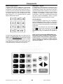
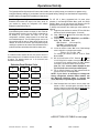
Selection Button Labels
A 15 Selection button machine will have three vertical columns of
selection buttons and a 10 Selection machine will have two columns
of buttons. The selection buttons are in the numbered order
described in below drawing.
Selection Panel Button Order
#1
#6
#11
#2
#7
#12
#3
#8
#13
#4
#9
#14
#5
#10
#15
The APi 223 is factory programmed with 30 preset recipe
selections. In the Beverage Definition Menu, under the “Recipe
Definition” Menu, you can scan through all 30 Recipes to find the
beverage flavor that is assigned to above selection buttons.
To identify which selection flavor labels goes where perform the
following
1. Toggle the power switches in machine OFF then ON. Allow
machine to scan & reinitialize (approx. 15 seconds).
2. Press & Hold In the + button and at the same time press
the F3 button.
3. If displays shows; “RECIPE DIFINITION” press ENTER to
display “R01 FG Coffee Sxx”.
R01 = Recipe #1
(R01 through R31)
FG Coffee = the beverage name
Sxx = assigned selection number
4. Look at the selection number “Sxx” to see if that beverage
name is assigned to a selection button number.
Example: “R01 FG Coffee S01”
This indicates that selection button #1 is set for “Fresh
Ground Coffee”.
5. With the courser flasher on “R01”, Press the + or - button
to scroll through all 30 recipes to view which beverage name
is assigned to which selection button. The “Sxx” indicates
the number of the selection button on the front panel.
(Note: The “Sxx” selection number displayed will also
light the related button on the front selection panel).
6. Use the following Selection Log Table and write down the
selection # next to all 30 beverage names.
NOTE: If you desire to rearrange or change the
factory designated selection button names, see
the Beverage Definition Menu in Section 500
under Machine Programming for instructions.
7. Insert beverage labels into buttons. Use the plastic clear
retainer to hold in the label against the button. Bow the
retainer so that the top and bottom edge are all the way into
the upper and lower corners of the plastic button.
♦ SELECTION LOG TABLE on next page
Automatic Products
223 V3.0
2/2004
400
PART # 27500015
Operational Set-Up
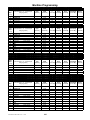
♦ With the courser flashing on the Recipe #, press the + or – button and scroll through all 30 recipes.
When a selection # appears (i.e. “S01”) write this number in the Selection column.
SELECTION LOG TABLE
Recipe #
Beverage Name
Selection
Drink Description
(Sxx is assigned to button
on selection panel)
R01
“FG Coffee”
Fresh Ground Bean Coffee
R02
“FG Decaf”
Fresh Ground Dark Coffee
R03
“FG Dark Cof”
Fresh Ground Dark Coffee
R04
“FG Espreso”
Fresh Ground Espresso Coffee
R05
“LG Coffee”
Loose Ground Coffee
R06
“LG Decaf”
Loose Ground Decaf Coffee
R07
“LG Dark Cof”
Loose Ground Coffee
R08
“LG Espreso”
Loose Ground Espresso Coffee
R09
“FD Coffee”
Freeze Dried Soluble Coffee
R10
“FD Decaf”
Freeze Dried Decaf Coffee
R11
“FD DarkGour”
Freeze Dried Dark/Gourmet
R12
“FD Espreso”
Freeze Dried Espresso Coffee
R13
“FD Tea”
Freeze Dried Soluble Tea
R14
“Café Mocha”
[Blend] -Coffee & Coco
R15
“Decaf Mocha”
[Blend] -Coffee & Decaf Coffee
R16
“Café Latte”
[Blend]- Strong Coffee w/Fr-Vanilla <or> Frothy Topping
R17
“DeCafLatte”
[Blend]- Strong Decaf w/Fr-Vanilla <or> Frothy Topping
R18
“Bal Blend”
Balanced Blend - 50/50 Coffee & Decaf
R19
“CofCapcino”
R20
“VanillaNut”
Coffee Cappuccino
[Blend]- Strong Coffee w/Fr-Vanilla & Cream Topping
[Blend]- French Vanilla SGC#1 & Hazelnut
R21
“Café-SGC#2”
R22
“Coco-SGC#2”
[Blend]- Café + (name of product in SGC#2 canister)
(Example: Café-Hazelnut)
[Blend]- Coco & (name of SGC#2)
R23
“FrenchCoco”
[Blend]- French Vanilla SGC#1 & Coco
R24
“Café-SGC#3”
[Blend]- Coffee & (name of SGC#3)
R25
“FR-Vanilla”
SGC #1 – French Vanilla
R26
“SGC 2”
Soluble Gourmet Coffee #2
R27
“SGC 3”
Soluble Gourmet Coffee #3
R28
“SGC 4”
Soluble Gourmet Coffee #4
R29
“Soup”
Soup (soluble non-particle)
R30
“Chocolate” or
“Creamy Coco”
Chocolate
Creamy Chocolate (w/frothy topping)
Automatic Products
223 V3.0
2/2004
401
PART # 27500015
Operational Set-Up
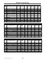
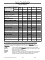
GRAM THROW INSTRUCTIONS
223 RECOMMENDED GRAM THROWS
8 oz Cups
10 oz Cup 12 oz Cups
Coffee
8 - 8.5
10 – 12
12 - 13
Lightener
2 - 2.5
3–4
4-5
Sugar
6.5 – 7
7 – 10
10 - 12
FD Coffee
1.5
2 – 2.5
2 – 3.5
FD Tea
1
1 – 1.5
1.5 - 2
FB Tea
2-3
3 – 3.5
4 – 4.5
Soup
4 - 5.
5 – 5.5
6 – 6.5
Chocolate
24 – 26
28 - 31
33 - 36
SGC
18 – 22
24 - 27
28 - 30
Ingredient Gram Throw Specifications
Examine your ingredient package for ingredient amounts. Use
product manufacturer recommendations for ingredient throws. All
gram throws below are approximations. Always take three test
vends and average for best accuracy, except for products like
chocolate where the product quantity exceeds scale capacity.
Some lightener products are super fine and will clog louvers in
spout. Soluble Gourmet coffees must use 180 RPM motors to
deliver a sufficient amount of product during the allotted time.
Prior to measuring product, ensure the gram scale is properly
adjusted. To zero adjust the gram scale place a nickel on the
scale and set weight for exactly five grams.
♦ 454 GRAMS = ONE POUND
NOTES:
• Different freeze-dried / instant coffees can have different flow characteristics. Remove louvers from
spout or replace spout with louvers as necessary.
• Soluble Gourmet Coffees MUST USE 180 RPM MOTOR to deliver sufficient product during the allotted
cycle time.
• Zero or Tare set you scale meter before starting – Tip: nickel weighs exactly 5 grams
• There are 30 pre-programmed Recipes from R-01 to R-30 (exclude R-31 for the Cleaning Recipe)
• The Gram settings are for Large Cups only. The duration times are for Large Cups only. The logic board
automatically scales the small cups gram settings down.
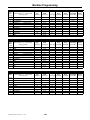
Sample Recipe: “R-30 Chocolate S15”
“Chocolate”
Entry
Step
[< or >]
1
FUNCTION
Press [< or >]
(Do Not Press + or – unless
changing recipe structure)
VALVE- 01
2
WHIPPER-01
3
4
WAIT
CHOCOLATE
5
END
HOT CHOCOLATE
Ingredient
Type
[Press * ]
DURATION
TIME
[Press F2]
[Press F3]
Water In
Delay
[Press F4]
--
10.30
--
--
--
11.78
--
--
–
01.10
--
P
05.55
--
01.00
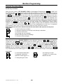
1) Depress the ENTER key and depress the > key until the
Beverage Definition Menu is displayed.
2) When Beverage Definition is displayed depress ENTER .
Depress the > key until Recipe Definition is displayed and
depress ENTER.
“R-01
FG COFFEE
S01”
R-01 = Recipe Number”
FG COFFEE = Beverage Name
S01 = Selection #1 on front panel
3) With the cursor at “R-01”, depress the + or - key to view
the desired recipe.
4) Depress the ENTER key. At this point you have entered the
desired recipe.
5) Depress the > key until the desired ingredient has been
reached (i.e., LG Coffee, Chocolate, etc.).
Automatic Products
223 V3.0
2/2004
Modifier
XtraStrong
Delay
[Press F5]
--
Pressure
Relief Delay
[Press F6]
Brewer
Speed
[Press F7]
--
--
--
--
--
--
--
--
--
10
--
--
--
--
--
--
--
--
--
6) Place the gram scale measuring device under the
appropriate canister to be grammed.
7) Depress either cup switch on the front of the machine to
dispense the product into the measuring device. Place the
dispensed product onto the scale for weighing. If ingredient
displayed needs to be increased or decreased; depress the
F2 key to view the duration time.
8) Depress the numeric keypad and enter the desired duration
time and depress ENTER.
9) Follow step #7 & #8 as needed. These steps should be
followed for all recipes.
402
PART # 27500015
Operational Set-Up
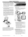
CUP CABINETS
1) Prepare the cup cabinets for the cups to be used.
2) Usually the cup cabinets are preset at the factory when the
correct cup models are specified on the order spec sheet.
Refer to the cup size and model sticker placed on the lock
side of the cup cabinet.
3) If the cups are not set-up correctly please refer to the
service manual for detailed information regarding complete
cup cabinet set-up (i.e., cup ring, spirals, cup base
assembly, and guide bar/rail).
4) Make sure the cups are programmed in the software
correctly by performing the following steps:
a. Depress the ENTER key and depress the > key until the
Beverage Definition Menu is displayed.
b. Depress the ENTER key and depress the > key until the set
cup sizes sub-menu is displayed.
c. Depress the ENTER key and the following will be displayed:
“ SIZE S 1 12.0 ”
d. S (cup size) 1 (cabinet #)
12 (fluid ounces for cup)
e. With the cursor flashing on the cup size (S or L). Depress
the + or – key to toggle the cup size to determine where
the cups are programmed.
f. Depress the > key to move the flashing cursor into the
cabinet field. Depress + or – key in order to change the
cup cabinet the cups are programmed for in the software.
The following will be displayed 1 for cabinet 1 (smaller
cup cabinet closest to the machine), 2 (front larger cup
cabinet closest to the door), or 1+2 for both cup cabinets.
g. Depress the > key to move the flashing cursor into the fluid
ounce field. Enter the actual cup volume size via the
numeric keypad associated with steps d & e above.
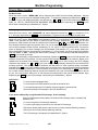
SET PRICES
1) Press F4 - Set Price Menu
2) Press ENTER to access Set Price menu.
3) Sample Display:
"SEL-01 SIZE-S
=00.50"
4) Press8button to move cursor between Selection #, Cup
Size & Price Setting.
5) Press + button to toggle the cup size between "S" (small) or
"L" (large) to be priced (note: "R" setting is not use).
6) Press 8 to move cursor to price setting. Use numbered
keypad or “+” or “–“ to set cup price.
7) Press 8 to move cursor to selection number.
8) Press (+ or –) to choose the selection # to be priced at size
indicated.
9) Press ENTER to register the setting for selection displayed.
Repeat above steps to price other selections.
10) Press ESC to save in memory and exit this menu.
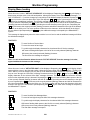
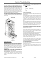
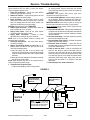
CHECK & ADJUST CUP LIQUID LEVELS
Check the non-blended drinks first such as; Chocolate, French
Vanilla, SGC, etc. For these drinks, adjust the water levels by
turning the metering screw on the corresponding water valve
(see diagram below).
For all other drinks, the water levels must be set by the duration
time in the corresponding drink recipe.
Motors and Valves are numbered from left to right:
♦
Once the above steps are performed
the machine is ready for operation.
HOT WATER TANK
BV = BREWER WATER VALVE
BV 12
V = COMMODITY WATER VALVES
V1
V2
V3
V4
V5
A = AUGER MOTORS
A1
A2
A3
A4
A5
A6
A7
W1
W2
W3
W4
W5
W6
W7
W = WHIPPER MOTORS
Automatic Products
223 V3.0
2/2004
404
PART # 27500015
Operational Set-Up
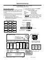
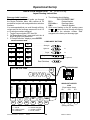
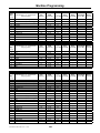
RACK CONFIGURATION “ B “ (1-2- 4)
Layout Drawing Instructions
3. If “Recipe Definition” displays, press ENTER.
4. The following should display:
“R01 FG COFFE S##”
R01 =
Recipe Number
FG Coffee =
Beverage Name
S## =
Selection Number
5. With curser flashing on the “R” number, press
the + or - button and scroll through all recipes
to determine the selection number “S##”
assigned to the factory set beverage type.
Beverage Label Locations
The following instructions will guide you through
the Recipe Definition Menu that contains all 30
pre-defined recipes with assigned button selection
numbers.
It is recommended that you scroll through all thirty
recipes and list the beverage names next to all 10
or 15 selection numbers assigned.
1. Toggle Power switches OFF then ON.
2. On MasterMenu Panel, press and hold the ¹
button & press F3 at same time.
SELECTION BUTTONS
2
7
12
3
8
13
4
9
14
5
10
15
Strength
Lightener
C1
Sugar
C2
Sugar-Sub
C2
Start Switches
BREWER ASM
HOT WATER TANK
V1
V2
V3
W1
W2
W4
V
3
P
P
A5
C6
223 V3.0
2/2004
SWING-OUT HOPPER ASM
(TRIPLE HOPPER SETUP)
9
10
11
Sugar-Sub
FD Decaf
FD Gourmet
Note: Canister #8 not used
V = VALVE
A = AUGER 180 RPM
BV = Brew valve
C = AUGER 51 RPM
W = WHIPPER
P = PLUG, VALVE
Automatic Products
C7
FD Tea
A4
Sugar
SGC #2
French
Vanilla
SGC #1
Chocolate
A3
V
2
BV
12
Lightener
V
1
AUGER MOTORS
A1
A2
(Optional)
404
DECAF
COFFEE
11
DARK
COFFEE
6
REGULAR
COFFEE
1
COMPLIMENT BUTTONS
(Swung-Out View)
PART # 27500015
Operational Set-Up
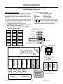
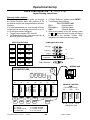
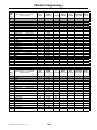
RACK CONFIGURATION “ C “ (1-1- 2- 3)
Layout Drawing Instructions
Beverage Label Locations
The following instructions will guide you through
the Recipe Definition Menu that contains all 30
pre-defined recipes with assigned button selection
numbers.
It is recommended that you scroll through all thirty
recipes and list the beverage names next to all 10
or 15 selection numbers assigned.
1. Toggle Power switches OFF then ON.
2. On MasterMenu Panel, press and hold the ¹
button & press F3 at same time.
SELECTION BUTTONS
1
6
11
2
7
12
3
8
13
4
9
14
5
10
15
3. If “Recipe Definition” displays, press ENTER.
4. The following should display:
a) “R01 FG COFFE S##”
b) R01 =
Recipe Number
c) FG Coffee =
Beverage Name
d) S## =
Selection Number
5. With curser flashing on the “R” number, press
the + or - button and scroll through all recipes
to determine the selection number “S##”
assigned to the factory set beverage type.
COMPLIMENT BUTTONS
Strength
Lightener
C1
Sugar
C2
Sugar-Sub
C2
(Optional)
Start Switches
HOT WATER TANK
BREWER ASM
V
1
V
2
BV
12
V
3
V
4
P
AUGER MOTORS
V1
V2
V3
V4
W1
W2
W3
W5
223 V3.0
2/2004
405
REGULAR
COFFEE
DECAF
COFFEE
SWING-OUT HOPPER ASM
(Triple Hopper Setup)
A9
A10
A11
Sugar-Sub
FD Decaf
FD Tea
FD Gourmet
Note: Canister #8 not used
V = VALVE
A = AUGER 180 RPM
W = WHIPPER
C = AUGER 51 RPM
P = PLUG, VALVE
Automatic Products
C7
DARK
COFFEE
A6
Lightener
A5
Sugar
A4
SGC #3
A3
SGC #2
A2
French Vanilla
SGC #1
Chocolate
A1
(Swung-Out View)
PART # 27500015
Operational Set-Up
RACK CONFIGURATION “ D “ (1 - 2 - 2)
Layout Drawing Instructions
Beverage Label Locations
The following instructions will guide you through
the Recipe Definition Menu that contains all 30
pre-defined recipes with assigned button selection
numbers.
It is recommended that you scroll through all thirty
recipes and list the beverage names next to all 10
or 15 selection numbers assigned.
1. Toggle Power switches OFF then ON.
2. On MasterMenu Panel, press and hold the ¹
button & press F3 at same time.
3. If “Recipe Definition” displays, press ENTER.
SELECTION BUTTONS
1
6
11
2
7
12
3
8
13
4
9
14
5
10
15
4. The following should display:
“R01 FG COFFE S##”
R01 =
Recipe Number
FG Coffee =
Beverage Name
S## =
Selection Number
5. With curser flashing on the “R” number, press
the + or - button and scroll through all recipes
to determine the selection number “S##”
assigned to the factory set beverage type.
COMPLIMENT BUTTONS
Strength
Lightener
C1
Sugar
C2
Sugar-Sub
C2
(Optional)
Start Switches
BREWER ASM
HOT WATER TANK
BV
12
V
1
V
2
V
3
V
4
P
AUGER MOTORS
V4
W1
W2
W4
W6
Note: Canister #8 not used
V = VALVE
A = AUGER 180 RPM
BV = BREW VALVE
C = AUGER 51 RPM
W = WHIPPER
P = PLUG, VALVE
Automatic Products
223 V3.0
2/2004
DECAF
COFFEE
V3
DARK
COFFEE
V2
SWING-OUT HOPPER
ASM
(Triple Hopper Setup)
A9
A10
A11
REGULAR
COFFEE
V1
A7
Lightener
A6
Sugar
A5
SGC #4
A4
SGC #3
A3
SGC #2
A2
French Vanilla
SGC #1
Chocolate
A1
(Swung-Out View)
406
PART # 27500015
Operational Set-Up
RACK CONFIGURATION “ E “ (1-1-1- 4)
Layout Drawing Instructions
4. The following should display:
“R01 FG COFFE S##”
R01 =
Recipe Number
FG Coffee =
Beverage Name
S## =
Selection Number
5. With curser flashing on the “R” number, press
the + or - button and scroll through all recipes
to determine the selection number “S##”
assigned to the factory set beverage type.
Beverage Label Locations
The following instructions will guide you through
the Recipe Definition Menu that contains all 30
pre-defined recipes with assigned button selection
numbers.
It is recommended that you scroll through all thirty
recipes and list the beverage names next to all 10
or 15 selection numbers assigned.
1. Toggle Power switches OFF then ON.
2. On MasterMenu Panel, press and hold the ¹
button & press F3 at same time.
3. If “Recipe Definition” displays, press ENTER.
SELECTION BUTTONS
1
6
11
2
7
12
3
8
13
4
9
14
5
10
15
COMPLIMENT BUTTONS
Strength
Lightener
C1
Sugar
C2
Sugar-Sub
C2
(Optional)
Start Switches
BREWER ASM
HOT WATER TANK
V
12
V
1
V
2
V
3
V
4
P
V1
V2
V3
V4
W1
W2
W3
W4
FD Tea
Sugar-Sub
FD Decaf
FD Gourmet
Note: Canister #8 not used
V = VALVE
A = AUGER 180 RPM
W = WHIPPER
C = AUGER 51 RPM
P = PLUG, VALVE
Automatic Products
223 V3.0
2/2004
C7
407
SWING-OUT HOPPER
ASM
(Triple Hopper Setup)
9
10
11
DECAF
COFFEE
C6
DARK
COFFEE
A5
Lightener
A4
Sugar
A3
SGC #2
A2
French Vanilla
SGC #1
Chocolate
A1
REGULAR
COFFEE
AUGER MOTORS
(Swung-Out View)
PART # 27500015
Operational Set-Up
RACK CONFIGURATION “ F “ (1-1-1-1- 3)
Layout Drawing Instructions
Flavor Label Locations
The following instructions will guide you
through the Recipe Definition Menu that
contains all 30 pre-defined recipes with
assigned button selection numbers.
It is recommended that you scroll through all
thirty recipes and write down the flavor type
next to every selection number assigned.
1. Toggle Power switches OFF then ON..
2. On MasterMenu Panel, press and hold
the ¹ button & press F3 at same time.
3. If “Recipe Definition” displays, press ENTER.
4. The following should display:
“R01 FG COFFE S##”
R01 =
Recipe Number
FG Coffee =
Flavor Type
S## =
Selection Number
5. With curser flashing on the “R” number,
Press the + or - button and scroll through all
recipes to determine the “S” selection
number for factory assigned Flavor type.
SELECTION BUTTONS
COMPLIMENT BUTTONS
1
6
11
2
7
12
3
8
13
4
9
14
5
10
15
Strength
Lightener
C1
Sugar
C2
Sugar-Sub
C2
(Optional)
Start Switches
BREWER ASM
HOT WATER TANK
V
3
V
4
V
5
AUGER MOTORS
V1
V2
V3
V4
V5
W1
W2
W3
W4
W5
A6
223 V3.0
2/2004
SWING-OUT HOPPER ASM
(Triple Hopper Setup)
A10
A11
A9
REGULAR
COFFEE
Sugar-Sub
FD Tea
FD Decaf
FD Gourmet
Note: Canister #8 not used
V = VALVE
A = AUGER 180 RPM
BV =BREW VALVE
C = AUGER 51 RPM
W = WHIPPER
P = PLUG, VALVE
Automatic Products
C7
Lightener
A5
Sugar
A4
SGC #3
/ Froth Topping
A3
SGC #2
A2
French Vanilla
SGC #1
Chocolate
A1
408
DECAF
COFFEE
V
2
DARK
COFFEE
V
1
BV
12
(Swung-Out View)
PART # 27500015
Operational Set-Up
RACK CONFIGURATION “ G “ (1-1-1-1-1- 2)
Layout Drawing Instructions
4. The following should display:
“R01 FG COFFE S##”
R01 =
Recipe Number
FG Coffee =
Beverage Name
S## =
Selection Number
5. With curser flashing on the “R” number, press
the + or - button and scroll through all recipes
to determine the selection number “S##”
assigned to the factory set beverage type.
Beverage Label Locations
The following instructions will guide you through
the Recipe Definition Menu that contains all 30
pre-defined recipes with assigned button selection
numbers.
It is recommended that you scroll through all thirty
recipes and list the beverage names next to all 10
or 15 selection numbers assigned.
1. Toggle Power switches OFF then ON.
2. On MasterMenu Panel, press and hold the ¹
button & press F3 at same time.
3. If “Recipe Definition” displays, press ENTER.
SELECTION BUTTONS
7
12
3
8
13
4
9
14
5
10
15
Lightener
C1
Sugar
C2
Sugar-Sub
C2
Start Switches
BREWER ASM
HOT WATER TANK
VB
12
V
3
A5
V1
V2
V3
V4
V5
W1
W2
W3
W4
W5
V
4
V
5
A6
Sugar
A4
SGC #3
SGC #2
French Vanilla
SGC #1
Chocolate
A3
V
2
SGC #4
/ Froth Topping
V
1
AUGER MOTORS
A1
A2
223 V3.0
2/2004
A7
SWING-OUT HOPPER
ASM
(Triple Hopper Setup)
A9
A 10
A11
W6
(Swung-Out View)
Note: Canister #8 not used
V = VALVE
A = AUGER 180 RPM
BV = BREW VALVE
C = AUGER 51 RPM
W = WHIPPER
P = PLUG, VALVE
Automatic Products
(Optional)
409
PART # 27500015
DECAF
COFFEE
2
Strength
DARK
COFFEE
11
REGULAR
COFFEE
6
Lightener
1
COMPLIMENT BUTTONS
Operational Set-Up
RACK CONFIGURATION “ H “ (1-1-1 -2 -2)
Layout Drawing Instructions
Beverage Label Locations
The following instructions will guide you through
the Recipe Definition Menu that contains all 30
pre-defined recipes with assigned button selection
numbers.
It is recommended that you scroll through all thirty
recipes and list the beverage names next to all 10
or 15 selection numbers assigned.
1. Toggle Power switches OFF then ON.
2. On MasterMenu Panel, press and hold the ¹
button & press F3 at same time.
SELECTION BUTTONS
3. If “Recipe Definition” displays, press ENTER.
4. The following should display:
“R01 FG COFFE S##”
R01 =
Recipe Number
FG Coffee =
Beverage Name
S## =
Selection Number
5. With curser flashing on the “R” number, press
the + or - button and scroll through all recipes
to determine the selection number “S##”
assigned to the factory set beverage type.
COMPLIMENT BUTTONS
1
6
11
2
7
12
Lightener
C1
3
8
13
Sugar
C2
Sugar-Sub
C2
4
9
14
5
10
15
Strength
(Optional)
Start Switches
BREWER ASM
HOT WATER TANK
VB
12
V4
W1
W2
W3
W4
223 V3.0
2/2004
Lightener
SWING-OUT HOPPER
ASM
(Triple Hopper Setup)
A9
A10
A11
W6
(Swung-Out View)
Note: Canister #8 not used
V = VALVE
A = AUGER 180 RPM
BV = BREW VALVE
C = AUGER 51 RPM
W = WHIPPER
P = PLUG, VALVE
Automatic Products
A7
DECAF
COFFEE
V3
A6
DARK
COFFEE
V2
V
5
REGULAR
COFFEE
V1
A5
V
4
Sugar
A4
V
3
SGC #4
/ (SGC 3
A3
SGC #2
/ Froth
Topping
French Vanilla
SGC #1
Chocolate
AUGER MOTORS
A1
A2
V
2
SGC #3
/ (SGC #2)
V
1
410
PART # 27500015
Operational Set-Up
RACK CONFIGURATION “ FDX “ FREEZE DRIED EXTENSION
Layout Drawing Instruction
Beverage Label Locations
The following instructions will guide you through
the Recipe Definition Menu that contains all 30
pre-defined recipes with assigned button selection
numbers.
It is recommended that you scroll through all thirty
recipes and list the beverage names next to all 10
or 15 selection numbers assigned.
6. Toggle Power switches OFF then ON.
7. On MasterMenu Panel, press and hold the ¹
button & press F3 at same time.
8. If “Recipe Definition” displays, press ENTER.
9. The following should display:
“R01 FG COFFE S##”
R01 =
Recipe Number
FG Coffee =
Beverage Name
S## =
Selection Number
10. With curser flashing on the “R” number, press
the + or - button and scroll through all recipes
to determine the selection number “S##”
assigned to the factory set beverage type.
SELECTION BUTTONS
1
6
11
2
7
12
3
8
13
4
9
14
5
10
15
COMPLIMENT BUTTONS
Strength
Lightener
C1
Sugar
C2
Sugar-Sub
C2
(Optional)
Start Switches
HOT WATER TANK
P
V
4
V
5
V1
V2
V3
V5
W1
W2
W3
W4
A6
C7
Lightener
A5
Sugar
SGC #3
A4
/ Froth Topping
A3
SGC #2
Chocolate
French Vanilla
SGC #1
A2
Sugar-Sub
C8
AUGER MOTORS
A1
FDX - EXTENSION RACK
C9
C10
C11
FD Decaf
V
3
FD Dark
(optional)
V
2
FD Coffee
V
1
V4
W5
FD Tea
FD Gourmet
Note: FDX Shown with Rack F
V = VALVE
A = AUGER 180 RPM
W = WHIPPER
C = AUGER 51 RPM
Water Line
P = PLUG, VALVE
Automatic Products
223 V3.0
2/2004
411
PART # 27500015
Machine Programming
Quick Set-Up Reference
The APi 223 Hot Beverage Machine is shipped with minimal preset recipes allowing the customer to determine
which soluble gourmet coffees are to be used. Listed below is a quick setup reference guide required prior to
installing the machine onto location:
NAME ASSIGNMENT
Press * and F2
Press
Press
Press
Press
Press
Press
ENTER to access device name
+ or – to scroll through any of the device names with an assigned ingredient name.
> to move the courser to the ingredient name that needs to be changed.
+ or – to reassign an ingredient name to the device name displaying.
ENTER to register name change
ESC to exit this menu
RECIPE DEFINITION –
Press * and F3 at same time
Press ENTER to access device name (Displays: " R-01 FB Coffee S-## “)
The Recipe Number ("R-01"), Beverage Name and Selection Number ("S-02") will be displayed.
With cursor at "R-01", Press > to scroll to the Selection Number ("S-02").
Press + or – to assign the proper selection number to the proper recipe.
(Note: The Selection Number displaying will also light the related button on the customer selection
panel.)
Press ENTER to register setting or ESC to step back.
Press ESC twice to save all changes in memory and to exit this menu.
SET DRINK SIZES
Press ENTER to access MasterMenu™.
Press the > until “BEVERAGE DEFINITION” appears on the display.
Press ENTER to access.
Press the > until “SET DRINK SIZES” appears on the display.
Press ENTER to access.
Displays: “SIZE S 1 8.0” (“1” = low capacity cup cabinet – “2” = High capacity cup cabinet)
Press > to scroll courser from Cup Size (Size S) to Dispenser # (1) to Drink Volume (8.0).
Press + or – to toggle cup size, or to change dispenser # or to increase or decrease volume setting.
Press ENTER to register setting or ESC to step back.
Press ESC twice to save all changes in memory and to exit this menu.
SET PRICES
Press F4 - Set Price Menu
Press ENTER to access Set Price menu.
(Sample Displays: "08 CafeMocha 00.50")
Press > to move cursor between Selection #, Selection Name, & Price Setting.
Press > to move cursor to price setting. Use numbered keypad or + or – to set cup price.
Press > to move cursor to selection number.
Press + or – to choose the selection to be priced.
Press ENTER to register the setting for selection displayed. Repeat above steps to price other selections.
Press ESC to save in memory and exit this menu.
Automatic Products 223 V3.0 04/2004
500
Machine Programming
Function Keys
To access the following "F" function buttons,
you should be in the enhanced program
mode. This mode is automatically accessed
when the main door is opened or can be
accessed by depressing the Service Switch
located on the main door. The display should
be showing either;
F2
F3
F4
F5
F6
View MIS
ClearMIS
Clear Errors
Recipe Define
"ENTER FOR MASTERMENU" or
"XX ERRORS"
Print MIS
Motor Test
Note: upon depressing the service switch, you
may need to wait up to 15 seconds to allow
for the initialization / scanning process to
complete.
F7
Config. Load
Aux. Function
Press F1 - View MIS Menu (accountability)
• Press < or > to scroll through the MIS data.
• Press ESC to exit this menu.
View Errors
Name Assign
Set Price
Clean Cycle
Test Vend
Valve Test
*
(Secondary Level)
Press F5 - PRINT MIS DATA
• Press ENTER twice to view
"PRINT SHORT LIST"
• Press + or – to choose either
"SHORT" or "FULL" list to print.
• Press ENTER to start transmitting data.
• Press ESC to exit this menu.
Press F2 - View Errors Menu
• Press ENTER to View for Errors. The most
current error will appear first.
• Press > to scroll through the error list when
reaching end of list, two audible beeps can be
heard. Pressing F2 when viewing an error will
cause extended diagnostics to be displayed.
• Press ESC to exit this menu.
Press F6 - Test Vend Menu
• Press to toggle between "N" and "Y".
• Press ENTER and the front selection panel
becomes active until main door is closed.
• Press ESC to exit this menu.
Press F3 - Clear Errors Menu
• Press + to toggle from "N" to "Y".
• Press ENTER to clear Errors.
• Press ESC to exit.
Press F7 - CONFIGURATION LOAD
• Press ENTER then < or > to view
"MASTERMENU ONLINE"
"TMU UPLOAD"
"TMU DOWNLOAD"
• Press ENTER at the desired function above
Press F4 - Set Coffee Price Menu
• Press ENTER to access Set Price menu.
(Sample Displays: "01 FB TEA 00.50")
• Press > to move cursor to price setting. Use
numbered keypad + or – or to set cup price.
• Press > to move cursor to selection number.
• Press + or – to choose the selection to be
priced at size indicated.
• Press ENTER to register the setting for
selection displayed. Repeat above steps to
price other selections.
• Press ESC to save in memory and exit this
menu.
Automatic Products 223 V3.0 04/2004
F1
•
Press + or – to choose either Options,
Recipes, or Languages to load.
•
•
•
Press > to move courser to "N" position
Press + to toggle from "N" to "Y".
Press ENTER to start process. Insert loading
device into socket plug and hold until display
indicates "TRANSFER COMPLETE”.
Press ESC to exit this menu
•
501
Machine Programming
Function Keys
The second level of Menu items can be accessed by pressing and holding in the key while pressing one
of the function buttons F1 - F7.
Press * and F1 - Clear MIS Data
•
•
•
•
•
Press + to toggle from "N" to "Y"
Press ENTER to initiate MIS reset process
Press ESC to exit
•
•
Press * and F2 - Name Assignments
•
•
•
•
•
•
•
Press ENTER to access device name
Press + or – to scroll through any of the device
names with assigned ingredient names.
Press > to move cursor to ingredient name that
needs to be changed.
Press + or – to reassign an ingredient name to
the device name displaying.
Press ENTER to register name change
Press ESC to exit this menu
Press * and F4 - Cleaning Cycle
• Press ENTER to access Manual Cleaning
Cycle
• Press + to change setting to "Y"
• Press ENTER to start cleaning process
• Press ESC to exit this menu
Press * and F5 - Motor Test
• Press ENTER to access settings.
• Press > to scroll to motor name testing.
• Press ENTER to start the test
• Press ESC to exit
Press * and F3 - Recipe Definition
(Note: the following instructions are for checking or
modifying duration times only.)
• Displays: " R- 01 FB COFFEE S-01 "
The Recipe Number ("R- 01"), Beverage Name and
Selection Number ("S- 01") will display.
• With cursor at "R-01” Press + or – to scroll to
the Recipe Name you wish to go into & check
or modify a duration time.
(Note: The Selection Number displayed will also
light the related button on the customer selection
panel.)
• Press ENTER when at desired Recipe Name.
You are now in the recipe timing steps for this
beverage.
Press * and F6 - Valve Test
• Press ENTER to access settings.
• Press > to scroll to valve name testing.
• Press ENTER to start test
• Press ESC to exit.
Press * and F7 - Auxiliary Functions
(NOTE: Used to check and test the following
devices: Cup motors, spirals, cupwell spout, & vend
door.)
• Press ENTER to access Auxiliary Functions
test.
• Press > to scroll to the device functions to test
• Press ENTER to run the device function. When
test is completed, the display will indicate;
"TEST COMPLETE" or "TEST FAILED".
• Press ESC to exit.
•
Press > to move through the numbered recipe
steps until reaching the device or ingredient
name that the duration time is in.
(Note: ingredient names starting with alpha letters
are as follows: A = Auger, V = Valve, W = Whipper,
C = Coffee, LG = Loose Ground, and G =
Grinder)
Automatic Products 422 V3.0 11/02
Press {F2} to view duration time setting. Use
numbered keypad to change setting.
Press ENTER to register new setting or ESC
to step back.
Press {F3} to set modifier if applicable. Use
numbered keypad to change setting.
Press ENTER to register setting or ESC to
step back.
Press ESC twice to save all changes in
memory and to exit this menu.
502
Machine Programming
Operation System
Introduction
The APi MasterMenu System is user friendly and provides a common look and feel across all menu items. The
system allows the user to move freely through the menus and provides ease of insertion, modification, and
deletion of operational parameters and data. In addition, the system provides the user with status and
diagnostics messages to aid in the use and service of the machine.
Operational Mode
The Operational mode provides the machine with the ability to vend products. The machine is in Operational
Mode whenever the main cabinet door of the machine is closed. Upon opening of the main cabinet door, the
machine will go into the Enhanced Operation Mode and will display "ENTER FOR MASTER MENU". The
machine remains in Operational Mode until the ENTER key is depressed at which time it will enter the Service
Mode. This allows for vends to occur while the main cabinet door of the machine is open and the user has not
yet entered Service Mode by depressing ENTER the key. This is referred to as Enhanced Operational Mode
that is different from Operational Mode in that the Function keys and Payout keys are active. If any key other
than the ENTER key is depressed, it will perform its function and return the machine to Enhanced Operational
Mode when complete.
The Service Menu provides access to all configurable items in the machine as well as retrieval of MIS
information. The Service Menus shall only be available when the machine is in Service mode.
Service Mode
Service Mode provides the ability to configure the machine. When the main door is opened, the service switch
will deactivate and "ENTER FOR MASTERMENU" will be displayed. If no errors have been logged, or "NNN
ERRORS" in the case where errors exist (“NN" is the number of errors). Depressing the ENTER key will step
you into the Service Mode and will display "MIS" for this menu. Depressing the ENTER key, the machine
returns to Operational Mode whenever the main cabinet door is closed. When the main cabinet door is closed,
the machine scans for all recipes configured in the program. If Recipe Mismatch is displayed; an error has been
found in the recipe program. Entering into the diagnostics program will allow for the incorrect recipe number to
be displayed.
Automatic Products 422 V3.0 11/02
502
Machine Programming
MasterMenu™
The MasterMenu™ System provides a set of text based Service Menus which allows interface to all functions of
the machine. Menus appearing at the upper most level of the menu system are referred to as Menu Headings.
Menus appearing under the Menu Headings are referred to as Menu Items.
MasterMenu™ Structure Diagram
MasterMenu
MIS
Menu Heading
View Interval MIS
View Historical MIS
Print MIS Data
Clear MIS Data
Tube Fill
SoftWare Rev.
Setup
Menu Heading
Bill Escrow
Free Vend
Winner Vend
Multiple Vend
Force Vend
Set Max Payout
Set Payout Type
Temp Override
Own Cup Disc.
Keyless Executive
Executive Vend
Energy Shaver
Configuration
Menu Heading
Machine Config.#
Configuration Load
Calibration
Set Temperature
Set Function Keys
Cup Substitution
Printer Setup
Automatic Products 422 V3.0 11/02
Beverage
Definition
Menu Heading
Recipe Definition
Name Creation
Name Assignment
Set Drink Size
Diagnostic
Menu Heading
Time Functions
Menu Heading
View Errors
Clear Errors
Test Vend
Test Motors
Test Brewer
Test Valve
Test Whipper
Water Tank Check
Auxiliary Functions
Discount Time
Price Assign
Discount Options Check Prices
Time / Date
Shutdown Day/ Time
Shutdown Options
Cleaning Cycle
Test Cup Drop
Test spiral
Test Spout
Test Vend door
503
Price
Menu Heading
Security
Menu Heading
Display
Menu Heading
Serial #
Machine Model
Machine Loc.
Machine Asset
Password Def.
Password Prompt
Set Security Levels
Machine Reset
Set Menu Order
Set Language
Set User Msg.
Set Out of Service
Set After Sale Msg.
Machine Programming
Quick Reference Directory for MasterMenu™
The following is a quick reference for the keys on the MasterMenu™ keypad.
F1
« F7 Are the quick path Function Keys used when in the Enhanced Mode to perform and retrieve
programming information through some of the most commonly used functions in the machine.
When in the Recipe Definition Mode, these keys are used to perform recipe time settings.
*
Depressing the (star) * key while depressing one of the function keys F1 through F7 are specific to
the second level of menu heading/items currently active. The * key can also be used for wildcarding in
the pricing of all the small or large size cups at the same price, thus saving time. This key also is used
in the Recipe Definition Menu to set Ingredient type.
.0
The four coin payout buttons are used to pay coins out of an L+ or a standard US (dummy mech). The
four coin payout buttons are .05 , .10 , .25 , and 1.00. The four coin payout buttons may also be
used to enter pricing information while assigning prices. For example, to enter a price of $.65, pressing
the .25 key twice , the .10 key once and the .05 key once, would result in .65 appearing on the
display. See the Price Setting section for additional information. The four coin payout buttons may also
be used to enter pricing information while assigning prices.
ESC
Used for exiting the current menu, escaping from menu functions without saving any
changes if the ENTER Key was not depressed before ESC key.
ENTER
Used to choose a menu heading and to commit to insertions/modifications/deletions made in
a menu item.
< AND >
Used to move the cursor from its current position to the position directly to its left or right also
to select the menu heading immediately to the left of the current menu heading.
+ AND –
Used for increasing and decreasing the available choices in a menu .
Note: Anywhere in this manual that the or keys are defined to sequence through
numeric data, the front panel may be used as an alternate input source.
DELETE
Used to delete the character on the current cursor position. Also used to remove a recipe
step when editing a beverage recipe file.
INS
Used to insert a character to the left of the current cursor position. Also used to insert a
recipe step when editing a beverage recipe file.
Note: Depressing a function key will not cause you to enter the MasterMenu™ System.
Automatic Products 422 V3.0 11/02
504
Machine Programming
MIS Menu heading
MIS Description
The MIS menu Heading provides the ability to view MIS data collected during Operational Mode as well as data
collected during specific Service Mode functions such as Test Vends. This menu also provides the ability to print
the MIS data and download the data to the Transportable Memory Module or DEX/UCS hand held computer.
MIS data is stored as both resettable and non-resettable with the exception of Machine Identification Number,
Machine Serial Number, and Software Version Number, which are stored as non-resettable only. This menu
also provides a means of clearing the resettable data. The chart below indicates which vend types will register
for the following MIS data fields:
Vend Type
Field
# VENDS
$ VENDS
# / SELECTION
$ / SELECTION
# / TEST VEND
$ / TEST VEND
# / DISCOUNT
$ / DISCOUNT
(Amount)
# / WINNER
$ / WINNER
(Sale Price)
#/EXECUTIVE
$/EXECUTIVE
# / FREE VEND
$ / FREE VEND
# / TOKEN
$ / TOKEN
Normal Discount Token or Discount &
Winner Winner or Token
*
*
*
*
*
*
*
*
*
*
*
*
*
*
*
*
Executive Test Free Token
vend vend Vend
*
*
*
*
*
*
*
*
*
*
*
*
*
*
*
*
*
*
*
*
*
*
*
*
*
* Indicates which field is updated for a given vend type.
(List Price - Discount Amount if any = Sale Price)
Note: $Winner accumulates sale prices of Winners. If the Winner is also Discounted, the vend is counted
in #Discount and the discount is accumulated in $Discount.
View MIS Data Menu
Depressing the key when the MasterMenu™ indicates "VIEW MIS DATA" on the display will cause the display
to be updated with the first MIS data item, "TOTAL CASH SALES". The and keys are used to sequence through
the historical MIS data list defined in the following table:
FASTPATH
ENTER
To enter view MIS, the display will prompt the total cash sales.
< Or >
To next MIS data.
ESC ESC
To exit.
Depressing F1 will give you direct access to the View MIS menu without entering MasterMenu™.
Automatic Products 422 V3.0 11/02
505
Machine Programming
MIS Menu heading
Resettable and Non-Resettable MIS data in DEX format
NAME
TOTAL VALUE OF SALES
# OF VENDS
VALUE OF DISCOUNTED PAID SALES
# OF DISCOUNTED PAID SALES
VALUE OF TEST VENDS
# OF TEST VENDS
1
# FREE VENDS
1
VALUE FREE VENDS
COIN MECH SERIAL NUMBER
COIN MECH MODEL NUMBER
COIN MECH FIRMWARE REVISION
VALUE OF CASH SALES
# OF CASH SALES
VALUE OF BILLS STK'D
VALUE OF CASH IN
VALUE OF COINS TO TUBES
VALUE OF COINS ROUTED
TO THE CASH BOX
VALUE OF CASH DISPENSED
VALUE OF CASH MANUALLY DISPENSED
VALUE OF DISCOUNT FOR
DISCOUNTED VENDS
# OF DISCOUNTED VENDS
VALUE OF CASH OVERPAY
VALUE OF PAY VEND EXACT CHANGE
VALUE OF CASH FILLED
CURRENT VALUE OF COINS IN TUBES
MACH ID #
MACH ASSET #
MACH LOCATION
MACH SERIAL #
MACHINE VERSION #
DECIMAL POINT POSITION
TELEPHONE COUNTRY CODE
CHANGER CURRENCY CODE
SYSTEM DATE
SYSTEM TIME
BILL VALIDATOR SERIAL NUMBER
BILL VALIDATOR MODEL NUMBER
BILL VALIDATOR FIRMWARE REVISION
CONTROL BOARD SERIAL NUMBER
CONTROL BOARD MODEL NUMBER
CONTROL BOARD FIRMWARE REVISION
VALUE OF DISCOUNT FOR
EXECUTIVE VENDS
# OF EXECUTIVE VENDS
VALUE OF DISCOUNT FOR
KEYLESS EXECUTIVE VENDS
# OF KEYLESS EXECUTIVE VENDS
1
VALUE FREE VENDS ON SMALL CUPS
1
# OF FREE VENDS ON SMALL CUPS
1
VALUE FREE VENDS ON LARGE CUPS
1
# OF FREE VENDS ON LARGE CUPS
# OF WINNER VENDS
VALUE OF WINNER VENDS
# OF DISCOUNTED VENDS
VALUE OF LARGE VOLUME DRINKS
# OF LARGE VOLUME DRINKS
VALUE OF SMALL VOLUME DRINKS
# OF SMALL VOLUME DRINKS
VALUE OF LARGE VOLUME NO CUP DRINKS
DISCOUNT OF LARGE VOLUME NO CUP
DRINKS
# OF LARGE VOLUME NO CUP DRINKS
VALUE OF SMALL VOLUME NO CUP DRINKS
DISCOUNT OF SMALL VOLUME NO CUP
DRINKS
# OF SMALL VOLUME NO CUP DRINKS
VALUE OF VEND TOKEN SALES
# OF VEND TOKEN VENDS
VALUE OF VALUE TOKEN SALES
# OF VALUE TOKEN VENDS
CASHLESS SERIAL NUMBER
CASHLESS MODEL NUMBER
CASHLESS FIRMWARE REVISION
# OF CASHLESS VENDS
VALUE OF CASHLESS VENDS
VALUE CREDITED TO CASHLESS
VALUE OF CASHLESS DISCOUNTS
# OF CASHLESS DISCOUNTS
VALUE OF CASHLESS SURCHARGES
# OF CASHLESS SURCHARGES
VALUE OF VENDS BY CABINET
# OF VENDS BY CABINET
VALUE OF VENDS BY COFFEE SEL AND
SIZE
Automatic Products 422 V3.0 11/02
DEX HEADER FIELD
DEX FIELDS
HISTORICAL
INTERVAL
(Non-Resettable)
(Resettable)
VA101
VA102
VA105
VA106
VA201
VA202
VA302
VA301
CA101
CA102
CA103
CA201
CA202
CA308
CA305
CA307
CA306
CA203
CA204
CA304
CA301
CA303
CA302
CA403
CA404
CA702
CA401
CA402
CA701
CA703
CA801
CA901
CA1001
MA501 = "EXECUTIVE"
CA704
CA802
CA902
CA1002
CA1501
ID102
ID106
ID104
ID101
ID103
ID401
ID402
ID403
ID501
ID502
BA101
BA102
BA103
CB101
CB102
CB103
MA502
MA504
MA501 = "KEYLESS EXEC"
MA503
MA502
MA505
MA504
MA501 = "LARGE NO CUP"
MA503
MA502
MA503
MA502
MA503
MA503
MA502
MA502
MA502
MA503
MA502
MA503
MA502
MA505
MA504
MA505
MA504
MA505
MA505
MA504
MA503
MA504
MA505
MA504
MA505
MA504
MA501 = "SMALL NO CUP"
MA503
MA502
MA505
MA504
MA503
TA201
TA202
TA205
TA205
DA101
DA102
DA103
DA202
DA201
DA401
DA503
DA504
DA507
DA508
PA202
MA505
TA203
TA204
TA207
TA208
PA201
PA202
PA203
PA204
SAME AS CB101 FOR NOW
AP120
MA501 = "FREE SMALL CUP"
MA501 = "FREE LARGE CUP"
MA501 = “WINNER VENDS”
MA501 = "DISC"
MA501 = "LARGE VOLUME"
MA501 = "SMALL VOLUME"
PA101 = (COFFEE or
SNACK)
PA101 = (COFFEE # X)
(# = 1 TO 15)
(X = S,L)
PA102 = PRICE
506
VA103
VA104
VA107
VA108
VA203
VA204
VA304
VA303
DA204
DA203
DA401
DA501
DA502
DA505
DA506
PA204
Machine Programming
PA103 = PA101 SAME INFO
FOR AB
# OF COFFEE VENDS BY SELECTION AND
SIZE
# OF DISCOUNTED VENDS BY SELECTION
VALUE OF DISCOUNTED VENDS BY
SELECTION
# OF FREE VENDS BY SELECTION NUMBER
VALUE OF FREE VENDS BY SELECTION
NUMBER
TIME OF LAST COFFEE VEND BY SELECTION
AND SIZE
VALUE OF SNACK VENDS BY SEL NUMBER
# OF SNACK VENDS BY SELECTION
NUMBER
# OF DISCOUNTED VENDS BY SELECTION
VALUE OF DISCOUNTED VENDS BY
SELECTION
# OF FREE VENDS BY SELECTION NUMBER
VALUE OF FREE VENDS BY SELECTION
NUMBER
TIME OF LAST VEND BY SELECTION
NUMBER
DOOR HISTORY
DOOR OPEN COUNT
PA201
PA101 = (SNACK #)
(# = 010 TO 089)
PA102 = PRICE
PA103 = (PRODUCT CODE
#)
(# = 0 – 80)
# OF MACHINE RESETS
NUMBER OF READS WITH INTERVAL DATA
RESETS
DATE OF READOUT
TIME OF READOUT
NUMBER OF READS
NUMBER OF INTERVAL DATA RESETS
NUMBER OF POWER OUTAGES
RESET ALL INTERVAL DATA CONTROL
RESET EVENT CONTROL
PA401
PA402
PA403
PA404
PA501 (YYMMDD)
PA502 (HHMM)
PA202
PA204
PA201
PA203
PA205
PA206
EA101 = " EGS"
LAST 5 OPENINGS
EA201 = " EGS" , EA205 = “1”
IF CURRENTLY OPENED
ELSE “0”
EA101 = "ECA"
LAST 5 POWER FAILURES
POWER FAILURE
PA203
PA205
PA206
EA201 = "MACH RES"
PA401
PA402
PA403
PA404
PA501 (YYMMDD)
PA502 (HHMM)
EA102 (YYMMDD)
EA103 (HHMM)
EA104 (MM)
EA203
EA202
EA102 (YYMMDD)
EA103 (HHMM)
EA104 (MM)
EA203
EA301
EA302
EA303
EA309
EA3010
EA701
SD105
SD106
EA702
Applicable MIS data shall be stored with product code information.
View MIS Data Menu
Depressing the ENTER key when the MasterMenu™ indicates "VIEW MIS DATA" on the display will cause the
display to be updated with the first MIS data item, "TOTAL CASH SALES". The < Or > keys are used to
sequence through the historical MIS data list defined in the following table:
FASTPATH
ENTER
To enter view MIS, the display will prompt the total cash sales.
< Or >
To next MIS data.
ESC ESC
To exit.
Automatic Products 422 V3.0 11/02
507
Machine Programming
MIS Menu heading
NAME
Format of Displayed Data
DISPLAY FORMAT OF MAIN DISPLAY FORMAT OF
MENU ITEMS
SUB MENU ITEMS
INTERVAL TOTAL VALUE OF SALES
INTERVAL # OF VENDS
INTERVAL # OF TEST VENDS
# OF MIS RESETS
# OF MACHINE RESETS
# OF DEX READS
VALUE OF BILLS STK'D
VALUE OF COINS IN TUBES
VALUE OF CASH DISPENSED
VALUE OF CASH MANUALLY DISPENSED
VALUE OF CASH IN
# OF FREE VENDS
VALUE OF FREE VENDS
# OF SMALL FREE VENDS
VALUE OF SMALL FREE VENDS
# OF LARGE FREE VENDS
VALUE OF LARGE FREE VENDS
# OF TOKEN VENDS
VALUE OF TOKEN VENDS
VALUE OF COINS IN TUBES
VALUE OF COINS ROUTED
VALUE OF DISCOUNT FOR
VALUE OF DISCOUNT FOR
# OF EXECUTIVE VENDS
VALUE OF DISCOUNT FOR KEYLESS
# OF KEYLESS EXECUTIVE VENDS
# OF WINNER (FREE) VENDS
VALUE OF WINNER (FREE) VENDS
# OF CARD VENDS
VALUE OF CARD VENDS
VALUE OF LARGE VOLUME DRINKS
# OF LARGE VOLUME DRINKS
VALUE OF SMALL VOLUME DRINKS
# OF SMALL VOLUME DRINKS
VALUE OF LARGE VOLUME NO CUP DRINKS
DISCOUNT OF LARGE VOLUME NO CUP DRINKS
# OF LARGE VOLUME NO CUP DRINKS
VALUE OF SMALL VOLUME NO CUP DRINKS
DISCOUNT OF SMALL VOLUME NO CUP DRINKS
# OF SMALL VOLUME NO CUP DRINKS
VALUE/NUMBER OF COFFEE VENDS
TIME OF LAST COFFEE VEND
VALUE/NUMBER OF VENDS
VALUE/NUMBER OF SNACK VENDS
TIME OF LAST SNACK VEND
DOOR HISTORY
SERIAL NUMBER OF MACHINE
MODEL NUMBER OF MACHINE
MACHINE LOCATION
MACHINE ASSET NUMBER
MACHINE FIRMWARE VERSION
Automatic Products 422 V3.0 11/02
ITOT SALES 000000.00
I#VENDS 0000000
I# TEST VENDS 0000000
# MIS RESETS 0000000
# MACH RESET 0000000
# DEX READS 0000000
I$ BILLS 000000.00
I$ TUBES 000000.00
I$ DIS 000000.00
I$ MAN DSP 000000.00
I$ CASH IN 000000.00
I# FREE 0000000
I$ FREE 000000.00
I# SM FREE 0000000
I$ SM FREE 000000.00
I# LG FREE 0000000
I$ LG FREE 000000.00
I# TOKEN 0000000
I$ TOKEN 000000.00
$ TUBES 000000.00
I$ BOX 000000.00
I$ OF DISC 000000.00
I$ EXECUTIVE 000000.00
I# EXECUTIVE 0000000
I$ KLESS EXEC 000000.00
I# KLESS EXEC 0000000
I# WINNERS 0000000
I$ WINNERS 000000.00
I# CARDS 0000000
I$ CARDS 000000.00
I$ LG VOL 000000.00
I# LG VOL 0000000
I$ SM VOL 000000.00
I# SM VOL 0000000
I$ L NC VOL 000000.00
I$ L NC DISC 000000.00
I# L NC VOL 0000000
I$ S NC VOL 000000.00
I$ S NC DISC 000000.00
I# S NC VOL 0000000
I$ /# BY SELECTION
TIME BY SELECTION
I$/# BY CABINET
I$/# BY SELECTION
TIME BY SELECTION
DOOR OPEN HISTORY
S/N API 00000000000
MODEL NUM LCB223
MACH LOC: 0000000000
ASSET NUM 0000000000
P30 LXX.XX CXX.XX
508
01- 00000.00 000000
01- HH:MM DD/MM/YY
COF- 00000.00 000000
010- 00000.00 000000
010- HH:MM
1-MM HH:MM
Machine Programming
MIS Menu heading
Print MIS Data Menu
Depressing the ENTER key when the display indicates "PRINT MIS" will cause the display to be updated with
"PRINT SHORT LIST". Use the + AND – keys to toggle between SHORT LIST and FULL LIST. The FULL
LIST is a complete list of the stored audit sales history. The SHORT LIST provides all sales data except for data
for individual products and the door opening history.
Depressing the ENTER key when the SHORT LIST displayed will start the selected print and the display will be
updated with "PRINTING IN PROCESS" if the printer is connected. "PRINTER DISCONNECTED" will be shown
if a terminal is not physically or electrically connected. At the end of the transfer the display will indicate
"PRINTING FINISHED" for three seconds and the display will return to "PRINT MIS". While printing data, if the
terminal is physically or electrically disconnected, the printing will stop and the display will show "PRINTER
DISCONNECTED" and beep three times.
NOTE: TO CONFIGURE THE PRINT PARAMETERS GO TO THE CONFIGURATION MENU.
FASTPATH
ENTER
+ AND –
ENTER
To enter Print MIS data.
To desired information type.
To print list.
MIS Menu heading
BELOW IS A COMPLETE LISTING OF THE PRINTABLE DATA
Keys: S = Short Printout, F = Full Printout, ( H ) = Historical Data, ( I ) = Interval Data
PRINT FIELD
ID101 1234567890
ID102 LCB223
ID103 ####
ID104 XXXXXXXXXXXXXXXXXXX
ID106 1234567890
VA101 ########
VA102 #######
VA103 ########
VA104 #######
VA202 #######
VA204 #######
VA301 ########
VA302 #######
VA303 ########
VA304 #######
TA203 ########
TA204 #######
TA205 ########
TA206 #######
CA301 ########
CA302 ########
CA303 ########
CA304 ########
CA305 ########
CA306 ########
CA307 ########
CA308 ########
CA401 ########
CA402 ########
CA403 ########
CA404 ########
CA701 ########
CA702 ########
DA201 ########
Automatic Products 422 V3.0 11/02
PRINT SIZE
S
S
S
S
S
S
S
S
S
S
S
S
S
S
S
S
S
S
S
S
S
S
S
S
S
S
S
S
S
S
S
S
S
S
DEFINITION
LCB Serial Number
LCB Model Number
LCB Software Revision
Location of Machine
LCB Machine (Asset) Number
Value of all Paid Sales (H)
Number of all Paid Sales (H)
Value of all Paid Sales (I)
Number of all Paid Sales (I)
Number of Test Vends (H)
Number of Test Vends (I)
Value of Free Vends (H)
Number of Free Vends (H)
Value of Free Vends (I)
Number of Free Vends (I)
Value of Token (Free) Vends (I)
Number of Token (Free) Vends (I)
Value of Token (Free) Vends (H)
Number of Token (Free) Vends (H)
Value of Cash IN (I)
Value of Cash to Cashbox (I)
Value of Cash to Tubes (I)
Value of Bills to Stacker (I)
Value of Cash IN (H)
Value of Cash to Cashbox (H)
Value of Cash to Tubes (H)
Value of Bills to Stacker (H)
Value Of Cash Dispensed (I)
Value Of Cash Manually Dispensed (I)
Value Of Cash Dispensed (H)
Value Of Cash Manually Dispensed (H)
Value of Cash Discounts (I)
Value of Cash Discounts (H)
Value of Card Vends (H)
509
Machine Programming
DA203 #######
EA201 MIS RESET
EA203 #######
EA201 MACH RESET
EA203 #######
MA501 TUBE
MA502 #######
MA501 DISC
MA502 #######
MA503 #######
MA501 EXECUTIVE
MA502 ########
MA503 #######
MA504 ########
MA505 #######
MA501 SMALL FREE
MA502 ########
MA503 #######
MA504 ########
MA504 #######
MA501 LARGE FREE
MA502 ########
MA503 #######
MA504 ########
MA504 #######
MA501 WINNER
MA502 ########
MA503 #######
MA504 ########
MA504 #######
MA501 KEYLESSEXE
MA502 ########
MA503 #######
MA504 ########
MA505 #######
MA501 LG DRINK
MA502 ########
MA503 #######
MA504 ########
MA505 #######
MA501 SM DRINK
MA502 ########
MA503 #######
MA504 ########
MA505 #######
MA501 NO CUP LG
MA502 ########
MA503 #######
MA504 ########
MA505 #######
MA501 NO CUP SM
MA502 ########
MA503 #######
MA504 ########
MA505 #######
EA101 DOOR 1
EA102 YYMMDD
EA103 HHMM
EA104 MM
EA101 DOOR 2
EA102 YYMMDD
EA103 HHMM
EA104 MM
EA101 DOOR 3
EA102 YYMMDD
EA103 HHMM
EA104 MM
Automatic Products 422 V3.0 11/02
S
S
S
S
S
S
S
S
S
S
S
S
S
S
S
S
S
S
S
S
S
S
S
S
S
S
S
S
S
S
S
S
S
S
S
S
S
S
S
S
S
S
S
S
S
S
S
S
S
S
S
S
S
S
S
S
S
S
S
F
F
F
F
F
F
F
F
Value of Card Vends (I)
Number of MIS Resets Header
Number of MIS Resets (H)
Number of Machine Resets Header
Number of Machine Resets (H)
Value of Coins in Tubes Header
Value of Coins in Tubes(At Time of Transmission)
Number of Discounted Vends Header
Number of Discounted Vends (H)
Number of Discounted Vends (I)
Discount for Executive Vends Header
Value of Discount for Executive Vends (H)
Number of Executive Vends (H)
Value of Discounted Vends (I)
Number of Executive Vends (I)
Small Free Vends
Value of Small Free Vends (H)
Number of Small Free Vends (H)
Value of Small Free Vends (I)
Number of Small Free Vends (I)
Large Free Vends
Value of Large Free Vends (H)
Number of Large Free Vends (H)
Value of Large Free Vends (I)
Number of Large Free Vends (I)
Winner Vends
Value of Winner Vends (H)
Number of Winner Vends (H)
Value of Winner Vends (I)
Number of Winner Vends (I)
Discount for Keyless Executive Vends Header
Value of Discount for Keyless Executive Vends H)
Number of Keyless Executive Vends (H)
Value of Discounted Keyless Vends (I)
Number of Keyless Executive Vends (I)
Large Volume Drinks Header
Value of Large Volume Drinks Vends (H)
Number of Large Volume Drinks Vends (H)
Value of Large Volume Drinks Vends (I)
Number of Large Volume Drinks Vends (I)
Small Volume Drinks Header
Value of Small Volume Drinks Vends (H)
Number of Small Volume Drinks Vends (H)
Value of Small Volume Drinks Vends (I)
Number of Small Volume Drinks Vends (I)
No Cup Large Volume Drinks Header
Discount Value of No Cup Large Volume Drinks Vends (H)
Number of No Cup Large Volume Drinks Vends(H)
Discount Value of No Cup Large Volume Drinks Vends (I)
Number of No Cup Large Volume Drinks Vends (I)
No Cup Small Volume Drinks Header
Discount Value of No Cup Small Volume Drinks Vends (H)
Number of No Cup Small Volume Drinks Vends(H)
Discount Value of No Cup Small Volume Drinks Vends (I)
Number of No Cup Small Volume Drinks Vends (I)
Door History of Opening
Year, Month & Day of Opening
Hour & Minute of Opening
Minutes of Opening
Door History 2
Year, Month & Day
Hour & Minute
Minutes
Door History 3
Year, Month & Day
Hour & Minute
Minutes
510
Machine Programming
EA101 DOOR 4
EA102 YYMMDD
EA103 HHMM
EA104 MM
PA101 COFFEE
PA201 #######
PA202 ########
PA203 #######
PA204 ########
PA101 SNACK
PA201 #######
PA202 ########
PA203 #######
PA204 ########
PA101 SMALL COFFEE 01
PA201 #######
PA202 ########
PA203 #######
PA204 ########
EA101 TIME
EA102 YYMMDD
EA103 HHMM
PA101 LARGE COFFEE 01
PA201 #######
PA202 ########
PA203 #######
PA204 ########
EA101 TIME
EA102 YYMMDD
EA103 HHMM
PA101 SMALL COFFEE 02
PA201 #######
PA202 ########
PA203 #######
PA204 ########
EA101 TIME
EA102 YYMMDD
EA103 HHMM
PA101 LARGE COFFEE 02
PA201 #######
PA202 ########
PA203 #######
PA204 ########
EA101 TIME
EA102 YYMMDD
EA103 HHMM
PA101 SMALL COFFEE 15
PA201 #######
PA202 ########
PA203 #######
PA204 ########
EA101 TIME
EA102 YYMMDD
EA103 HHMM
PA101 LARGE COFFEE 15
PA201 #######
PA202 ########
PA203 #######
PA204 ########
EA101 TIME
EA102 YYMMDD
EA103 HHMM
PA101 SNACK 010
PA201 #######
PA202 ########
PA203 #######
PA204 ########
Automatic Products 422 V3.0 11/02
F
F
F
F
S
S
S
S
S
S
S
S
S
S
F
F
F
F
F
F
F
F
F
F
F
F
F
F
F
F
F
F
F
F
F
F
F
F
F
F
F
F
F
F
F
F
F
F
F
F
F
F
F
F
F
F
F
F
F
F
F
F
F
F
F
F
F
Door History 4
Year, Month & Day
Hour & Minute
Minutes
Coffee Header
Number of all Vends of Coffee (H)
Value of all Vends of Coffee (H)
Number of all Vends of Coffee (I)
Value of all Vends of Coffee (I)
Snack Header
Number of all Vends of Snack (H)
Value of all Vends of Snack (H)
Number of all Vends of Snack (I)
Value of all Vends of Snack (I)
Small Coffee Selection Number 01 Header *
Number of all Small Vends for Selection 01 (H)
Value of all Small Vends for Selection 01 (H)
Number of all Small Vends for Selection 01 (I)
Value of all Small Vends for Selection 01 (I)
Time of Last Small Vend for Selection 01 Header
Year, Month & Day Last Small Vend for Selection 01
Hour & Minute of Last Small Vend for Selection 01
Large Coffee Selection Number 01 Header *
Number of all Large Vends for Selection 01 (H)
Value of all Large Vends for Selection 01 (H)
Number of all Large Vends for Selection 01 (I)
Value of all Large Vends for Selection 01 (I)
Time of Last Large Vend for Selection 01 Header
Year, Month & Day Last Large Vend for Selection 01
Hour & Minute of Last Large Vend for Selection 01
Small Coffee Selection Number 02 Header *
Number of all Small Vends for Selection 02 (H)
Value of all Small Vends for Selection 02 (H)
Number of all Small Vends for Selection 02 (I)
Value of all Small Vends for Selection 02 (I)
Time of Last Small Vend for Selection 02 Header
Year, Month & Day Last Small Vend for Selection 02
Hour & Minute of Last Small Vend for Selection 02
Large Coffee Selection Number 02 Header *
Number of all Large Vends for Selection 02 (H)
Value of all Large Vends for Selection 02 (H)
Number of all Large Vends for Selection 02 (I)
Value of all Large Vends for Selection 02 (I)
Time of Last Large Vend for Selection 02 Header
Year, Month & Day Last Large Vend for Selection 02
Hour & Minute of Last Large Vend for Selection 02
Small Coffee Selection Number 15 Header *
Number of all Small Vends for Selection 15 (H)
Value of all Small Vends for Selection 15 (H)
Number of all Small Vends for Selection 15 (I)
Value of all Small Vends for Selection 15 (I)
Time of Last Small Vend for Selection 15 Header
Year, Month & Day Last Small Vend for Selection 15
Hour & Minute of Last Small Vend for Selection 15
Large Coffee Selection Number 15 Header *
Number of all Large Vends for Selection 15 (H)
Value of all Large Vends for Selection 15 (H)
Number of all Large Vends for Selection 15 (I)
Value of all Large Vends for Selection 15 (I)
Time of Last Large Vend for Selection 15 Header
Year, Month & Day Last Large Vend for Selection 15
Hour & Minute of Last Large Vend for Selection 15
Snack Selection Number 010 Header *
Number of all Vends for Selection 01 (H)
Value of all Vends for Selection 01 (H)
Number of all Vends for Selection 01 (I)
Value of all Vends for Selection 01 (I)
511
Machine Programming
EA101 TIME
EA102 YYMMDD
EA103 HHMM
PA101 SNACK 011
PA201 #######
PA202 ########
PA203 #######
PA204 ########
EA101 TIME
EA102 YYMMDD
EA103 HHMM
PA101 SNACK 089
PA201 #######
PA202 ########
PA203 #######
PA204 ########
EA101 TIME
EA102 YYMMDD
EA103 HHMM
Automatic Products 422 V3.0 11/02
F
F
F
F
F
F
F
F
F
F
F
F
F
F
F
F
F
F
F
Time of Last Vend for Selection 01 Header
Year, Month & Day Last Vend for Selection 01
Hour & Minute of Last Vend for Selection 01
Snack Selection Number 011 Header *
Number of all Vends for Selection 02 (H)
Value of all Vends for Selection 02 (H)
Number of all Vends for Selection 02 (I)
Value of all Vends for Selection 02 (I)
Time of Last Vend for Selection 02Header
Year, Month & Day Last Vend for Selection 02
Hour & Minute of Last Vend for Selection 02
Snack Selection Number 089 Header *
Number of all Vends for Selection 89 (H)
Value of all Vends for Selection 89 (H)
Number of all Vends for Selection 89 (I)
Value of all Vends for Selection 89 (I)
Time of Last Vend for Selection 89 Header
Year, Month & Day Last Vend for Selection 89
Hour & Minute of Last Vend for Selection 89
512
Machine Programming
MIS Menu heading
Clear MIS Data Menu
When this menu is active, "-CLEAR MIS DATA-N" will be displayed. Depress the + and – keys to toggle the
prompt between "N" and "Y". Depressing the ENTER key when the prompt is "Y" will cause all re-settable MIS
data to be cleared. If the prompt is "N", depressing the ENTER key will have no effect. Depress the ESC to exit
this menu item at any time prior to committing changes.
FASTPATH
ENTER
To enter Clear MIS Data.
+ AND –
To toggle Y/N.
ENTER
To enter action.
Tube Fill Menu
When this menu item is active, "TUBE FILL" will be displayed. Depressing the ENTER key shall cause the
display to show "T0= .00 Σ .00" will be displayed (where "T0” is the tube associated with the coin mech tube
number, "00Σ" is the number of coins to be added to that tube, and ".00 is the value of coins to be added to that
tube). Depress < and > keys to move left or right between the tube number, coin number, and coin value
fields. Depress the + and – keys to increase/decrease he tube number (the valid tube numbers are: "1", "2",
"3", or "4" where "1" is the tube which contains the smallest valued coin and the coin value increases as the tube
number increases) or to set the number of coins added to that tube or the value of the coins added. Depressing
the ENTER key will cause the coin inventory of the tube specified to be increased by the coin number specified
(In the case where the coin value can be specified, the coin number will be computed and displayed
automatically). You also have the option to use the front panel keypad to enter data into the tube number, coin
number, and coin value fields.
FASTPATH
ENTER
To enter Tube fill Menu.
< AND >
To move between tube number, coin number and coin value fields.
+ AND –
To move Increase decrease the fields.
ENTER
To enter the data.
Software Version Menu
When this menu item is active, "SOFTWARE REVISION" will be displayed. Depressing the ENTER key, will
display
" P30 L0X.xx C0X.xx".
P30 is the revision of the software in the processor on the LCB, L0X.xx is the revision of software in the flash
memory on the Logic Control Board, C0X.xx is the revision of software in the flash memory on the Coffee Driver
Board.
Automatic Products 422 V3.0 11/02
513
Machine Programming
Set-Up Menu heading
Introduction
Depressing the ENTER key when the MasterMenu™ indicates "SETUP" on the display provides access to the
Setup Menu Items.
Bill Escrow Menu
When this menu is active, "BILL ESCROW-N" will be displayed. The current state of Bill Escrow is displayed
upon entering this menu. Toggle the prompt between "N", first bill or last bill by using the + and – keys.
Depressing the ENTER key when the prompt is "N" disables Bill Escrow. In this condition all bills are stacked. If
the coin return is depressed, change will be paid back. Depressing ENTER the key when the prompt is First
Bill, will cause the first bill received by the Bill Acceptor to be held in escrow (i.e. not stacked) until the vend is
complete, the machine will only accept one bill and all additional money added will need to be coins. If the coin
return is depressed when bill escrow is set to First Bill the bill will be returned. Depressing the ENTER key
when the prompt is Last Bill, will cause the Last Bill received by the Bill Acceptor to be held in escrow (i.e. not
stacked) until the vend is complete, the machine will accept bills up to the highest price in the machine. If the
customer depresses the coin return when bill escrow is set to "Last Bill", the last bill will be returned and all
previous bills inserted will be returned in change.
FASTPATH
ENTER
To enter Bill Escrow setting.
+ or –
To toggle between N/FIRST/LAST.
ENTER
To commit to changes.
Free Vend Menu
When this menu is active, "FREE VEND-N" will be displayed. The current state of Free Vend is displayed upon
activating this menu. Depress the + and – keys to toggle the prompt between "Y" and "N". Depressing the
ENTER key when the prompt is "N" will disable Free Vend. Depressing the ENTER key when the prompt is "Y"
will enable Free Vend. When Free Vend is enabled, the display indicates "ALL ITEMS ARE FREE" unless
overridden by a custom Point Of Sale (POS) message previously programmed into the machine.
FASTPATH
ENTER
To enter Free Vend setting.
+ or –
To toggle between Y/N.
ENTER
To commit to changes.
Winner Vend Menu
When this menu is active, "-WINNER-500" will be displayed (where "500" is the frequency that free items are
awarded). The frequency of winning ranges from 1 to 500 (i.e. setting the value to 500 defines that every 500
vends, a free item will be vended). The user also has the capability to disable Winner Vend by setting the
frequency to "OFF" (This is the default setting). "OFF" appears on the display Between "WINNER-500" and
"WINNER-1". Depress the + and – keys to increase or decrease the frequency of awarding a free item by one
(1). Upon depressing the ENTER key the displayed frequency will be accepted by the MasterMenu™ system,
overwriting the previous frequency.. When a customer wins an item, credit will be returned to the customer, the
chime will sound five times, and the display will indicate "*** WINNER ***". Note: Vends made when the machine
is configured for free vend or test vend are not counted for the purposes of determining a winner.
FASTPATH
ENTER
To enter Winner Vend setting.
+ or –
To increase/decrease the frequency of winner.
ENTER
To enter frequency of winner.
Automatic Products 422 V3.0 11/02
514
Machine Programming
Set-Up Menu heading
Multiple Vends Menu
When this menu is active, "-MULTIPLE VEND-N" will be displayed. Depress the + and – keys to toggle the
prompt between "N" and "Y". Depressing the ENTER key when the prompt is "Y" will enable the multiple vend
option. If the prompt is "N", depressing the ENTER key will disable the multiple vend option and change will be
returned immediately after a selection is made. If you select "Y", the display will indicate "TIMEOUT-20" (where
"20" is the time-out value in seconds from 5 seconds to 90 seconds). Use the + or – keys to
increase/decrease the time-out period. Select the time-out period by depressing the ENTER key. The
"TIMEOUT" period represents the number of seconds of inactivity allowed prior to returning change. In the case
where "TIMEOUT" has been selected, the display will indicate "CREDIT-00.00 " (where "00.00" indicates the
remaining credit), allowing an additional selection as long as sufficient credit exists to purchase the lowest
priced item in the machine. Additional credit can be established at any time when in this mode. If the Coin
Return is depressed or the amount of available credit drops below the lowest priced item in the machine,
change will be returned regardless of the state of Multiple Vend.
FASTPATH
ENTER
To enter Multi-vend setting
+ or –
To toggle between Y/N
ENTER
To enter Y/N
+ or –
To increase /decrease the time-out period.
Force Vend Menu
When this menu is active, "-FORCE VEND-N" will be displayed. Depress the + or – keys to toggle the prompt
between "N" and "Y". Depressing the ENTER key when the prompt is "Y" will enable the force vend option. If
the prompt is "N", depressing the ENTER key will disable the force vend option. When the force vend option is
enabled, once there is enough credit established to purchase the lowest priced item in the machine, a selection
must be made prior to requesting remaining credit being returned. Force Vend overrides Bill Escrow enable.
Force Vend does not apply when debit cards are used.
FASTPATH
ENTER
To enter Force Vend setting
+ or –
To toggle between Y/N
ENTER
To enter Y/N
Set Max Payout Menu
When this menu is active, "SET MAX PAYOUT - N" will be displayed. Used to set the maximum value of coins
the coin mechanism will return as credit. Use the + or – keys to toggle the prompt between "N" and "Y".
Depressing the ENTER key when the prompt is "Y" will enable the Set Max Payout option. If the prompt is "N",
depressing ENTER the key will disable the Set Max Payout option. If you select "Y", the display will indicate
"MAX PAYOUT – 00.00" (where "00.00" is the maximum amount of change to be returned. Use the + or –
keys to increase/decrease the maximum amount of change to be returned. Depressing the ENTER key will
cause the maximum coin payout to be set to the value displayed.
FASTPATH
ENTER
To enter Set Max Payout setting.
+ or –
To toggle the prompt between "N" and "Y".
+ or –
To increase/decrease the value.
ENTER
To enter value.
Automatic Products 422 V3.0 11/02
515
Machine Programming
Set-Up Menu heading
Set Payout Type
When this menu is active, "PAYOUT - FEWEST" (Factory Default) will be displayed. There are 3 payback
options when computing returned change. "LEVELING", " MDB LEVEL 3", and "FEWEST COINS" (for US
changers only). Use the + or – keys to toggle between the payback options. The “FEWEST” algorithms make
change using the fewest number of coins possible. The “LEVELING” algorithm attempts to keep the coin levels
in all tubes the same. With MDB LEVEL 3 selected the MDB changer makes all the change making decisions
based on how much money it thinks is in the tubes. Depressing the ENTER key will enable the payout currently
on the display.
Temperature Override Menu
When this menu item is active, "TEMP OVERRIDE- N" will be displayed. Depress the + or – keys to toggle
the prompt between "N" and "Y". When the Temperature Override Option is enabled, the APi 223 machine will
vend product even if the temperature in the Hot Water Tank falls below the acceptable temperature set for
vending (i.e. 180 F). Depressing the ENTER key when the prompt is "Y" will enable the Temperature Override
Option. If the prompt is "N", depressing the ENTER key will disable the Temperature Override Option. Depress
the ESC to exit this menu item at any time prior to committing changes.
Own Cup Discount Menu
When this menu item is active, "OWN CUP DISC 00.00" will be displayed where "00.00" is the value of the
discount applied to the price of a drink if a customer's cup is used. Depress the + or – keys to select the
discount amount. When the desired discount amount is displayed, depress the ENTER key to set the discount
amount. The Front Panel Keypad and the MasterMenu™ Keypad can be used to enter data. The display will be
updated to indicate the new discounted price if the customer's cup is used. Depress the ESC to exit this menu
item at any time prior to committing changes.
Keyless Executive Menu
When this menu item is active, "KEYLESS EXECUTIVE Y" will be displayed Depress the + or – keys to
toggle between "N" and "Y". Depressing the ENTER key when "Y" is displayed will display "CODE 9XXXXX"
where XXXXX are user definable digits. Depress the + or – keys to scroll through 0 -9 and the < or > keys
to move left and right respectively from field to field. Data can be entered using the QuickSelect Keypad.
Depress the ENTER key when the desired value is displayed. This feature will allow the user to obtain an
Keyless Executive Vend by entering a six (6) digit code beginning with a nine (9) from the Front Panel Keypad.
Depress the ESC to exit this menu item at any time prior to committing changes.
Executive Vend Menu
When this menu item is active, "EXECUTIVE CARAFE" will be displayed (where "CARAFE" is the current state
of the Executive Vend Option). Depress the + or – keys to toggle between "CARAFE", "SINGLE CUP" and
"OFF". Depressing the ENTER key when the display indicates "CARAFE" shall cause the Executive Vend to
operate in the Carafe Mode. In this mode, 1 - 10 vends can be made. To operate the Carafe Function, turn the
key-switch on (part # 26800091). The display will change to “Enter Quantity”, use the numeric keypad to enter
the quantity, and choose the beverage including cream & sugar. Depress the START button, the display will
provide a countdown as each serving is prepared, and it will allow you to cancel the subsequent vends if the
Carafe will over flow. Depressing the ENTER key when "SINGLE CUP" is displayed will cause the Executive
Vend to operate in the Single Cup Mode. In this mode, only a single vend can be made using either own
cup/mug or obtaining one from the machine
Note: The Quick Select Keypad cannot be used to select a drink in 'Keyless Executive' mode.
Automatic Products 422 V3.0 11/02
516
Machine Programming
Set-Up Menu heading
Energy Shaver Menu
Energy Shaver (Power Saving) works in conjunction with machine shut down. There are 3 modes of operation
for machine shutdown defined as follows;
MODE "1"- Vend Disable - Leaves the temperature of the tank in its operational state, however all vending and
coin acceptance is shut down.
MODE "2"- Automatic Power Saving mode – When in a “Shutdown” period, and the machine has been idle for
more than 1 (one) hour, the unit will back the temperature off to 176' F, and all coin acceptance will be rejected.
WHILE IN POWER SAVING MODE 2:
a) The display will scroll “STANDBY - PRESS START”
b) The indicator for the ‘START’ button will flash
c) No means of payment will be accepted
d) When the ‘START’ button is pressed, the water will be heated to operating temperature. The display will
show “PLEASE WAIT”. Once reaching the operating temperature, the display will revert to normal standby
message and payment will be accepted.
MODE "N"- Complete shutdown - The unit shuts down, disables coin acceptance/vending and shuts off the
heater.
Energy Shaver Menu
When this menu item is active, "ENERGY SHAVER - N" will be displayed. Depress the + or – keys to toggle
the prompt between "N, MODE 1 AND MODE 2". Depressing the ENTER key will enable the displayed Energy
Shaver Option.
Note: Energy Shaver (Power Saving) works in conjunction with machine shut down.
Automatic Products 422 V3.0 11/02
517
Machine Programming
Configuration Menu heading
Introduction
Depressing the ENTER key when the MasterMenu™ System indicates "CONFIGURATION" on the display
allows access to the Configuration Menu Items.
Machine Configuration #:
A four-digit configuration number is used by the logic board to determine which devices will be used in the
machine. At “Machine Config #” press ENTER, then use the numbered keypad to enter the new four digit code.
Code #
4651
4650
4751
4750
4051
4050
4251
4250
4611
4010
4711
4710
Coffee
Brewer
X
X
nd
2 Cup
Cabinet
Small
Cup Avail
X
X
X
X
X
X
X
X
X
X
X
X
X
X
X
X
X
X
X
X
X
X
X
X
X
X
X
X
X
X
nd
2 Heater
secondary
X
X
X
X
Snack/Pastry
Combo
X
X
X
X
X
Notes
Normal setting with brewer
All soluble machine
Combo
Combo / All soluble machine
Only using primary heater
All soluble machine
Only using primary heater
Only using primary heater & all soluble machine
Both Cup Cabinets use same size cup
All soluble / Both Cup Cabinets use same size cup
Combo / Both Cup Cabinets use same size cup
Combo / All soluble // uses same size cups
Configuration Load Menu:
Allows the uploading or downloading of information to or from the logic board. Depressing the ENTER key will
update the display to MASTER MENU ONLINE. Use the + or – to toggle through MasterMenu Online, TMU
UPLOAD, or TMU DOWNLOAD. "MASTERMENU ONLINE" selection is a method of configuration using a
Personal Computer with APi's exclusive MasterMenu™ Online software. The MasterMenu™ Online software
allows both uploading and downloading information to and from the APi 233. TMU Upload allows you to upload
programming information to a machine from a touch memory button (TMU Chip) that has already been
programmed. TMU Download allows you to download the APi 223’s programming information to a touch
memory unit (TMU Chip).
Depress the < or > keys to toggle the prompt through all data transfer methods. Depressing the ENTER key
when the prompt is "MASTERMENU ONLINE", will change the display to indicate "MASTERMENU ACTIVE" if
the RS232 cable is connected and the PC is communicating. If not, the display will indicate "MASTERMENU
INACTIVE" until communications is established.
Depressing the ENTER key when the prompt is "TMU UPLOAD” or “TMU DOWNLOAD” will change the display
to indicate either "UPLOAD or DOWNLOAD “ -Options Y". With the options flashing, Depress the + or –
keys to toggle the prompt between "Options", "Recipes". Depressing the ENTER key when the prompt is "Y"
shall update the display with "UPLOAD IN PROGRESS", if the TMU is connected and communicating. If the
TMU is not connected, the display will indicate "AWAITING UPLOAD". At the conclusion of the data transfer the
display will show "TRANSFER COMPLETE" for 3 seconds then beep 1 time, and then return to the
"CONFIGURATION LOAD" menu selection. If an error is detected, the beeper will beep 3 times and the display
will show "TRANSFER ERROR".
Automatic Products 422 V3.0 11/02
518
Machine Programming
Water Temperature Control Menu
This menu is used to set the water temperature tolerances in the full APi 223 installation. Depressing the
ENTER key when the MasterMenu™ System indicates "SET TEMPERATURE" will display "TEMPERATURE
200 F" (where "200 F" is the temperature that the water in the tank is to be maintained). The temperature setting
can be changed from 175°F to 210°F in increments of one (1) degree. The default temperature value for the
tank will be 200°F. The control system will maintain the tank temperature to the value-specified +/-1°F. The
temperature scale is either Celsius or Fahrenheit. The < and > keys moves the cursor left and right
respectively through the temperature value, and temperature scale fields and use the + or – keys to increase
or decrease the currently selected field. The currently selected field will flash while no other keyboard activity is
detected. Depressing the ENTER key when the desired temperature value and temperature scale are displayed
shall cause the water supply to be set to the displayed temperature. The data can be entered using the Front
Panel Keypad to. Depress the ESC key to exit this menu item at any time prior to committing changes.
NOTE: During Operational Mode, water tank temperature is displayed in Celsius if the {C} key is depressed or
Fahrenheit if the {0} key is depressed for three (3) seconds. The temperature will be display until the key is
released.
Set Function Keys Menu
This menu item is used to assign one (1) of the forty (40) pre-defined functions supplied in the program to each
of the fourteen (14) function keys ({F1} through {F7} and {*F1} through {*F7} ) on an individual basis. When this
menu item is active, the display will indicate "SET FUNCTION KEYS" on the display. Depressing the ENTER
key shall cause "F1-VIEW MIS" to be displayed (where {F1} is the function key to be defined and "VIEW MIS" is
the function to be assigned). At this stage the < and > keys perform a different role. The < is used to navigate
across the menu headings, MIS, SETUP, CONFIGURATION in one direction only. The > is used to navigate
down the list of fields under the menu heading. Under “MIS”> “VIEW INTERVAL MIS”, > “ITOT SALES”, etc.
NOTE: When using the > key to navigate down a menu list, do it slowly, if you go past the target field
you will have to start again from the top of the list.
When you reached the target menu heading, Depress the + or – keys to select the desired function key.
Depressing the ENTER key shall cause the displayed function to be assigned to the function key indicated.
Table 5 below indicates the factory default settings for the Function Keys F1 thru *F7 and any of the other
functions listed can be used to reassign a function.
Function Key Assignments
FUNCTION
VIEW INTERVAL MIS
VIEW ERRORS
CLEAR ERRORS
SET PRICE
PRINT MIS
TEST VEND ACTIVE
CONFIGURATION LOAD
CLEAR MIS DATA
NAME ASSIGNMENTS
RECIPE DEFINITION
CLEANING CYCLE
TEST MOTORS (AUGER)
TEST VALVES
AUXILIARY TEST
WINNER VEND
MULTI VEND
BILL ESCROW
FORCE VEND
CHECK PRICE
TUBE FILL
Automatic Products 422 V3.0 11/02
FUNCTION KEY
F1 (FACTORY DEFAULT)
F2 (FACTORY DEFAULT)
F3 (FACTORY DEFAULT)
F4 (FACTORY DEFAULT)
F5 (FACTORY DEFAULT)
F6 (FACTORY DEFAULT)
F7 (FACTORY DEFAULT)
*F1 (FACTORY DEFAULT)
*F2 (FACTORY DEFAULT)
*F3 (FACTORY DEFAULT)
*F4 (FACTORY DEFAULT)
*F5 (FACTORY DEFAULT)
*F6 (FACTORY DEFAULT)
*F7 (FACTORY DEFAULT)
OPEN
OPEN
OPEN
OPEN
OPEN
OPEN
FUNCTION
SET TIME & DATE
SET DRINK SIZES
PUMP TEST
WHIPPER TEST
WATER TANK CHECK
SET MAX PAYOUT
SET PAYOUT TYPE
DISCOUNT DAY / TIME
DISCOUNT OPTIONS
SHUTDOWN DAY / TIME
SHUTDOWN OPTIONS
NAME CREATION
SERIAL NUMBER
EXECUTIVE VEND
SET USER MESSAGE
OUT OF SERVICE
AFTER SALE MESSAGE
SET MENU ORDER
SET TEMPERATURE
SERVICE
519
FUNCTION KEY
OPEN
OPEN
OPEN
OPEN
OPEN
OPEN
OPEN
OPEN
OPEN
OPEN
OPEN
OPEN
OPEN
OPEN
OPEN
OPEN
OPEN
OPEN
OPEN
OPEN
Machine Programming
Configuration Menu heading
Cup Substitution Menu
This menu item is active, "CUP SUBSTITUTION - N" will be displayed. Depressing the + or – keys will toggle
the prompt between "N" and "Y". Depressing the ENTER key when the prompt is "Y" enables this feature and
updates the display with "NEXT SMALLER SIZE -N". Depress the + or – keys to toggle the substitution
option field (between "NEXT SMALLER SIZE" and "OVERSIZED CUP") and the enable fields (between "Y" and
"N"). When the "NEXT SMALLER SIZE" option is enabled, if a particular cup dispenser is out of cups, the
control system will automatically dispense the next smaller sized drink. For example, if the machine is out of
large cups, and a customer presses the Large Cup Size Start Button, the control system will dispense a Medium
sized drink (if available) at the set price for a medium sized drink and returns the change. When the
"OVERSIZED CUP" option is enabled, if a particular cup dispenser is out of cups, the control system will
automatically dispense the drink size selected in the next larger cup size. For example, if the machine is out of
small cups, and the customer presses the Small Cup Size Start Button, the control system will dispense a Small
sized drink in a Medium sized cup.
NOTE: If both options are enabled, the "NEXT SMALLER SIZE" option will have priority over the "OVERSIZED
CUP" option. The only case this would effect is when the Medium size cups are sold out in a machine with three
(3) cup sizes. For example, if a cup dispenser is out of Medium size cups, and the customer presses the
Medium Start Button, the control system will automatically dispense a Small Drink (i.e. Small cup, Small
Volume, and price set for a Small size drink) and will return the change.
Depressing the ENTER key when the prompt is "CUP SUBSTITUTION - N" shall disable this feature. Should a
particular cup dispenser be out of cups, the control system will disable the appropriate size Start Button and the
display should be updated to indicate "NO CUPS THIS SIZE".
Printer Setup Menu
Depressing the ENTER key when the MasterMenu™ System indicates "SETUP PRINTER" on the display
allows the printer parameters to be configured when a printer is connected to the machine. The display shall
indicate "BAUD-9600 N-8-1". This is the default. Below are the available parameters:
"9600" = Baud Rate : "300", "1200", "2400", "9600", "19200"
"N" = Parity Bit: None "N", Even "E", Odd "O"
"8" = Data Bits: Eight "8", Seven "7"
"1" = Stop Bits: One "1", Two "2"
Depress the < and > keys to move left and right respectively through the baud, parity, data bit, and stop bit
fields and use the + or – keys to increase or decrease the selected field. When the desired baud, parity, data
bits, and stop bits are being displayed, depress the ENTER key to accept the entry. Depress the ESC key to
exit this menu item at any time prior to committing changes.
Automatic Products 422 V3.0 11/02
520
Machine Programming
Beverage Definition Menu heading
Introduction
Depressing the ENTER key when the MasterMenu™ System indicates "BEVERAGE DEFINITION" on the
display allows access to the Beverage Definition Menu Items.
Recipe Definition Header Menu
This menu is used to create, view and modify beverage recipes that produce the desired beverages in your
machine. Recipe default settings have already been established for all the beverage selections in the APi 223.
Two Levels of access to the programming of recipes has been introduced, these being ‘LOW’ (L) & ‘HIGH’ (H).
In the ‘LOW’ level of access, it is possible to view the steps of the recipe as normal, but only the time’s (F2) of
throws & delays can be changed. It is not possible to inadvertently change the actual sequence of the recipe. In
the ‘HIGH’ level of access, it is possible to make changes to the step functions or recreate new recipes.
When this menu item is active, the display shall indicate "RECIPE DEFINITION" on the display. Depressing
ENTER will update the display to “RECIPE DEF L” . Depress the + or – keys to toggle between the “DEF L”
and “DEF H” field.
The programming method used in this machine is somewhat different from the concept used for our previous
model the APi 223. Beverage & ingredient names are created in the Name Creation Menu and each beverage
name will have a recipe timing chart assigned to it. The sequential order of the steps in the recipe dictates how
the machine will function to produce the beverage selected.
The example below illustrates how the sequential order of recipe steps produce a hot chocolate drink:
Recipe Function
Step #
Description
Action
1
Start chocolate water valve at beginning of vend cycle.
"VALVE-01"
2
3
"WHIPPER-01"
"WAIT”
4
5
"CHOCOLATE"
"END"
Start chocolate whipper at beginning of vend cycle.
Delay start of following step. (This allows time for water to reach the mixing
bowl.)
upon above delay setting, the chocolate auger will start dispensing.
When all steps above have timed out, this command will add extra delay for liquid
drainage and completes the vend cycle
Theoretically, there is no start time setting, instead the program depends on the sequential order of delay
commands to systematically; start, energize and stop items as they are produced from start to finish. Duration
and delay times are set using the "F" keys on the MasterMenu™ Panel.
The following five delay commands are used in programming recipes:
NEXT: Allows all previous steps to time out and adds extra delay time before the next step starts. Steps defined
in succession which are not separated by this delay setting shall be performed in parallel.
WAIT: Causes a timed delay to be inserted into the recipe sequence. Uses previous ingredient starting point
and delays the start of the following recipe step.
INGREDIENT DELAY: This delay is time referenced back to the end time of the Extra Strong Delay associated
with the brewer. This allows for a more precise dispensing time of the complement ingredients (i.e. sugar,
lightener, sugar substitute).
TOPPING DELAY: Used to top off a beverage drink with another ingredient on the canister rack. This delay is
time referenced back to the start time of the Pressure Relief Delay associated with the brewer.
END: This function represents the end of the recipe and also has a time delay associated with it. Causes a
timed delay to be inserted to the end of the vend cycle, which allows for complete drainage of all liquid products.
{ F2 } DURATION TIME
This function key is used to set the duration time attribute. Depressing this key when a recipe step is being
displayed shall cause the display to be updated in seconds i.e. "TIME – 03.45". The user shall use the + or –
keys to increase/decrease the time field.
Automatic Products 422 V3.0 11/02
521
Machine Programming
Beverage Definition Menu heading
{ F3 } MODIFIER
This function key is used to set the modifier percentage attribute. Depressing this key when a recipe step is
being displayed shall cause the display to be updated with the modifier percent of that ingredient, i.e
"MODIFIER - 25". The default modifier value is 25%.
Brewer Controls
The brewer has five (5) settings, the Water in Delay, Extra Strong Delay, Pressure Relief Delay, Modifier for Xtra
Strong, and Brewer Speed. The following function keys (F4 thru F7) are used when at the recipe step for the
Brewer operation. The Recipe step for brewer operation should be displaying: "C BREWER".
{ F4 } Water in Delay Time
This function key will access the Water in Delay Time used to delay the piston in the open position to allow the
brew valve time to dispense all of the needed water into the clear cylinder. Depressing this key when at the C
BREWER recipe step will updated the display with the duration time in seconds, i.e. "WATER IN DELAY –
2.55"
{ F5 } Extra Strong Delay
This function key will access the setting to increase or decrease the amount of steep time the hot water is in
contact with the coffee grounds. Depressing this key when a recipe step is being displayed will update the
display with the duration time in seconds, i.e. "EXTRA STRONG – 20-0.50". Where “20” is indicating the percent
modifier, and “.50” is the delay time.
{F6 } Pressure Relief Delay
This function key will access the setting to increase or decrease the delay period when the brewer piston is at
the bottom stroke position. This function allows time for excessive back pressure and coffee gases to bleed
through the coffee grounds.
Depressing this key will updated the display in seconds with "PRESSURE RELIEF – 4.00” Depress the + or –
keys to increase or decrease the time values. Depress the ENTER key to accept the entry.
{ F7 } Brewer Motor Speed
This function key will allow brewer motor speed to be set. Depressing this key when a recipe step is being
displayed will update the display with "SPEED - 3" where "3" indicates the speed value. There are 5 available
speeds, the default value is 3. Depress the + or – and keys to increase decrease the speed value. The
following table describes the five different speeds.
Brewer Speeds:
Speed RPM
1
2.62
2
2.89
3
3.15
4
3.41
5
3.67
(slow)
(default setting)
(fast)
Automatic Products 422 V3.0 11/02
522
Machine Programming
Beverage Definition Menu heading
Setting Duration Times
This menu item is used to set the amount of time a recipe step will operate. For example, setting the chocolate
auger for 10.2 seconds to dispense a desired gram throw. The { F2 } function key allows access into the
duration times of Augers, Valves , Whippers and the delay functions (i.e. NEXT, WAIT, INGRED DLY,
TOPPING DELAY, END). Please refer to figure 5.2 below for an example of the APi 223 Vend Time Line.
FASTPATH
ENTER
at "BEVERAGE DEFINITION"
ENTER
at "RECIPE DEFINITION"
ENTER
at "RECIPE DEF L”
Displays: " R- 30 CHOCOLATE S-15 " The Recipe Number = "R- 30", Beverage Name =“CHOCOLATE”,
and Selection Number = ("S- 15") is displayed.
•
+ or – or To scroll to the Beverage Name you wish to check or modify a duration time in.
•
(Note: The Selection Number displaying will also light the related button on the customer selection
panel.)
ENTER - When at desired Beverage Name. You are now in the recipe timing steps for this beverage.
•
•
+ or > or To move through the numbered recipe steps until reaching the device or ingredient name
that the duration time is in.
F2
To view duration time setting. Use numbered keypad to change setting.
ENTER
To register new setting or ESC to step back.
F3
To set modifier if applicable. Use numbered keypad to change setting.
ENTER
To register setting or ESC to step back.
ESC
Twice to save all changes in memory and to exit this menu.
Recipe 30 = Chocolate Beverage
The below Time Line indicates the relationship between the function steps and where they occur during the
vend duration time.
DURATION
0
5
10
15
20
25
30
STEPS
1
Chocolate water valve
2
Chocolate whipper motor
3
4
Wait
5
Chocolate auger motor
End
Chocolate Vend Time Line
Automatic Products 422 V3.0 11/02
523
Machine Programming
R01 “FG Coffee”
Entry
Step
[< or >]
1*
1*
2
3
4
5
6
7
8
9
10
11
Fresh Ground (Bean) Coffee
FUNCTION
(Do Not Press + or - unless recipe
changing name)
G COF-BEAN
G COF-BEAN
NEXT
COF-BREWER
B VALVE-12
ING DLY
VALVE-XX
(Large Grinder)
(Mini Grinder)
(Brewer Valve)
(Ingredient Delay)
(Add Hot Water)
LIGHTENER
WAIT
SUGAR
SUGAR SUB
END
R02 “FG Decaf”
Entry
Step
[< or >]
1*
1*
2
3
4
5
6
7
8
9
10
11
ING DLY
VALVE-XX
LIGHTENER
WAIT
SUGAR
SUGAR SUB
END
(Large Grinder)
(Mini Grinder)
(Brewer Valve)
(Ingredient Delay)
(Add Hot Water)
R03 “FG Drk Cof”
Entry
Step
[< or >]
1*
1*
2
3
4
5
6
7
8
9
10
11
Modifier
%
[Press F3]
P
P
--B
---
01.50
02.15
01.00
-03.30
02.40
01.00
20
20
-00
----
---02.75
----
---01.00
----
---03.20
----
---3
----
C1
-C2
C2
--
01.15
00.50
01.90
02.20
02.00
25
-30
30
--
------
------
------
------
Water In Xtra-Strong Pressure
Brewer
Delay
Delay
Relief Delay Speed
[Press F4] [Press F5]
[Press F6] [Press F7}
Ingredient
Type
[Press +]
DURATION
TIME
[Press F2]
Modifier
%
[Press F3]
P
P
--B
01.50
02.15
01.00
-03.30
20
20
-00
--
---02.75
--
---01.00
--
---03.20
--
---3
--
--C1
-C2
C2
--
02.40
01.00
01.15
00.50
01.90
02.20
02.00
--25
-30
30
--
--------
--------
--------
--------
Water In Xtra-Strong Pressure
Brewer
Delay
Delay
Relief Delay Speed
[Press F4] [Press F5]
[Press F6] [Press F7}
Fresh Ground (Bean) Dark Coffee
FUNCTION
(Do Not Press + or - unless recipe
changing name)
G DARK COF
G DARK COF
NEXT
COF-BREWER
B VALVE-12
ING DLY
VALVE-XX
LIGHTENER
WAIT
DURATION
TIME
[Press F2]
Fresh Ground (Bean) Decaffeinated Coffee
FUNCTION
(Do Not Press + or - unless recipe
changing name)
G DECAF
G DECAF
NEXT
COF-BREWER
B VALVE-12
Ingredient
Type
[Press +]
(Large Grinder)
(Mini Grinder)
(Brewer Valve)
(Ingredient Delay)
(Add Hot Water)
SUGAR
SUGAR SUB
END
Automatic Products 422 V3.0 11/02
Ingredient
Type
[Press +]
DURATION
TIME
[Press F2]
Modifier
%
[Press F3]
P
P
--B
--C1
--
01.50
02.15
01.00
-03.30
02.40
01.00
01.15
00.50
20
20
-00
---25
--
---02.75
------
---01.00
------
---03.20
------
---3
------
C2
C2
--
01.90
02.20
02.00
30
30
--
----
----
----
----
524
Water In Xtra-Strong Pressure
Brewer
Delay
Delay
Relief Delay Speed
[Press F4] [Press F5]
[Press F6] [Press F7}
Machine Programming
R04 “FG Espreso”
Entry
Step
[< or >]
1*
1*
1*
2
3
4
5
Fresh Ground (Bean) Espresso
FUNCTION
(Do Not Press + or - unless recipe
changing name)
6
G COF-BEAN
G COF-BEAN
G DARK COF
NEXT
COF-BREWER
B VALVE-12
ING DLY
Delay)
WHIPPER-XX
7
8
9
10
11
12
WAIT
LIGHTENER
WAIT
SUGAR
SUGAR SUB
END
3
4
5
6
7
8
9
10
COF-BREWER
B VALVE-12
ING DLY
VALVE-XX
LIGHTENER
WAIT
SUGAR
SUGAR SUB
11
END
[< or >]
1*
2
3
4
5
6
7
8
9
10
11
----04.00
---
----1
---
--
--
--
--
-------
-------
-------
-------
(Brewer Valve)
(Ingredient
10
10
10
-25
---
----02.25
---
(Coffee Trough)
--
09.00
--
-C1
-C2
C2
--
00.50
00.55
00.25
01.20
01.25
02.00
-15
-20
20
--
Loose Ground Coffee
(Loose Ground)
(Brewer Valve)
(Ingredient Delay)
(Add Hot Water)
Ingredient
Type
[Press +]
DURATION
TIME
[Press F2]
Modifier
%
[Press F3]
P
--
02.90
01.00
20
--
---
---
---
---
-B
--C1
-C2
C2
-03.30
02.40
01.00
01.15
00.50
01.90
02.20
00
---25
-30
30
02.75
--------
01.00
--------
03.20
--------
3
--------
--
02.00
--
--
--
--
--
Brewer
Water In Xtra-Strong Pressure
Relief Delay Speed
Delay
Delay
[Press F6] [Press F7}
[Press F4] [Press F5]
Loose Ground Decaffeinated Coffee
FUNCTION
(Do Not Press + or - unless recipe
changing name)
LG DECAF
NEXT
COF-BREWER
B VALVE-12
ING DLY
VALVE-XX
LIGHTENER
WAIT
SUGAR
----04.90
---
01.80
02.40
02.40
01.00
-02.55
01.00
R06 “LG Decaf”
Entry
Step
Brewer
Speed
[Press
F7}
P
P
P
--B
--
(Large Grinder)
(Mini Grinder)
(Mini Grinder)
FUNCTION
(Do Not Press + or - unless recipe
changing name)
[< or >]
1*
LG COFFEE
2
NEXT
Pressure
Relief
Delay
[Press F6]
DURATION
TIME
[Press F2]
R05 “LG Coffee”
Entry
Step
Modifier
Water In Xtra-Strong
Delay
Delay
%
[Press F3] [Press F4] [Press F5]
Ingredient
Type
[Press +]
(Loose Ground)
(Brewer Valve)
(Ingredient Delay)
(Add Hot Water)
SUGAR SUB
END
Automatic Products 422 V3.0 11/02
Ingredient
Type
[Press +]
DURATION
TIME
[Press F2]
Modifier
%
[Press F3]
P
--B
--C1
-C2
02.90
01.00
-03.30
02.40
01.00
01.15
00.50
01.90
20
-00
---25
-30
--02.75
-------
--01.00
-------
--03.20
-------
--3
-------
C2
--
02.20
02.00
30
--
---
---
---
---
525
Water In Xtra-Strong Pressure
Brewer
Delay
Delay
Relief Delay Speed
[Press F4] [Press F5]
[Press F6] [Press F7}
Machine Programming
R07 “LG Drk Cof”
Entry
Step
Loose Ground Dark Coffee
FUNCTION
(Do Not Press + or - unless recipe
changing name)
[< or >]
1*
LG DARK COF
2
NEXT
3
4
5
6
7
8
9
10
COF-BREWER
B VALVE-12
ING DLY
VALVE-XX
LIGHTENER
WAIT
SUGAR
SUGAR SUB
11
END
(Loose Ground)
(Brewer Valve)
(Ingredient Delay)
(Add Hot Water)
R08 “LG Espreso”
Entry
Step
[< or >]
1*
2
3
4
5
6
7
8
9
10
11
12
(Loose Ground)
(Brewer Valve)
(Ingredient Delay)
(Coffee Trough)
SUGAR
SUGAR SUB
END
R09 “FD Coffee”
Entry
Step
3
4
5
6
7
8
9
Modifier
%
[Press F3]
P
--
02.90
01.00
20
--
---
---
---
---
-B
--C1
-C2
C2
-03.30
02.40
01.00
01.15
00.50
01.90
02.20
00
---25
-30
30
02.75
--------
01.00
--------
03.20
--------
3
--------
--
02.00
--
--
--
--
--
Water In Xtra-Strong Pressure
Brewer
Delay
Delay
Relief Delay Speed
[Press F4] [Press F5]
[Press F6] [Press F7}
Ingredient
Type
[Press +]
DURATION
TIME
[Press F2]
Modifier
%
[Press F3]
P
--B
---C1
--
03.40
01.00
-02.55
01.00
09.00
00.50
00.55
00.25
10
-25
----15
--
--02.25
-------
--04.90
-------
--04.00
-------
--1
-------
C2
C2
--
01.20
01.25
02.00
20
20
--
----
----
----
----
Water In Xtra-Strong Pressure
Brewer
Delay
Delay
Relief Delay Speed
[Press F4] [Press F5]
[Press F6] [Press F7}
Freeze Dried (Soluble) Coffee
FUNCTION
(Do Not Press + or - unless recipe
changing name)
[< or >]
1
VALVE-XX
2
WAIT
DURATION
TIME
[Press F2]
Loose Ground Espresso Coffee
FUNCTION
(Do Not Press + or - unless recipe
changing name)
LG DARK COF
NEXT
COF-BREWER
B VALVE-12
ING DLY
WHIPPER-XX
WAIT
LIGHTENER
WAIT
Ingredient
Type
[Press +]
(Trough Valve # )
FD COFFEE
WAIT
SUGAR
SUGAR SUB
WAIT
LIGHTENER
END
Automatic Products 422 V3.0 11/02
Ingredient
Type
[Press +]
DURATION
TIME
[Press F2]
Modifier
%
[Press F3]
---
10.40
00.80
---
---
---
---
---
--C2
C2
-C1
--
03.90
01.00
01.90
02.20
01.25
01.20
03.00
20
-30
30
-25
--
--------
--------
--------
--------
526
Water In Xtra-Strong Pressure
Brewer
Delay
Delay
Relief Delay Speed
[Press F4] [Press F5]
[Press F6] [Press F7}
Machine Programming
R10 “FD Decaf”
Entry
Step
[< or >]
1
2
3
4
5
6
7
8
9
Freeze Dried (Soluble) Decaf
FUNCTION
(Do Not Press + or - unless recipe
changing name)
VALVE-XX
WAIT
FD DECAF
WAIT
SUGAR
SUGAR SUB
WAIT
LIGHTENER
END
(Trough Valve # )
R11 “FD DrkGour”
Entry
Step
[< or >]
1
2
3
4
5
6
7
8
9
(Trough Valve # )
R09 “FD Coffee”
R10 “FD Decaf”
R11 “FD DrkGour
Entry
Step
VALVE-XX
WAIT
FD COFFEE
FD DECAF
FD DARK
WAIT
SUGAR SUB
5
7
8
9
WAIT
SUGAR
WAIT
LIGHTENER
END
Modifier
%
[Press F3]
----C2
C2
-C1
--
10.40
00.80
03.90
01.00
01.90
02.20
01.25
01.20
03.00
--20
-30
30
-25
--
Water In Xtra-Strong Pressure
Brewer
Delay
Delay
Relief Delay Speed
[Press F4] [Press F5]
[Press F6] [Press F7}
----------
Ingredient
Type
[Press +]
DURATION
TIME
[Press F2]
Modifier
%
[Press F3]
----------
----------
----------
----C2
C2
-C1
--
10.40
00.80
03.90
01.00
01.90
02.20
01.25
01.20
03.00
--20
-30
30
-25
--
Brewer
Water In Xtra-Strong Pressure
Relief Delay Speed
Delay
Delay
[Press F6] [Press F7}
[Press F4] [Press F5]
----------
FDX - Freeze Dried (Soluble) COFFEE
FDX – Freeze Dried (Soluble) DECAF COFFEE
FDX - Freeze Dried (Soluble) DARK COFFEE
FUNCTION
(Do Not Press + or - unless recipe
changing name)
[< or >]
1
2
3*
3*
3*
4
6
DURATION
TIME
[Press F2]
Freeze Dried (Soluble) Dark Goumet
FUNCTION
(Do Not Press + or - unless recipe
changing name)
VALVE-XX
WAIT
FD DARK
WAIT
SUGAR
SUGAR SUB
WAIT
LIGHTENER
END
Ingredient
Type
[Press +]
(Trough Valve # )
Automatic Products 422 V3.0 11/02
----------
----------
----------
(Coffee on Extension Rack)
(Coffee on Extension Rack)
(Coffee on Extension Rack)
Ingredient
Type
[Press +]
DURATION
TIME
[Press F2]
Modifier
%
[Press F3]
--P
P
P
-C2
10.40
01.50
03.95
03.95
03.95
00.50
01.50
--20
20
20
-30
--------
--------
--------
--------
-C2
-C1
--
02.00
01.90
01.00
01.15
05.00
-30
-25
--
------
------
------
------
527
Brewer
Water In Xtra-Strong Pressure
Relief Delay Speed
Delay
Delay
[Press F6] [Press F7}
[Press F4] [Press F5]
Machine Programming
R12 “FD Espreso”
Entry
Step
Freeze Dried (Soluble) ESPRESSO
Ingredient
Type
[Press +]
DURATION
TIME
[Press F2]
Modifier
%
[Press F3]
(Trough Valve # )
--
08.50
--
--
--
--
--
(Coffee Trough)
-----C2
C2
--
12.00
00.60
04.70
04.70
01.00
01.90
02.20
01.25
--20
20
-30
30
--
--------
--------
--------
--------
C1
--
01.20
03.00
25
--
---
---
---
---
FUNCTION
(Do Not Press + or - unless recipe
changing name)
[< or >]
1
VALVE-XX
2
3
4*
4*
5
6
7
8
WHIPPER-XX
WAIT
FD DARK
FD COFFEE
WAIT
SUGAR
SUGAR SUB
WAIT
9
10
LIGHTENER
END
R13 “FD Tea”
Entry
Step
[< or >]
1
3
4
5
6
7
8
9
10
Freeze Dried (Soluble) TEA
FUNCTION
(Do Not Press + or - unless recipe
changing name)
VALVE-XX
WAIT
FD TEA
WAIT
SUGAR
SUGAR SUB
WAIT
LIGHTENER
END
(Trough Valve # )
R14 “Café Mocha”
Entry
Step
Water In Xtra-Strong Pressure
Brewer
Delay
Delay
Relief Delay Speed
[Press F4] [Press F5]
[Press F6] [Press F7}
Ingredient
Type
[Press +]
DURATION
TIME
[Press F2]
Modifier
%
[Press F3]
----C2
C2
-C1
--
010.45
01.50
02.40
01.00
01.50
01.25
01.20
00.95
03.00
--20
-25
25
-20
--
CAFÉ MOCHA
FUNCTION
(Do Not Press + or - unless recipe
changing name)
[< or >]
1*
1*
1*
1*
1*
2
3
4
G COF-BEAN
G COF-BEAN
G DARK COF
LG COFFEE
LG DARK COF
NEXT
COF-BREWER
B VALVE-12
(Large Grinder)
(Mini Grinder)
(Mini Grinder)
5
6
7
8
9
10
11
12
ING DLY
WHIPPER-XX
WAIT
LIGHTENER
WAIT
SUGAR
SUGAR SUB
TOPPIN DLY
(Ingredient Delay)
(Coffee Trough)
13
▼
14
15
16
17
VALVE -01
CONTINUE NEXT PAGE
WHIPPER-01
WAIT
CHOCOLATE
END
(Brewer Valve)
Automatic Products 422 V3.0 11/02
Brewer
Water In Xtra-Strong Pressure
Relief Delay Speed
Delay
Delay
[Press F6] [Press F7}
[Press F4] [Press F5]
----------
----------
----------
----------
(Custom Blend – Coffee + Coco)
Ingredient
Type
[Press +]
DURATION
TIME
[Press F2]
Modifier
%
[Press F3]
P
P
P
P
P
--B
01.40
01.90
01.90
02.70
02.70
01.00
-02.55
20
20
20
20
20
-00
--
------02.50
--
------00.50
--
------03.00
--
------2
--
---C1
-C2
C2
--
00.90
10.00
00.25
00.75
00.25
01.65
01.25
00.10
---20
-25
25
--
---------
---------
---------
---------
--
03.50
--
--
--
--
--
--P
--
07.00
00.80
02.55
01.00
--10
--
-----
-----
-----
-----
528
Water In Xtra-Strong Pressure
Brewer
Delay
Delay
Relief Delay Speed
[Press F4] [Press F5]
[Press F6] [Press F7}
Machine Programming
R14 “Café Mocha”
Entry
Step
[< or >]
1*
1*
1*
1*
1*
2
3
4
5
6
7
8
9
10
11
12
13
14
15
16
17
18
19
20
21
22
23
24
25
CAFÉ MOCHA w/Froth Topping
FUNCTION
(Do Not Press + or - unless recipe
changing name)
G COF-BEAN
G COF-BEAN
G DARK COF
LG COFFEE
LG DARK COF
NEXT
COF-BREWER
B VALVE-12
ING DLY
WHIPPER-XX
WAIT
LIGHTENER
WAIT
SUGAR
SUGAR SUB
TOPPIN DLY
VALVE -01
WHIPPER-01
WAIT
CHOCOLATE
WAIT
VALVE-XX
WHIPPER-XX
WAIT
FRT-TOPPIN
NEXT
VALVE-XX
WHIPPER-XX
END
(Large Grinder)
(Mini Grinder)
(Mini Grinder)
(Brewer Valve)
(Ingredient Delay)
(Coffee Trough)
(Froth Valve)
(Froth Whipper)
(Froth Valve)
(Froth Whipper)
R15 “Decaf Mocha”
Entry
Step
[< or >]
1*
G DECAF
1*
LG DECAF
2
3
4
5
6
7
8
9
NEXT
COF-BREWER
B VALVE-12
ING DLY
WHIPPER-XX
WAIT
LIGHTENER
WAIT
10
11
12
13
14
15
16
17
SUGAR
SUGAR SUB
TOPPIN DLY
VALVE -01
WHIPPER-01
WAIT
CHOCOLATE
END
DURATION
TIME
[Press F2]
Modifier
%
[Press F3]
P
P
P
P
P
--B
---C1
-C2
C2
----P
----P
-----
01.40
01.90
01.90
02.70
02.70
01.00
-01.65
00.90
10.00
00.50
00.45
00.25
01.55
01.25
00.10
03.25
07.00
00.70
02.55
02.50
02.05
05.00
00.60
01.80
02.00
00.50
01.50
01.00
20
20
20
20
20
-00
----15
-20
20
----10
----00
-----
DECAF MOCHA
FUNCTION
(Do Not Press + or - unless recipe
changing name)
(Mini Grinder)
(Brewer Valve)
(Ingredient Delay)
(Coffee Trough)
Automatic Products 422 V3.0 11/02
(Custom Blend – Coffee + Coco + Topping)
Ingredient
Type
[Press +]
Water In Xtra-Strong Pressure
Brewer
Delay
Delay
Relief Delay Speed
[Press F4] [Press F5]
[Press F6] [Press F7}
------02.50
-----------------------
------00.50
-----------------------
------03.00
-----------------------
------2
--------------------
--
(Custom Blend – Decaf Coffee + Coco)
Ingredient
Type
[Press +]
DURATION
TIME
[Press F2]
Modifier
%
[Press F3]
P
P
01.90
02.70
20
20
---
---
---
---
--B
---C1
--
01.00
-02.55
00.90
10.00
00.25
00.75
00.25
-00
----20
--
-02.50
-------
-00.50
-------
-03.00
-------
-2
-------
C2
C2
----P
--
01.65
01.25
00.10
03.50
07.00
00.80
02.55
01.00
25
25
----10
--
---------
---------
---------
---------
529
Brewer
Water In Xtra-Strong Pressure
Relief Delay Speed
Delay
Delay
[Press F6] [Press F7}
[Press F4] [Press F5]
Machine Programming
R15 “Decaf Mocha”
Topping)
Entry
Step
[< or >]
1*
1*
2
3
4
DECAF MOCHA w/Froth Topping
FUNCTION
(Do Not Press + or - unless recipe
changing name)
G DECAF
LG DECAF
NEXT
COF-BREWER
B VALVE-12
(Mini Grinder)
(Brewer Valve)
(Custom Blend – Decaf Coffee + Coco +
Ingredient
Type
[Press +]
DURATION
TIME
[Press F2]
Modifier
%
[Press F3]
P
P
--B
01.90
02.70
01.00
-01.65
20
20
-00
--
Brewer
Water In Xtra-Strong Pressure
Relief Delay Speed
Delay
Delay
[Press F6] [Press F7}
[Press F4] [Press F5]
---02.50
--
---00.50
--
---03.00
--
---2
--
5
ING DLY
(Ingredient Delay)
--
00.90
--
--
--
--
--
6
7
WHIPPER-XX
WAIT
(Coffee Trough)
---
10.00
00.50
---
---
---
---
---
8
9
10
11
12
13
LIGHTENER
WAIT
SUGAR
SUGAR SUB
TOPPIN DLY
C1
-C2
C2
---
00.45
00.25
01.55
01.25
00.10
03.25
15
-20
20
---
-------
-------
-------
-------
14
15
16
WHIPPER-01
WAIT
--P
07.00
00.70
02.55
--10
----
----
----
----
----P
02.50
02.05
05.00
00.60
01.80
----00
------
------
------
------
-----
02.00
00.50
01.50
01.00
-----
-----
-----
-----
--
17
18
19
20
21
22
23
24
25
VALVE -01
CHOCOLATE
WAIT
VALVE-XX
WHIPPER-XX
WAIT
(Froth Valve)
(Froth Whipper)
FRT-TOPPIN
NEXT
VALVE-XX
WHIPPER-XX
END
(Froth Valve)
(Froth Whipper)
R14 “Café Mocha”
R15 “Decaf Mocha”
Entry
Step
[< or >]
1
2
3*
3*
3*
4
5
6
7
8
9
10
11
12
13
14
15
16
FDX – CAFÉ MOCHA
FDX –DECAF MOCHA
FUNCTION
(Do Not Press + or - unless recipe
changing name)
VALVE-XX
WAIT
FD COFFEE
FD DECAF
FD DARK
WAIT
WHIPPER-XX
SUGAR SUB
WAIT
SUGAR
WAIT
LIGHTENER
NEXT
VALVE –01
WHIPPER-01
WAIT
CHOCOLATE
END
(Coffee Valve #)
(Coffee Whipper #)
Automatic Products 422 V3.0 11/02
--
(FD Coffee on Extension Rack + Chocolate)
(FD Decaf on Extension Rack + Chocolate)
Ingredient
Type
[Press +]
DURATION
TIME
[Press F2]
Modifier
%
[Press F3]
--P
P
P
--C2
-C2
-C1
----P
--
06.75
01.50
03.95
03.95
03.95
00.50
-01.50
02.00
01.65
00.50
00.75
00.10
03.70
07.00
00.80
02.45
02.00
--20
20
20
--25
-25
-20
----10
--
530
Water In Xtra-Strong Pressure
Brewer
Delay
Delay
Relief Delay Speed
[Press F4] [Press F5]
[Press F6] [Press F7}
-------------------
-------------------
-------------------
-------------------
Machine Programming
R16 “Café Latte”
Creamer)
CAFÉ LATTE
(Custom Blend – Strong Coffee + Fr. Vanilla +
Ingredient
Type
[Press +]
DURATION
TIME
[Press F2]
Modifier
%
[Press F3]
VALVE-02
WHIPPER-02
---
02.25
05.00
---
---
---
---
---
1*
1*
1*
1*
1*
2
WAIT
SGC1-FrVAN
G COF-BEAN
G COF-BEAN
G DARK COF
LG COFFEE
LG DARK COF
NEXT
-P
P
P
P
P
P
--
00.60
01.20
01.50
02.10
02.10
03.10
03.10
01.00
-10
20
20
20
20
20
--
---------
---------
---------
---------
3
4
5
6
7
8
9
10
COF-BREWER
B VALVE-12
ING DLY
WHIPPER-XX
WAIT
LIGHTENER
WAIT
SUGAR
-B
---P
-C2
-02.70
00.90
10.00
00.50
02.15
00.50
01.75
00
----00
-25
02.50
--------
00.50
--------
03.00
--------
2
--------
11
17
SUGAR SUB
END
C2
--
01.25
01.00
25
--
---
---
---
---
Entry
Step
FUNCTION
(Do Not Press + or - unless recipe
changing name)
Brewer
Water In Xtra-Strong Pressure
Relief Delay Speed
Delay
Delay
[Press F6] [Press F7}
[Press F4] [Press F5]
[< or >]
R16 “Café Latte”
Entry
Step
(Large Grinder)
(Mini Grinder)
(Mini Grinder)
(Brewer Valve)
(Ingredient Delay)
(Coffee Trough)
CAFÉ LATTE w/Froth Topping
FUNCTION
(Do Not Press + or - unless recipe
changing name)
[< or >]
1
VALVE-XX
(Custom Blend – Strong Coffee + Froth Topping)
Modifier
%
[Press F3]
Water In Xtra-Strong Pressure
Brewer
Delay
Delay
Relief Delay Speed
[Press F4] [Press F5]
[Press F6] [Press F7}
Ingredient
Type
[Press +]
DURATION
TIME
[Press F2]
(Froth Valve)
--
02.25
--
--
--
--
--
(Froth Whipper)
--P
P
05.00
00.60
01.20
01.50
--10
20
-----
-----
-----
-----
P
P
P
02.10
02.10
03.10
20
20
20
----
----
----
----
P
--B
----
03.10
01.00
-02.20
00.90
10.00
00.50
20
-00
-----
--02.50
-----
--00.50
-----
--03.00
-----
--2
-----
2
3
4
5*
WHIPPER-XX
WAIT
FRT-TOPPIN
G COF-BEAN
5*
5*
5*
G COF-BEAN
(Mini Grinder)
G DARK COF
LG COFFEE
(Mini Grinder)
5*
6
7
8
9
10
11
LG DARK COF
NEXT
COF-BREWER
B VALVE-12
ING DLY
WHIPPER-XX
WAIT
12
LIGHTENER
C1
00.55
20
--
--
--
--
13
14
WAIT
SUGAR
-C2
00.50
01.75
-25
---
---
---
---
15
16
17
18
19
SUGAR SUB
NEXT
VALVE-XX
WHIPPER-XX
END
C2
-----
01.25
00.10
00.50
01.50
01.50
25
-----
------
------
------
------
(Large Grinder)
(Brewer Valve)
(Ingredient Delay)
(Coffee Trough)
(Froth Valve)
(Froth Whipper)
Automatic Products 422 V3.0 11/02
531
Machine Programming
R17 “Decaf Latte”
DECAF LATTE
FUNCTION
(Do Not Press + or –
unless changing recipe name)
Entry
Step
[< or >]
1
VALVE-02
2
WHIPPER-02
3
4
5*
5*
6
7
8
9
WAIT
SGC1-FrVAN
G DECAF
LG DECAF
NEXT
COF-BREWER
B VALVE-12
ING DLY
10
11
12
13
14
15
16
WHIPPER-XX
WAIT
LIGHTENER
WAIT
SUGAR
SUGAR SUB
END
R17 “Decaf Latte”
Entry
Step
(Mini Grinder)
(Brewer Valve)
(Ingredient Delay)
(Coffee Trough)
4
5*
5*
6
7
8
9
10
FRT-TOPPIN
G DECAF
LG DECAF
NEXT
COF-BREWER
B VALVE-12
ING DLY
WHIPPER-XX
11
12
13
14
15
16
17
18
WAIT
LIGHTENER
WAIT
SUGAR
SUGAR SUB
NEXT
VALVE-XX
WHIPPER-XX
19
END
DURATION
TIME
[Press F2]
Modifier
%
[Press F3]
---
02.25
05.00
---
---
---
---
---
-P
P
P
--B
--
00.60
01.20
01.50
02.10
01.00
-02.70
00.90
-10
20
20
-00
---
-----02.50
---
-----00.50
---
-----03.00
---
-----2
---
--P
-C2
C2
--
10.00
00.50
02.15
00.50
01.75
01.25
01.00
--00
-25
25
--
--------
--------
--------
--------
DECAF LATTE w/Froth Topping
Water In Xtra-Strong Pressure
Brewer
Delay
Delay
Relief Delay Speed
[Press F4] [Press F5]
[Press F6] [Press F7}
(Custom Blend – Decaf Coffee + Froth Topping)
Ingredient
Type
[Press +]
DURATION
TIME
[Press F2]
Modifier
%
[Press F3]
----
02.25
05.00
00.60
----
----
----
----
----
(Brewer Valve)
(Ingredient Delay)
(Coffee Trough)
P
P
P
--B
---
01.20
02.10
03.10
01.00
-02.20
00.90
10.00
10
20
20
-00
----
----02.50
----
----00.50
----
----03.00
----
----2
----
(Froth Valve)
(Froth Whipper)
-C1
-C2
C2
----
00.50
00.55
00.50
01.75
01.25
00.10
00.50
01.50
-20
-25
25
----
---------
---------
---------
---------
--
01.50
--
--
--
--
--
FUNCTION
(Do Not Press + or - unless recipe
changing name)
[< or >]
1
VALVE-XX
2
WHIPPER-XX
3
WAIT
(Custom Blend –Decaf Coffee + Fr. Vanilla + Creamer)
Ingredient
Type
[Press +]
(Froth Valve)
(Froth Whipper)
(Mini Grinder)
Automatic Products 422 V3.0 11/02
532
Brewer
Water In Xtra-Strong Pressure
Relief Delay Speed
Delay
Delay
[Press F6] [Press F7}
[Press F4] [Press F5]
Machine Programming
R16 “Café Latte”
R17 “Decaf Latte”
Entry
Step
[< or >]
1
2
3
4
5
6
7
8*
8*
8*
9
10
11
12
13
14
15
FDX – Freeze Dried Extension – CAFÉ LATTE
FDX – Freeze Dried Extension – DECAF LATTE
FUNCTION
(Do Not Press + or - unless recipe
changing name)
VALVE-02
WHIPPER-02
WAIT
SGC1-FrVAN
NEXT
VALVE-XX
WAIT
FD COFFEE
FD DECAF
FD DARK
WHIPPER-XX
WAIT
SUGAR SUB
WAIT
LIGHTENER
SUGAR
END
(Coffee Valve #)
(Coffee Whipper #)
R18 “Bal Blend”
Entry
Step
1*
1*
2
3
4
5
6
7
G DECAF
LG DECAF
NEXT
COF-BREWER
B VALVE-12
ING DLY
VALVE-XX
LIGHTENER
8
9
10
11
WAIT
SUGAR
SUGAR SUB
END
(Large Grinder)
(Mini Grinder)
(Brewer Valve)
(Ingredient Delay)
(Add Hot Water)
R18 “Bal Blend”
Entry
Step
DURATION
TIME
[Press F2]
Modifier
%
[Press F3]
-------P
P
P
--C2
-P
C2
--
02.40
06.00
00.60
01.20
00.10
07.30
01.50
04.20
04.20
04.20
10.00
00.50
01.25
02.00
02.10
01.75
04.00
---00
---20
20
20
--20
-02
20
--
Water In Xtra-Strong Pressure
Brewer
Delay
Delay
Relief Delay Speed
[Press F4] [Press F5]
[Press F6] [Press F7}
------------------
------------------
------------------
------------------
Ingredient
Type
[Press +]
DURATION
TIME
[Press F2]
Modifier
%
[Press F3]
P
P
01.00
01.10
20
20
---
---
---
---
P
P
--B
--C1
01.10
01.50
01.00
-03.30
02.40
01.00
01.15
20
20
-00
---25
---02.75
-----
---01.00
-----
---03.20
-----
---3
-----
-C2
C2
--
00.50
01.90
02.20
02.00
-30
30
--
-----
-----
-----
-----
Brewer
Water In Xtra-Strong Pressure
Relief Delay Speed
Delay
Delay
[Press F6] [Press F7}
[Press F4] [Press F5]
Freeze Dried - BALANCED BLEND COFFEE
FUNCTION
(Do Not Press + or - unless recipe
changing name)
[< or >]
1
VALVE-XX
Ingredient
Type
[Press +]
BALANCED BLEND COFFEE (Custom Blend – 50% Coffee + 50% Decaf)
FUNCTION
(Do Not Press + or - unless recipe
changing name)
[< or >]
1*
G COF-BEAN
1*
G COF-BEAN
(FD Coffee + French Vanilla + Whipped Creamer)
(FD Decaf + French Vanilla + Whipped Creamer)
(Trough Valve # )
Ingredient
Type
[Press +]
DURATION
TIME
[Press F2]
Modifier
%
[Press F3]
(50% FD Coffee + 50% FD Decaf)
Water In Xtra-Strong Pressure
Brewer
Delay
Delay
Relief Delay Speed
[Press F4] [Press F5]
[Press F6] [Press F7}
--
10.40
--
--
--
--
--
2
3
4
5
6
7
WAIT
FD COFFEE
FD DECAF
WAIT
SUGAR
SUGAR SUB
----C2
C2
00.80
01.90
-01.00
01.90
02.20
-20
20
-30
30
-------
-------
-------
-------
8
9
10
WAIT
LIGHTENER
END
-C1
--
01.25
01.20
03.00
-25
--
----
----
----
----
Automatic Products 422 V3.0 11/02
533
Machine Programming
R18 “Bal Blend”
Entry
Step
FDX- Freeze Dry Extension – BALANCED BLEND
FUNCTION
(Do Not Press + or - unless recipe
changing name)
[< or >]
1
2
3
4
VALVE-XX
WAIT
FD COFFEE
WAIT
5
6
7
8
9
10
11
12
FD DECF
WAIT
SUGAR SUB
WAIT
SUGAR
WAIT
LIGHTENER
END
(Coffee Valve #)
R19 “CofCapcino”
Entry
Step
[< or >]
1*
1*
1*
1*
1*
2
3
4
5
6
7
8
9
10
11
12
13
14
15
16
17
G COF-BEAN
G COF-BEAN
G DARK COF
LG COFFEE
LG DARK COF
NEXT
COF-BREWER
B VALVE-12
ING DLY
WHIPPER-XX
WAIT
LIGHTENER
WAIT
SUGAR
SUGAR SUB
TOPPIN DLY
VALVE –02
WHIPPER-02
WAIT
SGC1-FrVAN
END
R19 “CofCapcino”
Entry
Step
(Large Grinder)
(Mini Grinder)
(Mini Grinder)
(Brewer Valve)
(Ingredient Delay)
(Coffee trough)
Modifier
%
[Press F3]
--P
--
10.40
01.50
01.90
00.20
--20
--
-----
-----
-----
-----
P
-C2
-C2
-C1
--
01.90
00.50
01.50
02.00
01.90
01.00
01.15
04.00
20
-30
-30
-20
--
---------
---------
---------
---------
Water In Xtra-Strong Pressure
Brewer
Delay
Delay
Relief Delay Speed
[Press F4] [Press F5]
[Press F6] [Press F7}
(Custom Blend – Strong Coffee + French Vanilla)
Ingredient
Type
[Press +]
DURATION
TIME
[Press F2]
Modifier
%
[Press F3]
P
P
P
P
P
--B
---C1
-C2
C2
----P
--
01.80
02.40
02.40
03.30
03.30
01.00
-02.45
01.20
10.00
00.50
01.10
00.50
01.75
01.45
00.10
03.40
06.50
00.60
02.25
01.50
20
20
20
20
20
-00
----10
-25
25
----00
--
Water In Xtra-Strong Pressure
Brewer
Delay
Delay
Relief Delay Speed
[Press F4] [Press F5]
[Press F6] [Press F7}
------02.50
---------------
------01.00
---------------
------03.25
---------------
------2
---------------
COFFEE CAPPUCCINO w/Froth Topping (Custom Blend – Strg Coffee + Fr. Vanilla + Froth Topping)
Ingredient
Type
[Press +]
DURATION
TIME
[Press F2]
Modifier
%
[Press F3]
(Large Grinder)
(Mini Grinder)
P
P
01.80
02.40
20
20
---
---
---
---
(Mini Grinder)
FUNCTION
(Do Not Press + or - unless recipe
changing name)
[< or >]
1*
G COF-BEAN
1*
G COF-BEAN
DURATION
TIME
[Press F2]
COFFEE CAPPUCCINO
FUNCTION
(Do Not Press + or - unless recipe
changing name)
(50% FD Coffee + 50% FD Decaf)
Ingredient
Type
[Press +]
Water In Xtra-Strong Pressure
Brewer
Delay
Delay
Relief Delay Speed
[Press F4] [Press F5]
[Press F6] [Press F7}
1*
G DARK COF
P
02.40
20
--
--
--
--
1*
LG COFFEE
P
03.30
20
--
--
--
--
1*
LG DARK COF
P
03.30
20
--
--
--
--
2
NEXT
--
01.00
--
--
--
--
--
--
--
00
02.50
01.00
03.25
2
B
02.10
--
--
--
--
--
3
COF-BREWER
4
B VALVE-12
(Brewer Valve)
5
ING DLY
(Ingredient Delay)
--
01.20
--
--
--
--
--
6
WHIPPER-XX
(Coffee trough)
--
10.00
--
--
--
--
--
7
WAIT
8
LIGHTENER
9
WAIT
--
00.50
--
--
--
--
--
C1
00.35
10
--
--
--
--
--
00.50
--
--
--
--
--
CONTINUE ON NEXT PAGE
Automatic Products 422 V3.0 11/02
534
Machine Programming
10
SUGAR
C2
01.75
25
--
--
--
--
11
SUGAR SUB
C2
01.45
25
--
--
--
--
12
TOPPIN DLY
--
00.10
--
--
--
--
--
13
VALVE –02
--
01.90
--
--
--
--
--
14
WHIPPER-02
--
05.00
--
--
--
--
--
15
WAIT
--
00.70
--
--
--
--
--
16
SGC1-FrVAN
P
01.60
00
--
--
--
--
17
WAIT
--
02.00
--
--
--
--
--
18
VALVE-XX
(Froth Valve)
--
02.35
--
--
--
--
--
19
WHIPPER-XX
(Froth Whipper)
--
05.50
--
--
--
--
--
20
WAIT
--
00.60
--
--
--
--
--
21
FRT-TOPPIN
P
02.25
00
--
--
--
--
22
NEXT
--
02.00
--
--
--
--
--
23
VALVE-XX
(Froth Valve)
--
00.50
--
--
--
--
--
24
WHIPPER-XX
(Froth Whipper)
--
01.50
--
--
--
--
--
25
END
--
01.50
--
--
--
--
--
R20 “VanillaNut”
Entry
Step
[< or >]
1
2
3
4
5
6
7
8
9
10
VANILLA NUT
FUNCTION
(Do Not Press + or - unless recipe
changing name)
DURATION
TIME
[Press F2]
Modifier
%
[Press F3]
VALVE—03
WHIPPER-03
WAIT
SGC #2
NEXT
VALVE-02
WHIPPER-02
WAIT
SGC1-FrVAN
---P
----P
04.45
06.50
00.90
02.25
00.10
05.25
08.00
03.20
01.90
---10
----10
----------
----------
----------
----------
END
--
01.50
--
--
--
--
--
R21 “Café-SGC#2”
Entry
Step
(French vanilla + Hazelnut)
Ingredient
Type
[Press +]
CAFÉ (SGC #2)
FUNCTION
(Do Not Press + or - unless recipe
changing name)
[< or >]
1*
1*
1*
2
3
G COF-BEAN
G COF-BEAN
LG COFFEE
NEXT
COF-BREWER
(Large Grinder)
(Mini Grinder)
4
5
6
7
8
9
10
11
B VALVE-12
ING DLY
WHIPPER-XX
WAIT
LIGHTENER
WAIT
SUGAR
SUGAR SUB
(Brewer Valve)
(Ingredient Delay)
(Coffee Trough)
12
13
14
15
16
17
TOPPIN DLY
VALVE -03
WHIPPER-03
WAIT
SGC #2
END
Automatic Products 422 V3.0 11/02
Water In Xtra-Strong Pressure
Brewer
Delay
Delay
Relief Delay Speed
[Press F4] [Press F5]
[Press F6] [Press F7}
(Coffee + SGC #2 - example: Café Amaretto)
Ingredient
Type
[Press +]
DURATION
TIME
[Press F2]
Modifier
%
[Press F3]
P
P
P
---
01.50
02.10
03.10
01.00
--
20
20
20
-00
----02.50
----00.50
----03.00
----2
B
---C1
-C2
C2
02.60
01.20
10.00
00.50
00.75
00.50
01.75
01.25
----20
-25
25
---------
---------
---------
---------
----P
--
00.10
03.40
07.00
00.60
02.45
01.50
----10
--
-------
-------
-------
-------
535
Water In Xtra-Strong Pressure
Brewer
Delay
Delay
Relief Delay Speed
[Press F4] [Press F5]
[Press F6] [Press F7}
Machine Programming
R22 “Coco-SGC#2”
Entry
Step
[< or >]
1
2
3
4
5
6
7
8
9
10
COCO SGC #2
FUNCTION
(Do Not Press + or - unless recipe
changing name)
VALVE—01
WHIPPER-01
WAIT
CHOCOLATE
NEXT
VALVE-03
WHIPPER-03
WAIT
SGC #2
END
R23 “FrenchCoco”
Entry
Step
[< or >]
1
VALVE—01
2
WHIPPER-01
3
4
5
6
7
8
9
10
WAIT
CHOCOLATE
NEXT
VALVE-02
WHIPPER-02
WAIT
SGC1-FrVAN
END
R24 “Café-SGC#3”
Entry
Step
[< or >]
1*
1*
1*
2
3
4
5
6
7
8
9
10
COF-BREWER
B VALVE-12
ING DLY
WHIPPER-XX
WAIT
LIGHTENER
WAIT
SUGAR
11
12
13
14
15
16
17
SUGAR SUB
TOPPIN DLY
VALVE –XX
WHIPPER-XX
WAIT
SGC #3
END
Modifier
%
[Press F3]
---P
04.85
07.00
00.80
02.75
---10
-----
-----
-----
-----
----P
--
00.10
04.70
08.00
00.80
02.60
01.50
----10
--
-------
-------
-------
-------
(Large Grinder)
(Mini Grinder)
(Brewer Valve)
(Ingredient Delay)
(Coffee Trough)
Automatic Products 422 V3.0 11/02
Water In Xtra-Strong Pressure
Brewer
Delay
Delay
Relief Delay Speed
[Press F4] [Press F5]
[Press F6] [Press F7}
(French Vanilla + Chocolate)
Ingredient
Type
[Press +]
DURATION
TIME
[Press F2]
Modifier
%
[Press F3]
---
04.70
07.50
---
---
---
---
---
-P
----P
--
00.80
03.25
00.10
04.50
07.50
00.70
03.05
01.50
-10
----10
--
---------
---------
---------
---------
CAFÉ (SGC #3)
FUNCTION
(Do Not Press + or - unless recipe
changing name)
G COF-BEAN
G COF-BEAN
LG COFFEE
NEXT
DURATION
TIME
[Press F2]
FRENCH COCO
FUNCTION
(Do Not Press + or - unless recipe
changing name)
(Chocolate + SGC#2 – example: Coco Hazelnut)
Ingredient
Type
[Press +]
Water In Xtra-Strong Pressure
Brewer
Delay
Delay
Relief Delay Speed
[Press F4] [Press F5]
[Press F6] [Press F7}
(Coffee + SGC #3 - example: Café Hazelnut)
Ingredient
Type
[Press +]
DURATION
TIME
[Press F2]
Modifier
%
[Press F3]
P
P
P
--
01.50
02.10
03.10
01.00
20
20
20
--
-----
-----
-----
-----
-B
---C1
-C2
-02.60
01.20
10.00
00.50
00.75
00.50
01.75
00
----20
-25
02.50
--------
00.50
--------
03.00
--------
2
--------
C2
----P
--
01.25
00.10
03.40
07.00
00.60
02.45
01.50
25
----10
--
--------
--------
--------
--------
536
Brewer
Water In Xtra-Strong Pressure
Relief Delay Speed
Delay
Delay
[Press F6] [Press F7}
[Press F4] [Press F5]
Machine Programming
R25 “Fr-Vanilla”
Entry
Step
[< or >]
1
2
3
4
5
FRENCH VANILLA (SGC #1)
FUNCTION
(Do Not Press + or - unless recipe
changing name)
VALVE=02
WHIPPER-02
WAIT
SGC1-FrVan
END
R25 “Fr-Vanilla”
Entry
Step
[< or >]
1
2
3
4
5
6
7
8
9
10
11
12
13
(Froth Valve)
(Froth Whipper)
(Froth Valve)
(Froth Whipper)
R26 “SGC 2”
R27 “SGC 3”
R28 “SGC 4”
Entry
Step
[< or >]
1
2
3
4
5
FUNCTION
(Do Not Press + or - unless recipe
changing name)
VALVE—02
WHIPPER-02
WAIT
SGC1-FrVan
END
VALVE—02
WHIPPER-02
WAIT
SGC1-FrVan
WAIT
VALVE-XX
WHIPPER-XX
8
9
10
11
12
13
WAIT
FRT-TOPPIN
NEXT
VALVE-XX
WHIPPER-XX
END
---P
--
09.80
12.50
01.10
05.55
01.50
---10
--
Water In Xtra-Strong Pressure
Brewer
Delay
Delay
Relief Delay Speed
[Press F4] [Press F5]
[Press F6] [Press F7}
------
Ingredient
Type
[Press +]
DURATION
TIME
[Press F2]
Modifier
%
[Press F3]
---P
----P
-----
08.10
12.50
00.80
05.55
05.00
01.45
05.00
00.60
01.25
02.00
00.50
01.50
01.50
---10
----00
-----
------
------
------
(SGC #1 – Soluble Gourmet Coffee)
Water In Xtra-Strong Pressure
Brewer
Delay
Delay
Relief Delay Speed
[Press F4] [Press F5]
[Press F6] [Press F7}
--------------
--------------
--------------
--------------
(SGC #2 – example: Hazelnut)
(SGC #3 – example: Amaretto)
(SGC #4 – example: Irish Cream)
Ingredient
Type
[Press +]
DURATION
TIME
[Press F2]
Modifier
%
[Press F3]
---P
--
09.80
12.50
01.10
05.55
01.50
---10
--
Water In Xtra-Strong Pressure
Brewer
Delay
Delay
Relief Delay Speed
[Press F4] [Press F5]
[Press F6] [Press F7}
------
------
------
------
SOLUBLE GOURMET COFFEE #2 w/Froth Topping (SGC #2 – example: Hazelnut)
SOLUBLE GOURMET COFFEE #3 w/Froth Topping (SGC #3 – example: Amaretto)
SOLUBLE GOURMET COFFEE #4 w/Froth Topping (SGC #4 – example: Irish Cream)
FUNCTION
(Do Not Press + or - unless recipe
changing name)
[< or >]
1
2
3
4
5
6
7
Modifier
%
[Press F3]
SOLUBLE GOURMET COFFEE #2
SOLUBLE GOURMET COFFEE #3
SOLUBLE GOURMET COFFEE #4
R26 “SGC 2”
R27 “SGC 3”
R28 “SGC 4”
Entry
Step
DURATION
TIME
[Press F2]
FRENCH VANILLA w/Froth Topping
FUNCTION
(Do Not Press + or - unless recipe
changing name)
VALVE—02
WHIPPER-02
WAIT
SGC1-FrVan
WAIT
VALVE-XX
WHIPPER-XX
WAIT
FRT-TOPPIN
NEXT
VALVE-XX
WHIPPER-XX
END
(Soluble Gourmet Coffee)
Ingredient
Type
[Press +]
(Froth Valve)
(Froth Whipper)
(Froth Valve)
(Froth Whipper)
Automatic Products 422 V3.0 11/02
Ingredient
Type
[Press +]
DURATION
TIME
[Press F2]
Modifier
%
[Press F3]
---P
----
08.10
12.50
00.80
05.55
05.00
01.45
05.00
---10
----
--------
--------
--------
--------
-P
-----
00.60
01.25
02.00
00.50
01.50
01.50
-00
-----
-------
-------
-------
-------
537
Brewer
Water In Xtra-Strong Pressure
Relief Delay Speed
Delay
Delay
[Press F6] [Press F7}
[Press F4] [Press F5]
Machine Programming
R29 “Soup”
Entry
Step
[< or >]
1
2
3
4
5
SOUP
FUNCTION
(Do Not Press + or - unless recipe
changing name)
VALVE=XX
WHIPPER-XX
WAIT
SOUP
END
R30 “Chocolate”
Entry
Step
[< or >]
1
2
3
4
5
[< or >]
1
2
3
4
5
6
7
8
9
10
11
12
13
VALVE=01
WHIPPER-01
WAIT
CHOCOLATE
END
Modifier
%
[Press F3]
---P
--
10.40
12.50
01.10
02.45
01.50
---25
--
Water In Xtra-Strong Pressure
Brewer
Delay
Delay
Relief Delay Speed
[Press F4] [Press F5]
[Press F6] [Press F7}
------
------
------
------
Ingredient
Type
[Press +]
DURATION
TIME
[Press F2]
Modifier
%
[Press F3]
---P
--
10.10
12.50
01.10
05.75
01.50
---10
--
Water In Xtra-Strong Pressure
Brewer
Delay
Delay
Relief Delay Speed
[Press F4] [Press F5]
[Press F6] [Press F7}
------
------
------
------
HOT CHOCOLATE w/Froth Topping
FUNCTION
(Do Not Press + or - unless recipe
changing name)
VALVE—01
WHIPPER-01
WAIT
CHOCOLATE
WAIT
VALVE-XX
WHIPPER-XX
WAIT
FRT-TOPPIN
NEXT
VALVE-XX
WHIPPER-XX
END
DURATION
TIME
[Press F2]
HOT CHOCOLATE
FUNCTION
(Do Not Press + or - unless recipe
changing name)
R30 “CreamyCoco”
Entry
Step
Ingredient
Type
[Press +]
(Froth Valve)
(Froth Whipper)
(Froth Valve)
(Froth Whipper)
Automatic Products 422 V3.0 11/02
Ingredient
Type
[Press +]
DURATION
TIME
[Press F2]
Modifier
%
[Press F3]
---P
----P
-----
07.80
11.00
00.80
05.65
05.00
02.05
06.00
00.60
01.85
02.00
00.50
01.50
01.50
---10
----00
-----
538
Brewer
Water In Xtra-Strong Pressure
Relief Delay Speed
Delay
Delay
[Press F6] [Press F7}
[Press F4] [Press F5]
--------------
--------------
--------------
--------------
Machine Programming
Beverage Definition Menu heading
Name Creation Menu
This menu is used to view, change or create names that are part of a library bank of preset names used for
identifying canisters, valves, whippers, pumps, grinders, brewers, and beverage selection names. When this
menu item is active, the display shall indicate "NAME CREATION" on the display. This menu is used to create
names for a particular ingredient or beverage selection if it does not already exist in the default list of names.
The Name Assignment Menu (explained in the next section), uses the names that are available from the Name
Creation Menu to identify which device will operate with that particular ingredient. The following alpha digits
indicate the device type to be used with the ingredient name. The device type below should be set in front of the
ingredient name.
A = Auger canister
V = Valve, on water tank
W = Whipper, on canister rack
G = Grinder, bean product
LG = Loose Ground product
(i.e. "LG DECAF" = Loose Ground Decaf coffee
where "LG" is the device type and "DECAF" is
the created name for that ingredient). The
machine is factory defaulted with many of the
product names and beverage recipes already
set in the program.
" -- " = COMPLEMENT IDENTIFIER. Used to identify which complement buttons on the front selection panel will
operate sugar, lightener, sugar substitute, or other additive ingredient. The following settings are available to
identify which row the complement ingredient is to be located. Note: It is recommended that Sugar and Sugar
Sub both be assigned to C2 which causes row two and row three to function together allowing only
sugar or sugar sub to be selected during a vend.
C1 = Complement #1
(i.e. "C1 LIGHTENER") Where "C1" is the complement identifier,
“Lightener" is ingredient name for additive.
C2 = Complement #2
(i.e. "C2 SUGAR") normally assigned to Sugar and Sugar-Sub
Allows choice of Sugar or Sugar-Sub but not both in same drink.
C3 = Complement #3
(i.e. "C3 FLV Creamer") normally not used. For special additive to drink
Created Names are grouped in the following number fields:
1 thru 16 are coffee names
(i.e. " 06 -- LG COFFEE" )
17 thru 71 are auger names on canisters rack
(i.e. "38 - SUGAR" )
72 thru 84 are valve names
(i.e. "73 – VALVE-02" )
85 thru 96 are whipper names
(i.e. "86 – WHIPPER-02" )
97 thru 99 are beverage names
(i.e. "97 – COF-BREWER" )
101 thur 130 are beverage names
(i.e. "114 – Fr-Vanilla" ).
131 is the factory pre-set for cycle cleaning recipe
(i.e. "131 ** CleanCycle" ).
FAST PATH
Depress the ENTER key to VIEW whether the ingredient type is registered in the name creation file, perform the
following:
ENTER
To enter "BEVERAGE DEFINITION MENU"
< or >
Until "NAME CREATION" is displayed
ENTER
To enter beginning of name list
– or +
To sequence through field of names starting at 01 and up to 131.
Automatic Products 422 V3.0 11/02
539
Machine Programming
Beverage Definition Menu heading
Name Creation (continue)
If the ingredient name or beverage recipe name is not in this list, perform the following procedure:
Note: A maximum of ten (10) characters are permitted to assign a name.
FAST PATH
– or +
Depress the keys until your at the first blank field number in the group you want to create.
(Note: (refer to previous page on table indicating number fields)
< or > Move cursor to center of display (11th digit).
– or +
Chose character that indicates device type (i.e. "A" for auger, "V" for valve, etc.)
< or >
Insert a blank space between device type & name.
– or +
Scroll through list until desired character is found.
< or >
Moves to next digit to be set and repeat above step.
ENTER
Press when name created is complete.
ESC
To register any changes and return to the "NAME CREATION" sub-menu.
ESC
To return to "BEVERAGE DEFINITION" menu.
Name Assignment Menu
Used to assign ingredient names to certain devices in the machine. The devices named are the canister augers,
valves, whippers, grinders, brewers and pump s. The program needs to know which device in the machine is to
operate with what ingredient. The display shall indicate "NAME ASSIGNMENT" on the display when accessed.
The canister rack layout and ingredient product location within the machine must be known prior to viewing
and/or changing any of the settings in the Name Assignment Menu. Viewing the example drawing on page 206
of a particular configuration layout, you will notice the direction of the numbered devices from left to right. There
are empty device locations that should not be assigned to any ingredient name. (i.e. valves # 6 & #7, whippers
#6 & #7on drawing).
Depressing the ENTER key will display "AUGER-1 A CHOC" (where "AUGER-1" is the device identifier and is
assigned to ingredient name "A CHOC"). Depress – or + keys to scroll between the device identifiers. The
valid device identifiers are "AUGER [1 thru 11]", "VALVE [1 thru 17]", "WHIPPER [1 thru 11]", "BREWER [1 &
2]. The control system will assume that all augers, whippers, valves, pumps and grinders are present. Should
the user assign a name to an item that does not exist in the machine and uses that name in a recipe, the control
system will assume that the item does exist and will attempt to turn that item ON. Upon exiting this menu item,
the control system should check that no single user defined name is assigned to more than one (1) device
identifier. Should this condition exist, the control system should beep three (3) times and the display will indicate
"NAME MISMATCH". Depress the ESC to exit this menu item at any time prior to committing changes.
FASTPATH
ENTER
< or >
ENTER
– or +
When at "BEVERAGE DEFINITION"
To move to "NAME ASSIGNMENT"
To enter into "NAME ASSIGNMENT"
Displays: "AUGER-1 A CHOC"
AUGER-1 = device identifier
A CHOC = ingredient name
Scroll through all the device identifiers and ensure that the ingredient name assigned to it is
correct.
Automatic Products 422 V3.0 11/02
540
Machine Programming
Beverage Definition Menu heading
Name Assignment Menu
Note: if a device identifier is not in use, the ingredient name location should be set to "NULL (or blank space).
There are two brewer settings: The first, is a standard coffee brewer. The second, is an optional espresso
brewer. The assigned peripheral name for brewers used are:
Standard =
"BREWER-1 C BREWER"
Espresso =
“BREWER-2 E BREWER"
ENTER
– or +
ENTER
Esc
< or >
– or +
To view above brewer size setting of "12 oz" or "8oz".
To toggle between the size brewer equipped in machine.
To register setting & continue to next step
To exit this menu and retain new settings into memory.
If any of the device identifiers are assigned an incorrect name, perform following:
To move cursor next to ingredient name
To scroll through field of ingredient names
Note: If the ingredient name is not found, it must be created in the "NAME CREATION MENU" before it can be
assigned in this menu.
Drink Size Definition Menu
Depressing the ENTER key when the MasterMenu™ System indicates "SET DRINK SIZES" will display:
"SIZE S
1 8.0" (where "1" is referring to the low capacity cup cabinet, and "8.0" is the cup size used).
Depress the – or + keys to toggle between cup size to Size S or Size L. Depress > key to move right to
the cup cabinet number field. Toggle between cup cabinet “1” low capacity cabinet or “2” high capacity cabinet
or “1 + 2” to use the same size cup in both cabinets. Depress > key to move courser right to the cup size
field. Depress the – or + keys to increase /decrease the change the cup size setting.
Depress the ENTER key then depress the Esc two times to accept the entry when the desired cup size and
drink volume are displayed.
NOTE: All recipes duration times are for the largest cup setting. The smaller cup size times are automatically
determine by a scale down factor in the program.
FASTPATH
ENTER
To access "BEVERAGE DEFINITION" Menu
< or >
To scroll to "SET DRINK SIZES"
ENTER
Displays shows “Size S
– or +
To toggle courser between cup size small (S) or large (L).
< or >
To move cursor to cup cabinet type: 1 = low capacity / 2 = high capacity
– or +
To toggle between Cup Cabinet #1 or Cup Cabinet #2.
< or >
To move cursor to volume size 8.0
– or +
To increase or decrease cup size.
ENTER
To register setting.
Esc
To exit menu.
Automatic Products 422 V3.0 11/02
1
8.0
541
Machine Programming
Pricing Menu heading
Depressing the ENTER key when the MasterMenu™ System indicates "PRICE" on the display shall provide
the user with access to the Price Menu Items.
Coffee Price Assignment Menu [ F4 ]
Depressing the ENTER key when the MasterMenu™ System indicates "COFFEE PRICE ASSIGNMENT".
Press the ENTER key to display; "SEL-01 SIZE-S = 00.65" (where "SEL 01" indicates top left #1 selection on
customer selection panel, “SIZE S” indicates cup size small, and ”00.65 indicates price setting for selection #1.
Depress the < or > keys to move left and right respectively through the selection field, and the price field.
Depress the – or + keys to increase or decrease the selection, size cup or price field. When the desired
selection and price are displayed, depress the ENTER key to register the setting. The MasterMenu™ System
will then be ready to accept the next item/price selection immediately. Perform the same procedure as defined
above to set the price for the next selection.
Note: It is recommended that you set prices for all the small size cup first then repeat the process for the large
cups.
The Wildcard feature allows the programmer to set all the selections prices at once for small or large cups.
Follow the steps above except insert a + in the "selection field". This will set all selections for cup size shown to
$0.65. Depress the ENTER key to register the setting, or depress the ESC to exit this menu item at any time
prior to committing changes.
FASTPATH
ENTER
ENTER
At the "PRICES" Menu will display:
"COFFEE PRICE ASSIGNMENT"
To access price setting display:
< or >
To move courser to Selection, Size or Price
– or +
To modify Selection Number, Size, or Price
ENTER
To register setting.
ESC
To save in memory and exit this menu
< or > To move courser
Note: to increment / decrement the price setting value, use
the numbered keypad.
Wild Card Feature.
+
Insert the {+} key when the cursor is at
the selection number field.
Check Prices Menu Item
Depressing the ENTER key when the MasterMenu™ System indicates "CHECK PRICES" on the display;
Press the ENTER key to display; "SEL-01 SIZE-S = 00.65" (where "SEL 01" indicates top left #1 selection on
customer selection panel, “SIZE S” indicates cup size small, and ”00.65 indicates price setting for selection #1.
The "0.65" field cannot be entered changed only viewed to check if set to correct price. Depress the – or +
keys to increase or decrease the selection number field . Verify that the price setting for all selections and cup
size are correct. Depress the ENTER To exit the Check Price Menu. Depress the ESC to exit this menu item at
any time prior to committing changes.
FASTPATH
ENTER
At the "PRICES" Menu
< or >
To scroll to "CHECK PRICES"
ENTER
To access the Check settings
< or >
To move courser to selection number or cup size
– or +
To scroll through selection numbers or toggle cup size and check view price settings..
ENTER
To exit the Check Price Menu.
Automatic Products 422 V3.0 11/02
(Sample display: "SEL-01 SIZE S
542
00.65").
Machine Programming
Diagnostics Menu heading
Introduction
Depressing the ENTER key when the MasterMenu™ indicates "DIAGNOSTICS" on the display provides access
to the Diagnostic Menu Items.
View Errors Menu
Depressing the ENTER key when "VIEW ERRORS" is displayed; will display the first of any pending error
messages. Depress the < or > or the ENTER keys to sequence through the error list. The error messages will
be displayed in the order each error was detected by the machine. Depressing the F2 key will cause
extended diagnostic information to be displayed. This information will include the time and date on
which the error occurred as well as an error code that provides the information necessary to identify
where the error occurred internally to the machine. Depressing the ENTER or < or > keys while viewing
the extended diagnostic information will display the next/previous pending error. The machine will beep when
the end of the error list has been reached.
FASTPATH
ENTER
Depress enter when in Errors Menu, the first error will appear.
< or >
To sequence through the error list.
F2
Causes extended diagnostic information to be displayed.
ENTER
Will cause the next pending error to be displayed.
Depressing F2 on the MasterMenu keypad will give you direct access to the View Errors menu without
entering MasterMenu.
Clear Errors Menu
When this menu is active, "-CLEAR ERRORS-N" will be displayed. Depress the – or + keys to toggle the
prompt between "N" and "Y". Depressing the ENTER key when the prompt is "Y" will clear all errors. If the
prompt is "N", depressing the ENTER key will have no effect.
FASTPATH
ENTER
To enter Clear Errors Menu.
– or +
To toggle the prompt between "N" and "Y".
ENTER
To enter the above action.
Depressing F3 on the MasterMenu keypad will give you direct access to the View MIS menu without
entering MasterMenu™.
Test Vend Menu
When this menu is active, "-TEST VEND-N" will be displayed. Depress the – or + keys to toggle the prompt
between "N" and "Y". Depressing the ENTER when the prompt is "Y" will initiate a test. The display will indicate
"TEST VEND ACTIVE" and the front panel keys become active enabling a vend. Any error generated during this
test will be displayed for three seconds and will halt the vend. If the prompt is "N", depressing the ENTER will
have no effect. Closing the door will automatically turn off test vend.
FASTPATH
ENTER
To enter the Test Vend Menu.
– or +
To toggle the prompt between "N" and "Y".
ENTER
Will cause the test to be initiated and the front panel keys become active.
Depressing F6 on the MasterMenu keypad will give you direct access to the Test Vend menu item
without entering MasterMenu.
Automatic Products 422 V3.0 11/02
543
Machine Programming
Diagnostics Menu heading
Test Motors
When this menu is active, "TEST MOTORS" will be displayed. Depressing the ENTER key will provide the user
with the ability to operate any of the Ingredient Motors manually by prompting the user for a motor name (the
motors shall be selected by the name assigned to them in the Name Assignment Menu Item) and a duration
time. The display shall indicate "CHOCOLATE 005.00" (where "CHOCOLATE" is the motor name and "005.00"
is the amount of time to turn the motor in seconds. The maximum value that can be entered is 299.99, the
default value will be 05.00 sec.). Depress the < or > keys to scroll through motor names. If a name is not
specified, the control system shall display the peripheral identifier (i.e. auger 1, auger 2, …). Depress the – or
+ keys to increase/decrease the duration time. When the desired motor name and duration time are being
displayed, depress the ENTER key to begin turning the motor. The control system shall decrease the displayed
time while the test is running. If the control system was able to run the selected motor, the control system will
beep once and the display will display "TEST COMPLETE" for three (3) seconds.
FASTPATH
ENTER
When the "TEST MOTOR" is displaying.
< or >
To scroll through motor names
– or +
To increase/decrease the duration time
ENTER
To start timed test for duration time set.
Test Brewers
When this menu is active, "TEST BREWERS" will be displayed. Depressing the ENTER key will allow operation
of any of the resident brewers. The display shall indicate "COF – BREWER- HOME. Depress the < or > keys
to move left or right respectively between the COF BREWER HOME and COF BREWER –TEST,. When the
desired brewer name and test type are being displayed, depress the ENTER key to begin running the brewer
diagnostic. "TEST" goes through an entire brew cycle without any water or ingredients. "HOME" takes the
brewer to its home position. If the brewer is already in the home position and the user wishes to home the
brewer, the display will show "BREWER ALREADY HOME". The user will have the capability to stop the motor
early by pressing the ESC key.
Test Valve
When this menu is active, "TEST VALVES" will be displayed. Depressing the ENTER key will provide the user
with the ability to operate any of the valves. The display will indicate "VALVE 1 005.00” (where "VALVE 1" is
the valve name and "005.00" is the defaulted amount of time to open the valve in seconds). Depress the < or
> keys to scroll between valve names. Depress – or + keys to increase/decrease the duration time. When
the desired valve name and duration time are being displayed, depress the ENTER key to open the valve. The
Front Panel Keypad can be used to enter data into the time field. The ESC key can be depressed to stop the
test early.
NOTE: Valve numbers are sequenced from left to right in the machine.
FASTPATH
ENTER
When the "TEST VALVE" is displaying.
< or >
To scroll through valve names
– or +
To increase/decrease the duration time
ENTER
To start timed test for duration time set.
Automatic Products 422 V3.0 11/02
544
Machine Programming
Diagnostics Menu heading
Test Whipper
When this menu is active, "TEST WHIPPERS" will be displayed. Depressing the ENTER key will provide the
ability to operate any of the whipper motors. The display will indicate "WHIPPER 1 001.00" (where "WHIPPER
1" is the whipper motor name and "001.00" is the amount of time to run the whipper motor in seconds). Depress
the < or > keys to scroll between the whipper motor names. Depress the – or + keys to increase/decrease
the duration time. When the desired whipper motor name and duration time are being displayed, depress
ENTER the key to begin running the whipper motor. The Front Panel Keypad can be used to enter data into the
time field. The ESC key can be depressed to stop the test early.
FASTPATH
ENTER
When the " TEST WHIPPERS " is displaying.
< or >
To scroll through whipper names
– or +
To increase/decrease the duration time
ENTER
To start timed test for duration time set.
Water Tank Check
When this menu is active, "WATER TANK CHECK" will be displayed. Depressing the ENTER key will provide
the ability to cycle the heater element “ON” and “OFF” and monitor the tank temperatures. The display will
indicate "HEATER P ON 200" (where "P" the heater element and “200” is the current water tank temperature.
Depress the < or > keys to move left or right respectively between the hot water tank, on/off fields. The
temperature field shall indicate the temperature of the water tank and shall not be modifiable by the user.
Depress the – or + keys to turn the heater "OFF" and "ON”. Depress the ESC to exit this menu item. NOTE:
The heating element should only be turned ON if there is water in the tank and if no steam is detected.
Auxiliary Functions Menu
When this menu is active, "AUXILLARY FUNCTIONS" will be displayed. Depressing the ENTER key will
provide the ability to operate the auxiliary mechanical devices present in the APi 223. The display will indicate
"TEST-CUP DROP 2". Depress the < or > keys to sequence through the auxiliary functions supported.
These shall be "CUP DROP 1", "CUP DROP 2", "CUP DROP 3", "SPIRAL 1", "SPIRAL 2", "SPIRAL 3",
"SPOUT IN", "SPOUT OUT", "OPEN DOOR", "CLOSE DOOR", "COMPRESSOR FAN", "COMPRESSOR",
"AGITATOR MOTOR". When the desired function is displayed, depress the ENTER key to test the mechanical
device specified. If the function failed to run it will be indicated on the display as “TEST FAILED”. If the motor
has a home position, the control system shall run the motor for one (1) cycle. For all other motors, the control
system shall run the motor for a period of 10 seconds. The ESC key can be depressed to stop the test early.
FASTPATH
ENTER
When the " AUXILLARY FUNCTIONS " is displaying.
< or >
To scroll through motor names
ENTER
To start timed test for duration time set.
ESC
To exit this menu.
Automatic Products 422 V3.0 11/02
545
Machine Programming
Time Functions Menu heading
Time Functions Menu
Depressing the ENTER key when the MasterMenu™ indicates "TIME FUNCTIONS" on the display provides
access to the Time Functions Menu Items.
Setting Discount Times Menu
When this menu item is active, "DISC 01 00:00-00:00" will be displayed. Depress the < or > keys move
through the discount number, and time range fields and use the – or + keys or the selection buttons to
increase or decrease the currently selected field. The discount period number field, "01", can be set from "1" to
"10", allowing ten (10) different time periods per week. The time range field will indicate the time span for the
discount period for the given day using a 24hr clock. When the desired period number and time range are
displayed, depress the ENTER key to accept the entry and display the day selection field "01-S M T W T F S".
Depress < or > keys to move through the day selection field (NOTE: the discount period number cannot be
selected, it is displayed for clarity) and depress the – or + keys to toggle a given day ON (upper case) or
OFF (lower case). When the desired days are displayed (all days are “ON” is the default), depress the ENTER
key to accept the entry. When the period number and time range fields are being displayed, to clear a discount
entry depress the ESC key when the period number to be cleared is being displayed.
FASTPATH
ENTER
To enter Set Discount Times Menu.
< or >
To move left and right through the period number and time range fields.
– or +
To increase or decrease the currently selected field.
ENTER
To accept the entry and move to days of week
< or >
To move left and right through the day selection field.
– or +
To toggle a given day on or off.
ENTER
To accept the entry.
Discount Options Menu
When this menu item is active, " DISCOUNT 01 00.00 N" will be displayed (where "01" is one of the discount
numbers set as described in Setting Discount Time Menu. "00.00" is the value of the discount amount, and "N"
is the state of the discount on/off). Depress the < or > keys to sequence through the discount number,
discount amount, and state fields. Depress the – or + keys to cycle through the ten available discount
numbers or to increase/decrease the discount amount, or toggle the state field (discount option to on or off).
When the desired discount number, amount, and state are displayed; depress the ENTER key to select that
entry. You do not have to change the discount amount prior to depressing the ENTER key if you only wish to
add or modify the discount list. The display is then updated with the first item selection (01 NONE SEL-01). If no
item selections have been applied, the display will show "NONE". Depress the – or + keys to view the list of
selections that have the discount applied. To delete an item from the list depress the DEL key when the desired
item is displayed. To insert an item into the list depresses the INS key. A "INSERT-SEL-01" will be displayed,
depress the – or + keys to the desired selection and press ENTER to accept the entry. When the discount
becomes active (i.e. the time of day falls within the range specified for the discount period), the display will scroll
the message "SAVE $.05 on Hot Chocolate.
FASTPATH
ENTER
To enter Discount Options Menu.
< or >
To move left and right through the discount number, discount amount, and state fields.
– or +
To sequence through the available discount numbers or increase/decrease the
discount amount, or toggle the state field.
To select that discount number, amount, and state.
ENTER
– or +
To view the list of selections that have the discount applied.
DEL or INS
To delete or insert a selection from the list.
– or +
To select the selection
ENTER
To accept that entry.
ESC
To return to the scrollable list of items.
Automatic Products 422 V3.0 11/02
546
Machine Programming
Time Function Menu heading
Shutdown Options Menu
When this menu item is active, "SHUT 01 00:00-00:00 " will be displayed (where "01" is one of the 10 shutdown
numbers available). . Depress the < or > keys move through the shut down number and time range. Use the
– or + keys to increase or decrease the currently selected field. The shut down number field, "01", can be set
from "1" to "10", allowing ten (10) different time periods per week. The time range field will indicate the time span
for the shut down period for the given day using a 24hr clock. When the desired shut down number and time
range are displayed, depress the ENTER key to accept the entry and display the day selection field "01-S M T
W T F S". Depress < or > keys to move through the day selection field (NOTE: the discount period number
cannot be selected, it is displayed for clarity) and depress the – or + keys to toggle a given day ON (upper
case) or OFF (lower case). When the desired days are displayed (all days are “ON” is the default), depress the
ENTER key to accept the entry. When the period number and time range fields are being displayed, to clear a
discount entry depress the ESC key when the period number to be cleared is being displayed.
FASTPATH
ENTER
To enter Set Shutdown Times Menu.
< or >
To move left and right through the period number and time range fields.
– or +
To increase or decrease the currently selected field.
ENTER
To accept the entry and move to days of week
< or >
To move left and right through the day selection field.
– or +
To toggle a given day on or off.
ENTER
To accept the entry.
Set Cleaning Cycle
When this menu is active, "SET CLEANING CYCLES" will be displayed. Depressing the ENTER key will display
"MANUAL CLEANING - N". Depress the + key to change the “N” to a “Y” then depress the ENTER key will
execute the manual cleaning cycle This consists of running the cleaning cycle recipe once. The cleaning cycle
recipe will always be recipe number 31, which is called 'clean'.
Depressing the ENTER key when the display shows "MANUAL CLEANING - N will change the display to "SET
CLEANING TIMES”. Depressing the ENTER key will show "CLEAN 1 0 - 00.00". Depress the < or > keys to
move left and right respectively through the cleaning period number, the cleaning cycle number and time range
fields and depress the – or + keys to increment or decrement the currently selected field. The cleaning period
number field, "1" can be set from "1" to "9", allowing nine (9) different times per week. The time field will indicate
the start time for the cleaning cycle for the given day using a 24hr clock. "0" is the number of times the control
system will run the cleaning cycle recipe and can be set from "1" to "5". When the desired cleaning period
number, number of times to repeat the cleaning cycle recipe, and start time are displayed, then depress the
ENTER key to accept the entry. "1 0 - S M T W T F S" will be displayed indicating the day selection field.
Depress the < or > keys to move through the day selection field (Note: The cleaning period number and
number of times to run the cleaning cycle recipe cannot be selected, it is displayed for clarity) and depress the
– or + keys to toggle a given day ON or OFF. Upper case letters indicate that the day is active (ON) and
lower case letters indicate that the given day is not active (OFF). When the desired days are displayed (all days
ON is the default), depress the ENTER key to accept the entry. When the period and time fields are being
displayed, the user shall be able to clear a cleaning entry by depressing the DEL key when the period number to
be cleared is being displayed. The Front Panel Keypad can be used to enter data into the cleaning period
number, number of times to run the cleaning cycle recipe, and start time. Depress the ESC to exit this menu
item at any time prior to committing changes.
Automatic Products 422 V3.0 11/02
547
Machine Programming
Security Functions Menu heading
INTRODUCTION
Depressing the ENTER key when the MasterMenu™ indicates "SECURITY" on the display provides access to
the Security Menu Items. Three (3) password locked levels of security exist, superuser, Level 1, and Level 2.
The superuser shall be allowed full access to all functions of the MasterMenu™ system. Level 1, Level 2 and
Level 3 security is defined by the superuser. One superuser definable password exists for each level of security
except Level 3. Level 3 is the lowest security level and does not require a password for entry. To gain access to
a menu heading or item, the user's security level must be greater than or equal to that menu's security level.
The factory default is such that all security levels have access to all menu headings and items (level 3).
Serial Number Menu
When this menu is active, "SERIAL NUMBER" is displayed. Depressing ENTER the key will display 11 digits.
Use the key pad to enter the serial number of the machine or depress the < or > keys to sequence through
the 11 digits and the – or + keys to change the number. Depressing the ENTER key will accept the serial
number.
Machine Model Menu
When this menu is active, "MACHINE MODEL" is displayed. Depressing ENTER the key will display the current
Machine Model. The Machine Model may consist of up to 10 characters. Upon pressing the ENTER key the
Machine Model number will be accepted.
Machine Location Menu
When this menu is active, "MACHINE LOCATION" is displayed. Depressing ENTER the key will display
10digits. Use the key pad to enter the Machine Location or depress the < or > keys to sequence through the
10 digits and the – or + keys to change the number or letter. Depressing the ENTER key will accept the
Machine Location.
Machine Asset Menu
When this menu is active, "MACHINE ASSET" is displayed. Depressing ENTER the key will display 10digits.
Use the key pad to enter the Machine Asset or depress the < or > keys to sequence through the 10 digits and
the – or + keys to change the number. Depressing the ENTER key will accept the Machine Asset.
Password Definition Menu
When this menu is active, "PASSWORD DEFINITION" will be displayed. Depressing the ENTER key
"PASSWORD 2-3333" will be displayed (where "2" is the security level {1, 2, S for superuser} and "3333" is the
default currently set for that user). The superuser can depress the < or > keys to move through the security
level and password fields. The – or + keys can be used to scroll through the 3 security levels or to increase
or decrease the numbers for the passwords. A valid password will consist of 4 (four) numeric characters. Upon
depressing the ENTER key the password will be accepted by the MasterMenu™ system. The factory default
passwords are Level 1 = 4444, Level 2 = 3333, and level S = 5555 for Superuser. The front panel keypad can
be used to enter numeric data into the password field.
Password Prompt Menu
When this menu is active, "PASSWORD PROMPT-N" will be displayed. Depress the – or + keys to toggle
the prompt between "N" and "Y". Depressing the key when the prompt is "Y" will cause a password prompt to be
displayed as soon as the main cabinet door of the machine is opened and the user attempts to enter
MasterMenu™. If the prompt is "N", depressing the key will cause the machine not to display the prompt and no
password is required.
Automatic Products 422 V3.0 11/02
548
Machine Programming
Security Functions Menu
Set Security Level Menu
When this menu is active, "SET SECURITY LEVEL" will be displayed. Depressing the ENTER key "MIS 3" will
be displayed (where "3" would indicate that the MIS menu heading is currently set to the superuser security
level). Depress the – or + keys to sequence through the four security levels. The superuser must depress
the ENTER key to commit the security level for the menu heading/item displayed and cause the next menu
heading/item in the MasterMenu™ to be displayed along with its security level. The < key allows the superuser
to scroll through the menu headings and the >
is used to sequence through all the item headings in the
MasterMenu™ system. (Note: The View MIS Data Menu Item is followed in sequence by the MIS data elements
themselves.) No change will be committed for any security level of any menu heading/item unless the superuser
depresses the ENTER key. Thus the superuser may pass through menu headings/items without making
changes to security levels by using the < or > keys. Higher security levels are supersets of lower security
levels - i.e. Level 2 user security has access to all Level 3 menu headings/items, but not Level 1 or superuser
menu headings / items. In turn, a Level 1 user has access to all Level 2 and Level 3 menus.
Note: The superuser will not be allowed to disable this menu item for the superuser security level.
FASTPATH
ENTER
To enter Set Security Level Menu
– or +
To sequence through the four security levels Security Levels Menu.
ENTER
To commit to security level.
<
Scroll through the menu headings
>
Sequence through all the item headings
ENTER
To commit to security changes.
Machine Reset Menu
When this menu is active, "MACHINE RESET-N" will be displayed. Depress the – or + keys to toggle the
Yes/No field. If the ENTER key is depressed when the Yes/No toggle is "Y", "-RESET-MESSAGES" will be
displayed. Depress the – or + keys to change the type of reset. The available types are "MESSAGES",
"OPTIONS", "MIS DATA" and "ALL". For example, if the + key is depressed, "RESET-OPTIONS" will be
displayed. When the desired reset type is being displayed, press the ENTER key to accept the entry. "ARE YOU
SURE-N" will then be displayed. Depressed the – or + keys again to toggle the Yes/No field. If the ENTER
key is depressed when the Yes/No toggle is "Y", the machine will be reset with the type of reset specified.
FASTPATH
ENTER
– or +
ENTER
– or +
To enter Machine Reset Menu.
ENTER
The accept type of reset.
To toggle the Yes/No field.
When the Yes/No toggle is "Y".
– or +
To toggle to Y to confirm reset.
Machine will reset.
ENTER
To change the type of reset.
Automatic Products 422 V3.0 11/02
549
Machine Programming
Display Menu heading
Set Menu Order
When this menu is active, “ MENU1-MIS” will be displayed (where MIS is the first heading displayed). Depress
the + key to scroll through the defaulted heading order. To change the heading order depress the > key to
move the cursor to the heading field (MIS), then depress the – or + keys to scroll through the list of heading
fields, (i.e. “SETUP, CONFIGURATION, BEVERAGE DEFINITION”). Upon depressing the ENTER key the
Menu Order is accepted by the MasterMenu™ System.
Alt Language
When this menu is active, “ ALT LANGUAGE - N” will be displayed. Depress the + key to change the “N” to
a “Y” then upon depressing the ENTER key the MasterMenu™ System will use the alternate language table.
Set User Messages Menu
When this menu is active, "POS-F EDIT" will be displayed (where "F" is the desired Point of Sale message and
"EDIT" is the operation the user wishes to perform on that message). Depress the < or > keys to move
between the POS identifier field and the operation field. Depress the – or + keys to increase/decrease the
POS identifier field and toggle the operation field. The user is capable of programming three (3) 150 character
Point of Sale messages into the machine, indicated by "A", "B", and "C" in the POS identifier field. You have the
option of displaying one of these messages, the time and date (POS identifier "D"), or the factory default (the
factory default will always be represented by POS identifier "F") on the display. Do this by toggling the operation
field from "EDIT" to "SET", selecting the desired POS message in the POS identifier field and depressing the
ENTER key to accept the change.
If you wish to add/modify a programmable POS message, depress the ENTER key when the POS identifier field
indicates the desired POS message, and the operation field indicates "EDIT". This will cause the display to be
updated with the desired POS message. Depress the < or > keys to move through the POS message
characters and depress the – or + keys to cycle through the legal display characters for the selected POS
message character. The currently selected character will flash while no other keyboard activity is detected.
Depressing the INS key will insert a flashing blank space to the left of the currently selected (flashing) character
and shift all characters (including the current character) to the right by one. Depressing the DEL key will remove
the currently selected (flashing) character and shift all characters to the right of the deleted character to the left
by one. The cursor position will then be on the character that was directly to the right of the one deleted. Upon
depressing the ENTER key the POS message is accepted by the MasterMenu™ System.
FASTPATH
ENTER
To enter Set User Messages Menu.
< or >
To move between the POS identifier field and the operation field.
– or +
ENTER
To increase/decrease the POS identifier field and toggle the operation field.
Selects the desired POS message in the POS identifier field.
If you wish to add/modify a programmable POS message, do the following.
ENTER
< or >
– or +
When the POS identifier field indicates the desired POS message, and the operation field
indicates "EDIT".
To move through the POS message characters.
To cycle through display characters for the selected POS message.
INS
Will insert a flashing blank space to the left of the currently selected (flashing) character.
DEL
Will remove the currently selected (flashing) character.
ENTER
The POS message is accepted by the MasterMenu™ System.
Automatic Products 422 V3.0 11/02
550
Machine Programming
Display Menu heading
Set Out of Service Menu
When this menu is active, "SET OUT OF SERVICE" will be displayed. Depressing the ENTER key will display a
blank screen with the cursor in the left hand position. Although the factory Out of Service default message, ( "***
OUT OF SERVICE ***") can't be changed you may add up to 80 additional display characters. Depress the < or
> keys to move the cursor one place left or right, then depress – or + keys to cycle through the full list of
characters for the additional message. The currently selected character will flash while no other keyboard
activity is detected. Depressing the INS key will insert a flashing blank space to the left of the currently selected
(flashing) character and shift all characters (including the current character) to the right by one. Depressing the
DEL key will remove the currently selected (flashing) character and shift all characters to the right of the deleted
character to the left by one. The cursor position will then be on the character, which was directly to the right of
the one deleted. Upon depressing the ENTER key the additional message is accepted by the MasterMenu™
System.
This message is displayed only when the entire machine is out of service and the additional message will follow
the defaulted messages.
FASTPATH
ENTER
To enter Set Out of Service Menu.
< or >
To move the cursor left and right.
– or +
To cycle through the display characters for the selected Out of Service message.
INS
Will insert a flashing blank space to the left of the currently selected (flashing) character.
DEL
Will remove the currently selected (flashing) character.
ENTER
The Out of Service message is accepted.
Note: You will not be allowed to delete the words "OUT OF SERVICE" from the message; but rather,
append additional characters to the message.
Set After Sale Message Menu
When this menu is active, "SET AFTER SALE" will be displayed. Depressing the ENTER key will display a blank
screen with the cursor in the left-hand position. Although the factory After Sale Message default, ("THANK YOU
VERY MUCH") can't be changed you may add up to 80 additional display characters. Depress the < or >
keys to move through the “After Sale” message characters and use the – or + keys to cycle through the
display characters for the selected “After Sale” message character. The currently selected character will flash
while no other keyboard activity is detected. Depressing the INS key will insert a flashing blank space to the left
of the currently selected (flashing) character and shift all characters (including the current character) to the right
by one. Depressing the DEL key will remove the currently selected (flashing) character and shift all characters to
the right of the deleted character to the left by one. The cursor position will then be on the character, which was
directly to the right of the one deleted. Upon depressing the ENTER key the “After Sale” message is accepted by
the MasterMenu™ System.
FASTPATH
ENTER
To enter Set After Sale Message Menu.
< or >
To move left and right through the After Sale message characters.
– or +
To cycle through the display characters for the selected After Sale message characters.
INS
Will insert a flashing blank space to the left of the currently selected (flashing) character.
DEL
Will remove the currently selected (flashing) character.
The After Sale message is accepted.
ENTER
Automatic Products 422 V3.0 11/02
551
Service / Troubleshooting
SERVICE INDEX
SANITIZING AND CLEANING PROCEDURES ......................................................... 601
PREVENTIVE MAINTENANCE SCHEDULE ........................................................... 603
FUNCTION OF THE BREWER ................................................................................ 604
BREWER HOME & BREW CABLE ADJUSTMENT .................................................... 606
WATER DELIVERY SYSTEM .................................................................................... 608
WATER TANK ASSEMBLY........................................................................................ 608
WATER FILTER CARTRIDGE REPLACEMENT ....................................................... 611
THE CANISTER RACK .............................................................................................. 611
SWING-OUT BRACKET & HOPPER ASM.................................................................. 611
LARGE GRINDER ASM ............................................................................................. 611
LARGE GRINDER - STATIC ZERO ADJUSTMENT ................................................... 612
MINI-GRINDER – STATIC ZERO ADJUSTMENT...................................................... 613
CUPWELL ASSEMBLY.............................................................................................. 614
POWER DISTRIBUTION BOX ................................................................................... 614
CUP DELIVERY SYSTEM.......................................................................................... 614
CUP CABINET ADJUSTMENTS & CHECKS............................................................. 618
FIRMWARE REPLACEMENT INSTRUCTIONS ........................................................ 620
GROUND LOOP TEST PROCEDURE........................................................................ 621
TROUBLESHOOTING TABLE ................................................................................... 622
COFFEE CONTROL BOARD PIN CONNECTIONS ................................................. 636
COFFEE DRIVER BOARD PIN CONNECTIONS ..................................................... 637
SYSTEM SCHEMATIC - ............................................................................................ 638
CAUTION: THE FOLLOWING PROCEDURES MAY REQUIRE THAT THE
MACHINE HAVE POWER APPLIED AND A POTENIAL SHOCK HAZARD
EXISTS. THESE PROCEDURES WILL BE MARKED WITH THE LIGHTENING
BOLT SYMBOL AS IT APPEARS AT THE LEFT.
CAUTION: CERTAIN PROCEDURES IN THE SERVICE SECTION REQUIRES
A QUALIFIED TRAINED TECHNICIAN TO PERFORM THE PARTICULAR
TASK AT HAND. THESE PROCEDURES WILL BE MARKED WITH THE
EXCLAMATION SYMBOL AS IT APPEARS AT LEFT.
CAUTION – “VERY HOT WATER” : CERTAIN PROCEDURES IN THE
SERVICE SECTION REQUIRES EXTREME CARE WITH ASSEMBLIES IN
CONTACT WITH HOT WATER. THESE PROCEDURES WILL BE MARKED
WITH THE EXCLAMATION SYMBOL AS IT APPEARS AT LEFT.
SERVICE/223/MANUALS/223PartsManual.doc
600
04/2004
Service / Troubleshooting
CAUTION – “VERY HOT WATER”:
THE FOLLOWING PROCEDURES IN THIS
SECTION REQUIRES EXTREME CARE TO
AVOID CONTACT WITH HOT WATER FROM
WATER TANK. WATER FLOWING FROM
VALVES, HOSES, SPRAY NOZZLES, MIXING
BOWLS AND TROUGHS IS HOT ENOUGH TO
CAUSE PERSONAL INJURY.
Equipment Needed: A) Soft Scrub Brush B) Glass
Cleaner C) Spray mist bottle with sanitizing solution
(mixture ratio = ½oz bleach per gallon of water. Dish
Detergent (anti-bacteria type) D) Vinyl / Plastic
Cleaner E) Clean Towels. F) Heavy Duty Brush
NOTE: Do Not use abrasive cleaning materials.
♦ Use FIGURE 1 & 2 on next page to specify
items locations throughout this procedure..
EACH VISIT – ROUTE SERVICE
1. Wash Hands – Thoroughly wash hands prior to
servicing and/or filling machine.
2. Fill Cup Dispensers – Cup stack must be above
upper spiral. Check for defective or damaged
cups.
3. Add Ingredient Products to all Canisters- Add
ingredients to the canister as needed by projected
usage. Note: Do Not overfill canisters with
Ingredients. Lengthy shelf time may result in stale
& hardened product.
4. Wipe Exterior Canisters – Use clean dry towel to
wipe canister surfaces (Item-A).
5. Clean & Rinse Troughs / Bowls – Remove the
Trough Chute Covers (Item-C) & Whipper Hoods
(Item-D). Check for product buildup in all bowls
and trough surfaces. Use a soft brush, dish
detergent and hot water from spray hose to
loosen and remove build-up residue. Thoroughly
rinse the inner surfaces with hot water from the
spray hose. Coat all inner surfaces with sanitizing
solution.
6. Whip Chute and Hood Covers (Items C & D) Use dry clean towel to wipe away any build-up
residue. If build-up can not be removed with dry
towel perform following; Use a soft brush & hot
water from spray hose to loosen and remove
build-up residue. Thoroughly rinse all inner
surfaces with hot water from the spray hose. Coat
all inner surfaces with sanitizing solution.
IMPORTANT! Do Not wipe dry any food contact
surface. Shake off excess moisture and allow to
air dry.
7. Wipe Canister Spouts- Use clean dry towel to
wipe away any product buildup on the inner and
outer surfaces of Canister Spouts (Items-B).
Note: Do Not wet spouts, dry clean only.
8. Whip Swing-Out Hoppers & Chutes - On the
Swing-Out Hopper assembly (see Figure 1), use
clean dry towel to clean off the Hoppers (ItemsAA) & coffee Chutes (Items-BB).
9. Clean Brewer Base & Funnel – Use brewer test
button on ceiling to cycle the Brew Carriage (ItemF) to the forward dump position. Use spray hose
SERVICE/223/MANUALS/223PartsManual.doc
to thoroughly rinse down the carriage, and filter
screen area (Items-F). With clean dry towel, wipe
clean the Grounds Funnel (Item-E).
10. Clean Cupwell & Chutes – Use hot water from
spray hose, soft brush, and dish detergent to
clean all interior surfaces (Item-G) of cupwell. Also
include top surfaces of the metal cup chutes
(Items-H). On bottom grill (Item-I), use scrub
brush to loosen grime between grill openings.
Carefully use spray hose to rinse clean all interior
and top chute surfaces. Allow all surfaces to air
dry.
11. COUTION: Do not saturate the cup sensor boards
with the spray hose.
12. Run the Manual Auto Rinse Cycle –
a. Press *F4 » Press ENTER » Press +
b. » Press ENTER.
13. Empty & Clean Waste Bucket – Empty waste
bucket (Item-J). Spray the bucket surface with
detergent solution and use heavy duty brush to
scrub clean, then rinse out. After cleaning, spray a
coat of sanitizing solution in bucket. Do not rinse
out this solution for it will help prevent bacteria
buildup and eliminate odor.
14. Empty & Clean Grounds Bucket – When the
grounds bucket becomes ¾ full, remove and
discard bagged grounds (Item-K). Perform
cleaning procedure from Step-12 above. Replace
plastic bag in grounds bucket. Note: ensure that
the bucket is located correctly behind the back
plate and the float is hanging freely in bucket.
15. Clean Interior Cabinet - Use clean towel with
glass cleaner to wipe interior walls. On floor
surface (Item-L), wipe up loose spilt product and
then use cleaning solution & hot water to finish
cleaning floor.
16. Clean Interior Door – use clean towel with glass
cleaner to wipe clean all surfaces especially
around the vend door bezel.
17. Clean Exterior Door – use a clean towel with
glass cleaner on metal surfaces and a plastic/vinyl
type cleaner for other surfaces.
18. Clean Vend Door – Use glass or plastic cleaner
to clean front and back surface of door.
QUARTERLY – SERVICE MAINTENACE
CAUTION: THE BELOW PROCEDURE
SHOULD BE PERFORMED BY A
QUALIFIED PERSON FAMILIAR WITH
MACHINE & TRAINED IN PREVENTIVE
MAINTENANCE!
1. Brewer Base – Inspect and thoroughly clean.
A) Swing the hopper assembly open. Remove the
front splash cover from brewer base.
B)On the Coffee Driver Board, press the brewer
button to cycle the brew carriage to the dump
position.
C)Disconnect cable from the rear end of the slide
carriage. Disconnect brew hose from the bottom
funnel elbow.
D)Remove the coffee grounds funnel and loosen
the two base latch brackets under it.
04/2004
601
Service / Troubleshooting
E) Pull the base assembly out & away from the
upper brewer assembly.
F) Remove the filter screen & plastic platform mold.
G)
In washtub, use dish detergent and soft
scrub brush to thoroughly clean the entire base
asm and parts removed.
H)Inspect all components for wear. Replace if
necessary.
I) Reassemble the filter components and reinstall
base assembly to brewer. Note: ensure that the
cable is routed behind the rear roller.
J) Lubricate the two carriage slide rods with mineral
oil.
K) Spray & coat the entire base assembly with
sanitizing solution & let air dry.
2. Exhaust System – Remove all of the trough
cover chutes and bowl hoods. Pull out the exhaust
box & clean with detergent & hot water. Remove
both exhaust hoses & shake out product build-up
from inside hose. Remove & clean the exhaust
fan screen that slides down and out of fan box.
Reinstall exhaust box, hoses and fan screen.
3. Whippers / Bowls / Covers – Remove, Clean, &
Inspect the following items: Troughs, Chute
Covers, Whipper- hoods, bowls, blades, housing
covers & face plates. Place in washtub and clean
all items thoroughly using soft scrub bush and
dish detergent. Rinse all items thoroughly with
warm water. Shake off all excess moisture and
reassembling in machine.
A) Suggestion: Save Time! Purchase a duplicate set
of above parts to replace dirty items. Use
dishwasher to clean dirty parts for next rotation.
4. Coin Mechanism – On coin mechanism, swing
open the flight deck compartment and clean per
manufacturer’s instructions
5. Cupwell Pan/Grill - Remove grill and drain pan
from cupwell asm. In washtub, clean & scrub
items using soft brush and dish detergent, then
rinse thoroughly with warm water.
6. Canister Rack Cover – Insert the red trap gates
into all canister spouts. Remove all the canisters
from the canister rack. Wipe the exterior surfaces
of all canisters with a clean towel. On top surface
of metal canister rack, remove loose spilt product
then use hot water & detergent to clean stuck on
grim. Dry off surface with clean towel.
FIGURE 601
FIGURE 602
See Scheduled Maintenance Chart in Service
Manual for recommended service intervals.
SERVICE/223/MANUALS/223PartsManual.doc
602
04/2004
Service / Troubleshooting
PREVENTATIVE MAINTENANCE
SERVICE SCHEDULE
APi 223 Hot Beverage Merchandiser
Interval By
Service Required At
Each Interval Is Listed In Months >>
Months or Total Vends
Interval By
Whichever Comes First
Vends >>
BREWER ASM
Filter Screen & Seal
Seal, Brew Chamber (black)
Wiper Blade, Carriage
Piston Rod, Compression Springs &
Carriage Rods
Upper Brewer Assembly
PRODUCT DELIVERY SYSTEM
Mixing Troughs & Bowls
Trough Chutes & Bowl Hoods
Spouts (for all canisters)
Whipper Chamber & Base Asm.
Exhaust System; Screen, Hoses, Box
Hoses, Liquid Delivery
Coffee Delivery Chutes
Coupling, Large Grinder
Cupwell Asm (interior plastic)
Cup Chutes, Cupwell (metal)
MISCELLANOUS
Water Filter Cartridge
Water Valves (on water tank)
Coin Mechanism
Linkage Coin Mech
Water Tank (interior)
Each
Visit
3
12
24
36
3000
12000
24000
36000
CLEAN
CLEAN
INSPECT
CLEAN
CLEAN &
LUBE
REPLACE
REPLACE
REPLACE
INSPECT
& LUBE
INSPECT
& LUBE
CLEAN
CLEAN
CLEAN
CLEAN
INSPECT
INSPECT
INSPECT
INSPECT
CLEAN
CLEAN
CLEAN
INSPECT
REPLACE
INSPECT
CLEAN
CLEAN
INSPECT
INSPECT
REPLACE
INSPECT
REBUILD
CLEAN
LUBE
INSPECT
(de-lime)
INSPECT
(de-lime)
For each month of use past 36 months, repeat the schedule at each interval indicated.
THIS SCHEDULE SHOULD BE FOLLOWED IN ADDITION TO THE EACH VISIT AND
QUARTERLY CLEANING RECOMMENDED IN THE SERVICE SECTION OF THIS MANUAL.
CLEAN INSPECTREPLACEREBUILDLUBE
Clean and sanitize as per Each Visit procedure found on previous pages.
Inspect for wear, product built up or broken part. If necessary: remove, repair,
adjust, clean, rebuild or replace.
Recommended interval for replacement
Remove from machine, take apart, clean and replace worn or corroded parts.
Lubricate Item. First cleaned, inspected, and repaired before lubricating.
Recommended lubricant should be food grade, lightweight oil.
SERVICE/223/MANUALS/223PartsManual.doc
603
04/2004
Service / Troubleshooting
BREWER FUNCTION
The heart of the APi 223 Hot Drink Merchandiser is the open
cylinder brewer. It has been "time proven" and "experience
improved". This mechanism is simple, lightweight, easy to clean
and service. The brewer unit consists of a 24VDC motor with an
optical positioning encoder and one cycle switch and cam. The
Optical Encoder generates a singles to the CDB to indicate the
speed of the brewer motor and position during the brew cycle. If
the brewer motor is not in the home position upon power up, the
brewer will automatically return to the home position.
The brewer’s OPTICAL SENSOR controls the functions to start
the compliments in the brew cycle (lightener, sugar & sugar sub).
It also aids in the brewing process by causing delays throughout
the brew cycle.
BREWER ASM
Motor Speed - There are 5 variable brewer motor speeds to aid
in the brewing process. The factory default speed for most
selections is set to speed 3.
Speed
1 Slow
2
3 Normal
(default setting)
4
5 Fast
FIXED FILTER BREW BASE
This base assembly controls the coffee grounds movement and
filtering process.
The fixed filter brewer base asm is used in conjunction with the
upper brewer assembly. The four insert pins on the base asm are
used to install onto to upper brewer assembly. On the front side
of brewer, the vertical left and right outer frame have latch
brackets that secure the base assembly onto the upper brewer
asm.
The carriage assembly houses the brew chamber that transports
the coffee grounds over the filter screen and to the dump position
during cycle. The brew chamber has a black “O” seal on top and
the bottom has a sharp edge to seal against the filter “O” ring.
The filter design now combines a nylon filter mesh that is
wrapped around a stainless steal support screen and captured
between a rubber “O” ring seal.
The filter frame captures and holds the filter/seal assembly onto
the elbow funnel. The plastic filter frame has long side latching
tabs for ease of installation and removal.
The bottom funnel assembly has a larger surface that permits the
filter seal to fit over it creating a tight seal to prevent leaks.
The spring-loaded wiper blade is located on back bottom side of
carriage. The wiper blade under the carriage wipes off the
surface of the filter screen during each cycle.
FIGURE 601
Brewer Delay Functions:
Fill Delay- When piston moves up out of cylinder, this delay deenergizes the brew motor to allow enough time for all the water to
flow into the clear cylinder before the piston moves down to seal.
Extra Strong Delay – stops brew motor when piston move about
one inch into clear cylinder. This delay allows just enough hot
water to flow into the coffee grounds causing a steeping effect for
better extraction.
Ingredient Delay – upon the extra strong delay period the
Ingredient delay will signal when to start dispensing the
complements (Lightener, Sugar, Sugar-Sub).
Pressure Relief Delay – stops the brew motor at the bottom end
of the piston stroke. This allows build up pressure to bleed off
through the coffee grounds and also aids in drying the wet
grounds.
SERVICE/223/MANUALS/223PartsManual.doc
The plastic molded ramps are used to lift the brew chamber
which is spring loaded, and snap the brew chamber downward to
extract the spent coffee grounds into the grounds bucket.
HOW THE BREWER WORKS
The following steps will illustrate the step by step functions of the
brewer during a vend cycle.
Note: The word "front" used in this description refers to the parts
of the brewer nearest the observer, standing before the open
cabinet.
604
04/2004
Service / Troubleshooting
1.
The brewer starts from the stand-by home position. At this
position the Carriage and the Brew Chamber are positioned
directly under the grounds funnel. The clear cylinder is the
full up position. The piston is down inside the cylinder
approximately 1 inch.
4.
5.
2.
3.
Upon the fill delay period the motor will start and move the
piston about one inch into the clear cylinder and stop. This
is now at the Extra Strong Delay position. A small amount
of water is pushed into the brew chamber with the coffee
grounds. This delay causes the coffee to steep in the water
longer for extra extraction. (See Figure 605 below)
(Note: If the Extra Strong Delay is set too long it could cause
over extraction by pulling out excess coffee oils resulting in
a bitter cup of coffee.)
Upon the extra strong delay period, the motor starts and the
Ingredient Delay period kicks in. This delay is used to
initiate the start for the compliment ingredients such as
sugar sugar-substitute or lightener. This method ensures
that the brewer is flowing water into the trough while the
sugar and lightener is dispensing.
FIGURE 603
When the brewer unit starts, the cable will begin to retract
the brew carriage towards the rear of the base assembly.
The brew carriage will continue back until it is slightly behind
the clear brew cylinder. When the brew cylinder starts its
downward motion, the carriage cable is slackened slightly to
allow the brew carriage to align under the clear cylinder
aided by the shoulder guides on top of the carriage. The
cylinder is pressed tightly against the brew chamber seal by
the springs on the cylinder support rods. The bottom side of
the brew chamber will also be sealed against the “O” ring
around the filter screen.
As the cylinder clamps down on the brew chamber seal the
red piston will also move up out of the cylinder
simultaneously to allow for water fill. At this point the
encoder on the brewer motor will identify that the brewer is
at the Fill Delay position that stops the motor for a set
period. The brew water valve will energize for a determined
duration in the recipe program.
FIGURE 605
6.
Air trapped between the piston and the water in the cylinder
is quickly heated by the hot water and begins to expand.
The downward motion of the piston, forces the water
through the coffee grounds in the brew chamber and out
through the delivery funnel to the trough. The heated
compressed air (also known as the “Blast-Off Air”) follows
the water through the grounds forcing the remaining water
out. It helps squeeze out the excess moisture from the
coffee grounds leaving only moist grounds.
Blast–Off Air
FIGURE 606
FIGURE 604
SERVICE/223/MANUALS/223PartsManual.doc
605
04/2004
Service / Troubleshooting
7.
8.
When the piston reaches the bottom of cylinder position the
brewer motor will stop running. The encoder on the brewer
motor will identify that the piston is in the Pressure Relief
Delay position. This settable delay allows time for built-up
back-pressure from compressed air and coffee gases to
dissipate through the bed of grounds also aiding in drying off
the wet grounds. If this pressure is not relieved it could
cause coffee grounds to blast out of the chamber and
buildup on the top chamber seal.
Upon the pressure relief delay, the brewer starts the portion
of the cycle that empties the spent grounds and resets the
brewer back to the home position.
The brew carriage cable is tightened while the piston and
cylinder is raised far enough to allow the brew carriage to
move forward. The cable will unwind, controlling the forward
motion of the brew carriage, which is being forced forward
by the springs on the carriage rods. The coffee chamber
slides the spent coffee ground off of the fixed filter screen
followed by a spring loaded wiper that wipes the filter and
platform. As the brew carriage passes over the two white
pawls in the base assembly, the two ears on the sides of
brew chamber lift the brew chamber evenly up over the
pawls. As soon as the ears are free of the pawls, the brew
chamber snaps downward, dislodging the spent grounds
into the grounds bucket.
Brewer Home and Cable Adjustment
CAUTION - THE BELOW PROCEDURE SHOULD BE
PERFORMED BY A QUALIFIED PERSON TRAINED
IN PREVENTIVE MAINTENANCE!
Brewer Home Adjustment
1. The brewer must be in the proper home position before
following adjustments can be performed. Check for proper
home position as follows:
A) In the Home position the piston rod between the top of the
piston and bottom side of bridge should measure
approximately 1 3/8 inches (see Figure 608 below).
a) If not, perform step B below.
Homing
Cam
Between
Bottom of
Bridge & Top
of Piston 1 3/8”
FIGURE 608
B) The Homing Cam located on front side of brewer next to
the Homing Switch will need to be adjusted. On the cam,
loosen the two Allen screws attached to the shaft.
a) If measurement is longer than 1 3/8”, rotate cam slightly
counter clockwise then snug tighten.
b) If measurement is smaller than 1 3/8”, rotate the cam
slightly clockwise then snug tighten.
c) On the front side of the Coffee Driver Board, press and
hold in the Brewer Test button to allow brewer to fully
cycle until it stops on its own in the home position.
Continue performing steps a) & b) until measurement of
piston rod is 1 3/8” (see Figure 608).
FIGURE 607
The cable will then begin to retract the brew carriage toward the
rear of the base assembly until the brew chamber is directly over
the filter frame and under the delivery funnel. At this point the
Homing Switch lever will fall into the valley of the cam, signaling
to remove power from brewer motor. At the homed position (see
FIGURE 603) the machine is ready for the next vend
SERVICE/223/MANUALS/223PartsManual.doc
2. Cable Adjustment Check
3. Operate the brewer through a complete cycle and observe
that the following three steps are happening:
A) The alignment shoulder of the carriage moved slightly
behind the rear vertical edge of the clear cylinder just as
the cylinder starts down (see Figure 608).
B) The cable goes slightly slack just before the clear cylinder
contacts the top surface of the brew chamber gasket.
C) Check that the bottom edge of the brew chamber is
centered on the filter ‘O’ ring seal.
606
04/2004
Service / Troubleshooting
D) After brewing process, the carriage should move forward
slowly without hesitation until it reaches the dump
position.
G) On right backside of brewer, lift up the brewer latching pin
and swing the entire brewer open to the left. (Note:
remove brewer shipping bolt on Latching Pin assembly or
shipping bracket located on left side hinge of brewer).
H) Toggle ON the two power switches and allow the brewer
to automatically re-home.
FIGURE 609
If all four of the above conditions are not met, then a cable
adjustment should be performed using the following procedure:
6. Cable Adjustment Procedure:
A) Before performing the cable adjustment the Brewer Home
adjustment must be correct. (See previous section for
Brewer Home Adjustment).
B) In standby, measure the two carriage rods between the
front side of the black carriage to beginning of front metal
bar (see Figure 610). The two exposed rods should
measurement 2 3/8 inches. If not, perform following steps:
FIGURE 611
I) With Pencil, draw a line between the inner and outer
section of the cable spool to provide a reference mark
(see Figure 611).
J) Remove the screw & washer used to hold the inner and
outer spool together.
K) Carefully pull the outer section of the cable spool off and
rotate it one tooth Clockwise or Counterclockwise. CW will
cause the carriage to set back further in the base
assembly and CCW will cause it to set forward.
a) (Note: ensure cable does not unwind from outer spool
when reattaching).
b) Upon changing spool setting check measurement at
carriage rod and continue this process until 2 3/8 inches
is obtained (see Figure 610).
L) When proper measurement is achieved reinstall the screw
and washer removed in step J.
M) Perform step 2 to verify the Cable Adjustment Check is
correct.
N) Latch brewer assembly back into normal position.
Reattach brew Hose and reinstall product canisters back
onto canister rack.
Carriage Rods
measure 2 3/8”
FIGURE 610
C) Swing the coffee hopper out to allow clear access to the
brewer. On the Coffee Driver Board (CDB) located at the
top of the cabinet, depress the button labeled Coffee
Brewer. Press the switch until piston comes out of the
clear cylinder then release the button.
D) Toggle OFF the Power switches in machine.
E) Remove the splash panel from front side of brewer and
disconnect the bottom hose from the funnel elbow.
F) On the Canister Rack, remove the number six and seven
canisters (left to right).
SERVICE/223/MANUALS/223PartsManual.doc
607
04/2004
Service / Troubleshooting
Temp-Level Probe
Heating Element
Primary
Heating Element
Secondary
Temp-Level Probe
Inlet fitting
WATER INTAKE SYSTEM
Source of water should be potable tap water with required water
pressure of 20 PSI minimum.
There are two possible configurations in the intake system. The
most common method provides for a water filter to be installed as
a part of the original equipment. The filter housing includes a
shut-off valve and twist-to-release filter head that accepts a
cartridge type water filter. A less common method is a straight
copper tube with a shut-off valve between the inlet fitting and the
water inlet valve.
The 24VDC water Inlet valve provides the method for delivering
the water into the water tank. The dual valve designed is use for
back-up protection in case one valve fails. This valve is controlled
by the CCB and CDB circuit boards. If the safety overflow circuit
is activated the inlet valve will no longer energize. The following
conditions will activate the safety overflow function:
1. The fill time exceeds 4 minutes.
2. Waste bucket switch is activated.
3. Grounds bucket switch is activated.
4. In stand-by state between vends, if inlet valve is energized
for accumulative time of 75 seconds.
WATER TANK ASSEMBLY
FIGURE 612
Primary Heater
Section
Drain Tubes
SERVICE/223/MANUALS/223PartsManual.doc
Secondary
Heater Section
Temperature Control System
The Coffee Control Board (CCB) controls the temperature
setting. The temperature is then monitored by the Coffee Driver
Board (CDB) via the two Temperature Water Level probes
(TWLP’s) inserted into the top of the Primary and Secondary
Section of the water tank. The two TWLP’s are connected to the
CDB at the P-10 connector. All standard fresh brew machines will
be preset at a temperature of 200ºF.
Overflow Level
Tube
The water tank is constructed of stainless steel with three internal
welded baffle walls. The hot water tank holds approximately 3
gallons of water. It has a removable lid that is sealed by a gasket.
The tank has two 1500 Watt heaters that are on a priority system,
controlled by the by the Coffee Driver Board (CDB) via the two
Temperature / Level Probes (TWLP) mounted on the tank lid..
The water tank is partitioned into three sections; Primary,
Secondary, and Water Fill section. The Primary section contains
the commodity & brew water valves, one TWLP, one heater,
drainpipe fitting, and a rinse hose fitting. The Secondary section
contains one TWLP, one heater, an overflow feed wall to the
primary section, an overflow tube to the water waste bucket, and
one drainpipe fitting.
Water Fill Section
The water tank design is the latest in technology in providing a
very high volume output at a stable temperature range to
accommodate customer demand. The entire ank assembly is
designed to tilt down for ease of serviceability to access lid
components. The water system in the tank is a gravity system
thus requiring no pumps or compressors. There is an open-air
break (1 1/2” minimum) between the tank inlet and water level for
the prevention of water back flow, which is required by most local
codes. There are two temperature control probes that maintain
the water temperature at a settable point. It is recommended that
the water temperature is set between 190F to 202F degrees for
proper extraction of fresh brewed coffee (factory setting = 200F).
The Primary Heater is controlled by the TWLP located on the
right side of water tank (primary section) and has priority over the
secondary heater. The Primary TWLP senses the temperature of
the water by extending down into the primary section of the water
tank.
The Secondary Heater is controlled by the TWLP located on the
left side of the water tank (secondary section). When the Primary
Section is satisfied the CDB will transfer the heating
responsibilities to the Secondary Heater which is then used to
maintain the tank temperature. The secondary TWLP senses the
temperature of the water by extending down into the secondary
section of the water tank.
The CDB will energize a heating element within a +/- 2ºF
difference in temperature.
The water flow into the tank is directed as follows; cold tap water
enters the tank into the top fill section and flows down to the
bottom of the water tank into the secondary section. The cold
water at bottom is heated and flows up to top of secondary
section. The hot water then flows over into the dual divider baffle
walls and flows to bottom of Primary section. This water is heated
again and raises to the top area of the primary section where it
then can flow out to the commodity and brew valves.
608
04/2004
Service / Troubleshooting
Electronic Liquid Level Control
The Temperature Water Level Probe (TWLP) serves as a dualpurpose probe that is part Temperature and Level sensor. The
lower section of the probe is the temperature sensor. The upper
metal section of the probe is the water level sensor. The probes
also serve to signal the logic board if a problem occurs. If the
logic board senses that the probe circuit calls for water for more
than 75 seconds, it disables the water inlet valve and turns off the
heaters. This will also register a fatal error message in the
program and must be cleared to re-enable the heater circuit
again. Also, the logic board will not allow the heaters to turn on
until the water level is satisfied and the “LOW WATER” lamp on
the CDB is off.
Water Valve System
A maximum of six valves compromises the water delivery
system, which are located in the primary section of the water
tank. They are: the Coffee Brew Water Valve, and up to five
commodity water valves used for Chocolate, FD Coffee/Tea
Water, Soup, Soluble Gourmet Coffee, Sugar, Lightener. Froth
Topping, etc.. Each of these valves will release water into its
particular segment of a mixing trough or bowl depending on the
beverage selected. The Brew Valve is located higher than the
other valves
Valve Removal Instructions:
Toggle power switches OFF in machine. With spray hose, drain
1½ gallons of water into the waste bucket. Remove electrical
connection and valve bracket from tank. Pull the valve straight
out of the tank grommet. It is highly recommended that the
rubber grommet be replaced before installing valve. This assures
that there is a tight seal to prevent leaks.
♦ IMPORTANT: it Is Highly Recommended that the
water valves on the Hot Water Tank be inspected
and/or rebuilt at least every Two Years (See the
Preventive Maintenance Schedule chart. The Water
Conditions can cause the internal parts of valves to
malfunction if exposed to excessive mineral build up.
Rinse Hose
A rinse hose is provided for convenience of maintaining the
machine sanitation. It is long enough to reach each part of the
machine that will normally require cleaning. To avoid any
possibility of this hose leaking, a storage bracket has been
provided, which holds the outlet of the hose above the normal
water level in the tank. This hose also provides a means of
partially draining the tank to allow for the removal of a commodity
valve for maintenance.
CAUTION: VERY HOT WATER: use
extreme care when removing water from
the tank using the rinse hose or drain.
Water is hot enough to cause personal
injury.
Overflow System
The overflow level tube is located in the secondary section of the
water tank (see Figure 612). Should the water level in the tank
rise too high, regardless of the reason, the excess water will run
over and into the overflow level tube, then down through the
overflow tubing and directly to the liquid waste bucket. There
SERVICE/223/MANUALS/223PartsManual.doc
should be no kinks or low sections in this hose restricting water
flow and air. The overflow tube and hose also allows the tank to
breathe while displacement of water occurs thus preventing an
air lock condition in upper section of the tank.
Overflow Safety
If an overflowing condition exists, the level in the waste bucket
will rise and eventually lift the float until the overflow switch is
activated. A signal to the CDB will shut off the water inlet valves
and place the machine "OUT OF SERVICE". An error message
will indicate “BUCKET FULL”. In this state the 24 volt DC supply
for all devices will be disabled including the 120 VAC heating
circuit.
Over-Temp Sensor Safety
There are two Safety Over-Temperature Sensors. They are both
located on a tube fitting on the overflow hose, under and behind
the canister rack assembly. The upper sensor is an electronic
type that signals the CCB at the first sign of boiling or overflowing
hot water. A signal is sent to the CDB which in-turn shuts down
the heating circuit and registers an error message “HEATER HI
TEMP”. The lower sensor is a re-settable sensor that has a
button that will trip when the tank is overflowing hot water or if
steam is detected for a short period of time. This sensor does not
signal the circuit board but will open the 24 VDC circuit to the
heater relays coils. The re-settable button must be pressed
inward before the heater circuit will attempt to function again.
CAUTION - Main power to the machine should be
turned off if it is necessary to reset the OVER
TEMPERATURE safety thermostat.
Tank Drain
The tank drain hose is used to remove water from the tank for
maintenance service or before transportation of machine. The
drain hose is attached to two bottom output fittings on the tank.
The left hose is connected to the secondary section and the right
to the Primary section. Both hoses join together at a “T” fitting
and one single hose extends down along the back wall of
machine. At the end of this hose, there is a large hose plug.
Draining Instructions:
CAUTION: Hot Water - Please follow
draining instructions below to avoid harm
from very hot water.
The water tank holds approximately three gallons of water..
♦ IMPORTANT NOTE - If using the waste bucket for
this purpose, it will only hold about 2 ½ gallons. First
use the spray hose to fill 1/2 of the waste bucket.
Empty this bucket before proceeding then use the
drain hose to completely empty tank into empty
Waste bucket.
Place the empty bucket on the machine floor. Hold the drain hose
over the bucket and carefully pull out the hose plug to empty
remaining water from tank.
609
04/2004
Service / Troubleshooting
Tank Lid Assembly Access Instructions
These instructions allow the ability to service the Heaters,
Temp/Level Probes, and Inlet Fitting.
1. Power OFF the Machine – use the two power switches
located on upper right panel in cabinet.
2. Remove All Canisters – use the red trap gates to block off
the canister spouts to prevent spillage.
3. Empty Tank Water – use spray hose to fill up an empty
waste bucket located under the Cupwell Asm. Locate the
drain hose hanging down near back wall of machine. Use
drain hose with white push in plug on end plug.
CAUTION: water temperature may be VERY HOT!!
4. Remove Upper Cover Plate – use socket tool to loosen the
three mounting nuts (11/32’) on ceiling.
5. Unplug Temp Probes– locate the two probe harness
connections at the cross panel on ceiling.
6. Unplug Heater Connections – located on Power
Distribution Box at rear upper right corner of cabinet.
NOTE: decal on box will indicate locations of primary and
secondary heater connections.
7. Disconnect Valve Harness – from valves, follow wires to
connection and unplug.
8. Remove Tank Hold-Up Bracket to access Lid– the “Z”
Hold-Up bracket is located on the upper right side of the
Tank Asm (see drawing below).
A) Hold and support the tank in the up position while
removing the Hold-Up Bracket. Loosen the two mounting
screws on bracket located at back wall of machine behind
harnesses.
B) Slowly allow the tank assembly to tilt towards you until the
stop wire supports tank weight.
NOTE: heater harnesses may need to be loosened further in
order to swing the tank forward enough.
9. To Remove Older Temp/Level Probe –
a) Pull the probe straight up and out of the grommet.
10. To Install New Temp/Level Probe – insert probe end into
the orange grommet. Push the probe down into grommet
until it seats down about 1/8 of an inch from top of white cap
(see figure below).
IMPORTANT: Hold grommet while pushing probe down.
Grommet can be easily forced into tank
11. To remove Heating Element- unscrew mounting screws on
the lid assembly. Remove Lid assembly from water tank.
Replace heating element and reinstall back onto water tank.
IMPORTANT NOTES: ensure that the gasket is covering the
entire top edge of the water tank correctly (no open seams).
Do not over-tighten the lid mounting screws. Tighten until snug
then turn screw ½ turn more.
12. Re-Install Hold-Up Bracket – Swing the tank assembly back
up against back wall and ensure all harnesses and cables do
not get caught behind tank and cause interference. Reinstall
the hold-up bracket.
13. Reconnect Probe Plugs – make sure probes are connected
left side to left and right side to right.
14. Reconnect Water Valve Harness – Re-dress this harness
between right side of tank & brewer.
15. Reconnect Heater Connectors – make sure that the
secondary heater connector is plugged into the red connector
on the Power Distribution Box.
16. Power Up and Leak Check – power up the machine and
check the inlet fitting for leaks as tank refills. After two
minutes the inlet water valve will time out. Reset machine
power after every two minutes until the tank fills and the Tank
Low Level lamp goes off on the Coffee Driver Board. Water
temperature should reach proper setting within one hour.
Press and hold the number “0” on keypad to view water
temperature.
17. Re-Install Upper Cover Panel and Canisters
FIGURE 613
Primary Side
Probe & Heating
Element
Secondary Side
Probe & Heating
Element
Grommet
Grommet
WATER
TANK
Note: Do Not over-insert
probe into grommet. The top
of white cap should be down
into grommet by 1/8” max.
SERVICE/223/MANUALS/223PartsManual.doc
610
CUTOUT
VIEW
Hold-Up
Bracket
04/2004
Service / Troubleshooting
REPLACEMENT OF WATER FILTER CARTRIDGE
The filter cartridge should be replaced periodically in accordance
with the manufactures recommended capacity intervals to filter
water. A clogged or expired cartridge can cause poor quality
beverages and may effect the operation of the water tank by
slowing the water fill rate.
1.
2.
3.
4.
5.
CAUTION: High water pressure may be
present in the filter head. You must
perform the following steps to relieve
line pressure before cartridge can be
removed.
On the filter head (Everpure), close the inlet valve by moving
the lever fully counter clockwise. For Hydrolife Filter, turn the
valve clockwise to close.
With machine fully powered, drain water from spray hose
until "LOW WATER" LED on the Coffee Driver Board
illuminates.
Power OFF machine. Rotate cartridge to the left until it stops
(approx. 1/4 turn). Pull cartridge downward and out of filter
head.
On new cartridge, write the date & current machine vend
count on usage label and record in your service log.
Reinstall in reverse.
LARGE GRINDER
The large grinder in a Model APi 223 Café Diem is a high torque,
heavy duty, 1/5 Hp electric motor capable of repeated operations
of short duration. The beans are gravity fed from the bean hopper
into the inlet throat of the grinder. The beans are then forced to
the cutter heads by a solid screw type auger. The beans are then
ground by two hardened steel cutter heads with meshing teeth.
The inner cutter head is fixed to the motor frame and the outer
cutter head is turned by the shaft of the grinder motor. The
double flat sided shaft of the grinder motor is connected to the
outer cutter head by a polycarbonate coupling with a
corresponding slot.
Coupler
Motor
Shaft
CANISTER RACK ASM
Exhaust System
The exhaust system consist’s of the Exhaust Box, two Hoses,
and Exhaust Motor Assembly. The Exhaust Box is located in the
canister rack behind the mixing bowls and troughs. The two
hoses are attached between the exhaust box and the exhaust fan
located on the back wall of the cabinet. This design utilizes a low
volume air flow system that ventilates excess steam. The steam
generated from the mixing bowls and mixing troughs is pulled
into the exhaust box before it reached the canister spouts. This
prevents moisture from reaching and causing powder to clog the
openings of the canister output spouts.
Maintenance Instructions:
1. Toggle OFF the two power switches.
2. Remove screen from the Exhaust Fan and clean. This screen
is removed and installed from the bottom section of the fan
box and has a red frame.
3. On the Canister Rack, remove the trough cover and all of the
whipper bowl hoods. Pull the exhaust box straight forward
from the canister rack and clean (install in reverse).
4. On the Exhaust Fan Box, disconnect the two exhaust hoses
and shake out any dried buildup into a waste container.
Note: ensure that the hose connections on the rear of the
exhaust box did not come loose.
SWING-OUT COFFEE HOPPER ASM
Used to hold Fresh Ground Coffee (beans) or Loose Ground
Coffee. The hopper functions in conjunction with a coffee brewer
assembly. The coffee hopper is a universal container that can be
configured from one to three compartments. This allows the
ability to operate from one to three types of coffees; Regular,
Decaf, and Gourmet (Dark) coffee. The hopper has two
removable divider walls and output inserts to achieve convertible
configurations using either beans or loose ground coffees.
Note: see 223 Parts Manual for hopper configurations drawings
and parts for converting
SERVICE/223/MANUALS/223PartsManual.doc
FIGURE 614
The coupling acts as a shock absorber and as protection for the
grinder motor by shearing or rounding out if a foreign object
becomes jammed between the cutter heads. Incorrect
adjustment of the cutter heads or consistently grinding the coffee
too fine can cause premature wear of the coupling. Correct
adjustment of the cutter heads can be regained at any time by
following the zero adjustment procedure. However, if an
inconsistent grind is observed (chunks of un-ground beans and
powdery dust in the same vend), then the grinder head should be
disassembled and inspected for wear or damage to the coupling.
Grinder Head Inspection Procedure
1. Open the grinder swing-out bracket. Locate the coffee
interlock switch on right-side wall in cabinet behind slide rails.
Pull out the plunger to the full out cheat position.
2. On the Hoppers, close off the slide gate to prevent beans
from entering the grinder.
3. Completely empty the grinder of beans by following:
A) Depress the * and F6 at same time.
B) Depress the > button until either auger 9, 10, or 11 is
selected.
C) Hold a cup under the grinder chute to catch the grounds
and then press the ENTER button. Continue pressing the
ENTER button until no more coffee grounds are
dispensed. At this point there should be no more beans in
the grinder.
4. After the grinder is empty, remove the two silver thumb nuts
that secure the grinder adjustment dial and casting to the
motor housing. Pull Off the entire grinder head assembly.
5. Remove and inspect the thrust bearing from the recess in the
end of the coupling.
6. Remove the outer cutter head assembly by pulling straight
out on the cutter head and coupling.
611
04/2004
Service / Troubleshooting
FIGURE 615
7. Inspect the drive slot in the coupling by holding the cutter
head assembly up to a light (see Figure 614).
8. If the edges of the slot are worn or rounded out, then it will be
necessary to replace the coupling by removing the two
screws that secure the coupling to the auger assembly.
9. Clean the grinder of any ground coffee or beans with a small
stiff brush. Check for any evidence of a foreign object that
could be present.
10. Assemble the grinder in reverse order; Ensure that the
bearing is placed in the recess of the coupling cutter head,
the rectangular opening in coupling is aligned with shaft end
(see Figure 614), and indicator pin is on top side (see Figure
616).
11. Perform Static Zero Adjustment for the Large Grinder in the
following section. Anytime the grinder head is removed this
procedure should be performed.
.
Static ZERO Adjustment For Large Grinder
If brewed coffee becomes weaker or a variation in strength is
detected after a period of time and the gram throw, water
temperature, etc. seems normal, it may be time to adjust the
distance between the grinder plates. In order to maintain the
consistency of the grind and the gram throw, a periodic zero
adjustment may be needed for the best brewing results. Brewing
efficiency can be regained by zero adjusting the grinder as
outlined in the following steps.
1. Open grinder swing out bracket. Pull out plunger on interlock
switch to maintain power to the grinder. Slide the gate on the
bean hopper to prevent beans from entering the grinder.
2. Empty the grinder of beans and ground coffee. Grinder must
be completely empty of beans before the zero adjustment
can be made. The best method available to empty the
grinder is as follows:
A) Depress the * and F6 at same time.
B) Depress the > button until either Auger 9, 10, or 11 is
selected.
C) Hold a cup under the grinder chute to catch the grounds
and then press the ENTER button. Continue pressing the
ENTER button until no more coffee grounds are
dispensed.
3. Make a copy of the paper gauge below (Figure 617) and then
cut it out to use as an adjustment gauge for the following
procedure:
4. After the grinder is emptied, turn the grind adjustment dial to
the #1 position. The dial must be held in this position until
the Zero adjustment procedure is completed.
SERVICE/223/MANUALS/223PartsManual.doc
FIGURE 616
5. Loosen the two locking screws and turn the center Control
Screw clockwise (facing the dial) until snug.
6. Place and hold the adjustment gauge on the dial with LINE
A’ aligned with the slot of the Control Screw.
7. With screwdriver, turn the Control Screw counter-clockwise
until the screw slot is aligned with LINE B on the gauge (68
degrees), remove the gauge and tighten the two Locking
Screws.
8. Open the gate to allow beans back into the grinder. Replace
the coffee delivery chute. Return the dial to your original
setting (between 2 to 3 on dial) and run 3 or 4 fresh brew
vends to refill and prime the grinder.
9. Check coffee gram throws by follow instructions in the
Operational System section under Gramming.
10. Return the swing out bracket to the operating position and
run three test vends of regular coffee. If the brew cycle
seems normal with no strain on the motor and the spent
grounds are not soaking wet, leave dial adjustment in its
current position. If necessary to adjust the grind setting,
recheck the gram throw.
FIGURE 617
ZERO ADJUSTMENT GAUGE
612
04/2004
Service / Troubleshooting
Static ZERO Adjustment For Mini-Grinder
1. If brewed coffee becomes weaker or a variation in strength is
detected after a period of time and the gram throw, water
temperature, etc. seems normal, it may be time to adjust the
distance between the grinder plates. In order to maintain the
consistency of the grind and the gram throw, a periodic zero
adjustment may be needed for the best brewing results.
Brewing efficiency can be regained by zero adjusting the
grinder as outlined in the following steps.
2. Open grinder swing out bracket. Pull out plunger on interlock
switch to maintain power to the mini-grinder. Slide the gate
on the bean hopper to prevent beans from entering the MiniGrinder.
3. Empty the Mini-Grinder of beans and ground coffee. Grinder
must be completely empty of beans before the zero
adjustment can be performed. Completely empty the grinder
of beans by following:
A) Depress the * and F6 at the same time.
B) Depress the > button until either auger 9, 10, or 11 is
selected.
C) Hold a cup under the grinder chute to catch the grounds
and then press the ENTER button. Continue pressing the
ENTER button until no more coffee grounds are
dispensed.
FIGURE 619
NOTE: This cutter head has a left hand thread.
6. Observe the relationship of the three spring-loaded lift pins
and how they align with the ten slots on the outer edge of the
fixed cutter head. If any of the three pins are aligned with any
one of the 10 slots, skip to step c).
7. If none of the pins are aligned with any of the slots, slowly
loosen the fixed cutter head clockwise until one pin is
centered in any one of the ten slots on the outer edge of the
fixed cutter head-proceed.
8. Continue turning the fixed cutter head clockwise until three
more clicks of any pins become centered in any one of the
ten slots. This should be the forth time a pin is centered in a
slot. This is the #1 grind position and the finest grind the
grinder should ground.
FIGURE 618
4. After the mini-grinder is empty, remove the locking device
(pointer) & the locking screw from the top face of the fixed
cutter head by removing the two screws and washers..
5. Turn the fixed cutter head of the mini-grinder counterclockwise until hand tight.
FIGURE 620
9. Reinstall the locking device removed in step 4 with the
locking screw in the far right hole position on the adjusting
scale (see Figure 618 & 620). Tighten the two screws
securing the locking device to the top of the fixed cutter head.
SERVICE/223/MANUALS/223PartsManual.doc
613
04/2004
Service / Troubleshooting
10. Move the locking screw to the center hole position on the
adjustment scale. The adapter plate has 7 holes and the #4
hole will be the center position. Tighten the locking screw.
FIGURE 621
11. Open the slide gate to allow beans back into the grinder.&
test run the coffee selection three times to refill the grinder.
12. It is IMPORTANT that the gram throw is checked after the
ZERO adjustment is performed. Follow instructions in the
Operational System section under “Gramming”.
13. Upon gramming, return the swing out bracket to the operate
position and run three test vends of the coffee type in this
grinder. If the brew cycle seems normal with no strain on the
motor and has acceptable dry spent grounds, leave the
locking device in its current position. If the grind setting is
changed by moving the adjustment thumb screw, re-checking
the gram throw will be necessary.
CUPWELL ASSEMBLY
Cup Catch Arm Assembly.
The two-cup catches arms are located in the cupwell assembly.
Their main propose is to catch a cup sliding down from the cup
chute, and helps center it under the spout nozzles ensuring
proper alignment for liquid dispensing. It also prevent cup tipping
in cupwell.
The catch arms are spring loaded and require periodic cleaning
by spraying with hot water on the arm hinge in order to prevent
the arms from sticking open or close.
To remove the catch arm assembly, unscrew the two thumb
screws behind the black plastic cupwell assembly. When reinstalling use a plies to ensure the thumb screws will not come
loose.
♦ Ensure that the catch arms are aligned so that they do not
interfere with the bottom cup sensors beam path.
POWER DISTRIBUTION BOX (PDB)
This assembly is located in the upper right corner of cabinet. It
houses the following components: Transformer 110VAC –
24/8VAC, EMI Filter, Motor Power Board, (2) Heater Relays, (1)
Power ON Relay, two Power Switches, Heater Lamps, Interior
Lamp Door Switch, Power Supply 24VDC & Harnesses with
connectors.
♦ Note: On newer machines, the 24 volt power module is located
at bottom of the cabinet against the rear wall.
SERVICE/223/MANUALS/223PartsManual.doc
1. Machines built from S/N 22304001001 have a 24 Volt DC
circuit board mounted in a box assembly on the back wall
against bottom vent screen. Machines built before S/N above
has a Meanwell Branded 24VDC power supply module
mounted in the Power Distribution Box. Both types supply
regulated DC power for all the motors, whippers, and valves
in machine excluding grinder motors. The voltage level
should range between 24 to 26 volts DC. The Meanwell type
uses an internal fan that will automatically turn on when unit
becomes too warm.
2. EMI Filter is used to help reduce electrical noise externally
from Electro-Magnetic Induction. MOV devices attached to
the EMI filter help clamp down any high electrical spikes.
3. Power Board is used as a safety circuit to switch on the 24
volt DC power to all mechanical devices. If the float circuit is
opened this board will switch OFF the 24VDC
Power Distribution Box Removal Instructions
1. Power OFF the machine. Open the Coffee hopper Swing-Out
bracket.
2. Remove the brewer assembly. Remove splash panel, unplug
electrical connections and lift brewer up and out of its hinge
attachment.
3. Remove the small ceiling panel located in front of the Power
Distribution Box (PDB).
4. On the Power Distribution Box (silver box over the brewer),
unplug all electrical connections.
Note: there is a green wire ground connection coming from the
bottom of the Power Distribution Box and attached to the back
wall of cabinet.
5. On the Service Lamp Box located on ceiling near front right
edge of cabinet, disconnect the small two wire connector.
6. On the Power Distribution Box that extends over to the two
power switches and the heater lamps, there is a mounting
screw and nut. Remove this screw and nut.
7. At this point you should be able to tilt and pull out the entire
PDB from the machine.
8. Reinstall PDB in reverse steps above.
CUP DELIVERY SYSTEM
The APi 223 has dual cup capability utilizing two cup cabinets.
One is a high capacity and the other is low capacity. Each has an
adjustable cup separator ring that can adjust from 6 to 14 ounce
cups. The spirals will index over a new stack of cups replenishing
the cup ring. There is a cup present switch located on the cup
ring and a full cycle switch located by the cup motor.
Every beverage sold through the 223 Cafe Diem hot beverage
merchandiser requires a clean disposable cup. The adjustable
cup ring has been designed to dispense a wide variety of cups.
Each cup ring, after being properly adjusted, will dispense a
single cup for each vend cycle of the machine.
Cup Cabinet
The cabinets are completely covered to protect the cups from
accidental contamination. The entire cup cabinet may be swung
out for easy access to the complement board, and selector
switch board with access to the beverage labels.
614
04/2004
Service / Troubleshooting
Cup Drop Mechanism
The cup separator (or cup ring) used in the 223 Cafe Diem Hot
Beverage Merchandiser is a patented adjustable cup ring
developed by Automatic Products int'l. The adjustable cup ring
has been designed to dispense a wide variety of vending cups.
FIGURE 622
There are three different type adjustable cup rings available
depending on type cup used. The difference can be identified by
color of the six cams inside the ring assembly:
White Cams = standard paper cups, this rim, nested close
Black Cams = heavy gauge paper cups, with thick rims, and nest
together wide.
Red Cams = for all insulated (foam) cups
A cup is separated and dropped from the rest of the cups in the
stack by the action of the cams spinning in the cup ring. The
rotary motion of the cup drop motor is converted to a push-pull
motion by a two piece crank arm that drives the lever of the cup
drop ring. The lever of the cup ring is part of a large external ring
gear that spins each of the individual cams. The cup is then
guided to the cupwell by one of the two delivery chutes that are
part of the cupwell. As the cams returns to the starting position
the next cup will be ready to drop for the next cycle. When the
cup mechanism is in a standby position the lever of the cup ring
is pushed against the lever of the cup motor cycle switch.
On top of each cup ring there is a Cup Present Switch. This
switch signals the Coffee Driver Board when cups run out and if
available to dispense. The Cup Present Switch is activated by a
teardrop shaped actuator that pivots at the top of a collar
mounted to the top of the cup ring. When cups drop below the
cup present switch, the switch is released and sends a signal to
the CDB to replenish with the next stack of cups. The machine
will try indexing the next stack of cups for 15 seconds. If longer
than 15 seconds, time the machine will consider this dispenser to
be out of cups and will disable selections for this size cup. An
error message will be posted when in Service Mode.
The cup dispenser motor and cup ring assembly is mounted on a
separator bracket that can be easily removed to allow easy
access to items on this assembly. The rear and front separator
bracket assemblies are identical and used on either cabinet.
Cup Ring Adjustment
The cup ring assembly has six rotating cams that separate a cup
from the stack and supports remaining above. The adjustment
Screw/Lever used to move the six cams inward or outward in
order to adjust the opening for the cup rim diameter to be used.
Perform the following procedure to check or adjust cup ring:
1. Remove all existing cups from the cup ring.
2. Locate the lever with single adjustment screw & nut on the
left side of the cup ring (see Figure 622), and loosen the
bottom screw ½ turn.
3. Place and hold one cup in the cup ring. Slide the adjustment
lever in or out until the rim of the cup settles on all six cam
shoulders.
4. Perform a fine adjustment of the cup ring by slightly sliding
the adjustment lever to obtain a small amount of play when
sliding cup horizontally in all directions. Check adjustment by
sliding & holding cup against one of the cams and verifying
that the cup rim at the opposite side is still covering that cam
by approximately ½ the thickness of the rim (see drawing
below).
5. Once the cup ring is correctly adjusted, Snug tighten the
locking screw and load the cup ring with full stack of cups.
6. Perform Cup Test –
A) On Program Panel, press and hold the * button and at
same time press F7. “Auxiliary Function “ will appear
on display.
B) Press Enter, “Test – Cup Drop # ” will appear.
C) Press < or > scrolls between cabinet 1 or 2, press Enter.
D) Continue testing cups until entire stack of cups dispenses
without a problem.
CUP DISPENSER ADJUSTMENTS
There is a total of five adjustments required for proper
performance of the cup dispensing mechanism.
NOTE: See Following Figures For Item Locations.
SERVICE/223/MANUALS/223PartsManual.doc
FIGURE 623
615
04/2004
Service / Troubleshooting
Spiral Adjustment
The spirals are mounted through a slide plate located on both
ends of the cabinet. Loosening the holding nuts on both sides of
the cup cabinet will allow easy adjustment of the spiral positions
to accommodate a large variety of cup sizes.
1. Spiral Coil Alignment - The spirals should all be coiled in the
same direction [A5] so that when they turn they’re in
synchronization. The ends of the spirals should be all
pointing in the same direction. If not, perform following:
A) loosen the mounting screws on the spiral motor [A10].
B) Manually turn the spiral that is out of sink and duplicate to
others.
C) Push down on the spiral motor to snug the drive belt (not
too tight) then tighten the motor mounting screws.
2. Spiral Spacing –Insert a stack of cups behind the spiral coils.
Check that there is a 1/8” to ¼” inch space between the cup
stack and the center rod of spiral. If not, perform following:
A) On the left & right side of the cup cabinet, loosen the
upper and lower holding nuts [A8]. Below or above each
holding nut there is a cutout guide [A9] that is used to set
spiral positions. Use the Cup Setting Chart on page XXX
to find the cutout guide position for the cup type used.
Look on page XXX to view a drawing of the spiral cutout
guide to determine where the hole indicator should be set
to. Align the hole indicator in all four spiral cutout guides
and tighten the slide plate nuts.
Separator Bracket Adjustment
This adjustment is used to set the gap between the cups stack in
the cup ring and the bottom spiral end. This function ensures that
the bottom spiral indexes the replenishing stack of cups correctly
into the cup ring opening.
1. Manually turn the bottom spiral by hand until the sharp angle
corner [A5] at left end of spiral is pointing to the 9 o'clock
position (towards door front).
2. Hold this stack of cups straight upright [B2] in cup ring.
A) If separator adjustment is correct the sharp angle corner
of spiral should barely be touching the rims of the cups
that are stacked in the cup ring. If not, perform steps C
and D below.
3. Loosen the three mounting screws [A4] for cup separator
assembly and on opposite side of this assembly loosen a nut
attached to the support bracket.
4. Use the Cup Setting Chart on Page XX to find the position
setting for the cup separator. Look on Page XX at sample
guide to view where to position the mounting screws in the
keyhole slots.
Guide Bar Adjustment
The Guide Bar [A6] has two functions; The First is used to take
up the space between the contoured section of bottom cup and
bottom spiral shaft. The Second important function helps guide
the replenishing stack of cups into the center opening of the cup
ring during the indexing function.
1. Use the Cup Setting Chart on page XX to find the number
setting location for cup type used. Look on page XXX at
sample guide to determine where to position the mounting
screws on the Guide Bar. If cup type is not shown, perform
following steps B) and C).
2. Spacing Position - On the guide bar [A6], the mounting ‘C’
slots [A7] have a horizontal lower or upper cutout. The upper
horizontal slots will cause the guide bar to stick out further in
SERVICE/223/MANUALS/223PartsManual.doc
order to take up space between bottom of cup stack and rear
wall. The lower horizontal slots are used when cup type
doesn’t have much of a contour. Ideally the space between
the bottom spiral and cup should be between 1/4 to 1/8 of an
inch.
3. Guide Bar Alignment- Loosen all the guide bar mounting
screws. While holding stack of cups upright in cup ring, slide
the guide bar [A6] left or right until the closest angle corner
[A3] of guide bar is approximately 1/8" of an inch from the
stack of cups.
Full Cycle Switch Adjustment
The Full Cycle Switch controls the cup drop motor [B5] by
signaling the CDB to power off the cup drop motor at the homing
position. If adjusted correctly the six cams should be homed in
the proper stop position. Their shoulder surfaces should be fully
exposed to accept and hold up the cup stack by the cup rims.
The cams also have a top slicing edge that should be retracted
away from the cup rims in stand-by (see Figure 624 below).
1. Check Adjustment – remove all cups from the cup ring. Look
down at all six cams and verify that all the cam shoulder
sections are facing to middle of cup ring opening. The left
and right corner notches on the cams should be retracted
back in stand-by as shown in Figure 624. If cams are out of
position, perform following steps B & C:
FIGURE 624
2. Locate the Full Cycle Switch [B4] on the cup separator
assembly. This switch is attached to an adjustment bracket.
On bottom of switch bracket, mark starting point with pencil.
Looses the two mounting screws on bottom side of the switch
bracket. Slide bracket with switch slightly inwards or
outwards then snug the screws.
3. Perform cup ring cycle test as follows:
A) On MasterMenu Panel, press and hold the * and F7
button at the same time, “AUXILLARY FUNCTIONS”
should appear.
B) Press ENTER, press < or > buttons to scroll to
(1) “TEST- CUP DROP 1 or 2”.
C) Press ENTER to run a cup drop cycle. Repeat steps {a.}
and {b.} until correct switch adjustment indicated in step-A
above is achieved.
Cup Present Switch Adjustment
The Cup Present Switch [A3] is used to monitor cups in the cup
ring [B2]. If cup level fall below switch level, the cup present
switch will signal the CDB to energize the spiral motor on the
next vend cycle. When a new stack of cup indexes over and falls
into the cup ring the cup present switch is depressed causing the
spiral motor to stop. If the switch is not activated within fifteen
seconds the CDB will signal a cup sold out condition. This switch
616
04/2004
Service / Troubleshooting
is mounted to an adjustable bracket that requires a 1/4” straight
wrench to loosen for adjustment.
1. Switch OFF power in machine. Insert about 8 cups into the
cup ring. If the stack of cups is being tilted due to the spring
force of the switch actuator [B1], then the switch adjustment
is too close into the cup ring. If so, loosen the two ¼” nuts on
switch and slightly slide the switch away from the cup ring.
2. Manually tilt the top of this cup stack in the opposite direction
of the cup present switch and listen for the switch to
deactivate. If the switch did not click, the switch is adjusted
for worse case condition and should be OK. If switch is heard
or felt, then the switch position needs to be adjusted further
into the cup ring. If so, loosen the two ¼ nuts on switch and
slightly slide switch into the cup ring.
Cup Dispenser Test Procedure
Upon performing any of the adjustments, Perform following:
A) Fully load cups into Cup Dispenser Assembly.
B) On program panel, press and hold the * and F7 button at
the same time.
Display shows “AUXILLARY FUNCTIONS”.
C) Press ENTER, then press < or > to scroll to:
“TEST- CUP DROP 2” or “TEST- CUP DROP 1”
D) Press ENTER to cycle out one cup at a time. Continue
testing all cups in the cup drop until empty. Power the
machine OFF then ON and verify that the next stack of
cups index over and replenish the cup ring properly.
FIGURE 625
A1
CUP CABINET DRAWING
A2
A8
A3
A5
A6
A7
A9
A10
A4
FIGURE 626 - CUP SEPERATOR ASM
B3
(Cup Present Switch)
B1
(Cup Present Switch)
B4
Full Cycle Switch
B2
(Cup Ring)
SERVICE/223/MANUALS/223PartsManual.doc
B5
Cup Drop Motor
617
04/2004
Service / Troubleshooting
223 CUP CABINET ADJUSTMENT CHART
Recommended
Cup Brands & Types
Cup
Size
Cup
Manuf. #
Spiral
Notch #
Guide Bar
Setting #
Separator
Setting #
Cup Ring
P/N
Ring Cam
Color
Sweetheart
7
PV577
3
10
Pos #3
38320
White
International Paper
Sweetheart
International Paper
Sweetheart
(Foam)
International Paper
Sweetheart
International Paper (Perfect 10)
International Cup Corp. (ICC)
Superior
( AVI )
International Paper (thick rim)
International Cup Corp. (ICC)
International Paper (Squat)
International Paper (Tall)
Sweetheart
(Foam Tall)
Sweetheart
(Squat)
Sweetheart
(Foam Squat)
International Cup Corp. (ICC)
Superior
( AVI )
International Paper (thick rim)
International Cup Corp. (ICC)
7
8
8
8
9
9
10
10
10
10
12
12
12
12
12
12
12
14
14
14
SVR-7
PV588
SVR-8
V8X
SVS-9
PV509
SVR-10
HV1000
10oz HC
SMR-10
HV1205
SVS-12
SVR-12
V12TX
PV512
V12X
HM1200
14oz HC
SRV-14
HV1400
3
3
3
2½
4
4
3½
4½
3½
5
4
4
3½
5
5½
5½
6
6½
6½
5½
10
10
10
10
4
4
4
4
9
4
3
4
3
9
9
3
8
3
2
2
Pos #3
Pos #3
Pos #3
Pos #2
Pos #2
Pos #2
Pos #2
Pos #3
Pos #1
Pos #1
Pos #2
Pos #2
Pos #2
Pos #2
Pos #1
Pos #1
Pos #1
Pos #1
Pos #1
Pos #2
38320
38320
38320
38320-2
38320
38320
38320
38320-1
38320-1
38320-1
38320-1
38320
38320
38320-2
38320
38320-2
38320-1
38320-1
38320-1
38320-1
White
White
White
Red
White
White
White
Black
Black
Black
Black
White
White
Red
White
Red
Black
Black
Black
Black
Ring
Gauge
Part #
37663-08
37663-08
37663-08
37663-08
37663-02
37663-02
37663-02
37663-07
37663-03
37663-07
37663-09
37663-01
NOTE: Company formal known as “Imperial Cup” is now International Paper Co. International Paper and
International Cup Corp. are two different companies.
Guide Bar – ‘C’ Shaped Cutout
Screw Location Setting:
Spiral Adjustment Guide
Hole Setting for Cup Width
FIGURE 627
HM1205
V12X
14oz HC
SRV-14
HV 1400
HC
1 2
3
4
5
FIGURE 628
SVS-12
SVR-12
SVR-10
SVS-9
PV509
SMR-10
HV 1000
UPPER
NOTCH
SETTING
1 2 3 4 5 6
CUP CABINET
6
HM1200
7 8
9 10
10 oz HC
V12TX
PV512
9oz HC
SERVICE/223/MANUALS/223PartsManual.doc
PV577
PV588
SVR-8
SVR-7
V8X
1 2 3 4 5 6
618
LOWER
NOTCH
SETTING
04/2004
Service / Troubleshooting
Separator Assembly - Screw Locations in Key Slot:
FIGURE 629
POS
Screw Head
V12X
V12TX
HM1200
PV512
14oz HC
10oz HC
SRV-14
DDS-10
(Foam Squat)
(Foam Tall)
( Squat)
( Squat)
(Superior AVI)
(Superior AVI)
(Int. Paper)
(Int. Paper)
SERVICE/223/MANUALS/223PartsManual.doc
POS
POS
⅛”
¼”
V8X
SVS-9
PV509
9oz HC
PERFECT 10
SVR-12
(12oz Tall)
SVS-12
(Squat)
HV1205
(Squat)
619
PV577
PV588
SVR-8
SVR-7
04/2004
Service / Troubleshooting
FIRMWARE REPLACEMENT
INSTRUCTIONS FOR APi 223
Firmware:
P/N 23700001-Xxx Flash Chip, Coffee Control Board (CCB)
P/N 23700002-Xxx Flash Chip, Coffee Driver Board (CDB)
(Note: XXX = Firmware Version Number)
The Flash Chip for the CCB needs to be pre-programmed with
machine configuration information. If ordering Flash Chip for
particular machine, call Technical Service to determine the
machine configuration code before ordering. On the CDB, the
Flash Chip version number has to be paired with proper CCB
Flash Chip version.
12. On Coffee Driver Board, replace Flash Chip by performing
steps 4 and 5 above.
PRODUCTION FIRMWARE
COMPATIBLE VERSIONS
Coffee Control
Coffee Driver
Board (CDB)
Board (CCB)
6.1x
Custom Only >> 4.99
4.96
(Outdated) 4.53
(Outdated) 4.22
(Outdated) 4.11
♦ALL CHIPS REPLACED MUST BE INSTALLED CORRECTLY
OR THEY WILL BE DAMAGED. APi recommends the
purchase of AMP Chip Extractor P/N 821980-1 (APi P/N
23700003) to prevent damage of the socket or Flash Chip.
Replacing Flash IC on Coffee Control Board (CCB)
1. In MIS Menu, retrieve & record desired MIS information
(Note: following steps will reset all MIS information)
2. On machine, press each selection and record price settings.
3. On machine, toggle OFF the power switches. Remove the
cover panel from Coffee Control Board (CCB). On the Coffee
Control Board, locate the Flash Chip with CCB printed on
label (see drawing below). Unplug the MDB connector
located on the upper right corner of board and unplug the
battery.
4. Observing proper anti-static procedures (grounded wrist
strap), remove Flash Chip from socket by carefully prying the
Flash Chip part way out at each corner slot moving back and
forth until fully out. This prevents damage to the socket.
5. On the Board, align the Flash Chip to notch corner and
carefully lay onto socket so that all sides are square with
opening. Press Flash Chip evenly into the socket.
(NOTE: Refer to the drawing below for correct orientation of the
Flash Chip. Each chip being replaced has one corner notched to
identify its correct orientation, and the socket has a
corresponding notch & arrow.)
6. On the CCB, reconnect the MDB plug and battery. Reinstall
the cover panel over the CCB housing box.
7. On machine, toggle ON the power switches. Verify that the
heartbeat LED is flashing on the CCB & CDB boards.
If necessary use the Service Manual for reference to perform the
following program steps:
8. Perform a MACHINE RESET by the following sequence: Go
to the “SECURITY” Menu \ press Enter \ press 8button
until ”MACHINE RESET- N” \ press + changes “N” to “Y” \
press Enter \ press + until “RESET- ALL” \ press Enter
displays “ARE YOU SURE- N” \ press + changes “N” to
“Y” \ press Enter \ wait until “Y” changes back to “N”.
9. In Price Menu, check and reset beverage prices.
10. In Beverage Definition Menu, check cup size settings, or
modify recipe time settings desired.
11. In Configuration Menu, perform a TMU Download procedure
to save Recipes (not Options). This will store your new
settings onto the TMU “CHIP” for memory backup.
IMPORTANT: Keep TMU Chip with machine!
SERVICE/223/MANUALS/223PartsManual.doc
6.1x
4.98
4.98 / 4.95
4.55
4.21
4.19
COFFEE CONTROL BOARD
J 5 -P o w e r In
LED
Heat
S in k
M ic r o p r o c e s s o r
A lig n m e n t
N o tc h
F la s h
C h ip
B a tte r y
620
04/2004
Service / Troubleshooting
GROUND LOOP TEST PROCEDURES
(NOTE: Power switches must be OFF)
B) With meter probes, make contact with outer metal of TMU
Socket < to > Grounding Screw located on interior door
(see picture below).
C) If reading is above 400 K Ohms, there are no ground
loops. * TEST COMPLETE*
D) If meter reading is below 400 K Ohms, problem is in circuit
side from Coffee Driver Board. Isolate the ground loop by
unplugging the devices listed in the following sequence
until 400 K Ohms or higher is reached.
E) (NOTE: Do Not reconnect items below during this
step.)
a) Unplug the Brewer Motor.
b) Unplug the two cup Spiral Motors
c) Unplug the Cup Drop Motors.
d) Unplug the Vend Door Motor.
e) Unplug the Spout Motor.
f) Unplug motors on Swing-Out hopper
g) On CDB, unplug P2 that disconnects all Auger &
Whipper Motors. If ground loop problem is here
unplug each motor one at a time.
h) On CDB, unplug one connector at a time to find
possible harness short.
i) If short is found by unplugging P17, the problem
should be in the Power Distribution Box Asm.
F) When reading is above 400 K, start reconnecting motors
one at a time while rechecking meter reading. If reconnected device causes reading to fall below 400 K,
leave it unplugged & continue checking remaining motors.
G) On the faulty motors, cut the green ground wire connected
on motor and isolate end with electrical tape. This will
eliminate the ground loop from the machines electrical
circuit.
Toggle OFF the two Power Switches in machine.
Setup your OHM Meter range to read from zero to above 500 K
Ohms (“K” = x1000).
1. DEX Jack Ground Test –
A) On the DEX Jack, place meter probes between its
mounting nut < and > the Grounding Screw located on
interior door (see picture below).
B) If reading is below 1 K Ohms, perform following: On logic
Board, unplug J2 (DEX Jack harness) & re-check meter
reading again.
C) If meter reading is above 1 K Ohms, DEX Jack is OK and
machine has no ground loop.
D) If reading is below 1 K Ohms, the DEX plug is shorting out
to the cabinet. Leave J2 unplugged and order retrofit kit
P/N 27500082 to isolate DEX Jack from cabinet ground.
2. Machine Ground Loop Test –
A) With meter probes, make contact with outer metal of TMU
Socket < to > Grounding Screw located on interior door
(see picture below).
B) If reading is above 400 K Ohms, there are no ground
loops in the machine. *Test Complete*
C) If meter reading is below 400 K Ohms, there is a ground
loop in the machine. Perform following test procedures.
3. Coffee Control Bd. (CCB) Circuit Ground Test
A) On the CCB, unplug the 6-pin J8 MDB connector located
on left side - top plug on board.
B) With meter probes, make contact with outer metal of TMU
Socket < to > Grounding Screw located on interior door
(see picture below).
C) If reading is above 400 K, ground loop is not in the CCB
circuit. Skip to section “D)”.
D) If reading is still below 400 K, there is a ground loop in the
Coffee Control Board Circuit. Perform the following steps:
E) Unplug and recheck the meter reading after disconnecting
each of the following devices: Coin Mech, Bill Validator, &
Card Reader. Isolate and replace faulty device.
F) If ground loop is still below 400 K perform following:
G) On CCB, Unplug each connector one at a time and
measure at TMU. (Note: leave J5 & J8 plugged in until
last.)
H) Replace defective harness or device that the harness is
attached to.
4. Coffee Driver Bd. (CDB) Circuit Ground Test
A) On the Coffee Control Board (on interior door), reconnect
the P8 MDB plug.
DEX Jack
SERVICE/223/MANUALS/223PartsManual.doc
621
TMU Socket
Ground Screw
04/2004
Service / Troubleshooting
Troubleshooting Table
&
Error Messages
TABLE OF CONTEXT
ERROR MESSAGES .....................................621
“BUCKET FULL” .............................................621
“DR OPEN TIME OUT”...................................621
“DR CLOSE TIME OUT” ................................621
“DR HIGH CURRENT” ....................................621
“SPT UP TIME OUT” ......................................622
“SPT DN TIME OUT” ......................................622
“SPT LINE CUR TRIP” ...................................622
“SPIRAL # HI CUR” ........................................622
“SPIRAL# TIME OUT” ....................................622
“CUP SML SOLD OUT” ..................................622
“CUP LRG SOLD OUT” ..................................622
“CUP DP # HI CUR” .......................................624
“CUP SENSE ERROR” ..................................624
“TANK 1 LOW WATER” .................................624
“NO CDB” .......................................................624
“HEATER 1 LOW TEMP” ...............................624
“HEATER 2 LOW TEMP” ...............................624
“HEATER 1 HI TEMP” ....................................624
“HEATER 2 HI TEMP” ...................................624
“SERIAL PORT ERROR” ...............................625
“SW TRAP LCB” ............................................625
“SW TRAP CDB” ............................................625
“BREWER C TIME OUT” ...............................625
“BREWER C HI CURRENT” ..........................625
“AUG # HI CURRENT” .................................625
“WHIP # HI CURRENT” .................................625
“VLV # HI CURRENT” ...................................625
“INLET # HI CURRENT” .................................626
“TRY AGAIN” .................................................626
“PLEASE WAIT” .............................................626
“RECIPE ## MISMATCH” ..............................626
“DISABLED” ...................................................626
“MAKE ANOTHER CHOICE”..........................626
OPEN..............................................................626
SERVICE/223/MANUALS/223PartsManual.doc
ELECTRICAL CONDITIONS ......................... 627
No Front Door Lamps ..................................... 627
No Power To All Motors ................................. 627
Machine Lock-Up............................................ 627
Vend Cycle Lock-Up....................................... 627
Sporadic Symptoms ....................................... 627
CREDIT PERIPHERALS ............................... 628
Cash Code Validator not Accepting all Bills ... 628
Coin Mechanism............................................. 628
Bill Validator.................................................... 628
CUP DISPENSER ASSEMBLY ..................... 628
Cup Not Dropping Out Of Cup Ring ............... 628
Cups Drops When Closing Main Door ........... 628
BREWER ASSEMBLY .................................. 628
Grounds In Cup .............................................. 628
Hopper Tunneling w/Loose Ground Coffee.... 628
Brewer Motor Not Operating .......................... 629
Brewer Motor Continually Running................. 629
Wet Grounds Dispensed From Brewer .......... 629
Grinder Not Functioning ................................. 629
Loose Ground Motors Not Operating ............. 630
CUPWELL & SPOUT ASSEMBLY................ 630
Spout Motor Function Problem....................... 630
MAIN CANISTER RACK ASSEMBLY .......... 631
No Lightener or Sugar In Drink....................... 631
Product Clogging In Coffee Trough Chutes ... 631
Whipper / Auger Not Operating ...................... 631
Liquid Backup in xxxxxxxxx........................... 631
MAIN DOOR DEVICES.................................. 631
Entire Selector Panel Not Functioning ........... 631
A Selection Button Is Not Functioning............ 631
WATER TANK ASM ...................................... 632
Steam Escaping From Lid Assembly ............. 632
Brew Valve Inconsistent Water Output........... 632
Water Tank Not Heating................................. 634
MISCELLANEOUS ........................................ 632
Incomplete Vend Cycle .................................. 632
622
04/2004
Service / Troubleshooting
ERROR MESSAGES
Error Type
Possible Cause
Remedy
“BUCKET FULL”
A) Water level in the Waste or
Grounds bucket is too high.
B) Float is hung up or out of
position
C) Float Switch or Harness
Connection
A) Empty Buckets
If error is active the Motor Power
Ready LED on the CDB will not
be lit. All devices using 24 VDC
power will be disabled. The
heating circuit will also be
disabled.
D) Power Ready Board faulty
“DR OPEN TIME OUT”
(Door Open Time Out)
Vend Door will attempt to fully
open 5 tries before registering
this error.
< OR >
“DR CLOSE TIME OUT”
(Door Close Time Out)
Vend Door will attempt to fully
close 5 tries before registering
this error.
E) Coffee Driver Board faulty
A) Obstruction / Interference /
Rubbing Against Cupwell
(left-side wall edge)
B) Stop Bracket out of Position
C) Track/Vend Door Alignment
D) Motor Gear Alignment
E) Motor or Connection Problem
(Motor not energizing)
F)
Door Sensor is out of Alignment
or faulty
G) Defective Door Sensor
“DR HI CURRENT”
(Vend Door High Current)
A) Vend Door Binding
B) Door Motor faulty
SERVICE/223/MANUALS/223PartsManual.doc
B)
Reposition floats so that they hang freely in each bucket.
C) Power Off the machine. Check harness connections between float switches and CDB Plug 5.
On the CDB, locate a 3 pin inter-connector plug with black & white wires hanging above CDB.
Use OHM meter to measure across wire # 311 (WHT) & #312 (BLK). If reading is not close to
Zero Ohms the problem is in the waste bucket switch or its wiring circuit. On the same plug,
measure between wire #’312 (BLK) & #313 (WHT). If reading is not close to “0” OHMS, the
problem is the grounds bucket switch or its wire circuit.
D) If the interior service lamp is lit, replace the Power Ready Board in the power Distribution Box.
If the service lamp is not lit, see section on “No Power To All Motors”
E) Replace Coffee Driver Board.
A) Open main door and check from inside to see if something is interfering with the vend door
trying to opening. If so, remove or reposition the obstruction. Look for rub marks on the vend
door. If so, adjust cupwell asm back further away from vend door. The cupwell bracket has
horizontal mounting slots for adjustment. Cupwell main bracket (attached to back wall) may be
out of alignment. Push bracket left or right to remold into alignment with vend door opening.
B) The Stop Bracket used for the vend door is attached to the bottom of the Cup Dispenser Asm.
This stop bracket prevents the vend door from coasting passed to open sensor. Check the stop
bracket position and move mold it in or out to get door to stop in the proper open position.
C) Switch OFF power. Vend door should hang vertically level. Between the of bottom bezel &
bottom of vend door, there should be a gap from 1/16 to 1/8 inch wide. If not, realign the upper
door track bracket.
D) Switch OFF power. From inside machine manually slide the door fully open & close quickly.
The door should slide easily without skipping a gear teeth. If not, loosen the vend door
mounting bracket and reposition the motor gear against the door track. Leave small amount of
play between the gear and track and snug mounting screws. (NOTE: do not over tighten
mounting screws that could strip sheet metal).
E) Check for 24 Volts DC across motor connector by depressing the service switch each time to
activate the door motor. If 24Volts is present and door does not move, replace motor. If 24
Volts is not present, check harness from door motor to 15-pin inter-connector located in cabinet
behind cover panel at left side upper corner of machine. Check from 15-pin inter-connector to
CDB P15 plug.
F) In “Diagnostic Mode”, go to “Auxiliary Functions” and test run the vend door to open & close.
Adjust either the open or close magnetic sensor by re-mounting them closer to the center of
door to obtain proper positioning of magnetic strip when door is fully opened or closed.
G) Unplug the Open or Close sensor to test. With OHM meter, place & hold meter probes across
the two wires pins from sensor. Place a magnet against the sensor. Reading should be open.
Move magnet away from sensor, reading should be less than 1 Ohm. If not, replace sensor.
A) (See error section above; “DR OPEN TIME OUT”.)
B) Replace motor
623
04/2004
Service / Troubleshooting
ERROR MESSAGES
“SPT UP TIME OUT”
(Spout Up Time Out)
Spout will attempt to fully move to
up position at least 2 tries before
registering this error
A)
On CDB, check Motor
Power Ready LED.
B) Broken Motor Gear and/or
Gear Track
C) Obstruction / Binding
< OR >
“SPT DN TIME OUT”
(Spout Down Time Out)
Spout will attempt to fully move to
down position at least 2 tries before
registering this error
D) Liquid Spillage Into InterConnectors.
< OR >
“SPT LINE CUR TRIP”
(Spout Line Current Trip)
Spout motor is drawing too
much current and/or shorted circuit.
“SPIRAL # HI CUR”
(Spiral Motor # High Current)
“SPIRAL# TIME OUT”
Cup Dispenser Spiral #1 or #2 Timed
Out after 15 Seconds.
E) Harness Connection
F)
Motor or CDB faulty
(Motor will not energize)
A)
B)
C)
A)
Cups or Spiral Jam
Harness Wire Short
Spiral Motor faulty
Drive Belt Excessive
Slippage
< OR >
“CUP SML SOLD OUT”
(Cup Small Sold Out)
< OR >
“CUP LRG SOLD OUT”
(Cup Large Sold Out)
B) Bad Connection
C) Improper index of cup stack
into Cup Ring
D) Cup Present Switch out of
adjustment (above cup
ring)
E) Cup Present Switch faulty.
F) Spiral Motor or CDB faulty
SERVICE/223/MANUALS/223PartsManual.doc
A) If not lit or blinking, see “No Power to All Motors” under Electrical Conditions section of the
Troubleshooting Table.
B) Replace broken gear and/or track.
C) Depress the Service Switch on edge of main door to cycle spout up and down. Check for and
correct any obstruction. Check for loose screws and nuts on the spout assembly. Check motor
gear to track alignment. On the spout motor, loosen the mounting screws and slide motor gear
away from track. Manually lift spout up and down to feel for any restriction in the slide track. If
so, pull spout slide out of the slide bracket and slightly spread open this slide bracket.
Reassemble & lubricate the slide track with a silicone lubricant. Check tension between the
motor gear to track engagement by loosing spout motor, engaging gears tightly together, &
then backing motor gear away slightly.
D) Remove the cover panel over the spout motor. Disconnect & inspect all inter-connection plugs
in this area one at a time. Check for loose pins and for liquid residue on pins inside connector.
Spray clean any dirty connector & pins with electrical contact cleaner. Prevent liquid spillage
from entering connectors by tie wrapping them up high so liquid will not flow down into
connectors.
E) On the following connectors unplug and check for loose pins then reconnect each: Spiral
Motor, Spout Sensor Switches, interconnect plug near spiral motor, inter-connector plugs
routing up alongside of water tank and connector P12 on the CDB.
F) Perform voltage test at motor two-pin connector. Depress Service Switch and within 30
seconds the meter should read 24 (+4/-2) Volts DC. Replace motor if voltage is present. If
voltage is not present, replace CDB.
A) Check for jammed cups or improper spiral adjustments.
B) Check entire harness for exposed or pinched wire from spiral motor up to Plug 13 on the CDB.
C) Replace spiral motor
A) Check the drive belt & gear on the spiral motor. On the spiral motor, loosen the large nut that is
used to apply tension drag to the belt gear. Hand tighten this nut as hard as you can, then use
wrench to turn clockwise additional ½ turn. If belt gear still slips, the slip spindle inside the belt
gear has come loose from the motor shaft. Disassemble gear & tighten Allen screws on slip
spindle that attaches to motor shaft. Reassemble & test.
B) Check connections on all spiral motors, cup drop motors & switches. Check inter-connection
plugs under panel located on left wall, upper corner in cabinet. Check connector P13 on CDB.
C) Check or adjust position of the Spirals, Guide Bar, and Cup Present switch on cup ring. Insert
only two cups in the cup ring and test the indexing function to ensure new stack of cups will fall
into cup ring properly.
D) Adjust switch closer or further from cups in cup ring. Perform indexing test by leaving only two
cups in cup ring and depressing the service switch.
E) Check the switch with OHM meter or replace.
F) Perform voltage test at motor connector by following: Remove cups from cup ring & depress
Service Switch. Within 30 seconds 24 (+/-2) Volts DC should be present. If voltage is present
replace motor. If voltage is not present, replace CDB.
624
04/2004
Service / Troubleshooting
“CUP DP # HI CUR”
(Cup Drop # High Current)
Cup drop motor for dispenser #1 or
#2 is drawing too much current.
“CUP SENSE ERROR”
(Cup Sensor Error)
Problem Related to the Cup
Sensor Boards in the Cupwell
Assembly.
A) Motor Linkage Jammed
B) Harness Wire Short
C) Cup Drop Motor faulty
A) Check linkage between cup drop motor & cup ring. If binding, readjust motor mounting position.
B) Check entire harness for exposed or pinched wire from cup drop motor up to Plug 13 on CDB.
C) Replace cup drop motor
A) Partial Obstruction of
Sensor Path.
A) Check bottom sensors for interference by catch arms in cupwell. Loosen catch arm asm &
reposition as high as possible. The right side cup chute has a small cutout on bottom edge to
allow the upper sensor beam to pass through. Check upper sensor for clearance through this
cutout. If cutout clearance is not sufficient, re-angle right chute to obtain maximum clearance.
B) Check pin connections on following plugs: cup sensor boards, 15 pin inter-connector by spout
motor, 15 pin inter-connector along right side of water tank, and P14 on the CDB. If wet, spray
clean with contact cleaner and reposition connector away from moisture drips or splash.
C) If sunlight is shinning on sensors during day replace software with upgraded version CCB4.96 /
CDB 4.95 or higher.
D) Check for loose or misaligned mounting hardware on both sensor boards. Check plastic
cupwell assembly for a twisting condition when main door is closed. If so, check or adjust
cabinet and main door for leveling. Remold the entire cupwell bracket (attached to the rear
wall) left or right to help align bottom of cupwell over the alignment bracket on the main door.
Open and close door to check door to cupwell alignment.
E) 1st try replacing the sensor board that has indicator LED lit. Then replace the other.
A) If not lit or blinking, see “No Power to All Motors” under Electrical Conditions section of this
Troubleshooting Table.
B) Check for specified water line size (3/8”) to machine & minimum water pressure of 20 PSI.
Perform Water Pressure Test:
Close OFF the filter head and remove filter cartridge.
Place bucket under the filter head and turn filter head ON for 1 minute.
Measure the water in bucket > If at least one gallon. Flow pressure is OK.
If less than 1 gallon, the flow pressure at location is too low.
C) Check for loose electrical connections on the Inlet Valve & Coffee Driver Bd.
Perform Water Flow Test:
Power OFF the machine. With spray hose, drain 1/2 gallon of water into a container.
Power ON the machine and with a second hand watch, time how long the “LOW Water”
lamp on the CDB stays lit.
If less than 1-minute, flow rate is OK at this time of the day.
If longer than 1 minute, flow rate is too low. Perform steps E,F,H.
D) Check for water leak at valves, hoses, fittings, and around water tank weld assembly. If valve,
replace or rebuild and also replace grommet plug with valve.
E) Check the condition of the plastic water line from top of filter head to top of water tank. Replace
if cracked or crimped.
F) Replace Water Filter cartridge – recommended replacement schedule for filter is 18,000 vends
or 1 year whatever comes first.
G) On the CDB, If the “Low Water” LED is lit and the water continues to overflow; replace the
primary Temp/Level Probe (right side). If the “Low Water” LED is not lit; replace the secondary
side Temp/Level Probe.
H) Power Machine OFF then ON & check for 24 Volts DC across the connector pins on the Inlet
Valve. If power is preset, replace or rebuilt Inlet Valve.
I) On the CDB, measure for 24 VDC on plug P5 across pins 1 & 2. Before measuring, power
machine Off then On. If 24 VDC is present the problem is in the harness from CDB to inlet
valve, repair or replace harness. If voltage is not present, replace CDB.
B) Connections or wet
connector problem
C) Sunlight Flooding Sensors
D) Sensors Out of Alignment
“TANK 1 LOW WATER”
At initial fill <or> machine power-up
<or> upon toggling float switches,
the CDB will allow the inlet valves to
energize for 4 minutes. If tank does
fill within 4 minutes this error will
post.
Upon tank fill up, the CDB will
monitor the water fill time and if it
exceeds 75 seconds between vend
cycles or while in standby the
machine will go out of service and
log this error message.
E) Sensor Board faulty
A) On the CDB, check Motor
Power Ready LED.
B) Low Water Pressure to
Machine
C) Low Water Flow to Tank
D) Water Leak
E) Cribbed Water Line
F)
Clogged Water Filter
G) Temp/Water Level Probe
Faulty
H) Water Inlet Valve Faulty
I)
Coffee Driver Board Faulty
SERVICE/223/MANUALS/223PartsManual.doc
625
04/2004
Service / Troubleshooting
Control board is not communicating
with the coffee
A) MDB Harness Connection
between CCB & CDB
B) Coffee Driver Board faulty
A) Check connections / pins between following: CCB plug J8 < to > Interconnection harness plug
located under cover panel at left wall top corner of machine < to > CCD Plug P1.
B) Replace CDB.
“HEATER 1 LOW TEMP”
A) Connection Problem
A)
B) Heating Element faulty
B)
C) Temp Probe faulty
C)
D) Missing 24 Volt Power
E) Coffee Driver Board faulty
D)
E)
F)
Power Distribution Box
Connections or Heating
Relay Faulty
F)
A) Temperature Setting Set
Too High Or High Altitude
Condition.
B) Connection Problem
A)
“NO CDB”
< OR >
“HEATER 2 LOW TEMP”
The CDB has monitored a
temperature reading below 180 by
the Temp/Level probes for a period
of 75 to 90 minutes.
“HEATER 1 HI TEMP”
< OR >
B)
“HEATER 2 HI TEMP”
The CDB has monitored a
temperature reading reaching 212F
by one of the Temp Probes.
C) Electronic Over-Temp
Sensor
C)
D) Temp Probe faulty
D)
E) Heater Relay faulty
E)
F)
F)
The Electronic Over-Temp sensor
has come in contact with hot water
or steam.
Coffee Driver Board faulty
SERVICE/223/MANUALS/223PartsManual.doc
Switch Off power. On Power Distribution Box, check the heating element harness pin
connections on the primary and secondary plugs. Check for corroded or burnt wires on top of
heating elements. If so, replace element with permanently attached harness.
On the Power Distribution Box, unplug the primary & secondary plugs and check with
Ohmmeter across the two other pins of each harness for 10 (+/-3) Ohms. If out of Ohm range,
replace heating element.
Clear error and allow machine to heat for 45 minutes. In Diagnostic Mode, perform Water Tank
Check and monitor water temperature for the primary & secondary heater function. Replace the
probe that is not responding to water temperature.
See troubleshooting section; “No Power to All Motors”
On the CDB, check the “Tank Heater On” LED to be lit. If not, clear errors and recheck. If still
not, replace CDB. If the “Tank Heater On” LED is lit, perform following: On the CDB plug P8,
measure across pins 1 & 3 and 2 & 3. There should be 24 VDC present across either one of
these measurements. If not, replace the CDB. If voltage is present, check the 4 pin plug on the
Power Distribution Box for loose pins. If not, the problem is in the Power Distribution Box,
perform next step.
Remove the PD Box Assembly from machine. Check all pin & terminal connections inside. If
error message is “Heater 1 Low Temp” replace the primary relay located closest to silver box. If
error message is “Heater 2 Low Temp” replace the secondary heater relay located between
other two relays.
In Configuration Mode, check temperature setting. Factory setting for sea level is 200 degrees
‘F’. If machine is in high altitude location above 5000 feet, lower the temperature setting
between 180 to 195.
On the Power Distribution Box, the label will indicate the locations of primary and secondary
heater plugs. Check & verify that they are not switched around. On the CDB, check plugs P10
& P8 for pin connections. Check the pin connections between the Temperature probes &
mating plug on ceiling. Look for loose or spread female pins.
On the overflow hose from tank there are two over-temp sensors. The top one is an electronic
Over-Temp Sensors that will signal the program that the tank is boiling or hot water is
overflowing. The bottom is a mechanical reset Over-Temp Sensor. If there is any sign of steam
or water dripping out of overflow hose (above waste bucket) the sensor is functioning correctly,
move on to next step. If there is no sign of this, and the water temperature is Not Hot or has
reached temperature setting but continues to give this error message, unplug the electronic
sensor. If heating system now works, leave sensor unplugged until it can be replaced.
Clear error message and allow machine to heat for 45 minutes. In Diagnostic Mode, perform
Water Tank Check and monitor the water temperature for the primary & secondary tank.
Replace the probe that is not responding or displaying incorrect water temperature.
Remove the Power Distribution Box Assembly from machine. Check all pin & terminal
connections inside. If error message is “Heater 1 High Temp” replace the primary relay located
closest to silver box. If error message is “Heater 2 High Temp” replace the secondary heater
relay located between other two relays.
Replace Coffee Driver board.
626
04/2004
Service / Troubleshooting
A) MDB harness connections
between the CCB, CDB,
Coin Mech, Bill Validator, or
Card Reader.
A) Check for loose connections on the MDB harness. Start checking from CCB plug J8 to MDB
connections to the Coin Mech and Validator. Check connections on MDB inter-connector
harness under cover panel located on left side wall, upper corner. On CDB check plug P1.
A) Ground Loop
B) Coffee Control Board faulty
A) See Ground Loop Test procedures in Section 600.
B) If this error continues to occur, replace the Flash Program IC on the CCB or replace the CCB.
A) Ground Loop
B) Flash Program IC or Coffee
Driver Board faulty
A) See Ground Loop Test procedures in section 600.
B) If this error continues to occur, replace the Flash Program IC on the CDB or replace the CDB.
(Brewer Coffee Timed Out)
A) Electrical Connection
problem
A) Check harness pin connections from the brewer home switch to the two inter-connectors with
six and nine pins. Check Harness between brewer home switch & P4 on the CDB.
The CDB was not signaled by the
homing switch within allotted time.
B) Homing Switch Alignment
or Cam loose
“BREWER C HI CURRENT”
C) Brewer Homing Switch
faulty
A) Brewer Jam or Binding
B) Adjust homing switch as close as possible to the silver cam. Press brewer test button
on the CDB and verify switch lever makes and brakes as it slides completely around
the silver cam. Check to ensure that cam is not coming loose from the shaft.
C) Replace Homing Switch
“SERIAL PORT ERROR”
Data communication between the
CCB, CDB or other device attached
into the MDB data line was
corrupted.
“SW TRAP LCB”
(switch trap on logic control board)
The CCB has detected a software
trap.
“SW TRAP CDB”
(Switch Trap On Coffee Driver
Board)
The CDB Has Detected A Software
Trap.
“BREWER C TIME OUT”
(Brewer Coffee High Current)
“AUG # HI CURRENT”
(Auger # High Current)
“WHIP # HI CURRENT”
(Whipper # High Current)
“VLV # HI CURRENT”
(Valve # High Current)
B) Brewer Motor faulty
C) Coffee Driver Board faulty
A) Recipe Violation
B) Auger Motor faulty
C) Coffee Driver Board faulty
A) Product clogged in whipper
housing.
B) Recipe Violation
C)
D)
A)
B)
Whipper Motor faulty
Coffee Driver Board faulty
Valve Faulty
Coffee Driver Board faulty
SERVICE/223/MANUALS/223PartsManual.doc
A) On the CDB, press the brewer Test button and look for any signs of binding or jamming
throughout the brewer cycle. With main door open, run a large extra strong coffee vend and
observe brewer cycle for signs of binding or jamming. If so, repair or replace component on
brewer causing problem. Select a strong coffee beverage like a large cup of espresso and
check for excessive backup pressure. If so, check & correct following: filter screen is clogged,
coffee grounds are too fine, inlet water is too soft, or excessive gram throw into brewer.
B) Replace Brew Motor
C) Replace CDB
A) No more than 3 auger motors should run at same time during vend cycle. Check recipe steps in
all beverage selections that utilizes this Auger Motor.
B) Replace Auger Motor.
C) Replace CDB
A) Clean out clogged product. Check all selections utilizing this whipper for proper product to
water sequence during vend cycle.
B) No more than 3 whipper motors should run at same time during vend cycle. Check recipe steps
in all beverage selections utilizing this whipper motor.
C) Replace Whipper motor.
D) Replace CDB.
A) Replace Valve
B) Replace CDB
627
04/2004
Service / Troubleshooting
“INLET # HI CURRENT”
A) Inlet Valve faulty
A) Replace Inlet valve
A) Cup did not drop into
cupwell and block lower
cup sensor within 5
seconds.
A) Machine is in the initializing
Mode.
A) Check and test cup drop functions on both cup dispensers
(Inlet Valve # High Current)
“TRY AGAIN”
“PLEASE WAIT”
“RECIPE ## MISMATCH”
Ingredient
type
in
“Name
Assignment” menu does not match
name in “Recipe Definition” menu.
“DISABLED”
(Upon Pressing Selection Button)
“MAKE ANOTHER
CHOICE”
B) Spout nozzle interference
with upper cup sensors.
A) Recipe
Violation
in
Beverage Definition Menu.
In the Price Assignment Menu
the Selection is Disabled
A)
Recipe Problem
B)
Device in recipe is faulty
(Upon Pressing Selection Button)
A) Upon closing main door, the machine will scan or run the following devices to their home
position: the two Cup Dispensers, Spout Motor, Vend Door, and Brewer Motor. If device
doesn’t home within short period, the control board will log device error.
B) On the spout up and down track asm, adjust the bottom sensor switch up higher by remounting
the bracket plate the switch is on.
A) In Recipe Definition Menu, go to the recipe number listed with error message. Scroll through all
recipe steps and look for the letter “E” at right end of display. This name is not the same as the
one listed in the “Name Assignment” menu. Make recipe corrections where necessary.
Go to the Price Assignment Menu. If price is set to 99.95 the selection will be disable. Reprice selections to remove disable feature.
A) Check the recipes of the selection numbers that are not working. In the recipe, check
for missing step or ingredient name. Scroll through all recipe steps and look for the
letter “E” at right end of display. If “E” is present, the step name is incorrect and does
not match what is set in the Name Assignment Menu”.
B) If a device such as a whipper motor is faulty, all beverages that use this whipper will
be disabled and display ”Make Another Choice”. Determine what device is common in
all the beverage selections that are not functioning and replace it.
OPEN
OPEN
SERVICE/223/MANUALS/223PartsManual.doc
628
04/2004
Service / Troubleshooting
ELECTRICAL CONDITIONS
Error Type
Possible Cause
No Front Door Lamps
A) Loose Connections
(Both power switches in the
machine are ON)
B) Ballast, EMI Filter, or Harness
faulty.
No Power To All
Motors
A) Bucket Float Circuit Open
B) Harness connection between
CDB Plug 17 & PD Box.
C) Connection problem in Power
Distribution Box.
D) Power Supply Module faulty
(On CDB, the “Motor Power
Ready” LED is not lit. This
condition will also disable the
heating circuit)
Machine Lock-Up
E) Coffee Driver Board faulty
A) Input AC Voltage is too Low or
High or has Poor Ground.
< OR >
Vend Cycle Lock-Up
< OR >
Sporadic Symptoms
B) Not on Dedicated Line
C) Ground Loop Problem
D) Low 24 Volts or 24 Volts Power
Supply Module faulty
(machine will operate upon
powering OFF then ON)
E) Coffee Driver Board faulty
F) Coffee Control Board faulty
SERVICE/223/MANUALS/223PartsManual.doc
Remedy
A) Check for loose pins or plugs on following: door lamp plugs, ballast module, EMI noise filter
below ballast, and plug on the Power Distribution Box labeled Door Lights.
B) Check for 120 VAC at following connections: On the topside of the EMI noise filter, measure
across the White & Black wires. If voltage is present, replace ballast. On the bottom side of
EMI noise filter, measure across White & Black wire. If Voltage is present, replace EMI filter.
On the Power Distribution Box, measure across plug labeled Door Lights, If voltage is missing,
the problem is possible a loose connection in the PD Box. If voltage is present, the problem is
in the harness from PD Box plug to the plug on door that connects to the EMI filter.
A) See above error message section on “BUCKET FULL”
B) Check connections between CDB Plug 17 (center plug on board) to the 12 pin plug on the
Power Distribution Box.
C) Remove Power Distribution Box from machine and check all internal pin and terminal
connections.
D) Place Power Distribution Box on floor of machine and connect the machines power cord to the
AC input plug labeled “Main Power” on this assembly. On the 24 Volt Power Module, use meter
to measure across the red and black wire on terminal strip. Reading should be between 24 to
28 VDC. If not, try adjusting the small metering screw on 24 Volt Power Supply Module. If still
not, replace Power Supply Module.
E) Replace CDB
A) Spray water into waste bucket until Heater lamp comes ON. On the Power Distribution Box,
measure voltage on the connector labeled “Door Lights”.
Black to White = 105 to 130 Volts AC (hot to neutral)
Black to Green = 105 to 130 Volts AC (hot to ground)
White to Green = Less than 1VAC
(neutral to ground)
If any measurement above is out of range the wall socket or building ground circuit is bad.
Have an Electrician check and repair.
B) Machine should be plugged into a dedicated 20 Amp Voltage line.
C) See Ground Loop Test procedures in Section 600.
D) Swing CDB open and locate P17 (plug in middle of board). Measure across between any black
and red wire. Reading should read 24 (+4/-2) Volts DC. If not, remove the Power Distribution
Box from ceiling and lay on floor of machine. Connect the machines power cord to the AC input
plug labeled “Main Power” on PD Box assembly. On the 24 Volt Power Module, use meter to
measure across the red and black wire on terminal strip. Reading should be between 24 to 28
VDC. If not, try adjusting the small metering screw on this module. If still not, replace 24 Volt
Power Supply Module.
E) Replace CDB
F) Replace CCB
629
04/2004
Service / Troubleshooting
CREDIT PERIPHERALS
Error Type
Possible Cause
Remedy
Cash Code Validator
not Accepting all Bills
A price needs to be set to or above
one dollar.
Set a least one selection price to $1 or above. If all prices in machine must be lower $1, set
machine configuration code for Combo (snack companion machine) and set a phantom snack price
over $1.
Coin Mechanism
A) Loose Connection
A) Check harness connections between Coin Mech, Bill Validator, and Coffee Control
Board.
(functionally dead)
< OR >
Bill Validator
B) Coin Mechanism or Bill Validator
faulty.
C) Missing 27 Volts AC at Circuit
Breaker or Transformer.
B) Replace Coin Mech or Bill Validator
C) On CCB, check for input 27 Volts AC on J5 plug across the two yellow wires. If missing, follow
the two yellow wires up to the 3 amp circuit breaker and check if tripped or has loose terminal
connections. On the Power Distribution Box, check for 27VAC across the two yellow wires on
the 6 pin connector. If missing, problem may be the transformer in the PD Box. If voltage is
present, problem is in harness. Check under the harness panel located on left wall upper
corner and look for plug with yellow wires.
D) On CCB, check voltage on J8 plug (MDB) across white & black wire. If missing 24 VDC,
replace CCB.
(functionally dead)
D) Missing 24 Volts DC from Coffee
Control Board.
CUP DISPENSER ASSEMBLY
Error Type
Cup Not Dropping Out
Of Cup Ring
Possible Cause
A) Improper adjustment setting
B) Defective cups or not suitable for
vending machines.
Remedy
A) Readjust cup ring opening
B) Inspect cup rims for uniformity
-
C) Improper Cup Ring
Cups Drops Every
Time You Close Main
Door
A) Motor homing switch out
adjustment.
B) Loose connections or pin
C) Motor Homing Switch faulty
of
Check cup nesting by ensuring cups come apart from each other freely.
Check APi Recommended Cup Usage Chart in Section 600.
Check cup ring type by following:
White Cams – used for paper cups with thin rims
Black Cams - used for paper cups with thick rims
Red Cams – Used with all foam cups
Readjust switch slightly closer to linkage arm. This switch is located by cup drop motor and can
be adjusted by loosening the two bottom screws on switch bracket.
B) Check pin connections on following: switch harness plug, Interconnect plug behind harness
cover panel located on left side wall upper corner, and CDB plug P13.
C) Replace Motor Homing Switch.
C)
A)
BREWER ASSEMBLY
Error Type
Possible Cause
Remedy
Grounds In Cup
A)
B)
A)
B)
A)
B)
A)
B)
Loose Ground Coffee
In Hopper Tunneling
Torn or ripped brew filter
Residue scales in brew hose
Agitator Broken
Agitator Out of Shape
C) Wheel Pins Needed
SERVICE/223/MANUALS/223PartsManual.doc
Replace filter screen assembly
Clean out or replace brew hose
Use a cup to remove most of the coffee from hopper. Check or replace agitator if broken.
Agitator should bounce hard off of the spiral wheel below when running. If not, remove agitator
from hopper and remold angle to accomplish this.
C) If coffee grounds are tunneling around spiral and wheel area, add roll pins to wheel.
630
04/2004
Service / Troubleshooting
Brewer Motor Not
Operating
(Other vend cycle functions
work except for brew water,
sugar & lightener)
Brewer Motor
Continually Running
Wet Grounds
Dispensed From
Brewer
Grinder Not
Functioning
A) Pin Connection or Wire problem
B) Brewer is Jammed
C) Recipe Step Missing
D) Brew Motor or Coffee Driver
Board faulty
A)
B)
C)
D)
E)
F)
A)
B)
C)
D)
Pin Connection
Home Switch faulty
Check for Ground Loop problem
Electrical Noise
Brew Motor faulty
Coffee Driver Board faulty
Bad seal on brew chamber
Brew chamber miss alignment
Clogged brew filter
Scored or cracked brew clear
cylinder
E) Worn or cracked piston or leaky
piston seal
F) Coffee grind size too fine
A) Un-plug and check all harness wires and pin connections from brewer motor to CCB plug J4.
B) Check for cracked piston. Check for loose component like motor mounting bolts. Check for
bend component such as upper bridge for piston rod.
C) In the “Recipe Definition” menu, go to the selected recipe with problem and check that the
recipe step “COF-BREWER” is present and all time settings are present.
D) On brewer motor, check for 24 VDC on harness connector between Black and Red wire. Press
the brewer test switch on CDB while measuring voltage.
-
If missing voltage, replace the CDB.
A)
B)
C)
D)
E)
F)
A)
B)
C)
D)
If voltage is present, replace the brewer motor
Check all pin connections between brewer motor plug up to CCB plug P4.
Readjust brewer home switch closer to cam or replace.
Perform Ground Loop Procedure located in Service section 600 in manual.
Upgrade software with Version CCB 4.96 or higher & CDB 4.95 or higher.
The Opto-Sensor on the motor may be defective, replace brew motor.
Replace CDB.
Inspect or replace chamber seal
Refer to Section 600 for procedure on cable adjustment.
Replace filter screen assembly.
Replace clear cylinder
E) Replace piston and/or seal
F)
G) Gram throw too high
G)
A) Circuit breaker tripped
A)
B) Coffee grounds backing up in
chute
B)
C) Loose Connection
C)
D) Inter-Latch Switch faulty
E) Recipe problem
D)
E)
F)
F)
Grinder Motor faulty
G) Grinder Driver Board faulty
SERVICE/223/MANUALS/223PartsManual.doc
G)
For bean coffee, check grinder setting should range between setting 2 to 3½. If grind texture is
still too fine, perform Zero Adjustment procedure found in service section of manual. If
equipped with loose ground coffee, the brand type should be approved for vending machine
operation.
Check gram throws for all coffee selections. Maximum gram throw should be no higher that 16
grams. Check the strength modifiers for maximum setting of 25%.
For a Mini Grinder, locate circuit breaker on bottom of box bracket attached between swing-out
& grinder. Press in the yellow button. For a Large Grinder, press the brown button on the back
of motor housing. Tripped breaker possible caused by next step below.
Clean out the chute (Note: do not use scratch interior tube with sharp or abrasive object).
Coffee grounds may still be too fine, change the grind setting to higher number. On the mini
grinder, loosen the hose clamp and turn chute so that end cut is facing brewer funnel then
retighten.
Check plug and pin connections at Grinder Harness Plug, Inter-latch Switch, Grinder Driver
Board, and on CDB Plug P3.
Check swing-out inter-lock switch with OHM meter. If faulty, replace Inter-Latch switch
In the Recipe Definition Menu, go to the beverage name that is using this grinder and check for
proper recipe steps (see recipe charts in manual). Also check for duration time setting by
pressing F2 at each step.
In Diagnostic Mode, go to “TEST MOTORS “ and run grinder in question. While test program is
trying to send 110VAC power to grinder, measure across grinder harness connector. If voltage
is present during test and motor is not running check for jam or bind inside grinder cutting head.
Repair or replace grinder.
Replace CDB
631
04/2004
Service / Troubleshooting
Swing-Out Loose
Ground Motors Not
Operating
A) Loose Connection
A)
B) Inter-Latch Switch faulty
C) Recipe problem
B)
C)
D) Loose Ground Motor faulty
D)
E) Coffee Driver Board faulty
E)
Check plug and pin connections at Grinder Harness Plug, Inter-latch Switch, Grinder Driver
Board, and CDB Plug P3.
Check switch with OHM meter. If faulty, replace Inter-Latch switch.
In the Recipe Definition Menu, go to the beverage name that is using this motor and check for
proper recipe steps (see recipe charts in manual). Also check for duration time setting by
pressing F2 at each step.
In Diagnostic Mode, go to “TEST MOTORS “ and run motor in question. While test program is
trying to send 24 Volts DC power to motor, measure across motor harness connector. If voltage
is present during test and motor is not running check for bind or jam in hopper otherwise
replace motor.
Replace CDB
CUPWELL & SPOUT ASSEMBLY
Error Type
Spout Motor Doesn’t
Move or Is In Wrong
Position
Possible Cause
A) Broken or misaligned gear or
track
B) Moisture in connector plug
C) Loose connections from spout
motor harness to CDB (P12).
D) Spout upper & lower sensors are
connected in reverse.
E) Left Chute blocking top sensors
F)
Error Message- “SPT LINE CUR
TRIP”
SERVICE/223/MANUALS/223PartsManual.doc
Remedy
A) Realign gear & track. Replace if broken.
B) Check for moisture inside connector plugs around spout motor area. Clean & dry connector
pins. Re-route harness so that liquid does not get into connectors again.
C) Check for and repair any loose connections or pins from harnesses between spout motor to
CDB (P12).
D) Check for proper harness connections as follows: the top sensor should be plugged into
harness with Black & Yellow wire and bottom sensor has White & Black wire.
E) Slightly re-angle the left metal cup chute so that cutout at bottom of chute is allowing for
clearance of upper sensor path.
F) See Troubleshooting Chart section for Error Message.
632
04/2004
Service / Troubleshooting
MAIN CANISTER RACK ASSEMBLY
Error Type
Possible Cause
Remedy
Lightener and/or Sugar
Not Selected But
Appearing In Drink
A) Clogged Exhaust System
A) Check steam exhaust system for proper operation on exhausting steam from mixing
bowls & troughs. Clean product buildup in exhaust box, hoses, & fan screen.
B) Check all beverage recipes that use lightener and sugar. Adjust recipe duration and
delay times so that lightener and sugar starts dropping immediately after water is
flowing under and stops soon enough to allow continues water flow for rinse down.
Product Clogging Up
In Coffee Trough
Chutes
A) Clogged Exhaust System
Whipper / Auger Not
Operating
A)
B) Recipe Timing Incorrect
B) Machine not level.
Recipe Problem
B) Loose connection
C) Motor faulty
D) Coffee Driver Board faulty
Liquid Backup in
Whipper & Mixing Bowl
A) Obstruction or sagging rubber
tube to spout nozzle.
B) Whipper blade slipping
C) Possible wrong nozzle
SERVICE/223/MANUALS/223PartsManual.doc
A) Check steam exhaust system for proper operation on exhausting steam from mixing
bowls & troughs. Clean product buildup in exhaust box, hoses, & fan screen.
B) Place level on roof of machine and adjust leg levelers. Check level when positioned
side to side and front to back of machine. With main door closed, check to see if the
door outer edges are square with the cabinet. If not, adjust top hinge.
A) In the Recipe Definition Menu, go to the beverage name that is using this motor and
check for proper recipe steps (see recipe charts in manual). Also check for duration
time setting by pressing F2 for whipper and auger names.
B) Check and repair loose connections on following: motor plug, inter-connect plugs
located along right side of water tank, and on CDB plug P2.
C) Switch harness connections between suspect motor and other motor next to it. In the
Diagnostic Mode, go to TEST MOTORS or TEST WHIPPERS. Select and try running
both motors. If suspect motor now works and other does not, the problem is in the
harness or CDB. If the suspect motor does not work and the other works, replace
suspect motor.
D) Replace CDB.
A) Remove hose and clean out blockage inside. Cut excessive tube length and re-route
to eliminate sagging condition.
B) Replace whipper blade. The whipper blade has a flat surface inside and mates to the
flat side of the whipper shaft.
C) The correct spout nozzle should have an ID opening of ¼”. If not replace.
633
04/2004
Service / Troubleshooting
MAIN DOOR DEVICES
Error Type
Possible Cause
Remedy
Entire Selector Panel Not
Functioning
A) Selection Button sticking
A) Manually depress the two upper corners of each selection button to find the one
that’s sticking. If caused by overlay decal, trim material away from around
button. If plastic button is damaged replace it.
B) Check or tighten the thumbscrews that mount this board against selector button
panel.
C) Replace the white ribbon cable if any damage found. Reseat the white ribbon
cable into the selection and complement boards.
< OR >
B) Selection Board loose
C) Ribbon cable loose or faulty
A Selection Button Is Not
Functioning
NOTE: ribbon cable connector uses a locking collar that must be
loosened before pulling or inserting cable.
D) Replace micro switch or selector board.
E) First check connections on this board & try selection button. Replace
complement Board.
-
(no selection LED or beep)
D) Micro Switch or Board faulty
E) Complement Board faulty
Error Type
Possible Cause
Remedy
Steam Escaping From Lid
Assembly
A) Broken inlet fitting on lid.
B) Tank Lid is loose or poor gasket
seal between water tank and lid
assembly
Brew Valve Inconsistent
Water Output
A) Water is back flowing into the
black spout behind brewer.
A) If lid assembly has plastic inlet fitting, replace with brass fitting Kit # 27500062.
B) Loosen lid assembly from tank and check gasket condition. Inspect the lid for
any defects or bowing in middle area and repair or replace as necessary. Inspect
the gasket attached to tank top. Reposition or replace as necessary. When
reinstalling lid onto tank, ensure that the gasket does not roll loose from tank
edge. Allow tank to fully heat up and check for any sign of steam coming from top
of tank.
NOTE: do not over-tighten the left and right mounting screws. If tank lid starts to
bow in center, back off on mounting screws.
A) The rubber tube from brew valve to the brewer spout may be inserted too far
into the spout opening. Pull hose out of brew spout and place tie wrap 1/2 “ from
end opening of hose. Reinsert tube into spout until it stops at tie wrap. New type
brew spout eliminates this possibility and is now available by ordering P/N
26600440.
B) Replace Brew Valve with attaching grommet
A) Check all connection plugs on the Power Distribution Box and CDB.
B) Check the Reset Steam Sensor located on overflow hose. If sensor is tripped,
check that the Temp/Level Probes did not lift out of their grommets causing high
tank level and overflowing
WATER TANK ASSEMBLY
B) Brew Valve faulty
Tank Not Heating
(On CDB, the “Heater On” LED is lit
but not the Primary or Secondary
Heater Lamp)
A) Loose Connection
B) Steam or Overflowing water in the
overflow hose.
SERVICE/223/MANUALS/223PartsManual.doc
634
04/2004
Service / Troubleshooting
MISCELLANEOUS
Error Type
Possible Cause
Remedy
Incomplete Vend Cycle
A) Check error message
(Not all devices energized
during vend cycle or stopped
prematurely)
B) Recipe Problem
C) Device drawing high current
A) Press ‘F2’ to read error messages. Go to related section in this
Troubleshooting Table to resolve.
B) In “RECIPE DIFINITION” menu, check the recipe steps for selection with
problem.
C) To find the device that is drawing too much current and halting the vend
cycle, perform following: For all devices used in this selection, start
unplugging one device at a time and test run. When the selection fully
finishes to entire vend cycle, the last device unplugged should be faulty.
Note: start with the whipper motors and then the water valves.
SERVICE/223/MANUALS/223PartsManual.doc
635
04/2004
Service / Troubleshooting
COFFEE CONTROL BOARD
PIN-OUTS
P1 MEMORY UNIT
1 Data
2 No Connection
3 Key
4 Gnd
P2 RS232 SERIAL INTERFACE
1 Receive Data
2 Gnd
3 Transmit Data
4 Key
5 - 10 Volts
6 +5 Volts
P3 SERVICE
1 34VDC
2 Winner Relay
3 Lockout
4 Gnd
5 Key
6 Door Sw
7 Gnd
P4 TRC6010
1 -24 Vnfdc Ret
2 Key
3 +24 Vnfdc Hot
4 Key
5 Data
6 Interrupt
7 Accept Ed1able
8 Reset
9 Send
10 5VDC
11 Gnd
12 .05
13 .10
14 .25
15 $1.00
SERVICE/223/MANUALS/223PartsManual.doc
P5 POWER
1
24 VAC
2
24 VAC
3
8 VAC
4
8 VAC
5
Key
6
Earth Ground
P6 DC MOTOR DRIVE
1
Row 1 +
2
Row 2 +
3
Row 3 +
4
Row 4 +
5
Row 5 +
6
Row 6+
7
Row 7 +
8
Row 8 +
9
Col 0 10
Col 1 11
Col 2 12
Key
13
Col 3 14
Col 4 15
Col 5 16
Col 6 17
Col 7 18
Col 819
Col 9 P7 MASTER MENU SWITCH LINES
1
#1
2
#2
3
Key
4
#4
5
#5
6
#6
7
#7
8
#8
9
#9
10
#10
636
11
12
13
#11
#12
#13
P8 MDB +
1 34VDC
2 Pwr Gnd
3 8 VDC
4 Master Rxd
5 Master Txd
6 Communication Common
P9 VALIDATOR
1 Escrow Enable High
2 $1 Enable High
3 $2 Enable High
4 $5 Enable High
5 Escrow Enable Low
6 $1 Enable Low
7 $2 Enable Low
8 $5 Enable Low
9 Cred1t
10 Key
11 Gnd
12 24 VAC Hot
13 24 VAC Neutral
P11 COFFEE KEYPAD
1 Data out
2 Data in
3 Clock
4 Load/strobe
5 Gnd
6 Key
7 8VDC
8 34VDC
9 Gnd
P12 DISPLAY
1
5 VDC
2
Rxd/to
3
Gnd
P13 BATTERY
1
Vbat
2
Gnd
3
Key
4
Gnd
P10 EXECUTIVE
1 Rcv +
2 Rcv 3 Xmit 4 Gnd
5 Xmit +
6 24 VAC
7 Key
8 24 VAC
04/2004
Service / Troubleshooting
COFFEE DRIVER BD. (CDB)
PIN-OUTS
P1 MDB +
1 34VDC
2 Pwr Gnd
3 Key
4 8 VDC
5 Master Rxd
6 Master Txd
7 Communication Common
P2 MAIN CANISTER RACK
1 Auger 1
2 Auger 2
3 Auger 3
4 Auger 4
5 Auger 5
6 Auger 6
7 Auger 7
8 24VDC
9 Whipper 1
10 Whipper 2
11 Whipper 3
12 Whipper 4
13 Whipper 5
14 Whipper 6
15 Whipper 7
16 Auger 12 (Tea Brewer 3)
17 24VDC
18 Tea Brewer Home
19 Key
20 Ground
P3 EXTENSION RACK / SWING OUT
1 Auger 8
2 Auger 9 / Grinder
3 Auger 10 / Grinder
4 Auger 11 / Grinder
5 24VDC
6 Whipper 8
7 Whipper 9
8 Whipper 10
9 Whipper 11
10 Key
11 24VDC
12 Hopper
13 Ground
14 Grinder
Swing-out Switch
P4 COFFEE BREWERS
1 Brewer Motor 1 Drive
2 Brewer Motor 2 Drive
3 24VDC
4 Key
5 5VDC
6 Brewer Motor 1 Home
7 Brewer Motor 1 Position
8 Brewer Motor 2 Home
9 Brewer Motor 2 Position
10 Ground
P5 INLET WATER
1 Inlet Water Valve 1
2 Inlet Water Valve 2
3 24VDC
4 Key
5 Waste Bucket Full Float Switch 1
6 Ground
7 Waste Bucket Full Float Switch 2
8 Low Inlet Water Pressure Switch
P8 WATER HEATER
1 Water Heater Relay 1
2 Water Heater Relay 2
3 24VDC
4 Key
5 Key
6 Ground
P9 COMMODITY WATER VALVE
1 Commodity Water Valve 1
2 Commodity Water Valve 2
3 Commodity Water Valve 3
4 Commodity Water Valve 4
5 Commodity Water Valve 5
6 Commodity Water Valve 6
7 Commodity Water Valve 7
8 Commodity Water Valve 8
9 Commodity Water Valve 9
10 Key
11 Commodity Water Valve 10
12 Commodity Water Valve 11
13 Key
14 Commodity Water Valve 12
15 24VDC
16 Ground
SERVICE/223/MANUALS/223PartsManual.doc
P10 WATER TEMP. / LEVEL SENSOR
1 Ground
2 Temperature Sensor 1 (Water Temp)
3 Ground
4 Temperature Sensor 2
5 Ground
6 Temperature Sensor 3
7 Ground
8 Temperature Sensor 4 (Steam)
9 Ground
10 Temperature Sensor 5
11 Ground
12 Temperature Sensor 6
8 Cup Soldout 5VDC
9 Cup Soldout Sensor 1
10 Cup Soldout Sensor 2
11 Cup Soldout Sensor 3
12 Cup Soldout Led 1
13 Cup Soldout Led 2
14 Cup Soldout Led 3
15 Cup Soldout Ground
16 Key
17 Cup Drop Motor 1 Home
18 Cup Drop Motor 2 Home
19 Cup Drop Motor 3 Home
20 Ground
P10 WATER TEMP. / LEVEL SENSE
(con’t)
13 5 VDC
14 5 VDC
15 Key
16 Water Level Sense 1 Probe 1
17 Water Level Sense 1 Probe 2
18 Water Level Sense 2 Probe 1
19 Water Level Sense 2 Probe 2
20 Over Temperature Cutoff Switch
21 Ground
P14 CUPWELL SENSOR
1 5VDC
2 Cupwell Emitter
3 Cupwell Sense Upper
4 Key
5 Cupwell Sense Lower
6 Key
7 Ground
P11 SERVICE
1 Ground
2 Key
3 Free Vend Switch
4 Carafe Switch
5 Key
P12 SPOUT CONTROL
1 Spout Motor +
2 Spout Motor 3 Key
4 Spout Lower Position
5 Spout Upper Position
6 Key
7 Ground
P13 CUP CONTROL
1 24VDC
2 Spiral Motor 1
3 Spiral Motor 2
4 Spiral Motor 3
5 Cup Drop Motor 1
6 Cup Drop Motor 2
7 Cup Drop Motor 3
637
P15 CUP DOOR
1 Cup Door Motor +
2 Cup Door Motor 3 Key
4 Key
5 Cup Door Motor Open Switch
6 Cup Door Motor Close Switch
7 Ground
P16 CUP WELL LIGHT
1 24VDC
2 Cup Well Light
3 Key
4 5VDC
5 Key
6 Drink in Process Led (Red)
P17 POWER SUPPLY INPUT
1 Ground
2 Key
3 Ground
4 Ground
5 24VDC
6 Key
7 24VDC
8 24VDC
9 Chassis Ground
04/2004
A
B
A
B
Secondary Heater
Indicator
1
1
2
1
2
A
B
-
23800003
38778
23900006
24VDC OUT
MEANWELL 38773
COSEL 23600018
BOTTOM OF MACHINE
3
2
1
RED
1
2
YELLOW
YELLOW
YELLOW
RED
RED
1
2
1
2
YELLOW
1
2
1
2
3
1
2
3
1
2
1
2
38679
Door
Open
Sensor
1
2
3
1
2
3
Door
Closed 38679
Sensor
1
2
3
1
2
3
15
14
13
12
11
10
9
8
7
6
5
4
3
2
1
H2O In
1
2
3
1
2
3
1
2
3
1
2
3
4
3
2
1
38689
15
14
13
12
11
10
9
8
7
6
5
4
3
2
1
7
6
5
4
3
2
1
7
6
5
4
3
2
1
1
2
1
2
1
2
3
4
5
6
7
8
9
1
2
38737
1
2
3
1
2
3
1
2
3
4
5
6
7
8
9
1
2
38742
Sold
Out
1
2
3
4
1
2
Sprial
Motor
Cup
Drop
Motor
Cup
Drop
Home
Switch
1
2
1
2
1
2
3
4
1
2
1
2
3
4
7
6
5
4
3
2
1
15
14
13
12
11
10
9
8
7
6
5
4
3
2
1
Large Cups
1
2
3
4
5
6
7
8
9
1
2
3
4
5
6
7
8
9
2
1
2
1
15
14
13
12
11
10
9
8
7
6
5
4
3
2
1
6
5
4
3
2
1
1
2
1
2
3
7
6
5
4
3
2
1
2
1
Spout
Motor
Cup well sensor
hinge side
1
2
3
4
Sensor Boards (2)
38779
Cup well sensor
grinder side
1
2
3
4
1
2
3
4
1
2
3
4
1
2
3
1
2
3
P4
MDB
Coffee
Brewers
2
1
2
1
2
1
2
1
2
1
2
1
2
1
2
1
2
1
2
1
2
1
Auger 3
Auger 4
Auger 5
1
2
3
38679
1
2
3
4
5
6
P13
1
2
1
2
Whipper 1
1
2
1
2
Whipper 2
1
2
1
2
Whipper 3
1
2
3
4
5
6
P4
1
2
1
2
Whipper 4
1
2
1
2
Whipper 5
1
2
1
2
Whipper 6
1
2
1
2
16800013
1
2
3
4
5
6
Cup
Dispenser
P9
Valves
12
11
10
9
8
7
6
5
4
3
2
1
680633
12
11
10
9
8
7
6
5
4
3
2
1
KEYPAD
These are 13 pin connectors,
12 pins and a key
Micromech
38735
1
2
3
4
5
6
7
8
9
P11
P1
Chip
Batt 3.6V
-
+
P12
Display
Memory Chip
Primary
Selection
Panel
1
2
3
4
5
6
7
8
9
10
Compliments
Selection
38775
38392
38393
1234567890
1
2
3
Display Board
38740
360244
For Machines With
All Loose Ground
Coffee on the
Swingout.
Whipper 7
Coffee
Brewer
Motor
1
2
3
4
5
6
7
8
9
10
11
12
13
14
26700005
2
1
2
1
2
1
2
1
2
1
2
1
Auger 9
Auger 10
Auger 11
26800075
1
2
1
2
1
2
1
2
VAVLE 2
1
2
1
2
VAVLE 3
1
2
1
2
VAVLE 4
1
2
1
2
VAVLE 5
1
2
1
2
VAVLE 6
1
2
1
2
BREWER VAVLE 12
VAVLE 1
Extension Rack
26800092
1
2
3
4
5
6
7
8
9
10
11
12
13
14
15
16
Plugs into 38684
1
2
3
4
5
6
7
8
9
10
11
12
13
14
15
2
1
2
1
2
1
2
1
2
1
2
1
2
1
2
1
2
1
2
1
Auger 8
Auger 9
Auger 10
Auger 11
Whipper 8
38730
1
2
Exhaust
Fan
1
2
P14
26800057
CW SNS
P10
P16
Light
P12
Spout
1
2
3
4
5
6
7
8
9
10
11
12
13
14
15
16
17
18
19
20
21
1
2
3
4
1
2
3
4
1
2
3
4
1
2
3
4
PRIMARY TANK PROBE
Temperature /
Water Level Probes
23500008 (2)
SECONDARY TANK PROBE
1
2
3
4
Chill
P7
Cold Drink
Heat
1
2
3
4
5
6
1
2
3
1
2
3
G
A
1
2
3
OVERTEMP
SWITCH
( Mechanical )
G
REPLACED TRANSFORMER 23900002 WITH 23900006.
REPLACED HARNESS 26800054 WITH 26800112.
SH
REPLACED HARNESS 26800055 WITH 26800113.
REPLACED PROBE 37635 WITH 23500008.
F
UPDATED BALLAST, POWER SUPPLY AND POWER
DISTRIBUTION.
SH
04-6-04
S2004080
E
AC WIRING DIAGRAM CHANGE TO MATCH MACHINE.
SH
ADD IN BACKUP RELAY FOR HEATERS.
10-9-03
W2003102
4-16-03
W2003058
D
REV
TITLE
OVERFLOW STEAM
SENSOR
( Electronic )
38739
1
2
3
LOWER
Keypad
Plugs into CDB P3
1
2
3
4
5
6
7
8
9
12
11
10
9
8
7
6
5
4
3
2
1
P7
Panel
38663
P6
1
2
3
LCB
RS232/Dex
P13 Batt
1
2
3
4
T
G
360253 Ribbon
Cable and
Keypad
Auger 6
Auger 7
3 AMP
P2
360274
1
2
3
4
5
6
7
8
9
10
11
12
13
14
15
Auger 2
3 AMP
2
1
2
3
4
5
6
7
8
P10
Service Switch
Auger 1
Brewer Home Switch
P8
Spout Magnetic Position Sensors
UPPER
19
18
17
16
15
14
13
12
11
10
9
8
7
6
5
4
3
2
1
6
5
4
3
2
1
1
2
3
2
1
P3
16800044
38715
1
2
3
4
5
6
7
8
9
38694
38743
38679
1
2
3
4
1
2
3
4
5
6
7
8
9
10
Temp/Level
1
2
38742
Sold
Out
38693
38737
1
2
3
1
2
26800080
Bill
Validator
MDB
Excutive
26800093
38706
1
2
3
4
5
6
7
8
9
10
11
12
13
14
Cup
Drop
Home
Switch
1
2
Small Cups
1
2
3
4
5
6
7
8
9
10
11
12
13
14
15
16
17
18
19
20
CDB
P1
1
2
3
4
5
6
7
8
9
Cup
Drop
Motor
H
1
2
38692
2
1
4
3
2
1
1
2
Sprial
Motor
1
2
3
4
5
6
7
8
9
10
11
12
13
14
15
16
17
18
19
20
4
3
2
1
Carafe Switch
2
1
1
2
3
4
5
6
7
6
5
4
3
2
1
P15
Door
P9
P8
26800094
38772
6
5
4
3
2
1
1
2
Dex /
Download
__________________________________
P11
SVC
17760
Discount
Free Vend
2
1
2
1
P5
Main Rack
YELLOW
2680009
Wire Harness
38684
Ext Rack
P2
26800083(4)
1
2
Sliding
Door
Motor
1
2
1
2
P3
38741
float sw 2
RED
1
2
1
2
24VDC
38741
float sw 1
Electronic
Ballast
26800084
RED
38758
380303
RED
1
2
low
pressure
Line Filter
RED
1
2
Exhaust
Fan
26800052
RED
1
2
Drink in
Process
1
2
3
4
5
6
7
8
38730
3
2
1
P17
38697
26800053
Service Switch
(On Door)
Bill
Validator
Water
Inlets
Optional
Exhaust
Fan 16700018
BOTTOM OF MACHINE
G
1
2
3
4
5
6
If optional Extention
Rack installed,this
harness does not
connect to GDB.
It connects to
harness 26800075.
Power Supply Module
8.8v
1
2
3
4
5
6
26800029
1
2
3
4
5
6
7
8
9
1
2
3
4
5
6
GND=
1,3,5,9
1
2
3
4
5
6
Coin
Mech
3
2
1
1
2
3
4
5
6
+
115VAC
<---
1
2
1
2
3
4
5
6
24v
115VAC IN
26800108 MEANWELL
26800109 COSEL
26800112
1
2
3
4
5
6
T
1
2
3
1
2
3
1
2
3
4
5
6
7
8
9
10
11
12
Door Lights
1
2
3
1
2
3
38707
24V=
2,6,10
26700016
G
A
Power
Ready
Board
9
6
WHT
BRN
GRY
BLK
1
2
3
4
1
2
3
4
5
6
2
1
15
14
13
12
11
10
9
8
7
6
5
4
3
2
1
Power
26800008
3
2
1
Inside
light
7
4
3
Door
Light
Switch
1
2
3
4
Secondary
Heater
Relay
P5
Motors
P6
1
2
3
4
5
6
7
8
26800028
15
14
13
12
11
10
9
8
7
6
5
4
3
2
1
380243
380298
G
Relay
Power
Switch
1
2
3
23600004
1
2
3
Swing out
is Home
26700016
Cabinet
Ground
G
38738
WITH LARGE
GRINDER
26800058
26800113
1
2
3
26900006 (2)
6
H
26800031
26800030
1
2
4
3
Cup
Well 38764
Light
1
1
2
3
9
2
1
1
2
3
4
9
26800059
2
1
Hopper
1
2
26700016
6
1
Primary Heater
Indicator
26800030
GRINDER
DRIVER
BOARD
1
2
7
Secondary
Water
Heater
26600192
1
2
3
7
4
3
1
2
3
4
1
2
3
1
1
2
3
4
Primary
Heater
Relay
1
2
Line Filter
29003
Lower Power Box ASM
26600548 COSEL SUPPLY
26600548-01 COS SUP+FAN
26600548-02 COS W/O SUP
26600549 MEAN SUP
26600549-01 MEAN SUP+FAN
26600549-02 MEAN W/O SUP
Grinder
Driver
Board
AC - 26800050
DC - 26800051
MOV (2)
30462
26600191
Loose Grind
Auger Motor
on Swing
Out
Coffee
Grinder
1
2
3
Power Distribution ASM
26600547 W/O SUPPLY
26600550 W/O SUPPLY
26600564 PRODUCTION
G
26600214 OBSOLETE
Coffee
Grinder
2
1
WHT
26900001 (LIGHT ONLY)
Primary
Water
Heater
1
2
3
4
1
2
1
2
3
4
2
1
BLK
1
2
3
1
2
3
14
13
12
11
10
9
8
7
6
5
4
3
2
1
1
2
3
1
2
Line Cord
26600255
<--- Mounted on tank overflow tube
off bottom of water tank, so
if problem occurs water can
be dumped into bucket.
Overtemp has resettable circuit breaker to
disable heaters if water boils.
ADDED
EXT. RACK HARNESS
LG SWING OUT
LINE MOV'S
LIGHT FILTER
UPDATED HARNESSES
9-24-04
SH
REVISION DESCRIPTION
BY
S2004294
DATE
E.C.N.
DIAGRAM AP223 MACHINE WIRING SCHEMATIC
THIS DOCUMENT CONTAINS INFORMATION
WHICH IS PROPRIETARY TO GROSS-GIVEN
MANUFACTURING. NO REPRODUCTION OR
PUBLICATION OF THIS DOCUMENT IN WHOLE
OR IN PART SHALL BE MADE WITHOUT THE
WRITTEN APPROVAL OF GROSS-GIVEN MFG.
TOLERANCES (EXCEPT AS NOTED)
X
+/- 0.500
X.X
+/- 0.250 HOLE DEC. +/- --X.XX +/- 0.125
X.XXX +/- 0.062 ANGLES +/- ---
DATE
Gross-Given Mfg Co
300 Jacksonville Rd
Warminster, PA 18974
DRAWN BY
4-16-03
75 West Plato Blvd
St. Paul, MN 55107
SHEET
1
OF
SCOTTH
SIZE
1
DO NOT SCALE
DRAWING
D
CHECKED BY
JOHNP
PART NUMBER
27600021
REV
G