1
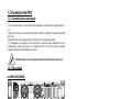
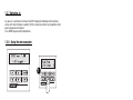
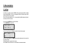
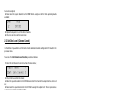
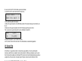
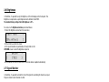
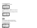
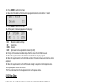
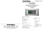
Powerlight 612 P r o f e s s i o n a l D i m m e r User’s Manual rel. 1.03 GB I D F E General instructions Read the instructions in this handbook carefully, as they give important information regarding safety during installation, use and maintenance. Be sure to keep this instruction manual with the unit, in order to consult it in the future. If the unit is sold or given to another operator, make certain that it always has its manual, to enable the new owner to read about its operation and relative instructions • • • • Do not dismantle or modify the unit. Make certain that no inflammable liquids, water or metal objects enter the unit. Should any liquid be spilled on the unit, disconnected the power supply to the unit immediately. In the event of serious operating problems, stop using the unit immediately and either contact the nearest SGM sales point for a check or contact the manufacturer directly. • Do not open the unit - there are no user serviceable parts inside • Never try to repair the unit yourself. Repairs by unqualified people could cause damage or faulty operation. Contact your nearest authorized service centre. Always insist on original spare parts being fitted. Powerlight 612 version1.03 Safeguard the environment: don't throw batteries, accumulators or packaging material into your waste bin - return them to your reseller or take them to the nearest special waste collection point. GB I D F E appendix 1 General warranty conditions • The unit is guaranteed for 12 months from the date of purchase against material and manufacturing defects. • Breakdown caused by carelessness and improper use of the unit is excluded. • The guarantee is no longer valid if the unit has been tampered with or repaired by unauthorized personnel. • The replacement of the unit is not foreseen by the guarantee. • External parts, knobs, switches, removable parts and lamps are excluded from the guarantee: these are covered by their manufacturers' guarantee conditions. • Transport costs and related risks are borne by the unit's owner. • The guarantee is valid to all effects only on presentation of the guarantee certificate to the manufacturer or the nearest SGM technical assistance centre. Always quote the unit's serial number and model when contacting your reseller for information or assistance. How to contact SGM Elettronica Our customer assistance service can be contacted as follows: The offices are open from Monday to Friday, from 8.30am to 12.30pm and from 2.30pm to 6.30pm. (Italian local time: GMT + 1 - Daylight-saving time from March to October (+1 hour)) Powerlight 612 version1.03 Fax (24/24 ore): +39-0721-476170 Tel: +39-0721-476477 http: www.sgm.it E-Mail: [email protected] 2 Index General Instructions General guarantee conditions How to contact SGM Elettronica Index Introduction 1 - Main features 1.1 - Technical specifications 1.2 - Installation 1.2.1 - Packaging 1.2.2 - Contents 1.2.3 - Before installation 1.3 - P612 connections 1.3.1 - Connecting to the mains supply 1.3.2 - Rear panels 1.3.3 - DMX signal cable 1.3.4 - DMX line connection example 1.3.5 - DMX termination construction 1.3.6 - RS-232 connection 1.3.7 - Switching on 1.3.8 - Using the microcomputer 2 - Description of the menu 2.1 - Soft Patch 2.2 - Set chn mode 2.3 - Set chn level 2.4 - Set pre heat 2.5 - Channel test 2.6 - Brightness 2.7 - Signal Monitor 2.8 - Vphase Monitor 2.9 - Version 2.10 - Run Autotest 2.11 - Set voltage 2.12 - Edit chase 2.13 - Run chase 2.14 - EQ curves 3 - Protections 3.1 - Overheating protection 3.2 - Overload protection 3.3 - Short-circuit protection 3.4 - Protection against incorrect connections 4 - Error messages GB I D F Powerlight 612 version1.03 1 2 2 3 4 5 5 6 6 6 6 7 7 7 8 8 9 9 10 10 11 11 11 12 12 13 14 14 14 15 15 16 16 17 18 19 19 19 19 19 19 E appendix 3 Introduction Powerlight 612 version1.03 Power Light P612 is a new digital dimmer entirely designed and developed by SGM's Research & Development Department. Careful study of its functions, selection of innovative material and ongoing technical updates have resulted in the manufacture of a truly unique product, able to satisfy the requirements of applications in the live sector and well as fixed installations. Particular care has been taken with the design of the cooling system, which also enabled the unit's dimensions to be kept down to 2 rack units. This enables the dimmers to be tacked without leaving space for air circulation between them, thus considerably reducing the space taken up in the event of installation in racks. Use of the unit's fans does not in any way jeopardise the possibility of using the dimmer in locations in which noise has to be kept to a minimum, as Power Light P612 uses very low-noise fans which are silent even when operating; their rotation speed is also electronically controlled and directly proportional to the dimmer's internal temperature. The fact that it's able to be used without necessarily being controlled by a lighting control desk makes Power Light P612 extremely versatile and enables it to be used in any sector. Powerful software keeps the various sections of the dimmer under constant control, intervening with special protection procedure in the event of faulty operation, and indicating any irregularities. The Power Light P612 has been built in compliance with current CE norms.page 6 P612D Designed and Manufactured in Italy by SGM Elettronica srl Printed in June, 2001 • Rel. 1.03 4 1. Main features • Power supply: three phase 380V 3 PHASES + NEUTRAL, or single phase 110 - 220 V. Mains frequency 50/60 Hz. The power supply for the electronics' logic part is taken from the T phase + NEUTRAL. • Maximum absorption: 72 Amps with three phase connection; 25 Amps with single phase connection • Input signal: DMX 512 or RS232 • Cooling: forced ventilation by means of two rear-mounted fans. Rotation speed is directly proportional to the temperature on the cooling fins. • Protections: are far as the output channels are concerned, thermal and electronic protections are provided against overloading and short-circuiting. The input power supply circuit on the other hand has twin protection (electronic and via fuses). • Microcomputer: located on the front of the P612, this comprises a display with six buttons below it, enabling to carry out all settings necessary for correct installation, as well as testing all the functions. • Operating modes: can be controlled using a lighting control console or used a stand-alone unit. In fact, it's possible to set the output level of the individual channels, or create 8 Chases with up to 32 steps (scenes) in each Chase. power supply The logic power supply Mains frequency Output current rated output: output voltage: fuse1: fuse2: Type of load: Interference filter Inputs: Output connectors: Frame dimensions Weight single phase 110/220 V 3-phase 3/N/PE 380V is taken from the load power supply 50/60 Hz 12Amps per channel 16Kw 110/230 V. 50/60 Hz 250V -25A TH internal 250V -1A TH internal resistive or inductive 50 mA/µsec DMX or RS232 SOCAPEX - CABUR - ILME 16 (HARTING) two 19" rack units (L x H x D): 442 x 84 x 330 mm 6kg. SGM Elettronica reserves the right to improve or modify their products at any time without prior notice. Always consult the handbook of the unit being used to avoid errors and differences between the actual functions and those shown in the manual. GB I D F E appendix 5 Powerlight 612 version1.03 1.1 Technical specifications 1.2 Installation 1.2.1 Packaging KEEP THE PACKAGING MATERIAL. Packaging material (plastic bags, polystyrene foam, nails, etc.) must not be left within children's reach, as it can be dangerous. Use the original packaging if the unit has to be returned to the manufacturer for repair or maintenance, as it has been specifically design to protect the unit during transport. 1.2.2 Contents After opening the box, check that the packaging contains the items in the following list, and make certain that the unit is in perfect condition. If in doubt, do not use the unit and contact an authorized SGM Technical Assistance Centre and the transport company. In fact, only the consignee can claim for any damage sustained by the unit during transport • Power Light P612 • Guarantee • Instruction manual • 1 XLR 5 P male connector • 1 XLR 5 P female connector 1.2.3 Before installation Powerlight 612 version1.03 Read the following warnings before beginning installation. • This unit is not intended for home use. • Disconnect the power supply before carrying out any work on the unit. • Electrical work necessary for installing the unit must be carried out by a qualified electrician or experienced person. • Before connecting the unit, make certain that the data on the plate correspond to the mains power supply • Avoid installing the units near sources of heat. • Install the unit in a well-ventilated location. Avoid blocking the air intake and output vents. • Never use the unit under the following conditions: - In places subject to excessive humidity - In places subject to vibrations or bumps. - In places with a temperature of over 45°C or less than 2°C • Protect the unit from excessive dryness or humidity (ideal conditions are between 35% and 80%). Attention! The unit must be grounded. If this rule is not followed, the guarantee will automatically be considered null. page 8 P612D 6 1.3 Connection the P612 1.3.1 Connecting the power supply • It must be connected to a circuit with a thermal-magnetic cut-off switch.(see appendix page 1, 2, 3) • Make certain that the cross-section of the socket's cables is sufficient for the power absorbed by the unit. • Should it be necessary, replace the fuses with others of the same type and value. • It's inadvisable to use adapters, in-line connectors or extension cables. Should their use be indispensable, make certain they're in compliance with current safety norms regarding component quality and cable length/cross-section. Attention! Class 1 unit. The ground conductor must be part of the power cord 1.3.2 Rear panels cod 004-1032 CABUR 11 dmx 22 33 44 5 6 N R S T earth N input Disconnect from main source before opening. Do not obstruct air vents. Disconnect from main source Non aprire prima di avere before lapparecchio. opening. scollegato Do Non not ostruire obstruct air vents. le ventole. Vor dem öffnen, output stromprima Ausschalten. Nonden aprire di avere Du müßt die Flügelrad scollegato lapparecchio. nicht verstpften. Non ostruire le ventole. see top cover for pin out Antes de abrir la tapa, desconectar la maquina. Non obstruir los rotores. Avant d'ouvrir, s'assurer que l'appareil il n'est pas sous tension. Ne pas obstruir les rotors. load loadphase outputs out Please see on the top cover for serial number, part number and customer informations. main maininput in inductive or resistive logic main is R T phase + N see top cover for pin out & informations R, S, T phases - Neutral - Earth max load 12A/ch AC / 50-60Hz inductive or380V restive toppin cover see top coverseefor outfor details cod 004-1034 SOCAPEX dmx load out main in R, S, T phases - Neutral - Earth 110 to 380V AC 50Hz, 60Hz input Disconnect from main source before opening. Do not obstruct air vents. Non aprire prima di avere scollegato lapparecchio. Non ostruire le ventole. output Vor dem öffnen, den strom Ausschalten. Du müßt die Flügelrad nicht verstpften. Please see on the top cover for serial number, part number and customer informations. max load 12A/ch inductive or restive see top cover unit for pin out Powerlight 612 version1.03 see top cover for pin out Antes de abrir la tapa, desconectar la maquina. Non obstruir los rotores. Avant d'ouvrir, s'assurer que l'appareil il n'est pas sous tension. Ne pas obstruir les rotors. cod 004-1036 ILME16 dmx Output channels 2 3 4 5 6 main in input 1 Disconnect from main source before opening. Do not obstruct air vents. output Non aprire prima di avere scollegato lapparecchio. Non ostruire le ventole. see top cover for pin out GB R, S, T phases - Neutral - Earth 110 to 380V AC 50Hz, 60Hz max load 12A/ch inductive or restive see top cover unit for pin out Please see on the top cover for serial number, part number and customer informations. I D F E appendix 7 1.3.3 DMX signal cable construction Power Light P612 has a DMX 512 input that uses standard XLR 5-pin connectors. When connecting, screened cable in compliance with EIA RS-485 specifications and with the following characteristics must be used: - 2 conductors plus screen - 120 Ohm impedance - low capacity - maximum transmission rate 250Kbaud. Connecting the cable: see diagram, taking care to ensure that the screen is connected to Pin 1 1 5 4 3 COMMON DMXDMX+ 2 Attention: the cable screen (braid) must NEVER be connected to the system's ground, as this would cause faulty unit or controller operation. 1.3.4 Example of DMX line connection 11 dmx input DMX line 22 33 44 5 6 N R S T earth N Disconnect from main source before opening. Do not obstruct air vents. Disconnect from main source Non aprire prima di avere before lapparecchio. opening. scollegato Do Non not ostruire obstruct air vents. le ventole. output Vor dem öffnen, DIMMR 0 COLOR 0 GOBOS 0 SHUTT 0 ROTGB 0 FROST 0 - 0 - 0 Antes de abrir la tapa, desconectar la maquina. Non obstruir los rotores. Avant d'ouvrir, s'assurer que l'appareil il n'est pas sous tension. Ne pas obstruir les rotors. see top cover for pin out Pilot2000 stromprima Ausschalten. Nonden aprire di avere Du müßt die Flügelrad scollegato lapparecchio. nicht verstpften. Non ostruire le ventole. main maininput in load loadphase outputs out inductive or resistive Please see on the top cover for serial number, part number and customer informations. logic main is RT phase + N see top cover for pin out & informations universal dmx controller on/off operations setup utility copy enter play extra lamp reset edit levels times preset unit step 11 dmx 100% input 90 80 smpte rec 70 60 programming keyboard 50 page 40 store 30 output 21 - 40 20 10 0 memory program chase psycho 33 44 5 6 N R S T earth N pan tilt Max 32 stromprima Ausschalten. Nonden aprire di avere Du müßt die Flügelrad scollegato lapparecchio. nicht verstpften. Non ostruire le ventole. Antes de abrir la tapa, desconectar la maquina. Non obstruir los rotores. Avant d'ouvrir, s'assurer que l'appareil il n'est pas sous tension. Ne pas obstruir les rotors. memory obj grand master 22 Disconnect from main source before opening. Do not obstruct air vents. Disconnect from main source Non aprire prima di avere before lapparecchio. opening. scollegato Do Non not ostruire obstruct air vents. le ventole. Vor dem öffnen, 1 - 20 see top cover for pin out main maininput in load loadphase outputs out inductive or resistive Please see on the top cover for serial number, part number and customer informations. logic main is RT phase + N see top cover for pin out & informations multifunction keyboard 2 or 22 3 or 23 4 or 24 5 or 25 6 or 26 7 or 27 8 or 28 9 or 29 10 or 30 11 or 31 12 or 32 13 or 33 14 or 34 15 or 35 16 or 36 17 or 37 18 or 38 19 or 39 20 or 40 DMX controller 11 dmx input 1 or 21 22 33 44 5 6 N R S T earth N Disconnect from main source before opening. Do not obstruct air vents. Disconnect from main source Non aprire prima di avere before lapparecchio. opening. scollegato Do Non not ostruire obstruct air vents. le ventole. Powerlight 612 version1.03 output Vor dem öffnen, stromprima Ausschalten. Nonden aprire di avere Du müßt die Flügelrad scollegato lapparecchio. nicht verstpften. see top cover for pin out Non ostruire le ventole. Antes de abrir la tapa, desconectar la maquina. Non obstruir los rotores. Avant d'ouvrir, s'assurer que l'appareil il n'est pas sous tension. Ne pas obstruir les rotors. Please see on the top cover for serial number, part number and customer informations. load loadphase outputs out inductive or resistive main maininput in logic main is RT phase + N see top cover for pin out & informations DMX Termination (Last unit) To avoid the risk of faulty operation, follow the following indications: Maximum cable length: Maximum N° of units connected: Cable run: Termination: 8 500m 32 Avoid running the cable alongside power lines. 120 ohm resistor across Pins 2 and 3 of the last unit. 1.3.5 DMX termination construction The termination avoids the possibility of the DMX 512 signal being sent back along the cable once it reaches the end: under certain conditions and with certain lengths, this could cause it to over-ride the original signal and cancel it. The termination is made by soldering a 120 1/4 W resistor across pins 2 and 3 of the 5-pole male XLR connector (see diagram). 1 5 4 3 2 120Ω 1.3.6 Connection RS-232 Powerlight 612 version1.03 Good quality screened RG 58 50 co-ax cables must be used for connections to avoid faulty equipment operation. Connectors used are always of the 5-pole XLR type. Refer to the diagram for wiring. GB I D F E appendix 9 1.3.7 Switching on As soon as it's switched on, the Power Light P612 display the SGM logo with the software version, after which it begins an autotest (self test) routine to check for any irregularities in the power supply and on the output. Press ENTER to proceed to the Main Menu. 1.3.8 - Using the microcomputer Powerlight 612 version1.03 1 1 - The menus are scrolled using the UP/DOWN buttons 2 - Press ENTER to confirm the menu choice. 3 - The same set of square brackets can be moved between the various fields using the RIGHT/LEFT buttons and their contents changed using UP/DOWN. To return to the Main Menu, press ESC. 10 2 - Menu descriptions 2.1 Soft Patch In this Menu, it's possible to assign the POWER LIGHT's physical channels (CHN) to the digital channels available (ADDR). This creates a correspondence between the Dimmer output channel and the channel that has to be controlled. There are 512 channels available for use, i.e., those provided for by DMX standard, and they don't necessarily have to be in succession. For access to the Soft Patch function, proceed as follows: 1. Select SOFTPATCH in the main menu; <Main Menu > [Soft Patch ] 2. Press Enter to confirm the choice; 3. Move the square brackets to the CHN field and select the channel to be assigned; CHN ADDR [1] 1 4. Move the square brackets to the ADDR field to assign the digital channel to the channel that has just been selected; 5. Repeat from point 3 to assign the other channels. 6. Press Esc to return to the main menu - the selected data are automatically updated. 2.2 Set Chn Mode (Channel Mode) - FIX. The output of channels set in this mode isn't controlled by a lighting control desk and remains fixed on a value which can be set later. - OFF. The output of channels set in this operating mode stays off and cannot be controlled by a lighting control desk - EXT. (EXTERNAL) Output channels set in this mode can only be controlled by a lighting control desk. The standard factory setting is with all the channels in EXT. For access to the Set Channel Mode function, proceed as follows: 1. Select the Channel Mode menu from the main menu; <Main Menu > [Set chn mode ] 2. Press Enter to confirm the choice; 3. Move the square brackets to the CHN field and select the channel to which the operating mode GB I D F E appendix 11 Powerlight 612 version1.03 In this Menu, it's possible to choose the operating mode for each individual channel. It is in fact possible to control the Power Light's channels independently or via a lighting control desk. There are three operating modes available: has to be assigned; 4. Now move the square brackets to the MOD field to assign one of the three operating modes available; CHN MOD 2 [FIX] 5. Repeat from point 3 to set the other channels. 6. Press Esc to return to the main menu: 2.3 Set Chn Level (Channel Level) In this Menu it's possible to set the level of each individual channel configured in FIX mode in the previous menu. To access the Set Channel Level function, proceed as follows: 1. Select the Set Channel Level menu from the main menu; <Main Menu > [Set chn level ] 2. Press Enter to confirm the choice; 3. Move the square brackets to the CHN field and select the channel the output level has to be set on; 4. Now move the square brackets to the LEV field to assign the output level. This is expressed as a decimal value of between 000 and 255; CHN LEV 2 [255] 5. Repeat from point 3 to set the other channels. 6. Press Esc to return to the main menu: the selected data are automatically updated. Powerlight 612 version1.03 2.4 Set Pre Heat In this Menu, it's possible to set the pre heat (warm-up) level of each individual channel. Incandescent lamps' behaviour varies according to the power voltage they are supplied. When they are cold, before voltage is applied, the filament has a very low resistance, so at the moment in which the voltage is applied, a very high current will pass through the lamp. This explains why frequent voltage changes can have a negative effect on lamp life: it's therefore indispensable to set warm-up level. This enables to set the minimum current which must pass through in the lamp when it is not lit, in order for the absorption of current to be reduced and lamp life increased. This is expressed as a percentage of between 0% and 9.9% and is usually left at zero for inductive loads (neon, par 36), whereas for resistive loads it varies according to the type of lamp used. For a good warm-up, it's sufficient to increase the level until the filament becomes just visible. Standard factory warm-up setting is 4% 12 For access to the Set Pre Heat function, proceed as follows: 1. Select the Set Pre Heat menu from the main menu; <Main Menu > [Set pre heat ] 2. Press Enter to confirm the choice; 3. Move the square brackets to the CHN field and select the channel whose pre-heat level has to be set; 4. Now move the square brackets to the LEV% field to assign the pre-heat level. This is expressed as a percentage with a value of between 0 and 9.9%; CHN LEV% 6 [4.0%] 5. Repeat from point 3 to set the other channels. 6. Press Esc to return to the main menu: the selected data are automatically updated. 2.5 Channel Test In this Menu, it's possible to check if a channel has any problems. In fact, by selecting the channel on which there are doubts, Power Light controls its efficiency, allowing to vary its value from 0 to maximum output and switching off the channels not involved and ignoring any previous assignments or the presence of an input signal. Only one channel can be checked at a time. For access to the Channel Test function, proceed as follows: 1. Select the Channel Test menu from the main menu <Main Menu > [Channel test ] CHN LEV 1 [0] Powerlight 612 version1.03 2. Press Enter to confirm the choice 3. Move the square brackets to the CHN field and select the channel to be checked 4. Now move the square brackets to the LEV field to assign the output level 5. Repeat from point 3 to set the other channels 6. Press Esc to return to the main menu: the selected data are updated automatically. GB I D F E appendix 13 2.6 Brightness In this Menu, it's possible to vary the brightness of the LCD display on the front panel. This brightness is expressed as a percentage and varies between 0 and 100%. The standard factory setting of the LCD brightness is 75% For access to the Brightness function, proceed as follows: 1. Select the Brightness menu from the main menu; <Main Menu > [Brightness ] 2. Press Enter to confirm the choice; 3. The square brackets are positioned on the only field. Use the UP/DOWN arrows to reach the brightness required. < BRIGHT > [ [75%] ] 4. Press Esc to return to the main menu: the selected data are updated automatically. 2.7 Signal Monitor In this Menu, it's possible to check the level of the signal for controlling the channels on input. Only one channel can be checked at a time. For access to the Signal Monitor function, proceed as follows: 1. Select the Signal Monitor menu from the main menu; <Main Menu > [Signal monitor] Powerlight 612 version1.03 2. Press ENTER to confirm the choice; 3. The square brackets will be positioned on the CHN field to allow the channel to be selected. CHN LEV [1] 0 4. Once the channel has been selected, the signal level will automatically appear in the LEV field. This field cannot be modified as it only displays the signal level on input. 5. Press ESC to return to the main menu. 2.8 Vphase Monitor In this Menu, it's possible to check that there is voltage on the three input phases (R-S-T). Power Light in fact measures the effective VRMS voltage between each phase and neutral. Vphase Monitor is a menu only used for consultation, in which no parameters can be changed. 14 For access to this function, proceed as follows: 1. Select the VPHASE MONITOR menu from the main menu; <Main Menu > [Vphase monitor] 2. Press ENTER to confirm the choice; 3. The square brackets will be positioned on the PHASE field to allow the required phase to be selected 4. Once the phase has been selected, the voltage value automatically appear in the VOLT field PHASE VOLT [T] 224 5. Press ESC to return to the main menu. 2.9 Version This Menu gives information on the software version installed in the Power Light. Version is a menu only used for consultation, in which no parameters can be changed. For access to this function, proceed as follows: 1. Select the Version menu from the main menu; <Main Menu > [Version ] 2. Press ENTER to confirm the choice; 3. At this point, the current version of the software will appear on the display. SGM Electronics P612 ver. 1.00 4. Press ESC to return to the main menu. This Menu runs an autotest routine which enables irregularities to be found in some crucial points of the Power Light. In fact. the following parameters are checked: - correct operation of both fans; - the voltage on the three input phases; - any excess voltage on input, - any overloading on the power output; - any short-circuitng on the power output; - the presence (or not) of DMX signal on input; - the presence (or not) of RS-232 signal on input; - the temperature on the cooling fins expressed in degrees Centigrade and Fahrenheit. Run Autotest is only an executive menu - no parameters can be modified. For access to this function, proceed as follows : GB I D F E appendix 15 Powerlight 612 version1.03 2.10 Run Autotest 1. Select the Autotest Run menu from the main menu; <Main Menu > [Version ] 2. Press Enter to confirm the choice; 3. A this point, the results of the measurements made for all the abovementioned parameters will appear one after another on the display. AUTOTESTING [OVERLOAD NO] 4. Press Esc to return to the main menu. 2.11 Set Voltage In this menu, it's possible to set the maximum voltage level for controlling the load for each single output channel. This voltage can be set between 60V and 240V. Factory-set default voltage is 220V. For access to the Set Voltage function, proceed as follows: 1. Select the Set Voltage menu from the main menu; <Main Menu > [Set voltage ] 2. Press ENTER to confirm the choice; 3. Move the square brackets to the CHN field and select the channel whose output level has to be assigned; CHN LEV [1] 220 Powerlight 612 version1.03 4. Now move the square brackets to the LEV field to assign the output level, which is expressed as a decimal value between 60 and 240; 5. Repeat from point 3 to set the other channels. 6. Press ESC to return to the main menu: selected data are updated automatically. 2.12 Edit Chase The P612 has been designed and built so that it can also be used as a free-standing unit, without the aid of an external controller. It's possible to create 8 different sequences (Chases) with a maximum of 32 scenes (Steps) each. For access to the programming function of the Edit Chase menu, proceed as follows: 1. Select the EDIT CHASE menu from the main menu; 16 <Main Menu > [Edit chase ] 2. Press ENTER to confirm the choice; 3. Now select the number of the Chase to be programmed, which can be between 1 and 8 <Edit chase > Chase [1] 4. Press ENTER to confirm the choice; 5. At this point, the following appears on the display: LN ST CHN [10] 1 1 LEV 255 LN: Maximum number of steps ST: Current step CHN: Channel LEV: light output level assigned to the channel (0-255) 6. Firstly, set the maximum number of steps that the chase in the LN field must have 7. Move the square brackets to the ST field and select the first step to program. 8. Move the square brackets to the CHN field and select the channel whose output level has to be adjusted. 9. Move the square brackets to the LEV field and change the output level to the required value. 10. Repeat points 7-8-9 for all the steps. 11. Press ESC to confirm the changes and return to the previous menu. 2.13 Run Chase In this menu, it's possible to run the Chase previously programmed with the possibility of adjusting the chase's times and master level. To access the programming function of the Run Chase menu, proceed as follows: 1. Select the RUN CHASE menu from the main menu; <Main Menu > [Run chase ] CHS CR SP LEV [1] 55 55 255 CHS: CR: SP: LEV: Powerlight 612 version1.03 2. Press ENTER to confirm the choice; 3. At this point, the following appears on the display: Chase CROSS Time expressed in secondsi SPEED expressed in seconds general light output level assigned to the CHASE (0-255) 4. For the chase selected in the CHS field, set the CROSS and SPEED times required and the general light level. 5. Press ESC to confirm changes and return to the main menu. GB I D F E appendix 17 2.14 Curve Equaliz (Curve Equalization) In this menu, it's possible to assign each channel the most suitable setting for controlling the load on output according to the type of lamp used. The 6 curves available are shown in the diagram. For access to the Curve Equal function, proceed as follows: 1. Select the Curve Equal menu from the main menu; <Main Menu [Curve > Equaliz] Powerlight 612 version1.03 2. Press ENTER to confirm the choice; 3. Move the square brackets to the CHN field and select the channel whose equalization curve has to be changed CHN CURVE N¯ [1] 1 4. Move the square brackets to the CURVE N° field and select the equalization curve to be assigned to the chosen channel. 5. Press the ESC button to return to the main menu: the selected data are automatically updated 18 3 - Protections Particular protections are provided to avoid any faulty operation seriously damaging the Power Light. These protections are: 3.1 - OVER-HEATING PROTECTION: the maximum temperature allowed is 90ºC and is measured on the cooling fin on the power section. If this temperature is exceeded, the output is disabled until temperature returns within the foreseen limits. At 80°, an over-heating pre-alarm message is given. 3.2 - OVERLOAD PROTECTION: the output is electronically limited to a maximum of 12 Amps per channel no matter what load is applied 3.3 - PROTECTION AGAINST SHORT-CIRCUITING: should a short-circuit occur, the Power Light immediately switches off the channel in question and then attempts to switch it on slowly after approximately 8 sec.; if the short-circuit persists, Power Light switches the channel off again and then attempts to switch it on. 3.4 - PROTECTION AGAIN INCORRECT CONNECTIONS: regarding the power supply circuit. There are two protections: an electronic one which blocks the power supply and indicates the phase in question on the display, and a fuse which blows to avoid overloading damaging the unit's internal circuitry. 4 - Error messages Error messages are indicated by the display giving a long flash. Should a message indicating an irregularity appear, switch off the Power Light immediately, find the cause and eliminate it. CAUSE No Signal No DMX (RS232) signal on in input Signal error Incorect DMX (RS-232) signal Fan Fail 1 Fun 1 is not running Fan Fail 2 Fun 2 is not running Over Voltage(R) High voltage on R phase Over Voltage(S) High voltage on S phase Over Voltage(T) High voltage on T phase Over Load This message is followed by the number of the channel/channels which is/are overloaded. Short Circuit This message is followed by a list of the schort- circuited channels HighTemperature Over Powerlight 612 version1.03 Message displayed heating If there are several messages simultaneously, they appear one after another. GB I D F E appendix 19 M 001225 SGM Elettronica srl Via Pio La Torre, 1 • 61010 Tavullia (PS), Italy Tel. +39 0721 476477 • Fax +39 0721 476170 e-mail: [email protected] • http://www.sgm.it